Table of contents. in.k200 keypad overview - introduction function description instructions Typical settings...
|
|
|
- Terence Warren
- 5 years ago
- Views:
Transcription
1
2 table of contents Table of contents introduction... 3 warnings...4 features... 5 overview - overview dimensions in.k200 dimensions...9 installation - floor installation wall installation in.k200 installation and connections - installing the in.k connecting main keypad to...13 connections - electrical wiring North American model electrical wiring European model.ce heater connections in.link connectors Power-up & breaker setting Programming the in xe...22 in.k200 keypad overview - introduction function description instructions Typical settings...34 error codes Spa pack error codes summary - error codes Hr error condition Prr error condition HL error condition Flo error condition UPL error condition AOH error condition OH error condition

3 table of contents Troubleshooting - Pump 1 doesn't work Pump 2 or blower doesn't work Circulation pump doesn't work Ozonator doesn't work Nothing seems to work Spa not heating Keypad doesn't seem to work gfci trips...62 step by step field replacement procedure...63 how to replace the heater...70 specifications


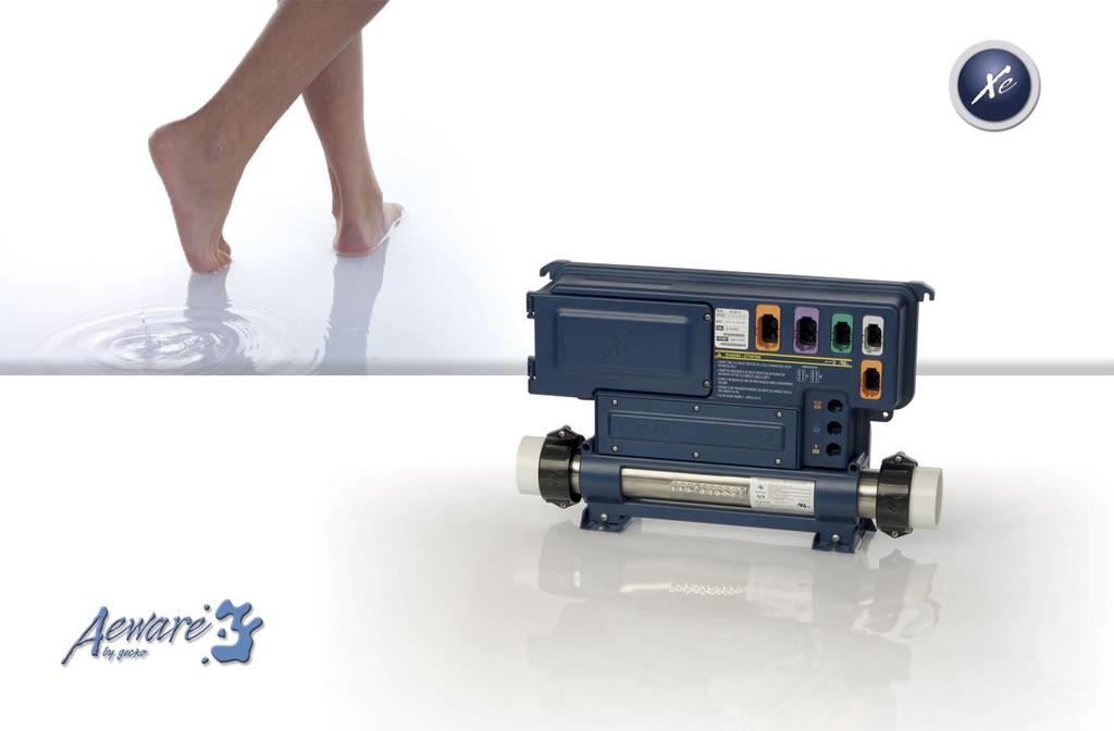
4 Introduction Entry-level spa system Congratulations! You have purchased one of the finest entry-level spa packs available. To install, use and enjoy your spa system take the time to carefully read these instructions. The has been designed for these typical spa configurations: Single Pump System Dual Pump System Pump & Blower System Dual Pump & Blower System In.xe can be wall-mounted or installed on its mounting base and comes with an integrated heat.wav water heater. 3
5 Warnings WARNINGS: Before installing or connecting the unit, please read the following. * FOR UNITS FOR USE IN OTHER THAN SINGLE-FAMILY DWELLINGS, A CLEARLY LABELED EMERGENCY SWITCH SHALL BE PROVIDED AS PART OF THE INSTALLATION. THE SWITCH SHALL BE READILY ACCESSIBLE TO THE OCCUPANTS AND SHALL BE INSTALLED AT LEAST 5 FEET (1.52 M) AWAY, ADJACENT TO, AND WITHIN SIGHT OF THE UNIT. * ANY DAMAGED CABLE MUST BE IMMEDIATELY REPLACED. * TURN POWER OFF BEFORE SERVICING OR MODIFYING ANY CABLE CONNECTIONS IN THIS UNIT. * TO PREVENT ELECTRIC SHOCK HAZARD AND/OR WATER DAMAGE TO THIS CONTROL, ALL UNUSED RECEPTACLES MUST HAVE A DUMMY PLUG. * LOW VOLTAGE OR IMPROPER WIRING MAY CAUSE DAMAGE TO THIS CONTROL SYSTEM. READ AND FOLLOW ALL WIRING INSTRUCTIONS WHEN CONNECTING TO POWER SUPPLY. * THIS PACK CONTAINS NO SERVICEABLE PARTS. CONTACT AN AUTHORIZED SERVICE CENTER FOR SERVICE. * ALL CONNECTIONS MUST BE MADE BY A QUALIFIED ELECTRICIAN IN ACCORDANCE WITH THE NATIONAL ELECTRICAL CODE AND ANY STATE, PROVINCE OR LOCAL ELECTRICAL CODE IN EFFECT AT THE TIME OF THE INSTALLATION. * THIS CONTROLLER MUST NOT BE INSTALLED IN PROXIMITY OF HIGHLY FLAMMABLE MATERIALS. 4
6 features In.xe boast a long list of technical features. Each of them stands on its own merits and contributes to bring to equipped spa owners the most advanced solutions available to them: In.put new input terminal bloc In.put was designed to ease wire insertion (up to # 4 AWG) and connections. Tighter input connection reduces heat generated for increased component lifetime. In.kin kinetic heat monitoring First ever UL approved kinetic heating protection manages water temp. increase generated by pump heat dissipation. Hardware protection shuts all accessories off if it senses water overheat. In.seal watertight protection In.seal provides extra level of protection against water infiltration. Connectors and power box are designed to be watertight and no water can be in direct contact with electrical components. In.flo dry-fire protect A new heater safety system located in the in.therm power box - an all-electronic dry-fire protection. In.axess board access prevention Electronic components are placed into separate and inaccessible compartments. Only serviceable parts are made accessible to service technicians. In.t.cip water temp. algorithm In.t.cip is an intelligent water temp. refresh algorithm that calculates optimal time to start pumps and get water temp. readings. In.t.cip continuously readjusts heater start time. 5
7 features In.link ingenious plugs and connectors In.link cables are very cool output and input plugs and connectors that come with colored and tagged polarizers. Totally waterproof, they are designed to be easily configured and to ensure that all cables of equipment used to make a spa or an hot tub work properly are well connected at their intended connection port, eliminating any risk of mis-wiring. In.stik automated software upload In.stik a pen drive with an in.link connector very similar to a USB memory stick. It connects to and contains data to program or configure its system. In.xe executes the data upload automatically. Specifications Refer to the detailed specification chart printed in Annex. 6
8 overview Door to access power input connectors and fuses Installation brackets Main power entry connection Accessory fuse Pump 2 fuse Pump 1 fuse Transformer fuse Pump 1 connector Pump 2 connector 2 connectors for outputs controlled by independent relays (for oz, cp, light, blower or any other accessories) (120/240 vac 5 Amp) Connector for direct 120/240 vac 5 Amp output (for in.play audio or video accessories) Main keypad connector Main power cable input entry Communication connector (in.stik, in.watch) Access to heater connections Mounting feet Bonding lug heat.wav heater Light 12 vac connector (1 amp max) Note: No connectors should remain unplugged. Use blank plugs to fill unused connectors. 7
 Side view 5.51\" (140 mm) 2.")
 4.5\" (114.3 mm) 19.32\" (490.7 mm) Ø.")
 Bottom view 6\" (152 mm) 3\" (76 mm) 8.")
 3.9\" (98.3 mm) Rear view 1.2\" (30.")
9 overview dimensions: Front view 17.38" (441.5 mm) Side view 5.51" (140 mm) 2.75" (69.9mm) 11.75" (298.5 mm) 5.69" (144.5mm) 4.5" (114.3 mm) 19.32" (490.7 mm) Ø.25" (6 mm) 5.37" (136.4 mm) Bottom view 6" (152 mm) 3" (76 mm) 8.3" (210 mm) 4.2" (106.7 mm) 10.8" (275.6 mm) 3.9" (98.3 mm) Rear view 1.2" (30.5mm) Ø.25" (6 mm) 4x 11.0" (279.4 mm) 8
 Features: LED display 4 Keys 8 Light")
 Mechanical Specs: Weight: Dimensions (W x H x D):")

10 in.k200 dimensions in.k200 dimensions: 2" (51 mm) Features: LED display 4 Keys 8 Light indicators in.link connector 4.750" (120 mm) Mechanical Specs: Weight: Dimensions (W x H x D): Approvals: 0.41 kg (0.9 lbs) Front Panel: 120 mm x 51 mm x 43 mm (4.75" x 2" x 1.7") Soft gasket UV resistance (ASMTD4329) UL, CSA, TUV and CE 1.7" (43 mm) Specifications and design are subject to change without notice. 9


 screws backed by (2) washers.")

11 installation Floor installation procedure 4" The following material is recommended: 4- # 10 screws of appropriate length with round, truss or pan head. Slide back side of the unit's feet into the guide plate. It should easily slide into place. Now firmly attach unit to wooden base by using the remaining (2) screws backed by (2) washers to fix the front of the foot. Note: The spa pack must be installed at least 4 inches above potential flood level. If floor is on ground level, pack should be raised at least 4 inches. 4- washers 1/2 OD x 1/16" thickness. Select the most appropriate location on the floor for spa pack and firmly attach guide plate to wooden base with (2) screws backed by (2) washers. Warning: Beware the application of some products commonly used against corrosion (such as WD-40 family products) could damage the power box, due to a negative chemical reaction between some industrial oils and its plastic enclosure. Any other materials which may come in contact with the enclosure must be carefully evaluated under end use conditions for compatibility. Important! Please note that countersunk screws should not be used as they can damage the power box support. 10


 screws backed by")
 remaining screws and Note: Make sure")
12 installation Wall installation procedure The following material is recommended: 4- # 10 screws of appropriate length with round, truss or pan head. 4- washers 1/2 OD x 1/16" thickness. Use two (2) standard 2 x4 or 2x6 wall studs, spaced on 16-inch centers to affix the spa pack. In the case of a flat wooden surface: select the most appropriate location on wall for the spa pack. A square cutout of about 4-inch per side will be needed to allow the transformer to fit through it. Firmly attach, one at the time, upper mounting holes on each side of the spa pack with (2) screws backed by (2) washers. Firmly attach lower mounting holes on each side of the pack with the (2) remaining screws and (2) washers. Note: Make sure these (2) screws and (2) washers are installed. They will make the pack stable when input, outputs and accessory connectors will be inserted in their ports. 11
13 Keypad installation & connections Installing the in.k200 The keypad should be installed directly onto the spa (or very close to it) so that it is easily accessible to the user. 2 5/8" 66 mm To install the in.k200, drill two 1 (25 mm) diameter holes at 2 5/8 (67 mm) from center to center as illustrated. Cut out the material between the two holes (see illustration). Clean the installation surface and peel the adhesive gasket from the back of the keypad. Insert keypad and align it correctly, then ensure it's properly glued by gently pressing evenly on the entire surface. 1" 25,4 mm 1" 25,4 mm 1" dia. drill Gasket with adhesive 1" 1" 2 5/8" 12
. Note: always shut power down before connecting an accessory to the. Connect the main keypad in.")
14 Connecting main keypad to Keypad installation & connections in.k200 The in.k200 comes with a 10 ft cable and an in.link connector. To connect the in.k200, simply insert its in.link connector into the appropriate keypad connector (as illustrated). Note: always shut power down before connecting an accessory to the. Connect the main keypad in.k200 as indicated here. 13

15 Electrical wiring Electrical wiring North American model Main electrical box GFCI panel Warning! "For units for use in other than single-family dwellings, a clearly labeled emergency switch shall be provided as part of the installation. The switch shall be readily accessible to the occupants and shall be installed at least 5 feet (1.52 m) away, adjacent to, and within sight of the unit" This product must always be connected to a circuit protected by a ground fault interrupter. Proper wiring of the electrical service box, GFCI and terminal block is essential! Check your electrical code for local regulations. Only copper wire should be used, never aluminum Disposal of the product The appliance (or the product) must be disposed of separately in accordance with the local waste disposal legislation in force. 14

16 Electrical wiring Electrical wiring North American model bonding lug To install the wiring for the spa control, you'll need a Phillips screwdriver and a flat screwdriver. Loosen the 2 screws of the Spa Pack door and open it. Remove 5 1/2" of cable insulation. Strip away 1" of each wire insulation. Pull the cable through the cutout of the box and secure it with a strain relief (1" NPT strain relief; hole diameter: 1.335"). Make sure that only the uncut sheathing is clamped at this opening. Push the color-coded wires into the terminals as indicated on the sticker and use the flat screwdriver to tighten the screws on the terminals. After making sure wire connections are secure, push them back into the box and close the door. Tighten the 2 screws of the Spa Pack door. Connect the bonding conductor to the bonding lug on the front of the Spa Pack (a grounded electrode conductor shall be used to connect the equipment grounding conductors). 15
 Correct wiring of the electrical service box, GFCI, and pack terminal block is essential. Call an electrician if necessary.")

17 Electrical wiring Electrical wiring North American model Electrical wiring European model.ce Single-phase Dual-phase For 240 VAC (4 wires) Correct wiring of the electrical service box, GFCI, and pack terminal block is essential. Call an electrician if necessary. For 120 VAC (*3 wires) *If connected to a 3 wire system, no 240 VAC component will work. Refer to "Connections for 120v heater" section of this manual. In.xe.ce 230 VAC or 230/400 VAC Correct wiring of the electrical service box, RCD, and pack terminal block is essential! Call an electrician if necessary. Warning! In.xe.ce models must always be connected to a circuit protected by a Residual- Current Device (RCD) having a rated operating residualcurrent not exceeding 30 ma. 16

, but it can be converted to a dedicated 120v / 1kW by a simple switching a cable connection port. (Option available on NorthAmerican models only).")
18 Heater connections L2 L1 Ground N L1 Ground Heat.wav heater Connections for 230/240 VAC heater (4KW or 2 KW) Connections for 120v heater (1KW) In.xe comes with a high performance heat.wav heater. With no pressure switch, it features in.flo integrated dryfire protection. A watertight panel protects the heater and probe connectors. Removing the panel gives access to in.flo dry-fire protection and hi-limit/regulation probe connectors, line 1, line 2 and ground power input cables connection ports. The heat.wav heater is factory configured 240v /4 kw (or 2KW), but it can be converted to a dedicated 120v / 1kW by a simple switching a cable connection port. (Option available on NorthAmerican models only). Heat.wav specification summary: Supports 120v or 240v Protected by external breaker (not fused)* Incoloy or Titanium (optional) heater element for greater protection against corrosion. Note: European models are 230 or 240 VAC and are fuse protected 17


19 in.link connectors High Current Integrated latch Low Current Colored & tagged polarizers Low voltage In.link connectors In.xe features in.links connectors with colored and tagged polarizers. This new plug and connector technology has been specifically designed for easy and safe assembly. The tags are interchangeable depending on the output; the polarizers are designed to avoid misconnections. In.link connectors are easily and conveniently accessible from the front of the pack offering a wide range of possible connection configurations. In.link connectors come in 3 sizes (HC, LC and low voltage) for all types of inputs and output devices. 18 Latch snap & strain relief A latch mechanism is provided to maintain male and female connectors together. The tab provided on the male part gives the operator an audible and tactile feedback at the insertion of the cable in the female part. Once the latch is engaged, it will prevent both parts from separating unintentionally by vibration or shock. To unplug the male connector, a gentle press on the tab will allow the release of the locking mechanism to separate both parts. Watertight design UL & CE The female connector comes with a built-in seal ensuring a watertight connection assembly sealed from moisture and water ingress. This sealing is intended to be suitable for the NorthAmerican and European standards and the demanding spa environment.

20 in.link connectors Connector Map Female connector on Spa Pack Pump 1 connector Pump 2 connector Blower connector Ozonator connector Direct connector HC LC Keypad connector Comm connector Light connector In.link output connectors: High-Current - HC connectors: Output Typical Device Out 1 Pump 1 Out 2 Pump 2 Low-Current - LC connectors: (relay controlled) Output Typical Device Out 3 Blower Out 4 Ozonator Out 5 Audio/video (direct to line) Low-Voltage - LV connectors: Output Typical Device C Main keypad CO Comm. Connector (in.stik, in.watch) L1 Light 19
21 Power-up & breaker setting Valuable Tips Make sure that all valves are open in the spa plumbing and that you have a good water flow circulating from the primary pump into the heater. Important: a minimum flow rate of 18 gpm is required. Technical stuff There is no mechanical switch in the heater. Instead systems have integrated in.flo technology. The in.flo is an all electronic dry-fire protection device built-in 's heater. At power up, in.flo performs a flow check through the following process: Pump 1 starts for 2 min. The display will show " " during the check flow process. After 2 min. the system validates proper water flow. In case of failure, the systems tries again. The water temperature is shown on the keypad display. Once the water has reached the set point value plus 0.8 degrees F the heater is turned off. 20
.")
22 Power-up & breaker setting Make sure all accessories are linked to the bonding connector and connected to pack. Turn on the breaker. It's important to specify the current rating of the GFCI used to insure safe and efficient current management (and no GFCI trippings). Press and hold Light button until you access the breaker setting menu. The values displayed by the system correspond to 0.8 of the maximum amperage capacity of the GFCI. GFCI Br 60 Amp 48 Amp 50 Amp 40 Amp 40 Amp 32 Amp 30 Amp 24 Amp 20 Amp 16 Amp Use Up or Down button to select the desired value. Then press Light button to set breaker rating. Note: Every OEM has its own preset configurations. 21
.")
23 programming the in xe Programming the using the in.stik This feature is very useful on production lines to configure packs and in the field for service purposes like software updates. Follow these simple steps to upload new pre-determined low level program configurations into the spa pack. Insert the in.stik in the communication connector (see fig. above). Shut electrical power off. Turn power on. At power-up the system will upload all the different configurations set into the in.stik memory. The will then enter the low-level configuration menu. The keypad display will show L xx where "xx" represents the previous configuration number registered in the system. Use the Up/Down key to choose the new desired low level configuration number. Press the Prog. key to confirm the selected configuration (consult the configuration. If the Prog. key is not pressed within 25 seconds, the unit will exit this menu without changing any settings. Note: If the keypad in use does not have the Prog. key, use Light key instead. If at power-up of the system your keypad display shows the following message: "L ", it means that all low level configurations have been downloaded, but no configuration number has been chosen. 22
24 Programing the in xe Programming the using the keypad Although every spa pack is factory set, in certain cases when servicing or replacing a new unit in the field, it may be necessary to set a new predetermined low level program configuration into the spa pack. Follow these simple steps to re-enter the low level programming menu using the keypad: Press and hold the Pump 1 key for 30 seconds. The keypad display will show L xx where "xx" represents the previous configuration number registered in the system. Use the Up/Down key to choose the new desired low level configuration number and press the Program key to confirm the selected configuration (consult the configuration selection chart section in this manual). If the Program key is not pressed within 25 seconds, the unit will exit this menu without changing any settings. If at power-up of the system your keypad display shows the following message: "L ", it means that all low level configurations have been downloaded, but no configuration number has been chosen. Note: If the keypad in use does not have the Program key, use the Light key instead. 23
25 Programing the in xe Low Level Configuration Selection Chart Config. # P1 P2 BL CP configuration Ozone configuration Filter Type Heater Pump 1 2sp 1sp X Always on --- Clean, P1L P1 2 2sp 1sp X Always on --- Purge CP 3 2sp 1sp X --- On during Filter cycle, with P1 Clean, P1L P1 4 2sp 1sp - Duration filtration On during Filter cycle, with CP Clean, CP P1 5 2sp 1sp - Always on Always on with CP Clean, P1L CP 6 2sp 1sp - Duration filtration On during Filter cycle, with CP Clean, CP CP 7 2sp 1sp On during Filter cycle, with P1 Clean, P1L P1 8 2sp - X --- On during Filter cycle, with P1 Clean, P1L P1 9 2sp On during Filter cycle, with P1 Clean, P1L P1 10 1sp 1sp X --- On during Filter cycle, with P1 Clean, P1L P1 11 1sp 1sp - Duration filtration On during Filter cycle, with CP Clean, CP P sp 1sp - Always on Always on with CP Purge CP Note: Every OEM has its own preset configurations. The Low level configuration may differ depending on the manufacturer.
26 Programing the in xe programing field options In the event where none of the pre-determined low level program configurations built in the system suit your spa equipment assembly, it's possible to custom configure the system by manually entering key parameter settings. To access this menu, press and hold Prog. (or Light key) for 30 seconds. Use Up or Down key to choose setting. Press Prog. key (or Light key) to go to the next parameter. Parameter Display Options Description Pump 1 Config Pump 2 Config Blower Config Circ. Pump Config Ozone Config Ozone Pump Ozone Type Heater Pump Single-speed = 1 Dual-speed = 2 Not installed = 0 Single-speed = 1 Dual-speed = 2 Not installed = 0 Installed = 1 Not installed = 0 Installed = 1 Always on = 2 Not installed = 0 During filter cycle = 1 Always on = 2 Circulation pump = 0 Pump #1 = 1 Standard = 0 Timed = 1 Circulation pump = 0 Pump #1 = 1 Pump #1 configuration Pump #2 configuration Blower configuration Circulation Pump configuration Ozone generator configuration Pump associated to Ozone generator Type of Ozone generator Pump associated to Heater 25
27 Programing the in xe Parameter Display Options Description Filter Config Purge only = 0 With Circ. Pump = 1 With Pump #1, Low speed = 2 Filter cycle configuration Temp. Units Time Format Pump #1 High current Pump #1 Low current Pump #2 High current Pump #2 Low current F = 0 C = 1 No time display = 0 AM/PM format = 1 24H format = 2 Temperature units used on display Clock display format 1 to 20 amperes (10) Pump #1 High speed current 1 to 15 amperes (4) Pump #1 Low speed current 1 to 15 amperes (10) Pump #1 Low speed current 1 to 15 amperes (4) Pump #2 Low speed current Blower current 1 to 10 amperes (5) Blower current Circ. Pump current 1 to 5 amperes (2) Circulation Pump current Direct current 0 to 5 amperes (1) Direct accessory output current Heater current 4 to 17 (17) Heater current Input current 15 to 48 (on UL/CSA packs) (48) 15 to 32 (on CE packs) (32) Available household supply current 26

28

. Note: The following instructions are generic and provide a quick overview of the main functions.")
29 Keypad overview in.k200 Compact series of entry-level keypads that gives complete control to wet fingers! In.k200 is a compact keypad designed to be used with Aeware's spa systems. This new series of entry-level keypads comes in a waterproof plastic enclosure and is available in single pump, dual pump; dual pump/blower or pump/blower configurations. Easy to install, in.k200 comes with an in.link connector. Note: The spa control is also compatible with the following keypads: in.k200, in.k400, in.k450 in.k600 (static). K-19, k-35 and k-8 (with in.link connector). Note: The following instructions are generic and provide a quick overview of the main functions. Please refer to your own QRC for specific functions. 28


30 Keypad overview function description Smart Winter Mode indicator Pump 1 indicator Pump 2 indicator Blower indicator Light indicator Filter indicator Heater indicator Set Point indicator Key 1 Key 2 Light key Up/Down key 29
. A third time turns pump off.")

31 Instructions Key 1 Key 2 2 Pump (or single pump/blower) Key 2 (2 Pump/Blower) Light key Press Key 1 key to turn Pump 1 on at low speed. Press a second time to turn pump to high speed (with a dual-speed pump). A third time turns pump off. A built-in timer automatically turns pump off after a predetermined period of time, unless it has been manually deactivated. The Pump 1 indicator lights up when Pump 1 is on. With dual-speed pump, indicator will flash when Pump 1 is on at low speed. Press Key 2 key to turn Pump 2 or Blower on. Press a second time to turn pump or blower off. A built-in timer automatically turns pump off after a predetermined period of time, unless it has been manually deactivated. The Pump 2 and/or Blower indicator lights up when the corresponding output is on. Note: with dual-speed pump, indicator will flash when Pump 2 is on at low speed. Press Key 2 to turn Pump 2 on at high speed. Pressing a second time turns blower on. A third press turns Pump 2 off but leaves blower on. A final press turns blower off. A built-in timer automatically turns pump/blower off after a predetermined period of time, unless it has been manually deactivated. The Pump 2 and/or Blower indicator lights up when the corresponding output is on. Press Light key to turn light on. Press Light key a second time to turn light off. A built-in timer automatically turns light off after a predetermined period of time, unless it has been manually deactivated. The Light indicator lights up when light is on. 30


32 Instructions Up/Down key Off Mode Programming the system Setting filter cycle duration Use Up or Down key to set desired water temperature. The temperature setting will be displayed for 5 seconds to confirm your new selection. The "Set Point" icon indicates that the display shows the desired temperature, NOT the current water temperature! This mode allows you to stop all outputs for 30 minutes to perform a quick spa maintenance. Press and hold Key 1 key for 5 sec. to activate the Off mode. Quick press Key 1 key to reactivate the system before the expiration of the 30 minute delay. While the Off mode is engaged, the display will toggle between OFF and the water temperature. Depending on system configuration the system performs either purge cycles or filter cycles. Programming filter cycles To program the filter cycles, you must enter these parameters: duration and frequency. During a filter cycle, pumps & blower run at high speed for one minute to purge the plumbing. Pump 1 or CP then runs at low speed for the remaining of the cycle. Press and hold Light key until the display shows dxx, with "xx" representing the duration in hours. (Default: 2 hours). Use Up or Down key to change setting. 0 = no filtration 24 = continuous filtration Note: it's not recommended to set this to "0". 31
. (Default: twice a day). Use Up or Down key to change setting.")
33 Instructions Filter cycle frequency Programming purge cycles Purge cycle frequency Setting the temperature display units Press Light key again. The display will show Fx, with "x" representing the number of filter cycles per day (up to 4). (Default: twice a day). Use Up or Down key to change setting. When the desired setting is displayed, press Light key to confirm. A filter cycle will start immediately. The Filter indicator lights up when a filter cycle is on. To program the purge cycles, you must select the frequency. During a purge cycle, all pumps and the blower run for one minute. Press and hold Light key until the display shows Fx, with "x" representing the number of purge cycles per day (up to 4). Use Up or Down key to change setting. When the desired setting is displayed, press Light key to confirm. A purge cycle will start immediately. The Filter indicator lights up when a purge cycle is on. Quick press Light key again. The display will show either F or C. Use Up or Down key to change units. Press Light key a last time to go back to normal mode. F = Fahrenheit C = Celsius 32


34 Instructions Water temperature regulation Smart Winter Mode Cooldown In a regulation cycle, the system first generates water flow through the heater housing and the plumbing, in order to ensure accurate water temperature readings as well as avoiding heater activation in dry conditions. The system verifies periodically that all parameters are within normal range. If the readings received from the system are not valid, blanks (- - -) will be displayed until normal readings have been successfully found. After verifying pump activation and taking a water temperature reading if required, the system automatically turns the heater on to reach and maintain water temperature at Set Point. The Heater indicator lights up when the heater is on. It flashes when there is a request for more heat but the heater has not yet started. Our Smart Winter Mode protects your system from the cold by turning pumps on several times a day to prevent water from freezing in pipes. The Smart Winter Mode indicator lights up when the Smart Winter Mode is on. After heating the spa water to the desired Set Point, the heater is turned off, but its associated pump (Pump 1 Low-speed or CP) remains on for a certain amount of time to ensure adequate cooling of the heating element, this prolongs its useful life. The heater icon flashes during this time. 33
 to 104 F (40 C) Factory Default Set Point:")


 in.")
35 Typical settings typical settings: Ajustable Regulating Set Point: 59 F (15 C) to 104 F (40 C) Factory Default Set Point: Typical 95 F (35 C) / Max 100 F (38 C) Filter Cycle Duration: 0 to 24 hrs / Factory set at 2hrs Filter Cycle Frequency: 1 to 4 times a day / Factory set at 2 Filter Cycle Start: 00:00 to 23:59 / Factory set at 12:00 Pump Runtime: 1 to 255 min. / Factory set at 20 min. Light Timeout: 1 to 255 min. / Factory set at 120 min. in.k200 (LED display, 4 keys, 8 light indicators) Keypads available for the : in.k400 (LCD display, 6 keys, 10 function icons) in.k19 in.k35 in.k600 in.k8 in.k450 (LCD display, 6 keys, 10 function icons) 34
36 Spa pack error codes summary error codes Error codes indicate a failure condition or a problem which needs to be corrected to ensure proper functioning of the system. Both the error code and the water temperature are alternatively displayed. All errors codes will be displayed on the keypad display. Hr An internal hardware error has been detected in. Prr The Prr error message indicates a problem with regulation probe. The system is constantly verifying if temperature probe reading is within normal limits. HL Water temperature at the heater has reached 119 F. Do not enter spa water! FLO The system did not detect any water flow while the main pump was running. 35
37 Spa pack error codes summary error codes UPL No low level configuration software has been downloaded into the system. AOH Temperature inside the spa skirt is too high, causing the internal temperature in the to increase above normal limits. OH Water temperature in the spa has reached 108 F. Do not enter spa water! Specifications subjet to change without prior notice. 36
38 Hr error condition / flow chart & step by step An internal hardware error has been detected Flow chart Step-by-Step Restart the Spa Pack and start & stop all outputs. Replace Spa Pack, if problem persist. Restart the Spa Pack and start & stop all pumps and blower. If error reappears, replace Spa Pack. 37
39 Prr error condition / flow chart & step by step Regulation probe issue Flow chart Step-by-Step Verify if regulation probe is properly connected. Replace heater if problem persist. Replace Spa Pack, if problem persist. Verify if regulation probe (located above the heater) is properly connected. Replace heater if problem persists. Replace Spa Pack, if problem persists. 38
40 HL error condition flow chart The system has shut down because the temperature at the heater has reached 119 F (48 C). Take water temperature with a digital thermometer. Is water temp. 119 F or higher? * To Reset System: Turn power Off and On again at the main breaker. yes no ** Warning! handle with care as heater may be really hot! Are you getting correct water temperature reading on the display? When HL error condition occurs, does heater barrel feel hot? ** yes no yes no Is weather very hot? Verify if temperature probe is properly connected. If so, replace heater. Reset system.* Verify if anything is obstructing water flow (closed traps or dirty filters). Reset system.* Verify if Hi-Limit probe is properly connected. Reset system.* yes no Remove spa cover (even during the night) Start blower, if spa is equipped with one. Lower Set Point below actual water temperature. Heater indicator on keypad display should disappear. If HL error condition persists, replace Spa Pack. If problem persists, replace heater. Wait until spa cools down (add cold water if needed). Reset system.* Do you get a 240 VAC reading between the two heater wires on the board? yes no If problem persists, replace Spa Pack. Replace Spa Pack. Pump is overheating water during filter cycle. Lower filter cycle duration. Reset system.* 39
41 HL error condition step-by-step HL Probe & Temp Probe HL Water temperature at the heater has reached 119 F 1 Measure the temperature with a DIGITAL thermometer and compare its reading with temp. on the display. Make sure the temp. reading is lower than 119 F. 2 If reading is below 119 F: a- Check if heater barrel feels hot. If it s hot, verify if anything is obstructing water flow (closed valves or dirty filter). b- Shut power off and power the spa up again to reset the system. c- If HL error condition persists, replace heater. d- If HL error condition persists, replace Spa Pack. 3 If reading is 119 F or higher: Verify if the Temp. & High Limit probes are properly connected. Shut power off and power the spa up again to reset the system. If problem persists, replace heater. If problem persists, replace Spa Pack. 40
. Shut power off and power the spa up again to reset the system.")
42 HL error condition step-by-step N L2 L1 Ground If weather is very hot: If hot weather is not a factor: To shorten filter cycle duration: 1 Remove spa cover (even during the night). Start blower if spa is equipped with one. Wait until spa cools down (add cold water if necessary). Shut power off and power the spa up again to reset the system. 2 Lower Set Point below current water temperature. The Heater indicator should disappear from keypad display. 3 With a voltmeter, read voltage between the two heater terminals. 4 If you do read 240 VAC, replace Spa Pack. 5 If you do not read 240 VAC, pump may be overheating water during filter cycle. Shorten filter cycle duration. 6 Press and hold Light key for 5 seconds. Display will show a value that represents the filter cycle duration in hours. 7 Use Down arrow key to lower the number of hours. 0 = no filtration 12 = continuous filtration When the desired setting is displayed, press Light key again. The filter cycle will start immediately. 41
43 Flo error condition flow chart The system did not detect any water flow while the primary pump was running. Follow Troubleshooting Flow Chart below to identify the problem: Make sure that the low-level programming has been properly set, with or without circulation pump (depending on your system configuration). There must be adequate water in spa for normal use (a minimum of 18 gpm must circulate through the heater) Is pump working when you try to start it from keypad? yes no Is anything limiting flow of water into pipes? Refer to Pump not Working section. yes no Remove anything obstructing filter. Clear any air locks and verify water valves. Verify if in.flo cable is properly connected If problem persist, replace heater If problem persist, replace Spa Pack 42

44 Flo & UPL error conditions step-by-step in.flo cable No low level configuration software in system! Step-by-Step FLO Primary pump is activated but the system doesn't detect any water flow Make sure water valves are open and that water level is high enough. Check and remove anything obstructing the filter. Make sure there are no air locks (or that no object obstructs the passage of water in the heater channel). Pumps may make strange noises. Follow air lock procedure to clear them. Make sure that the pump associated to the heater (primary pump) is running. Make sure in.flo cable (located above the heater) is properly connected. If problem persists replace heater. If the problem is not solved replace Spa Pack. New low level configuration software needs to be downloaded into the spa system, without it the system will not be operable. Contact our toll free line for technical support ( ). Note: this line is dedicated to assist authorized service technicians and dealers only. 43
45 AOH error condition chart & step-by-step Temperature inside the spa equipment compartment is too high Flow chart Ensure adequate water level in spa for normal use Remove spa skirt and let system cool down, until the error clears. Replace Spa Pack, if problem persist. Step-by-Step There must be adequate water in spa for normal use (a minimum of 18 gpm must circulate through the heater). Remove spa skirt and let system cool down, until the error clears. If problem persists replace Spa Pack. 44

46 OH error condition chart & step-by-step Water temp. in the spa has reached 108 F Flow chart Step-by-Step Measure water temperature with a DIGITAL thermometer Are you getting correct temperature reading on the keypad display? yes no Remove spa cover and let system cool down, until the error clears. Replace heater, if problem persist Add cold water and lower filter cycles. Replace Spa Pack, if problem persist Replace Spa Pack, if problem persist Measure water temperature with a DIGITAL thermometer and compare its reading with temp. on the display. If temp. reading is different, replace heater. Remove spa cover and let spa cool down. Add cold water and lower filter cycles. If problem persists replace Spa Pack. 45
47 "Pump 1 doesn't work" flow chart If Pump 1 is not working, follow this troubleshooting flow chart: Have any error messages (FLO, OH, HL etc.) appeared on keypad display? yes no Refer to specific section indicated by error message. Verify if low-level programming is set properly. Does Pump 1 indicator appear on keypad display when you press Pump 1 key? yes no Is Pump 1 working in either speed? yes no Replace Pump 1 fuse. Pump 1 still not working! yes no Measure voltage on the board for both speeds. Do you get a 240 VAC reading (or 120 VAC for a 120 VAC pump) for both speeds? Problem solved. yes no Replace Pump 1. Replace Spa Pack. Replace keypad. If still not working replace Spa Pack. 46
48 "Pump 1 doesn't work" step-by-step Pump 1 does not work! Check for an error condition on keypad display. If there is one, refer to the specific section indicated by the error condition. Verify low level programming configuration. Verify if Pump 1 indicator appears on keypad display when you press Key 1 button. If Pump 1 indicator does not appear, use a spare keypad to verify if keypad is defective. If it is, replace keypad. If not, replace Spa Pack. If Pump 1 indicator appears when Key 1 button is pressed, verify if pump works in either speed. 47

49 "Pump 1 doesn't work" step-by-step Pump 1 fuse Pin 3 Pin 6 Pin 1 Pin VAC at P1 connector: Pin 3 & Pin VAC at P1 connector: Pin 6 & Pin 1 If Pump 1 does not work in either speed, replace Pump 1 fuse. If replacing the fuse is not effective or if Pump 1 works in only one speed, take voltage reading on the corresponding in.link connector. Turn Pump 1 to high speed and take voltage reading between: Pin 5 Pin VAC at P1 connector: Pin 3 & Pin 5 Pump up to 15 Amp : 240 VAC: Pin 2 & Pin VAC: Pin 2 & Pin 5 Your reading should be: Pin 5 Pin 6 120VAC at P1 connector: Pin 6 & Pin 5 Turn Pump 1 to low speed and take voltage reading between: 240 VAC: Pin 6 & Pin VAC: Pin 6 & Pin 5 If voltage is as it should be, replace Pump 1. If not, replace Spa Pack. Pump up to 20 Amp : 240 VAC: Pin 3 & Pin VAC: Pin 3 & Pin VAC for a 240 VAC pump 120 VAC for a 120 VAC pump Your reading should be: 240 VAC for a 240 VAC pump 120 VAC for a 120 VAC pump 48
50 "Pump 2 or blower doesn't work" flow chart If Pump 2 or blower is not working, follow this troubleshooting flow chart: Have any error messages (OH, HR, etc.) appeared on keypad display? yes no Refer to specific section indicated by error message. Verify if low level programming is set properly. Does Pump 2 or "Blower" indicator appear on keypad display when you press Pump 2 or blower key? yes no Is Pump 2 or blower working? yes no Replace Blower fuse. Pump 2 still not working! yes no Measure voltage on the board. Do you get a 240 VAC reading (or 120 VAC for a 120 VAC pump)? Problem solved. yes no Replace Pump 2 or blower. Replace Spa Pack. Replace keypad. If still not working replace Spa Pack. 49

51 "Pump 2 or blower doesn't work" steb-by-step Pump 2 or blower is not working! Check for an error condition on keypad display. If there is one, refer to the specific section indicated by the error condition. Verify low level programming configuration. Verify if Pump 2 or "Blower" indicator appears on keypad display when you press Key 2 button. If Pump 2 or "Blower" indicator does not appear, use a spare keypad to verify if keypad is defective. If it is, replace keypad. If not, replace Spa Pack. If Pump 2 indicator appears when Key 2 button is pressed, verify if pump works in either speed (if dual speed pump). 50


52 "Pump 2 or blower doesn't work" steb-by-step Pump 2 fuse Pin 2 Pin 6 Pin VAC at P2 connector: Pin 2 & Pin 1 Pin VAC at P2 connector: Pin 6 & Pin 1 Accessory fuse Pin 2 Pin 6 If "Pump 2" or "Blower" does not work in even when indicator is on, replace Pump 2 fuse or the accessory fuse for the blower. Pin VAC at P2 connector: Pin 2 & Pin 5 Pin VAC at P2 connector: Pin 6 & Pin 5 Turn "Blower" on and take voltage reading between: 240 VAC: Pin 2 & Pin VAC: Pin 2 & Pin 1 If replacing the fuse is not effective, take voltage reading on the corresponding in.link connector. Turn "Pump 2" to high speed and take voltage reading between: 240 VAC: Pin 2 & Pin VAC: Pin 2 & Pin 5 Your reading should be: 240 VAC for a 240 VAC pump 120 VAC for a 120 VAC pump Turn "Pump 2" to low speed and take voltage reading between: 240 VAC: Pin 6 & Pin VAC: Pin 6 & Pin 5 Your reading should be: 240 VAC for a 240 VAC pump 120 VAC for a 120 VAC pump Your reading should be: 240 VAC for a 240 VAC blower 120 VAC for a 120 VAC blower If voltage is as it should be, replace Pump 2 or blower. If not, replace Spa Pack. 51
53 "Circulation pump doesn't work" flow chart If Circulation pump is not working, follow this troubleshooting flow chart: Replace Cir. Pump. Verify if low level programming has been configured properly Do you read 120 VAC for a 120 VAC Cir. Pump (or 240 VAC for 240 VAC) on the connector? yes no Replace Accessory Fuse Replace Spa Pack if you still aren t getting a voltage reading. 52
54 "Circulation pump doesn't work" step-by-step Pin 1 Pin VAC at CP connector: Pin 2 & Pin 1 If Circulation pump is not working: Verify low level programming configuration. Start circulation pump by setting temperature set point 2 F higher than actual water temperature. Pin 2 Pin VAC at CP connector: Pin 2 & Pin 5 Take voltage reading on the corresponding in.link connector: 240 VAC: Pin 2 & Pin VAC: Pin 2 & Pin 5 Your reading should be: 240 VAC for a 240 VAC pump 120 VAC for a 120 VAC pump Accessory fuse If you don't get a voltage reading, replace the accessory fuse. If voltage is as it should be, replace circulation pump. If not, replace Spa Pack. 53
55 "Ozonator doesn't work" flow chart If Ozonator is not working, follow this troubleshooting flow chart: Ozonator output will be shut down when Pump 1, Pump 2 or blower have been turned on manually. Replace ozonator. Has Filter Cycle indicator appeared steady on keypad display? yes no Do you read 120 VAC for a 120 VAC ozonator (or 240 VAC for 240 VAC) on the board? yes no yes Replace Spa Pack if you still aren t getting a voltage reading. Start up a filter cycle. Is Pump 1 working? no Refer to Pump 1 does not Work! section. 54
56 "Ozonator doesn't work" step-by-step Pin 2 Pin VAC at O3 connector: Pin 2 & Pin 1 If Ozonator is not working: Verify "Filter Cycle" indicator appears steady on keypad. If the filter indicator is blinking it indicates that the filter cycle has been interrupted. In that case, reset the breaker by turning the power off and on again to resume cycle. If not, start up a filter cycle (see Programming filter cycles section). Pin 5 Pin VAC at O3 connector: Pin 2 & Pin 5 If ozonator does not, work even when filter cycle indicator is on, take voltage reading on the corresponding in.link connector: 240 VAC: Pin 2 & Pin VAC: Pin 2 & Pin 5 Your reading shoud be: 240 VAC for a 240 VAC ozonator 120 VAC for a 120 VAC ozonator Accessory fuse If you don't get a voltage reading, replace the accessory fuse. If voltage is as it should be, replace ozonator. If not, replace Spa Pack. 55
57 "Nothing seems to work" flow chart If nothing seems to work, turn off the main breaker off and visually inspect power input cable, gently pull on it to make sure is properly tighten. Then, follow this troubleshooting flow chart: For 240 VAC systems: Verify if keypad is connected correctly to Spa Pack. Replace transformer fuse Replace Spa Pack if there is still nothing on keypad display. Do you read 240 VAC between line 1 & line 2, 120 VAC between line 1 & neutral, 120 VAC between line 2 & neutral on the board? yes For 120 VAC systems: Do you read 120 VAC between line 1 & neutral? Is there a jumper cable connected between line 2 & neutral? no There is an electrical wiring problem. Call an electrician. 56
58 "Nothing seems to work" step-by-step Nothing seems to work! For 120 VAC Systems Verify that all screws are properly tighten on the terminal block. Turn power off and make sure that all cables hold firmly in the terminal block if you pull on them. On the terminal block, measure voltage between line 1 and line 2. Measure voltage between line 1 and neutral. You should get 120 VAC. Measure voltage between line 2 and neutral. You should get 120 VAC. If you do not get good readings, this indicates an electrical wiring problem. Call an electrician! Measure voltage between line 1 and neutral. You should get 120 VAC. If you do not get good readings, this indicates an electrical wiring problem. Call an electrician! You should get 240 VAC. 57
59 "Nothing seems to work" step-by-step Transformer fuse Verify if keypad is correctly connected to the Spa Pack. Replace transformer fuse. If problem persists, replace Spa Pack. 58
60 "Spa not heating" flow chart If spa is not heating, follow this troubleshooting flow chart: Any error messages (FLO, HL, OH, etc.) on keypad display? Ensure temp. Set Point is higher than actual water temp. yes no Refer to specific section referred to error message. Has Heater indicator appeared on keypad display? yes no Do you get a 240 VAC reading between the two heater terminals on the board? Take water temp. and compare with temp. value displayed on keypad. yes no yes Are heater screws properly connected to the heater? Replace Spa Pack. Replace heater. yes no Tight screws properly Still not heating? Replace heater. yes no Replace heater. Problem solved. Is difference greater than 2 F? no System works fine. 59
 120 VAC Heater (1 KW) Check for an error condition on keypad display. If there is one, refer to specific section indicated by the error condition.")

61 "Spa not heating" step-by-step "Set Point" indicator N L2 L1 Ground "Heater" indicator N L1 Spa not heating! 240 VAC Heater (4KW or 2 KW) 120 VAC Heater (1 KW) Check for an error condition on keypad display. If there is one, refer to specific section indicated by the error condition. If there is no error message, try to raise water temperature by increasing the Set Point 2 F higher than actual water temperature. Press Up key to increase Set Point. Verify if Heater indicator appears on keypad display. The heater indicator will be on when heater is on. It'll flash if more heat has been requested, but heater has not started yet. If heater indicator lights up on the display, take voltage reading on the heater terminals. Your reading should be: 240 VAC: Line 1 & Line VAC: Line 1 & Neutral If voltage reading is not as it should be, verify if heater terminals are properly connected. If it is, replace Spa Pack. In the case of the European model.ce only, replace accessory fuse. If problem persist, replace Spa Pack. 60

62 "Keypad doesn't seem to work" step-by-step Keypad doesn t seem to work! Keypad connector If a keypad doesn t seem to work: Verify keypad connections and try spare keypad. Replace keypad if problem is corrected. Replace if problem is not corrected. 61


63 gfci trips Important connections: Neutral of GFCI must be connected to neutral bus. Ground wire Neutral from spa must be connected to breaker. Main electrical box GFCI panel From electrical box To spa From electrical box To spa Warning! Total current output cannot exceed total current input rating! There are different GFCI models used on the market. See manufacture's instructions that come with the GFCI for specific information. Note that all illustrations are examples only. Verify if GFCI is properly connected. If it's not, verify GFCI diagram and reconnect it. If the GFCI is properly connected but still tripping, unplug all outputs from the Spa Pack (pumps, blower, heater, ozonator etc). Reconnect one output at the time until the GFCI trips again. Replace defective component. Note: Incorrect GFCI wiring may lead to a condition where the GFCI may NOT trip when it should. Therefore, causing electrical shock hazard. All electrical installations should be done by qualified personnel only. Verify pack wiring (make sure that the neutral and the ground have not been inverted). 62

64 step by step field replacement procedure Step by Step Field Replacement Procedure As part of our technical support services, this section provides step by step proper methods to facilitate the replacement of spa packs systems in the field. Tools needed: Phillips & flat screwdrivers Multimeter Open-Ended Adjustable Wrench Scraper tool Pliers GFCI tester All procedures described in this service manual must only be performed by qualified personnel, in accordance with the standards applicable in the country of installation. 63


65 step by step field replacement procedure Warning! When replacing an spa pack, its very important to make sure to turn Power off before proceeding. Disconnect incoming power lines by loosening the screws on the terminals of the terminal block. Carefully revise the spa plumbing schematics and identify the spa Flow Shut Off Valves. Make sure that both Flow Shut Off Valves which control water inlet before and after the heater are closed. Unplug all HC (high current) outputs. e.g.: Pumps, Blower or any other accessories. With a Phillips screwdriver or a flat screwdriver loosen the 2 screws of the Spa Pack door and open it. 64
")


66 step by step field replacement procedure Unplug all LC (Low Current) outputs. e.g.: main keypad, light or any other accessory. Disconnect the grounding cable from the Bonding Lug of the Spa Pack. Using an Open-Ended Adjustable Wrench loosen both 2" plastic nuts at each end of the heater, as illustrated. 65


67 step by step field replacement procedure Remove the 2 screws that hold the front of the unit's feet attached to the spa floor. Note: the can be also wallmounted. For more details on wall installation procedure refer to the wall installation section of the techbook. Release the 2" heater nuts from both ends of the spa piping. Release the Spa Pack by sliding the unit away from the guide plate that holds the backside of the unit's feet in place. Remove the defective spa pack unit from the spa. Once that is done, remove the old keypad from the spa. Note: the procedure on keypad replacement shown here is for educational purposes only. Is not always necessary to replace the keypad, unless it may be the cause of the malfunctioning of the system. Common sense should prevail. When removing the old keypad, make sure to note the exact model, available options etc. Ideally, the new replacement keypad should be of the exact same model as the old one. If it's not, contact our Technical Support Department for keypad compatibility list. 66

68 step by step field replacement procedure With an scraper tool, gently clean the surface of installation of the new keypad, finish the job with an alcohol saturated paper towel to remove any unwanted residue left over from the old keypad. Feed the cable of the new keypad through the hole opening in the spa. Orient the cable's connector towards the pack to facilitate its connection later. Insert the keypad in the opening. Peel off the double-sided tape protective layer from the back of the keypad. Make sure that the keypad is well aligned and rests perfectly in the recess of the spa. 67


69 step by step field replacement procedure Secure the keypad in place. Insure that its adhesive strip is properly glued by pressing evenly with your finger over the entire surface. Place a rubber 2" O'ring gasket at the end of each heater nut, to prevent water leakage between the heater nuts and the 2 PVC heater tailpieces. When installing the new spa pack, slide back side of the unit's feet into the guide plate. Install the new spa pack in the spa plumbing. 68


70 step by step field replacement procedure Screw fittings to joint to the spa pipe system. Making sure that the piping and nut threads are not over tighten. Finally, follow same procedure in reverse order to connect replacement spa pack. 69
71 How to replace the heater Warning! Before starting removal procedure be sure to: Turn off electric power to the the unit. Ensure spa water valves are closed (or that the spa is drained). Using a Phillips screwdriver, loosen the six (6) screws that hold the heater connections door in place. Once the screws are removed, disengage the heater connections door. Loosen and remove the four (4) screws and disengage the heater bracket. heater bracket heater connections door 70
 120 VAC Heater (1 KW) Use a Phillips screwdriver to loosen the terminals and remove all electrical heater connections: Neutral Line (N), Line 1 (L1), Line 2 (L2) and")
72 How to replace the heater L2 L1 Ground HL Probe & Temp Probe in.flo N L1 Ground HL Probe & Temp Probe in.flo 240 VAC Heater (4KW or 2 KW) 120 VAC Heater (1 KW) Use a Phillips screwdriver to loosen the terminals and remove all electrical heater connections: Neutral Line (N), Line 1 (L1), Line 2 (L2) and Ground Line (Ground). Manually remove the HL probe & Temp. probe connector. Manually remove in.flo connector. Be careful not to damage any connector by twisting or pulling too hard. 71

73 How to replace the heater After disconnecting all electrical heater connections, loosen and remove the two (2) heater nuts retaining the heater. Disengage heater from pack by slightly twisting in such way that the bottom of the heater comes out first and pull the heater away from the pack. Replace the defective heater with a new one, and repeat the same procedure in reverse order to reconnect replacement heater to the pack. Heater nut 72
74 specifications UL/CSA electrical specifications Input rating : 120/240 VAC nominal (+ 5/- 10 %) (2 lines required with neutral) 48 A Max, Or: 120 VAC nominal only (+ 5/- 10%) single line with neutral) 16 A Max, 60Hz nominal ( / -1.0 Hz). Output ratings: Output Voltage Maximum Current Typical Device Out 1 120/240V 20 FLA/70 LRA (in-rush) Pump 1 High Speed 120/240V 15 FLA/60 LRA (in-rush) Pump 1 Low Speed Out 2 240V 15 FLA/60 LRA (in-rush) Pump 2 Out 3 120/240V 6 FLA/10 A (CP)/Blower Out 4 120/240V 6 FLA/10 A Ozone Generator Out 5 120/240V 10 A (always ON) Audio/Video device L1 12VAC 1 A Light CO Communications port Comm.connector (in.stik) C1 Tub side controller.ce TUV electrical specifications Input rating : 230/400 VAC nominal (+ 5/- 10 %) (2-phase system) 20 A Max per phase Or: 230 VAC nominal (+ 5/- 10 %) (single-phase system) 40 A Max 50 Hz nominal ( / -1.0 Hz) Output ratings: Output Voltage Maximum Current Typical Device Out 1 230V 15 FLA/60 LRA (in-rush) Pump 1 High & Low Out 2 230V 15 FLA/60 LRA (in-rush) Pump 2 Out 3 230V 6 FLA/10 A (CP)/Blower Out 4 230V 6 FLA/10 A Ozone Generator Out 5 230V 10 A (always ON) Audio/Video device L1 12VAC 1 A Light CO Communications port Comm.connector (in.stik) C1 Tub side controller heat.wav ratings: Voltage: 120 or 240 VAC, 60 Hz Current: 17A resistive (4 kw at 240V) 8.5 A resistive (1kW at 120v) Flow rate: Minimum of 18 GPM is required Important: All low voltage acccessories use + 5Vdc and/or + 12 Vdc. All low voltage acccessories combined: 150 ma max, on + 12 Vdc. The maximum amperage for outputs 3 to 5 cannot exceed 12 Amps. heat.wav ratings: Voltage: 230 VAC, 50 Hz Current: 8.7 A resistive (2kW at 230v) 5.7 A resistive (1.3 kw at 230v) 16.5 A resistive (3.8 kw at 230v) Flow rate: Minimum of 18 GPM is required 73
75 specifications General specifications: Environmental: Operating temperature (*) North American model : 0 C (32 F) to 60 C (140 F) for Pump 1 up to 15 A 0 C (32 F) to 50 C (122 F) for Pump 1 up to 20 A European model.ce: for single-phase system (32 A Max) or 2-phase (2 x 16 A) 0 C (32 F) to 60 C (140 F) for single-phase system (40 A Max) or 2-phase (2 x 20 A) 0 C (32 F) to 50 C (122 F) (* Controller must be installed under the spa skirt) Storage temperature: -25 C (-13 F) to 85 C (185 F) Humidity: up to 85% RH, non condensing IPx5 level of waterproofing is conditional on 3 items: Both front covers (heater and input wiring) are closed and screwed shut. A suitable waterproof strain-relief/bushing is used for the cable entry into the pack. Any unused in.link connection (HC, LC, or low voltage) is plugged with the appropriate blank plug. Mechanical: Weight: 4.76 kg (10.5 lbs) Dimensions (W x H x D): Chassis: 441.5x298.5 x129 mm (17.38" x 11.75" x 5.1") UL/CSA Standards: UL 1563 Fifth Ed. UL File: E CSA No M89. TUV Standards: EN/IEC : 2003/ EN/IEC : 2002/2001 (incl. Corr. & Am. up to 2004) EN EN EN EN The.ce is lab tested to IPx5 enclosure protection levels. 74

76 Rev. 08/09
Table of contents. in.k200 keypad overview - introduction function description instructions Typical settings...
 in.xe in.xe table of contents Table of contents introduction... 3 warnings...4 features... 5 in.xe overview - overview...7 - in.xe dimensions...8 - in.k200 dimensions...9 in.xe installation - floor installation...
Table of contents. in.k200 keypad overview - introduction function description instructions Typical settings...
 table of contents Table of contents introduction... 3 warnings...4 features... 5 overview - overview...7 - dimensions...8 - in.k200 dimensions...9 installation - floor installation... 10 - wall installation...
TechBook. in.xetm innovative spa pack platform. Versatile Easy to install Watertight
 TechBook in.xetm invative spa pack platform Versatile Easy to install Watertight Table of contents Warnings 2 Introduction 3 Features 4 Overview 5 in.xe dimensions: 5 In.k200 dimensions: 6 in.xe installation
DistributedBy. 7215BermudaRoadLasVegas,NV89119 TolFree: Fax:
 DistributedBy 7215BermudaRoadLasVegas,NV89119 TolFree:800-237-9937 Fax:866-909-7278 www.aliedinnovations.com Y Series Total flexibility, total compatibility, total satisfaction. This product is the simplest,
MSPA-MP METAPACK SERVICE MANUAL. Visual step-by-step guide to easily identify & correct technical problems! Gecko Electronics Inc.
 MSPA-MP METAPACK SERVICE MANUAL Gecko Electronics Inc. Visual step-by-step guide to easily identify & correct technical problems! Table of Contents Power & Ground Check Tools and Parts 3 Electrical Wiring
TechBook. in.k300tm. Bright LCD screen Spa function icons Affordable. the essential spa keypad
 TechBook in.k00tm the essential spa keypad Bright LCD screen Spa function icons Affordable in.k00 TechBook Table of contents Warnings 2 Introduction in.k00 keypad layout 4 Installation of in.k00 4 Drilling
HT-2 / 9600 Series Control Contents
 HT-2 / 9600 Series Control Contents Tools & Parts Tools Required Parts Required Error Messages 3 Flashing Dots Pressure or Flow Switch Not Activated Pressure or Flow Switch Activated Temperature Sensor
CLEARLY ADVANCED SPA SYSTEMS! OWNER'S MANUAL MC-MP-SBD SPA SYSTEMS INSTALLATION, INSTRUCTIONS & MORE! TAKING OVER THE WAVES!
 CLEARLY ADVANCED SPA SYSTEMS! OWNER'S MANUAL MC-MP-SBD SPA SYSTEMS INSTALLATION, INSTRUCTIONS & MORE! TAKING OVER THE WAVES! Contents Warning Important Warning Instructions 3 General Information Preliminary
2014 OWNER S HANDBOOK
 2014 OWNER S HANDBOOK A Spa Owner s Guide For The Care And Maintenance Of Your New Columbia Spa Please read this handbook carefully. THIS HANDBOOK CONTAINS IMPORTANT SAFETY, INSTALLATION AND OPERATING
Spa Touch Control Panel with BP2100, BP6013 spa controllers. (Spa Owner s Manual insert)
") Spa Touch Control Panel with BP2100, BP6013 spa controllers. (Spa Owner s Manual insert) P.N. 7876C (export) February 12, 2015 For Spas equipped with BP2100, BP6013 controllers and Spa Touch panel. Spa
Spa Touch Control Panel with BP2100, BP6013 spa controllers. (Spa Owner s Manual insert) P.N. 7876C (export) February 12, 2015 For Spas equipped with BP2100, BP6013 controllers and Spa Touch panel. Spa
CONTENTS CONSIDERATIONS. General Plumbing Component Connection ILLUSTRATION. Control System CONFIGURATION. Voltage Verification CONNECTION
 AIR SERIES SYSTEM INSTALLATION MANUAL CONTENTS CONSIDERATIONS General Plumbing Component Connection 2 2 2 ILLUSTRATION Control System 3 CONFIGURATION Voltage Verification 4 CONNECTION Component Connection
DRAFT INSTALLATION INSTRUCTIONS. Solid-State Series !! NOTE!! Covers the following models: Refer to INSERT for additional information
 INSTALLATION INSTRUCTIONS Solid-State Series!! NOTE!! Covers the following models: " CS6100 - CS7100 " CS6200 - CS9200 " CS6220 - CS9220 " CS6230 - CS9230 " CS6500 - CS7500 " CS6330 - CS9300 " CS9400 -
Spa Touch Control Panel with 2000, 2100 controllers. (Spa Owner s Manual insert)
") Spa Touch Control Panel with 2000, 2100 controllers (Spa Owner s Manual insert) P.N. 7876B February 11, 2015 For Spas equipped with BP2000, BP2100 controllers and Spa Touch panel. Spa Touch Control Panel
Spa Touch Control Panel with 2000, 2100 controllers (Spa Owner s Manual insert) P.N. 7876B February 11, 2015 For Spas equipped with BP2000, BP2100 controllers and Spa Touch panel. Spa Touch Control Panel
spatouch Menued Control Panels
 spatouch Menued Control Panels Balboa Water Group BP Series Systems User Interface and Programming Reference The spatouch menued panel is compatible with all BP systems that already support the TP800 and/or
Smart Temp. Model
 Smart Temp Model 42-160 SINGLE STAGE PROGRAMMABLE THERMOSTAT 1 Heat / 1 Cool Single Stage Thermostat. 5+2 Programmable, Compatible with Gas Heat & Heat Pump System Installation and Operation Manual SPECIFICATIONS:--------------------------------------------------------------------------------
4230/6230/9230 SERIES OWNERS OPERATION GUIDE
 4230/6230/9230 SERIES OWNERS OPERATION GUIDE 104 CONTENTS Important Safety Instructions 2 INTRODUCTION Major Component Illustration 4 SYSTEM OPERATION Features & Function Visual Diagnostic System (VDS)
U-CLASS SPA SYSTEMS. Dealer TechBook by Gecko Alliance. Technical Specifications, Programming, Installation & User's Instructions!
 U-CLASS SPA SYSTEMS Dealer TechBook by Gecko Alliance Technical Specifications, Programming, Installation & User's Instructions! UC-CF TABLE OF CONTENTS Specifications 2 Description System features Electrical
TP800 and TP900 Series Control Panels
 TP800 and TP900 Series Control Panels Balboa Water Group User Interface and Programming Reference System Model: BP2500 / 2600 Software Version: 5.0 and later Panel Model: TP900 Series TP800 Series Software
Check that connection to main board is clean and sound at J8
 1 of 6 22/10/2012 3:15 PM. Home Products What's New Support MINI MAX DIGITAL SPA PAK rev: 04 USING CT250 Printed Circuit Board TROUBLE SHOOTING GUIDE No display at topside Check miss-wire fuse between
BP501G3 Tech Sheet. Part Number: Incoloy Incoloy Titanium. Custom Box Overlay Box Overlay Part Number N/A
 BP501G3 Tech Sheet Customer: Balboa Water Group Part Number: 56582 800 Incoloy 56583 825 Incoloy 56584 Titanium Custom Box Overlay Box Overlay Part Number N/A UL System Model: BP501-BP501G3-AU Software
BP2100G1 Tech Sheet. Customer: Balboa Water Group
 BP2100G1 Tech Sheet Customer: Balboa Water Group Part Number: 56389-01 800 Incoloy 56390-01 8250 Incoloy 56391-01 Titanium Custom Box Overlay Box Overlay Part Number N/A UL System Model: BP21-BP2100G1-RCA3.0K
User s Manual. For the SHORE POWER CONNECTION MONITOR MODEL 9151
 User s Manual For the SHORE POWER CONNECTION MONITOR MODEL 9151 Table of Contents: Product Description... 3 Installation... 4 Optional Remote Alarm Installation... 7 Operator Test... 8 Alarms... 9 Figures...
Spa Control System OWNER S MANUAL
 LIMITED WARRANTY ONE YEAR LIMITED WARRANTY: UNITED SPAS, INC. warrants, to the original purchaser, the Spa Equipment against defects in materials or workmanship for a period of one year from date of purchase.
Congratulations! You've just purchased a new Marey ECO tankless water heater and will soon begin to enjoy the benefits of going tankless.
 Congratulations! You've just purchased a new Marey ECO tankless water heater and will soon begin to enjoy the benefits of going tankless. Please take the time to thoroughly read and understand this safety
TP600 and TP400 Control Panels
 TP600 and TP400 Control Panels Balboa Water Group Revolution Series User Interface and Programming Reference Simplified Menus System Model: BP1500 / BP1600 - Other BP-Series Systems as required. Software
INSTALLATION INSTRUCTIONS UNDERCOUNTER DISHWASHERS
 INSTALLATION INSTRUCTIONS UNDERCOUNTER DISHWASHERS VIKING 111 Front Street Greenwood, Mississippi 38930 USA (662) 455-1200 IMPORTANT - PLEASE READ AND FOLLOW Before beginning - please read these instructions
Spas with 2 or 3 Pumps
 Topside Control Instructions for Spas with 2 or 3 Pumps 15bp501tp60102 1 Programming Menu Sequence 2 Powering on Your Spa After filling the spa through the filter assembly to the correct level remove the
4100/6100/7100 SERIES OWNERS OPERATION GUIDE
 4100/6100/7100 SERIES OWNERS OPERATION GUIDE CONTENTS Important Safety Instructions 2 INTRODUCTION Major Component Illustration 4 SYSTEM OPERATION Features & Function Visual Diagnostic System (VDS) Spaside
WC Series Vended Washers Troubleshooting, and Fault Codes
 WC Series Vended Washers Troubleshooting, and Codes 1 Common Troubleshooting s Symptom Probable Cause Suggested Remedy 2 Machine does not start Machine will not accept and count coins Door does not lock
CERTIFIED UNDER CANADIAN AND AMERICAN NATIONAL STANDARDS: CSA C22.2 No-46 / UL 2021 BEF33H & BEF40H ELECTRIC FIREPLACE
 ONLY QUALIFIED SERVICE TECHNICIANS SHOULD SERVICE AND REPAIR THIS APPLIANCE ENGLISH SERVICE MANUAL CERTIFIED UNDER CANADIAN AND AMERICAN NATIONAL STANDARDS: CSA C22.2 No-46 / UL 2021 BEF33H & BEF40H ELECTRIC
Steamist Installation Guidelines
 Steamist Installation Guidelines The Heavy Commercial steam generator (HC-9 thru HC-18) comes from the factory assembled, carefully wired, and tested. Please read all instructions before installing or
Viking Installation Guide
 Viking Installation Guide Viking Range Corporation 111 Front Street Greenwood, Mississippi 38930 USA (662) 455-1200 For product information, call 1-888-VIKING1 (845-4641) or visit the Viking Web site at
IF79 CAUTION CONTENTS YOUR THERMOSTAT REPLACES 1 PREPARATIONS. Installation Instructions for. Heating & Air Conditioning
 CONTENTS Installation Instructions for Heating & Air Conditioning IF79 n- Programmable Heat Pump Thermostat Preparations... 1 Thermostat Details... 1 Removing Old Thermostat... 1-2 Mounting and Wiring...
Contents. Specifications. Description SV HP 55 SV HP 90. Specifications Warnings Introduction Overview... 4
 Contents Specifications Specifications... 1 Warnings... 2 Introduction... 3 Overview... 4 Installation Instructions... 5 Cable Connections... 6 Plumbing Diagram... 7 Electrical Wiring Diagram... 8 SV System
4230/6230/9230 SERIES OWNERS OPERATION GUIDE
 4230/6230/9230 SERIES OWNERS OPERATION GUIDE CONTENTS Important Safety Instructions 2 INTRODUCTION Major Component Illustration 4 SYSTEM OPERATION Features & Function Visual Diagnostic System (VDS) Spaside
ELECTRIC SPA-PAK HEATER INSTALLATION & OPERATING INSTRUCTIONS
 ELECTRIC SPA-PAK HEATER INSTALLATION & OPERATING INSTRUCTIONS CATALOG NO.: 6100.53O Effective: 03-15-05 Replaces: 02-01-05 INTRODUCTION The SPA-PAK Spa Heaters have been designed to provide efficient,
User Manual. Dryer Controller M720
 User Manual Dryer Controller M720 Hardware version 1.00 Software version 1.00 Preliminary version Manual M720 Dryer controller Page 1 of 42 Document history Preliminary version: - Created in April, 2009
M770 ph Controller Owner s Manual
 M770 ph Controller Owner s Manual Table of Contents I. Introduction page 2 A. Water Chemistry page 2 B. Safety page 3 C. System Components page 4 D. Specifications page 7 E. Controller Panel Descriptions
2 THERMOSTAT DETAILS 3 REMOVING OLD THERMOSTAT
 CONTENTS Installation Instructions for Heating & Air Conditioning 1F79 n-programmable Heat Pump Thermostat Preparations... 1 Thermostat Details... 1 Removing Old Thermostat... 1-2 Mounting and Wiring...
OWNERS OPERATION GUIDE
 4220/6220/9220 SERIES OWNERS OPERATION GUIDE CONTENTS Important Safety Instructions 2 INTRODUCTION Major Component Illustration 4 SYSTEM OPERATION Features & Function Visual Diagnostic System (VDS) Spaside
6500/7500 SERIES OWNERS OPERATION GUIDE
 6500/7500 SERIES OWNERS OPERATION GUIDE CONTENTS Important Safety Instructions Introduction 2 4 FEATURES & FUNCTION Ground Fault Circuit Interrupter (GFCI) Heater On Indicator Spaside Control Setting Filtration
Table of Contents 1. OVERVIEW SYSTEM LAYOUT SPECIFICATIONS FUNCTION... 11
 Table of Contents 1. OVERVIEW... 3 2. SYSTEM LAYOUT... 4 3. SPECIFICATIONS... 8 3.1 SYSTEM COMPONENTS...9 3.2 PLC INPUTS AND OUTPUTS...9 3.3 FUNCTION KEYS...10 3.4 DEFAULT SET POINTS AND TIMERS...10 4.
OWNERS MANUAL YEAR LIMITED WARRANTY READ ALL INSTRUCTIONS BEFORE PROCEEDING. Store this booklet for future reference
 5100 Premier Series 7-Day Programmable 2-Heat / 2-Cool Heat /Cool Digital Thermostat OWNERS MANUAL Compatible with low voltage multi-stage heat / cool systems with up to two stages of heating and two stages
Emerson Inspire 1HDEZ Installation Instructions. Thermostat/Interface Equipment Control TROUBLESHOOTING
 Emerson Inspire 1HDEZ-1521 Installation Instructions Thermostat/Interface Equipment Control TROUBLESHOOTING FAILURE TO READ AND FOLLOW ALL INSTRUCTIONS CAREFULLY BEFORE INSTALLING OR OPERATING THIS CONTROL
4200/6200/9200 SERIES OWNERS OPERATION GUIDE
 4200/6200/9200 SERIES OWNERS OPERATION GUIDE CONTENTS Important Safety Instructions 2 INTRODUCTION Major Component Illustration 4 SYSTEM OPERATION Features & Function Visual Diagnostic System (VDS) Spaside
K00364 Electronic Bin Thermostat
 K00364 Electronic Bin Thermostat Installation Instructions This kit reduces overfill and condensation issues and can be used on any Manitowoc ice machine installed on an ice dispenser. Order kit number
Emerson Blue Easy Set 1H/1C
 Emerson Blue Easy Set 1H/1C Model: 1F86EZ-0251 Non-Programmable Thermostat with 3 Temperature Pre-Sets Home, Sleep and Away Installation Instructions and User Guide Message to Homeowner Congratulations
INSTALLER S & OWNER S MANUAL
 INSTALLER S & OWNER S MANUAL HVAC INSTALLER: PLEASE LEAVE MANUAL FOR HOMEOWNER DEH 3000R Part No. 4028407 Dehumidifier & Ventilation System Controller 4201 Lien Road, Madison, WI 53704 TOLL-FREE (800)-533-7533
Programmable Thermostat
 Set & $ave Programmable Thermostat Installation and Operation Manual English Model 44360 Form# 42710-01 20091204 2009 Hunter Fan Co. 2 Table of Contents Important Information... 5 Tools... 6 Uninstalling
Dryer Controller M720
 User Manual Dryer Controller M720 Hardware version 2.00 Software version 2.00 Manual M720 Dryer controller Page 1 of 60 Document history Preliminary version: - Created in April, 2009 Hardware Version 2.00,
ML550, 551, 554 Panel Operation
 ML550, 551, 554 Panel Operation Please refer to the following User Guides for more detailed information: ML551/ML554 User Guide: P/N 40632-99 ML 550 User Guide: P/N 40569-99 Light Mode Warm Light Mode
SC Installation, Operation & Application Guide
 SC 5211 2-Stage Heat Pump Auto Changeover Hardwire Programmable Electronic Thermostat 7-Day, 5-2-Day or 5-1-1-Day Programmable Configurable 2-Stage Heat Pump Systems Large Display With Backlight Selectable
INSTALLATION INSTRUCTIONS FOR 9330F4552 FREE DELIVERY PLENUM KITS
 RV Products Division INSTALLATION INSTRUCTIONS FOR 9330F4552 FREE DELIVERY PLENUM KITS 8330-752 CONTROL BOX KIT (12 VDC COOL ONLY) 9330C755 CONTROL BOX KIT (12 VDC HEAT READY) 8530-750 CONTROL BOX KIT
INSTALLATION INSTRUCTIONS AND OWNER S MANUAL
 INSTALLATION INSTRUCTIONS AND OWNER S MANUAL ELECTRIC INSTANTANEOUS WATER HEATERS WITH PhD 208 and 480 VAC three phase 32 144 kw 600 VAC three phase 130 / 150 kw BEFORE ATTEMPTING ANY INSTALLATION OR SERVICE
spatouch Icon Driven Control Panels
 spatouch Icon Driven Control Panels Balboa Water Group BP Series Systems User Interface and Programming Reference The spatouch Icon Driven panel is compatible with all BP systems that already support the
2017 Spa Touch Control Panel with 2000, 2100, 501, 6013 controllers (Spa Owner s Manual insert)
") 2017 Spa Touch Control Panel with 2000, 2100, 501, 6013 controllers (Spa Owner s Manual insert) P.N. 7876E July 2017 spatouch Icon Driven Control Panels Balboa Water Group BP Series Systems User Interface
2017 Spa Touch Control Panel with 2000, 2100, 501, 6013 controllers (Spa Owner s Manual insert) P.N. 7876E July 2017 spatouch Icon Driven Control Panels Balboa Water Group BP Series Systems User Interface
Installation Instructions. For the 18 Built-In Dishwasher and Front Color Panels
 Installation Instructions For the 18 Built-In Dishwasher and Front Color Panels Printed in USA 154232102 Before You Begin DO NOT INSTALL DISHWASHER UNTIL YOU HAVE READ ALL INSTRUCTIONS. FOR YOUR SAFETY,
ULT L IMAT A E SERIES SOLID-STA T T A E SYSTEM OPERAT A ION MANUAL 8600
 ULTIMATE SERIES SOLID-STATE SYSTEM OPERATION MANUAL 8600 CONTENTS Important Safety Instructions 2 INTRODUCTION Major Component Illustration 4 SYSTEM OPERATION Heater Operation Spaside Control Spa Light
DISHWASHER. Models DW2432 and DW2432SS. Installation Manual. Write Serial Number (on inner door of unit) here:
 here:") DISHWASHER Models DW2432 and DW2432SS Installation Manual Write Serial Number (on inner door of unit) here: Felix Storch, Inc. Summit Appliance Division 770 Garrison Avenue Bronx, New York 10474 www.summitappliance.com
DISHWASHER Models DW2432 and DW2432SS Installation Manual Write Serial Number (on inner door of unit) here: Felix Storch, Inc. Summit Appliance Division 770 Garrison Avenue Bronx, New York 10474 www.summitappliance.com
Installation GUIDE VDWU524SS VDWU524WSSS FDWU524WS FDWU524 VDWU324SS FDWU324
 Installation GUIDE VDWU524SS VDWU524WSSS FDWU524WS FDWU524 VDWU324SS FDWU324 To prevent accidents, which could cause serious injury or death, as well as machine damage read these instructions before installation
OWNERS MANUAL YEAR LIMITED WARRANTY READ ALL INSTRUCTIONS BEFORE PROCEEDING. Store this booklet for future reference
 3100 Premier Series Non-Programmable 2 Heat / 2Cool & Heat / Cool Digital Thermostat OWNERS MANUAL Compatible with low voltage multi-stage heat / cool systems with up to two stages of heating and two stages
1F60-22 INSTALLATION & OPERATING MANUAL SETBACK THERMOSTAT. Homeowner: Save this booklet for future use!
 INSTALLATION & OPERATING MANUAL SETBACK THERMOSTAT 1F60-22 PHOTO --POSITION ONLY! (For use on 24 Volt AC Heat/Cool and Heat-Only Systems) Homeowner: Save this booklet for future use! Congratulations! You
Installation Instructions
 50ES--A, 50EZ--A, 50VG--A, B, 50VL--A, B, 50VR--A, 50VT--A, B 604D-- --A, 607C-- --A, B, 607E-- --A, 704D-- --A, 707C-- --A, B, 707E-- --A PA3G -- -- A, PH3G -- -- A, PA4G, PH4G PAD3, PHD3, PAD4, PHD4,
Parts Diagram. Up button. Down button. Right (fan) button. Left (system) button. RC/RH Jumper. Field programming pins
 button. Left (system) button. RC/RH Jumper. Field programming pins") Table of Contents Parts Diagram........................................................... 1 Icon Descriptions......................................................... 2 Specifications...........................................................
Table of Contents Parts Diagram........................................................... 1 Icon Descriptions......................................................... 2 Specifications...........................................................
4200/6200/9200 SERIES
 4200/6200/9200 SERIES OWNERS OPERATION GUIDE 85-0063-A Rev 9 04/09 CONTENTS Important Safety Instructions 2 INTRODUCTION Major Component Illustration 4 SYSTEM OPERATION Features & Function Visual Diagnostic
VADA - Rain2Main Automatic Rainwater Controller
 PRODUCT OVERVIEW / APPLICATION The Vada Rain2Main is designed to select between stored rainwater (when available) and mains supply water, and send this water to your toilet cistern, washing machine, garden
INSTALLATION INSTRUCTIONS FOR 8330*633* COOL ONLY A/C 8330*635* HEAT READY A/C 8530*63** HEAT PUMP CHILLGRILLE FLUSH MOUNT CEILING ASSEMBLY
 RV Products Division INSTALLATION INSTRUCTIONS FOR 8330*633* COOL ONLY A/C 8330*635* HEAT READY A/C 8530*63** HEAT PUMP CHILLGRILLE FLUSH MOUNT CEILING ASSEMBLY DESIGNED AND MANUFACTURED BY THE MAKERS
Smart Temp. ApolloP/n Installation Manual. Version 1.0
 Smart Temp ApolloP/n 44-800 Installation Manual Version 1.0 TABLE OF CONTENTS Introduction...6 Getting started...7 Installing the thermostat...8 Disassembly...8 Thermostat location...8 Mounting the subbase...8,
INSTALLER S & OWNER S MANUAL
 INSTALLER S & OWNER S MANUAL HVAC INSTALLER: PLEASE LEAVE MANUAL FOR HOMEOWNER Part No. 4028539 Dehumidifier & Ventilation System Controller 4201 Lien Rd Madison, WI 53704 TOLL-FREE 1-800-533-7533 www.thermastor.com
Installation Instructions
 50ZPB, C, 50ZHB, C, PA3Z ---A, PH3Z ---A, PA4Z, PH4Z, PAJ4,PHJ4,WJA4,WJH4 SMALL PACKAGED PRODUCTS (SPP) Accessory Electric Heaters 5---20 kw For 14 SEER, R---410A Manufactured Home Installation Instructions
Installation Instructions 30 French Door Built-in Wall Ovens
 Installation Instructions 30 French Door Built-in Wall Ovens Questions? Call 1.800.GE.CARES (1.800.432.2737) or visit www.geappliances.com In Canada, call 1.800.561.3344 or visit www.geappliances.ca DESIGN
Daikin ENVi Thermostat installation overview
 Daikin ENVi Thermostat installation overview RESIDENTIAL LIGHT COMMERCIAL COMMERCIAL Presenter s Name Presenter s Title Daikin ENVi system overview (web based thermostat) Slide 2 Daikin ENVi System Overview
RV Products Division INSTALLATION INSTRUCTIONS FOR SERIES PACKAGE AIR CONDITIONER
 RV Products Division INSTALLATION INSTRUCTIONS FOR 46413 SERIES PACKAGE AIR CONDITIONER 1. WARNINGS IMPORTANT NOTICE These instructions are for the use of qualified individuals specially trained and experienced
1F Non-programmable Electronic Digital Heat Pump Thermostat INSTALLATION AND OPERATION INSTRUCTIONS
 FAILURE TO READ AND FOLLOW ALL INSTRUCTIONS CAREFULLY BEFORE INSTALLING OR OPERATING THIS CONTROL COULD CAUSE PERSONAL INJURY AND/OR PROPERTY DAMAGE. DESCRIPTION Your new White-Rodgers Digital Thermostat
OPERATOR S MODEL HHC-901 HHC-904 HEATED HOLDING CABINET REGISTER WARRANTY ONLINE AT
 OPERATOR S M A N U A L HEATED HOLDING CABINET MODEL HHC-901 HHC-904 REGISTER WARRANTY ONLINE AT WWW.HENNYPENNY.COM TABLE OF CONTENTS Section Page Section 1. INTRODUCTION... 1-1 1-1. Heated Holding Cabinet...
Thermostats. Digital Programmable. GEAppliances.com
 GEAppliances.com Digital Programmable Thermostats Owner s Manual & Installation Instructions RAK148P2 RAK164P2 Configuration Mode...8 9 Important Safety Information... 2 Installation Instructions... 4
OWNER S MANUAL. Vintage Classic HEAT COOL models. Proudly Made in the USA
 OWNER S MANUAL Vintage Classic HEAT COOL models Proudly Made in the USA support@aquacomfort.com www.aquacomfort.com/service-and-support 888-475-7443 Manufacturing High Quality, High Efficiency Heat Pump
NOTICE . SAFE SERVICING PRACTICES. Electric Wall Oven with Electronic Oven Control
 SERVICE DATA SHEET 318047418 (0504) Rev. A Electric Wall Oven with Electronic Oven Control NOTICE This service data sheet is intended for use by persons having electrical and mechanical training and a
1F Non-Programmable Electronic Digital Multi-Stage Thermostat INSTALLATION AND OPERATION INSTRUCTIONS
 1F83-261 Non-Programmable Electronic Digital Multi-Stage Thermostat INSTALLATION AND OPERATION INSTRUCTIONS Operator: Save these instructions for future use! FAILURE TO READ AND FOLLOW ALL INSTRUCTIONS
EL1000 Mach 3 Tech Sheet Balboa Instruments
 EL000 Mach Tech Sheet Balboa Instruments System PN 55068-04 System Model # EP-EL000M-DCAH Software Version # EPN # 8 Base PCBA PN 5487-04 PCB EL000 PN 95 Rev B or C HEX File 0004 Base Panels ML400 PN 5684
prestige Condensing Water Boiler SERVICE TECHNICIAN S TROUBLE SHOOTING GUIDE TSG-SOLO-9/04
 prestige Condensing Water Boiler SERVICE TECHNICIAN S TROUBLE SHOOTING GUIDE 2004-28 TSG-SOLO-9/04 Table of Contents INTRODUCTION Page 1 SERVICING TIPS AND INSTRUCTIONS Page 3 CONTROL MODULE DISPLAY -
INSTALLATION INSTRUCTIONS AND OWNER S MANUAL FOR
 INSTALLATION INSTRUCTIONS AND OWNER S MANUAL FOR ELECTRIC ON-DEMAND TANKLESS WATER HEATERS: SpecAdvantage with PhD Technology SafeAdvantage with PhD Technology 208 and 480 VAC three phase 32 144 kw 600
LONG BEACH 52" outdoor fans
 Page 1 5V52/5VB52-UL- LONG BEACH 52" outdoor fans For item numbers: HC-340 1540-10 1540-15 READ AND SAVE THESE INSTRUCTIONS Total fan weight with light kit included. INSTALLATION TOOLS REQUIRED Phillips
Control Panel Operation (for additional information, please see the Special Operating Instructions for your specific hot tub)
") Control Panel Operation (for additional information, please see the Special Operating Instructions for your specific hot tub) TS702 Main Control Panel F2 PL F1 TL Pump 1 Pump 1 is a 2 speed pump. Pressing
Control Panel Operation (for additional information, please see the Special Operating Instructions for your specific hot tub) TS702 Main Control Panel F2 PL F1 TL Pump 1 Pump 1 is a 2 speed pump. Pressing
TABLE 1 Electrical Specifications
 CHRONOMITE HIGH CAPACITY INSTANT-TEMP WATER HEATERS INSTALLATION AND OPERATION INSTRUCTIONS (208-240V Models) (Before installation, compare electrical requirements needed for the model of heater selected)
Installing the Cisco ONS FAP-4 Fuse Alarm Panel
 Installing the Cisco ONS 15454-FAP-4 Fuse Alarm Panel Product Number: 15454-FAP-4= This document explains how to install, test, operate, and maintain the Cisco ONS 15454-FAP-4 fuse alarm panel. This document
INSTALLATION AND OPERATION INSTRUCTIONS FOR BI-DEEP UNITS
 INSTALLATION AND OPERATION INSTRUCTIONS FOR BI-DEEP UNITS BI-40-DEEP BI-50-DEEP BI-60-DEEP BI-72-DEEP BI-88-DEEP SAFETY INFORMATION WARNING If the information in these instructions are not followed exactly,
SAFETY INFORMATION AND WARNINGS
 This manual refers to the Model SST-3 control panel manufactured since October 31, 2013, which uses a universal (100 277 VAC; 50/60 Hz) power supply. Older units use a voltage-specific power supply and
USER MANUAL WARNING! CONTENTS MODEL 1 SPECIFICATIONS READ ALL INSTRUCTIONS BEFORE PROCEEDING 2 INSTALLATION. Premier Series
 Premier Series MODEL 5000 USER MANUAL 5-2 Day Programmable Single Stage Heat/Cool Digital Thermostat Compatible with low voltage single stage gas, oil or electric heating or cooling systems, including
USER MANUAL MODEL READ ALL INSTRUCTIONS BEFORE PROCEEDING. 5-2 Day Programmable Multi-Stage 2 Heat/1 Cool Heat Pump Digital Thermostat
 WARNING! Important Safety Information Builder MODEL 2200 Series 5-2 Day Programmable Multi-Stage 2 Heat/1 Cool Heat Pump Digital Thermostat USER MANUAL Compatible with low voltage multi stage heat/cool
INSTALLATION INSTRUCTIONS FOR 8330*5511 MOUNTING KIT
 RV Products Division INSTALLATION INSTRUCTIONS FOR 8330*5511 MOUNTING KIT 8330-752 CONTROL BOX KIT (12 VDC COOL ONLY) 9330A755 CONTROL BOX KIT (12 VDC HEAT/COOL) 8530-750 CONTROL BOX KIT (24 VAC COOL ONLY)
MILLA ELECTRIC FIREPLACE
 MILLA ELECTRIC FIREPLACE MODEL NO. 064-3177-0 ASSEMBLY INSTRUCTIONS Toll-free: 1-888-670-6684 IMPORTANT: Please read this manual carefully before beginning assembly of this product. Keep this manual for
INSTALLATION INSTRUCTIONS FOR 8330*63**, 8530*63** CHILLGRILLE FLUSH MOUNT CEILING ASSEMBLY
 RV Products Division INSTALLATION INSTRUCTIONS FOR 8330*63**, 8530*63** CHILLGRILLE FLUSH MOUNT CEILING ASSEMBLY DESIGNED AND MANUFACTURED BY THE MAKERS OF COLEMAN -MACH AIR CONDITIONERS TABLE OF CONTENTS
Summer Breeze Heater Service Manual
 Summer Breeze Heater Service Manual RSBH RSBH-SB RSBHP Revision: 1.0 Issued: 12-18-2012 Table of Contents I. Basic Assembly and Operation A. Safety Instructions... 2 B. Grounding Instructions... 3 C.
INSTALLATION INSTRUCTIONS FOR 7330C740 FLUSH MOUNT CEILING ASSEMBLY
 INSTALLATION INSTRUCTIONS FOR 7330C740 FLUSH MOUNT CEILING ASSEMBLY TABLE OF CONTENTS Warnings...3 Package Contents...3 General Information...3 Supply Ducting And Registers...3 Routing 115 VAC Wiring...5
OWNERS MANUAL YEAR LIMITED WARRANTY READ ALL INSTRUCTIONS BEFORE PROCEEDING. Store this booklet for future reference
 3000 Premier Series Non-Programmable Single Stage /Cool Digital Thermostat OWNERS MANUAL Compatible with low voltage single stage gas, oil or electric heating or cooling systems, including single stage
INSTALLATION INSTRUCTIONS FOR 6536 SERIES TWO TON PACKAGED HEAT PUMP
 INSTALLATION INSTRUCTIONS FOR 6536 SERIES TWO TON PACKAGED HEAT PUMP TABLE OF CONTENTS 1. Warnings...2 2. Component Match-Up...2 3. Unit Depiction Figures...3 4. Blower Performance Data...5 5. General
Ultraviolet Systems UV-C 50 INSTALLATION INSTRUCTIONS & PRODUCT MANUAL
 Ultraviolet Systems Inc. UV-C 50 INSTALLATION INSTRUCTIONS & PRODUCT MANUAL TABLE OF CONTENTS SECTION 1 General Information 1A. Description...1 1B. Specifications...1 SECTION 2 Installation 2A. Pool Preparation...
21D83M-843 Integrated Single Stage Furnace Control Replacement Kit INSTALLATION INSTRUCTIONS
 21D83M-843 Integrated Single Stage Furnace Control Replacement Kit INSTALLATION INSTRUCTIONS FAILURE TO READ AND FOLLOW ALL INSTRUCTIONS CAREFULLY BEFORE INSTALLING OR OPERATING THIS CONTROL COULD CAUSE
INSTALLATION INSTRUCTIONS FOR 7370A736 FLUSH MOUNT CEILING PLENUM
 INSTALLATION INSTRUCTIONS FOR 7370A736 FLUSH MOUNT CEILING PLENUM TABLE OF CONTENTS Warnings...2 Package Contents...2 General Information...3 Ceiling Plenum Installation Requirement...3 Supply Ducting