Table of contents. 1 Introduction Safety instructions...4
|
|
|
- Toby Townsend
- 5 years ago
- Views:
Transcription

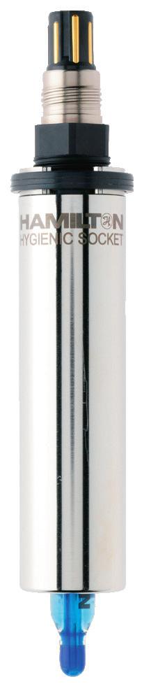

1 Hygienic Socket
2 TABLE OF CONTENTS Table of contents en Hamilton Warranty Please refer to the General Terms of Sales (GTS). Important note Copyright 2018 Hamilton Bonaduz AG, Bonaduz Switzerland. All rights reserved. The reproduction of any part of this document in any form is forbidden without the express written agreement of Hamilton Bonaduz AG. Contents of this manual can be modified without previous announcement. Technical modifications reserved. Greatest possible care was used on the correctness of the information in this manual. If errors should be discovered nevertheless, Hamilton Bonaduz AG is pleased to be informed about it. Regardless of this, Hamilton Bonaduz AG cannot assume liability for any errors in this manual or for their consequences. 1 Introduction Safety instructions General safety instructions Intended use Basic safety Other risks Transportation and storage Description of the Hygienic Socket Assembly General Mounting the Hygienic Socket Assembling the Armature Operation The «Life Guard» feature Cleaning and maintenance General cleaning information Cleaning in place (CIP) Cleaning the interior of the Hygienic Socket Care of O-rings Maintenance Ordering information Accessories Technical Data...16 Inhaltsverzeichnis...19 de Hygienic Socket Manual 3
3 INTRODUCTION SAFETY INSTRUCTIONS 1 Introduction This manual is for the Hygienic Socket, developed especially for hygienic processes. The following versions of the Hygienic Socket are available: ATTENTION! Everyone involved in the operation and maintenance of a Hygienic Socket must carefully read and follow these operating instructions. Your personal safety may be at stake. Ref Name Hygienic Socket Hygienic Socket Hygienic Socket Hygienic Socket ATTENTION! The process pressure of 16 bar, and the process temperature of 140 C, must in no circumstances be exceeded. ATTENTION! The Hygienic Socket must be maintained according to the instructions given in Section 7.5, «Maintenance». Hygienic Sockets are quality products, produced in accordance with the latest scientific and technical findings. Follow the instructions given here to ensure maximum safety and product longevity. These instructions must be read, understood, and followed by all staff using the device. Hamilton assumes no responsibility for damage and/or operational disruption arising from failure to observe these instructions. 2 Safety instructions 2.1 General safety instructions Hygienic Sockets and their parts are built using state-of-the-art technology, and are safe to operate. However, there can be risk to life and limb if users do not operate them correctly and appropriately. A Hygienic Socket must only be used: For its intended purpose When in optimum condition The maximum process temperature permitted is limited not only by the Hygienic Socket itself, but also by the sensor installed in the Hygienic Socket. For this reason, always check the temperature specifications of the sensor to determine the maximum operating temperature. Other relevant regulations must be complied with. These include, in particular: Regulations regarding safety and health protection in preparing materials and their use in the workplace Machine Directive Other national regulations Accident prevention regulations Any other relevant DIN and VDE directives 2.2 Intended use Hygienic Sockets are designed for specific operating conditions (see Section 6) with respect to temperature, pressure, and mounting. Intended use also includes conformity with the conditions set down by Hamilton for assembly, disassembly, initial operation, operation, and maintenance. Any other or further use is classified as unintended, and Hamilton accepts no responsibility for any ensuing damage. Hygienic Socket Manual 5
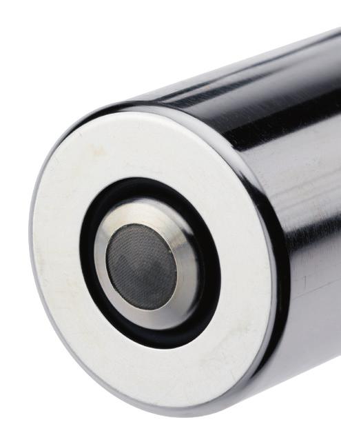
4 SAFETY INSTRUCTIONS TRANSPORTATION AND STORAGE 2.3 Basic safety 3 Transportation and storage Danger of explosion Where maintenance, assembly, or service work is needed on the Hygienic Socket, ensure that no potentially explosive atmosphere arises. Installation, initial operation, cleaning, maintenance, trouble shooting Prescribed maintenance and inspection tasks must be completed at the appropriate intervals, as given in Section 7.5, Maintenance. Operators must be informed before the start of maintenance and servicing. Secure all system parts and media, connected to the Hygienic Socket against accidental process start-up. Sensors in the Hygienic Socket must be dismantled only in a de-pressurized condition. Defective parts must be replaced immediately. Use only original spare parts. There is no guarantee that parts from other manufacturers meet the operational and safety requirements of the Hygienic Socket. On completing maintenance, check that the inside of the Hygienic Socket is clean, and that none of the Life-Guard boreholes are clogged or covered (such as by a cleaning adapter). Always do the following: Check the Hygienic Socket package for completeness immediately after receipt. Notify in writing, without delay, any damage in transit or any missing parts. When returning a Hygienic Socket to a Hamilton partner, make sure it is in its original packaging. During storage protect the Hygienic Socket from moisture, direct heat sources (sun, heaters), contamination, and mechanical impact. 4 Description of the Hygienic Socket The Hygienic Socket was developed especially for applications in biotechnology and pharmaceutical industry with stringent requirements for hygienic behavior. 2.4 Other risks SEAL PUSHER STEEL SLEEVE ATTENTION! Even after all necessary safety measures have been complied with, there remains a risk of leaks or mechanical damage to the Hygienic Socket. In any place where there are seals or screws, there is the potential for gases or liquids to leak out undetectedly. O-RING O-RING SLEEVE (contains O-ring) «LIFE-GUARD» BOREHOLE (also accepts cleaning adapter) BOREHOLES PG13,5 THREAD Hygienic Socket Manual 7

5 ASSEMBLY ASSEMBLY 5 Assembly 5.1 General Electrical connections must be made only by qualified personnel. Hamilton accepts no responsibility for damage resulting from incorrect assembly work by third parties. If a Hygienic Socket is modified, Hamilton does not accept liability, and does not provide any further guarantee for the Hygienic Socket. 5.2 Mounting the Hygienic Socket The steel sleeve must be welded into a circular cut-out of appropriate size (28 mm diameter) at its place of use. Installation depth can be 0 to 55 mm. 73 mm 0 to ~ 55 mm 1. Only an experienced welding specialist should carry out the welding. 2. It is recommended to do a test weld to find out if the planned welding procedure is appropriate and the seal between Hygienic Socket and sensor is tight. If not, the welding procedure needs to be optimized and be approved again. 3. Flush welding of the hygienic Socket to the exposed metal surface is only possible with very thin plates (< 4 mm). For thicker metal plates it is recommended that the Hygienic Socket protrudes at least 25 mm past the surface. 4. Preparation of the welding groove (Double HV or K groove): COVER PASS a. Hole diameter: mm ROOT PASS b. Chamfer of plate: ~1 mm c. Thickness of root face around 1 mm 5. The heat input and arc energy of the welding process should be minimized to keep the temperature as low as possible to prevent deformation of the sealing flange. This can be achieved by a combination of the following procedures: SEALING FLANGE a. Cooling with forming gas (e.g. Argon) b. Segmented welding (see figure 2): 1. Welding fo the root pass: i. Welding of the first section (1) ii. Welding of the opposite section (2) iii. Cooling phase iv. Welding of section 3 v. Welding of section 4 2. Welding of hot, fill and cover passes depending on plate thickness: For every subsequent pass apply the same procedure as for the root pass c. Cooling with compressed air after each welding section. d. Welding with a welding current as small as possible, possibly by pulsed welding HYGIENIC SOCKET WALL Ø mm Figure 1 WALL Hygienic Socket with sensor, mounted in wall The Hygienic Socket has optimized geometry between the sensor, O-ring, and internal sealing flange to provide a smooth, flush interface ideal for use in hygienic processes. Too much heat from the welding process can deform the sealing flange and may lead to poor sealing of the sensor. Due to this potential issue, the following points need to be observed: Figure Hygienic Socket Manual 9

6 ASSEMBLY OPERATION 5.3 Assembling the Armature 6 Operation NOTE: The Hygienic Socket is intended only for mounting sensors with a shaft length of 120 mm. In EU countries, initial operation of the Hygienic Socket is permitted only when it has been verified that the Hygienic Socket conforms to the requirements of the EC directive on machines, the harmonized norms, the European norms, or the corresponding national norms. After the welded area has cooled down, do the following: 1. Ensure there is no damage to the sensor or the Hygienic Socket. 2. Check that all O-rings are in place in their appropriate grooves, and are free of damage. 3. Insert the seal pusher, and screw the sensor into the PG13,5 thread (locking torque see below). 4. Tightness of the installation must be verified. When a sensor is screwed into the Hygienic Socket, the seal pusher presses the O-ring into the space between the steel sleeve and the sensor shaft. This seals the sensor in a manner that almost completely eliminates crevices and their associated risk of contamination. When the sensor is loosened, the O-ring relaxes again. This lowers the friction between the O-ring and the other parts of the assembly, and the process is no longer sealed. If this takes place while the process is still under pressure, the Life Guard feature, explained below, with help to detect it. Before initial operation of the Hygienic Socket: Ensure that the seal is tight. Ensure that all parts are in working order. In addition to initial operation, perform the above checks: Immediately following any breakdown. When the device has been out of use for a long period. After repairs or maintenance. ATTENTION! Contact with salt solutions and concentrated acids can result in corrosion. Maximum process temperature: 140 C Maximum process pressure: 16 bar Tip of a Hygienic Socket with loose sensor: the O-ring is not under pressure. O-RING SENSOR TIP SEALING FLANGE Tip of a Hygienic Socket with tightened sensor: the O-ring, under pressure, creates a seal with no crevices. Recommended locking torque is 2 Nm (this is equivalent to a force of 10 N applied to the end of a 20 cm long spanner). 6.1 The «Life Guard» feature The Hygienic Socket is equipped with a safety mechanism, the so-called Life Guard boreholes, to prevent danger to personnel. If the sensor is unscrewed while there is still pressure in the process, the O-ring between the sensor and the steel sleeve of the Hygienic Socket loses its seal. In this case, process medium enters the Hygienic Socket and exits through the Life Guard boreholes (thereby alarming and protecting personnel) before the sensor is loosened entirely. Fluid dripping from the cleaning/ Life-Guide boreholes in the sleeve indicates that there is still pressure in the process. In this case, the sensor can be tightened again until such time as the process is no longer under pressure. Then the sensor can be safely removed. Hygienic Socket Manual 11
7 CLEANING AND MAINTENANCE CLEANING AND MAINTENANCE Another advantage of the life guard feature is the control of the O-ring. If an O-ring is missing or broken during the process eventhough the sensor is mounted it will be shown because process medium will exit through the Life Guard boreholes. CLEANING ADAPTER, FOR EXAMPLE INLET 7 Cleaning and maintenance Observe the general safety precautions given in these operating instructions when carrying out all maintenance, cleaning and servicing. Both operational safety and the life expectancy of the Hygienic Socket are depending on appropriate maintenance and servicing, among other factors. 7.1 General cleaning information CLEANING ADAPTER, FOR EXAMPLE OUTLET The Hygienic Socket can be cleaned with standard cleaning agents. Never use scouring agents containing hard particles. Cleaning or steam-sterilizing the Hygienic Socket is possible by means of cleaning adapters inserted into the boreholes. 7.2 Cleaning in place (CIP) If the installation into which the sensor is built is being cleaned, the parts of the Hygienic Socket and of the sensor that are normally in contact with the medium (now in contact with the cleaning liquid) can be cleaned in place, together with the rest of the installation. 3 mm Ø 5 mm 7.3 Cleaning the interior of the Hygienic Socket If the space between sensor and sleeve in the interior of the Hygienic Socket becomes contaminated, it can be cleaned easily by fitting cleaning adapters (not supplied by Hamilton) to the (non-threaded) boreholes in the wall of the steel sleeve, and injecting a suitable cleaning fluid. Alternatively, the Hygienic Socket can be steam sterilized. Ø 4 mm Dimensions of a borehole for cleaning adapters (dimensions shown in millimetres). Hygienic Socket Manual 13

8 CLEANING AND MAINTENANCE ORDERING INFORMATION 7.4 Care of O-rings Check the O-rings regularly. When mounting a new O-ring, take care not to damage it, as a perfect seal can not be guaranteed with a damaged O-ring. To replace the front O-ring, forcefully pull the sleeve from the Seal Pusher, then replace the O-ring and push the sleeve back onto the Seal Pusher. Clean the Hygienic Socket by means of the Life Guard boreholes, in case of contamination by the medium. Thoroughly clean the interior of the Hygienic Socket and the seal pusher after sensor breakage. Replace O-rings. 8 Ordering information Hamilton bears no responsibility for damage arising from the use of non-original spare parts; this will void warranty. SLEEVE O-RING (inside the sleeve) 8.1 Accessories Seal Pusher with O-ring sleeve removed. The O-ring can now be easily removed out of the sleeve. After high temperature cycles (100 to 140 C) replace the O-ring each time the sensor is unscrewed. This is because the compression set of EPDM must be considered (DIN ISO 815, the deviation of the original O-ring form over time, due to high temperature and pressure). Replace O-rings at least once a year. 7.5 Maintenance By default, Hygienic Sockets with Refs , and are delivered with EPDM O-rings, Hygienic Socket is delivered with FFKM O-rings. O-rings of other materials are available on request. DO Adapter (Ref ) is useful for mounting 120 mm oxygen or conductivity sensores, but only for sensors with a shaft diameter of 12 mm throughout the entire a-length. The DO Adapter may not be used for ph sensors or the Conducell UPW. Tightness of the installation after sensor mounting must be verified. The adapter is screwed onto the Hygienic Socket, and the sensor into the adapter. When in place, the sensor tip is almost flush with the Hygienic Socket, leading to excellent cleanability. Qualified personnel must draw up and implement a maintenance plan for the Hygienic Socket, according to the requirements of the installation. SENSOR TIP AND HYGIENIC SOCKET ALMOST FLUSH Special attention must be given in the maintenance plan to the O-rings. O-rings used in Hygienic Sockets are consumable parts, and their life expectancy depends on process conditions. If the temperature frequently exceeds 100 C, the O-rings must be replaced each time the sensor is unscrewed, because they are easily deformed under conditions of high temperature. If replacement of O-rings according to the plan is not followed, leakage can occur. Check and replace O-rings as required; always replace at least once a year. Make sure the sensor is screwed in firmly the PG13,5 thread. (Weekly check recommended.) Perform CIP cleaning according to process requirements. SENSOR HEAD DO ADAPTER HYGIENIC SOCKET Hygienic Socket Manual 15
9 TECHNICAL DATA TECHNICAL DATA ATTENTION! The DO adapter must not be used with ph sensors or the Conducell UPW. Seal Pusher Kits can be ordered separately (containing the Seal Pusher with EPDM O-rings which is put into the steel mantle). Description Ref Hamilton DO Adapter Replacement Seal Pusher Kit for Hygienic Socket O-ring Set EPDM (10 O-rings of each size) O-ring Set FPM (10 O-rings of each size) O-ring Set SILICONE (10 O-rings of each size) O-ring Set FFKM (2 O-rings of each size) Ref Steel sleeve material DIN / SS 316 L Seal Pusher material Stainless Steel V4A Temperature range C Max. pressure 16 bar O-ring material EPDM (factory standard) Ref Steel sleeve material DIN / SS 316 L Seal Pusher material Stainless Steel V4A Temperature range C Max. pressure 16 bar O-ring material EPDM (factory standard) 9 Technical Data Ref Steel sleeve material DIN / SS 316 Ti Seal Pusher material Stainless Steel V4A Temperature range C Max. pressure 16 bar O-ring material EPDM (factory standard) Ref / / / Length 107 mm Diameter 28 mm This drawing is valid for Hygienic Socket of all Ref numbers. Hygienic Socket differ in the material of which the steel mantle is made, but not in their dimensions. Ref Steel sleeve material DIN / Alloy C-22 Seal Pusher material Stainless Steel V4A Temperature range C Max. pressure 16 bar O-ring material FFKM (factory standard) Hygienic Socket Manual 17
10 INHALTSVERZEICHNIS Inhaltsverzeichnis de 1 Einleitung Sicherheitshinweise Allgemeine Sicherheitshinweise Bestimmungsgemässe Verwendung Grundlegende Sicherheitshinweise Restgefahren Transport und Lagerung Beschreibung des Hygienic Socket...23 Hamilton Garantie Bitte beachten Sie die allgemeinen Geschäfts bedingungen (AGB). Wichtiger Hinweis Copyright 2018 Hamilton Bonaduz AG, Bonaduz Schweiz. Alle Rechte vorbehalten. Die Reproduktion irgendeines Teils dieses Dokuments in jeder beliebigen Form ist ohne die ausdrückliche schriftliche Zustimmung der Hamilton Bonaduz AG untersagt. Der Inhalt dieses Handbuchs kann ohne vorherige Ankündigung geändert werden. Technische Änderungen vorbehalten. Es wurde größtmögliche Sorgfalt auf die Richtigkeit der Informationen in diesem Handbuch verwendet. Sollten dennoch Fehler entdeckt werden, würde sich die Hamilton Bonaduz AG freuen, darüber informiert zu werden. Ungeachtet dessen kann die Hamilton Bonaduz AG keine Haftung für etwaige Fehler in diesem Handbuch oder deren Folgen übernehmen. 5 Montage Allgemeines Montage des Hygienic Socket Montage des Sensors Betrieb Life-Guard-Funktion Reinigung und Wartung Allgemeine Informationen zur Reinigung Reinigung während der Anlagenreinigung (CIP) Reinigung des Inneren des Hygienic Socket Pflege der O-Ringe Regelmässige Wartungsarbeiten Bestellinformationen Zubehör Technische Daten...32 Hygienic Socket Bedienungsanleitung 19
11 EINLEITUNG SICHERHEITSHINWEISE SICHERHEITSHINWEISE 1 Einleitung Diese Betriebsanleitung bezieht sich auf den Hygienic Socket, der insbesondere für hygienische Prozesse entwickelt wurde. Folgende Ausführungsformen des Hygienic Socket sind verfügbar: WARNUNG! Alle Personen, die mit der Inbetriebnahme, der Bedienung und der Wartung des Hygienic Socket zu tun haben, müssen diese Bedienungsanleitung aufmerksam lesen und beachten. Es geht um Ihre Sicherheit! Ref Name Hygienic Socket Hygienic Socket Hygienic Socket Hygienic Socket WARNUNG! Der Prozessdruck von 16 bar und die Prozesstemperatur von 140 C dürfen in keinem Falle überschritten werden. WARNUNG! Der Hygienic Socket muss entsprechend der Instruktionen in Kapitel 7.5, «Regelmässige Wartungsarbeiten», gewartet werden. Hygienic Sockets sind nach neuesten technischen und wissenschaftlichen Erkenntnissen hergestellte Qualitätsprodukte. Bei genauer Beachtung der nachstehenden Hinweise erreichen Sie ein Höchstmass an Sicherheit und Lebensdauer. Diese Betriebsanleitung muss vom zuständigen Personal gelesen, verstanden und beachtet werden. Für Schäden und Betriebsstörungen, die sich aus Nichtbeachten der Betriebsanleitung ergeben, übernimmt die Firma Hamilton keine Haftung. 2 Sicherheitshinweise 2.1 Allgemeine Sicherheitshinweise Hygienic Socket sowie deren Ausrüstungsteile sind nach dem neuesten Stand der Technik gebaut und betriebssicher. Dennoch drohen bei Fehlbedienung oder Missbrauch Gefahren für Leib und Leben des Bedieners. Der Hygienic Socket ist nur zu benutzen: Für die bestimmungsgemässe Verwendung. In einwandfreiem Zustand. Die maximal zulässige Prozesstemperatur wird nicht nur durch den Hygienic Socket limitiert, sondern auch durch den Sensor, der in den Hygienic Socket eingebaut ist. Überprüfen Sie deshalb anhand der Spezifikationen des Sensors, wie die maximal zulässige Prozesstemperatur definiert ist. Weiter sind sämtliche einschlägigen Vorschriften zu beachten. Dazu gehören insbesondere: Verordnung über Sicherheit / Gesundheitsschutz bei der Bereitstellung von Arbeitsmitteln und deren Benutzung bei der Arbeit. Maschinenrichtlinie. Sonstige nationale Vorschriften. Unfallverhütungsvorschriften (UVV). Sonstige gültige DIN und VDE Richtlinien. 2.2 Bestimmungsgemässe Verwendung Hygienic Sockets sind nur für bestimmte Betriebs-verhältnisse (siehe Kapitel 6) hinsichtlich Temperatur, Druck und Einbau vorgesehen. Zur bestimmungsgemässen Verwendung gehört auch die Einhaltung der von Hamilton vorgeschriebenen Bedingungen für Montage, Demontage, Inbetriebnahme, Betrieb und Instandhaltung. Für andere oder darüber hinausgehende Schäden haftet Hamilton nicht. Hygienic Socket Bedienungsanleitung 21
12 SICHERHEITSHINWEISE TRANSPORT UND LAGERUNG 2.3 Grundlegende Sicherheitshinweise 3 Transport und Lagerung Explosionsgefahr Bei allen anfallenden Wartungs-, Montage- und Instandhaltungsarbeiten am Hygienic Socket muss sichergestellt werden, dass keine explosionsfähige Atmosphäre auftreten kann. Installation, Inbetriebnahme, Reinigung, Wartung, Störungsbeseitigung Vorgeschriebene Wartungs- und Inspektionsarbeiten müssen in angemessenen Abständen durchgeführt werden, wie in Kapitel 7.5, «Regelmässige Wartungsarbeiten», beschrieben. Informieren Sie das Bedienungspersonal vor Beginn der Wartungs- und Instandhaltungsarbeiten. Sichern Sie alle dem Hygienic Socket vor- und nachgeschalteten Anlageteile und Betriebsmedien gegen unbeaufsichtigte Inbetriebnahme ab. Der Ausbau der Sensoren aus dem Hygienic Socket darf nur in drucklosem Zustand erfolgen. Mangelhafte Bauteile sofort austauschen. Nur Originalersatzteile verwenden. Bei fremdbezogenen Teilen ist nicht gewährleistet, dass sie den Betriebs- und Sicherheitserfordernissen des Hygienic Socket genügen. Überprüfen Sie nach Beendigung der Wartungsarbeiten, dass das Innere des Hygienic Socket sauber ist, und dass keine der «Life Guard»-Bohrungen verstopft oder verdeckt ist (etwa durch einen Reinigungsadapter). Beachten Sie immer: Die Vollständigkeit der Lieferung des Hygienic Socket ist beim Empfang zu prüfen. Eventuelle Transportschäden und/oder fehlende Teile sind sofort schriftlich zu melden. Wenn Sie den Hygienic Socket zum Hamilton-Händler zurücksenden, stellen Sie sicher, dass sich der Hygienic Socket in der Originalverpackung befindet. Während der Lagerung ist der Hygienic Socket vor Nässe, direkter Wärmeeinwirkung (Sonne, Heizung), Verschmutzung sowie mechanischen Einflüssen zu schützen. 4 Beschreibung des Hygienic Socket Der Hamilton Hygienic Socket ist insbesondere für Anwendungen in der Biotechnologie und Pharmaindustrie entwickelt worden, die hohe Anforderungen an die Hygiene stellen. SEAL PUSHER STAHLMANTEL 2.4 Restgefahren WARNUNG! Auch wenn alle notwendigen Sicherheitsmassnahmen getroffen wurden, besteht eine Restgefahr durch Undichtigkeiten oder mechanische Schäden am Hygienic Socket. An Dichtungen oder Verschraubungen können Gase oder Flüssigkeiten unkontrolliert austreten. O-RING BOHRUNGEN O-RING-KRALLE (enthält O-Ring) PG13,5 GEWINDE «LIFE-GUARD»-BOHRUNG (auch zum Anschluss von Reinigungsadaptern) Hygienic Socket Bedienungsanleitung 23
13 MONTAGE MONTAGE 5 Montage 5.1 Allgemeines Elektrische Anschlüsse sind ausschliesslich von qualifiziertem Fachpersonal zu erstellen. Für Schäden infolge unsachgerechter Ausführung der Montagearbeiten durch Fremdpersonal übernimmt Hamilton keine Haftung. Mit einer Modifikation des Hygienic Socket entfällt jegliche Haftung seitens Hamilton und Hamilton leistet keine weitere Garantie für den Hygienic Socket. 5.2 Montage des Hygienic Socket Der Stahlmantel muss in eine Öffnung passender Grösse (28 mm Durchmesser) an seinem Bestimmungsort eingeschweisst werden. Hierbei lässt sich die Einbautiefe zwischen 0 und 55 mm variieren. 73 mm 0 bis ~ 55 mm Folgende Punkte sollten beachtet werden: 1. Nur ein erfahrener Schweissfachmann soll das Einschweissen vornehmen 2. Allenfalls ist vor dem ersten Einschweissen eine Testschweissung vorzunehmen, um zu prüfen, ob der mit dem vorgesehenen Schweissverfahren eingeschweisste Hygienic Socket zum Sensor noch dicht ist. Falls nicht, ist das Schweissverfahren zu optimieren und allenfalls erneut zu überprüfen. 3. Frontbündiges Einschweissen ist nur möglich bei ganz dünnen Blechen (< 4 mm). Bei dickeren Blechen ist ein Vorstehen des Sockets ab 25 mm empfehlenswert. 4. Vorbereitung der Einschweissbohrung gemäss Bild 1 (Doppel-HV- oder K-Naht): DECKLAGE a. Durchmesser: mm WURZELLAGE b. Facettierung: ~1 mm c. Steghöhe ca. 1 mm 5. Der Energieeintrag beim Schweissen soll minimiert werden und die Temperatur an der Dichtlippe des Sockets soll möglichst tief bleiben, was durch eine geschickte Kombination folgender Vorgehensweisen erfolgen soll: DICHT- LIPPE a. Kühlen mit Formiergas (z.b. Argon) b. Sektorielles Schweissen (Bild 2): 1. Schweissen der Wurzellage i. Schweissen des ersten Sektors (1) ii. Schweissen des gegenüberliegenden Sektors (2) iii. Abkühlphase iv. Schweissen des Sektors 3 v. Schweissen des Sektors 4 2. Sektorielles Schweissen weiterer Fülllagen, in Abhängikeit von der Blechdicke, sowie der Decklage: Vorgehen wie bei der Wurzellage beschrieben c. Kühlen mit Pressluft nach jedem Schweisssektor d. Schweissen mit möglichst kleinem Schweissstrom, evtl. Pulsschweissen HYGIENIC SOCKET WAND Ø mm Bild 1 WAND In eine Wand eingeschweisster Hygienic Socket mit Sensor. Der Hygienic Socket besitzt eine für hygienische Anwendungen optimierte Geometrie der Dichtlippe zum Sensor und des dazugehörenden O-Rings. Die Form der dünnen Dichtlippe darf nicht durch zu grossen Wärmeeintrag beim Schweissprozess deformiert werden, da sonst die Dichtigkeit zum Sensor nicht mehr garantiert ist Bild 2 Hygienic Socket Bedienungsanleitung 25

14 MONTAGE BETRIEB 5.3 Montage des Sensors 6 Betrieb HINWEIS: Der Hygienic Socket ist nur für die Aufnahme von Sensoren mit der Schaftlänge 120 mm vorgesehen. Die Inbetriebnahme des Hygienic Socket ist in den Ländern der EU solange untersagt, bis festgestellt wurde, dass der Hygienic Socket den Bestimmungen der EG-Richtlinie Maschinen, den harmonisierten Normen, Europanormen oder den entsprechenden nationalen Normen entspricht. Nach Erkalten der Schweissnaht sind folgende Schritte durchzuführen: 1. Stellen Sie sicher, dass keine Beschädigungen am Sensor bzw. am Hygienic Socket vorliegen. 2. Prüfen Sie, ob alle O-Ringe in den vorgesehenen Nuten vorhanden bzw. nicht beschädigt sind. 3. Setzen Sie den Seal Pusher ein und schrauben Sie den Sensor in das PG13,5 Gewinde. 4 Die Dichtigkeit der Installation muss überprüft werden. Sobald ein Sensor in den Hygienic Socket geschraubt wird, presst der Seal Pusher den O-Ring in den Spalt zwischen Stahlmantel und Sensorschaft. Dadurch wird bei der Abdichtung des Sensors zum Prozessmedium hin erreicht, dass fast keine Vertiefungen verbleiben, die schlecht zu reinigen wären. Der O-Ring entspannt sich wieder, sobald der Sensor ein wenig losgeschraubt wird. Dadurch wird die Pressbelastung des O-Rings verringert, und der Prozess ist nicht länger abgedichtet. Wenn das passiert, wenn der Prozess unter Druck steht, kommt automatisch die weiter unten aufgeführte «Life Guard»-Funktion in Verwendung. Bevor Sie den Hygienic Socket in Betrieb nehmen: Stellen Sie sicher, das die Dichtigkeit gewährleistet ist. Stellen Sie sicher, dass alle Teile funktionstüchtig sind. Die Prüfungen sind auch durchzuführen sofort nach jedem Störfall. nach längerem Stillstand. nach Reparatur- bzw. Wartungsarbeiten. WARNUNG! Der Kontakt mit Salzlösungen und konzentrierten Säuren kann Korrosion verursachen. Maximale Prozesstemperatur: 140 C Maximaler Prozessdruck: 16 bar Spitze eines Hygienic Socket mit losem Sensor: Der O-Ring ist entspannt. O-RING SENSORSPITZE DICHTLIPPE Spitze eines Hygienic Socket mit festgezogenem Sensor: Der O-Ring wird angepresst und dichtet spaltfrei. Empfohlenes Anzugsdrehmoment am Sensor: 2 Nm (Dies entspricht einer Kraft von 10 N am Ende eines 20 cm langen Gabelschlüssels). 6.1 Life-Guard-Funktion Um eine Gefährdung des Personals zu vermeiden, verfügt der Hygienic Socket über einen Sicherheitsmechanismus, die sogenannten «Life Guard»-Bohrungen: Falls der Sensor losgeschraubt wird, wenn noch Druck anliegt, dichtet der O-Ring zwischen Sensor und Stahlmantel des Hygienic Socket nicht mehr. Prozessmedium gelangt ins Innere des Hygienic Socket und entweicht durch die «Life Guard»-Bohrungen nach aussen (dadurch wird das Personal alamiert und geschützt), noch bevor der Sensor völlig herausgeschraubt ist. Aus den «Life Guard»-Bohrungen heraustropfende Flüssigkeit zeigt an, dass noch Druck im Prozess anliegt. In diesem Fall kann der Sensor wieder festgezogen werden, bis der Prozess drucklos ist und der Sensor sicher entfernt werden kann. Hygienic Socket Bedienungsanleitung 27

15 REINIGUNG UND WARTUNG REINIGUNG UND WARTUNG Ein anderer Vorteil der «Life-Guard»-Bohrungen ist die Kontrolle des O-Rings während des Prozesses. Ist kein O-Ring vorhanden oder wird ein O-Ring während des Prozesses undicht, auch wenn ein Sensor eingebaut ist, so wird dies angezeigt, da Prozessmedium über die «Life Guard»-Bohrungen austritt. REINIGUNGSADAPTER, Z.B. EINLASS 7 Reinigung und Wartung Bei allen Wartungs-, Reinigungs- und Instandhaltungsarbeiten sind die allgemeinen Sicherheitsanweisungen dieser Betriebsanleitung zu beachten. Die Betriebssicherheit und die Lebensdauer des Hygienic Socket sind neben mehreren Faktoren auch von der ordnungsgemässen Wartung und Instandsetzung abhängig. REINIGUNGSADAPTER, Z.B. AUSLASS 7.1 Allgemeine Informationen zur Reinigung Der Hygienic Socket kann mit den üblichen Reinigungsmitteln gereinigt werden. Scheuermittel sind ungeeignet. Reinigung oder Dampfsterilisierung des Hygienic Socket ist durch Reinigungsadapter möglich, die in die Bohrungen eingeführt werden. 7.2 Reinigung während der Anlagenreinigung (CIP) Ø 5 mm Ist die Anlage, in die der Sensor eingebaut ist, in Betrieb, so werden die prozessberührten Teile des Hygienic Socket und des Sensors zusammen mit dem Rest der Anlage in-line gereinigt. 3 mm 7.3 Reinigung des Inneren des Hygienic Socket Wenn der Raum zwischen Sensor und Stahlmantel im Inneren des Hygienic Socket verunreinigt ist, kann dieser leicht durch Reinigungsadapter (nicht von Hamilton geliefert) durch die Bohrlöcher (ohne Gewinde) in der Wand des Stahlmantels gereinigt werden. Man kann so auch dampfsterilisieren. Ø 4 mm Abmessungen eines Bohrlochs für Reinigungsadapter in mm. Hygienic Socket Bedienungsanleitung 29

16 REINIGUNG UND WARTUNG BESTELLINFORMATIONEN 7.4 Pflege der O-Ringe Kontrollieren Sie die O-Ringe regelmässig. Beim Ersatz beschädigter O-Ringe darf der neue O-Ring mechanisch nicht verletzt werden, da sonst die Dichtfunktion nicht mehr gewährleistet ist. Den «Front-O-Ring» wechselt man am besten, indem man die Kralle samt O-Ring nach vorne vom Seal Pusher abzieht (kräftig ziehen!) und dann den O-Ring wechselt. Danach den Seal Pusher wieder in den Mantel zurück schieben. Reinigung des Hygienic Socket über die «Life Guard»-Bohrungen im Falle von Verschmutzung durch Prozessmedium. Bei Sensorbruch ist die Innenseite des Hygienic Socket und der Seal Pusher komplett zu reinigen und die O-Ringe müssen gewechselt werden. 8 Bestellinformationen Für Schäden, die durch die Verwendung von nicht Original-Ersatzteilen entstehen, ist jede Haftung und Gewährleistung seitens Hamilton ausgeschlossen. KRALLE O-RING (innerhalb der Kralle) 8.1 Zubehör Seal Pusher mit abgezogener O-Ring-Kralle. Der O-Ring lässt sich nun einfach aus der Kralle herausholen. Bei hohen Temperaturzyklen ( C) ist der O-Ring bei jedem Sensorausbau zu wechseln, da der Druckverformungsrest bei EPDM nicht zu vernachlässigen ist (DIN ISO 815, die Abweichung von der ursprünglichen O-Ring-Form nach hoher Druck- und Temperaturbelastung). O-Ringe müssen mindestens einmal im Jahr getauscht werden. 7.5 Regelmässige Wartungsarbeiten Standardmässig werden die Hygienic Sockets mit den Artikelnummern , und mit EPDM O-Ringen ausgeliefert, der Hygienic Socket mit FFKM O-Ringen. Es können jedoch O-Ringe aus anderen Materialien bestellt werden. Ein DO Adapter (242538) ist für die Montage von 120 mm Sauerstoff- oder Leitfähigkeitssensoren vorteilhaft. Er wird aber nur dann verwendet wenn der Sensor einen Schaftdurchmesser von 12 mm über die gesamte a-länge besitzt. Der DO Adapter kann nicht verwendet werden zum Beispiel bei ph-sensoren oder der Conducell UPW. Die Dichtigkeit des System muss nach einer Sensorinstallation überprüft werden. Der Adapter wird auf den Hygienic Socket aufgeschraubt, und der Sensor wird darin befestigt. Dadurch schliesst die Sensorspitze beinahe bündig mit dem Hygienic Socket ab. Ein Wartungsplan ist von qualifizierten Personen zu erstellen und zu überwachen, um Risiken zu vermeiden, entsprechend der jeweiligen Applikationsbedingungen. SENSORENSPITZE UND HYGIENIC SOCKETTM BEINAHE BÜNDIG Im Wartungsplan muss besonders auf die O-Ringe geachtet werden. Die im Hygienic Socket verwendeten O-Ringe unterliegen einem Verschleiss, und ihre Lebenserwartung hängt von den Betriebsbedingungen ab, unter denen sie verwendet werden. Wenn die Temperatur häufig 100 C übersteigt, sind die O-Ringe jedes Mal zu wechseln, wenn der Sensor losgeschraubt wird, da die O-Ringe unter hohen Temperaturen zu Verformungen neigen. Wenn die O-Ringe nicht gemäss dem Wartungsplan gewechselt werden, können Leckagen auftreten. Überprüfen der O-Ringe und bei Bedarf austauschen, mindestens nach einem Jahr. Überprüfen, ob der Sensor fest im PG13,5 Gewinde sitzt (wöchentliche Kontrolle empfohlen). CIP-Reinigen gemäss den Erfordernissen des Prozesses. SENSORKOPF DO-ADAPTER HYGIENIC SOCKET Hygienic Socket Bedienungsanleitung 31
.")
17 TECHNISCHE DATEN TECHNISCHE DATEN WARNUNG! Der DO-Adapter darf nicht mit ph-sensoren verwendet werden. Ausserdem kann das «Seal Pusher Kit» nachbestellt werden (enthält den Seal Pusher mit EPDM O-Ringen, der in den Stahlmantel eingesetzt wird). Beschreibung Ref Hamilton DO Adapter Ersatz «Seal Pusher Kit» für Hygienic Socket O-Ring Set EPDM (10 O-Ringe jeder Grösse) O-Ring Set FPM (10 O-Ringe jeder Grösse) O-Ring Set SILIKON (10 O-Ringe jeder Grösse) O-Ring Set FFKM (2 O-Ringe jeder Grösse) Ref Material Stahlmantel DIN / SS 316 L Material Seal Pusher Stainless Steel V4A Temperaturbereich C Max. Druck 16 bar O-Ring-Material EPDM (werksseitig) Ref Material Stahlmantel DIN / SS 316 L Material Seal Pusher Stainless Steel V4A Temperaturbereich C Max. Druck 16 bar O-Ring-Material EPDM (werksseitig) 9 Technische Daten Ref Material Stahlmantel DIN / SS 316 Ti Material Seal Pusher Stainless Steel V4A Temperaturbereich C Max. Druck 16 bar O-Ring-Material EPDM (werksseitig) Ref / / / Länge 107 mm Durchmesser 28 mm Diese Zeichnung gilt für Hygienic Sockets aller Refereznummern. Die Hygienic Sockets unterscheiden sich in dem Material, aus dem der Stahlmantel gefertigt ist. Ref Material Stahlmantel DIN / Alloy C-22 Material Seal Pusher Stainless Steel V4A Temperaturbereich C Max. Druck 16 bar O-Ring-Material FFKM (werksseitig) Hygienic Socket Bedienungsanleitung 33
18 NOTIZEN NOTIZEN Hygienic Socket Bedienungsanleitung 35


19 2018 Hamilton Bonaduz AG. All rights reserved /01 02/2018 Web: USA: Europe: Hamilton Americas & Pacific Rim 4970 Energy Way Reno, Nevada USA Tel: Fax: Hamilton Europe, Asia & Africa Via Crusch 8 CH-7402 Bonaduz, Switzerland Tel: Fax: contact.pa.ch@hamilton.ch To find a representative in your area, please visit
NiteCool TCC-100/RCC-100
 NiteCool TCC-100/RCC-100 Standkühlanlage Parking cooler system Rafraîchisseur d'air Raffrescatore a veicolo fermo Enfriador evaporativo Interieurkoeler Betriebsanweisung Operating Instructions Notice d
Kühlregale für Snacks. Wokingham. Cabinets are located in branch entrance area & fail to maintain correct temperatures.
 Wokingham Kühlregale für Snacks Wokingham Snacking Cabinets Die Kühlregale sind im Eingangsbereich der Geschäftsstelle aufgestellt bringen es nicht fertig, die richtigen Temperaturen zu halten. Cabinets
Assembly Instruction GfS Door Terminal
 Part No.: Assembly Instruction GfS Door Terminal Part No.: 790 000 Safety on doors GfS Door Teminal Part No.: 790 000 INDROTUCTION/SAFETY INSTRUCTION INSTALLATION The GfS Door Terminal is a compact device
A6 Safety Monitoring Device
 A6 Safety Monitoring Device PL 0 10 2.2 Manual Publisher NEW LIFT Steuerungsbau GmbH Lochhamer Schlag 8 D- 82166 Gräfelfing Germany Tel.: +49 (0) 89 / 8 98 66-0 Fax: +49 (0) 89 / 8 98 66-3 00 Doc. No.
auto
 FR DE NL ES IT PT DA NO SV FI EL TR MS ZH KO TH AR FA 1 2 3 1 auto 3.1 4 5 5.1 6 7 8 9 PRÉVTION DES ACCIDTS DOMESTIQUES Pour un enfant, une brûlure même légère peut parfois être grave. Au fur et à mesure
Installation Guide. Circulation set for S-F units. Zirkulationsset für S-F Stationen. Code No. 004U8405
 Installation Guide Circulation set for Zirkulationsset für S-F Stationen iv.788 Code No. 004U8400 iv.484 Code No. 004U8403 iv.789 Code No. 004U8401 iv.487 Code No. 004U8405 English - G If the household
Safety. Operating instructions Pilot burners ZAI, ZKIH DANGER. Contents WARNING CAUTION. Changes to edition Elster GmbH Edition 09.
 03 Elster GmbH Edition 09.3 Translation from the German 0350560 D F NL E DK S N P GR TR C PL RUS H www.docuthek.com Operating instructions Pilot burners, Contents Pilot burners,... Contents... Safety....
ENGLISH 4 DEUTSCH 28
 GB KÖLDGRADER DE ENGLISH Please refer to the last page of this manual for the full list of IKEA appointed After Sales Service Provider and relative national phone numbers. DEUTSCH Auf der letzten Seite
ENGLISH 4 DEUTSCH 30
 RENLIG GB DE ENGLISH 4 DEUTSCH 30 ENGLISH 4 Contents Safety information 4 Safety instructions 5 Product description 7 Control panel 8 Before first use 11 Daily Use 11 Hints and tips 14 Programmes 15 Consumption
Multi Channel Potentiostat for testing the resistance to cathodic disbonding acc. ASTM G-8, ASTM G-42, DIN EN ISO 15711, DIN 30670
 Multi Channel Potentiostat for testing the resistance to cathodic disbonding acc. ASTM G-8, ASTM G-42, DIN EN ISO 15711, DIN 30670 Principle of testing cathodic disbonding The CD Test Unit can be used
ENGLISH 4 DEUTSCH 30
 GB HYGIENISK DE ENGLISH Please refer to the last page of this manual for the full list of IKEA appointed After Sales Service Provider and relative national phone numbers. DEUTSCH Auf der letzten Seite
ADSDUDPTB Mounting Base
 ADSDUDPTB Mounting Base Installation Guide Figure 1. ADSDUDPTB Mounting Base Warnings and Cautions Please review the following warnings and cautions before you install the mounting base. For additional
ENGLISH 4 DEUTSCH 29
 GB RENODLAD DE ENGLISH Please refer to the last page of this manual for the full list of IKEA appointed After Sales Service Provider and relative national phone numbers. DEUTSCH Auf der letzten Seite dieser
ENGLISH 4 DEUTSCH 23
 SUPERBT GB DE ENGLISH 4 DEUTSCH 23 ENGLISH 4 Contents Safety instructions 4 Product description 7 First use 11 Daily use 11 Helpful hints and tips 14 Care and cleaning 15 Subject to change without notice.
Manual Isolating Barrier D461R1 (Revision 01)
") D461R1 Manual Isolating Barrier D461R1 (Revision 01) Product Manual Original Instructions valid for models D461R1.11 with 1x signal input into 1x isolated signal output D461R1.12 with 1x signal input into
D461R1 Manual Isolating Barrier D461R1 (Revision 01) Product Manual Original Instructions valid for models D461R1.11 with 1x signal input into 1x isolated signal output D461R1.12 with 1x signal input into
ENGLISH 4 DEUTSCH 27
 GB MIRAKULÖS DE ENGLISH Please refer to the last page of this manual for the full list of IKEA appointed After Sales Service Provider and relative national phone numbers. DEUTSCH Auf der letzten Seite
Einsatz optimierter Glasfaser-verstärkter PP-Produkte, Ingenieurtechnische Zielstellungen und Anforderungen an UL-Standards
 Einsatz optimierter Glasfaser-verstärkter PP-Produkte, Ingenieurtechnische Zielstellungen und Anforderungen an UL-Standards Thomas Mecklenburg; Basell Polyolefine GmbH, 65926 Frankfurt Underwriters Laboratories
Operation Manual Bedienungsanleitung
 Operation Manual Bedienungsanleitung Electrical Chicken Rotisseries Hähnchengrill Elektro CRE2, CRE3, CRE4, CRE5, CRE6 To avoid the risk of accidents or damage to the appliance it is essential to read
ENGLISH 4 DEUTSCH 29
 GB FROSTKALL DE ENGLISH 4 DEUTSCH 29 ENGLISH 4 Contents Safety information 4 Safety instructions 5 Installation 7 Product description 9 Operation 10 Daily Use 14 Hints and tips 18 Care and cleaning 19
MANUAL LAL-SRW3 WARNING DEVICE WARNANLAGE SYSTÈME D'ALARME ALARMSYSTEM. По вопросам продаж и поддержки обращайтесь:
 PROCESS AUTOMATION MANUAL LAL-SRW3 EN WARNING DEVICE DE WARNANLAGE FR SYSTÈME D'ALARME DA ALARMSYSTEM По вопросам продаж и поддержки обращайтесь: Архангельск (8182)63-90-72 Астана +7(7172)727-132 Белгород
ENGLISH 4 DEUTSCH 16
 LAGAN GB DE HGC3K ENGLISH Please refer to the last page of this manual for the full list of IKEA appointed After Sales Service Provider and relative national phone numbers. DEUTSCH Auf der letzten Seite
ENGLISH 4 DEUTSCH 27
 RENLIG GB DE IWM60 ENGLISH 4 DEUTSCH 27 ENGLISH 4 Contents Safety information 4 Safety instructions 5 Product description 7 Control panel 8 First use 10 Daily use 10 Hints and tips 13 Subject to change
dekopin Magnetic Panels
 Product Data Sheet Version: 03ZT18 Langenthaler Str. 4 69434 Hirschhorn/Neckar Germany Tel. +49 (0) 6272-689-0 Fax +49 (0) 6272-6893-0 dekopin Magnetic Panels Product Description The dekopin product group
Manual Isolating Barrier D461 (Revision 05)
") D461 Manual Isolating Barrier D461 (Revision 05) Product Manual Original Instructions valid for models D461.11 with 1x signal input into 1x isolated signal output D461.12 with 1x signal input into 2x isolated
D461 Manual Isolating Barrier D461 (Revision 05) Product Manual Original Instructions valid for models D461.11 with 1x signal input into 1x isolated signal output D461.12 with 1x signal input into 2x isolated
Heat Transfer Station
 Operating manual Heat Transfer Station 16.03.2012 Applicable for: HTS PS1 Table of contents V1.0/03.12 1 Foreword... 2 2 Proper operation... 3 3 Basic safety instructions... 3 3.1 Obligations of the user...
Instructions SCHICK ceramic - milling set
 Original Instructions SCHICK ceramic - milling set SCHICK - ceramic - milling set Contents: 1. Application and use 2. General notes Caution! 3. Scope of delivery 4. Description/ Illustration of construction
WELCOME TO THE VE SAMPLE BOOK WILLKOMMEN ZUM VE SAMPLE BOOK
 SAMPLES WILLKOMMEN ZUM VE SAMPLE BOOK Wir freuen uns, dass Du Dich für einen unserer High Class Custom In-Ear Hörer entschieden hast und geben unser Bestes, Dir ein hervorragendes Produkt zu liefern, das
EN Instruction on mounting and use DE Montage- und Gebrauchsanweisung
 EN Instruction on mounting and use DE Montage- und Gebrauchsanweisung EN - Instruction on mounting and use Closely follow the instructions set out in this manual. All responsibility, for any eventual
ENGLISH 4 DEUTSCH 27
 RENLIG GB DE FWM7 ENGLISH 4 DEUTSCH 27 ENGLISH 4 Contents Safety information 4 Safety instructions 5 Product description 7 Control panel 8 Before first use 10 Settings 10 Daily Use 10 Programmes 13 Consumption
THE THAW HAS SET IN. We wanted to create an artistic interpretation of nature. DRO COLLECTION
 THE THAW HAS SET IN DRO COLLECTION Can you capture the fleeting beauty of a dewdrop? You can. But only if you focus on the phenomenon behind it, explain 13&9 Design. The hydrophobic effect that lets water
Sensor module. Operating instructions. Sensor module, Type 17-51P2-... Document No P2-7D0001 Version: 17 May 2011/Rev. 0
 Sensor module Operating instructions Sensor module, Document No. 11-51P2-7D0001 Version: 17 May 2011/Rev. 0 Operating Instructions Sensor-Module Type: 17-51P2-. Document no.: 11-51P2-7D0001 Version: 17.
Always there to help you
 Always there to help you Register your product and get support at www.philips.com/welcome Question? Contact Philips AC086 User manual 3 Benutzerhandbuch 37 Mode d emploi 75 Қолданушының нұсқасы 111 Руководство
Refrigerator Kühlschrank De Koelkast Le Réfrigérateur Saldytuvas - Saldiklis BU 1200 HCA BU 1201
 Refrigerator Kühlschrank De Koelkast Le Réfrigérateur Saldytuvas - Saldiklis BU 1200 HCA BU 1201 Please read this manual first! Dear Customer, We hope that your product, which has been produced in modern
MÖJLIG GB DE DE AT
 MÖJLIG GB DE DE AT ENGLISH Please refer to the last page of this manual for the full list of IKEA appointed After Sales Service Provider and relative national phone numbers. DEUTSCH Auf der letzten Seite
Operating Instruction SCHICK ceramic - milling set
 Georg Schick Dental GmbH Lehenkreuzweg 12 D-88433 Schemmerhofen Telefon 07356/9500-0 Telefax 07356/9500-95 E-Mail info@schick-dental.de Internet www.schick-dental.de Original Operating Instruction SCHICK
TKF 8439 TKF 8439 A TKF 8439 S. Dryer Trockner
 TKF 8439 TKF 8439 A TKF 8439 S Dryer Trockner Read this manual prior to initial operation of the product! Dear Customer, We hope that your product, which has been manufactured in modern facilities and
Integration of a Water Mist System for the critical Life Safety Control System: The Example Dartford Crossing, UK
 Armin Feltmann, FOGTEC Fire Protection, Köln (D) Simon Burras, Applied Industrial Systems Ltd. (AIS), London (GB) Dirk Sprakel, FOGTEC Fire Protection, Köln (D) Kilian Pai, Institute for Applied Fire Safety
ENGLISH 4 DEUTSCH 20
 MÖJLIG GB DE ENGLISH Please refer to the last page of this manual for the full list of IKEA appointed After Sales Service Provider and relative national phone numbers. DEUTSCH Auf der letzten Seite dieser
the Bit More BTA720/BTA730 EN QUICK GUIDE DE KURZANLEITUNG
 the Bit More BTA720/BTA730 EN QUICK GUIDE DE KURZANLEITUNG CONTENTS 2 We recommend safety first 6 Getting to know your new appliance 7 Operating your new appliance 9 Care, Cleaning & Storage At Sage we
BUILT-IN OVEN AND HOB USER'S MANUAL EINBAUOFEN UND KOCHFELD BEDIENUNGSANLEITUNG
 BUILT-IN OVEN AND HOB USER'S MANUAL EINBAUOFEN UND KOCHFELD BEDIENUNGSANLEITUNG GB DE PCV 6 X FCO 607 X FCO 7 XL CANDY HOOVER GROUP S.R.L. Via Privata Eden Fumagalli 007 Brugherio Milano Italy CONTENTS
LAGAN GB DE FR IT FCF186/44
 LAGAN GB DE FR IT FCF186/44 ENGLISH 4 DEUTSCH 17 FRANÇAIS 32 ITALIANO 48 ENGLISH 4 Contents Safety information 4 Operation 6 First use 7 Daily use 7 Helpful hints and tips 8 Care and cleaning 9 Subject
Please read this user manual first! The user manual will help you use the product in a fast and safe way.
 Hladnjak Please read this user manual first! Dear Customer, We hope that your product, which has been produced in modern plants and checked under the most meticulous quality control procedures, will provide
Refrigerator Kühlschrank Réfrigérateur Koelkast Hladilnik
 Refrigerator Kühlschrank Réfrigérateur Koelkast Hladilnik Instruction of use Gebrauchsanweisung Notice d'utilisation Gebruiksaanwijzing Navodila za uporabo BLSA210M2S EN DE FR NL SL Please read this user
M LLET. Silo pressure detector. Füllstandtechnik. Operating instructions. 1. Description. 1.5 Dimensions. 1.1 Intended use. 1.
 Operating instructions 1. Description 1.1 Intended use The pressure detector controls as limit switch the overpressure in silos and vessels. 1.5 Dimensions 1.2 Function If the pressure reaches the switching
RCNA406K30XB. Refrigerator - Freezer Kühlschrank - Gefrierschrank Refrigerador - Congelador Frigorífico - Congelador
 Refrigerator - Freezer Kühlschrank - Gefrierschrank Refrigerador - Congelador Frigorífico - Congelador Instruction of use Gebrauchsanweisung Instrucciones para el uso Instruções de utilização RCNA406K30XB
47056VS EN User manual 2 DE Benutzerinformation 31
 47056VS EN User manual 2 DE Benutzerinformation 31 2 www.aeg.com CONTENTS 1. SAFETY INSTRUCTIONS...................................................... 3 2. PRODUCT DESCRIPTION.....................................................
INSTRUCTIONS FOR INSTALLATION AND USE
 INSTRUCTIONS FOR INSTALLATION AND USE Ceiling Fan Model Loft (FN511XX) BEFORE YOU START Proper use: - This product is intended exclusively for non-commercial use as ceiling fan. - The product has to be
ENGLISH 4 DEUTSCH 33
 GB KULINARISK DE ENGLISH Please refer to the last page of this manual for the full list of IKEA appointed After Sales Service Provider and relative national phone numbers. DEUTSCH Auf der letzten Seite
PUBLIC 8070/17 1 DG B LIMITE EN. Council of the European Union Brussels, 20 April 2017 (OR. en) 8070/17 LIMITE PV/CONS 17 AGRI 190 PECHE 144
 8070/17 LIMITE PV/CONS 17 AGRI 190 PECHE 144") Conseil UE Council of the European Union Brussels, 20 April 2017 (OR. en) 8070/17 DRAFT MINUTES 1 Subject: LIMITE PUBLIC PV/CONS 17 AGRI 190 PECHE 144 3529th meeting of the Council of the European Union
Conseil UE Council of the European Union Brussels, 20 April 2017 (OR. en) 8070/17 DRAFT MINUTES 1 Subject: LIMITE PUBLIC PV/CONS 17 AGRI 190 PECHE 144 3529th meeting of the Council of the European Union
Operating Instructions TSF 010. Power Failure Venting Unit PM BNE/L (0007)
") Operating Instructions TSF 010 Power Failure Venting Unit PM 800 032 BNE/L (0007) Index Page 1. Safety Instructions... 2 1.1. Pictogram Definitions... 2 2. Understanding The Power Failure Venting Unit...
Operating Instructions TSF 010 Power Failure Venting Unit PM 800 032 BNE/L (0007) Index Page 1. Safety Instructions... 2 1.1. Pictogram Definitions... 2 2. Understanding The Power Failure Venting Unit...
Cooler / Freezer Kühlschrank / Gefrierschrank Congélateur / Réfrigérateur BLSA210M3S
 Cooler / Freezer Kühlschrank / Gefrierschrank Congélateur / Réfrigérateur BLSA210M3S Please read this user manual first! Dear Customer, We hope that your product, which has been produced in modern plants
Chest Freezer Horizontale Gefrieranlage HSA47530
 Chest Freezer Horizontale Gefrieranlage HSA47530 WARNING! In order to ensure a normal operation of your refrigerating appliance, which uses a completely environmentally friendly refrigerant the R600a
Moisture detector controllers. Type FF- Installation and Operation Instructions. Original instructions. Analysentechnik BE /2017
 Analysentechnik Moisture detector controllers Type FF- Installation and Operation Instructions Original instructions BE410002 09/2017 Bühler Technologies GmbH, Harkortstr. 29, D-40880 Ratingen Tel. +49
7NG , 7NG
 SITRANS TK-- L 7NG3120-- 0, 7NG3122-- 0 Edition 01/2003... Transmitter for temperature (Pt100) O per at ing ins t r uc t... ions SITR AN S TK--L A 5E 00095604-- 02 1 SIMATICr, SIPARTr, SIPROMr, SIRECr,
English. Kundendienst und Anwendungsberatung. General Power Tool Safety Warnings. Entsorgung. Work area safety. Electrical safety WARNING.
 ! " English 7 Wenn die Service-Anzeige in regelmäßigen Abständen blinkt, ist das Elektrowerkzeug defekt. Verwenden Sie in diesem Fall das Elektrowerkzeug nicht weiter und schicken Sie es sofort an den
Physikalisch-Technische Bundesanstalt
 (1) EC-TYPE-EXAMINATION CERTIFICATE (Translation) (2) Equipment and Protective Systems intended for Use in Potentially Explosive Atmospheres Directive 94/9/EG (3) EC-type-examination Certificate Number:
Automation & Drives. Technical Support Information No. 91 September 2003
 SIEMENS Automation & Drives Technical Support Information No. 91 September 2003 Process Instrumentation and Analytics - A&D PI 2 - Karlsruhe Page 1 of 1 Information zu / to Maxum II Methanator Spülung
CBI 7700 HCA CBI 7701 HCA
 CBI 7700 HCA CBI 7701 HCA Please read this manual first! Dear Customer, We hope that your product, which has been produced in modern plants and checked under the most meticulous quality control procedures,
CARE 1 x 1 PROTECTION AND CARE FOR HIGH TECH TEXTILES photo: Swix Sport GmbH
 559204 CARE x PROTECTION AND CARE FOR HIGH TECH TEXTILES photo: Swix Sport GmbH WWW.TOKO.CH LONG-LASTING FUNCTIONALITY TOKO CARE OVERVIEW MATERIALS Modern functional textiles are made of synthetic materials
KC-6400E KC-6500E AIR PURIFIER OPERATION MANUAL LUFTREINIGER BEDIENUNGSANLEITUNG. *Plasmacluster is a trademark of Sharp Corporation.
 R KC-6400E KC-6500E AIR PURIFIER OPERATION MANUAL KC-6400E LUFTREINIGER BEDIENUNGSANLEITUNG KC-6500E Free standing type Freistehende Ausführung *Plasmacluster is a trademark of Sharp Corporation. CONTENTS
Thermo Scientific GLD Pro Gas Leak Detector
 Thermo Scientific GLD Pro Gas Leak Detector Users Guide 66002-001 For best battery performance, keep unit on the charger when not in use. Table of Contents Page 1.0 Introduction... 3 2.0 Battery Charging...
HK955070XB EN HOB USER MANUAL 2 DE KOCHFELD BENUTZERINFORMATION 19
 HK955070XB EN HOB USER MANUAL 2 DE KOCHFELD BENUTZERINFORMATION 19 2 FOR PERFECT RESULTS Thank you for choosing this AEG product. We have created it to give you impeccable performance for many years, with
Refrigerator. User manual. Réfrigérateur. Kühlschrank/Gefrierschrank. Chłodziarka EN DE FR PL. Bedienungsanleitung. Manuel d'utilisation
 Refrigerator User manual Kühlschrank/Gefrierschrank Bedienungsanleitung Réfrigérateur Manuel d'utilisation Chłodziarka Instrukcja użytkowania BCN 130000 BCN 130001 EN DE FR PL Please read this user manual
LED HALTER / OPTIK LED HOLDER / OPTICS
 WINNIE LEDiL LEDiL lense LEDiL part numbers Hersteller Webseite Manufacturer website LED B+W LED B+W www.ledil.com 4xx / Typ L5 Für WINNIE-HLD_C ist die passende Lösung unter LEDiL HEKLA aufgeführt Take
Betriebsanleitung Operating Instructions
 Betriebsanleitung Operating Instructions Oil mist filter idealvac.com (505)872-0037 idealvac.com ONF 16 PK 0213 BE/G (0811) ONF 25/25L/25XL Table of contents Table of contents 1 About this manual......................................
S-Guard. IP x4 D. fire protection system for sauna. Installation and operation instruction. Made in Germany. S-Guard. print no en/ -40.
 S-Guard fire protection system for sauna S-Guard G Installation and operation instruction Made in Germany IP x4 D print no. 29344392en/ -40.13 1 English Contents Delivery scope... 3 Istallation... 4 Connections...
Dräger Flame 2100/2350/2370
 enus de fr es ru Instructions for Use 4 Gebrauchsanweisung 27 Notice d utilisation 51 Instrucciones de uso 74 Руководство по зксплуатации 98 Dräger Flame 2100/2350/2370 i Flame 2100 Flame 2350 Flame 2370
OPERATING MANUAL RAY-NC 1000 SERIES
 Release Date: 24.01.2017 FRABA GmbH 1 / 12 1. Safety Regulations Risk of personal injury and damage to property! The RAY-NC 1000 must only be installed and put into service by qualified and certified electricians
PRODUCT INFORMATION. Solar DHW storage tank SKL. Technical description. High performance solar tank, bivalent
 We develop for your future PRODUCT INFORMATION High performance solar tank, bivalent Technical description Solarbayer GmbH (50.14) Solarbayer GmbH 1 Content Safety regulations...........................................................................
the Bakery Boss BEM825 EN QUICK GUIDE DE KURZANLEITUNG
 the Bakery Boss BEM825 EN QUICK GUIDE DE KURZANLEITUNG Contents 2 Important Safeguards 5 Components 7 Assembly 8 Functions 9 Care & Cleaning 9 Troubleshooting SAGE RECOMMENDS SAFETY FIRST At Sage we are
Rosenbauer Brandschutz GmbH. August 2017
 Rosenbauer Brandschutz GmbH August 2017 Rosenbauer Company Profile Leading international manufacturer in fire and disaster protection Worlds biggest exporter of fire vehicles Full-liner: everything for
TSM 1551 TSM 1551 A+ TSM 1551 A++
 Kühlschrank Refrigerator Réfrigérateur Køleskab TSM 1551 TSM 1551 A+ TSM 1551 A++ Bedienungsanleitung Operating instructions Please read this manual first! Dear Customer, We hope that your product, which
Report Classification Report on Burning Behaviour
 Report 65596 Classification Report on Burning Behaviour Applicant WESELER TEPPICH GMBH & CO.KG Emmelsumer Strasse 218 46485 Wesel DEUTSCHLAND Reference Hr. van Soest Application Classification of burning
Team Player at the Sink: Complete Solutions for the New Kitchen Centrepiece
 Press Information The new hansgrohe sink combinations merge design and function in a single unit Team Player at the Sink: Complete Solutions for the New Kitchen Centrepiece hansgrohekitchensinkcombi_c71f45006_ambience01
MANUAL GB BEDIENUNGSANLEITUNG DE
 BUILT-IN COOKTOP Electric H10-20-260-144 Rev 002 USER MANUAL GB BEDIENUNGSANLEITUNG DE GB Dear User, Our objective is to make this product provide you with the best output which is manufactured in our
Fault Current Monitoring in Electrical Installations
 Fault Current Monitoring in Electrical Installations Foundations, Applications and Methods of Measuring Residual Current in AC and DC Systems - With Residual Current Monitors (RCMs) according to IEC 62020
Installation, operation and maintenance manual Montage-Betriebs und Wartungsanleitung 8MR6423-5SK10 8MR6423-5SK15 8MR6423-5SK20 A T T E N T I O N!
 S Installation, operation and maintenance manual Montage-Betriebs und Wartungsanleitung Air conditioner for electric enclosure Schaltschrank-Kühlgerät MR6423-5SK0 MR6423-5SK5 MR6423-5SK20 A T T E N T I
LAVINA EN DE
 LAVINA 536.01.601 EN DE EN THIS APPLIANCE IS CONCEIVED FOR DOMESTIC USE ONLY. THE MANUFACTURER SHALL NOT IN ANY WAY BE HELD RESPONSIBLE FOR WHATEVER INJURIES OR DAMAGES ARE CAUSED BY INCORRECT INSTALLATION
the Crystal Clear BKE750 EN QUICK GUIDE DE KURZANLEITUNG
 the Crystal Clear BKE750 EN QUICK GUIDE DE KURZANLEITUNG CONTENTS 2 Important Safeguards 3 Sage recommends safety first 5 Know your Sage product 6 Care & Cleaning At Sage we are very safety conscious.
HERZ-Thermostatic and Return Valves. DE LUXE Edition 1000 (0999) HERZ Armaturen. Standard Sheet for DE LUXE. Richard-Strauss-Straße 22 A-1230 Wien
 HERZ Armaturen. Standard Sheet for DE LUXE. Richard-Strauss-Straße 22 A-1230 Wien") HERZ-Thermostatic and Return Valves Standard Sheet for DE LUXE Edition 1000 (0999) This series consists of HERZ radiator thermostats, HERZ-TS-90 thermostatic valves and HERZ return valves. These components
HERZ-Thermostatic and Return Valves Standard Sheet for DE LUXE Edition 1000 (0999) This series consists of HERZ radiator thermostats, HERZ-TS-90 thermostatic valves and HERZ return valves. These components
DRY:SOON WALL MOUNTED HEATED AIRER
 INSTRUCTION BOOKLET DRY:SOON WALL MOUNTED HEATED AIRER Model: 24576 J18515 DrysoonMountedAirer Ins 7Aug14.indd 1 07/08/2014 15:12 DRY:SOON WALL MOUNTED HEATED AIRER Thank you for choosing the Dry:Soon
INTEGRATED OVEN USER MANUAL GB BEDIENUNGSANLEITUNG DE. 60 cm. H Rev 001
 INTEGRATED OVEN 60 cm H10-20-220-105 Rev 001 USER MANUAL GB BEDIENUNGSANLEITUNG DE GB Dear Customer, Thank you for relying on this product. e aim to allow you to optimally and efficiently use this environment-friendly
Sample gas filter AGF-PV-30, AGF-PV-S2, AGF-T-30, K-AGF-PV-30, RAF-PV-30, ADF-PV-30. Installation and Operation Instructions. Original instructions
 Analysentechnik Sample gas filter AGF-PV-30, AGF-PV-S2, AGF-T-30, K-AGF- ADF-PV-30 Installation and Operation Instructions Original instructions BE410011 05/2017 Bühler Technologies GmbH, Harkortstr. 29,
atmotec exclusive, atmotec plus Operating instructions VC, VCC, VCW
 Operating instructions atmotec exclusive, atmotec plus VC, VCC, VCW DE Publisher/manufacturer Vaillant GmbH Berghauser Str. 40 D-42859 Remscheid Tel. +49 2 9 8 0 Fax +49 2 9 8 280 info@vaillant.de www.vaillant.de
Brilliant, masterful and efficient: The relighting of Dussmann das KulturKaufhaus in Berlin
 Shop Brilliant, masterful and efficient: The relighting of Dussmann das KulturKaufhaus in Berlin Culture Department Store Dussmann das KulturKaufhaus GmbH, Berlin / Germany Interior design: ROBERTNEUN
Operating Manual. VIENNA Hot Display
 Operating Manual VIENNA Hot Display Operating and Maintenance instructions Please read this manual carefully before you start to operate your heated display case. Following these instructions helps you
MWR-n. MWR 5n MWR 10n MWR 20n. gebruiksaanwijzing user manual betriebsanleitung mode d'emploi
 MWR 5n MWR 10n MWR 20n gebruiksaanwijzing user manual betriebsanleitung mode d'emploi Nederlands... 1 English... 6 Deutsch... 11 Français... 16 NL GB D F Dit apparaat voldoet aan de EMC-richtlijn 89/336/EEG,
Operating instructions. for radial fans for use in potentially explosive atmospheres
 Operating instructions for radial fans for use in potentially explosive Printed in Germany We reserve the right to make amendments to the details and illustrations listed as a result of further technical
hygienic design CLEANLINESS MADE TO MEASURE: HYGIENIC DESIGN FANS
 hygienic design G R O U P CLEANLINESS MADE TO MEASURE: HYGIENIC DESIGN FANS EHEDG member PIONEERING CONSISTENT HYGIENE. Microbial contaminations represent a constant risk in food production for consumers
The CE Marking Access to the European Market
 The CE Marking Access to the European Market The EU dictates the compliance of guidance and a CE marking for many industrial products, so that these products may attain to the market. The experts of Eurofins
Safety. Operating instructions Burners for gas ZIC DANGER. Contents WARNING CAUTION. Changes to edition Elster GmbH Edition 05.
 04 Elster GmbH Edition 05.4 Translation from the German 035053 D F NL I E DK S N P GR TR CZ PL RUS H www.docuthek.com Operating instructions Burners for gas ZIC Contents Burners for gas ZIC.....................
DAF DETECT-A-FIRE. DAF DETECT-A-FIRE Detection and Release Devices
 DAF DETECT-A-FIRE DAF DETECT-A-FIRE Detection and Release Devices LICO HDL, the junction-box FEATURES Repeatable - resets itself, nothing to replace, testable Rugged - withstands shock and vibration Versatile
MANUAL. for heat press. Secabo TC2
 MANUAL for heat press Secabo TC2 Congratulations on your purchase of your Secabo heat press! In order to work professionally with the machine and start production, please make sure you read this manual
Ex-MX2. Safety instructions
 Ex-MX2 Safety instructions Table of contents Page 1. Application 23 2. Safety instructions 23 3. Errors and load restrictions 23 4. Safety regulations 23 4.1 Special conditions for use in Zone 0 areas
Oracle Real Application Cluster
 Oracle Real Application Cluster Services Copyright ORDIX AG Oracle RAC - Services 1 RAC DB-Services Copyright ORDIX AG Oracle RAC - Services 2 RAC DB-Services Copyright ORDIX AG Oracle RAC - Services 3
 Duct Fans - Operations and Maintenance www.flaktwoods.com/oandm Safety, Installation, Operation and Maintenance Instructions (This page is intentionally left blank) 1 Contents 1 Contents 1 2 Safety 3 2.1
Safety. Operating instructions Burners for gas ZIO 165, ZIO 200 DANGER. Contents WARNING CAUTION. Changes to edition 11.11
 04 Elster GmbH Edition 05.4 Translation from the German 0350473 D F NL I E DK S N P GR TR CZ PL RUS H www.docuthek.com Operating instructions Burners for gas ZIO 65, ZIO 00 Contents Burners for gas ZIO
Steam Trap BK 45 BK 45-U BK 45-LT BK 46
 Steam Trap BK 45 BK 45-U BK 45-LT BK 46 Original Installation Instructions 810437-08 Contents Foreword... 3 Availability... 3 Formatting features in the document... 3 Safety... 3 Use for the intended purpose...
Parts Book HYDRIM C61WD/LCS
 Parts Book HYDRIM C6WD/LCS Detaillierte Information für den Ausbau und Wiedereinbau der Teile, finden Sie in der Serviceanleitung, diese können Sie bei MYSCICAN herunterladen (www.scicancanada.ca/myscican).
Original Instruction Manual for AFS Air Purification Devices for Removing Oil and Emulsion Mist
 AFS Airfilter Systeme GmbH Original Instruction Manual for AFS Air Purification Devices for Removing Oil and Emulsion Mist O r i g i n a l I n s t r u c t i o n M a n u a l f o r A F S A i r P u r i f