SERVICE NOTEBOOK REFRIGERATION VCBB363 DFBB363 DDBB363 DTBB363 VIKING RANGE CORPORATION, P.O. DRAWER 956, GREENWOOD, MS USA
|
|
|
- Clifton Hampton
- 5 years ago
- Views:
Transcription

1 SERVICE NOTEBOOK REFRIGERATION VCBB363 DFBB363 DDBB363 DTBB363 VIKING RANGE CORPORATION, P.O. DRAWER 956, GREENWOOD, MS USA
2 TABLE OF CONTENTS Technotes General Specifications Performance Test Chart Specifications and Features R134a Refrigerant Service Information Safety Precautions Equipment & Tools Evacuation and Charging Display Panel Operation Electronic Function Description Program Mode A Program Mode B Electronic Testing Low Voltage Board Check Points High Voltage Board Check Points Wiring Schematic Variable Capacitor Compressor (VCC) Control Unit Speed Control Interface Wiring Diagram Freezer Compartment Theory of Operation Refrigerator Compartment Theory of Operation Refrigerator / Freezer Compartment Theory of Operation Adaptive Defrost Theory of Operation VCC Starting Procedures / Normal Operation Inverter Shutdown Protections Adapter Board Logic Flowchart Control Board Operation VCC Troubleshooting Guide Icemaker
3 TECHNOTES WARNINGS To avoid electrical shock, which can cause severe personal injury or death, disconnect power to refrigerator using power switch before servicing. Wires removed during disassembly must be replaced on proper terminals to insure correct grounding and polarization. After servicing, reconnect power using power switch. DC Compressor DO NOT CONNECT TO 120 VAC 4
4 SPECIFICATIONS AND FEATURES The VCC receives one of 3 signals from the adaptor board: OFF, E frequency, and H frequency. OFF STATE CRITERION The VCC control signal is OFF whenever the voltage drive to the compressor relay is off. H (HIGH COOLING CAPACITY) STATE CRITERIA The VCC control signal goes to the H frequency when any of the following conditions are detected: The first compressor cycle after power restoration. The high capacity provides a faster initial pull-down to control temperature. The compressor duty cycle exceeds DCHT, 90%. Once triggered, this mode persists until the duty cycle drops below DCHX, 50%. A high external ambient increases the duty cycle. Compressor operation for more than 3 hours. The longest normal run time at 90 F. is 2.5 to 3 hours. A longer run time implies the user activated the maximum refrigerate or maximum freeze mode or there is an unusual cooling load. The mode persists until the duty cycle drops below DCHX. E (EFFICIENT COOLING STATE CRITERION The VCC control signal assumes the E state when none of the conditions above for the H state are valid. Note: Compressor Speed = Frequency x Motor Constant 5
5 R134a REFRIGERANT SERVICE INFORMATION This product uses R134a refrigerant. This refrigerant requires synthetic Ester Oil in the compressor. This cooling system does not tolerate contamination from any of the following: Other Refrigerants Moisture Petroleum-based Lubricants Silicone Lubricants Cleaning Compounds Rust Inhibitors Leak Detection Dyes Any Other Type of Additive As a result the following precautions should be observed Use equipment dedicated to R134a sealed system only. Do not leave a replacement compressor open to the atmosphere for more than 10 minutes. Always replace the filter-drier when performing any repairs on the sealed system. If the rubber plugs on the service replacement compressor appear to have been tampered with or removed, DO NOT USE THE COMPRESSOR. Get another one. The filter-drier MUST be cut from the sealed system. Never un-braze the filter-drier from system tubing. Applying heat will drive moisture back into the sealed system. HEALTH AND SAFETY HANDLING Allowable Overall Exposure Limit Vapor Exposure to Skin Liquid Exposure to Skin Vapor Exposure to Eyes Liquid Exposure to Eyes Above Minimum Exposure Limit Safety and Handling Spill Management Fire and Explosion Hazards Storage Conditions Disposal Procedure 134a 1,000 ppm No Effect Can Cause Frostbite Very Slight Irritation Can Cause Frostbite Can Cause Asphyxiation. Tachycardia and Cardiac arrhythmias. Wear appropriate Skin and Eye protection. Use adequate Ventilation. Remove or Extinguish Ignition or Combustion Sources. Evacuate or Ventilate Area. May Decompose if contact with Flames and Heating elements. Container May Explode IF Heated Due to Pressure Rise. Combusion Products are Toxic. The Procedures/Rules for R12 also Apply to 134a. Reclaim 6
6 SAFETY PRECAUTIONS TREAT LIQUID AND VAPORIZED REFRIGERANT WITH RESPECT. RELEASE OF LARGE AMOUNTS OF REFRIGEANT: IN CASE OF ACCIDENTAL Vapors from the refrigerant can reduce the oxygen available for breathing and cause suffocation. Refrigerant decomposes rapidly and becomes toxic and corrosive when it reaches approximately 1100 F. Refrigerant can cause skin irritation and frostbite. Always wear gloves and safety glasses or goggles when working with liquid or vaporized refrigerant. WHEN WORKING WITH REFRIGERANT, DO NOT: Purposely release refrigerants into the environment. Inhale refrigerant vapors Use refrigerant in a unventilated area Allow refrigerant to contact your skin, eyes or clothing. SAFETY INFORMATION If refrigerant comes in contact with eyes, flush with fresh water for at least 15 minutes. If refrigerant comes in contact with exposed skin, flush with fresh water. begin with the water cold and gradually increase the water temperature to warm the skin slowly. If refrigerant vapor is inhaled, move to an area of fresh air immediately. If breathing has stopped, give mouth-to-mouth artificial respiration. If available, give the victim oxygen. Avoid administering stimulants. Do not give adrenaline (epinephrine). Call a physician immediately. 7
7 EQUIPMENT AND TOOLS A separate set of hoses and hand valves must be maintained for use with sealed systems with R134a refrigerant. Equipment used with CFC refrigerants will contaminate R134a (HFC) sealed systems. EQUIPMENT DESCRIPTION Tank of Liquid Refrigerant Care should be taken to be sure the proper refrigerant is available. (Fig. 1) ILLUSTRATION Handle the tank of liquid refrigerant properly. The contents of the tank are under pressure. Observe the following precautions and DO NOT: Drop or handle the tank roughly Tamper with any installed safety relief valves Store the tank in direct sunlight or in a damp location. Heat the tank above 125 F. Refill the tank Empty tanks should be disposed of properly. Charging Scale An electronic or computerized charting scale measures the amount of liquid refrigerant charge that is dispensed into a sealed system. (Fig. 2) The amount of refrigerant dispensed into the sealed system is indicated on a Liquid Crystal Display (LCD). The LCD is calibrated in.5 ounces or.01 gram increments or smaller. The charging scale can be used to monitor the amount of refrigerant necessary to back flush a system. Charging Hose Configuration One hose 4 to 6 feet long should be attached to a pigtail consisting of a ball type hand valve with a 45 threaded fitting. A low-loss adapter should be connected to the 45 threaded fitting. (Fig. 3) 8
8 EQUIPMENT DESCRIPTION ILLUSTRATION Purging Hose Configuration This arrangement of three 4 to 6 hoses with lowloss fittings and a ¼ male flare Tee fitting can be used to purge a sealed system for both operating and non-operating compressor situations. No hand valves are required. (Fig. 4) Piercing Tool with Access Valve These access valves can be installed without the need for brazing and will not remain on the system when repairs are completed. (Fig. 5) Process Tube Adaptor Kit This kit allows the attachment of hand valves to various sizes of exposed tubing ends during back flushing, charging, and/or evacuating a sealed system. (Fig. 6) Bubble Solution or Electronic Leak Detector Bubble solution is the recommended means of checking for high-side leaks after repairing a pressurized sealed system. (Fig. 7) An electronic leak detector will also detect the presence of any refrigerant escaping from the sealed system. (Fig. 8) 9
9 EQUIPMENT DESCRIPTION Swaging Kit A swaging tool kit may be needed to expand system tubing to fit replacement parts. (Fig. 19) ILLUSTRATION Heat Gun A heat gun can be used to heat a non-operating compressor or the evaporator during purge and the refrigerant tank to increase charging pressure. Many heat guns have a stand that allows continuous operation while other repairs are made. A heat gun rated at 1500 watts or greater is recommended. (Fig. 10) Single MC-Size Fuel Tank of Acetylene with a Double Tip Torch The MC-size single fuel tank of acetylene gas is very portable and easy to use. Two torches are acceptable for use: A double-tip torch heats both sides of the joint at the same time and is less likely to scorch the inside of the tubing; A single-tip Turbo-brand torch equipped with a flame reflector will also heat both sides of a joint and provide a hotter flame. A striker is used to light the torch. (Fig.11) 15% Silver Brazing Alloy (Silfos) Silfos can be used for all copper to copper sealed system brazing. (Fig. 12) A 45 % silver solder and flux must be used to braze copper to steel. (Fig. 13) 10
10 EQUIPMENT DESCRIPTION ILLUSTRATION Inspection Mirror, Tubing Cutter, Triangular File and Steel Brush The inspection mirror should be small enough to inspect in tight spaces around joints. A minicutter will be required to cut tubing in tight spaces where a standard cutter will not turn. A triangular file will be needed to score capillary tubing. A steel brush will be required to clean brazed joints. (Fig. 14) Heat Trap Paste Heat trap paste should be applied to the tubing between the brazing site and the components or area that must be protected from high heat. (Fig. 15) Refrigeration Sanding Cloth Refrigeration sanding cloth will be need to clean all tubing ends and other component parts that will be brazed. Do Not Use Oil Based Sanding Cloth such as Emery Cloth. (Fig. 16) Tubing Bender Used to form system tubing during repairs. (Fig. 17) 11
11 WARNING To avoid electrical shock which can cause severe personal injury or death, disconnect power to refrigerator using power switch before servicing. Wires removed during disassembly must be replaced on proper terminals to insure correct earth ground and polarization. After servicing, reconnect power using power switch. Evacuation and Charging CAUTION: To avoid risk of fire, sealed refrigeration system must be air free. To reduce risk of air contamination, follow evacuation procedures exactly. NOTE: Before opening any refrigeration system, EPA regulations require refrigerant in system to be captured for safe disposal. Proper evacuation of sealed refrigeration system is an important service procedure. Usable life and operational efficiency greatly depends upon low completely air, moisture and other noncondensables are evacuated from sealed system. Air in sealed system causes high condensing temperature and pressure, resulting in increased power requirements and reduced performance. Moisture in sealed system chemically reacts with refrigerant and oil to form corrosive hydrofluoric and hydrochloric acids. These acids attack motor windings and parts, causing premature breakdown. Before opening system, evaporator coil must be at ambient temperature to minimize moisture infiltration into system. Evacuation: To evacuate sealed refrigeration system: 1. Connect vacuum pump, vacuum tight manifold set with high vacuum hoses, thermocouple vacuum gauge and charging cylinder as shown in illustration. Evacuation should be done through I.D. opening of tubes not through line piercing valve. 2. Connect low side line to compressor process tube. 3. Connect high side line to drier/process tube. 4. Evacuate both simultaneously. With valve C and F closed, open all other valves and start vacuum pump. Equipment Setup For Evacuation and Charging 5. After compound gauge (low side) drops to approximately 29 inches gauge, open valve C to vacuum thermocouple gauge and take micron reading. NOTE: A high vacuum pump can only produce a good vacuum if oil in pump is not contaminated. 6. Continue evacuating system until vacuum gauge registers 200 microns. 7. At 200 microns, close valve A to vacuum pump and allow micron reading in system to balance. Micron lever will rise. If in 2 minutes, micron level stabilizes at 400 microns or below, system is ready to be charges. If micron level rises above 400 microns and stabilizes, open valve A and continue evacuating. If micron reading rises rapidly and does not stabilize, a leak still exists in system. Close valve A to vacuum pump an valve C to vacuum gauge. Invert charging cylinder and open charging cylinder valve F to add partial charge for leak checking. With leak detector, check manifold connections and system for leaks. after locating leak, capture refrigerant, repair leak, and begin at step 1. 12
12 WARNING To avoid electrical shock which can cause severe personal injury or death, disconnect power to refrigerator using power switch before servicing. Wires removed during disassembly must be replaced on proper terminals to insure correct earth ground and polarization. After servicing, reconnect power using power switch. Charging NOTE: Do not use captured or recycled refrigerant in Viking units. Captured or recycled refrigerant voids any warranty. NOTE: Charge system with exact amount of refrigerant. See Technical Sheet or refer to unit serial plate for correct refrigerant charge. Inaccurately charged system will cause future problems NOTE: No Access Valves are to be left on the system after repairs are made. To charge system: 1. Close valves A to vacuum pump and C to vacuum gauge and E to low side manifold gauge. 2. Set scale on dial-a-charge cylinder for corresponding HFC134a pressure reading. 3. Open valve F to charging cylinder and let exact amount of refrigerant flow from cylinder into system. Close valve. Low side gauge pressure should rise shortly after opening charging cylinder valve as system pressure equalize through capillary tube. If pressure does not equalize, a restriction typically exists at capillary/drier braze joint. 4 If pressure equalizes, open valve E to low side manifold gauge and pinch off high side drier process tube. 5 Start compressor and draw remaining refrigerant from charging hoses and manifold into compressor through compressor process tube. 6 To check high side, pinch-off drier process tube. Close valve D to high side gauge. If high side pressure rises, repeat high side pinch-off and open valve D. Repeat until high side pinch off does not leak. 7 Pinch-off compressor process tube and remove charging hose. Braze stub closed while compressor is operating. 8 Disconnect power. Remove charging hose and braze high side drier process tube closed. 9 Recheck for refrigerant leaks. Refrigerant Charge Refrigerant charge in all capillary tube systems is critical and exact amount is required for proper performance. Factory charges are shown on serial plate. Do not use refrigerant other than shown on serial plate. 13
13 DISPLAY PANEL KEYBOARD Display Panel Operation Keyboard Pad Functions Entry Tone Indicates a pad was pressed, command read and accepted. Turn off entry tone by pressing and holding Display On pad for 3 to 5 seconds. Command Accepted Tone Three short tones indicate command accepted. Display On Pad 1. Activates control panel. Control panel remains active at least 10 minutes. 2. Turns off Power Up Alarm (flashing lights) after power is first plugged in or after power outage. Note: All pads, except Alarm Off, are inactive until Display On is pressed. Freezer Temp Pad Activates freezer temperature setting mode. 1. Freezer indicator light will glow. Freezer temperature setting will be displayed. Factory setting is Change freezer temperature setting by pressing Higher Temp or Lower Temp Pad. Ref Temp Pad Activates refrigerator temperature setting mode. 1. Refrigerator indicator light will glow. Refrigerator temperature setting will be displayed. Factory setting is Change refrigerator temperature setting by pressing Higher Temp or Lower Temp Pad. Higher Temp Pad Raises temperature setting one bar at a time. If entry tone is on. Tone will sound at each bar level until top level is reached. 1. Turn on temperature setting function of control panel by pressing Higher Temp Pad. 2. Press and hold Higher Temp pad to raise temperature setting at a faster rate. 14
14 Display Panel Operation (con t) Lower Temp Pad Lowers temperatures setting one bar at a time. If entry tone is on, tone will sound at each bar level until bottom level is reached. 1. Turn on temperature setting function of control panel be pressing Lower Temp Pad. 2. Press and hold Lower Temp Pad to lower temperature setting at a faster rate. Max Frz Pad Activates Maximum freezer mode setting freezer temperature to coldest setting for 24 hours or until Max Frz pad is pressed again. 1. Freezer indicator light will glow. 2. To adjust maximum freezer mode time refer to Program Mode B functions. Max Ref Pad Activates Maximum refrigerator mode setting refrigerator to coldest setting for 24 hours or until Max Ref Pad is pressed again. 1. Refrigerator indicator light will glow. 2. To adjust maximum refrigerator time refer to Mode B functions. Alarm Off Pad Turns off alarm signals. See Alarms section to interpret alarm signals. 1. Press and hold Alarm Off pad for 3 seconds to deactivate Door Open alarm. To reactivate Door Open alarm, press and hold Alarm Off pad for 3 seconds. 2. If Alarm Off pad is pressed and condition causing alarm is not corrected, alarm will reset. Hidden Button Activates Program Mode. See Program Mode section for description of functions available. 1. Open refrigerator door. 2. Press Display On pad. 3. Press hidden button pad. 4. Within 6 seconds press the following pads in this sequence: Max Ref, Max Frz, Max Ref, Max Frz. 5. Tone will sound 3 times and control will be in program mode A. Display Off Pad 1. Deactivates control panel. 2. Deactivates temperature indication area of control panel. Electronic Functional Description Power Disconnect Switch Use power disconnect switch to disconnect power without unplugging refrigerator. Power disconnect switch is located behind air grille on top right side. Refrigerator is shipped with power disconnect switch in the On position. Showroom Switch Showroom switch allows electronic controls and interior lights to function independently of refrigeration system. Showroom switch is located behind air grill to right of control panel. Refrigerator is shopped with showroom switch in unit run position. Alarms Power Up Alarm After power is initially plugged in, after a power loss, or if power switch is turned off, all temperature indicator lights will flash until Alarm Off or Display On is pressed. Note: All settings return to default factory settings. Door Open Alarm Alarm tone sounds and indicator lights blink if either refrigerator or freezer door is open more than 3 minutes. 1. Turn off Door Open alarm by pressing Alarm Off pad or by closing door. 2. Deactivate door open alarm by pressing Display On pad and then press and hold Alarm Off pad for 3 seconds. 3. Door alarm delay can be adjusted in Program Mode B. High Temperature Alarm Alarm sounds and indicator light shows if freezer or refrigerator temperature has gone above critical level and remained warm for 2 hours. Alarm tone stops if temperature falls again. 15
15 Electronic Functional Description (con t) 1. Critical temperature for freezer is +15 F; for refrigerator critical temperature is +60 F. 2. Press Alarm Off pad to turn off alarm. Thermistor Alarm Alarm sounds and freezer or refrigerator indicator light shows and temperature indicators 4 through 7 will turn on in sequence if either thermistor circuit opens. Refer to Temperature Control Operation Section and Electronic Testing Section. 1. Press Alarm Off pad to turn off alarm. 2. Alarm will retest for normal operation. If condition has not been corrected, alarm will sound again. Temperature Control Operation For any temperature setting, outputs will be turned off/on based on cut-in/cut-out temperature determined by resistance levels of freezer and refrigerator thermistors. Refrigerator and Freezer Thermistor As temperature decreases, resistance increases. As temperature increases, resistance decreases. Open thermistor or thermistor circuit will result in failure of refrigerator to cool. Shorted thermistor will cause refrigerator to run 100 percent of time except for defrost cycle. Freezer temperature setting and thermistor value will determine if compressor/condenser fan and evaporator fan switches are open or closed. Compressor/condenser fan switch must be open for 6 minutes before switch can close again (compressor dwell time). Refrigerator temperature setting and thermistor value will determine if fresh food fan switch is open or closed. Cut-out and cut-in temperature values must be reached and maintained for 15 seconds before output state will change (digital delay). Refrigerator and freezer control calibration can be adjusted in Program Mode B. Factory set freezer and refrigerator settings 16
16 Electronic Functional Description (con t) Adaptive Defrost Operation Defrost occurs after predetermined length of compressor run hours. Compressor run time between defrosts changes, or adapts, depending upon recent history of defrost lengths (time it takes for defrost terminator to open after defrost heater has been turned on). Defrost terminator opens at 55 F (13 C) and closes at 20 F (-7 C). Compressor run time between defrost (CRTD) will be one of 3 values under normal operation: CRTD 1 (8 hours) or CRTD 2 (12 hours) or CRTD 3 (16 hours). If defrost length is low (DT-LO defined as 21 minutes) indicating small frost load, CRTD for next defrost cycle is advanced to next level. If defrost length is high (DI-HI defined as 24 minutes) indicating large frost load, CRTD for next defrost cycle is lowered to next level. If defrost length is between 21 and 24 minutes, CRTD for next defrost cycle remains the same. Initial value at power up CRTD 0 is 4 hours. Hidden Button Mode CRTD equals 96 hours. Hidden Button Mode CRTD is interrupted with door openings. Defrost interval will revert back to interval before Hidden Button Mode. Three things must occur to reach Hidden Button Mode CRTD: 1. Defrost interval must be CRTD 3 (16 hours). 2. Both refrigerator and freezer doors must have remained closed since last defrost cycle. 3. Defrost thermostat must have opened in less than 21 minutes during last defrost cycle. Six minutes dwell time occurs after defrost terminator opens before compressor and condenser fan motor will operate. Ten minute dwell time occurs after defrost terminator opens before evaporator fan motor will operate. Dwell time can be bypassed by disconnecting power to the unit for 30 seconds. Conventional defrost can be selected in Program Mode B. PROGRAM MODE Accessing Program Mode Two programming modes are available. Mode A allows reading refrigerator and freezer thermistor temperatures. Mode B is used for all odther programmable functions. 1. Open refrigerator door. 2. Press Display On pad. 3. Press Hidden Button pad. 4. Press the following sequence of pads within 6 seconds; Max Ref, Max Frz, Max Ref, Max frz.\ 5. When access is granted, tone will sound three times and control will be in Program Mode A. unmarked indicator light will illuminate. 6. Toggle to Program Mode B be pressing Display On pad. Unmarked indicator light is off. EEPRM Update in Control Memory EEPRM is permanent programmable memory of the control pane.. Entry tone, door audio alarm and status are stored in EEPRM after control panel is deactivated. Information stored in EEPRM memory is not affected by power loss. Mode A Functions Reading Temperature Display Temperature display will show thermistor temperature in binary coded decimal format (BCD). Indicator lights 1 through 4 represent the tens digit with 1 being the most significant bit. Indicator lights 5 through 8 represent ones digit with 5 being the most significant bit. Positive and negative are shown be indicator light 9; light glows to show negative value. 17
17 Mode A Functions (con t) Freezer Thermistor Temperature 1. Choose freezer thermistor temperature display by pressing Freezer Temp pad. 2. Freezer thermistor temperature displays. Temperature Offset Calibration Offset amount adjusts temperatures for refrigerator cut-ins and cut-outs by the amount of offset. The chart below shows the indicator and the amount of offset from the factory default setting. Refrigerator Thermistor Temperature 1. Choose Refrigerator Thermistor temperature display by pressing Ref Temp pad. 2. Refrigerator thermistor temperature displays. Mode B Functions Automatic Keyboard Functions Activate and deactivate keyboard by toggling Display Off pad. If high temperature indicator glows, keyboard will disable after 10 minutes. If high temperature indicator is off, keyboard is always enabled. DO NOT LEAVE KEYBOARD IN ENABLED MODE AFTER PROGRAMMING IS COMPLETE Door Alarm Delay 1. Press Alarm Off pad. Door open indicator will glow. One temperature indicator should glow indicating present delay setting in minutes (indicator 1 means 1 minute, 2 means 2 minutes, etc.) Default delay is 3 minutes. 2. Press Higher Temp pad to decrease delay by 1 minute. 3. Press Lower Temp pad to increase delay by 1 minute. Max Ref Run Time Duration 1. Press Max Ref pad. Max Ref light will glow. One temperature indicator should glow indicating present Max Ref run time duration in 2 hour increments (indicator 1 means 2 hours, 2 means 4 hours, etc.) Default delay is 10 hours. 2. Press Higher Temp pad to decrease Max Ref duration by 2 hours. 3. Press Lower Temp pad to increase Max Ref duration by 2 hours. Max Frz Run Time Duration 1. Press Max Frz pad. Max Fra light will glow. One temperature indicator should glow indicating present Max Frz run time duration in 4 hours increments (indicator 1 means 4 hours, 2 means 8 hours, etc.) Default delay is 24 hours. 2. Press Higher Temp pad to decrease Max Frz duration by 4 hours. 3. Press Lower Temp pad to increase Max Frz duration by 4 hours. Setting Refrigerator Temperature Offset Press Ref Temp pad. Refrigerator indicator and one indicator will glow. Press Higher Temp pad to move offset to the next warmer setting. Press Lower Temp pad to move offset to the next colder setting. Factory default refrigerator offset is 4. Setting Freezer Temperature Offset Press Freezer Temp pad. Freezer temperature indicator and one indicator will glow. Press Higher Temp pad to move offset to the next warmer setting. Press Lower Temp pad to move offset to the next colder setting. Factory default freezer offset is 0. Defrost Mode Selection Toggle Hidden Button pad to select adaptive or conventional defrost mode. Hidden Button indicator glows when adaptive defrost has been selected. If Hidden Button indicator is off, conventional defrost is selected. Conventional defrost uses 8 hour CRTD value. Forced Defrost Defrost can be forced to start by pressing and holding the Alarm Off pad for 3 seconds. Program changes will be saved permanently in EEPROM and program mode will exit to Run Mode. Forced Pull Down Compressor start can be forced by pressing and holding Max Frz pad for 3 seconds. Program changes will be saved permanently in EEPROM. Compressor, evaporator fan and condenser fan will come on. 18
18 Exiting Program Mode Press Display On pad for 3 seconds to exit Program Mode. Tone will sound three times. Changes made in Program Mode will be permanently saved in EEPROM. Note: If no pad is pressed for 10 minutes, Program Mode will be automatically exited. However, no changes will be saved if Program Mode exits automatically. Electronic Testing Electronic Testing Mode Forced Defrost Start 1. Press Display On pad to activate control panel. 2. Simultaneously press and hold Max Ref and Display Off pads for 3 seconds. Forced Compressor Start 1. Press Display On pad to activate control panel. 2. Simultaneously press and hold Max Frz pad and Display Off pad for 3 seconds. Open Thermistor Detect Alarm sounds and freezer or refrigerator indicator light shows and temperature indicators 4 through 7 will turn on in sequence if either thermistor circuit opens. Refer to Temperature Control Operation Section and Electronic Testing Section. 1. Press Alarm Off pad to turn off alarm. 2. Alarm will reset for normal operation. If condition has not been corrected, alarm will sound again. 19
19 Low Voltage Board Check Points WARNING To avoid electrical shock which can cause severe personal injury or death, disconnect power to refrigerator using power switch before servicing. Wires removed during disassembly must be replaced on proper terminals to insure correct earth ground and polarization. After servicing, reconnect power using power switch. 20
20 High Voltage Board Check Points WARNING To avoid electrical shock which can cause severe personal injury or death, disconnect power to refrigerator using power switch before servicing. Wires removed during disassembly must be replaced on proper terminals to insure correct earth ground and polarization. After servicing, reconnect power using power switch. Refrigeration and Defrost Component Checks Made at High Voltage Board Low voltage board input W1 to D11 approximately -25VDC E10 to E9 (Neutral) or ground approximately 120VAC Compressor/condenser fan motor ON = E4 to E9 (Neutral) or ground approximately 120VAC OFF = E4 to E9 (Neutral) or ground Compressor/condenser fan motor CLOSED = R7 to ground approximately -11VDC relay OPEN = R7 to ground approximately -25VDC Evaporator fan motor relay CLOSED = R8 to ground approximately -11VDC OPEN = R8 to ground approximately -25VDC Evaporator fan motor ON =E2 (Neutral) or ground approximately 120VAC OFF = E2 (Neutral) or ground 0VAC Defrost heater ON = E6 to E9 (Neutral) or ground approximately 120VAC OFF = E6 to E9 (Neutral) or ground 0VAC Defrost heater relay CLOSED = R9 to ground approximately -11VDC OPEN = R9 to ground approximately -25VDC Defrost terminator CLOSED =E5 to E9 (Neutral) ground approximately 120VAC OPEN = E5 to E9 (Neutral) or ground 0VAC DC fan output voltage from ON = E1 to ground approximately -25VDC high voltage board to fresh food fan OFF = E1 to ground 0VDC or condensate evaporator fan DC fan input voltage ON =R10 to ground approximately -11VDC signal to high voltage board from OFF = R10 to ground approximately -25VDC low voltage board for fresh food fan and for condensate evaporator fan Filament voltage at pin 11 and 12 = less than 5VDC NOTE: DC voltages are read from side of resistor which is closest to the 12 pin connector. 21
21 Wiring Schematic WARNING To avoid electrical shock which can cause severe personal injury or death, disconnect power to refrigerator using power switch before servicing. Wires removed during disassembly must be replaced on proper terminals to insure correct earth ground and polarization. After servicing, reconnect power using power switch. 22
22 VARIABLE CAPACITY COMPRESSOR (VCC) CONTROL UNIT The adapter board sends a frequency signal to the inverter. Typically the adapter board will send a 3mA current and 5VDC (square wave) signal. The frequency can be checked with a Fluke meter that reads frequency. There is a self check provision on the adapter board that occurs during the first 45 seconds after the refrigerator is powered up. If you remove the frequency wire from the inverter (going to the control housing), you can probe the pins with the Fluke meter. With the probes from the Fluke meter (making sure the meter is in the frequency mode) on the pins from the adapter board wiring harness, power up the refrigerator. The meter should see the two frequencies called out in the Adapter board drawing. The frequencies will fluctuate every 15 seconds until the time reaches 45 seconds (15, 30, 45 sec.) The frequencies are listed on the adaptor board drawing and the compressor drawing. The adapter board sends two separate frequencies depending on several factors. At startup or after power restoration the adapter board sends the inverter the high frequency signal until the first defrost. After the first defrost, it sends the lower frequency signal. The adaptor board will also go into the higher frequency under two other conditions, if the runtime (called the Runtime High Trigger) reaches a specific time or if the duty cycle reaches a specific %. The adapter board will resort back to the lower frequency in both cases when the Duty Cycle drops below a specific %. 23
23 Speed Control Interface 1. Position: 2. Circuit: 3. The microcomputer will wait for a speed information in order to start. 4. The speed signal wave form (continuous pulse train) shall be as follows: 5. The maximum and minimum rating for speed input signals are: INPUT VOLTAGE SYMBOL Min Type Max Unit HIGH Vhigh V LOW Vlow V REVERSE VOLTAGE VR 6 V ISOLATION VOLTAGE (AC for 1 min.) Viso 5 V FORWARD CURRENT IF ma REVERSE CURRENT IR 10 µa The pulse frequency (edge sensitive, duty cycle from 10 to 90% is OK) will determine the motor speed as shown in the curve below: 6. Minimum speed 1600RPM -- Maximum speed 4500 RPM 7. If the inverter does not receive the speed signal for more than 33 shaft turns, the motor stops. 24
24 WARNING To avoid electrical shock which can cause severe personal injury or death, disconnect power to refrigerator using power switch before servicing. Wires removed during disassembly must be replaced on proper terminals to insure correct earth ground and polarization. After servicing, reconnect power using power switch. 25
25 Freezer Compartment Theory of Operation WARNING To avoid electrical shock which can cause severe personal injury or death, disconnect power to refrigerator using power switch before servicing. Wires removed during disassembly must be replaced on proper terminals to insure correct earth ground and polarization. After servicing, reconnect power using power switch. As a freezer thermistor warms, the resistance decreases allowing low voltage signal to be sent to electronic control. Electronic control sends two low voltage signals, one to the compressor relay coil (C1) and one to the evaporator relay coil (E1). When both relay coils are energized and both relay contacts are closed, high voltage circuits to evaporator fan motor, compressor, and compressor fan motors are complete. The adaptor board then sends a 3mA, 5VDC square wave frequency to the inverter. This frequency corresponds to a specified speed (rpm) in which the compressor motor will run. The frequency sent can be either the high speed frequency or the energy speed frequency. These values are indicated on page 5 in this document. As thermistor cools during refrigeration cycle, resistance through thermistor increases blocking low voltage signal to electronic control interrupting circuit. 26
26 Refrigeration Compartment Theory of Operation WARNING To avoid electrical shock which can cause severe personal injury or death, disconnect power to refrigerator using power switch before servicing. Wires removed during disassembly must be replaced on proper terminals to insure correct earth ground and polarization. After servicing, reconnect power using power switch. If both freezer and fresh food thermistors are warm, their resistance drop (see table Refrigeration and Freezer Thermistor in Temperature Control Section) and the electronic signals are sent to initiate operation of the evaporator fan motor, compressor, and condenser fan motor and for operation of the fresh food fans. Once the signal is sent for operation of the compressor, the adapter board sends a 3mA, 5VDC square wave frequency signal to the inverter in order to start the compressor motor at the specified speed (See table on page 5 in this document for appropriate values). As the fresh food thermistor warms, resistance decreases allowing low voltage signal to be sent to the electronic control. The electronic control sends a low voltage signal to semiconductor switch for DC fresh food fan to begin operating. The fresh food fan then circulates freezer air into fresh food compartment. As the fresh food thermistor cools, the resistance increases. The increased resistance blocks low voltage signal to electronic control, interrupting circuit to DC fresh food fan. 27
27 Refrigeration and Freezer Compartment Theory of Operation WARNING To avoid electrical shock which can cause severe personal injury or death, disconnect power to refrigerator using power switch before servicing. Wires removed during disassembly must be replaced on proper terminals to insure correct earth ground and polarization. After servicing, reconnect power using power switch. If both freezer and fresh food thermistors are warm, their resistance drops (see table Refrigerator and Freezer Thermistor in Temperature Control Section) and the electronic signals for compressor / condenser fan motor operation and for operation of fresh food fan. (See previous section on Freezer and Refrigeration Compartment Theory of Operation for adapter board control.) After freezer thermistor cools sufficiently to raise resistance and block the signal to the electronic control, compressor / condenser fan motor will shut off. However, fresh food fan will continue to run until fresh food thermistor cools and signal is blocked to electronic control. If fresh food thermistor cools before freezer thermistor, electronic control will interrupt circuit to fresh food fan while evaporator fan motor will continue to operate under control of freezer-thermistor. 28
28 Adaptive Defrost Theory of Operation WARNING To avoid electrical shock which can cause severe personal injury or death, disconnect power to refrigerator using power switch before servicing. Wires removed during disassembly must be replaced on proper terminals to insure correct earth ground and polarization. After servicing, reconnect power using power switch. IMPORTANT: when the showroom switch is OFF, the isolator sees line voltage which keeps the electronic controller from signaling the evaporator fan motor or compressor relay coils and keeps the fresh food fan off. After designated compressor run time, refrigeration cycle is interrupted and electronic control sends a low voltage signal to defrost relay coil (def D1). Powering the relay coil closes contact (D1) completing high voltage circuit to defrost heater through closed defrost terminator (closes at 15 F). Isolator, which is part of high voltage PC board, recognizes presence of line voltage to defrost heater and sends low voltage signal to electronic control. Electronic control keeps count of number of minutes defrost terminator remains closed (opens at 48 F). Length of time defrost terminator is closed determines if the next defrost cycle advances by 4 hours of compressor run, stays at the same interval, or delays be 4 hours of compressor run. If defrost terminator does not open before 29 minutes, defrost cycle is automatically terminated by electronic control and refrigeration cycles will resume after 6 minutes dwell time. 29
29 TERMINAL BOARD The electrical diagram in figure 1 represents the most typical connections with the use of a terminal board. FIG. 1 STARTING PROCEDURES Once all due electrical connections are made and the compressor is properly assembled to the refrigeration system, the compressor will start if AC voltage is supplied to the inverter. The following steps take part during the start procedure: a) After the connection to the supply AC line (or switch on of thermostat) the inverter will spend 6 seconds of waiting time for the first try. The inverter will also stand by for 6 seconds after each failed attempt (if any). b) After the 6 seconds delay, the inverter will position the rotor. c) Immediately after positioning the rotor, the compressor will start and accelerate to the pre-selected speed entering the normal operation mode. d) In the occurance of a failed start, a limit of 12 consecutive tries will be made until the inverter will assume a waiting condition depending on the software version installed (this situation may be encountered if there is no equalized pressure between suction and discharge sides in the refrigerating system). The inverter will also assume a waiting condition if hardware defects are detected before the first try. e) If power is switched off during the starting procedure, the inverter will self reset when the power is recovered. f) A watch dog routine running at all times will reset the inverter in case strong line or control signal disturbance occurs. NORMAL OPERATION MODE After a normal starting, the compressor will run under the desired speed dictated by the speed control signal input. During this phase, the compressor speed will be monitored for each shaft turn and compared with the speed control signal information. If the compression load is too high for the selected speed, the compressor motor will be adjusted to work under a lower speed until the compressor is able to maintain a constant speed. If the load is too high so the compressor cannot be maintained at the lowest possible speed, then the compressor will be stopped. At all times, a watch dog routine will reset the inverter in case it stops working properly. If power is switched off during the operation, the inverter will self reset when the power is recovered and begin a new starting procedure. 30
30 INVERTER SHUTDOWN The compressor may only be switched off by cutting its power supply or by entering the due speed control input. If the compressor is make to stop due to power supply switch off, then the inverter will self reset when the power is recovered and begin a new starting procedure. If the inverter remains connected to AC line while the compressor is stopped, a stand by power consumption will be present in order to maintain the inverter in operation. PROTECTIONS The VCC compressor is electronically protected meaning that this function is performed by the inverter circuit during its operation. The compressor itself is not equipped with internal or external conventional overload protector (bimetallic). The following are the main built in protections and performed by the inverter. a) LOW OR NO VOLTAGE If the AC (supply) voltage drops below 85 VAC (as a general rule) the inverter will be automatically reset. b) WATCH DOG A watch dog routine running at all times will reset the inverter in case strong line or control signal disturbance occur. The watch dog function provides a hardware monitor over the software to avoid losing the program. All the signals that the microprocessor is receiving are monitored. c) LOCKED ROTOR In case the rotor is locked during the starting trial, the current output to the compressor is interrupted. In the occurrence of a failed start, a limit of 12 consecutive tries will be made until the inverter will assume a waiting condition depending on the software version installed (this situation may be encountered if there is no equalized pressure between suction and discharge sides in the refrigerating system. d) HARDWARE CHECK During the starting procedure and before applying current to the compressor motor, all power switches are checked for short circuit. If a malfunction is detected, the inverter will enter the waiting time mode. e) OVERCURRENT PROTECTION The inverter hardware is able to detect and react when the current overcomes a predefined limit of 3.3amps. In case the input current limit is reached, the motor current will be kept at this value. f) OVERLOAD PROTECTION If the load on the shaft of the compressor is increased for a given speed input, the current will be increased until its limit (3.3 A max) is reached. If the current is already at 3.3 Amps then the speed will be decreased until constant speed is achieved keeping the balance with the shaft load. If the load continues to increase the compressor will reduce its speed until the lowest speed limit. If the load is further increased then a stall condition is reached. In case the overload is kept for a long time, the power stage of the inverter may increase in temperature. This overheating is then sensed by a temperature sensor installed on the power switches heat sink that shuts down the inverter when over the limit of 90 C. g) SPEED PROTECTION Two operating limits are defined for the compressor operation: Min speed 1600 rpm (53 Hz) and Max speed of 4500 rpm (150 Hz). a. Minimum speed: if the speed signal requires operation under the speed limit than the compressor will stop. 31
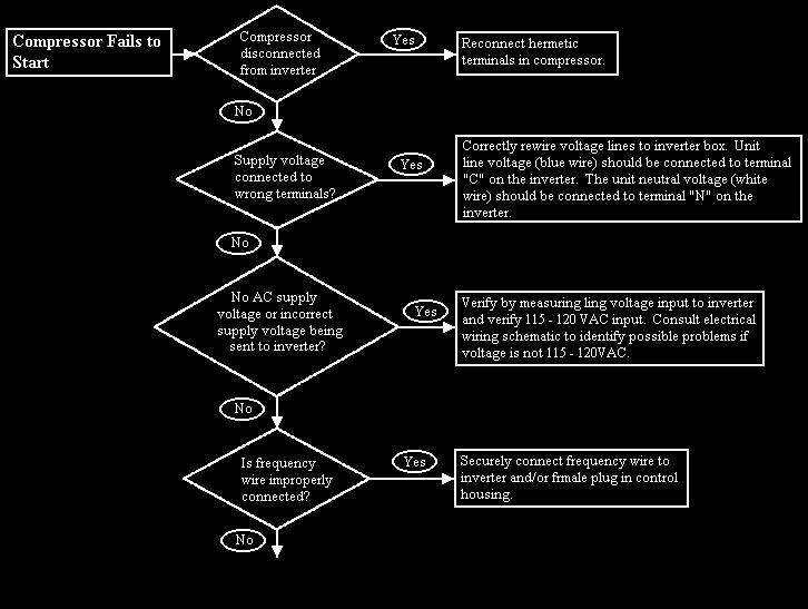
31 b) Maximum speed: if the speed signal requires operation above the speed limit than the compressor will be kept running at the maximum speed. h) SHORT CIRCUIT PROTECTON In case short circuits, a current detection circuit will open the power switches (cutting the current) and avoiding further damage to power devices or compressor winding. In case of a major failure in the hardware (short circuit of two or more power switches, a fuse will brake the current supplied to the inverter). ADAPTER BOARD LOGIC FLOWCHART 32
32 CONTROL BOARD OPERATION 33
33 TROUBLESHOOTING 34
34 TROUBLESHOOTING (con t) 35
35 ICE MAKER Specifications Mold heater: 185 watts, 264 ohms Thermostat: Close 17 ± 3 F (-8 ± 1 C) (Bimetal) Opens 32 ± 3 F (0 ± 1 C) Water fill: Motor cycle Testing Procedures 140 cc, 7.5 sec. Stamped in circuit. Plug in connectors One revolution of blades takes 3 minutes plug stall time on ice (eject and water fill) Operation Thermostat closes when temperature reaches 17 ± 3 F (-8.3 ± 1.5 C). Current flows through thermostat to motor. See Ice Maker Wiring Diagram. Motor is linked with drive gear. From module, there are copper contacts that ride on copper strips on backside of drive gear. As the drive gear rotates, contacts will make or break a circuit (tract) to the copper strips to operate ice maker. All components can be tested without removing ice maker or moving refrigerator away from installation. Remove cover. Test points are identified on module: N = Neutral side of line M = Motor connection H = Heater connection T = Thermostat connection L = L1 side of line V = Water valve connection Verify ice maker has power, shut off arm is down, and freezer is cold enough to close bimetal thermostat. Test point L and N will verify 120 volts to ice maker module. Test point T and H will verify bimetal thermostat is open or closed. Verify test probes go into test points ½ inch (1.25 cm). 1. Short T and H with a shunt (insulated 14 gauge wire with ends stripped back 5/8 inch (1.6 cm) to run motor. If motor runs. Replace bimetal thermostat. If motor does not run, replace module. 2. Leave jumper in for half of revolution. Touch heater mold. If heater mold feels warm, heater is working properly 3. Remove jumper. Water valve will be energized in last half of revolution if mold heater has not failed. 36
36 Ice Maker Module Ohmmeter Check No power to Ice Maker and Ejector Blades in End of Cycle Position Module, Motor, and Support Assembly Test Points Component Module Position Ohms L-H Mold & Heater Attached to Support 264 L-M Motor Separated form Heater 16,100 Module Voltage Checks with Meter or Test Light Power to Ice Maker Test Points Component Line Voltage 0 Volts L-N Module Power On Power Off T-H Bimetal Open Closed L-H Heater On Off L-M Motor On Off N-V Water Valve On Off DISASSEMBLY PROCEDURES Cover 1. Pull water adjustment knob forward. 2. Snap off cover. WARNING: To avoid electrical shock which can cause severe personal injury or death, disconnect power to refrigerator using power switch before servicing. Wires removed during disassembly must be replaced on proper terminals to insure correct earthing and polarization. After servicing, reconnect power using power switch. 1. Loosen both screws in module access ports. 2. Disconnect shut-off arm. 3. Pull mold from support assembly. Remove module only be removing 3 screws and pulling module out of housing. Shut-Off Arm 1. Pull shut-off arm out from white bushing. 2. Replace by pushing completely in. 3. Follow steps below. Module and Heater Assembly 1. Remove module and support assembly. 2. Install module and support assembly on replacement mold and heater assembly. Fill Cup 1. Remove module and support assembly. 2. Remove ejector blades and shut-off arm. 3. Pull fill cup from mold. 37


37 Ice Maker Ejector Blades or Stripper 1. Remove module and support assembly. 2. Install ejector blades, realigning D coupling with module cam. Accessing Control Box 1. Remove motor and contact assembly from control box be removing 3 screws. 2. Remove shut-off arm. 3. Pull free. Switches will jam if turned counterclockwise and gears will be destroyed if turned clockwise. Advance ice maker into cycle be using a jumper to bridge H to R. Ice maker will not run if motor is defective. Shut-off arm must be in on position. There are several slotted shafts on motor assembly board. Do not insert screwdriver and attempt to turn shafts. Slots permit assembly only. There are non-repairable and non-replaceable components in module. When diagnosing or repairing ice maker, do not remove module unless replacing module. Water Fill Valve Turning water level adjustment screw will move contact in relationship with contact ring segment. This causes contact to vary time water valve is energized. Contact ring is tapered at end of fill time. Turning screw clockwise decreases fill time. Turning screw counterclockwise increases fill time. ½ turn equals 20 cc or 1.2 seconds. Full turn equals 40 cc or 2.4 seconds. 38

.")
38 Ice Maker If water valve adjustment screw fall out, put screw in hole and align as shown below. 1 C). Ice will freeze when these temperatures are achieved. Cycling time will be slower if freezer temperature is not cold enough to achieve mode temperatures easily. Thermostat, mold heater, and wiring harness are replaceable. Any other failure, including motor, requires replacement of module assembly. Replacement mold assembly comes with new mold heater installed. Thermostat 1. Remove control box from mold by removing screws. When small hole is centered in large hole, water fill adjustment is 7.5 seconds (normal fill time). Water Problems Poor water quality can cause ice maker to fail or produce unacceptable cubes. Mineral content or sand can restrict screen in water fill valve or particle of sand can keep valve from seating properly. If water valve does not close, the following could occur no ice production small or hollow ice cubes flooding of ice container Install water filter to eliminate bad taste, odor, and visible contaminates. Mineral contact can cause lime build up in mold, Wicking of water over mold and poor cube release can occur. Silicone is applied at upper edges around fill cup and stripper. 2. Pull front of black housing free of mold. Thermostat is on mold side. 3. Grasp 1 thermostat clip and pull out. 4. Press in new thermostat. Verify pins are properly indexed. Electrical assembly does not need to be removed. If replacing module, transfer clips to new mold support. Use new thermal bonding material. Wiring Harness Remove wiring harness by pressing retaining tab and pulling forward. Temperature Problems Freezer temperatures above normal 0 ± 2 F (-18 ± 1 C) will slow down ice production. Increase ice production by setting freezer to colder setting. Thermostat cycling temperature (1 revolution ice maker) is 17 ± 3 F (-8 ± 39

39 Ice Maker Water Valve Water valve has 1 solenoid. Valve has 80 mesh screen water strainer. When solenoid is energized, the amount of water entering ice maker mold is directly proportional to length of time water valve switch is held closed by timing cam. Inside valve is a flow washer which acts as a water pressure regulator. Proper ice maker fill is 140cc ± 10cc at 7.5 seconds of water fill at an inlet pressure ranging from 20 to 120 PSI (1.4 to 8.2 bar). Wire Harness A non-resettable thermal fuse micro device 170 F (78 C) is spliced into black wire of ice maker wiring harness. Excessive heat can cause no ice production. Replacing wiring harness will only temporarily solve problem. Replace ice maker thermostats. 40
SERVICE NOTEBOOK BUILT-IN REFRIGERATOR VCSB481 / VCSB482
 SERVICE NOTEBOOK BUILT-IN REFRIGERATOR VCSB481 / VCSB482 VIKING RANGE CORPORATION, PO DRAWER 956, GREENWOOD, MS. 38930-USA TABLE OF CONTENTS Technical Information---------------------------------------------------------------------------
KAR-5 TECHNICAL EDUCATION KUWS246 WINE CELLAR JOB AID
 KAR-5 TECHNICAL EDUCATION KUWS246 WINE CELLAR I JOB AID 4317201 INTRODUCTION This Job Aid, KUWS246 WINE CELLAR, (Part No. 4317201), has been compiled to provide the most recent information on design, features,
AFI2538AE* AFI 2538AE*0, MFI2568AE* MFI2568AE*0 CAUTION
 Bottom Mount Refrigerator Technical Information AFI2538AE* AFI 2538AE*0, MFI2568AE* MFI2568AE*0! CAUTION Due to a possibility of personal injury or property damage, always contact an authorized technician
CAUTION. No-Load Performance, Controls in Normal Position
 Side-by-Side Refrigerator Technical Information JCD2292KT* JCD2292KT*2, JCD2295KE* JCD2295KE*2, JCD2297KE* JCD2297KE*2, JSD2695KES JSD2695KES2, JSD2695KG* JSD2695KG*0, JSD2697KE* JSD2697KE*2, MSD2660KEG*
Bottom Mount Refrigerator---Technical Information
 Bottom Mount Refrigerator---Technical Information WARNING Electrical Shock Hazard Disconnect power before servicing. Replace all parts and panels before operation. Failure to do so can result in death
Service. International Bottom Mount Refrigerators. Amana
 Service This manual is to be used by qualified appliance technicians only. Maytag does not assume any responsibility for property damage or personal injury for improper service procedures done by an unqualified
JBL2088HES JBL2088HES0, JBR2088HES JBR2088HES0, JFC2089HEP JFC2089HEP0, JFC2089HES JFC2089HES0, JFC2089HPF JFC2089HPF0, JFC2089HPY JFC2089HPY0
 Bottom Mount Refrigerator Technical Information JBL2088HES JBL2088HES0, JBR2088HES JBR2088HES0, JFC2089HEP JFC2089HEP0, JFC2089HES JFC2089HES0, JFC2089HPF JFC2089HPF0, JFC2089HPY JFC2089HPY0 Due to a possibility
WMHP Series R410a Heat Pump INSTALLATION INSTRUCTIONS
 WMHP Series R410a Heat Pump INSTALLATION INSTRUCTIONS **WARNING TO INSTALLER, SERVICE PERSONNEL AND OWNER** Altering the product or replacing parts with non authorized factory parts voids all warranty
Due to a possibility of personal injury or property damage, always contact an authorized technician for service or repair of this refrigerator.
 Bottom Mount Refrigerator Technical Information Due to a possibility of personal injury or property damage, always contact an authorized technician for service or repair of this refrigerator.! CAUTION
Service. 18, 21, & 22 Cu. Ft. Bottom Mount Refrigerators
 Service 18, 21, & 22 Cu. Ft. Bottom Mount Refrigerators This Base Manual covers 18, 21, and 22 Cu. Ft. Bottom Mount Refrigerators. Refer to individual Technical Sheet for specific information on models.
Freightliner Refrigerator Troubleshooting Guide For (TJ18F) (TJ22F) (TJ18FP3)
 (TJ22F) (TJ18FP3)") www.dometic.com Freightliner Refrigerator Troubleshooting Guide For Before initiating troubleshooting, the following equipment is recommended: Multimeter, 20 gauge (min) wires to use as jumpers, and 12Vdc
www.dometic.com Freightliner Refrigerator Troubleshooting Guide For Before initiating troubleshooting, the following equipment is recommended: Multimeter, 20 gauge (min) wires to use as jumpers, and 12Vdc
FOR SERVICE TECHNICIAN S USE ONLY
 F SERVICE TECHNICIAN S USE ONLY NOTE: This sheet contains important Technical Service Data. Tech Sheet Do Not Remove Or Destroy DANGER Electrical Shock Hazard Only authorized technicians should perform
CAUTION. No-Load Performance, Controls in Normal Position. Percent Run Time ±10%
 Bottom Mount Refrigerator Technical Information JBC2088HT* JBC2088HT*1, JBL2088HES JBL2088HES1, JBR2088HES JBR2088HES1, JFC2089HE* JFC2089HE*1, JFC2089HP* JFC2089HP*1, JFC2089HT* JFC2089HT*1, KBFA20ERBL
NO. 15FD-742 ISSUED: AUG. 10, 2007 REVISED: SEP. 30, 2013 HOSHIZAKI SELF-CONTAINED CRESCENT CUBER KM-30A KM-35A KM-50A KM-75A MODEL SERVICE MANUAL
 NO. 15FD-742 ISSUED: AUG. 10, 2007 REVISED: SEP. 30, 2013 HOSHIZAKI SELF-CONTAINED CRESCENT CUBER MODEL KM-30A KM-35A KM-50A KM-75A SERVICE MANUAL CONTENTS PAGE I. SPECIFICATIONS--------------------------------------------------------------------------------------1
Refrigerant Recovery Machine. Model No Operating Manual
 Refrigerant Recovery Machine Model No. 25700 Operating Manual Safety Precautions WARNING : TO PREVENT PERSONAL INJURY AND / OR EQUIPMENT DAMAGE, CAUTION - Risk of injury. This equipment should only be
R100 Oil-Less Refrigerant Recovery Unit
 R100 Oil-Less Refrigerant Recovery Unit Operation Manual 1 INTRODUCTION Welcome to simple, efficient refrigerant recovery with your new YELLOW JACKET Refrigerant Recovery Unit, R100. This unit combines
GENERAL 2004 HVAC SYSTEMS. Manual HVAC System - Sorento SPECIFICATIONS. Fig. 1: Air Conditioner Specifications Courtesy of KIA MOTORS AMERICA, INC.
 Fig. 2: Blower & Evaporator Unit Specifications 2004 HVAC SYSTEMS Manual HVAC System - Sorento GENERAL SPECIFICATIONS AIR CONDITIONER Fig. 1: Air Conditioner Specifications BLOWER AND EVAPORATOR UNIT HEATER
FOR SERVICE TECHNICIAN S USE ONLY
 FOR SERVICE TECHNICIAN S USE ONLY NOTE: This sheet contains important Technical Service Data. Tech Sheet Do Not Remove Or Destroy DANGER Electrical Shock Hazard Only authorized technicians should perform
Service. 15 Cubic Foot Top Mount Refrigerators. Amana ATB1504ARQ ATB1504ARW. Maytag MTB1502ARQ MTB1502ARW MTB1504ARQ MTB1504ARW
 Service This manual is to be used by qualified appliance technicians only. Maytag does not assume any responsibility for property damage or personal injury for improper service procedures done by an unqualified
NO. F ISSUED: JUN. 15, 2009 REVISED: HOSHIZAKI MODULAR CRESCENT CUBER KMD-201AA KMD-201AWA MODEL SERVICE MANUAL
 NO. F037-775 ISSUED: JUN. 15, 2009 REVISED: HOSHIZAKI MODULAR CRESCENT CUBER MODEL KMD-201AA KMD-201AWA SERVICE MANUAL CONTENTS PAGE I. SPECIFICATIONS ---------------------------------------------------------------------------------------
CAUTION. All safety information must be followed as provided in Service Manual RS ! WARNING
 Amana Technical Information³Refrigerator P1303511W Due to a possibility of personal injury or property damage, always contact an authorized technician for servicing or repair of this refrigerator. Refer
! WARNING CAUTION DANGER WARNING CAUTION
 CAUTION DANGER CAUTION ESU F 15 J W A U F 7 0 K W Series H J Storage Capacity 12 Cubic Foot 15 Cubic Foot 17 Cubic Foot 20 Cubic Foot Defrost Type Blank Manual F Free-O-Frost Color W White Product ESU
14. The center port of the manifold is used for evacuation, charging and refrigerant recovery.
 HET- 190 ESL Support page 1 CORE Basic Refrigeration Circuit 1. Liquid refrigerant boils in the evaporator. Heat is absorbed. The heat energy absorbed converts refrigerant liquid into vapor. 2. Refrigerant
OPERATION & MAINTENANCE MANUAL TX600
 OPERATION & MAINTENANCE MANUAL TX600 RTI TECHNOLOGIES, INC. 4075 East Market Street York, PA 17402 Manual P/N 035-80118-00 (Rev B) ! TABLE OF CONTENTS! TX600 Before Using Page 2 Safety Precautions Page
Some of these procedures need to be performed to conform to requirements of the Clean Air Act.
 Leak Detection, Recovery, Evacuation and Charging Four basic service procedures used to repair and maintain a mechanical refrigeration system are leak detection, evacuation, recovery, and refrigerant charging.
Refrigerant Recovery Unit, Model RRU134
 Installation, Operation & Maintenance Manual IOMM RRU134 Group: Refrigerant Effective: December 2000 Supersedes: New Refrigerant Recovery Unit, Model RRU134 1999 McQuay International Table of Contents
MR3CCUHV Temperature/Defrost Control
 Master Catalog 125 Temperature Controls Section A Product/Technical Bulletin Issue Date 0401 MR3CCUHV Temperature/Defrost Control The MR3CCUHV Temperature/Defrost Control is designed to control the temperature
HOSHIZAKI MODULAR CRESCENT CUBER MODEL KM-280MAH KM-280MWH SERVICE MANUAL
 NO. 73117 ISSUED: AUG. 15, 2004 REVISED: HOSHIZAKI MODULAR CRESCENT CUBER MODEL KM-280MAH KM-280MWH SERVICE MANUAL IMPORTANT Only qualified service technicians should attempt to service or maintain this
Side-by-side combined refrigerator-freezer
 REPAIR INSTTRUCTTI I IONS Side-by-side combined refrigerator-freezer 1 SAFETY... 2 4.1 Electronic controller... 8 1.1 Safety instructions... 2 1.2 Repair instructions... 2 2 INSTALLATION... 3 3 OPERATION...
Air Conditioning Operation and Troubleshooting Matt Dunham
 Air Conditioning Operation and Troubleshooting Matt Dunham Major Components (10 Minutes) Compressor heart of the system, causes refrigerant to flow by increasing the pressure of the refrigerant Metering
Service Manual Moffat
 Service Manual Moffat ELECTRONIC POLAR WITH EXTERIOR DISPLAY PUB # 06-MAN/RE-01 MTR12YATWW December, 2006 1 CONTENTS SECURITY DISPLAY FEATURES TEMPERATURE SELECTION QUICK COOLING VACATION LOCK CONTROL
FOR SERVICE TECHNICIAN S USE ONLY
 F SERVICE TECHICIA S USE OY TE: This sheet contains important Technical Service Data. Tech Sheet Do ot Remove Or Destroy DAGER Electrical Shock Hazard Only authorized technicians should perform diagnostic
Service Manual For model N260 - a 2.4 cu. ft., 2-way refrigerator. For model N a 2.4 cu. ft., 3-way refrigerator.
 Service Manual For model N260 - a 2.4 cu. ft., 2-way refrigerator. For model N260.3 - a 2.4 cu. ft., 3-way refrigerator. NORCOLD, Inc. P.O. Box 4248 Sidney, OH 45365-4248 Part No. 619260A (4-98) Table
HNC-120BE-L/R-B HNC-150BE-L/R-B HNC-180BE-L/R-B HNC-210BE-L/R-B COUNTER SHOWCASE MODEL SERVICE MANUAL HOSHIZAKI
 NO. S051-800 ISSUED: MAR. 26, 2010 REVISED: HOSHIZAKI COUNTER SHOWCASE MODEL HNC-120BE-L/R-B HNC-150BE-L/R-B HNC-180BE-L/R-B HNC-210BE-L/R-B SERVICE MANUAL IMPORTANT This manual should be read carefully
Condensing Unit Installation and Operating Instructions
 Bulletin WCU_O&I 01 June 2003 Condensing Unit Installation and Operating Instructions WCU Air Cooled Condensing Unit Table of Contents Section 1. Section 2. Section 3. Section 4. Section 5. Section 6.
Part 3 Troubleshooting
 Part Troubleshooting What is in this part? This part contains the following chapters: Chapter See page Troubleshooting 2 Error Codes: Hydro-box 7 Error Codes: Outdoor Units Error Codes: System Malfunctions
Portable Refrigerator
 Portable Refrigerator Owners Manual Single door 40 litre 65 litre 80 litre 125 litre Double door 74 litre 95 litre 2009 Introduction The National Luna range of portable fridges and freezers are high-performance,
Operator: Save these instructions for future use!
 50A66-743 Integrated Furnace Control Operator: Save these instructions for future use! FAILURE TO READ AND FOLLOW ALL INSTRUCTIONS CAREFULLY BEFORE INSTALLING OR OPERATING THIS CONTROL COULD CAUSE PERSONAL
OPERATION & MAINTENANCE MANUAL AC860
 OPERATION & MAINTENANCE MANUAL AC860 Refrigerant Handling System Manual P/N 035-80913-00 TABLE OF CONTENTS Startup & Safe Operation... 1 Introduction to the AC860... 2 Control Panel... 3 Keypad Functions...
KitchenAid Food Stream Solutions Classic and Integrated Series
 KitchenAid Food Stream Solutions Classic and Integrated Series KitchenAid Chapter list Installation Range overview Installation General Information Function Compressor Power Control Board Defrosting Heating
Room Air Conditioner Service and Parts Manual
 Cool Dry Temp Mode Room Air Conditioner Service and Parts Manual F Fan Speed hr Timer 0n 0ff Money Saver Fan Only Auto Swing Power CP06 CP08 93011401_01 CONTENTS 1. PREFACE 1.1 SAFETY PRECAUTIONS...2 1.2
Interrupted Ignition Series Oil Primary Control
 Interrupted Ignition Series Oil Primary Control Application Guide & Installation Instruction for ICM1511*, ICM1512*, ICM151*, ICM1514* For more information on our complete range of American-made products
INSTRUCTION MANUAL 4-WAY BALL VALVE Digital Manifold
 LOW VAC INSTRUCTION MANUAL 4-WAY BALL VALVE Digital Manifold REF HIGH SPECIAL FEATURES Low battery indicator Displays 63 refrigerants Displays corresponding saturation, dew or bubble point temperature
Norcold Repair Guide for Ice Maker
 Norcold Repair Guide for Ice Maker Section 10 Table of Contents Page: 10-2 General Description 10-2 Refrigerator Specifications 10-2 Refrigerator Operating Limits 10-2 Refrigerator Current Draws 10-2 Ice
KITS COMMON TO HEATING AND COOLING EQUIPMENT 504,652M 03/04. Supersedes 503,249M
 2004 Lennox Industries Inc. Dallas, Texas KITS COMMON TO HEATING AND COOLING EQUIPMENT 504,652M 03/04 Supersedes 503,249M Litho U.S.A. COMPRESSOR REPLACEMENT KIT INSTALLATION INSTRUCTIONS FOR COMPRESSOR
NUMBER: ISSUED: JULY 13, /336 73/23 STACKABLE CRESCENT CUBER KM-1300SWH-E SERVICE MANUAL FOR QUALIFIED SERVICE PERSON HOSHIZAKI
 89/336 73/23 NUMBER: 73141 ISSUED: JULY 13, 2006 STACKABLE CRESCENT CUBER KM-1300SWH-E SERVICE MANUAL FOR QUALIFIED SERVICE PERSON HOSHIZAKI IMPORTANT Only qualified service technicians should attempt
SERVICE MANUAL FOR MODEL RM-10
 SERVICE MANUAL FOR MODEL RM-10 REQUIRED TOOLS CORDLESS DRILL COPPER CUTTING TUBE 1/2 OPEN WRENCH SOLDERING IRON SCREWDRIVER SET WITH 9/32 SOCKET VISE GRIP PIERCING VALVE PRECISION FLAT BLADE SLOTTED SCREWDRIVER
Hoshizaki America, Inc.
 Hoshizaki America, Inc. Commercial Refrigerators & Freezers Models RR28A RR55A RF28A RF55A A Superior Degree of Reliability SERVICE MANUAL www.hoshizaki.com Number: 73139 Issued: 8-31-2006 IMPORTANT Only
OPERATION & MAINTENANCE MANUAL RHS680
 OPERATION & MAINTENANCE MANUAL RHS680 Refrigerant Handling System 4075 East Market Street York, PA 17402 800-468-2321 tech@rtitech.com Manual P/N 035-80740-00 (Rev 1- May 22, 2001) TABLE OF CONTENTS Startup
KSGD-01W/S SEMI CONDUCTOR STAND ALONE REFRIGERANT LEAK DETECTOR. Instructions for :- KSGD-01W/S Semi Conductor Standalone Refrigerant Leak Detector
 Issue 1 KSGD-01W/S SEMI CONDUCTOR STAND ALONE REFRIGERANT LEAK DETECTOR Installation Manual Instructions for :- For safe and correct use please read the installation manuals supplied with the equipment.
Scotsman Technical Training. CU50 Cube Ice Machine
 Scotsman Technical Training CU50 Cube Ice Machine Major Topics Overview Installation Start Up Sequence of Operation Maintenance Diagnostics Service Procedures Models Two Base Models Gravity Drain Pump
OWNER S MANUAL Manufactured Home Downflow Gas Furnace: MGD-B Series
 OWNER S MANUAL Manufactured Home Downflow Gas Furnace: MGD-B Series Heat Controller, Inc. 1900 Wellworth Ave. Jackson, MI 49203 (517)787-2100 www.heatcontroller.com Owner s Manual MGD-B SERIES GAS FURNACE
! WARNING To avoid risk of electrical shock, personal injury or death; disconnect power to range before servicing, unless testing requires power.
 Technical Information Electric Slide-In Range JES8850BC* JES9900BC* JES9860BC* Due to possibility of personal injury or property damage, always contact an authorized technician for servicing or repair
SERVICE MANUAL MUY-GL24NA - U1. No. OBH733. Models HFC. Revision B: REVISED EDITION-B R410A
 Revision B: MUZ-GL09NA- U8 and MUZ-GL09NAH- U8 have been added. Please void OBH733 REVISED EDITION-A. OUTDOOR INDOOR UNIT UNIT SERVICE MANUAL HFC utilized R410A. OBH733 REVISED EDITION-B Models MUZ-GL09NA
KM-900MAF KM-900MWF KM-900MRF KM-900MRF3
 NO.: ISSUED: REVISED: 73083 MAR. 19, 1999 DEC. 15, 2003 HOSHIZAKI MODULAR CRESCENT CUBER MODELS KM-900MAF KM-900MWF KM-900MRF KM-900MRF3 SERVICE MANUAL IMPORTANT Only qualified service technicians should
Dometic Manual Refrigerators
 This section addresses the most common system problems associated with supplied by The Dometic Corporation. Our intent is to provide you with a guideline of checks to make, should you encounter one of
Service Manual Inch Undercounter Refrigeration
 Service Manual This manual is to be used by qualified appliance technicians only. Viking does not assume any responsibility for property damage or personal injury for improper service procedures done by
Pro-Set TRA21 SERIES Mobile Multiple Refrigerant Recovery / Recycle System
 Pro-Set TRA21 SERIES Mobile Multiple Refrigerant Recovery / Recycle System Certified by ITS to meet SAE J2810 for R-134a Designed to meet new SAE J2851 for R-1234yf MANUAL GENERAL INFORMATION Table of
Hoshizaki America, Inc.
 Hoshizaki America, Inc. Commercial Refrigerators & Freezers Models SafeTemp A Superior Degree of Reliability SERVICE MANUAL www.hoshizaki.com Number: 73096 Issued: 10-9-2000 Revised: 3-7-2007 IMPORTANT
Due to a possibility of personal injury or property damage, always contact an authorized technician for service or repair of this refrigerator.
 Bottom Mount Technical Information Due to a possibility of personal injury or property damage, always contact an authorized technician for service or repair of this refrigerator.! CAUTIN All safety information
V-220 / V-320 Heater Kits Installation Instructions TK IM (Rev. 0, 06/17)
") Installation Manual V-220 / V-320 Heater Kits Installation Instructions TK 56340-18-IM (Rev. 0, 06/17) Installation Manual V-220 / V-320 Heater Kits Installation Instructions TK 56340-18-IM (Rev. 0, 06/17)
Installation Manual V-220 / V-320 Heater Kits Installation Instructions TK 56340-18-IM (Rev. 0, 06/17) Installation Manual V-220 / V-320 Heater Kits Installation Instructions TK 56340-18-IM (Rev. 0, 06/17)
1998 Expedition/Navigator Workshop Manual
 Page 1 of 8 SECTION 412-00: Climate Control System - General Information 1998 Expedition/Navigator Workshop Manual DESCRIPTION AND OPERATION Procedure revision date: 02/11/2000 Climate Control System WARNING:
KML F SERIES KML H SERIES
 NO.: ISSUED: REVISED: 73085 AUG. 18, 1999 JAN. 13, 2004 HOSHIZAKI MODULAR CRESCENT CUBER MODELS KML F SERIES KML H SERIES SERVICE MANUAL IMPORTANT Only qualified service technicians should attempt to service
Owner s Manual. Model AC375C Refrigerant Recovery, Recycle, and Recharge Unit
 Owner s Manual Model AC375C Refrigerant Recovery, Recycle, and Recharge Unit Model AC375C Recover, Recycle, and Recharge Unit for R-12 or R-134a Refrigerant Voltage: 220 230; 50 60 Hz SAFETY DEFINITIONS:
Caresaver Universal Refrigerant Recovery Unit
 Operation Manual Caresaver Universal Refrigerant Recovery Unit 2 CONTENTS CHAPTER 1 INTRODUCTION AND OVERVIEW Specifications 3 Health and Safety 4-5 Component Location and Identification 6-9 CHAPTER 2
Climate Control System
 Page 1 of 13 SECTION 412-00: Climate Control System General Information DESCRIPTION AND OPERATION 1998 Mark VIII Workshop Manual Climate Control System Cautions and Warnings WARNING: To avoid accidental
SWIMMING POOL & SPA HEAT PUMPS OWNERS OPERATIONAL MANUAL
 SWIMMING POOL & SPA HEAT PUMPS OWNERS OPERATIONAL MANUAL MODEL AT105 AT115 AT130 with Titanium Heat Exchanger 2213 Andrea Lane Ft. Myers FL 33912 888-297-3826 941-482-0606 www.aquathermheatpumps.com DIGITAL
SERVICE MANUAL OUTDOOR UNIT MUZ-FH06NAH MUZ-FH09NAH MUZ-FH06NA MUZ-FH09NA MUZ-FH09NA - 1 MUZ-FH09NAH - 1 MUZ-FH12NA MUZ-FH12NAH
 Revision D: Capacity corrections have been corrected [7-1. 2), 3)]. OBH684 REVISED EDITION-C is void. OUTDOOR UNIT SERVICE MANUAL HFC utilized R410A. OBH684 REVISED EDITION-D Models MUZ-FH06NA MUZ-FH09NA
SERVICE MANUAL MUZ-DM25VA - E1, ER1, ET1 MUZ-DM35VA - E1, ER1, ET1 OUTDOOR UNIT. No. OBH751. Models HFC R410A
 OUTDOOR UNIT SERVICE MANUAL HFC utilized R410A. Models MUZ-DM25VA - E1, ER1, ET1 MUZ-DM35VA - E1, ER1, ET1 Indoor unit service manual MSZ-DM VA Series (OBH750) CONTENTS 1. TECHNICAL CHANGES 2 2. PART NAMES
50M Integrated Single or Two-Stage HSI Integrated Furnace Control Kit INSTALLATION INSTRUCTIONS
 50M56-743 Integrated Single or Two-Stage HSI Integrated Furnace Control Kit INSTALLATION INSTRUCTIONS FAILURE TO READ AND FOLLOW ALL INSTRUCTIONS CAREFULLY BEFORE INSTALLING OR OPERATING THIS CONTROL COULD
User s Manual. TIGER S EYE E-Series Mark V Jockey. TIGERFLOW Systems, Inc Mint Way Dallas, Texas
 User s Manual TIGER S EYE E-Series Mark V Jockey TIGERFLOW Systems, Inc. 4034 Mint Way Dallas, Texas 75237 214-337-8780 www.tigerflow.com TABLE OF CONTENTS Introduction... 4 Sequence of Operation... 5
21D83M-843 Integrated Single Stage Furnace Control Replacement Kit INSTALLATION INSTRUCTIONS
 21D83M-843 Integrated Single Stage Furnace Control Replacement Kit INSTALLATION INSTRUCTIONS FAILURE TO READ AND FOLLOW ALL INSTRUCTIONS CAREFULLY BEFORE INSTALLING OR OPERATING THIS CONTROL COULD CAUSE
! WARNING To avoid risk of electrical shock, personal injury or death; disconnect power to range before servicing, unless testing requires power.
 Technical Information Electric Slide-In Range JES9750BA* JES9860BA* Due to possibility of personal injury or property damage, always contact an authorized technician for servicing or repair of this unit.
SERVICE MANUAL. No. OBH747 REVISED EDITION-A. Models HFC
 Revision A: MUZ-HM09/12NA- U8, MUZ-HM09/12NA2- U8, MUZ-HM15/18NA- U1, MUZ-HM15/18NA2- U1 and MUZ-HM24NA2- U1 have been added. Please void OBH747. OUTDOOR INDOOR UNIT UNIT SERVICE MANUAL HFC utilized R410A.
REFRIGERANT SYSTEM SERVICE WARNINGS
 2005 HVAC Refrigerant System - MX-5 Miata REFRIGERANT SYSTEM SERVICE WARNINGS USING/HANDLING UNAPPROVED REFRIGERANT Using a flammable refrigerant, such as OZ-12, in this vehicle is dangerous. In an accident,
50A Integrated Furnace Control
 50A56-956 Integrated Furnace Control INSTALLATION INSTRUCTIONS FAILURE TO READ AND FOLLOW ALL INSTRUCTIONS CAREFULLY BEFORE INSTALLING OR OPERATING THIS CONTROL COULD CAUSE PERSONAL INJURY AND/OR PROPERTY
SERVICE MANUAL REFRIGERATION
 SERVICE MANUAL REFRIGERATION ELECTROLUX HOME PRODUCTS S.p.A. Publication no. Spares Operations Italy 599 37 75-07 Corso Lino Zanussi, 30 060824 I - 33080 PORCIA / PN (ITALY) ITZ/SERVICE/AA Fax +39 0434
Table of Contents. Service Procedures. Service Procedures. Measuring Superheat (4) Measuring Subcooling (5) Airflow Calculation (6-8)
 Measuring Subcooling (5) Airflow Calculation (6-8)") Table of Contents Refrigeration Cycle Service Procedures Measuring Superheat (4) Measuring Subcooling (5) Airflow Calculation (6-8) Solving Problems Identifying Low System Charge (9-11) Identifying High
Table of Contents Refrigeration Cycle Service Procedures Measuring Superheat (4) Measuring Subcooling (5) Airflow Calculation (6-8) Solving Problems Identifying Low System Charge (9-11) Identifying High
Isco 3700ZR Sampler. Manual Set
 Isco 3700ZR Sampler Manual Set Assembly #60-2744-045 Copyright 2001. All rights reserved, Teledyne Isco Revision D, December 14, 2012 This set of manuals supports the Isco 3700ZR Refrigerated Sampler.
SERVICE MANUAL FOR QUALIFIED SERVICE PERSON HOSHIZAKI 89/336 73/23 SELF-CONTAINED CRESCENT CUBER KM-150BAF-E KM-150BWF-E
 89/336 73/23 NUMBER: 73108 ISSUED: APRIL 19, 2000 REVISED: JAN. 13, 2004 SELF-CONTAINED CRESCENT CUBER KM-150BAF-E KM-150BWF-E SERVICE MANUAL FOR QUALIFIED SERVICE PERSON HOSHIZAKI IMPORTANT Only qualified
2008 DOUBLE DRAWER UNDER COUNTER REFRIGERATOR / FREEZER PRODUCTS
 TECHNICAL EDUCATION R-107 2008 DOUBLE DRAWER UNDER COUNTER REFRIGERATOR / FREEZER PRODUCTS KDDC24RVS KDDO24RVX KDDC24CVS KDDO24CVX KDDC24FVS KDDO24FVX JUD248RCRS JUD248RCCX JUD248CCRS JUD248CCCR JUD248FCRS
Fast Track Troubleshooting
 Fast Track Troubleshooting Models Covered: RF266AD**/XAA French Door Refrigeration IMPORTANT SAFETY NOTICE For Technicians Only This service data sheet is intended for use by persons having electrical,
SEA FROST BD 12 OR 24-VOLT D.C. AIR-COOLED SYSTEM
 148 OLD CONCORD TURNPIKE BARRINGTON, NH 03825 USA TEL (603) 868-5720 FAX (603) 868-1040 1-800-435-6708 E-Mail:sales@seafrost.com www.seafrost.com SEA FROST BD 12 OR 24-VOLT D.C. AIR-COOLED SYSTEM CONDENSING
USER MANUAL MINITRACER PORTABLE SNIFFER
 USER MANUAL MINITRACER PORTABLE SNIFFER CONTACT US PHONE/FAX Phone: 801.486.1015 Fax: 801.486.1032 ADDRESS FLUIDX Equipment, Inc. 139 W. 2260 S. Salt Lake City, UT 84115 www.fluidxinc.com SMT-07-1006 Rev
Product Manual SZ1144
 Product Manual SZ1144 Refrigeration Temperature Monitor Communicating Controls Description The SZ1144 is a microprocessor-based monitoring and alarm interface designed to monitor up to four 1000 Ω platinum
INSTALLATION INSTRUCTIONS and OPERATING MANUAL. *Aquastat is a registered trademark of Honeywell International, Inc.
 MODEL 3200-Plus Temp Limit / LWCO Control with Thermal Targeting for Water Boilers 120 VAC Input / 24 VAC Burner Circuit PATENT. 7,891,572 INSTALLATION INSTRUCTIONS and OPERATING MANUAL Saves Fuel Features
CS/CD/CP AIR COOLED CONDENSING UNITS (P/N E207120C R2)
") CS*/CD*/CP* Series Air Cooled Condensing Units Operating and Installation Manual CS/CD/CP AIR COOLED CONDENSING UNITS (P/N E207120C R2) TABLE OF CONTENTS I. Receipt of Equipment 2 II. Piping...4 III. System
CS*/CD*/CP* Series Air Cooled Condensing Units Operating and Installation Manual CS/CD/CP AIR COOLED CONDENSING UNITS (P/N E207120C R2) TABLE OF CONTENTS I. Receipt of Equipment 2 II. Piping...4 III. System
P4200PM / P5000PM Remote Air Dryer User s Guide
 P4200PM / P5000PM Remote Air Dryer User s Guide 1. Welcome & Congratulations Congratulations on your purchase of a new PUREGAS P4200PM / P5000PM Air Dryer! We here at PUREGAS are very proud of our products
Automatic Ice maker. Service manual MIM250
 Automatic Ice maker Service manual MIM250 1 Table of contents Installation Guidelines ---------------------------------------------------------3 How the Ice Maker Works ----------------------------------------------------4
B-40/B-41 Modulating Temperature Controller
 INSTALLATION & OPERATING INSTRUCTIONS B-40/B-41 Modulating Temperature Controller For Raytherm Boilers & Water Heaters H2 514-4001 WH2 2100-4001 Catalog No. 5000.70 Effective: 12-21-11 Replaces: NEW P/N
TECHNICAL SERVICE GUIDE
 GE Consumer Home Services Training TECHNICAL SERVICE GUIDE Electronic Icemaker Pub # 31-9063 8/00 ! IMPORTANT SAFETY NOTICE The information in this service guide is intended for use by individuals possessing
KM-630MAF KM-630MWF KM-630MRF
 NO.: 73082 ISSUED: MAR. 19, 1999 REVISED: DEC. 15, 2003 HOSHIZAKI MODULAR CRESCENT CUBER MODEL KM-630MAF KM-630MWF KM-630MRF SERVICE MANUAL IMPORTANT Only qualified service technicians should attempt to
RANGER 8600 DOWNLOADABLE CONTROL COMMUNICATOR INSTALLATION MANUAL
 RANGER 8600 DOWNLOADABLE CONTROL COMMUNICATOR INSTALLATION MANUAL TABLE OF CONTENTS GENERAL DESCRIPTION... 2 STANDARD AND OPTIONAL PARTS LIST... 2 PARTS DIAGRAM... 3 TERMINAL DRAWING AND SPECIAL NOTES...
Northwest RV Supply Manual Compliments of Printed From 900 & 9100 Series
 900 & 9100 Series Service Manual & Parts List for Models 9182 9183 9162 9163 982 983 962 963 Safety Information............... 1 Introduction................... 2 Specifications.................. 3 Operating
Operator: Save these instructions for future use!
 WHITE-RODGERS 50A55-474 & 50A55-571 Integrated Furnace Controls INSTALLATION INSTRUCTIONS Operator: Save these instructions for future use! FAILURE TO READ AND FOLLOW ALL INSTRUCTIONS CAREFULLY BEFORE
SERIES VAC Microprocessor-Based Direct Spark Ignition Control FEATURES APPLICATIONS SPECIFICATIONS DESCRIPTION. Export Information (USA)
") R SERIES 35-70 120 VAC Microprocessor-Based Direct Spark Ignition Control F-35-70 November 2015 FEATURES Safe start with DETECT-A-FLAME flame sensing technology Custom pre-purge and inter-purge timings
R SERIES 35-70 120 VAC Microprocessor-Based Direct Spark Ignition Control F-35-70 November 2015 FEATURES Safe start with DETECT-A-FLAME flame sensing technology Custom pre-purge and inter-purge timings
DC200 Digital Dispenser Operating Manual
 DC200 Digital Dispenser Operating Manual 2015 Fisnar Phone: (973) 646-5044 E-mail: info@fisnar.com Table of Contents Product Safety Statements 4 Specifications 6 Accessories 6 External Controls 7 Machine
SECTION 2 SAFETY, TOOLS & EQUIPMENT, SHOP PRACTICES UNIT 8 SYSTEM EVACUATION
 SECTION 2 SAFETY, TOOLS & EQUIPMENT, SHOP PRACTICES UNIT 8 SYSTEM EVACUATION UNIT OBJECTIVES After studying this unit, the reader should be able to Describe a standing pressure test. Choose a leak detector
AE R1 October to 5 Ton ZPS*K6 Copeland Scroll Two-Stage Compressors
 October 2017 1.5 to 5 Ton ZPS*K6 Copeland Scroll Two-Stage Compressors Safety Safety Instructions... 2 Safety Icon Explanation... 2 Instructions Pertaining to Risk of Electrical Shock, Fire, or Injury
Product Information and Technical Guide
 Product Information and Technical Guide Side by Side and Top Mount Refrigerators July 2003 - December 2003 White-Westinghouse 5995540384 January 2004 TABLE OF CONTENTS Safe Servicing Practices ------------------------------------------------------------------------------------------