Installation, Operation & Maintenance Manual
|
|
|
- Domenic Goodman
- 5 years ago
- Views:
Transcription

1 Installation, Operation & Maintenance Manual Direct Expansion, Dual Circuit DX 21 to 106 kw Air and Water/Glycol Cooled Data Aire, Inc. 230 W. Blueridge Ave. Orange, CA
2 CONGRATULATIONS ON THE SELECTION OF A DATA AIRE PRECISION ENVIRONMENTAL CONTROL SYSTEM. PROPER INSTALLATION, OPERATION AND MAINTENANCE OF THIS EQUIPMENT WILL ENSURE YEARS OF OPTIMAL PERFORMANCE. There are separate User Manuals for other components of your Data Aire precision environmental cooling system including dap4, condenser/condensing unit and fluid cooler. NOTE: This manual is intended to assist trained service personnel by providing necessary guidelines for this particular equipment. Service to Data Aire units should be done by qualified individuals with an adequate background in areas such as HVAC, electrical, plumbing and electronics, as applicable. WARNING: Service performed by unauthorized or unqualified technicians may void manufacturers warranties and could result in property damage and/ or personal injury. Special care should be given to those areas where these symbols appear. Data Aire, Inc. reserves the right to make design changes for the purpose of product improvement or to withdraw any design without notice.
3 Table of Contents 1 INTRODUCTION Product Information Model Identification Inspection Paperwork INSTALLATION Installation Checklist Room Considerations Equipment Handling Rigging Locating the Unit Downflow Units Upflow Units Storage Piping Air Cooled Unit Piping Discharge Lines Liquid Lines Suction Lines Connection Sizes, Air Cooled Units Field Piping, Remote Condenser Field Piping, Remote Condensing Unit Water/Glycol Cooled Unit Piping Field Piping, Water/Glycol System Connection Sizes, Water/Glycol Cooled Units Connection Sizes, Fluid Coolers Auxiliary Chilled Water/Energy Saver Coil Piping Condensate Drain Piping Humidifier Piping Steam Generator Humidifier Dry Steam Humidifier Leak Testing ELECTRICAL CONNECTIONS Electrical Service Nameplate Ratings Grounding Voltage Tolerance Auxiliary Control Wiring for Remote Heat Exchangers Remote Shutdown Remote Alarm Contacts Condensate Pumps (Optional) Condensate Probe Water Sensing Cable (Optional) Remote Temperature and Humidity Sensors (Optional) Manual Override Switches Wiring Diagrams EEV Connection INSTALLATION OF REMOTE OUTDOOR HEAT EXCHANGER CHARGING...23
4 5.1 Voltage Phase Check Evaporator Power Phasing Remote Heat Exchanger Fan Motor Phasing Evacuation Air Cooled Systems Fan Speed Control System Charging Flooded System Charging Water/Glycol System Water/Glycol Cooled System Charging Refrigerant Handling Important Refrigeration Components Expansion Valves High Pressure Cutout Switch Low Pressure Cutout Switch Liquid Line Solenoid Valve (Optional) GLYCOL SYSTEMS Glycol Concentration Internal (Fluid) Volume Up and Downflow Evaporators Brazed-Plate Condensers Internal (Fluid) Volume Fluid Coolers Fluid Cooler Information CONTROLS dap4 Microprocessor Control Panel Remote Heat Exchangers Electronic Expansion Valve Drive (EDV) Setup Using Display Panel Guide Configuration Menu Regulation Menu How to Manually Open and Close an (EEV) Multiple EEV Configuration REGULAR MAINTENANCE ITEMS Air Filters Fuses Electric Reheat Humidifier Humidifier Canisters Refrigerant Filter Drier Plenum (Plug) Fans Electronically Commutated Motors TESTING RECOMMENDED LINE SIZING Hot Gas Lines Dual Circuit Units (Up To 200 Equivalent Feet (61 m)) Liquid Lines Dual Circuit Units (Up to 200 Equivalent Feet (61 m)) Suction Lines Dual Circuit Units (Up to 200 Equivalent Feet (61 m)) CONTACT DATA AIRE MAINTENANCE/INSPECTION CHECKLIST
5 1 INTRODUCTION 1.1 Product Information The Data Aire gforce GF environmental control, direct expansion, dual circuit Computer Room Air Conditioner (CRAC) equipment provides a high sensible cooling, is self-contained, factory assembled, piped, wired, and factory tested prior to shipment. These units include an enclosure/cabinet assembly, fan section, filter section, cooling coils, controls, and interconnecting piping internal to unit. The Data Aire CRAC unit provides cooling, reheat, humidification, dehumidification and air filtration. The unit is provided with a Data Aire dap4 microprocessor controller for precision control. The unit must be operated in a conditioned space within the operating envelope ASHRAE recommends for data centers. Operating outside this envelope can alter the operating performance and decrease equipment reliability. Return air to the unit must be no cooler than the ASHRAE recommendation for proper unit operation. Operating below this can alter the operating performance and decrease equipment reliability. Refer to ASHRAE s publication, Thermal Guidelines for Data Processing Environments. 1.1 Model Identification gforce GF Model Number GF X X - XXX X X - XXX Model Series gforce GF Dual Circuit Auxiliary Coils ES - Energy Saver Type of Cooling ACW - Auxilary Chilled Water A - Air Cooled W - Water Cooled Voltage G - Glycol Cooled 2-208/230 VAC VAC Configuration 3-380/400V - 50Hz Downflow Upflow Phase 3 - Three phase Model/Capacity in kw 021 kw 028 kw 035 kw 046 kw 056 kw 070 kw 091 kw 106 kw 1.2 Inspection This Data Aire CRAC unit has been factory run-tested and has gone through a comprehensive inspection prior to its packaging and shipment to ensure that it arrives in excellent condition. However, shipping damage can occur and a visual inspection of the outer crating immediately upon delivery should be performed. Upon arrival of the unit and before unpacking it, verify that the labeled equipment matches the bill of lading. 5
6 Note: any external damage or transportation damage on the freight carrier s forms. Inspect the unit itself for internal damage. A claim should be filed with the shipping company if the equipment is damaged or incomplete. Loose items such as remote control panels, disconnect switch handles, and spare air filters are packed inside the unit. Refer to the yellow shipping tag located on the unit door for details. NOTE: Freight damage claims are the responsibility of the purchaser. Action to recover losses should be filed immediately. Please notify factory personnel of any claims. 1.3 Paperwork Each Data Aire unit ships with a start-up sheet that should be completed during installation. Also included in the paperwork is a warranty/information packet that provides important wiring diagrams, specific component literature, warranty registration cards and other valuable paperwork, including a copy of this User Manual. A yellow tag is attached to the outside decorative door to indicate articles that may have been packaged and shipped loose within the unit cabinet. Typically this would be jackstands, condensate pumps and other loose components that are not factory mounted. WARNING: It is the responsibility of the installing contractor to return the start-up sheet and warranty registration card to Data Aire for proper activation of the unit warranty. Failure to do so may cause delays and some cases void the warranty. 6
7 2 INSTALLATION NOTE: There is no intent on the part of Data Aire, Inc. to define local codes or statutes which may supersede common trade practices. The manufacturer assumes no responsibility for their interpretation. Consult local building codes and National Electrical Code (NEC) for special installation requirements. 2.1 Installation Checklist As a precaution, review the following checklist to ensure proper operation: Check for any damage Check all wiring connections Filters are properly positioned in air intake WARNING: Before removing from the packaging inspect the unit for any damage. Report any damage to the carrier and file a damage claim. 2.2 Room Considerations Precision air conditioning equipment is designed to control spaces within close tolerances of temperature and humidity. However, the room must be built with a proper vapor barrier. A film of polyethylene is often used on walls and ceilings. Walls and floors must also be painted with vapor-seal paint. Failure to provide a vapor barrier can compromise space conditions. Introduction of outside air into the space should be minimized. Outside air in excess of 5% of the total circulated air volume can have a significant effect on the overall space conditions and result in poor space control. 2.3 Equipment Handling WARNING: Only properly trained personnel wearing appropriate safety headgear, gloves, shoes and glasses should attempt to move the unit, lift it, remove packaging or prepare the unit for installation. Move the unit in its upright position to the installation site using a forklift or pallet jack. It is recommended that the unit be protected from damage to the decorative doors during any storage or moving. Keep tines of the forklift level and at a height suitable to fit below the skid and/or unit to prevent exterior and/or underside damage. Make sure the forks are spread to their widest allowable width for proper balance. Do not lift the unit any higher than 4 inches off the ground. If necessary to lift higher than the suggested 4 inches (100mm), exercise great care to ensure proper handling of the unit. Personnel not involved with the lifting of the unit should keep a safe distance from the unit. The unit may be too tall to fit through a doorway while on the skid. Measure the unit and doorway heights and refer to the installation plans to verify clearances prior to moving the unit. WARNING: Use care when moving. Improper handling could result in injury. Proper care should be taken when uncrating the unit. The packaging has wrapping bands with sharp edges that are under tension, crating has staples and splinters. Proper protective equipment should be worn by qualified personnel. 7
8 2.4 Rigging Move the unit in its upright position to the installation site. It is recommended that the unit be protected from damage to the decorative doors during any storage or moving. Removal of the decorative doors is easily accomplished and may be done without moving the equipment. The shipping skid should be left in place if the unit is being moved with a forklift. If the unit is being lifted, use spreader bars to prevent damage to the doors and panels. The unit has 3/4 (19mm) holes in the shipping skid to which casters with 3/4 (19mm) stems can be attached. This allows easy movement down halls, into elevators and through doorways. If clearance is a problem the casters may be inserted directly into the bottom of the 1 (25mm) tubular steel corner posts at the bottom of the unit. WARNING: Improper lifting or moving of the equipment may result in damage to the decorative doors, panels or frame members. 2.5 Locating the Unit Verify that the floor is level, solid and sufficient to support the unit. When installing the unit, sufficient space must be allowed for airflow clearance, wiring, plumbing and service access. It is recommended that each side and front have a clearance of at least 36 (914mm) to allow the doors to swing open and for servicing the unit. The doors on some sides may not require as much service clearance. Refer to the particular unit component breakdown drawings for assistance. Rear clearance is not required, but 1 to 2 (25 to 50mm) of clearance is suggested. For the best air distribution, the unit should be centered against the longest wall, distributing the cold air as close to heat load as possible, unless the unit is ducted. The unit should not be placed near any corner of the room or at the end of a long, narrow room. Install the units as close as possible to the largest heat load. Multiple units should be evenly spaced, as far apart as possible. It is recommended to install an under-floor water detection system. Note: Condensation formation and frequent humidifier flushing are normal functions of this equipment. Proper drain connections must be made to ensure proper removal. Unit will require water connections for condensate removal and possibly for humidifier makeup water, water/glycol and hot water. Installation of units above equipment that could sustain water damage should be avoided Downflow Units Downflow units will typically sit on an elevated flooring system known as a raised floor. The unit discharges air downward which pressurizes the raised floor and channels upward through perforated floor tiles. Location and quantity of perforated tiles will dictate proper air distribution. If the raised floor is strong enough to support the unit and local codes permit, the unit can be placed directly on top with cutouts made for the discharge openings. Verify that the raised floor has been properly sized for the unit s airflow and the room is free of airflow restrictions. Perforated floor tiles in the raised floor should ensure minimal pressure loss. The raised floor must provide 12 (305 mm) of clearance. Ensure that there is adequate clearance above the unit for service, such as replacing filters. 8
9 There may be additional support required in the form of adjustable jackstands. These are adjustable, threaded leveling rods which support the unit in each of the corners and in the center on longer length units. Tighten the locknuts provided with each jackstand. The base plate can rest on the floor or on vibration pads. Floorstands are also a way of supporting the unit. These are ordered to the height of the floor with leveling rods to allow adjustment. The floorstand has lips in each corner to align with the unit which is placed on top. It is recommended that the unit frame be bolted or screwed to the floorstand from below. Local building codes may dictate this procedure. After installation, the raised floor is typically built around the unit. The raised floor serves as the distribution plenum for air on downflow units. Cables, piping, wiring raceways, inadequate floor height and any other restrictions can inhibit proper airflow. Care should be taken to avoid restrictions Upflow Units Upflow units will typically be supported by vibration isolation pads and/or floorstands which may also include leveling screws. An air discharge plenum may be factory provided which ships loose and must be attached at the top of the unit frame. For in-room applications with supply and return grilles, several feet of clearance must be maintained at the intake and discharge of the unit. Alternately, an air distribution plenum must be field fabricated with supply grilles to distribute the air. Units are shipped with EC (Electronically Commutated) motors often referred to as plug fans. Fan speed is factory set based on order. Fan speed can be changed in 1% increments through the unit s microprocessor controller, Data Alarm Processor 4 (dap4 ) by several different methods. See the dap4 User Manual for details and recommended settings. WARNING: Do not operate upflow units without installing a plenum, ductwork or guard over the fan opening(s) on the top surface of the cabinet. Ductwork must be connected to the fan(s), or a plenum must be installed on the top of the cabinet for protection from rotating blower wheel(s) on upflow units. Risk of high-speed moving parts can cause injury or death. Disconnect all local and remote electric power supplies before working in the unit. 2.6 Storage Your Data Aire equipment comes ready for immediate installation. In some instances it may be necessary to store the equipment for a period of time. If you must store the equipment it should be done in a dry area, out of the weather, protected from damage by other equipment in storage or transportation equipment, never stacked, and avoid frequent relocation. If equipment is stored for longer than 30 days special precautions must be taken to avoid coil damage. All coils should be charged and sealed with a low pressure (i.e., 1 to 3 PSIG, (7 to 21 kpa)) inert gas, such as nitrogen. This prevents contaminates from entering the coils: then when the seal is broken at installation, the rush of escaping gas verifies the coil is leak free. If coils are not charged and sealed condensation mixes with air pollutants forming a weak acid and over time can cause pin hole leaks to develop in the coil tubes. When equipment is installed after storage, caution should be taken to inspect and replace, if required, rubber components. All moving parts, such as fans and motors, should be hand tested to ensure that they are free and clear prior to start-up. 9
10 2.7 Piping When piping, use copper tubing with appropriate supporting devices (supporting saddles, etc.). All field piping must be installed according to local codes. Avoid piping runs through noise-sensitive areas, such as office walls and conference rooms. Refer to Section Piping for piping guidelines and to the ASHRAE Refrigeration Handbook for general, good-practice refrigeration piping. All piping below the elevated floor must be located so that it does not restrict airflow. Plan the piping layout under the raised floor to prevent the airflow from being blocked. When installing piping on the subfloor, it is recommended that the pipes be mounted in a horizontal plane rather than stacked one above the other. Whenever possible, the pipes should be run parallel to the airflow. Ensure that the tubing surfaces to be brazed are clean and that all burrs have been removed from the ends of the tubes. Ensure that all loose material has been cleaned from inside the tubing before brazing. Keep piping clean and dry, especially on units with R-410A refrigerant. The units may be ordered with top or bottom connections Air Cooled Unit Piping Refer to the attached RECOMMENDED LINE SIZING charts on page 41 for a guideline for sizing refrigerant lines. The ultimate responsibility for line size selection is that of the installing contractor or project engineer. Data Aire does not assume this responsibility. The chart covers distances up to 200 equivalent feet (61 m). For installations beyond this distance, consult ASHRAE or similar references. Note: Standard piping practice must be used to ensure proper oil return and efficient operation. The interconnecting lines to the remote air cooled condenser or condensing unit must be installed by a qualified refrigeration mechanic Discharge Lines Discharge lines, also called hot gas lines, should be trapped at the top (inverted) and bottom as well as every 15 to 20 feet (4.6 to 6.1 m) of vertical rise. Discharge check valves (field provided) are required on all installations, especially those where there are long pipe runs or cold climates. The check valve will prevent flow from the condenser to the compressor during the off cycle. Check valves should be installed no less than six (6) to ten (10) feet (1.8 to 3.1 m) from the compressor. Indoor unit ships with a nitrogen holding charge. Do not vent the evaporator until all refrigerant piping is in place, ready for connection to the unit and condenser. The discharge, suction and liquid lines need to be refrigerant grade copper and in accordance with local code. All refrigeration piping should be installed with high temperature brazed joints. When brazing, a supply of nitrogen gas needs to be fed through the refrigerant lines. Be sure to open the other end of the refrigerant line to allow the nitrogen to bleed off and not pressurize the piping. Prevailing good refrigeration practices should be employed for piping support, leak testing, dehydration and charging the refrigerant circuits. During the installation the lines should be capped off and filled with dry nitrogen at the end of each day s work or until the system is completed and sealed. Data Aire recommends a silver/phosphorus/copper alloy with 5 to 15% silver be used to braze the refrigerant line sets to the indoor and outdoor units. Nitrogen needs to be flowing through the lines to eliminate carbon deposit build-up on the inside of the joints. Carbon could contaminate the refrigerant and restrict the metering device. Piping must be supported within 18 (457 mm) of the inlet and outlet connections. The inlet connection is located on the top header of all units. The discharge outlet is located at the bottom of the header. 10
11 Discharge line pressure should not exceed 6 PSI (41 kpa) for R-407C and 9 PSI (62 kpa) for R-410A. Recommended gas velocity for proper oil return is 1,000 FPM (5.1 m/sec). Slope horizontal lines downward in the direction of the refrigerant flow (1/2 (12 mm) for every ten feet (3 m) of line length). Discharge lines do not require insulation but due to the high temperatures of the refrigerant inside the line, the pipes may be insulated to protect against burns to individuals near or around the lines Liquid Lines Liquid line size is determined by pressure drop and velocity. The liquid line pressure drop for R-407C should not exceed 5 PSI (35 kpa) or 9 PSI (62 kpa) for R-410A. The recommended gas velocity should be between 200 and 300 FPM (1 to 1.5 m/sec). To avoid excessive liquid line pressure drop, the air cooled condenser should be located above or at the same level as the evaporator. Condenser installation more than ten (10) feet (3.1 m) below the evaporator is not recommended. Insulation of liquid lines is not required but can be useful in preventing condensation from forming and to avoid flashing on long pipe runs Suction Lines Some applications call for the compressor to be mounted as part of the condenser (more commonly referred to as a condensing unit). Condensing units require field piping of liquid and suction lines. Suction lines are trapped similarly to discharge lines. Common practice for suction line selection and installation should be followed. Suction lines should always be insulated Connection Sizes, Air Cooled Units Model Number Liquid Line (2 per unit) Hot Gas Line (2 per unit) Suction Line (2 per unit) GFA* 021 1/2 (12 mm) O.D. 1/2 (12 mm) O.D. 7/8 (22 mm) O.D. GFA* 028 1/2 (12 mm) O.D. 5/8 (16 mm) O.D. 7/8 (22 mm) O.D. GFA* 035 1/2 (12 mm) O.D. 5/8 (16 mm) O.D. 1-1/8 (29 mm) O.D. GFA* 046 5/8 (16 mm) O.D. 5/8 (16 mm) O.D. 1-1/8 (29 mm) O.D. GFA* 056 5/8 (16 mm) O.D. 3/4 (19 mm) O.D. 1-3/8 (35 mm) O.D. GFA* 070 5/8 (16 mm) O.D. 3/4 (19 mm) O.D. 1-3/8 (35 mm) O.D. GFA* 091 7/8 (22 mm) O.D. 7/8 (22 mm) O.D. 1-3/8 (35 mm) O.D. GFA* 106 7/8 (22 mm) O.D. 7/8 (22 mm) O.D. 1-3/8 (35 mm) O.D. * D=Downflow U=Upflow NOTE: Units will have a liquid line and either a hot gas (condenser) or suction line (condensing unit). Note: Field connections at the indoor evaporator and remote condenser or condensing unit will not necessarily be the same as the field pipe size required. In some cases these will vary significantly. 11
12 Field Piping, Remote Condenser
13 2.7.7 Field Piping, Remote Condensing Unit Water/Glycol Cooled Unit Piping The required field installed fluid cooler pipe sizes may or may not be the same as the connection sizes on the fluid cooler (refer to the Fluid Cooler User Manual for connection sizing). This will depend on the length of pipe and the calculated pressure drop of peripheral components. Water/glycol cooled units may also be connected to building water or tower water sources. Pipe size will depend on length of run and the maximum water flow required. Shutoff valves (field provided) should be installed within a few feet of the inlet and outlet connections of the evaporator to allow the unit to be isolated for service. Drain/fill valves should be located at the lowest point on the connected piping. All water/glycol cooled units are shipped with plate/fin heat exchangers as standard equipment. A strainer is shipped loose and is to be field installed in the supply line with shut-off valves (field provided) before and after the strainer. The strainers and water/glycol piping must be cleaned on a periodic basis. If the unit is shipped with shell and tube condensers, strainers are not required and not shipped with the unit. All water pipes have a cap installed on the end of the pipe prior to shipment from the factory for pressure testing the system. These caps need to be removed before installing the piping to the units. Use a tube cutter for smaller pipes and a reciprocating saw with a metal cutting blade for larger pipe sizes or if there is a clearance problem. All connections need to be cleaned before connections are brazed together. 13
14 Note: One of the most common problems in a water/glycol system is the presence of air in the condenser water loop. Air vents must be installed in various locations the piping system to purge the air. Water/glycol system piping may include a centrifugal pump (or pumps for redundancy). Pumps must be primed before operating per the pump manufacturer s guidelines Field Piping, Water/Glycol System 14
15 Connection Sizes, Water/Glycol Cooled Units Model Number Water In Water Out GFW or G* /8 (41 mm) O.D. 1-5/8 (41 mm) O.D. GFW or G* /8 (41 mm) O.D. 1-5/8 (41 mm) O.D. GFW or G* /8 (41 mm) O.D. 1-5/8 (41 mm) O.D. GFW or G* /8 (41 mm) O.D. 1-5/8 (41 mm) O.D. GFW or G* /8 (54 mm) O.D. 2-1/8 (54 mm) O.D. GFW or G* /8 (54 mm) O.D. 2-1/8 (54 mm) O.D. GFW or G* /8 (54 mm) O.D. 2-1/8 (54 mm) O.D. GFW or G* /8 (54 mm) O.D. 2-1/8 (54 mm) O.D Connection Sizes, Fluid Coolers * D=Downflow U=Upflow The information regarding fluid cooler (or often referred to as a dry cooler ) connection sizes can be found in the individual Fluid Cooler User Manuals which should be referred to for more complete details. Models GHFC-200 and larger are double-wide units. Although the header connection for each section is 2-5/8 (67 mm), each unit comes with a factory provided header manifold kit with 3-1/8 (79 mm) field connections Auxiliary Chilled Water/Energy Saver Coil Piping Units with Auxiliary Chilled Water cooling coil require a separate source of chilled water. These chilled water connection sizes will be equal to the condenser water connection sizes shown in the Fluid Cooler User Manual. Units with an Energy Saver cooling coil have shared piping with the condenser supply and therefore do not require a separate water source. All chilled water pipes have a cap installed on the end of the pipe for factory pressure testing of the system. These caps need to be removed before installing the water piping to the unit. Use a tube cutter for smaller pipes and reciprocating saw with a metal cutting blade for larger pipes or if there is a clearance problem. All connections need to be cleaned before connections are brazed together. 2.8 Condensate Drain Piping Every indoor unit has a 3/4 (19 mm) copper stub provided for condensate removal. A union is recommended at the field connection which will permit easy disconnection from the unit for cleaning. A trap should be built into the drain line to prevent air from backing up into the unit. Drain lines should be pitched downward not less than 1/4 (6.35 mm) for each ten (10) feet (3.1 m) of horizontal run. Do not reduce the size of the drain line. Some applications have no convenient means of allowing a gravity drain. When required, a condensate pump can be used. Condensate pumps are either factory mounted or shipped loose. Factory mounted condensate pumps do not require a separate power source. Condensate pumps shipped loose (or field provided) typically require a dedicated 110 volt power source. Field pipe connections must be made to the pump discharge connection. A check valve must be installed to prevent short cycling. See condensate pump electrical requirements in Section 3.9. Do not expose drain line to freezing temperatures. Drain line may contain boiling water therefore use copper or other suitable material. Drain line must comply with local building codes. It is recommended to install under-floor leak detection equipment whenever possible. 15
16 Note: Condensation formation and frequent humidifier flushing are normal functions of this equipment. Proper drain connections must be made to ensure proper removal. Unit will require water connections for condensate removal and possibly for humidifier makeup water, condenser water, water/glycol and/or hot water. Installation of units above equipment that could sustain water damage should be avoided. WARNING: The condensate drain MUST be connected to an external drain line (provided by others) before unit start up. 2.9 Humidifier Piping Steam Generator Humidifier The standard humidifier in the systems is a steam generator humidifier type with disposable cylinder. The humidifier makeup water should be brought to the humidifier through the field connection opening using 1/4 (6.4 mm) copper tubing. A compression fitting is provided at the humidifier. A shutoff valve should be provided outside the air conditioner to allow disconnection for service. An inline water pressure regulator and strainer should be installed. Water pressure should be set between 20 and 80 PSI (128 and 552 kpa). The humidifier has a drain at the bottom which is factory piped to the main condensate drain line. The dispersion tube also has a drain line. No additional field piping is required. Note: Do not supply steam generating humidifier with softened water. Also, do not use hot water source Dry Steam Humidifier The optional dry steam humidifier requires a strainer on the inlet steam line. An outlet connection with field-provided steam trap is also required. Steam pressure is typical 10 to 15 PSI (69 to 103 kpa) Leak Testing WARNING: No installation is complete until the entire system has been thoroughly checked for leaks. This includes checking the refrigerant tubing, flare fittings, pressure controls, Schrader fittings and compressor roto-lock service valves. Check both the field and factory connections, In addition to refrigeration system, check all condenser water lines, humidifier water makeup lines, condensate lines, condensate pumps, chilled water lines, centrifugal pumps and fluid cooler (where applicable). When handling or recovering refrigerant it is not permissible to release refrigerant into the atmosphere. Many leak-test methods recommended in the past are no longer possible. Current standard practices must be used. Pressurize the system s circuit to 150 PSIG (1034 kpa) by using dry nitrogen with a trace of refrigerant. Check the entire system for leaks with a suitable leak finder (per local code) including but not limited to all braze joints, caps, fittings, and flare nuts on both field and factory furnished components. After completion of leak testing, release test pressure and pull a vacuum on the system. 16
17 Note: Tightening of fittings and valves is the responsibility of the installing contractor. WARNING: With any fluid connection there is risk of leakage. Water leakage could result in property damage to mission critical equipment. A water drain connection is required. Units with optional steam generator humidifiers will require an external potable water supply. Water leakage can result from improper installation and/or practices. 17
18 3 ELECTRICAL CONNECTIONS WARNING: The Data Aire cooling unit must be connected by a licensed and qualified electrician. Risk of electrical shock could result in injury or death. Disconnect all remote electrical power supplies prior to working on the unit. NOTE: Disconnect switches are optional. The disconnect switch when turned OFF will de-energize the high voltage. WARNING: Before proceeding with the electrical connections, make certain that the volts, hertz and phase correspond to that specified on the unit electrical nameplate. Use copper conductors only. 3.1 Electrical Service Check to be sure the electrical service provided by the utility is sufficient to handle the additional load imposed by this equipment. Most units with remote heat exchangers will require a separate power source and field provided interconnecting wires (see Section 3.5). Remote condensers will typically require one power source. Glycol systems with fluid coolers and loose pump(s) typically require one power source for the fluid cooler and will require one additional source for single pump or two additional sources for dual pumps. Systems where the pump(s) are mounted and piped integral to the fluid cooler will usually require a single power source. 3.2 Nameplate Ratings Refer to the unit electrical nameplate for equipment electrical requirements. Minimum circuit ampacity (MCA), also known as wire sizing amps, will dictate the minimum required wire gauge. Maximum Overcurrent Protection (MOP) device amps will dictate the maximum breaker or fuse size. 3.3 Grounding The unit cabinet must have an uninterrupted true earth ground. An electrical ground wire of adequate size must be connected to the ground lug provided inside the main electrical box. 3.4 Voltage Tolerance The supply voltage to the unit must be within 10% of the voltage indicated on the unit electrical nameplate. Phase to phase imbalance must not exceed 3%. The local utility company should be contacted for correction of improper line voltage. Deviation from voltage ratings can cause premature failures and possibly void unit warranties. WARNING: Check the wiring connections in the unit control panel to ensure they are tight. Screw terminals may become loose in transit. Tightening of wiring connections is the responsibility of the installing contractor. 18
19 3.5 Auxiliary Control Wiring for Remote Heat Exchangers For remote heat exchangers (condenser and fluid coolers) connect two 18 gauge wires (minimum size good to 100 feet (30 m)) from the electrical box of the indoor evaporator to the electrical box of the remote heat exchanger. Refer to the wiring diagrams located in the electrical control panel of each unit. Follow the wiring diagrams for each piece of equipment. On most remote heat exchangers the terminals will be #39 and #40. All control wiring on Data Aire equipment is 24 VAC. Condensing units (compressors mounted in the condenser) will typically require more wires (refer to unit wiring diagrams). 3.6 Remote Shutdown Every gforce unit has remote shutdown contacts. These are intended for a field supplied dry contact or switch to be wired across two terminals. When the contactor or switch opens, the control circuit power is interrupted and the unit shuts down, including the control panel. The control circuit is 24 VAC and the field provided contact or switch should have a minimum rating of 10 amps. The remote shutdown contacts are always terminals # 1 and # 2 on the terminal block designated TB1. The unit will ship with factory wired metal jumper clip that connects terminal # 1 to terminal # 2. Remove the clip prior to installing the field wires. 3.7 Remote Alarm Contacts The dap4 microprocessor control panel provides four (4) remote alarm output contacts that can be field accessed. The contacts include a Normally Open (NO) or Normally Closed (NC) on Alarm, dry contact, intended to be used in a control circuit not exceeding 5 amps at 24 VAC. These programmable output contacts will close on a failure and remain closed until the alarm is no longer present. The terminal designations for these alarm output contact pairs are: Remote Alarm Contacts Terminals TB1 Function # 11 Remote Alarm 1 (Common) # 12 Remote Alarm 1 (Normally Closed) # 13 Remote Alarm 1 (Normally Open) # 40 Remote Alarm 2 (Common) # 41 Remote Alarm 2 (Normally Closed) # 42 Remote Alarm 2 (Normally Open) # 43 Remote Alarm 3 (Common) # 44 Remote Alarm 3 (Normally Closed) # 45 Remote Alarm 3 (Normally Open) # 48 Remote Alarm 4 (Common) # 49 Remote Alarm 4 (Normally Closed) # 50 Remote Alarm 4 (Normally Open) 3.8 Condensate Pumps (Optional) A condensate pump is optional. Factory mounted pumps are pre-wired. While no outside power source is required, field piping is still a requirement. WARNING: The condensate drain MUST be connected to an external drain line (provided by others) before unit start up. Without field piping condensate water will damage internal components. 19
20 Condensate pumps which ship loose normally require a separate source of power. Always check the pump power requirements before connecting power. Condensate pumps are available in various voltages. Factory installed condensate pumps are wired to display a HIGH CONDENSATE WATER LEVEL alarm. The wiring for this must be done in the field on pumps that ship loose. 3.9 Condensate Probe A condensate probe for sensing under floor water is included with this unit. This comes in a plastic bag with about 15 feet (4.6 m) of coiled-up wire. The condensate probe is a rectangular box that is typically placed below the unit in a location where the water is likely to accumulate. Additional probes are available as an option. Place the probe flat on the floor on top of a thin layer of non-conductive silicone. Secure the attached wires where necessary. A longer length of wire may be used if required. WARNING: Failure to remove from the plastic bag and uncoil the length of wire attached to the condensate probe can result in a nuisance water detected alarm. Remove/ disconnect the probe if it is not to be used Water Sensing Cable (Optional) Some units may be equipped with an optional water detection cable. The cable can sense moisture anywhere along its length. It is typically placed below the unit in a rectangular pattern that matches the perimeter of the unit. The cable is connected to the terminal board and ready for installation. Cable lengths will vary depending on the original order and specifications. Care should be taken when installing the cable. Be sure the cable is not touching metal and/or any debris under the raised floor Remote Temperature and Humidity Sensors (Optional) Remote temperature and humidity sensors are optional. Although existing unit mounted sensors can be removed for remote mounting, the remote sensor option provides a more convenient means of field installation. This is because the sensors are already connected to a predetermined length of cable and come mounted in a remote sensor enclosure. The temperature and humidity sensors require a total of five wires and should be twisted, shielded cable type. 20

21 3.12 Manual Override Switches For testing and during start-up each gforce unit is provided with manual override slide switches. There are seven (7) slide switches. One for each of the following functions: Water Valve Fan Speed Humidifier Heat 1 Cool 2 Cool 1 Blower All automatic control is disabled but the safety switches remain functional. Simply slide the manual switches to energize the fan, compressor, humidification, reheat and other functions (as applicable). The fan speed of the Electronically Commutated (EC) plug fan motor can be adjusted from 0 to 10 volts DC by adjusting the potentiometer at the left of the Fan Speed switch. The fan speed will increase 10% of the fan base speed for each one (1) volt adjustment (e.g., one (1) volt equals 10% speed). At ten (10) volts the motor is at full speed. WARNING: Do not leave the unit in manual override. Slide the switches to the OFF position when completing testing and/or start-up. An alarm will be activated if units are left in the ON position Wiring Diagrams Every Data Aire evaporator, condenser, condensing unit or fluid cooler comes with a wiring diagram. These diagrams are ladder type schematics intended for service personnel. The intent is to allow the technician to understand the wiring details associated with the electrical components and how they interface with the controls as well as peripheral equipment (including remote heat exchangers). The wiring diagram in the evaporator will indicate field interface terminals to the remote heat exchanger. The internal wiring of the heat exchanger is found on a separate diagram which can be found on the inside cover of the heat exchanger electrical box. Both diagram types are also placed inside the shipping/warranty packet secured in the evaporator section. 21


22 3.14 Electrical Connection to EEV (Optional Feature) The Electronic Expansion Valve (EEV) uses an electrical cable assembly with a DIN type connector to interface with EEV valve stator. The connector is indexed by one large blade connection so that the connector can only be properly mate one way. When it is necessary to making this electrical connection, this connector can only properly mate in one position as shown in the picture below (See Figure 1): DIN Connector Stator Figure 1 - EEV with Electrical Mating Connector DO NOT try to mate this connector in any other direction or attempt to use excessive force to make the electrical connection. EEV Connection November 8,
23 4 INSTALLATION OF REMOTE OUTDOOR HEAT EXCHANGER Air cooled condenser and fluid coolers have individual User Manuals which should be referred to for more complete details. 5 CHARGING General charging guidelines: Check the CRAC unit nameplate for refrigerant type (R-410A or R0407C) to be used Unit control configurations differ depending on refrigerant type Refrigerant charging requires the unit to be operational Calculate the amount of charge for the system Care must be taken to prevent over charging the system It is recommended to charge the unit using the manual override switches The return air temperature to the unit being charged must be stable and must be maintained greater than 65 F (18 C) If this is not possible due to lack of heat load, then load banks must be used to offset the cooling load during startup 5.1 Voltage Phase Check Evaporator Power Phasing Prior to charging, the correct voltage phasing should be checked on the indoor evaporator. EC plug fans are not dependent on the input power phasing and will always operate in the proper direction. The correct voltage phasing for the scroll compressors and forward-curved centrifugal blowers must be checked. Both of these components are phase dependent and although our units are factory run tested, it is important to make sure the rotation of these motors is correct in the field. A quick and easy way to check the scroll compressor rotation on the evaporator section is to momentarily energizing the manual switches on the Manual Override Switch board located next to the microprocessor control module. Switching the manual switches to the ON position will disable the automatic control but leave the safety switches functional. Slide the Cool 1 and/or 2 switch to the ON position, observe the compressor operation for a short period of time then slide the switch back to the OFF position. An out of phase compressor will draw relatively low amps and both suction and discharge pressures will remain nearly equal. Reverse any two of the three line voltage wires at the line voltage field connection point to change the compressor rotation. The gforce units include backward curve plenum fans with electronically commutated (EC) motor as a standard feature. The EC motors are phase independent therefore fan rotation will always be in the correct direction. Although the scroll compressor is phase dependent, units shipped from the factory are run tested ensuring compressor rotation is consistent with the evaporator fan motor. However, a field change-out of the compressor may require checking proper phase Remote Heat Exchanger Fan Motor Phasing The gforce remote heat exchanger (GHRC) (air cooled or dry coolers) are three phase and the individual axial fans with electronically commutated (EC) motors are three phase and will only run in one direction. Check operation by placing a momentary jumper across low voltage terminals # 39 and # 40 which will energize the control circuit.
24 If an optional remote heat exchanger (DARC) (air cooled or dry coolers) is ordered it can be either single or three phase, but the individual Permanent-Split Capacitor PSC fan motors are single phase and will only run in one direction. Check the operation of the fans by placing a momentary jumper across the low voltage field terminals. On most remote heat exchangers the terminals will be #39 and #40. Check the wiring diagram for the terminal numbers to jumper across. This will energize the control circuit. NOTE: Disconnect pumps on glycol systems unless already filled with water/glycol solution. The remote heat exchanger fans may not run because the evaporator section has not reached the required head pressure or the thermostat set-point is above the current ambient or water temperature. Please see the Air Cooled Condenser or Fluid Cooler User Manuals for more detailed information regarding the remote heat exchangers. 5.2 Evacuation It is of the utmost importance that proper system evacuation and leak detection procedures be employed. Good evacuation processes include frequent vacuum pump oil changes and large diameter, short hose connections to both high and low sides of the system preferably using copper tubing or bronze braided hose. A deep vacuum gauge capable of registering pressure in microns should be attached to the system for pressure readings. A shut-off valve between the gauge connection and vacuum pump should be provided to allow the system pressure to be checked after evacuation. Do not turn off vacuum pump when connected to an evacuated system before closing shut-off valve. Evacuate the refrigerant lines, condenser coil and evaporator coil to 500 microns or lower (a micron gauge and 2-stage vacuum pump are required). Valve off and turn off the vacuum pump and wait at least 15 minutes to make sure the micron gauge reading does not go back above 750 microns. If it does, restart the vacuum pump and evacuate until the system reaches 500 microns. If the system still does not hold the pressure below 750 microns the system needs to be rechecked for leaks. WARNING: Do not apply power to the compressor when in a vacuum. 5.3 Air Cooled Systems Fan Speed Control System Charging Air cooled condensers provided with Data Aire equipment have integral fan speed controls. The fan speed control is programmed at the factory to start the fan at a specific head pressure and increase speed (i.e., airflow) when the sufficient head pressure is developed, the fan will run at full speed. The programming of this fan speed control is based on the refrigerant required by the order. Please see the Air-Cooled Condenser User Manual for more detailed information on fan speed control. NOTE: Refer to Section 2.10 Leak Testing and Section 5.2 Evacuation prior to charging the system. 24
25 WARNING: Before starting a compressor, the crankcase heater should be energized for a minimum of 12 hours to reduce the possibility of liquid slugging on start-up. Failure to energize the crankcase heater could result in compressor damage. If the system is charged from a vacuum, the pre-heating of the compressor is not necessary. Charging requires the unit the unit operation. A quick and easy way to run the compressor and blowers is to use the manual switches on the unit s Manual Override Switch board located next to the microprocessor control module. Switching the Fan and Cool 1 or 2 manual switches to the ON position will disable the automatic control of these components but leave the safety switches functional. After the system has been satisfactorily evacuated the lines can be charged with refrigerant. Connect the pressure gauge manifold set to the high and low ports near the compressor. Connect the charging line to the refrigerant tank and set it for liquid feed. Open the refrigerant tank valve and purge the line at the manifold, then open the high side valve on the manifold only. Add 2.5 pounds (.70 pounds per kw) of refrigerant per nominal ton plus the weight of the refrigerant for the liquid line only. At this point the system will have 75 to 80% of the total refrigerant charge. Start the fans and then the compressor checking the operating pressures and temperatures. Start operating the system and slowly meter in refrigerant checking the sub-cooling as refrigerant is being added. Charge the system to 8 to 10 F (-13.3 to C) of sub-cooling DO NOT OVER CHARGE THE SYSTEM. The system should be allowed to stabilize for 15 to 20 minutes before meaningful measurements can be taken. After the system is allowed to stabilize, verification of a few key measurements should be noted. Measure the superheat at the compressor suction line at least 6 inches (152 mm) away from the compressor. A properly charged system operating at typical parameters will have the following pressures: Refrigerant R-410A R-407C Discharge Head Pressure 1 Sub-Cooling 2 (depending on ambient conditions) 340 to 415 PSIG (16.3 to 19.9 kpa) 245 to 285 PSIG (11.7 to 13.6 kpa) 8 to 10 F (-13.3 to C) 8 to 10 F (-13.3 to C) Suction Superheat Pressure PSIG ( to 15 F kpa) (-13.3 to C) or greater 52 PSIG (2.49 kpa) or greater 8 to 15 F (-13.3 to C) Note: Bubbles in the sight glass are not unusual at this point and there generally will be flashing and/or bubbles in the sight glass when the system is properly charged. A system with fan speed control charged to a clear sight glass is often overcharged. 1 Discharge pressure (also called high side pressure or head pressure) is the pressure generated on the output side of a gas compressor in a refrigeration or air conditioning system. The discharge pressure is affected by several factors: size and speed of the condenser fan, condition and cleanliness of the condenser coil, and the size of the discharge line. 2 Subcooling refers to a liquid existing at a temperature below its normal saturation temperature. Subcooling is normally used so that when the cycling refrigerant reaches the thermostatic expansion valve, its totality is in its liquid form, thus, allowing the valve to work properly. 3 Suction pressure (also called the low-side pressure) is the intake pressure generated by the system compressor while operating. The suction pressure, along with the suction temperature and the wet bulb temperature of the discharge air are used to determine the correct refrigerant charge in a system. 4 After all of the refrigerant has boiled to a vapor, any additional temperature increase above the boiling point is called superheat 25
26 5.3.2 Flooded System Charging Flooded type systems are units having refrigerant circuits with an optional liquid receiver and head pressure control valve. When the ambient temperature falls during cold weather, the head pressure control valve will regulate the flow of refrigerant to ensure minimum receiver pressure. The condenser is partially flooded with liquid refrigerant in cold weather to maintain a minimum liquid line pressure. In warm weather the extra refrigerant is stored in the receiver. Flooded systems require more refrigerant than fan speed control systems due to the receiver added volume. To charge, connect the pressure gauge manifold set to the high and low ports near the compressor. Connect the charging line to the refrigerant tank and set it for liquid feed. Open the refrigerant tank valve and purge the line. Open the high side valve on the manifold only and weigh in the refrigerant until the proper amount of refrigerant is added that is required by the receiver in the system (see Receiver Charging Chart). Receiver storage capacities are based on the liquid occupying no more than 90% of the internal volume when the temperature of the refrigerant is 90 F (32 C) per ASHRAE Standard Model GHRC DARC GHRC DARC GHRC DARC GHRC DARC Size kw (ton) 021 thru 074 (6 thru 21) 084 thru 130 (24 thru 37) 141 thru 215 (40 thru 61) 264 thru 352 (75 thru 100) Refrigerant Receiver Charging Chart Dual Circuit lbs./circuit (kg/circuit) R-410A Dual Circuit lbs./circuit (kg/circuit) R-407C 43 (19.5) 48 (21.8) 76 (34.5) 84 (38.1) 122 (55.3) 135 (61.2) 189 (85.7) 209 (94.8) At this point the system is only partially charged. A quick and easy way to run the compressor and fans is to use the manual switches on the unit s microprocessor. Switching the blower and compressor manual switches to the ON position will disable the automatic control of these components but leave the safety switches functional. WARNING: Before starting a compressor, the crankcase heater should be energized for a minimum of 12 hours to reduce the possibility of liquid slugging on start-up. Failure to energize the crankcase heater could result in compressor damage. If the system is charged from a vacuum, the pre-heating of the compressor is not necessary. If the receiver (head) pressure is below the value shown below for the refrigerant used, block part of the condenser coil surface until the pressure rises to the value shown or higher. During extremely cold weather all the condenser fans may have to be de-energized to maintain head pressure. At this point slowly add refrigerant to the system until the ball in the sight-glass on the receiver is at the 1/3 level mark. The system should be allowed to stabilize for 15 to 20 minutes before meaningful measurements can be taken. The superheat at the compressor suction line (reading from at least 6 inches (152 mm) from the sight glass) should be 8 to 15 F (-13.3 to C). After the system is allowed to stabilize, verification of a few key measurements should be noted: 26
27 Refrigerant R-410A R-407C Discharge Head Pressure 350 PSIG (16.8 kpa) or higher 230 PSIG (11.0 kpa) or higher Remove any blocks that may have been used on the condenser coil. If the ambient temperature is below 70 F (21⁰C), some of the refrigerant will be backed up in the condenser coil causing the liquid level in the receiver to drop (this is normal). Units with remote condensing units (GHCU), the superheat should be 20 to 25 o F (-6.7 to -3.9 o C) at the compressor. 5.4 Water/Glycol System Water/Glycol Cooled System Charging All water/glycol cooled units are factory charged with refrigerant. The superheat at the compressor suction line at least 6 inches (152 mm) away from the compressor. The unit should be allowed to stabilize for several minutes before meaningful measurements can be taken and the conditioned room should be or near the temperature set-point. The water regulating valve should be adjusted to maintain the following conditions: Refrigerant Discharge Head Pressure Saturated Suction Pressure Superheat R-410A R-407C 340 to 390 PSIG (16.3to 18.7 kpa) 230 to 260 PSIG (11 to 12.4 kpa) 107 PSIG (41.7 kpa) or greater 72 PSIG (22.2 kpa) or greater 8 to 15 F (-13.3 to C) 8 to 15 F (-13.3 to C) Field charging of water/glycol systems should be done by referring to the unit s electrical nameplate. The factory charge is indicated on the nameplate. Although this figure represents the initial factory charge, it is still necessary to measure and note proper unit operation including superheat, head and suction pressures. All water/glycol cooled units have a water regulating valve. The water regulating valve sensing port is connected to a Schrader fitting on the discharge line and water is regulated into the condenser coil (plate fin condensers are standard). WARNING: Before starting a compressor, the crankcase heater should be energized for a minimum of 12 hours to reduce the possibility of liquid slugging on start-up. Failure to energize the crankcase heater could result in compressor damage. Note: Charging to a full liquid line sight glass should never be the sole means of determining the correct refrigerant charge. Other parameters such as superheat, suction pressure, head pressure, sub-cooling and ambient temperature are also important. A system charged to a clear sight glass is often overcharged. 27
28 5.5 Refrigerant Handling The use of recovery/recycling units is required by U.S. Environmental Protection Agency (EPA) regulations. Technicians who service and dispose of air conditioning and refrigeration equipment must recover the refrigerant instead of venting it to the atmosphere. Except for extremely small releases of refrigerant such as what occurs when disconnecting service hoses, a technician who knowingly releases or vents refrigerant to the atmosphere is in violation of this regulation. Refrigerant purchasers must be certified technicians and have a valid EPA certification card. Warning: Pressure relief lines(s) must be vented to the atmosphere per the latest edition of ASHRAE Standard 15 and/or any local building, fire or mechanical codes. This applies to all units with either shell and tube condensers or high pressure relief valve options. 5.6 Important Refrigeration Components Expansion Valves Thermal Expansion Valve Each refrigerant circuit has an adjustable thermal expansion valve (TXV). These are factory adjusted to their normal rating. Any field adjustment should be to fine tune a system that has stabilized and already has acceptable operating parameters. Adjusting a TXV to produce large swings in superheat is not recommended. Proper TXV operation can be determined by measuring superheat. The correct superheat setting is between 8 to 15 F (-13.3 to C). If too little refrigerant is being fed to the evaporator, the superheat will be high; if too much refrigerant is being supplied, the superheat will be low. To adjust the superheat setting: 1. Remove the adjustment cap from the valve. 2. Turn the adjusting stem counterclockwise to lower the superheat. 3. Turn the adjusting stem clockwise to increase the superheat. Note: Make no more than one turn of the stem at a time. As long as thirty minutes (30) may be required for the system to re-stabilize Electronic Expansion Valve (Optional) The Electronic Expansion Valve (EEV) is an option available for this unit. This high efficiency option provides an Electronic Expansion Valve (EEV) on each circuit in place of the standard thermal expansion valve (TXV). The EEV controls superheat through the dap4 controls by actively measuring suction pressure via a transducer attached to the suction line and suction temperature via a thermal transducer strapped to the suction line. The EEV actively adjusts the orifice size and resulting mass flow of refrigerant to maintain the superheat set-point. See Section 7.3 Electronic Expansion Valve Drive (EDV) for detailed information regarding the EEV High Pressure Cutout Switch Each refrigerant circuit is protected by a high pressure cutout switch (non-adjustable) with manual reset button. The switch is typically located in the evaporator near the compressor. The high pressure switch rating is: 28
29 5.6.3 Low Pressure Cutout Switch Action R 410 R 407C Cut-out (Open) 575 PSI 450 PSI Cut-in (Close) Manual Reset Manual Reset Each refrigerant circuit has a low pressure cutout switch (non-adjustable) which features SPST openlow switch action and automatic reset. The switch is typically located in the evaporator near the compressor. The low pressure switch rating is: Action R 410 R 407C Cut-out (Open) 50 PSI 30 PSI Cut-in (Close) 90 PSI 50 PSI Liquid Line Solenoid Valve (Optional) Liquid line solenoid valve(s) (LLVS) are an option available for this unit. The LLSV are direct acting, NC (normally closed; i.e. closed when de-energized) solenoid operated valve(s). This has the advantage that the valve is closed when the system is not running and when the solenoid valve is not energized. For this reason, an electrical power failure does not lead to any problems with the refrigeration system. The primary purpose of a solenoid valve in a refrigerant liquid line is to helps prevent refrigerant migration (i.e., flow into the evaporator) during the OFF cycle. 29
30 6 GLYCOL SYSTEMS 6.1 Glycol Concentration The system must be filled with water and the appropriate amount of glycol (either ethylene or propylene) to protect against winter freeze-up. To achieve the approximate glycol concentration, it is necessary to know the total system volume. This consists of the sum of the fluid cooler volume, the evaporator unit volume and the volume of the inter-connecting piping. The following tables can be used for arriving at an approximate system volume. After installation, the glycol percentage should be checked. The glycol percentage should also be checked at regular intervals to ensure freeze protection. 6.2 Internal (Fluid) Volume Up and Downflow Evaporators Evaporator Model Standard Unit Volume In Gallons (Liters) Energy Saver Unit Volume In Gallons (Liters) GTGD (15.1) 8.2 (31.0) GTGD (17.0) 8.7 (32.9) GTGD (18.9) 9.2 (34.8) GTGD (20.8) 9.7 (36.7) GTGD (28.4) 15.9 (60.2) GTGD (30.3) 16.8 (63.6) GTGD (37.9) 16.3 (61.7) GTGD (45.4) 23.1 (87.4) Brazed-Plate Condensers Data Aire water cooled units use brazed-plate condensers as a standard. Brazed-plate condensers are constructed of plates brazed together to form an assembly of separate channels. Refrigerant is confined to the space between the welded plates and is exposed to gaskets only at the ports. Such condensers have a higher range of capacity. The stainless steel plates are configured with a wave pattern, which results in high turbulence and low susceptibility to fouling. Because of the compact design, these condensers requires a low refrigerant charge. The construction of brazed units does not allow mechanical cleaning, and internal leaks usually cannot be repaired. Thus, it is recommended to use closed-loop cooling systems with good filtration or separators to keep the water clean. Note: Data Aire does not have experience of in-depth knowledge in the field of water treatment and therefore only provides the following information as a general reference. To properly maintain your water system, please consult a water treatment expert Water Treatment If impurities are not controlled, they can cause sludge or biological fouling. Simple blowdown (discharging a small portion of the recirculating water to a drain) may be adequate to control scale and corrosion on sites with good-quality makeup water, but it does not control biological contaminants such as Legionella. Chapter 49 of the ASHRAE Handbook HVAC Applications covers water treatment in more detail. Specific recommendations on water treatment can be obtained from water treatment suppliers. 30
31 Scale treatment In daily use, scale accumulates at the water side of heat exchangers therefore regular scale treatment is a must. Variations in water quality from place to place and variations in applications of plate heat exchangers make it difficult to define in simple terms the water quality requirements for minimum maintenance. It is important to ensure the right water quality and reduce scale by establishing the requirements for local conditions or utilizing specialist water treatment companies. The following should be paid attention to in daily maintenance Undissolved solids (turbid water) If undissolved solids and other fibres are in the water, the channels of the condenser are easily blocked. Fibrous debris cannot pass the heat exchanger and must be disposed of. To reduce undissolved solids blocking the condenser, granules should kept smaller than 0.8mm and is recommended to fit a mesh strainer. Regular maintenance of this unit is required to ensure continued performance Dissolved products Under certain circumstance crystallized deposits of calcium and magnesium ion in the water will attach to the condenser surface and scale. The higher the concentration of Ca2+ and Mg+ and the water temperature, the greater the possibility of scale formation. Thick scale will not only gravely affect heat transfer capability but even block the channels. As a result, never use this kind of water directly and always carry out water treatment beforehand Cleaning Although cleaning of in situ condensers is a difficult process, it may be necessary in extreme circumstances. Fouling of a condenser can be corrected by chemical cleaning, reverse flushing or a combination of both. Both of these procedures will require temporarily disconnecting the condenser on the water side and preforming these procedures. Reverse flushing in situ is the simplest option and may be the only treatment necessary if fouling is predominantly caused by sedimentation. If however, scaling has occurred, chemical cleaning will be necessary. This should be performed using a weak acid cleaning liquid pumped through the heat exchanger in reverse flow direction at approximately twice the normal flow rate. Remember that the cleaning acid should be circulated in reverse flow for usually 24 hours. At the completion of the cleaning process, it is important that the condenser be flushed with clean water for at least 30 minutes Corrosion protection Stainless steel has a high resistance to most chemicals but is sensitive to chloride ion concentration so this must be limited to 280ppm or less in systems operating at less than 131 F (55 C). The copper used in the brazing process is mainly sensitive to strong acid and ammonia so the ph must be maintained between 6 and 8. Hydrochloric acid should never be used to clean the exchangers. 31
32 Note: Risk of corrosion can cause equipment damage. Contact a water consultant about water quality, corrosion and freeze protection requirements. Water chemistry varies greatly by location, as do the required additives, called inhibitors that reduce the corrosive effect of the fluids on the piping systems and components. The chemistry of the water used must be considered, because water from some sources may contain corrosive elements that reduce the effectiveness of the inhibited formulation. Preferably, surface waters that are classified as soft and are low in chloride and sulfate ion content should be employed. Proper inhibitor maintenance must be performed to prevent corrosion of system components. Consult glycol manufacturer for testing and maintenance of inhibitors. Commercial ethylene glycol, when pure, is generally less corrosive to the common metals of construction than water itself. It will, however, assume the corrosivity of the water from which it is prepared and may become increasingly corrosive with use if not properly inhibited. 6.3 Internal (Fluid) Volume Fluid Coolers Fluid Cooler Information The information regarding fluid cooler (or often referred to as a dry cooler ) internal volume, the volume of the inter-connecting piping and the freezing point of aqueous solutions can be found in the individual Fluid Cooler User Manuals which should be referred to for more complete details. 32
33 7 CONTROLS 7.1 dap4 Microprocessor Control Panel The standard controller on all gforce GT equipment is the dap4 microprocessor control panel. The panel includes unit control functions and display normal functions and service diagnostics on a backlit liquid crystal display (LCD). The panel allows recall and display of the high and low temperature for the last 24 hours, high and low humidity for the last 24 hours, current percent of capacity and average percent of capacity for the last hour of operation for compressor, reheat, humidification, dehumidification, component runtimes (if applicable) for fan motor(s), reheat, humidification, and dehumidification. This state-of-the-art control panel has a separate manual that goes into extensive detail regarding functions, features, programming and troubleshooting. Note: The dap4 microprocessor control panel has an entire manual dedicated to its use and operation. This manual must be referenced to complete a thorough unit installation. Start-up is not complete until the dap4 control panel settings are established. 7.2 Remote Heat Exchangers Most of the controls on remote condensers, condensing units and fluid coolers consist of basic electromechanical type components. Remote heat exchangers have a separate User Manual which gives complete details on adjusting thermostat settings, etc. Also refer to Section 3.5 of this manual. 7.3 Electronic Expansion Valve Drive (EDV) Setup Using Display Panel Guide EVD Display Panel enables viewing and changing of critical system info: Values which can be viewed only: - Suction Temperature - Electronic Expansion Valve pressure - Superheat Values that may be changed: - Superheat set-point - Manual opening/closing of Electronic Expansion Valve (EEV) to a fixed position WARNING: The information presented here is intended solely for communication with a Data Aire factory technician regarding critical system health for the purpose of enabling Data Aire to offer meaningful technical support. This guide is not intended to be used as a means of altering the values which are set at the factory. Any changes made must be first discussed with a Data Aire trained technicians. 33


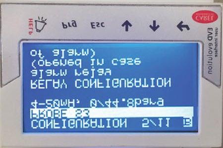
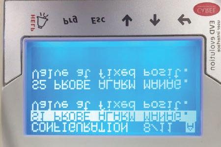
34 To change or view Configurations, press the PRG key, and enter password Configuration Menu WARNING: These menu screens are factory settings and are intended to be viewed only, not to be changed. If any values are different than shown here, please consult with Data Aire s Service Department. 34


35 35


36 Regulation Menu


37 7.3.4 How to Manually Open and Close an (EEV) This can be done in the Regulation Menu as shown below Step 1: Follow previous screens to the Regulation Menu screen below Step 2: Change Enable manual valve position from 0 to 1 and Manual valve position from 0stp to a desired step value. There are 480 steps total for the EEV. If you would like the valve to open 62.5%, enter 300stp such as below: 37


38 Step 3: Once all of the changes are done, press ESC on the main screen and verify the valve opening position. Step 4: Do not forget to revert the control back to automatic by changing the Enable manual valve position back to 0 from Multiple EEV Configuration For single circuit units, there will be one EEV and it will be shown as valve A. The letter A will be displayed on the top right corner of the EVD display screen, near the ON status. For a dual circuit units, there will be two EEVs and the second valve will be displayed as valve B. Set up for valve A does not affect settings for valve B, therefore, when the unit has two EEVs, set up for valve B is required. To setup valve B for circuit #2, press the two furthest keys simultaneously (ALARM + ENTER). The letter B will appear on the top right corner of the display. The display will now show the refrigerant status of circuit #2. Valve B must to be configured the same as Valve A in Configuration Menu and Regulation Menu. 38
NOTE: Special care should be given to those areas where these symbols appear.
 CONGRATULATIONS ON THE SELECTION OF A DATA AIRE PRECISION ENVIRONMENTAL CONTROL SYSTEM. PROPER INSTALLATION, OPERATION AND MAINTENANCE OF THIS EQUIPMENT WILL ENSURE YEARS OF OPTIMAL PERFORMANCE. There
Installation, Operation & Installation Manual. DX 7 to 46 kw
 GT by Installation, Operation & Installation Manual DX 7 to 46 kw Air and Water/Glycol Cooled Data Aire, Inc. 230 W. BlueRidge Avenue Orange, CA 92865 www.dataaire.com CONGRATULATIONS ON THE SELECTION
Large Ceiling Systems
 Large Ceiling Systems Installation, Operation & Maintenance Manual Air, Water and Glycol Cooled DX and Chilled Water 6, 8, 10 and 13 ton Data Aire, Inc. 230 W. BlueRidge Avenue Orange, CA 92865 www.dataaire.com
In Row Cooling Unit. Installation, Operation and Maintenance Manual. Chilled Water, Air and Water/Glycol Cooled Units
 In Row Cooling Unit Installation, Operation and Maintenance Manual Chilled Water, Air and Water/Glycol Cooled Units Data Aire, Inc. 230 W. BlueRidge Avenue Orange, CA 92865 www.dataaire.com M CONGRATULATIONS
DATA TEMP Installation, Operation and Maintenance Manual
 DATA TEMP Installation, Operation and Maintenance Manual Chilled Water 2-5 ton INSTALLATION OPERATION MAINTENANCE Chilled Water Cooled CONGRATULATIONS ON THE SELECTION OF A DATA AIRE PRECISION ENVIRONMENTAL
Data Aire, Inc. reserves the right to make design changes for the purpose of product improvement or to withdraw any design without notice.
 Data Aire, Inc. reserves the right to make design changes for the purpose of product improvement or to withdraw any design without notice. Table of Contents 1.0 Introduction 1.1 Inspection...4 1.2 Description...4
Operation and Maintenance Manual
 Operation and Maintenance Manual DX 21 to 106 kw Air and Water/Glycol Cooled CONGRATULATIONS ON THE SELECTION OF A DATA AIRE PRECISION ENVIRONMENTAL CONTROL SYSTEM. PROPER INSTALLATION, OPERATION AND MAINTENANCE
Service Step by Step Trouble-Shooting Check-List
 WARNING: Only Data Aire trained technician or experience technicians should be working on Data Aire Equipment. Protect yourself at all times and work safe. Date: Dates at the job site: From: to Job#: Serial#:
Mini-Plus. Installation, Operation and Maintenance Manual
 Mini-Plus Installation, Operation and Maintenance Manual Table of Contents 1.0 Installation... 6 1.1 Room Considerations... 6 1.2 Inspection... 6 1.3 Locating the Unit... 6 1.3.1 Horizontal Airfl ow Units...
DATA AIRE SERIES Operation and Maintenance Manual
 DATA AIRE SERIES Operation and Maintenance Manual DX 6-30 ton INSTALLATION OPERATION MAINTENANCE Air and Water/Glycol Cooled CONGRATULATIONS ON THE SELECTION OF A DATA AIRE PRECISION ENVIRONMENTAL CONTROL
PARALLEL RACK SYSTEM INSTALLATION & OPERATIONS MANUAL With Master Rack Compressor Sequencer
 PARALLEL RACK SYSTEM INSTALLATION & OPERATIONS MANUAL With Master Rack Compressor Sequencer 5/16 Rev. A 57-02509 2 Contents INTRODUCTION... 4 WARNING LABELS AND SAFETY INSTRUCTIONS... 5 PS SERIES PARALLEL
WMHP Series R410a Heat Pump INSTALLATION INSTRUCTIONS
 WMHP Series R410a Heat Pump INSTALLATION INSTRUCTIONS **WARNING TO INSTALLER, SERVICE PERSONNEL AND OWNER** Altering the product or replacing parts with non authorized factory parts voids all warranty
Installation Instructions
 24AHA4 Performance Series Air Conditioner with Puron Refrigerant 1-1/2 to 5 Nominal Tons Installation Instructions Fig. 1-24AHA4 A07532 SAFETY CONSIDERATIONS Improper installation, adjustment, alteration,
12 In Row. Installation Manual. MISSION CRITICAL Air Conditioning Systems. ClimateWorx International Inc.
 MISSION CRITICAL Air Conditioning Systems 12 In Row Installation Manual ClimateWorx International Inc. 14 Chelsea Lane, Brampton, Ontario, Canada L6T 3Y4 2 Table of Contents Table of Contents... 3 Site
DLCLRA. INSTALLATION INSTRUCTIONS Outdoor Unit Single Zone Ductless System Sizes 36 to 58 TABLE OF CONTENTS
 DLCLRA INSTALLATION INSTRUCTIONS Outdoor Unit Single Zone Ductless System Sizes 36 to 58 Fig. 1 - Size 36 TABLE OF CONTENTS PAGE SAFETY CONSIDERATIONS... 2 PARTS LIST... 3 SYSTEM REQUIREMENTS... 4 WIRING...
Condensing Unit Installation and Operating Instructions
 Bulletin WCU_O&I 01 June 2003 Condensing Unit Installation and Operating Instructions WCU Air Cooled Condensing Unit Table of Contents Section 1. Section 2. Section 3. Section 4. Section 5. Section 6.
SYSTEM 2000 CHILLED WATER (CAC) EC SERIES -INSTALLATION OPERATIONS AND MAINTENANCE MANUAL-
 EC SERIES -INSTALLATION OPERATIONS AND MAINTENANCE MANUAL-") SYSTEM 2000 CHILLED WATER (CAC) EC SERIES -INSTALLATION OPERATIONS AND MAINTENANCE MANUAL- 8167 Byron Road Whittier, CA 90606 Phone: (562) 945-8971 Fax: (562) 696-0724 www.compu-aire.com Table of Contents
SYSTEM 2000 CHILLED WATER (CAC) EC SERIES -INSTALLATION OPERATIONS AND MAINTENANCE MANUAL- 8167 Byron Road Whittier, CA 90606 Phone: (562) 945-8971 Fax: (562) 696-0724 www.compu-aire.com Table of Contents
CS/CD/CP AIR COOLED CONDENSING UNITS (P/N E207120C R2)
") CS*/CD*/CP* Series Air Cooled Condensing Units Operating and Installation Manual CS/CD/CP AIR COOLED CONDENSING UNITS (P/N E207120C R2) TABLE OF CONTENTS I. Receipt of Equipment 2 II. Piping...4 III. System
CS*/CD*/CP* Series Air Cooled Condensing Units Operating and Installation Manual CS/CD/CP AIR COOLED CONDENSING UNITS (P/N E207120C R2) TABLE OF CONTENTS I. Receipt of Equipment 2 II. Piping...4 III. System
Installation Instructions
 PREFERREDT SERIES AIR CONDITIONER WITH PURONR REFRIGERANT 1-1/2 TO 5 NOMINAL TONS Installation Instructions Fig. 1 --- 538A NOTE: Read the entire instruction manual before starting the installation. TABLE
TABLE OF CONTENTS. NOTE: Read the entire instruction manual before starting the installation. TROUBLESHOOTING... 13
 R 410A Duct Free Split System Air Conditioner and Heat Pump Product Family: DFS4(A/H) System, DFC4(A/H)3 Outdoor, DFF4(A/H)H Indoor NOTE: Read the entire instruction manual before starting the installation.
Series 6, Vertical Floor-Mount Units
 MISSION CRITICAL Air Conditioning Systems Series 6, Vertical Floor-Mount Units Installation Manual ClimateWorx International Inc. 14 Chelsea Lane, Brampton, Ontario, Canada L6T 3Y4 2 Table of Contents
Installation Instructions
 38MHR Outdoor Unit Single Zone Ductless System Sizes 09 to 24 Installation Instructions NOTE: Read the entire instruction manual before starting the installation. NOTE: Images are for illustration purposes
CROWN. Boiler Co. Santa-Fe Series. Hydronic Air Handlers INSTALLATION, OPERATION & MAINTENANCE INSTRUCTIONS
 CROWN Boiler Co Santa-Fe Series Hydronic Air Handlers INSTALLATION, OPERATION & MAINTENANCE INSTRUCTIONS These instructions must be affixed on or adjacent to the air handler Models: SAC049A20 SAC059A25
Installation Owner Diagnostics
 Installation Owner Diagnostics Split System Cooling Condensers Model CTA 7 1/2 to 15 Tons Models A and later Design Sequence CTA 090A***A 60 HZ 120A***A 60 HZ 120B***A 60 HZ 180B***A 60 HZ SS-SVN11A-EN
INSTALLATION AND OPERATIONAL MAINTENANCE MANUAL
 INSTALLATION AND OPERATIONAL MAINTENANCE MANUAL IN ROW SYSTEMS AYAN IV SERIES IN ROW COOLING 8176 Byron Road, Whittier, CA 90606 Phone: (562) 945-8971 Fax: (562) 696-0724 Website: www.compu-aire.com Email:
Standard and CELDEK Evaporative Cooler Modules Installation, Operation, and Maintenance Manual
 Standard and CELDEK Evaporative Cooler Modules Installation, Operation, and Maintenance Manual Standard Evaporative Cooler CELDEK Evaporative Cooler RECEIVING AND INSPECTION Upon receiving unit, check
G Series. G Series Air Coils Installation ti Manual ENCASED/UNCASED AIR COILS. Geothermal/Water Source Heat Pumps R-410A Refrigerant 2-5 Ton
 G Series ENCASED/UNCASED AIR COILS Geothermal/Water Source Heat Pumps R-410A Refrigerant 2- Ton Dimensional Data G Series Air Coils Installation ti Manual Installation Information Maintenance IM1018AG1
Standard and CELDEK Evaporative Cooler Modules Installation, Operation, and Maintenance Manual
 Standard and CELDEK Evaporative Cooler Modules Installation, Operation, and Maintenance Manual Standard Evaporative Cooler CELDEK Evaporative Cooler RECEIVING AND INSPECTION Upon receiving unit, check
COMPU KOOL III -INSTALLATION AND OPERATION MANUAL-
 COMPU KOOL III -INSTALLATION AND OPERATION MANUAL- 8167 Byron Road Whittier, CA 90606 Phone: (562) 945-8971 Fax: (562) 696-0724 www.compu-aire.com 1 AIR COOLED (CKA) WATER COOLED (CKW) GLYCOL COOLED (CKG)
Installation, Operation, and Maintenance Information
 Installation, Operation, and Maintenance Information Low Velocity Unit Coolers Bulletin No. IOM 110.3 Table of Contents Inspection... 2 Installation... 2 4 General... 2 Location... 2 Drain Line... 3 Refrigerant
NetworkAIR FM Precision Air Conditioner. Installation
 NetworkAIR FM Precision Air Conditioner Installation Contents General Information...1 Receiving the Equipment.............................. 1 Receive and inspect the Module...................... 1 Storing
INSTALLATION INSTRUCTIONS
 INSTALLATION INSTRUCTIONS T CLASS TSA Series 6 to 20 Ton AIR CONDITIONERS 6 20 TONS 506147 01 06/11 Supersedes 3/11 Litho U.S.A. RETAIN THESE INSTRUCTIONS FOR FUTURE REFERENCE IMPORTANT The Clean Air Act
User s Information and Installation Instructions
 Outdoor Air Conditioner User s Information and Installation Instructions 10 SEER Standard Efficiency Split System These units have been designed and tested for capacity and efficiency in accordance with
Installation Instructions
 CNPVP CNRVP Cased N Coils Upflow --- Downflow Heating --- Cooling Installation Instructions NOTE: Read the entire instruction manual before starting the installation. TABLE OF CONTENTS PAGE SAFETY CONSIDERATIONS...
38GHP AIR-COOLED MULTI SPLIT CONDENSING UNITS
 Concepcion Carrier Air conditioning Company Philippines INSTALLATION MANUAL, START-UP & SERVICE INSTRUCTIONS 38GHP AIR-COOLED MULTI SPLIT CONDENSING UNITS CONTENTS: Physical Data and Dimensions........
CELDEK Evaporative Cooler Module Installation, Operation, and Maintenance Manual. CELDEK Evaporative Cooler
 CELDEK Evaporative Cooler Module Installation, Operation, and Maintenance Manual CELDEK Evaporative Cooler RECEIVING AND INSPECTION Upon receiving unit, check for any interior and exterior damage, and
Horizontal/Side Discharge Condensing Units
 INSTALLATION, OPERATION & MAINTENANCE MANUAL Horizontal/Side Discharge Condensing Units Models CMA12SD-0 CMA18SD-1 CMA24SD-1 CMA30SD-1 CMA36SD-1 CMA48SD-1 517.787.2100 www.marsdelivers.com Horizontal/Side
Installation Instructions
 CNPVP CNRVP Cased N Coils Upflow --- Downflow Heating --- Cooling Installation Instructions NOTE: Read the entire instruction manual before starting the installation. TABLE OF CONTENTS PAGE SAFETY CONSIDERATIONS...
YCIV Hz & Hz
 YCIV 0590-1500 50Hz & 0157-0397 60Hz Start-up Checklist SERVICE POLICY & PROCEDURES Supersedes: Nothing Form 201.23-CL1 (309) Commissioning PREPARATION Commissioning of this unit should only be carried
P-Series, Vertical Floor-Mount Units
 MISSION CRITICAL Air Conditioning Systems P-Series, Vertical Floor-Mount Units Installation Manual ClimateWorx International Inc. 14 Chelsea Lane, Brampton, Ontario, Canada L6T 3Y4 - 2 - SP-IM2018 Table
INSTALLATION INSTRUCTIONS TXV Horizontal Slab Coils WLSH
 TXV Horizontal Slab Coils WLSH These instructions must be read and understood completely before attempting installation. It is important that the Blower and Duct System be properly sized to allow the system
PDF Created with deskpdf PDF Writer - Trial ::
 Instruction Manual Index Introduction Uncrating and Checking for Damage Locating Your Unit Installation Fill Tank Process Connections Pre Startup Startup Sequence Trouble Shooting Chart Operating Lights
Liebert CW Thermal Management System
 Liebert CW Thermal Management System 26 to 400 kw (7 to 114 ton) Capacity, Upflow and Downflow, 50 Hz and 60 Hz Installer/User Guide Technical Support Site If you encounter any installation or operational
INTRODUCTION. Special Applications of Package Air Conditioners. Instant Cooling Requirement in Wedding Ceremonies
 Pakistan s Largest Manufacturers of Air-Conditioners PACKAGE TYPE UNIT FOR MOBILE APPLICATIONS Provides Turnkey Projects Conceptual Planning to Commissioning of HVACR Projects THE LARGEST MANUFACTURER
Series 6, Vertical Floor-Mount Units
 MISSION CRITICAL Air Conditioning Systems Series 6, Vertical Floor-Mount Units Installation Manual ClimateWorx International Inc. 14 Chelsea Lane, Brampton, Ontario, Canada L6T 3Y4 2 Table of Contents
Installation Instructions
 Performance Series Heat Pumps with PURONr Refrigerant 1 --- 1/2 to 5 Nominal Tons Installation Instructions Fig. 1 --- A07532 NOTE: Read the entire instruction manual before starting the installation.
Installation, Operation, and Maintenance Information
 Installation, Operation, and Maintenance Information Air Cooled Condensers 8-2016 Rev 0 Table of Contents General Safety Information 2 Inspection 2 Installation 2 6 Rigging and Assembly 2 Unit Location
INSTALLATION AND OPERATING INSTRUCTIONS
 INSTALLATION AND OPERATING INSTRUCTIONS HIGH-EFFICIENCY CONDENSING UNITS RAWD- 6 1 2 & 7 1 2 TON RAWE - 6 1 2 & 7 1 2 TON! RECOGNIZE THIS SYMBOL AS AN INDICATION OF IMPORTANT SAFETY INFORMATION!! WARNING
Installation Instructions
 38MPRA Outdoor Unit Single Zone Ductless System Sizes 09 to 12 Installation Instructions NOTES: Read the entire instruction manual before starting the installation. Images are for illustration purposes
Installation Instructions
 8GXM / 0GXM Multi---Split High---Wall Duct Free Split System 8GXM --- Size 18k, k, and 0k 0GXM --- Size 9k, 1k, and 18k Installation Instructions NOTE: Read the entire instruction manual before starting
KITS COMMON TO HEATING AND COOLING EQUIPMENT 504,652M 03/04. Supersedes 503,249M
 2004 Lennox Industries Inc. Dallas, Texas KITS COMMON TO HEATING AND COOLING EQUIPMENT 504,652M 03/04 Supersedes 503,249M Litho U.S.A. COMPRESSOR REPLACEMENT KIT INSTALLATION INSTRUCTIONS FOR COMPRESSOR
WineZone Ceiling Mount Ductless Split 15
 WineZone Ceiling Mount Ductless Split 15 Requires an HVAC technician to install and charge with R-22 refrigerant. Easy to install. Unit plugs into wall outlet. Industrial grade unit for longer life. Indoor
PACKAGE AIR CONDITIONER
 PACKAGE AIR CONDITIONER FORM NO. ATZ-206 TZAA- HIGH EFFICIENCY SERIES NOMINAL SIZE 10 TON [35.2 kw] 10 TON MODEL [35.2 kw] This product is shipped with a nitrogen holding charge that must be vented prior
Daikin Direct Expansion (DX) Cooling Coils
 Cooling Coils") Installation and Maintenance Manual IM 902 Daikin Direct Expansion (DX) Cooling Coils Group: Applied Air Part Number: IM 902 Date: February 2008 Types EN, EF, ER, EJ, EK 2008 Daikin Applied Contents Introduction...
Installation and Maintenance Manual IM 902 Daikin Direct Expansion (DX) Cooling Coils Group: Applied Air Part Number: IM 902 Date: February 2008 Types EN, EF, ER, EJ, EK 2008 Daikin Applied Contents Introduction...
INSTALLATION AND OPERATIONAL MAINTENANCE MANUAL
 INSTALLATION AND OPERATIONAL MAINTENANCE MANUAL IN ROW NANO SYSTEMS CKC AYAN IV-IR NANO SERIES COMPU-AIRE, INC. 8176 BYRON ROAD, WHITTIER, CA 90606 IN ROW COOLING PHONE: (562) 945-8971 FAX: (562) 696-0724
User s Information and Installation Instructions
 Outdoor Air Conditioner User s Information and Installation Instructions 13 SEER R-410A High Efficiency Split System These units have been designed and tested for capacity & efficiency in accordance with
Condensing Unit Installation and Operating Instructions
 Bulletin ACU_O&I 02 August 2016 Condensing Unit Installation and Operating Instructions ACU Air Cooled Condensers Table of Contents Section 1. General Information... 2 Section 2. Refrigeration Piping...
Some of these procedures need to be performed to conform to requirements of the Clean Air Act.
 Leak Detection, Recovery, Evacuation and Charging Four basic service procedures used to repair and maintain a mechanical refrigeration system are leak detection, evacuation, recovery, and refrigerant charging.
Data Aire LCS TM (Large Ceiling System) R-407C. 6, 8, 10, and 13 ton. ISO 9001 Certified
 R-407C. 6, 8, 10, and 13 ton. ISO 9001 Certified") Data Aire LCS TM (Large Ceiling System) 6, 8, 10, and 13 ton ISO 9001 Certified LCS TM (LARGE CEILING SYSTEMS) with refrigerant Product Description Performance and Electrical Data Dimensional Data Guide
Data Aire LCS TM (Large Ceiling System) 6, 8, 10, and 13 ton ISO 9001 Certified LCS TM (LARGE CEILING SYSTEMS) with refrigerant Product Description Performance and Electrical Data Dimensional Data Guide
Mortex INSTALLATION INSTRUCTIONS AIR CONDITIONING & HEAT PUMP INDOOR COILS
 Mortex INSTALLATION INSTRUCTIONS AIR CONDITIONING & HEAT PUMP INDOOR COILS INTRODUCTION Please note that HUD Manufactured Home Construction and Safety Standard Section 3280.714, paragraph (a) and subparagraph
Installation, Start-Up and Service Instructions
 38AH044-134 Air-Cooled Condensing Units 50/60 Hz Installation, Start-Up and Service Instructions CONTENTS Page SAFETY CONSIDERATIONS...................... 1 INSTALLATION................................
Data Aire LCS TM (Large Ceiling System) R-410A. 6, 8, 10, and 13 ton. ISO 9001 Certified
 R-410A. 6, 8, 10, and 13 ton. ISO 9001 Certified") Data Aire LCS TM (Large Ceiling System) 6, 8, 10, and 13 ton ISO 9001 Certified LCS TM (LARGE CEILING SYSTEMS) DX Product Description Performance and Electrical Data 3 the pioneer and builder of the most
Data Aire LCS TM (Large Ceiling System) 6, 8, 10, and 13 ton ISO 9001 Certified LCS TM (LARGE CEILING SYSTEMS) DX Product Description Performance and Electrical Data 3 the pioneer and builder of the most
Liebert CRV Warranty Inspection Check Sheet
 The following information must be fully completed and forwarded to your local Liebert sales office to establish your equipment warranty. Installer Address Owner Address Owner e-mail address Date of Installation
Installation Instructions
 Evaporator Coil A Coil --- Cased Multipoise NOTE: Read the entire instruction manual before starting the installation. TABLE OF CONTENTS PAGE SAFETY CONSIDERATIONS... 1 INTRODUCTION... 1 INSTALLATION...
AHG**-0B Series Hydronic Air Handling Units
 HEAT CONTROLLER, INC. Installation, Operation and Maintenance Manual Installation, Operation and Maintenance Manual AHG**-0B Series Hydronic Air Handling Units HEAT CONTROLLER, INC. 1900 Wellworth Ave.,
SECTION PACKAGED ROOFTOP AIR CONDITIONING UNITS
 SECTION 15732 - PACKAGED ROOFTOP AIR CONDITIONING UNITS PART 1 - GENERAL 1.1 SECTION INCLUDES A. Package roof top unit. B. Heat exchanger. C. Refrigeration components. D. Unit operating controls. E. Roof
EarthLinked SW Series Compressor Unit R-410A Quik-Start Instructions
 EarthLinked SW Series Compressor Unit R-410A Quik-Start Instructions CONTENTS PAGE Pre-Installation 3 Placement & Mechanical Information 4 System Application Options 10 Antifreeze Protection 14 Electrical
KR Series Air Defrost Unit Coolers Operating and Installation Manual
 KR Series Air Defrost Unit Coolers Operating and Installation Manual KR Air Defrost Unit Coolers (PN E108317_L) TABLE OF CONTENTS 1 RECEIPT OF EQUIPMENT... 2 1.1 INSPECTION... 2 1.2 LOSS OF GAS HOLDING
C13-Series Engineering Guide
 Engineering Guide Effective January 2018 Horizontal Air-Cooled, Water-Cooled, Chilled Water and Heat Pump Contents Product Features............................... 3 Product Options................................
R.A.S.E.R.S System. Installation Guide
 R.A.S.E.R.S System Installation Guide Contents R.A.S.E.R.S System components... 1 Required components for heating, cooling, and hot water...1 Provided...1 Not provided...2 Optional components...3 R.A.S.E.R.S
AIR CONDITIONING. Carrier Corporation 2002 Cat. No
 AIR CONDITIONING Carrier Corporation 2002 Cat. No. 020-016 1. This refresher course covers topics contained in the AIR CONDITIONING specialty section of the North American Technician Excellence (NATE)
INSTALLATION GUIDE. 4AC 14* ASA1 SERIES R-410a CONDENSING UNITS R-410A ATTENTION, INSTALLER! ATTENTION, USER!
 4AC 14* ASA1 SERIES R-410a CONDENSING UNITS INSTALLATION GUIDE R-410A ATTENTION, INSTALLER! After installing the system, show the user how to turn off electricity to the unit. Point out control and switch
SPX SERIES PACKAGED AIR CONDITIONING/HEAT PUMP UNITS INSTALLATION, OPERATION AND MAINTENANCE INSTRUCTIONS
 SPX SERIES PACKAGED AIR CONDITIONING/HEAT PUMP UNITS INSTALLATION, OPERATION AND MAINTENANCE INSTRUCTIONS **WARNING TO INSTALLER, SERVICE PERSONNEL AND OWNER** Altering the product or replacing parts with
OWNER S MANUAL. Vintage Signature Series models: AC750, AC1050, AC1100, AC1250, AC1500, AC1750. Proudly Made in the USA.
 OWNER S MANUAL Vintage Signature Series models: AC750, AC1050, AC1100, AC1250, AC1500, AC1750 Proudly Made in the USA support@aquacomfort.com 888-475-7443 Manufacturing High Quality, High Efficiency Heat
EarthLinked SCW Series Compressor Unit R-410A Quik-Start Instructions
 EarthLinked SCW Series Compressor Unit R-410A Quik-Start Instructions CONTENTS PAGE Pre-Installation 3 Placement & Mechanical Information 6 System Application Options 12 Antifreeze Protection 13 Electrical
Liebert Challenger 3000/Liebert Challenger ITR with Liebert icom Control. Operation & Maintenance Manual - 50 & 60Hz
 Liebert Challenger 3000/Liebert Challenger ITR with Liebert icom Control Operation & Maintenance Manual - 50 & 60Hz TABLE OF CONTENTS IMPORTANT SAFETY INSTRUCTIONS................................ INSIDE
I N STALLATIO N. VRC Series IOM-M Part Number
 M ECHANICAL I N STALLATIO N O PERATION & MA I NTENANCE VRC Series IOM-M2-0916 Part Number 478603 Table of Contents Safety... 3 Special Design Requests... 3 Model Number Guide... 3 Clearances... 4 Lifting
TECHNICAL GUIDE DESCRIPTION SPLIT-SYSTEM AIR-COOLED CONDENSING UNITS MODELS: HF-07 FEATURES B-0703
 TECHNICAL GUIDE SPLIT-SYSTEM AIR-COOLED CONDENSING UNITS MODELS: HF-07 DESCRIPTION These Sunline 2000 units are completely assembled, piped and wired at the factory to provide one-piece shipment and rigging.
INSTALLATION INSTRUCTIONS TXV Horizontal Duct Coils EHD
 TXV Horizontal Duct s EHD These instructions must be read and understood completely before attempting installation. It is important that the Blower and Duct System be properly sized to allow the system
Installation Instructions
 40MAQ High Wall Ductless Split System Sizes 09 to 36 Installation Instructions NOTE: Read the entire instruction manual before starting the installation TABLE OF CONTENTS PAGE SAFETY CONSIDERATIONS 2 PARTS
TABLE OF CONTENTS INTRODUCTION. NOTE: Read the entire instruction manual before starting the installation.
 Installation NOTE: Read the entire instruction manual before starting the installation. TABLE OF CONTENTS PAGE SAFETY CONSIDERATIONS... 1 INTRODUCTION... 1 INSTALLATION... 2 Inspect Equipment... 2 Select
SECTION AIR COILS
 PART 1 - GENERAL 1.1 RELATED DOCUMENTS A. Drawings and general provisions of the Contract, including General and Supplementary Conditions and Specification Sections, apply to this Section. B. Related Sections:
APPLICATION GUIDELINES FOR COPELAND COMPLIANT SCROLL COMPRESSORS (ZR*1 Models)
") 4-1280 Application Engineering Bulletin AE-1280R4 Revised April, 1995 APPLICATION GUIDELINES FOR COPELAND COMPLIANT SCROLL COMPRESSORS (ZR*1 Models) Introduction The Compliant Scroll Compressor has been
4-1280 Application Engineering Bulletin AE-1280R4 Revised April, 1995 APPLICATION GUIDELINES FOR COPELAND COMPLIANT SCROLL COMPRESSORS (ZR*1 Models) Introduction The Compliant Scroll Compressor has been
TECHNICAL MANUAL CX(E) SPLIT SYSTEMS. Tel: Fax:
 SPLIT SYSTEMS. Tel: Fax:") TECHNICAL MANUAL CX(E) SPLIT SYSTEMS CONTENTS INDEX PART NUMBERS, OPTIONS, UNIT COMBINATIONS, DIMENSIONS & WEIGHTS 3 PERFORMANCE DATA & AIR FLOW 4 SOUND POWER AND SOUND PRESSURE LEVELS 5 ELECTRICAL DATA
TECHNICAL MANUAL CX(E) SPLIT SYSTEMS CONTENTS INDEX PART NUMBERS, OPTIONS, UNIT COMBINATIONS, DIMENSIONS & WEIGHTS 3 PERFORMANCE DATA & AIR FLOW 4 SOUND POWER AND SOUND PRESSURE LEVELS 5 ELECTRICAL DATA
Guide Specifications for InRow Direct Expansion
 Guide Specifications Guide Specifications for InRow Direct Expansion THIS GUIDE SPECIFICATION IS WRITTEN IN ACCORDANCE WITH THE CONSTRUCTION SPECIFICATIONS INSTITUTE (CSI) MASTERFORMAT. THIS SECTION MUST
INSTALLATION INSTRUCTIONS TXV Coils for Manufactured Housing EMA
 TXV Coils for Manufactured Housing EMA NOTE: Read the entire instruction manual before starting the installation. SAFETY CONSIDERATIONS Improper installation, adjustment, alteration, service, maintenance,
INSTALLATION INSTRUCTIONS
 INSTALLATION INSTRUCTIONS R 410A Ducted Horizontal Air Conditioner Product Family: HC4A3 Fig. 1 - HC4A3 NOTE: Read the entire instruction manual before starting the installation. TABLE OF CONTENTS PAGE
EarthLinked HC Series Compressor Unit R-410A Quik-Start Instructions
 EarthLinked HC Series Compressor Unit R-410A Quik-Start Instructions CONTENTS PAGE Pre-Installation 3 Placement & Mechanical Information 4 System Application Options 11 Antifreeze Protection 14 Electrical
INSTALLATION INSTRUCTIONS
 INSTALLATION INSTRUCTIONS T CLASS TPA Series HEAT PUMPS 7.5 TO 10 TONS 506148 01 12/08 Litho U.S.A. RETAIN THESE INSTRUCTIONS FOR FUTURE REFERENCE IMPORTANT The Clean Air Act of 1990 bans the intentional
National Comfort Products 539 Dunksferry Road Bensalem, PA (215) Fax: (215)
 Fax: (215)") National Comfort Products 539 Dunksferry Road Bensalem, PA 19020 (215) 244-1400 1-800-523-7138 Fax: (215) 244-9579 R410a SPLIT-SYSTEM CONDENSING UNIT INSTALLATION INSTRUCTIONS 1000 3000 4000 SERIES 1.
National Comfort Products 539 Dunksferry Road Bensalem, PA 19020 (215) 244-1400 1-800-523-7138 Fax: (215) 244-9579 R410a SPLIT-SYSTEM CONDENSING UNIT INSTALLATION INSTRUCTIONS 1000 3000 4000 SERIES 1.
INSTALLATION INSTRUCTIONS TXV Coils EDM, EDD, EDA
 TXV Coils EDM, EDD, EDA These instructions must be read and understood completely before attempting installation. It is important that the Blower and Duct System be properly sized to allow the system to
Calhoon MEBA Engineering School. Study Guide for Proficiency Testing Refrigeration
 Calhoon MEBA Engineering School Study Guide for Proficiency Testing Refrigeration 1. To prevent an injury when working with refrigerants, what safety precautions are necessary? 2. When halogens are in
Installation Instructions
 40MBD Ducted Style Ductless System Sizes 09 to 48 Installation Instructions NOTE: Read the entire instruction manual before starting the installation. TABLE OF CONTENTS PAGE SAFETY CONSIDERATIONS... 2
XC13. IMPORTANT Operating pressures of this R 410A unit are higher than pressures in R 22 units. Always use service equipment rated for R410A.
 Service Literature Corp. 0521 L9 Revised 09 2007 XC13 SERIES UNITS XC13 The XC13 is a high efficiency residential split system condensing unit, which features a scroll compressor and R 410A refrigerant.
Installation, Start-Up and Service Instructions
 38AH044-134 Air-Cooled Condensing Units 50/60 Hz Installation, Start-Up and Service Instructions CONTENTS Page SAFETY CONSIDERATIONS...................... 1 INSTALLATION................................
gforce Units Data Aire and Data Temp Series
 gforce Units gforce gforce is the most advanced mission critical cooling equipment available on the market today. These units are the most efficient and economical while complying with strict environmental
Installation Instructions
 25HHA4 Performance Series Heat Pump with Puron Refrigerant 1-1/2 to 5 Nominal Tons Installation Instructions Fig. 1-25HHA4 A07532 SAFETY CONSIDERATIONS Improper installation, adjustment, alteration, service,
UHIR Series. Horizontal or Vertical Mounting Industrial / Commercial Electric Unit Heater. Owner s Manual
 UHIR Series Horizontal or Vertical Mounting Industrial / Commercial Electric Unit Heater Owner s Manual This manual covers installation, maintenance and repair parts. Read carefully before attempting to
Bulletin , March Electric Hot Gas Bypass Valves
 Bulletin 100-60, March 2018 Electric Hot Gas Bypass Valves PAGE 2 / Bulletin 100-60 10 FEATURES AND BENEFITS SDR-4 Direct temperature control Tight shutoff when closed Can be interfaced with direct digital
Operation Manual SCT14B and SCT18B. Inspection. 3 General Description. 3 General Requirements. 3 Standard Features.
 Spot Cooling Systems, Inc. 120 Century Drive Suite 00 Carrollton, TX 7006 00-6-776 Operation Manual SCT1B and SCT1B Warning! Improper installation, adjustment, alteration, service, or maintenance can cause