UniAir UniBraz UniCompact UniGasket UniSystem UniTwist UniWeld
|
|
|
- Maud Bryant
- 6 years ago
- Views:
Transcription
1 INSTRUCTIONS FOR PLATE HEAT EXCHANGERS UniGasket UNEX HEATEXCHANGER ENGINEERING GMBH. AUSTRIA Tel: +43 (0) Fax: +43 (0) UniGasket_TD_EN_ /24
2 CONTENTS 1) PRINCIPLE AND CONSTRUCTION 3 1.1) PRINCIPLE OF THE PLATE HEAT EXCHANGER 3 1.2) CONSTRUCTION OF THE PLATE HEAT EXCHANGER 3 2) FUNCTION 4 2.1) FUNCTION OF THE PLATE HEAT EXCHANGER 4 2.2) ASSEMBLY DRAWING 5 2.3) DIAGRAM (FIG. 8) 6 3) MOUNTING INSTRUCTION 8 3.1) ASSEMBLING OF EDGE- CLAMPED FRAME 8 3.2) MOUNTING REQUIREMENTS 8 4) START-UP ) PROCEDURE FOR START-UP ) PROCEDURE DURING OPERATION ) PROCEDURE FOR STOP ) TROUBLE-SHOOTING 12 5) MAINTENANCE AND CLEANING ) SEPARATION ) CLEANING ) ASSEMBLING ) REPLACEMENT OF PLATES AND GASKETS ) RECONSTRUCTION 22 6) SPARE PARTS AND ACCESSORIES ) ORDERING PROCEDURE ) ACCESSORIES 24 UniGasket_TD_EN_ /24
 CONSTRUCTION OF THE PLATE HEAT EXCHANGER 1. Head 2. Top bar 3. Follower 4.")
3 1) PRINCIPLE AND CONSTRUCTION 1.1) PRINCIPLE OF THE PLATE HEAT EXCHANGER A plate heat exchanger consists of an edge clamped frame within which a number of cold pressed plates are compressed. These are made with special corrugations which ensures turbulent flow and high heat transfer coefficients. 1.2) CONSTRUCTION OF THE PLATE HEAT EXCHANGER 1. Head 2. Top bar 3. Follower 4. End support 5. Flow plate 6. Plate pack 7. Bottom bar 8. Tie bolts 9. Connector grid 10. Connector boss Example of plate heat exchanger coated with stainless steel. Connector grid (9) and connector bosses (10) are only used in plate heat exchangers with two or more sections. UniGasket_TD_EN_ /24
 PLATES After clamping of the plate pack, the plates which are fitted with gaskets ensure, an effective seal between fluids and atmosphere (fig. 2).")

.")

4 2) FUNCTION 2.1) FUNCTION OF THE PLATE HEAT EXCHANGER 2.1.2) CONNECTOR GRIDS Connector grids must be inserted in a plate heat exchanger operating simultaneously with several media ) PLATES After clamping of the plate pack, the plates which are fitted with gaskets ensure, an effective seal between fluids and atmosphere (fig. 2). In addition, intermixing of the fluids is eliminated by a double gasket seal around the inlet ports (fig. 3). Every second plate is turned through 180 degrees. This means that the double gasket seal occurs around every second inlet to the channels between the plates. The plate pack now forms a series of parallel flow channels in which the fluids flow in a counter current regime (fig. 4). These connector grids divide the plate heat exchanger in separated sections. The connector grids are equipped with exchangeable connector bosses (fig. 5). The connector bosses form the connecting link between the respective sections of the plate heat exchanger and/or connections for pipes. Two connecting branches can be provided in the same connection boss with connection to their respective section ) SEPARATING PLATES Plate heat exchangers with more than one section requiring no inlet/outlet branches in the separation can be equipped with separating plates (strong sheet, 2-10 mm) or flow plates equipped with reinforced blankings. UniGasket_TD_EN_ /24
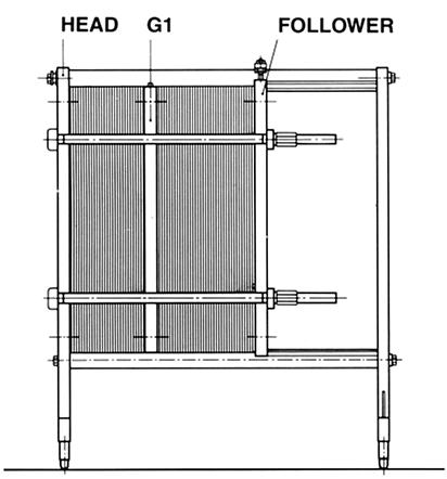
5 2.2) ASSEMBLY DRAWING Normally, an assembly drawing will be attached to the plate heat exchanger. This shows all principal dimensions as well a connection specifications and identification. Figures 6 a-b-c show examples of the construction of a plate heat exchanger: HEAD = Head G = Connector grid FOLL. = Follower H = Horizontal connection V = Vertical connection 1 section 1 pass 1 section 2 passes 5 sections horizontally oriented corner hole number connector grid number from head (HEAD) connector grid UniGasket_TD_EN_ /24
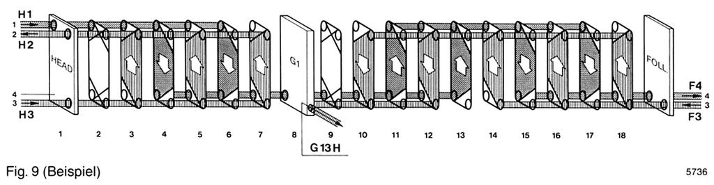
6 2.3) DIAGRAM (FIG. 8) 2.3.1) CONFIGURATION OF THE DIAGRAM The plate pack is suspended between the head and the follower. The gasket side of the plates must always face towards the head. On the right-hand side of fig 8. can be seen a single plate viewed from the gasket side. The corner holes of the plate are designated 1-4. Inter-connecting lines have been drawn from the plate pack to the four corner holes of the plate. The flow channels for each fluid are marked with a thick or a thin line to ease identification ) EXAMPLE Figs. 7, 8 and 9 show the same plate heat exchanger with a heating and cooling section separated by a connector grid G1. The cold fluid enters the heating section via H1 in the head and flows through two parallel channels in one pass before entering the cooling section via hole 4 in the connector grid. From here the fluid is cooled in two passes, each with two parallel channels, before leaving the plate heat exchanger through F4 in the follower. The heating medium enters through head (H3 in HEAD) and leaves again through head (H2 in HEAD). The cooling medium enters through follower (F3 in FOLL.) and leaves through the connector boss of the connector grid (G13H) ) REFERENCE NUMBER AND PUNCH CODE The material quality and the four first digits of the reference number of the plate are stated in the top left-hand corner of the diagram fig. 8 (No. 1075). The four last digits of the eight-digit reference number are placed on the plate together with a punch code. The code indicates which corner holes are open to allow fluid flow. For example: 1204* means that this plate is open in corners 1, 2, and 4, whereas corner 3 (marked with 0) is closed. The letter H at the top is explained in section ) SERIAL NUMBERS The numbers of the diagram under the plates are serial numbers, i.e. indication of the placing of the plates in the plate heat exchanger. Serial numbers start with number 1 for the head and after that continuous numbers for each plate, connector grid, or separating plate. When extending the plate pack, the existing numbers are used, but the new plates are marked with an extra figure, e.g. 16, 17, 18, 18-1, 18-2, 18-3, 18-4, 19, 20 etc ) REFERENCE NUMBERS AND GASKETS The diagram gives the reference number of gaskets for each section in the plate heat exchanger as well as quantity and reference numbers for glue and cleaning fluid for a complete replacement of all gaskets ) CAPACITY The data list on the diagram gives the capacities and other criteria used for the design of the plate heat exchanger. UniGasket_TD_EN_ /24
7 UniGasket_TD_EN_ /24
8 3) MOUNTING INSTRUCTION 3.1) ASSEMBLING OF EDGE-CLAMPED FRAME 3.1.1) Start by erecting the head (HEAD). Secure the bottom bar (E) to the head by bolts and block it up (1), bolt the end support (2) on the bottom bar (E). spanner (8) or a similar suitable tool. Start clamping with two tie bolts diagonally opposite each other. These tie bolts can be tightened almost to the minimum plate pack dimension. Continue by clamping all the tie bolts in a diagonal manner. Keep the head and the follower as parallel as possible during clamping and check at all tie bolts! (max. deviation 10 mm per m distance between the tie bolts). The minimum clamped plate pack dimension is shown on the machine plate on the head ) Place the follower (FOLL.) on two blocks (3) approx. 200 mm from the head (HEAD). Place two spacer blocks (4) at the top between the head and the follower. Retain the follower (FOLL.) with a rope (R), and remove the scotching (1) ) Bolt the top bar (C) on the end support and the head with the fittings (5) ) Fit the fittings with rollers (6) on the follower (FOLL.) so that the rollers are exactly opposite each other. Mount the bottom bar fitting (7) on the follower. Adjust the height of the follower by means of the roller fittings. Remove the blocks (3 and 4) and the rope (R) ) Push the follower to the end support. Worm the plates (A) on. The top bar one by one, turn thern over the bottom bar, and push thern towards the head. Insert the plates in serial-numerical order as stated in the diagram. The serial numbers must be upwards and the gasket side must face towards the head ) When all the plates have been correctly assembled, push the follower against the plate pack mount the tie bolts (H) apply a high pressure lubricant to the threaded ends of the tie bolts. Clamping should be carried out using a ratchet UniGasket_TD_EN_ /24
9 3.2) MOUNTING REQUIREMENTS The plate heat exchanger should be placed in such a way that service and inspection can easily be effected ) SPACE REQUIRED On a least one side of the plate heat exchanger there must be sufficient space to unhook the plates from the top bar by a slight tilt away from the vertical. At the same time it must be possible to tighten or remove the tie bolts and inspect the plate heat exchanger (fig. 11). It must be possible to take off the spray screen or insulating jacket, if any, without having necessarily to remove the connecting pipes. This must be considered when installing the unit. All engagements are carried in a straight pipe section without thermometer, manometer or draw off taps at a distance of 100 mm from the unit (more in case of increased insulating thickness). The distance to finish-insulated pipes should be 100 mm from the insulating jacket/spray screen. The follower must be free to move along the full length of the top bar as shown in fig. 10. See dimensions for exactly your plate heat exchanger at the back of this manual ) PIPE CONNECTIONS The plate heat exchanger must be connected up according to the enclosed assembly drawing. Threaded connections should be mounted with unions or flanges with plane tightening to facilitate removal alternatively with conical tightening connected to bends. Flanged connections must be removable. Fig. 12 shows a correctly connected unit. If necessary, a suitable filter should be installed on the fluid inlet. Insulating valves are also recommended on all connections. Thermometers, pressure gauges etc. should be used as required for monitoring the plate heat exchanger performance ) CORRECT PIPE MOUNTING (Fig. 12) To prevent undue strain on the plate heat exchanger frame, all pipes must be unloaded by suitable pipe holders. The pipe joints on the follower (FOLL.) 1 and 2 must be removable in order to enable the plate heat exchanger to be opened for cleaning and inspection. For re-tightening of the plate pack, the pipes onto the follower and any connector grids must be flexible. This can be achieved by the use of expansion joints. During opening, it must be possible to move the follower 3, without hindrance, along the full length of the top bar. For CIP (cleaning in place), without opening, piping material and layout must be chosen accordingly. UniGasket_TD_EN_ /24
10 3.2.4) PRESSURE PUL- SATIONS/VIBRATIONS Piston pumps, gear pumps, dosing devices etc. must not be able to transfer pressure pulsations/vibrations to the plate heat exchanger as this may cause fatigue fracture in the plates ) EXCESS PRESSURE PROTECTOR Excess pressure protector must always be mounted (fig. 13), if the plant is likely to develop a higher pressure than that stated on the machine plate. This condition may arise during pump start up, expansion or valve change-over etc ) SHIELDING The plate pack must be shielded, when: possible splashes may cause damage corrosive media are being used the working temperature may cause scalding required by the local authorities Spray screens for all plate heat exchanger types can be supplied. When thermal shielding is desirable or required, an insulating jacket can be supplied. This jacket fits the heat exchanger exactly and can be taken off without removing the connecting pipes ) DRAIN Ideally a drain should be located close to the plate heat exchanger. If the drain leads to public sewage system, the possible risk of pollution should be considered. If either fluid cannot run directly to drain, suitable spill trays should be placed beneath the unit. If necessary, these should be fitted with a level alarm ) LIQUID HAMMERING The plate heat exchanger is sensitive to liquid hammering. This can occur during regulation, change-over, pump start-up etc., see section In order to avoid this situation, the use of throttling of airoperated valves, damping relays in electrical control gear, automatic pump start with closed valves etc. is recommended. UniGasket_TD_EN_ /24
11 4) START-UP 4.1) PROCEDURE FOR START UP Before the initial start-up, check that the clamped plate pack dimension is as specified on the machine plate on the plate heat exchanger ) START-UP Sudden surges and drops in pressure and temperature must be avoided, as these may damage the plates and gaskets thereby causing leakage. Pumps should be started against closed valves which can then be gradually opened until the desired flow rate is achieved. NOTE!!! The initial start-up of plate heat exchangers with new EPDM gaskets must be effected by increasing the temperature slowly, max. 25 C (77 F) per hour. By restart-up and stop, the following must be observed: Pressure surge/drop must not exceed ±10 bar per minute. Temperature increase/drop must not exceed ±10 C per minute. If the above precautions are not observed, the guarantee will no longer apply. In a plate heat exchanger using steam as the heating media, the cold fluid should be introduced to the plate heat exchanger before the steam is turned on. The potential damage possible due to the incorrect start-up increases proportionally with increased liquid flows and the length of connecting pipework! 4.1.2) LEAKAGE DURING START-UP During the initial start-up, minor leaks may occur until the plates and gaskets have reached their design working temperature and all sections are correctly pressurised ) VENTING When correct working temperature and working pressure have been reached, the system must be vented. The air in the plate heat exchanger is driven out by the liquid flow, provided that the capacity is as stated in the diagram. Air in a plate heat exchanger reduces the heat transmission and increases the pressure drop, thus increasing the risk of corrosion! 4.1.4) PERMISSIBLE PRESSURE Working, and testing pressures are given on the machine plate. WORKING PRESSURE = the highest pressure to which the plate heat exchanger may be subjected during operation! TESTING PRESSURE = the pressure at which the plate heat exchanger may be tested! For start-up of plate heat exchangers with grafoseal gaskets, see section UniGasket_TD_EN_ /24
12 Pressure testing is made as a differential pressure i.e. warm and cold side separately. For plate heat exchangers with several sections, the stated working, testing, and differential pressures only apply if all sections are pressurised. If each section operates at different pressures, or one of the sections is not under pressure, leaks may occur in the lower pressure section. The maximum permissible difference in pressure between two sections separated by a connector grid or a separating plate is in general 6 kp/cm². If the two sections are not equal in size, the permissible difference is reduced. The maximum difference in pressure depends on the number of plates in the other section/s. 4.2) PROCEDURE DURING OPERATION During operation, temperatures and pressure drops must be regularly checked. Increased pressure drop and/or failing temperatures indicate that there are coatings on the plates. The plate heat exchanger now needs cleaning. During operation, the same precautions against rises of pressure must be observed as during start-up! 4.2.1) LEAKAGE DURING OPERATION See section 4.4) TROUBLE-SHOOTING. 4.3) PROCEDURE FOR STOP is stopped, and the cooling fluids are shut off. Finally, the product pump is stopped. If the plate heat exchanger is to be opened, it must be cooled below 40 C by letting the product pump re-circulate and lowering the temperature of the circulating water by max. 10 C per minute. This is done by opening for the cooling water or adding cold water to the circuit. Plate heat exchangers with 1 section are closed down slowly so that the temperature decreases by max. 10 C per minute. If there is no other possibility of cooling, the plate heat exchanger can be cooled with corporation water below 40 C. Normally, the plate heat exchanger can be unpressurised by shutting off the fluid inlets and outlets. The temperature will gradually decrease to the ambient temperature. For long working breaks, see procedure in section ) TROUBLE-SHOOTING In case of damage to plates or gaskets, it will often be necessary to replace them. First examine very carefully the external conditions around the plate heat exchanger in order to localise the cause of the damage! In case of fatigue fracture, this will normally necessitate a replacement of all plates and gaskets as there may be a risk of fatigue fracture in all the material. In case of corrosion, all plates must be examined carefully! In plate heat exchangers for pasteurising, the steam is shut off, the hot-water pump UniGasket_TD_EN_ /24
13 4.4.1) VISIBLE LEAKAGE Type of irregularity: Possible cause: Remedy of irregularity: Leakage Leakage (Phase 1) Leakage (Phase 2) Leakage (Even after tightening of the plate heat exchanger to minimum dimension). Leakage (Through the drain holes of the gaskets). The pressure is too high Insufficient tightening Fouled or deformed plates Inelastic or deformed gaskets. Gaskets Defective gasket or badly corroded plate. Reduce the pressure to the correct working pressure, which can be found on the machine plate. Tighten up the plate heat exchanger (section 5.1) however, not below the minimum dimensions and never, when the plate heat exchanger is under pressure or over 40 C. If the plate heat exchanger is still leaking proceed with phase 2. Separate the plate heat exchanger (section 5.1) and check if the plates are deformed or fouled. Check the gaskets are elastic and nondeformed, and that the faces of the joints are clean. Replace deformed plates and gaskets, if any, see ordering procedure (section 6.1). Before assembling, clean all plates and gaskets very carefully (section 5.2). Assemble the plate heat exchanger (section 5.3) and start it up again (section 4.1). Note!!! Even tiny impurities such as sand grains may cause leakage. Separate the plate heat exchanger (section 5.1). Clean the plates very carefully (section 5.2). Replace the gaskets. Assemble the plate heat exchanger (section 5.3) and start it up again (section 4.1). Separate the plate heat exchanger (section 5.1). Replace defective plates and gaskets, if any. Assemble the plate heat exchanger (section 5.3) and start it up again (section 4.1). UniGasket_TD_EN_ /24
14 4.4.2) NON-VISIBLE LEAKAGE Type of irregularity: Reduced heat transmission and/or increasing pressure drop. Leakage. (The fluids get mixed). (Phase 1). Leakage. (The fluids get mixed). (Phase 2). Possible cause: Fouled plates or choked plate channels. Corrosion or fatigue fracture. Holes in plates. Corrosion or fatigue fracture. Remedy of irregularity: Separate the plate heat exchanger (section 5.1) and check if the plates are fouled. Clean the plates very carefully (section 5.2). Assemble the plate heat exchanger (section 5.3) and start it up again (section 4.1). A suspected leakage can be localised in the following way: Remove one of the lower pipe connections. Then put the opposite side under pressure. If the medium continues to run out of the lower pipe connections after the pressure has stabilised one or several plates are leaking. Close down the plate heat exchanger (section 4.3). Separate the plate heat exchanger (section 5.1) and check the plates very carefully. Check suspected plates with a dye penetrant. Check defective plates and gaskets, see ordering procedure (section 6.1). Before assembling, clean all plates and gaskets (section 5.2). Assemble the plate heat exchanger (section 5.3) and check to find more defective plates, if any, by putting one side under pressure. Start up again (section 4.1). Close down the plate heat exchanger (section 4.3). Separate the plate heat exchanger (section 5.1). Put all plates to dry. Suspend the plates in the plate heat exchanger again and tighten it (section 5.3). Circulate medium at full capacity on one plate side (every second plate channel). Keep the other plate channels unpressurised and free from liquid! Stop the circulation after some minutes of operation and open the plate heat exchanger again. Take care to avoid water spraying onto the dry plate side! By a careful study of the plates it will be possible to find moist areas, if any, on the otherwise dry plate sides. Check these areas with a dye penetrant! Replace defective plates and gaskets, see ordering procedure (section 6.1). Before assembling, clean all plates and gaskets (section 5.2). Assemble the plate heat exchanger (section 5.3) and check to find more defective plates, if any, by putting one side under pressure. Start up again (section 4.1). If the unit is still leaking, check all plates with a dye penetrant! UniGasket_TD_EN_ /24
15 5) MAINTENANCE AND CLEANING 5.1) SEPARATION 5.1.1) COOLING AND PRESSURE RELIEF Before opening the plate heat exchanger, it must be cooled down to below 40 C (104 F), and it must not be pressurised! Cooling must not exceed 10 C per minute. The pressure drop must not exceed 10 bar per minute. If these standards are disregarded, the guarantee will no longer apply! 5.1.2) SEPERATION OF EDGE- CLAMPED FRAME On completion of the procedure in section 5.1.1, separate the frame by keeping two, perhaps four diagonally placed tie bolts clamped. Dismount the rest of the tie bolts. NOTE. Take care that the follower does not keel over! Loosen the last tie bolts uniformly (max. 10 mm per m distance in difference), then push the follower towards the end support (fig. 14). NOTE. When using plate heat exchangers on board ships, the follower must be secured in order to avoid danger during the movements of the ship ) PLATE HEAT EXCHANGERS WITH GRAFOSEAL GASKETS When plate heat exchangers fitted with grafoseal gaskets are separated, these gaskets should normally be replaced by new ones. However, if the plate heat exchanger is opened, cleaned and tightened with care so that the plate sequence is unchanged and no graphite material is removed from the plate behind, the gasket can be used again. The maximum pressure will, however, be reduced somewhat. In case of replacement of a plate, the gasket in the plate behind this plate must be replaced as well. Grafoseal gaskets should always be handled with great care to avoid damage of the gasket surface. NOTE. Never bend a grafoseal gasket! 5.2) CLEANING The capacities and resistance to corrosion of plate heat exchangers depend on the plate pack being kept clean. Fouling on the plates can be removed manually or by CIP (cleaning in place) ) MANUAL CLEANING Clean the plates with a soft brush and a suitable detergent (section 5.2.4). In case of thick layers of scale or organic materials, the plates must be put in a bath of detergent (section 5.2.4). NOTE. Never use steel brush, metal scraper or the like. A high-pressure cleaner can be used with care however, never with sand or other abrasives added. UniGasket_TD_EN_ /24
16 5.2.2) CIP-CLEANING A circulation system, in which a suitable detergent can be circulated is established. If the product to be flushed out has a high viscosity, the circulating quantity must be big enough to reach a sufficient speed for flushing out the product. If the product pump is volumetric, it may be necessary to insert a pump for the detergent parallel to the former. It is assumed that the fouling on the plates are soluble in a detergent which does not attack plates and gaskets. Example of CIP-cleaning: Drain off product residues and cooling and heating media. Rinse with cold or lukewarm water. Circulate with warm cleaning fluid solution. Rinse with warm water. Rinse with warm water with softener added to it. Rinse with cold or lukewarm water. Cleaning can also be effected without circulation by pouring a cleaning fluid solution into the system. After some time of standing, wash out the detergent with clean water ) CONTROL OF CLEANING The plate heat exchanger must be opened for inspection at regular intervals. This is necessary especially during the running-in period, until experience has been gained on the effectiveness of the cleaning process. With these inspections, it will gradually be possible to determine circulation times, temperatures, and chemical concentrations with great certainty! Insufficient cleaning is most often due to: too small circulation quantity. too short cleaning period. too small chemical consumption in relation. too the fouling on the plates. too long periods of operation. If the plate heat exchanger is out of operation for a long time, it is advisable to empty it, separate the plates, and clean the unit. Clamp the plate heat exchanger lightly together, and leave it covered in order to protect the gaskets against dirt and the effect of light! 5.2.4) DETERGENTS The definition of a suitable detergent is brief and to the point. Coatings on the plates must be removed without damaging plates and gaskets. It is important not to decompose the passivating (protective) film of stainless steel the film contributes to preserving the resistance of the steel to corrosion. Do not use chlorine-containing agents such as hydrochloric acid (HCI)!!! EXAMPLES: OIL AND FATS are removed with a water emulsifying oil solvent, e.g. BP-SYSTEM CLEANER. ORGANIC AND GREASY COATINGS are removed with SODIUM HYDROXIDE (NaOH) max. concentration 1.5% - max. temperature 85 C (185-F). 1.5% concentration corresponds to 3.75 litre 30% NaOH per 100 litre water. UniGasket_TD_EN_ /24
17 FURRINGS AND SCALE DEPOSITS are removed with NITRIC ACID (HN03) max. concentration 1.5% - max. temperature 65 C (149 F). 1.5% concentration corresponds to 1.75 litre 62% HN03 per 100 litres water. Nitric acid has an important constructive effect on the passivating film of stainless steel ) CONTROL OF CLEANING FLUID CONCENTRATION SODIUM HYDROXIDE (NaOH) solution is titrated with 0.1 n HYDROCHLORIC ACID (HCI) with methyl orange or methyl red as indicator. NITRIC ACID (HN03) solution is titrated with 0.1 n SODIUM HYDROXIDE (NaOH) with phenolphtalein as indicator. The concentration of the cleaning fluid in % can be calculated from the titration result according to the following formula: CONCENTRATION = b n m % a 10 a = b = n = m = ml cleaning fluid taken out for titration ml titration fluid used for change of colour normality of titration fluid molecular weight of cleaning fluid (NaOH) molecular weight 40 HN03 molecular weight 63. In order to use the correct quantity of chemicals for CIP cleaning, the cleaning fluid should be checked immediately before flushing. If the concentration is too low, <0.5%, the plate heat exchanger is probably not clean. If the concentration is too high, >1%, the chemical consumption can be reduced. UniGasket_TD_EN_ /24

18 ASSEMBLING 5.3.1) ASSEMBLING If the plates have been dismounted, they must be correctly inserted according to serial numbers! The head has No. 1, and the serial numbers of the following plates and the connector grids, if any, are 2, 3, 4, 5 etc. The serial number is marked in the top right-hand corner of the plates do not forget that the gasket side must face towards the head. In the case of single pass non-food PHEs the serial number is not stamped on to the plate. 1. Minimum dimension +15% - 2 hours interval or more. 2. Minimum dimension +7.5% - 12 hours interval or more. 3. A dimension between max. and min. dimension as stated on the machine plate, alternatively min. dimension. The head and the follower must be exactly parallel. Therefore, clamping must be measured at the top, in the middle, and the bottom on both sides ) CLAMPING The maximum and minimum dimension for clamping is stated on the machine plate, which is placed on the head. The plate heat exchanger must be clamped to dimension between max. and min. dimension. The final clamping to minimum dimension is recommended after approx. one month s operation alternatively, immediately after installing new plate heat exchangers/new gaskets. New gaskets in EPDM quality are clamped step-wise the first time: Plate heat exchangers with Grafoseal gaskets, see section UniGasket_TD_EN_ /24


19 5.4) REPLACEMENT OF PLATES AND GASKETS 5.4.1) MARKING The plates are marked with material codes and reference number plus codes for nonglue gasket, if any, and also have the letter H (fig. 16). Looking towards the gasket side, the plate is designated a right plate when the H is upwards and a left plate when the H is downward. Left plates have inlet and outlet via corner holes 1 and 4, respectively (fig. 17). Material code Serial number (please state when ordering single plates). In the case of single pass non-food PHEs the serial number is not stamped on the plate. Four last digits of H Four last digits of the reference num- the reference number of the plate. ber of the plate (only on plates for non-glue gasket). Right plates have inlet and outlet via corner holes 2 and 3, respectively. H = right plate )REPLACEMENT OF PLATES Before inserting a spare plate in the plate pack, it must be checked that the spare plate is identical with the defective plate the same corner holes open, and the mark H must face right. If the width of new plates is not the same as that of the plates they are to replace or of those of the plate pack being extended, the widest plates are to be fitted at the back of the plate pack, if possible; adjacent to the grid, separator plate or follower. New plates always differ from old plates. Therefore, new plates are to be grouped together, if possible. As an example, the current, nominal width of K-range plates is 483 mm. Previously it was smaller. A defective 4-hole plate can be removed from the plate pack without inserting a spare plate, if the adjoining 4-hole plate is also removed. The new number of plates will then be = S-2. This changes the clamping measure of the plate pack to M1 which will be: M1 = M (S-2) S M = The original clamping dimension stated on the machine plate. S = The original number of plates in the plate pack. UniGasket_TD_EN_ /24
 REPLACEMENT OF GLUED GASKETS The first plate after the head and the connector grid must have a gasket in all groves.")
20 The transmission area of the plate heat exchanger is reduced in relation to the original number of plates. At the same time, the pressure drop will increase. As to corrosion and fatigue fracture of plates, see section 4.4 trouble shooting. Ordering procedure for plates can be found in section ) REPLACEMENT OF GLUED GASKETS The first plate after the head and the connector grid must have a gasket in all groves. These gaskets are, in fact, two normal gaskets cut in half and glued in place around all grooves. You should carefully note how the old gaskets are assembled before removing them! METHYL ETHYL KETONE or ETHYL ACETATE. It is important that all the degreasing agent has evaporated, before the glue is applied. This will normally take approx. 15 min. at 20 C (68 F). It is advisable to clean the gluing surfaces of the gaskets with fine-grain sandpaper instead of degreasing agent ) GLUING PLIOBOND 25, which is a nitrile rubber glue on solvent basis (25% solids), is applied with a brush in a thin layer on the backs of the gaskets ) REMOVAL OF OLD GASKETS PLIOBOND glued gaskets can be loosened by heating in water at 100 C (212 F). The plates are cleaned, and coatings, if any, are removed. See section ) CLEANING New gaskets and the gasket grooves of the plates are cleaned with a cloth moistened with degreasing agent. The gluing surfaces must be absolutely clean without finger prints etc. As degreasing agent use what is stated on the enclosed diagram. Alternatively, use: TRICHLOROETHYLENE, CHLOROTHENE VG, ACETONE, The gaskets are put to dry in a clean and dust free place! The gasket grooves of the plate are now coated with a thin layer of glue, and the gaskets are cemented into the grooves. The insertion of gaskets starts at both ends of the plate and continues with the straight sections along the edges. The gluing process is most easily effected by laying the gaskets and the plates on a table as the gaskets are cemented into the grooves of the plates, the plates should be stacked. The plates with the gaskets are now suspended in the frame which is clamped lightly, for rubber gaskets e.g. to the minimum dimension indicated on the machine plate plus 0.2 mm per plate. UniGasket_TD_EN_ /24

21 The plate heat exchanger is heated to C ( F) by means of water or steam the temperature must be kept for 1 ½ - 2 hours! The liquid pressure must be kept as low as possible. On the plate heat exchangers for food, pipe branches which are not connected to water / steam must be kept free, in order to permit glue vapours to escape! If there is no possibility of heating the plate heat exchanger, it must stand at a place as warm as possible with dismounted connections. The drying time will at 20 C (68 F) be approx. 48 hours. At e.g. 40 C (104 F), the drying time is reduced to approx. 24 hours. When the glue vapours have vaporized, the plate heat exchanger can be clamped again as stated in section ) NON-GLUE PARACLIP GASKETS PARACLIP is a non-glue gasket designed as a conventional gasket. It is designed with a special clip-on feature which locks it into recesses in the gasket groove on the plate. When replacing PARACLIP gaskets, the old gasket is removed completely. Before fitting the new PARACLIP gasket, check that the plate gasket groove is clean and free from residual rubber, particularly in the clip-on pockets. New gaskets can be fitted without using tools. The first plate after the head and the connector grids, which have no physical contact with the product, are equipped with a glued gasket as described, see section UniGasket_TD_EN_ /24


22 However, it will seldom be necessary to change these as their only purpose is to fill out the gasket groove thereby supporting the rest of the plate pack. The PARACLIP gasket is available for food as well as non-food purposes. When assembling, the EPDM quality gasket should be wiped with a cloth wetted with silicone oil to facilitate the separation from the connecting plate when disassembling the plate pack. In case of reconstruction, all the customer has to do is to state the type designation, serial number and the wanted change. UNEX Systems has all relevant data in file and can immediately submit a suggestion and a quotation for the reconstruction. 5.5) RECONSTRUCTION The modular construction of the plate heat exchanger ensures an easy extension or reduction in the capacity. UniGasket_TD_EN_ /24
23 6) SPARE PARTS AND ACCESSORIES 6.1) ORDERING PROCEDURE When ordering plates, please state the serial numbers of the plates and the type and serial number of the plate heat exchanger. The serial numbers of the plates can be found in the top right-hand corner of the plates (fig. 16) the type and serial number of the plate heat exchanger can be taken from the machine plate! In the case of single pass non-food PHEs the serial number is not stamped on to the plate. ORDER EXAMPLE: 4 plates with glued-on gaskets, serial numbers 11, 12, 13, and 14 plate heat exchanger type H17 serial number ORDER EXAMPLE OF A COMPLETE SET OF PLATES: 1 complete set of plates with glued-on gaskets plate heat exchanger type M 107 serial number MATERIAL CODE: CODE DESIGNATON PREVIOUSLY USED CODE A B S T X Y Z Stainl. steel AISI 304 Stainl. steel AISI 316 Stainl. steel W (Avesta 832 SL) Titanium ASTM B 265 grade 1 Stainl. steel W (Avesta 254 SLX) Stainless steel (Avesta 254 SMO) HASTELLOY C 276 Monel Cu-Al C E G J M R D F H K N P ORDER EXAMPLE OF A COMPLETE SET OF PLATES FOR ONE SECTION: 1 complete set of plates with glued-on gaskets for the heat recovery section plate heat exchanger type K 55 serial number The plates are marked with a material code (fig. 16) symbolizing the steel quality. The four digits after the letter are UNEX s internal press operation number (threedigit number and a letter). When knowing the material code, UNEX Systems can procure a certificate of the plate. U M UniGasket_TD_EN_ /24
 SPRAY SCREENS")


24 6.2 ACCESSORIES 6.2.1) SPRAY SCREENS 6.2.2) INSULATING JACKET 6.2.3) CLAMPING TOOLS UniGasket_TD_EN_ /24
PLATE HEAT EXCHANGER
 PLATE HEAT EXCHANGER Type Sxx-xx-xx Serie-No.: xxxxx/xx/x Operating & maintenance Contents page Construction and function 2 Plate construction 3 Plate type 4 Drawings and name plate 5-6 Gasket construction
PLATE HEAT EXCHANGERS. Operation and Maintenance Manual
 PLATE HEAT EXCHANGERS Operation and Maintenance Manual Operation and Maintenance Manual TABLE OF CONTENTS A. Plate Heat Exchanger Description B. Construction and Function C. Plate Characteristics D. Gasket
Installation, Operation and Maintenance Instructions for ThermaFlex Gasketed Plate Heat Exchangers
 OM010 Installation, Operation and Maintenance Instructions for ThermaFlex Gasketed Plate Heat Exchangers The operating and maintenance instructions contained within this package are for ThermaFlex gasketed
Installation, Operation and Maintenance Instructions ThermaFlex Gasketed Plate Heat Exchanger OM010
 Installation, Operation and Maintenance Instructions ThermaFlex Gasketed Plate Heat Exchanger OM010 Calorifiers Heat Exchangers Pressurisation Units Sales Tel: 01457 835700 Sales Fax: 01457 832700 E-mail:
Rycroft Supapac Plate Heat Exchangers
 Rycroft Supapac Plate Heat Exchangers Installation Operation & Maintenance Manual Ormandy Rycroft Duncombe Road Bradford BD8 9TB England TEL +44 (0)1274 490911 FAX +44 (0)1274 498580 www.rycroft.com 1.
Operation and Maintenance Manual Sondex All-Welded Heat Exchangers (SAW)
") Operation and Maintenance Manual Sondex All-Welded Heat Exchangers (SAW) The contents of this publication are based on the latest information available and the materials that are used at the time of printing.
Operation and Maintenance Manual Sondex All-Welded Heat Exchangers (SAW) The contents of this publication are based on the latest information available and the materials that are used at the time of printing.
HRS Heat Exchangers Instruction Manual
 HRS Heat Exchangers Instruction Manual Plate Heat Exchanger Ceteplate HRS032, HRS140, HRS150, HRS220 and HRS240m Information courtesy of Cetetherm Table of contents Table of contents Description... 1 Main
ANLAGENBAU HEAT EXCHANGER w w w. a nla g enba u-b oehm er. d e Version 05/2015
 ANLAGENBAU HEAT EXCHANGER Table of Contents 1.0 General Information 1.2 User Instructions 1.3 Proper Use 1.4 General Safety Rules 2.0 Design and Function 3.0 Installation 3.1 Setting up the Plate Heat
Channel plates Heat is transferred from one medium to the other through the thin channel plates.
 Description English Description Main components Frame plate Carrying bar Carries the channel plates and the pressure plate. Support column Tightening bolts Press the channel plates together. Bolt protection
Description. Main components. Lifting eyes To used for lifting and transport securing. Carrying bar Carries the cassettes and the pressure plate.
 Description English Description Main components Lifting eyes To used for lifting and transport securing Frame plate Carrying bar Carries the cassettes and the pressure plate. Support column Connections
Operation of heat exchangers
 Operation of heat exchangers Delivery to site, downloading, receipt/acceptance Check state Transport on site Storage Short term Long term Installation Requirements of installation area Adjustment Connection
Installation, Operation and Maintenance LOK-FLANGE Multitube Heat Exchangers
 Bulletin 1200/4 (Revised 5/12) Installation, Operation and Maintenance LOK-FLANGE Multitube Heat Exchangers INNOVATORS IN HEAT TRANSFER I. INSTALLATION OF HEAT EXCHANGERS A. HEAT EXCHANGER SETTINGS 1)
OHMS ENTERPRISE Subsidiary of AIT Synergy Ventures SDN BHD
 OHMS ENTERPRISE Subsidiary of AIT Synergy Ventures SDN BHD Welcome to OHMS ENTERPRISE Cost effective, reliable service and quality spare parts for plate heat exchangers worldwide OHMS ENTERPRISE is specialized
Instruction Manual Plate Condenser. AlfaCond 400/600/800. Part number
 Instruction Manual Plate Condenser AlfaCond 400/600/800 Part number 34502490 0904 Table of contents English Table of contents Description... 1 Main components... 1 Function... 2 Installation... 3 Requirements...
WesPlate. Operation, Maintenance & Installation Manual. Heat Exchanger. Models WP & WPDW
 WesPlate Heat Exchanger Models WP & WPDW Operation, Maintenance & Installation Manual TABLE OF CONTENTS Section 1.0 Plate Heat Exchangers Working Principle 2.0 Parts & Their Function 2.1 Frames 2.2 Plates
Aston Technology-Sondex A/S PHE - Design & Datalist V10A34 Aston Thomas McLaughlin 05/03/ ATESHEX S1 Item: 1
 Aston Technology-Sondex A/S PHE - Design & Datalist V10A34 Aston Thomas McLaughlin 05/03/2015 425 3968 ATESHEX S1 Item: 1 PHE-Type S130-IS16-212-TMTL16-LIQUID Hot side Cold side Flowrate (kg/s) 62.76 105.85
Titanium Plate Heat Exchanger. Installation & Operating Manual
 Titanium Plate Heat Exchanger Installation & Operating Manual Congratulations on your purchase of your Elecro Titanium PLATE HEAT EXCHANGER, manufactured in Hertfordshire, England to exacting standards
Instruction Manual. Pharma-line ESE02198-EN Original manual
 Instruction Manual Pharma-line ESE02198-EN 2012-05 Original manual Table of contents The information herein is correct at the time of issue but may be subject to change without prior notice 1. Description...
M3 M6 M10 TS6 T2 T5 TL3 TL6
 DE Instruction Manual Plate Heat Exchangers M3 M6 M10 TS6 T2 T5 TL3 TL6 FR ES PT IT SV DA FI NL RU PL NO Part number 1644725-01 0810 Table of contents Table of contents Description... 1 Main components...
Instruction and Maintenance Manual. Spiral Heat Exchanger
 Instruction and Maintenance Manual Spiral Heat Exchanger 1. Content Description... Section 2 Introduction... Section 3 Important safety Precautions... Section 4 Generally... Section 5 Correct Installation...
Technical Data TYPE T14 & T14D TEMPERATURE PILOT SPENCE ENGINEERING COMPANY, INC. 150 COLDENHAM ROAD, WALDEN, NY SD 4511A T14 PILOT
 Technical Data SD 4511A SPENCE ENGINEERING COMPANY, INC. 150 COLDENHAM ROAD, WALDEN, NY 12586-2035 TYPE T14 & T14D TEMPERATURE PILOT PRINTED IN U.S.A. SD 4511A/9811 5 13 /16 D 4 7 /8 1 13 /16 T14 PILOT
PLATE HEAT EXCHANGERS
 PLATE HEAT EXCHANGERS QUALITY TECHNOLOGY SERVICE As a result of the researches on effectiveness and cost, many different types of heat exchangers have been developed as an alternative to conventional shell
Chemical Motor Pump Unit BN
 Operating & Maintenance Instructions BW 5 02 01 / 1 The operating instructions of the centrifugal pump and the accessories should be located close to the pump. These instructions should be read carefully
AIC Brazed Plate Heat Exchanger Operating and Instruction Manual
 AIC Brazed Plate Heat Exchanger Operating and Instruction Manual Advanced Industrial Components Page 1 of 8 Customer Service Call: 1-888-738-1350 1.0 Installation 1.1 Mounting/support unit: a) On a shelf
Plate Type Heat Exchangers. Operation and Maintenance Manual
 Plate Type Heat Exchangers Operation and Maintenance Manual Project: Customer: Exchanger type: Serial number: Year: PED category: Art. 3, par.3 Cat. 1 Cat. 2 Cat. 3 Cat. 4 Approved by: NB number: Remarks:
Evaporators. Direct Expansion Flooded Recirculated Over Feed
 Evaporators Purpose: Liquid Refrigerant is Boiled from a Low Pressure Liquid to a Low Pressure Gas by Absorbing Heat from the Medium that is being Cooled Types: Direct Expansion Flooded Recirculated Over
TABLE OF CONTENTS FOR YOUR SAFETY
 TABLE OF CONTENTS 1. SPECIFICATION & PARTS IDENTIFICATION...2 2. OPERATION & FUNCTION OF PARTS...2, 3 A. Cooling Operation B. Heating Operation C. Function of Parts 3. LOCATION REQUIREMENTS...3, 4 4. INSTALLATION
COPYRIGHT Alfa Laval Lund AB, 2012 How to contact Alfa Laval Contact details for all countries are continually updated on our website.
 Table of Contents English Table of Contents Description... 5 Main components... 5 Name plate... 6 Function... 7 Multi-section... 8 Multi-pass... 9 Identification of plate side... 9 Installation... 10 Before
Instruction Manual - Plate Heat Exchangers
 EN Instruction Manual - Plate Heat Exchangers IT M15, TL10, TL15, T20, TS20, MX25, MA30, WideGap 100, WideGap 200 FI LT 3490017598-EN 2016-06 Original manual Table of contents EN Preface... 4 Safety considerations...
VERTICAL GLANDLESS PUMP
 VERTICAL GLANDLESS PUMP INSTALLATION, OPERATION AND MAINTENANCE MANUAL INDEX Sl.No CONTENTS Page No. 1 Introduction 02 2 Unpacking 04 3 Installation procedure for VGP (Pump dispatched without motor) 07
CADDY 5 UL OPERATOR S MANUAL
 CADDY 5 UL CADDY ENGLISH 10 UL OPERATOR S MANUAL CADDY 1 TECHNICAL CHARACTERISTICS Read electrical ratings written on the data plate under the individual units. The serial number of the unit is preceded
eng ger fre Instruction Manual Plate Heat Exchangers spa M3 M6 M10 TS6 TL6 por ita swe dan fin dut rus pol Part number nor
 ger Instruction Manual Plate Heat Exchangers M3 M6 M10 TS6 TL6 fre spa por ita swe dan fin dut rus pol Part number 1644725-01 0502 nor Table of contents English Table of contents Description... 1 Main
AUC Cell Washer. User Manual
 AUC Cell Washer User Manual WARRANTY Spin Analytical Inc., warrants this product to be defect free in both material and workmanship for 90 days from the date of shipment. Labor services are guaranteed
Brazed Plate Heat Exchanger Operations Manual
 razed Plate Heat Exchanger Operations Manual razed Exchanger Operations Manual razed Heat Exchangers from Polaris deliver exceptional strength and performance in a compact package. These versatile units
The theory behind heat transfer
 Alfa Laval in brief Alfa Laval is a leading global provider of specialized products and engineered solutions. Our equipment, systems and services are dedicated to helping customers to optimize the performance
Electron Microscopy Sciences
 Electron Microscopy Sciences INSTRUCTIONAL MANUAL CAT. 71260-10 through 71260-17 Cabinet Style Lab Companion Vacuum Desiccators sgkcck@aol.com P.O. Box 550, 1560 Industry Road, Hatfield, PA 19440 Safety
4 route 147, C.P.33 Coaticook, Qc J1A 2S8
 4 route 147, C.P.33 Coaticook, Qc J1A 2S8 TABLE OF CONTENTS INSTALLATION Nozzles p.3 Clearance for dismantling p.4 Foundations p.4 Foundation bolts p.5 Leveling p.5 Bolted joints p.5 Recommended bolt tightening
Steam Trap BK 45 BK 45-U BK 45-LT BK 46
 Steam Trap BK 45 BK 45-U BK 45-LT BK 46 Original Installation Instructions 810437-08 Contents Foreword... 3 Availability... 3 Formatting features in the document... 3 Safety... 3 Use for the intended purpose...
IN THE PULP AND PAPER INDUSTRY
 H E A T E X C H A N G E R S BULLETIN NO. TIS-105A PRIME SURFACE PLATE & FRAME ALL-WELDED PLATE IN THE PULP AND PAPER INDUSTRY THE heat transfer people H E A T E X C H A N G E R S 2 TRANTER BRINGS EFFICIENCY
SCHMIDT- BRETTEN GASKETED PLATE HEAT EXCHANGERS
 SCHMIDT- BRETTEN GASKETED PLATE HEAT EXCHANGERS API Schmidt-Bretten Leadership in plate heat exchangers since 1879. API Schmidt-Bretten traces its roots to 1879 in Germany when company founder Wilhelm
- 1 - Updated on 18 March, 2010
 - 1 - Updated on 18 March, 2010 TABLE OF CONTENTS 1. SPECIFICATION & PARTS IDENTIFICATION...3 2. OPERATION & FUNCTION OF PARTS...4, 5 A. Cooling Operation B. Heating Operation C. Function of Parts 3. LOCATION
UltraHeat Plate and Frame Heat Exchangers. Engineered for Excellence
 UltraHeat Plate and Frame Heat Exchangers Engineered for Excellence Graham Corporation traces its history to the earliest development of heat transfer products in the United States during the 1920s, when
G-10f/GCG-10f UPRIGHT COOLER
 G-Series Cooler G-10f/GCG-10f UPRIGHT COOLER Manual is for the following models: G-10F, G-10-F33EB GCG-10F, GCG-10-F33EB GCG-10F2, GCG-10-F233EB G-10-F33EB-HC, GCG-10-F33EB-HC GCG-10-F233EB-HC Instruction
GEM TRAP FITTING & MAINTENANCE INSTRUCTIONS
 GEM TRAP FITTING & MAINTENANCE INSTRUCTIONS IMPORTANT Please read these instructions before fitting any traps. The following pages describe how each type of GEM Trap should be installed. If you are unsure
INSTALLATION AND OPERATING INSTRUCTIONS General operating instructions for sample gas conditioner Model: MAK 6
 List of contents 1.0 Uses 2.0 Technical data 2.1 Operating data 2.2 Construction and installation 2.3 Climatic load 2.4 Power supply 3.0 Function and design 3.1 General comments 3.2 Design 3.3 Performance
Thermostatic mixing valves with interchangeable cartridges
 www.caleffi.com R37. Thermostatic mixing valves with interchangeable cartridges Installation, commissioning and servicing instructions 3 Series Function The thermostatic mixing valve is used in systems
This chapter is devided into two sections:
 This chapter is devided into two sections: Page Installation requirements........................................................................ 127 The installation process..........................................................................
Plastic plate heat exchanger
 2014US - 7.3.1 PWT-plastic Plastic plate heat exchanger Applications POLYBLOC is the right choice for highly corrosive pollutants. Plate heat exchangers in exhaust systems for brine baths, electroplating
Operation Manual R205BV, R209BV
 Operation Manual R205BV, R209BV 1 Safety Instruction The rotary evaporator is manufactured according to current methods and accepted safety regulations. However, risks still exist during the installation,
Operating Instructions
 Operating Instructions Sake Warmer Dispenser TSK-0A TSK-20A TSK-220A TSK-420A TSK-30A TSK-230A TSK-0A TSK-30A Contents Introduction... Use... Names of Parts... 2 Inspection and Preparation Before Use...
PowerVent. Installation manual (GB) English. Store this document in a safe place UK
 English. Store this document in a safe place UK") PowerVent Installation manual (GB) Store this document in a safe place 959.034.03.UK GB Contents Blz Foreword 3 1. Introduction 3 2. CE declaration 4 3. SAFETY 4 3.1 General 4 3.2 Regulations 4 3.3 Precautions
PowerVent Installation manual (GB) Store this document in a safe place 959.034.03.UK GB Contents Blz Foreword 3 1. Introduction 3 2. CE declaration 4 3. SAFETY 4 3.1 General 4 3.2 Regulations 4 3.3 Precautions
EVAC Commercial Marine Equipment TOILET TECHNICAL DATA EVAC 90, SQUATTING TOILET. To main vacuum line, connection Ø50.
 Date: 25 Jan 2005 Doc. 1:114E TECHNICAL DATA 5979301 EVAC 90, SQUATTING To main vacuum line, connection Ø50 Service door 600 Push button Fresh water supply connection 1/2" MPT BSP 700 700 Flushing mechanism
Installation and operating instructions. DK energy storage and DK energy buffer
 Installation and operating instructions DK energy storage and DK energy buffer Edition: 08-2015 1 Preliminary note With this DK energy storage / DK energy buffer you purchased a DK quality product. The
FC 5 FC 5 Premium. OPERATOR MANUAL Floor Cleaner...2 MANUAL DE USUARIO Limpiador de piso...22 MANUEL D UTILISATION Nettoyant pour sols...
 FC 5 FC 5 Premium OPERATOR MANUAL Floor Cleaner.................2 MANUAL DE USUARIO Limpiador de piso............22 MANUEL D UTILISATION Nettoyant pour sols...........44 59682960 2018.03 FLOOR CLEANER
Hot Chocolate Dispenser
 Hot Chocolate Dispenser Instruction manual Model: CN219-A AU Telephone Helpline: 1300225960 Safety Tips Position on a flat, stable surface. A service agent/qualified technician should carry out installation
APV ParaFlow Plate Heat Exchangers
 APV ParaFlow Plate Heat Exchangers A history of excellence, innovation and expertise A look back. And forward. For more than 75 years, APV Systems has provided customers worldwide with the latest technology,
541D19 SERIES. Technical Manual. A Division of Aquion Partners L.P.
 541D19 SERIES Technical Manual A Division of Aquion Partners L.P. Table of Contents Introduction... Page 1 Technical Specifications... Page 2 Flow Diagrams... Page 3 Injector & Flow Control Selection Injector...
Installation, Operation and Maintenance Instructions for Thermax Semi-Storage Calorifier
 OM001 Installation, Operation and Maintenance Instructions for Thermax Semi-Storage Calorifier These operating and maintenance instructions are for standard semi-storage calorifiers (vessels fitted with
User s Information Manual
 User s Information Manual Series 2 Models 1000-2000 MBH Commercial Condensing Gas-fired water boilers If the information in this manual is not followed exactly, a fire or explosion may result, causing
Installation, Operation and Maintenance Instructions for Electric Storage Calorifier
 OM004 Installation, Operation and Maintenance Instructions for Electric Storage Calorifier The operating and maintenance instructions contained within this package are for standard electric storage calorifiers
PRO 2000i LOW LEVEL DEPOSITOR
 DEPOSITORS AND AUTOMATED CAKE PRODUCTION SYSTEMS PRO 2000i LOW LEVEL DEPOSITOR OPERATION AND SPARE PARTS MANUAL Serial No. PR2L- (Please quote this number when ordering spares, and making service calls)
USER AND MAINTENANCE MANUAL
 USER AND MAINTENANCE MANUAL CONTENTS PAGE 1 - GENERAL 4 1.1 Preface 4 1.2 Regulations 4 1.3 Warranty 5 1.4 Residual risks 5 1.5 Receiving the unit 6 1.6 Handling 6 1.7 Intended use 7 1.8 Description 8
- 1 - Updated on 18 March, 2010
 - 1 - Updated on 18 March, 2010 TABLE OF CONTENTS 1. SPECIFICATION & PARTS IDENTIFICATION...3 2. OPERATION & FUNCTION OF PARTS...4, 5 A. Cooling Operation B. Heating Operation C. Function of Parts 3. LOCATION
INFINITY FLUIDS CORPORATION
 INFINITY FLUIDS CORPORATION INFINITY FLUIDS CORPORATION 344 FRANKLIN STREET WORCESTER, MA 01522 888-565-8137 508-347-3674 CRES PRODUCT: WATER/LIQUID HEATER AIR/GAS HEATER INLINE/INSTANTANEOUS STEAM GENERATORS
ECONOPLATE BARE PLATE HEAT EXCHANGERS
 ECONOPLATE BARE PLATE HEAT EXCHANGERS INSTALLATION, OPERATION & MAINTENANCE DOCUMENTATION STOKVIS ENERGY SYSTEMS 34 CENTRAL PARK ESTATE 34 CENTRAL AVENUE WEST MOLESEY SURREY KT8 2QZ TEL: 020 8783 3050
INSTRUCTIONS FOR USE. To make the most of your new oven, read the user's instructions carefully and keep them on hand for consultation in the future.
 INSTRUCTIONS FOR USE INSTALLATION...4 SAFEGUARDING THE ENVIRONMENT... 7 IMPORTANT NOTES... 7 BEFORE USING THE OVEN... 8 OVEN ACCESSORIES... 9 CARE AND MAINTENANCE... 10 TROUBLESHOOTING GUIDE... 12 AFTER
GCG-9. Instruction Manual. G-Series Cooler. Manual is for the following models: GCG-9-N13EB G-9-N13EB GCG-9-B13EB UPRIGHT COOLER
 G-Series Cooler UPRIGHT COOLER Manual is for the following models: -N13EB G-9-N13EB -B13EB Instruction Manual FOR YOUR FUTURE REFERENCE This easy-to-use manual will guide you in getting the best use of
HX Field Replacement Kit
 Quantity Kit Part Number Description PE 110 Natural Gas Stainless Steel Condensate Pan PT 110 Natural Gas Polypropylene Condensate Pan Model PE 110 LP Stainless Steel Condensate Pan PT 110 LP Polypropylene
Dehumidifier. Instruction Manual. Model DH-320/A
 Dehumidifier Instruction Manual Model DH-320/A CONTENTS Safety Warnings 2 Operation consideration 5 Construction & controls 6 Function selection 8 Preparation for use 10 Operation 12 Maintenance 14 Continuous
Installation, Operation and Maintenance Instructions for ThermaFlex Brazed Plate Heat Exchangers
 OM011 Installation, Operation and Maintenance Instructions for ThermaFlex Brazed Plate Heat Exchangers The operating and maintenance instructions contained within this package are for ThermaFlex brazed
User s Information Manual
 User s Information Manual CONDENSING GAS BOILER 220/299/300/399 If the information in this manual is not followed exactly, a fire or explosion may result, causing property damage, personal injury or loss
INSTALLATION INSTRUCTIONS POLARIS RANGER 800 XP
 INSTALLATION INSTRUCTIONS POLARIS RANGER 4x4 6x6. In case of facing any problems, please dial +420 572 520 063, 9 or email at dfk@dfk.cz SAFETY INSTRUCTIONS Warning: Failure to heed all safety and operating
INSTRUCTION MANUAL (English version) Water still
 Water still") INSTRUCTION MANUAL (English version) Water still Model : Brand : W4000 Merit Merit Water Still W4000 & W4000/EURO Cooling water inlet Condenser Constant level control Boiler Thermostat reset buttons To
INSTRUCTION MANUAL (English version) Water still Model : Brand : W4000 Merit Merit Water Still W4000 & W4000/EURO Cooling water inlet Condenser Constant level control Boiler Thermostat reset buttons To
IN THE MARINE INDUSTRY
 H E A T E X C H A N G E R S BULLETIN NO. TIS-108A PRIME SURFACE HEAT EXCHANGERS PLATE & FRAME HEAT EXCHANGERS ALL-WELDED PLATE HEAT EXCHANGERS IN THE MARINE INDUSTRY THE heat transfer people H E A T E
TECHNICAL DATA. Wet 26a. February 22, 2009
 February 22, 2009 Wet 26a 1. DESCRIPTION The Viking Alarm Check Valve serves as a check valve by trapping pressurized water above the clapper and preventing reverse flow from sprinkler piping. The valve
Carry Out Maintenance Procedures
 Page 1 of 5 Carry Out Maintenance Procedures Performing minor maintenance At the completion of this topic you must be able complete minor maintenance in accordance with standard procedures. Minor maintenance
General Maintenance and Operating Instructions for Heat Exchangers
 General Maintenance and Operating Instructions for Heat Exchangers Preamble Due to the diversity of operating conditions and the necessity for transparency and clarity of presentation, the maintenance
Where the tap has a removable aerator on the spout exit it can be removed and cleaned periodically to maintain optimum flow performance.
 TAP6000 3 in Hot Tap Guarantee (UK only): 04-7 Your tap has the benefit of a comprehensive manufacturer s guarantee, details of which are shown on your Proof of Purchase Document. Any claim during the
ACCU-THERM PLATE HEAT EXCHANGER
 ACCU-THERM PLATE HEAT EXCHANGER HEAT TRANSFER PRODUCTS Accu-Therm Operation Accu-Therm Plate Heat Exchangers Accu-Therm plate heat exchangers are designed to provide you worry-free, highly efficient heat
Installation and Operating Instructions DÜRR Regeneration Unit for X-ray developers XR 24, XR24 II, XR 24 Nova, XR 24 Pro
 Installation and Operating Instructions DÜRR Regeneration Unit for X-ray developers XR 24, XR24 II, XR 24 Nova, XR 24 Pro 2006/01 Content Important Information 1. Notes... 3 1.1 CE - Labeling... 3 1.2
Technical Specifications: Your product has a high quality finish and should be treated with care to preserve the visible surfaces.
 3 Remove concealing plate KIRI Concealed Mixer Valve ABS Undo nuts (9) on both hot and cold inlets and remove filter washer KIRI VA (6) Installation Instructions & Maintenance Guide 5 Rinse filter washers
User and Installation Instructions. Wall Mounted Water Boiler WMB3F/B and WMB3F/W IS435 ECN3461
 User and Installation Instructions Wall Mounted Water Boiler WMB3F/B and WMB3F/W IS435 ECN3461 Dear Customer Thank you for purchasing this Lincat product. With correct use and careful maintenance as described
Avensys Avensys FIN EST SLO RUS UAE
 34 039 Avensys Avensys GB D...1...5 I...5 N...9 GR...13 TR...17 BG...21 RO...25 GB...2 NL...6 FIN...10 CZ...14 SK...18 EST...22 CN...26 F...3 S...7 PL...11 H...15 SLO...19 LV...23 RUS...27 E...4 DK...8
s y ens Av Avensys FIN EST RUS SLO RUS UAE
 34 224 34 225 Avensys Avensys GB D...1...5 I...5 N...9 GR...13 TR...17 BG...21 RO...25 GB...2 NL...6 FIN...10 CZ...14 SK...18 EST...22 RUS CN...26 F...3 S...7 PL...11 H...15 SLO...19 LV...23 RUS...27 E...4
GCG-10. Instruction Manual. G-Series Cooler. Manual is for the following models: GCG-10-N33EB G-10-N33EB UPRIGHT COOLER
 G-Series Cooler GCG-10 UPRIGHT COOLER Manual is for the following models: GCG-10-N33EB G-10-N33EB Instruction Manual Manual is for the following models: GCG-10-N33EB G-10-N33EB Instruction Manual GCG-10
MODELS N150/300/675/900/1500/2500/2600 INSTALLATION, SERVICING AND MAINTENANCE INSTRUCTIONS
 MODELS N150/300/675/900/1500/2500/2600 INSTALLATION, SERVICING AND MAINTENANCE INSTRUCTIONS 1. FEATURES The Type N Trap range is particularly suitable for high pressure/high temperature trapping applications
Enzo Safe Touch Thermostatic Shower EZ10010CP & EZ10014CP
 Enzo Safe Touch Thermostatic Shower EZ10010CP & EZ10014CP Installation and Maintenance Instructions In this procedure document we have endeavoured to make the information as accurate as possible. We cannot
3gb53231b.fm5 Page 12 Friday, April 11, :21 PM
 3gb53231b.fm5 Page 12 Friday, April 11, 2003 12:21 PM INSTRUCTIONS FOR USE BEFORE USING THE COOKTOP SUGGESTIONS FOR ENVIRONMENT PROTECTION PRECAUTIONS AND GENERAL ADVICE ENERGY SAVING TIPS CARE AND MAINTENANCE
Operator s Manual. Model G14TC-3 Disinfection Soak Station for Transesophageal Ultrasound Probes
 Model G14TC-3 Disinfection Soak Station for Transesophageal Ultrasound Probes Operator s Manual CIVCO Medical Solutions 102 First Street South Kalona, IA 52247 USA Tel: 1-800-445-6741 Fax: 1-877-329-2482
ROTARY VACUUM EVAPORATOR RVO 004
 INGOS Ltd. ROTARY VACUUM EVAPORATOR RVO 004 User manual PRAGUE April 11 2006 INGOS Ltd. Laboratory Instruments division Page 1 Producer : Laboratory Instruments division of INGOS Ltd. Supplier and service
Distinction. D4000 & D4000/EURO Water Still. Assembly and Operating Instructions. 1 Issue 2
 Distinction D4000 & D4000/EURO Water Still Assembly and Operating Instructions 1 Issue 2 Fig. 1 Distinction D4000 & D4000/EURO Water Still 2 Issue 2 Before Use If the equipment is not used in the manner
Decentralised ventilation units
 Notes on installation Decentralised ventilation units FSL / SCHOOLAIR GB/en TROX GmbH Heinrich-Trox-Platz 47504 Neukirchen-Vluyn Germany Phone: +49 (0) 2845 2020 Fax: +49 (0) 2845 202265 E-mail: trox@trox.de
STACKABLE PARTITION DOOR SYSTEM FDP40V Installation Manual(Column Stacking)
") STACKABLE PARTITION DOOR SYSTEM FDP40V Installation Manual(Column Stacking) Thank you very much for selecting our product. Before installation, please read this manual carefully to ensure proper installation.
STACKABLE PARTITION DOOR SYSTEM FDP40V Installation Manual(Column Stacking) Thank you very much for selecting our product. Before installation, please read this manual carefully to ensure proper installation.
Parenzo Range. Basin Mixer, Bath Filler & Bath Shower Mixer. Assembly instructions
 Parenzo Range Basin Mixer, Bath Filler & Bath Shower Mixer Assembly instructions We have designed these products with your enjoyment in mind. To ensure that they work to their full potential, they need
ARRAY MODULAR FURNITURE Installation and Aftercare Instructions
 ARRAY MODULAR FURNITURE Installation and Aftercare Instructions Please retain for future reference. Before you start It is recommended that all units are secured to a suitably reinforced wall to ensure
PLATE HEAT EXCHANGERS BETTER BY DESIGN
 PLATE HEAT EXCHANGERS BETTER BY DESIGN Construction that s better by design. Polaris quality demands careful attention to the materials and craftsmanship in every heat exchanger we make. Here s why you
LONGONI ENGINEERING SRL
 INDEX 1.1 Classification of heat exchanger and components 1.1.2 Type of heat exchanger and components 1.2 Purpose and scope of the manual 1.3 General instruction 1.4 Warning installation 1.5 Notes for
YOUR GUIDE. Product Maintenance Guide. How to look after your product. PVC-U Windows, Doors & Conservatories
 YOUR GUIDE Product Maintenance Guide How to look after your product PVC-U Windows, Doors & Conservatories 02 Product Maintenance Guide WELCOME Thank you for investing in our products. Your investment will
Friwa Compact. Operating instructions EN
 Operating instructions EN Version 1.1 / Edition 09/2013 Contents 1 Key background information... 3 1.1 Limitation of liability... 3 1.2 Responsibilities of the operator... 3 1.3 Documentation... 3 1.3.1
INSTRUCTIONS RHS 700. Recovery, Recycling, Evacuation and Charging Station RHS 700
 A GRAMKOW A/S Augustenborg Landevej 19 DK-6400 Sønderborg Denmark A/S Reg. No. 17 12 31 Telephone: 45 74 12 36 36 Telefax: 45 74 43 36 46 Telex: 5 23 18 Bank: Den Danske Bank, No. 32 27 INSTRUCTIONS Recovery,