INSTALLATION INSTRUCTIONS POLARIS RANGER 800 XP
|
|
|
- Aldous Woods
- 5 years ago
- Views:
Transcription


1 INSTALLATION INSTRUCTIONS POLARIS RANGER 4x4 6x6.
2 In case of facing any problems, please dial , 9 or at dfk@dfk.cz SAFETY INSTRUCTIONS Warning: Failure to heed all safety and operating instructions and warnings regarding use of this product can result in serious bodily injury. READ PROPERLY COMPLETE ASSEMBLY INSTRUCTIONS BEFORE STARTING OF ASSEMBLY Install all parts indicated in assembly instructions. Failure to fully assemble product before use could result in personal injury. Assembly of product requires use of hand or power tools. If you are not experienced in using these types of tools, have product dealer do the install for you. Some parts contain sharp edges, wear protective gloves if necessary. Always keep your assembly area clean, uncluttered and well lit. 2 Keep visitors and children a safe distance away from the assembly area. Visitors should wear the same safety equipment described above. Never operate your UTV with the cab doors open. Failure to properly latch the doors before moving the vehicle could result in serious injury. Dress for safety. DO NOT wear loose clothing, gloves, neckties or jewelry if using power tools to assemble this product. Tight the front glass holders screws with attention, if you tight these screws too hard the front glass may by crackle. Insert all nut covers after you finish installation.
3 MAINTANCE AND CLEANING To clean polycarbonate surface use soapy water solution or other subtle means. Dirt and dust wash by gently water stream and swipe only with wet or damp means in the direction from top to bottom. The recommended frequency of cleaning of polycarbonate part is about 1 time per month or according to the actual degree of pollution. Do not use detergents that could scratch the surface plates. (abrasives, harsh fabrics, etc.) Do not use solvents or alkaline detergents or cleaners with ammonia (ammonium hydroxide). Do not remove the impurities from the surface of the razor blades or other sharp items. 3 Do not clean cabine, when the polycarbonate plates are heated by the sun. Do not use the squeegee, it could be scratched surface plates. Do not clean the water current strength greater than 50 bar (WAP) The manufacturer is not responsible for scratching the surface in case of failure to comply with the above instructions. All bolted connections of cab must be by user at regular intervals checked and tightened.

 4 View on to the")

4 PREPARATION FOR INSTALLATION: Uninstall the side safety networks assembly from both sides. (In red poligon) 4 View on to the left bottom corner. Detail onto the safety networhks holder. (In red rectangle.)

5 ROOF PANEL (1-part): Place the rear roof holders and front roof holders onto the roof part of the UTV s roller cage. 5
6 Fix the rear roof holders with roller cage by screws, washers, nut and nut covers. POLARIS RANGER 6

7 Detail view on the rear roof holder. 7

8 Place the roof panel onto the UTV s roller cage. 8
9 Fix the roof panel with the roof holders to UTV s roller cage by screws, washers, nuts and nut covers. Do not tight these screws hard yet! 9
: Uninstall")


10 Detail views onto the roof holders. METAL DOOR BASES (LEFT + RIGHT): Uninstall the upper outer original screws from the rear safe cross on both sides. 10 Uninstall the bottom original screws from the rear UTV s roller cage on both sides (in red ellipse).

11 11 Place the metal door bases onto the UTV s roller cage from both sides.

12 12 Fix the roof with the metal door bases by screws on both sides.
13 13

14 REAR PANEL: Stick seal onto the rear central part of the roller cage. 14

15 Pull out the safeguard films from rear polycarbonate window. Place the rear polycarbonate window onto the metal door bases POLARIS RANGER 15

16 Fix the polycarbonate rear window with the door bases to roller cage by screws, washers, nuts and nut covers. 16


17 Rear panel after fixing external view: 17

18 Place the rear bottom metal ledge onto the correct position. POLARIS RANGER 18

19 Fix the rear bottom ledge with the UTV s bottom ledge. POLARIS RANGER 19

20 FRONT PANEL - (1-part): POLARIS RANGER Place the bottom metal windshield ledge onto the UTV s body from the front side of the dashboard. This ledge should lay on the UTV s body on the rubber foam sealing. 20 Cut off the epdm according the dashboard
21 Install the pin of door stop assembly into the door stop pin holder. Place the door stop pin holder onto the front ledge holder and fix these by washers, nuts and nut cover. 21

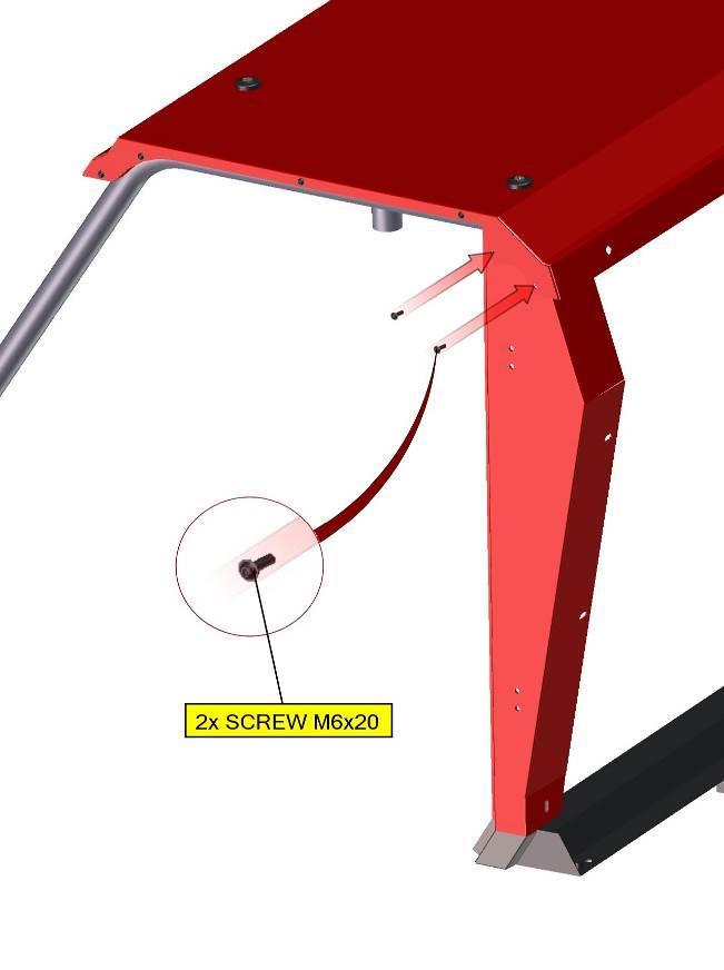
22 Place the front ledge holders onto the front bottom part of the roller cage on both sides. Fix the holders with the ledge to roller cage by screws, washers, nuts and nut covers. Do not tight these screws hard yet! 22
.")
23 The straight side of the door stop pin holder has to be orientated on to the top (with red outline). 23

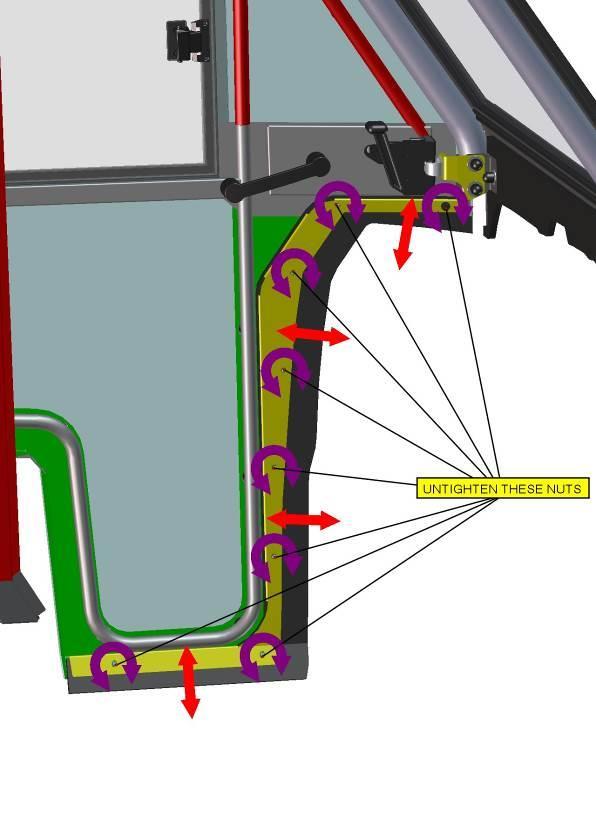
24 Loosen the nuts in red circles. Place the front window onto the roller cage and push it under the roof. Front glass with sealing has to be lying on the front ledge welded. 24

25 Cut the thread M8 in the original hole (in red circle) on the upper front corner reinforcement on both sides. 25

26 Place the front upper glass holders (left and right) onto the correct position. Fix these holders with glass by screws, washers, nuts and nut covers. Fix the holders with the UTV s roller cage reinforcements by washers, screws and nut covers. Tight the front glass holders screws with attention, if you tight these screws too hard the front glass may by crackle. 26

27 Detail view onto the fixed front upper glass holder. 27

28 DOOR LEFT: INSTALLATION OF THE RIGHT DOOR IS IDENTICAL WITH THE INSTALLATION OF THE LEFT DOOR. Place the hinges onto the metal door base. 28

29 Fix the hinges with the metal door base by screws, washers, nut and nut covers. POLARIS RANGER 29


30 Detail view on fixed hinges from outside and from inside. 30

31 You have to lubricate the hinge s pins and place the door onto the hinges. POLARIS RANGER 31
 has to be simillar (from 4mm to 6mm).")
32 Adjust the door to make no gapes betwen the front roller cage, the UTV s body and the door sealing. Distance between the door, the roof and the door metal base (yellow line) has to be simillar (from 4mm to 6mm). 32 Adjust the pin of door stop holder.

33 If you close the door slowely and holder has been adjusted correctly, you can hear clear metallic click. If you have problems with adjusting the pin holders, you can adjust the door hinges again to better position. 33 Now loosen the front bottom ledge nuts and adjust the door ledge epdm (red arrows).
34 34


35 Settle EPDM of front bottom lath so that whole front bottom edge will fit tightly to the profile of dashboard. We recommend to cutting front edge of EPDM under the angle 35 for better sticking to the frame. 35
36 ELECTROINSTALLATION WASHER SYSTEM: Overall wiring diagram (wiper, washer, heating). 36


37 Accessories for mounting the bottle washer. Bottle washer has to be placed below the driver seat near to the battery. Electrical wiring for the washer is kept in a harness. 37


38 Connect the harness branch no.: 1 with washer pump. (detail) POLARIS RANGER Uninstall the plastic cover original screw. 38


39 Dismount the plastic cover on the cabin floor of the UTV s body. POLARIS RANGER Strech the harness throught the UTV s floor tunnel. 39


40 Pull out the plastic rivet from the plastic cover. Dismount the plastic cover of the left front wheel. Lead the harness from the floor tunnel to the front battery box as the arrows show at the picture. 40

41 Next step of the leading. 41


42 Pull out the plastic rivet from the central dashboard panel. Uninstall the central dashboard panel. 42 Connect the harness branch no.:2 with main UTV s switch (In red rectangle).


43 Detail of connection. 43 Cut the rectangle hole into the central dashboard panel.

.")
44 Strech the harness branch no.:3 trought the hole for switch and connect with switch wiper/washer (in red rectangle). 44 Detail of connection.


45 View from the battery box. 45 Drill hole φ12 onto the dashboard near the right front roller cage.


46 Continue with the wiring inside the dashboard and lead it up on the left side of the roller cage to the wiper motor. Runs along the original wiring harness in the dashboard. 46 Stretch the harness branch no.:4 through the hole.

47 47 Lead the harnes branch no.:4 around the right front part of the roller cage and around roof


48 Allow the screw in the wiper motor cover and take the cover out. Connect the harness branch no.:4 with the wiper motor. 48 Hose connection to washer jet in the roof.


49 Fill the water to the washer tank before starting usage. 49 ELECTROINSTALLATION HEATER SYSTEM: The cabin can be supplied with 2 different types of heaters Type A and type B.


50 If in installation instructions is not specified to the which type of heater is concerned step, then the step is the same for both types. Accessories for mounting the heater system for heater type A harness heating holder air vent valve Y coupling heater heater tube for DIESEL engine tightening strap electromagnetic vent 50 screw rivets bottom part of heater holder vent switch flange Accessories for mounting the heater system for heater type B


51 harness heating holder Y coupling heater tightening strap screw rivets 51 flange for PETROL engine air vent valve heater tube for DIESEL engine Heater is designed to be inside the glove box at the dashboard. Uninstall door of the glove box from the hinge.


52 Drill 2 holes 25mm on the left side of the glove box at the dashboard. 52 Outside view from the front side. (Holes are in red circles)


53 Drill the hole mm to the upper side of glove box. 53 Insert hot water hoses and harness into the holes. Connect the hoses with the pipes of the heater. (Heater type A )
.")

54 Connect the harness branch no.: 3 with heater (detail of connection). (Heater type A ) 54 Connect the harness of heater with switcher in heater cover. (Heater type A )


")
55 Pull out the plastic button from switch. Uninstall the nut from switch and pull the switch out from the cover. View on to the switch assembly. Connect the heater harness with switch. 55 View on to connected harness. Install switcher back into the heater cover. Connect the harness branch no.: 4 to the electric vent switch on the heater cover. (Heater type A ) When the swith is backlit, electric vent is turn off and hot water from engine cooling don t run in heater.
.")
 56 Insert the heater holder onto the dashboard,")
56 Place the bottom part of heater holder onto the position (outlines in red). Insert the heater to the glove box (left side first). (Heater type A ) 56 Insert the heater holder onto the dashboard, drill 3 holes φ8mm, insert screw rivet and tighten. (Heater type A )
.")

57 Fix the heater cover with heater holder by 4 x screw M5x20 (2 upper screws are in red circles). (Heater type A ) 57 For placing of the electric vent cut the water tube connected to the upper pipe of the heater and insert the electric vent.
 POLARIS RANGER Connect the harness branch no.: 2 with the vent. Detail of connection.")
58 Fix the water tube with vent by tightening strap. The vent must by in same orientation like in picture. (Heater type A ) POLARIS RANGER Connect the harness branch no.: 2 with the vent. Detail of connection. (Heater type A ) 58 Instructions for heater type B

 59 Connect the harness branch no.")
59 Connect the water hose with electric vent and fix these by tightening straps. (Heater type B ) Connect the water hose with water tube and fix these by tightening straps. (Heater type B ) 59 Connect the harness branch no.:1 with the heater harness (detail view.) (Heater type B )


60 Place the heater holder on position and make marks according with holes. (Heater type B ) 60 Drill 4 holes φ8mm in dashboard according with holes on the heater holder, insert screw rivet and tighten.

61 (Heater type B ) Connect the harness branch no.: 1 with main switch of the UTV. (Heater type A ) Connect the harness branch no.: 2 with main switch of the UTV. (Heater type B ) 61 Cut the hose without the electromagnetic vent and insert tightening straps onto the hose.


62 Insert the air vent valve (in red circle) into the both end of the hose and tight the straps hard. (For both types of heater) Lead the water hoses from the battery box to the floor tunnel. (For both types of heater) 62 Detail view on the right rear corner of the front battery box.


63 View onto the right bottom part of the UTV s. (Near right front wheel). 63 Water hoses in the floor tunnel.
 from tunnel to the UTV s engine.")
64 Cut the water hose (red line) with air vent valve to correct length. Lead the water hose with electromagnetic vent (orange arrow) from tunnel to the UTV s engine. 64 Insert the tightening straps and T coupling into the short water hose.
 into the original water hose and tight the straps very hard.")
.")
65 Secure the original left water hose (run water back to engine) on both sides using lockable pliers or clamps to avoid lose of cooling liquid. Cut the original water hose and insert the tightening straps on both ends. Insert the Y coupling (red ellipse) into the original water hose and tight the straps very hard. Take out the pliers from the original water hose. NEXT FEW STEPS ARE FOR INSTALLATION ON PETROL ENGINE Uninstall the thermostat flange from the engine and connect that with flange (included with cabin). You may be have to disconnect the original water hose from the thermostat flange before uninstallation. 65 You have to place the included flange rubber side (red line) on engine. (For detail of flange see pages No.:51, 52)


66 Place the original flange with included flange back to position on engine and fix these by 2 screws M6x50 and washers. Insert tightening strap on the water hose and connect the hose with tube on the flange and tighten the strap very hard. You can install back the original hose to the original flange. 66 NEXT FEW STEPS ARE FOR INSTALLATION ON DIESEL ENGINE Take out the seat from the UTV and uninstall the original screw (in red circle) from the UTV s engine. (Detail view on next page)

67 Detail view Drop the screw glue on heater tube and insert the heater tube instead of the original screw and tighten very hard. Insert the tightening strap on the heater hose and insert hose on the heater tube. Tighten the strap very hard. 67 SEE NEXT PAGE
68 Important notice: 1. Before the first turning on the hot water heater it is necessary to check the tightness of the cooling circuit of the hot water heater. 2. If necessary add more cooling liquid to the cooling circuit. 3. Turn UTV s engine on and open the air vent valve. 4. Turn heater on and wait for the maximum temperature. When the cooling liquid starts to leak from the air vent valve close the valve. Turn off heater and add more cooling liquid to the cooling circuit if need it. In cab units where you are installing the glove compartment heater provided in the standard DFK Cab Kit, it is important to check the coolant level regularly at least 4-5 times during the first several days of operation and fill as necessary until the coolant level has stabilized. The heater will draw and retain coolant, sometimes at the expense of coolant to the engine. This can cause engine overheating if not managed properly. 68
INSTALLATION INSTRUCTIONS
 INSTALLATION INSTRUCTIONS POLARIS RANGER In case of facing any problems, please dial +420 572 520 063, 9 or email at dfk@dfk.cz. SAFETY INSTRUCTIONS Warning: Failure to heed all safety and operating instructions
INSTALLATION INSTRUCTIONS POLARIS RANGER 400 H.O.
 INSTALLATION INSTRUCTIONS POLARIS RANGER 400 H.O.. SAFETY INSTRUCTIONS Warning: Failure to heed all safety and operating instructions and warnings regarding use of this product can result in serious bodily
INSTALLATION INSTRUCTIONS HONDA PIONEER (2014)
") INSTALLATION INSTRUCTIONS. SAFETY INSTRUCTIONS Warning: Failure to heed all safety and operating instructions and warnings regarding use of this product can result in serious bodily injury. READ PROPERLY
INSTALLATION INSTRUCTIONS. SAFETY INSTRUCTIONS Warning: Failure to heed all safety and operating instructions and warnings regarding use of this product can result in serious bodily injury. READ PROPERLY
INSTALLATION INSTRUCTIONS JOHN DEERE XUV 625I
 INSTALLATION INSTRUCTIONS JOHN DEERE. SAFETY INSTRUCTIONS Warning: Failure to heed all safety and operating instructions and warnings regarding use of this product can result in serious bodily injury.
INSTALLATION INSTRUCTIONS POLARIS GENERAL 1000 EPS
 INSTALLATION INSTRUCTIONS POLARIS. SAFETY INSTRUCTIONS Warning: Failure to heed all safety and operating instructions and warnings regarding use of this product can result in serious bodily injury. READ
DOOR SET INSTALLATION INSTRUCTIONS POLARIS RANGER 900XP
 DOOR SET INSTALLATION INSTRUCTIONS POLARIS RANGER 900XP. SAFETY INSTRUCTIONS POLARIS RANGER 900XP DOOR SET Warning: Failure to heed all safety and operating instructions and warnings regarding use of this
INSTALLATION INSTRUCTIONS KYMCO 500I, 700I SE
 INSTALLATION INSTRUCTIONS KYMCO 500I, 700I SE. TOOLS NEEDED Not included Ratchet handle Socket beg 13 mm Hex key 5 and 6mm (0,51 in) 2 Metric wrench 13mm Screwdriver philips Utility knife Isolating tape
Heater for BRP Commander. Caution: Before using this product, read this manual and follow all safety instructions. Owner s Manual
 Owner s Manual Model: Can Am Commander Heater for BRP Commander Caution: Before using this product, read this manual and follow all safety instructions. Safety Instructions Kit Contents Tool Requirement
INSTALLATION & OWNER S MANUAL
 Rev. A, p. 1 of 8 INSTALLATION & OWNER S MANUAL HONDA PIONEER 700-2 AND 700-4 HEATER INSTALLATION p/n: 9PH20S64 The contents of this envelope are the property of the owner. Be sure to leave with the owner
Roof Console with Heater, Switches, Dome light & Optional Radio kit
 Owner s Manual Fits cab Models: -Landini 1-25 -Kioti CK20S, CK20S HST -McCormick X10.25 -Bobcat CT122 Caution: Before using this product, read this manual and follow all safety instruction Roof Console
JOHN DEERE GATOR HPX/XUV 2 PASSENGER HEATER INSTALLATION INSTRUCTIONS (p/n: 9PH20S30)
") P. 1 of 12 JOHN DEERE GATOR HPX/XUV 2 PASSENGER HEATER INSTALLATION INSTRUCTIONS (p/n: 9PH20S30) Item: Qty: Description: 1 2 1 x 1 x 5/8 Tee Fitting 2 2 Plastic Snap-in Hose Grommet 3 4 1-1/2" Hose Clamps
P. 1 of 12 JOHN DEERE GATOR HPX/XUV 2 PASSENGER HEATER INSTALLATION INSTRUCTIONS (p/n: 9PH20S30) Item: Qty: Description: 1 2 1 x 1 x 5/8 Tee Fitting 2 2 Plastic Snap-in Hose Grommet 3 4 1-1/2" Hose Clamps
Installation Instructions Part No , Part No Part No
 Torsion-Flex Motor mount for PSC motors and Rigid-Mount for ECM motors Replacement Kit Cancels: New Installation Instructions Part No. 327752-401, Part No. 327753-401 Part No. 327754-401 IIK-310A-45-11
KIT CONTENTS Ref Qty Part Description Part Number
 CAB HEATER KIT P/N 2879967 APPLICATION RANGER 570 AND RANGER 570 CREW BEFORE YOU BEGIN Read these instructions thoroughly and make sure all parts and tools are accounted for. Please retain these installation
2 Drawer Vehicle Storage System
 2 Drawer Vehicle Storage System Part No 51000 Installation: Includes: Mounting Kit: 4 x bolts 4 x washers 4 x locking nuts 1 Remove right hand side top section by undoing the 10 retaining screws and set
Heater with Air Conditioning. E-Series Ford Aeromaster
 Service Guide Heater with Air Conditioning E-Series Ford Aeromaster Contents Blower Motor...2 Plenum Removal...3 Control Module...6 Servo Motors...8 Coolant Valve and Servo Motor...8 Evaporator Recirculation
INTRODUCTION. NOTE: Read the entire instruction manual before starting the installation. FIRE, EXPLOSION, ELECTRICAL SHOCK HAZARD
 Installation Instructions NOTE: Read the entire instruction manual before starting the installation. SAFETY CONSIDERATIONS Improper installation, adjustment, alteration, service, maintenance, or use can
English BT3600
 www.blackanddecker.com 3 English BT3600 FIG. 1 FIG. 2 150mm BENCH GRINDER BT3600 GENERAL SAFETY RULES WARNING: Read all instructions. Failure to follow all instructions listed below may result in electric
20-GALLON MOBILE PARTS WASHER OWNER S MANUAL
 20-GALLON MOBILE PARTS WASHER OWNER S MANUAL WARNING: Read carefully and understand all INSTRUCTIONS before operating. Failure to follow the safety rules and other basic safety precautions may result in
Damp Locations Wall & Ceiling Mount BEFORE YOU BEGIN
 INSTALLATION AND ASSEMBLY INSTRUCTIONS LXLW LED SERIES Damp Locations Wall & Ceiling Mount SAVE THESE INSTRUCTIONS AND DELIVER TO OWNER AFTER INSTALLATION BEFORE YOU BEGIN Read these instructions completely
This site is based on a but applies to all 1971-on Saab 99 and Saab 900.
 by Mark Jeter updated: December 8, 2004 originally web-published June 27, 2001 This document shows how the original waterpump in a Saab "B" engine can be eliminated and replaced with a reliable, efficient
5.0 cu ft Electric Concrete Mixer
 Save This Manual for Future Reference 5.0 cu ft Electric Concrete Mixer Operator s Manual MODEL NUMBER YM0146 SERIAL NUMBER PURCHASE DATE Both model number and serial number may be found on the main label
Quick Fix. Service Guide. Washers, Dryers, and Refrigerators
 Quick Fix Service Guide, Dryers, and Refrigerators Quick Fix tips provide a ready reference to the most frequently occurring repairs and adjustments that service technicians are likely to encounter. This
PRELIMINARY INSTALLATION. Operation & Service Manual. Carrier Transicold Europe 03/09/07 Viento - Installation/Rev- #1/56
 INSTALLATION Carrier Transicold Europe 03/09/07 Viento - Installation/Rev- #1/56 INSTALLATION Table of content Introduction...4 Preparation before installation...5 Vehicle partition... 6 Box preparation...7
SERVICING INFORMATION
 SERVICING INFORMATION OPTIKINETICS SOLAR 250 (Early Type) M.Ginda 06/03/08 1 Servicing the Solar 250 effects projector. This is a short guide on how to service the main component parts of the projector.
Heat Exchanger Block Replacement Instructions
 Series 1-4 Gas-fired water boiler Heat Exchanger Block Replacement Instructions Ultra-80 S1-4 Heat Exchanger Block Replacement Kit, Part No. 383-500-773 Ultra-105 S1-4 Heat Exchanger Block Replacement
INSTALLATION INSTRUCTIONS
 INSTALLATION INSTRUCTIONS Accessory Application Publication No. HEATER KIT P/N 0SE01-HL3-102 (SXS700M2/M4) P/N 0SE01-HL3-103 (SXS700M2D/M4D) SXS700M2/M2D/M4/M4D MII 14607-15172 Issue Date REVISED: June
MOUNTING INSTRUCTIONS
 A-12093 JDX 2014 HEATER KIT With Gas Engine Connection Fittings 2014 and Newer ROPS Cabs A-12098 (Kit A-12092, Diesel Engine Connection Fittings are sold separately for diesel models) 12VDC, 2-Speed, 15,000
JOHN DEERE X465, X475, X485, X495, X575, X585
 JOHN DEERE X465, X475, X485, X495, X575, X585 and X595 X700 SERIES (X700, X720, X720se, X724, X728, X728se, X729, X740, X744, X748, X748se, X749) CAB MOUNTING INSTRUCTIONS A-11271 Manufactured by: BOX
PS /2 Inch Angle Grinder Assembly & Operating Instructions READ ALL INSTRUCTIONS AND WARNINGS BEFORE USING THIS PRODUCT.
 PS07214 4 1/2 Inch Angle Grinder Assembly & Operating Instructions READ ALL INSTRUCTIONS AND WARNINGS BEFORE USING THIS PRODUCT. This manual provides important information on proper operation & maintenance.
OWNERS MANUAL. To Order Parts Call SPEED AIR MOVER
 3 SPEED AIR MOVER OWNERS MANUAL IMPORTANT: READ OWNERS MANUAL CAREFULLY Please fill out and return your warranty card! MODEL # STR3SPD. REV 01 (6 12) TABLE OF CONTENTS Safety Precautions 3 Machine Operation
INSTALLATION INSTRUCTIONS
 Accessory Application Publication No. INSTALLATION INSTRUCTIONS HEATER KIT P/N 0SE01-HL3-101 SXS700M4/M2 Honda Dealer: Please give a copy of these instructions to your customer. PARTS LIST REPAIR KIT (P/N
specializing in AIR CONDITIONING, PARTS AND SYSTEMS for your classic hi l PERFECT FIT SERIES IN-DASH HEAT/ COOL/ DEFROST FORD TRUCK
 specializing in AIR CONDITIONING, PARTS AND SYSTEMS for your classic hi l PERFECT FIT SERIES IN-DASH HEAT/ COOL/ DEFROST 1967-72 FORD TRUCK CONTROL & OPERATING INSTRUCTIONS The controls on your new Perfect
Floor Standing Bath Shower Mixer. Fitting instructions. Please keep these instructions for future reference and request of replacement parts.
 Floor Standing Bath Shower Mixer Fitting instructions Please keep these instructions for future reference and request of replacement parts. We have taken great care to ensure that this product reaches
Installation. Leveling
 Your refrigerator was packed carefully for shipment. Remove and discard shelf packaging and tape. Do not remove the serial plate. Location Do not install refrigerator near oven, radiator or other heat
A HEATER KIT With Diesel Engine Connection Fittings
 A-12142 HEATER KIT With Diesel Engine Connection Fittings Figure 1 (General Layout and Parts I.D.) Page 1 of 6 Read these instructions and identify all components. Please retain these instructions for
PERFECT FIT SERIES IN-DASH HEAT/ COOL/ DEFROST CHEVROLET NOVA
 specializing in AIR CONDITIONING, PARTS AND SYSTEMS for your classic PERFECT FIT SERIES IN-DASH HEAT/ COOL/ DEFROST 1966-67 CHEVROLET NOVA CONTROL & OPERATING INSTRUCTIONS The controls on your new Perfect
F A B G L A S S A N D M I R R O R
 Frameless Panel MSD1 FAB GLASS AND MIRROR www.fabglassandmirror.com Call: +1 888-474-2221 Office Timing: 8:30-18:00 EST Fax: (614)-334-4919 info@fabglassandmirror.com INSTALLATION INSTRUCTION SHOWER ENCLOSURE
PARTS & ACCESSORIES INSTALLATION AND SAFETY INSTRCUTIONS ITEM NO.:60006PC SAFETY PRECAUTION. Canopy. Downrod. Housing. Blade. Transmitter CR2032/3V
 L I G H T I N G INSTALLATION AND SAFETY INSTRCUTIONS ITEM NO.:000PC SAFETY PRECAUTION PARTS & ACCESSORIES Canopy Downrod Housing IMPORTANT : PLEASE READ BEFORE INSTALLATION.. Do not connect this remote
Cable Drum Machine. Operation Manual 110ES SERIES. Cleans 1 1/4" to 3" lines up to 25'
 Cable Drum Machine Operation Manual 110ES SERIES Cleans 1 1/4" to 3" lines up to 25' Used For: Sinks, Showers &Tub Drains WARNING - Read All Instructions, When Using Electric Tools, Basic Safety Precautions
ZD-985 Desoldering Station
 ZD-985 Desoldering Station 2 Contents Contents... 3 Unpacking and Setting Up Your ZD-985 Desoldering Station... 4 Setting Up the Unit... 5 Auto Tip Saver Function... 8 Tips and Techniques... 8 Alloy Melt
ENRGY CURB APPLICATION GUIDE FOR TPO ROOFING SYSTEMS
 1. Introduction The ENRGY Curb mounting system is a lightweight, nonpenetrating, roof-integrated, photovoltaic (PV) mounting system designed to maintain roof integrity and maximize power density. This
HOT WASHER MODEL NO: KING150
 WARNING: Do not use the hot washer without reading this manual HOT WASHER MODEL NO: KING150 PART NO: 7320175 OPERATION & MAINTENANCE INSTRUCTIONS LS1215 INTRODUCTION Thank you for purchasing this CLARKE
WARNING: ELECTRICAL GROUNDING INSTRUCTIONS
 BK AND BKT BLOWER ACCESSORY INSTALLATION INSTRUCTIONS Model BK Manually led Blower Model BKT Thermostatically led Blower WARNING: ELECTRICAL GROUNDING INSTRUCTIONS This appliance is equipped with a three-prong
Installation, Operation and Maintenance Instructions for ThermaFlex Gasketed Plate Heat Exchangers
 OM010 Installation, Operation and Maintenance Instructions for ThermaFlex Gasketed Plate Heat Exchangers The operating and maintenance instructions contained within this package are for ThermaFlex gasketed
NISSAN FRONTIER INSTALLATION INSTRUCTIONS
 NISSAN FRONTIER INSTALLATION INSTRUCTIONS TABLE OF CONTENTS RLN2-1511 LEER, A Division of Truck Accessory Group, LLC 28858 Ventura Dr. Elkhart, IN 46517 Technical Support: (866) 419-4932 For Sales Inquires
BlueHeat AirTop 2000 Heater
 BlueHeat AirTop 000 Heater Air Heater Installation Manual Ford E-Series 6.0L Diesel Beginning Model Year: 006 Special instructions for these models Part locations may differ slightly dependent on the vehicle
Heating and ventilation system,
 Page 1 of 24 87-151 Heating and ventilation system, servicing Instrument panel air outlets and air guide ducts CAUTION! Before working on the electrical system: Obtain security code for anti-theft radio.
INSTRUCTION MANUAL MODEL: 690E
 1 INSTRUCTION MANUAL ALEKO Drywall Sander MODEL: 690E READ THROUGH CAREFULLY AND UNDERSTAND THESE INSTRUCTIONS BEFORE USE Visit our web site for more great products, parts and accessories: 2 3 4 5 6 Caution!
Please read the following installation instructions first after purchasing this product or transporting it to another location.
 9 Installation Overview Please read the following installation instructions first after purchasing this product or transporting it to another location. 1 Unpacking your refrigerator 2 Choosing the proper
PERFECT FIT IN-DASH HEAT/ COOL/ DEFROST FORD PICKUP
 specializing in AIR CONDITIONING, PARTS AND SYSTEMS for your classic vehicle PERFECT FIT IN-DASH HEAT/ COOL/ DEFROST 1960-66 FORD PICKUP CONTROL & OPERATING INSTRUCTIONS The controls on your new Perfect
P.O.D. Pressure On Demand
 P.O.D. Pressure On Demand OWNERS MANUAL & INSTRUCTIONS Please! Read all these instruction carefully before use and save these instructions for future reference. SAFETY INSTRUCTIONS NEVER open the Pressure
MOUNTING INSTRUCTIONS
 John Deere HPX and XUV Heater Kit 4-14916 MOUNTING INSTRUCTIONS With replacement parts drawing BOX 70 LITCHFIELD, MINNESOTA 55355-0070 (320) 693-3221 Fax: (320) 693-7252 Visit our web site at: www.800cabline.com
OPERATING & SERVICE PARTS MANUAL HDS-215 COMBINATION SHRINK SYSTEM
 OPERATING & SERVICE PARTS MANUAL HDS-215 COMBINATION SHRINK SYSTEM FOR HOT KNIFE AND IMPULSE MACHINES READ ALL INSTRUCTIONS CAREFULLY BEFORE OPERATING EQUIPMENT TABLE OF CONTENTS Electrical Requirements
DUST EXTRACTOR INSTRUCTION MANUAL. 550W (3/4 HP) INDUCTION MOTOR 1850W AUTOMATIC POWER OUTLET 65L COLLECTION BAG ø100mm X 2.
 INDUCTION MOTOR 1850W AUTOMATIC POWER OUTLET 65L COLLECTION BAG ø100mm X 2.") KNOW YOUR PRODUCT DUST EXTRACTOR 550W (3/4 HP) INDUCTION MOTOR 1850W AUTOMATIC POWER OUTLET 65L COLLECTION BAG ø100mm X 2.5M SUCTION HOSE INSTRUCTION MANUAL WARNING: Read all safety warnings and all instructions.
KNOW YOUR PRODUCT DUST EXTRACTOR 550W (3/4 HP) INDUCTION MOTOR 1850W AUTOMATIC POWER OUTLET 65L COLLECTION BAG ø100mm X 2.5M SUCTION HOSE INSTRUCTION MANUAL WARNING: Read all safety warnings and all instructions.
BK AND BKT BLOWER ACCESSORY INSTALLATION INSTRUCTIONS
 BK AND BKT BLOWER ACCESSORY INSTALLATION INSTRUCTIONS MODEL BK MANUALLY CONTROLLED BLOWER MODEL BKT THERMOSTATICALLY CONTROLLED BLOWER WARNING: ELECTRICAL GROUNDING INSTRUCTIONS This appliance is equipped
Scrubber User Manual
 Scrubber User Manual AS430C VIPER NORTH AMERICA [866] 418-4737 [866] 41-VIPER VF90031-US Rev.01 TABLE OF CONTENTS USER MANUAL INTRODUCTION... 2 CONTENTS............................. 2 PURPOSE.............................
EXPOSED BATH SHOWER MIXER INSTRUCTION MANUAL W INST 300. Please note: Tap heads shown is for illustration purposes only.
 EXPOSED BATH SHOWER MIXER INSTRUCTION MANUAL W INST 300 Please note: Tap heads shown is for illustration purposes only. CONTENTS GUARANTEE GENERAL SAFETY INSTRUCTIONS PARTS SUPPLIED HOW TO INSTALL AFTER
installation and operation manual for Hunter Ceiling Fans
 For Your Records and Warranty Assistance Model Name: Catalog/Model No.: Serial No.: Date Purchased: Where Purchased: For reference also attach your receipt or a copy of your receipt to the manual. installation
Product Support Bulletin
 MODEL: SUBJECT: CONVENTIONAL, W/ C7 CAT ENGINE WEBASTO TSL-17 HEATER Body DATE: APRIL 13, 2004 INDEX: 6 PAGE: 1 OF 16 Before you start this procedure, perform Freightliner Service Bulletin #20-7 first.
TOOLS REQUIRED: Crimping tool A/C Recovery Unit Wrench set up to 1 ¼ 4 Hole saw
 INSTALL INSTRUCTIONS PT-A-401 HVAC UNIT for 2003-2018 CHEVROLET/GMC VAN (For 2007 ALL WHITE Prisoner Transport Inserts ONLY) Not Recommended for diesel engine application because of lack of space needed
BATHROOM FURNITURE FITTING GUIDE
 SE30566C0 BATHROOM FURNITURE FITTING GUIDE Please spend 5 minutes reading this section before commencing with the installation of your new furniture. 1. Should any of your items have a defect, please do
MODEL 1308-C & 1308-N
 Grand Rapids, Michigan, U.S.A. 49504-5298 USER S OPERATING AND INSTRUCTION MANUAL MODEL 1308-C & 1308-N HEAT SEALER 1308S20000CV1 INDEX Section Description Document No. Page No. DESCRIPTION/SPECIFICATIONS
BC BRONCOS AIR CONDITIONING UNIT
 BC BRONCOS AIR CONDITIONING UNIT CAUTION If you are not familiar with the principals of air conditioning, have an authorized air conditioning technician evacuate and charge the system. Serious damage to
Installation Instructions
 Suzuki Samurai Coolant and Water Hose Kit (SKU# SER-CHK) Installation Instructions SER-HHCK SER-WPI SER-ROP CAUTION: Safety glasses should be worn at all times when working with vehicles and related tools
50 Disassembly and assembly Cab and its attachments
 When adjustment is needed after performing check in step 8; 3) Close front window assembly (1). 4) Loosen locknuts (26) of right and left rubber stoppers (24) and move the stoppers backward so that front
HANDLING INSTRUCTIONS for DISPENSA VVS-x
 02/2012 Top runner (with stop point) Top damper Stop point Support frame Trays or baskets Pull-out components: Top runner Support frame Trays or baskets Front panel connector Bottom runner Top damper (optional)
Safety. Rinse Kit for Multi-Pro 1200 and 1250 Turf Sprayers Model No Safety and Instructional Decals. Installation Instructions
 Rinse Kit for Multi-Pro 1200 and 1250 Turf Sprayers Model No. 106-4842 Form No. 3353-529 Rev B Installation Instructions Note: Determine the left and right sides of the machine from the normal operating
ENCLOSED PARTS WASHER WITH HEATING SYSTEM ---EPW160-H
 Please read and save these instructions. Read through this owner s manual carefully before using product. Protect yourself and others by observing all safety information, warnings, and cautions. Failure
NEPTUNE Steam Room Installation Instructions
 NEPTUNE Steam Room Installation Instructions IMPORTANT Please read carefully the following instructions before installing your shower cabin. If you have any questions on this shower cabin installation
hp Dust Collector With Vacuum Attachment
 Please dispose of packaging for the product in a responsible manner. It is suitable for recycling. Help to protect the environment, take the packaging to the local amenity tip and place into the appropriate
D O U B L E A U G E R M O R TA R M I X E R OWNER S MANUAL
 D O U B L E A U G E R M O R TA R M I X E R OWNER S MANUAL WARNING: Read carefully and understand all INSTRUCTIONS before operating. Failure to follow the safety rules and other basic safety precautions
PARTS & ACCESSORIES INSTALLATION AND SAFETY INSTRCUTIONS ITEM NO.:60010BZGTGLD SAFETY PRECAUTION. Canopy. Downrod. Housing. Transmitter CR2032/3V
 L I G H T I N G INSTALLATION AND SAFETY INSTRCUTIONS ITEM NO.:000BZGTGLD SAFETY PRECAUTION PARTS & ACCESSORIES Canopy Downrod Housing WARNING To make sure power is off before attempting installation. WARNING
SCC 101 G Valid as of G11SE0404 up to G11SE... SCC 101 G
 Gas unit Voltage 1NAC 230V 50-60Hz 1 1 Control panel 2 2 Electrical installation 3 3 Clima Plus 4 4 Steam generator, Bypass 5 5 Hot air heating 6 6 Motor and fan wheel 7 7 Interior cabinet 8 8 Door 9 9
Unpacking and removing shipping bolts. Connecting the drain line Leveling the washer Connecting to the power supply
 11 INSTALLATION Installation Overview Choosing the proper location Unpacking and removing shipping bolts Connecting the water line Connecting the drain line Leveling the washer Connecting to the power
BMW E36 Thermostat Removal And Coolant Flush
 BMW E36 Thermostat Removal And Coolant Flush Disclaimer: The cooling system is critical to the proper operation of your car. Failure to properly install all of the components of the cooling system could
FFP S700 SERIES. Pull-Out Spray Faucet. Installation guide
 FFP S700 SERIES Pull-Out Spray Faucet Installation guide G 1782 G 1748.XX G 29016 G 1156 G R0239.XX G 13396.XX G R0637 G R1664 G 1636 G 1463 TECHNICAL DATA Minimum working pressure 0,5 bar Maximum working
IMPORTANT NOTICES INSTALLATION INSTRUCTIONS KAWASAKI MULE SX FULL VENT WINDSHIELD (WITH FOLDING UNDER HOOD STORAGE ACCESS) PART #
 PART #") INSTALLATION INSTRUCTIONS KAWASAKI MULE SX FULL VENT WINDSHIELD (WITH FOLDING UNDER HOOD STORAGE ACCESS) PART # 77-8600 IMPORTANT NOTICES READ AND UNDERSTAND THESE INSTRUCTIONS COMPLETELY BEFORE INSTALLATION
INSTALLATION INSTRUCTIONS KAWASAKI MULE SX FULL VENT WINDSHIELD (WITH FOLDING UNDER HOOD STORAGE ACCESS) PART # 77-8600 IMPORTANT NOTICES READ AND UNDERSTAND THESE INSTRUCTIONS COMPLETELY BEFORE INSTALLATION
36" Drum Plug Aerator OWNER S MANUAL
 36" Drum Plug Aerator OWNER S MANUAL WARNING: Read carefully and understand all ASSEMBLY AND OPERATION INSTRUCTIONS before operating. Failure to follow the safety rules and other basic safety precautions
DUAL FUNCTION MAGNETIC ROWING MACHINE
 DUAL FUNCTION MAGNETIC ROWING MACHINE SF-RW5622 USER MANUAL IMPORTANT! Please retain owner s manual for maintenance and adjustment instructions. Your satisfaction is very important to us, PLEASE DO NOT
Contents. For your safety About your product Installing your appliance Using your appliance Care & cleaning...
 USER GUIDE TF5517S Contents For your safety..................................................... 1 About your product.................................................. 3 Installing your appliance...............................................
Rycroft Supapac Plate Heat Exchangers
 Rycroft Supapac Plate Heat Exchangers Installation Operation & Maintenance Manual Ormandy Rycroft Duncombe Road Bradford BD8 9TB England TEL +44 (0)1274 490911 FAX +44 (0)1274 498580 www.rycroft.com 1.
Accessories. Safety Warnings. Table of Contents
 Table of Contents Accessories...1 Safety Warnings...1 Work Area...2 Electrical Safety...2 Personal Safety...2 Power Tool Use and Care...3 Service...3 Hammer Safety Warnings...3 Usage...4 Changing Tools...4
INSTALLATION INSTRUCTIONS
 INSTALLATION INSTRUCTIONS INSTALLATION REQUIREMENTS Tools and Parts Gather required tools and parts before starting installation. Tools needed: Optional tools: Flashlight Options: Bucket Pedestal: You
Before using your machine, you must familiarize yourself with all of its components.
 USE AND MAINTENANCE MANUAL FOR THE FOAMTEC 1800 NOTE: As with all electrical equipment, care and attention must be exercised at all times during its use, in addition to ensure that routine and preventative
PERFECT FIT IN-DASH HEAT/ COOL/ DEFROST 1968 CHEVROLET IMPALA
 specializing in AIR CONDITIONING, PARTS AND SYSTEMS for your classic vehicle PERFECT FIT IN-DASH HEAT/ COOL/ DEFROST 1968 CHEVROLET IMPALA CONTROL & OPERATING INSTRUCTIONS The controls on your new Perfect
Industrivej 3-9 DK 9460 Brovst KEF-MOTOR A/S. Fax Instruction Manual PSD 200 Industrial Grinders
 KEF-MOTOR A/S Industrivej 3-9 DK 9460 Brovst Tlf. +45 9823 6088 Fax. +45 9823 6144 1. Instruction Manual PSD 200 Industrial Grinders EU declaration of conformity KEF-MOTOR A/S Industrivej 3-9 DK-9460 Brovst
Full Size Canister Service Manual Riccar Models 1700 / 1800 Power Nozzles RPB-100 / RPB-220 / RPB-224 / RPB-250
 Full Size Canister Service Manual Riccar Models 1700 / 1800 Power Nozzles RPB-100 / RPB-220 / RPB-224 / RPB-250 Table of Contents I. General Full Size Canister Issues...2 A. Full Bag Indicator...2 1. General
Service Bulletin Trucks Date Number Page
 Mack Trucks, Inc. Allentown, PA USA (Does not apply to Mack Trucks Australia) (Supersedes SB215025 dated 03/27/07) Service Bulletin Trucks Date Number Page 11/04/08 SB215025 1(25) Cooling System Revisions
Product instruction manual Easymount Wide Format Laminators
 Product instruction manual Easymount Wide Format Laminators The Easymount has been designed to be user friendly, however we strongly recommend you take a few minutes to read through this manual to ensure
Audi-Larm Audible Alarm
 Audi-Larm Audible Alarm MAINTENANCE AND REPAIR TAL 1706 (L) Rev. 7 MSA 2017 Prnt. Spec. 10000005389(I) Mat. 10093084 Doc. 10093084 REPLACEMENT KITS AND PARTS LIST TAL 1706 (L) Rev. 7-10093084 2 Exploded
M5 BLUE BOY FIVE GALLON PAINT MIXER Owner s Manual
 M5 BLUE BOY FIVE GALLON PAINT MIXER Owner s Manual Introduction..3 Safety Precautions 4 Installation Instructions 5 Electrical Connections..7 Operating Instructions..8 Maintenance Procedures...8 Parts
Hanson LED C e i l i n g F a n
 Hanson LED C e i l i n g F a n model no. 052-8398-2 Toll-free 1-866-827-4985 IMPORTANT: For your safety please read and understand this manual before installing or operating this product. OWNER S MANUAL
Item # Modular Blast CaBinEt instructions
 Item #20464 Modular Blast CaBinEt instructions The Eastwood Modular Blast Cabinet is specifically designed with heavy-duty components and a quality powdercoated finish to provide years of trouble free
2HP MOBILE CYCLONE DUST COLLECTOR MANUAL
 HP MOBILE CYCLONE DUST COLLECTOR MANUAL MANUAL FILTER CLEANING LAGUNA TOOLS 07 Alton Parkway Irvine, California 9606 Ph: 800.3.976 www.lagunatools.com 08, Laguna Tools, Inc. LAGUNA and the LAGUNA Logo
Installation, Operation and Maintenance Instructions ThermaFlex Gasketed Plate Heat Exchanger OM010
 Installation, Operation and Maintenance Instructions ThermaFlex Gasketed Plate Heat Exchanger OM010 Calorifiers Heat Exchangers Pressurisation Units Sales Tel: 01457 835700 Sales Fax: 01457 832700 E-mail:
INSTRUCTIONS MANUAL ELECTRIC COMMERCIAL GRADE PATIO COOLER
 INSTRUCTIONS MANUAL ELECTRIC COMMERCIAL GRADE PATIO COOLER @2012.11-V1.1 Aviator X2 Page 2 of 15 Contents Instruction......3 Outline Drawing...3 Wiring Diagram......4 Installation Instructions...5-8 Checking
User s Information Manual
 48AJ,AK,AW,AY020-060 Single-Package Rooftop Gas Heating Units with COMFORTLINK Controls and Scroll Compressors User s Information Manual NOTE TO INSTALLER This manual should be left with the equipment
INSTRUCTION MANUAL TOCOA 3 SEAT SOFA-BED ITEM CODE: 11TOC3S
 Imported by Furniture Solutions (Aust) Pty Ltd 10-16 Daisy St, Revesby, NSW. 2212 www.furnituresolutions.com.au INSTRUCTION MANUAL TOCOA 3 SEAT SOFA-BED ITEM CODE: 11TOC3S Imported by Furniture Solutions
Indoor Cycling Exercise Bike
 Indoor Cycling Exercise Bike Model No. P8100 & SF-B1203 IMPORTANT! PLEASE READ THIS MANUAL CAREFULLY BEFORE USING THE BIKE. For Customer Service, please contact: support@sunnyhealthfitness.com IMPORTANT
Installation Instructions
 PAGE 1 Installation Instructions Important information about your new a/c system. Please read the following directions prior to installing this a/c system. PN: CK6772-1CHPU 1967-1972 Chevy PU A/C Kit Contact