INSTALLATION INSTRUCTIONS HONDA PIONEER (2014)
|
|
|
- Penelope Hart
- 5 years ago
- Views:
Transcription


1 INSTALLATION INSTRUCTIONS.
2 SAFETY INSTRUCTIONS Warning: Failure to heed all safety and operating instructions and warnings regarding use of this product can result in serious bodily injury. READ PROPERLY COMPLETE ASSEMBLY INSTRUCTIONS BEFORE STARTING OF ASSEMBLY Install all parts indicated in assembly instructions. Failure to fully assemble product before use could result in personal injury. Assembly of product requires use of hand or power tools. If you are not experienced in using these types of tools, have product dealer do the install for you. Some parts contain sharp edges, wear protective gloves if necessary. Always keep your assembly area clean, uncluttered and well lit. Keep visitors and children a safe distance away from the assembly area. Visitors should wear the same safety equipment described under. 2 Never operate your UTV with the cab doors open. Failure to properly latch the doors before moving the vehicle could result in serious injury. Dress for safety. DO NOT wear loose clothing, gloves, neckties or jewelry if using power tools to assemble this product. Insert all nut covers after you finish installation. Never drive your UTV with the cab front window in open position. Failure to properly latch/lock front window before driving the vehicle could result in serious injury.
3 MAINTENANCE AND CLEANING To clean polycarbonate surface use soapy water solution or other subtle means. Dirt and dust wash by gently water stream and swipe only with wet or damp means in the direction from top to bottom. The recommended frequency of cleaning of polycarbonate part is about 1 time per month or according to the actual degree of pollution. Do not use detergents that could scratch the surface plates. (abrasives, harsh fabrics, etc.) Do not use solvents or alkaline detergents or cleaners with ammonia (ammonium hydroxide). Do not remove the impurities from the surface of the razor blades or other sharp items. Do not clean cabin when the polycarbonate plates are heated by the sun. 3 Do not use the squeegee, it could be scratched surface plates. Do not clean the water current strength greater than 50 bar (WAP) The manufacturer is not responsible for scratching the surface in case of failure to comply with the above instructions. All bolted connections of cab must be by user at regular intervals checked and tightened.


4 TOOLS NEEDED Not included Ratchet handle Socket beg 13 mm Hex key 5 and 6mm (0,51 in) 4
 Uninstall the front original door from the UTV from both sides and save these for later usage.")
5 PREPARATION FOR INSTALLATION: Uninstall all additional systems from the roller cages (work lights, rear mirrors, drink holders etc.) Uninstall the front original door from the UTV from both sides and save these for later usage. 5
6 CAB PREVIEW 6


7 Washer tube ELECTROINSTALLATION-WIPER+WASHER step 1. Parts needed Included Switch wiper/washer/off Harness and washer tank Wiper harness 7
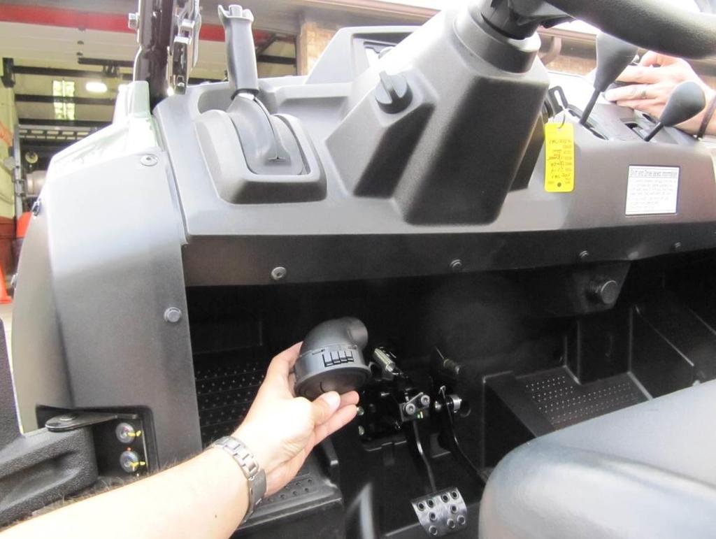
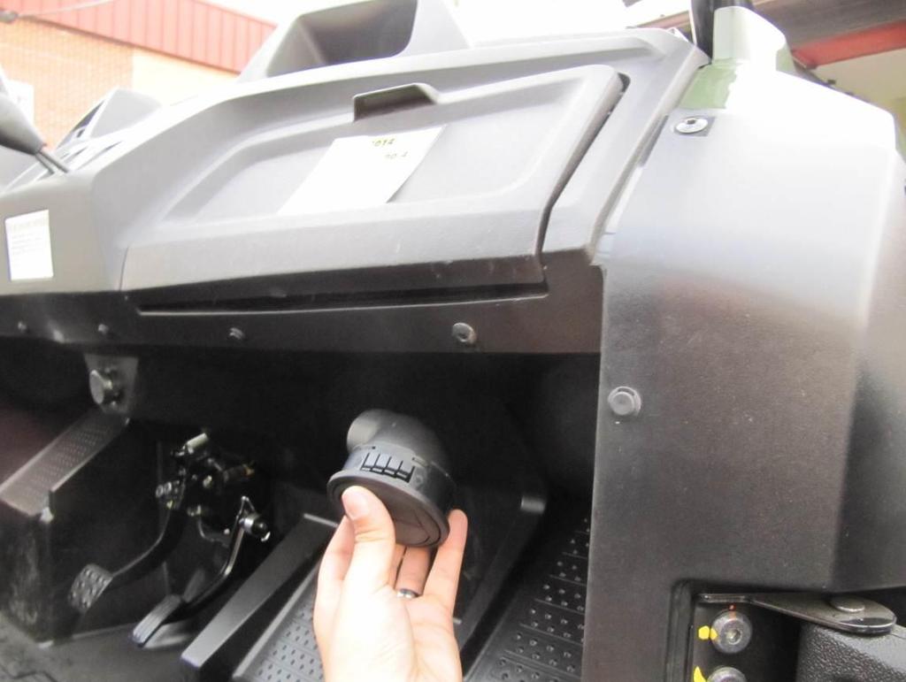
8 Find the best place for washer tank and install that by included screw, washers and nut. Loosen original fixing points and pick up the dashboard carefully. 8
9 Run with the washer harness from the washer tank to the dashboard near the driving wheel. Find the best position for the wiper/washer switch and cut rectangle hole 22,1x44,1 for switch. 9

10 10 Insert the wiper harness into the dashboard inner space and run harness branch switch to the switch hole. Stretch the harness branches for switch throught the hole from previous page.


11 Connect the branches with the switch in accordance with picture. Run the the washer hose and wiper harnes from the harnesses to the right roller cage. 11 Stretch the harness and hose throught the original gape or drill hole near the roller cage. ELECTROINSTALLATION HEATER Parts needed (included)


12 Heater with cover Bleeding valve Electric vent Tightening straps Air vent corner Air vent straight Smaller, bigger and large 12 Hot air hose AL tape Bigger Y couplings


13 Smaller Y couplings Hot water hose El. Valve switch Heater switch assembly Heater harness 13 Find the best place for air vents in dashboard.


14 It is necessary to find position without metal reinforcement under the dashboard plastic body 14
15 15

16 Make marks in correct position and cut 4 holes Ø3in (76mm) for air vents. Place the heater hoses into the front dashboard and run hose to the cuted holes. 16 Stretch the hoses throught the cuted holes and install with the air vents. Tighten the hoses with the vents by tighten straps or by Al tapes. SEE NEXT PAGES
17 17

18 Place the heater holder onto the position. 18
19 Make marks onto the frame in accordance with the heater holder s holes. Drill holes Ø11,2 into the marks centers and insert rivet nuts into the holes. 19

20 Fix the holder with the frame by screws and washers. 20

21 Find the best position for heater switch and for el. valve switch. Drill hole 21mm for el. valve switch into the dashboard. 21 SEE NEXT PAGE
 into the dashboard in")

22 Drill 1 hole ø 11,5-14mm (0,45-0,55 in) and 2 holes ø 2,5-4 mm ( 0,1-0,16 in) into the dashboard in accordance with the ventilator switch base Connect the harness branch with the heater switch like in picture.


23 Insert the heater switch into the hole from inner side and install remaining parts of the switch. Pull the harness branch for el. valve switch throught the hole from previous page (bottom picture) and connect the branch with the switch. 23


24 Run the heater harness from the switches to the heater. Install the short hose and remain of the hose to the heater tubes. Fix these hoses with the heater tubes by tightening straps and tighten these straps very hard. Insert the tightening strap onto the shorter hose and install elctromagnetic valve in same orientation like in picture. Tighten that strap very hard. 24 Install the heater hose onto the el.valve fix hose with the el. valve by tightening straps and tighten this strap very hard. Connect the harness branches with the heater.

25 Connect the harness branch with the electromagnetic vent. Insert the air vents with the heater air hoses into the holes. Connect the heater air hoses with the heater and tighten these by AL tapes. 25 SEE NEXT PAGE

26 Run the heater hoses from the heater to the front cooler space. Install the Y coupling into the engine cooling system hose and tightening by tightening straps and tighten these straps very hard. 26

27 Ininstall the seat and take out the pvc cover. 27


28 Run the heater hose with the el. valve to the engine space under the seat. Install the Y coupling into the cooling system hose and fix by tightening strap. Tighten these straps very hard. Cut the heater hose without el. valve near heater and insert the tightening straps. Install the air vent valve into the hose and fix these by straps. Tighten straps very hard. 28 Connect the wiper, washer and heater harness with the UTV electrifiacation. SEE NEXT PAGE
29 It is absolutely necessary to bleed the air out of the UTV s engine cooling system. Incomplete bleeding of cooling system can result in engine damage. If you don t have sufficient experience with this process, we strongly recommend professional service technician assistance. We are not responsible for damages when cooling system bleeded incompletely. Please note that aditionall heater system will absorbed more than 2 liters of coolant fluid. 1. Important: After the heater system installed check the system for leaks. Turn on the electric vent switch and confirm that the engine is cold. Start the engine, open bleeding valve and wait untill engine warmes up. Important: Allways check engine temperature if it overheats turn of engine. 2. To achieve engine operating temperature depress the accelerator to increase The engine RPM. This will increase the preasure and flow of the water pump forcing more coolant through the heater. After operating temperature ceache turn of engine and open it. Trapped air should come out from heater system throughout bleeding valve. Repeat this procedure until heater/cooling system is completely bleeded out. The DFK Cab heater, like the heater in a car, generates heat from the vehicle s engine. In nearly all cases, the heater should generate enough heat from your UTV, side by side, or tractor engine that you may need to turn the heater off periodically otherwise the air in the cabin may be too hot. 29 It is important to check the coolant level regularly at least 4-5 times during the first several days of operation and fill as necessary until the coolant level has stabilized. The heater will draw and retain coolant, sometimes at the expense of coolant to the engine. This can cause engine overheating if not managed properly.
. Fix the door stop holder with the front holder by screws, washers, nuts and covers.")
30 FRONT PANEL Install the door stop assembly (pin, hook, washer and nut) into the correct door stop holder (left or right). Place the door stop holder with the door stop assembly onto the correct front holder (left or right). Fix the door stop holder with the front holder by screws, washers, nuts and covers. Use the LEFT door stop holder and LEFT front ledge holder(on picture) on LEFT side of the roller cage. YOU CAN T MAKE MISTAKE BETWEEN LEFT AND RIGHT PARTS, IF YOU MAKE MISTAKE, YOU ARE GOING TO HAVE BIG PROBLEM WITH DOOR STOP ADJUSTING! 30

31 Uninstall original screws, nuts and holders (red circle) from both sides and place the door stop assembly left and right onto the roller cage on both sides. 31

32 Fix the door stop assembly with the roller cage by screws, washers and nuts on both sides. 32

33 Place the bottom front ledge assembly onto the holders and onto the dashboard. 33

34 Fix the ledge with the holders by screws, washers, nuts and covers on both sides. 34

35 Place the front window assembly with the hinge bases onto the front upper ledge. 35

36 Fix the hinges with the bases and with the ledge by screws, washers, nuts and covers. 36

37 Place the front window assembly with the upper ledge onto the roller cage. 37

38 Place the holders onto the front upper ledge and onto the roller cage. 38

39 Fix the holders with the ledge to the rollercage by screws, washers, nuts and covers. 39

40 Insert pins into the fron glass holders on both sides. 40

41 Loos the glass lock holder s nuts and adjust holders to best position on both sides. If you face any gapes between the sealing and bottom ledge you can repair it by adjusting these holders. 41

42 Install the gas springs into the holders on both sides. It is necessary to install gas spring in same orientation like in picture. 42


43 ELECTROINSTALLATION-WIPER+WASHER step 2. Lead the harness branch around the roller cage to the front wiper motor. Connect the harness branch with the wiper motor connector. 43

44 Connect the washer hose from the harness with the washer hose from wiper arm by included tube. Fill washer liquide into the washer tank befor first usage. 44

45 REAR MIDDLE PANEL Place the tightening straps onto the middle rear roller cage and place the rear middle assembly onto the roller cage. 45

46 Fix the tightening straps with the middle rear ledge to the roller cage by screws, washers, nuts and covers. 46

47 Place the holders onto the rear panel and onto the roller cage. 47

48 Fix the holders with the rear panel to the roller cage by screws, washers, nuts and covers on both sides. 48 Adjust the rear middle panel to best position and tighten screws and nuts correctly.
")
49 FRONT LEFT DOOR + RIGHT DOOR 1. Uninstall original screws and holder (in red circle) from the roller cage. 49
 from the roller cage.")
50 Uninstall original screws and nuts (in red circle) from the roller cage. 50

51 Place the left front door base hinges onto the left front door base. 51

52 Fix the door base hinges with the door base by screws, washers, nuts and covers. 52

53 Place the front door base onto the roller cage and adjust to correct position. 53

54 Fix the door base with the roller cage by screws, washers, nuts and covers (through original fixing points). 54

55 Place the base bottom holder onto the roller cage and onto the base. 55

56 Fix the holder with the base to the roller cage by screws, washers, nuts and covers. 56

57 Place the upper holder onto the base and onto the roller cage. 57

58 Fix the holder with the base to the roller cage by screw, washer, nut and cover. 58 Tighten door base s screws and nuts hard. Repeat previous steps with the right parts on right side of the UTV.

59 ROOF Stick the rubber profile apollo (self-adhesive) onto the front upper ledge in accordance with the red line. 59

60 Place the front roof onto the roller cage, door bases and front upper ledge. 60 Adjust the front roof to best position.

61 Place the roof holders onto the roof and onto the roller cage on both sides. 61

62 Fix the roof with the holders to the roller cage by screws, washers, nuts and covers on both sides. 62

63 Place the roof rear holders onto the roof and onto the roller cage. 63

64 Fix the roof with the holders to the roller cage by screws, washers, nuts and covers. 64

65 FRONT LEFT DOOR + RIGHT DOOR2. Lubricate the hinge s pins and insert washers onto the hinges pins. Insert the door onto the hinges pins. 65

66 Adjust the door by the hinges to best position and tighten hinges nuts hard. 66

67 Adjust the door stop holder and the door stop to best position. If you close the door slowely and door stop adjusted correctly, you can hear 2 clear metalic click. If you have probem with the door stop adjusting repeat the step from previous page. 67

68 Place the rear mirror to the mirror holder. 68

69 Fix the mirror with the holder by screws, washers, nuts and covers. 69

70 Loosen the screws and washers from the door. Place the mirror with the holder to the door. Fix the holder with the door by screws and washers from previous steps. 70

71 Place the hinge space covers (upper and lower) onto the gapes and adjust to the best position. 71

72 Fix the covers with the UTV s body by screws and original fixing points. 72

73 If you have any gapes between the door seal and UTV s floor, see next pages. 73 If you don t have any gapes, ignore pages no.:74-79.

74 Open the door and palce the door bottom ledge onto the door panel. 74

75 Adjust the ledge with epdm to best position. 75

76 Make marks onto the polycarbonate in accordance with the bottom ledge holes. 76

77 Drill 2 holes Ø8mm into the marks centers from outer side. 77

78 Place the ledge back to the door and fix the ledge with the door by screws, washers, nuts and covers. 78

79 Close the door slowly and adjust the ledge to the best position. You can cut epdm to best outline. 79 Tigten bottom ledge s screws and nuts correctly.
80 Repeat previous steps with the right door. 80 Tighten door s screws and nuts correctly.
INSTALLATION INSTRUCTIONS POLARIS GENERAL 1000 EPS
 INSTALLATION INSTRUCTIONS POLARIS. SAFETY INSTRUCTIONS Warning: Failure to heed all safety and operating instructions and warnings regarding use of this product can result in serious bodily injury. READ
INSTALLATION INSTRUCTIONS JOHN DEERE XUV 625I
 INSTALLATION INSTRUCTIONS JOHN DEERE. SAFETY INSTRUCTIONS Warning: Failure to heed all safety and operating instructions and warnings regarding use of this product can result in serious bodily injury.
INSTALLATION INSTRUCTIONS POLARIS RANGER 800 XP
 INSTALLATION INSTRUCTIONS POLARIS RANGER 4x4 6x6. In case of facing any problems, please dial +420 572 520 063, 9 or email at dfk@dfk.cz SAFETY INSTRUCTIONS Warning: Failure to heed all safety and operating
INSTALLATION INSTRUCTIONS
 INSTALLATION INSTRUCTIONS POLARIS RANGER In case of facing any problems, please dial +420 572 520 063, 9 or email at dfk@dfk.cz. SAFETY INSTRUCTIONS Warning: Failure to heed all safety and operating instructions
INSTALLATION INSTRUCTIONS POLARIS RANGER 400 H.O.
 INSTALLATION INSTRUCTIONS POLARIS RANGER 400 H.O.. SAFETY INSTRUCTIONS Warning: Failure to heed all safety and operating instructions and warnings regarding use of this product can result in serious bodily
DOOR SET INSTALLATION INSTRUCTIONS POLARIS RANGER 900XP
 DOOR SET INSTALLATION INSTRUCTIONS POLARIS RANGER 900XP. SAFETY INSTRUCTIONS POLARIS RANGER 900XP DOOR SET Warning: Failure to heed all safety and operating instructions and warnings regarding use of this
INSTALLATION INSTRUCTIONS KYMCO 500I, 700I SE
 INSTALLATION INSTRUCTIONS KYMCO 500I, 700I SE. TOOLS NEEDED Not included Ratchet handle Socket beg 13 mm Hex key 5 and 6mm (0,51 in) 2 Metric wrench 13mm Screwdriver philips Utility knife Isolating tape
INSTALLATION & OWNER S MANUAL
 Rev. A, p. 1 of 8 INSTALLATION & OWNER S MANUAL HONDA PIONEER 700-2 AND 700-4 HEATER INSTALLATION p/n: 9PH20S64 The contents of this envelope are the property of the owner. Be sure to leave with the owner
Heater for BRP Commander. Caution: Before using this product, read this manual and follow all safety instructions. Owner s Manual
 Owner s Manual Model: Can Am Commander Heater for BRP Commander Caution: Before using this product, read this manual and follow all safety instructions. Safety Instructions Kit Contents Tool Requirement
Roof Console with Heater, Switches, Dome light & Optional Radio kit
 Owner s Manual Fits cab Models: -Landini 1-25 -Kioti CK20S, CK20S HST -McCormick X10.25 -Bobcat CT122 Caution: Before using this product, read this manual and follow all safety instruction Roof Console
INSTALLATION INSTRUCTIONS
 INSTALLATION INSTRUCTIONS Accessory Application Publications No. ENGINE BLOCK P/N 08T44-SVB-100 2011 CIVIC 4-DOOR Si All 44405 Issue Date AUG 2010 PARTS LIST Engine block heater Aluminum washer Heater
JOHN DEERE GATOR HPX/XUV 2 PASSENGER HEATER INSTALLATION INSTRUCTIONS (p/n: 9PH20S30)
") P. 1 of 12 JOHN DEERE GATOR HPX/XUV 2 PASSENGER HEATER INSTALLATION INSTRUCTIONS (p/n: 9PH20S30) Item: Qty: Description: 1 2 1 x 1 x 5/8 Tee Fitting 2 2 Plastic Snap-in Hose Grommet 3 4 1-1/2" Hose Clamps
P. 1 of 12 JOHN DEERE GATOR HPX/XUV 2 PASSENGER HEATER INSTALLATION INSTRUCTIONS (p/n: 9PH20S30) Item: Qty: Description: 1 2 1 x 1 x 5/8 Tee Fitting 2 2 Plastic Snap-in Hose Grommet 3 4 1-1/2" Hose Clamps
INSTALLATION INSTRUCTIONS
 INSTALLATION INSTRUCTIONS Accessory Application Publications No. AII 30320 ENGINE BLOCK 2006 CIVIC HYBRID P/N 08T44-SVB-100 Issue Date SEP 2005 PARTS LIST Engine block heater Aluminium washer Heater harness
INSTALLATION INSTRUCTIONS
 Accessory Application Publication No. INSTALLATION INSTRUCTIONS HEATER KIT P/N 0SE01-HL3-101 SXS700M4/M2 Honda Dealer: Please give a copy of these instructions to your customer. PARTS LIST REPAIR KIT (P/N
Heat Exchanger Block Replacement Instructions
 Series 1-4 Gas-fired water boiler Heat Exchanger Block Replacement Instructions Ultra-80 S1-4 Heat Exchanger Block Replacement Kit, Part No. 383-500-773 Ultra-105 S1-4 Heat Exchanger Block Replacement
OWNERS MANUAL. To Order Parts Call SPEED AIR MOVER
 3 SPEED AIR MOVER OWNERS MANUAL IMPORTANT: READ OWNERS MANUAL CAREFULLY Please fill out and return your warranty card! MODEL # STR3SPD. REV 01 (6 12) TABLE OF CONTENTS Safety Precautions 3 Machine Operation
INSTALLATION INSTRUCTIONS
 INSTALLATION INSTRUCTIONS Accessory Application Publication No. HEATER KIT P/N 0SE01-HL3-102 (SXS700M2/M4) P/N 0SE01-HL3-103 (SXS700M2D/M4D) SXS700M2/M2D/M4/M4D MII 14607-15172 Issue Date REVISED: June
2 Drawer Vehicle Storage System
 2 Drawer Vehicle Storage System Part No 51000 Installation: Includes: Mounting Kit: 4 x bolts 4 x washers 4 x locking nuts 1 Remove right hand side top section by undoing the 10 retaining screws and set
Heater with Air Conditioning. E-Series Ford Aeromaster
 Service Guide Heater with Air Conditioning E-Series Ford Aeromaster Contents Blower Motor...2 Plenum Removal...3 Control Module...6 Servo Motors...8 Coolant Valve and Servo Motor...8 Evaporator Recirculation
20-GALLON MOBILE PARTS WASHER OWNER S MANUAL
 20-GALLON MOBILE PARTS WASHER OWNER S MANUAL WARNING: Read carefully and understand all INSTRUCTIONS before operating. Failure to follow the safety rules and other basic safety precautions may result in
SPECIFICATIONS FEATURES
 FEATURES Excellent for collecting the large chips which will drop into the garbage can before reaching the impeller. The filter bag filters out the remaining sawdust down to 5 microns. With the cyclone
Installation Instructions Part No , Part No Part No
 Torsion-Flex Motor mount for PSC motors and Rigid-Mount for ECM motors Replacement Kit Cancels: New Installation Instructions Part No. 327752-401, Part No. 327753-401 Part No. 327754-401 IIK-310A-45-11
G-10f/GCG-10f UPRIGHT COOLER
 G-Series Cooler G-10f/GCG-10f UPRIGHT COOLER Manual is for the following models: G-10F, G-10-F33EB GCG-10F, GCG-10-F33EB GCG-10F2, GCG-10-F233EB G-10-F33EB-HC, GCG-10-F33EB-HC GCG-10-F233EB-HC Instruction
ELECTRIC HEDGE TRIMMER
 ELECTRIC HEDGE TRIMMER 60-3014-6 Owner's Manual TOLL-FREE HELPLINE: 1 866 523-5218 IMPORTANT: Read all safety rules and instructions carefully before using this product. TABLE OF CONTENTS SPECIFICATIONS...
GCG-9. Instruction Manual. G-Series Cooler. Manual is for the following models: GCG-9-N13EB G-9-N13EB GCG-9-B13EB UPRIGHT COOLER
 G-Series Cooler UPRIGHT COOLER Manual is for the following models: -N13EB G-9-N13EB -B13EB Instruction Manual FOR YOUR FUTURE REFERENCE This easy-to-use manual will guide you in getting the best use of
5.0 cu ft Electric Concrete Mixer
 Save This Manual for Future Reference 5.0 cu ft Electric Concrete Mixer Operator s Manual MODEL NUMBER YM0146 SERIAL NUMBER PURCHASE DATE Both model number and serial number may be found on the main label
INSTALLATION INSTRUCTIONS
 INSTALLATION INSTRUCTIONS Accessory ENGINE BLOCK (L4) P/N 08T44-TA0-100 Application 2011 ACCORD 2- AND 4-DOOR Publications No. AII 43997 Issue Date AUG 2010 PARTS LIST Engine block heater 5 White wire
HANDLING INSTRUCTIONS for DISPENSA VVS-x
 02/2012 Top runner (with stop point) Top damper Stop point Support frame Trays or baskets Pull-out components: Top runner Support frame Trays or baskets Front panel connector Bottom runner Top damper (optional)
Maintenance instructions for Duco's Ventilation systems
 L8000013 Maintenance instructions for Duco's Ventilation systems Table of contents A. Maintenance summary...2 B. Window ventilators...3 B.1 Maintenance frequency...3 B.2 How to clean...4 Window ventilators
English BT3600
 www.blackanddecker.com 3 English BT3600 FIG. 1 FIG. 2 150mm BENCH GRINDER BT3600 GENERAL SAFETY RULES WARNING: Read all instructions. Failure to follow all instructions listed below may result in electric
DUST COLLECTOR OPERATION AND SAFETY INSTRUCTIONS FM230 CAUTION: READ THE INSTRUCTION MANUAL BEFORE USING THE APPLIANCE
 DUST COLLECTOR OPERATION AND SAFETY INSTRUCTIONS FM230 CAUTION: READ THE INSTRUCTION MANUAL BEFORE USING THE APPLIANCE MACHINE DATA: MOTOR: 1HP FAN DIAMETER 230mm INLET DIAMETER 100mm AIR SPEED 600CFM
Please read the following installation instructions first after purchasing this product or transporting it to another location.
 9 Installation Overview Please read the following installation instructions first after purchasing this product or transporting it to another location. 1 Unpacking your refrigerator 2 Choosing the proper
Cable Drum Machine. Operation Manual 40 SERIES. Cleans 2" to 4" lines up to 75' N O T F O R R O O T S
 Cable Drum Machine Operation Manual 40 SERIES Cleans 2" to 4" lines up to 75' Used For: Sinks, Showers & Floor Drains N O T F O R R O O T S WARNING - Read All Instructions, When Using Electric Tools, Basic
G-7s. Instruction Manual. G-Series Cooler COUNTERTOP COOLER. Part No.11IPA
 G-Series Cooler COUNTERTOP COOLER Part No.11IPA-061000 Instruction Manual FOR YOUR FUTURE REFERENCE This easy-to-use manual will guide you in getting the best use of your cooler. Remember to record the
F A B G L A S S A N D M I R R O R
 Frameless Panel MSD1 FAB GLASS AND MIRROR www.fabglassandmirror.com Call: +1 888-474-2221 Office Timing: 8:30-18:00 EST Fax: (614)-334-4919 info@fabglassandmirror.com INSTALLATION INSTRUCTION SHOWER ENCLOSURE
SuperKlean Washdown Products
 DURAREEL DR8 & DR8S INSTALLATION AND MAINTENANCE INSTRUCTIONS **DO NOT THROW AWAY AFTER INSTALLATION** **SAVE AND DISPLAY PROMINENTLY WHERE THIS EQUIPMENT IS USED** GENERAL WARNINGS High pressure and hot
AA Z** V2** W** U1* V** U2** USER MANUAL U* E D L U3* M N S ** T* O Q P P3 P2 P1 R** AD* PRINTED IN P.R.C /01
 AA Z** V2** H F Y* G AB X* I J AC W** U1* C B A K V** U2** USER MANUAL U* E D L U3* M N S ** T* O PRINTED IN P.R.C. 48022156/01 Q P P3 P2 P1 R** AD* *Certain models only **May vary according to the model
3-1/2 GALLON PARTS WASHER OPERATING INSTRUCTION AND PARTS MANUAL. Model # 4KTV9
 3-1/2 GALLON PARTS WASHER OPERATING INSTRUCTION AND PARTS MANUAL Model # 4KTV9 QUALITY GUARANTEE: Should a Westward product fail to perform satisfactorily due to defect or poor workmanship within one
INTRODUCTION. NOTE: Read the entire instruction manual before starting the installation. FIRE, EXPLOSION, ELECTRICAL SHOCK HAZARD
 Installation Instructions NOTE: Read the entire instruction manual before starting the installation. SAFETY CONSIDERATIONS Improper installation, adjustment, alteration, service, maintenance, or use can
Nilfisk Inc Winnetka Avenue North Minneapolis, MN REV.03( ) VF80189
 VF80189") Nilfisk Inc. 9435 Winnetka Avenue North Minneapolis, MN 55445 www.usviper.com REV.03(05-) VF8089 SAFETY PRECAUTIONS This machine is intended for commercial use. It is constructed for use in an indoor
Nilfisk Inc. 9435 Winnetka Avenue North Minneapolis, MN 55445 www.usviper.com REV.03(05-) VF8089 SAFETY PRECAUTIONS This machine is intended for commercial use. It is constructed for use in an indoor
installation and operation manual for Hunter Ceiling Fans
 For Your Records and Warranty Assistance Model Name: Catalog/Model No.: Serial No.: Date Purchased: Where Purchased: For reference also attach your receipt or a copy of your receipt to the manual. installation
Please read this manual before using the machine. Please keep this manual within easy reach for quick reference.
 INSTRUCTION MANUAL Please read this manual before using the machine. Please keep this manual within easy reach for quick reference. HIGH SPEED SINGLE NEEDLE STRAIGHT LOCK STITCHER Thank you very much for
specializing in AIR CONDITIONING, PARTS AND SYSTEMS for your classic hi l PERFECT FIT SERIES IN-DASH HEAT/ COOL/ DEFROST FORD TRUCK
 specializing in AIR CONDITIONING, PARTS AND SYSTEMS for your classic hi l PERFECT FIT SERIES IN-DASH HEAT/ COOL/ DEFROST 1967-72 FORD TRUCK CONTROL & OPERATING INSTRUCTIONS The controls on your new Perfect
G-10s. Instruction Manual. G-Series Cooler UPRIGHT COOLER. Part No.11IPA
 G-Series Cooler UPRIGHT COOLER Part No.11IPA-062800 Instruction Manual FOR YOUR FUTURE REFERENCE Thank you for using our product. This manual will guide you in getting the best use of your cooler. Remember
GCG-10. Instruction Manual. G-Series Cooler. Manual is for the following models: GCG-10-N33EB G-10-N33EB UPRIGHT COOLER
 G-Series Cooler GCG-10 UPRIGHT COOLER Manual is for the following models: GCG-10-N33EB G-10-N33EB Instruction Manual Manual is for the following models: GCG-10-N33EB G-10-N33EB Instruction Manual GCG-10
TCUT10UL 2.5 HP 10 Tile Saw Assembly & Operating Instructions
 TCUT10UL 2.5 HP 10 Tile Saw Assembly & Operating Instructions READ ALL INSTRUCTIONS AND WARNINGS BEFORE USING THIS PRODUCT. This manual provides important information on proper operation and maintenance.
ENGLISH INSTALLATION AND USER S MANUAL FRENCH NOTICE D INSTALLATION ET D UTILISATION ITALIAN MANUALE D ISTRUZIONE
 ENGLISH INSTALLATION AND USER S MANUAL FRENCH NOTICE D INSTALLATION ET D UTILISATION ITALIAN MANUALE D ISTRUZIONE 1 INSTALLATION AND USER S MANUAL CONTENT INTRODUCTION 03 SAFETY PRECAUTION 03 SPECIFICATION
6L PRESSURE COOKER. Instruction Manual. Model: PLA1424
 6L PRESSURE COOKER Instruction Manual Model: PLA1424 Due to ongoing product improvements, specifications and accessories may change without notice. Actual product may differ slightly to that depicted.
Patterson/AMT Inline Circulator Pump Refer to pump manual for General Operating and Safety Instructions.
 Please read and save this Repair Parts Manual. Read this manual and the General Operating Instructions carefully before attempting to assemble, install, operate or maintain the product described. Protect
Hakki Pilke Raven spare parts manual
 1 ENGLISH Hakki Pilke Raven spare parts manual Valimotie 1, FI-85800 Haapajärvi, FINLAND Tel. +358 8 772 7300, Fax +358 8 772 732 info@maaselankone.fi, www.maaselankone.fi 2 Table of contents 1 Upper section
MOUNTING INSTRUCTIONS
 A-12093 JDX 2014 HEATER KIT With Gas Engine Connection Fittings 2014 and Newer ROPS Cabs A-12098 (Kit A-12092, Diesel Engine Connection Fittings are sold separately for diesel models) 12VDC, 2-Speed, 15,000
5HP CYCLONE DUST COLLECTOR MANUAL
 5HP CYCLONE DUST COLLECTOR MANUAL LAGUNA TOOLS 2072 Alton Parkway Irvine, California 92606 Ph: 800.234.1976 www.lagunatools.com 2018, Laguna Tools, Inc. LAGUNA and the LAGUNA Logo are the registered trademarks
P.O.D. Pressure On Demand
 P.O.D. Pressure On Demand OWNERS MANUAL & INSTRUCTIONS Please! Read all these instruction carefully before use and save these instructions for future reference. SAFETY INSTRUCTIONS NEVER open the Pressure
Refrigerator BRFB1920SS BRFB1900FBI BRFB1920FBI
 Refrigerator BRFB1920SS BRFB1900FBI BRFB1920FBI Table of Contents Symbols and Their Meanings... 3 Product weight... 5 Load bearing capacity of the doors... 5 Climate class... 5 Product Information:...
CABINET AND COIN BOX PARTS For Model: MFS18PDFTS (Stainless)
") CABINET AND COIN BOX PARTS COMMERCIAL INDUSTRIAL WASHER 12 11 Litho In U.S.A. (CMS)(bay) 1 Part No. Rev. B CABINET AND COIN BOX PARTS 1 23004302 Control Panel Coin 2 W10357106 Front To Back Reinforcement
CABINET AND COIN BOX PARTS COMMERCIAL INDUSTRIAL WASHER 12 11 Litho In U.S.A. (CMS)(bay) 1 Part No. Rev. B CABINET AND COIN BOX PARTS 1 23004302 Control Panel Coin 2 W10357106 Front To Back Reinforcement
PERFECT FIT SERIES IN-DASH HEAT/ COOL/ DEFROST CHEVROLET CHEVELLE/ EL CAMINO NOTE: INSTRUCTIONS DEPICT CHEVELLE
 specializing in AIR CONDITIONING, PARTS AND SYSTEMS for your classic vehicle PERFECT FIT SERIES IN-DASH HEAT/ COOL/ DEFROST 1964-65 CHEVROLET CHEVELLE/ EL CAMINO NOTE: INSTRUCTIONS DEPICT CHEVELLE CONTROL
This site is based on a but applies to all 1971-on Saab 99 and Saab 900.
 by Mark Jeter updated: December 8, 2004 originally web-published June 27, 2001 This document shows how the original waterpump in a Saab "B" engine can be eliminated and replaced with a reliable, efficient
Patterson/AMT Inline Circulator Pump Refer to pump manual for General Operating and Safety Instructions.
 Please read and save this Repair Parts Manual. Read this manual and the General Operating Instructions carefully before attempting to assemble, install, operate or maintain the product described. Protect
Instructions for Installing the MMD Rear Window Louvers
 Instructions for Installing the MMD Rear Window Louvers Time Required: Less than 1 hour of labor (5 hours total installation if the 4 hours of letting the brackets set are included). Required Tools: Socket
MODEL 1308-C & 1308-N
 Grand Rapids, Michigan, U.S.A. 49504-5298 USER S OPERATING AND INSTRUCTION MANUAL MODEL 1308-C & 1308-N HEAT SEALER 1308S20000CV1 INDEX Section Description Document No. Page No. DESCRIPTION/SPECIFICATIONS
7165 Dust Collector Owner s Manual
 7165 Dust Collector Owner s Manual Oliver Machinery M-7165 12/2016 Seattle, WA Copyright 2003-2017 info@olivermachinery.net www.olivermachinery.net CONTENTS IMPORTANT SAFETY RULES----------------------------------------------------------------
ROTARY TUMBLER LORTONE INSTRUCTIONS AND PARTS LIST. Model 3-1.5B. Model 45C. Model 33B Cyrus Way Mukilteo, WA (425)
") ROTARY TUMBLER INSTRUCTIONS AND PARTS LIST Model 3-1.5B Model 45C Model 33B LORTONE 12130 Cyrus Way Mukilteo, WA 98275 (425) 493-1600 SETTING UP YOUR MACHINE For 45C Unit Only (33B & 3-1.5B already assembled)
ROTARY TUMBLER INSTRUCTIONS AND PARTS LIST Model 3-1.5B Model 45C Model 33B LORTONE 12130 Cyrus Way Mukilteo, WA 98275 (425) 493-1600 SETTING UP YOUR MACHINE For 45C Unit Only (33B & 3-1.5B already assembled)
56" Instruction Manual REMOTE CONTROL CEILING FAN WITH LIGHT RCF-LE800-5BL SAFETY GUIDELINES AND INSTALLATION PROCEDURES
 56" REMOTE CONTROL CEILING FAN WITH LIGHT Instruction Manual SAFETY GUIDELINES AND INSTALLATION PROCEDURES RCF-LE800-5BL WHAT YOU HAVE Please checkout following parts after opening the box: PARTS QUANTITY.DOWNROD
GCG-26c. Instruction Manual. G-Series Cooler
 G-Series Cooler UPRIGHT COOLER Manual is for the following models: GCG-26-C14N7 GCG-26-C14NG GCG-26-C14NI GCG-26-C14NM GCG-26-C14NJ GCG-26 G-26-C14N7 G-26-C14NG G-26-C14NI G-26-C14NM G-26-C14NJ G-26 Instruction
Hanson LED C e i l i n g F a n
 Hanson LED C e i l i n g F a n model no. 052-8398-2 Toll-free 1-866-827-4985 IMPORTANT: For your safety please read and understand this manual before installing or operating this product. OWNER S MANUAL
3HP MOBILE CYCLONE DUST COLLECTOR MANUAL FILTER CLEANING MANUAL
 3HP MOBILE CYCLONE DUST COLLECTOR MANUAL FILTER CLEANING MANUAL LAGUNA TOOLS 2072 Alton Parkway Irvine, California 92606 Ph: 800.234.1976 www.lagunatools.com 2018, Laguna Tools, Inc. LAGUNA and the LAGUNA
GS-1. Instruction Manual. G-Series Cooler. Manual is for the following models: GS-1-N14NF GS-1-N14NG GS-1-N14NI COUNTERTOP COOLER
 G-Series Cooler GS-1 COUNTERTOP COOLER Manual is for the following models: GS-1-N14NF GS-1-N14NG GS-1-N14NI Instruction Manual Manual is for the following models: GS-1-N14NF GS-1-N14NG GS-1-N14NI Instruction
SERVICING INFORMATION
 SERVICING INFORMATION OPTIKINETICS SOLAR 250 (Early Type) M.Ginda 06/03/08 1 Servicing the Solar 250 effects projector. This is a short guide on how to service the main component parts of the projector.
4-GALLON MOBILE PARTS WASHER
 Please read and save these instructions. Read through this owner s manual carefully before using product. Protect yourself and others by observing all safety information, warnings, and cautions. Failure
INSTRUCTIONS MANUAL ELECTRIC COMMERCIAL GRADE PATIO COOLER
 INSTRUCTIONS MANUAL ELECTRIC COMMERCIAL GRADE PATIO COOLER @2012.11-V1.1 Aviator X2 Page 2 of 15 Contents Instruction......3 Outline Drawing...3 Wiring Diagram......4 Installation Instructions...5-8 Checking
Item # Modular Blast CaBinEt instructions
 Item #20464 Modular Blast CaBinEt instructions The Eastwood Modular Blast Cabinet is specifically designed with heavy-duty components and a quality powdercoated finish to provide years of trouble free
150MM ELECTRIC EARTH BORER
 150MM ELECTRIC EARTH BORER MODEL NO: CEA150 PART NO: 3400997 OPERATING & MAINTENANCE INSTRUCTIONS GC0915 INTRODUCTION Thank you for purchasing this CLARKE Electric Earth Borer designed for boring holes
IMPORTANT SAFETY RULES
 1 IMPORTANT SAFETY RULES Wood working can be dangerous if safe and proper operating procedures are not followed. As with all machinery, there are certain hazards involved with the operation of the product.
RCM-77. Instruction Manual. G-Series Cooler. U.S. Patent No. 8,215,125 RECHARGE COLD MERCHANDISER
 G-Series Cooler RECHARGE COLD MERCHANDISER U.S. Patent No. 8,215,125 Instruction Manual FOR YOUR FUTURE REFERENCE This easy-to-use manual will guide you in getting the best use of your cooler. Remember
Before using your machine, you must familiarize yourself with all of its components.
 USE AND MAINTENANCE MANUAL FOR THE FOAMTEC 1800 NOTE: As with all electrical equipment, care and attention must be exercised at all times during its use, in addition to ensure that routine and preventative
Murano Shower Cabin Installation Instruction
 Murano Shower Cabin Installation Instruction IMPORTANT Please read carefully the following instructions before installing your shower cabin. If you have any questions on this shower cabin installation
INSTALLATION INSTRUCTIONS John Deere One Series; 1023E, 1025R and 1026R Models A HEATER KIT. Figure 1 (General Layout and Parts I.D.
 A-11978 HEATER KIT Figure 1 (General Layout and Parts I.D.) Read these instructions and identify all components. Please retain these instructions for future reference and parts ordering information. Refer
TOP AND CABINET PARTS For Model: WFW9151YW00 (White)
") TOP AND CABINET PARTS AUTOMATIC WASHER 7 11 Printed in U.S.A. (drd) (psw) 1 Part No. Rev. A TOP AND CABINET PARTS 1 Literature Parts W10408696 Installation Instructions W10432633 Use & Care Guide W10385295
TOP AND CABINET PARTS AUTOMATIC WASHER 7 11 Printed in U.S.A. (drd) (psw) 1 Part No. Rev. A TOP AND CABINET PARTS 1 Literature Parts W10408696 Installation Instructions W10432633 Use & Care Guide W10385295
Patterson/AMT Inline Circulator Pump Refer to pump manual for General Operating and Safety Instructions.
 Please read and save this Repair Parts Manual. Read this manual and the General Operating Instructions carefully before attempting to assemble, install, operate or maintain the product described. Protect
Please read this manual before using the machine. Please keep this manual within easy reach for quick reference.
 INSTRUCTION MANUAL Please read this manual before using the machine. Please keep this manual within easy reach for quick reference. SINGLE NEEDLE DIRECT DRIVE STRAIGHT LOCK STITCHER WITH THREAD TRIMMER
USER S MANUAL EUROPEAN SCRUB-PRO GOLF BALL CLEANSER
 USER S MANUAL EUROPEAN SCRUB-PRO GOLF BALL CLEANSER Magnum Scrub-Pro Golf Ball Cleanser is made with a durable polyethylene body and a tubular steel powder coated frame. Features include scattered trim
Parts List. RevA _85609INST
 Parts List (1) Air Oil Separator (1) Billet Clamp (1) Stainless Steel Mount (1) Stainless Steel Tab (1) 90 degree barbed fitting (1) Straight Barbed Fitting (2) 30 Long ½ I.D. Hose (4) ¼ x 20 x 5/8 SHCS
Product instruction manual Easymount Wide Format Laminators
 Product instruction manual Easymount Wide Format Laminators The Easymount has been designed to be user friendly, however we strongly recommend you take a few minutes to read through this manual to ensure
User s Guide REO-MECH. Industrial Rebar Benders & Cutters
 User s Guide REO-MECH Industrial Rebar Benders & Cutters WARNING: PLEASE READ THIS MANUAL CAREFULLY BEFORE USING THIS MACHINE Machine is not rated and should not be used for commercial rebar production
PERFECT FIT IN-DASH HEAT/ COOL/ DEFROST 1968 CHEVROLET IMPALA
 specializing in AIR CONDITIONING, PARTS AND SYSTEMS for your classic vehicle PERFECT FIT IN-DASH HEAT/ COOL/ DEFROST 1968 CHEVROLET IMPALA CONTROL & OPERATING INSTRUCTIONS The controls on your new Perfect
Operating, cleaning and maintenance guide
 Operating, cleaning and maintenance guide For alternative formats visit the Residents Zone www.anglian-building.co.uk Contents Introduction 3 Opening and closing windows 4 Outward-opening casement windows
INSTALLATION INSTRUCTIONS
 INSTALLATION INSTRUCTIONS Accessory Application Publications No. ENGINE BLOCK P/N 08T44-SNA-101 2010 CIVIC 2 AND 4 DOOR (EXCEPT GX) AII 42477 Issue Date SEP 2009 PARTS LIST Engine block heater Aluminum
EVAPORATIVE AIR COOLER SERVICE MANUAL
 EVAPORATIVE AIR COOLER SERVICE MANUAL CAUTION: Before servicing the unit, read the Safety Precautions in this manual. Only for authorized service. MODEL NO.: CL30XC & CHL30XC (INDOOR USE ONLY) CONTENT
Product Support Bulletin
 MODEL: SUBJECT: CONVENTIONAL, W/ C7 CAT ENGINE WEBASTO TSL-17 HEATER Body DATE: APRIL 13, 2004 INDEX: 6 PAGE: 1 OF 16 Before you start this procedure, perform Freightliner Service Bulletin #20-7 first.
Introduction The following illustrated instructions are a generic guide to the internal installation of Safety and Security Films.
 TECHNICAL BULLETIN Avery Dennison Interior Safety Films Installation Guide issued: 01/2018 Introduction The following illustrated instructions are a generic guide to the internal installation of Safety
IMPORTANT SAFETY INFORMATION
 Service Manual Model BSL33 UL Part Number 6905280100 IMPORTANT SAETY INORMATION: Always read this manual first before attempting to service this fireplace. or your safety, always comply with all warnings
INSTALLATION INSTRUCTIONS
 INSTALLATION INSTRUCTIONS Accessory ENGINE BLOCK V6 P/N 08T44-SNA-101 Application 2008 ACCORD 2- AND 4-DOOR Publications No. AII 36800-38336 Issue Date NOV 2007 PARTS LIST ENGINE BLOCK Engine block heater
EAGLE 2000B EAGLE 2000BE EAGLE 2000EBT MUST READ MANUAL PRIOR TO INSTALLING MACHINE
 EAGLE 2000B EAGLE 2000BE EAGLE 2000EBT MUST READ MANUAL PRIOR TO INSTALLING MACHINE Contents 1 Machine Safety Information 3 1.5 Safety Precautions Prior to Operating Machine 6 2 Machine Installation 7
569, 570, 571, 572 Series
 Please read and save this Repair Parts Manual. Read this manual and the General Operating Instructions carefully before attempting to assemble, install, operate or maintain the product described. Protect
TT /97 WARNING WARNING WARNING INSTALLATION INSTRUCTIONS
 TT-116 2/97 INSTALLATION INSTRUCTIONS Original Issue Date: 2/97 Model: 900/1000 kw Market: Industrial Subject: Block Heater Kits PA-28648, PA-28648-SD The block heater kit heats engine coolant, making
THROUGH-WALL AIR-TO-AIR HEAT PUMP AND AIR CONDITIONER. Instruction Manual. Model AMB-12H
 THROUGH-WALL AIR-TO-AIR HEAT PUMP AND AIR CONDITIONER Instruction Manual Model AMB-12H PLEASE READ THIS INSTRUCTION MANUAL CAREFULLY BEFORE USING THIS UNIT. Table of Contents 1. SAFETY WARNINGS 2 2. CONSTRUCTION...
EXPOSED BATH SHOWER MIXER INSTRUCTION MANUAL W INST 300. Please note: Tap heads shown is for illustration purposes only.
 EXPOSED BATH SHOWER MIXER INSTRUCTION MANUAL W INST 300 Please note: Tap heads shown is for illustration purposes only. CONTENTS GUARANTEE GENERAL SAFETY INSTRUCTIONS PARTS SUPPLIED HOW TO INSTALL AFTER
569, 570, 571, 572 Series
 Please read and save this Repair Parts Manual. Read this manual and the General Operating Instructions carefully before attempting to assemble, install, operate or maintain the product described. Protect
INSTRUCTIONS AND PARTS LIST. Model 3A LORTONE Cyrus Way Mukilteo, WA (425)
") rotary tumbler INSTRUCTIONS AND PARTS LIST Model 3A LORTONE 12130 Cyrus Way Mukilteo, WA 98275 (425) 493-1600 GETTING STARTED I. Open the Barrel: Remove nut and washer, press down on bolt with thumb while
rotary tumbler INSTRUCTIONS AND PARTS LIST Model 3A LORTONE 12130 Cyrus Way Mukilteo, WA 98275 (425) 493-1600 GETTING STARTED I. Open the Barrel: Remove nut and washer, press down on bolt with thumb while
WET/DRY VACUUM Models PF51, PF53, PF55, PF57
 WET/DRY VACUUM Models PF51, PF53, PF55, PF57 OPERATING INSTRUCTIONS COMMERCIAL WET/DRY VACUUM Equipment must be operated, serviced and maintained in accordance with the manufacturer s instructions. Save