ANLAGENBAU HEAT EXCHANGER w w w. a nla g enba u-b oehm er. d e Version 05/2015
|
|
|
- Paula Hicks
- 5 years ago
- Views:
Transcription


1 ANLAGENBAU HEAT EXCHANGER

2 Table of Contents 1.0 General Information 1.2 User Instructions 1.3 Proper Use 1.4 General Safety Rules 2.0 Design and Function 3.0 Installation 3.1 Setting up the Plate Heat Exchanger 3.2 Environmental Conditions 3.3 Pipe Connections 3.4 Shut-off Valves 3.5 Connections on the Loose Pressure Plate 3.6 Pumps 4.0 Putting into Service 4.1 Putting the Plate Heat Exchanger into Service 4.2 Initiating the Device - Start-up Differential Pressure 4.3 Ventilation 4.4 Stopping 5.0 Servicing / Maintenance 5.1 Basic Instructions 5.2 Opening the Plate Heat Exchanger 5.3 Cleaning the Plates 5.4 Replacing Seals 5.5 Inserting the Rubber Bushing 5.6 Assembly 5.7 Tensioning 6.0 Troubleshooting 7.0 Tension Factor for Plate Heat Exchanger

3 1.0 General Information This manual applies to the regular model of the Böhmer plate heat exchanger. Please observe the job-related specifications in each case. Only operation personnel with specialist training and qualified servicing personnel are permitted to operate and service the plate heat exchanger. The operator must brief employees appropriately before the device is put into service. 1.1 User Instructions Heat exchangers are pressure devices. These may only be connected, operated and serviced by qualified staff with specialist training. The national and international guidelines relating to pressure equipment, hazardous liquids and gases as well as accident prevention and operational safety must be observed before putting the device into service. (Europe: EU Pressure Equipment Directive 97/23/EC Germany: Operational Safety Law and relevant regulations) 1.2 Proper Use Böhmer heat exchangers are designed on a job-related basis and to meet the requirements of the intended use specified by the operator when it comes to temperature, pressure, flow rate and flow media (for cooling or heating a medium) and they are manufactured in line with the conformity procedures of the EU Pressure Equipment Directive 97/23. Written confirmation must be obtained from Böhmer GmbH before making any changes to the device or operating it in a different mode. If this does not take place, the guarantee and liability claims may become void. Considerable variations in temperature and pressure surges should, generally speaking, be avoided as these may lead to mechanical or material damage. 1.3 General Safety Rules The following safety precautions must be taken to avoid injures and damage to the device in general: 1. Instructions marked with a warning icon must be observed at all times. 2. Appropriate protective clothing such as protective gloves and safety boots must always be worn while working with the device. 3. The exchanger must never be exposed to heat, aggressive chemicals or mechanical impacts. 4. Work may only be carried out on the device itself once it is no longer pressurised, it has been emptied and the temperature does not exceed 40 Celsius.
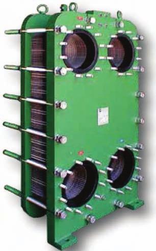
4 2.0 Design and Function The frame consists of a fixed and a loose pressure plate which are held together by two support bolts and tensioning screws. It is manufactured in standard sizes depending on the number of plates in the plate package. The plates are assembled in such a way that every second plate is rotated 180 degrees from the neighbouring plate in the same plane, whereby the ribs criss cross at a number of evenly spaced out bearing points. This results in considerable advantages in terms of strength and heat transfer. What s more, the plates cannot be deformed or damaged if the plate package is clamped. The crossed ribbing creates a very high degree of turbulence in the bundled layers, and results in a high coefficient of thermal conduction (K-value) and reduces the risk of deposits and blockage from e.g. sludge. 3.0 Installation 3.1 Setting up the Plate Heat Exchanger Once the plate heat exchanger has been brought to its final position, it is to be assembled on the floor or on a foundation (plant structure). The heat exchanger should only be fixed to the ground using the holes provided in the frame feet. Changes must be agreed upon with BÖHMER! The plate heat exchanger should be assembled with extra space on both sides, min. 600mm, making it possible to carry out all servicing and maintenance work on the device without problem in future. Copyright Anlagenbau Böhmer GmbH 08/2014 min. 600mm

5 3.2 Environmental Conditions The standard plate heat exchangers are designed for use in closed rooms away from the effects of frost. Special configuration would be required for an outdoor set up. If the plate heat exchanger has to be stored outdoors, it must be protected from climatic influences such as moisture, sunlight and frost by means of an appropriate encasement. An anti-corrosion agent (e.g. grease) should be added to the tensioning screws. 3.3 Pipe Connections The assignments of the connections of each plate heat exchanger take place on an individual basis and this is specified in detail in the job-related documentation. The connections of the exchanger are marked on the pressure plate as follows: Medium A Medium A Medium B Medium B - IN OUT IN OUT The heat exchanger may not be used as a prop or as a support for the pipes. Long or heavy pipes ending in the exchanger are to be supported by other props or holders. There is a danger that the connections may bend under the weight of the pipes, leaving these no longer functional or leaky.! 3.4 Shut-off Valves Each of the connections should be equipped with shut-off valves to enable the opening of the heat exchanger if need be 3.5 Connections on the Loose Pressure Plate Some heat exchangers have connections on the loose pressure plate too. These pipe connections should preferably be made with pipe bows which can be taken away easily, making it possible to move the loose pressure plate when the plate package must be opened.
6 3.6 Pumps If the pumps reach a higher pressure than that allowed in the plate heat exchanger, they are to be provided with an adjusting valve. The intake of air by the pumps must be prevented. If the heat exchanger is operated at a higher pressure than permitted, or exposed to pressure surges from air intake, this can cause a defect in the seals and thus a leakage. 4.0 Putting into Service 4.1 Putting the Plate Heat Exchanger into Service 1. Before putting new PHEs into service, it should be checked whether the plate package is clamped at the right tension factor. Re-clamp as under 5.7 if need be. 2. Check whether the media, the pressure and temperature difference match the job-related specifications. 3. Check that the pipes have been assembled correctly. 4.2 Initiating the Device - Start-up When starting up the heat exchanger, the two inlet valves are to be opened simultaneously and the rate of flow is to be increased slowly until the normal working temperature and the specified pressure are obtained. Pressure shocks or fluid shocks must absolutely be avoided. Take care that vibrations or pressure surges generated by pumps or similar devices do not transmit to the heat exchanger. The plate heat exchanger must be checked for water tightness (visual check) and fault-free functioning (monitor operational data) by trained personnel at regular intervals (at least once a month) Differential Pressure CAUTION! The maximum differential pressure (see type plate) must not be exceeded when operating the heat exchanger, nor during potential pressure checks.
7 4.3 Ventilation The air vent valves on the pipes should be opened during the slow start up, so that the existing air in the heat exchanger may escape. Following complete ventilation (achieved when the media exits from the outlet valve), the air vent valves must be closed again. If you fail to carry out ventilation when filling the plate heat exchanger, air cushions may form on the inside which will compromise the PHE s heat transfer. 4.4 Power Off - Shutting Down the Plate Heat Exchanger The PHE should be stopped slowly by closing the supply valves. Close the flow direction with the higher pressure first or, if the pressure is the same, close the side with the hot medium first. If the heat exchanger is to be taken out of service for a prolonged period (more than 4 weeks), it must be emptied. Rinse or clean the plate package if necessary as described under 5.0. Then declamp the plate package. If there is a risk of frost or aggressive media, the heat exchanger must be emptied immediately after being shut down.
8 5.0 Servicing / Maintenance 5.1 Basic Instructions The user instructions (see 1.1) and the safety instructions (see 1.2) must also be read before any servicing work. The guarantee for the plate heat exchanger is 24 months. During this time, servicing and maintenance work may not be carried out without the consent of BÖHMER, otherwise the guarantee will become void. Here we refer you to our General Terms and Conditions. Due to the various operating conditions and the variety of different media which may be used, the necessary servicing intervals vary. Therefore it is recommended that the plate heat exchanger be serviced in open condition at least once a year, in addition to the monthly visual inspection described under 4.2. CAUTION RISK OF INJURY Maintenance work on the PHE involves a risk of injury. So always bear the following points in mind: 1. Always wear suitable protective equipment (protective gloves, safety boots, safety goggles), the plates are sharp-edged - risk of cuts! 2. When using hazardous flow media (corrosive, toxic, combustible, explosive etc.) there is an acute risk of injury for the operator and bystanders. Ensure that the regulations for flow media are followed during all work. 3. If a pressurised or full plate heat exchanger is opened, the flow media may escape uncontrollably. In this there is a risk of injury for operators and bystanders. Ensure that the plate heat exchanger has adopted the ambient pressure. 4. There is a risk of combustion or freezing if very hot or very cold flow media are used. Always ensure that the plate heat exchanger has adopted the ambient temperature before beginning any maintenance work (e.g. by means of the temperature display on the ingoing and outgoing pipes). 5. Empty the plate heat exchanger and ensure while doing so, that the media in the plate heat exchanger is securely captured in line with environmental guidelines, in order to avoid pollution to the environment.
 3. Note the current tension factor. 4.")
9 5.2 Opening the Plate Heat Exchanger B m a x. B m in. 1. Rinse the outside of the plate heat exchanger. Carrier roller, top carrying bar and bottom plate guide. 2. Clean and grease the tensioning screws (this way the nuts can be loosened more easily later) 3. Note the current tension factor. 4. Mark the plate package at the side with a diagonal colour strip so that you can keep track of the right order of the plates during reassembly. 5. Take the tensioning screws out of the loose plate. The first section of tensioning screws can be loosened in any desired order. Leave the four tensioning screws (1, 2, 3 and 4) for now. Tensioning screws 1-4 are then loosened in diagonally opposing pairs at a time. In the process, in its inclined position, the loose plate may not exceed 10mm of its width and it may not exceed 20mm of its diagonal After all the tensioning screws have been loosened, the loose plate can be pushed back to the support (might be worth securing against slippage). Now the plates may be removed from the frame. Removed plates must always be worked on and stored in a lying position. Never undo the tensioning screws on the fixed plate! Protective gloves should be worn when working with the plate heat exchangers because the plates may be sharp-edged. Only install and remove plates individually - risk of accident!
10 5.3 Cleaning the Plates Light to moderate dirt can be removed from the plates with a high-pressure cleaner. Here it is important that you maintain sufficient distance, as otherwise the water pressure can cause the seals to come apart from the sealing groove. Light soiling of the plates can also be cleaned with running warm water and soft brushes. Generally speaking, care should be taken when cleaning the plates to ensure that the seals are not damaged. Steel wool or steel brushes may not be used. In the case of very sticky coatings, dirt on the plates can be dissolved using chemical baths. Cleaning chemicals should be selected which will not damage the sealing and plate materials. For this, please refer to BÖHMER to select a suitable cleaning agent 5.4 Replacing Seals The seal is formed in one piece. The material is generally an elastomer which is selected on account of its suitability for the chemical and thermal conditions. Our range includes two different types of seal design: 1. Non-adhesive (clip) seal. Old seals can be removed easily from the plates. The sealing groove should be cleaned carefully before inserting the new seals. The special pimples on the seals must be pushed into the corresponding holes on the plate. 2. Glued seals. To remove old seals, the plates must be warmed on the reverse side with hot air. Here it is important to ensure that the plates do not become overheated (heat tinting). For this reason, 150 C should not be exceeded. The adhesive becomes soft after heating and the seal can be removed. The plates should be cleaned of adhesive and old sealant residue (with a blunt object -plastic or wood -no metal ) as well as oil and grease.the relevant cleaning agent can be purchased from us with the associated safety data sheet 3. In order to ensure that the correct spare parts are ordered, every heat exchanger is issued with the relevant documentation on delivery. This lists the components of the exchanger with item numbers. This spare parts list must be stored away safely. Furthermore, data can be requested from BÖHMER using the serial product number with which every heat exchanger is issued.

 and then weighed down with a level steel sheet. At room temperature, the adhesive will set after approx. 12 hours.")
11 The new seal is attached as follows: Apply the glue to the plate in the relevant sealing groove using a small brush or our adhesive application set. Then insert the seal in the groove and push in by hand. Protective gloves must absolutely be worn in this work to avoid contact with skin. We recommend using disposable gloves for this. Adhesive sealant with the associated safety data sheet can be purchased through BÖHMER. Ready-sealed plates should be stacked on a level surface (max. 60 plates on top of one another) and then weighed down with a level steel sheet. At room temperature, the adhesive will set after approx. 12 hours. The setting time can be shortened with higher temperatures: At 40 C reduced to 180 min at 70 C reduced to 45 min at 110 C reduced to 10 min. After setting, excess adhesive should be removed with a blunt object. 5.5 Inserting the Rubber Bushing The rubber bushing is installed on the front side of the thrust plate by bending the bushing in order to push it inside through the opening. The rubber bushing must be laid out smoothly on the inside and placed in such a way (horizontal + vertical alignment), that the rubber ring on the bushing sits perfectly in the heat exchanger plate groove (only with the old design). The new design does not feature a rubber ring on the inside, therefore a complete initial sealing with 4 ring-seals must be installed.

12 5.6 Assembly The seal and the plates must be carefully inspected before assembly. Dirt or particles which could lead to a leakage must be removed. If one or more plates have received new seals, it must be checked whether these are sitting perfectly in the guide. Before the movable thrust plate is pushed against the plate package, check to ensure that the plates are correctly fitted in the frame - the edges of the plates should then form a honeycomb pattern. The colour strip applied before opening allows an extra visual check. B B m a x. m in. Protective gloves should be worn when working with the plate heat exchangers because the plates may be sharp-edged. Only install and remove plates individually - risk of accident! 5.7 Tensioning The plate package must be tensioned up to a certain degree between the inner surfaces of the fixed and the movable thrust plates. This degree is calculated as follows: Number of plates x multiplier Please use the enclosed separate sheet tension factor to find out the relevant multipliers of the various heat exchanger types. Tensioning the plate package at less than B-min is not permitted. When the package is fixed at B-min, the metal of the plates are in contact with one another; a further tensioning could result in the deformation of the plates.

13 When tightening, ensure that the screw s torque is not exceeded. You can find a corresponding table with the respective torques at the end. Please refer to the job-related documentation for the size of the tensioning screws. When tightening the screws, you must never tighten beyond the tension factor, even if the torque would allow further movement. The moveable thrust plate must not be at an angle in the frame, it must always be moved parallel to the fixed thrust plate. Not all tensioning screws need to be tightened at the start. You can begin with two screws on each side, namely with the two in the middle (1, 2, 3, 4). This way the plate package can be tensioned to around 30 % above B-min. Then the tensioning is continued with all the tensioning screws. The tension factor B-mas. is sufficient for new seals. After a prolonged operating duration, it may be necessary to re-tension the plate package in order to avoid leaks The heat exchanger must never be re-tensioned when pressurised! The function and lifespan of the heat exchanger are highly dependent on the accuracy of the plate package tensioning.
14 6.0 Troubleshooting LEAK between plate package and frame Mark the spot with a felt pen or the like and open the heat exchanger as described under 5.2, observing all the safety instructions while doing so. 1. Check the condition of the seal on the end plate and, if applicable, the connection. Watch out for any potential damage on the seals. 2. Examine the surface of the thrust plate for unevenness, foreign particles stuck to it etc., which could destroy the connection between the seal and the adjacent surface. Remedy: 1. Remove foreign particles. 2. Replace damaged seals. 3. Replace rubber bushing, if present. Outward LEAK between the plates Mark the leak area with a felt pen and measure and note the length of the plate package between the thrust plates (tension factor). Open the heat exchanger (see 5.2) while observing all the safety rules. Inspect the plates: 1. Examine loose or damaged seals. 2. Check plates for deformation, pitting and cracks. 3. Sort faulty plates and/or plates with faulty sealings. Remedy: 1. Restick or reclip loose seals. Replace faulty seals. 2. Take out faulty plates for repair or replace with a new plate. 3. When assembling the heat exchanger, observe the corresponding tension factor (see tension factor table and point 5.7).
15 Mixing of media - internal leak Procedural steps for localising leakage 1. Observe the safety rules 2. Shut down pumps and leave device to cool to room temperature. 3. Empty the exchanger and open the lower pipe connection at the inoperative flow area. Apply light pressure to the opposite side (pipe pressure). 4. The leak becomes visible if liquid escapes from the opened connection. In this case mark the point externally on the plate package and proceed further as described under Cracks or corrosion on the plate can be localised using a powerful light source (torch or headlight). 6. Tests with dye penetrants are required to detect very fine hairline cracks or holes in the plates. Refer to Böhmer in this case. Remedy: 1. Replace the faulty plates 2. As a temporary solution, the exchanger can be operated with a reduced number of plates until a replacement is available. Drop in performance of the plate heat exchanger If pressure losses rise considerably or if the heat output falls significantly, you must first check if this is to be attributed to a fault in the overall unit. Check process and operational data. If this is not the case, the plate heat exchanger must be opened and cleaned as described under point 5.0. Copyright Anlagenbau Böhmer GmbH 08/2014
16 Tension factor for plate heat exchangers 0,4mm 0,5mm 0,6mm 0,7mm 0,8mm 1,0mm Safety plate-2x0,35mm Safety plate-2x0,5mm type Min. Max. Min. Max. Min. Max. Min. Max. Min. Max. Min. Max. PAB 380 2,7 2,8 PAB ,75 2,85 2,8 2,9 PAB 403, 405, ,25 2,35 PAB ,6 2,7 2,7 2,8 PAB 410, ,9 3,0 3,0 3,1 3,1 3,2 PAB 411 2,9 3,0 3,0 3,1 PAB 415, ,8 2,9 2,9 3,0 3,0 3,1 PAB ,9 3,0 3,0 3,1 PAB 431,432,433,434,435, ,95 3,1 3,05 3,15 3,2 3,3 PAB 448, ,8 3,9 3,9 4,0 4,0 4,1 PAB 456, ,9 4,0 4,0 4,1 PAB 460, 461, ,9 4,0 4,0 4,1 PAB ,3 3,4 PAB plates 0,9mm >> 5,9 6,0 PAB 490, ,8 2,9 2,9 3,0 3,0 3,1 3,1 3,2 3,2 3,3 PAB 491 4,2 4,3 4,3 4,4 4,4 4,5 4,5 4,6 PAB ,75 2,85 2,85 2,95 PAB ,9 3,0 3,0 3,1 3,1 3,2 PAB ,95 3,1 3,05 3,2 3,15 3,3 PAB 531 2,95 3,1 3,05 3,2 3,55 3,7 PAB 541, 543, ,8 2,9 2,9 3,0 3,0 3,1 3,1 3,2 PAB 542 4,1 4,2 4,2 4,3 4,3 4,3 4,4 4,5 PAB 550 3,3 3,4 3,4 3,5 3,5 3,6 PAB 556, ,35 3,5 3,45 3,6 3,55 3,7 3,85 4,0 PAB 560 3,55 3,7 3,65 3,8 3,75 3,9 PAB 590, 522, ,95 3,1 3,05 3,2 3,45 3,6 PAB 612 3,2 3,3 3,3 3,4 PAB 614 4,2 4,3 4,3 4,4 PAB 615 3,65 3,72 3,75 3,82 PAB ,2 4,3 4,3 4,4 PAB 651, 653, ,55 3,65 3,65 3,75 PAB 656, ,95 3,1 3,05 3,2 PAB 703 2,5 2,6 PAB 705 2,9 3,0 PAB 712 3,3 3,5 3,5 PAB 714 2,25 2,35 2,45 PAB 718, ,65 3,75 3,75 3,85 3,9 4,0 PAB 720 4,3 4,5 4,4 4,6 PAB 724 3,1 PAB ,1 2,2 2,3 PAB 736 4,3 4,5 4,4 4,6 4,5 4,7 PAB ,7 2,8 PAB 744 4,8 5,0 4,9 5,1
Installation, Operation and Maintenance Instructions for ThermaFlex Gasketed Plate Heat Exchangers
 OM010 Installation, Operation and Maintenance Instructions for ThermaFlex Gasketed Plate Heat Exchangers The operating and maintenance instructions contained within this package are for ThermaFlex gasketed
Installation, Operation and Maintenance Instructions ThermaFlex Gasketed Plate Heat Exchanger OM010
 Installation, Operation and Maintenance Instructions ThermaFlex Gasketed Plate Heat Exchanger OM010 Calorifiers Heat Exchangers Pressurisation Units Sales Tel: 01457 835700 Sales Fax: 01457 832700 E-mail:
Rycroft Supapac Plate Heat Exchangers
 Rycroft Supapac Plate Heat Exchangers Installation Operation & Maintenance Manual Ormandy Rycroft Duncombe Road Bradford BD8 9TB England TEL +44 (0)1274 490911 FAX +44 (0)1274 498580 www.rycroft.com 1.
PLATE HEAT EXCHANGERS. Operation and Maintenance Manual
 PLATE HEAT EXCHANGERS Operation and Maintenance Manual Operation and Maintenance Manual TABLE OF CONTENTS A. Plate Heat Exchanger Description B. Construction and Function C. Plate Characteristics D. Gasket
HRS Heat Exchangers Instruction Manual
 HRS Heat Exchangers Instruction Manual Plate Heat Exchanger Ceteplate HRS032, HRS140, HRS150, HRS220 and HRS240m Information courtesy of Cetetherm Table of contents Table of contents Description... 1 Main
PLATE HEAT EXCHANGER
 PLATE HEAT EXCHANGER Type Sxx-xx-xx Serie-No.: xxxxx/xx/x Operating & maintenance Contents page Construction and function 2 Plate construction 3 Plate type 4 Drawings and name plate 5-6 Gasket construction
Pump assembly Instruction manual
 Instruction manual EN Version 2.0 /Release 06/2012 Table of content 1 Key background information...3 1.1 Limitation of liability...3 1.2 Responsibilities of the operator...3 1.3 Documentation...3 1.3.1
Instruction Manual Plate Condenser. AlfaCond 400/600/800. Part number
 Instruction Manual Plate Condenser AlfaCond 400/600/800 Part number 34502490 0904 Table of contents English Table of contents Description... 1 Main components... 1 Function... 2 Installation... 3 Requirements...
Description. Main components. Lifting eyes To used for lifting and transport securing. Carrying bar Carries the cassettes and the pressure plate.
 Description English Description Main components Lifting eyes To used for lifting and transport securing Frame plate Carrying bar Carries the cassettes and the pressure plate. Support column Connections
Mechanical seals external, single or double, to DIN EN 12756
 INSTALLATION AND OPERATING MANUAL Translation of the original manual Series SCK Bearing pedestal group: 0 Mechanical seals external, single or Keep for future use! This operating manual must be strictly
CENTAFLEX Series A Assembly and operating instructions CF-AR M EN Rev. 2
 Contents 1 General remarks... 5 2 Safety... 6 2.1 Safety remarks... 6 2.1.1 Signal words... 6 2.1.2 Pictograms... 7 2.2 Qualification of deployed personnel... 7 2.3 Intended application... 7 2.4 Application
Installation, Operation and Maintenance LOK-FLANGE Multitube Heat Exchangers
 Bulletin 1200/4 (Revised 5/12) Installation, Operation and Maintenance LOK-FLANGE Multitube Heat Exchangers INNOVATORS IN HEAT TRANSFER I. INSTALLATION OF HEAT EXCHANGERS A. HEAT EXCHANGER SETTINGS 1)
INSTALLATION, OPERATION, AND MAINTENANCE MANUAL
 INSTALLATION, OPERATION, AND MAINTENANCE MANUAL TUBE AXIAL FANS BTA, WTA, HTA, DDA The purpose of this manual is to aid in the proper installation and operation of the fans. These instructions are intended
SAFETY AND OPERATING MANUAL
 SAFETY AND OPERATING MANUAL 2 General Safety Warnings WARNING: Read all safety warnings and all instructions. Failure to follow the warnings and instructions may result in electric shock, fire and/or serious
LONGONI ENGINEERING SRL
 INDEX 1.1 Classification of heat exchanger and components 1.1.2 Type of heat exchanger and components 1.2 Purpose and scope of the manual 1.3 General instruction 1.4 Warning installation 1.5 Notes for
Operation and Maintenance Manual Sondex All-Welded Heat Exchangers (SAW)
") Operation and Maintenance Manual Sondex All-Welded Heat Exchangers (SAW) The contents of this publication are based on the latest information available and the materials that are used at the time of printing.
Operation and Maintenance Manual Sondex All-Welded Heat Exchangers (SAW) The contents of this publication are based on the latest information available and the materials that are used at the time of printing.
Specifications. Vacuum motor power consumption(w/hp) 1200 / 1.6. Exhaust water pump power consumption(w/hp 800 / 1.1
 1200 / 1.6. Exhaust water pump power consumption(w/hp 800 / 1.1") Specifications Rated voltage (V) AC 110-120V or 220-240V / 50-60Hz Vacuum motor power consumption(w/hp) 1200 / 1.6 Exhaust water pump power consumption(w/hp 800 / 1.1 Exhaust water pump flow (GPH/LPH)
Specifications Rated voltage (V) AC 110-120V or 220-240V / 50-60Hz Vacuum motor power consumption(w/hp) 1200 / 1.6 Exhaust water pump power consumption(w/hp 800 / 1.1 Exhaust water pump flow (GPH/LPH)
SOVEREIGN W Grass Trimmer (Model: GT2317) Instruction Manual. Important - Please read these instructions fully before starting assembly
 Instruction Manual. Important - Please read these instructions fully before starting assembly") SOVEREIGN 2937573 250W Grass Trimmer (Model: GT2317) Instruction Manual After Sales Support UK/Ireland 0345 640 0800 Web www.argosspares.co.uk Important - Please read these instructions fully before starting
SOVEREIGN 2937573 250W Grass Trimmer (Model: GT2317) Instruction Manual After Sales Support UK/Ireland 0345 640 0800 Web www.argosspares.co.uk Important - Please read these instructions fully before starting
D O U B L E A U G E R M O R TA R M I X E R OWNER S MANUAL
 D O U B L E A U G E R M O R TA R M I X E R OWNER S MANUAL WARNING: Read carefully and understand all INSTRUCTIONS before operating. Failure to follow the safety rules and other basic safety precautions
Steam Trap BK 45 BK 45-U BK 45-LT BK 46
 Steam Trap BK 45 BK 45-U BK 45-LT BK 46 Original Installation Instructions 810437-08 Contents Foreword... 3 Availability... 3 Formatting features in the document... 3 Safety... 3 Use for the intended purpose...
Installation and operating instructions. DK energy storage and DK energy buffer
 Installation and operating instructions DK energy storage and DK energy buffer Edition: 08-2015 1 Preliminary note With this DK energy storage / DK energy buffer you purchased a DK quality product. The
FSW300 Series Flow Switch
 . FSW300 Series Flow Switch - 2 - Series FSW300 Series FSW300 Table of contents page 0 About this operating manual... 4 1 Device description... 5 1.1 Intended use... 5 1.1.1 Reed contact - Switching of
Operating Instructions. PowerFill. Automatic Granulate Conveyor for perfectmelt SE
 Operating Instructions PowerFill Automatic Granulate Conveyor for perfectmelt SE - 020100 - 2 Contents Introduction 4 Safety instructions 5 Safety measures with respect to the adhesive 5 Safety measures
ENGLISH (Original instructions) INSTRUCTION MANUAL. Demolition Hammer HM0810TA DOUBLE INSULATION. IMPORTANT: Read Before Using.
 INSTRUCTION MANUAL. Demolition Hammer HM0810TA DOUBLE INSULATION. IMPORTANT: Read Before Using.") ENGLISH (Original instructions) INSTRUCTION MANUAL Demolition Hammer HM080TA 00079 DOUBLE INSULATION IMPORTANT: Read Before Using. ENGLISH (Original instructions) SPECIFICATIONS Model HM080TA Blows per
ENGLISH (Original instructions) INSTRUCTION MANUAL Demolition Hammer HM080TA 00079 DOUBLE INSULATION IMPORTANT: Read Before Using. ENGLISH (Original instructions) SPECIFICATIONS Model HM080TA Blows per
Channel plates Heat is transferred from one medium to the other through the thin channel plates.
 Description English Description Main components Frame plate Carrying bar Carries the channel plates and the pressure plate. Support column Tightening bolts Press the channel plates together. Bolt protection
SERVICING INFORMATION
 SERVICING INFORMATION OPTIKINETICS SOLAR 250 (Early Type) M.Ginda 06/03/08 1 Servicing the Solar 250 effects projector. This is a short guide on how to service the main component parts of the projector.
Instruction Manual Suppository Penetration Tester. Type PM 30
 Instruction Manual Suppository Penetration Tester Type PM 30 ERWEKA GmbH * Ottostr. 20 22 * 63150 Heusenstamm * Germany * Tel: +49 (0) 6104 6903-0 Fax: +49 (0) 6104 6903-40 * E-mail: info@erweka.com *
Product instruction manual Easymount Wide Format Laminators
 Product instruction manual Easymount Wide Format Laminators The Easymount has been designed to be user friendly, however we strongly recommend you take a few minutes to read through this manual to ensure
Instruction Manual - Plate Heat Exchangers
 EN Instruction Manual - Plate Heat Exchangers IT M15, TL10, TL15, T20, TS20, MX25, MA30, WideGap 100, WideGap 200 FI LT 3490017598-EN 2016-06 Original manual Table of contents EN Preface... 4 Safety considerations...
DEUTSCH Bio-Master Bio-Max
 DEUTSCH D 8217-3029-02 Bio-Master Bio-Max SVENSKA S 4. 2. 1. 3. 4. 5. 3 S SVENSKA 7. 6. 8. 9. 10. 4 SVENSKA S 11. 12. 4. 13. 4. 15. 14. 5 GB ENGLISH SAFETY PRECAUTIONS GENERAL This symbol means WARNING.
KITCHEN EXHAUST FAN GLEC-6 INSTALLATION AND MAINTENANCE
 KITCHEN EXHAUST FAN GLEC-6 INSTALLATION AND MAINTENANCE 2 GLEC-6 - Installation and maintenance CONTENTS 1 Important information... 3 2 Safety notes... 3 3 Technical description...4 4 Transport... 6 5
USER S MANUAL BUCKET FAN SERIES BUCKET FAN WHISPER SERIES
 USER S MANUAL BUCKET FAN SERIES BUCKET FAN WHISPER SERIES Bucket Fan 420 Bucket Fan 1055 Bucket Fan 1460 420 1055 1460 2 Bucket Fan CONTENT INTRODUCTION 3 USE 3 WHAT S INCLUDED IN THE BOX 3 DESIGNATION
One-Touch Dispense. Multi-temp selections. 208 F For tea, coffee, instant noodle. 194 F Keep warm around 194 F. 176 F Keep warm around 176 F.
 Instruction Manual Automatic Dispensing Hot Water Pot with Multi-temperature Function Automatic Dispensing One-Touch Dispense FEATURES Reboil Function 5 Temperature Settings Image Of SP-5016 208 F For
TCUT10UL 2.5 HP 10 Tile Saw Assembly & Operating Instructions
 TCUT10UL 2.5 HP 10 Tile Saw Assembly & Operating Instructions READ ALL INSTRUCTIONS AND WARNINGS BEFORE USING THIS PRODUCT. This manual provides important information on proper operation and maintenance.
Instruction Manual. Pharma-line ESE02198-EN Original manual
 Instruction Manual Pharma-line ESE02198-EN 2012-05 Original manual Table of contents The information herein is correct at the time of issue but may be subject to change without prior notice 1. Description...
Ultra Clean LAMBTON CONVEYOR LIMITED. Installation and Operation Manual ONE SOURCE ONE SOLUTION
 Ultra Clean Installation and Operation Manual LAMBTON CONVEYOR LIMITED ONE SOURCE 1 Contents Warranty... 4 Section 1. Safety... 5 Section 2. Decals... 8 Section 3. Product Information... 9 Ultra Clean
Friwa Compact. Operating instructions EN
 Operating instructions EN Version 1.1 / Edition 09/2013 Contents 1 Key background information... 3 1.1 Limitation of liability... 3 1.2 Responsibilities of the operator... 3 1.3 Documentation... 3 1.3.1
HEAT RECOVERY AIR HANDLING UNIT
 HEAT RECOVERY AIR HANDLING UNIT OPERATION MANUAL KOMFORT_L v2(2)_en.indd 1 07.08.2015 15:0:44 CONTENTS Introduction General Safety regulations Transportation and storage regulations Manufacturer's warranty
Titanium Plate Heat Exchanger. Installation & Operating Manual
 Titanium Plate Heat Exchanger Installation & Operating Manual Congratulations on your purchase of your Elecro Titanium PLATE HEAT EXCHANGER, manufactured in Hertfordshire, England to exacting standards
Operating instructions
 ebm-papst Mulfingen GmbH & Co. KG Bachmühle D-74673 Mulfingen Phone +49 (0) 793-0 Fax +49 (0) 793-0 info@de.ebmpapst.com www.ebmpapst.com CONTENTS. SAFETY REGULATIONS AND NOTES. Levels of hazard warnings.
TECHNICAL INFORMATION T 15xx Dryers
 TECHNICAL INFORMATION T 15xx Dryers 2010 Miele USA Table of Contents 1.0 2.0 3.0 T 15xx Dryers Construction and Design... 5 1.1 Appliance Overview Vented Models... 5 1.2 Appliance Overview Condenser Models...
INSTRUCTION MANUAL MODEL: 690E
 1 INSTRUCTION MANUAL ALEKO Drywall Sander MODEL: 690E READ THROUGH CAREFULLY AND UNDERSTAND THESE INSTRUCTIONS BEFORE USE Visit our web site for more great products, parts and accessories: 2 3 4 5 6 Caution!
WesPlate. Operation, Maintenance & Installation Manual. Heat Exchanger. Models WP & WPDW
 WesPlate Heat Exchanger Models WP & WPDW Operation, Maintenance & Installation Manual TABLE OF CONTENTS Section 1.0 Plate Heat Exchangers Working Principle 2.0 Parts & Their Function 2.1 Frames 2.2 Plates
Indholdsfortegnelse. Danvent Air Handling Units SERVICE MANUAL
 Indholdsfortegnelse Danvent Air Handling Units SERVICE MANUAL Service Servicing of the Air Handling Unit Your ventilation system is equipped with a Danvent Air Handling Unit (AHU) which will contribute
Operating Instructions
 Operating Instructions BA-003 Read and understand this manual before use. Keep this manual for future reference. CONFORMS TO UL STD.No.1017 Certified to CSA STD C22.2 No.243-10 For questions or concerns
Series 1140 and 1141 Temperature Regulators
 Hoffman Specialty Installation & Maintenance Instructions HS-504(E) Series 1140 and 1141 Temperature Regulators! CAUTION FOLLOW ALL INSTALLATION AND OPERATING INSTRUCTIONS. TURN OFF WATER OR STEAM BEFORE
Owner's Manual. Please read this document carefully before installing and/or using your vacuum cleaning system.
 Owner's Manual for household use only Please read this document carefully before installing and/or using your vacuum cleaning system. Model : Serial No : Important Safety Instructions When using an electrical
Operating Guide. Termix Compact 28 VX-FI / HWP / HWS. 1.0 Table of Contents. 1.0 Table of Contents
 1.0 Table of Contents 1.0 Table of Contents... 1........................................................................ 2 2.0 Functional description... 3 3.0 Safety notes... 4 3.1 Safety Notes general............................................
COPYRIGHT Alfa Laval Lund AB, 2012 How to contact Alfa Laval Contact details for all countries are continually updated on our website.
 Table of Contents English Table of Contents Description... 5 Main components... 5 Name plate... 6 Function... 7 Multi-section... 8 Multi-pass... 9 Identification of plate side... 9 Installation... 10 Before
Wet/Dry Vacuum Kit
 Wet/Dry Vacuum Kit 54-0011-6 Owner ' s Manual Toll-Free Helpline: 1-866-JOBMATE (562-6283) Version 3.3 Table of Contents SECTION Page Specifications...2 Safety Warnings... 3 Location of Parts..... 5 General
TECHNICAL INFORMATION Touchtronic Clothes Dryers
 TECHNICAL INFORMATION Touchtronic Clothes Dryers Includes: T1302, T1303, T1322, T1329ci T1403 & T1405 2004 Miele This page intentionally left blank. Table of Contents GENERAL INFORMATION A. Warning and
Operating Instructions
 Operating Instructions Varioset Standard After-sales service For after-sales service please contact the Veit representative in your country. GmbH & Co. Justus - von - Liebig - Str. 15 D - 86899 Landsberg
HKF 8180 Operating instructions
 Operating instructions EN Version 1.0en /Edition 05/2013 Contents 1 Important basic information... 3 1.1 Limitation of liability... 3 1.2 Operator's responsibilities... 3 1.3 Documentation... 3 1.3.1 Content
SOUND-INSULATED FAN. Iso-K OPERATION MANUAL. Iso-K_v.1(2)-EN.indd :20:59
-EN.indd :20:59") SOUND-INSULATED FAN OPERATION MANUAL _v.1(2)-en.indd 1 10.08.2015 15:20:59 CONTENT Introduction 3 General 3 Safety rules 3 Transport and storage requirements 3 Manufacturer's warranty 3 Fan design 4 Delivery
SOUND-INSULATED FAN OPERATION MANUAL _v.1(2)-en.indd 1 10.08.2015 15:20:59 CONTENT Introduction 3 General 3 Safety rules 3 Transport and storage requirements 3 Manufacturer's warranty 3 Fan design 4 Delivery
General Maintenance and Operating Instructions for Heat Exchangers
 General Maintenance and Operating Instructions for Heat Exchangers Preamble Due to the diversity of operating conditions and the necessity for transparency and clarity of presentation, the maintenance
Chemical Motor Pump Unit BN
 Operating & Maintenance Instructions BW 5 02 01 / 1 The operating instructions of the centrifugal pump and the accessories should be located close to the pump. These instructions should be read carefully
Operating Manual Bathroom Balance
 KERN & Sohn GmbH Ziegelei 1 D-72336 Balingen email: info@kern-sohn.com Phone: +49-[0]7433-9933-0 Fax: +49-[0]7433-9933-149 Internet: www.kern-sohn.com Operating Manual Bathroom Balance KERN MGB Version
PREMIUM KITCHEN MIXER TAP. PREMIUM KITCHEN MIXER TAP Assembly, operating and safety instructions IAN
 PREMIUM KITCHEN MIXER TAP PREMIUM KITCHEN MIXER TAP Assembly, operating and safety instructions IAN 282471 GB/IE/NI Assembly, operating and safety instructions Page 5 B 15mm HG00476A HG00476B C 5 4 12
ICE CREAM TOPPING CABINETS REFRIGERATOR or FREEZER Installation, Operation and Maintenance Instructions
 ICE CREAM TOPPING CABINETS REFRIGERATOR or FREEZER Installation, Operation and Maintenance Instructions INSPECTION When the equipment is received, all items should be carefully checked against the bill
INSTALLATION MANUAL. Split-type Air Conditioner (Cooling and Heating) Outdoor Unit UQB09JJWC UQB12JJWC. Indoor Unit AQB09JJWC AQB12JJWC
 Outdoor Unit UQB09JJWC UQB12JJWC. Indoor Unit AQB09JJWC AQB12JJWC") AQB09JJ6WC_IM_E_2585 2006.4.17 4:26 PM Page 17 INSTALLATION MANUAL Indoor Unit AQB09JJWC AQB12JJWC Outdoor Unit UQB09JJWC UQB12JJWC ENGLISH FRANÇAIS ESPAÑOL Split-type Air Conditioner (Cooling and Heating)
AQB09JJ6WC_IM_E_2585 2006.4.17 4:26 PM Page 17 INSTALLATION MANUAL Indoor Unit AQB09JJWC AQB12JJWC Outdoor Unit UQB09JJWC UQB12JJWC ENGLISH FRANÇAIS ESPAÑOL Split-type Air Conditioner (Cooling and Heating)
USER S MANUAL ATH WH220
 USER S MANUAL ATH WH220 INDEX INTRODUCTION... - 3 - General information s... - 3 - Description of pneumatic jack... - 4 - Operation of jack... - 5 - Technical data... - 6 - Dimension drawing... - 6 - INSTALLATION...
Montageanleitung RLO (Original) Mounting Instructions RLO (Translation of the original)
 Mounting Instructions RLO (Translation of the original)") Montageanleitung (Original) (Translation of the original) DE MA_ 1.0 06/2014 Taperlock Clamping-bush system _0 _1 Fixed hub Inlet nozzle with IMV 1. Revision index Revision Date MA_ 1.0 06/2014 2. Safety
Montageanleitung (Original) (Translation of the original) DE MA_ 1.0 06/2014 Taperlock Clamping-bush system _0 _1 Fixed hub Inlet nozzle with IMV 1. Revision index Revision Date MA_ 1.0 06/2014 2. Safety
Flameproof Manual Call Points
 Operating instructions Additional languages www.r-stahl.com CS & Clifford & Snell Contents General Information.... Manufacturer.... Information regarding the operating instructions.... Further documents....
Hand Dryer Installation & User Manual
 Hand Dryer Installation & User Manual Please read instructions in conjunction with the illustrations Please save these instructions. Safety & Guidance notes Important:- Read all these instructions before
Power-Spin. Drain Cleaner Operator s Manual
 Drain Cleaner Operator s Manual Power-Spin! Read this Operator s Man ual carefully before using this tool. Failure to understand and follow the contents of this manual may result in electrical shock, fire
Installation Operation Maintenance. Ductable water unit FWD FWD-SVX01D-E4
 Installation Operation Maintenance Ductable water unit FWD 08-12 - 20-30 - 45 General Information Foreword These installation, operation and maintenance instructions are given as a guide to good practice
Waste water ejection unit
 Waste water ejection unit Over ground box SWH 500/50-80 SWH 500/50-80 Operation manual Table of contents: Page Declaration of conformity... 3 1. General... 4 1.1 Introduction... 4 1.2 Enquiries and orders...
GRIND PRO DUAL OR DISC SANDER. Operator Manual
 GRIND PRO DUAL OR DISC SANDER Operator Manual 2 GRIND PRO DUAL OR DISC ORTHO-SANDER INTRODUCTION The Grind Pro Dual or Disc Sander is a compact, durable machine designed for fast, complete finishing work.
AIRGOCLEAN 10 E OPERATING MANUAL AIR CLEANER TRT-BA-AIRGOCLEAN10E-TC-001-EN
 AIRGOCLEAN 10 E EN OPERATING MANUAL AIR CLEANER TRT-BA-AIRGOCLEAN10E-TC-001-EN Table of contents Notes regarding the operating manual... 1 You can download the current version of the operating manual and
G-7s. Instruction Manual. G-Series Cooler COUNTERTOP COOLER. Part No.11IPA
 G-Series Cooler COUNTERTOP COOLER Part No.11IPA-061000 Instruction Manual FOR YOUR FUTURE REFERENCE This easy-to-use manual will guide you in getting the best use of your cooler. Remember to record the
UNDERCOUNTER LABORATORY REFRIGERATORS and FREEZERS Installation, Operation and Maintenance Instructions
 UNDERCOUNTER LABORATORY REFRIGERATORS and FREEZERS Installation, Operation and Maintenance Instructions INSPECTION When the equipment is received, all items should be carefully checked against the bill
rev3 INSTALLATION & OPERATION MANUAL OIL CIRCULATING HEATING SYSTEM MODEL OSM
 216279-000 rev3 INSTALLATION & OPERATION MANUAL OIL CIRCULATING HEATING SYSTEM MODEL OSM IDENTIFYING YOUR SYSTEM IOM216279-000 The HOTSTART heating system is designed to heat fluids for use in marine
STRIP CUT PAPER SHREDDER
 User Manual STRIP CUT PAPER SHREDDER MANUAL DEVELOPED IN GERMANY myhansecontrol.com User-friendly Manual ID: #05007 Contents Overview...3 Use...4 Package contents / device parts...6 General information...
User Manual GV25 GV35 GV702. Company information: Original instructions GV12066 (1)
") User Manual Original instructions GV25 GV35 GV702 Company information: www.vipercleaning.eu info-eu@vipercleaning.com GV12066 (1) 2012-04-10 USER MANUAL ENGLISH TABLE OF CONTENTS Introduction... 4 Manual
User Manual Original instructions GV25 GV35 GV702 Company information: www.vipercleaning.eu info-eu@vipercleaning.com GV12066 (1) 2012-04-10 USER MANUAL ENGLISH TABLE OF CONTENTS Introduction... 4 Manual
Maintain and restore hard floors
 Learning Guide Maintain and restore hard floors 29391 Maintain and restore hard floor surfaces Level 3 10 credits Name: Workplace: Issue 1.0 Copyright 2017 Careerforce All rights reserved. Careerforce
Flow switch. Operating Manual. English manual page Page 1 of 15 Fax:
 Operating Manual www.jlso-tec-trade.de Flow switch English manual page 1-15 Page 1 of 15 Flow switch Table of Contents Page 1 Device Description and Intended Use... 19 1.1 Flow switch version VH...X...
INLINE СENTRIFUGAL FAN BOX BOX-R OPERATION MANUAL
 INLINE СENTRIFUGAL FAN BOX BOX-R OPERATION MANUAL CONTENT 3 Introduction 3 General 3 Safety rules 3 Storage and transportation rules 3 Manufacturer s warranty 4 Fan design 4 Delivery set 5 Technical data
Operating Instructions. Accessory Units Melitta Cafina XT Series. Melitta Professional Coffee Solutions
 Operating Instructions Accessory Units Melitta Cafina XT Series Melitta Professional Coffee Solutions Contents General... 4. Manufacturer information... 4.2 About these instructions... 4.3 Explanation
DUST EXTRACTOR MODEL No: CDE1000
 DUST EXTRACTOR MODEL No: CDE000 Part No:64765 OPERATING & MAINTENANCE INSTRUCTIONS GC054 INTRODUCTION Thank you for purchasing this CLARKE Dust Extractor which is intended to keep work areas free from
AIR COMPRESSOR TC UTC TC UTC125502
 AIR COMPRESSOR TC120242 UTC120242 TC125502 UTC125502 Warning! When using compressors, basic safety precautions should always be followed to reduce the risk of fire, electric shock and personal injury.
PUDDLE PUMP PUDDLE PUMP. MODEL No: PSP125 OPERATION & MAINTENANCE INSTRUCTIONS. Part No:
 PUDDLE PUMP PUDDLE PUMP MODEL No: PSP125 Part No: 7230692 OPERATION & MAINTENANCE INSTRUCTIONS 1007 SPECIFICATIONS Model number... PSP125 Rated voltage... 230VAC 50Hz Input power... 293 Watts Maximum delivery
Operator s Manual. 2.5 Gallon Model No. VOM205P FOR YOUR SAFETY. Read and understand this manual before use. Keep this manual for future reference.
 Wet/Dry Vacuums Operator s Manual 2.5 Gallon Model No. VOM205P FOR YOUR SAFETY Read and understand this manual before use. Keep this manual for future reference. www.vacmaster.com Cleva North America 44
TECHNICAL INFORMATION T1500 Series Clothes Dryers
 TECHNICAL INFORMATION T1500 Series Clothes Dryers 2003 Miele - Table of Contents 1.0 CONSTRUCTION & DESIGN 1.1 Appliance Overview - Vented 1 1.2 Appliance Overview Condenser Models 2 1.3 Controls Overview
K Specifications. Max. Water Volume
 K 2.75 High Pressure Washer Operator Manual Overview... 2 Precautions... 2-4 Assembly Instructions... 4 Operating Instructions... 5 Using the Accessories... 6 Working with Detergents... 7 Shut Down and
Mechanical Seal RG-4 stationary, double, liquid sealed
 Series SCK INSTALLATION AND OPERATING MANUAL Translation of the original manual Mechanical Seal RG-4 stationary, double, liquid sealed Keep for future use! This operating manual must be strictly observed
Evaporators. Direct Expansion Flooded Recirculated Over Feed
 Evaporators Purpose: Liquid Refrigerant is Boiled from a Low Pressure Liquid to a Low Pressure Gas by Absorbing Heat from the Medium that is being Cooled Types: Direct Expansion Flooded Recirculated Over
CHAPTER 1 SAFETY SUMMARY CHAPTER 2 MACHINE FAMILIARIZATION CHAPTER 3 UNPACKING AND INSTALLATION CHAPTER 4 OPERATION INSTRUCTION
 ===== CONTENTS ===== CHAPTER 1 SAFETY SUMMARY 1-1 INTRODUCTION 3 1-2 SAFETY DURING INSTALLATION 3 1-3 SAFETY DURING OPERATION 3 1-4 PRECAUTIONS DURING OPERATION 4 1-5 SAFETY DURING MAINTENANCE 4 1-6 SAFETY
Food Waste Disposer Instruction Manual
 Food Waste Disposer Instruction Manual See insert for specific information about your new disposer NOTE: IMPORTANT: CAUTION: This Food Waste Disposer has been designed to operate on 110-120 Volt, 60 Hz
TTV 1500 / TTV 3000 OPERATING MANUAL CONVEYING FAN TRT-BA-TTV TC EN
 TTV 1500 / TTV 3000 EN OPERATING MANUAL CONVEYING FAN TRT-BA-TTV1500-3000-TC2016-26-004-EN Table of contents Notes regarding the operating manual... 2 You can download the current version of the operating
EHA Hoffmann International GmbH
 EHA Hoffmann International GmbH User manual EHA-TRANSPRINT HP 2020 Machine-No.: Year: EHA Hoffmann International GmbH Michelsbergstraße 24 D-57080 Siegen/Germany Telephone: +49 271 39 32-0 Telefax: +49
Operator s Manual. Wet/Dry Vacuum with Detachable Blower 12 Gallon Model No. VBV1210 FOR YOUR SAFETY
 Wet/Dry Vacuums Operator s Manual Wet/Dry Vacuum with Detachable Blower 12 Gallon Model No. VBV1210 FOR YOUR SAFETY Read and understand this manual before use Keep this manual for future reference www.vacmaster.com
RX550i Electric Pressure Washer
 RX550i Electric Pressure Washer READ THIS MANUAL CAREFULLY BEFORE USE FAILURE TO DO SO MAY RESULT IN INJURY, PROPERTY DAMAGE AND MAY VOID WARRANTY. KEEP THIS MANUAL FOR FUTURE REFERENCE. Products covered
Operating Guide. Termix Solar A+/B+ 1.0 Table of Contents. 1.0 Table of Contents
 1.0 Table of Contents 1.0 Table of Contents... 1........................................................................ 2 2.0 Functional description... 3 3.0 Safety notes... 4 3.1 Safety Notes general............................................
20-GALLON MOBILE PARTS WASHER OWNER S MANUAL
 20-GALLON MOBILE PARTS WASHER OWNER S MANUAL WARNING: Read carefully and understand all INSTRUCTIONS before operating. Failure to follow the safety rules and other basic safety precautions may result in
GCG-10. Instruction Manual. G-Series Cooler. Manual is for the following models: GCG-10-N33EB G-10-N33EB UPRIGHT COOLER
 G-Series Cooler GCG-10 UPRIGHT COOLER Manual is for the following models: GCG-10-N33EB G-10-N33EB Instruction Manual Manual is for the following models: GCG-10-N33EB G-10-N33EB Instruction Manual GCG-10
Universal Gripper UG 16, UG 18. Operating Instructions
 Universal Gripper UG 16, UG 18 Operating Instructions These operating instructions apply to: Type Order No. UG 16 50032667 UG 18 50032666 Version of this documentation: UG 16-UG 18-BA-vers.1.6 gb. 30.10.07.doc
HOT AIR GUN MODEL NO: CHG1500D USER INSTRUCTIONS PART NO: GC0414
 HOT AIR GUN MODEL NO: CHG1500D PART NO: 3400757 USER INSTRUCTIONS GC0414 INTRODUCTION Thank you for purchasing this CLARKE Hot Air Gun. Before attempting to use this product, please read this manual thoroughly
ENGLISH (Original instructions) INSTRUCTION MANUAL. Power Mixer UT2204 DOUBLE INSULATION. IMPORTANT: Read Before Using.
 INSTRUCTION MANUAL. Power Mixer UT2204 DOUBLE INSULATION. IMPORTANT: Read Before Using.") ENGLISH (Original instructions) INSTRUCTION MANUAL Power Mixer UT04 0078 DOUBLE INSULATION IMPORTANT: Read Before Using. ENGLISH (Original instructions) SPECIFICATIONS Model UT04 No load speed (min - )
ENGLISH (Original instructions) INSTRUCTION MANUAL Power Mixer UT04 0078 DOUBLE INSULATION IMPORTANT: Read Before Using. ENGLISH (Original instructions) SPECIFICATIONS Model UT04 No load speed (min - )
CENTRIFLOW 3D. >> Installation and Maintenance. air comfort. CentriFlow 3D
 CENTRIFLOW 3D Plug fan GMEC >> Installation and Maintenance air comfort CentriFlow 3D 2 Plug Fan CentriFlow 3D GMEC Installation and Maintenance Important Information, Safety notes, Technical Description
π H-2268 SANITAIRE UPRIGHT VACUUM SAFETY uline.com
 π H-2268 SANITAIRE UPRIGHT VACUUM 1-800-295-5510 uline.com SAFETY PAGE 1 OF 7 NOTE: When using an electrical appliance, basic precautions should always be followed, including the following: READ ALL INSTRUCTIONS