Safety & Operating Manual
|
|
|
- Christian Pierce
- 6 years ago
- Views:
Transcription
 3/2005 GC32-XD Safety &")

1 34012 (Ind.) (Auto.) 3/2005 GC32-XD Safety & Operating Manual The World s Most Trusted Name in Belts, Hose and Hydraulics.
2 GC32-XD OPERATOR S MANUAL Part No.: Prod. No.: Crimper Specifications: Power source: Any world-wide electrical source V, hz, 1 or 3 phase and 20 Amps Dimensions: 27" H x 23" W x 19 ½" D Approx. Weight: 660 lbs. Maximum Rated Working Pressure: 4351 psi (300 bar) Stand Dimensions: (Adjustable Height) 25 ½" H x 31 ¾" W x 16 ½" D! WA R N I N G Carefully read and understand the following warnings before operating this crimper. An incorrect hose assembly can rupture or blow apart in use, resulting in serious injury, death, or property damage. REMEMBER: Others depend on you to make correct assemblies. FOR SAFETY'S SAKE USE THIS MACHINE ONLY IF YOU: 1. Receive hands-on TRAINING with this Gates crimper and assemblies. 2. Follow current GATES OPERATING MANUAL and CRIMP DATA for the GC32-XD crimper. 3. Use only NEW (UNUSED GATES) hose and fittings. 4. Wear SAFETY GLASSES. 5. Keep hands clear of moving parts. NOTE: Gates recommends only those hose and coupling combinations specified in the Gates Hydraulic Product catalogs. Gates disclaims any liability for any hose assemblies which have not been produced in conformance with Gates assembly recommendations.
3 SERIAL NUMBER: (Located on rear reservoir base) DATE OF PURCHASE: TABLE OF CONTENTS: Specifications Setup Calibration Hose Preparation Operating Instructions Measuring and Adjusting Crimp Diameters Maintenance Crimping Tools Schematic Replacement Parts List Troubleshooting Advanced Troubleshooting Part No.: Prod. No.: Crimper Accessory Package ** Stand (Optional) Rack (Optional) Depth Stop (Optional) ** CONTENTS: Tube of Grease with brush Fuses Grease Gun Crimp Data Manual Calipers Instructional CDROM Allen Wrench Operator s Manual * Patent Pending 1


 Mounts")
")
4 IDENDIFICATION LIST CRIMPER MIRROR FOOT PEDAL DIE SETS (Ordered Separately) RACK (Optional) Mounts in stand or on wall. STAND (Optional) DEPTH STOP (Optional) 2


5 GREASE GUN GREASE WITH BRUSH IDENDIFICATION LIST DIAL CALIPERS QUICK CHANGE TOOL (QCT) ALLEN HEAD WRENCH LITERATURE PACKET 3


.")
6 SETUP 1. UNPACK OPTIONAL STAND CARTON. (If stand not purchased, proceed to #2). Uncrate stand (Part No , Product No ) and unbolt from pallet. To attach tool shelf, remove allen head bolts from top of stand, position shelf and replace bolts. Adjust height of stand. It is approximately twenty inches from the top of the stand to the center of the crimper head. If this is comfortable, no adjustment is needed. If this is too high or too low, adjust height of stand by setting stand on its side and removing leg bolts. Raise or lower legs to comfortable height. Replace bolts and tighten. If optional die racks were purchased, place in bottom of stand or hang on the wall. Position stand where you have access to the front and back of the stand. Front and rear access of the crimper is necessary. Bent tubes are loaded from the rear of the crimper head.! WARNING : Crimper is very top heavy (approx. 660 lbs). Follow correct set-up procedure as shown in supplied CD. Failure to follow proper procedures can create risk of severe injury and/or damage to crimper. DO NOT lift crimper by head. Use lifting anchors on crimper base. (See photos below.) 2. UNPACK CRIMPER. Included in the carton with the GC32-XD crimper (Part No , Product No ) will be a mirror, foot pedal and the Quick Change Tool (QCT). To go with the crimper, you should have received the Accessory Kit, Part No , Product No which includes a tube of grease with brush, grease gun, an instructional CDROM, crimp data book, operating manual, dial calipers, and an Allen head wrench for dial vernier adjustments. Stand, depth stop, dies and rack are ordered separately. Remove crimper from shipping container by removing bolts connected through the pallet. Using the included nylon rope sling and an engine hoist, fork lift or other mechanical lifting device, suspend crimper from the lifting anchors on base of crimper and pull crimper from crate. DO NOT lift crimper by head. Refer to Instructional CDROM for proper procedure. 4

.")


7 SETUP 3. ATTACH CRIMPER TO SECURED OPTIONAL STAND OR BENCH. Place crimper on stand bolted to floor or on a secured bench capable of supporting over 660 lbs. Proper crimping height is approximately 32". Position crimper so operator may feed hose assemblies into the rear or front of crimper head. If using the stand, bolt crimper using the four 6mm Allen head bolts (included) through predrilled holes. If mounting to a bench, drill four ½ holes aligning with holes in crimper and bolt together. Turn power switch on. Press top blue CRIMP button to check rotation of pump motor. It should be rotating clockwise (see figure 1). If motor is rotating counterclockwise, the colored phase wire connections need to be reversed. 4. RECORD SERIAL NUMBER. Locate serial number assigned to crimper on back of reservoir and record on Page 1 for future reference. 6. OIL PLUG. Oil reservoir is shipped full. Remove plug and replace with cap. Check the sight glass to make sure oil level is full. (See Maintenance for checking oil level.) 5. POWER CORD PLUG. The GC32-XD crimper can accept any power source volt, hz, 1 or 3 phase. The converter on the crimper will change the input voltage to 220V, 3 phase. The GC32-XD crimper comes with a North American 20 amp, 250 volt, 2-pole, 3-wire grounding plug already assembled. If this will not work for your local power source, install the proper electrical circuit that is within the listed range. Be sure circuit is grounded and complies with all local electrical codes. NOTE: Incorrect power cord installation will void your equipment warranty.! WARNING : Consult with a qualified electrician for the correct plug and outlet for your power supply. Incorrect electrical connection can cause damage to component or an electrical hazard for personnel. 5


8 SETUP 7. INSTALL FOOT PEDAL. This crimper can also be activated by using a foot pedal. The protective metal case surrounding the pedal will avoid accidental activation. Install foot pedal by plugging it into the lower right side of control panel next to the power switch. Plug In 9. PLACE CONTROL PANEL IN COMFORTABLE WORKING POSITION. The control panel can be rotated to a position that is more accessible depending on where the operator is working. Loosening the locking handle located to the left of the control panel will allow panel to pivot approximately 90 degrees left or right. 8. INSTALL MIRROR. Install the mirror on either side of the back of crimper head with 5mm Allen head bolts (included). The pivot bolt incorporated on the mirror mount contains an integrated wrench. Grasping the wrench handle and pulling out allows for free travel. Once in desired position, either tighten or loosen nut underneath and engage handle by pushing down. Handle works similar to a socket wrench. Locking Handle 6


, load dies into the front and/or back of stand, in optional")
 and back (16) die shoe grease fittings until grease")
9 SETUP 10. LUBRICATE DIE SHOE GREASE FITTINGS. Press and hold top blue CRIMP button and cycle head to fully closed position or until grease fittings are exposed. Lubrication should be done whenever the sliding surfaces of the die cone get shiny or about every 250 crimps. 11. STORE AND INSTALL DIE SETS. Using the Quick Change Tool (QCT), load dies into the front and/or back of stand, in optional rack or store in plastic shipping tubs. Turn power switch off. Using grease gun, grease both front (8) and back (16) die shoe grease fittings until grease appears between die and die cone surface (approximately 1 ½ pumps). Fully cycle crimper 5 times to distribute grease evenly (alternate between top blue CRIMP button and bottom yellow RETRACT button, or actuate with foot pedal). 7


10 CALIBRATION 12. CALIBRATION Before crimping a hose assembly, check calibration. Calibration is the proper relationship between a setting and the crimp diameter. It should be checked at least monthly, weekly or daily, if crimper has been used heavily or abused. A. Retract die shoes to fully open position. B. Load the GC32-33 die set into crimper for calibration. Press the QCT down until you feel it bottom out on the die shoe surface. Twist the QCT clockwise until it engages the die fingers, then pull out of crimper head, aligning red with red decal on the QCT. NOTE: CRIMP button and foot pedal operate on a "dead man" control. It only operates as long as you depress the CRIMP button or hold foot pedal down. It stops immediately when switch is released.! WARNING : To Prevent Serious Injury: Keep away from all moving parts! If bodily contact should occur with a moving part, immediately release CRIMP button, foot pedal or emergency stop. Do not operate crimper with hand, fingers, or any body part in crimper mouth. Keep additional personnel away from crimper while operating. F. Remove coupling and measure crimp diameter. Crimp diameter must measure 1.000" +/-.003". To properly measure crimp diameter, refer to Page 14. If the crimp diameter is acceptable, no adjustment is necessary. If crimp diameter is not acceptable, crimper must be calibrated. Proceed as follows: a. Lock setting to 1.23 by using black locking lever on top of dial vernier. C. Set the dial vernier to 1.23 to calibrate. D. While holding the thread end of an 8G MegaCrimp coupling, insert coupling into crimper so that ferrule is 1/8" from front edge of die shoe. E. Press and hold top blue CRIMP button. Crimper will close down to position set on dial vernier. Once it reaches that position, crimper will automatically shut off. 8
 x22 + Published Adjusted Setting = Setting Example: (1.010-1.000) X 22 + 1.23 = 1.45 d.")


11 CALIBRATION b. Use Calibration equation to determine approximate new setting. Actual ( COD - Target COD) x22 + Published Adjusted Setting = Setting Example: ( ) X = 1.45 d. Reinstall dial vernier and tighten set screw using Allen wrench. e. Unlock and reset dial vernier to Changing the dial vernier number by approximately.02 will change crimp diameter.001". c. Using the Allen head wrench included in the Accessory Kit, remove the dial vernier by loosening the set screw located at bottom on black knob of dial vernier. G.Repeat calibration steps until published crimp diameter is achieved. Crimper is now calibrated. If crimp was too tight, unlock dial vernier and lower setting according to above calibration equation. Lock in place. If crimp was too loose, unlock and raise setting. Lock in place. 9


. 5.")

 3.")
12 HOSE PREPARATION! CAUTION: A new hose and end fittings (stem/ferrule) must be used when building a hose assembly. Reusing any components will seriously affect performance and could result in serious injury or property damage. GLOBALSPIRAL COUPLINGS 1. Cut hose to desired length. 2. Using Gates Crimp Data Manual or our electronic crimp data program, Ecrimp, select correct GS stem and ferrule. (Visit our website to download our electronic crimp data program at /ecrimp.) 3. Slide ferrule over hose end. 4. Lubricate the first two or three serrations on stem with lightweight oil (SAE 10W). 5. Clamp stem in vise on hex portion and push hose onto stem until locking collar bottoms out against hose. Hose should be flush against stem shoulder. MEGACRIMP PRE-ASSEMBLED COUPLINGS 1. Cut hose to desired length. 2. Using Gates Crimp Data Manual or Ecrimp, select correct MegaCrimp coupling. (Visit our website to download our electronic crimp data program at 3. Place a visible mark on hose cover at the insertion length shown in the crimp data manual, or by using the MegaCrimp Hose Insertion tool, Part No.: 78017, Product No.: Insert coupling into hose until the mark lines up with coupling ferrule end. 6. Hose and coupling are now ready for crimping. 5. Hose and coupling are now ready for crimping. 10


13 OPERATING INSTRUCTIONS 1.TURN POWER SWITCH ON. 4.SELECT CORRECT SETTING. Reference the GC32-XD crimp data manual. Select the approximate dial vernier setting for the specific hose/coupling combination. Dial this setting into the dial vernier. 2.SELECT CORRECT DIE SET. Using Gates Crimp Data Manual, select correct die set for the hose and coupling being crimped. 3.LOAD DIE SET. Using the Gates Quick Change Tool (QCT), select die. Align die finger dovetails with die shoe receptacles in crimper head. Press the QCT in until it bottoms out on the die shoe surface. The die is then set. (Red aligns with black on decal.)! CAUTION : Improperly made assemblies could result in blowing the hose out of the fittings at high pressure, risk of fire and/or serious injury or death. Crimp MUST MEET specified crimp diameter. All settings are approximate! Machine tolerances exist for each crimper, die set and supporting piece of equipment, which will affect your actual crimp setting. ALWAYS check the crimp diameter to ensure that it is within published limits. 5. SET RETRACT PULSE TIMER DIAL. The RETRACT PULSE TIMER dial can be adjusted to control the final die shoe position after crimping. Release the QCT by twisting to the left, or counterclockwise, until die fingers are disengaged. (Red aligns with red on decal.) Withdraw the QCT. Place an uncrimped coupling in front of the crimper mouth. Adjust the RETRACT PULSE TIMER knob counter clockwise for a smaller retract position (or a smaller 11


14 OPERATING INSTRUCTIONS mouth opening). Adjust the RETRACT PULSE TIMER knob clockwise for a larger retract position (larger mouth opening). Press and hold bottom yellow RETRACT button until mouth clears coupling. 7. BEGIN THE CRIMP. NOTE: CRIMP button and foot pedal operate on a "dead man" control while in crimp mode. It only operates as long as you depress the CRIMP button or hold foot pedal down. It stops immediately when switch is released. If using only the foot pedal, when crimp setting is reached, crimper will momentarily pause and automatically retract to the RETRACT position whether the foot pedal is depressed or not.! WARNING : To Prevent Serious Injury: 6.INSTALL ASSEMBLY INTO CRIMPER HEAD. Insert straight assemblies through either front or back of crimper head. If a bent tube is being crimped, it must be crimped by loading assembly from the rear of crimper. Adjust front of ferrule approximately 1/8" from edge of die shoe. Keep away from all moving parts! If bodily contact should occur with a moving part, immediately release CRIMP button, foot pedal or emergency stop. Do not operate crimper with hand, fingers, or any body part in crimper mouth. Keep additional personnel away from crimper while operating. Press and hold top blue CRIMP button or depress foot pedal. IMPORTANT: For GS couplings, make sure top of ferrule rests against hex or round shoulder of locking collar to ensure proper crimp. 12

 in until it bottoms out on the die shoe surface. Twist QCT clockwise until die fingers are engaged and withdraw QCT.")
15 OPERATING INSTRUCTIONS When crimping a two-piece coupling (e.g., GS, PC) as soon as the die fingers contact the ferrule, pull slightly on the hose assembly. That ensures the ferrule-locking collar is properly located over the stem locking groove. Crimper will close to the position selected on the dial vernier. Once it reaches that position, the crimper stops automatically. Press and hold the bottom yellow RETRACT button until the crimper stops. 10. UNLOAD DIE SET. Open crimper head fully. Press the Quick Change Tool (QCT) in until it bottoms out on the die shoe surface. Twist QCT clockwise until die fingers are engaged and withdraw QCT. This will pull the die fingers out of the crimper head. Crimp is now complete. 8.REMOVE HOSE ASSEMBLY. 9.MEASURE CRIMP DIAMETER TO MAKE SURE IT S WITHIN TOLERANCE. If not, discard assembly and recalibrate. (Refer to Calibration for procedure.) Place die fingers back into storage receptacle and press downward. Twist QCT handle counterclockwise to unload die fingers. Withdraw QCT. Crimp new assembly following steps 1-9 until proper crimp diameter is achieved. 13
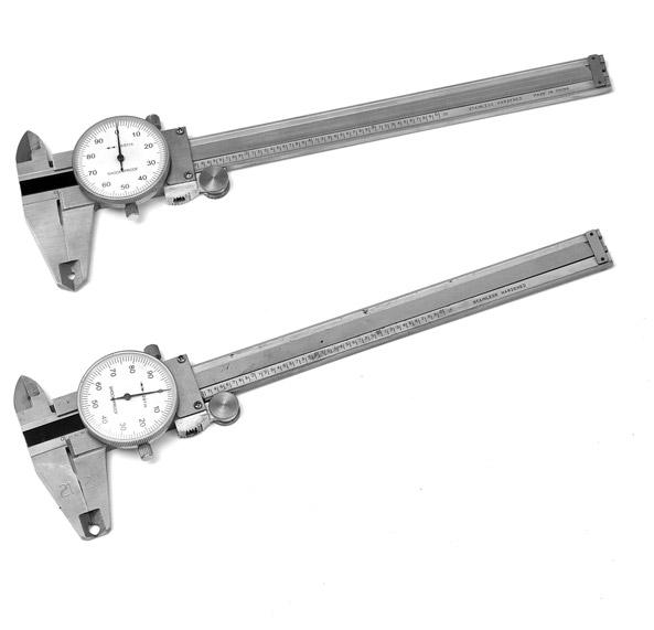
, measure halfway between ridges. (Fig. 1) To be sure crimp diameter is being properly measured, mark a crimp flat. Beginning with that flat, count 9 flats to get the diameter.")
16 MEASURING AND ADJUSTING CRIMP DIAMETERS NOTE: DO NOT measure on top of part number stamps or ridges. 1. Measure crimp diameter. Using Gates calipers (Product No / Part No ), measure halfway between ridges. (Fig. 1) To be sure crimp diameter is being properly measured, mark a crimp flat. Beginning with that flat, count 9 flats to get the diameter. Be sure caliper fingers DO NOT touch ridges or part number stamps. Measure halfway between the ends of the crimped portion of the ferrule. (Fig. 2) 2. Check crimp diameter. The measured crimp diameter must be within 0.010" of the published crimp diameter. Should the actual crimp diameter not be within specified crimp tolerance, the assembly MUST be discarded. 3. Adjust the crimp diameter (if necessary). If crimp diameter is not within specified crimp tolerance, an adjustment to the crimp setting needs to be made. To obtain a smaller crimp diameter, change dial vernier setting to a smaller number. To get a larger crimp diameter, change dial vernier setting to a larger number. Changing the dial vernier number by approximately.02 will change crimp diameter.001". After the correct diameter is achieved, record this new setting in your crimp data manual for future reference. 4. Multiple crimps. When crimping multiple assemblies, check every tenth crimp to ensure diameter is within accept able range (± 0.010"). Discard those outside the specified tolerance.! WARNING : Protect the safety of people using your assemblies! Your measured crimp diameters MUST be in tolerance range as listed in the Gates Crimp Data Manual. 14
.")


17 MAINTENANCE This crimper requires minimal maintenance. However, the following practices are recommended to ensure maximum reliability and service. Flange Head Bolts Every six months, check the torque of the flange head bolts. Torque should be at 330 Nm (2900 in lbs). Lubrication Lubricate sliding surfaces of die cone whenever they become shiny or approximately every 250 crimp cycles. Use Lubrimatic Moly EP Grease or equivalent. Press CRIMP button to close crimper mouth and expose grease fittings. Shut power switch off. Using grease gun, grease both front (8) and back (16) die shoe grease fittings (24 in all) until grease appears on die cone surface. Foam Filler Pads Check every 1000 crimps. If foam pad does not fill space between die shoes, order new set and install. Foam should rebound to original shape when squeezed. Operate crimper through a full CRIMP and RETRACT cycle 5 times to distribute grease evenly. 15


18 MAINTENANCE Check oil level Check hydraulic oil level in pump reservoir after every 10 hours of use. Hydraulic oil should be visible in sight glass. To check oil level, push CRIMP button to fully close crimp head. If oil level drops below the site glass, oil is needed. Change oil and filter (NOTE: Frequency depends on the pump's general working conditions, severity of use, and overall cleanliness.) For general shop conditions, change oil every 300 hours. Change the filter every time you change the oil. Remove cap using a wrench to loosen. Drain, clean and refill reservoir per pump operating instructions with Tellus AW 46 or equivalent. Remove 2-part cap (air filter in top). Add Tellus AW 46 (SAE Grade 46) hydraulic oil or equivalent. 16
19 Die Sets (Includes Tub) Die Set Part No. Product No. Notes L Air Conditioning Air Conditioning Air Conditioning Air Conditioning Power Steering Grease Battery Cable GL GL GL GL GL GL GL Clamp Collar ID Slug Die Finger Finger Number Part No. Product No L CRIMPING TOOLS Die Tooling Supplies Part Product Item No. No. Stainless Steel Dial Caliper 17

20 SCHEMATIC 18
21 REPLACEMENT PARTS LIST Complete GC32-XD Crimper Part No.: Product No.: Includes: Quick Change Tool (QCT), Mirror Foot Pedal Start-up Accessory Tool Kit Part No.: Product No.: Includes: Tube of Grease, Brush, Grease Gun, Dial Calipers, Allen Wrench, Fuses No. Item QTY Product No. Part No. 1 Stand - Die Rack (Optional) not included Die Tubs Die Rack - (Optional) Rack Nuts (4) Rack Bolts (4) Foot Pedal Reservoir Deck screws Back Pressure Control Cartridge Power Unit Replacement Kit (Invertor) Pump bolts Hose Assembly Oil Filter Element Head Seal Breather Cap Breather Element Long Mounting Bolts (Head) Short Mounting Bolts (Head) Pilot Operated Check Relief Valve Valve block adaptor Position 3 Way Solenoid Valve Solenoid Bolts set Outer Washer (Control Panel) O-ring (Control Panel) Inner Washer (Control Panel) Control Panel Replacement Kit Fuses Control Panel Post Quick Change Tool (QCT) Foam Fillers M5x10 Button Cap Screw (Dial Vernier Lock Plate) Dial Vernier Locking Plate Kickers Piston Tubing (Lower) Dial Vernier Piston Adaptor Piston Tubing (Upper) Head Replacement Kit Depth Stop (Optional) Mirror

22 TROUBLE SHOOTING Troubleshooting Guide All equipment is tested for proper performance before it is shipped from the factory. However, if you experience any difficulities, check the list below to help restore equipment to proper operating standards. PROBLEM Pump motor will not start. Setting will not change. CORRECTIONS Check electrical connections. Locking switch may be engaged. Move Switch to left. Red LED on Control Indicates Panel Flashing Solid Rapid Flashing! Crimper is ready Crimper is in the crimping process Problem with electronics in control panel WARNING : Will not hold crimp calibration. Flange head bolts are loose. Check torque of flange bolts to 330 Nm or 2900 in lbs every 6 months of operation. Avoid electrical shock or hydraulic related injury! Disconnect crimper from power source before removing control panel, loosening hydraulic tubing or removing any components. 20

23 ADVANCED TROUBLESHOOTING - LED (Located on printed control board behind Control Panel fascia) 21
24 ADVANCED TROUBLESHOOTING 22
25 ADVANCED TROUBLESHOOTING 23
26 ADVANCED TROUBLESHOOTING 24
27 ADVANCED TROUBLESHOOTING 25
28 ADVANCED TROUBLESHOOTING 26
29 ADVANCED TROUBLESHOOTING 27
30 ADVANCED TROUBLESHOOTING 28
31 ADVANCED TROUBLESHOOTING 29
32 NOTES 30
33 NOTES 31
34 NOTES 32
35 WARRANTY TWO-YEAR LIMITED WARRANTY ON EQUIPMENT For two years from the date of shipment of the equipment to the original user, will, at its option, replace or repair any unit which proves to be defective in material or workmanship, or both, at no cost to the original user of the equipment. This is the exclusive remedy. THERE IS NO OTHER EXPRESS OR IMPLIED WARRANTY. ALL INCLUDING THOSE OF MERCHANTABILITY AND FITNESS FOR A PARTICULAR PURPOSE, ARE LIMITED TO ONE YEAR FROM DATE OF SHIPMENT OF THE EQUIPMENT TO THE ORIGINAL USER. LIABILITY FOR CONSEQUENTIAL AND INCIDENTAL DAMAGES UNDER ANY AND ALL WARRANTIES IS EXCLUDED TO THE EXTENT EXCLUSION IS PERMITTED BY LAW. Some states do not allow the exclusion of incidental or consequential damages, and some states do not allow limitation on how long an implied warranty lasts, so the above limitation and exclusions may not apply to you. This warranty gives you specific legal rights andyou may also have other rights which vary from state to state. For warranty service, contact Service Department,, 1551 Wewatta Street, P.O. Box 5887, Denver, CO For selling prices on inventoried parts, refer to Hydraulic Equipment and Parts List Price Schedule. Selling prices for parts not shown in these lists will be furnished on request, or parts will be shipped at prevailing prices and you will be billed accordingly. For information regarding prices, contact your local Gates representative or, 1551 Wewatta Street, P.O. Box 5887, Denver, CO When returning inoperable equipment, contact your Gates sales representative and request a return goods authorization form. Fill out and send to: Attention: Service Department 1551 Wewatta Street P.O. Box 5887 Denver, Colorado

36 P.O. Box 5887 Denver, CO
OmniCrimp 21. Safety & Operating Manual
 OmniCrimp 21 Safety & Operating Manual WARNING! An incorrect hose assembly can rupture or blow apart in use, resulting in serious injury, death, or property damage. REMEMBER: Others depend on you to make
MC1000 / MC1001 MANUAL. Operating and Calibration Instructions
 MC1000 / MC1001 MANUAL Operating and Calibration Instructions MC1000/MC1001 MANUAL Operating Instructions Contents Certificates.. 3 Circuit Diagram. 5 Gates MC1000/MC1001 Hose Crimping Machine. 6 Operating
CC150 General Production Hose Crimper
 CC0 General Production Hose Crimper The CC0 Series es hose crimper with the Micrometer Style Adjustment t and 0 tons of crimping force has the capability to crimp up to " industrial hose. UNIQUE USER FRIENDLY
MC2000 OPERATING AND CALIBRATION INSTRUCTIONS
 MC2000 OPERATING AND CALIBRATION INSTRUCTIONS CONTENTS 1 - CERTIFICATE OF CONFORMITY... 3 2 - PRESENTATION... 4 2. 1 - GENERAL... 4 2. 2 - CHARACTERISTICS... 4 2. 3 - OPERATING PRINCIPLE... 5 2. 3. 1 -
MC2501 OPERATING AND CALIBRATION INSTRUCTIONS
 MC2501 OPERATING AND CALIBRATION INSTRUCTIONS CONTENTS 1 - CERTIFICATE OF CONFORMITY... 3 2 DESCRIPTION.... 4 2. 1 - GENERAL... 4 2. 2 - CHARACTERISTICS... 4 2. 3 WORKING PRINCIPLE.... 5 2. 3. 1 Hydraulic
KH-80 HYDRAULIC CRIMPER OPERATORS MANUAL
 KH-80 HYDRAULIC CRIMPER OPERATORS MANUAL 1 SAFETY PRECAUTIONS READ AND IDENTIFY ALL COMPONENT PARTS BEFORE USING CRIMPER. CRIMPER CAN PRODUCE 80 TONS OF FORCE. KEEP BOTH HANDS AWAY FROM PINCH POINTS. CONSULT
MobileCrimp Crimper Die Selection Table For MegaCrimp. MobileCrimp. Die Sets (ordered separately) Digital Dial Control
 Digital Dial Control") MobileCrimp 4-20 Crimper This lightweight, versatile crimper is powerful enough to crimp up to 1-1/4" four spiral-wire hose Weighing approximately 57 pounds, this new field crimper combines the latest
MobileCrimp 4-20 Crimper This lightweight, versatile crimper is powerful enough to crimp up to 1-1/4" four spiral-wire hose Weighing approximately 57 pounds, this new field crimper combines the latest
D105M COMPONENT IDENTIFICATION
 D105M COMPONENT IDENTIFICATION 1 35 TON HYDRAULIC CYLINDER REMOVABLE PUSHER OIL FILL AND VENT PLUG PNEUMATIC START/STOP SWITCH 110 VOLT HYDRAULIC PUMP ADJUSTABLE RAM RETRACTION STOP MICRO-CRIMP ADJUSTER
UNIQUE USER FRIENDLY MICROMETER STYLE ADJUSTMENT
 The series hose crimper with Micrometer Style Adjustment and 80 ton cylinder has the capacity to crimp hoses up to 1-¼" 4 wire (with standard dies) and up to 1-¼" 6 wire and 2" 4 wire (with larger dies).
Operator s Manual S-333. Automated Soil Compactor. Version 3.3. Durham Geo Slope Indicator 2175 West Park Court Stone Mountain, GA USA
 Automated Soil Compactor S-333 Operator s Manual Version 3.3 Durham Geo Slope Indicator 2175 West Park Court Stone Mountain, GA 30087 USA Phone: 800-837-0864 or +1.770.465.7557 Fax: 770.465.7447 e-mail:
UNIQUE USER FRIENDLY MICROMETER STYLE ADJUSTMENT
 The series hose crimper with Micrometer Style Adjustment and 62 tons of crimping force has the capability to crimp hoses up -¼" -2 wire, -¼" 4 wire, and " 6 wire. UNIQUE USER FRIENDLY MICROMETER STYLE
Panel Fan Series Operators Manual (Galvanized and Polymer)
") Panel Fan Series Operators Manual (Galvanized and Polymer) 52" Belt Drive, Galvanized Panel Fan with Three Wing Blade IMPORTANT: READ AND SAVE THESE INSTRUCTIONS Read all instructions carefully before
Panel Fan Series Operators Manual (Galvanized and Polymer) 52" Belt Drive, Galvanized Panel Fan with Three Wing Blade IMPORTANT: READ AND SAVE THESE INSTRUCTIONS Read all instructions carefully before
D100S-T420 Portable Service Hose Crimpers
 The D00S-T420 Portable series hose crimper paired with either a ValPower Hand Pump, Pneumatic Pump or Multi-Electric Pump make the perfect combination for portable crimping requirements. UNIQUE USER FRIENDLY
Instruction Manual. Dogeroo, Super Dogeroo, and Mini Dogeroo
 Instruction Manual Dogeroo, Super Dogeroo, and Mini Dogeroo Model No. 8102, 8103, 8108 10700 Medallion Drive, Cincinnati, Ohio 45241-4807 USA Part No. 87793 SAFETY PRECAUTIONS Page 2 INSTALLATION INSTRUCTIONS
D165-D160 SERIES HYDRAULIC HOSE CRIMPER OPERATORS MANUAL
 Page D65-D60 SERIES HYDRAULIC HOSE CRIMPER OPERATORS MANUAL SAFETY PRECAUTIONS Page MODELS COVERED This manual is applicable to different variations of the D60 Series and D65 Series Crimpers. A Standard,
LIMITED LIFETIME WARRANTY
 LIMITED LIFETIME WARRANTY Model No.: F0023 / F0024 aireryder ORIGINAL CEILING FAN LIMITED LIFETIME WARRANTY The limited lifetime warranty covers this ceiling fan, for residential use by the original purchaser,
Safety, Operation and Maintenance Manual with Parts List
 Safety, Operation and Maintenance Manual with Parts List Important Information and Safety Instructions PLEASE READ BEFORE USE! 961130022-10/10-Rev1 TABLE OF CONTENTS Safety Instructions...2 Grounding Instructions...4
OPERATING MANUAL Gfp 255C Please read this manual carefully before operating!
 OPERATING MANUAL Gfp 255C Please read this manual carefully before operating! Unpacking, assembly, and operating videos are available at www.gfpsmoothstart.com 1 Table of Contents Gfp 255C March 2015 Contents
B.I.C.A Built-In Coffee Appliance
 B.I.C.A Built-In Coffee Appliance Automatic Coffee Brewer Parts & Service Models: 1033510, 1033510S & 1033511 3828 S. Main St. Los Angeles, CA 90037-1491 800-421-6860 310-787-5444 Fax 310-787-5412 e-mail:
User s Manual and Operating Instructions
 User s Manual and Operating Instructions Model Numbers: MAC-12F, MAC-20F-DDF, MAC-20FO-DDF, MAC-20S-DDF, MAC-24-DDF, MAC-24P, MAC-24POSC, MAC-24W, MAC-24WOSC, MAC-30W, MAC-30WOSC, MAC-30-DDF, MAC-30P-DDF,
(3 plastic wire connectors,blade balancing kit, 2 extra mounting screws #10-32 for outlet box.)
") Excel Lighting & Manufacturing Ltd. Lifetime Limited Warranty Excel Lighting & Manufacturing Ltd. Warrants the fan motor to be free from defects in workmanship and material present at time of shipment
Excel Lighting & Manufacturing Ltd. Lifetime Limited Warranty Excel Lighting & Manufacturing Ltd. Warrants the fan motor to be free from defects in workmanship and material present at time of shipment
D165 SERIES Service Hose Crimpers
 D65 SERIES Service Hose Crimpers D65 Series hose crimpers with the Micrometer Style Adjustment t and 62 tons of crimping force has the capability to crimp hoses up to " 6SP*. UNIQUE USER FRIENDLY MICROMETER
PANEL FAN SERIES OPERATORS MANUAL (Galvanized and Polymer)
") PANEL FAN SERIES OPERATORS MANUAL (Galvanized and Polymer) Galvanized Panel Fan IMPORTANT: READ AND SAVE THESE INSTRUCTIONS Read all instructions carefully before attempting to assemble, install, operate
PANEL FAN SERIES OPERATORS MANUAL (Galvanized and Polymer) Galvanized Panel Fan IMPORTANT: READ AND SAVE THESE INSTRUCTIONS Read all instructions carefully before attempting to assemble, install, operate
OPERATIONS MAINTENANCE MANUAL
 OPERATIONS MAINTENANCE MANUAL COOK & HOLD OVEN SYSTEMS WITTCO MODEL NUMBERS 1300-AD-SS 1300-AD-SS-SPLIT LIMITED WARRANTY Wittco warrants the Products that it manufactures to be free from defects in materials
CC38 General Production Hose Crimper
 The CC38 Series hose crimper with the Patented t ed ACT Controller and 0 tons of crimping force has the capability to crimp up to " industrial hose. UNIQUE USER FRIENDLY PATENTED ACT TM CONTROLLER Fully
Lifetime Limited Warranty
 Hampton Bay Lifetime Limited Warranty The retailer warrants the fan motor to be free from defects in workmanship and material present at time of shipment from the factory for a lifetime after the date
User s Manual and Operating Instructions
 User s Manual and Operating Instructions Model Numbers: PT-18W-DDF-A, PT-20F-DDF-A, PT-20S-DDF, PT-24O-DDF, PT-24-DDF, PT-24-DDF-F, PT-30-DDF, PT-30P-DDF-A, PT-30P-DDF-AF READ AND SAVE THESE INSTRUCTIONS
Parts and Service Manual BURNISHER MODEL: MR , MR , MR , MR
 Parts and Service Manual BURNISHER MODEL: MR2000-115, MR1500-115, MR2000-220, MR1500-220 TABLE OF CONTENTS RECEIVING YOUR EQUIPMENT... 3 WARNINGS AND SAFETY... 3 ELECTRICAL INFORMATION... 4 GROUNDING INSTRUCTIONS...
Owner & Operator Manual
 Owner & Operator Manual NOTE: FOR ULTIMATE SAFETY AND PERFORMANCE, THIS MANUAL MUST BE READ BY INSTALLATION, OPERATING AND HAULER PERSONNEL, PRIOR TO USE OF EQUIPMENT. 23 Craig Street, Unit #6 Brantford
Swaging Machine Type H50-46ECO
 ENDEAVOUR Int. Ltd. Tel +44 (0) 1225 446770 Fax +44 (0) 1225 446775 USER MANUAL Swaging Machine Type H50-46ECO Website: www.hydralok.net CONTENTS WARRANTY CONDITIONS... 3 EC DECLARATION OF CONFORMITY...
Owner & Operator Manual
 Owner & Operator Manual NOTE: FOR ULTIMATE SAFETY AND PERFORMANCE, THIS MANUAL MUST BE READ BY INSTALLATION, OPERATING AND HAULER PERSONNEL, PRIOR TO USE OF EQUIPMENT. 23 Craig Street, Unit #6 Brantford
OPERATING MANUAL MODEL AIR 1500TM AIR DRYER
 OPERATING MANUAL MODEL AIR 500TM AIR DRYER Puregas, LLC 226-A Commerce St. Tel: 800-52-535 Broomfield, Colorado Fax: 303-657-2205 P/N P0255 REV A, 02/9/4 TABLE OF CONTENTS.0 GENERAL... 3 2.0 SPECIFICATIONS...
Instruction Book for HD Punch Machines
 Instruction Book for HD Punch Machines HD7700, HD7000 & HD7500H Setup & Operator Manual Issue 5 February 2012 Performance Design LLC. These electric punches have been designed to punch most any job that
Instant Hot Water Dispenser Owner s Manual
 Model Hot1 Instant Hot Water Dispenser Owner s Manual Installation, Care & Use Instalacion, cuidado & uso Installation, soin et utilisation WHAT YOU SHOULD KNOW BEFORE YOU BEGIN For your satisfaction and
INSTALLATION USE & CARE MANUAL ALL WEATHER SL-SERIES QUARTZ TUBE ELECTRIC INFRARED RADIANT HEATER
 INSTALLATION USE & CARE MANUAL ALL WEATHER SL-SERIES QUARTZ TUBE ELECTRIC INFRARED RADIANT HEATER TABLE OF CONTENTS IMPORTANT INFORMATION Warnings 2 Installation Instructions 3 Wiring Instructions 3 Outdoor
Glendale 52 in Ceiling Fan Owner's Manual. Glendale Ventilador de Techo de 1.32 m Manual del Propietario
 Glendale 52 in Ceiling Fan Owner's Manual Glendale Ventilador de Techo de 1.32 m Manual del Propietario Hampton Bay Lifetime Motor Warranty The retailer warrants the fan motor to be free from defects in
SERVICE/INSTALLATION MANUAL ICE ONLY DISPENSERS MODELS-IOD150, IOD200 AND IOD250
 SERVICE/INSTALLATION MANUAL ICE ONLY DISPENSERS MODELS-IOD150, IOD200 AND IOD250 Ice-O-Matic 11100 East 45th Ave Denver, Colorado 80239 Part Number 9081305-01 Date 10/08 Introduction IOD150,IOD200,IOD250
1500 RPM BURNISHER. Model P WARNING: OPERATOR MUST READ AND UNDERSTAND THIS MANUAL COMPLETELY BEFORE OPERATING THIS EQUIPMENT.
 OPERATOR S MANUAL & PARTS LIST 1500 RPM BURNISHER Model P1500-3 U.S. Patent Number 4,845,798 U.S. Patent Number 4,756,042 U.S. Patent Number 296,252 WARNING: OPERATOR MUST READ AND UNDERSTAND THIS MANUAL
Bentley II 13 in Ceiling Fan Owner s Manual. Bentley II Ventilador de Techo de 33 cm Manual del Propietario
 Bentley II 13 in Ceiling Fan Owner s Manual Bentley II Ventilador de Techo de 33 cm Manual del Propietario 326 960 Bentley II by Hampton Bay 13 Bentley II Ceiling Fan by Hampton Bay Thank you for purchasing
Food Waste Disposer Instruction Manual
 Food Waste Disposer Instruction Manual See insert for specific information about your new disposer NOTE: IMPORTANT: CAUTION: This Food Waste Disposer has been designed to operate on 110-120 Volt, 60 Hz
HH80C HYDRAULIC CRIMP TOOL
 HH80C HYDRAULIC CRIMP TOOL DATASHEET SEE PAGE 8 FOR IMPORTANT INFORMATION CONCERNING LIMITED WARRANTY, AND LIMITATION OF LIABILITY INTRODUCTION: The HH80C is a hand actuated hydraulic crimp tool designed
INSTALLATION INSTRUCTIONS
 INSTALLATION INSTRUCTIONS BUILT-IN BOTTOM MOUNT REFRIGERATOR/FREEZER DBRTGK72SS-GRILLE KIT (FOR designer SERIES ONLY) VIKING RANGE CORPORATION 111 Front Street Greenwood, Mississippi (MS) 38930 USA (662)
Audi-Larm Audible Alarm
 Audi-Larm Audible Alarm MAINTENANCE AND REPAIR TAL 1706 (L) Rev. 7 MSA 2017 Prnt. Spec. 10000005389(I) Mat. 10093084 Doc. 10093084 REPLACEMENT KITS AND PARTS LIST TAL 1706 (L) Rev. 7-10093084 2 Exploded
User s Manual and Operating Instructions
 User s Manual and Operating Instructions Model Numbers: CL-30P-DDF, CL-20F-DDF, CL-24O-DDF, CL-30-DDF READ AND SAVE THESE INSTRUCTIONS IMPORTANT: Read and understand all of the directions in this manual
AMERICA AMERICA 52 CEILING FAN INSTALLATION AND OPERATION MANUAL
 AMERICA AMERICA 52 CEILING FAN INSTALLATION AND OPERATION MANUAL Ceiling Fan Weight Including Accessories: 21.00 Lbs. READ AND SAVE THESE INSTRUCTIONS TABLE OF CONTENTS Tools and Materials Required...
CC25 HYDRAULIC CRIMPER OPERATORS MANUAL
 CC25 HYDRAULIC CRIMPER OPERATORS MANUAL Page 2 SAFETY PRECAUTIONS READ INSTRUCTIONS AND IDENTIFY ALL COMPONENT PARTS BEFORE USING CRIMPER CRIMPER CAN PRODUCE 137 TONS OF FORCE. KEEP BOTH HANDS AWAY FROM
Industrial Vacuums, Inc
 Instructions/Spare Parts Manual Nilfisk Model GWD255 Drum Top Vacuum CAUTION: This Nilfisk vacuum cleaner is not to be used in explosion-hazardous areas, as serious injury could result. Under no circumstances
OWNERS MANUAL FOR MEC 300E ATA
 OWNERS MANUAL FOR MEC 300E ATA PLEASE READ AND FULLY UNDERSTAND THE INSTRUCTIONS PRIOR TO SETTING OR TUNING THE MACHINE. CAUTION: ANY MEC CLAY TARGET MACHINE MUST BE IN THE DISARMED STATE WITH THE BATTERY
52 CEILING FAN. Owner s Manual Models #50336, 50337
 52 CEILING FAN Owner s Manual Models #50336, 50337 If a problem cannot be remedied or you are experiencing difficulty in installation, please contact the Service Department: 1-877-706-3267, 9 a.m.- 5 p.m.
AUTO SPEED BLENDER INSTRUCTION MANUAL MODEL: BLCLMB1
 AUTO SPEED BLENDER INSTRUCTION MANUAL MODEL: BLCLMB1 1 TABLE OF CONTENTS IMPORTANT SAFEGUARDS 3 POLARIZED PLUG 4 PRODUCT DIAGRAM 5 USAGE INSTRUCTIONS PREPARING YOUR AUTO SPEED BLENDER FOR USE 6 HOW TO
DISHWASHER INSTALLATION GUIDE SPECIFICATIONS, INSTALLATION, AND MORE
 DISHWASHER INSTALLATION GUIDE SPECIFICATIONS, INSTALLATION, AND MORE COVE DISHWASHER Contents 3 Cove Dishwasher 4 Specifications 7 Door Panel 9 Installation 15 Troubleshooting Features and specifications
MKTF CRO-Series 5-Stage Reverse Osmosis System Installation and Maintenance Manual
 MKTF - 215 CRO-Series 5-Stage Reverse Osmosis System Installation and Maintenance Manual Please fill out the following information at the time of installation. Save for future reference. Model: Date Code:
Getz Equipment Innovators 450 lb Dual Portable Dry Chemical Fill System
 Getz Equipment Innovators 450 lb Dual Portable Dry Chemical Fill System 1 Revised 11/18/10 2320 Lakecrest Drive, Pekin IL 61554 PH. (888) 747-4389 Fax (309) 495-0625 Website: www.getzequipment.com LIMITED
CC1000 Production / Industrial Hose Crimper
 The CC000 Series hose crimper with the Patented t ed ACT Controller and 485 tons of crimping force has the capability to crimp hoses from ¼" up to 0" in diameter. UNIQUE USER FRIENDLY PATENTED ACT TM CONTROLLER
Florentine IV 56 in Ceiling Fan Owner s Manual Florentine IV Ventilador de Techo de 1,42 m Manual del Propietario
 Florentine IV 56 in Ceiling Fan Owner s Manual Florentine IV Ventilador de Techo de 1,42 m Manual del Propietario 527-541 Florentine IV by Hampton Bay 56 Florentine IV Ceiling Fan by Hampton Bay Thank
Eldex Column Heater. Operator s Manual
 Eldex Eldex Column Heater Operator s Manual Eldex Laboratories, Inc. 30 Executive Court Napa, CA 94558 Tel: (707) 224-8800 Fax: (707) 224-0688 www.eldex.com Rev. B: 081700 2000Eldex Laboratories, Inc.
Always keep this manual in a safe readily accessible location. MODEL SERIAL SERVICE COMPANY TELEPHONE NUMBER
 Always keep this manual in a safe readily accessible location. MODEL SERIAL SERVICE COMPANY TELEPHONE NUMBER For Operating Instructions or Technical Support Call 1-507-886-6666 Last Revision: 1/31/12 Starting
Eliza Hugger 56 CEILING FAN
 Eliza Hugger 56 CEILING FAN READ AND SAVE THESE INSTRUCTIONS FAN RATING AC 120V. 60Hz Please do not use any electric or battery powered tools in the assembly and installation of this or any Matthews Fan
LIMITED LIFETIME WARRANTY
 LIMITED LIFETIME WARRANTY Model No.: F0003 aireryder ORIGINAL CEILING FAN LIMITED LIFETIME WARRANTY The limited lifetime warranty covers this ceiling fan, for residential use by the original purchaser,
Torrena 42 Ceiling Fan
 Torrena 42 Ceiling Fan Owner s Manual Part # 269268, 269269 Model # 32096, 32097 Exclusively Distributed by: HD Supply Facilities Maintenance, Ltd. Atlanta, GA 30339 2017 Made in China If you are experiencing
Electric Space Heater
 The Choice of Professionals Model No. FUH Series Electric Space Heater Installation & Maintenance Instructions SPECIFICATIONS: FUH 54B Heater Rating and Voltage 5000 W @ 40V 465W @ 40V 333W @ 40V 500W
Warnings 2. Installation Instructions 3. Wiring Instructions 3. Mounting Instructions 4-5. Replacement Element Installation 5. Replacement Parts 5-6
 TABLE OF CONTENTS Warnings 2 Installation Instructions 3 Wiring Instructions 3 Mounting Instructions 4-5 Replacement Element Installation 5 Replacement Parts 5-6 Heater Coverage Areas 6 General Notes 6
52 BERKSHIRE CEILING FAN
 52 BERKSHIRE CEILING FAN Owner s Manual Models #20223, 20224 If a problem cannot be remedied or you are experiencing difficulty in installation, please contact the Service Department: 1-877-459-3267, 9
ET5050 operator's manual
 ET5050 operator's manual Table of contents Page No. Safety instructions 3 Safety decal explanations 4 Specifications 5 Machine setup and installation 5 Environment 6 Height adjustment 6 Filling hydraulic
Roanoke 48 in Ceiling Fan Owner s Manual. Roanoke Ventilador de Techo de 1,22 m Manual del Propietario
 160 854 Roanoke 48 in Ceiling Fan Owner s Manual Roanoke Ventilador de Techo de 1,22 m Manual del Propietario 48 Roanoke Ceiling Fan by Hampton Bay Thank you for purchasing our ceiling fan. This product
ASTRO ENVELOPE FEEDER AMC FOR HEIDELBERG PRINTMASTER INSTALLATION AND OPERATING INSTRUCTIONS
 ASTRO ENVELOPE FEEDER AMC-2000-17 FOR HEIDELBERG PRINTMASTER INSTALLATION AND OPERATING INSTRUCTIONS INTRODUCTION Thank you for purchasing the Astro Envelope Feeder. It is fast, efficient, reliable, and
Lifetime Limited Warranty
 World Imports Lifetime Limited Warranty The retailer warrants the fan motor to be free from defects in workmanship and material present at time of shipment from the factory for a lifetime after the date
Warnings 2. Installation Instructions 3. Wiring Instructions 3. Mounting Instructions 4. Replacement Element Installation 5. Replacement Parts 5
 TABLE OF CONTENTS Warnings 2 Installation Instructions 3 Wiring Instructions 3 Mounting Instructions 4 Replacement Element Installation 5 Replacement Parts 5 Heater Coverage Areas 6 General Notes 6 Maintenance
Camarillo 52 Ceiling Fan
 Owner s Manual Camarillo 52 Ceiling Fan Part # 269263, 269259, 269287 Model # 32091, 32092, 32087 Exclusively Distributed by: HD Supply Facilities Maintenance, Ltd. Atlanta, GA 30339 2017 Made in China
The Extraordinaire OWNER S MANUAL. Orbital Ceiling Fan. Model No. OF110** READ AND SAVE THESE INSTRUCTIONS. Net Weight 14.5 lbs. or 6.59 kg.
 The Extraordinaire Orbital Fan WARNING: Support Directly From Building Structure Net Weight 14.5 lbs. or 6.59 kg. Model No. OF110** OWNER S MANUAL READ AND SAVE THESE INSTRUCTIONS Important Safety Instructions
30-YEAR LIMITED WARRANTY
 PROGRESS LIGHTING 30-YEAR LIMITED WARRANTY PROGRESS LIGHTING FAN MOTORS ARE WARRANTED TO THE END USER TO BE FREE OF ELECTRICAL AND/OR MECHANICAL DEFECTS FOR A PERIOD OF 30 (THIRTY) YEARS FROM DATE OF SALE.
Page 1 of 18. Part# /5/2013
 Part# 1002655-06 8/5/2013 This manual contains important information concerning the installation and operation of the gun washers listed above. Read manual thoroughly and keep for future reference INSTRUCTIONS
READ AND SAVE THESE INSTRUCTIONS READ CAREFULLY BEFORE ATTEMPTING TO ASSEMBLE, INSTALL, OPERATE OR MAINTAIN THE PRODUCT DESCRIBED. PROTECT YOURSELF AN
 READ AND SAVE THESE INSTRUCTIONS READ CAREFULLY BEFORE ATTEMPTING TO ASSEMBLE, INSTALL, OPERATE OR MAINTAIN THE PRODUCT DESCRIBED. PROTECT YOURSELF AND OTHERS BY OBSERVING ALL SAFETY INFORMATION. FAILURE
LIMITED LIFETIME WARRANTY
 LIMITED LIFETIME WARRANTY To obtain Service, please contact or call Turn of the Century Service Department: 1-800-887-6326, 9 a.m.- 5 p.m. central time. Model No.: # 355-6782 The limited lifetime warranty
Manual Parts Washer. Operating Instructions & Warranty Information
 Manual Parts Washer Operating Instructions & Warranty Information Service Line Inc. 2320 Zinga Dr. Reedsburg, WI 53959 1-800-774-7900 Revised 03/24/09 www.renegadepartswashers.com SETTING UP THE RENEGADE
52 SAN LUCAS CEILING FAN
 52 SAN LUCAS CEILING FAN Owner s Manual Models #20551 If a problem cannot be remedied or you are experiencing difficulty in installation, please contact the Service Department: 1-877-459-3267, 9 a.m.-
INSTALLATION INSTRUCTIONS
 INSTALLATION INSTRUCTIONS BUILT-IN BOTTOM MOUNT REFRIGERATOR/FREEZER BRTGK72SS-GRILLE KIT (FOR PROFESSIONAL SERIES ONLY) VIKING RANGE CORPORATION 111 Front Street Greenwood, Mississippi (MS) 38930 USA
Nilfisk Model VHS255 Drum Top Vacuum
 Instructions/Spare Parts Manual Nilfisk Model VHS255 Drum Top Vacuum CAUTION: This Nilfisk vacuum cleaner is not to be used in classified (hazardous) environments, as serious injury could result. Under
DR-180 Through the Wall Exhaust Fan PRODUCT MANUAL & INSTALLATION GUIDE
 DR-180 Through the Exhaust Fan PRODUCT MANUAL & INSTALLATION GUIDE READ AND SAVE THESE INSTRUCTIONS READ CAREFULLY BEFORE ATTEMPTING TO ASSEMBLE, INSTALL, OPERATE OR MAINTAIN THE PRODUCT DESCRIBED. PROTECT
WAILEA OWNER S MANUAL
 WAILEA OWNER S MANUAL The blades in each pack are matched for equal weight to assure smooth fan operation. If more than one fan is being installed, be careful not to mix blades from different cartons.
LIMITED LIFETIME WARRANTY
 LIMITED LIFETIME WARRANTY Model No.: FN52317 aireryder ORIGINAL CEILING FAN LIMITED LIFETIME WARRANTY The limited lifetime warranty covers this ceiling fan, for residential use by the original purchaser,
LIMITED LIFETIME WARRANTY
 LIMITED LIFETIME WARRANTY Model No.: F0030 aireryder ORIGINAL CEILING FAN LIMITED LIFETIME WARRANTY The limited lifetime warranty covers this ceiling fan, for residential use by the original purchaser,
W Model 1RKU2 w/optional Wall mount. Unit Model Weight (Lbs) Kilowatts Volts- Phase Amps Fan Output Heat Output
 Kilowatts Volts- Phase Amps Fan Output Heat Output") Operating Instructions & Parts Manual 1RKT2, 1RKT3, 1RKT4, 1RKT5, 1RKT9 and 1RKU2 Please read and save these instructions. Read carefully before attempting to assemble, install, operate or maintain the
Operating Instructions & Parts Manual 1RKT2, 1RKT3, 1RKT4, 1RKT5, 1RKT9 and 1RKU2 Please read and save these instructions. Read carefully before attempting to assemble, install, operate or maintain the
User Manual. E17/E20 Electric Walk-Behind Scrubber Disc Brush Drive
 User Manual E17/E20 Electric Walk-Behind Scrubber Disc Brush Drive This manual is furnished with each new MINUTEMAN E17/E20. This provides the necessary operating and preventive maintenance instructions.
Panel Fan Series Operators Manual (Galvanized and Polymer)
") Panel Fan Series Operators Manual (Galvanized and Polymer) Galvanized Panel Fan with Three Wing Blade IMPORTANT: READ AND SAVE THESE INSTRUCTIONS Read all instructions carefully before attempting to assemble,
Panel Fan Series Operators Manual (Galvanized and Polymer) Galvanized Panel Fan with Three Wing Blade IMPORTANT: READ AND SAVE THESE INSTRUCTIONS Read all instructions carefully before attempting to assemble,
Ultra Lightweight Household & Commercial Vacuums
 Owner s Manual Ultra Lightweight Household & Commercial Vacuums Save These Instructions Index Important Safety Instructions............................................................. 2 Polarization Instructions................................................................
Hawkins 44 in Ceiling Fan Owner s Manual. Hawkins Ventilador de Techo de 1,12 m Manual del Propietario
 117 391 Hawkins 44 in Ceiling Fan Owner s Manual Hawkins Ventilador de Techo de 1,12 m Manual del Propietario 44 Hawkins Ceiling Fan by Hampton Bay Thank you for purchasing our ceiling fan. This product
PORTABLE HAND POWER THREADER 1/2-2
 PORTABLE HAND POWER THREADER 1/2-2 Read this Operator s Manual carefully before using this tool. Failure to understand and follow the contents of this manual may result in electrical shock, fire and/or
Technical Details. Important Safety Instructions READ ALL INSTRUCTIONS BEFORE USING THIS MACHINE
 SEBO ET-1 Owner's Manual Technical Details Brush motor - 175 watts, 1.6 amps Width: 12 in Weight: 5.4 lbs Brush roller: replaceable Brush drive: toothed belt with electronic overload protection Important
3HP MOBILE CYCLONE DUST COLLECTOR MANUAL FILTER CLEANING MANUAL
 3HP MOBILE CYCLONE DUST COLLECTOR MANUAL FILTER CLEANING MANUAL LAGUNA TOOLS 2072 Alton Parkway Irvine, California 92606 Ph: 800.234.1976 www.lagunatools.com 2018, Laguna Tools, Inc. LAGUNA and the LAGUNA
MANUFACTURING NUMBERS: CORN CAROUSEL. Model CC-19 Series P/N /99. Owner s Manual
 MANUFACTURING NUMBERS: 9500410 9500412 C US Model CC-19 Series 9500400 P/N 1010730 10/99 Owner s Manual A.J. Antunes & Co. Owner Information...1 General...1 Warranty Information...1 Service/Technical Assistance...2
Part No Revised: June TS1 TOASTER SYSTEM Instruction Manual Models # 5700 AND # 5700SF
 Part No. 44162 Revised: June 2006 TS1 TOASTER SYSTEM Instruction Manual Models # 5700 AND # 5700SF SAFETY PRECAUTIONS 2 TOASTER SYSTEM INSTALLATION CHECKING SHIPMENT Unpack the unit from the shipping container
User Manual. Floor Scrubber Traction Drive
 User Manual Floor Scrubber Traction Drive This manual is furnished with each new Floor Scrubber. This provides the necessary operating and preventive maintenance instructions. Operators must read and understand
IMAGE V. Parts and Service Manual
 IMAGE 0V Section II Parts and Service Manual (88B) CLARKE TECHNOLOGY Image Operator's Manual Page AUTHORIZED PERSONNEL MAINTENANCE To Access Pump Motor. Remove brush housing from machine. See "Brush Motor
Bag-In-A-Box Oil System Instruction Manual Model #2257EX & 2257DX For Export Bag-In-Box Pumps Made After March 2003
 Part No. 79431EX Revised: February 2009 Bag-In-A-Box Oil System Instruction Manual Model #2257EX & 2257DX For Export Bag-In-Box Pumps Made After March 2003 Shown Here with Optional 2457S Heated Line Kit.
Technical Data. Name: ERIKA Automat fully automatic machine to divide and to round dough pieces of the same size
 AUTOMAT MANUAL 1 Technical Data Name: ERIKA Automat fully automatic machine to divide and to round dough pieces of the same size Type Divisions Dough Portions (in ounces) Plate Nos. 3 30 1.0 3.5 #35 4/40A
52 CEILING FAN READ AND SAVE THESE INSTRUCTIONS FAN RATING AC 120V.
 Irene 52 CEILING FAN READ AND SAVE THESE INSTRUCTIONS FAN RATING AC 120V. 60Hz TABLE OF CONTENTS Tools and Materials Required... 1 Package Contents... 1 Safety Rules... 2 Mounting Options... 3 Hanging
FES - Series Portable Electric Heaters. YES - Series Suspended Electric Heaters CONTENTS
 FOSTORIA INDUSTRIES, INC. A DIVISION OF FES - Series Portable Electric Heaters YES - Series Suspended Electric Heaters (FES-1524-3E shown) IMPORTANT SAFETY INFORMATION INSIDE Serious injury or death possible.
ALL WEATHER SL-SERIES QUARTZ TUBE ELECTRIC INFRARED RADIANT HEATER INSTALLATION USE & CARE MANUAL
 ALL WEATHER SL-SERIES QUARTZ TUBE ELECTRIC INFRARED RADIANT HEATER TABLE OF CONTENTS: INSTALLATION USE & CARE MANUAL IMPORTANT INFORMATION Assembly Instructions 2 Wiring Instructions 2 Outdoor Installation
Installation Manual. Models 99168, 99169, 99170
 Wet-Rated Globe Fitter Installation Manual Compatible with: 2xxxx Types A - Z 51000-58999 fan series 59500-59999 fan series Select Casablanca Fans Models 99168, 99169, 99170 BEFORE YOU BEGIN Read entire