Solo Plus Units 2001 l a u n a M e ic v r e S
|
|
|
- Leonard Woods
- 6 years ago
- Views:
Transcription


1 Solo Plus Units 2001 S e r v i c e M a n u a l
2
3 PART 1A Wall Mount Units Mod. A B C D E F G SP101LW, SP101HW SP201HW, SP301HW SP201LW, SP401HW SP501HW SP301LW, SP601HW Ceiling Mounted Units J H N I DIMENSIONS MODEL CONDENSER UNIT A x B x C (mm) EVAPORATOR UNIT G x E x F (mm) PLUG SIZE W x H (mm) CUT-OUT SIZE W X H (mm) H x J x K (mm) I x M x N (mm) SP 1 HC 620 x 719 x x 150 x x x 337 SP 2 H & LC 620 x 719 x x 150 x x x 337 SP 3 H & LC 820 x 809 x x 150 x x x 337 SP 4 HC 820 x 809 x x 150 x x x 337 SP 4 LC 820 x 929 x x 220 x x x 458 SP 5 HC 820 x 929 x x 220 x x x 458 1
4 2. SOLO PLUS TECHNICAL DATA STORAGE TEMP +10 C STORAGE TEMP +1/4 C STORAGE TEMP 0/-2 C Foster Ref Qty Capillary Size Foster Ref Qty Capillary Size Foster Ref Qty Capillary Size Model No. Gas Grms No. x Dia x Len Model No. Gas Grms No. x Dia x Len Model No. Gas Grms No. x Dia x Len SP 101HW R404A x 1.5 x 2500 SP 201HW R404A x 1.5 x 2500 SP 301HW R404A x 1.8 x 2000 SP 401HW R404A x 2.0 x 2900 SP 501HW R404A x 1.8 x 2500 SP 601HW R404A x 2.0 x 2000 SP 101HW R404A x 1.5 x 2500 SP 201HW R404A x 1.5 x 2500 SP 301HW R404A x 1.8 x 2000 SP 401HW R404A x 2.0 x 2900 SP 501HW R404A x 1.8 x 2500 SP 601HW R404A x 2.0 x 2000 SP 101HW R404A x 1.5 x 2500 SP 201HW R404A x 1.5 x 2500 SP 301HW R404A x 1.8 x 2000 SP 401HW R404A x 2.0 x 2900 SP 501HW R404A x 1.8 x 2500 SP 601HW R404A x 2.0 x 2000 STORAGE TEMP -18/-21 C Foster Ref Qty Capillary Size Model No. Gas Grms No. x Dia x Len SP 101LW R404A x 1.5 x 2500 SP 201LW R404A x 1.8 x 2500 SP 301LW R404A x 1.6 x 2800 STORAGE TEMP +10 C Foster Nom. HP Cut Out HP Cut In Suction Valve Noise Heat Rejected RoomVent 32 C Ambient 43 C Ambient Air Air Vol Electrical Nominal Defrost Condensate Net Gross Model No. HP Press Bar Press Bar Press Bar Level dba Max 32 C m 3 / h # Watts Room Cap Watts Room Cap Throw mts m 3 / h Volts Phase Hz Amps Watts Type Vaporisation Wt. Kg Wt. Kg SP 101HW Hot Gas Auto SP 201HW Hot Gas Auto SP 301HW Hot Gas Auto SP 401 HW Hot Gas Auto SP 501HW Hot Gas Auto SP 601HW Hot Gas Auto STORAGE TEMP +1/4 C Foster Nom. HP Cut Out HP Cut In Suction Valve Noise Heat Rejected RoomVent 32 C Ambient 43 C Ambient Air Air Vol Electrical Nominal Defrost Condensate Net Gross Model No. HP Press Bar Press Bar Press Bar Level dba Max 32 C m 3 / h # Watts Room Cap Watts Room Cap Throw mts m 3 / h Volts Phase Hz Amps Watts Type Vaporisation Wt. Kg Wt. Kg SP 101HW Hot Gas Auto SP 201HW Hot Gas Auto SP 301HW Hot Gas Auto SP 401 HW Hot Gas Auto SP 501HW Hot Gas Auto SP 601HW Hot Gas Auto STORAGE TEMP 0/-2 C Foster Nom. HP Cut Out HP Cut In Suction Valve Noise Heat Rejected RoomVent 32 C Ambient 43 C Ambient Air Air Vol Electrical Nominal Defrost Condensate Net Gross Model No. HP Press Bar Press Bar Press Bar Level dba Max 32 C m 3 / h # Watts Room Cap Watts Room Cap Throw mts m 3 / h Volts Phase Hz Amps Watts Type Vaporisation Wt. Kg Wt. Kg SP 101HW Hot Gas Auto SP 201HW Hot Gas Auto SP 301HW Hot Gas Auto SP 401 HW Hot Gas Auto SP 501HW Hot Gas Auto SP 601HW Hot Gas Auto STORAGE TEMP -18/-21 C Foster Nom. HP Cut Out HP Cut In Suction Valve Noise Heat Rejected RoomVent 32 C Ambient 43 C Ambient Air Air Vol Electrical Nominal Defrost Condensate Net Gross Model No. HP Press Bar Press Bar Press Bar Level dba Max 32 C m 3 / h # Watts Room Cap Watts Room Cap Throw mts m 3 / h Volts Phase Hz Amps Watts Type Vaporisation Wt. Kg Wt. Kg SP 101LW Hot Gas Auto SP 201LW Hot Gas Auto SP 301LW Hot Gas Auto NOTE: The condenser fan pressure stat fitted on Low Ambient units should be set at 17bar with a 1.5bar differential, this applies to high and low temperature models. 2

5 3. ACCESS TO THE UNIT COMPARTMENT / EVAPORATOR HOUSING WALL MODEL Front Panel: Condenser Fan Assembly: Evaporator Fan Grasp each side of the front panel and pull forward releasing it from the spring clips located down each edge,it may be necessary to separate the front panel from the main body using a flat blade screwdriver and gently ease away. After removing the front panel pull upwards the fan housing assembly releasing it from the 4 spring clips located in each corner, it may be necessary to separate the fan housing assembly from the main body using a flat blade screwdriver and gently ease away. Remove the screw securing the drain tube to the drip tray and remover the drain tube. Remove the four screws securing the drain pan and remove. Remove the three remaining screws securing the side panel and remove it allowing access into the evaporator fan assembly. 4. CONTROLLER OPERATION DESCRIPTION OF ELECTRONIC PANEL
6 1) CONTROL LED (Green): Lit: Compressor running, unit is refrigerating. FLASHING: Compressor is in start delay mode (waiting for signal to start) OFF: Compressor is OFF. Room is down to set temperature. 2) CONTROL LED (Green): LIT: Evaporator fan(s) running. FLASHING: Evaporator fan(s) in start delay mode (waiting for signal to start ) OFF: Evaporator fan (s) OFF 3) Control LED (Yellow): LIT: Unit in defrost mode (auto or manual) Flashing Evaporator drip time with compressor and evaporator fan off. 4) ALARM LED (Red): LIT: Alarm is active see separate ALARMS section. OFF: Unit is functioning normally C 5) DISPLAY: When connected to the mains the display will read OFF indicating the condition of the unit. By pressing the ON/OFF key for 3 seconds the unit will turn ON and display the room temperature. During programming mode the various parameters will be displayed and during alarm mode an alarm code will be displayed. 6) SET/ESC KEY: Pressed for 3 seconds, the led is lit and setting of required room temperature is enabled. During programming it is used to pass from a sub menu to an upper one. 7) DOWN/ ROOM LIGHT KEY: During programming mode or setting of room temperature it serves to reduce the display value. At other times it serves to control the room light. 8) DEFROST/ UP KEY: By pressing for more than 4 seconds it activates a manual defrost. During programming mode or setting of room temperature it serves to increase the displayed value. 9) ON/OFF KEY: To turn the unit ON or OFF press and hold for more than 3 seconds. 10) ENTER KEY: Permits access to the programming menu and passage to the sub menu. Access to this programming mode should be by qualified persons only. 4
7 5
8 6
9 7
10 CONTROLLER ALARMS AND FAULT FINDING. When an alarm condition occurs the unit will display an alarm code ERR (this will differ according to the nature of the alarm): Alarm LED will illuminate (4) Buzzer will sound (if remote alarm is fitted) The alarm relay (for remote alarms) will be energised. The pressing of any key will mute the alarm buzzer. When the alarm is muted the LED will continue to flash for as long as the alarm condition persists. To display the alarm code it is necessary to enter the alarm menu: Press the ENTER key (10) for more than three seconds. FnC will be displayed. Press the DEFROST/UP key (8) until AL is displayed and then press ENTER (10). At this point the alarm code will be displayed indicating the nature of the alarm. High Temperature Alarm (HI) The red LED, buzzer and remote alarm relay are activated; the alarm code HI is displayed in the Alarm Menu. The cause can be: Product to warm Excessive door openings Excessive product load Unit malfunction Low Temperature Alarm (LI) The red LED, buzzer and remote alarm relay are activated; the alarm code LI is displayed in the Alarm Menu. The cause can be: Malfunction of the electronic controller High Pressure Alarm (EO) Each time the pressure switch trips, the buzzer and red LED are activated. If more than ten trips occur during a 1-hour period then the unit will shut down automatically. The remote relay will be activated and the label ERR will flash on the display alternating with the room temperature. The alarm code EO is displayed in the Alarm Menu. The cause can be: Dirty condenser Condenser fan not running Front cover not fitted Obstructed condenser air inlet Obstructed condenser air outlet Inadequate ventilation Voltage Monitor Alarm (E8 only when fitted as an option) The optional voltage monitor is an electronic device that checks the units electrical supply. Should the voltage vary by +/- 12% the unit will shut down for a period of 6 minutes (not adjustable) before attempting to re-start automatically providing the voltage has returned to within limits. The red LED, buzzer and remote alarm relay are activated; the label ERR will flash on the display alternating with the room temperature. The alarm code E8 is displayed in the alarm menu. WARNING: if the Voltage monitor is fitted it is important to note that on start up it has a time delay of seven minutes, during this period the power should be on with the controller in the OFF position. Room Sensor Fault (E1) The red LED, buzzer and remote alarm relay are activated; the label ERR will flash on the display alternating with the room temperature: alarm code E1 in the alarm menu. Possible causes are: Faulty room sensor. Room sensor terminals badly connected. 8
11 Defrost sensor fault (E2) The red LED, buzzer and remote alarm relay are activated; the label ERR will flash on the display alternating with the room temperature: alarm code E2 in the alarm menu. Possible causes are: Faulty defrost sensor Defrost sensor terminals badly connected. Condenser Sensor Fault (4) The red LED, buzzer and remote alarm relay are activated; the label ERR will flash on the display alternating with the room temperature: alarm code E4 in the alarm menu. Possible causes are: Faulty condenser sensor Condenser sensor terminals badly connected. Condenser Temperature Alarm (H4) If the condensing temperature exceeds the factory pre set value (not adjustable) the red LED, buzzer and remote alarm relay are activated: The alarm code H4 is displayed in the alarm menu. Possible causes are: Dirty condenser Condenser fan not running Front cover not fitted Obstructed condenser air inlet TROUBLE SHOOTING 1) Compressor stops. There is an internal over temperature device (Klixon) that stops the compressor each time the admissible temperature of the motor windings is exceeded. Possible causes are: Insufficient ventilation to the compressor Mains voltage anomaly Faulty condenser fan The device will re-set automatically when the windings cool down. 2) Formation of ice on evaporator coil impeding airflow. Possible causes are: Excessive door openings Door left open for long periods Evaporator fan/s faulty Door switch faulty (if fitted) Faulty defrost heater (if fitted) Faulty hot gas solenoid valve (if fitted) Pre set defrost routine not sufficient to clear evaporator of ice build up. Decrease the time interval between defrosts. 3) Display does not illuminate. Is their power to the unit? Is the mains cable connected correctly? Have the fuses in the electrical panel blown? 9
12 7. PARAMETER LIST Medium Label Description Unit of Hot gas Hot gas Range measure defrost defrost dro Display Readout C or F ( 0= C. 1= F) Flag 0 or CA1 Calibration of room sensor C -12 to Compressor re1 menu. cop dif Differential C/ HSE Maximum set point C/1 LSE to LSE Minimum set point C/1-50 to HSE dbi Time delay between 2 compressor starts Minutes 0 to dof Time delay between compressor OFF and next start Minutes 0 to Ont Compressor ON time if room sensor fails Minutes 0 to OFt Compressor OFF time if room sensor fails Minutes 0 to Defrost re2 menu. def dit Time interval between 2 defrosts Hour 0 to det Defrost time override Minutes 1 to dct Defrost interval time count mode Number 0 to = compressor run time 1 = unit run time 2 = each time compressor stops 3 = determined on a real time basis dty Defrost type selection Number 0 to = Timed defrost 1 = Electric defrost 2 = hot gas 3 = Off cycle dt Drain down time Minutes 0 to dst Defrost termination temperature C/1-50 to Evaporator Fans re3 menu. FAn Fdt Fan delay time Minutes 0 to FCO Evaporator fan/s run with compressor Flag n / y n n dfd Fan/s stops during defrost Flag n / y y y Fod Fan/s off when door opened Flag on/off on on FSt Fan stop temperature C/1-50 to Room Light re4 menu. LUc No parameters Temperature Alarms re5 menu. ALP LAL Low temperature alarm C/1-50 to HAL -5-5 HAL High temperature alarm C/1 LAL to AFd Alarm differential C/1-12 to PAO Alarm delay after start-up Hour 0 to dao Alarm delay after defrost Minutes 0 to OAO Alarm delay after door opening Hour 0 to Pressure alarms re6 menu. PP PEi Time period for pressure trips Minutes 1 to Pen Numbers of pressure trips Number 0 to Condensing temperature alarms re7 menu. ALP HAL Maximum condensing temperature alarm setpoint C/1 0 to AFd Alarm differential C/1-12 to Low 10
13 8. ELECTRICAL CONNECTIONS The unit operates from a 220/240v1-50hz or a 400v- 3-50hz electrical supply as denoted in the technical data. For 60hz application consult Foster. The selection of mains cable depends on the unit (Amps) and on the siting of the cable itself. The installer will therefore evaluate the most suitable one on a case by case basis. The table below gives a rough sizing and should be used as a guide only Unit Amps Cable diameter Up to 12 Amps 1.5mm 2 12 to 17 Amps 2.5mm 2 Over 17 Amps 4mm 2 Remove the front panel of the unit and connect the cables to the terminal box as per the diagrams in fig 1,2,3 and 4. Mains Supply Cable BR L 1 BL YG N PE Single Phase Unit L1 Brown N Blue PE yellow / green L 1 N PE Fig 1. Mains Supply Cable BR BLK BL YG L 1 L 2 L 3 N PE 230V/ three phase unit without neutral. L1 Brown L2 Black L3 Blue PE yellow / green L 1 L 2 L 3 N PE Fig 2. Mains Supply Cable BR BLK BLK BL YG L 1 L 2 L 3 N PE 400V/ three phase unit with neutral. L1 Brown L2 Black N Blue L3 Black PE yellow / green L 1 L 2 L 3 N PE Fig 3. Door Microswitch Door Heater Remote Alarm Cable BR 1 1 BL 2 2 BR 3 3 BL 4 4 GV BR 5 5 BL 6 6 Fig 4. Connections for options 1 = Brown 5 = Brown 2 = Blue 6 = Blue 3 = Brown 4 = Blue = yellow/green 11
14 9. PROBE RESISTANCE VALUES The air and defrost probes have the following temperature resistance values (K ohms) Temperature Kohms Temperature Kohms +50 C 4,161 0 C 27, C 5, C 42, C 8, C 67, C 12, C 111, C 17, C 188, FUSE RATINGS FOSTER CODE Internal fuse Wiring diagram SP101HW 16 A J1018 SP201HW 16 A J1018 SP301HW 20 A J1018 SP401HW 25 A J1018 SP501HW No fuses J2020 SP601HW No fuses J2019 SP101LW 20 A J1018 SP201LW No fuses J2019 SP301LW No fuses J2019 SP101HW LA 16 A J1019 SP201HW LA 16 A J1019 SP301HW LA 20 A J1019 SP401HW LA 25 A J1019 SP501HW LA No fuses J2021 SP601HW LA No fuses J2022 SP101LW LA 20 A J1019 SP201LW LA No fuses J2022 SP301LW LA No fuses J2022 NOTE: LA refers to Low Ambient Models 12
15 11. WIRING DIAGRAMS COMPONENT IDENTIFICATION BA ROOM SENSOR FTE EMERGENCY STAT BC CONDENSER ALARM SENSOR HI ALARM BS DEFROST SENSOR K1 CONTACTOR BVR SPEED REGULATOR K11 DEFROST CONTACTOR BVRS SPEED REGULATOR SENSOR M1 COMPRESSOR MOTOR Nr.1 E DEFROST HEATER MPC DOOR MICROSWITCH(ROOM) E1 RESISTENZA CARTER COMPRESSORE MVC CONDENSER FAN MOTOR M1 COMPRESSOR CRANKCASE HEATER MVE EVAPORATOR FAN MOTOR EP DOOR HEATER CIRCUIT P1MX COND. FAN STARTING PRESSURE SWITCH ER1 CONTROL BOARD HEATER PMI L/P SWITCH ER2 VOLTAGE REGULATOR HEATER PMX H/P SWITCH ES CONDENSATE DRAIN HEATER Q1 MAIN SWITCH F13 VOLTAGE REGULATOR FUSE Q3 COND. FAN SPEED REGULATOR OFF SWITCH F1 COMPRESSOR FUSE T TRANSFORMER F1E ELECTRONIC CONTROL CAB X TERMINAL BOARD-CONNECTOR F20 AUXILIARY FUSE YG REFRIGERANT SOLENOID FL ROOM LIGHT FUSE YS HOT GAS SOLENOID FM VOLTAGE REGULATOR 13
16 Colour Code MA - BROWN BL - BLUE GV - GREEN/YELLOW NE - BLACK SUPPLY 400V/3N-/50Hz FOSTER REFRIGERATOR - A Division of ITW Ltd. Title SP501HW Drawing No. Sheet No. J of 1 Drawn By Approved Date 14
17 SUPPLY V/1N-/50Hz Colour Code MA - BROWN BL - BLUE GV - GREEN/YELLOW NE - BLACK LOW TEMP ONLY FOSTER REFRIGERATOR - A Division of ITW Ltd. Title SP101LW SP101HW SP201HW SP301HW SP101LW SPE Drawing No. Sheet No. J of 1 Drawn By Approved Date 15
18 Colour Code MA - BROWN BL - BLUE GV - GREEN/YELLOW NE - BLACK SUPPLY 400V/3N-/50Hz FOSTER REFRIGERATOR - A Division of ITW Ltd. Title SP201LW SP301LW SP601HW Drawing No. Sheet No. J of 1 Drawn By Approved Date 16
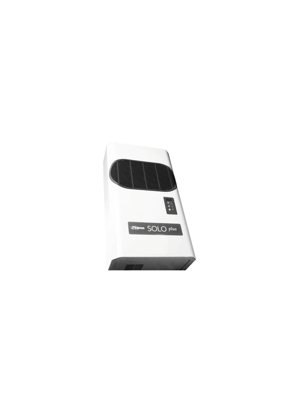
19 PART 1B Ceiling Mounted Solo January 2003 Controller Settings Dimensions A B C D E F G H I L M X Y SP1/SP SP3/SP SP Description 1. Condensing unit and Evaporator (evaporator plaed in an insulated box) located outside of the coldroom. 2. Air inlet and outlet to the evaporator located inside the coldroom. 3. Electrical control panel located in the condensing unit enclosure. 4. Wall mounted control panel. 17
20 WALL MOUNT SOLO PLUS TECHNICAL DATA STORAGE TEMP +10 C STORAGE TEMP +1/4 C STORAGE TEMP 0/-2 C Foster Ref Qty Capillary Size Foster Ref Qty Capillary Size Foster Ref Qty Capillary Size Model No. Gas Grms No. x Dia x Len Model No. Gas Grms No. x Dia x Len Model No. Gas Grms No. x Dia x Len SP 1HC R404A x 1.63 x 2200 SP 2HC R404A x 1.83 x 3100 SP 3HC R404A x 1.38 x 3100 SP 4HC R404A x 1.98 x 2900 SP 5HC R404A x 1.98 x 2000 SP 1HC R404A x 1.63 x 2200 SP 2HC R404A x 1.83 x 3100 SP 3HC R404A x 1.38 x 3100 SP 4HC R404A x 1.98 x 2900 SP 5HC R404A x 1.98 x 2000 SP 1HC R404A x 1.63 x 2200 SP 2HC R404A x 1.83 x 3100 SP 3HC R404A x 1.38 x 3100 SP 4HC R404A x 1.98 x 2900 SP 5HC R404A x 1.98 x 2000 STORAGE TEMP -18/-21 C Foster Ref Qty Capillary Size Model No. Gas Grms No. x Dia x Len SP 1LC R404A x 1.49 x 1900 SP 2LC R404A x 1.98 x 3000 SP 3LC R404A x 1.63 x 2900 STORAGE TEMP +10 C Foster Nom. HP Cut Out HP Cut In Suction Valve Noise Heat Rejected RoomVent 32 C Ambient 43 C Ambient Air Air Vol Electrical Nominal Defrost Condensate Net Gross Model No. HP Press Bar Press Bar Press Bar Level dba Max 32 C m 3 / h # Watts Room Cap Watts Room Cap Throw mts m 3 / h Volts Phase Hz Amps Watts Type Vaporisation Wt. Kg Wt. Kg SP 1HC Hot Gas Auto SP 2HC Hot Gas Auto SP 3HC Hot Gas Auto SP 4HC Hot Gas Auto SP 5HC Hot Gas Auto STORAGE TEMP +1/4 C Foster Nom. HP Cut Out HP Cut In Suction Valve Noise Heat Rejected RoomVent 32 C Ambient 43 C Ambient Air Air Vol Electrical Nominal Defrost Condensate Net Gross Model No. HP Press Bar Press Bar Press Bar Level dba Max 32 C m 3 / h # Watts Room Cap Watts Room Cap Throw mts m 3 / h Volts Phase Hz Amps Watts Type Vaporisation Wt. Kg Wt. Kg SP 1HC Hot Gas Auto SP 2HC Hot Gas Auto SP 3HC Hot Gas Auto SP 4HC Hot Gas Auto SP 5HC Hot Gas Auto STORAGE TEMP 0/-2 C Foster Nom. HP Cut Out HP Cut In Suction Valve Noise Heat Rejected RoomVent 32 C Ambient 43 C Ambient Air Air Vol Electrical Nominal Defrost Condensate Net Gross Model No. HP Press Bar Press Bar Press Bar Level dba Max 32 C m 3 / h # Watts Room Cap Watts Room Cap Throw mts m 3 / h Volts Phase Hz Amps Watts Type Vaporisation Wt. Kg Wt. Kg SP 1HC Hot Gas Auto SP 2HC Hot Gas Auto SP 3HC Hot Gas Auto SP 4HC Hot Gas Auto SP 5HC Hot Gas Auto STORAGE TEMP -18/-21 C Foster Nom. HP Cut Out HP Cut In Suction Valve Noise Heat Rejected RoomVent 32 C Ambient 43 C Ambient Air Air Vol Electrical Nominal Defrost Condensate Net Gross Model No. HP Press Bar Press Bar Press Bar Level dba Max 32 C m 3 / h # Watts Room Cap Watts Room Cap Throw mts m 3 / h Volts Phase Hz Amps Watts Type Vaporisation Wt. Kg Wt. Kg SP 2LC Hot Gas Auto SP 3LC Hot Gas Auto SP 4LC Hot Gas Auto NOTE: Noise levels taken in a room with a concrete floor, no sound attenuation and ceiling height of 7 metres with the unit base 1.5 metres from floor level, installed in a coldroom and the Sound Metre 3 metres distance. 18
21 1) Control LED (GREEN) ON: Compressor running, unit refrigerating. FLASHING: Compressor is in Start Delay mode. OFF: Compressor off, Room down to temperature 2. Control LED (GREEN) ON: Evaporator fan running. FLASHING: Evaporator fan in start delay mode. OFF: Evaporator fan off. Unit in defrost mode. 3. Control LED (YELLOW) ON: Unit in Automatic or Manual defrost. 4. Alarm LED (RED) ON: Alarm activated due to Sensor failure, pressure switch intervention or coldroom temperature outside set values. OFF: Unit operating normally. 5. DISPLAY: On connection to the main supply OFF is displayed indicating the statues of the unit. By pressing the ON/OFF key for 3 seconds the unit is turned on with the room temperature displayed. In the programming mode the parameters are displayed and if an alarm occurs the code is displayed. 6. SET key: When pressed for two seconds it illuminates and allows the room temperature to be set. During programming it is used to pass from submenu to an upper menu. 7. DOWN/ROOM LIGHT key: In programming mode or when setting room temperature it is used to reduce the displayed value. At other times it is used to turn the coldroom light on or off. 8. MANUAL DEFROST/UP key: In programming mode or when settings room temperature it is used to increase the displayed value. Manual defrost initiated if pressed for more then 5 seconds. 19
22 9. ON/OFF key: When pressed for 2 seconds it turns the unit off or on. 10. ENTER key: Allows access to the menu and submenus. Access to the programming mode should only be attempted after reading and fully understanding the service manual, as inserting incorrect information will effect the operation of the unit. ROOM TEMPERATURE SETTINGS. Set the required room temperature. With the unit in normal operating mode press the SET key to display the set temperature. To change the value press either the UP/DEFROST key or the DOWN/INTERIOR LIGHT key. Once you have reached the desired setting press SET key to confirm and store the change. INSTRUCTION FOR PARAMETER MODIFICATION ACCESSING THE PARAMETERS Press and hold the ENTER key 00 will be displayed. for 5 seconds. Press the UP/DEFROST key till it displays 22 The first parameter to be changed will be displayed. Press the UP/DEFROST key or the DOWN/INTERIOR LIGHT key to scroll through the parameters. Press the SET key to display the value of the parameter selected. To change the value press either the UP/DEFROST key until you reach the new value. or the DOWN/INTERIOR LIGHT key 20
23 Press the SET key to display the value of the parameter selected. To change the value press either the UP/DEFROST key until you reach the new value. or the DOWN/INTERIOR LIGHT key Press the SET key to confirm the value. Repeat the operation to modify the required parameters. To memorise the new values and exit the parameters press the ENTER key. NOTE: If you do not press the ENTER key the new values will not be memorised. If no buttons are pressed for 60 seconds the controller will revert to normal operation. 21
24 22
25 PROBE RESISTANCE VALUES The air and defrost probes have the following temperature resistance values (K ohms) Temperature Kohms Temperature Kohms +50 C 4,161 0 C 27, C 5, C42, C 8, C67, C 12, C111, C 17, C188,400 FUSE RATINGS FOSTER CODE INTERNAL FUSE VOLTAGE WIRING DIAGRAM SP1HC 16 A 230/1/ LSB SP2HC 20 A 230/1/ LSB SP3HC 20 A 230/1/ LSB SP4HC 10 A 400/3/ LSB SP5HC 16A 400/3/ LSB SP2LC 20A 230/1/ LSB SP3LC 16A 400/3/ LSB SP4LC 16A 400/3/ LSB CONTROLLER ALARMS AND FAULT FINDING When an alarm condition occurs the unit will display an alarm code ERR (this will differ according to the nature of the alarm): High Temperature Alarm. In the event of a high temperature alarm, HI and the room temperature will be displayed alternately. Possible cause: To frequent door openings. The product load in the room exceeds the room capacity. The temperature of the product stored in the room is too high. Refrigeration system malfunction. Low Temperature Alarm. In the event of a high temperature alarm, LO and the room temperature will be displayed alternately. Possible cause: Faulty PCB. Room Temperature Probe Alarm. In the event of a room temperature probe alarm, E0 will be displayed. Room temperature probe not connected correctly. Faulty probe. Evaporator Probe Alarm. In the event of a room temperature probe alarm, E1 will be displayed. Evaporator probe not connected correctly. Faulty probe. 23
26 High Pressure Alarm (HH) Each time the pressure switch trips, the buzzer and red LED are activated. If more than ten trips occur during a 1-hour period then the unit will shut down automatically. The remote relay will be activated and the label ERR will flash on the display alternating with the room temperature. The alarm code EO is displayed in the Alarm Menu. The cause can be: Dirty condenser Condenser fan not running Front cover not fitted Obstructed condenser air inlet Obstructed condenser air outlet Inadequate ventilation TROUBLE SHOOTING 1) Compressor stops. There is an internal over temperature device (Klixon) that stops the compressor each time the admissible temperature of the motor windings is exceeded. Possible causes are: Insufficient ventilation to the compressor Mains voltage anomaly Faulty condenser fan The device will re-set automatically when the windings cool down. 2) Formation of ice on evaporator coil impeding airflow. Possible causes are: Excessive door openings Door left open for long periods Evaporator fan/s faulty Door switch faulty (if fitted) Faulty defrost heater (if fitted) Faulty hot gas solenoid valve (if fitted) Pre set defrost routine not sufficient to clear evaporator of ice build up. Decrease the time interval between defrosts. 3) Display does not illuminate. Is their power to the unit? Is the mains cable connected correctly? Have the fuses in the electrical panel blown? 24
27 Colour Code MA - BROWN BL - BLUE GV - GREEN/YELLOW NE - BLACK FOSTER REFRIGERATOR - A Division of ITW Ltd. Title SP3LC SP4LC SP4HC SP5HC Drawing No. Sheet No LSB 1 of 1 Drawn By Approved Date 25
28 Colour Code MA - BROWN BL - BLUE GV - GREEN/YELLOW NE - BLACK FOSTER REFRIGERATOR - A Division of ITW Ltd. Title SP1C SP1HC SPE SP2HC SP2LC SP3HC SP3HC SPE Drawing No. Sheet No LSB 1 of 1 Drawn By Approved Date 26

29 SOLO PLUS Service Manual 27
30 WALL MOUNTED UNITS AIR FLOW DIRECTION Wall mounted C D E A D=100mm Ceiling mounted WG 1 a + b + c CEILING MOUNTED UNITS J H N I Solo Plus 3D DRWG 2 DIMENSIONS MODEL CONDENSER UNIT A x B x C (mm) EVAPORATOR UNIT G x E x F (mm) PLUG SIZE W x H (mm) CUT-OUT SIZE W X H (mm) H x J x K (mm) I x M x N (mm) SP 1 H & LW 454 x 735 x x 420 x x x 305 SP 2 H & LW 454 x 735 x x 420 x x x 305 SP 3 H & LW 754 x 735 x x 420 x x x 305 SP 4 HW 754 x 735 x x 420 x x x 305 SP 4 LW 754 x 840 x x 580 x x x 475 SP 5 H & LW 754 x 840 x x 580 x x x 475 SP 1 HC 620 x 719 x x 150 x x x 337 SP 2 H & LC 620 x 719 x x 150 x x x 337 SP 3 H & LC 820 x 809 x x 150 x x x 337 SP 4 HC 820 x 809 x x 150 x x x 337 SP 4 LC 820 x 929 x x 220 x x x 458 SP 5 HC 820 x 929 x x 220 x x x 458 NOTE: W = wall mounted unit. C = ceiling mounted unit 28
31 SOLO PLUS REFRIGERATION SYSTEM CONTENTS PAGE INTRODUCTION Introduction 23 Solo Plus is a range of packaged refrigeration systems comprising of 10 Wall Models and 8 Technical Data 24 Ceiling Models. The systems are pre-charged with refrigerant and Access 25 pre-wired ready for installation into a coldroom with only electrical connections to be made. No external Controller Operation drain is required. Units will operate up to 43 C ambient conditions Controller Parameters (ISO Climate Class 5). If installed outside neither the coldroom or the Solo is weatherproof, therefore Controller Inputs / Outputs 34 suitable protection must be provided. Probe Resistance Values 34 Electrical Connections 35 Fuses 36 Table 1. Storage Conditions C Unit Type Refrigerator Meat Freezer Controller Fault Finding 37 Temp /+4 0/-2-18/21-25 Model SP1HW SP1HW SP1HW SP1LW Controller Emergency Repair 38 SP2HW SP2HW SP2HW SP2LW SP2LW SP3HW SP3HW SP3HW SP3LW SP3LW Routine Maintenance 38 SP4HW SP4HW SP4HW SP4LW SP4LW Wiring Diagrams SP5HW SP5HW SP5HW SP5LW SP5LW SP1HC SP1HC SP1HC SP2HC SP2HC SP2HC SP2LC SP2LC SP3HC SP3HC SP3HC SP3LC SP3LC SP4HC SP4HC SP4HC SP4LC SP4LC SP5HC SP5HC SP5HC NOTE! Nomenclature W refers to Wall Model and C to Ceiling model. As each model operates at different temperatures it will be necessary to set required operating Temperature. See Operating and Installation Manual. 29
32 SOLO PLUS TECHNICAL DATA Foster Refrigerant Qty Nom. HP Cut Out HP Cut In Suction Valve Noise Heat Rejected Room Vent. 32 C Amb. Room 43 C Amb. Room Air Air Vol Electrical Nominal Defrost Condensate Net Gross Model No. Gms HP Press Bar Press Bar Press Bar Level dba Max 32 C m 3 / h # Duty Watts Cap. m 3 Duty Watts Cap. m 3 Throw m m 3 / h Volts Phase Hz Amps Watts Type Vaporisation Wt. Kg Wt. Kg STORAGE TEMP +10 C SP 1HW R 404a Hot Gas Auto SP 2HW R 404a HG Auto SP 3HW R 404a HG Auto SP 4HW R 404a HG Auto SP 5HW R 404a HG Auto STORAGE TEMP +1/+4 C SP1HW R 404a HG Auto SP 2HW R 404a HG Auto SP 3HW R 404a HG Auto SP 4HW R 404a HG Auto SP 5HW R 404a HG Auto STORAGE TEMP 0/-2 C SP 1HW R 404a HG Auto SP 2HW R 404a HG Auto SP 3HW R 404a HG Auto SP 4HW R 404a HG Auto STORAGE SP 5HW TEMP R-404a -18/-21 C HG Auto SP 1LW R 404a HG Auto SP 2LW R 404a HG Auto SP 3LW R 404a HG Auto SP 4LW R 404a HG Auto SP 5LW R 404a HG Auto STORAGE TEMP -25 C SP 2LW R 404a HG Auto SP 3LW R 404a HG Auto SP 4LW R 404a HG Auto SP 5LW R 404a HG Auto STORAGE TEMP +10 C SP 1HC R 404a HG Auto SP 2HC R 404a HG Auto SP 3HC R 404a HG Auto SP 4HC R 404a HG Auto SP 5HC R 404a HG Auto STORAGE TEMP +1/+ 4 C SP 1HC R 404a HG Auto SP 2HC R 404a HG Auto SP 3HC R 404a HG Auto SP 4HC R 404a HG Auto SP 5HC R 404a HG Auto STORAGE TEMP 0/-2 C SP 1HC R 404a HG Auto SP 2HC R 404a HG Auto SP 3HC R 404a HG Auto SP 4HC R 404a HG Auto SP 5HC R 404a HG Auto STORAGE TEMP -18/-21 C SP 2LC R 404a HG Auto SP 3LC R 404a HG Auto SP 4LC R 404a HG Auto STORAGE TEMP -25 C SP 2LC R 404a HG Auto SP 3LC R 404a HG Auto SP 4LC R 404a HG Auto NOTE: Noise levels taken in a room with a concrete floor, no sound attenuation and ceiling height of 7 metres with the unit base 1.5 metres from floor level, installed in a coldroom and the Sound Meter 3 metres distance. # Room Ventilation requirements if the Solo is installed in a confined area. Solo 10.wk4.mgr Revised
33 ACCESS TO THE UNIT COMPARTMENT / EVAPORATOR HOUSING WALL MODEL Front Panel: Remove the 2 fixing screws located under the base of the front panel and pull forward releasing it from the 4 spring clips located in each corner. Condenser Fan After removing the front panel pull upwards the fan housing assembly releasing it from the 4 Assembly: spring clips located in each corner. Evaporator Remove the 4 fixing screws from holding the drain pan in position and the side panel fixing screws. Assembly: Take the panel allowing access into the evaporator fan assembly. CEILING MODEL Unit Housing: Remove the 4 fixing screws from the front panel and pull upwards to release it from the 2 spring clips located at the top. Evaporator Assembly: Remove the 4 fixing screws from the fan plate and lower allowing access to the evaporator fan motor and the evaporator assembly. CONTROLLER OPERATION DESCRIPTION OF ELECTRONIC PANEL ) COMPRESSOR LED (Green) LIT: the compressor is running. The unit is cooling. FLASHING: the compressor is in a delayed start mode OFF: the compressor is OFF. The required room temperature has been reached. 2) EVAPORATOR FAN LED (Green) LIT: evaporator fan is running. FLASHING: the evaporator fan is in a delayed start mode OFF: the evaporator fan is OFF. Unit in defrost mode. 3) DEFROST LED (Yellow) LIT: automatic or manual defrost in progress. 4) ALARM LED (Red) LIT: alarm mode: malfunctioning of a sensor, or intervention of pressure-stat or room temperature outside preset limits. OFF: unit working normally. 31
34 5) DISPLAY When the machine is not in operation, the label OFF and the cell temperature are intermittently displayed one after the other on the digital display. When the machine is in operation, during the normal working cycle, the display indicates the room temperature. Parameters being set will be displayed during programming. A Fault Code will be displayed during an alarm mode. 6) SET KEY - Permits entry of room temperature requirements. 7) DOWN KEY - Key to decrease data values. 8) MAN.DEF./UP KEY - Key to increase data values Press for 8 seconds at least to initiate manual defrost as well. 9) KEY T.A.A. - Key to mute audible alarm This alarm is not fitted as standard to the unit but can be added by the client. To connect use the free terminals 1 & 2 (volt free) on the internal electronic panel. Terminal 2 should have a live feed brought to it. 10) ON/OFF KEY - Main switch 11) LAMP KEY - Push to turn room lamp ON/OFF. A red LED lights when lamp is ON. ROOM TEMPERATURE SETTING With the unit in normal operating mode, the only active keys are ON/OFF (10) and LAMP (11). The latter is always operative except when in programming mode. Room temperature programming: - Press key (10) to turn ON unit. The actual room temperature will be shown on the display (5). In this condition the unit is ready for programming. It is necessary therefore to set the required room temperature bearing in mind the limits of the range which the unit is able to operate. Minimum Temp Maximum Temp Recommended Temp H Range - 5 C + 10 C General Purpose + 3 C Chilled + 1 C Fresh Meat - 2 C L Range -25 C - 15 C - 21 C - Press the SET key (6) (the yellow LED will light). The last set temperature will be displayed on the display screen (5) which shows the set value. - Press the SET key (6), the yellowled will light for one second and the display (5) will start flashing a few seconds later, indicating the set temperature. If you wish to change the setting, use the following keys: (8) to raise set temperature (7) to lower set temperature Once the required setting is displayed, press the SET key (6) to confirm. The unit is now fully operational and no other programming is required. The refrigerating cycle is fully automatic according to factory-set parameters, that can eventually be modified by authorised personnel only. 32
35 INSTRUCTIONS FOR PARAMETER MODIFICATION 1. HOW TO SET THE PARAMETERS: 1A. Keep the keys and pressed together for more than 5 seconds. 1B. 00 will be displayed. 1C. Press the key to display 22 (password) 1D. Confirm with 1E. The first parameter to be changed will be displayed. To modify parameters see next section Parameters modification. 2. PARAMETER MODIFICATION: To modify a parameter please follow the instruction given here under: 2A. Press or to display the parameter of which you want modify the value (see user parameters). 2B. Press the key to display the value connected to the parameter. 2C. Modify the value pressing and until you reach the required one. 2D. Press the key to confirm temporarily the new value and return to the display of the parameter code. 2E. Repeat every operation code from point 2A in order to modify the other parameters values. 3. MEMORISATION OF NEW VALUES: To modify a parameter please follow the instruction given here under: 3A. Press the key to memorise all the new values and exit the parameter modification proceedure. TO EXIT WITHOUT MODIFYING PARAMETERS: do not press any key for at least 60 seconds. (exit for TIME OUT). ATTENTION: If you do not press the key after the parameter changes, all modifications selected will be lost. 33
36 PARAMETERS DESCRIPTION TEMPERATURE PROBE SETTING C: CALIBRATION It allows to add an offset to the measured value. It is active only with the air probe, while the evaporator probe cannot be calibrated. 2: DIGITAL FILTER It allows to define the coefficient used in the digital filter of the measured value. High values for this parameter allow to reduce the noise present in the input lines (but the measure operation is slower). The suggested value is 4. 3: INPUT LIMITATION It allows to define the maximum range of the measure in a machine cycle. Low values of the parameter allow to threshold the maximum variation of the measure, removing impulsive noise or spikes. The suggested value is 8. 4: VIRTUAL PROBE The value used for regulation is an average of the value measured by the temperature probe and of the value measured by the defrost probe. 5: CELSIUS / FAHRENHEIT It allows to choose the operating temperature scale. 6: DECIMAL POINT It allows to enable the decimal point in the range -9.9 to (0=No, 1=YES). rd: REGULATION DELTA It defines the temperature differential used in the temperature set-point. r1: MINIMUM SET ALLOWED Defines the lower value when tuning the set-point of the device. r2: MAXIMUM SET ALLOWED Defines the upper value when tuning the set-point of the device. r3: DIRECT/REVERSE Enables or disables the Ed alarm display (defrost stopped for time-out). The alarm is handled anyway to allow the supervisor to defect it. r4: CURTAIN SET-POINT DELTA It defines the variation of the set-point when operating with the curtain closed. r5: MAXIMUM AND MINIMUM ENABLE It enables or disables the display of the air probe maximum value rh and of the minimum value rl measured in the tr time. rt: MONITORING INTERVAL It defines, in hours, the temperature monitoring time interval during which the parameters rh and rl are updated. During the rt parameter display, pressing the down key it is possible to force a timer reset, setting automatically rh = rl = Temperature. rh e rl parameters reset occurs also when rt timer reaches its maximum value. rh: MAXIMUM TEMPERATURE MEASURED DURING RT Shows the maximum temperature measured by the air probe during the time interval rt. 34
37 rl: MINIMUM TEMPERATURE MEASURED DURING rt. Shows the minimum temperature measured by the air probe during the time interval rt. C0: DELAY AFTER RESET It delays the compressor and fan activation after the power on of the device, so to dispose the power consumption. It also protects the compressor against repeated activations in case of power loss. During the delay after reset the compressor LED blinks if the compressor should be activated. During this interval the fan LED also blinks. c1: MINIMUM TIME BETWEEN TWO COMPRESSORS POWER-ONs It defines the minimum time pass between two compressor activations (it also defines the number of activations per hour). The start delay after reset is defined by the previous parameter. c2: OFF MINIMUM TIME It defines the time during which the compressor must be OFF after its deactivation. c3: ON MINIMUM TIME It defines the minimum time the compressor must be ON after its activation. c4: SECURITY RELAY If the air probe fault alarm becomes active, the ON time of the compressor is put to zero and the compressor stays active for the time c4. The OFF time of the compressor is fixed to 15 minutes (the compressor LED blinks). Fan act following the related parameters. If the machine is in a defrost or in continuous cycle when an alarm for the air probe arises, the devise irreversibly exits the procedures. If the probe alarm stops, the device comes back to the standard operation mode ( not the operation mode it was in before the alarm). If the compressor is OFF, a minimum OFF time is inserted; if it is ON, a minimum On time is inserted. If c4 = 0 the compressor is always OFF, if c4 = 100 the compressor is always ON. DEFROST SETTINGS d0: DEFROST TYPE It defines the defrost type (0=electric, 1=hot gas, 2=electric with time-out, 3=hot gas with time-out) If a time-based defrost is selected, the value measured by the defrost probe is ignored during defrost. Ed alarm is never activated. If the defrost probe results faulty, the E1 error is not displayed (it is then possible not to connect the probe). d1: DEFROST INTERVAL Defrost is executed when this parameter time-outs. If the time is 0, defrost is never executed (exception is a manual defrost or a defrost driven by digital input). During defrost, the temperature alarms are disabled. dt: DEFROST-END SET-POINT In the devices where the defrost-end temperature probe is installed, this parameter defines the defrostend evaporator temperature. This operation mode is active if the time-based defrost is not selected. If the evaporator temperature is greater than the defrost-end set point when a defrost should be started, the defrost is not initiated. In any case the defrost is stopped when the dp time finishes. This event is shown displaying the Ed message (defrost stopped for time-out), if Ed message is not disabled. dp: DEFROST TIME It defines the maximum duration of defrost. In the devices where the defrost-end probe is present, or in the case where the time-based defrost is not selected, this parameter represents the defrost time. d4: AFTER-RESET DEFROST 35
38 It allows to activate a defrost cycle when the device is turned on. The selection of the after-reset defrost option has priority over the compressor regulation and over the continuous cycle activation. d5: DEFROST DELAY AFTER RESET OR EXTERNAL TRIGGER It defines the time interval between the reset and the beginning of a defrost. In case a digital trigger is used to start defrost, it defines the delay between the activation of defrost and its effective start. d6: DISPLAY LOCK DURING DEFROST It allows to lock the display to the last value measured before defrost start. The display comes back to normal operation when the temperature reaches for the first time its set-point or when the d8 alarm exclusion time finishes. If the display is not locked, during defrost the device displays the message df. dd: DRIPPING TIME Compressor and fan are OFF for this time after a defrost cycle finishes. If dd is not zero, the defrost stops when the device has turned the compressor OFF (in case of a hot gas defrost) and the reverse cycle relay is turned OFF. If dd=0 the dripping phase is not initiated: after defrost only the reverse cycle relay is deactivated. d8: ALARMS EXCLUSION TIME AFTER DEFROST AND DOOR OPEN After defrost the temperature alarm is inhibited for the time defined by this parameter. This allows the temperature to exit the alarm range during and after defrost. It also defines the time to inhibit the temperature alarm after door is closed if the door switch is active. d9: FORCE DEFROST START It allows to ignore the protection times for the compressor (minimum ON, minimum OFF, interval between two ONs) when the defrost is started. d : DEFROST PROBE MEASURE It enables the display of the value measured by the defrost probe when this is connected. dc: TIME BASE It allows to modify the time base used for the defrost interval (di) and the defrost duration (dp). 0=dI in hours, dp in minutes 1=dI in minutes, dp in seconds. ALARMS A0: ALARM AND FAN DELTA It represents the temperature hystheresys of the regulator of alarm and of the fan regulator. AL: MINIMUM RELATIVE SET The low temperature alarm is activated when the temperature has values less than the minimum set relatively to the set point. If the parameter is 0 the minimum alarm is inhibited. AH: MAXIMUM RELATIVE SET The high temperature alarm is activated when the temperature has values greater than the maximum set relatively to the set point. If the parameter is 0 the maximum alarm is inhibited. Ad: TEMPERATURE ALARM DELAY The alarm of high and low temperatures is acknowledged with an Ad delay from the moment the cause starts. This delay is active also at the reset of the device. After defrost, door open/closed, continuous cycle, the temperature alarm is immediately acknowledged after the delay set by the defrost and the continuous cycle. 36
Electronic Controls Handbook Programming Flow Charts & Parameter Lists for
 Electronic Controls Handbook Programming Flow Charts & Parameter Lists for EWPC Series Controllers A Specialists in electronic refrigeration control www.thermofrostcryo.co.uk London Tel. 020 8655 7600
Updated: 17/03/2010 ELECTROLUX. CAREL ir33. Quick reference Handbook. Ver. 1.1 Eng. Pag.1/12
 CAREL ir33 Quick reference Handbook Pag.1/12 MAIN FEATURES OF THE INSTRUMENT USER INTERFACE 1. ON/OFF switch button UP button to increase temperature values 2. DOWN button to decrease values - Activates/deactivates
EWTB 1000(/C,/S) rel. 1/97 ing freezer controls
 rel. 1/97 ing freezer controls") EWTB 1(C,S) rel. 197 ing freezer controls WHAT IT IS The EWTB 1, EWTB 1C (Clock) and EWTB 1S (Serial) are microprocessor based digital instruments used for refrigerator and freezer control; the are designed
EWTB 1(C,S) rel. 197 ing freezer controls WHAT IT IS The EWTB 1, EWTB 1C (Clock) and EWTB 1S (Serial) are microprocessor based digital instruments used for refrigerator and freezer control; the are designed
FX BLAST CHILLER ISO ISO 9001
 FX BLAST CHILLER ISO 14001 ISO 9001 Contents Environmental Management Policy 1 Disposal Requirements 1 Cabinet description 2 Controller Description Controller Operation 2 to 3 Alarms & Warnings 4 Parameter
CONTENTS. 1. Safety recommendations 2 Table of warning and attention plates 3. Description of the unit 4. Operation 5. Handling
 CONTENTS 1. Safety recommendations 2 Table of warning and attention plates 3. Description of the unit 4. Operation 5. Handling 6. Installation 6.1 Plates 6.2 Dimensions 6.3 Location 6.4 Free room 6.5 Installation
URS-1 SERVICE AND PARTS MANUAL SERIAL NUMBERS: UP TO
 URS-1 SERVICE AND PARTS MANUAL SERIAL NUMBERS: UP TO 06-10616. File name: URS-1 Service Manual up to 06-10616 Last revised: Jan. 30th 2009 TROUBLESHOOTING AND SERVICE GUIDE: The following is intended as
TMEF Series. SKOPE Vertical Freezer. User Manual
 TMEF Series SKOPE Vertical Freezer MAN10132 Rev. 1.0 Oct. 2010 TMEF Series SKOPE Vertical Freezer Type: (CAREL ir32 Controller) MAN10132 Rev. 1.0 Oct. 2010 2010 SKOPE Industries Limited. All rights reserved.
MR3CCUHV Temperature/Defrost Control
 Master Catalog 125 Temperature Controls Section A Product/Technical Bulletin Issue Date 0401 MR3CCUHV Temperature/Defrost Control The MR3CCUHV Temperature/Defrost Control is designed to control the temperature
Service Manual. Solid Door Upright Reach-In Units:
 Service Manual Solid Door Upright Reach-In Units: ESR, ESRH, ESR, ESWR, ESR ESF, ESFH, ESF, ESWF, ESF ESRF, ESWQ, ESWRF, ESRF ESRD, ESRD, ESRD4 ESRFD, ESWQD www.everestref.com 0 W. Artesia Blvd. Compton,
MODEL URS-1: FACTORY RETROFIT PROGRAM
 MODEL URS-1: FACTORY RETROFIT PROGRAM The USR-1 unit has gone through extensive testing in order to attain maximum performance. It has been determined that in order to set the unit for all weather operation,
Manual For Panel Air Conditioner. Table of Contents
 Manual For Panel Air Conditioner Table of Contents 1 Upon Arrival A. Unpacking and Inspection B. Handling C. How to identify your Closed Loop Air Conditioner Installing your Air Conditioner 3 How it works
CAREL IR33+ CONTROLLER
 CAREL IR33+ CONTROLLER Programming Instructions The Carel IR33+ controller has a two-level menu system for programming the operation of the case; Level 1 and Level 2 program settings. Unlike IR33, the
LevControl LC PLUS OPERATING INSTRUCTIONS ALL OUR SYSTEMS COMPLY WITH DIRECTIVE 73/23 EEC - 89/336. Cod /0-12/97
 LevControl LC PLUS ALL OUR SYSTEMS COMPLY WITH DIRECTIVE 73/23 EEC - 89/336 OPERATING INSTRUCTIONS Cod. 71503277/0-12/97 WARNING!!! THE OPERATIONS LISTED BELOW AND THOSE MARKED BY THIS SYMBOL ARE STRICTLY
Controlled Thaw Cabinets
 Controlled Thaw Cabinets Designed for the safe, uniform thawing of frozen foods. Specification Model Cubic Capacity Refrigerant Electrical Extraction Capillary (kg) Type Charge Supply Rate Fuse CT20 20
Analox 1000 Series. User Manual. Analox Sensor Technology Ltd. 15 Ellerbeck Court, Stokesley Business Park North Yorkshire, TS9 5PT, UK
 Analox 1000 Series User Manual Analox Sensor Technology Ltd. 15 Ellerbeck Court, Stokesley Business Park North Yorkshire, TS9 5PT, UK T: +44 (0)1642 711400 F: +44 (0)1642 713900 W: www.analox.net E: info@analox.net
Container Refrigeration
 Container Refrigeration OPERATION AND SERVICE for 69NT40-561-019 Evergreen Container Refrigeration Units Table 3 6 Controller Alarm Indications (Sheet 1 of 8) AL03 Loss of Superheat Control AL05 Manual
TECHNICAL MANUAL CVM 20 C 5005 CV/04-99 GB
 Summary 1 CONNECTIONS... 3 1.1 TEMPERATURE PROBES...3 1.2 LOW VOLTAGE DIGITAL INPUTS...3 1.3 LIVE DIGITAL INPUTS...4 1.4 RELAY OUTPUTS...5 2 POWER SUPPLY... 6 3 SERIAL CONNECTIONS... 6 4 SOFTWARE... 7
COMMERCIAL REFRIGERATORS, STAINLESS STEEL PRODUCTS OPERATING INSTRUCTIONS
 COMMERCIAL REFRIGERATORS, STAINLESS STEEL PRODUCTS OPERATING INSTRUCTIONS CE COMMERCIAL REFRIGERATORS Model - S.N.: Volt: 220 Hz: 50 Amps: Watt: Watt (heating element): Fuse Amps: Refrigerant: R gr: Working
CAREL CONTROLLER. Programming Instructions HOW TO CHANGE LEVEL 1 CONTROL SETTINGS HOW TO CHANGE LEVEL 2 CONTROL SETTINGS
 CAREL CONTROLLER Programming Instructions The Carel controller has a two-level menu system for programming the operation of the case. Level 1 program settings are the most frequently accessed parameters.
User manual CLIMATIC 200/400 - Controller. Providing indoor climate comfort
 User manual CLIMATIC 2/4 - Controller Providing indoor climate comfort MUL35E-56 9-26 INDEX CONTENTS PAGE INDEX 1 GENERAL DESCRIPTION 2 THE KEYPAD, Climatic 2 3 THE KEYPAD, Climatic 4 4 THE KEYPAD REMOTE
EWDR 984. SIGNAL LED The status of the external devices, functions and controllers is described by the device LEDs.
 GB cod. 9IS43090 rel. 3/05 EWDR 984 electronic controllers for ventilated refrigeration units USER INTERFACE The user interface has a 6 LED display to indicate alarm status and five buttons for controlling
F PC and AO OUTPUT BOARDS INSTRUCTION MANUAL. Blue-White. Industries, Ltd.
 F-2000 PC and AO OUTPUT BOARDS INSTRUCTION MANUAL Blue-White R Industries, Ltd. 500 Business Drive Huntington Beach, CA 92649 USA Phone: 714-89-8529 FAX: 714-894-9492 E mail: sales@blue-white.com or techsupport@blue-white.com
COMMERCIAL REFRIGERATORS, STAINLESS STEEL PRODUCTS REFRIGERATORS OPERATING INSTRUCTIONS
 COMMERCIAL REFRIGERATORS, STAINLESS STEEL PRODUCTS REFRIGERATORS OPERATING INSTRUCTIONS CONTENTS 1. Transportation Positioning Installation 3 2. Starting up 3 3. Safety instructions 4 4. Temperature regulation
MR4PMUHV Electronic. Temperature/Defrost Control with Relay Pack
 Master Catalog 125 Temperature Controls Section A Product/Technical Bulletin Issue Date 1098 MR4PMUHV Electronic Temperature/Defrost Control with Relay Pack The MR series temperature controls are designed
User Guide ems25plus. Page 1. Normal operation. Product interface
 Page 1 Product interface rmal operation During normal operation, EMS controllers display the information below. Assuming the product temperature is correct when the outlet is open, this means that the
Owner s Manual. Walk-in Monitoring System 100B. Cooler is Better! TM. Used in UL Listed Door Panel Assemblies
 REV. E Cooler is Better! TM Owner s Manual Walk-in Monitoring System 100B Used in UL Listed Door Panel Assemblies American Panel Corporation 5800 S.E. 78th Street, Ocala, Florida 34472-3412 Phone: (352)
Label Displayed temperature Pb1 if the P4 parameter is set to 0, 1 or 2, room temperature if the P4 parameter is set to 3, incoming air temperature
 EVCO S.p.A. EV3B24 Data sheet ver. 1.0 Code 1043B24E104 Page 1 of 6 PT 12/15 EV3B24 Basic controller for low temperature bottle coolers, cabinets, refrigerated cabinets, tables and pizza counters, with
Dixell Installing and Operating Instructions release 7.0
 XR160C - XR160D - XR170C - XR170D - XR162C - XR172C CONTENTS 1. GENERAL WARNING 2 1.1 Please read before using this manual 2 1.2 Safety Precautions 2 2. GENERAL DESCRIPTION 2 3. CONTROLLING LOADS 2 3.1
INSTRUCTION MANUAL Portable Refrigerator Units MODEL 15-LITER Including the Standard Battery Backup System (BBS)
") 1 INSTRUCTION MANUAL Portable Refrigerator Units MODEL 15-LITER Including the Standard Battery Backup System (BBS) SECTION TITLE PAGES 1 Introduction and Basic Operation 2-3 2 Cleaning & Storing 4 3 Basic
1 INSTRUCTION MANUAL Portable Refrigerator Units MODEL 15-LITER Including the Standard Battery Backup System (BBS) SECTION TITLE PAGES 1 Introduction and Basic Operation 2-3 2 Cleaning & Storing 4 3 Basic
REMOTE CONTROL FOR CHILLER MYCHILLER
 REMOTE CONTROL FOR CHILLER MYCHILLER GENERAL FEATURES... 3 MAIN FUNCTIONS AND EQUIPMENT:... 3 LCD DISPLAY... 4 KEYBOARD... 5 BOARD CONFIGURATION... 7 LIST OF MAIN PARAMETERS... 7 CONFIGURATION OF MAIN
PRO 3 Top Mount Packaged Refrigeration System
 Installation and Operations Manual H-IM-81E September 2010 Part No. 25001801 PRO 3 Top Mount Packaged Refrigeration System For Indoor Applications Table of Contents 1. Owner s Installation Instructions
DIMENS. MIN TYPICAL MAX A 71.0 (2.795) 71.0 (2.795) 71.8 (2.826) B 29.0 (1.141) 29.0 (1.141) 29.8 (1.173)
 71.0 (2.795) 71.8 (2.826) B 29.0 (1.141) 29.0 (1.141) 29.8 (1.173)") Evco S.p.A. Code 104K204E05 page 1/5 EVK204 Digital controller for ventilated refrigerating units, with HACCP and Energy Saving functions version 1.05 GB ENGLISH 1 PREPARATIONS 1.1 Important Please read
Evco S.p.A. Code 104K204E05 page 1/5 EVK204 Digital controller for ventilated refrigerating units, with HACCP and Energy Saving functions version 1.05 GB ENGLISH 1 PREPARATIONS 1.1 Important Please read
THERMOMAX COLTREC RCX 100 MICROPROCESSOR REFRIGERATION CONTROL SYSTEM ENGLISH.
 THERMOMAX COLTREC RCX 100 MICROPROCESSOR REFRIGERATION CONTROL SYSTEM ENGLISH www.thermomax-group.com CONTENTS SECTION 1 - INTRODUCTION... 2 SECTION 2 - INSTALLATION... 3 2.1 - RCX 100 UNIT... 4 2.2 -
ER52 - Evaporator Controller
 ER52 - Evaporator Controller Electronic Refrigeration Line Product Bulletin Devices are standalone digital controller for static or ventilated refrigeration units working at positive temperatures. They
DFZ. In Cab Control Description and Operation
 DFZ In Cab Control Description and Operation Index 1. Description of the control unit 1.1. Switching on the control unit 1.2. Diesel operation setting-up 1.3. Setting-up of the operation set point 1.4.
Essentia Project Artica Platform No Frost 60 cm Appliances 2011
 Essentia Project Artica Platform No Frost 60 cm Appliances 2011 Event Ca Maiano, May 2011 Presenter Piotr Kelm Francesco Nieli 0 Legend and User Interface Legend THR3 Interface (SQG_CL_32) MID Indesit
SERVICE MANUAL New Electronic Cold Platform 2005.
 SERVICE MANUAL New Electronic Cold Platform 2005. All the parts included in this document are the property of Indesit Company S.p.A. All rights reserved. This document and the information it contains are
Advanced temperature controller for cold rooms
 GB 1652H4A02 Ed.03 AKO-16524A Advanced temperature controller for cold rooms User manual Index Page Presentation...3 Warnings...3 Maintenance...3 Description...4 Installation...6 Wiring...7 Installation
3 In 1 AIR CONDITIONER with REMOTE CONTROL MODEL NO: CA9000 PART No: OPERATION & MAINTENANCE INSTRUCTIONS
 3 In 1 AIR CONDITIONER with REMOTE CONTROL MODEL NO: CA9000 PART No: 32305600 OPERATION & MAINTENANCE INSTRUCTIONS 0304 Parts List Item Part No Description Qty 1 FT900001 Top Cover 1 2 FT900002 Filter
XWA11V-KIT Walk-In Temp / Door /Alarm / Light Module with Mounting Box and Wiring
 XWA11V-KIT Walk-In Temp / Door /Alarm / Light Module with Mounting Box and Wiring 1. GENERAL DESCRIPTION Model XWA11V-KIT, 100x64 mm format, is a microprocessor based light and alarm management controller,
DFZ. Cabin Control Description and operation
 I DFZ Cabin Control Description and operation Index 1. Description of the control unit 1.1. Switching on the control unit 1.2. Diesel operation setting-up 1.3. Setting-up of the operation set point 1.4.
VERTEX VT10 SERIES PID OPERATION MANUAL MICROPROCESSOR BASED PID CONTROLLER
 1 VERTEX VT10 SERIES PID OPERATION MANUAL MICROPROCESSOR BASED PID CONTROLLER 1. INTRODUCTION This manual contains information for the installation and operation and tuning of our Vertex VT10 series self-tuning
SERVICE MANUAL REFRIGERATION
 SERVICE MANUAL REFRIGERATION Electrolux Home Products S.p.A. Spares Operations Italy Corso lino Zanussi, 30 I - 33080 Porcia (PN) Fax +39 0434 394096 S.O.I. Edition: 10.2006 Publication no. 599 38 38-50
DIESEL ENGINE CONTROL UNIT DCU USER S MANUAL - N-2000 Lillestrøm, Norway Tel: (+47) Fax: (+47)
 Fax: (+47)") DIESEL ENGINE CONTROL UNIT DCU 205 - USER S MANUAL - N-2000 Lillestrøm, Norway Tel: (+47) 64 84 52 00 Fax: (+47) 64 84 52 12 office@auto-maskin.no - 1 - TABLE OF CONTENTS 1. INTRODUCTION TO THE DCU 205...4
DIESEL ENGINE CONTROL UNIT DCU 205 - USER S MANUAL - N-2000 Lillestrøm, Norway Tel: (+47) 64 84 52 00 Fax: (+47) 64 84 52 12 office@auto-maskin.no - 1 - TABLE OF CONTENTS 1. INTRODUCTION TO THE DCU 205...4
Refrigerated air dryers
 Refrigerated air dryers OPERATING AND MAINTENANCE MANUAL Original instructions 38178800319 OPERATING AND MAINTENANCE MANUAL - Contents 1 CONTENTS CONTENTS... 1 Chapter 1 IDRY ELECTRONIC CONTROLLER...
ENERGY LIGHT USER S GUIDE ENERGY LIGHT USER S GUIDE
 ENERGY LIGHT USER S GUIDE Release January 2001 CONTENTS 1.0 GENERAL CHARACTERISTICS... 4 1.1 MAIN CHARACTERIS TICS... 4 2.0 USER INTERFACE (CODE C5121230)... 5 2.1 DISPLAY... 5 2.2 MEANING OF THE LEDS...
TECHNICAL DATA & SERVICE MANUAL MTF94C5TAA
 TECHNICAL DATA & SERVICE MANUAL MTF94C5TAA 0.8180.472.0 07/2005 Page 1. SPECIFICATIONS 3 1-1 Unit Specifications 3 1-2 Major Component Specifications 4 2. DIMENSIONAL DATA 6 2-1 Unit Dimensions 6 3. ELECTRICAL
SERVICE MANUAL REFRIGERATION
 SERVICE MANUAL REFRIGERATION ELECTROLUX ZANUSSI S.p.A. Publication No. Spares Operations Italy 599 35 40-29 Corso Lino Zanussi, 30 020806 I - 33080 PORCIA / PN (ITALY) ITZ/SERVICE/AA EUROFLEC With exposed
ST Wiring diagram. Product description. Four-stage controller. Order number
 ST96-35.16 Four-stage controller Order number 99.2 Wiring diagram Product description The four-stage controller with 4-digit setpoint and actual value display, 3 keys and 4 relays was developed for the
Digital Control Unit- Installation, Operation & Maintenance IMPORTANT INFORMATION
 Environment IMPORTANT INFORMATION It is not anticipated that this equipment will be exposed to adverse environmental conditions without additional protection. Site the equipment in a frost free area. Ensure
ZX1e ZX2e ZX5e. Document No Issue 01 user manual
 ZX1e ZX2e ZX5e Document No. 996-130 Issue 01 user manual MORLEY-IAS ZX2E/ZX5E Fire Alarm Control Panels Table of Contents 1 INTRODUCTION... 4 1.1 NOTICE... 4 1.2 WARNINGS AND CAUTIONS... 4 1.3 NATIONAL
UNDERCOUNTER LABORATORY REFRIGERATORS and FREEZERS Installation, Operation and Maintenance Instructions
 UNDERCOUNTER LABORATORY REFRIGERATORS and FREEZERS Installation, Operation and Maintenance Instructions INSPECTION When the equipment is received, all items should be carefully checked against the bill
OWNER S MANUAL. High-Wall Fan Coil Unit CONTENTS
 OWNER S MANUAL High-Wall Fan Coil Unit Page GENERAL 2,3 OPERATING MODES 2 REMOTE CONTROL 2 OPERATION 3-9 REMOTE CONTROL OPERATION 3 INDOOR UNIT DISPLAY 5 EMERGENCY OPERATION 5 PRESSING THE ON/OFF BUTTON
Thermometers and temperature controllers
 D144H002 Ed.07 GB Thermometers and temperature controllers User Manual Contents AKO Electromecánica thanks and congratulates you for purchasing our product, in whose development and manufacture the most
Tempered Water Logic Control OPERATION l TROUBLE SHOOTING
 Tempered Water Logic Control OPERATION l TROUBLE SHOOTING English For MPE Multiple Chiller Units Control Panel TEMPERED WATER SYSTEMS L-2199 Rev. 20080223 Revision: L-2199 20101104 *** IMPORTANT NOTICE
KitchenAid Food Stream Solutions Classic and Integrated Series
 KitchenAid Food Stream Solutions Classic and Integrated Series KitchenAid Chapter list Installation Range overview Installation General Information Function Compressor Power Control Board Defrosting Heating
User s Manual. TIGER S EYE E-Series Mark V Jockey. TIGERFLOW Systems, Inc Mint Way Dallas, Texas
 User s Manual TIGER S EYE E-Series Mark V Jockey TIGERFLOW Systems, Inc. 4034 Mint Way Dallas, Texas 75237 214-337-8780 www.tigerflow.com TABLE OF CONTENTS Introduction... 4 Sequence of Operation... 5
Dough Retarder Prover
 Dough Retarder Prover Modular DRPTRI2 & 3 Models FB1-11 Touchpad Controller English ISO 9001 ISO 14001 November 2014 Version 1 Original Service Manual By Appointment to Her Majesty Queen Elizabeth II Suppliers
VF Series. User Manual. SKOPE Vertical Freezer. MAN10521 Rev. 3.3 Jun VF1000
 VF Series SKOPE Vertical Freezer MAN10521 Rev. 3.3 Jun. 2016 VF1000 SKOPE Warranty Protection Register now for peace of mind It s quick and simple. Take a few minutes to register your SKOPE product and
PR-L2466W- PA. Operating Instructions. High Performance Refrigerator PR-L2466W-PA
 Operating Instructions High Performance Refrigerator PR-L2466W- PA PR-L2466W-PA Please read these instructions carefully before using this product, and save this manual for future use. See page 11 for
SERVICE MANUAL REFRIGERATION
 SERVICE MANUAL REFRIGERATION ELECTROLUX HOME PRODUCTS S.p.A. Publication no. Spares Operations Italy 599 37 75-07 Corso Lino Zanussi, 30 060824 I - 33080 PORCIA / PN (ITALY) ITZ/SERVICE/AA Fax +39 0434
VT4810 SINGLE / DUAL ZONE CONTROLLER INSTALLATION MANUAL
 Thermocouple Type BS4937 (IEC584-3): Outer / + / - BS1843 (Old UK Standard) Outer / + / - US Outer / + / - J : Iron / Copper-Nickel Black / Black / White Black / Yellow / Blue Black / White / Red VT4810
OPERATION AND MAINTENANCE MANUAL
 OPERATION AND MAINTENANCE MANUAL Prg Sel line alarm on on/off alarm enter Clear EMIpro MICROPROCESSOR CONTENTS 1 GENERAL CHARACTERISTICS Page 2 1.1 General description Page 2 2 EMIPRO USER INTERFACE Page
SKOPE PEGASUS PG Vertical Series. Chillers and Freezers PG600VC PG1300VC. User Manual
 SKOPE PEGASUS PG Vertical Series Chillers and Freezers PG600VC PG1300VC MAN2787 Rev. 4.0 Nov. 2013 SKOPE Warranty Protection To activate your Warranty Protection, you must register your product with SKOPE
PARAGON Commercial Refrigeration Controls
 PARAGON Commercial Refrigeration Controls ERC 2 Electronic Refrigeration Control The ERC 2 Electronic Refrigeration Control is a microprocessor-based electronic controller designed to control both the
User Guide. OPTYMA TM Control Three-phase AK-RC 103
 User Guide OPTYMA TM Control Three-phase AK-RC 103 Table of contents Page General...3 Description...3 Functions and main characteristics...3 Applications...3 Technical characteristics of OPTYMA TM Control
XWA11V. Walk-In Temp / Door /Alarm / Light Module
 XWA11V Walk-In Temp / Door /Alarm / Light Module 1. GENERAL DESCRIPTION Model XWA11V, 100x64 mm format, is a microprocessor-based controller, suitable for temperature monitoring and alarming in a walk-in
Installer Manual KNX Touchscreen Thermostat
 Installer Manual 02952 KNX Touchscreen Thermostat Index GENERAL FEATURES AND FUNCTIONALITY from page 5 ETS PARAMETERS AND COMMUNICATION OBJECTS from page 7 COMMUNICATION OBJECTS GENERAL FEATURES AND FUNCTIONALITY
Operating instructions Page 14. Refrigerator Read the operating instructions before switching on for the first time
 Operating instructions Page 14 Refrigerator Read the operating instructions before switching on for the first time 7085 039-00 LKv 5710 Content Disposal notes... 14 Description of the appliance... 14 Safety
Operation and Maintenance Manual
 (FKER Series) Repeater Panel (FKER, FKER, FKER8) Operation and Maintenance Manual Man-9EL Issue June Index Section Page. Introduction.... Safety and mounting.... Technical specification.... Control panel
EWHT800LX. Controllers for cold rooms and curing rooms for on-board installation
 EWHT800LX Controllers for cold rooms and curing rooms for on-board installation INTRODUCTION The Coldface EWHT800LX series controls the temperature and humidity of a static or ventilated cold room. The
ERC2 Control Instructions
 Programg ERC2 Control Instructions The ERC 2 control initially powers up displaying 12: AM otherwise it will show the last configured selection (time or temperature). If a power outage occurs during normal
JDDT1 - Single Stage Digital Thermostat
 JDDT1 - Single Stage Digital Thermostat CAUTION NOTICE: The thermostat must be installed by authorized professionals. It should be located in a place free of vibrations, impacts, and corrosive gases. SET
OPERATING INSTRUCTIONS
 COMFORT CONTROL CENTER 2 THERMOSTAT OPERATING INSTRUCTIONS PROGRAMMABLE THERMOSTAT MODEL 3314080.000 BLACK 3314080.015 WHITE USA SERVICE OFFICE Dometic Corporation 1120 North Main Street Elkhart, IN 46514
User s Manual. THE iq Drive SYSTEM USER S INFORMATION IMPORTANT. Variable Speed Ultra-High SEER Split System IMPORTANT NOTE
 User s Manual Variable Speed Ultra-High SEER Split System These units have been designed and tested for capacity and effi ciency in accordance with ARI standards. These outdoor air conditioning units are
Settings and Maintenance of the CombinAir
 Atmos CombinAir Settings and Maintenance of the CombinAir Issue 13.8.10 Operation and commissioning: The control unit on the front of the CombinAir is used to adjust the settings during commissioning.
Emerson Blue Easy Set 1H/1C
 Emerson Blue Easy Set 1H/1C Model: 1F86EZ-0251 Non-Programmable Thermostat with 3 Temperature Pre-Sets Home, Sleep and Away Installation Instructions and User Guide Message to Homeowner Congratulations
LOW PROFILE UNIT COOLER
 Publication No. RU-AAX-0516A All-Temp LOW PROFILE UNIT COOLER Small to Medium Walk-Ins Coolers and Freezer Applications Air Defrost 3,900 to 39,000 BTUH Electric Defrost 3,600 to 28,000 BTUH Hot Gas Defrost
Refrigeration / Air Conditioning Systems Circuit Drawings. Student Resource Package No: NR 24
 Refrigeration / Air Conditioning Systems Circuit Drawings Nominal Student Hours: Student Resource Package No: NR 24 24 Hours. Delivery: Recognition of Prior Learning: Package Purpose: Suggested Resources:
JBL2088HES JBL2088HES0, JBR2088HES JBR2088HES0, JFC2089HEP JFC2089HEP0, JFC2089HES JFC2089HES0, JFC2089HPF JFC2089HPF0, JFC2089HPY JFC2089HPY0
 Bottom Mount Refrigerator Technical Information JBL2088HES JBL2088HES0, JBR2088HES JBR2088HES0, JFC2089HEP JFC2089HEP0, JFC2089HES JFC2089HES0, JFC2089HPF JFC2089HPF0, JFC2089HPY JFC2089HPY0 Due to a possibility
Static Pressure Control
 The (model SPC-2) is a fully programmable controller that provides extensive flexibility for your curtain or awning control needs. The SPC-2 automatically controls the pressure in a room by operating a
T-Series Air Conditioner T15 Model
 INSTRUCTION MANUAL T-Series Air Conditioner T15 Model Protecting Electronics. Exceeding Expectations. McLean Cooling Technology 11611 Business Park Blvd N Champlin, MN 55316 USA Tel 763-323-8200 Fax 763-576-3200
TECHNICAL, OPERATING & INSTALLATION MANUAL TC 15, 33, 52 AIR COOLED PACKAGED WATER CHILLERS
 TC SERIES OPTIONS TECHNICAL, OPERATING & INSTALLATION MANUAL TC 15,, 5 AIR COOLED PACKAGED WATER CHILLERS CONTENTS EQUIPMENT AND COMPONENT DETAILS PERFORMANCE AND TECHNICAL DATA SCHEMATIC FLOW & SYSTEM
ST Wiring diagram. Product description. Standard temperature controller. Order number
 ST64-31.10 Standard temperature controller Order number 900197.007 Old Id.Nr.: 386169 Wiring diagram Product description The controller ST64-31.10 was developed for simple thermostatic controls. The round
Bottom Mount Refrigerator---Technical Information
 Bottom Mount Refrigerator---Technical Information WARNING Electrical Shock Hazard Disconnect power before servicing. Replace all parts and panels before operation. Failure to do so can result in death
OT-FX2 OLED TOUCH for the FX II Touch control panel OPERATOR S MANUAL. Technicold Marine Systems
 OT-FX2 OLED TOUCH for the FX II Touch control panel OPERATOR S MANUAL Technicold Marine Systems www.technicold.com Technicold by Northern Lights 1419 W. Newport Center Drive Deerfield Beach, FL 33442 Tel:
EasyTronic III MANUAL SERVICE
 rev.6 EasyTronic III MANUAL SERVICE General characteristics: Power supply 24 Vac ±15% Max consumption at 24Vac 300mA Relay outputs 6 Maximum relay current 8 A res. Serial standard RS232 2 Serial standard
40KMC KMQ
 40KMC------301 40KMQ------301 OWNER S MANUAL Split system Global cassette indoor unit IR Remote Control Room Controller Zone Manager The unit can be used with infrared Remote Control, with the Carrier
HP727S. Single speed swimming pool heat pump controller Operation manual TABLE OF CONTENTS
 HP727S Single speed swimming pool heat pump controller Operation manual TABLE OF CONTENTS 1. General Description 2. Specifications 3. Installation Instructions 4. Electrical Wiring 5. Instrument Wiring
MS4PMUHVT Multi-Stage Electronic Temperature Control with Relay Pack
 Product/Technical MS4PMUHVT Issue Date 09/30/02 MS4PMUHVT Multi-Stage Electronic Control with Relay Pack The MS4PMUHVT Multi-Stage Electronic Control is intended for multi-stage temperature control applications.
Temperature and moisture controller for cold room store
 GB 1662H402 Ed.01 AKO-16624 Temperature and moisture controller for cold room store User Manual Index Page Warnings...3 Wiring...3 Maintenance...3 Description...4 Installation...6 Initial configuration...7
2 THERMOSTAT DETAILS 3 REMOVING OLD THERMOSTAT
 CONTENTS Installation Instructions for Heating & Air Conditioning 1F79 n-programmable Heat Pump Thermostat Preparations... 1 Thermostat Details... 1 Removing Old Thermostat... 1-2 Mounting and Wiring...
FDM Series. User Manual. SKOPE Food Display Cabinet Integral models: FDM900i/1200i/1500i. Model FDM1200i
 FDM Series SKOPE Food Display Cabinet Integral models: FDM900i/1200i/1500i Model FDM1200i MAN2056O Rev 2.0 Aug. 2010 Integral models: FDM900i/1200i/1500i SKOPE Food Display Cabinet MAN2056O Rev 2.0 Aug
Installation Instructions / User s Manual TSTAT0406 and TSTAT0408
 997-060180-5 Installation Instructions / User s Manual TSTAT0406 and TSTAT0408 4 HEAT 2 COOL DUAL FUEL TSTAT0406 & TSTAT0408-4 WIRE CAPABLE THERMOSTAT (NAXA00201DB Daughter Board sold separately) LEFT
Service Manual. ETL Blast Chiller Series
 Service Manual ETL Blast Chiller Series September, 2012 2 Customer Service: (800) 333-5653, www.thermalrite.com Safety Precautions THIS MANUAL HAS BEEN PREPARED FOR PERSONNEL QUALIFIED TO INSTALL, MAINTAIN
Instruction Sheet. ERC2 Retrofit Instructions Series Refrigerators/Freezers and SPEC LINE Refrigerators 6000 & SPEC LINE SERIES
 DELFIELD 980 SOUTH ISABELLA ROAD, MOUNT PLEASANT, MI 48858 844-724-CARE WWW.DELFIELD.COM Instruction Sheet ERC2 Retrofit Instructions 6000 & SPEC LINE SERIES 6000 Series Refrigerators/Freezers and SPEC
TECHNICAL MANUAL CVM 3000 C 5030 CV/04-99 GB
 Summary 1 CONNECTIONS... 8 1.1 TEMPERATURE PROBES...8 1.2 PRESSURE PROBES...9 1.3 LOW VOLTAGE DIGITAL INPUTS...10 1.4 LIVE DIGITAL INPUTS...11 1.5 RELAY OUTPUTS...12 2 VOLTAGE/FREQUENCY INPUT...13 3 POWER
Fast Track Troubleshooting
 Fast Track Troubleshooting Models Covered: RF266AD**/XAA French Door Refrigeration IMPORTANT SAFETY NOTICE For Technicians Only This service data sheet is intended for use by persons having electrical,
EBAC MODEL CD30 INDUSTRIAL DEHUMIDIFIER OWNER S MANUAL
 EBAC MODEL CD30 INDUSTRIAL DEHUMIDIFIER OWNER S MANUAL Ebac Industrial Products 704 Middle Ground Boulevard Newport News, VA 23606 Tel: 757 873 6800 Fax: 757 873 3632 Website: www.ebacusa.com UNPACKING
COMMERCIAL REFRIGERATOR & FREEZER SERVICE MANUAL (SCL/SCLM)
") COMMERCIAL REFRIGERATOR & FREEZER SERVICE MANUAL (SCL/SCLM) MODEL: SCL1 SCL2 SCL2-36 SCL2-60 SCL3 SCLM1 SCLM2 SCLM2-36 SCLM2-60 SCLM3 TABLE OF CONTENTS 1. EXPLODED VIEW AND PARTS LIST... 3 1.1 SCL1 & SCLM1...
COMMERCIAL REFRIGERATOR & FREEZER SERVICE MANUAL (SCL/SCLM) MODEL: SCL1 SCL2 SCL2-36 SCL2-60 SCL3 SCLM1 SCLM2 SCLM2-36 SCLM2-60 SCLM3 TABLE OF CONTENTS 1. EXPLODED VIEW AND PARTS LIST... 3 1.1 SCL1 & SCLM1...