SERVICE MANUAL New Electronic Cold Platform 2005.
|
|
|
- Milo Arnold Barker
- 6 years ago
- Views:
Transcription

1 SERVICE MANUAL New Electronic Cold Platform All the parts included in this document are the property of Indesit Company S.p.A. All rights reserved. This document and the information it contains are supplied without liability for possible errors or omissions; no part of this document can be reproduced, used or copied without written permission or without being authorised by the terms of a contract clause.
2 CONTENTS OF THE MANUAL: NOTE FOR THE ENGINEER This manual is a supporting document for technical personnel. It contains a description of the various product types, the general operating principle, and indications concerning assistance. Technical personnel should anyway consult the specific model on ( to access data and updates of electrical diagrams, technical bulletins, and spare parts. 2
3 CONTENTS 1. PRODUCT TYPE 4-6 Key 4 nterface 4 Energy Label 6 2. OPERATING LOGIC 7-29 Instructions for settings and operation 7-25 Thermodynamics COMPONENTS WIRING DIAGRAMS Main PCB circuit diagram Sensors diagram Freezer wiring diagram ASSISTANCE Demo Mode 48 Auto Test (Testing / Running-in) 48 Faults and solutions Troubleshooting 53 Removing No Frost Electronic Thermostat Disassembling the Standard or Evolution Electronic Static Fridge-Freezer EXPLODED VIEWS APPENDICES 73 Table of Sensors (Temperature / Impedance) 73 Table of Compressors 73 3
 N New Platform T Colour Teak S Colour Silver X Colour Stainless Steel I Isobutane Gas (for classes A, B, C ) NF Full no frost W Grilles P Playzone L Lock V")
 Intended markets FRIDGE-FREEZER: B Bottom freezer B - A - AA - AAA Efficiency class N New Platform 1st number 1= 1 compressor 2= 2 compressors 3= 1 compressor + Solenoid Valve or 1 compressor +")
4 1. PRODUCT TYPE: 1.1. KEY TO INDESIT PRODUCTS: TYPE DOBLE DOOR: T Top freezer B - A - AA - AAA Efficiency class 1st number only for NF Type NF ( 1= mechanical, 3= electronic) number ( ) Height (2 =150, 25 =167, 3 =175, 4 =187) N New Platform T Colour Teak S Colour Silver X Colour Stainless Steel I Isobutane Gas (for classes A, B, C ) NF Full no frost W Grilles P Playzone L Lock V Ventilated G Graffiti Final letters (EU,F, etc..) Intended markets FRIDGE-FREEZER: B Bottom freezer B - A - AA - AAA Efficiency class N New Platform 1st number 1= 1 compressor 2= 2 compressors 3= 1 compressor + Solenoid Valve or 1 compressor + Electronics 2nd number Height (0 =150, 2 =175, 3 =187, 4 =200) 3rd number only for 4-drawer freezer 4 levels in freezer V Ventilated (also DGT for electronic models) T Colour Teak S Colour Silver X Colour Stainless Steel I Isobutane Gas (for classes A, B, C ) NF Full no frost W Grilles P Playzone L Lock G Graffiti Final letters (EU,F, etc..) Intended markets 4
5 1.2. INTERFACE: No Frost Fridge-freezer and Electronic Thermostat Double Door. TYPE Evolution Electronic Static Fridge-Freezer. Basic Electronic Static Fridge-Freezer. Basic Electronic No Frost Fridge-Freezer. 5

6 1.3. ENERGY LABEL: Energy Label for products BAN or TAN: Energy Label for products BAAN or TAAN: TYPE Indesit BAN e TAN Indesit BAAN e TAAN Class A energy label Class A+ energy label 6

. Turn the knob counterclockwise to the Minimum position to switch off the appliance.")

7 2. PRODUCT TYPE: NO FROST FRIDGE-FREEZER AND ELECTRONIC THERMOSTAT DOUBLE DOOR. The user interface is located on the fridge cabinet in Fridge-Freezer models and on the freezer cabinet in Double Door models. SWITCHING THE APPLIANCE OFF AND ON: OPERATION The appliance is switched Off when the knob is set to Minimum. To switch on the appliance turn the knob clockwise away from the Minimum position (appliance OFF). Turn the knob counterclockwise to the Minimum position to switch off the appliance. TEMPERATURE ADJUSTMENT: ture. The refrigerator compartment temperature is controlled by a mechanical damper located on the multiflow unit. The damper enables cold air from the evaporator coil to cool the refrigerator compartment. Temperature adjustment is performed in accordance with specific rules if the following conditions occur: The freezer compartment temperature is adjusted by the electronic PCB. To set a lower temperature turn the knob clockwise, turning the knob counterclockwise gives a higher temperature. The refrigerator compartment temperature depends on the adjustment of the freezer compartment tempera- Temperature detected by PCB sensor (on the board) is between two values parameterised in the EEPROM memory; The time that has elapsed from the last time the door was opened is greater than the relative parameter stored in the EEPROM memory; The compressor power-on time is lower than the parameter stored in the EEPROM; COMPRESSOR OPERATION: The compressor serves to compress the gas in the thermodynamic circuit in order to generate the necessary cooling capacity to chill the appliance compartments. The compressor is managed by the Main PCB with the aid of a relay and a triac that trips, in parallel with the relay, only at the time of compressor poweron and power-off to protect the relay from electrical arcing when the contact is opened and closed. The compressor 7

8 switches on whenever a demand for cooling is received. There are situations of cooling demand in which the compressor remains off. These are as follows: 1. Compressor protection: the compressor switches on once a minimum safety time lag has elapsed since the last power-off, thereby allowing gas pressure to reach a point of equilibrium in the refrigerant circuit. The same minimum safety time is observed in the event of a mains power interruption (voluntary or involuntary). This compressor protection strategy is observed only after the product has been operating continuously for the number of hours defined in the EEPROM memory. This facilitates the execution of factory tests. 2. Long periods of activity: if the compressor remains on for more than a value set in EEPROM memory it is switched off, even in the presence of a cooling demand. 3. Pause after defrost: at the end of the defrost cycle the compressor observes a protection time parameterised in the EEPROM so that the water formed during the defrost can be completely drained. OPERATION DEFROST AND DRIP TRAY HEATING ELEMENTS: There are two defrost heating elements connected in parallel and controlled by the Main PCB: The defrost heating element, which serves to melt any ice that has formed on the evaporator coil that could have a negative effect on the thermal exchange between the evaporator and surrounding air. The drip tray heating element, which is designed to melt any ice that detaches from the evaporator. In addition, the drip tray heating element prevents blockage of the pipe that transfers the water from the drip tray to the drain tube. During the defrost cycle the compressor is switched FREEZER FAN OPERATION: The freezer van is located in front of the evaporator coil and is designed to distribute the cold air produced by the evaporator coil uniformly inside the freezer compartment. The freezer fan is managed by the PCB and is switched on/off after a preset time interval that is parameterised in the EEPROM after a compressor start/stop. off, even in the presence of a cooling demand from the freezer compartment. The heating elements are switched off by means of a thermal protection (closed when the appliance is cold and open when it is hot). The parameters utilised to start the defrost cycle are as follows: 1. Compressor ON time since last defrost cycle. 2. Duration of last defrost cycle; if the duration of the last defrost cycle was short, the next defrost cycle will be longer, and vice versa. 3. Duration of doors open condition. ON OFF Ventola Freezer Compressore The defrost procedure is preceded by activation of the fan for a time interval that is parameterised in the EEPROM memory. After the defrost cycle the fan starts after a time interval following a compressor start, also this interval is parameterised in the EEPROM memory; thi}ëinterval is different from the interval programmed for normal operating conditions. 8
.")

9 FRIDGE LAMP OPERATION: The refrigerator lamp is located inside the multiflow unit. The Fridge-Freezer appliance has one lamp while the Double Door appliance has two lamps. The lamps are controlled by a triac on the PCB, and switch on when the fridge door is open (assuming the appliance is switched on). If the door remains open for a time period that is greater than the time interval stored in the EEPROM memory, the lamp will start flashing and continue until the door is closed. OPERATION FAULT MANAGEMENT: The appliance is designed to recognise faults, specifically those relative to the temperature sensors and the EEPROM memory. For faults of this type there are various alternative operating modes that can be activated to allow the appliance to continue to function normally. Normal operation of the appliance will resume after mains power has been disconnected and reconnected (if the problem persists the appliance will resume alternative mode operation). FRIDGE DOOR OPEN: If the door remains open for a prolonged time period the fridge lamp flashes at regular intervals. Close the door to reset the alarm. FREEZER AIR SENSOR FAULT: In the event of a fault of the freezer air sensor, the appliance will no longer be able to execute thermostatic control with the parameters set in the EEPROM memory. The appliance will continue to function controlled by the main PCB, which assumes timer control of operation in accordance with the temperature set by the user and parameters stored in the EEPROM memory. 9
10 BASIC ELECTRONIC STATIC FRIDGE-FREEZER AND EVOLUTION MODEL OPERATION Key: 1. SUPER FRIDGE button. 2. FRIDGE knob. 3. SUPER FRIDGE LED. 4. Power indicator LED. 5. SUPER FREEZER LED. 6. FREEZER knob. 7. SUPER FREEZER button. 8. FRIDGE temperature display. (7-segment) 9. FREEZER temperature display. (7-segment) SWITCHING THE APPLIANCE OFF AND ON: The appliance is Off when the freezer compartment knob (6) is set to Minimum. To switch the appliance on turn the freezer knob clockwise, away from the Minimum position. To switch it off turn the knob counterclockwise to the Minimum position. All active functions are deactivated when the appliance is switched off. If the appliance is On and the refrigerator compartment knob (2) is set to minimum, the refrigerator compartment is Off. To switch on the refrigerator compartment, turn the knob clockwise away from the Minimum position; to switch it off turn the knob counterclockwise to the Minimum position. If the SUPER COOL function is active it will be automatically deactivated by switching the refrigerator compartment off. 10

11 TEMPERATURE DISPLAYS (7 SEGMENT): The displays serve to show the user temperature setting for the refrigerator compartment and the freezer compartment in accordance with the position of the knob. Freezer compartment temperature TEMPERATURE SETTING: is from -18 C to -26 C, while refrigerator compartment temperature is from +3 C to +8 C. If either the refrigerator or freezer is switched off, the display (7 segment) will remain blank. OPERATION SUPER COOL FUNCTION: This function allows optimal chilling of large quantities of food in the refrigerator compartment by altering the refrigerator On and Off set-points in accordance with parameters stored in the EEPROM memory. Activating this function forces the fridge fan, which starts after a time parameterised in the EEPROM memory, to run continuously to obtain the maximum cooling capacity in the refrigerator compartment. The SUPER COOL function cannot be activated if either of the two freezer temperature alarm conditions is active. Activation of an alarm mode or switching off Turn the refrigerator knob (2) or freezer knob (6) clockwise to decrease the temperature or counterclockwise to increase the temperature until reaching the minimum position; when the refrigerator knob is set to minimum the refrigerator compartment will be switched off, while setting the freezer knob to minimum switches off the entire appliance. the appliance or only the refrigerator compartment automatically causes this function to be deactivated. Press button (1) to activate the function. In the case of the basic interface LED (3) will illuminate confirming activation of the function. Deactivation of the SUPER COOL function can be performed by the user pressing the relative button again, or will occur automatically at the end of the procedure (number of cycles) as defined in the EEPROM memory. If the appliance is equipped with the Digit interface, the relative 7-segment display will show temperature 1 until deactivation of the function, at which point the display will return to the temperature value set on the freezer knob. The user can also activate the ECO or HOLIDAY functions, which will become operational as soon as the SUPER COOL function has been deactivated The SUPER COOL function cannot be selected if the HOLIDAY function is active. In case of electrical power failures the function is resumed automatically when power is restored, completing the remaining cycles except in the presence of a temperature alarm 11

; this will cause LED (5) to illuminate to confirm that the function is active.")
12 SUPER FREEZER FUNCTION: This function provides optimal freezing of food in the freezer compartment, conserving properties of texture and flavour. Activating this function forces the compressor run continuously thereby obtaining maximum freezing power in the freezer compartment. There are two modes: SUPER FREEZE 24h, which is used for freezing small quantities of food (this function should ideally be activated immediately before before placing the food in the compartment). The SUPER FREEZE function is activated by pressing button (7); this will cause LED (5) to illuminate to confirm that the function is active. The second mode is SUPER FREEZE 48h, which is activated by holding down button (7); this function is used for freezing large quantities of food (should be activated 24h before placing the food in the compartment). In this case LED (5) will flash for the first 24 h and then remain steadily illuminated for the second 24 h period. If the appliance is equipped with the Digit interface, the temperature of -35 C will be displayed on the 7-segment display until the function is deactivated, at which point the LED will extinguish and the value set on the freezer knob will be shown on the display. The function cannot be activated in the presence of alarm signals. Activation of an alarm mode or switching off the appliance automatically causes this function to be deactivated. This mode can be deactivated by pressing the relative button again. The function is deactivated automatically when the maximum time has elapsed (24 or 48 hours) or, in the case of 24 h mode, once a given temperature has been reached and maintained for a time interval parameterised in the EEPROM memory. The ECO or HOLIDAY functions can be selected, although they will only become operational when the SUPER FREEZER function has terminated. In case of electrical power failures the function will be reactivated automatically when power is restored, completing the remaining hours, unless a temperature alarm occurs in this interval. OPERATION HOLIDAY FUNCTION: In case of minimum use of the refrigerator compartment this function makes it possible to store food while reducing power consumption to the minimum (E.g. during holiday periods the freezer can remain full and the refrigerator empty). The function is activated by turning the refrigerator knob (2) to the HOLIDAY setting (a double beep will sound to indicate that the function is active). To deactivate the function move the knob away from the HOLIDAY position (the appliance will emit a single beep) or switch off the refrigerator compartment or the entire appliance. The HOLIDAY function cannot be activated when alarms are present. Since the two functions are not compatible it is not possible to select the SUPER COOL or SUPER FREEZER functions if the knob is set to HOLIDAY. If these two functions are already active when the HOLIDAY function is selected, SUPER COOL and SUPER FREEZER will be terminated normally, after which the HOLIDAY function will start. If one or more of the sensors is faulty, the function will be controlled by the main PCB utilising alternative parameters. In case of electrical power failures the function will be reactivated automatically when power is restored. 12
 and freezer (6) knobs to the ECO setting. To deactivate the function simply turn one of the two knobs away from the ECO setting.")
13 ECO FUNCTION: This function allows storage of food with the lowest possible power consumption while ensuring excellent results. The ECO function can be activated by turning the refrigerator (2) and freezer (6) knobs to the ECO setting. To deactivate the function simply turn one of the two knobs away from the ECO setting. The compressor starts in the presence of a cooling demand from either of the two compartments. To optimise operation of the appliance there is a fixed time setting for operation of the freezer at the end of a refrigerator cooling demand by means of a switch over of the relative solenoid valve without having to disconnect the compressor. Normally, the ECO function adjustment corresponds to the adjustment utilised to calculate power consumption in compliance with European regulations. The function cannot be activated in the presence of alarm signals. The SUPER FREEZER and SUPER FRIDGE functions can be activated when the ECO function is set. These functions will assume priority over the ECO function. The appliance returns to ECO function mode once the conditions are met to deactivate the priority procedure. If one or more of the sensors is faulty, the appliance will be controlled by the main PCB utilising alternative parameters. In case of electrical power failures the function will be reactivated automatically when power is restored. OPERATION ALARMS MANAGEMENT: Alarms serve to notify the user of specific conditions such as: prolonged opening of fridge door; excessively high temperature in freezer compartment. Door Open Alarm: If the fridge door is kept open for a time longer than that defined by a parameter set in EEPROM memory, an audible signal is emitted and the fridge lamp flashes at regular intervals. Close the door to reset the alarm. Freezer Compartment Temperature Alarm: There are two types of alarms that can be generated if the freezer compartment temperature rises excessively: Alarm A1: In this case it is still possible to recover the food in the freezer by cooking it immediately and either consuming it or re-freezing it once cooked. LEDs 3 and 5 flash on the appliance control panel to indicate the presence of the alarm (if the refrigerator is equipped with the Digit interface the message A1 is displayed on the freezer temperature display). Alarm A2: In this case the food in the freezer compartment must be discarded. LEDs 3, 4 and 5 flash on the appliance control panel to indicate the presence of the alarm (if the refrigerator is equipped with the Digit interface the message A2 is displayed on the freezer temperature display). At the same time an audible signal is emitted by the beeper during both alarm modes. 13
.")
14 In alarm status the appliance forces operation utilising specific On / Off parameters that control the temperature in the freezer compartment at specific values depending on the type of alarm. To reset the alarm and restore normal operation, the appliance must be set to LOGICAL OFF (freezer knob set to minimum). Control of freezer compartment temperature is continuous during operation of the appliance, by means of the freezer air temperature sensor; this control will proceed even if the appliance is in one of the two available alarm conditions. In the event of a freezer air sensor fault, the alarms will no longer be displayed. Temperature control is not performed for a time parameterised in the EEPROM memory to prevent false alarms both during the testing process and at the time of power-on immediately after the appliance has been purchased. Temperature control and alarm signalling are managed by means of three thresholds: Check Threshold (the control strategy becomes more intensive when this threshold is exceeded); Threshold A1: when exceeded, alarm A1 is activated; Threshold A2: when exceeded, alarm A2 is activated. The values of the three thresholds are parameterised in the EEPROM memory. If the control temperature exceeds the Check Threshold but does not exceed the A1 Alarm threshold, a delay time T1 is activated (parameterised in the EEPROM) before performing the next control, to prevent the generation of alarm signals when the placement of large quantities of warm food in the freezer compartment near the freezer air sensor causes unreliable transient temperature readings. At the same time another time interval T2 is activated (parameterised on the EEPROM) after which, if the temperature is constantly maintained between the Check Threshold and the Alarm A1 Threshold, alarm A1 is forced because the persistence of a temperature in this range for this period of time is anyway a symptom of faulty operation and constitutes a risk for the correct preservation of the food. At the time of activation of alarm A1 also a time interval T3 is activated (parameterised in the EEPROM) after which, if an alarm reset has not been executed, alarm A2 is forced, since in the situation of alarm A1 the freezer compartment is set to a temperature that may not be the same as the temperature selected by the user. This time interval is reset also when power is restored after a mains power failure. OPERATION 8 C T1 = 2 1/2 Hours T2 = 24 Hours T1 = 120 Hours 2 C N. B.: The time and temperature values shown in this graph are EEPROM parameters and as such they are subject to modification THERMOSTAT CONTROL. The temperature adjustments in both the compartments are independent from each other and set individually by the relative knobs. Freezer Compartment Adjustment: Freezer temperature is managed by the PCB utilising the value detected by the freezer air sensor to switch the compressor on/off. The On / Off threshold is detected by the EEPROM and it depends on the user setting.on the interface. -6 C 14


15 If the temperature measured by the freezer air sensor is above the On threshold a cooling demand is activated thereby starting the compressor; on the contrary, if the freezer air sensor detects a temperature lower than the Off temperature, the cooling demand is deactivated. Refrigerator Compartment Adjustment: Refrigerator temperature control is managed by the PCB according to the temperature measured by the refrigerator air sensor in relation to the user settings on the interface. If the temperature measured by the refrigerator air sensor is above the On threshold, a cooling demand is activated thereby starting the compressor and the refrigerator fan (if present); on the contrary, if the refrigerator air sensor detects a temperature lower than the Off temperature, the cooling demand is deactivated. OPERATION LOADS MANAGEMENT: Compressor Operation: The compressor serves to compress the gas in the thermodynamic circuit in order to generate the necessary cooling capacity to chill the appliance compartments. The compressor is managed by the Main PCB with the aid of a relay and a triac that trips, in parallel with the relay, only at the time of compressor power-on and power-off to protect the relay from electrical arcing when the contact is opened and closed, otherwise the compressor is powered exclusively via the relay when it is running. The compressor is started whenever a cooling demand is received. In certain conditions the compressor will remain stopped despite the presence cooling demands; these situations are as follows: Compressor protection: The compressor switches on once a minimum safety time interval (parameterised in the EEPROM) has elapsed since the last power off, thereby allowing the pressure of gas to reach a point of equilibrium in the refrigerant circuit. The same minimum safety time is observed in the event of a mains power interruption (voluntary or involuntary). This compressor protection strategy is observed only after the product has been operating continuously for a number of hours defined in the memory. This facilitates the execution of factory tests. Long periods of activity: If the compressor runs for a time greater than a value defined in the EEPROM memory, it is switched off even in the presence of a cooling demand from either or both compartments. This feature is designed to protect the compressor. Fridge Fan Operation: (only in Digit models) The fan is designed to distribute cold air uniformly inside the fridge compartment. The fan is controlled by 15

16 the PCB and it starts on receipt of a refrigerator compartment cooling demand after a time interval parameterised in the EEPROM following start-up of the compressor. It may occur that the fan is kept switched off, even though the compressor is running. This occurs in the event that the fridge door is open. In order to check that the refrigerator fan is functioning correctly door closed conditions must be simulated by applying a magnet. Fridge Lamp Operation: Housed in a light fixture, the fridge lamp serves to illuminate the refrigerator compartment. The lamp is controlled by a triac on the PCB and it switches on when the door is opened and switches off when it is closed. If the door is kept open for more than a time interval parameterised on the PCB, the lamp will flash until the door is closed. OPERATION 16
17 BASIC ELECTRONIC NO FROST FRIDGE-FREEZER Key: 4. Power indicator LED. 1. SUPER FRIDGE button. 5. SUPER FREEZER LED. 2. FRIDGE knob. 6. FREEZER knob. 3. SUPER FRIDGE LED. 7. SUPER FREEZER button.accensione/spegnimento del prodotto: OPERATION SWITCHING THE APPLIANCE OFF AND ON: The appliance is Off when the freezer compartment knob (6) is set to Minimum. To switch the appliance on turn the freezer knob clockwise, away from the Minimum position. To switch it off turn the knob counterclockwise to the Minimum position. All active functions are deactivated when the appliance is switched off. If the appliance is On and the refrigerator compartment knob (2) is set to minimum, the refrigerator compartment is Off. To switch on the refrigerator compartment, turn the knob clockwise away from the Minimum position; to switch it off turn the knob counterclockwise to the Minimum position. If the SUPER COOL function is active it will be automatically deactivated by switching the refrigerator compartment off. TEMPERATURE SETTING: Turn the refrigerator knob (2) or freezer knob (6) clockwise to decrease the temperature or counterclockwise to increase the temperature until reaching the minimum position; when the refrigerator knob is set to minimum the refrigerator compartment will be switched off, while setting the freezer knob to minimum switches off the entire appliance. 17
 in which case LED (3) will illuminate to confirm the function is active; the function is deactivated by the user")

18 SUPER COOL FUNCTION: Activation of an alarm mode or switching off the appliance or only the refrigerator compartment automatically causes this function to be deactivated. Activation of the SUPER COOL function can be performed by the user pressing button (1) in which case LED (3) will illuminate to confirm the function is active; the function is deactivated by the user pressing the button again, or it will be deactivated automatically at the end of the procedure (number of cycles) as defined in the EEPROM memory. When the SUPER COOL function is inhibited the appliance returns to the setting that was active before the SUPER COOL function was selected. The user can also activate the ECO or HOLIDAY functions, which will become operational as soon as the SUPER COOL function has been deactivated. The SUPER COOL function cannot be activated if the HOLI- DAY function is active. In the case of a faulty refrigerator air sensor, this function is timer controlled. In case of electrical power failures the function is resumed automatically when power is restored, completing the remaining cycles, except in the presence of a temperature alarm. This function allows optimal chilling of large quantities of food in the refrigerator compartment by altering the refrigerator On and Off set-points in accordance with parameters stored in the EEPROM memory and it is maintained for the number of cycles stored in the memory. The cold air transferred by the fan via the damper serves to chill the refrigerator compartment. The SUPER COOL function cannot be activated if either of the two alarm modes is active. OPERATION SUPER FREEZER FUNCTION: This function provides optimal freezing of food in the freezer compartment, conserving properties of texture and flavour. Activating this function forces the compressor run continuously thereby obtaining maximum freezing power in the freezer compartment. The fan starts after a time interval parameterised in the EEPROM memory from the compressor ON time, thereby displacing the cold air from the evaporator coil and allowing the freezer compartment to be chilled. The function cannot be activated in the presence of alarm signals. Activation of an alarm mode or switching off the appliance automatically causes this function to be deactivated. This function is deactivated in the following cases: pressing the relative button again; automatically, when the maximum activation time (24 hours) is reached; when the freezer air temperature sensor detects a temperature below a value parameterised in the EEPROM for a time parameterised in the memory. When the function is deactivated the appliance resumes the operating mode defined previously by the user. The ECO or HOLIDAY functions can be selected, although they will only become operational when the SUPER FREEZER procedure has terminated. In the case of a faulty freezer air sensor this function is timer controlled. In case of electrical power failures the function will be reactivated automatically when power is restored, completing the remaining hours, unless a temperature alarm occurs in this interval. 18
 to the HOLIDAY setting (a double beep will sound to indicate that the function is active).")

19 HOLIDAY FUNCTION: In case of minimum use of the refrigerator compartment this function makes it possible to store food while reducing power consumption to the minimum (E.g. during holiday periods the freezer can remain full and the refrigerator empty). The function is activated by turning the refrigerator knob (2) to the HOLIDAY setting (a double beep will sound to indicate that the function is active)., To deactivate the function move the knob away from the HOLIDAY position (the appliance will emit a single beep) and the appliance will resume normal operation. The HOLIDAY function cannot be activated when alarms are present. Since the two functions are not compatible it is not possible to select the SUPER COOL or SUPER FREEZER functions if the knob is set to HOLIDAY. If these two functions are already active when the HOLIDAY function is selected, SU- PER COOL and SUPER FREEZER will be terminated normally, after which the HOLIDAY function will start. If one or more of the sensors is faulty, the function will be controlled by the main PCB utilising alternative parameters. In case of electrical power failures the function will be reactivated automatically when power is restored. OPERATION ECO FUNCTION: This function allows storage of food with the lowest possible power consumption while ensuring excellent results. The function can be activated by turning the fridge (2) and freezer (6) knobs to the ECO setting. To deactivate the function simply turn one of the two knobs away from the ECO setting. The compressor starts in the presence of a cooling demand from either of the two compartments. To optimise operation of the appliance there is a fixed time setting for operation of the freezer at the end of a refrigerator cooling demand; this interval can vary in accordance with the temperature read by the freezer sensor. Normally, the ECO function adjustment corresponds to the adjustment utilised to calculate power consumption in compliance with European regulations. The SUPER FREEZER and SU- PER FRIDGE functions can be activated when the ECO function is set. These functions will assume priority over the ECO function. The appliance returns to ECO function mode once the conditions are met to deactivate the priority procedure. If one or more of the sensors is faulty, the appliance will be controlled by the main PCB utilising alternative parameters. In case of electrical power failures the function will be reactivated automatically when power is restored. 19
20 ALARMS MANAGEMENT: Alarms serve to notify the user of specific conditions such as: prolonged opening of fridge door; excessive temperature in freezer compartment. Door Open Alarm: If the fridge door is kept open for a time longer than that defined by a parameter set in EEPROM memory, an audible signal is emitted and the fridge lamp flashes at regular intervals. Close the door to reset the alarm. Freezer Compartment Temperature Alarm: There are two types of alarms that can be generated if the freezer compartment temperature rises excessively: Alarm A1: In this case it is still possible to recover the food in the freezer by cooking it immediately and either consuming it or re-freezing it once cooked. LEDs 3 and 5 flash on the appliance control panel to indicate the presence of the alarm, while a beeper signal is emitted at the same time. Alarm A2: In this case the food in the freezer compartment must be discarded. LEDs 3, 4 and 5 flash on the appliance control panel to indicate the presence of the alarm, while a beeper signal is emitted at the same time. In alarm status the appliance inhibits all functions or adjustments to force a specific operating mode with specific On/ Off thresholds that set the freezer compartment temperature to given values in relation to the type of alarm (A1 or A2); the new On / Off thresholds for the two alarm types are parameterised in the EEPROM memory. During alarm status forced defrost cycles are executed, activated once the number of hours parameterised in the EEPROM memory have elapsed, as in normal operation. To reset the alarm and restore normal operation, the appliance must be set to LOGICAL OFF (freezer knob set to minimum). The beeper can be muted by opening and closing the refrigerator door. When alarm status is reset the timer-controlled defrost cycles are deactivated, but if the alarm reset occurs during a defrost cycle, the alarm is reset but the current defrost cycle continues to its natural conclusion. If the appliance is set to logical OFF with A1 or A2 active, and then switched on again after a fixed number of minutes as parameterised in the EEPROM memory, a defrost cycle is forced after which the appliance will resume operation in accordance with the settings that were present before the alarm. Once the appliance has entered alarm status it is not possible to quit except by means of a reset procedure (the only possible change is the transition from alarm A1 to alarm A2). In the event of a power failure, the state present at the time of interruption is resumed when power is restored. Control of freezer compartment temperature, performed by means of the freezer air temperature sensor, is executed continuously during appliance operation. In the event of a freezer air sensor fault, the alarms will no longer be displayed. Temperature control does not start for a time parameterised in the EEPROM memory from the first poweron of the appliance, thus avoiding the possible occurrence of alarms during the testing phases at the first power-on at the user s home. When the appliance is ON, the temperature control is inhibited for a given time interval parameterised in the EEPROM memory in order to give the compartment time to cool without generating any superfluous alarms. After a mains power failure the freezer compartment temperature is checked immediately, since prolonged absence of electrical power is the main cause for heating of the appliance. OPERATION 20

21 Temperature control and alarm signalling are managed by means of three thresholds: Check Threshold (the control strategy becomes more intensive when this threshold is exceeded); Threshold A1: when exceeded, alarm A1 is activated; Alarm threshold A2: when exceeded, alarm A2 is activated. The values of the three thresholds are parameterised in the EEPROM memory.. If the control temperature exceeds the Check Threshold but does not exceed the A1 Alarm threshold, a delay time T1 is activated (parameterised in the EEPROM) before performing the next control, to prevent the generation of alarm signals when the placement of large quantities of warm food in the freezer compartment near the freezer air sensor causes unreliable transient temperature readings. At the same time another time interval T2 is activated (parameterised on the EEPROM) after which, if the temperature is constantly maintained between the Check Threshold and the Alarm A1 Threshold, alarm A1 is forced because the persistence of a temperature in this range for this period of time is anyway a symptom of faulty operation and constitutes a risk for the correct preservation of the food. At the time of activation of alarm A1 also a time interval T3 is activated (parameterised in the EEPROM) after which, if an alarm reset has not been executed, alarm A2 is forced, since in the situation of alarm A1 the freezer compartment is set to a temperature that may not be the same as the temperature selected by the user. This time interval is reset also when power is restored after a mains power failure. OPERATION 8 C T1 = 2 1/2 Hours T2 = 24 Hours T3 = 120 Hours 2 C -6 C N. B.: The time and temperature values shown in this graph are EEPROM parameters and as such they are subject to modification THERMOSTAT CONTROL. The temperature adjustments in both the compartments are independent from each other and set individually by the relative knobs. Freezer Compartment Adjustment: Freezer temperature is managed by the PCB utilising the value detected by the freezer air sensor to switch the compressor on/off. The On / Off threshold is detected by the EEPROM and it depends on the setting selected by the user on the interface. If the temperature measured by the freezer air sensor is above the On threshold, a cooling demand is activated thereby starting the compressor, the fan, and opening the damper; on the contrary, if the freezer air sensor detects a temperature lower than the Off temperature, the cooling demand is deactivated. 21

22 Refrigerator Compartment Adjustment: Refrigerator temperature control is managed by the PCB according to the temperature measured by the refrigerator air sensor in relation to the user settings on the interface. If the temperature measured by the refrigerator air sensor is above the On threshold, a cooling demand is activated thereby starting the compressor and the refrigerator fan and opening the damper; on the contrary, if the refrigerator air sensor detects a temperature lower than the Off temperature, the cooling demand is deactivated. Special Conditions Optimisation of power consumption: Temperature adjustment follows different rules if the following conditions occur: Only ECO ON Temperature detected by PCB sensor (on the PCB) between two values parameterised in the EEPROM memory. Time since the last time the door was opened greater than the parameters stored in the EEPROM memory. Duration of last compressor On cycle less than a parameter stored in the EEPROM memory. If these conditions are all met, with every cooling demand from the refrigerator compartment, because of the rise in the relative temperature above the set On threshold, also the freezer compartment is forced to transmit a cooling demand. Cancellation of this situation can occur if at least one of the previous conditions is no longer detected, or because the condition persists for a time greater than the relative parameter set in the EEPROM memory. OPERATION LOADS MANAGEMENT: Compressor Operation: The compressor serves to compress the gas in the thermodynamic circuit in order to generate the necessary cooling capacity to chill the appliance compartments. The compressor is managed by the Main PCB with the aid of a relay and a triac that trips, in parallel with the relay, only at the time of compressor power-on and power-off to protect the relay from electrical arcing when the contact is opened and closed, otherwise the compressor is powered exclusively via the relay when it is running. The compressor is started whenever a cooling demand is received from either of the two compartments. When both compartments no longer require cooling, the compressor will be switched off. In certain conditions the compressor will remain stopped despite the presence cooling demands; these situations are as follows: Compressor protection: the compressor switches on once a minimum safety time interval (parameterised in the EEPROM) has elapsed since the last power off, thereby allowing the pressure of gas to reach a point of equilibrium in the refrigerant circuit. The same minimum safety time is observed in the event of a mains power interruption (voluntary or involuntary). This compressor protection strategy is observed only after the product has been operating continuously for a number of hours defined in the memory. This facilitates the execution of factory tests. 22
23 Long periods of activity: if the compressor runs for a time greater than a value defined in the EEPROM memory, it is switched off even in the presence of a cooling demand from either or both compartments. This feature is designed to protect the compressor. Pause after defrost: at the end of every defrost cycle the compressor observes a number of protection minutes parameterised in the EEPROM memory to allow the defrost water to drain completely. DEFROST HEATING ELEMENTS AND DRIP TRAY: Connection of the defrost and drip tray heating elements occurs when a defrost cycle is required; this event is controlled by the PCB by means of a procedure that considers that total compressor run time since the last defrost cycle, the duration of the last defrost cycle, and the duration of door open times. The purpose of the defrost heating element is to melt any ice on the evaporating coil. This ice compromises the heat exchange between the evaporator and the air, reducing the refrigeration properties in the two compartments of the appliance. The drip tray heating element melts any ice that detaches from the evaporator and falls into the drip tray, and also prevents blockage of the tube that transfers defrost water from the drip tray to the drain pipe. The defrost and drip tray heating elements are connected in parallel and controlled by the PCB. When these heating elements are switched on, the compressor remains switched off, even in presence of cooling demands from either of the two compartments. Deactivation of the heating elements is managed by the freezer evaporator sensor. When the temperature detected by the evaporator sensor reaches the value parameterised in the EEPROM memory, the defrost and drip tray heating elements are switched off. A defrost cycle cannot last more than a given time parameterised in the EEPROM memory. At the end of each defrost cycle the number of hours is calculated that the compressor needs to run before starting the next defrost cycle. This calculation is performed on the basis of the duration of the defrost cycle that has just been terminated; specifically, if said duration is greater than an ideal value stored in the memory, for each fixed number of extra minutes parameterised in the memory one hour is deducted from the ideal value of compressor run hours parameterised in the memory; on the contrary, if the duration is less than the ideal value, for each fixed number of minutes below the ideal number an hour is added to the ideal value of compressor run hours. This control makes it possible to anticipate the next defrost cycle if the defrost cycle that has just ended lasted too long, and vice versa. The duration of the defrost cycle can be related to the presence of ice on the evaporator coil, because a long defrost cycle means that an excessive amount of ice has accumulated on the coil. The duration of door open times between two defrost cycles contributes to reducing the number of compressor run hours that must be accumulated before the next defrost cycle. Specifically, each fixed number of minutes in which the door is open, as parameterised in the EEPROM memory, serves to reduce by one unit the number of compressor run hours that must be accumulated before the next defrost cycle. Finally, the time that elapses between two defrost cycle can never be greater than a value parameterised in the EEPROM memory or lower than another value parameterised in the EEPROM; the first strategy serves to guarantee a defrost cycle at least every number of preset hours, while the second serves to avoid excessively frequent defrost cycles. If the last defrost cycle was interrupted according to timer control, the minimum time between defrost cycles is equal to another value parameterised in the EEPROM memory. Special conditions in which a defrost cycle can occur: 1. If the SUPER FREEZE function is activated, there may be an immediate defrost cycle if the accumulated compressor run hours are more than a parameter set in the EEPROM memory, otherwise the function proceeds as specified. OPERATION 23


24 A defrost during the SUPER FREEZE function is possible, specifically, after a number of hours from the end of the function as parameterised in the EEPROM memory, the compressor is switched off and a defrost cycle is executed, ending with the conditions already discussed for normal operation. At the end of this defrost cycle, the compressor is switched on again to complete the hours remaining for the SUPER FREEZE function. 2. Prolonged refrigerator door open time: in the case of a refrigerator door open time greater than a value parameterised in the EEPROM memory, the system activates forced defrost cycles managed as per normal operation, every number of hours parameterised in the EEPROM memory. 3. Optimisation of power consumption: connection of the defrost and drip tray heating elements is managed differently in the case of the conditions already described in the heading Compartments adjustment under the subheading Special Conditions ; in this condition defrost requests are activated only in accordance with the time that has elapsed since the last defrost cycle on the basis of a parameter stored in the EEPROM memory. Defrosting is managed in the same manner as described above. In order to check whether or not the defrost and drip tray heating elements are switched on, check whether the drip tray is hot or whether any water due to the melting of ice on the evaporator coil is coming out of the drain tube. FREEZER FAN OPERATION The purpose of the freezer fan is to distribute the cold air, produced by the evaporator coil, inside the freezer compartment. The freezer fan, located in front of the evaporator coil, is switched on by the PCB. The freezer fan is switched on after a time interval parameterised in the EEPROM memory from the time when the compressor was connected due to a freezer cooling demand. On the contrary, in the case of a refrigerator cooling demand the fan is started at the same time as the compressor. When the compressor is switched off also the fan is switched off. Pre-defrost: connection of the defrost and drip tray heating elements during a defrost cycle is preceded by activation of the freezer fan for a time interval parameterised in the EEPROM memory. Post defrost: the delay in starting of the freezer fan in the event that the compressor is started for the first time after a defrost cycle is a parameter stored in the EEPROM memory and is different from the delay time utilised during normal operation. In order to check whether the freezer fan is running check for the presence of an air flow issued from the vents on the bottom of the freezer compartment. DAMPER The purpose of the damper is to allow the cold air produced by the evaporator coil to be distributed inside the refrigerator compartment. By means of the damper, which is positioned in the upper zone on the base of the refrigerator compartment, and by means of an air duct that connects the evaporator coil to the damper, cold air from the evaporator coil is distributed in the refrigerator compartment by means of openings on the multiflow unit. 24

25 Opening and closing of the damper are managed by the PCB through the activation of a triac on the board. The damper is opened in the presence of a cooling demand from the refrigerator compartment and when the compressor is running. When there is no cooling demand from the refrigerator compartment, the damper is closed, even though the compressor may continue to run to meet cooling demand from the freezer compartment. Pre-defrost: connection of the defrost and drip tray heating elements during a defrost cycle is preceded by opening of the damper and activation of the freezer fan for a time interval parameterised in the EEPROM memory. Post defrost: the delay interval before opening the damper if the compressor is started for the first time after a defrost cycle is a parameter stored in the EEPROM memory. Refrigerator Door: there exists a condition wherein, despite the fact that the compressor is running, the damper is not kept open; this is the case in which the refrigerator door is open: in this condition the damper is closed even in the presence of a cooling demand from the refrigerator compartment and when the compressor is running. The damper is opened again only when the fridge door is closed. To check opening of the damper check whether there is an air flow from the vents on the base of the refrigerator compartment in the presence of an active cooling demand from the refrigerator compartment and simulating door closed conditions by applying a magnet. To check closing of the damper check that there is no air flow from the vents on the multiflow unit on the base of the refrigerator compartment with the fridge door open and the freezer fan running. FRIDGE LAMP OPERATION: Housed in a light fixture, the fridge lamp serves to illuminate the refrigerator compartment. The lamp is controlled by a triac on the PCB and it switches on when the door is opened and switches off when it is closed. If the door is kept open for more than a time interval parameterised on the PCB, the lamp will flash until the door is closed. OPERATION STATISTICS MANAGEMENT: There are several parameters recorded in the memory that serve to identify the behaviour of the user and the appliance. The parameters are divided on a daily basis and recorded each week in rolling mode. When the current day is stored in the memory data for the oldest date are deleted. 25
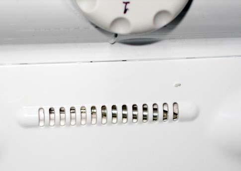
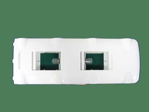
 and a fan located in the freezer compartment(behind the compartments partition - Fig. 2).")
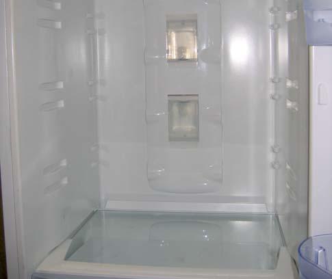
26 APPLIANCE THERMODYNAMICS: Interior chilling performance of new No-Frost appliance: The refrigeration system of the new no frost refrigerator consists of a cooling circuit whose main elements are a vertical finned evaporator (Fig 1) and a fan located in the freezer compartment(behind the compartments partition - Fig. 2).partments partition - Fig. 2). Fridge Air Delivery vent Position of defrost end sensor OPERATION Position of double fusible link Fridge Air Return Vent Drip tray Position of Freezer Air sensor (Fig 1) (Fig 2) The cold air that flows through the evaporator coil is routed to the Refrigerator compartment (Fig 3) and the freezer compartment (Fig 2) thereby causing the required cooling effect. Electronic Damper (cold air inlet to fridge) Fridge Air Return vent Position of Fridge Air Sensor (Fig 3) 26
 and the freezer compartment (fig. 5). Blue = Delivery Red = Return (Fig 5) 27")
27 Blue = Delivery Red = Return Intake vent OPERATION (Fig 4) The cold air is delivered from the vents serving the refrigerator compartment (fig. 4) and the freezer compartment (fig. 5). Blue = Delivery Red = Return (Fig 5) 27

28 The thermodynamic cycle is closed thanks to the intake of refrigerator air (Fig 3) and freezer air (Fig 2), whereby the air heated after the thermal exchange is cooled and dehumidified by the coil. The ice that accumulates on the coil is periodically removed by means of a system of heating elements, and the resulting melt water is collected in the drip tray and routed through the drain tube to the compressor bowl from which it evaporates. OPERATION (Fig 2) Electronic Damper (cold air inlet to fridge) Fridge Air Return vent Position of Fridge Air Sensor (Fig 3) 28
 8 Fridge Evaporator (RED) 9 Solenoid valve 10 Accumulated Gas Canister 11 Molecular filter EVAPORATOR COMPONENTS Low Pressure RED Fridge - Freezer circuit YELLOW Freezer Circuit")

29 Functional description of the refrigerant circuit: 1 Compressor 2 Condenser 3 Heating Tube (LIGHT BLUE) 4 Return Tube (GREEN) 5 Fridge Capillary Tube (RED) 6 Freezer Capillary Tube (YELLOW) 7 Freezer Evaporator (RED) 8 Fridge Evaporator (RED) 9 Solenoid valve 10 Accumulated Gas Canister 11 Molecular filter EVAPORATOR COMPONENTS Low Pressure RED Fridge - Freezer circuit YELLOW Freezer Circuit GREEN Return Tube COMMON COMPONENTS High Pressure LIGHT BLUE Heating Tube OPERATION Cold is generated inside the appliance by means of constant variations of pressure and volume of a constant mass of refrigerant fluid. The refrigerant is compressed in the compressor, and due to the effect of the work expended by the compressor motor, it is brought to the state of superheated vapour. Before entering the condenser, the refrigerant passes through a hot anti-condensation tube. In the condenser the refrigerant releases heat to the exterior environment and then, by flowing through the capillary tube, the refrigerant is subjected to a sudden pressure drip that enables it to evaporate at low temperature. The fluid evaporates inside the refrigerator and freezer evaporators. During these phase changes the fluid absorbs heat from the surrounding environment thereby causing the refrigerator and freezer compartments to be chilled down to the required temperature values, which are regulated by means of suitable thermostat control. Function of the solenoid valve: The solenoid valve is controlled in such a way as to route the cold refrigerant to the refrigerator or freezer compartment depending on the user settings of the temperature adjustment knobs, thereby allowing full independence of cooling demands from the two compartments. When the cooling demand is transmitted from the freezer compartment the thermodynamic circuit is closed by the solenoid valve thereby intensifying cooling capacity in the freezer compartment. When the cooling demand comes from the refrigerator compartment the thermodynamic circuit causes the fluid to evaporate first in the refrigerator evaporator and then to cool also the freezer compartment. 29


30 3. COMPONENTS: ELECTRONIC THERMOSTAT NO FROST FRIDGE-FREEZER. Control Panel Multiflow unit COMPONENTS Mechanical damper sensor Thermostat PCB Mechanical damper Fridge compartment 30


31 Light Fixture COMPONENTS Freezer compartment Freezer compartment air sensor Rear Components: Key: 1. Compressor Compartment 2. Compressor 3. Water Bowl 4. Filter 5. Delivery Tube 6. Return Tube 7. Capillary tube 31


32 BASIC ELECTRONIC STATIC FRIDGE-FREEZER OR EVOLUTION MODEL Basic control panel Evolution control panel COMPONENTS Freezer Air Sensor Freezer Evaporator Fridge compartment Freezer compartment 32


33 Fridge fan (evolution model only) and lamp holder Ice container and drawer Evolution COMPONENTS Base Main PCB (strip) Display/Interface PCB: 1 2 Main PCB Cover: 1. Main PCB Cover 2. Hardware Key Interface 33

34 COMPONENTS 7 Rear Components: Key: 1. Compressor Compartment 2. Compressor 3. Water Bowl 4. Filter 5. Main PCB 6. Delivery Tube 7. Return Tube 8. Capillary tube 34


35 ELECTRONIC THERMOSTAT DOUBLE DOOR NO FROST. Control Panel Freezer Air Sensor COMPONENTS Thermostat PCB Freezer compartment fan Freezer compartment Freezer compartment evaporator coil 35
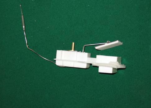
36 Fridge compartment Damper Cover COMPONENTS Multiflow unit Light Fixture Mechanical damper Mechanical damper sensor 36

37 COMPONENTS Rear Components: Key: 1. Compressor Compartment 2. Compressor 3. Water Bowl 4. Filter 5. Delivery Tube 6. Return Tube 7. Capillary tube 37
38 SPECIFICATIONS OF LOADS REFRIGERANT CIRCUIT SOLENOID VALVES Dual state: Load type: inductive Electrical specifications (datasheet): Voltage (V): Frequency (Hz): Resistance min/max(w): 1600/3750 ± 10% at T=25 C Control techniques: Control is executed by transmitting a finite number of positive or negative half-waves of the voltage FRIDGE AC FAN UNITS Electrical characteristics (measured) Voltage (V): Frequency (Hz): Resistance (W): - - Min/max Power (W): 3.5 Control techniques: Control is executed by transmitting the entire mains voltage FREEZER AC FAN UNITS Electrical characteristics (measured) Voltage (V): Frequency (Hz): 50 Resistance (W): 529 +/- 10% Min/max Power (W): 3.1/16 Control techniques: Control is executed by transmitting the entire mains voltage HEATING ELEMENTS Load type: resistive Electrical specifications (datasheet): Voltage (V): 220V/240 Frequency (Hz): 50 drip tray: Power (W): 30 ± 10 Resistance (W): 1613 ± 5% evaporator coil Power (W): 125 ± Resistance (W): 387 ± 10% Control techniques: Control is executed by transmitting the entire mains voltage ELECTRONIC DAMPER Stepping: Load type: 2-phase stepper motor Electrical specifications (datasheet): Voltage (V): 12V DC Frequency (Hz): 50/60Hz Current (ma): 60 Control techniques: Dual pole control LAMPS Load type: resistive Electrical specifications (datasheet): Voltage (V): , Frequency (Hz): 50-60, 60 Power (W): 10 Power (W): 15 Power (W): 25 Control techniques: Control is executed by transmitting the entire mains voltage COMPRESSORS Load type: inductive Electrical specifications (datasheet): Voltage (V): Frequency (Hz): Control techniques: Control is executed by transmitting the entire mains voltage COMPONENTS 38
39 4. WIRING DIAGRAMS: WIRING DIAGRAMS 39
40 WIRING DIAGRAMS 40
41 WIRING DIAGRAMS 41
42 SENSOR DIAGRAM 1 WIRING DIAGRAMS Used in: Fridge-Freezer Appliance H =1750 Fridge-Freezer Appliance H =1850 Fridge-Freezer Appliance H =
43 SENSOR DIAGRAM 2 WIRING DIAGRAMS Used in: NF Fridge-Freezer Appliance H =1875 NF Fridge-Freezer Appliance H =
44 SENSOR DIAGRAM 3 WIRING DIAGRAMS Used in: Double Door Appliance H =1750 Double Door Appliance H =
45 SENSOR DIAGRAM 4 WIRING DIAGRAMS Used in: All products with mini PCB in control Panel 45
46 SENSOR DIAGRAM 5 WIRING DIAGRAMS Used in: Fridge-freezer appliances with special compartment 46
47 FREEZER COMPARTMENT FRONT SIDE ELECTRICAL WIRING DIAGRAM WIRING DIAGRAMS Used in all No Frost appliances: R1 = Coil heating element R2 = Drip tray heating element TF1 and TF2 = Fusible links MVZF = Freezer fan motor 47

48 5. ASSISTANCE: 5.1. DEMO MODE: The refrigerators shown in this manual are not equipped with the Demo Mode procedure AUTO TEST: The appliances feature an Autotest procedure that is able to assess correct operation of various loads and sensors. Electronic Thermostat Autotest: Activation of the Autotest procedure for this appliance must be performed by executing the following movements of the knob: 1. Turn the knob from its current setting to the minimum setting (appliance OFF position) ASSISTANCE 2. Turn the knob from OFF to the maximum setting. 3. Turn the knob from maximum to minimum (appliance OFF). 48

49 The function terminates automatically after 255 seconds. You can interrupt the autotest function by switching on the appliance by means of the freezer knob or by disconnecting and reconnecting the mains power supply. With regard to appliance loads driven by the PCB during the autotest procedure and the tested sensors, any faults will be signalled by flashing of the fridge lamp. Autotest for: Basis Electronic Fridge Freezers. Electronic Digit Fridge Freezers, Basic No Frost Electronic Fridge Freezers. Activation of the Autotest function for these appliances must be performed by executing the following procedure: 1. Turn the Fridge knob to the minimum position (compartment OFF). 2. Turn the Freezer knob to the minimum position (appliance OFF). ASSISTANCE 3. Press the SUPER FREEZER button for approximately 5 seconds. When the autotest procedure has been activated the 3 LEDs will illuminate steadily for approximately 5 seconds (if the digital interface is present the 2 digits will illuminate together with the LEDs). The function terminates automatically after 255 seconds. You can interrupt the autotest function by switching on the appliance by means of the freezer knob or by disconnecting and reconnecting the mains power supply. With regard to appliance loads driven by the PCB during the autotest procedure and the tested sensors, any faults will be signalled by flashing of the fridge lamp. 49
50 5.2. FAULTS AND SOLUTIONS: Fig Fig.2 Key: 1 = LED 1; 2 = LED 2; 3 = LED 3; 4 = DIGIT FR; 4 = DIGIT FZ The fault type can be signalled in various different ways: 1. by means of the LEDs in the case of the basic interface (see fig.1) 2. by means of the LEDs and digits in the case of the Evolution interface (see fig.2) Reading of faults shown by LEDs The control panel LEDs illuminate to show the fault in accordance with the following table (the LEDs remain lit as long as the fault persists). Fault Indication Led1 Led2 Led3 F01 Off Flashing Off F02 On Flashing Off F03 Off Flashing On F04 On Flashing On F05 Flashing Flashing On F06 On Flashing Flashing F07 Off Flashing Flashing F08 Flashing Flashing Off F09 Flashing Flashing Flashing F12 Off Off On F14 On Off On F21 On On Flashing F22 Flashing On On F23 Flashing On Flashing F24 Off On Flashing F25 On Off Flashing LED Fault Table Critical Faults Non-critical Faults The first 9 faults are critical: the user will have to call service to repair the appliance; the next 8 faults can be checked by a technical engineer by means of the autotest procedure. ASSISTANCE 50
51 5.2. DIGITAL FAULTS AND SOLUTIONS: FAULT CAUSE CORRECTIVE ACTIONS F01 Compressor relay sticking - Check for water leaks that may affect connector J1 causing the relative contacts to short; - Check the motor terminal PCB (any problems due to incorrect connection may cause short-circuits); - Renew motor; - Renew PCB. - Check efficiency of contacts on PCB connector J1; - Check that there is an impedance value on wiring connector J1 between pins 3 and 2 that is compatible with the value given in the specific table. - Check that the compressor is not stopped due to overtemperature conditions (thermal cutout open) - Renew motor; - Renew PCB. - Renew PCB. - Check efficiency of contacts on PCB connector J6; - Check impedance on wiring connector J6 pins 2 and 1, ensuring that the value is compatible with the value given in the relevant table; - Check correct connection of the freezer fan on the freezer compartment wiring junction box; - Renew freezer fan unit; - Renew PCB. F02 F03 Compressor relay open Faulty power PCB F04 Freezer fan unit does not run F05 F06 Electronic damper does not open/close Short circuit of triac controlling defrost heating element - Check efficiency of contacts on PCB connector J3; - Check efficiency of the electronic damper connection to the foam embedded connector behind the multiflow unit; - Renew electronic damper; - Renew PCB. - Check efficiency of contacts on PCB connector J6; - Check condition by checking for impedance on wiring connector J6 pins 3 and 4 - Check connections of the defrost heating elements and possible short circuits on the freezer compartment wiring junction box; - Renew heating element. - Renew PCB. - Check efficiency of contacts on PCB connector J6; - Check for continuity of the defrost heating element on pins 3 and 4 of connector JK6, ensuring that the impedance value read is compatible with the value given in the relevant table; - Check for the correct connection of the defrost heating element and the drip tray heating element on the freezer compartment wiring junction box; - Check the correct impedance value on the defrost heating element across the heating element terminals; - Check that the fusible links are not open; - Renew defrost heating element; - Renew PCB. ASSISTANCE F07 No power draw of defrosting heating element 51
52 FAULT CAUSE CORRECTIVE ACTIONS F08 Incorrect switching of solenoid valve - Check efficiency of contacts on PCB connector J8; - Check for impedance on wiring connector J8 pins 2 and 1 and ensure that the value is compatible with the value given in the relevant table; - Check correct switching of the solenoid valve. Check, with the compressor running, that the solenoid valve switches when the refrigerator compartment is set to OFF by means of the temperature control knob - Renew solenoid valve; - Renew PCB. F09 F12 F14 F21 F22 F23 File setup error (EEPROM not programmed or faulty). No communication between display PCB and control PCB FRIDGE Evaporator NTC sensor open / short circuit Faulty power PCB FRIDGE Air NTC sensor open / short circuit FREEZER Air NTC sensor open / short circuit - In the case of an original production PCB, renew PCB and EEPROM; - In the case of replacement PCB and EEPROM, check correct insertion of EEPROM in PCB socket. For LED interface PCB: - Check efficiency of contacts on PCB connector J13; - Check continuity of connector J13 / 5-way and 7-way connectors of LED PCB; - Renew main PCB; - Renew display PCB; For Digit interface PCB: - Check efficiency of contacts on PCB connector J13; - Check continuity of connector J13 / 4-way interface PCB connector; - Renew main PCB; - Renew display PCB. - Renew PCB. - Renew PCB. - Check efficiency of contacts of PCB connector J11; - Check NTC sensor, ensuring that the impedance value read on pins 3 and 4 of wiring connector J11 is compatible with the values in the temperatureimpedance correlation table (also heat the sensor by holding it with your hand where possible and checking the change in the impedance value); - Renew PCB. - Check efficiency of contacts of PCB connector J11; - Check NTC sensor, ensuring that the impedance value read on pins 1 and 2 of wiring connector J11 is compatible with the values in the temperatureimpedance correlation table (also heat the sensor by holding it with your hand where possible and checking the change in the impedance value) - Renew PCB. - Renew appliance - Check efficiency of contacts of PCB connector J11; - Check NTC sensor, ensuring that the impedance value read on pins 5 and 6 of wiring connector J11 is compatible with the values in the temperatureimpedance correlation table (also heat the sensor by holding it with your hand where possible and checking the change in the impedance value); - Renew PCB. - Check efficiency of contacts of PCB connector J11; - Check NTC sensor, ensuring that the impedance value read on pins 1 and 2 of wiring connector J11 is compatible with the values in the temperatureimpedance correlation table (also heat the sensor by holding it with your hand where possible and checking the change in the impedance value) - Renew PCB. ASSISTANCE F24 Ambient NTC sensor UI F25 FREEZER Evaporator NTC sensor open / short circuit 52
53 5.5. TROUBLESHOOTING: PROBLEM Fails to switch on. Compressor fails to start Compressor runs but appliance fails to cool. Compressor unable to start. Water under crisper drawers. Water on floor. ANALYSIS - Check voltage on socket outlet. - Check power cord. - Check continuity of windings - Check operation of Klixon relay. - Faulty PCB. - Appliance set to OFF. - Compressor is cold - check refrigerant charge. - Compressor is very hot - Check for traces of oil or refrigerant circuit is blocked. - Check for possible faulty compressor. - Faulty Klixon relay. - Faulty compressor. - Mains voltage very low. - Drain hole blocked. - Container or wrapping paper touching refrigeration wall. - Condensate collection bowl broken. - Water drain tube incorrectly positioned. - Condensate collection bowl not in contact with compressor. Compressor fails to stop. Compressor fails to start. Door open alarm sounds continuously. - Faulty thermostat. - Incorrectly positioned thermostat. - Unsuitable installation on electrical Klixon. - Door fails to close properly. - Refrigerant circuit insufficient charge or blocked. - Damaged compressor. - Check Thermostat/PCB. - No magnet in door. - Faulty PCB. - Door is distorted. ASSISTANCE Display switches off intermittently. For No-Frost appliances: the compartments are insufficiently cold. For No-Frost appliances: the refrigerator compartment does not cool properly. Refrigerator compartment too cold - food tends to freeze. - Check display cable. - Check display PCB. - Evaporator coil clogged with ice. - Check fusible link. - Check heating elements. - Chilled air suction fan motor. - Ice has formed in the duct between the refrigerator and freezer compartments. - Check temperature sensors. 53


 responsible for securing the")


54 5.6. DISASSEMBLY: NO FROST ELECTRONIC THERMOSTAT. Removing the Display PCB: 1. Remove plastic cover from both sides of the refrigerator. 3. Pull the control panel (pressure fit) and remove the temperature control knob. 2. Unscrew the two screws (one for each side) responsible for securing the control panel. 4. Disconnect the PCB terminals. ASSISTANCE Removing fridge-freezer refrigerator compartment components: 1. Remove fridge compartment shelves. 2 Remove damper temperature adjustment knob. 54


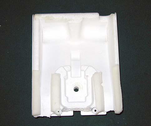
55 3 Remove plastic cover from light fixture. 5 Pull multiflow unit causing it to slide downwards by a couple of centimetres. 4 Unscrew the screws at base of multiflow unit and screw inside lamp holder. 6 Disconnect terminals from lamp holder. 7 Extract pressure-fit damper and remove with your hands. ASSISTANCE 55


56 Removing Fridge-Freezer freezer compartment components: 1 Remove the drawer from the freezer compartment. 3 Insert a slotted screwdriver into the cover upper holes to unclip the cover. 4 Pull cover forward. 2 Unscrew the five cover screws. 5 Detach the two clips (one on each side). Pull outwards. ASSISTANCE 56


57 6 Disconnect fan terminals. Removing double door appliance freezer compartment components: 1. Remove small plastic cover. 3 Pull cover. 4 Unscrew the two screws holding the internal part of the cover at the point in which the fan is mounted. 2. Insert a slotted screwdriver in both sides of the cover and detach. ASSISTANCE 5 Pull cover outwards. 57


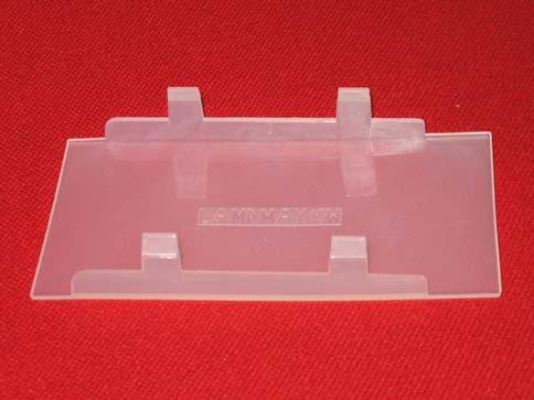
58 6 Detach fan connector. To remove or refit, simply apply pressure in the necessary direction. To remove the cover of the freezer compartment air return vent simply insert a slotted screwdriver in the outer part and press upwards, taking care you do not break off the fixing clips. N.B.: The freezer compartment air temperature sensor is attached to a specific location. To remove the cover of the freezer compartment air return vent simply insert a slotted screwdriver in the outer part and press upwards, taking care you do not break off the fixing clips. Disassembling double door appliance fridge compartment: 1. Detach the two lamp covers. ASSISTANCE 3. Una volta svitato tirarlo. 2 Unscrew the two screws that secure the multiflow unit to the interior wall of the refrigerator compartment 58


59 3 Pull the multiflow unit causing it to slide downwards, taking care not to damage the damper sensor. 5 Remove the damper temperature adjustment knob. 6 Unscrew the two screws that secure the plastic cover and withdraw the cover by pushing it downwards. 4 Disconnect the lamps power terminal. 7 The damper features a pressure-fit systems. To remove it no tools are required. ASSISTANCE 59


60 Removing the water collection bowl: 1. Use a screwdriver to detach the clips on both sides. 2. After detaching the clips remove the compressor compartment. ASSISTANCE 60


")
61 BASIC ELECTRONIC STATIC FRIDGE-FREEZER OR EVOLUTION MODEL Removing the Display PCB: 1. Remove plastic cover from both sides of the refrigerator. 3. Disconnect the PCB terminals. 2 Unscrew the two screws (one on each side) responsible for securing the control panel. 4. Press the fixing tabs and remove the PCB Removing the fan: 1. Remove the refrigerator fan cover by pressing with your hand on one of the two sides and then extract it. 2. Unscrew the two screws (one on each side) responsible for fixing the fan. ASSISTANCE 3. Detach the connector. 61


62 Removing the Lamp holder: 1. Slide the plastic cover to the rear. 3. Unscrew the screws on both sides of lamp holder. 2. Remove cover. 4. Disconnect the terminal board. Removing the Main PCB: 1. Undo the plastic clips securing the plastic cover. 2. Remove the cover. ASSISTANCE 3. Disconnect the PCB terminals. 62

63 4. Remove PCB from cover. Removing the water collection bowl: 1. Use a screwdriver to detach the clips on both sides. 2. After detaching the clips remove the compressor compartment. ASSISTANCE 63
Essentia Project Artica Platform No Frost 60 cm Appliances 2011
 Essentia Project Artica Platform No Frost 60 cm Appliances 2011 Event Ca Maiano, May 2011 Presenter Piotr Kelm Francesco Nieli 0 Legend and User Interface Legend THR3 Interface (SQG_CL_32) MID Indesit
Service Quick Guide SQG_CL_15/01_EN
 Service Quick Guide SQG_CL_15/01_EN Indesit Company, Service Department Table - New Platform 2005 Electronic Refrigerators, combination and double-door 1 LED1 LED2 LED3 2 Table 1 In the case of the Led
SERVICE MANUAL REFRIGERATION
 SERVICE MANUAL REFRIGERATION Electrolux Home Products S.p.A. Spares Operations Italy Corso lino Zanussi, 30 I - 33080 Porcia (PN) Fax +39 0434 394096 S.O.I. Edition: 10.2006 Publication no. 599 38 38-50
SERVICE MANUAL REFRIGERATION
 SERVICE MANUAL REFRIGERATION ELECTROLUX HOME PRODUCTS S.p.A. Publication no. Spares Operations Italy 599 37 75-07 Corso Lino Zanussi, 30 060824 I - 33080 PORCIA / PN (ITALY) ITZ/SERVICE/AA Fax +39 0434
SERVICE MANUAL REFRIGERATION
 SERVICE MANUAL REFRIGERATION ELECTROLUX ZANUSSI S.p.A. Publication No. Spares Operations Italy 599 35 40-29 Corso Lino Zanussi, 30 020806 I - 33080 PORCIA / PN (ITALY) ITZ/SERVICE/AA EUROFLEC With exposed
EGE Manisa 70 cm BIR Carinaro 55 cm. Fabriano June Presenter Francesco Nieli
 EGE Manisa 70 cm BIR Carinaro 55 cm Fabriano June 2012 Presenter Francesco Nieli Keys and Interfaces Manisa EGE key Carnaro BIR key Tiny Full interface (SQG_CL_??) Tiny SD interface (SQG_CL_??) New LED
Service Information. WNes 2956 appliance documentation. Service Information no. 27/2004 LHG/TKD-Fe/June SI
 After Sales Service International Service Information Service Information no. 27/2004 LHG/TKD-Fe/June 2004 WNes 2956 appliance documentation Page 1/26 Contents 2.0. Extract from Operating Instructions
Side-by-side combined refrigerator-freezer
 REPAIR INSTTRUCTTI I IONS Side-by-side combined refrigerator-freezer 1 SAFETY... 2 4.1 Electronic controller... 8 1.1 Safety instructions... 2 1.2 Repair instructions... 2 2 INSTALLATION... 3 3 OPERATION...
Refrigerator KE T
 Refrigerator KE 680-1-3T Service Manual: H8-74-07 Responsible: U. Laarmann KÜPPERSBUSCH HAUSGERÄTE AG E-mail: uwe.laarmann@kueppersbusch.de Tel.: (0209) 401-732 Customer Service Fax: (0209) 401-743 Postfach
KitchenAid Food Stream Solutions Classic and Integrated Series
 KitchenAid Food Stream Solutions Classic and Integrated Series KitchenAid Chapter list Installation Range overview Installation General Information Function Compressor Power Control Board Defrosting Heating
4. ALIGNMENT AND ADJUSTMENTS
 4-1) Forced Operation Function (Pull-down / Refrigerator Defrost / Refrigerator. Freezer-Defrost / Cancellation) 28 4-2) Sound function 29 4-3) Exhibition Function 29 4-4) Self-Diagnostics Function29 4-5)
Service Information. HOTPOINT SIDE-BY-SIDE FRIDGE FREEZERS (7 ~ Segment Version) Indesit Company UK Ltd
 Indesit Company UK Ltd") 5407399 Issue 2 March 2011 HOTPOINT SIDE-BY-SIDE FRIDGE FREEZERS (7 ~ Segment Version) Models Covered Comm. Code Energy Band 'A' Models MSZ801DF 48862 MSZ802DF 46196 MSZ803DF 48863 MSZ806DF 57217 Service
5407399 Issue 2 March 2011 HOTPOINT SIDE-BY-SIDE FRIDGE FREEZERS (7 ~ Segment Version) Models Covered Comm. Code Energy Band 'A' Models MSZ801DF 48862 MSZ802DF 46196 MSZ803DF 48863 MSZ806DF 57217 Service
OWNER S MANUAL. High-Wall Fan Coil Unit CONTENTS
 OWNER S MANUAL High-Wall Fan Coil Unit Page GENERAL 2,3 OPERATING MODES 2 REMOTE CONTROL 2 OPERATION 3-9 REMOTE CONTROL OPERATION 3 INDOOR UNIT DISPLAY 5 EMERGENCY OPERATION 5 PRESSING THE ON/OFF BUTTON
Owner s Manual TABLE OF CONTENTS
 40MBDQ Ducted Style Ductless System Sizes 18 to 48 Owner s Manual TABLE OF CONTENTS PAGE A NOTE ABOUT SAFETY... 2 GENERAL... 2 PARTS LIST... 3 DISPLAY PANELS... 4 FUNCTION BUTTONS... 5 REMOTE CONTROL...
Owner's Manual TABLE OF CONTENTS
 40MAQ High Wall Ductless System Sizes 09 to 36 Owner's Manual TABLE OF CONTENTS PAGE A NOTE ABOUT SAFETY... 2 GENERAL... 2 PART NAMES... 3 FUNCTION BUTTONS... 4 DISPLAY PANELS... 5 REMOTE CONTROL... 6
Refrigerated air dryers
 Refrigerated air dryers OPERATING AND MAINTENANCE MANUAL Original instructions 38178800319 OPERATING AND MAINTENANCE MANUAL - Contents 1 CONTENTS CONTENTS... 1 Chapter 1 IDRY ELECTRONIC CONTROLLER...
Dough Retarder Prover. Service Manual
 Service Manual Revision 3 June 2000 Dough Retarder Prover - Service Manual RBC MKII Controller Revision 6 Page 2 CONTENTS Page(s) 1. INTRODUCTION 3 2. RBC MK 2 CONTROLLER OPERATION 5-9 Process Cycle Overview
TABLE OF CONTENTS REFRIGERATOR-FREEZER. Model No. NR-BN34FX1 Model No. NR-BN34FW1
 Order Number GORR1405001CE REFRIGERATOR-FREEZER Model No. NR-BN34FX1 Model No. NR-BN34FW1 Product-Color X:Stainless W:White Destination E(Europe Continental) B(U.K.) TABLE OF CONTENTS PAGE 1 Safety Precautions-----------------------------------------------
OPERATION MANUAL. Indoor unit for air to water heat pump and sanitary warm water tank for air to water heat pump system EKHBH007A EKHBX007A
 OPERATION MANUAL Indoor unit for air to water heat pump and sanitary warm water tank for air to water heat pump system EKHBH007A EKHBX007A EKHBH007A*** EKHBX007A*** Indoor unit for air to water heat pump
Service Information. HOTPOINT Freestanding Frost Free Fridge Freezers
 5407423 Issue 1 Feb. 2009 HOTPOINT Freestanding Frost Free Fridge Freezers (Version 2) Refer to Insert below Models Comm. Covered Code FF187EA 40729 FF187EG 39780 FF187EK 53950 FF187EP 39775 FF187EPL 53947
PC870 American Style Fridge Freezer
 PC870 American Style Fridge Freezer Installation, Use and Maintenance Customer Care Department The Group Ltd. Harby Road Langar Nottinghamshire NG13 9HY T : 01949 862 012 F : 01949 862 003 E : customer.care@cda.eu
OWNER S MANUAL. R 410A Ductless Split System Air Conditioner and Heat Pump
 R 410A Ductless Split System Air Conditioner and Heat Pump Models DLC4(A/H) Outdoor Unit, DLF4(A/H) Indoor Unit Sizes 9K, 12K, 18K, 24K, 30K and 36K Please read the operating instructions and safety precautions
OPERATING MANUAL. AIR CONDITIONER Duct Type. Indoor Unit ARTG36LH ARTG45LH ARTG54LH ARTG60LH PART NO KEEP THIS MANUAL FOR FUTURE REFERENCE
 OPERATING MANUAL AIR CONDITIONER Duct Type Indoor Unit ARTG36LH ARTG45LH ARTG54LH ARTG60LH KEEP THIS MANUAL FOR FUTURE REFERENCE PART NO. 9374379583 CONTENTS SAFETY PRECAUTIONS... 2 FEATURES AND FUNCTIONS...
HOW TO USE THE FREEZER COMPARTMENT PAGE 16
 33051-gb.fm5 Page 12 Tuesday, December 22, 1998 3:52 PM GB CONTENTS BEFORE USING THE APPLIANCE PAGE 13 SAFEGUARDING THE ENVIRONMENT PAGE 13 PRECAUTIONS AND GENERAL RECOMMENDATIONS PAGE 14 HOW TO USE THE
HOW TO OPERATE THE FREEZER COMPARTMENT PAGE 17 HOW TO DEFROST THE FREEZER COMPARTMENT PAGE 19
 33056-GB.fm5 Page 13 Saturday, January 16, 1999 8:47 AM TABLE OF CONTENTS GB BEFORE USING THE APPLIANCE PAGE 14 SAFEGUARDING THE ENVIRONMENT PAGE 14 PRECAUTIONS AND GENERAL HINTS PAGE 15 HOW TO OPERATE
OPERATION MANUAL. Indoor unit for hot water heat pump system and options EKHBH016AB EKHBX016AB
 OPERATION MANUAL Indoor unit for hot water heat pump system and options EKHBH016AB EKHBX016AB EKHBH016AB*** EKHBX016AB*** Indoor unit for hot water heat pump system and options CONTENTS Page Introduction...1
R410A. AIR CONDITIONER DUCT TYPE / ART Series OPERATING MANUAL. REFRIGERANT This Air Conditioner contains and operates with refrigerant R410A.
 AIR CONDITIONER DUCT TYPE / ART Series OPERATING MANUAL KEEP THIS OPERATION MANUAL FOR FUTURE REFERENCE R410A REFRIGERANT This Air Conditioner contains and operates with refrigerant R410A. THIS PRODUCT
BFFF HUY. Partial Frost-free Bottom Combi Nyíregyháza Factory
 BFFF HUY Partial Frost-free Bottom Combi Nyíregyháza Factory Nyíregyháza Factory Electrolux Code HUY Nyíregyháza HUY Satu Mare ROA Jászberény HUC Product Range HUY HUY production: bottom combis Convenience
MR4PMUHV Electronic. Temperature/Defrost Control with Relay Pack
 Master Catalog 125 Temperature Controls Section A Product/Technical Bulletin Issue Date 1098 MR4PMUHV Electronic Temperature/Defrost Control with Relay Pack The MR series temperature controls are designed
HTD. High Temperature Non-Cycling Refrigerated Compressed Air Dryers. Operation & Maintenance Manual. MODELS HTD 21 thru HTD 100
 HTD High Temperature Non-Cycling Refrigerated Compressed Air Dryers Operation & Maintenance Manual MODELS HTD 21 thru HTD 100 - TABLE OF CONTENTS - 1.0 GENERAL 2 1.1 How to use this manual 1.2 Symbols
OPERATING MANUAL AIR CONDITIONER DUCT TYPE. ART Series KEEP THIS MANUAL FOR FUTURE REFERENCE FUJITSU GENERAL LIMITED P/N
 OPERATING MANUAL AIR CONDITIONER DUCT TYPE ART Series KEEP THIS MANUAL FOR FUTURE REFERENCE FUJITSU GENERAL LIMITED P/N9374379293-02 CONTENTS SAFETY PRECAUTIONS... 1 NAME OF PARTS... 2 PREPARATORY OPERATION...
3. OPERATING INSTRUCTIONS & INSTALLATION
 3-1) Digital Panel 20 3-2) Temperature Control Function 20 3-3) Power Freeze and Power Cool Functions 21 3-4) Child Lock Function 21 3-5) Ice & Water Dispenser Function 22 3-6) C-Fan Motor Delay Function
PC71 American Style Fridge Freezer
 PC71 American Style Fridge Freezer Installation, Use and Maintenance Customer Care Department The Group Ltd. Harby Road Langar Nottinghamshire NG13 9HY T : 01949 862 012 F : 01949 862 003 E : customer.care@cda.eu
Portable Air Conditioner, Dehumidifier,Heater and Fan utilizing Heat Pump Technology
 Portable Air Conditioner, Dehumidifier,Heater and Fan utilizing Heat Pump Technology OWNER'S MANUAL Model # KY-34 3046364 Please read owner s manual carefully before operating unit. TABLE OF CONTENTS INTRODUCTION...3
USING THE REFRIGERATOR COMPARTMENT
 USING THE REFRIGERATOR COMPARTMENT Switching the appliance on Starting the appliance Insert the plug. The light, located under the control panel or inside the product (depending on model) comes on when
CA5000 Liquid CO 2 Freezer Backup System
 CA5000 Liquid CO 2 Freezer Backup System OPERATING INSTRUCTIONS MANUAL HAMPSHIRE CONTROLS CORPORATION ONE GROVE STREET / P.O. BOX 516, DOVER, NEW HAMPSHIRE USA 03821 TEL. (603) 749-9424 FAX (603) 749-9433
User manual CLIMATIC 200/400 - Controller. Providing indoor climate comfort
 User manual CLIMATIC 2/4 - Controller Providing indoor climate comfort MUL35E-56 9-26 INDEX CONTENTS PAGE INDEX 1 GENERAL DESCRIPTION 2 THE KEYPAD, Climatic 2 3 THE KEYPAD, Climatic 4 4 THE KEYPAD REMOTE
OPERATING MANUAL Enertronic Control System 2
 OPERATING MANUAL Enertronic Control System 2 The integrated control system for Lennox chillers in the Ecologic range Manufacturer: Lennox Benelux B.V. Postbus 1028, 3860 BA NIJKERK Watergoorweg 87, 3861
Service Documentation
 After Sales Service International Service Manual No. 16/2010 Service Documentation LWL/KDT-baj/30.06.10 Appliance Documentation GKv 4310 / 4360 from Index 20 Commercial refrigerator, ventilated GKv 5730
User instructions DHP-AT
 User instructions DHP-AT VUGFC202 If these instructions are not followed during installation and service, Danfoss A/S liability according to the applicable warranty is not binding. Danfoss A/S retains
Owner s Manual TABLE OF CONTENTS
 40MHH High Wall Ductless System Sizes 09 to 24 Owner s Manual TABLE OF CONTENTS PAGE A NOTE ABOUT SAFETY... 2 GENERAL... 2 PART NAMES... 3 INDOOR UNIT DISPLAY INDICATOR... 4 REMOTE CONTROL... 4 FUNCTION
OPERATION INSTRUCTIONS DEMAND DEFROST CONTROL BOARD MODEL FOR USE WITH MODELS: AFFINITY, ECHELON, ACCLIMATE HEAT PUMP SERIES
 OPERATION INSTRUCTIONS DEMAND DEFROST CONTROL BOARD MODEL 500644 FOR USE WITH MODELS: AFFINITY, ECHELON, ACCLIMATE HEAT PUMP SERIES A047-001 FIGURE 1: Demand Defrost Control Module ANTI-SHORT CYCLE DELAY
Owner's Manual TABLE OF CONTENTS
 40MB*D Ducted Style Ductless System Sizes 09 to 48 Owner's Manual TABLE OF CONTENTS PAGE A NOTE ABOUT SAFETY... 2 GENERAL... 2 PARTS LIST... 3 DISPLAY PANELS... 4 FUNCTION BUTTONS... 5 REMOTE CONTROL...
EDW500 / EDW503. Electronic Controls for Dishwashers
 EDW500 / EDW503 Electronic Controls for Dishwashers ESSE-N / A.S. October 2004 EDW500 - EDW503 EDW500 and EDW503: new entry level electronic controls for dishwashers in the DIVA family Intended to replace
PRODUCT DESCRIPTION CONTROLS
 PRODUCT DESCRIPTION A. Refrigerator Compartment 1. Crisper drawer 2. Shelves / Shelf area 3. Thermostat control knob/light 4. Door trays 5. Bottle rack 6. Removable bottle restraint 7. Rating plate (at
Indesit Company. Multiplo 2008 Jaeger Platform. Fabriano, May 2008
 Indesit Company Multiplo 2008 Jaeger Platform Fabriano, May 2008 1 Legend Multiplo F Flush Product name Multiplo SF Semi-flush 2 Interfaces REAR WELL FRONT WELL PROGRAMMED COOKING ZONE REAR COOKING ZONE
USER MANUAL. Portable Air Conditioner and Heater With Heat Pump Technology PAC18. Please read this manual carefully prior to operating the product.
 USER MANUAL Portable Air Conditioner and Heater With Heat Pump Technology PAC12 PAC15 PAC18 Please read this manual carefully prior to operating the product. TABLE OF CONTENTS INTRODUCTION... 3 IMPORTANT
ENGLISH REMOTE CONTROL MANUAL
 ENGLISH REMOTE CONTROL MANUAL CONTENT PRECAUTIONS...1-2 USING THE REMOTE CONTROL UNIT...3 OPERATION...4-9 Thank you for purchasing our Room Air Conditioner. Before using your air-conditioner, please read
Operation Guide 3408
 MO1212-EA 2013 CASIO COMPUTER CO., LTD. Operation Guide 3408 About This Manual Depending on the model of your watch, display text appears either as dark figures on a light background or light figures on
Service. Manual RADIANT HOBS PLATFORM ISSUE MAR. 2008
 1 ISSUE MAR. 2008 RADIANT HOBS PLATFORM 2008 Model. Comm. Covered Code KRO 632 TD X 52968 KRO 632 TD Z 52969 KRO 642 D B 52972 KRO 642 D X 52973 KRO 642 D Z 52974 KRO 642 TO B 52975 KRO 642 TO X 52976
B-764 FULL NF REFRIGERATOR CONTROL SPECIFICATIONS
 B-764 FULL NF REFRIGERATOR CONTROL SPECIFICATIONS 1 Page 1 of 30 HISTORY SHEET Date of Issue 29.11.2004 Prepared by Ferkan GULBAS Approved by Emre ARISOY Revisions. Rev. # Revised page(s) Revision and
Operating instructions Page 12
 Operating instructions Page 12 Refrigerator with explosion-proof interior container Read the operating instructions before switching on for the first time 7082 271-00 LKEXv 910 Disposal notes The appliance
CASSETTE TYPE. AUT Series FUJITSU GENERAL LIMITED AIR CONDITIONER OPERATING MANUAL P/N KEEP THIS MANUAL FOR FUTURE REFERENCE AM PM
 OPERATING MANUAL AIR CONDITIONER CASTE TYPE AUT Series AM PM 6 9 5 8 KEEP THIS MANUAL FOR FUTURE REFERENCE FUJITSU GENERAL LIMITED P/N9704 CONTENTS SAFETY PRECAUTIONS... NAME OF PARTS... PREPARATORY OPERATION...
Heat Pump Defrost Board Replacement Kit
 Bard Manufacturing Company, Inc. Bryan, Ohio 43506 8620-223 Heat Pump Defrost Board Replacement Kit KIT FEATURES This kit is made up of the current defrost control board 8201-129 and a new defrost sensor.
REMOTE CONTROL FAN SPEED ECONOMY BATTERY LOW. owner s manual
 REMOTE CONTROL AUTO FAN SPEED COOL PM ECONOMY BATTERY LOW owner s manual Hello and congratulations on purchasing a Breezair Ducted Cooler for your home. Breezair coolers have been designed to provide quiet,
OWNER'S MANUAL R-410A Duct Free Split System Air Conditioner and Heat Pump
 R-10A Duct Free Split System Air Conditioner and Heat Pump Product Family: DFF(A/H)H, DFC(A/H) Please read the operating instructions and safety precautions carefully and thoroughly before installing and
Updated: 17/03/2010 ELECTROLUX. CAREL ir33. Quick reference Handbook. Ver. 1.1 Eng. Pag.1/12
 CAREL ir33 Quick reference Handbook Pag.1/12 MAIN FEATURES OF THE INSTRUMENT USER INTERFACE 1. ON/OFF switch button UP button to increase temperature values 2. DOWN button to decrease values - Activates/deactivates
Operation Guide 5510
 MO1612-EA 2016 ASIO OMPUTER O., LTD. About This Manual Button operations are indicated using the letters shown in the illustration. Depending on the model of your watch, display text appears either as
Great Britain en. Installation, user and service manual. Control panel HMI Gas 310/610 ECO PRO
 Great Britain en Installation, user and service manual Control panel HMI Gas 310/610 ECO PRO Dear Customer, Thank you very much for buying this appliance. Please read through the manual carefully before
1. SAFETY WARNINGS INSTALLTION Location Reversing the Door Swing Levelling the Unit... 3
 Contents 1. SAFETY WARNINGS... 1 2. INSTALLTION... 2 2.1 Location... 2 2.2 Reversing the Door Swing... 2 2.3 Levelling the Unit... 3 2.4 Cleaning Before Use... 3 2.5 Before Using Your Unit... CE BC108
HEAT & COOL MODEL (REVERSE CYCLE)
") OPERATING MANUAL HEAT & COOL MODEL (REVERSE CYCLE) AIR CONDITIONER Duct Type Indoor Unit ARTG09LL ARTG12LL ARTG18LL KEEP THIS MANUAL FOR FUTURE REFERENCE P/N9374379439 CONTENTS SAFETY PRECAUTIONS... 1
OPERATING MANUAL HEAT & COOL MODEL (REVERSE CYCLE) AIR CONDITIONER Duct Type Indoor Unit ARTG09LL ARTG12LL ARTG18LL KEEP THIS MANUAL FOR FUTURE REFERENCE P/N9374379439 CONTENTS SAFETY PRECAUTIONS... 1
CAREL IR33+ CONTROLLER
 CAREL IR33+ CONTROLLER Programming Instructions The Carel IR33+ controller has a two-level menu system for programming the operation of the case; Level 1 and Level 2 program settings. Unlike IR33, the
UPS BATTERY TEST. Testing the UPS Battery (Verification Test) Locking models: 13/19/22-USGF, 13/19/22- USGR, 43/44-UDGR, 43/44-UDGF
 Locking models: 13/19/22-USGF, 13/19/22- USGR, 43/44-UDGR, 43/44-UDGF") 30 Armstrong Ave. Georgetown. Ont, L7G 4R9, Canada Tel: 800 800 5706 or 905 702 1441 Fax: 905 702 1442 www.minusforty.com SUBJECT: MODELS: UPS BATTERY TEST Testing the UPS Battery (Verification Test) Locking
30 Armstrong Ave. Georgetown. Ont, L7G 4R9, Canada Tel: 800 800 5706 or 905 702 1441 Fax: 905 702 1442 www.minusforty.com SUBJECT: MODELS: UPS BATTERY TEST Testing the UPS Battery (Verification Test) Locking
REMOTE CONTROL MANUAL
 REMOTE CONTROL MANUAL ENGLISH CONTENT PRECAUTIONS...1-2 USING THE REMOTE CONTROL UNIT...3 OPERATION... 4-9 Thank you for purchasing our Room Air Conditioner. Before using your air-conditioner, please read
Frost Checklist and Troubleshooting Guide for NDA1402 & NEA1402
 Frost Checklist and Troubleshooting Guide for NDA1402 & NEA1402 REFRIGERATOR BULLETIN R82-7A NOVEMBER 2007 USA SERVICE OFFICE Dometic Corporation 2320 Industrial Parkway Elkhart, IN 46516 574-294-2511
User manual. Fridge Freezer ZRT18100WA
 EN User manual Fridge Freezer ZRT18100WA Contents Safety instructions 2 Before first use 4 Daily use _ 4 Hints and tips _ 5 Safety instructions Before the installation and use of the appliance, carefully
Grant Aerona³. Air to Water High Efficiency Heat Pump Range. User Instructions
 Grant Aerona³ Air to Water High Efficiency Heat Pump Range User Instructions UK DOC 0112 Rev 1.0 April 2017 Special Tex t Formats The following special text formats are used in this manual for the purposes
PCR-300 PCR-300 RC. Installation and Operating Instructions
 PCR-300 PCR-300 RC Installation and Operating Instructions Electronic refrigeration control EB-PCR-04 EN1H-1924GE23 R1207 TABLE OF CONTENTS 11 Unpacking the unit and conditions of use 3 12 General instructions
SERVICE INSTRUCTION. DYNAMIC COOLING with 0 zone REFRIGERATION. Fridge/freezer with. Publication number
 SERVICE INSTRUCTION REFRIGERATION DISTRIPARTS AB BOX 501 S-562 80 NORRAHAMMAR Phone 036-31 80 00 Telefax 036-31 81 10 Telefax 036-31 80 88 Publication number 599 51 96-71 Rev. 04-04-20 SV/SERVICE DT/MA/AN
40KMC KMQ
 40KMC------301 40KMQ------301 OWNER S MANUAL Split system Global cassette indoor unit IR Remote Control Room Controller Zone Manager The unit can be used with infrared Remote Control, with the Carrier
LevControl LC PLUS OPERATING INSTRUCTIONS ALL OUR SYSTEMS COMPLY WITH DIRECTIVE 73/23 EEC - 89/336. Cod /0-12/97
 LevControl LC PLUS ALL OUR SYSTEMS COMPLY WITH DIRECTIVE 73/23 EEC - 89/336 OPERATING INSTRUCTIONS Cod. 71503277/0-12/97 WARNING!!! THE OPERATIONS LISTED BELOW AND THOSE MARKED BY THIS SYMBOL ARE STRICTLY
Lubrication cycle IP Enclosure Rating. 110 VAC, 220/230 VAC (50/60 Hz) Alarm Fault Relay Contacts. IP-55 (Liquid tight connector)
 Alarm Fault Relay Contacts. IP-55 (Liquid tight connector)") SMAC Controller Industrial Lubrication Systems Operation The SMAC Controller is a multi-purpose programmable controller used with industrial lubrication systems. Controller settings are saved whenever
SMAC Controller Industrial Lubrication Systems Operation The SMAC Controller is a multi-purpose programmable controller used with industrial lubrication systems. Controller settings are saved whenever
Fast Track Troubleshooting
 Fast Track Troubleshooting Models Covered: RF197ACPN French Door Refrigeration IMPORTANT SAFETY NOTICE For Technicians Only This service data sheet is intended for use by persons having electrical, electronic,
PDA20DX Air Purifying Dehumdifier Manual
 PDA20DX Air Purifying Dehumdifier Manual Index Important Safe Guards Ambient Environment For Operating Components Diagrams---Parts Names Operating Introduction---How to operate - Functions of Control Panel
OPERATION MANUAL. Daikin Altherma indoor unit EKHVMRD50ABV1 EKHVMRD80ABV1 EKHVMYD50ABV1 EKHVMYD80ABV1
 OPERATION MANUAL EKHVMRD50ABV1 EKHVMRD80ABV1 EKHVMYD50ABV1 EKHVMYD80ABV1 EKHVMRD50+80ABV1 EKHVMYD50+80ABV1 CONTENTS Page 1. Definitions... 1 2. Introduction... 2 2.1. General information... 2 2.2. Scope
PAT E N T System 88. COMPLIES WITH Singapore Standard : SS CP10 : 2005 British Standard : BS EN54-2 : 1998 BS EN54-4 : 1998 REV.00
 PAT E N T System 88 COMPLIES WITH Singapore Standard : SS CP10 : 2005 British Standard : BS EN54-2 : 1998 BS EN54-4 : 1998 REV.00 Pg 1 of 12 CONTENTS 1. GENERAL 1.1 Introduction 2 1.2 System Description
To suit Daikin FDY "F" Series. (and other models incorporating BRC1C61 Remote Controller)
") OPERATION MANUAL Split System Ducted Air Conditioner To suit Daikin FDY "F" Series hr C (and other models incorporating BRC1C61 Remote Controller) Dear Owner, Thank you for installing a DAIKIN Fully Ducted
OPERATION MANUAL Split System Ducted Air Conditioner To suit Daikin FDY "F" Series hr C (and other models incorporating BRC1C61 Remote Controller) Dear Owner, Thank you for installing a DAIKIN Fully Ducted
OPERATION MANUAL. Packaged air-cooled water chillers and packaged reversible air to water heatpumps EWAQ009ACV3 EWAQ010ACV3 EWAQ011ACV3
 OPERATION MANUAL Packaged air-cooled water chillers and packaged reversible air to EWAQ009ACV3 EWAQ010ACV3 EWAQ011ACV3 EWYQ009ACV3 EWYQ010ACV3 EWYQ011ACV3 EWAQ009ACW1 EWAQ011ACW1 EWAQ013ACW1 EWYQ009ACW1
USER'S MANUAL PU SENS 01 (A11) PU SENS 01 (A19) Sensor Control Panel
 PU SENS 01 (A19) Sensor Control Panel") USER'S MANUAL PU SENS 01 (A11) PU SENS 01 (A19) Sensor Control Panel PU SENS 01 CONTENTS Safety requirements... 3 Purpose... 4 Technical data... 4 Overall dimensions [mm]... 4 Mounting and set-up... 5
USER'S MANUAL PU SENS 01 (A11) PU SENS 01 (A19) Sensor Control Panel PU SENS 01 CONTENTS Safety requirements... 3 Purpose... 4 Technical data... 4 Overall dimensions [mm]... 4 Mounting and set-up... 5
4. Alignment and Adjustments
 . Alignment and Adjustments -) Forced Operation Function (Pull-down / Refrigerator Defrost / Refrigerator. Freezer-Defrost / Cancellation) 3 -) Self-Diagnostics Function 3-3) Load Operation Check Function
SAFETY INFORMATION INSTALLATION OPERATION CONSERVATION FREEZING DEFROSTING MAINTENANCE AND CLEANING
 MAINTENANCE EN CONTENTS EN SAFETY INFORMATION... 02--02 INSTALLATION... 03--03 OPERATION... 03--03 CONSERVATION... 04--04 FREEZING... 05--05 DEFROSTING... 05--05 MAINTENANCE AND CLEANING... 06--06 ENERGY
Operation Manual SCT14B and SCT18B. Inspection. 3 General Description. 3 General Requirements. 3 Standard Features.
 Spot Cooling Systems, Inc. 120 Century Drive Suite 00 Carrollton, TX 7006 00-6-776 Operation Manual SCT1B and SCT1B Warning! Improper installation, adjustment, alteration, service, or maintenance can cause
OPERATING MANUAL UTY-RNNYM P/N English
 OPERATING MANUAL English UTY-RNNYM P/N9373329206-04 OPERATING MANUAL CONTENTS SAFETY PRECAUTIONS... 1 NAME OF PARTS... 2 PREPARATORY OPERATION... 3 OPERATION... 4 TIMER FUNCTIONS... 6 ON/OFF TIMER... 6
Planet Super4F.S. User Instructions
 GB Planet Super4F.S. User Instructions USER INSTRUCTIONS VERY IMPORTANT! PLEASE MAKE SURE YOUR LOG BOOK ENCLOSED IS FILLED IN CORRECTLY. ALL CORGI REGISTERED INSTALLERS CARRY A CORGI ID CARD. BOTH SHOULD
REFRIGERATOR/FREEZER COMBINATION
 Operating Instructions REFRIGERATOR/FREEZER COMBINATION English BAAN 12 BAAN 12 s Contents Installation, 2 Positioning and connection Reversible doors Description of the appliance, 3 Overall view Accessories,
User Guide ems25plus. Page 1. Normal operation. Product interface
 Page 1 Product interface rmal operation During normal operation, EMS controllers display the information below. Assuming the product temperature is correct when the outlet is open, this means that the
HOW TO OPERATE THE FREEZER COMPARTMENT PAGE 15 HOW TO DEFROST THE FREEZER COMPARTMENT PAGE 17
 GB CONTENTS BEFORE USING THE REFRIGERATOR PAGE 13 SAFEGUARDING THE ENVIRONMENT PAGE 13 PRECAUTIONS AND GENERAL RECOMMENDATIONS PAGE 14 HOW TO OPERATE THE REFRIGERATOR COMPARTMENT PAGE 15 HOW TO OPERATE
Glass Door Merchandisers GDC10, GDC12F, GDC15, GDC23, GDC24F, GDC40, GDC40F, GDS47, GDC69
 Commercial Refrigerator And Freezer User s Manual Glass Door Merchandisers GDC10, GDC12F, GDC15, GDC23, GDC24F, GDC40, GDC40F, GDS47, GDC69 12/2015 Please read the manual thoroughly prior to equipment
Instruction Manual. Model S05 / CAPO
 Instruction Manual Model S05 / CAPO Table of contents 1 2 3 4 5 6 7 8 9 10 11 12 Introduction Intended use... 25 Follow the instructions - Symbols... 25 Your Map Coffee contact... 25 Safety warnings...
FX BLAST CHILLER ISO ISO 9001
 FX BLAST CHILLER ISO 14001 ISO 9001 Contents Environmental Management Policy 1 Disposal Requirements 1 Cabinet description 2 Controller Description Controller Operation 2 to 3 Alarms & Warnings 4 Parameter
OWNER S MANUAL. Evaporative Cooler. (English) (EA, EXH, EZH) ILL239-D ILL1140-A FAN SPEED REMOTE CONTROL ECONOMY
 (EA, EXH, EZH) ILL239-D ILL1140-A FAN SPEED REMOTE CONTROL ECONOMY") OWNER S MANUAL Evaporative Cooler REMOTE CONTROL AUTO COOL FAN SPEED PM ECONOMY ILL239-D ILL1140-A (English) (EA, EXH, EZH) Hello and congratulations on purchasing a Breezair Ducted Cooler for your home.
OWNER S MANUAL Evaporative Cooler REMOTE CONTROL AUTO COOL FAN SPEED PM ECONOMY ILL239-D ILL1140-A (English) (EA, EXH, EZH) Hello and congratulations on purchasing a Breezair Ducted Cooler for your home.
OPERATING MANUAL COOLING MODEL FUJITSU GENERAL LIMITED ROOM AIR CONDITIONER WALL MOUNTED TYPE. Indoor Unit AST9ASJCW AST12ASJCW
 OPERATING MANUAL COOLING MODEL ROOM AIR CONDITIONER WALL MOUNTED TYPE Indoor Unit AST9ASJCW AST1ASJCW Outdoor Unit AOT9AEJC AOT1ASJC KEEP THIS OPERATION MANUAL FOR FUTURE REFERENCE FUJITSU GENERAL LIMITED
Technical Manual Binair Monobloc Heat Pump
 Technical Manual Binair Monobloc Heat Pump MODEL BINAIR12 Introduction Disassembly of the machine must be carried out by any professional or any special agency assigned by us. All operation and maintenance
Operating instructions Page 14. Refrigerator Read the operating instructions before switching on for the first time
 Operating instructions Page 14 Refrigerator Read the operating instructions before switching on for the first time 7085 039-00 LKv 5710 Content Disposal notes... 14 Description of the appliance... 14 Safety
11,000 BTU Portable Air Conditioner with dehumidifier & Fan PE4-11R-03 Operating Instructions. Model No. PE4-11R Soleus Air International
 11,000 BTU Portable Air Conditioner with dehumidifier & Fan PE4-11R-03 Operating Instructions Model No. PE4-11R-03 2006 Soleus Air International Thank you for choosing a Soleus Air Portable Air Conditioner.
1 DOCUMENT REVISION CONTROL ELEMENTS... 9
 CONTENTS Contents 1 DOCUMENT REVISION... 8 2 SOFTWARE VERSION... 8 3 BASIC DESCRIPTION... 8 4 CONTROL ELEMENTS... 9 4.1 BASIC DISPLAYS...10 4.2 CONTROL KEYS...11 4.2.1 Rotary button (Press / Turn)...11
User Manual. Vanvex Optima 180 Domestic Hot Water. Version
 GB User Manual Vanvex Optima 180 Domestic Hot Water Version 3.07-0310 Table of contents Page 1. Users Guide 1.1 Use... 3 1.2 Altering of the operation data... 3 1.3 Operating menu... 4 1.4 Factory default
COMMERCIAL REFRIGERATORS, STAINLESS STEEL PRODUCTS REFRIGERATORS OPERATING INSTRUCTIONS
 COMMERCIAL REFRIGERATORS, STAINLESS STEEL PRODUCTS REFRIGERATORS OPERATING INSTRUCTIONS CONTENTS 1. Transportation Positioning Installation 3 2. Starting up 3 3. Safety instructions 4 4. Temperature regulation
Telephone Helpline: (Australia) Blast Chiller / Freezer. Instruction Manual. Model DN492-A DN494-A
 Blast Chiller / Freezer. Instruction Manual. Model DN492-A DN494-A") Blast Chiller / Freezer Instruction Manual Model DN492-A DN494-A 1 Safety Tips Position on a flat, stable surface. A service agent/qualified technician should carry out installation and any repairs if
Blast Chiller / Freezer Instruction Manual Model DN492-A DN494-A 1 Safety Tips Position on a flat, stable surface. A service agent/qualified technician should carry out installation and any repairs if
RCB53724MW RCB53724MX RCB53724VW RCB53724VX. User Manual Fridge Freezer USER MANUAL
 RCB53724MW RCB53724MX RCB53724VW RCB53724VX EN User Manual Fridge Freezer USER MANUAL 2 www.aeg.com CONTENTS 1. SAFETY INFORMATION... 2 2. SAFETY INSTRUCTIONS...4 3. CONTROL PANEL... 6 4. DAILY USE...