CATALOG. MQL Modular Air-Handling Units
|
|
|
- Bruce Short
- 6 years ago
- Views:
Transcription


1 CATALOG MQL Modular Air-Handling Units
2 TABLE OF CONTENTS Product Overview...3 Features and Benefits...4 Application Considerations...5 Unit Configuration...6 Electric Heat...7 Coil and Filter Data...9 Static Pressure Data...10 Weight Data...12 Weight and Electrical Data...13 Fan Performance Data...14 Fan Performance Curves...15 Guide Specifications...25 Metric Conversion Chart...29 Standard and Optional Features...30 GENERAL NOTES Some drawings are not shown in this catalog. Please refer to for complete submittal drawings for your project. All data herein is subject to change without notice. Refer to for current catalog and submittal drawings. Drawings not for installation purposes; refer to the IOM manual at ETL Report Number MEA Number MEA E applies to all units with any combination of chilled water or direct expansion coils and either hot water coils, steam coils, or electric heat. 2 ENVIRO-TEC
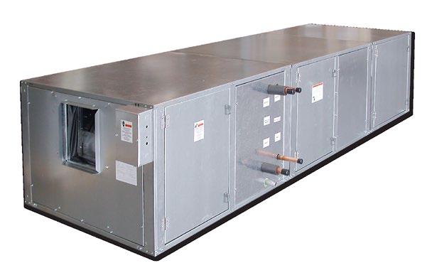
3 PRODUCT OVERVIEW The Perfect Solution for Schools, Hospitals, and Commercial Buildings. The flexibility of the Model MQL Air-Handling Unit allows you to design the unit to meet the specific project needs. The MQL design allows you to configure draw thru applications in horizontal, vertical, and footprint- saving arrangements. From basic air-handling to the sophisticated isolation room systems required to meet challenging indoor air quality (IAQ), controls, and acoustic (sound sensitive) projects the Model MQL Air-Handling Unit is your solution! STANDARD FEATURES Modular construction allows for footprint saving arrangements including stacking modules in two-high configuration. IAQ galvanized drain pans are double sloped to prevent standing water and minimize microbial growth. Stainless steel drain pans are available. Removable access panels for improved accessibility, cleanability, and serviceability. Hinged access doors with quick action latches are available. Single point power connection even with electric heat simplifies installation. Fan motors are factory mounted and wired to the junction box. Available in nine sizes, from 600 to 9,000 CFM. Internal spring isolation standard on all unit sizes Single wall and double wall-galvanized construction are available. Double wall construction enhances indoor air quality, protects insulation, and provides the ability to clean the inside of the unit. OPTIONAL FEATURES Factory-packaged air-handling units are available with starters or variable frequency drives, factory mounted and wired. Simply connect power, piping, and ductwork, and the units are ready for operation. An excellent way to minimize installation time, coordination and costs, while increasing reliability. Quiet, flexible, acoustical discharge plenums may be used for sound sensitive projects. Customized Options including: - Direct drive plenum fans - High efficiency filters - 15 and 30 access panels ENVIRO-TEC 3
4 FEATURES AND BENEFITS DESIGNED FOR MAXIMUM FLEXIBILITY The ENVIRO-TEC Model MQL Air-Handling Unit is designed to maximize flexibility of selection and installation. The unit is also designed to exceed the stringent quality standards of the institutional market, while remaining cost competitive in the light commercial segment of the market. ENVIRO-TEC Model MQL sets the new standard for quality, flexibility, and competitive pricing. FOR THE BUILDING DESIGNER: OPTIONAL COMPONENTS MEAN FLEXIBILITY The extensive variety of standard options available on the MQL is where you find the versatility to fit any HVAC system designer s needs. Options include: Mixing boxes with standard low leak dampers, High efficiency filter sections for 2 prefilter and 4 final filter, blow thru electric heat with single point power connection. All electric heat units are listed with ETL as an assembly and carry the cetl label. High Efficiency motors, starters, disconnects and fusing mean easier coordination between mechanical and electrical trades. Coil options allow for up to 8 row cooling coils. Water coils have optional circuiting that can be used to reduce Water Pressure Drop, which may also allow for pipe size reductions and lower material cost. Hot Water or Standard Steam coils may be placed in the Preheat or Reheat position. All Model MQL Air-Handling Units have the option of foil faced insulation. FOR THE CONTRACTOR: LOWER INSTALLED COST Model MQL Air-Handling Units are shipped completely assembled, reducing field installation time and labor. All units are thoroughly inspected and tested prior to shipment, eliminating potential problems at startup. Motor wiring is brought to a junction box on the outside of the unit casing, reducing electrical hook-up time. A wide variety of fan discharge configurations allow for increased flexibility and easier installation on the jobsite, resulting in cost reductions by eliminating expensive elbows, etc. FOR THE OWNER: QUALITY PRODUCT Model MQL Air-Handling Units are built from G60 minimum spangled galvanized steel with a chromate coating. This metal surpasses the ASTM 125 hour salt spray test for corrosion and rust. Standard insulation is 1 inch fiberglass insulation which is glued and pin spotted for maximum positive adhesion. Insulation complies with UL 181 and NFPA 90A. All units, with or without Electric Heat, are ETL listed and labeled. All wiring is in compliance with NEC, assuring safety and quality for the owner. 4 ENVIRO-TEC
5 APPLICATION CONSIDERATIONS Model MQL Air-Handling Units offer a wide range of application flexibility, while maintaining a simple, easy to install unit design. These units are intended to provide comfort cooling and heating within a small footprint. They may be applied in many types of building structures including schools, office buildings, hospitals, condominiums, assisted living facilities, apartments or stores. Applications can be constant or variable volume. There are many applications in which the MQL product can be utilized. Some examples include: Constant volume applications Two-pipe hydronic system for cooling and/or heating Two-pipe hydronic cooling system with electric heat Four-pipe system with dedicated heating and cooling coils Direct Expansion (DX) split systems with hydronic heat Direct Expansion (DX) split systems with electric heat Variable volume applications Two-pipe hydronic system for cooling and/or heating. Two-pipe hydronic cooling system with electric heat. Four-pipe system with dedicated heating and cooling coils. ACOUSTICS Control of noise within both occupied and unoccupied spaces has become increasingly important to designers and building owners/ occupants. Proper consideration must be given to placement of indoor air conditioning units, particularly in the occupied space. Inherent flexibility of the fan and coil combination in the vertical configuration allows application in sound-sensitive areas. In such instances, a fan running at low speed with a high capacity coil normally yields satisfactory results. It also may be desirable to select a larger nominal capacity unit and operate it at a less than nominal airflow for further acoustic benefit. Three phase motors are recommended for soundsensitive applications to avoid potential single phase motor hum. Unit operation in the stall region of the fan curve is not recommended since it may cause unsatisfactory noise levels and excessive unit vibration. INSTALLATION These floor mounted or ceiling hung units can be installed on a base rail or hanger rods at the corner points. All units have internally isolated fan decks; therefore, flex connections are not required, which will reduce installation costs. One of the most important and basic IAQ issues is condensate management. The first step to ensure trouble-free operation is proper installation. It is very important that the unit be mounted high enough so that the condensate drain from the unit may be properly trapped. Please refer to the MQL IOM Manual at for specifics on this issue. As with all HVAC systems, these units should be installed according to all applicable ASHRAE standards, SMACNA and local code requirements. OPERATING LIMITATIONS Units must not be operated above maximum fan speed or unit airflow as listed in the Fan Performance section of this catalog. Unit operation at greater than maximum fan speed could drastically reduce bearing life and may result in a catastrophic failure. Operating at greater than the maximum allowable airflow in the cooling mode may result in unsatisfactory operation due to moisture carry over from the coil. In addition, it is often not economical to operate a unit at its maximum fan speed due to the greater motor power requirements. Units with electric heat should not be operated with leaving air temperature greater than 104 F, to prevent excessive leaving air temperatures and electric heat limit trips. A hydronic (or steam) coil and electric heat should not be operated simultaneously to prevent excessive leaving air temperatures and limit trips. Electric heat units are equipped with a lockout switch that disables the electric heater if the temperature of the hydronic (or steam) coil is greater than 104 F (40 C). Water coils must not be operated above a fluid velocity of 8 ft./sec. to reduce the possibility of velocity induced erosion and flow noise. Water coils must not be operated below a fluid velocity of 1 ft./sec. to prevent degraded coil performance caused by laminar flow. These high or low fluid flow rates may not be included in the AHRI coil certification. ENVIRO-TEC 5
6 UNIT CONFIGURATION Fig.1 Fig.2 Fig.2 Fig.2 Fig.4 Fig.4 Fig.5 Air Flow UNIT CONFIGURATION(IN DIRECTION OF AIRLFOW) Upper Deck - B Lower Deck - A Position MQL- Module Size Dim EFM External Flat Filters (2 ) H - in (m m ) W - in (m m ) L - in (m m ) 17-3/8 (441) 28 (711) 5-1/4 (133) 17-3/8 (441) 34 (864) 5-1/4 (133) 17-3/8 (441) 42 (1069) 5-1/4 (133) 26-3/8 (670) 42 (1069) 5-1/4 (133) 26-3/8 (670) 46 (1168) 5-1/4 (133) 26-3/8 (670) 56 (1422) 5-1/4 (133) 41-3/16 (1046) 64 (1626) 5-1/4 (133) 41-3/16 (1046) 68 (1727) 5-1/4 (133) 41-3/16 (1046) 80 (2032) 5-1/4 (133) SAM SCM SFM Small Access Small Coil Small Flat Filters (2 and/or 4 Cartridge) H - in (m m ) W - in (m m ) L - in (m m ) 15 (381) 36 (914) 15 (381) 15 (381) 15 (381) 34 (864) 48 (1219) 15 (381) 34 (864) 58 (1473) 15 (381) 66 (1676) 15 (381) 70 (1778) 15 (381) 82 (2083) 15 (381) MAM MCM MFM MIM MMM MRM MVM Medium Access Medium Coil Med. INTELLITRAC Mix. Box w/flat Filters (2 ) Med. INTELLITRAC Inlet Plenum w/flat Filters (2 ) Medium Mixing Box with Flat Filters (2 ) Medium Inlet Plenum with Flat Filters (2 ) Medium V-Bank Filters (2 ) H - in (m m ) W - in (m m ) L - in (m m ) 36 (914) 34 (864) 48 (1219) 34 (864) 58 (1473) 66 (1676) 70 (1778) 82 (2083) HFM HPM VCM VFM Horizontal FC Fan Horizontal Plug Fan Vertical Coil Vertical FC Fan H - in (m m ) W - in (m m ) L - in (m m ) 32 (813) 36 (914) 32 (813) 32 (813) 36 (914) 34 (864) 48 (1219) 36 (914) 34 (864) 58 (1473) 36 (914) 66 (1676) 40 (1016) 70 (1778) 40 (1016) 82 (2083) 40 (1016) LFM LIM LMM LRM LPM Lg. INTELLITRAC Mix. Box w/v-bank Filters (2 ) Lg. INTELLITRAC Inlet Plenum w/v-bank Filters (2 ) Large Mixing Box with V-Bank Filters (2 ) Large Inlet Plenum with V-Bank Filters (2 ) Large Discharge Plenum H - in (m m ) W - in (m m ) L - in (m m ) 42 (1067) 36 (914) 42 (1067) 42 (1067) 42 (1067) 34 (864) 48 (1219) 42 (1067) 34 (864) 58 (1473) 42 (1067) 66 (1676) 42 (1067) 70 (1778) 42 (1067) 58 (1473) 42 (1067) FCM FC Fan and Coil Combination (Horizontal Only) H - in (m m ) W - in (m m ) 36 (914) 34 (864) 48 (1219) 34 (864) 58 (1473) 66 (1676) 70 (1778) 82 (2083) EHB Electric Heat Blow Thru H - in (m m ) W - in (m m ) L - in (m m ) 13-1/2 (343) 11-1/2 (292) 13-1/2 (343) 11-1/2 (292) 13-1/2 (343) 11-1/2 (292) 18 (457) 17 (432) 18 (457) 17 (432) 18 (457) 17 (432) 21 (533) 24 (610) 21 (533) 24 (610) 21 (533) 24 (610) Notes: 1. All dimensions are ± 1/4 (6mm). Metric values are soft conversions. 2. Section images are for identification of unit configuration only. See individual section submittal drawings at for details. 3. Certain configuration rules apply; see catalog and selection program for details. 4. All data subject to change without notice. 6 ENVIRO-TEC
7 ELECTRIC HEAT STANDARD FEATURES G60 galvanized steel casing Flanged construction for direct unit mounting, in blow thru configuration Listed for zero clearance installation Meets National Electrical Code requirements Ni-Chrome wire in ceramic insulators Stainless steel element terminals and hardware Element support brackets on maximum 3 1/2" centers Solid cover with continuous full height hinge Overtemperature protection All internal wiring rated for 105 C minimum Airflow switch Incoming line power distribution block ETL Listed in compliance with UL/ANSI Standard 1995 Single point power connection Heater factory mounted to unit with ETL listing as an assembly OPTIONAL FEATURES Main incoming power disconnect (non-fused) (fused) Fusing (main) (per stage) Magnetic contactors wired for disconnecting operation Solid state relay with 4-20 ma or 2-10 VDC control Fan control package with heater interlock contacts (required for single point power connection) De-rated elements (for longer life) Side View Front View Airflow Blow Thru (installed on unit discharge) HEATER AMP CALCULATION VOLTAGE 115/1 208/1 230/1 277/1 208/3 230/3 460/3 575/3 AMPs per kw Non-Fused Door Interlock Disconnect Switch shall be sized according to MCA. 2. Fused Door Interlock Disconnect Switch and Main Fusing shall be sized according to MOP. 3. Heaters above 480v must utilize one time secondary limits only. ENVIRO-TEC 7
8 UNIT VOLTAGE AND PHASE Single Phase Three Phase BLOW-THRU ELECTRIC HEAT Unit Size Min Max Min Max Min Max Min Max Min Max Min Max Min Max Min Max Min Max kw AMPs kw AMPs kw AMPs kw AMPs kw AMPs kw AMPs kw AMPs kw AMPs Notes: 1. Blow thru heaters can have a maximum of two stages. 2. VFD controllers cannot be supplied with blow thru heaters. 3. Specific kw ratings are available within the ranges shown. Refer to selection program. 4. Heaters above 480v must utilize one time secondary limits only. 8 ENVIRO-TEC
9 COIL AND FILTER DATA ENVIRO-TEC offers hot water, chilled water, direct expansion (DX), and standard steam coils for specific application with all Model MQL air-handling units. Coils tested in accordance with AHRI 410, and strict on-site inspection before, during, and after installation guarantees the highest quality and performance available. Standard Features All coils are designed, manufactured and tested by ENVIRO-TEC. 1/2 O.D. seamless copper tubes. Aluminum fin construction with die-formed spacer collars for uniform \spacing. Mechanically expanded copper tubes leak tested to a minimum 450 PSIG air pressure under water. Manual air vent plug on all water coils. Copper ODM sweat connections. 450 PSIG working pressure at 200 F. Refrigerant coils are factory sealed and charged with a minimum of 5 PSIG nitrogen or refrigerated dry air. Steam coils rated at maximum for 15 PSIG tube wall thickness (0.025 on steam). Optional Features Stainless steel coil casings. Automatic air vents on water coils. Elevated working pressure ratings. Heat pump compatible cooling coils. Double circuit DX coils (50-50 split) tube wall thickness. The factory does not provide any metering device on DX coils, including fixed orifices or thermal expansion valves. COIL AND FILTER DATA UNIT SIZES Coil Face Area Qty. Flat Filters Dimensions Face Area Qty. V-Bank Filters Dimensions Face Area [0.20] 1 16x20x2 [406x508x51] 2.2 [0.20] 2 16x20x2 [406x508x51] 4.4 [0.41] [0.27] 1 16x25x2 [406x635x51] 2.8 [0.26] 2 16x25x2 [406x635x51] 5.6 [0.52] [0.35] 2 16x20x2 [406x508x51] 4.4 [0.41] 2 20x25x2 [508x635x51] 6.9 [0.64] [0.52] 2 20x25x2 [508x635x51] 6.9 [0.64] 4 20x20x2 [508x508x51] 11.1 [1.03] [0.69] 2 20x25x2 [508x635x51] 6.9 [0.64] x20x2 [406x508x51] 20x25x2 [508x635x51] 11.4 [1.06] [0.90] x25x2 [406x635x51] 20x25x2 [508x635x51] 9.7 [0.90] x20x2 [406x508x51] 20x20x2 [508x508x51] 15.6 [1.45] [1.17] 4 20x25x2 [508x635x51] 13.9 [1.29] 6 20x25x2 [508x635x51] 20.8 [1.93] [1.33] 8 16x20x2 [406x508x51] 17.8 [1.65] x25x2 [508x635x51] 20x20x2 [508x508x51] 27.1 [2.52] [1.58] 6 20x25x2 [508x635x51] 20.8 [1.93] 12 20x20x2 [508x508x51] 33.3 [3.09] Notes: 1. Standard filters are 2 throwaway; optional filters are 2 pleated. 2. Filter sizes are nominal and standard size, measured in inches [millimeters]. 3. Coil and filter face areas are measured in square feet [square meters]. 4. Cooling and heating coils have same face area. 5. For coil connection sizes, refer to the ENVIRO-TEC Selection Program. ENVIRO-TEC 9
10 STATIC PRESSURE DATA Unit Size CFM Mixing Box MFM LFM MMM LMM Economizer HEM Fan Modules FCM SECTION PRESSURE DROPS COMPONENT AIR PRESSURE DROP (IN. W.G.) RFM VFM Cabinet Losses SFM MVM Coil Modules SAM SCM MCM VCM MAM LAM Filter Modules Access Modules Plenum Module LPM Damper Losses Mixing Box MFM LFM MMM LMM Economizer Electric Heater Losses Blow Thru Draw Thru HEM EHB EHD Notes: 1. Figures do not include pressure drop of internal filter media. Refer to Air Pressure Drop Through Filter Section table for filter air pressure drop adders. 2. Figures do not include pressure drop of internal heating and/or cooling coils. Refer to Air Pressure Drop Through Dry Coil Section table for coil air pressure drop adders. 3. Mixing box with single damper in fully opened position operating at 100% air volume. 4. Economizer with outside air and exhaust dampers in fully opened position operating at 100% air volume. 10 ENVIRO-TEC
11 Filter Type High Efficiency Pleated Size & Efficiency FILTER PRESSURE DROPS Air Velocity (FPM) % % % % Notes: 1. Figures listed represent air pressure drop of clean filters. 2. Usable pressure drop across pleated media not recommended to exceed 1.0 inch w.g. 3. Air velocities associated with pressure drops in the shaded region not recommended. Rows Fins per Inch COIL PRESSURE DROPS AIR PRESSURE DROP THROUGH DRY COIL SECTION (IN. W.G.) Air Velocity (FPM) Note: Dehumidifying cooling coils with face velocities exceeding 525 fpm not recommended. ENVIRO-TEC 11
12 WEIGHT DATA UNIT SIZE COIL ROWS Coil Weight Data COIL WEIGHTS DRY COIL 100% WATER 40% GLYCOL 8 FPI 10 FPI 12 FPI 14 FPI 8 FPI 10 FPI 12 FPI 14 FPI 8 FPI 10 FPI 12 FPI 14 FPI 1 10 [5] 11 [5] 11 [5] 11 [5] 12 [5] 12 [5] 13 [6] 13 [6] 12 [5] 12 [5] 13 [6] 13 [6] 2 16 [7] 16 [7] 17 [8] 18 [8] 19 [9] 20 [9] 21 [10] 21 [10] 20 [9] 20 [9] 21 [10] 22 [10] 3 21 [10] 22 [10] 23 [11] 24 [11] 27 [12] 28 [13] 29 [13] 30 [14] 27 [12] 28 [13] 29 [13] 30 [14] 4 28 [13] 29 [13] 30 [14] 32 [14] 35 [16] 36 [16] 37 [17] 39 [18] 35 [16] 36 [16] 38 [17] 39 [18] 6 40 [18] 42 [19] 44 [20] 46 [21] 51 [23] 53 [24] 55 [25] 57 [26] 51 [23] 53 [24] 55 [25] 58 [26] 8 57 [26] 61 [28] 65 [30] 69 [31] 71 [32] 75 [34] 79 [36] 83 [38] 72 [33] 76 [34] 80 [36] 84 [38] 1 13 [6] 13 [6] 13 [6] 14 [6] 15 [7] 16 [7] 16 [7] 17 [8] 15 [7] 16 [7] 16 [7] 17 [8] 2 19 [9] 20 [9] 21 [10] 22 [10] 24 [11] 25 [12] 26 [12] 27 [12] 25 [11] 26 [12] 27 [12] 28 [13] 3 26 [12] 28 [13] 29 [13] 31 [14] 34 [15] 35 [16] 37 [17] 38 [17] 34 [15] 36 [16] 37 [17] 39 [17] 4 34 [15] 36 [16] 38 [17] 40 [18] 44 [20] 46 [21] 48 [22] 50 [23] 44 [20] 46 [21] 48 [22] 50 [23] 6 50 [23] 53 [24] 56 [25] 59 [27] 64 [29] 67 [31] 70 [32] 73 [33] 65 [20] 68 [31] 71 [32] 74 [34] 8 71 [32] 76 [34] 81 [37] 86 [39] 89 [41] 95 [43] 100 [45] 105 [47] 91 [41] 96 [43] 101 [46] 106 [48] 1 15 [7] 15 [7] 16 [7] 17 [8] 18 [8] 18 [8] 19 [9] 20 [9] 18 [8] 19 [9] 19 [9] 20 [9] 2 23 [11] 24 [11] 26 [12] 27 [12] 29 [13] 30 [14] 32 [15] 33 [15] 30 [13] 31 [14] 32 [15] 33 [15] 3 32 [14] 33 [15] 35 [16] 37 [17] 40 [18] 42 [19] 44 [20] 46 [21] 41 [19] 43 [19] 45 [20] 47 [21] 4 41 [19] 44 [20] 46 [21] 49 [22] 53 [24] 55 [25] 58 [26] 60 [27] 54 [24] 56 [25] 59 [27] 61 [28] 6 60 [27] 64 [29] 68 [31] 72 [33] 78 [35] 82 [37] 86 [39] 89 [41] 79 [36] 83 [38] 87 [39] 90 [41] 8 80 [36] 85 [38] 90 [41] 95 [43] 103 [47] 108 [49] 113 [51] 118 [54] 105 [47] 110 [50] 115 [52] 120 [54] 1 19 [9] 20 [9] 21 [10] 22 [10] 24 [11] 25 [11] 26 [12] 27 [12] 24 [11] 25 [11] 26 [12] 27 [12] 2 32 [14] 34 [15] 36 [16] 38 [17] 41 [19] 43 [20] 45 [20] 47 [21] 42 [19] 43 [20] 45 [20] 47 [21] 3 45 [20] 48 [22] 50 [23] 53 [24] 58 [26] 61 [28] 64 [29] 67 [30] 59 [27] 62 [28] 65 [29] 67 [30] 4 59 [27] 62 [28] 66 [30] 70 [32] 76 [35] 80 [36] 84 [38] 88 [40] 77 [35] 81 [37] 85 [39] 89 [40] 6 87 [39] 92 [42] 98 [44] 104 [47] 113 [51] 119 [54] 124 [56] 130 [59] 115 [52] 120 [55] 126 [57] 132 [60] [53] 125 [57] 133 [61] 142 [64] 152 [69] 160 [73] 169 [77] 177 [80] 155 [70] 163 [74] 171 [78] 179 [81] 1 23 [11] 25 [11] 26 [12] 27 [12] 30 [14] 31 [14] 32 [15] 33 [15] 30 [14] 31 [14] 32 [15] 34 [15] 2 40 [18] 43 [19] 45 [20] 48 [22] 52 [24] 54 [25] 57 [26] 59 [27] 53 [24] 55 [25] 58 [26] 60 [27] 3 57 [26] 61 [27] 64 [29] 68 [31] 75 [34] 78 [36] 82 [37] 86 [39] 76 [34] 79 [36] 83 [38] 87 [39] 4 75 [34] 80 [36] 85 [38] 90 [41] 98 [45] 103 [47] 108 [49] 113 [51] 100 [45] 105 [47] 110 [50] 115 [52] [50] 118 [54] 126 [57] 133 [60] 146 [66] 153 [69] 161 [73] 168 [76] 148 [67] 155 [70] 163 [74] 170 [77] [71] 169 [77] 182 [83] 195 [88] 204 [92] 216 [98] 229 [104] 241 [110] 207 [94] 219 [99] 232 [105] 245 [111] 1 28 [13] 30 [13] 31 [14] 33 [15] 36 [16] 37 [17] 39 [18] 40 [18] 36 [16] 38 [17] 39 [18] 41 [18] 2 48 [22] 51 [23] 54 [25] 57 [26] 63 [28] 66 [30] 69 [31] 72 [33] 64 [29] 67 [30] 70 [32] 73 [33] 3 68 [31] 73 [33] 77 [35] 82 [37] 90 [41] 95 [43] 99 [45] 104 [47] 91 [41] 96 [44] 101 [46] 106 [48] 4 89 [41] 96 [43] 102 [46] 108 [49] 119 [54] 125 [57] 131 [60] 138 [62] 120 [55] 127 [58] 133 [60] 139 [63] [60] 142 [64] 152 [69] 161 [73] 176 [80] 186 [84] 195 [88] 204 [93] 179 [81] 188 [85] 198 [90] 207 [94] [83] 197 [90] 212 [96] 226 [103] 241 [109] 255 [116] 270 [122] 284 [129] 244 [111] 259 [117] 273 [124] 288 [131] 1 35 [16] 37 [17] 39 [18] 42 [19] 45 [21] 48 [22] 50 [23] 52 [24] 46 [21] 48 [22] 50 [23] 52 [24] 2 62 [28] 66 [30] 70 [32] 74 [34] 81 [37] 86 [39] 90 [41] 94 [43] 83 [38] 87 [39] 91 [41] 95 [43] 3 88 [40] 94 [43] 101 [46] 107 [49] 118 [53] 124 [56] 130 [59] 137 [62] 119 [54] 126 [57] 132 [60] 139 [63] [53] 125 [57] 133 [60] 142 [64] 155 [70] 164 [74] 172 [78] 181 [82] 158 [72] 166 [75] 175 [79] 184 [83] [78] 186 [84] 199 [90] 211 [96] 231 [105] 244 [111] 257 [117] 270 [122] 235 [107] 248 [112] 261 [118] 274 [124] [106] 251 [114] 269 [122] 287 [130] 311 [141] 329 [149] 347 [157] 365 [165] 316 [143] 334 [151] 352 [160] 370 [168] 1 39 [18] 41 [19] 44 [20] 46 [21] 50 [23] 53 [24] 55 [25] 58 [26] 51 [23] 54 [24] 56 [25] 58 [26] 2 69 [31] 74 [33] 78 [36] 83 [38] 91 [41] 96 [43] 101 [46] 106 [48] 92 [42] 97 [44] 102 [46] 107 [49] 3 98 [45] 106 [48] 113 [51] 120 [55] 132 [60] 139 [63] 146 [66] 154 [70] 134 [61] 141 [64] 149 [67] 156 [71] [59] 140 [63] 149 [68] 159 [72] 174 [79] 184 [83] 194 [88] 203 [92] 177 [80] 187 [85] 197 [89] 206 [94] [88] 208 [94] 223 [101] 237 [108] 260 [118] 274 [124] 289 [131] 303 [138] 264 [120] 279 [126] 293 [133] 308 [140] [123] 295 [134] 318 [144] 341 [155] 359 [163] 382 [173] 405 [184] 428 [194] 365 [166] 388 [176] 411 [186] 434 [197] 1 45 [20] 48 [22] 51 [23] 53 [24] 58 [26] 61 [28] 64 [29] 67 [30] 59 [27] 62 [28] 65 [29] 68 [31] 2 79 [36] 85 [39] 91 [41] 97 [44] 106 [48] 112 [51] 117 [53] 123 [56] 108 [49] 113 [51] 119 [54] 125 [57] [52] 122 [56] 131 [59] 140 [63] 153 [69] 162 [73] 170 [77] 179 [81] 155 [71] 164 [74] 173 [78] 181 [82] [68] 162 [73] 173 [79] 185 [84] 203 [92] 214 [97] 226 [102] 237 [108] 206 [93] 217 [99] 229 [104] 240 [109] [102] 241 [109] 259 [117] 276 [125] 302 [137] 319 [145] 336 [153] 354 [160] 307 [139] 324 [147] 341 [155] 359 [163] [93] 206 [93] 206 [93] 206 [93] 309 [140] 309 [140] 309 [140] 309 [140] 315 [143] 315 [143] 315 [143] 315 [143] NOTE: Unit weight data is shipping weight in pounds [kilograms]. 12 ENVIRO-TEC
13 WEIGHT AND ELECTRICAL DATA MOTOR/DRIVE WEIGHT DATA MOTOR WEIGHTS MOTOR MOTOR HORSEPOWER TYPE 1/3 1/2 3/ / / ODP 25 [11] 28 [13] 30 [762] 35 [16] 45 [20] 35 [16] 75 [34] 100 [45] 125 [57] 125 [57] 220 [100] TEFC 28 [13] 35 [16] 33 [338] 45 [20] 65 [29] 70 [32] 85 [39] 105 [48] 145 [66] 160 [73] 295 [134] E+ N/A N/A N/A 40 [18] 55 [25] 55 [25] 90 [41] 100 [45] 145 [66] 130 [59] 300 [136] 2 SPEED 45 [20] 35 [16] 33 [338] 45 [20] 40 [18] 70 [32] 75 [34] N/A N/A N/A N/A Notes: 1. Includes motor, pulleys, belts, and motor base. 2. Motor/drive weight data is shipping weight in pounds [kilograms]. MOTOR ELECTRICAL DATA MAXIMUM MOTOR AMPERAGE HORSEPOWER VOLTAGE 115/1 208/1 230/1 277/1 208/3 230/3 460/3 575/3 1/ / / / / NOTES: 1. Actual motor nameplate AMPs may vary, but will not exceed values shown. 2. Consult factory for applications requiring special motors. GENERAL FAN NOTES Forward curved Fans (Belt Drive) 1. Consult factory for applications at operating conditions not in the following table and curves. 2. Fan motor voltage, fan rotation, and fan RPM may require field setting/adjustment. 3. Drive losses not included in fan performance table and curves. 4. In direction of airflow, after fan discharge only LPM (Large Plenum) and EHB (Electric Heat Blow Thru) are available. 5. Section will have internal isolation. Plenum Fans (Direct Drive) 1. Consult factory for applications at specific operating conditions. 2. VFD s are recommended for operation and field balancing of units whether factory supplied and factory mounted, field supplied and factory mounted, or field supplied and field mounted. 3. In direction of airflow, there must be space prior to the plug fan inlet. For sizes 02 through 06, the minimum requirement is either an SAM (Small Access) or an MCM (Medium Coil). For sizes 08 through 17, the minimum requirement is an MAM (Medium Access). 4. Section will have internal isolation. ENVIRO-TEC 13
14 FAN PERFORMANCE DATA Forward Curved Fan Performance Data TSP (in-wg) UNIT SIZE Actual CFM RPM BHP RPM BHP RPM BHP RPM BHP RPM BHP RPM * BHP * RPM * * * * * 790 * * * * BHP * * * * * 0.24 * * * * UNIT TSP SIZE (in-wg) Actual CFM RPM BHP RPM BHP RPM BHP RPM BHP RPM BHP RPM * * * * BHP * * * * 0.5 RPM 690 * * * * 670 * * * * * * * * * BHP 0.42 * * * * 0.54 * * * * * * * * * UNIT TSP SIZE (in-wg) Actual CFM RPM 1095 BHP RPM BHP RPM BHP RPM BHP RPM BHP RPM * * * BHP * * * 0.5 RPM 420 * * * * * * * 450 * * * * BHP 0.63 * * * * * * * 1.01 * * * * * Contact Factory 14 ENVIRO-TEC
15 FAN PERFORMANCE CURVES MQL02 (Fan Class I) MQL03 (Fan Class I) ENVIRO-TEC 15
16 MQL04 (Fan Class I) MQL06 (Fan Class I) 16 ENVIRO-TEC
17 MQL08 (Fan Class I) MQL10 (Fan Class I) ENVIRO-TEC 17
18 MQL12 (Fan Class I) MQL12 (Fan Class II) 18 ENVIRO-TEC
19 MQL14 (Fan Class I) MQL14 (Fan Class II) ENVIRO-TEC 19
20 MQL17 (Fan Class I) MQL17 (Fan Class II) 20 ENVIRO-TEC
21 MQL Modular Air-Handling Units FORM ET EG1 (517) MQL02 (Fan Class I) MQL03 (Fan Class I) ENVIRO-TEC 21
22 MQL Modular Air-Handling Units FORM ET EG1 (517) MQL04 (Fan Class I) MQL06 (Fan Class I) 22 ENVIRO-TEC
23 MQL Modular Air-Handling Units FORM ET EG1 (517) MQL08 (Fan Class I) MQL10 (Fan Class I) ENVIRO-TEC 23
24 MQL Modular Air-Handling Units FORM ET EG1 (517) MQL12 (Fan Class I) MQL17 (Fan Class I) 24 ENVIRO-TEC
25 GUIDE SPECIFICATIONS Air-Handling Unit HVAC Guide Specifications - Section 15XXX Size Range: 600 9,000 CFM ENVIRO-TEC Model Number: MQL Part 1 General 1.01 SYSTEM DESCRIPTION A. Indoor mounted air-handling unit designed to provide air to a conditioned space as required to meet specified performance requirements for ventilation, heating, cooling, filtration and air distribution. Unit shall be assembled for draw thru application and shall be arranged to discharge conditioned air horizontally or vertically as shown on the contract drawings. B. Unit with a direct-expansion cooling coil shall have the capability to be used in a refrigerant circuit in conjunction with a field supplied and matched air-cooled condensing unit QUALITY ASSURANCE A. Coils shall be tested in accordance with AHRI 410 Standard for Forced-Circulation Air-Cooling and Air- Heating Coils. B. Direct expansion coils shall be designed and tested in accordance with ANSI/ASHRAE 15 Safety Code for Refrigeration Systems. C. Insulation and insulation adhesive shall comply with NFPA 90A and 90B requirements for flame spread and smoke generation. D. Unit shall be constructed in accordance with UL 1995 standards, comply with NEMA standards and shall carry the cetl label, display certification symbol on units of certified models. Installation of ancillary electrical components shall comply with NEC DELIVERY, STORAGE AND HANDLING Unit shall be stored and handled in accordance with the unit manufacturer s instructions. Part 2 Products 2.01 EQUIPMENT A. General: Factory assembled air-handling unit that is modular in design and construction. Unit may consist of a fan and coil section with factory-installed chilled water or direct expansion coil, preheat or reheat coil, heating coil section, filter section, combination filter/mixing box (flat or V-bank arrangement), economizer, or access section(s) as indicated on the equipment schedules. B. Unit Cabinet: 1. Unit panels shall be constructed of G60 galvanized steel and shall be capable of withstanding 125-hour salt spray test per ASTM Standard 117. All casing panels shall be removable for easy access to the unit. All panels shall be gasketed to ensure a tight seal. 2. Double wall unit panels (includes corner posts, mullions and access doors) shall be 1-in. nominal thickness using 1.5-lbs/ft 3 fiberglass insulation between galvanized steel panels. 3. Single wall unit panels shall be 1-in. nominal thickness using matt-faced fiberglass insulation with a nominal density of not less than 1.5-lbs/ft Insulation shall be secured to casing with water based adhesive and weld pins where necessary, corresponding to 25/50-flame spread/smoke developed. 5. Condensate drain pans shall be sloped to prevent standing water and shall be constructed of 18 gauge G60 galvanized steel or stainless steel; they shall have a galvanized steel or stainless steel male pipe threaded drain connection. ENVIRO-TEC 25
26 C. Fan Section: 1. Fan sections shall be constructed of G60 steel and shall have a formed channel base for integral mounting of fan, motor, and casing panels. Fan housing, wheel, shaft, and bearings shall be rigidly secured to the base unit. 2. Fan decks shall be internally spring isolated (one-inch deflection) with the fan outlet connection to be made using canvas duct. 3. Each unit shall have one fan wheel and housing only. 4. Fan wheels shall be designed for continuous operation at the maximum rated fan speed and motor horsepower. Fan wheels and shafts shall be selected to operate at least 25% below the first critical speed, and shall be statically and dynamically balanced as an assembly. 5. Fan shafts shall be solid steel, turned, ground and polished. 6. Fan bearings shall be a self-aligning, non-regreasable ball bearing type selected for an average life (L50) of 100,000 hours at design operation conditions, per ANSI Code B Fan motor shall be mounted within the fan section casing. Motor shall be NEMA Design B with sizes and electrical characteristics as shown on the equipment schedule. 8. Fan drive shall be designed for a minimum of 1.15 service factor and shall be factory mounted and aligned. Belt drive package shall be variable-pitch type (constant volume) or fixed-pitch type (variable volume). D. Coil Sections: 1. All coils shall have aluminum plate fins mechanically bonded to 1/2-in. OD seamless copper tubes by mechanical expansion. Coils shall be factory leak tested at 450 psig air pressure under water. Copper tubes shall be either or copper tube wall thickness. Coils shall have G60 galvanized steel or stainless steel casings with copper headers and sweat connections. 2. Chilled water coils shall have a working pressure of 450 psig at 200 F. No turbulence-promoting devices will be permitted inside the tubes. Headers shall have vent connections. 3. Direct-expansion coils shall be provided with pressure-type brass distributors with solder-type connections. Coils shall be designed and tested in accordance with ANSI/ASHRAE Hot water coils shall have a working pressure of 450 psig at 200 F. No turbulence-promoting devices will be permitted inside the tubes. Headers shall have vent connections. 5. Steam distributing coils (standard single tube type) shall have a maximum working pressure of 15 psig at ambient temperatures above 35 F. Tube wall thickness shall be as standard. 6. Electric heat coils for use in blower coil units shall be open coil type, nichrome wire resistance elements, insulated by floating ceramic bushings. Thermal cutouts for primary and secondary over-temperature protection shall be provided to meet UL and NEC requirements. Maximum element watt density shall be 55-watts/sq inch. The manufacturer shall furnish an integral control box. It shall contain primary and secondary control thermal cutouts, relays, airflow switch, and fused control transformer. E. Filter Sections: 1. Each filter section shall be designed and constructed to house the specific type of filter specified on the equipment schedule. 2. Flat filter sections shall accept 2-in. 30% (MERV-8) pleated filters of standard sizes. Sections shall include side access slide rails. Flat filter section shall be arranged with minimum depth in direction of airflow. 3. Angle filter section shall accept 2-in. 30% (MERV-8) pleated filters of standard sizes arranged in horizontal V formation. Sections shall include side access slide rails. 26 ENVIRO-TEC
27 F. Damper Sections: 1. Mixing boxes, filter mixing boxes and economizers shall have parallel blade, interconnecting dampers. Damper blades shall have parallel bends for stiffness and shall be mechanically fastened to steel rods rotating in brass bushings and mounted in rigid galvanized steel frames. Dampers shall be sectionalized to limit blade width, minimize blade warpage, and ensure tight closure. 2. All dampers for mixing boxes and filter mixing boxes shall be rated with a leakage rate not to exceed 5% of air quantity calculated at 2000 fpm velocity though damper and 4.0-in.wg. pressure difference. Damper blades shall be gasketed and stainless steel perimeter-sealing strips shall be provided. Damper linkage shall be provided and installed with all mixing boxes. G. Access Sections: 1. Access sections shall be installed where indicated on the drawings and shall be as specified on the equipment schedule. 2. Access sections shall have removable access panels. H. Special Features The following unit options shall be available. 1. Fan Section: a. Variable frequency drives. b. Motor starters contactor with overload for three phase and contactor for single phase. c. High-efficiency motors (inverter-duty). d. Totally enclosed fan cooled (TEFC) motors (inverter-duty). e. Direct drive plenum fans with internal isolation. f. Class II forward curved fans with regreasable pillow block bearings. 2. Coil Section: a. Chilled water coil with copper plate fins and/or stainless steel casing. b. Direct-expansion coil with copper plate fins and/or stainless steel casing. c. Hot water coil with copper plate fins and/or stainless steel casing. d. Steam distributing coil with copper plate fins and/or stainless steel casing. 3. Filtration: a. 2 pleated filter type (standard size), 30-35% efficiency (MERV-8) b. 4 pleated filter type (standard size), 60-65% efficiency (MERV-11) c. 4 pleated filter type (standard size), 80-85% efficiency (MERV-14) d. 4 pleated filter type (standard size), 90-95% efficiency (MERV-15) 4. Access Doors: Hinged (lift-off type) doors with quick-action latches (handles) on both sides of the section for access to both the fan and filter from either side of the unit. 5. Base Rail: Unit mounted base rail shall be a minimum of 4 in height and constructed of galvanized steel, structurally capable of supporting unit on floor or by ceiling suspension. ENVIRO-TEC 27
28 I. End Devices: The following guide specifications should be used as a basis for design when using optional factory/fieldmounted direct digital controls. These specifications should be reviewed to match the specific system control requirements and available control packages. 1. The electrical components shall be recognized by UL. The unit shall be in compliance with the UL 1995 standards. Fan motors are wired and terminated in the control enclosure. 2. All application software performing the required control functions shall be field-supplied with the DDC controller factory or field mounted and wired (tested and configured). 3. Available End Devices and Controls: a. Variable Frequency Drives Factory supplied and mounted b. Motor Starters Factory supplied and mounted c. End Devices (factory supplied and mounted) Disconnect switch (fused or non-fused) Damper actuator (modulating from 100% OA to 100% RA) Fuses, relays, transformers, etc. Electric heat interlock relay Hand off auto switch 28 ENVIRO-TEC
29 METRIC CONVERSION CHART SI UNIT CONVERSION FACTOR = ENGLISH UNIT CONVERSION FACTOR = SI UNIT SI UNIT CONVERSION FACTOR = ENGLISH UNIT CONVERSION FACTOR = SI UNIT Area Temperature Interval cm mm 2 C 1.8 F C cm in mm 2 Velocity m ft m 2 m/s ft/s m/s Length m/s ft/min m/s mm in mm Volume mm ft mm mm 3 1.0x10⁻⁶ L m ft m mm x10-5 in L m yd m L ft L Mass m yd m 3 g oz g L U.S. gal L kg lb kg L U.S. pint L tonne, Mg U.S. ton (2000 lb.) tonne, Mg ml, cm U.S. oz ml Power Volume / Time kcal/h W m 3 /h L/s kcal/h Btu/h W m 3 /h ft 3 /min L/s HP metric kw m 3 /h U.S. gal/min L/s HP metric HP (550) kw L/h 2.778x10⁻⁴ L/s Mcal/h kw L/h 4.403x10⁻³ U.S. gal/min L/s Mcal/h Ton refr kw (m 3 /h)/ Pressure (1000 mm w.g Pa kcal/h) 4 C cfm/ton L/s - kw mm w.g. in H O 4 C 39.2 F Pa mm Hg kpa 0 C SI UNIT CONVERSION = ENGLISH CONVERSION = SI mm Hg FACTOR UNIT FACTOR UNIT in Hg 32 F kpa 0 C kgf/cm kpa Temperature kgf/cm psi kpa C C K mh 2 O ft H 2 O kpa C ( C x 1.8) + 32 F ( F - 32) 1.8 C PREFIXES LEGEND UNITS M MEGA m METER HP metric = METRIC HORSEPOWER k KILO cal CALORIE mm w.g. = MILLIMETERS WATER GAUGE d DECI 10-1 kg KILOGRAM (mass) mmce = MILLIMETERS WATER GAUGE c CENTI 10-2 kgf KILOGRAM - FORCE mmhg = MILLIMETERS MERCURY m MILLI 10-3 kp KILOGRAM - FORCE tonne = 1000 kg L LITER kcal = kilocalories C DEGREES CELSIUS bar = 100 KPa K W Pa J N h m s KELVIN WATT PASCAL JOULE NEWTON HOUR MINUTE SECOND ENVIRO-TEC 29
30 STANDARD & OPTIONAL FEATURES STANDARD FEATURES Construction Modular design facilitates retrofit Galvanized steel cabinet construction 1 thick fiberglass insulation, glued and pinned in place Gasketed, removable access panels sized for easy handling Left and right hand arrangement Access panels on all sections Fan Assembly Single forward-curved fan sections Statically and dynamically balanced Solid steel shafting Ball bearings with a minimum design average life (L50) of 100,000 hours Fan decks with internal vibration isolation Fan Motor and Drive Single speed ODP motors 1750 RPM single speed, 60 Hertz Single phase motors with inherent thermal protection Three phase motors Standard cross section V-belt drive with 1.2 service factor Adjustable pitch motor pulley and fixed pitch blower pulley Coils 1/2 O.D. seamless copper tubes G60 steel coil casings Collared aluminum fins Manual air vent plug on all water coils 450 PSIG Working Pressure at 200 F Copper ODM sweat connections tube wall on water and evaporator coils tube wall on steam coils Filters and Filter Rack Hinged side access flat filter rack 2 pleated filters (30%) Electrical Fan motor wired and terminated to junction box All units cetl listed in compliance with UL/ANSI 1995 Electric Heat Section Blow Thru configurations Factory mounted electric heater with single point power connection, ETL listed as an assembly OPTIONAL FEATURES Construction Double wall (solid or perforated) cabinets Stainless steel IAQ drain pan with stainless steel male pipe threaded connection Fan discharge arrangements Scrim reinforced foil faced insulation Hinged access panels with lift and turn fasteners 4 Base rails with rigging slots factory assembled and installed Fan Motor and Drive Direct drive plenum fans with internal rubber-in-shear (RIS) isolation TEFC motors High efficiency motors Variable frequency drives, factory installed (mounted and wired) Motor starter (contactor with overload for three phase; contactor for single phase), factory installed (mounted and wired) Return FC and plenum fan sections Coils 3, 4, 6 and 8 row chilled water or DX coils Up to 4 rows hot water or up to 2 rows standard steam Heating coil in preheat or reheat position Coil connections opposite handing Stainless steel coil casings tube wall thickness Auto air vents Filters and Filter Rack 4 high efficiency pleated filters (65, 85, and 95%) Mixing box with filter sections (flat or v-bank filter arrangements) Inlet Damper Section Factory assembled and installed Heavy gauge galvanized steel formed blade dampers Low leak dampers with extruded vinyl blade seals and flexible metal jamb seals Medium and large inlet plenums with v-bank or flat filters Parallel blade operation Interconnecting damper linkage Damper actuator (modulating from 100% OA to 100% RA) Additional Modules Discharge plenums Access sections Electrical Motor wiring in conduit Single phase fan control package Three phase fan control package Door interlocking disconnect switch (non-fused or fused) Fusing (main or per stage) Hand off auto switch (HOA) Frequency inverters Electric heat interlock relay Relays, transformers, etc. Catalog: ET EG1 (517) Supersedes ET EG1 (415) ENVIRO-TEC is a mark and/or registered mark. Unauthorized use is strictly prohibited Johnson Controls
PRODUCT CATALOG BLOWER COILS.
 2016 PRODUCT CATALOG BLOWER COILS www.superiorrex.com SBH / SBV Series Design Features DESIGNED FOR MAXIMUM FLEXIBILITY Both Horizontal and Vertical Belt Drive Blower Coils are designed to maximize flexibility
SSL & SBS Engineering Guide
 REDUCED-FOOTPRINT VERTICAL BLOWER COIL UNITS SSL & SBS Engineering Guide SO TOUGH, WE GUARANTEE IT. SSL SBS Table of Contents Features and Benefits... 3 Construction Features... 4 Features and Options...
SSL / SBS Sales Guide BLOWER-COILS REDUCED-FOOTPRINT, VERTICAL
 SO TOUGH, WE GUARANTEE IT. SSL / SBS Sales Guide BLOWER-COILS REDUCED-FOOTPRINT, VERTICAL SSL SBS www.superiorrex.com SSL / SBS Series: BIG ON FEATURES; SMALL IN SIZE Contractors All SSL/SBS model blower-coil
catalog CDV Fan-Coil Units High-Performance, Vertical
 catalog CDV Fan-Coil Units High-Performance, Vertical Catalog: ET115.26-EG8 (415) TABLE OF CONTENTS CDV Fan-Coil Units High-Performance, Vertical Features and Benefits... 3 Construction Features... 4 Standard
Horizontal and Vertical DIRECT DRIVE BLOWER COIL UNITS. Rating and selection at
 Horizontal and Vertical DIRECT DRIVE BER COIL UNITS Rating and selection at www.enviro-tec.com CDH/CDV TABLE OF CONTENTS Construction Features...3 Fan Assembly...4 Optional Construction...5 Electric Heat...6
FCC Fan-Coil Units High-Performance, Vertical
 FCC Fan-Coil s High-Performance, Vertical Model FCC construction features Piping and supply-duct connections are from top of unit, eliminating the need for side or back access Right or left-hand configurations
engineering guide FH Fan-Coil Units Low-Profile, Horizontal
 engineering guide FH Fan-Coil Units Low-Profile, Horizontal FORM 115.26-EG7 (908) Table of contents FH Fan-Coil Units Low-Profile, Horizontal Features and Benefits... Construction Features... Standard
Complete HVAC Capability. Central Station Air Handling Units. Publication No. WT-CSX-0616A
 Publication No. WT-CSX-0616A Central Station Air Handling Units Complete HVAC Capability Horizontal Draw-Thru to Size 65 Vertical Draw-Thru to Size 50 1000 to 60,000 CFM Forward Curved or Airfoil Wheels
Brown University Revised August 3, 2012 Facilities Design & Construction Standards SECTION AIR HANDLING UNITS
 SECTION 23 70 00 AIR HANDLING UNITS PART 1. GENERAL 1.1 Section includes air-handling units to 15,000 cfm and accessories. 1.2 Related Sections 1 : A. Division 01 - Brown University Standard for Narragansett
Chilled Water DOAS Fan Powered Terminal Units
 Chilled Water DOAS Fan Powered Terminal Units CHILLED WATER DOAS FAN POWERED TERMINAL UNITS DOAS TERMINAL UNITS FEATURES AND BENEFITS MINIMUM VENTILATION CONTROL The DOAS unit provides the Designer, Owner
A. American National Standards Institute (ANSI) : Establishes requirements applicable to certifying direct gas-fired heaters.
 : Establishes requirements applicable to certifying direct gas-fired heaters.") Section 15 _ Energy Recovery Air Handling System Part 1: GENERAL 1.1 Section Includes: A. Energy Recovery Air Handler B. Controls (most by Others) C. Equipment Schedule 1.2 Related Sections: A. Section
Section 15 _ Energy Recovery Air Handling System Part 1: GENERAL 1.1 Section Includes: A. Energy Recovery Air Handler B. Controls (most by Others) C. Equipment Schedule 1.2 Related Sections: A. Section
1.1 This section applies to air handling units for HVAC Systems.
 AIR HANDLING UNITS GENERAL INFORMATION 1.1 This section applies to air handling units for HVAC Systems. DESIGN REQUIREMENTS 2.1 Design Criteria a. The decision to use modular central station air handling
A. Section includes Factory Packaged, Modular units, providing cooling and heating for air distribution systems.
 15855 AIR HANDLING UNITS SPECIFIER: CSI MasterFormat 2004 number: 237313 PART 1 GENERAL 1.1 SUMMARY A. Section includes Factory Packaged, Modular units, providing cooling and heating for air distribution
SECTION AIR HANDLING UNIT
 SECTION 15800 - AIR HANDLING UNIT PART 1 - GENERAL 1.01 RELATED DOCUMENTS A. Basic Requirements: Provisions of Section 15010, BASIC MECHANICAL REQUIREMENTS, and Section 15030, ELECTRICAL REQUIREMENTS FOR
Modular Supply Make-Up Air Unit
 Modular Supply Make-Up Air Unit Model MSX Flexible Design Factory Assembled Heating Options Hot Water Steam Electric Cooling Options Evaporative Direct Expansion Chilled Water November 2009 Product Features
KINGS COUNTY JAIL EXPANSION PHASE III COUNTY OF KINGS SECTION
 SECTION 237433, PART 1 - GENERAL 1.1 RELATED DOCUMENTS A. Drawings and general provisions of the Contract, including General and Supplementary Conditions and Division 01 Specification Sections, apply to
WE ARE PLEASED TO PROVIDE THE ENCLOSED SUBMITTAL FOR YOUR REVIEW AND APPROVAL
 PREPARED FOR: DATE: JOB NAME: WE ARE PLEASED TO PROVIDE THE ENCLOSED SUBMITTAL FOR YOUR REVIEW AND APPROVAL EQUIPMENT DETAILS ITEM TAG DESCRIPTION MODEL NUMBER 1 2 3 4 5 6 7 8 9 10 11 12 13 14 15 EQUIPMENT
Guide Spec Summary. Option List. Date: 05/21/2001. EarthWise Modular Climate Changer Full Spec. Prepared by: Phone Number: Prepared for:
 Date: 05/21/2001 Time: 08:50:16 AM Job Name: EarthWise Modular Climate Changer Full Spec Location: Any Town, Earth Prepared by: Phone Number: Prepared for: Guide Spec Summary Option List SUBMITTALS Submittals
TECHNICAL GUIDE SPLIT-SYSTEM AIR-COOLED EVAPORATOR BLOWER 25, 30, 40 & 50 TON LA300, LB360, 480 & 600 (50 Hz) PROVEN PERFORMANCE GENERAL FEATURING
 PROVEN PERFORMANCE GENERAL FEATURING") TECHNICAL GUIDE SPLIT-SYSTEM AIR-COOLED EVAPORATOR BLOWER 25, 30, 40 & 50 TON LA300, LB360, 480 & 600 (50 Hz) PROVEN PERFORMANCE GENERAL The LA/LB line is a flexible performer. LA300, LB360 & 480 can be
TECHNICAL GUIDE SPLIT-SYSTEM AIR-COOLED EVAPORATOR BLOWER 25, 30, 40 & 50 TON LA300, LB360, 480 & 600 (50 Hz) PROVEN PERFORMANCE GENERAL The LA/LB line is a flexible performer. LA300, LB360 & 480 can be
Catalog Destiny Indoor Air Handler. Models Horizontal Configuration. Vertical Configuration
 Destiny Indoor Air Handler Models 002 030 Catalog 580-8 Horizontal Configuration Vertical Configuration Table of Contents Introduction.... 2 Certification...2 Smoke Control and Management Systems...2 Features
SPLIT-SYSTEM EVAPORATOR BLOWER DESCRIPTION FEATURES L4EU NOMINAL TONS
 036-21096-001 (0101) SPLIT-SYSTEM EVAPORATOR BLOWER L4EU240 20 NOMINAL TONS DESCRIPTION This 20 ton evaporator blower is designed with two distinct modules to provide maximum application flexibility. The
Modular Heating & Ventilating Unit Model IGX-HV
 Modular Heating & Ventilating Unit Model IGX-HV Indirect Gas-Fired Heating Evaporative Chilled Water DX Cooling October 2008 Product Features Model IGX-HV Indirect Gas-Fired Heating and Ventilating Unit
UNIVERSITY OF MISSOURI Central Station Air-Handling Units March
 GENERAL: 1. This section provides criteria for the design and installation of air handling units. DESIGN GUIDELINES: Design General 1. Location 1.1. For new construction, and existing buildings where possible,
SINGLE DUCT TERMINAL UNITS
 Performance Data AHRI Certification and Performance Notes Model Series 3000 asic Unit AHRI Certification Rating Points VAV: Fiberglass Inlet Size Airflow cfm l/s Min. Inlet Ps w.g. Pa Discharge Sound Power
AIR HANDLERS. Central Station (CS3) Roof Mounted (RT) (Modular AL Frame AHU)
 Roof Mounted (RT) (Modular AL Frame AHU)") AIR HANDLERS Central Station (CS3) (Modular AL Frame AHU) Roof Mounted (RT) CONTENTS 1. CS3 Modular Aluminium Frame AHU : Unit Types 2. Casing Structure 3. Blowers and Drives 4. Coils 5. Options and Accessory
AIR HANDLERS Central Station (CS3) (Modular AL Frame AHU) Roof Mounted (RT) CONTENTS 1. CS3 Modular Aluminium Frame AHU : Unit Types 2. Casing Structure 3. Blowers and Drives 4. Coils 5. Options and Accessory
SECTION PACKAGED ROOFTOP AIR CONDITIONING UNITS
 SECTION 15732 - PACKAGED ROOFTOP AIR CONDITIONING UNITS PART 1 - GENERAL 1.1 SECTION INCLUDES A. Package roof top unit. B. Heat exchanger. C. Refrigeration components. D. Unit operating controls. E. Roof
A. Air Handling Units shall be designed to the specific requirements of the application: Recirculation or 100% Makeup.
 SECTION 23 70 00- CENTRAL HVAC EQUIPMENT PART 1: GENERAL 1.1 PURPOSE: A. This standard is intended to provide useful information to the Professional Service Provider (PSP) to establish a basis of design.
SPLIT-SYSTEM EVAPORATOR BLOWERS K2EU060, K4EU090, K3EU120 & K1EU180 5 Thru 15 Nominal Tons DESCRIPTION ACCESSORIES FIELD INSTALLED
 (491) SPLIT-SYSTEM EVAPORATOR BLOWERS K2EU060, K4EU, K3EU & K1EU180 5 Thru 15 Nominal Tons DESCRIPTION These completely assembled units include a well-insulated cabinet, a DX cooling coil with copper tubes
AIR HANDLER SPECIFICATION
 AIR HANDLER SPECIFICATION Air Handlers AH-1 through 5 The following air handlers will be supplied: AH-1 FX15-4842 Series 5700 CFM AH-2 FX15-4236 Series 3990 CFM AH-3 FX15-3633 Series 2570 CFM AH-4 FX15-3330
SECTION AIR HANDLING UNITS WITH COILS. 1. Central Station Air Handling Units. 1. Section Basic Mechanical Requirements.
 SECTION 15855 AIR HANDLING UNITS WITH COILS PART 1 - GENERAL 1.01 SUMMARY A. Section Includes: 1. Central Station Air Handling Units. B. Related Sections: 1.02 REFERENCES 1. Section 15010 - Basic Mechanical
SECTION AIR COILS
 PART 1 - GENERAL 1.1 DESCRIPTION SECTION 23 82 16 AIR COILS SPEC WRITER NOTE: Delete between //---// if not applicable to project. Also delete any other item or paragraph not applicable in the section
UNIVERSITY OF ROCHESTER DESIGN STANDARDS NOVEMBER 1, 2013
 SECTION 15800 - AIR HANDLING EQUIPMENT 1.1 GENERAL A. All air handlers installed shall conform to the University of Rochester specification Guideline for Semi-Custom and Pre-Engineered Air Handling Units.
VariCool VAV Engineering Guide
 Engineering Guide Effective September 2017 Water-Cooled and Chilled Water, Variable Air Volume Contents Product Features... 3 UNIT FEATURES... 3 Product Features... 4 Marvel Plus Microprocessor Control
Technical Guide DESCRIPTION CHAMPION SPLIT-SYSTEM EVAPORATOR BLOWER L4EU240A 20 NOMINAL TONS (WORLD 50 HZ) FEATURES XTG-A-0307
 FEATURES XTG-A-0307") DESCRIPTION Technical Guide CHAMPION SPLIT-SYSTEM EVAPORATOR BLOWER L4EU240A 20 NOMINAL TONS (WORLD 50 HZ) This 20 ton evaporator blower is designed with two distinct modules to provide maximum application
DESCRIPTION Technical Guide CHAMPION SPLIT-SYSTEM EVAPORATOR BLOWER L4EU240A 20 NOMINAL TONS (WORLD 50 HZ) This 20 ton evaporator blower is designed with two distinct modules to provide maximum application
SECTION AIR DUCT ACCESSORIES
 SECTION 23 33 00 AIR DUCT ACCESSORIES PART 1 - GENERAL 1.1 SUMMARY A. Section includes back-draft dampers, combination fire-and-smoke dampers, duct access doors, fire dampers, smoke dampers, volume control
FLD = Furnished by Trane U.S. Inc. / Installed by Equipment Submittal Page 3 of 13
 Tag Data - Split System Air Conditioning Units (Large) (Qty: 6) Item Tag(s) Qty Description Model Number A1 20 ton vfd 6 6-25 Ton Unitary Split Systems ( SSC2 TTA24004H00-TWE240E404A TTA Air Condensing
CB18/CBS18 Bulletin # September 1994 Supersedes August 1986
 ENGINEERING DATA CB18 SERIES UP-FLOW CBS18 SERIES HORIZONTAL 2 To 5 Ton (7 To 18 kw) Nominal Cooling Capacity 7200 To 102 400 Btuh (2.1 To 30.0 kw) Optional Electrical Heat ENGINEERING DATA COILS MATCHED
SECTION PACKAGED ROOFTOP AIR CONDITIONING UNITS - CUSTOM
 SECTION 23 81 06 - PACKAGED ROOFTOP AIR CONDITIONING UNITS - CUSTOM PART 1 - GENERAL 1.1 SUMMARY A. This Section includes equipment types that contain all the components of the refrigeration process within
FAN POWERED VAV TERMINALS
 FAN POWERED VAV TERMINALS Models VFR, CFR and CFRQ INSTALLATION, OPERATION AND MAINTENANCE MANUAL All data herein is subject to change without notice. Refer to www.enviro-tec.com for current catalog data
SPLIT-SYSTEM EVAPORATOR BLOWER DESCRIPTION ACCESSORIES - FIELD INSTALLED. K5EU090 and K4EU Hz 7.5 and 10 NOMINAL TONS SUNLINE 2000 (WORLD 50 HZ)
") (994) SPLIT-SYSTEM EVAPORATOR BLOWER K5EU090 and K4EU120 50 Hz 7.5 and 10 NOMINAL TONS SUNLINE 2000 (WORLD 50 HZ) DESCRIPTION These completely assembled units include a well-insulated cabinet, a DX coil
(994) SPLIT-SYSTEM EVAPORATOR BLOWER K5EU090 and K4EU120 50 Hz 7.5 and 10 NOMINAL TONS SUNLINE 2000 (WORLD 50 HZ) DESCRIPTION These completely assembled units include a well-insulated cabinet, a DX coil
Advance Release September 2009
 Vertical Air Cooled DSV Series R 410A Model DSV096 DSV120 DSV144 DSV180 Nominal Cooling (Tons) 8 10 12 15 Refrigerant R 410A R 410A R 410A R 410A Cooling Performance Gross Cooling Capacity(Btu/h) 95,000*
CHAMPION SPLIT-SYSTEM EVAPORATOR BLOWER DESCRIPTION FEATURES L2EU NOMINAL TONS
 550.23-TG5Y (893) CHAMPION SPLIT-SYSTEM EVAPORATOR BLOWER L2EU240 20 NOMINAL TONS DESCRIPTION This 20 ton evaporator blower is designed with two distinct modules to provide maximum application flexibility.
SECTION AIR COILS
 PART 1 - GENERAL 1.1 RELATED DOCUMENTS A. Drawings and general provisions of the Contract, including General and Supplementary Conditions and Specification Sections, apply to this Section. B. Related Sections:
Large Capacity Fan Coil Units Catalog Belt-Drive and Direct-Drive Cabinet and Hideaway Models
 Large Capacity Fan Coil Units Catalog 735-12 Belt-Drive and Direct-Drive Cabinet and Hideaway Models Table of Contents Agency Listing and Nomenclature... 3 Overview....................................
Technical Guide SUNLINE 2000 DESCRIPTION ACCESSORIES FIELD INSTALLED SPLIT-SYSTEM EVAPORATOR BLOWER K4EU NOMINAL TONS (WORLD 50 HZ)
") Technical Guide SUNLINE 2000 SPLIT-SYSTEM EVAPORATOR BLOWER K4EU180 15 NOMINAL TONS (WORLD 50 HZ) DESCRIPTION These completely assembled units include a well-insulated cabinet, a DX cooling coil with copper
Technical Guide SUNLINE 2000 SPLIT-SYSTEM EVAPORATOR BLOWER K4EU180 15 NOMINAL TONS (WORLD 50 HZ) DESCRIPTION These completely assembled units include a well-insulated cabinet, a DX cooling coil with copper
Direct Fired Heater Model AD Specification
 Direct Fired Heater Model AD Specification Description A Direct-fired gas heating and ventilating unit(s), as indicated on the drawings shall be furnished. Unit(s) shall be tested in accordance with ANSI
DARTMOUTH COLLEGE DESIGN January 3, 2012 & CONSTRUCTION GUIDELINES
 SECTION 15856 MODULAR AIR HANDLING UNITS PART 1 DESIGN DIRECTIVES 1.1 QUALITY ASSURANCE A. NFPA Compliance: Modular air handling units and components shall be designed, fabricated, and installed in compliance
TECHNICAL GUIDE SPLIT-SYSTEM AIR-COOLED EVAPORATOR BLOWER 25, 30, 40 & 50 TON LA300, LB360, 480 & 600 PROVEN PERFORMANCE GENERAL FEATURING
 TECHNICAL GUIDE SPLIT-SYSTEM AIR-COOLED EVAPORATOR BLOWER 25, 30, 40 & 50 TON LA300, LB360, 480 & 600 PROVEN PERFORMANCE GENERAL The LA/LB line is a flexible performer. LA300, LB360 & 480 canbepositionedinupto12differentpositionsandsuspended
engineering guide FN Fan-Coil Units High-Performance, Horizontal
 engineering guide FN Fan-Coil Units High-Performance, Horizontal Form 115.26-EG3 (909) TABLE OF CONTENTS High-Performance, Horizontal Fan-Coil Units Features and Benefits...3 Unit Arrangements...4 Construction
VERTICAL STACK INNKEEPER GUIDE SPECIFICATION CGC Hybrid Heat Pump System
 VERTICAL STACK INNKEEPER GUIDE SPECIFICATION CGC Hybrid Heat Pump System PART 1 SYSTEM DESCRIPTION 1.1 The HVAC system is based on the CGC HYBRID Hydronic Heat Pump System. 1.2 The system will automatically
TYPICAL CPA SPECIFICATIONS
 TYPICAL CPA SPECIFICATIONS 4/10/2017 UNIT CONSTRUCTION: Casing: The exterior casing of the unit shall be constructed of 18-gauge, G235 galvanized steel (optional stainless steel or aluminum), unpainted.
MHCCW Chilled Water Ceiling Concealed With 5kW Electric Heat 2-Pipe Heat / Cool Fan Coil 30,000 BTUH
 MHCCW-10-05 Chilled Water Ceiling Concealed With 5kW Electric Heat 2-Pipe Heat / Cool Fan Coil 30,000 BTUH Rev. 1.21 HVAC Guide Specifications Chilled Water Fan Coil with Electric Heat 2-Pipe Nominal Size:
MHCCW Chilled Water Ceiling Concealed Without Electric Heat 2-Pipe Heat / Cool Fan Coil 18,000 BTUH
 MHCCW-06-00 Chilled Water Ceiling Concealed Without Electric Heat 2-Pipe Heat / Cool Fan Coil 18,000 BTUH Rev. 1.21 HVAC Guide Specifications Chilled or Hot Water Fan Coil 2-Pipe Nominal Size: 18,000 BTUH
TECHNICAL GUIDE. Description SPLIT-SYSTEM AIR-COOLED CONDENSING UNITS YD360, 480 & THRU 50 NOMINAL TONS YTG-B-0811
 Description These units are completely assembled, piped and wired at the factory to provide one-piece shipment and rigging. Each unit is pressurized with a holding charge of Refrigerant R-410A for storage
Internal ridged board 1" x 1.5 foil face installation shall be installed on roof, walls and base of casing.
 A-D WITH MPU SPECIFICATION WRITTEN SPECIFICATION Description A Modular Packaged Heating, Cooling and ventilating unit(s), as indicated on the drawings shall be furnished. Direct Fired Gas Unit(s) shall
Series PACKAGED ROOFTOP UNITS, HEAT PUMPS AND OUTDOOR AIR HANDLING UNITS. Features:
 RZ PACKAGED ROOFTOP UNITS, HEAT PUMPS AND OUTDOOR AIR HANDLING UNITS Features: Air-cooled condenser, water-cooled condenser, or evaporative-cooled condenser packaged rooftop units from 55-240 tons Water-source
Contents INDEX. TDM Series Indirect Fired Heaters
 Contents Typical Indoor Installations................... 000 Indoor Unit Dimensions (Vertical).............. 000 Indoor Unit Dimensions (Horizontal)............ 000 Outdoor Unit Dimensions.....................
SECTION FAN COIL UNITS
 PART 1 GENERAL 1.1 RELATED DOCUMENTS A. Drawings and general provisions of the Contract, including General and Supplementary Conditions and Specification Sections, apply to this Section. B. Related Sections:
SKYPAK II, 3 Ton Series, gives you a
 SKYPAK II 3 ton Heating And Cooling self-contained Package SKYPAK II, 3 Ton Series, gives you a complete air-conditioning and heating system as an all in one package unit. Designed for convenient through-the-wall
EHH SERIES DRAW THROUGH FAN COILS CFM
 EHH SERIES DRAW THROUGH FAN COILS 400-5000 CFM TABLE OF CONTENTS TABLE OF CONTENTS 2 INTRODUCTION 3 GUIDE SPECIFICATIONS 4 UNIT OVERVIEW 6 TECHNICAL DATA 8 DIMENSIONS 10 COMPUTER SELECTION 11 GEMCOOL PROFILE
A. American National Standards Institute (ANSI): Establishes requirements applicable to certifying direct gas-fired heaters.
: Establishes requirements applicable to certifying direct gas-fired heaters.") SECTION 15622 DIRECT GAS-FIRED BURNER & MANIFOLD SYSTEM PART 1: GENERAL 1.1 Section includes: A. Direct gas-fired heater modules B. Controls C. Equipment schedule 1.2 Related Sections A. Section 01655:
SECTION 15622 DIRECT GAS-FIRED BURNER & MANIFOLD SYSTEM PART 1: GENERAL 1.1 Section includes: A. Direct gas-fired heater modules B. Controls C. Equipment schedule 1.2 Related Sections A. Section 01655:
XeteX, Inc. All Rights Reserved.
 Model DXH Custom, packaged, roof mounted or indoor mounted unit with cooling (DX or Chilled Water) and an air-to-air aluminum flat plate exchanger designed to provide pre-cooling and reheat. The DXH is
Hood Depot Internatioonal, Inc., Phone S. Powerline Road, Deerfield Beach, FL
 The Kitchen Cool by Hood Depot is a conditioned make up air unit design with flexibility, form and function kept in mind. Our unit offers a variety of configurations that allow the customer to customize
Bulletin C6200 MAY Buffalo. Big Buffalo. Air Handling. Custom Applications
 Bulletin C6200 MAY 20 3 Buffalo Air Handling Big Buffalo Custom Applications Buffalo Air Handling Big Buffalo The historic strength of Buffalo Air Handling is the custom designed air handling equipment
AIR HANDLING UNITS Vibration Isolation Air Filtration Equipment Ductwork.
 SECTION 15855 AIR HANDLING UNITS PART 1 GENERAL 1.01 SUMMARY A. Related Sections: 1. 15240 - Vibration Isolation. 2. 15885 - Air Filtration Equipment. 3. 15890 - Ductwork. 1.02 REFERENCES A. Air Moving
VertiCool Aurora Engineering Guide
 Engineering Guide Effective August 2016 Air-Cooled, Water-Cooled and Water Source Heat Pump Contents Product Features... 3 Options... 4 Physical Data...5-6 Air-Cooled Performance Data (a) (b) (c)...7-8
Series. Packaged Rooftop Units, heat pumps and Outdoor air handling Units. Features:
 RL Packaged Rooftop Units, heat pumps and Outdoor air handling Units Features: Air-cooled condenser, water-cooled condenser, or patented AAON evaporative-cooled condenser, with capacities from 45-240 tons
DIVISION 15 MECHANICAL
 DIVISION 15 MECHANICAL A. GENERAL DESIGN CONDITIONS 1. Design occupied spaces to maintain 72 F and a space dew point temperature not to exceed 55 F. 2. Design classroom and office space buildings with
SPECIFICATION DELETED SECTION CENTRIFUGAL HVAC FANS
 SECTION 23 34 16 CENTRIFUGAL HVAC FANS PART 1 - GENERAL 1.01 RELATED DOCUMENT A. Drawings and general provisions of the contract, including General and Special Conditions and Division 01 Specification
TECHNICAL GUIDE GENERAL SPECIFICATIONS COMMERCIAL SPLIT-SYSTEM COOLING UNITS FOUR PIPE SYSTEM OUTDOOR UNIT: INDOOR UNIT:
 GENERAL SPECIFICATIONS OUTDOOR UNIT: TECHNICAL GUIDE COMMERCIAL SPLIT-SYSTEM COOLING UNITS FOUR PIPE SYSTEM MODELS HB 180 & HB 240 MODELS LB 180 & LB 240 15 & 20 NOMINAL TONS 9.7 EER Two independent refrigerant
SECTION CONVECTION HEATING AND COOLING UNITS
 PART 1 GENERAL 1.01 SECTION INCLUDES A. Baseboard radiation. B. Finned tube radiation. C. Convectors. D. Unit heaters. E. Cabinet unit heaters. F. Fan-coil units. G. Unit ventilators. H. Blower-coil units.
C13-Series Engineering Guide
 Engineering Guide Effective January 2018 Horizontal Air-Cooled, Water-Cooled, Chilled Water and Heat Pump Contents Product Features............................... 3 Product Options................................
UNIVERSITY SERVICES ANNEX James Madison University Harrisonburg, Virginia State Project Code: Architect s Project Number:
 SECTION 233423 - HVAC POWER VENTILATORS PART 1 - GENERAL 1.1 RELATED DOCUMENTS A. Provisions of the Contract and of the Contract Documents apply to this Section. 1.2 PERFORMANCE REQUIREMENTS A. Operating
MHNCCX DX with Hot Water Heat Ceiling Concealed 4-Pipe Heat / Cool Fan Coil 12,000-36,000 BTUH
 MHNCCX DX with Hot Water Heat Ceiling Concealed 4-Pipe Heat / Cool Fan Coil 12,000-36,000 BTUH 318 MHNCCX NOMENCLATURE BREAKDOWN 4-Pipe Heat/Cool Ceiling Concealed Fan Coil MHNCCW- XX - XX Ceiling Concealed
Industrial Space Heating Direct Gas-Fired Heating. Greenheat 50/50 Recirculation
 Industrial Space Heating Direct Gas-Fired Heating Greenheat 00% Outdoor Air Greenheat 50/50 Recirculation 80/0 Recirculation March 008 Product Overview Industrial Space Heating Greenheck s space heating
1.03 RELATED SECTIONS: The following sections contain requirements that relate to this section.
 SECTION 15855 GAS FURNACE/DX COOLING UNIT PART 1 - GENERAL 1.01 RELATED DOCUMENTS A. Drawings and general provisions of contract including General and Supplementary Conditions of Division 1 of Specification
Product Data. 40RUA/40RUS 6to15TonDirectExpansion 7.5to15TonChilledWater Packaged Air---Handling Units FEATURES/BENEFITS. Indoor air quality features
 A/S 6to15TonDirectExpansion 7.5to15TonChilledWater Packaged Air---Handling Units Product Data Carrier s versatile packaged air-handling units satisfy design requirements with: ---, the environmentally
Warm. IFR Indirect Fired Gas Heating Systems. Applied Air. Keeps You
 TGIFR IFR Indirect Fired Gas Heating Systems Technical Guide for: Outdoor Rooftop Mounted Units To 46,000 CFM And 4,000 MBH Output Applied Air Keeps You Warm Indirect Fired Heating Systems Technical Guide
BAC / BHC SERIES 7-1/2 to 20 Ton Air Handlers
 BAC / SERIES 7-1/2 to 20 Ton Air Handlers 3 Phase, 50 Hz COMMERCIAL SPLIT SYSTEM AIR HANDLER FEATURES CONSTRUCTION Die-formed galvanizedsteel casingsprovide durabilityand structuralintegrity. HIGH STATIC
EMBASSY SERIES SINGLE PACKAGE AIR CONDITIONERS (WATER-COOLED) C2ED060, 090, 120 & 180 5, 7-1/2, 10 & 15 Nominal Tons
 C2ED060, 090, 120 & 180 5, 7-1/2, 10 & 15 Nominal Tons") 560.20-TG1Y (388) EMBASSY SERIES SINGLE PACKAGE AIR CONDITIONERS (WATER-COOLED) C2ED060, 090, 120 & 180 5, 7-1/2, 10 & 15 Nominal Tons Each circuit includes a fully hermetic compressor with a crankcase
560.20-TG1Y (388) EMBASSY SERIES SINGLE PACKAGE AIR CONDITIONERS (WATER-COOLED) C2ED060, 090, 120 & 180 5, 7-1/2, 10 & 15 Nominal Tons Each circuit includes a fully hermetic compressor with a crankcase
FAN TERMINAL UNITS Constant Volume (Series Flow), Standard Design
, Standard Design") FAN TERMINAL UNITS Constant Volume (Series Flow), Standard Design Fan motor (PSC or ECM). UL Listed 1 insulation conforms to UL Test 181 and NFPA 90A. Plenum air filter rack. (Filter Optional) Casing has
FAN TERMINAL UNITS Constant Volume (Series Flow), Standard Design Fan motor (PSC or ECM). UL Listed 1 insulation conforms to UL Test 181 and NFPA 90A. Plenum air filter rack. (Filter Optional) Casing has
Submittal. RBVR Vertical Concealed Floor Mount FCU RBVR
 FCU RBVR 1.0 07 25 18 RBVR Vertical Concealed Floor Mount Unit Size 02 03 04 06 08 10 A 23 3/16 [589] 27 3/16 [691] 33 3/16 [843] 43 3/16 [1097] 45 3/16 [1148] 59 3/16 [1503] B 22 ¾ [578] 26 ¾ [679] 32
VERTICAL FAN COIL UNITS
 VERTICAL FAN COIL UNITS VERTICAL FAN COIL UNITS Model: CT & TCE 2 - Pipe 350 cfm to 1200 cfm capacity 4-row water coil 120v or 24v controls Electric heating coil (TCE Model) Fresh air connection from remote
High Plume Blowers Suggested Specification Section (Master Format 1996) Suggested Specification Section (Master Format 2004)
 Suggested Specification Section (Master Format 2004)") High Plume Blowers Suggested Specification Section 15500 (Master Format 1996) Suggested Specification Section 23 38 16 (Master Format 2004) PART 1 GENERAL 1.01 WORK INCLUDED High Plume Laboratory Exhaust
High Plume Blowers Suggested Specification Section 15500 (Master Format 1996) Suggested Specification Section 23 38 16 (Master Format 2004) PART 1 GENERAL 1.01 WORK INCLUDED High Plume Laboratory Exhaust
MAC N-407 Air-Cooled Chiller
 MAC036-01-N-407 Air-Cooled Chiller Air-Cooled Chillers for Global Residential and Light Commercial MicroClimates MAC036 NOMENCLATURE BREAKDOWN MAC036-01 - N - 407 Refrigerant Type Air-Cooled Chiller 036=
WIBR SERIES. Unit Coolers - Technical Catalog Hunt St - Pryor, OK Fax
 WIBR SERIES Unit Coolers - Technical Catalog 4492 Hunt St - Pryor, OK 74361-918.825.7222 - Fax 800.264.5329 - www.century-refrigeration.com Features/Applications Century Refrigeration s WIBR Series Unit
TECHNICAL GUIDE DESCRIPTION SPLIT-SYSTEM AIR-COOLED CONDENSING UNITS MODELS: HF-07 FEATURES B-0703
 TECHNICAL GUIDE SPLIT-SYSTEM AIR-COOLED CONDENSING UNITS MODELS: HF-07 DESCRIPTION These Sunline 2000 units are completely assembled, piped and wired at the factory to provide one-piece shipment and rigging.
CLIMATAIR PENTHOUSE AIR HANDLING SYSTEMS
 7 Rosemex Products 97 VENTILATION CLIMATAIR PENTHOUSE AIR HANDLING SYSTEMS 2 INTRODUCTION Rosemex "Penthouse" units are essentially outdoor mechanical rooms. They group in one compact weather proof outdoor
Section (CSI ) I-Series Drum & Tube (04/23/10) Indirect-Fired Heating & Ventilating
 I-Series Drum & Tube (04/23/10) Indirect-Fired Heating & Ventilating") Section 15700 (CSI 23 74 33) I-Series Drum & Tube (04/23/10) Indirect-Fired Heating & Ventilating Note: Optional items and/or items requiring a choice, will be shown between brackets and/or parentheses
Section 15700 (CSI 23 74 33) I-Series Drum & Tube (04/23/10) Indirect-Fired Heating & Ventilating Note: Optional items and/or items requiring a choice, will be shown between brackets and/or parentheses
LGH/LCH WARNING. CAUTION Danger of sharp metallic edges. Can cause injury. Take care when servicing unit to avoid accidental contact with sharp edges.
 Service Literature The LGH/LCH high and standard efficiency 5, 0, 5 and 50 ton (, 0.7, 58. and 75.9 kw) units, are configure to order units (CTO) with a wide selection of factory installed options. The
MERIT Series R-410A - Upflow / Horizontal
 PRODUCT SPECIFICATIONS AIR HANDLERS CBX5UH (-0) MERIT Series R-0A - Upflow / Horizontal Bulletin No. 0770 January 07 Supersedes August 06 Nominal Capacity -.5 to 5 Tons Optional Electric Heat -.5 to 0
MACH N-407 Heat Pump Air-Cooled Chiller
 MACH060-01-N-407 Heat Pump Air-Cooled Chiller Heat Pump Air-Cooled Chillers for Global Residential and Light Commercial Microclimates MACH NOMENCLATURE BREAKDOWN MACH-060-01 - N - 407 Refrigerant Type
Large Capacity Fan Coil Units Belt and Direct Drive Cabinet and Hideaway
 Catalog C: 735-7 Large Capacity Fan Coil Units Belt and Direct Drive Cabinet and Hideaway Direct Drive CUL Listed McQuay Large Capacity Fan Coil Units Page 2 / Catalog 735 Direct drive hideaway unit The
Submittal Data Performance Data Electrical Data
 ERMS Series Submittal Data Submittal Data Unit Designation: Job name: Architect: Engineer: Contractor: Performance Data Revision: 07/01/11 Cooling Capacity: EER: Heating Capacity: COP: Ambient Air Temp:
Direct Gas-Fired Make-Up Air Models DG and DGX
 Direct Gas-Fired Make-Up Air Models DG and DGX Commercial, Industrial and Kitchen Applications 800-48,000 cfm 4 in. wg External Static Pressure Direct Gas-Fired Heating Optional Cooling - Packaged DX (2.5
Guide Spec Summary. Option List. Date: 05/21/2001. EarthWise VAV Terminal Units Full Spec. Prepared by: Phone Number: Prepared for:
 Date: 05/21/2001 Time: 02:57:44 PM Job Name: EarthWise VAV Terminal Units Full Spec Location: AnyTown, Earth Prepared by: Phone Number: Prepared for: Guide Spec Summary Option List SINGLE & DUAL DUCT UNIT
City of Duluth Festival Center 04/25
 SECTION 230593 - TESTING, ADJUSTING, AND BALANCING FOR HVAC PART 1 - GENERAL 1.1 RELATED DOCUMENTS A. Drawings and general provisions of the Contract, including General and Supplementary Conditions and
SECTION AIR-COOLED SPLIT SYSTEM AIR CONDITIONING UNITS
 SECTION 23 62 13 - AIR-COOLED SPLIT SYSTEM AIR CONDITIONING UNITS PART 1 - GENERAL 1.1 RELATED DOCUMENTS: A. The Conditions of the Contract and applicable requirements of Division 1, "General Requirements",
ENGINEERING GUIDE. Water-Cooled Self-Contained Units C-Series, Vertical
 ENGINEERING GUIDE Water-Cooled Self-Contained Units C-Series, Vertical TABLE OF CONTENTS Introduction...2 Product Overview...3 Nomenclature...4 General Data...5 Cooling Performance Data....6 Evaporator
Product Data FEATURES/BENEFITS. 524J PACKAGED AIR -HANDLING UNITS WITH PURONr REFRIGERANT SIZES 07, 08, 12, 14, 16. Indoor air quality features
 PACKAGED AIR -HANDLING S WITH PURONr REFRIGERANT SIZES,,,, --- Product Data C09311 Bryant s versatile packaged air-handling units satisfy design requirements with: S Multi-position design for horizontal