2.1 The ideal vapour-compression cycle
|
|
|
- Clinton James
- 6 years ago
- Views:
Transcription
1 Refrigeration (Kylteknik) course # E v Vapour-compression refrigeration processes Ron Zevenhoven Åbo Akademi University Thermal and Flow Engineering Laboratory / Värme- och strömningsteknik tel. (02 215)3223 ; ron.zevenhoven@abo.fi Åbo Akademi Univ - Thermal and Flow Engineering - Piispankatu 8, Turku /72 ÅA Refrigeration / Kylteknik 2.1 The ideal vapour-compression cycle Åbo Akademi Univ - Thermal and Flow Engineering - Piispankatu 8, Turku /72

2 Entropy balance : Q L Q H S gen TL TH Reversible : Q L Q H TL TH Q L TL Q T H H Reversed Carnot cycle /1 1-2 and 3-4: reversible and isothermal (~ heat) 2-3 and 4-1: Isentropic (~ work) maximum thermal efficiency η th = 1 Q H /Q L if reversible η th = 1-T H /T L in T,s diagram: liquid-vapour saturation dome Picture: ÇB98 Condensation / evaporation of a fluid can be done at almost any temperature/pressure combination, unlike freezing / melting, and involves greater heat effects (ΔH vaporisation >> ΔH melting ) for example: water The Carnot power cycle can be executed in reverse within the saturation dome of a refrigerant fluid Åbo Akademi Univ - Thermal and Flow Engineering - Piispankatu 8, Turku /72 Reversed Carnot cycle /2 1-2 and 3-4: reversible and isothermal 2-3 and 4-1: isentropic maximum thermal efficiency η th = 1 Q H /Q L if reversible η th = 1-T H /T L liquid-vapour saturation dome Picture: ÇB98 The (reversed) Carnot cycle is the most efficient cycle operating between two temperature levels. But: process 2-3 involves compression of a two-phase mixture, and process 4-1 involves expansion of wet refrigerant Åbo Akademi Univ - Thermal and Flow Engineering - Piispankatu 8, Turku /72
 can be simplified by using a throttling valve (or a capillary tube) This results in a process with 3 reversible steps, and 1 irreversible step Åbo Akademi Univ - Thermal and Flow")
3 Ideal vapour-compression cycle /1 Operating the Carnot cycle outside the saturation region no isothermal conditions, for heat absorption and rejection Picture: ÇB98 Q H = 2 3 Tds Q L = 4 1 Tds Expansion step (3-4) can be simplified by using a throttling valve (or a capillary tube) This results in a process with 3 reversible steps, and 1 irreversible step Åbo Akademi Univ - Thermal and Flow Engineering - Piispankatu 8, Turku /72 T,s diagram (here for H 2 O) LINES OF CONSTANT ENTHALPY IN THE SATURATION REGION isenthalpic lines Pictures: SEHB06 Åbo Akademi Univ - Thermal and Flow Engineering - Piispankatu 8, Turku /72
4 Ideal vapour-compression cycle /2 Step 4-1: boiling of refrigerant at low p and T Step 1-2: compression of saturated vapour to high p and T Step 2-3: high pressure superheated gas is cooled to saturated liquid at high T, high p Step 3-4: expansion to low p, also T down (due to some evaporation) Note: sub-cooling a bit beyond (3) reduces the risk of flashing in the evaporator Picture: ÇB98 For each step: (Q in -Q out ) + (W in -W out ) +. m refr (h in -h out ) = 0 Åbo Akademi Univ - Thermal and Flow Engineering - Piispankatu 8, Turku /72 Pressure levels A freezer at -18 C in a room at 21 C Operation pressures for evaporator and condensor are the vapour pressures for T cold and T hot for the refrigerant Reversible if cold reservoir T low = T cold, hot reservoir T high = T hot For R-134a, p sat = C, C 0 F = -18 C 70 F = 21 C 250 F = 121 C R-134a Reversible: T refrigerant = T reservoir T high = 21 C, T low = -18 C COP R = 1 / (T high /T low -1) = 6.6 Picture: T06 Åbo Akademi Univ - Thermal and Flow Engineering - Piispankatu 8, Turku /72

 h 1 = h g = 236.0 kj/kg; s 1 = s g = 0.932 kj/(kg.k); for (2) s 2 = s 1 gives h 2 = 272.1 kj/kg, for (3) h 3 = h f = 93.42 kj/kg, s 3 = 0.346 kj/(kg.")
5 Example: ideal vapour-compression cycle /1 A vapour-compression refrigeration cycle uses refrigerant R-134a at pressure levels p 1 = 1.4 bar and p 2 = 8 bar, respectively, with mass flow ṁ = 0.05 kg/s. Calculate: The rate of heat removal Q L and compressor power input W in The rate of heat rejection Q H and the COP R of the refrigerator Source & picture: ÇB98 Answer: data for R-134a gives T low = C, T high = 31.3 C, for (1) h 1 = h g = kj/kg; s 1 = s g = kj/(kg.k); for (2) s 2 = s 1 gives h 2 = kj/kg, for (3) h 3 = h f = kj/kg, s 3 = kj/(kg.k); for (4) h 3 h 4, Åbo Akademi Univ - Thermal and Flow Engineering - Piispankatu 8, Turku /72 R134a data: saturation pressure leforsaturatedr-134a-pressure.pdf Åbo Akademi Univ - Thermal and Flow Engineering - Piispankatu 8, Turku /72


6 R134a data: saturation temperature 100 C leforsaturatedr-134a-temperature.pdf Åbo Akademi Univ - Thermal and Flow Engineering - Piispankatu 8, Turku /72 R134a data: superheated vapour 1.6 MPa rsuperheatedvaporofr-134a.pdf Åbo Akademi Univ - Thermal and Flow Engineering - Piispankatu 8, Turku /72
7 Example: ideal vapour-compression cycle /2 Answer (cont.):. Q L = m (h 1 -h 4 ) = 7.13 kw. W in = m (h 2 -h 1 ) = 1.80 kw. Q H = Q L + W in = 8.93 kw. COP R = Q L / W in = 3.96 = (h 1 -h 4 )/(h 2 -h 1 ) Source & picture: ÇB98 Comment: Replacing the throttling valve (3 4) by an isentropic turbine (3 4s) gives, with h 4s = kj/kg a turbine power output of 0.34 kw, reducing the net power input W in to 1.46 kw. The removal of heat from the refrigerated space Q L increases from kw to m (h 1 h 4s ) = 7.46 kw. COP R increases from 3.96 to 5.11, an increase of 29%. Åbo Akademi Univ - Thermal and Flow Engineering - Piispankatu 8, Turku /72 ÅA Refrigeration / Kylteknik 2.2 Household refrigerators Åbo Akademi Univ - Thermal and Flow Engineering - Piispankatu 8, Turku /72


8 Household refrigerator /1 Four Main Components: Compressor, which increases the pressure of the refrigerant vapour, pushing it through the system, and increasing the vapour's temperature above that of the surrounding kitchen. Condenser, usually behind the refrigerator, where the refrigerant vapour condenses to a liquid. Expansion valve, which causes a sudden drop in refrigerant pressure, causing it to boil; also called a "metering" valve, since it passes only as much liquid as can be completely vaporised in the evaporator. evaporator, where the latent heat of refrigerant vaporisation is absorbed from the cold box. Picture & text: Åbo Akademi Univ - Thermal and Flow Engineering - Piispankatu 8, Turku /72 Household refrigerator /2 Picture: ÇB98 Picture: T06 Åbo Akademi Univ - Thermal and Flow Engineering - Piispankatu 8, Turku /72
9 Irreversible heat transfer COP R,rev = 6.6 A freezer at -18 C in a room at 21 C Heat transfer TO the refrigerant in evaporator and FROM the refrigerant in condensor requires a temperature difference R-134a T hot T cold T cold 1 C or T hot 1 C gives COP by 2-4 % T surr T hot T cold T cold space ΔT, say, ΔT = 10 C T cold = -28 C (p sat = 0.93 bar), T hot = + 31 C (p sat = 7.93 bar) for the refrigerant 0 F = -18 C 70 F = 21 C 250 F = 121 C Irreversible, real: T refrigerant T reservoir ; if ΔT =10 C T cold = -28 C, T hot = +31 C COP R = 1 / (T hot /T cold -1) = 4.2 Picture: T06 Åbo Akademi Univ - Thermal and Flow Engineering - Piispankatu 8, Turku /72 Temperature rise ( lift ) for heat transfer (here: air cooling) Picture: HTW08 Åbo Akademi Univ - Thermal and Flow Engineering - Piispankatu 8, Turku
10 ÅA Refrigeration / Kylteknik 2.3 Pressure - enthalpy diagrams Åbo Akademi Univ - Thermal and Flow Engineering - Piispankatu 8, Turku /72 Pressure, enthalpy diagrams In a p, h diagram 1. the vapour-compression refrigeration cycle gives straight lines for 3 of the 4 steps, and 2. the heat transferred (Q H, Q L ) is proportional to the length of the lines COP COP R HP QL Win Q W H in h h h h h h h h h1 p1 and h3 p3 for the ideal case also possible: sub-cooling s s isentropic Picture: ÇB98 The corresponding Carnot cycle Åbo Akademi Univ - Thermal and Flow Engineering - Piispankatu 8, Turku /72


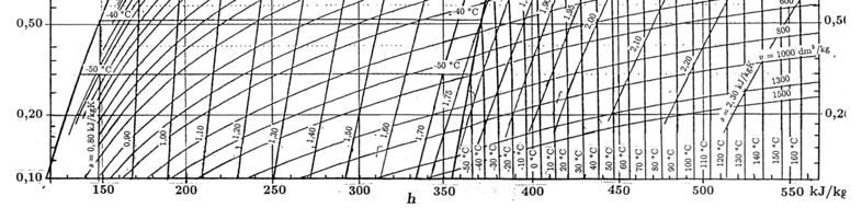
11 p,h diagram R-134a Picture: ÇB98 Åbo Akademi Univ - Thermal and Flow Engineering - Piispankatu 8, Turku /72 p,h diagram R-134a Picture:Ö96 Åbo Akademi Univ - Thermal and Flow Engineering - Piispankatu 8, Turku /72
")


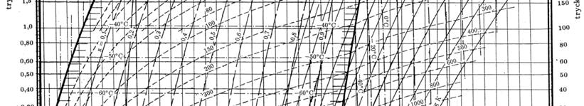
12 p,h diagram R-717 (NH 3 ) Picture:Ö96 Åbo Akademi Univ - Thermal and Flow Engineering - Piispankatu 8, Turku /72 p,h diagram R-22 Picture:Ö96 Åbo Akademi Univ - Thermal and Flow Engineering - Piispankatu 8, Turku /72


")

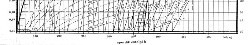
13 p,h diagram R-12 Picture:Ö96 Åbo Akademi Univ - Thermal and Flow Engineering - Piispankatu 8, Turku /72 p,h diagram R-744 (CO 2 ) Åbo Akademi Univ - Thermal and Flow Engineering - Piispankatu 8, Turku /72
14 p,h diagram R-407c ÅA VST heat pump Note sloping lines for boiling / condensation A zeotropic blend of difluoromethane (R-32), pentafluoroethane (R-125), and 1,1,1,2-tetrafluoroethane (R-134a) Åbo Akademi Univ - Thermal and Flow Engineering - Piispankatu 8, Turku /72 ÅA Refrigeration / Kylteknik 2.4 The real vapour-compression cycle Åbo Akademi Univ - Thermal and Flow Engineering - Piispankatu 8, Turku /72
15 Real vapour-compression cycle /1 In a real refrigerator quite a few irreversibilities reduce the efficiency: Fluid friction (gives heat ) Heat exhange with the surroundings Picture: ÇB98 The real process differs a bit from the ideal process: To ensure complete vaporisation, the refrigerant is slightly overheated at the evaporator inlet (8) A (long) line between evaporator and compressor gives fluid friction and heat exchange with surroundings (8 1) Åbo Akademi Univ - Thermal and Flow Engineering - Piispankatu 8, Turku /72 Real vapour-compression cycle /2 More differences compared to the ideal process: The compression is not isentropic: s > 0 (1 2) or s < 0 (1 2 ) by cooling, decreasing the volume! Picture: ÇB98 There will be some pressure drop between compressor and condensor, in the condensor, between condensor and throttling device (2/2 4 5) and in the evaporator The saturated liquid will be sub-cooled before going to the throttling device, located near the evaporator. Åbo Akademi Univ - Thermal and Flow Engineering - Piispankatu 8, Turku /72
16 Example: real vapour-compression cycle /1 A vapour-compression refrigeration cycle uses refrigerant R-134a with mass flow ṁ = 0.05 kg/s. Vapour enters the compressor at -10 C, 1.4 bar and leaves it at 50 C, 8 bar. The vapour enters the condenser at 7.2 bar and is cooled to 26 C. The throttling valve reduces the pressure to 1.5 bar. Calculate: The heat removal Q L and the compressor power W in The adiabatic (isentropic) efficiency of the compressor The COP R value Picture: ÇB98 Neglect the heat tranfer and pressure drops in connecting lines Åbo Akademi Univ - Thermal and Flow Engineering - Piispankatu 8, Turku /72 Example: real vapour-compression cycle /2 At p 1,T 1 : h 1 = kj/kg At p 2,T 2 : h 2 = kj/kg At p 3,T 3 : h 3 h f = kj/kg h 4 h 3 Picture: ÇB98 Q L = ṁ (h 1 -h 4 ) = 7.88 kw W in = ṁ (h 2 -h 1 ) = 2.05 kw Adiabatic eff. of compressor η c = (h 2s h 1 )/(h 2 -h 1 ) p 2s = 8 bar, s 2s = s 1, h 2s = kj/kg gives η c = Finally, COP R = Q L /W in = 7.88 kw / 2.05 kw = 3.84 Åbo Akademi Univ - Thermal and Flow Engineering - Piispankatu 8, Turku /72
 and gives it off at higher temperature (and pressure) at another location A refrigerant (sv: köldmedie, kylmedel)")
17 ÅA Refrigeration / Kylteknik 2.5 Refrigerants for vapour-compression refrigerators Åbo Akademi Univ - Thermal and Flow Engineering - Piispankatu 8, Turku /72 Refrigerants, freezing mixtures In a refrigeration process, energy is converted into transferred heat, using a heat carrier. The heat carrier medium will take up the heat at a low temperature (and pressure) and gives it off at higher temperature (and pressure) at another location A refrigerant (sv: köldmedie, kylmedel) participates in the process by a phase transition and/or pressure changes. It can also be electricity! A cooling or freezing mixture (sv: köldblandning) can carry or store heat, which can involve a phase transition, but little or no pressure changes. Coolant for an engine: not a refrigerant... Picture: Åbo Akademi Univ - Thermal and Flow Engineering - Piispankatu 8, Turku /72
 per unit volume Safe handling, non-toxic, no smell Low cost Chemically stable Should not be problematic when contacting water, oil, air when contacting")

 to +85 C (heat pumps) At the lowest temperature the refrigerant should have enough pressure to allow for 1) transport to the evaporator (and compressor), 2) proper operation of")
18 Refrigerants for vapourcompression (v-c) systems /1 T critical > T process, maximum and T melt < T process, minimum Reasonable pressure levels p sat at T boil and T condens Large Δh vaporisation/condensation ( latent heat ) per unit volume Safe handling, non-toxic, no smell Low cost Chemically stable Should not be problematic when contacting water, oil, air when contacting metals, rubber or other polymers at high temperatures (non-flammable!) for the environment: ozone layer depletion, the enhanced greenhouse effect Picture: Åbo Akademi Univ - Thermal and Flow Engineering - Piispankatu 8, Turku /72 Refrigerants for v-c systems /2 Most important: the temperature levels of the cold and hot spaces with which the refrigerant exchanges heat Temperatures at the condensor ranges from -20 C (cold winter air) to +85 C (heat pumps) At the lowest temperature the refrigerant should have enough pressure to allow for 1) transport to the evaporator (and compressor), 2) proper operation of the throttling device and 3) avoid air leakage into the system in practice a bit > 1 bar At the highest temperature the pressure should not be so high that expensive pressure vessels and tubing elements are needed in practice below 20 bar, preferably. Picture: Picture: Åbo Akademi Univ - Thermal and Flow Engineering - Piispankatu 8, Turku /72

 (R-6xx) (Non-)Azeotropic mixtures R-4xx and R-5xx, respectively Inorganics R-7yy, yy = molar mass (g/mol): NH 3 R-717, CO 2 R-744 making a return; used in aircraft Air also used in aircraft; and")
19 Refrigerants for v-c systems /3 R-codes Used / found in refrigeration systems (see also D03, TW00): CFCs (chloro fluoro carbons), HCFCs (hydro chloro fluoro carbons), HFCs (hydro fluoro carbons) mostly CFCs: R-11 in water chillers in building air conditioning, R-12 in domestic refrigerators, in automotive air conditioning, R-22 in air conditioning, in industrial refrigeration, R-134a replaces R-12, R-502 (R-115 / R-22 mix) in supermarket refrigeration Ammonia primarily in food refrigeration; other inorganics (R-7xx) Hydrocarbons (C 3, C 2, C 2=...) (R-6xx) (Non-)Azeotropic mixtures R-4xx and R-5xx, respectively Inorganics R-7yy, yy = molar mass (g/mol): NH 3 R-717, CO 2 R-744 making a return; used in aircraft Air also used in aircraft; and also: Water Not used any longer: ethyl ether, MeCl, SO 2 Halogenated hydrocarbon R-code: rightmost digit = no. of F, 10-digit = 1+no. of H, 100-digit = -1+no. of C, 1000-digit = no. of double bonds, a indicates isomer unbalance, the rest is Cl, B = no. of Br. Åbo Akademi Univ - Thermal and Flow Engineering - Piispankatu 8, Turku /72 Picture: Examples R- codes R-11 F=1, H+1 = 1, C-1 = 0, rest is Cl CFCl 3 R-134a: F = 4, H = 2, C = 2, a: assymmetric C 2 H 2 F 4 CF 3 -CFH 2 Åbo Akademi Univ - Thermal and Flow Engineering - Piispankatu 8, Turku
 2 O R-610 +35 CCl 3 F R-11 +24 SO 2 R-764-10 CCl 2 F 2 R-12-30 CH 3 Cl R-40-24 CHClF 2 R-22-41 CH")
20 Refrigerant vapour pressure Picture: S90 Vapour pressures of gases and refrigerants Åbo Akademi Univ - Thermal and Flow Engineering - Piispankatu 8, Turku /72 Some refrigerant data Gas Refrigerant T boil C * Gas Refrigerant T boil C * (C 2 H 5 ) 2 O R CCl 3 F R SO 2 R CCl 2 F 2 R CH 3 Cl R CHClF 2 R CH 2 Cl 2 R C 2 Cl 3 F 3 R NH 3 R C 2 Cl 2 F 4 R CO 2 R C 2 ClF 5 R CH 4 R CF 3 CH 2 F R-134a -26 C 2 H 6 R i-c 4 H 10 R-600a -12 CHClF 2 + C 2 ClF 5 ** hydrocarbon mix * for pressure = 1 bar ** azeotrope R HC-12a -33 Åbo Akademi Univ - Thermal and Flow Engineering - Piispankatu 8, Turku /72
 Picture: http://img.alibaba.")

21 Refrigerants for v-c systems /4 Boiling temperatures for 1 bar and 20 bar Ammonia: -33 C and +50 C R12: -30 C and +70 C R11: +25 C and +140 C R114: +5 C and +120 C R134a: -26 C and + 68 C Heat of vaporisation and density at 0 C: Ammonia: 1260 kj/kg, 3.45 kg/m kj/m 3 R22: 207 kj/kg, kg/m kj/m 3 (volumetric heat of vaporisation) Picture: Pure_Brand_New_R134a_Refrigerant_In_DOT_Or_Normal_Cylinders.jpg Åbo Akademi Univ - Thermal and Flow Engineering - Piispankatu 8, Turku /72 Greenhouse gases (GHGs) Greenhouse gases (GHGs), most importantly carbon dioxide (CO 2 ), methane (CH 4 ) and nitrous oxide (N 2 O) trap the outgoing solar radiation that is emitted by the earth s surface, which leads to global warming Note that water causes ⅔ of the greenhouse effect; the changing amounts of other GHGs cause an enhanced greenhouse effect Other GHGs and their global warming potential (GWP, CO 2 = 1 by definition) CH 4 (~22), N 2 O (~300) HFCs (hydro fluoro carbons) ( ) PFCs (per fluoro carbons) (7400) SF 6 (23900) Source: ZK01 Picture: Åbo Akademi Univ - Thermal and Flow Engineering - Piispankatu 8, Turku /72
 Class I ODS (Ozone Depleting Potential, ODP 0.1.")
 compounds: HFCs, PFCs, SF 6 Class II ODS (ODP << 1) HCFCs (hydrogenated chloro fluoro carbons) ODP = (definition) 1 for CFC-11 (R-11) Source: ZK01 Picture: http://www.geography.hunter.cuny.")

22 Ozone depleting substances (ODS) ODS substances do not have a direct global warming effect but influence the formation/ destruction of tropospheric/ stratospheric ozone Most important: CO, NOx, non-methane VOCs (volatile organic compounds) Class I ODS (Ozone Depleting Potential, ODP ) Carbon tetrachloride, methyl chloroform, halons C n F x Cl y Br z CFCs are replaced by non-ods (but GHG!) compounds: HFCs, PFCs, SF 6 Class II ODS (ODP << 1) HCFCs (hydrogenated chloro fluoro carbons) ODP = (definition) 1 for CFC-11 (R-11) Source: ZK01 Picture: wc.notes/1.atmosphere/ozone_depletion.2.htm Åbo Akademi Univ - Thermal and Flow Engineering - Piispankatu 8, Turku /72 Refigerant use in Finland Most important: CFCs R11, R12; HFC R134a (R-22 belongs to HCFC group) Finnish decision 1990: use of CFC forbidden except in special cases EU legislation: production and import/expert of CFCs forbidden as of 1995, as a well as putting CFC containing products on the market HCFC use (mainly R-22) is phased out Alternatives should be found for HFCs also (mainly R-134a and R- 400-types): Kigali agreement Oct e.g. CFCs, HCFCs and HFCs are hazardous wastes Special regulations as to the handling of CFCcontaining coolers, freezers, and isolation materials (R-11 in poly urethane foam!) In the future, more use of iso-butane (R-600a), propane, propene, CO 2 and ammonia End-of-life refrigerator handling at Ekokem Åbo Akademi Univ - Thermal and Flow Engineering - Piispankatu 8, Turku /72 Pictures: Sources: Ö96, D03, SKL06/12

23 Refrigerant properties LT = C; MT = C; HT = C Table: HTW08 Åbo Akademi Univ - Thermal and Flow Engineering - Piispankatu 8, Turku Refrigerant selection and COP (compared to R22; air conditioning with evaporator at T = 5 C) Picture: HTW08 Åbo Akademi Univ - Thermal and Flow Engineering - Piispankatu 8, Turku

24 ÅA Refrigeration / Kylteknik 2.6 Special vapour-compression refrigeration systems Åbo Akademi Univ - Thermal and Flow Engineering - Piispankatu 8, Turku /72 Cascade vapour-compression system In industry, efficiency may be more important than simplicity Sometimes the temperature range is too wide for a single v-c cycle use a cascade cycle (with several refrigerants) Two cycles, a bottoming cycle and a topping cycle are connected via a heat exchanger For the heat exchanger without heat losses or kinetic / m potential energy effects, and mass streams m A, m B : A (h h ) m B (h m h) m A B h h h h ; COPR Q W m Picture: ÇB98 m B (h h ) (h h ) m (h h ) Åbo Akademi Univ - Thermal and Flow Engineering - Piispankatu 8, Turku /72 L net,in One figure if the same refrigerant used in both cycles. A. B
 Mass stream m A = 0.05 kg/s. Calculate. mass stream m B, the heat stream Q L taken from the refrigerated space.")
25 Example: 2-stage vapour-compression system Consider the system in the Figure: a cascade v-c refrigerator operating between 1.4 and 8 bar with R-134a as refrigerant. The heat exchanger operates at 3.2 bar for both streams. (In practice p and T are a bit higher in the. bottom cycle.) Mass stream m A = 0.05 kg/s. Calculate. mass stream m B, the heat stream Q L taken from the refrigerated space. compressor power W in the COP R for the process Q L m B ( h 1 h m 4 A ) 7.13 kw; COP ( h R 5 h 8 Q W L ) m W B in m ( h 2 W h ) m in,top 3 W in,bottom h h m B ( h1 h4 ) ( h h ) m ( h m h h ( h h ) net, in A 6 5 B 2 1 B 5 2 A kg/s; h ) m 7.13 kw 1.60 kw ( h 4.46 Picture: ÇB98 h ) 1.60 kw Åbo Akademi Univ - Thermal and Flow Engineering - Piispankatu 8, Turku / m 6 A 5 B stage v-c refrigeration with sub-cooler Pictures: HTW08 Åbo Akademi Univ - Thermal and Flow Engineering - Piispankatu 8, Turku
26 2-stage compression refrigeration In a cascade system using one refrigerant, a mixing chamber (flash chamber) can be used instead of a heat exchanger Picture: ÇB98 Referred to as multistage compression refrigeration systems Saturated vapour from the flash chamber is fed to the high pressuire compressor, saturated liquid is fed to the low pressure expansion valve Åbo Akademi Univ - Thermal and Flow Engineering - Piispankatu 8, Turku /72 Example: 2-stage compression refrigeration /1 Consider the system in the Figure: a cascade c-v refrigerator operating between 1.4 and 8 bar with R-134a as refrigerant. The refrigerant leaves the condenser as saturated liquid and is throttled to a flash chamber at 3.2 bar. The vapour product is mixed with the refrigerant leaving the low pressure condenser. Assuming that both compressors are isentropic and that the refrigerant leaves the evaporator as saturated vapour: (continues) Picture: ÇB98 Åbo Akademi Univ - Thermal and Flow Engineering - Piispankatu 8, Turku /72
27 Example: 2-stage compression refrigeration /2 Calculate The mass fraction, x, ( quality ) of the refrigerant that is evaporated when throttled to the flash chamber The amount of heat that is removed from the refrigerated space and the compressor work per unit mass refrigerant flowing through the condenser, q L and w, and The COP R for the system; using the given T,s plot Picture: ÇB98 Åbo Akademi Univ - Thermal and Flow Engineering - Piispankatu 8, Turku /72 Example: 2-stage compression refrigeration /3 The mass fraction, x, of refrigerant evaporated as it is throttled to the flash chamber equals x 6 = (h 6 -h f )/ (h g -h f ) =(h 6 -h 7 )/(h 3 -h 7 ) = The amount of heat removed from the refrigerated space per unit mass equals q L = Q L / m = (1-x 6 ) (h 1 -h 8 ) = kj/kg Enthalpy h 9 follows from h 9 = x 6 h 3 +(1-x 6 ) h 2 = kj/kg With s 9 = kj/(kg K) = s 4 (at 8 bar) it follows from the data tables for R-134a that h 4 = kj/kg Compressor work w in = (1-x 6 ) (h 2 -h 1 )+(h 4 -h 9 ) = 31.8 kj/kg COPR = q L /w in = / 31.8 = 4.56 Picture: ÇB98 Åbo Akademi Univ - Thermal and Flow Engineering - Piispankatu 8, Turku /72

28 Multi-purpose refrigeration with a single compressor Picture: ÇB98 Refrigeration at more than one temperature (as in an ordinary household refrigerator + freezer) can be accomplished with one compressor by throttling in two steps Using one throttle valve and one cold temperature would give ice in the refrigerator section. Åbo Akademi Univ - Thermal and Flow Engineering - Piispankatu 8, Turku /72 Trans-critical CO 2 cycle Evaporation at -10 C, ~26 bar, gas cooling at C, at ~100 bar Picture: HTW08 Åbo Akademi Univ - Thermal and Flow Engineering - Piispankatu 8, Turku
29 ÅA Refrigeration / Kylteknik 2.7 Real vapour-compression cycles and p,h diagrams Åbo Akademi Univ - Thermal and Flow Engineering - Piispankatu 8, Turku /72 Real v-c refrigeration process A real vapourcompression refrigeration process in a p, h diagram: 1s = throttle valve in 2s = throttle valve out 2i = evaporator in 2u = evaporator out 2k = compressor in 1k = compressor out 1i = condenser in 1u = condenser out Includes pressure drop over connection lines 2u-2k and 1k-1i; heat exchange with surroundings and in the compressor Picture: Ö96 Åbo Akademi Univ - Thermal and Flow Engineering - Piispankatu 8, Turku /72
30 A commercial v-c refrigerator Picture: D03 Using a water-cooled condensor and a heat exchanger Temperature, pressure and heat of vaporisation can be optimised Åbo Akademi Univ - Thermal and Flow Engineering - Piispankatu 8, Turku /72 Vapour-compression refrigeration process with superheat / subcooling Picture: D03 Heat exchange between evaporator outlet and condensor outlet can improve the COP R value. Superheating by increased compressor pressure gives no improved efficiency but only results in larger condensor equipment Subcooling also ensures 100% liquid to the throttling valve and gives either more heat extracted from the refrigerated space, or a smaller required refrigerant mass flow Less attractive if the suction line to the compressor is long, especially when using ammonia as refrigerant Åbo Akademi Univ - Thermal and Flow Engineering - Piispankatu 8, Turku /72
31 Two-stage compression refrigeration Picture: Ö96 compressor Especially suitable for wide temperature ranges while still using one refrigerant at acceptable vapour pressures (a one-stage +10 C/-30 C unit can reach -65 C with two stages or -100 C with three) With minimum and maximum pressures p 1 and p 2 it can be shown that the optimum intermediate pressure level p m = (p 1 p 2 ) Disadvantages are lower efficiency, higher power input, increased temperature of refrigerant vapor from first compressor Åbo Akademi Univ - Thermal and Flow Engineering - Piispankatu 8, Turku /72 Cascade v-c systems /1 A two-stage cascade uses two different refrigerants and heat exchange Allows for a lower temperature than with a single-stage system Typically -150 C can be reached Compressor work decreases COP improves Condenser B of system I is cooled by evaporator C of system 2 Picture: D03 Åbo Akademi Univ - Thermal and Flow Engineering - Piispankatu 8, Turku /72

32 Cascade v-c systems /2 Cascade systems are commonly used for CO 2 or natural gas liquefaction Pictures: D03 Linde-Hampson system Intercooled compression Picture: ÇB98 Åbo Akademi Univ - Thermal and Flow Engineering - Piispankatu 8, Turku /72 ÅA Refrigeration / Kylteknik 2.8 Final remarks Åbo Akademi Univ - Thermal and Flow Engineering - Piispankatu 8, Turku /72

33 Defrosting, purging air Defrosting is necessary from time to time to remove ice (from air humidity) An effective method is to use hot refrigerant gas from compressor; otherwise warm air, water or electricity can be used Picture: D03 Air leaking into the system lowers the efficiency (usually being immiscible with the refrigerant it acts as an insulator at heat transfer surfaces, making the condensor smaller ) Manual or automatic purging methods can remove this air Åbo Akademi Univ - Thermal and Flow Engineering - Piispankatu 8, Turku /72 Tons of refrigeration For refrigerators used for producing ice, one way to express the capacity is as tons of refrigeration 1 ton of refrigeration = heat needed to freeze 1 short ton (= 2000 lbm = 907kg) water at 0 C to ice at 0 C in 24 hours 1 ton of refrigeration = 211 kj/min = 200 BTU/min = 3.52 kw heat removal from the refrigerated space See also A11 p. 99 Picture: Åbo Akademi Univ - Thermal and Flow Engineering - Piispankatu 8, Turku /72
34 Heat exchanger irreversibilities (vs91) A simple steady-state heat transfer process; heat is transported from medium 1 to medium 2 by conduction through a material that separates them. Temperature T 1 > T 2 Thermodynamic analysis Energy balance Q Q Entropy balance Q Q S gen T T S gen Q T Q T T T T T. Q 1. Q 2 T = T 1 T = T 2 This shows that S gen is large for large temperature differences (T 1 -T 2 ) and low temperatures T 1 and T 2. Åbo Akademi Univ - Thermal and Flow Engineering - Piispankatu 8, Turku /72 ÅA Refrigeration / Kylteknik 2.9 Vapour-compression cycle heat pumps Åbo Akademi Univ - Thermal and Flow Engineering - Piispankatu 8, Turku /72
 NOTE: COP HP = COP R +1")
 Total capacity (2013/2014): 600 000 HPs using 4 TWh year around buildings GSHP =")
35 Heat pumps using v-c cycle A heat pump vapour-compression system with reversing valve for summer / cooling (a) or winter / heating operation (b) NOTE: COP HP = COP R +1 Pictures: KJ05 Åbo Akademi Univ - Thermal and Flow Engineering - Piispankatu 8, Turku /72 Heat pumps in Finland (2013/2014) Total capacity (2013/2014): HPs using 4 TWh year around buildings GSHP = ground-source HP Source / picture: (accessed: ) Åbo Akademi Univ - Thermal and Flow Engineering - Piispankatu 8, Turku /72
 CB98: Y.A. Çengel, M.A. Boles Thermodynamics.")
 KJ05: D. Kaminski, M. Jensen Introduction to Thermal and Fluids Engineering, Wiley (2005) SEHB06: P.S. Schmidt, O. Ezekoye, J. R Howell, D.")
 TW00: A.R. Trott, T.C. Welsh Refrigeration and Air-Conditioning 3rd Ed. Butterworths-Heineman (2000) ZK01: R.")
36 Heat pumps in Finland ( ) Heat pumps: to be continued Total capacity (2015): ~ HPs using ~ 5 TWh year around buildings Source / picture: (accessed: ) Åbo Akademi Univ - Thermal and Flow Engineering - Piispankatu 8, Turku /72 Sources #2 A11: R. C. Arora Refrigeration and air conditioning, 2nd. Ed. PHI Learning Private Limited, New Delhi (2011) CB98: Y.A. Çengel, M.A. Boles Thermodynamics. An Engineering Approach, McGraw-Hill (1998) D03: İ. Dinçer Refrigeration systems and applications Wiley (2003) HTW08: G.F. Hundy, A.R. Trott, T.C. Welsh Refrigeration and air conditioning 4 th ed. Butterworth-Heinemann (2008) KJ05: D. Kaminski, M. Jensen Introduction to Thermal and Fluids Engineering, Wiley (2005) SEHB06: P.S. Schmidt, O. Ezekoye, J. R Howell, D. Baker Thermodynamics: An Integrated Learning System (Text + Web) Wiley (2006) S90: A.L. Stolk Koudetechniek A1, Delft University of Technology (1990) SKL06/12: Suomen Kylmäliikkeiden Liitto (2006, 2012) T06: S.R. Turns Thermal Fluid Sciences, Cambridge Univ. Press (2006) TW00: A.R. Trott, T.C. Welsh Refrigeration and Air-Conditioning 3rd Ed. Butterworths-Heineman (2000) ZK01: R. Zevenhoven, P. Kilpinen Control of pollutants in flue gases and fuel gases Picaset (Espoo), 2001 (Chapter 9) Ö96: G. Öhman Kylteknik, Åbo Akademi University (1996) See also: Martinez, I. Lectures on Thermodynamics lecture 18 (English or Spanish) updated and based on Termodinámica básica y aplicada", Ed. Dossat, Madrid (1992) ISBN Åbo Akademi Univ - Thermal and Flow Engineering - Piispankatu 8, Turku /72 Picture:
4.1 Refrigeration process comparison
 Refrigeration (Kylteknik) course # 424519.0 v. 2017 4. Refrigeration process comparison; process equipment Ron Zevenhoven Åbo Akademi University Thermal and Flow Engineering Laboratory / Värme- och strömningsteknik
Thermodynamics II Chapter 5 Refrigeration
 Thermodynamics II Chapter 5 Refrigeration Mohsin Mohd Sies Fakulti Kejuruteraan Mekanikal, Universiti Teknologi Malaysia Objectives Introduce the concepts of refrigerators and heat pumps and the measure
Refrigeration Cycles MOHAMMAD FAISAL HAIDER. Bangladesh University of Engineering and Technology
 Refrigeration Cycles MOHAMMAD FAISAL HAIDER LECTURER Department of Mechanical Engineering Department of Mechanical Engineering Bangladesh University of Engineering and Technology Objectives Introduce the
Chapter 11 REFRIGERATION CYCLES
 Thermodynamics: An Engineering Approach, 6 th Edition Yunus A. Cengel, Michael A. Boles McGraw-Hill, 2008 Chapter 11 REFRIGERATION CYCLES Wan Rosli Wan Sulaiman Copyright The McGraw-Hill Companies, Inc.
Refrigeration (Kylteknik) 8. Heat pumps, heat pipes, cold thermal energy storage
 8. Heat pumps, heat pipes, cold thermal energy storage") Refrigeration (Kylteknik) course # 424519.0 v. 2018 8. Heat pumps, heat pipes, cold thermal energy storage Ron Zevenhoven Åbo Akademi University Thermal and Flow Engineering Laboratory / Värme- och strömningsteknik
Refrigeration (Kylteknik) course # 424519.0 v. 2018 8. Heat pumps, heat pipes, cold thermal energy storage Ron Zevenhoven Åbo Akademi University Thermal and Flow Engineering Laboratory / Värme- och strömningsteknik
Chapter 11 REFRIGERATION CYCLES
 Thermodynamics: An Engineering Approach Seventh Edition in SI Units Yunus A. Cengel, Michael A. Boles McGraw-Hill, 2011 Chapter 11 REFRIGERATION CYCLES Mehmet Kanoglu University of Gaziantep Copyright
we will examine only the vapour compression systems transfers to the Carnot cycle can serve as the initial model of the ideal refrigeration cycle.
 Refrigeration Cycle Reading Problems 10-1 10-5, 10-7, 10-9 10-11, 10-14, 10-39 Definitions a refrigeration system removes thermal energy from a low-temperature region and transfers heat to a high-temperature
Chapter 10. Refrigeration and Heat Pump Systems
 Chapter 10 Refrigeration and Heat Pump Systems Learning Outcomes Demonstrate understanding of basic vaporcompression refrigeration and heat pump systems. Develop and analyze thermodynamic models of vapor-compression
Chapter 11 REFRIGERATION CYCLES. Department of Mechanical Engineering
 Chapter 11 REFRIGERATION CYCLES Dr Ali Jawarneh Department of Mechanical Engineering Hashemite University it Objectives Introduce the concepts of refrigerators and heat pumps and the measure of their performance.
Chapter 9. Refrigeration and Liquefaction
 Chapter 9 Refrigeration and Liquefaction Refrigeration is best known for its use in the air conditioning of buildings and in the treatment, transportation, and preservation of foods and beverages. It also
Thermodynamics I. Refrigeration and Heat Pump Cycles
 Thermodynamics I Refrigeration and Heat Pump Cycles Dr.-Eng. Zayed Al-Hamamre 1 Content Introduction The Reversed Carnot Cycle The Ideal Compression Refrigeration Systems Deviation from the ICRS Selection
Week 9. Refrigeration Cycles I. GENESYS Laboratory
 Week 9. Refrigeration Cycles I Objectives 1. Introduce the concepts of refrigerators and heat pumps and the measure of their performance. 2. Analyze the ideal vapor-compression refrigeration cycle. 3.
Last exam / sista tent
 Värme- och strömningsteknik Thermal and flow engineering Refrigeration Kylteknik Ron Zevenhoven Exam 24-2-2017 4 questions, max. points = 8 + 8 + 6 + 8 = 30 All support material is allowed except for telecommunication
Main Anthropogenic Sources of Greenhouse Gases Refrigerants
 Main Anthropogenic Sources of Greenhouse Gases Refrigerants Content Refrigerant definition Refrigerants Refrigerants as a source of GHG Refrigerant Definition A refrigerant is a substance or mixture, usually
Chapter 11. Refrigeration Cycles. Study Guide in PowerPoint
 Chapter 11 Refrigeration Cycles Study Guide in PowerPoint to accompany Thermodynamics: An Engineering Approach, 7th edition by Yunus A. Çengel and Michael A. Boles The vapor compression refrigeration cycle
CH2351 Chemical Engineering Thermodynamics II Unit V Refrigeration. Dr. M. Subramanian
 CH2351 Chemical Engineering Thermodynamics II Unit V www.msubbu.in Refrigeration www.msubbu.in Dr. M. Subramanian Associate Professor Department of Chemical Engineering Sri Sivasubramaniya Nadar College
RAC. Unit 1. Previous year Questions
 RAC Unit 1 Previous year Questions 1.What is the basic difference between open and closed Air refrigeration cycles? Describe a Bellcoleman or Reversed Joule air refrigeration cycle with the help of a neat
Due to its low temperature glide about 1.5 approx. (75% less than R-407C and R-427A), it is suitable for a wide range of applications.
, it is suitable for a wide range of applications.") TECHNICAL DATA SHEET R434A () Features and uses of R-434A () is a non-flammable HFC mixture. ODP = 0, compatible with traditional mineral lubricants, alkyl benzene and also with synthetic POE, so there
TECHNICAL DATA SHEET R434A () Features and uses of R-434A () is a non-flammable HFC mixture. ODP = 0, compatible with traditional mineral lubricants, alkyl benzene and also with synthetic POE, so there
Chapter 2. Alternatives to HCFCs and their Characteristics
 Alternatives to HCFCs and their Characteristics Refrigerant - General Chemical used in a cooling system, such as an air conditioner or refrigerator, as the heat carrier which changes from vapour to liquid
Compendium DES July 2016, CARN
 Compendium DES July 2016, CARN 1 Contents Contents... 2 1. Energy balance... 4 Using Energy Balance for analyzing energy systems... 4 Energy Balance definition... 4 Steady state, steady flow... 4 Methodology...
(Refer Slide Time: 00:00:40 min)
") Refrigeration and Air Conditioning Prof. M. Ramgopal Department of Mechanical Engineering Indian Institute of Technology, Kharagpur Lecture No. # 10 Vapour Compression Refrigeration Systems (Refer Slide
Refrigeration and Air Conditioning Prof. M. Ramgopal Department of Mechanical Engineering Indian Institute of Technology, Kharagpur Lecture No. # 10 Vapour Compression Refrigeration Systems (Refer Slide
Homework Chapter2. Homework Chapter3
 Homework Chapter2 2/1 A storage tank holds methane at 120 K, with a quality of 25 %, and it warms up by 5 C per hour due to a failure in the refrigeration system. How long time will it take before the
Engineering Thermodynamics. Chapter 7
 Chapter 7 Vapor-Power Cycle 4.1 Introduction Steam power plants are the major sources of power generation. They operate essentially on the principle that steam generated in the boiler passes through steam
Paper No. : 04 Paper Title : Unit Operations in Food processing Module 11 : Principles of Refrigeration
 Paper No. : 04 Paper Title : Unit Operations in Food processing Module 11 : Principles of Refrigeration 11.1 Introduction Preservation of foods is a vital processing step in food processing. There are
WORK STUDY ON LOW TEMPERATURE (CASCADE) REFRIGERATION SYSTEM
 REFRIGERATION SYSTEM") WORK STUDY ON LOW TEMPERATURE (CASCADE) REFRIGERATION SYSTEM Sachin Kumar 1, Vicky Ranga 2 1Assistant Professor, Department of Mechanical Engineering, Jagan Nath University Jhajjar, Haryana, India. 2Scholar.
WORK STUDY ON LOW TEMPERATURE (CASCADE) REFRIGERATION SYSTEM Sachin Kumar 1, Vicky Ranga 2 1Assistant Professor, Department of Mechanical Engineering, Jagan Nath University Jhajjar, Haryana, India. 2Scholar.
RS-70 is suitable as a direct replacement for R-22 in low, medium and high temperatures in a great number of applications:
 TECHNICAL DATA SHEET Features and uses of is a non-azeotropic blend of HFC with zero Ozone Depletion Potential et low Global Warming Potential (GWP), formulated to meet the requirements of the F-Gas Regulation
Refrigeration Systems
 Refrigeration Systems COP COP = coefficient of performance Air conditioners, refrigerators: COP=QL/Wnet Heat pumps: COP=QH/Wnet Energy balance: Wnet+QL=QH From Cengel, Thermodynamics: An Engineering Approach,
REFRIGERATION CYCLE Principles of Mechanical Refrigeration Level 2: Cycle Analysis
 REFRIGERATION CYCLE Principles of Mechanical Refrigeration Level 2: Cycle Analysis Technical Development Program Technical Development Programs (TDP) are modules of technical training on HVAC theory, system
Energy Use in Refrigeration Systems
 2012 Rocky Mountain ASHRAE Technical Conference Energy Use in Refrigeration Systems PRESENTED BY: Scott Martin, PE, LEED AP BD+C Objectives Understand mechanical refrigeration terms Describe how heat is
A Comparison Between Refrigerants Used In Air Conditioning
 A Comparison Between Refrigerants Used In Air Conditioning Derya Özkan, Özden Agra and Özlem Çetin University of Yildiz Technical University, Turkey Corresponding email: tumer@yildiz.edu.tr SUMMARY It
Chapter 10 Lyes KADEM [Thermodynamics II] 2007
![Chapter 10 Lyes KADEM [Thermodynamics II] 2007](/thumbs/85/92279486.jpg "Chapter 10 Lyes KADEM [Thermodynamics II] 2007") Refrigeration Cycles The objective of refrigeration cycles is to transfer the heat from a low temperature region to a high temperature region. - if the objective of the cycle is to decrease the lowest
Refrigeration Cycles The objective of refrigeration cycles is to transfer the heat from a low temperature region to a high temperature region. - if the objective of the cycle is to decrease the lowest
Subscripts 1-4 States of the given system Comp Compressor Cond Condenser E Evaporator vol Volumetric G Gas L Liquid
 Simulation Analysis of Compression Refrigeration Cycle with Different Refrigerants P.Thangavel, Dr.P.Somasundaram, T.Sivakumar, C.Selva Kumar, G.Vetriselvan Abstract --- In this analysis, the performance
Refrigerator and Heat Pump Objectives
 10 CHAPTER Refrigeration Cycles 10-1 Refrigerator and Heat Pump Objectives The objective of a refrigerator is to remove heat (Q L ) from the cold medium; the objective of a heat pump is to supply heat
s. Properties for R134a are as follows : Saturated R-134a Superheated R-134a
 CHAPTER 9 REFRIGERATION & AIR-CONDITIONING YEAR 2012 ONE MARK Common Data For Q. 1 and Q.2 A refrigerator operates between 120 kpa and 800 kpa in an ideal vapour compression cycle with R-134a as the refrigerant.
Evaluation of Vapour Compression Refrigeration System Using Different Refrigerants
 Evaluation of Vapour Compression Refrigeration System Using Different Refrigerants Mukesh K. Agrawal, Dr. Ashok G. Matani Abstract- The performance of heat transfer is one of the most important research
Performance Assessment of Water Cooled Condenser Refrigeration System
 Energy and Power 2017, 7(3): 70-74 DOI: 10.5923/j.ep.20170703.03 Performance Assessment of Water Cooled Condenser Refrigeration System Sheetal Narayan Shetty *, Prashanth Kamath Department of Mechanical
HVAC Fundamentals & Refrigeration Cycle
 HVAC Fundamentals & Refrigeration Cycle Change of State of Water & the Refrigeration Cycle Change of State Water The Basic Refrigeration Cycle Types of DX Systems The Chilled water System The Cooling Tower
11/22/2014. (c) DR.A.M.SURENDRA KUMAR
 DR.A.M.SURENDRA KUMAR") 11/22/2014 (c) DR.A.M.SURENDRA KUMAR 1 HISTORY A substance capable of absorbing heat from another required substance(space) can be used as Refrigerant. Air was used as refrigerant in olden days in many
11/22/2014 (c) DR.A.M.SURENDRA KUMAR 1 HISTORY A substance capable of absorbing heat from another required substance(space) can be used as Refrigerant. Air was used as refrigerant in olden days in many
Thermodynamic study of R134a in Vapour Compression Refrigeration System in Summer Climate
 International Journal of Research in Engineering and Innovation (IJREI) Vol-1, Issue-2, (2017), 49-53 International Journal of Research in Engineering and Innovation (IJREI) journal home page: http://www.ijrei.com
Refrigerants Type Expensive Coefficient of Performance Toxic
 Chapter 11: Refrigeration Cycles 11.5. Selecting the Right Refrigerants When designing a refrigeration system, there are several refrigerants from which to choose, such as chlorofluorocarbons (CFCs), ammonia,
Chapter 8. Production of Power from Heat
 Chapter 8 Production of Power from Heat 8.1 THE STEAM POWER PLANT The Carnot-engine cycle, described in Sec. 5.2, operates reversibly and consists of two isothermal steps connected by two adiabatic steps.
Refrigeration and Air Conditioning
 Refrigeration and Air Conditioning 1. Pick up the wrong statement. A refrigerant should have (a) Tow specific heat of liquid (b) high boiling point (c) high latent heat of vaporisation (d) higher critical
Role of Nano-technology for improving of thermal performances of vapour compression refrigeration system (VCRS): An Overview
: An Overview") International Journal of Research in Engineering and Innovation Vol-2, Issue-1 (2018), 21-28 International Journal of Research in Engineering and Innovation (IJREI) journal home page: http://www.ijrei.com
International Journal of Research in Engineering and Innovation Vol-2, Issue-1 (2018), 21-28 International Journal of Research in Engineering and Innovation (IJREI) journal home page: http://www.ijrei.com
REFRIGERATION AND AIR CONDITIONING
 REFRIGERATION AND AIR CONDITIONING SECOND EDITION S.N. Sapali Professor of Mechanical Engineering College of Engineering, Pune Delhi-110092 2014 REFRIGERATION AND AIR CONDITIONING, Second Edition S.N.
Thermodynamic Calculations of Two-Stage Vapor Compression Refrigeration Cycle with Flash Chamber and Separate Vapor Mixing Intercooler
 Thermodynamic Calculations of Two-Stage Vapor Compression Refrigeration Cycle with Flash Chamber and Separate Vapor Mixing Intercooler Author: Volodymyr Voloshchuk Vl.volodya@gmail.com Introduction In
SIDDHARTH GROUP OF INSTITUTIONS :: PUTTUR Siddharth Nagar, Narayanavanam Road AUTONOMOUS QUESTION BANK (DESCRIPTIVE) UNIT I
 UNIT I") SIDDHARTH GROUP OF INSTITUTIONS :: PUTTUR Siddharth Nagar, Narayanavanam Road 517583 AUTONOMOUS QUESTION BANK (DESCRIPTIVE) Subject with Code : Refrigeration and Air Conditioning (16ME8806) Course & Branch:
SIDDHARTH GROUP OF INSTITUTIONS :: PUTTUR Siddharth Nagar, Narayanavanam Road 517583 AUTONOMOUS QUESTION BANK (DESCRIPTIVE) Subject with Code : Refrigeration and Air Conditioning (16ME8806) Course & Branch:
Purpose of Refrigeration
 Refrigeration Outline Purpose of refrigeration Examples and applications Choice of coolant and refrigerants Phase diagram of water and CO 2 Vapor compression refrigeration system Pressure-enthalpy diagram
EVALUATION OF REFRIGERANT R290 AS A REPLACEMENT TO R22
 EVALUATION OF REFRIGERANT R290 AS A REPLACEMENT TO R22 Ameya P. Shrivastava 1, Choudhari Chandrakishor S. 2 1,2 Mechanical Department, AISSMS College of Engineering, Pune 411001, (India) ABSTRACT HCFC
η second law = Second law efficiency
 EXERGY ANALYSIS OF VAPOUR COMPRESSION REFRIGERATION CYCLE BASED AUTOMOTIVE AIR CONDITIONER USING ECO FRIENDLY REFRIGERANTS Vijender Singh Saini 1, Balvinder 2, Pardeep Kumar 3 1 M.Tech Scholar, 2,3 Assistant
Refrigeration Cycles. Refrigerators, Air-conditioners & Heat Pumps. Refrigeration Capacity/Performance. Dr. Md. Zahurul Haq
 Refrigeration Cycles Dr. Md. Zahurul Haq Professor Department of Mechanical Engineering Bangladesh University of Engineering & Technology (BUET) Dhaka-1000, Bangladesh zahurul@me.buet.ac.bd http://teacher.buet.ac.bd/zahurul/
PRESSURE-ENTHALPY CHARTS AND THEIR USE By: Dr. Ralph C. Downing E.I. du Pont de Nemours & Co., Inc. Freon Products Division
 INTRODUCTION PRESSURE-ENTHALPY CHARTS AND THEIR USE The refrigerant in a refrigeration system, regardless of type, is present in two different states. It is present as liquid and as vapor (or gas). During
T270 COP R = Q L. c Dr. Md. Zahurul Haq (BUET) Refrigeration Cycles ME 6101 (2017) 2 / 23 T354
 Refrigeration Cycles ME 6101 (2017) 2 / 23 T354") Refrigerators, Air-conditioners & Heat Pumps Refrigeration Cycles Dr. Md. Zahurul Haq Professor Department of Mechanical Engineering Bangladesh University of Engineering & Technology (BUET) Dhaka-1000,
Refrigerators, Air-conditioners & Heat Pumps Refrigeration Cycles Dr. Md. Zahurul Haq Professor Department of Mechanical Engineering Bangladesh University of Engineering & Technology (BUET) Dhaka-1000,
STUDY OF WATER AS A REFRIGERANT AND COMPARE IT WITH OTHER CURRENT WORKING REFRIGERANTS
 STUDY OF WATER AS A REFRIGERANT AND COMPARE IT WITH OTHER CURRENT WORKING REFRIGERANTS Abstract Water - natural, non-toxic, low cost, environmentally friendly, and widely available, is widely used in water
CHAPTER 1 INTRODUCTION
 CHAPTER 1 INTRODUCTION 1.1 CFC REFRIGERANTS Since the 1930s, chlorofluorocarbons (CFCs) have been widely used as foam blowing agents, aerosols and especially refrigerants due to their pre-eminent properties
Thermodynamics: Homework A Set 7 Jennifer West (2004)
") Thermodynamics: Homework A Set 7 Jennifer West (2004) Problem 1 Water is the working fluid in a Carnot vapor power cycle. Saturated liquid enters the boiler at a pressure of 18 MPa, and saturated vapor
Thermodynamics: Homework A Set 7 Jennifer West (2004) Problem 1 Water is the working fluid in a Carnot vapor power cycle. Saturated liquid enters the boiler at a pressure of 18 MPa, and saturated vapor
International Journal of Research in Engineering and Innovation Vol-2, Issue-2 (2018),
,") International Journal of Research in Engineering and Innovation Vol-2, Issue-2 (2018), 183-190 International Journal of Research in Engineering and Innovation (IJREI) journal home page: http://www.ijrei.com
International Journal of Research in Engineering and Innovation Vol-2, Issue-2 (2018), 183-190 International Journal of Research in Engineering and Innovation (IJREI) journal home page: http://www.ijrei.com
Experimentation and Fabrication of Iceplant Using Ecofriendly Refrigerant
 Experimentation and Fabrication of Iceplant Using Ecofriendly Refrigerant Shubham Rangari 1, Shubham Mahakalkar 2, Shubham Tiple 3, Praharsh Marathe 4, Sameer Bansod 5, Sunnyraj Katam 6, Suraj Nagrare
Performance Evaluation of Eco- Friendly Alternate Refrigerants for VCRS
 Performance Evaluation of Eco- Friendly Alternate Refrigerants for VCRS Lalit Narayan, Abhishek Arya 2,2 M. Tech. Scholar, Associate Professor,,2 Scope College of Engineering, Bhopal, India Abstract: The
Chapter 10 VAPOR AND COMBINED POWER CYCLES
 Thermodynamics: An Engineering Approach Seventh Edition Yunus A. Cengel, Michael A. Boles McGraw-Hill, 2011 Chapter 10 VAPOR AND COMBINED POWER CYCLES Copyright The McGraw-Hill Companies, Inc. Permission
Recommendations to retrofit positive existing installations running with HFCs (R404A & R507) RETROFIT POSITIVE & MEDIUM REFRIGERATING SYSTEMS
 RETROFIT POSITIVE & MEDIUM REFRIGERATING SYSTEMS") COMMERCIAL REFRIGERATION RETROFIT POSITIVE & MEDIUM REFRIGERATING SYSTEMS www.tecumseh.com Recommendations to retrofit positive existing installations running with HFCs (R404A & R507) 1-HCFCs & HFCs Retrofit
COMMERCIAL REFRIGERATION RETROFIT POSITIVE & MEDIUM REFRIGERATING SYSTEMS www.tecumseh.com Recommendations to retrofit positive existing installations running with HFCs (R404A & R507) 1-HCFCs & HFCs Retrofit
Natural gas liquefaction cycles
 Natural gas liquefaction cycles Constantinos Hadjistassou, PhD Assistant Professor Programme in Oil & Gas (Energy) Engineering University of Nicosia Web: www.carbonlab.eu Nov., 2015 Overview Liquefaction
HFCs or the Old Refrigerants - what is the best Choice?
 HFCs or the Old Refrigerants - what is the best Choice? Hermann Halozan Institute of Thermal Engineering, Graz University of Technology Inffeldgasse 25 / B, A-8010 Graz, Austria, Phone: +43 316 873-7303
International Research Journal of Engineering and Technology (IRJET) e-issn: Volume: 04 Issue: 05 May p-issn:
 e-issn: Volume: 04 Issue: 05 May p-issn:") Comparison of Second Law Efficiency and Exergy Analysis of Refrigerants R-12, R-22, R-407C Influenced by Evaporator Temperature for Vapour Compression Refrigeration System Md Ozair Arshad Guest Faculty,
Comparison of Second Law Efficiency and Exergy Analysis of Refrigerants R-12, R-22, R-407C Influenced by Evaporator Temperature for Vapour Compression Refrigeration System Md Ozair Arshad Guest Faculty,
(ME-225) HEATING, VENTILATION AND AIR-CONDITIONING SYSTEM
 HEATING, VENTILATION AND AIR-CONDITIONING SYSTEM") (ME-225) HEATING, VENTILATION AND AIR-CONDITIONING SYSTEM MUHAMMAD UMER SOHAIL PhD, AEROSPACE SCHOLOR (INSTITUTE OF SPACE TECHNOLOGY) MS POWER MECHANICAL (MUST) MBA (COL) EXECUTIVE (SAARC AIOU) BSC MECHANICAL
(ME-225) HEATING, VENTILATION AND AIR-CONDITIONING SYSTEM MUHAMMAD UMER SOHAIL PhD, AEROSPACE SCHOLOR (INSTITUTE OF SPACE TECHNOLOGY) MS POWER MECHANICAL (MUST) MBA (COL) EXECUTIVE (SAARC AIOU) BSC MECHANICAL
NATURAL REFRIGERANTS FOR HEAT PUMPS AND AIR-CONDITIONING SYSTEMS. Bernard Thonon Greth
 NATURAL REFRIGERANTS FOR HEAT PUMPS AND AIR-CONDITIONING SYSTEMS Bernard Thonon Greth bernard.thonon@greth.fr Artificial or Natural Refrigerants? Performances COP Capacity Cost Safety Pressure, Temperature
Performance and exergy analysis of vapour compression refrigeration system using various alternative of R134a.
 Performance and exergy analysis of vapour compression refrigeration system using various alternative of R134a. Raja Kumar Gond 1, Ravindra Pratap Chaudhary 2, Mohammad Amir Khan 3, Gaurav Jain 4 1Student,
ECO-FRIENDLY REFRIGERANTS. Dr Alka Bani Agrawal Professor,Mechanical Engg UIT,RGPV
 ECO-FRIENDLY REFRIGERANTS Dr Alka Bani Agrawal Professor,Mechanical Engg UIT,RGPV HISTORY OF REFRIGERATION Refrigeration relates to the cooling of air or liquids, thus providing lower temperature to preserve
International Journal of Research in Engineering and Innovation Vol-1, Issue-5 (2017), 68-72
, 68-72") International Journal of Research in Engineering and Innovation Vol-1, Issue-5 (2017), 68-72 International Journal of Research in Engineering and Innovation (IJREI) journal home page: http://www.ijrei.com
International Journal of Research in Engineering and Innovation Vol-1, Issue-5 (2017), 68-72 International Journal of Research in Engineering and Innovation (IJREI) journal home page: http://www.ijrei.com
Design & Fabrication of Hybrid Cooler
 IJIRST International Journal for Innovative Research in Science & Technology Volume 2 Issue 11 April 2016 ISSN (online): 2349-6010 Design & Fabrication of Hybrid Cooler Shashank Chauragade Mukul Kshirsagar
Fig.: macroscopic kinetic energy is an organized form of energy and is much more useful
 Harnessing Energy Fig.: macroscopic kinetic energy is an organized form of energy and is much more useful Vapor Power Cycle The vast majority of electrical generating plants are variations of vapor power
S.A. Klein and G.F. Nellis Cambridge University Press, 2011 = 90 F. compressor. condenser. 5 evaporator 1. evap
 9.A-1 Dedicated subcooling is a novel modification for frozen food refrigeration in supermarkets. With the dedicated subcooling modification, liquid refrigerant leaving the condenser is further cooled
S.A. Klein and G.F. Nellis Cambridge University Press, 2011
 12.A-1 A mixture of helium and water vapor is flowing through a pipe at T= 90 C and P = 150 kpa. The mole fraction of helium is y He = 0.80. a.) What is the relative humidity of the mixture? b.) What is
The Problem of Counterfeit Refrigerants
 The Problem of Counterfeit Refrigerants James K Carson President, Commission C2, International Institute of Refrigeration Senior Lecturer, School of Engineering, University of Waikato j.carson@waikato.ac.nz
UEE11 Electrotechnology. Training Package. UEENEEJ108A Recover, pressure test, evacuate, charge and leak test refrigerants SAMPLE.
 UEE11 Electrotechnology Training Package UEENEEJ108A Recover, pressure test, evacuate, charge and leak test refrigerants Learner Workbook Version 1 Training and Education Support Industry Skills Unit Meadowbank
ASSESSMENT OF R430A REFRIGERANT AS A POSSIBLE SUBSTITUTE TO R134A REFRIGERANT IN LARGE CAPACITY FREEZER
 University of Maiduguri Faculty of Engineering Seminar Series Volume 6, december 5 ASSESSMENT OF REFRIGERANT AS A POSSIBLE SUBSTITUTE TO R34A REFRIGERANT IN LARGE CAPACITY FREEZER S. Shodiya*, M.B. Oumarou
ISSN Vol.08,Issue.21, November-2016, Pages:
 ISSN 2348 2370 Vol.08,Issue.21, November-2016, Pages:4164-4170 www.ijatir.org Thermal Analysis of Vapour Compression Cycle for Different Refrigerants ALI MOHAMMED ABDOULHA MASSOUD 1, DR. MOHAMMAD TARIQ
A Theoretical investigation on HC Mixtures as Possible Alternatives to R134a in Vapor Compression Refrigeration
 ANALELE UNIVERSITĂłII EFTIMIE MURGU REŞIłA ANUL XXI, NR. 1, 2014, ISSN 1453-7397 Feiza Memet A Theoretical investigation on HC Mixtures as Possible Alternatives to R134a in Vapor Compression Refrigeration
Commercial CO 2 Refrigeration Systems
 Commercial CO 2 Refrigeration Systems Guide for Subcritical and Transcritical CO 2 Applications 2 Contents Chapter 1. Introduction 4 Chapter 2. CO 2 Basics and Considerations as a Refrigerant 5 Section
SAMPLE STUDY MATERIAL
 R.A.C.-ME GAE, IES, PSU SAMPLE SUDY MAERIAL Mechanical Engineering ME Postal Correspondence Course Refrigeration & Air Conditioning GAE, IES & PSUs R.A.C.-ME GAE, IES, PSU 2 C O N E N. INRODUCION & BASIC
c Dr. Md. Zahurul Haq (BUET) Refrigeration Cycles ME 6101 (2013) 2 / 25 T270 COP R = Q L
 Refrigeration Cycles ME 6101 (2013) 2 / 25 T270 COP R = Q L") Refrigeration Cycles Dr. Md. Zahurul Haq Professor Department of Mechanical Engineering Bangladesh University of Engineering & Technology (BUET) Dhaka-1000, Bangladesh zahurul@me.buet.ac.bd http://teacher.buet.ac.bd/zahurul/
Refrigeration Cycles Dr. Md. Zahurul Haq Professor Department of Mechanical Engineering Bangladesh University of Engineering & Technology (BUET) Dhaka-1000, Bangladesh zahurul@me.buet.ac.bd http://teacher.buet.ac.bd/zahurul/
CHAPTER 1 INTRODUCTION
 1 CHAPTER 1 INTRODUCTION 1.1 Background The science which deals with creating a controlled climate in indoor space is called air conditioning. Earlier days the air-conditioning was treated as a luxury,
Q. Which hydrocarbons can be used as a refrigerant? The following hydrocarbons can be used as a refrigerant in cooling & heating applications:
 Basic Facts About Hydrocarbons Q. What are hydrocarbons? Hydrocarbon refrigerants are environmentally friendly, non-toxic, non-ozone-depleting replacement for chlorofluorocarbons (CFCs), hydrochlorofluorocarbons
Chillers and Refrigerants. Purpose of Today s Presentation. Agenda. GLHN Architects & Engineers, Inc. APPA Institute Session 322 EU
 Chillers and Refrigerants APPA Institute for Facilities Management Providence, RI September, 2017 1 Purpose of Today s Presentation To provide a broad understanding of chillers and central cooling systems
LECTURE-17. Multi-Stage Vapour Compression Refrigeration. 1. Introduction
 Lecturer: -Dr. Esam Mejbil Abid Subject: Air Conditioning and Refrigeration Year: Fourth B.Sc. Babylon University College of Engineering Department of Mechanical Engineering LECTURE-17 Multi-Stage Vapour
COLD. Basic Training Course II. November ESSE - Wilhelm Nießen
 COLD Basic Training Course II 1 Temperature What is cold? 2 Temperature The expression cold is not correct physically. We are talking about heat. Heat is a form of energy. Every material has got more or
Section 1: Theory of Heat Unit 3: Refrigeration and Refrigerants
 Section 1: Theory of Heat Unit 3: Refrigeration and Refrigerants Unit Objectives After studying this chapter, you should be able to: Discuss applications for high-, medium-, and low temperature refrigeration.
Assessment of LPG as a possible alternative to R-12 in domestic refrigerators
 Energy Conversion and Management 44 (2003) 381 388 www.elsevier.com/locate/enconman Assessment of LPG as a possible alternative to R-12 in domestic refrigerators Bilal A. Akash a, *, Salem A. Said b a
Refrigeration and Air-Conditioning
 Refrigeration and Air-Conditioning Refrigeration: The process of removing heat. Air-conditioning: A form of air treatment whereby temperature, humidity, ventilation, and air cleanliness are all controlled
CHAPTER 7 PERFORMANCE ANALYSIS OF VAPOUR COMPRESSION REFRIGERATION SYSTEM IN HYBRID REFRIGERATION SYSTEM
 111 CHAPTER 7 PERFORMANCE ANALYSIS OF VAPOUR COMPRESSION REFRIGERATION SYSTEM IN HYBRID REFRIGERATION SYSTEM 7.1 INTRODUCTION Energy is the primary component to run any system in the world. According to
Dhulapally, Secunderabad Subject: REFRIGERATION AND AIR CONDITIONING QUESTION BANK
 St.MARTIN S ENGINEERING COLLEGE Dhulapally, Secunderabad-500 014 Subject: REFRIGERATION AND AIR CONDITIONING Class : ECE III 1 Define Unit of refrigeration. 2 Define C.O.P. QUESTION BANK 3 What is the
R07. Answer any FIVE Questions All Questions carry equal marks *****
 Set No: 1 III B.Tech. II Semester Supplementary Examinations, April/May 2013 REFRIGERATION AND AIR CONDITIONING (Mechanical Engineering) Time: 3 Hours Max Marks: 80 Answer any FIVE Questions All Questions
Volume 2, Issue 1 (2014) ISSN International Journal of Advance Research and Innovation
 ISSN International Journal of Advance Research and Innovation") Methods for Improving First and Second Law Efficiencies of Vapour Compression Refrigeration Systems Using Flash-Intercooler with Ecofriendly Refrigerants Kapil Chopra *, V. Sahni, R. S. Mishra Department
Methods for Improving First and Second Law Efficiencies of Vapour Compression Refrigeration Systems Using Flash-Intercooler with Ecofriendly Refrigerants Kapil Chopra *, V. Sahni, R. S. Mishra Department
Natural refrigerants - naturally efficient
 Natural refrigerants - naturally efficient Operating systems with natural refrigerants for energy efficiency Frankfurt (Main), 10/11/2016. Whether energy transition in Germany or Energy Efficiency Act
pdfmachine trial version
 HVAC PROBLEM SHEET # 02(REVERSED BRAYTON CYCLE) 1. 500 kg of atmospheric air is circulated per hour in an open type of refrigeration installation. The air is drawn from the cold chamber at temperature
Effect of capillary diameter on the power consumption of VCRS using different refrigerants
 Effect of capillary diameter on the power consumption of VCRS using different refrigerants Dr. A. G. Matani 1, Mukesh K. Agrawal 2 1 Asso. Professor, Mechanical Engineering Department, Govt. College of
A COMPARATIVE STUDY FOR RETROFITTING OF R-12 VAPOUR COMPRESSION REFRIGERATION SYSTEM BY ECO- FRIENDLY REFRIGERANTS R-134A, R-413A, R-423A
 ,, IJAET International Journal of Application of Engineering and Technology ISSN: 33 Vol No. A COMPARATIVE STUDY FOR RETROFITTING OF R VAPOUR COMPRESSION REFRIGERATION SYSTEM BY ECO FRIENDLY REFRIGERANTS
Performance analysis of vapour compression refrigeration systems using eighteen ecofriendly and other CFC refrigerants
 International Journal of Research in Engineering and Innovation Vol-2, Issue-4 (2018), 349-359 International Journal of Research in Engineering and Innovation (IJREI) journal home page: http://www.ijrei.com
PERFORMANCE OF DEEP FREEZER BY USING HYDROCARBON BLENDS AS REFRIGERANTS
 Int. J. Chem. Sci.: 14(S2), 2016, 665-674 ISSN 0972-768X www.sadgurupublications.com PERFORMANCE OF DEEP FREEZER BY USING HYDROCARBON BLENDS AS REFRIGERANTS J. THAVAMANI *, MARRIPUDAGALA KOMALI, SHAIK
ENSC 388. Assignment #6
 ENSC 388 Assignment #6 Assignment date: Wednesday Oct. 21, 2009 Due date: Wednesday Oct. 28, 2009 Problem 1 A turbine operating at steady state receives air at a pressure of 3.0 and a temperature of 390.
Theoretical performance evaluation of R134a and its low GWP Hydrocarbon alternatives in Domestic Refrigerator
 Theoretical performance evaluation of R34a and its low GWP Hydrocarbon alternatives in Domestic Refrigerator Chintankumar B. Lad, 2 Dr. Ragesh G. Kapadia M.E. Student, 2 Principal Thermal Engineering,