Chiller Lineup. Thermo-chiller. A chiller is used to control the temperature of circulating fluid and supply it to the heat source.
|
|
|
- Gloria Griffin
- 6 years ago
- Views:
Transcription
 Chiller Lineup Thermo-chiller Series HRS, HRZ, HRW High-performance type for semiconductor manufacturing equipment, etc.")
1 A chiller is used to control the temperature of circulating fluid and supply it to the heat source. Thermo-cooler Series HRG General-purpose, economy type for machine tools, etc. Cooling capacity: 1 kw to 15 kw Temperature stability: ±1.8 F (±1. C) Chiller Lineup Thermo-chiller Series HRS, HRZ, HRW High-performance type for semiconductor manufacturing equipment, etc. The cooling capacity 47 W/51 W (5/6 Hz) have been added to the compact type, Series HRS! Cooling capacity: 1 kw to 3 kw Temperature stability: ±.18/.54 F (±.1/.3 C) New HRG Thermo-con Series HEC High-precision temperature control type for semiconductor manufacturing equipment, medical equipment, etc. Cooling capacity: 14 W to 12 W Temperature stability: ±.18 to.54 F (±.1 to.3 C) Air-cooled Water-cooled HRS HRZD HRZ HRW Thermoelectric Bath Series HEB Accurately controls the temperature of liquid in the bath. Can indirectly control the temperature of chemical bottles, test tubes, flasks, cooling coils (heat exchangers) in the constant temperature bath. Cooling capacity: 14 W Temperature stability: ±.18 F (±.1 C) Chemical Thermo-con Series HED All wetted parts are made of fluororesin. Controls the temperature of chemicals by directly cooling and heating them. Can directly control the temperature of chemicals such as hydrofluoric acid, sulfuric acid, ammonia water, deionized water, etc. Cooling capacity: 3 W to 75 W Temperature stability: ±.18 F (±.1 C) CAT.NAS43D


 Temperature control of X-ray tube and X-ray light sensing part Temperature sensor Customer s heating source X-ray tube Light sensing")
 Linear motor Packaging line (sealing of")

2 Chiller A Chiller is equipment to control temperature of customers heating sources. Chillers control fluid, such as water, and circulate the fluid to customers machine using a pump by controlling the output from a cooling source such as a compressor, or a heating source such as a heater. That s why this equipment can be also called a circulator. Here are some of the places chillers are used!! Laser machining UV curing device (printing, painting, bonding and sealing) X-ray (digital) instrument Cooling of laser irradiated part What s a Chiller? Application Examples Cooling of UV lamp Circulating fluid tank Heating source Cooling source Controller Circulating fluid pump Chiller (circulator) Temperature control of X-ray tube and X-ray light sensing part Temperature sensor Customer s heating source X-ray tube Light sensing part Electronic microscope Laser marker Ultra sonic wave inspection machine Temperature control of electron-beam irradiated part Cooling of laser irradiated part Temperature control of ultrasonic wave laser part Atomizing device (food and cosmetics) Linear motor Packaging line (sealing of film and paper package) Temperature Temperature control of Cooling of work pieces for bonding control of moving sample coil Cooling water and Coil device Workpiece Cooling of die Temperature control of paint material Cooling of vacuum pump Circulating fluid Cooling water Vacuum pump Shrink fitting machine Gas cylinder cabinet Concentrating equipment Cooling of work pieces Temperature control inside cabinet Temperature control of concentration fluid Reagent cooling equipment Temperature control of reagent Cleaning tank Temperature control of cleaning tank Temperature control of chamber electrode CH1 CH2 Dual Thermo-chiller Features 1


 14.")
 can be moved easily to wherever you need it, when you need it. Cooling water is supplied from the attached hose.")
 High-performance type HRZ/HRZD Dual Thermo-chiller, HRZD series can control")

3 Refrigerated HRG, HRS, HRZ, HRZD Three types of cooling and heating methods (refrigerated, water-cooled, Peltier-type) can be selected for a wide range of applications. 1 Refrigeration cycle Facility water Expansion valve Evaporator Condenser (Water-cooled) Lowtemperature refrigerant Fan (Air-cooled) Hightemperature refrigerant gas Cooling capacity from 1 kw to 15 kw. For a wide range of applications Circulating fluid Generates low temperatures using a refrigeration cycle. Thermo-cooler/ Thermo-chiller This equipment cools the circulating fluid by performing heat exchange with low-temperature refrigerant gas, using a built-in refrigeration circuit that circulates refrigerant. Large-scale heat exchange can be handled compared with the Peltier type. There are two types of heating sources: high-temperature refrigerant gas, which is generated from the refrigeration circuit, and an electric heater. Both air-cooled and water-cooled types are available, depending on the condenser s cooling method. Compressor Compact type HRS Unit: inch (mm) Installation close to a wall is possible on both sides. Economy type HRG Makes cooling water easily available, anytime, anywhere. As a replacement for a cooling tower Pump capacity: Max gpm (62 L/min) 14.8 (377) 19.7 (5) 24.2 (615) Ventilation Ventilation HRG Air-cooled refrigeration HRG Installing extra cooling towers can be troublesome. The HRG series (air-cooled refrigeration) can be moved easily to wherever you need it, when you need it. Cooling water is supplied from the attached hose. Convenient functions Timer operation function Low tank level detecting function Power failure auto-restart function Anti-freezing operation function Self diagnosis function and check display 31 types of alarm codes With casters (Option) High-performance type HRZ/HRZD Dual Thermo-chiller, HRZD series can control temperature for two systems separately by one chiller. Energy-saving thanks to reduced wiring, piping and labor, and double inverter type. Temperature control of chamber electrode Space-saving Footprint reduced by 23% HRZ1 2 units HRZD2 1 unit HRZ CH1 Dual Thermo-chiller Temperature stability ±.18 F (±.1 C), temperature range from 4 F ( 2 C) to +194 F (9 C). Full array of features and equipment. A double inverter type is also available, saving energy more effectively through use of a DC inverter compressor and an inverter pump. HRZD CH (6) 5.5 ft 2 (.51 m 2 ) Unit: inch (mm) 33.3 (845) 3 (76) 1.6 ft 2 (.15 m 2 ) reduction 34.2 (87) 7.1 ft 2 (.66 m 2 ) Features 2
 With no compressor, power consumption is drastically reduced. Reduction in power consumption is even greater with inverter type:.5 kwh/h.")


 Generates little vibration, and is refrigerant-free and environmentally friendly.")
 Circulating fluid Electron flow N P Electron hole flow Air-cooled No facility water equipment Frequent piping changes Fan Thermo-con Features 3")
4 Chiller HRW, HEC 2 Water-cooled For temperature control in room temperature area Temperature range setting: 68 to 194 F Thermo-chiller Refrigerant-free and energy-saving type using no compressor. High-performance type HRW Energysaving (2 to 9 C) With no compressor, power consumption is drastically reduced. Reduction in power consumption is even greater with inverter type:.5 kwh/h. Suitable for temperature control in room temperature areas not requiring compressor. Reduction in facility water volume (.32 gpm (1.2 L/min)) thanks to direct heat exchange with circulating fluid. Features equivalent to HRZ series. In-plant cooling water circulation facility such as cooling tower, etc. Heat exchanger for cooling the circulating fluid Circulating fluid This equipment cools the circulating fluid by directly exchanging it with the cooling water in the plant. This can be used at room temperature or higher, and also used when there is a cooling water circulation facility. Large-scale heat exchange can be performed using less energy, and the device has a compact body since a compressor is not required. An electric heater is used for heating. 3 Peltier-type For high-precision temperature control Temperature stability: ±.18 to.54 F Thermo-con (±.1 to.3 C) Generates little vibration, and is refrigerant-free and environmentally friendly. Can control the temperature just in front of the heat source using the external temperature sensor. High-precision type HEC Cooling Heat suction (cooling) Circulating fluid Electron flow N P Electron hole flow Air-cooled No facility water equipment Frequent piping changes Fan Thermo-con Features 3 Air-cooled Can install the unit easily without facility water equipment. Can reduce the piping installation labor since facility water piping is not required. Peltier device Heat source Water-cooled Need to avoid effects of ambient temperature. Want to reduce installation space. Facility water Water-cooled Thermo-con Since the unit is water-cooled, the ambient temperature will have little effect. Can reduce the space since the unit is compact. Peltier device Facility water Heat generation (heating) Current DC power supply Heating Heat generation (heating) Circulating fluid Electron flow N Facility water Heat suction (cooling) Current DC power supply A Peltier device is a plate type element, inside which P-type semiconductors and N-type semiconductors are located alternately. Therefore, changing the direction of the current supplied to the Peltier device can achieve heating and cooling operation. Temperature can be controlled very precisely because this method has a fast response and can switch quickly. P Electron hole flow

 Peltier device Circulating fluid Water, fluorinated liquid GALDEN")


")
5 POWER Thermoelectric Bath HEB Accurately controls the temperature of liquid in the bath. Temperature stability: ±.18 F (±.1 C) Temperature distribution in the bath: ±.36 F (±.2 C) Peltier device Circulating fluid Water, fluorinated liquid GALDEN FluorinertTM Applications Controller Chemicals for MOCVD Diffusion gas Various samples, materials and parts Chemicals and liquids with high viscosity Facility water outlet Facility water inlet Constant temperature liquid tank Application Examples This equipment precisely controls the temperature of the fluid in the constant temperature tank. Customers can control the temperature by placing a container in the tank. Semiconductor Various tests Physical and chemical analysis Various chemical processes Evaporation of chemicals for MOCVD, temperature control of diffusion gas Thermal test with immersion Temperature control of various samples, materials and parts Indirect temperature control of chemicals and liquids with high viscosity Chemical Thermo-con Fluororesun heat exchanger allow direct temperature control for chemicals!! Industry-leading withstand pressure 51 psi (.35 MPa)!! Chemical Thermo-con Temperature controller Peltier device (thermo-module) Fluororesin heat exchanger HED Type of circulating fluid Deionized water Hydrofluoric acid Ammonia hydrogen peroxide solution, etc. THERMO-CON AT SEL RET ON Chemical fluid tank or chemical bath OFF Pump Facility water Features 4

6 SMC Temperature Control Equipment Guide Series Features Temperature range Economy-type chiller Thermo-cooler Series HRG (3-phase power supply) With this chiller, cooling water can be obtained anywhere it is necessary because of easy installation and easy operation. For a wide range of applications such as laser machine tool, analytical equipment, LCD manufacturing equipment, mold temperature control, etc to 95 F 194 High-performance chiller/compact type Thermo-cooler Series HRS Fits into the space under a laboratory table with a compact design. 24 H x15w x 2 D (inch) 88 lbs 615 H x 377 W x 5 D (mm) 4 kg Available for single-phase 1/115 V, 2 to 23 V UL standards, CE marking to 14 F 194 Chiller (Circulating Fluid Temperature Controller) Refrigerated Water-cooled High-performance chiller Thermo-chiller Series HRZ SEMI SEMI High-performance chiller Thermo-chiller Series HRZ (Built-in inverter) SEMI High-performance chiller Dual Thermo-chiller Series HRZD (Built-in inverter) High-performance chiller Thermo-chiller Series HRW (Water-cooled) SEMI High-performance chiller Thermo-chiller Series HRW (Water-cooled) (Built-in inverter) Suitable for semiconductor processing equipment with a wide variety of features such as high temperature stability, wide temperature range, failure diagnosis, external communication, etc. Conforming to various safety standards Conforming to UL, SEMI standards, CE marking In addition to advanced HRZ series, energy-saving is achieved through use of a DC inverter compressor. A single unit covers a wide temperature range and has a large cooling capacity. Can respond to change of process conditions flexibly, which is suitable for semiconductor equipment with a short innovation cycle. Conforming to UL, SEMI standards, CE marking Temperature for two systems can be controlled separately by one chiller. More effective energy-saving is achieved through use of a DC inverter compressor and an inverter pump. Conforming to SEMI standards, CE marking Direct heat exchanger for in-plant circulating fluid Refrigerant-free Can control the temperature over a wide range since a compressor is not required. Suitable for semiconductor processing equipment with a wide variety of features such as high temperature stability, wide temperature range, failure diagnosis, external communication, etc. Conforming to UL, SEMI standards, CE marking 4 to 14 F to 194 F 22 4 to 194 F to 194 F to 194 F to 194 F SEMI High-precision chiller Thermo-con Series HEC High-precision temperature controller with a Peltier device suitable for applications that require high-precision temperature control. Refrigerant-free Highly-reliable simple construction Easy installation in equipment with a compact, low-vibration body Compatible with a wide range of power supply voltage Conforming to UL standards, CE marking 22 5 to 14 F 194 Bath Peltier-type High-precision bath Thermoelectric Bath Series HEB High-precision temperature control bath with a Peltier device Refrigerant-free Compact and low noise Minimal up-down temperature distribution with a unique agitation method 22 5 to 14 F 194 Temperature Control System for Chemicals Fluororesin temperature control system for chemicals Chemical Thermo-con Series HED SEMI Heat exchanger for direct temperature control with a Peltier device Refrigerant-free Compatible with a wide range of chemicals by use of a fluororesin heat exchanger Conforming to SEMI standards, CE marking 22 5 to 14 F 194 Features 5
7 Max. cooling capacity : Standard : Selectable by model or option Cooling method Temperature stability Pump capacity Applicable fluid Automatic water supply Circulating fluid recovery PID control Inverter-controlled compressor ON/OFF control Learning control Pump inverter Error diagnostic function RS-232C Flow sensor/switch RS-485 Analog I/O DeviceNet With heater With earth leakage breaker With external switch inlet Stainless steel wetted parts for circulating fluid High-lift pump For deionized water piping With DI control kit With water leakage sensor High-temperature environment specs. Page 15 kw Air-cooled refrigeration, Water-cooled refrigeration ±1.8 F (±1. C) 1.3 to 16.3 gpm (5 to 62 L/min) Clear water, Deionized water, Ethylene glycol aqueous solution Page 1 5 kw Air-cooled refrigeration, Water-cooled refrigeration ±.18 F (±.1 C) 1.3 to 1.5 gpm (5 to 4 L/min) Clear water, Ethylene glycol aqueous solution Page kw Water-cooled refrigeration ±.18 F (±.1 C) 1.6 to 1.5 gpm (6 to 4 L/min) Fluorinated fluid, Clear water, Deionized water, Ethylene glycol aqueous solution Page 72 Page 75 Page 78 1 kw Water-cooled refrigeration ±.18 F (±.1 C) 2.6 to 1.5 gpm (1 to 4 L/min) Fluorinated fluid, Clear water, Deionized water, Ethylene glycol aqueous solution Page kw x 2 Water-cooled refrigeration ±.18 F (±.1 C) 2.6 to 1.5 gpm (1 to 4 L/min) Fluorinated fluid, Ethylene glycol aqueous solution Page 95 3 kw Water-cooled Without compressor ±.54 F (±.3 C) 2.6 to 7.9 gpm (1 to 3 L/min) Fluorinated fluid, Clear water, Deionized water, Ethylene glycol aqueous solution Page 18 Page 11 Page W 1.2 kw Peltier-type air-cooled Peltier-type water-cooled ±.18 F (±.1 C) ±.18 F (±.1 C).26 to 2.6 gpm (1 to 1 L/min).79 to 6.1 gpm (3 to 23 L/min) Clear water Clear water, Fluorinated fluid Page 134 Page W Peltier-type water-cooled ±.18 F (±.1 C) Clear water, Fluorinated fluid Page W Peltier-type water-cooled ±.18 F (±.1 C) Deionized water, Chemical Page 171 Features 6
8
9 Temperature Control Equipment CONTENTS Circulating Fluid Temperature Controller Refrigerated Thermo-cooler Series HRG Page 1 Refrigerated Thermo-chiller Series HRS Page 31 Refrigerated Thermo-chiller Series HRZ Page 61 Refrigerated Thermo-chiller Series HRZ (Double inverter type) Page 8 Refrigerated Dual Thermo-chiller Series HRZD (Double inverter type) Page 95 Water-cooled Thermo-chiller Series HRW Page 97 Peltier-type Thermo-con Series HEC Page 127 Bath Peltier-type Thermoelectric Bath Series HEB Page 161 Temperature Control System for Chemicals Peltier-type Chemical Thermo-con Series HED Page 171 Technical Data Page 188 Related Products Page 197 Warranty Page 2 Safety Instructions Back page 1 Precautions Back page 2 Front matter 1
10
11 Circulating Fluid Temperature Controller Refrigerated Thermo-cooler Series HRG Makes cooling water easily available, anytime, anywhere. Cooling capacity (6 Hz): 9.5 kw/14.5 kw (Air-cooled refrigeration) 11. kw/16.5 kw (Water-cooled refrigeration) Temperature stability: ±1.8 F (±1. C) (Compressor ON/OFF control) Temperature range setting: 41 to 95 F (5 to 35 C) HEC HRG HRS HRZ HRW HRZD Temperature control of LCD panels Application Examples Temperature control of welding torches Can be used in many applications other than those shown below. Refer to other Application Examples page in this catalog. As a replacement for a cooling tower HEB Example: Cooling an LCD panel LCD panel Example: Laser welding Air-cooled refrigeration HRG HED Technical Data Cooling plate Can be used for cooling during transfer to processing, before and after resist coating and firing of the glass substrate. Can be used to supply cooling water to welding torches or commercially available laser welding devices, and to prevent overheating of the torch or the oscillation tube. Related Products With casters (Option) Installing extra cooling towers can be troublesome. The HRG series (air-cooled refrigeration) can be moved easily to wherever you need it, when you need it. Cooling water is supplied from the attached hose. 1
12 Energy-Saving (SMC comparison) Refrigerant: Max. 5% reduction Conventionally, reducing the amount of refrigerant gas has meant a reduction in cooling performance. Now, however, the HRG s use of an improved high-performance heat exchanger makes it possible to reduce the volume of refrigerant used (refrigerant charge volume) without sacrificing cooling performance. Existing model HRG15-A Refrigerant weight 7.5 lbs (3.4 kg) 3.7 lbs (1.7 kg) More environmentally friendly (SMC comparison) Efficiency: 42% improvement A new high-performance heat exchanger improves the HRG heat exchange capability, delivering greater efficiency (= cooling capacity/power consumption). Existing model 1.66 HRG15-A 2.36 Reduced running cost More environmentally friendly High Performance Circulating fluid temperature ( F) Temperature stability: ± 1.8 F (±1. C) 7 F 68 F 66 F 2.3 kw load (at 6 Hz) ±1.8 F (±1. C) (when a load is stable) Cooling capacity (kw) Cooling capacity: Max kw A maximum cooling capacity of 16.5 kw has been achieved with our air-cooled and water-cooled refrigeration ranges F HRG15-W Note) 6 sec. Time Circulating fluid temperature ( C) Note) HRG15-W operating at a power supply frequency of 6 Hz 2
13 Space-Saving External volume: Max. 35% reduction (SMC comparison) Weight: 23% reduction (SMC comparison) Footprint: Max.12% reduction (SMC comparison) Improvements in the HRG s high-performance heat exchanger have enabled the size of the unit to be reduced, with corresponding reductions in weight and space needed for installation. HRG15-A Existing model HRG Install directly against the wall for further reduction in installation space (Air-cooled refrigeration) HRS Existing Thermo-cooler Wall Ventilation Wall HRZ Ventilation Ventilation Ventilation Ventilation Ventilation 6.24 ft 2 (.58 m 2 ) W39. x D23.4 x H51.1 in W99 x D595 x H13 mm Product weight: 57 lbs (23 kg) 7.2ft 2 (.67 m 2 ) W 45.7 x D22.8 x H68.9 in W116 x D58 x H175 mm Product weight: 661 lbs (3 kg) HRZD Space-saving Related Products Technical Data HRW HEB HED HEC Wetted parts adopt the materials compatible for various circulating fluids. 15% ethylene glycol aqueous solution Clear water, Deionized water Note) Note) Supply water with electrical conductivity of 1 µs/cm or more. Please note that it is not possible to maintain a specific electrical conductivity. 3
14 Easy Operation and Maintenance Simple operation (Standard specifications) Operation 1 Press the ON button. Operation 2 Adjust the temperature setting with the UP/DOWN keys. Operation 3 Press the OFF button to shut down. What could be easier?! With individual alarm indicators Three separate levels of alarm indi-cators Note) for easy failure diagnosis. Individual red LED alarm indicators ALARM1 Abnormal installation status ALARM2 Water delivery circuit error ALARM3 Refrigeration circuit error Note) Refer to page 19 for operation display panel and alarms. Contact input/output signal (Standard specifications) Remote operation signal input Startup and shutdown can be remotely controlled by applying 24 VDC. Operation, shutdown, alarm signal output Operation, shutdown, alarm signal can be output via the relay contact. Easy maintenance (Standard specifications) Components can be accessed from the front. The pump, compressor thermal relay and reset switch (for use in the case of problems with facility water supply) are located inside the electrical component enclosure. Options Various options are available, including with casters, breakers and communications function. Specify options according to your particular manufacturing process and method. (Refer to page 21 for options.) Optional accessories Dustproof filters for the by-pass piping set and air-cooled refrigeration are available. These improve durability and ease of use. (Refer to pages 22 through to 25 for optional accessories.) Electrical component enclosure Air-Cooled Refrigeration Air-cooled refrigeration Unlike the water-cooled refrigeration, the air-cooled refrigeration does not require a facility water, and is easy to install alongside your equipment. Rainproof design: Enclosure IPx3 In addition to the previously available indoor installation specifications, we now offer specifications for outdoor installation. Communications Communications function (RS-485) (Refer to page 21 for options.) Contact input/output function (Refer to page 2.) 4
15 Application Examples Semiconductor Example: Temperature control of chamber electrode Upper electrode Medical Example: Blood preservation Wafer Lower electrode Etching equipment Spatter equipment Cleaning equipment Coating equipment Dicing equipment Tester, etc. X-ray instrument MRI Blood preservation equipment HRG Food Example: Tofu (Bean curd) production Analysis Example: Electronic microscope Electronic microscope HRS CRT Technical Data HEC HRZ Bottle-cleaning machine Tofu (Bean curd) production equipment Noodle-making machine, etc. Machine tool Water temperature control for forming tofu by mixing the boiled soybean milk and bittern. Example: Laser machining Electron microscope X-ray analytical instrument Gas chromatography Sugar level analytical instrument, etc. Printing Prevents the distortion caused by the heat generated by the electronic gun in an electronic microscope. Example: Printing temperature control HRZD HRW Ink roller Wire cutting Grinder Spot welding Plasma welding Laser machining, etc. Temperature-controlling the laser generating tube enables the laser wavelength to be optimised, improving the accuracy of the machined cross sectional area. Offset printing machine Automatic developing machine UV equipment, etc. Temperature-controlling the ink roller enables to control the evaporation amount and viscosity of an ink and optimise the tint of colors. HEB Molding HED Example: Injection molding Related Products Plastic molding Rubber molding Wire cable coating machine Injection molding, etc. Temperature-controlling the mold results in improved product quality. 5
16 Construction and Principles HRG-A (Air-cooled refrigeration) Fan pressure switch Air-cooled condenser Fan motor HRG-W (Water-cooled refrigeration) Facility water inlet High-pressure shutdown switch Water control valve Strainer Refrigerant circuit Refrigerant dryer Water-cooled condenser Capillary tube or expansion valve Automatic water supply function Ball tap Tank Overflow Fluid level gauge Level switch Ventilation Facility water outlet Evaporator (cooler) Circulating fluid circuit Temperature sensor Facility water circuit Solenoid valve Pump Circulating fluid outlet By-pass valve Volume adjustment valve Circulating fluid return Tank drain Low-pressure switch Compressor Accumulator Circulating fluid circuit With the circulating pump, circulating fluid will be discharged to the customer s machine side. After the circulating fluid will cool the customer s machine side, it will heat up and return to the Thermo-cooler. Refrigerant circuit High-temperature, high-pressure refrigerant gas compressed by the compressor is made to release heat by the condenser, and turns to liquid. As the liquefied high-pressure refrigerant passes through the capillary tube and expansion valve, it expands and cools down; as it passes through the evaporator, heat is extracted from the circulating fluid and it evaporates. The evaporated refrigerant is once again sucked in and compressed by the compressor, and the above cycle is repeated. When the circulating fluid is cooled sufficiently, the solenoid valve and volume adjustment valve open. These valves balance the refrigerant pressure and prevent freezing of the circulating fluid (especially clear water) in excessively cold conditions. If the temperature of the circulating fluid is higher than the preset temperature, the compressor starts up, and refrigerant gas flows to the evaporator (cooler). This cools the circulating fluid. If the temperature of the circulating fluid is lower than the preset temperature, the compressor shuts down, and the flow of refrigerant gas stops. At such times, the circulating fluid is not cooled, and the temperature rises. Temperature stability is achieved by the compressor starting up and shutting down. Facility water circuit Cooling method:water-cooled refrigeration (HRG-W) When the refrigerant gas is adequately liquefied and the circulating fluid is adequately cooled, the water control valve automatically closes the facility water circuit and adjusts the flow of facility water. This method assures normal pressure in the compressor and reduces energy use by your facility water equipment. 6
17 Series HRG Model Selection Guide to Model Selection Required Cooling Capacity Calculation Precautions on Model Selection Circulating Fluid Typical Physical Property Values Page 8, 9 Page 1 to 12 Page 13 Page 13 Basic Model How to Order/Specifications Cooling Capacity/Pump Capacity/ Facility Water Required Flow Rate Dimensions: Air-Cooled Refrigeration Dimensions: Water-Cooled Refrigeration Piping Connection and Installation Dimensions Operation Panel Display Alarm Contact Input/Output Function Other Features Options With Casters With Earth Leakage Breaker With Communications Function (RS-485) Optional Accessories Specifications/How to Order Dimensions Mounting Example Page 14 Page 15 Page 16 Page 17 Page 18 Page 19 Page 19 Page 2 Page 2 Page 21 Page 21 Page 21 Page 22 Page 23, 24 Page 25 HEB HEC HRW HRZD HRZ HRS HRG Specific Product Precautions Page 26 to 3 Related Products Technical Data HED 7
18 Series HRG Model Selection Guide to Model Selection 1. Which is best for you: a water-cooled refrigeration or an air-cooled refrigeration? You should base your choice on the configuration of your equipment. Thermo-cooler series refrigeration methods Water-cooled refrigeration Requires facility water equipment (cooling tower etc.) as well as electrical power supply. This type provides stable cooling performance year round, regardless of ambient temperature changes. Air-cooled refrigeration Only electrical power supply is needed. Facility water equipment is not necessary, so the system is easy to install wherever you need it, when you need it. Please note that ventilation or air conditioning is required to dissipate heat: for details, refer to page 26. Operating Environment/Storage Environment 3 on Specific Product Precautions 1. Example) Customer requirement: Air-cooled refrigeration 2. How much is the temperature in degrees centigrade for the circulating fluid? Temperature range which can be set with the Thermo-cooler 41to 95 F (5 C to 35 C) Example) Customer requirement: 68 F (2 C) 3.What kind of the circulating fluids will be used? Relationship between circulating fluid (which can be used with the Thermo-cooler) and ambient temperature 15% ethylene glycol aqueous solution Clear water 23 F ( 5 C) 41 F (5 C) 14 F (4 C) Example) Customer requirement: Clear water 4. What power supply frequency? Thermo-cooler power supply frequency specifications 5Hz, 6 Hz (common use) Example) Customer requirement: 6 Hz 5.What is the kw for the required cooling capacity? To calculate the cooling capacity, refer to pages 1 to 12. Example) Customer requirement: 8.4 kw (Refer to example 1 (1).) 8
19 Model Selection Series HRG Selection Example: Customer requirements 1 to 5 Cooling method : Air-cooled refrigeration Circulating fluid temperature : 68 F (2 C) Fluid : Clear water Power supply frequency : 6 Hz Required cooling capacity : 8.4 kw Based on the results of 1 to 5, refer to the graph of cooling capacity of an air-cooled refrigeration Thermo-cooler at 6 Hz (page 15). On the same graph, plot the intersections between the customer s required temperature (2 C) and cooling capacity (8.4 kw). Refer to the same graph that can be used for ethylene glycol aqueous solution (15% or less.) HRG HRS [Cooling Capacity Graph] Cooling Method: Air-Cooled Refrigeration, Power Supply Frequency: 6 Hz F HRG15-A HRZ HRZD Cooling capacity (kw) HRG1-A HRW HEC 4 2 HEB Circulating fluid temperature ( C) HED Technical Data Related Products Customer requirement The point plotted in the graph is the requirement from your customer. Select the Thermo-cooler models exceeding this point. In this case, select the HRG1-A. 9
20 Series HRG Required Cooling Capacity Calculation Example 1: When the heat generation amount in the customer s machine is known. The heat generation amount can be determined based on the power consumption or output of the heat generating area i.e. the area requiring cooling within customer s machine. (1) Derive the heat generation amount from the power consumption. Power consumption P: 7. [kw] Q= P = 7. [kw] Cooling capacity = Considering a safety factor of 2%, 7. [kw] x 1.2 = 8.4 [kw] (2) Derive the heat generation amount from the power supply output. Power supply output VI: 4.1 [kva] Q= P = V x I x Power factor In this example, using a power factor of.85: = 8.2 [kva] x.85 = 7. [kw] Cooling capacity = Considering a safety factor of 2%, 7. [kw] x 1.2 = 8.4 [kw] V: Power supply voltage I: Current P Power consumption Q: Heat generation amount Customer s machine (3) Derive the heat generation amount from the output. Output (shaft power, etc.) W: 4.4 [kw] Q= P = W Efficiency In this example, use an efficiency of.7: = [kw].7 Cooling capacity = Considering a safety factor of 2%, 6.29 [kw] x [kw] The above examples calculate the heat generation amount based on the power consumption. The actual heat generation amount may differ due to the structure of customer facilities. Please be sure to check it carefully. 1
21 Model Selection Series HRG Example 2: When the heat generation amount in the customer s machine is not known. Obtaining the temperature difference between inlet and outlet by circulating the circulating fluid inside the customer s machine. Heat generation amount by customer s machine Q : Unknown [kw] ([kj/s]) Circulating fluid : Clear water Circulating fluid mass flow rate qm : (= ρ x qv 6) [kg/s] Circulating fluid density ρ : 1 [kg/l] Circulating fluid (volume) flow rate qv : 35 [L/min] Circulating fluid specific heat capacity C : 4.2 [kj/(kgk)] Circulating fluid outlet temperature T1 : 293 [K] (2 [ C]) Circulating fluid return temperature T2 : 296 [K] (23 [ C]) Circulating fluid temperature difference T : 3. [K] (= T2 T1) Conversion factor: minutes to seconds : 6 [s/min] (SI units) Refer to page 13 for the typical physical property value of clear water or other circulating fluids. Q = qm x C x (T2 T1) ρ x qv x C x T = 6 1 x 35 x 4.2 x 3. = 6 = 7.35 [kj/s] 7.4 [kw] Cooling capacity = Considering a safety factor of 2%, 7.4 [kw] x [kw] Thermo-cooler T1: Outlet temperature T = T2 T1 T2: Return temperature Q: Heat generation amount qv: Circulating fluid flow rate Customer s machine Example of conventional measurement units (Reference) Heat generation amount by customer s machine Q : Unknown [kcal/h] [kw] Circulating fluid : Clear water Circulating fluid weight flow rate qm : (= ρ x qv x 6) [kgf/h] Circulating fluid weight: volume ratio γ : 1 [kgf/l] Circulating fluid (volume) flow rate qv : 35 [L/min] Circulating fluid specific heat capacity C : 1. [kcal/(kgf C)] Circulating fluid outlet temperature T1 : 2 [ C] Circulating fluid return temperature T2 : 23 [ C] Circulating fluid temperature difference T : 3. [ C] (= T2 T1) Conversion factor: hours to minutes : 6 [min/h] Conversion factor: kcal/h to kw : 86 [(kcal/h)/kw] Q = = = = qm x C x (T2 T1) 86 γ x qv x 6 x C x T 86 1 x 35 x 6 x 1. x [kcal/h] [kw] Cooling capacity = Considering a safety factor of 2%, 7.4 [kw] x 1.2 = 8.9 [kw] Related Products HEB HEC HRW HRZD HRZ HRS HRG Technical Data HED 11
22 Series HRG Required Cooling Capacity Calculation Example 3:When there is no heat generation, and when cooling the object below a certain temperature and period of time. Heat quantity by cooled substance (per unit time) Q Cooled substance Cooled substance mass m Cooled substance density ρ Cooled substance total volume V Cooled substance specific heat capacity C Cooled substance temperature when cooling begins T Cooled substance temperature after t hour Tt Cooling temperature difference T Cooling time t Thermo-cooler : Unknown [kw] ([kj/s]) : Water : (= ρ x V) [kg] : 1 [kg/l] : 1 [L] : 4.2 [kj/(kgk)] Refer to page 13 for the typical physical property values by circulating fluid. : 38 [K] (35 [ C]) : 293 [K] (2 [ C]) : 15 [K] (= T Tt) : 9 [s] (= 15 [min]) m x C x (Tt T) Q = t = ρ x V x C x T t 1 x 1 x 4.2 x 15 = 9 = 7. [kj/s] = 7. [kw] Cooling capacity = Considering a safety factor of 2%, 7. [kw] x 1.2 = 8.4 [kw] 2 C Q x t: Heat volume [kj] Water bath Example of conventional measurement units (Reference) Heat quantity by cooled substance (per unit time) Q Cooled substance Cooled substance weight m Cooled substance weight volume ratio Cooled substance total volume V Cooled substance specific heat capacity C Cooled substance temperature when cooling begins T Cooled substance temperature after t hour Tt Cooling temperature difference T Cooling time t Conversion factor: hours to minutes Conversion factor: kcal/h to kw Q = m x C x (Tt T) t x 86 = x V x 6 x C x T t x 86 = 1 x 1 x 6 x 1. x x 86 6 [kcal/h] = 7. [kw] 86 : Unknown [kcal/h] [kw] : Water : (= ρ x V) [kgf] : 1 [kgf/l] : 1 [L] : 1. [kcal/(kgf C)] : 35 [ C] : 2 [ C] : 15 [ C] (= T Tt) : 15 [min] : 6 [min/h] : 86 [(kcal/h)/kw] Cooling capacity = Considering a safety factor of 2%, 7. [kw] x 1.2 = 8.4 [kw] V After 15 min, cool 32 C down to 2 C. Note) This is the calculated value by changing the fluid temperature only. Thus, it varies substantially depending on the water bath or piping shape. 12
23 Model Selection Series HRG Precautions on Model Selection 1. Heating capacity If the circulating fluid is to be set at a higher temperature than room temperature, the Thermo-cooler will heat the fluid. However, the Thermo-cooler has a lower heating capacity than a dedicated heater. 2. Pump capacity <Circulating fluid flow rate> Pump capacity varies depending on the model selected from the HRG series. Also, circulating fluid flow varies depending on the circulating fluid discharge pressure. Consider the installation height difference between our cooler and a customer s machine and the piping resistance such as circulating fluid pipings, or piping size, or piping curves in the equipment. Check beforehand if the required flow rate is achieved using the pump capacity curves for each respective model. <Circulating fluid discharge pressure> Circulating fluid discharge pressure has the possibility to increase up to the maximum pressure in the pump capacity curves for the respective model. Check beforehand if the circulating fluid pipings or circulating fluid circuit of the customer s machine are fully durable against this pressure. Circulating Fluid Typical Physical Property Values 1. This catalog uses the following values for density and specific heat capacity in calculating the required cooling capacity. Density ρ: 1 [kg/l] (or, using conventional unit system, weight volume ratio = 1 [kgf/l]) Specific heat capacity C: 4.2 [kj/(kg K)] (or, using conventional unit system of units, 1 [kcal/(kgf C)]) 2. Values for density and specific heat capacity change slightly according to temperature shown below. Use this as a reference. Note) Water Physical property value Temperature 5 C 1 C 15 C 2 C 25 C 3 C 35 C Density ρ [kg/l] Specific heat C [kj/(kgk)] Conventional unit system Weight volume ratio [kgf/l] Specific heat C [kcal/(kgf C)] HEB HEC HRW HRZD HRZ HRS HRG 15% Ethylene Glycol Aqueous Solution Physical property value Temperature Density ρ [kg/l] Specific heat C [kj/(kgk)] Conventional unit system Weight volume ratio [kgf/l] Specific heat C [kcal/(kgf C)] HED 5 C 1 C 15 C 2 C Technical Data 25 C 3 C 35 C Related Products Note) The above shown are reference values. Please contact circulating fluid supplier for details. 13
 Cooling capacity 14.5/16.")
24 1 15 Specifications HRG1, 15 -A -W -A -W Thermo-cooler Series HRG How to Order HRG 1 A Cooling capacity Cooling capacity 9./9.5 kw (5/6 Hz) Cooling capacity 1./11. kw (5/6 Hz) Cooling capacity 13./14.5 kw (5/6 Hz) Cooling capacity 14.5/16.5 kw (5/6 Hz) Cooling method Air-cooled A refrigeration Water-cooled W refrigeration Option Nil A B C None With casters With earth leakage breaker With communications function (RS485) Refer to page 21 for the specifications of each option. Model HRG1 HRG15 Cooling method Refrigerant Control method Ambient temperature/humidity Note 1) Circulating fluid Note 2) Temperature range setting Note 1) Cooling capacity Note 3) (5/6 Hz) (kw) Heating capacity Note 4) (kw) Temperature stability Note 5) Pump capacity Note 6) (5/6 Hz) (MPa) Rated flow Note 7) (5/6 Hz) Tank capacity Port size Wetted parts material Circulating fluid system Facility water system Electrical system Temperature range Pressure range Required flow rate Note 8) (5/6 Hz) Port size Wetted parts material Power supply Applicable earth leakage breaker capacity Note 9) (A) Rated operating current (5/6 Hz) (A) Rated power consumption (5/6 Hz) (kw) Remote operation signal input Operation signal output Alarm stop signal output Air-cooled refrigeration Water-cooled refrigeration Air-cooled refrigeration Water-cooled refrigeration R47C (HFC) Compressor ON/OFF control Temperature: 23 to 14 F ( 5 to 4 C), Humidity: 3 to 7%RH Clear water, Deionized water, 15% ethylene glycol aqueous solution 41 to 95 F (5 to 35 C) 9./9.5 (at 68 F (2 C)) 1./11. (at 68 F (2 C)).29/.33 (at 37/49 L/min, total lifting height 25/25 m) 9.8/12.9 gpm (37/49 L/min) 1.6gal (4 L) ±1.8 F (±1. C) Alarm Refer to page 19. Weight Note 1) 452 lbs (25 kg) 441 lbs (2 kg) 57 lbs (23 kg) 485 lbs (22 kg) Note 1) It should have no condensation. During seasons or in locations where the ambient temperature is likely to fall below freezing point, please use ethylene glycol aqueous solution. Note 2) If clear water is used, please use water that conforms to Water Quality Standards of the Japan Refrigeration and Air Conditioning Industrial Association (JRA GL cooling water system - circulating type - make-up water). If deionized water is used, supply water with electrical conductivity of 1 µs/cm or more (or electrical resistivity of 1 MΩ cm or less). If ethylene glycol aqueous solution is used, maintain the concentration at 15%. Note 3) q Ambient temperature: 9 F (32 C), Facility water temperature: 77 F (25 C) (water-cooled refrigeration), w Circulating fluid temperature: 68 F (2 C), e Circulating fluid flow rate: Values at rated circulating fluid flow rate. Note 4) Thermo-cooler specifications do not have heating capability. Note 5) Value with a stable load without turbulence in the operating conditions. It may be out of this range depending on operating conditions. Note 6) The capacity at the Thermo-cooler outlet when the circulating fluid temperature is 68 F (2 C). Note 7) Required flow rate for cooling capacity or maintaining the temperature stability. When used below the rated flow, open the standard by-pass valve and maintain a circulating fluid flow rate equivalent to the rated flow. Also, use the individually sold, By-pass Piping Set (Refer to pages 22 through to 25). Note 8) Required flow rate when a load for the cooling capacity is applied at a facility water temperature of 9 F (32 C). Note 9) Purchase an earth leakage breaker with current sensitivity of 3 ma separately. (A product with an optional earth leakage breaker (option B) is also available. Refer to How to Order.) Note 1) Weight in the dry state without circulating fluids 14 Rc3/4 Stainless steel, Brass, PVC, Nylon 12, Polyurethane, Copper brazing (Heat exchanger) 41 to 9 F (5 to 32 C) 44 to 73 psi (.3 to.5 MPa) 8.7/9. gpm (33/34 L/min) 13./14.5 (at 68 F (2 C)) 14.5/16.5 (at 68 F (2 C)).28/.31 (at 42/53 L/min, total lifting height 25/25 m) 11./14. gpm (42/53 L/min) 15.8 gal (6 L) Stainless steel, Brass, PVC, Nylon 12, Polyurethane, Copper brazing (Heat exchanger) 41 to 9 F (5 to 32 C) 44 to 73 psi (.3 to.5 MPa) 1./1.6gpm (38/4 L/min) Rc1/2 Rc3/4 Stainless steel, Brass, Synthetic rubber, Copper brazing (Heat exchanger) 3-phase 2 VAC 5 Hz, 3-phase 2 to 22 VAC 6 Hz Allowable voltage fluctuation ±1% /16 12/ /22 18/19 4./5. 3.2/ / /5.8 Remote startup with 8 ma input at 24 VDC, shutdown at VDC Relay contact output (switch closed when operating, switch open when stopped, switch open when shut down) Relay contact output (switch closed when alarm is turned off, switch open when alarm is turned on, switch closed when shut down)
25 Thermo-cooler Series HRG Cooling Capacity HRG1-A Cooling capacity (kw) Cooling capacity (kw) F F 6 [Hz] 5 [Hz] [Hz] 5 [Hz] Circulating fluid temperature ( C) Circulating fluid temperature ( C) HRG15-A F F 16 6 [Hz] 16 6 [Hz] [Hz] 12 5 [Hz] Circulating fluid temperature ( C) Circulating fluid temperature ( C) Pump Capacity HRG1-A, HRG1-W Lifting height [ft] Return port. Pressure [psi] Circulating fluid flow rate (gpm) HRG15-A, HRG15-W Lifting height [ft] Outlet [6 Hz] Outlet [5 Hz] Pressure [psi] Return port Circulating fluid flow rate (gpm) Outlet [6 Hz] Outlet [5 Hz] For all common models, temperature stability will decline in the flow rate range where circulating fluid is deduced (dotted line). Also, in this range, the circulating fluid outlet pressure will exceed the maximum operating pressure (73 psi (.5 MPa)) (HRG1 to HRG15). HRG1-W Cooling capacity (kw) Cooling capacity (kw) HRG15-W Facility Water Required Flow Rate Facility water required flow rate (L/min) F gpm HRG15-W Facility water inlet temperature ( C) HRG1-W This is the required flow rate of facility water at the rated cooling capacity and circulating fluid flow, operating at 6 Hz, when the facility water inlet tempera-ture is between 41 to 9 F (5 C to 32 C) HRG HRS HRZ HRZD HRW HEC HEB HED Technical Data Related Products 15
26 Series HRG Dimensions: Air-Cooled Refrigeration HRG1-A (-A) 39. (991) Unit: inch (mm) 51.2 (13) 2 (51) Eye bolt M12 Automatic water supply port Rc1/2 Circulating fluid outlet Rc3/4 Circulating fluid return port Rc3/4 By-pass valve Refrigerant high pressure gauge Circulating fluid pressure gauge Ventilation hole 17.4 (442) 23.4 (595) Ventilation air inlet Ventilation air outlet Operation display panel.75 (19) 3.27 (83) 2 (57) 4 x ø.51 (4 x ø13) (For anchor bolt) HRG15-A (-A) 17.3 (44) 4 x ø 1.46 (4 x ø37) With casters (-A) (Option) 3.3 (85) 19.7 (5) Fluid level gauge 39. (991) 1.2 (3) Handle Caster with level foot 36.1 (918) 1.46 (37) Power cable entry (Grommet with membrane) Signal cable entry (Grommet with membrane) Tank drain port Rc1/2 (Plugged) Overflow port Rc1/ (595) Circulating fluid pressure gauge Ventilation air inlet 51.2 (13) 2 (51) Ventilation air inlet Ventilation air outlet Operation display panel.75 (19) Eye bolt M12 Automatic water supply port Rc1/2 Circulating fluid outlet Rc3/4 Circulating fluid return port Rc3/4 By-pass valve Refrigerant high pressure gauge Ventilation air inlet Ventilation hole 3.27 (83) 22.9 (582) 2 (57) 4 x ø.51 (4 x ø13) (For anchor bolt) 17.3 (44) 3.3 (85) 4 x ø1.46 (4 x ø37) With casters (-A) (Option) Fluid level gauge 19.7 (5) 1.2 (3) Handle Caster with level foot 36.1 (918) 1.46 (37) Power cable entry (Grommet with membrane) Signal cable entry (Grommet with membrane) Overflow port Rc1/2 Tank drain port Rc1/2 (Plugged) 16
27 Thermo-cooler Series HRG Dimensions: Water-Cooled Refrigeration HRG1-W (-A) 39. (99) 23.4 (595) Facility water outlet Rc1/2 Refrigerant high pressure gauge 51.2 (13) 2 (51) Operation display panel.75 (19) Y-strainer 1/2 (Accessory) Eye bolt M12 Automatic water supply port Rc1/2 Circulating fluid outlet Rc3/ (111) Circulating fluid return port Rc3/4 By-pass valve Facility water inlet Rc1/2 Ventilation hole 17.4 (442) HRG HRS HRZ 2 (57) 4 x ø.51 (4 x ø13) (For anchor bolt) 3.27 (83) HRG15-W (-A) 4 x ø1.46 (4 x ø37) 17.3 (44) 3.3 (85) With casters (-A) (Option) 19.7 (5) Fluid level gauge 39. (99) Handle 1.2 (3) 36.1 (918) Power cable entry (Grommet with membrane) Signal cable entry (Grommet with membrane) Circulating fluid pressure gauge Overflow port Rc1/2 Tank drain port Rc1/2 (Plugged) HRZD HRW 23.4 (595) 51.2 (13) 2 (51) 17.4 (442) Operation display panel.75 (19) Y-strainer 3/4 (Accessory) 5.24 (133) Eye bolt M12 Automatic water supply port Rc1/2 Circulating fluid outlet Rc3/4 Circulating fluid return port Rc3/4 By-pass valve Refrigerant high pressure gauge Facility water outlet Rc3/4 Facility water inlet Rc3/4 Ventilation hole HEC HEB HED Technical Data 2 (57) 4 x ø.51 (4 x ø13) (For anchor bolt) 3.27 (83) 4 x ø (5) (4 x ø37) Fluid level gauge 17.3 (44) 3.3 (85) With casters (-A) (Option) Handle 1.2 (3) 36.1 (918) Power cable entry (Grommet with membrane) Signal cable entry (Grommet with membrane) Circulating fluid pressure gauge Overflow port Rc1/2 Tank drain port Rc1/2 (Plugged) Related Products 17
28 Series HRG Piping Connection and Installation Dimensions Unit: inch (mm) HRG1, HRG (991) 23.4 (595) j 51.2 (13) i h g f e 2 (57) 17.3 (44) 19.7 (5) 3.27 (83) 36.1 (918) dc b a Example figure: HRG1-W Model HRG1-A HRG1-W HRG15-A HRG15-W a 9.53 (242) 9.53 (242) 9.53 (242) 9.53 (242) b 13.5 (342) 13.5 (342) 13.5 (342) 13.5 (342) c 15.8 (42) 15.8 (42) 15.8 (42) 15.8 (42) d 17.8 (452) 17.8 (452) 17.8 (452) 17.8 (452) e 4.53 (115) 4.53 (115) 4.53 (115) 4.53 (115) f 9.6 (23) 9.6 (23) 9.6 (23) 9.6 (23) g 15.8 (4) 15.8 (4) 15.8 (4) 15.8 (4) h 22 (56) 22 (56) 22 (56) 22 (56) i 33.5 (85) 33.5 (85) Unit: inch (mm) j 43.3 (11) 43.3 (11) 18
29 Thermo-cooler Series HRG Operation Display Panel w i o!!1!2!3 r t y u e q No. Description Alarm/Alarm Indicators and Explanation Function HRG1, HRG15 q 7-segment PV Displays the current temperature of the circulating fluid outlet. display screen SV Displays the set temperature of the circulating fluid outlet. w e r t y u i o!!1!2!3 [ON] switch [OFF] switch Note 1) [MODE] key [DOWN] key [UP] key Note 2) [FUNC] key [POWER] indicator [RUN] indicator [PUMP] indicator [ALARM] indicator, [ALARM1] indicator [ALARM2] indicator [ALARM3] indicator Starts the operation. Stops the operation. Changes the display between the temperature and control value Note 1). Reduces the set temperature of the circulating fluid outlet. Increases the set temperature of the circulating fluid outlet. Activates functions Note 2) that have been set. Lights up when the power is being supplied to the unit. Lights up when the unit is running. Lights up when the pump is running independently, or when the main unit is running. Lights up when ALARM 1 is active. Lights up when ALARM 2 is active. Lights up when ALARM 3 is active. Note 1) All control values used in normal operation are displayed, but are locked and cannot be changed. It is not necessary to unlock these values except during maintenance. Note 2) However, functions are not set. Pressing this key will have no effect. The 6 basic temperature controller alarms are displayed on the operation display panel with alarm indicators (red LED). Operation stops if an alarm is active, assuring safety. When the source of the problem has been eliminated, the equipment must be restarted. Explanation of Alarms Indicator Note 3) [ALARM1] Note 4) [ALARM2] Note 5) [ALARM3] Alarm Prevention of reverse electrical current to the pump and compressor Low level of fluid in tank Interrupted or Note 1) abnormal facility water supply Circulating fluid temperature abnormally high Overload of pump Note 2) Overheating of fan motor Overload of compressor Operation status Stop Stop Stop Stop Stop Stop Stop Main reason Power supply to this unit is incorrect. Level switch activated because fluid level in tank fell below LOW. Pressure switch activated because inadequate heat dissipation caused refrigerant pressure to rise. Temperature sensor activated because circulating fluid temperature became too high. Circulation pump overload relay activated. Fan motor thermostat activated. Compressor overload relay activated. Note 1) Only for water-cooled refrigeration (HRG-W) Note 2) Only for air-cooled refrigeration (HRG-A) Note 3) ALARM 1 lights up when power supply is turned on but operation has not commenced due to abnormal installation status: incorrect installation or inadequate preparation. Note 4) ALARM 2 lights up if a water delivery circuit error occurs after operation has begun. Note 5) ALARM 3 lights up if a refrigeration circuit error occurs after operation has begun. Related Products HRG HRS HRZ HRZD HRW HEC HEB HED Technical Data 19
30 Series HRG Contact Input/Output Function The Thermo-cooler is equipped with terminals that allow remote start/stop, and enable output of an operation signal or abnormal status stop signal. These should be used for synchronizing startup and shutdown with your other equipment, or when adding new patrol lights or buzzers. However, the contact output volume is limited, so please add patrol lights and/or buzzers for special relays (for amplification) if they are necessary. Item Connector type Signal type Remote Input voltage range operation signal input Input current Terminal number Note) Alarm stop Signal type signal Contact capacity output Terminal number Note) Operation Signal type signal Contact capacity output Terminal number Note) HRG1 Specifications M3 terminal block DC voltage input 24 VDC ±5 V.5 to 8 ma 24 (24 VDC), 25 (24 VCOM) Non-voltage contact output 25 VAC, 1 A (Resistance load) 28, 29 Non-voltage contact output 25 VAC, 1 A (Resistance load) 3, 31 HRG15 Customer s machine side To the Thermo-cooler Internal circuit Remote operation signal Voltage input DC + 24 V 24 COM Circuit diagram Alarm stop signal Contact output Operation signal Contact output Note) For terminal numbers shown in the diagram, please refer to the terminal numbers for each type of signal listed in the table. Input/output signal connection location Remove the front panel and connect a signal cable to the terminal block inside the electrical component enclosure. Other Features Automatic water supply function (Built-in ball tap) The tank contains a built-in ball tap for water supply valve. By installing a water supply connection, you can automatically keep the water level at its rated position (halfway between HI and LOW). 2 Front side R S T E E E Signal cable Signal cable outlet (also used as communication cable outlet) Modified product with remote operation signal Remote operation is possible with a contact input. No need for DC power supply. HRG1, 15---X16 Anti-freezing function This function detects the circulating fluid temperature. If the temperature approaches freezing point, e.g. in winter at night, the pump operates automatically and the heat generated by the pump warms the circulating fluid, preventing freezing.
31 A HRG Option symbol Series HRG Options With Casters A B HRG Option symbol Note) Options have to be selected when ordering the Thermo-cooler. It is not possible to add them after purchasing the unit. With Earth Leakage Breaker B The casters allow easy movement when delivering the equipment for installation or when altering the production area. A level foot may be used instead of a brake. Applicable model Level foot height adjustment range Product weight lb (kg) Product height With casters HRG1--A HRG15--A to.59 inch ( to 15 mm) 485 (22) 474 (215) 54 (245) 518 (235) 54.4 inch (1383 mm) Caster mounting location Rotating casters with level foot at the four corners are attached to the caster bases. In the event of a short circuit, overcurrent or overheating, the earth leakage breaker will automatically shut off the power supply. The power supply can be switched on or off easily from the main unit. Applicable model Pole number Rated current sensitivity (ma) Rated shutdown current (A) Short circuit display method With earth leakage breaker HRG1--B HRG15--B Mechanical button Breaker mounting location Remove the front panel. The breaker is mounted inside the electrical component enclosure. Earth leakage breaker HRZD HRG HRS HRZ With casters C HRG Option symbol With Communications Function (RS-485) C With communications function (RS-485) With a host PC programmed in accordance with your manufacturing processor method, the communications function allows you to set (write) or monitor (read) the circulating fluid temperature. <Writing> Circulating fluid temperature setting (SV) <Readout> Circulating fluid present temperature (PV) Circulating fluid temperature setting (SV) Applicable model HRG1--C HRG15--C Connector no. Connector type (on this product side) Standards Protocol 37 (TRD+), 38 (TRD ) M3 terminal block EIA RS-485 compliant Special protocol: For details, refer to the Communications Specifications document. Customer s machine To the Thermo-cooler side Circuit diagram TRD (A+) TRD (B ) Rotation Level foot Internal circuit Caster Communication connection location Remove the front panel, and connect your communication cable to the terminal block mounted inside the electrical component enclosure. R S T E E E Communication cable Communication cable outlet (also used as signal cable outlet) HRW HEC HEB HED Technical Data Related Products 21
32 Specifications Series HRG Optional Accessories Note) Please order separately. Necessary to be fitted by the customer. Description Description Specifications Applicable Thermo-cooler Dustproof filter set For preventing a decline in the performance of air-cooled refrigerated Thermo-coolers, even in a dusty atmosphere. Maximum ambient temperature 14 F (4 C) HRG1-A to 15-A By-pass piping set For preventing the pump from overloading at low flow rates when the maximum Thermo-cooler operating pressure of 73 psi (.5 MPa) is exceeded. Circulating fluid temperature range 41 to 95 F (5 C to 35 C) HRG1-A to 15-A HRG1-W to 15-W Separately installed power transformer Power supply and voltage for those other than the standard. Maximum ambient temperature 14 F (4 C) (Relative humidity 85% or less) HRG1-A to 15-A HRG1-W to 15-W Foundation bolt set For fixing the Thermo-cooler to the foundation. Easy to use just drive in the core rod. Stainless steel HRG1-A to 15-A HRG1-W to 15-W Piping adapter For converting the thread type used in the connection port of the Thermo-cooler. Copper alloy HRG1-A to 15-A HRG1-W to 15-W How to Order [Dustproof filter set] HRG FL Applicable Thermo-cooler Symbol Applicable Thermo-cooler 1 HRG1-A 15 HRG15-A Quantity per set 1 (Large) 1 (Small) 2 Note) Refer to page 23 for dimensions and page 25 for mounting. [By-pass piping set] HRG BP Applicable Thermo-cooler Symbol Applicable Thermo-cooler Set pressure (Blow pressure) 1 15 HRG1- HRG15-45 psi (.31MPa) 46 psi (.32 MPa ) Note) Refer to page 23 for dimensions and pages 25 for mounting and flow-rate characteristics. [Separately installed power transformer] IDF TR Volume Symbol Applicable Thermo-cooler 14 HRG1-18 HRG15- Volume 14 kva 18 kva Power supply voltage Symbol Inlet voltage 22, 24, 38, 4, 8 415, 44 VAC (5/6 Hz) Note) Refer to page 24 for dimensions. Outlet voltage 2 VAC (5/6 Hz) Type 3-phase double [Foundation bolt set] IDF AB [Piping adapter] IDF AP Size Symbol 51 Applicable Thermo-cooler HRG1- HRG15- Note) Refer to page 24 for dimensions. Material Stainless steel Quantity per set 4 Size Symbol 63 Applicable Thermo-cooler HRG1- HRG15- Thread type and port size Material Male side A Female side B Copper R3/4 NPT3/4 alloy Note) Refer to page 24 for dimensions. Specify the quantity of units necessary for use with your piping system. Quantity per set 2 22
33 Optional Accessories Series HRG Dimensions Unit: inch (mm) [Dustproof filter set].98 (25) HRG-FL1 A.39 (1) B Part no. A B C Unit: Inch (mm) Quantity per 1 set HRG HRG-FL (88) 17.3 (44).39 (1) 1 B.98 (25).98 (25).98 (25) 15.4 (39) 15.4 (39) A.39 (1) A.39 (1) (Large) 15.4 (39) 15.4 (39) HRG-FL15 HRG-FL15 (Large) 34.6 (88) (Small) 13. (33) B.98 (25).98 (25) (Large) 17.3 (44) (Small) 17.3 (44) (Small) (Large).39 (1) (Small).39 (1) (Large) 1 (Small) 2 HRW HRZD HRZ HRS [By-pass piping set] HRG-BP1 C HRG-BP15 A HEC E D HED HEB Connection thread Note) B Connection thread Technical Data Part no. HRG-BP1 Connection thread R, Rc 3/4 A 8.1 (26) B 6.7 (17) C 5.9 (15) D 4.5 (114) E 5.4 (138) H H (Width across flats) 1.9 (49) Unit: inch (mm) Weight 5.7 lbs (2.6 kg) Related Products HRG-BP15 3/4 9.3 (236) 6.7 (17) 5.9 (15) 4.8 (122) 5.4 (138) 1.9 (49) 7.1 lbs (3.2 kg) Note) The connection thread of the nipple comes with PTFE seal tape. 23
34 Series HRG Dimensions [Separately installed power transformer] Specifications Transformer part no. IDF-TR14-8 IDF-TR18-8 Applicable Thermo-cooler HRG1- HRG15- Volume 14 kva 18 kva Type 3-phase double Inlet voltage 22, 24, 38, 4, 415, 44 VAC (5/6 Hz) Outlet voltage 2 VAC (5/6 Hz) IDF-TR- -8 C E øg B 4 x øf A D Transformer part no. IDF-TR14-8 IDF-TR18-8 A 15.7 (4) 15.7 (4) B 25.6 (65) 25.6 (65) C 17.7 (45) 17.7 (45) D 11.8 (3) 11.8 (3) E (13.8) (35) F.51 (13).51 (13) G 1.57 (4) 1.57 (4) Inch (mm) Weight lb (kg) 335 (152) 395 (179) [Foundation bolt set] A inch (mm) Mounting hole diameter: ø1.5 Part no. IDF-AB51 Applicable Thermo-cooler HRG1- HRG15- Nominal thread size M1 A 2.75 (7) Quantity per set 4 [Piping adapter] E (Width across flats) Female side B D C Male side A inch (mm) Part no. IDF-AP63 Applicable Thermo-cooler HRG1- HRG15- Thread type and port size Male side A Female side B R3/4 NPT3/4 C 1.69 (43) D.91 (23) E 12.6 (32) Quantity per set 2 24
35 Optional Accessories Series HRG Mounting Example Note) Please order separately. Necessary to be fitted by the customer. [Dustproof filter set] q This dustproof filter is secured with hook-and-loop tape. This is sewed onto the male side of the surface fastener, and has adhesive tape backing for fixing to the female side. w Remove the paper covering of the adhesive tape and affix the loop tape to the external panel of the ventilation hole on the Thermo-cooler. e Simply press the hook tape on to the loop tape to mount the dustproof filter. Loop tape (Surface fastener with adhesive tape backing) w Affix to external panel. HRG q Dustproof filter (with surface fastener and hook tape) e Press on to secure the dustproof filter. HRS [By-pass piping set] q This set consists of a body with assembly of relief valve and union (female), along with a nipple, union (male) and union seal. w To mount, screw the union (male) and nipple onto the circulating fluid outlet and circulating fluid return port of the Thermo-cooler. e Next, place the union seal between the union (male) and union (female) of the body, and gently tighten screw on tentatively (manually), in the appropriate mounting direction for the model used (refer to Operation Manual), paying attention to the direction of flow of the body (relief valve). r Finally, tightly fasten the union (female) of the body to the union (male) tightly. Note) To thermo-cooler circulating fluid outlet To thermo-cooler circulating fluid return port Nipple By-pass (relief valve) piping set HRZ HRZD HRW Union (male) Union seal Union (female) Relief valve Body To customer s machine From customer s machine HEC Note) Refer to Temperature Control Equipment Precautions on back page 3 for the nipple tightening torque. Refer to Series HRG, Specific Product Precautions on page 28 for the female union tightening torque. HEB [Pump capacity for each Thermo-cooler after mounting the by-pass piping set] HRG1- (After mounting HRG-BP1) Lifting height [ft] Pressure [psi] Return port: 6 [Hz] Return port: 5 [Hz] Circulating fluid flow rate (gpm) Outlet: 6 [Hz] Outlet: 5 [Hz] HRG15- (After mounting HRG-BP15) Lifting height [ft] Pressure [psi] Return port: 6 [Hz] Return port: 5 [Hz] Circulating fluid flow rate (gpm) Outlet: 6 [Hz] Outlet: 5 [Hz] HED Technical Data Related Products 25
36 Series HRG Specific Product Precautions 1 Be sure to read this before handling. Refer to back page 1 for Safety Instructions and back pages 2 to 5 for Temperature Control Equipment Precautions. Warning Design 1. This catalog shows the specifications of a single unit. 1. Confirm the specifications of the single unit (contents of this catalog) and thoroughly consider the adaptability between the customer s system and this unit. 2. Although the protection circuit as a single unit is installed, prepare a drain pan, water leakage sensor, discharge air facility, and emergency stop equipment, depending on the customer s operating condition. Also, the customer is requested to carry out the safety design for the whole system. 2. When attempting to cool areas that are open to the atmosphere (tanks, pipes), plan your piping system accordingly. When cooling open-air external tanks, arrange the piping so that there are coil pipes for cooling inside the tanks, and to carry back the entire flow volume of circulating fluid that is released. Warning Selection 1. Model selection For selecting a model of Thermo-cooler, it is required to know the heat generation amount of a customer s machine. Obtain the heat generation amount, referring to the model selection example on pages 8 and 9 before selecting a model. 2. Indication of model number Select the cooling method and temperature stability depending on the customer s application. Warning Handling 1. Thoroughly read the Operation Manual. Read the Operation Manual completely before operation, and keep this manual available whenever necessary. Operating Environment/Storage Environment Warning 1. Do not use in the following environment because it will lead to a breakdown. 1. Environment like written in Temperature Control Equipment Precautions. 2. Locations where spatter will adhere to when welding. 3. Locations where it is likely that the leakage of flammable gas may occur. 4. Locations having a large quantity of dust. If it is necessary to use the unit in an environment where there is a risk of the fin portion of the air-cooled condenser becoming clogged, please use the dustproof filter set (sold separately). 2. Install in an environment where the unit will not come into direct contact with rain or snow. (HRG1/15) These models are built to rainproof enclosure IPx3, but are not completely waterproof to rain, etc. (as with IPx4 or higher). To prolong the lifespan of this equipment, we recommend installation under an awning or other shelter. Operating Environment/Storage Environment Warning 3. Conduct ventilation and cooling to discharge heat. (Air-cooled refrigeration) The heat which is cooled down through air-cooled condenser is discharged. When using in a room which is shut tightly, ambient temperature will exceed the specification range stipulated in this catalog, which will activate the safety detector and stop the operation. In order to avoid this situation, discharge the heat outside of a room by ventilation or cooling facilities. Circulating Fluid Caution 1. Avoid oil or other foreign objects entering the circulating fluid. 2. Use an ethylene glycol aqueous solution that does not contain additives such as preservatives. 3. When using ethylene glycol aqueous solution, maintain a maximum concentration of 15%. Overly high concentrations can overload the pump, and cause safety protection devices to commence operation, stopping the operation of the unit. Low concentrations, however, can lead to freezing at cold temperatures and cause the Thermo-cooler to break down. 4. When using clear water as a circulating fluid, use water that conforms to the appropriate water quality standards. Use water that conforms to the standards shown in the table below (including water used for dilution of ethylene glycol aqueous solution). Clear Water (as Circulating Fluid) Quality Standards The Japan Refrigeration and Air Conditioning Industry Association JRA GL Cooling water system Circulation type Make-up water Influence Item Unit Standard value Corrosion Scale generation Standard item Reference item ph (at 77 F (25 C)) Electrical conductivity (77 F) Chloride ion (Cl ) Sulfuric acid ion (SO 4 2 ) Acid consumption amount (at ph4.8) Total hardness Calcium hardness (CaCO 3 ) Ionic state silica (SiO 2 ) Iron (Fe) Copper (Cu) Sulfide ion (S 2 ) Ammonium ion (NH 4+ ) Residual chlorine (Cl) [µs/cm] [mg/l] [mg/l] [mg/l] [mg/l] [mg/l] [mg/l] [mg/l] [mg/l] [mg/l] [mg/l] [mg/l] 6. to 8. 1 to 3 5 or less 5 or less 5 or less 7 or less 5 or less 3 or less.3 or less.1 or less Should not be detected..1 or less.3 or less Free carbon (CO 2 ) [mg/l] 4. or less In the case of [MΩcm], it will be.3 to.1. : Factors that have an effect on corrosion or scale generation. Even if the water quality standards are met, complete prevention of corrosion is not guaranteed. 5. It is possible to use or supply the unit with deionized water, but it is not possible to maintain specific resistance. When using deionized water, make sure to supply water with an electrical conductivity of 1 µs/cm or more. (In case of electrical resistivity, it should be 1 MΩcm or less.) However, it is not possible to maintain electrolyte concentration, as elements of the parts coming into contact with fluid may dissolve. 26
37 Series HRG Specific Product Precautions 2 Be sure to read this before handling. Refer to back page 1 for Safety Instructions and back pages 2 to 5 for Temperature Control Equipment Precautions. Transportation/Transfer/Movement Warning 1. Transportation by forklift 1. A licensed driver should drive the forklift. 2. The proper place to insert the tines of the forklift differs depending on the model of cooler. Check the Operation Manual to confirm, and be sure to drive the fork in far enough for it to come out the other side. 3. Be careful not to bump the fork to the cover panel or piping ports. 2. Hanging transportation 1. Crane manipulation and slinging work should be done by an eligible person. 2. Do not grip the piping on the right side or the handles of the panel. 3. When hanging by the eye bolts, be sure to use a 4-point hanging method. For the hanging angle, use caution regarding the position of the center of gravity and hold it within 6. Forklift insertion side Hanging position 6 or less Forklift insertion side Front side (When using optional casters HRG--A) 1. Transportation by casters 1. This product is heavy and should be moved by at least two people. 2. Do not grip the piping port on the right side or the handles of the panel. 3. When transporting using a forklift, be sure not to let it hit the casters or adjusters, and drive the fork all the way through until it comes out the other side. Warning Caution Mounting/Installation 1. Do not place heavy objects on top of this propiping, or step on it. The external panel can be deformed and danger can result. 2. Do not directly touch the edge of the external panel when removing and installing it. It may cause injury. Be sure to wear protective gloves. (When using optional casters HRG--A) 3. Lower the level foot and do not move. Be sure to lower all four level foot to the level of the floor. 1. Install on a rigid floor which can withstand this product s weight. 2. Secure with bolts, anchor bolts, etc. Fasteners such as bolts or anchor bolts should be tighten with the recommended torque shown below. Fixing Thread Tightening Torque Connection thread Applicable tightening torque lbf ft (N m) M5.21(3) M (5.2) M (12.5) M (24.5) M (42) (When using optional accessories/dustproof filter set) 1. Use the attached surface fastener (with adhesive tape) to affix the dustproof filter to the panel of the Thermo-cooler. 2. Mounting the filter will create a certain amount of resistance to ventilation that will reduce the volume of airflow. For this reason, be sure to keep the ambient temperature at 14 F (4 C) or less. 3. Depending on the installation height of the Thermo-cooler and/or the cooled substrates, circulating fluid may overflow from the tank lid or overflow outlet. In particular, avoid overflow from the lid of the built-in tank by installing with a height difference of 32.8 ft (1 m) or less. Be sure to pipe the overflow outlet to a wastewater collection pit, etc. HRG HRS HRZ HRZD HRW HEC HEB HED Technical Data Related Products 27
38 Series HRG Specific Product Precautions 3 Be sure to read this before handling. Refer to back page 1 for Safety Instructions and back pages 2 to 5 for Temperature Control Equipment Precautions. Piping Caution 1. Regarding the circulating fluid pipings, consider carefully the suitability for shutoff pressure, temperature and circulating fluid. If the operating performance is not sufficient, the pipings may burst during operation. 2. For the circulating fluid pipings, use clean pipings which have no dust, piping debris or other foreign objects inside the pipings, and blow with air prior to undertaking any piping works. If piping debris or other foreign objects remain inside the circulating fluid circuit, it can result in blockage, insufficient cooling or damage to the pump impeller. 3. Select the piping port size which can exceed the rated flow. For the rated flow, refer to the pump capacity table. 4. When tightening at the circulating fluid inlets and outlets, tank drain port or overflow outlet of this product, use a pipe wrench to clamp the connection ports. 5. For the circulating fluid piping connection, install a drain pan and wastewater collection pit just in case the circulating fluid may leak. 6. While cleaning the inside of the tank, attach a valve to the tank drain outlet to drain the circulating fluid (clear water). 7. This product series consists of circulating fluid temperature controllers with built-in tanks. Do not install equipment on your system side such as pumps that forcibly return the circulating fluid to the unit. Also, if you attach an external tank that is open to the air, it may become impossible to circulate the circulating fluid. Proceed with caution. (Water-cooled refrigeration HRG-W-) 1. When tightening at the facility water inlets and outlets of this product, use a pipe wrench to clamp the connection ports. 2. Install by-pass piping. This product has a built-in water control valve, so when the refrigeration circuit is stopped, facility water does not flow out in order to save energy. For this reason, by-pass piping is necessary for conducting maintenance of your facility water equipment, so be sure to install it. 3. When tightening at the water supply ports of this product, use a pipe wrench to clamp these ports. This product has a built-in ball (float) tap. If you attach it to the faucet of a sink, etc. it will automatically supply water to the rated fluid level of the tank (halfway between HIGH and LOW.) 4. Supply water at a pressure of 73 psi (.5 MPa) or less. If the water supply pressure is too high, the pipes may burst during use. Proceed with caution. 28 (When using optional accessories/by-pass piping set) 1. In order to prevent foreign objects from entering during shipment, a polyethylene cap is attached to the inlets and outlets. Remove these caps before piping. 2. Pay attention to the flow direction of the relief valve. Refer to the mounting example shown in the separate operating manual for the by-pass piping set when mounting. 3. Tighten to the applicable torque shown below when tightening the cap nut (female) of the union. Union (Female) Tightening Torque Nominal size Applicable tightening torque lbf ft (N m) Rc1/ to 92.2 (64 to 125) Rc3/ to 153 (16 to 28) Electrical Wiring Warning 1. Never change the set value of the safety instrument. If the set value is changed, it will likely cause a breakdown or cause the product to catch on fire. 2. Before wiring, be sure to cut the power supply. Never perform any job while the product is energized. 3. When connecting the power, confirm the phase sequence (R, S, T) of the three-phase AC power supply. An incorrect phase sequence will cause the anti-reversal safety protection device to be activated, and the unit will fail to operate. If this occurs, switch the two wires to the correct phase sequence. 4. Secure the cable so that its force, etc. is not applied to the terminal connector parts. When the connection or attachment is incomplete, it will likely lead to an electrical shock, a fire, etc. 5. Grounding should never be connected to a water line, gas line or lightning rod. 6. Multiple wiring is dangerous because it will lead to heat generation or cause a fire. Caution 1.Power supply, signal cable and connecting terminal should be prepared by the customer. 2. In the event of wiring the signal for operation/stop commands (remote control), use caution regarding the correct polarity (+, ) of 24 VDC. (When using the HRG--C with optional communications function) 1. Communication cables and adapters should be prepared by the customer. Prepare parts that conform to the connector specifications of your host computer. 2. Pay attention to the polarity (TRD+, TRD ) when connecting communication cables.
39 Series HRG Specific Product Precautions 4 Be sure to read this before handling. Refer to back page 1 for Safety Instructions and back pages 2 to 5 for Temperature Control Equipment Precautions. Warning Facility Water Supply (Water-cooled refrigeration HRG-W-) 1. Before startup, be sure to open the valve of your facility water equipment. Prepare before startup, so that facility water can flow when the fitted water control valve (facility water control valve) opens during operation. 2. Supply pressure of 73 psi (.5 MPa) or less. If the supply pressure is high, it will cause water leakage. 3. Be sure to prepare your utilities so that the pressure of the Thermo-cooler facility water outlet is at psi ( MPa) (atmospheric pressure) or more. If the facility water outlet pressure becomes negative, the internal facility water piping may collapse, and proper flow control of facility water will be impossible. Warning Operation 1. Confirmation before operation 1. The fluid level of a tank should be within the specified range of HIGH and LOW. When exceeding the specified level, the circulating fluid will overflow. 2. Remove the air. Conduct a trial operation, looking at the fluid level. Since the fluid level will go down when the air is removed from a customer s piping system, supply water once again when the fluid level is reduced. When there is no reduction in the fluid level, the job of removing the air is completed. 3. Handling of by-pass valve At the time this product is shipped from our factory, the by-pass valve is fully open. Operation with it fully closed will cause the circulating fluid outlet pressure to increase high and it may safely stop in order to prevent the pump s operation from overloading. When operating for the first time after installation, be sure to operate it with the by-pass valve fully open. 2. Confirmation during operation 1. Adjust the by-pass valve. Monitor the external piping, pressure gauge, or flow meter mounted on the equipment from the customer s side, in order to adjust the open angle of the by-pass valve, so that the required pressure or flow can be obtained. 2. Confirm the circulating fluid temperature. The operating temperature range of the circulating fluid is between 5 and 35 C. When the amount of heat generated from a customer s machine is greater than the product s capability, the circulating fluid temperature may exceed this range. Use caution regarding this matter. 3. Emergency stop method When an abnormality is confirmed, stop the equipment immediately. After pushing the (OFF) switch, be sure to turn off the power supply breaker. (When using optional accessories/by-pass piping set) 1. Do not adjust or change the preset pressure. When persons other than experts carry out adjustments, leakage can occur from the shaft seal of the adjustment screw. Proceed with caution. Caution Operation 1. The temperature set value can be written to EEPROM, but only up to approx. 1 million times. Especially when using communication function, save data with STOR before stoppage, and do not carry out frequent saving (STOR) of temporary setting values. Operation Restart Time Caution 1. Wait five minutes or more before restarting operation after it has been stopped. If the operation is restarted within five minutes, the protection circuit may activate and the operation may not start properly. Caution Protection Circuit 1. If operating in the below conditions, the protection circuit will activate and an operation may not be performed or will stop. Power supply voltage is not within the rated voltage range of ±1%. The order of the 3-phase power supply, R, S, T is different. In case the water level inside the tank is reduced abnormally. Facility water is not supplied. (HRG-W) Transfer pressure of the circulating fluid is too high. Circulating fluid temperature is too high. Compared to the cooling capacity, the heat generation amount of a customer s machine is too high. Ambient temperature is too high. (14 F (4 C) or higher) Refrigerant pressure is too high. Ventilation hole is clogged with dust or dirt. (Especially HRG-A) Warning Maintenance 1. Do not operate the switch with wet hands or touch electrical parts. This will lead to an electrical shock. 2. Do not splash water directly on this product for cleaning. This will lead to an electrical shock or a fire. 3. When the panel was removed for the purpose of inspection or cleaning, mount the panel after works were done. If the panel is still open, or running the equipment with the panel removed, it may cause an injury or electric shocks. 4. When cleaning the air-cooled condenser, do not touch the fin directly. This may lead to injuries. HRG HRS HRZ HRZD HRW HEC HEB HED Technical Data Related Products 29
40 Caution Series HRG Specific Product Precautions 5 Be sure to read this before handling. Refer to back page 1 for Safety Instructions and back pages 2 to 5 for Temperature Control Equipment Precautions. Maintenance <Periodical inspection every one month> (Air-cooled refrigeration HRG-A-) 1. Clean the ventilation hole. If the fin portion of the air-cooled condenser becomes clogged with dust or debris, a decline in cooling performance can result. In order to avoid deforming or damaging the fin, clean it with a long-haired brush or air gun. (When using optional accessories/dustproof filter set) 1. Clean the dustproof filter. To prevent dirt or clogging of the dustproof filter from leading to a decline in heat-releasing performance of the air-cooled condenser, clean or wash it regularly. 2. Remove the filter from the Thermo-cooler before cleaning it. Do not directly splash water on the filter to clean it while it is still attached to the Thermo-cooler. This can lead to electric shock or fires in the main unit of the Thermo-cooler. <Periodical inspection every three months> 1. Inspect the circulating fluid. 1. When using clear water or deionized water Replacement of clear water or deionized water Failure to replace the clear water or deionized water can lead to the development of bacteria or algae. Replace it regularly depending on your usage conditions. Tank cleaning Consider whether dirt, slime or foreign objects may be present in the circulating fluid inside the tank, and carry out regular cleanings of the tank. 2. When using ethylene glycol aqueous solution Use a concentration measurement device to confirm that the concentration does not exceed 15%. Dilute or add as needed to adjust the concentration. 2. Check the water quality of facility water. Regarding the water quality standards for facility water, refer to Temperature Control Equipment Precautions. <Periodical inspection every six months> 1. Inspect the circulating fluid. 1. Remove the panel and inspect if there is abnormal leakage from the pump s mechanical seal. 2. Leakage amount of a mechanical seal Leakage of the mechanical seal cannot be completely avoided due to its construction (rotating machine). Although this amount of leakage is stipulated as.1 oz/h (3 (cc/h)) or less (reference value) according to the JIS standard, replace the mechanical seal when the amount of leakage is.1oz/h (.3 (cc/h)) or greater. Also, as a guide for periodically replacement, the operation hours is 6 to 8 hours. (normally 1 year) Note) Note) In placing an order of mechanical seal set (service parts), inform us of the complete model number and the production lot number of the product in use. <Periodical inspection during the winter season> 1. Keep the pump operating. Keep the power supply running (POWER light on, RUN light off), and fully open the valves in the circulating fluid piping. If the circulating fluid temperature falls below 37 F (3 C), the pump will start operating automatically. The heat generated by the pump operation will warm up the circulating fluid. When the temperature rises above 41 F (5 C), the pump will stop automatically. Consequently, the circulating fluid temperature is kept between 37 F (3 C) and 41 F (5 C) to avoid being frozen. 2. Make water-removal arrangements beforehand. In extremely cold weather conditions, the heat generated by th e pump as described above may not be enough to prevent freezing. If you expect these kind of conditions, remove the circulating fluid (especially clear water or deionized water) beforehand. 3. Consult a professional. For additional methods to prevent freezing (such as commercially available tape heaters, etc.), consult a professional for advice. 3

 RoHS 24.2 (615) 38.")
 in (mm) (5) 14.8 (377) in (mm) 23.")

 Lightweight Cooling capacity (6 Hz) 88 lbs")

 Temperature range setting 41 to 14 F (5")


")


41 Circulating Fluid Temperature Controller Thermo-chiller Compact Type Series HRS Compact HRG(C)5 (Existing model) HRS5 Space saving (UL Standards) RoHS 24.2 (615) 38.4 (976) Ventilation (377) in (mm) (5) 14.8 (377) in (mm) 23.3 (592) Ventilation Installation close to a wall is possible on both sides. (Not available for HRS5 and option G.) Lightweight Cooling capacity (6 Hz) 88 lbs (4 kg) 13 W/ 19 W/ 24 W 152 lbs (69 kg) 51 W Fits neatly under a laboratory work bench. Temperature stability ±.18 F (±.1 C) Temperature range setting 41 to 14 F (5 to 4 C) With heating function Heating method using discharged heat makes a heater unnecessary. Power supply is available in Europe, Asia, Oceania, and the Americas. Single-phase 2 to 23 VAC (5/6 Hz) Single-phase 1 VAC (5/6 Hz), 115 VAC (6 Hz) Convenient functions Timer operation function Low tank level detecting function Power failure auto-restart function Anti-freezing operation function Self diagnosis function and check display 35 types of alarm codes Easy maintenance Tool-less maintenance of filter Communication function Equipped with serial communication (RS232C, RS485) and contact I/Os (2 inputs and 3 outputs) as standard. Technical Data Related Products Environmental friendly R47C R41A as refrigerant 31


 and 2 row display provide a clearer view of the current value (PV) and set value (SV). Simple operation Step Press the keys.")
42 With heating function Heating method using discharged heat makes a heater unnecessary. Hot discharged gas from refrigerant HRS Existing model Heater Features Heater is not necessary even when ambient temperature is low. Cool fluid from refrigerant Compressor Compressor Circulating fluid This is just an example diagram. Refer to Construction and Principles on features 5 for piping. Circulating fluid Cool fluid from refrigerant Customer s machine Shaped for easy supply of circulating fluid The angled supply port facilitates the supply of circulating fluid. Supply is possible even when 2 products are stacked. Operation display panel Alarm codes notify when to check the pump and fan motor. Large digital display The large digital display (7-segment and 4 digits) and 2 row display provide a clearer view of the current value (PV) and set value (SV). Simple operation Step Press the keys. Step Adjust the temperature setting with the keys. Step Press the key to stop. Easy operation by these steps Tool-less maintenance of filter Dustproof filter Integrated with the grill of the front panel. Mounting and removal can be done easily. Easy check of the circulating fluid level. With unfixed caster Locking lever (front wheels only) Rotation Adoption of the magnet pump No fluid leakage because the sealless pump is used. When the option, high-lift pump, is selected and for HRS5, the mechanical seal pump is chosen. Power supply (24 VDC) available Power can be supplied from the connector at the rear side of HRS to external switches, etc. Option Optional accessories Anti-quake bracket Used to fix to a floor or base. Variations Model HRS12 HRS18 HRS24 HRS5 Cooling capacity (W) Cooling method Power supply 11/13 (5/6 Hz) 17/19 (5/6 Hz) 21/24 (5/6 Hz) 47/51 (5/6 Hz) Air-cooled refrigeration Water-cooled refrigeration Single-phase 1 VAC (5/6 Hz), 115 VAC (6 Hz) Single-phase 2 to 23 VAC (5/6 Hz) Single-phase 2 to 23 VAC (5/6 Hz) Option Page1 With earth leakage breaker With automatic water supply function Applicable to DI water (Deionized water) piping High-lift pump ( For HRS5 as standard) High-temperature environment specifications ( HRS5 cannot be selected) Optional accessories Page12 International standards Anti-quake bracket Piping conversion fitting (For air-cooled, water-cooled and option) Concentration meter By-pass piping set Power supply cable DI filter set (UL Standards) Electrical resistance sensor set Drain pan set (With water leakage sensor) UL standards: Applicable to 6 Hz only 32
43 Convenient Functions Unit conversion function The unit can be changed between C and F and MPa and PSI. Orange indicator lights up. Independent operation of the pump The pump can be operated indepnedently while chiller is powered off. You can check piping leak and remove the air. Timer operation function Timer for ON and OFF can be set in units of.5 h up to 99.5 h. Ex.) Can set to stop on Saturday and Sunday and restart on Monday morning. Ex. SE.2 ON timer Timer The time remaining can be checked. Low tank level detecting function The reduction of the fluid level in the tank is notified by alarm code. Red indicator lights up. Power failure auto-restart function Automatic restart from stoppage due to power failure, etc. is possible without pressing the key and remote operation. Key-lock function Can be set in advance to protect the set values from being changed by pressing keys by mistake. Function to output a signal for completion of preparation Notifies by communication when the temperature reaches the pre-set temperature range. Anti-freezing operation function If the temperature approaches freezing point, e.g. in winter at night, the pump operates automatically and the heat generated by the pump warms the circulating fluid, preventing freezing. Self Diagnosis and Check Display for Easy Maintenance Display of 35 types of alarm codes Operation is monitored all the time by the integrated sensor. Should any error occur, the self diagnosis result is displayed by the applicable alarm code from 35 types. This makes it easier to identify the cause of the alarm. Can be used before requesting service. Ex. AL1 Low level in tank Changeable alarm set values Setting item Set value Circulating fluid discharge temperature rise Circulating fluid discharge temperature drop Circulating fluid discharge pressure rise Circulating fluid discharge pressure drop 41. to F 33.8 to 12.2 F 7 to 19 psi 7 to 26 psi Flashing Lights up PV Alarm code Alarm codes notify of checking times. Notifies when to check the pump and fan motor. Helpful for facility maintenance. The fan motor is not used in water-cooled refrigeration. Ex. AL28 Pump maintenance Flashing PV Check display The internal temperature, pressure and operating time of the product are displayed. Displayed item Circulating fluid outlet temperature Ex. drv. Accumulated operating time Circulating fluid return temperature Compressor gas temperature PV Circulating fluid outlet pressure Displayed item Compressor gas discharge pressure Compressor gas return pressure Accumulated operating time Accumulated operating time of pump SV Accumulated operating time of fan motor Accumulated operating time of compressor Accumulated time These are displayed only for air-cooled refrigeration. Technical Data Temperature Control Equipment Related Products 33


 temperatures in winter")


 Cooling of UV lamp X-ray (digital)")

44 Chillers are products that control the temperature of heat sources in customers devices and equipment using temperature-controlled circulating fluid. Maintaining a fixed temperature can improve the quality, reliability and service life of devices or equipment. Semiconductors Machine tools Physical and chemical/ analytical equipment Food products Medical/ Pharmaceutical Measuring devices etc. When There is no cooling tower. Tap water is being used. Even without a cooling tower, an air-cooled refrigerated chiller can be used to easily supply cooling water. Less tap water used! Dripping stops When There is a cooling tower, but high temperatures in summer or low (freezing) temperatures in winter make cooling water temperatures unstable. Cooling water at a consistent temperature can be supplied regardless of the season. Cooling tower Laser machining Cooling of laser irradiated part Application Examples UV curing device (printing, painting, bonding and sealing) Cooling of UV lamp X-ray (digital) instrument Temperature control of X-ray tube and X-ray light sensing part Electronic microscope Temperature control of electron-beam irradiated part X-ray tube Light sensing part Laser marker Cooling of laser irradiated part Ultra sonic wave inspection machine Temperature control of ultrasonic wave laser part 34
 Application Examples")


45 Atomizing device (food and cosmetics) Application Examples Linear motor Temperature control of sample and device Temperature control of moving coil Coil Packaging line (sealing of film and paper package) Cooling of work pieces for bonding Cooling of die Cooling water Workpiece Temperature control of paint material Cooling water Cooling of vacuum pump Circulating fluid Vacuum pump Shrink fitting machine Cooling of workpiece Gas cylinder cabinet Temperature control inside cabinet Concentrating equipment Temperature control of concentration fluid Reagent cooling equipment Temperature control of reagent Cleaning tank Temperature control of cleaning tank Temperature control of chamber electrode CH1 CH2 Dual thermo-chiller Technical Data Related Products 35
 Comp Pressure sensor")
46 Construction and Principles Air-cooled HRS-A- Water-cooled HRS-W- Resin tank Temperature sensor (For return) Circulating fluid return port Rc1/2 Resin tank Temperature sensor (For return) Circulating fluid return port Rc1/2 Level switch Evaporator Level switch Circulating fluid circuit Evaporator Ventilation Temperature sensor Refrigeration circuit (For compressor intake) Comp Pressure sensor Compressor (For low-pressure refrigerant gas) Pressure sensor (For high-pressure Expansion valve B refrigerant gas) Filter Expansion valve A Air-cooled condenser Pump Temperature sensor (For discharge) Pressure sensor (For discharge) Drain port Circulating fluid circuit Circulating fluid outlet Rc1/2 Plug Refrigeration circuit Comp Compressor Pressure sensor (For high-pressure refrigerant gas) Filter Temperature sensor (For compressor intake) Pressure sensor (For low-pressure refrigerant gas) Expansion valve B Expansion valve A Water-cooled condenser Pump Facility water circuit Temperature sensor (For discharge) Pressure sensor (For discharge) Water control valve Circulating fluid outlet Rc1/2 Drain port Facility water outlet Rc3/8 Facility water inlet Rc3/8 Circulating fluid circuit Refrigeration circuit Facility water circuit With the circulating pump, circulating fluid will be discharged to the customer s machine side. After the circulating fluid will cool the customer s machine side, it will heat up and return to the Thermo-chiller. High-temperature, high-pressure refrigerant gas compressed by the compressor is made to release heat by the condenser, and turns to liquid. As the liquefied high-pressure refrigerant passes through the expansion valve A, it expands and cools down; as it passes through the evaporator, heat is extracted from the circulating fluid and it evaporates. The evaporated refrigerant is once again sucked in and compressed by the compressor, and the above cycle is repeated. The expansion valve B is open to heat the circulating fluid. For water-cooled refrigeration HRS-W- The water control valve opens and closes to keep the refrigerant gas pressure consistent. The facility water flow rate is controlled by the water control valve. Communication Function The serial communication (RS232C/RS485) and contact I/Os (2 inputs and 3 outputs) are equipped as standard. Communication with the customer s machine and system construction are possible, depending on the application. A 24 VDC output can be also provided, and is available for a flow switch (SMC s PF2W, etc.). Ex. 1 Remote signal I/O through serial communication Ex. 2 The remote operation is enabled (to start and stop) through serial communication. HRS Circulating fluid temperature setting Start and stop PC Ex. 3 Alarm and operation status (start, stop, etc.) signal output The alarm and status generated in the product are assigned to 3 output signals based on their contents, and can be output. Output 1 Output 2 Output 3 Circulating fluid discharge temperature Circulating fluid discharge pressure Run and stop status HRS Alarm information Various setting information Preparation completion status Output setting example Output 1: Temperature rise Output 2: Pressure rise Output 3: Operation status (start, stop, etc.) Remote operation signal input One of the contact inputs is used for remote operation and the other is used for a flow switch to monitor the flow, and their warning outputs are taken in. Remote operation switch Input 1 HRS Low flow switch flow signal Input 2 Flow switch Power for flow switch (24 VDC) can be supplied from thermo-chiller. To the customer s machine 36
47 Series HRS Basic Model How to Order/Specifications Single-phase 1/115 VAC Single-phase 2 to 23 VAC Cooling Capacity Heating Capacity Pump Capacity/ Required Facility Water Flow Rate Dimensions Operation Display Panel Alarm Communication Function Page 38 Page 39 Page 4 Page 41 Page 42 Page 43, 44 Page 45 Page 45 Page 46 Options With Earth Leakage Breaker With Automatic Water Supply Function Applicable to DI Water (Deionized Water) Piping High-lift Pump High-temperature Environment Specifications Page 47 Page 47 Page 47 Page 47 Page 48 Optional Accessories q Anti-quake Bracket w Piping Conversion Fitting (For Air-Cooled Refrigeration) e Piping Conversion Fitting (For Water-Cooled Refrigeration) r Piping Conversion Fitting (For Option) t Concentration Meter y By-pass Piping Set u Power Supply Cable i DI Filter Set o Electrical Resistance Sensor Set!Drain Pan Set (With Water Leakage Sensor)!1Separately Installed Power Transformer Page 49 Page 5 Page 5 Page 51 Page 51 Page 52 Page 52 Page 52 Page 53 Page 53 Page 54 Page 55 Cooling Capacity Calculation Required Cooling Capacity Calculation Precautions on Cooling Capacity Calculation Circulating Fluid Typical Physical Property Values Specific Product Precautions Page 56,57 Page 57 Page 57 Page 58,59 Technical Data Related Products 37
48 Thermo-chiller Series HRS How to Order Compact Type (UL Standards) RoHS Single-phase 1/115 VAC HRS 18 A Cooling capacity Cooling capacity 11/13 W (5/6 Hz) Cooling capacity 15/17 W (5/6 Hz) Note) UL standards: Applicable to 6 Hz only Cooling method A Air-cooled refrigeration W Water-cooled refrigeration Specifications There are different values from standard specifications. Refer to page 1 for details. Nil F N Pipe thread type Rc G (with PT-G conversion fitting set) NPT (with PT-NPT conversion fitting set) Option Symbol Option Nil None B With earth leakage breaker J With automatic water supply function M Applicable to DI water (deionized water) piping When multiple options are combined, indicate symbols in alphabetical order. Power supply Note) Symbol Power supply Single-phase 1 VAC (5/6 Hz) VAC (6 Hz) Note) UL standards: Applicable to 6 Hz only Model HRS12-A-1 HRS12-W-1 HRS18-A-1 HRS18-W-1 Cooling method Air-cooled refrigeration Water-cooled refrigeration Air-cooled refrigeration Water-cooled refrigeration Refrigerant Control method Ambient temperature/humidity Note 2) R47C (HFC) PID control Temperature: 41 to 14 F(5 to 4 C), Humidity: 3 to 7% Circulating fluid Note 3) Clear water, 15% ethylene glycol aqueous solution Note 5) Temperature range setting Note 2) 41 to 14 F (5 to 4 C) Cooling capacity Note 4) (5/6 Hz) (W) 11/13 15/17 Heating capacity Note 4) (5/6 Hz) (W) Temperature stability Note 6) Circulating Rated flow Note 7) Note 8) (5/6 Hz) fluid Maximum flow rate (5/6 Hz) Pump system Maximum high-lift (5/6 Hz) Facility water system Note 1) Power supply Electrical Circuit protector (A) system Applicable earth leakage breaker capacity Note 9) (A) Rated operating current (A) Rated power consumption Note 4) (5/6 Hz) (kva) Noise level Note 1) (5/6 Hz) (db) Accessories Weight Note 11) Output (W) Tank capacity Port size Wetted parts material Temperature range Pressure range Required flow rate Note 12) (5/6 Hz) Inlet-outlet pressure differential of facility water Port size Wetted parts material Note 1) For water-cooled refrigeration. Note 2) It should have no condensation. Note 3) If clear water is used, use water that conforms to Water Quality Standards of the Japan Refrigeration and Air Conditioning Industrial Association (JRA GL cooling water system - circulating type - make-up water). Note 4) q Ambient temperature: 77 F (25 C), w Circulating fluid temperature: 68 F (2 C), e Rated circulating fluid flow rate, r Circulating fluid: Clear water, t Facility water temperature: 77 F (25 C) Refer to the cooling capacity graph on page 3 for details. Note 5) Use a 15% ethylene glycol aqueous solution if operating in a place where the circulating fluid temperature is 5 F (1 C) or less. Note 6) Outlet temperature when the circulating fluid flow is rated flow, and the circulating fluid outlet and return port are directly connected. Installation environment and the power supply are within specification range and stable /45 ±.18 F (±.1 C) 1.85GPM (7 L/min)(18.9 psi (.13 MPa)/1.85 GPM (7 L/min) (26.1 psi (.18 MPa) 7.12/7.65 GPM (27/29 L/min) 45.9/62.3 ft (14/19m) 2 Approx gal (5 L) Rc1/2 Stainless steel, Copper (Heat exchanger brazing), Bronze, Alumina ceramic, Carbon, PP, PE, POM, FKM, EPDM, PVC 41 to 14 F (5 to 4 C) 43.5 to 72.5 psi (.3 to.5 MPa) 2.11 GPM (8 L/min) 43.5 psi (.3 MPa) or more Rc3/8 Stainless steel, Copper (Heat exchanger brazing), Bronze, Synthetic rubber Single-phase 1 VAC (5/6 Hz), 115 VAC (6 Hz) Allowable voltage range ±1% /8.3.7/.8 41 to 14 F (5 to 4 C) 43.5 to 72.5 psi (.3 to.5 MPa) 3.17 GPM (12 L/min) 43.5 psi (.3 MPa) or more 7.7/8.4.8/.8 58/55 Fitting (for drain outlet) 1 pc., Input/output signal connector 1 pc., Power supply connector 1 pc., Operation manual (for installation/operation) 1, Quick manual (with a clear case) 1, Alarm code list sticker 1, Ferritic core (for communication) 1 pc. Power supply cable should be ordered the option (sold separately) or prepared by the customer. 88 lbs (4 kg) Note 7) The capacity at the Thermo-chiller outlet when the circulating fluid temperature is 68 F (2 C). Note 8) Required min. flow rate for cooling capacity or maintaining the temperature stability. The specification of the cooling capacity and the temperature stability may not be satisfied if the flow rate is lower than the rated flow. (In such a case, use a by-pass piping set (sold separately).) Note 9) Purchase an earth leakage breaker with current sensitivity of 15 ma or 3 ma separately. (A product with an optional earth leakage breaker (option B) is also available. Refer to page 1.) Note 1) Front: 1 m, height: 1 m, stable with no load, Other conditions Note 4) Note 11) Weight in the dry state without circulating fluids Note 12) Required flow rate when a load for the cooling capacity is applied at a circulating fluid temperature of 68 F ( 2 C), and rated circulating fluid flow rate and facility water temperature of 77 F (25 C).
 Applicable earth leakage breaker capacity Note 9) (A) Rated operating current (A) Rated power consumption Note 4) (5/6 Hz) (kva)")
49 Thermo-chiller Series HRS Single-phase 2 to 23 VAC Wetted parts material Temperature range Pressure range Required flow rate Note 12) (5/6 Hz) Inlet-outlet pressure differential of facility water Port size Wetted parts material Power supply Circuit protector (A) Applicable earth leakage breaker capacity Note 9) (A) Rated operating current (A) Rated power consumption Note 4) (5/6 Hz) (kva) Noise level Note 1) (5/6 Hz) (db) Accessories Weight Note 11) How to Order HRS 18 A 2 Cooling capacity 12 Cooling capacity 11/13 W (5/6 Hz) 18 Cooling capacity 17/19 W (5/6 Hz) 24 Cooling capacity 21/24 W (5/6 Hz) 5 Cooling capacity 47/51 W (5/6 Hz) Note) UL standards: Applicable to 6 Hz only Cooling method A Air-cooled refrigeration W Water-cooled refrigeration Pipe thread type Nil Rc F G (with PT-G conversion fitting set) N NPT (with PT-NPT conversion fitting set) Power supply Note) Symbol Power supply Single-phase 2 to 23 VAC 2 (5/6 Hz) Note) UL standards: Applicable to 6 Hz only Specifications There are different values from standard specifications. Refer to page 1 for details. Model HRS12-A-2 HRS12-W-2 HRS18-A-2 HRS18-W-2 HRS24-A-2 HRS24-W-2 HRS5-A-2 HRS5-W-2 Cooling method Air-cooled Water-cooled Air-cooled Water-cooled Air-cooled Water-cooled Air-cooled refrigeration refrigeration refrigeration refrigeration refrigeration refrigeration refrigeration Water-cooled refrigeration Refrigerant R47C (HFC) R41A (HFC) Control method Ambient temperature/humidity Note 2) PID control Temperature: 41 to 14 F (5 to 4 C), High-temperature environment specifications (option): 41 to 14 F (5 to 4 C), Humidity: 3 to 7% Circulating fluid Note 3) Clear water, 15% ethylene glycol aqueous solution Note 5) Temperature range setting Note 2) 41 to 14 F (5 to 4 C) Cooling capacity Note 4) (5/6 Hz)(W) 11/13 17/19 21/24 47/51 Heating capacity Note 4) (5/6 Hz) (W) 53/65 11/14 1/13 Temperature stability Note 6) ±.18 F (±.1 C) Rated flow Note 7) Note 8) (5/6 Hz) 1.85GPM (7 L/min)(18.9 psi (.13 MPa)/1.85 GPM (7 L/min) (26.1 psi (.18 MPa) 6.7 GPM (34.8psi)/7.39 GPM (46.4psi) Maximum flow rate (5/6 Hz) 7.12/7.65 GPM (27/29 L/min) 8.18/11.8 GPM (31/42 L/min) Maximum high-lift (5/6 Hz) 45.9 to 62.3 ft (14/19 m) 165 ft (5m) Output (W) 2 55 Tank capacity Approx gal (5 L) Port size Rc1/2 Stainless steel, Copper (Heat exchanger brazing), Bronze, Alumina ceramic, Carbon, PP, PE, POM, FKM, EPDM, PVC Circulating fluid system Facility water system Note 1) Electrical system Pump Note 1) For water-cooled refrigeration Note 2) It should have no condensation. Note 3) If clear water is used, use water that conforms to Water Quality Standards of the Japan Refrigeration and Air Conditioning Industrial Association (JRA GL cooling water system - circulating type - make-up water). Note 4) q Ambient temperature: 77 F (25 C), w Circulating fluid temperature: 68 F (2 C), e Rated circulating fluid flow rate, r Circulating fluid: Clear water, t Facility water temperature: 77 F (25 C) Refer to the cooling capacity graph on page 3 for details. Note 5) Use a 15% ethylene glycol aqueous solution if operating in a place where the circulating fluid temperature is 5 F (1 C) or less. Note 6) Outlet temperature when the circulating fluid flow is rated flow, and the circulating fluid outlet and return port are directly connected. Installation environment and the power supply are within specification range and stable. Option Symbol Option Nil None B With earth leakage breaker J With automatic water supply function M Applicable to DI water (deionized water) piping T High-lift pump Note 1) G High-temperature environment specifications Note 2) When multiple options are combined, indicate symbols in alphabetical order. Note 1) The cooling capacity reduces about 3 W from the value in the catalog. For HRS5, high-lift pump is av ailable as standard. Note 2) Air-cooled 2 V types, HRS12/18/24 only. 41 to 14 F 41 to 14 F 41 to 14 F 41 to 14 F 43.5 to 72.5 psi 43.5 to 72.5 psi 43.5 to 72.5 psi 43.5 to 72.5 psi 2.11 GPM (8L/min) 3.17 GPM (12L/min) 3.69 GPM (14L/min) 4.22 GPM (16L/min) 43.5psi or more 43.5psi or more 43.5psi or more 43.5psi or more Rc3/8 Stainless steel, Copper (Heat exchanger brazing), Bronze, Synthetic rubber Single-phase 2 to 23 VAC (5/6 Hz) Allowable voltage range ±1% /5.1.9/1. 4.7/5.2.9/1. 5.1/5.9 1./1.2 8/11 1.7/ /1 1.55/2. 6/61 65/68 Fitting (for drain outlet) 1 pc. Note 13), Input/output signal connector 1 pc., Power supply connector 1 pc. Note 13), Operation manual (for installation/operation) 1, Quick manual (with a clear case) 1 Note 13), Alarm code list sticker 1, Ferritic core (for communication) 1 pc. Power supply cable should be ordered the option (sold separately) or prepared by the customer. 95 lbs (43 kg) 152 lbs (69 kg) 148 lbs (67 kg) Note 7) The capacity at the Thermo-chiller outlet when the circulating fluid temperature is 68 F (2 C). Note 8) Required min. flow rate for cooling capacity or maintaining the temperature stability. The specification of the cooling capacity and the temperature stability may not be satisfied if the flow rate is lower than the rated flow. (In such a case, use a by-pass piping set (sold separately).) Note 9) Purchase an earth leakage breaker with current sensitivity of 3 ma separately. (A product with an optional earth leakage breaker (option B) is also available.) Note 1) Front: 1 m, height: 1 m, stable with no load, Other conditions Note 4) Note 11) Weight in the dry state without circulating fluids Note 12) Required flow rate when a load for the cooling capacity is applied at a circulating fluid temperature of 68 F (2 C), and rated circulating fluid flow rate and facility water temperature of 77 F (25 C). Note 13) It is not provided for HRS5. Technical Data Related Products 39
50 Series HRS Cooling Capacity HRS12-A-1, HRS12-W-1 (Single-phase 1/115 VAC) Cooling capacity [kw] Cooling capacity [kw] Cooling capacity [kw] Cooling capacity [kw] Cooling capacity [kw] Cooling capacity [kw] [5 Hz] F 2.5 Ambient temperature or kbtu 2. facility water temperature 77 F F F Circulating fluid temperature [ C] 4 5 HRS18-A-1, HRS18-W-1 (Single-phase 1/115 VAC) [5 Hz] F 2.5 kbtu 77 F F F Ambient temperature or 1.7 facility water temperature Circulating fluid temperature [ C] HRS12-A-2, HRS12-W-2 (Single-phase 2 to 23 VAC) [5 Hz] F 2.5 Ambient temperature or kbtu 2. facility water temperature F F F Circulating fluid temperature [ C] HRS18-A-2, HRS18-W-2 (Single-phase 2 to 23 VAC) [5 Hz] F F kbtu F F Ambient temperature or facility water temperature Circulating fluid temperature [ C] HRS24-A-2, HRS24-W-2 (Single-phase 2 to 23 VAC) [5 Hz] F kbtu F F F Ambient temperature or 1.7 facility water temperature Circulating fluid temperature [ C] HRS5-A-2, HRS5-W-2 (Single-phase 2 to 23 VAC) 4 [5 Hz] F kbtu F F Ambient F 3. temperature Circulating fluid temperature [ C] Cooling capacity [kw] Cooling capacity [kw] Cooling capacity [kw] Cooling capacity [kw] Cooling capacity [kw] Cooling capacity [kw] [6 Hz] F 2.5 Ambient temperature or kbtu 2. facility water temperature 77 F F F Circulating fluid temperature [ C] 4 5 [6 Hz] F F kbtu F F Ambient temperature or 1.7 facility water temperature Circulating fluid temperature [ C] [6 Hz] F 2.5 Ambient temperature or kbtu 2. facility water temperature F F F Circulating fluid temperature [ C] [6 Hz] F F kbtu F F Ambient temperature or facility water temperature Circulating fluid temperature [ C] [6 Hz] F kbtu F F F Ambient temperature or 1.7 facility water temperature Circulating fluid temperature [ C] F 77 F 14 F Ambient temperature [6 Hz] F kbtu Circulating fluid temperature [ C] 3.4
51 Thermo-chiller Series HRS Heating Capacity HRS (Single-phase 1/115 VAC) Heating capacity [kw] Ambient 41 F Circulating fluid temperature [ C] HRS (Single-phase 2 to 23 VAC) Heating capacity [kw] A W F kbtu Ambient 68 F Ambient 77 F Ambient 9 F Ambient 14 F Ambient 41 F Ambient.7 68 F Circulating fluid temperature [ C] [5 Hz] [6 Hz] F kbtu Heating capacity [kw] Heating capacity [kw] Ambient 41 F Ambient 68 F Circulating fluid temperature [ C] 12 A 24 W [5 Hz] [6 Hz] F kbtu F kbtu Ambient Ambient Ambient Ambient 14 F.8 77 F 9 F 14 F Ambient 41 F Ambient 77 F Ambient 68 F Ambient 9 F Ambient 77 F Ambient 14 F Ambient 9 F Circulating fluid temperature [ C] HRS5-A-2 (Single-phase 2 to 23 VAC) [5 Hz] [6 Hz] F 2. kbtu F 2. kbtu Ambient Ambient 14 F 77 F Ambient Ambient F 14 F Heating capacity [kw].5 Ambient 1.7 Ambient 41 F 68 F Circulating fluid temperature [ C] Heating capacity [kw].5 Ambient 41 F Ambient 68 F Ambient 77 F Circulating fluid temperature [ C] Ambient 9 F 1.7 HRS5-W-2 (Single-phase 2 to 23 VAC) Heating capacity [kw] F 2. kbtu Ambient Ambient Ambient 77 F 9 F 14 F Ambient F Ambient 68 F Circulating fluid temperature [ C] [5 Hz] [6 Hz] 3.4 Heating capacity [kw] F 2. kbtu Ambient Ambient Ambient 77 F 9 F 14 F Ambient 41 F Ambient 68 F Circulating fluid temperature [ C] Technical Data Related Products 41
52 Series HRS Pump Capacity 12 HRS18 - W A -1 (Single-phase 1/115 VAC) HRS 18 - W -2 (Single-phase 2 to 23 VAC) GPM GPM psi 4 psi A.25 Outlet 6 [Hz].25 Outlet 6 [Hz] Lifting height [ft] Return port Pressure [MPa] Outlet 5 [Hz] Circulating fluid flow rate [L/min] Lifting height [ft].2 Outlet 5 [Hz] Return port Pressure [MPa] Circulating fluid flow rate [L/min] HRS5- A W -2 (Single-phase 2 to 23 VAC) GPM.5 73 psi Outlet 6 [Hz] Outlet 5 [Hz] Lifting height [ft] Pressure [MPa] Return port Circulating fluid flow rate [L/min] 1 Required Facility Water Flow Rate 1 1 Facility water flow rate [L/min] HRS12-W- 2, HRS18-W- 2 HRS24-W-2, HRS5-W F 3 8 GPM HRS5-W HRS18-W- 2 HRS24-W HRS12-W Facility water inlet temperature [ C] This is the facility water flow rate at the circulating fluid rated flow rate and the cooling capacity listed in the Cooling Capacity specifications. 42
53 Thermo-chiller Series HRS Dimensions HRS12/18/24 Unit: inch (mm) Ventilation air inlet (Air-cooled only) Ventilation air outlet (Air-cooled only) Circulating fluid fill port lid Operation display panel 14.8 (377) Handle 19.7 (5) (.83 (21)) (1.38 (35)) Power switch Power entry 1 Circulating fluid return port Rc1/2 Water level indicator 24.2 (615) Water-cooled refrigeration Facility water outlet Rc3/8 Facility water inlet Rc3/8 HRS5-A Dustproof filter Caster (unfixed) with locking lever Caster (unfixed) Ventilation air outlet Drain port with O-ring sealing plug 2 Circulating fluid outlet Rc1/2 1 The power supply cable is not provided. (The power supply connector is provided.) 2 The conversion fitting (R3/8 male thread) is provided. Ventilation air inlet Ventilation air outlet Circulating fluid fill port lid Operation display panel 14.8 (377) Water level indicator 23.3 (592) Ventilation air outlet Ventilation hole (Same for the opposite side) Serial communication (RS-485/RS-232C) connector D-sub female receptacle Power cable entry (Grommet with membrane) Maintenance connector Contact input/output communication connector Optional connector 1 Optional connector 2 Circulating fluid return port Rc1/ (976) Handle (Same for the opposite side) 37. (939) Breaker 27.8 (77) Product label Circulating fluid outlet Rc1/2 Technical Data Dustproof filter Caster (unfixed) with locking lever Caster (unfixed) 5.6 (143) 4. (11) 5.3 (135) 12.7 (323) Drain port Rc1/4 (Valve stopper) Related Products 43
54 Series HRS Dimensions HRS5-W Unit: in (mm) Circulating fluid fill port lid Operation display panel Serial communication (RS-485/RS-232C) connector D-sub female receptacle Maintenance connector Contact input/output communication connector Optional connector (377) Water level indicator 23.3 (592) Power cable entry (Grommet with membrane) Optional connector 2 Circulating fluid return port Rc1/ (976) Dustproof filter Handle (Same for the opposite side) Caster (unfixed) Caster (unfixed) with locking lever 37. (939) 27.8 (77) Breaker 11. (281) 5.6 (143) 4.7 (119) 4. (11) 5.3 (135) 12.7 (323) 13. (329) 13.4 (34) Product label Circulating fluid outlet Rc1/2 Facility water outlet Rc1/2 Drain port Rc1/4 (Valve stopper) Facility water inlet Rc1/2 Warning Caution Mounting/Installation 1. Do not use the product outdoors. 2. Do not place heavy objects on top of this product, or step on it. The external panel can be deformed and danger can result. 1. Install on a rigid floor which can withstand this product s weight. 2. Secure with bolts, anchor bolts, etc. Fasteners such as bolts or anchor bolts should be tighten with the recommended torque shown below. Fixing Thread Tightening Torque Applicable tightening torque Connection thread M3 M4 M5 M6 Caution.46 lbf ft (.63 N m) 1.1 lbf ft (1.5 N m) 2.21 lbf ft (3 N m) 3.84 lbf ft (5.2 N m) Piping Connection thread M8 M1 M12 Applicable tightening torque 9.21 lbf ft (12.5 N m) 18.1 lbf ft (24.5 N m) 31. lbf ft (42 N m) 1. Regarding the circulating fluid pipings, consider carefully the suitability for shutoff pressure, temperature and circulating fluid. If the operating performance is not sufficient, the pipings may burst during operation. 2. Select the piping port size which can exceed the rated flow. For the rated flow, refer to the pump capacity table. 3. When tightening at the circulating fluid inlets and outlets, drain port or overflow outlet of this product, use a pipe wrench to clamp the connection ports. 44 Caution Warning Caution Piping 4. For the circulating fluid piping connection, install a drain pan and wastewater collection pit just in case the circulating fluid may leak. 5. This product series consists of circulating fluid temperature controllers with built-in tanks. Do not install equipment on your system side such as pumps that forcibly return the circulating fluid to the unit. Also, if you attach an external tank that is open to the air, it may become impossible to circulate the circulating fluid. Proceed with caution. Electrical Wiring 1. Grounding should never be connected to a water line, gas line or lightning rod. 1. Communication cables should be prepared by the customer. 2. Ensure a stable power supply with no voltage surges and distortion. In particular, operating failure can result when the voltage ramp rate (dv/dt) exceeds 4 V/2 µ sec at the zero cross-over point. Voltage dv dt dv dt = Voltage ramp rate Time
55 Thermo-chiller Series HRS Operation Display Panel The basic operation of this unit is controlled through the operation display panel on the front of the product. ew q r t y u i o q w e r t y u i o!!1!2!3!4!5!6 Digital display (7-segment and 4 digits) [ C] [ F] indicator [MPa] [PSI] indicator [REMOTE] indicator [RUN] indicator [ALARM] indicator [ ] indicator [ ] indicator [ ] indicator [RUN/STOP] key [MENU] key [SEL] key [] key [] key [PUMP] key [RESET] key!!5!1!2!3!6!4 No. Description Function Alarm PV SV Displays the circulating fluid current discharge temperature and pressure and alarm codes and other menu items (codes). Displays the circulating fluid discharge temperature and the set values of other menus. Equipped with a unit conversion function. Displays the unit of display temperature (default setting: C). Equipped with a unit conversion function. Displays the unit of display pressure (default setting: MPa). Enables remote operation (start and stop) by communication. Lights up during remote operation. Lights up when the product is started, and goes off when it is stopped. Flashes during stand-by for stop or anti-freezing function, or independent operation of the pump. Flashes with buzzer when alarm occurs. Lights up when the surface of the fluid level indicator falls below the L level. Equipped with a timer for start and stop. Lights up when this function is operated. Equipped with a power failure auto-restart function, which restarts the product automatically after stopped due to a power failure, is provided. Lights up when this function is operated. Makes the product start or stop. Shifts the main menu (display screen of circulating fluid discharge temperature and pressure) and other menus (for monitoring and entry of set values). Changes the item in menu and enters the set value. Decreases the set value. Increases the set value. Press the [MENU] and [RUN/STOP] keys simultaneously. The pump starts running independently to make the product ready for start-up (release the air). Press the [] and [] keys simultaneously. The alarm buzzer is stopped and the [ALARM] indicator is reset. This unit has 35 types of alarms as standard, and displays each of them by its alarm code on the PV screen with the [ALARM] lamp ([LOW LEVEL] lamp) lit up on the operation display panel. The alarm can be read out through communication. Alarm code Alarm message Operation status Alarm code Alarm message Operation status AL1 AL2 AL3 AL4 AL5 AL6 AL7 AL8 AL9 AL1 AL11 Low level in tank High circulating fluid discharge temperature Circulating fluid discharge temperature rise Circulating fluid discharge temperature drop High circulating fluid return temperature (6 C) High circulating fluid discharge pressure Abnormal pump operation Circulating fluid discharge pressure rise Circulating fluid discharge pressure drop High compressor intake temperature Low compressor intake temperature Stop 1 Stop Continue 1 Continue 1 Stop Stop Stop Continue 1 Continue 1 Stop Stop AL2 AL21 AL22 AL23 AL24 AL25 AL26 AL27 AL28 AL29 AL3 Memory error DC line fuse cut Circulating fluid discharge temperature sensor failure Circulating fluid return temperature sensor failure Compressor intake temperature sensor failure Circulating fluid discharge pressure sensor failure Compressor discharge pressure sensor failure Compressor intake pressure sensor failure Pump maintenance Fan motor maintenance 3 Compressor maintenance Stop Stop Stop Stop Stop Stop Stop Stop Continue Continue Continue AL12 Low super heat temperature Stop AL31 2 Contact 1 input signal detection Stop 1 AL13 High compressor discharge pressure Stop AL32 2 Contact 2 inputs signal detection Stop 1 AL15 AL16 AL17 AL18 AL19 2 Refrigerating circuit pressure (high pressure side) drop Refrigerating circuit pressure (low pressure side) rise Refrigerating circuit pressure (low pressure side) drop Compressor overload Communication error 2 Stop Stop Stop Stop Continue 1 AL33 4 AL34 4 AL35 4 AL36 4 Water leakage Electrical resistance rise Electrical resistance drop Electrical resistance sensor failure Stop 1 Continue Continue Continue 1 Stop or Continue are default settings. Customers can change them to Continue and Stop. For details, read the Operation Manual. 2 AL19, AL31, AL32 are disabled in the default setting. If this function is necessary, it should be set by the customer referring to the Operation Manual. 3 For water-cooled models, the alarm is not activated. 4 This alarm function can be used when the option (sold separately) is used. Please download the Operation Manual via our website. Technical Data Related Products 45
56 Series HRS Communication Function Contact Input/Output Item Connector type (to the product) Input signal Contact output signal Insulation method Rated input voltage Operating voltage range Rated input current Input impedance Rated load voltage Maximum load current Output voltage Specifications MC 1,5/12-GF-3,5 Photocoupler 24 VDC 21.6 VDC to 26.4 VDC 5 ma TYP 4.7 kω 48 VAC or less/3 VDC or less 5 ma AC/DC (resistance load) 24 VDC ± 1%.5 A Max To the Thermo-chiller Customer s machine side Circuit diagram Internal circuit 24 VDC (.5 A MAX) 24 VCOM 4.7 kω 1 kω 4.7 kω 1 kω VDC output VCOM output Run/Stop signal Not set when shipping from factory Operation status signal Remote signal Alarm signal Settings at the time of shipment from the factory (Customers can modify the settings.) The pin numbers and output signals can be set by the customer. For details, refer to the Operation Manual. Serial Communication The serial communication (RS-485/RS-232C) enables the following items to be written and read out. For details, refer to the Operation Manual for communication. Writing Run/Stop Circulating fluid temperature setting (SV) Readout Circulating fluid present temperature (PV) Circulating fluid discharge pressure (SV) Electrical resistance 1 Status information Alarm occurrence information 1 When optional electrical resistance sensor set is used Item Connector type Protocol Standards Specifications D-sub 9-pin, Female connector Modicon Modbus compliant/simple communication protocol EIA standard RS-485 EIA standard RS-232C To the Thermo-chiller Customer s machine side To the Thermo-chiller Customer s machine side Circuit diagram Internal circuit SD+ SG SD Internal circuit RD SD SG The terminal resistance of RS-485 (12 Ω) can be switched by the operation display panel. For details, refer to the Operation Manual. Do not connect other than in the way shown above, as it can result in failure. Please download the Operation Manual via our website. 46
57 B With Earth Leakage Breaker HRS B J Option symbol With earth leakage breaker In the event of a short circuit, overcurrent or overheating, the earth leakage breaker will automatically shut off the power supply. Symbol HRS12/18/24---B HRS5---B Rated current sensitivity (ma) 3 3 Rated shutdown current (A) 15 (Single-phase 1/115 VAC) 1 (Single-phase 2 to 23 VAC) 2 Short circuit display method Mechanical button Option symbol With Automatic Water Supply Function HRS J With automatic water supply function Note) Options have to be selected when ordering the Thermo-chiller. It is not possible to add them after purchasing the unit. Earth leakage breaker By installing this at the automatic water supply inlet, the circulating fluid can be automatically supplied to the product using a built-in solenoid valve for a water supply while the circulating fluid is decreasing. Symbol HRS12/18/24/5---J Water supply method Water supply pressure M Option symbol Built-in solenoid valve for automatic water supply 29. to 72.5 psi (.2 to.5 MPa) When the option, with automatic water supply function, is selected, the weight increases by 2.2 lbs (1 kg). Applicable to DI Water (Deionized Water) Piping HRS M Wetted parts material of the Applicable to DI water circulating fluid circuit is (Deionized water) piping made from non-copper materials. Option symbol T High-lift Pump HRS 2 T High-lift pump Possible to choose a high-lift pump in accordance with customer s piping resistance. Cooling capacity may decrease by heat generated in the pump. Power supply 2 V type only. For HRS5, this option is available as standard. Symbol Rated flow (5/6 Hz) Maximum flow rate (5/6 Hz) Pump Maximum high-lift (5/6 Hz) Output Circuit protection device Recommended earth leakage breaker capacity Cooling capacity Note 4) Note 2) Note 3) L/min L/min m W A A W Automatic water supply inlet Rc3/8 HRS12/18/24--2-T 1 (.44 MPa)/14 (.4 MPa) 18 / A (1 A for standard) 15 A The cooling capacity reduces about 3 W from the value in the catalog. (due to an increase in the heat generation of the pump) Note 1) -MT: Applicable to DI water (deionized water) piping + High-lift pump Note 2) The capacity at the Thermo-chiller outlet when the circulating fluid temperature is 68 F (2 C). Note 3) Required min. flow rate for cooling capacity or maintaining the temperature stability. Note 4) Cooling capacity may decrease as pump power increases. Note 5) When the option, high-lift pump, is selected, the weight increases by 13.2 lbs (6 kg). No change in external dimensions. Pump Capacity HRS --2-T HRS --2-MT Lifting height [ft] GPM GPM Operating 87 allowable range Outlet 5 [Hz] Operating Outlet 6 [Hz] Outlet 5 [Hz] allowable range Outlet 6 [Hz] Operating Return Operating Return allowable range port allowable range port Lifting Circulating height fluid pressure Circulating fluid flow rate [L/min] [ft] [psi] Circulating fluid flow rate [L/min] Circulating fluid pressure [psi] Series HRS Options Symbol Wetted parts material for circulating fluid No change in external dimensions. HRS12/18/24/5---M Stainless steel (including heat exchanger brazing), Alumina ceramic, SiC, Carbon, PP, PE, POM, FKM, NBR, EPDM, PVC HRS12/18/24--2-MT Note 1) 1 (.32 MPa)/14 (.32 MPa) Technical Data Related Products 47
58 Series HRS G Option symbol High-temperature Environment Specifications HRS A 2 G High-temperature environment specifications Makes use at ambient temperatures up to 113 F (45 C) possible. Also increases cooling capacity at ambient temperature of 89.6 F (32 C). (Cooling capacity is equal to standard products at ambient temperatures of less than 89.6 F (32 C).) Applicable model HRS12/18/24-A-2-G Cooling method Air-cooled refrigeration Power supply Single-phase 2 to 23 VAC (5/6 Hz) No change in external dimensions. HRS5 cannot be selected. Note) Options have to be selected when ordering the Thermo-chiller. It is not possible to add them after purchasing the unit. Ventilation slots are added to side panels (on both sides). Ventilation slots are added to Thermo-chiller side panels. For this reason, please provide 11.8 inch (3 mm) of ventilation space next to the side panels (do not install with sides touching walls). Cooling Capacity HRS12-A-2-G [5Hz] F 2.5 kbtu [6Hz] F kbtu Cooling capacity [kw] Cooling capacity [kw] HRS18-A-2-G Cooling capacity [kw] Circulating fluid temperature [ C] F kbtu Ambient 77 F Circulating fluid temperature [ C] HRS24-A-2-G Ambient 77 F 9 F 113 F 9 F 113 F 14 F 14 F [5Hz] [5Hz] F 3.5 kbtu Ambient 77 F F F F Circulating fluid temperature [ C] Cooling capacity [kw] Cooling capacity [kw] Cooling capacity [kw] F 2.5 kbtu Ambient 77 F Ambient 77 F 9 F 113 F 9 F 113 F 14 F 14 F [6Hz] Circulating fluid temperature [ C] [6Hz] F 3.5 kbtu Ambient 77 F F F F Circulating fluid temperature [ C] Circulating fluid temperature [ C]
59 Series HRS Optional Accessories Optional Accessories Applicable Model List Description Part No. HRS12-A 1 2 HRS18-A 1 2 HRS24- A-2 HRS5- A-2 HRS12-W 1 2 HRS18-W 1 2 HRS24- W-2 HRS5- W-2 Option Page (for-j) (for-t) q Anti-quake bracket HRS-TK1 HRS-TK2 Page 5 G thread conversion fitting set HRS-EP1 w e Piping conversion fitting (for air-cooled refrigeration) Piping conversion fitting (for water-cooled refrigeration) Piping conversion fitting Note 1) (for automatic water supply inlet) Piping conversion fitting Note 1) (for automatic water supply inlet) r Piping conversion fitting (for high-lift pump ) Note 2) Piping conversion fitting (for high-lift pump ) Note 2) NPT thread conversion fitting set G thread conversion fitting set NPT thread conversion fitting set G thread conversion fitting set NPT thread conversion fitting set G thread conversion fitting set NPT thread conversion fitting set G thread conversion fitting set NPT thread conversion fitting set G thread conversion fitting NPT thread conversion fitting HRS-EP2 HRS-EP9 HRS-EP1 HRS-EP3 HRS-EP4 HRS-EP11 HRS-EP12 HRS-EP5 HRS-EP6 HRS-EP7 HRS-EP8 Page 5 Page 51 Page 51 t Concentration meter y By-pass piping set u Power supply cable i DI filter set o Electrical resistance sensor set For single-phase 1/115 VAC For single-phase 2 VAC HRZ-BR2 HRS-BP1 HRS-CA1 HRS-CA2 HRS-DP1 HRS-DI1 Note 3) Note 3) Page 52 Page 52 Page 52 Page 53 Page 53! Drain pan set HRS-WL1 HRS-WL2 Page 54 IDF-TR1-1!1 Separately installed power transformer IDF-TR1-2 IDF-TR1-3 IDF-TR1-4 IDF-TR2-9 IDF-TR2-1 IDF-TR2-11 Note 3) Note 3) Page 55 Technical Data Related Products Note 1)When option J is selected. Note 2)When option T or HRS5 is selected. Note 3)For HRS5 should be prepared by the customer. 49
60 Series HRS q Anti-quake Bracket Bracket for earthquakes Prepare the anchor bolts (M8) which are suited to the floor material by the customer. (Anti-quake bracket thickness:.6" (1.6 mm)) Part No. (for single unit) HRS-TK1 HRS-TK2 Symbol HRS12-- HRS18-- HRS24-- HRS5-- HRS12/18/24 HRS5 Anchor bolt (M8) (Prepared by the customer) 21.9 in (555 mm) 23.3 in (591 mm) 26.1 in (664 mm) 27.5 in (698 mm) Mounting view Anti-quake bracket Material: Zinc steel plate 9.44 in (24 mm) 13.2 in (335 mm) 9.44 in (24 mm) 13.2 in (335 mm) w Piping Conversion Fitting (For Air-Cooled Refrigeration) Conversion fitting for circulating fluid + Conversion fitting for drain outlet HRS12-A-, HRS18-A-, HRS24-A- This fitting changes the port size for circulating fluid from Rc1/2 to G1/2 or NPT1/2, and for drain from Rc 3/8 to G3/8 or NPT3/8. It is not necessary to purchase this when pipe thread type F or N is selected in How to Order since it is included in the product. HRS-EP1 HRS-EP2 When the options, with automatic water supply function -J, or high-lift pump -T are selected, purchase r piping conversion fitting (for option), too. HRS5-A- Part No. G thread conversion fitting set NPT thread conversion fitting set Applicable model HRS12-A- HRS18-A- HRS24-A- This fitting changes the port size for circulating fluid from Rc1/2 to G1/2 or NPT1/2, and for drain from Rc 1/4 to G1/4 or NPT1/4. It is not necessary to purchase this when pipe thread type F or N is selected in How to Order since it is included in the product. Protrusion when the conversion fitting for circulating fluid is mounted Approx in (43 mm) Protrusion when the conversion fitting for circulating fluid is mounted Approx in (43 mm) Conversion fitting for circulating fluid Material: Stainless steel 2 pcs./set Conversion fitting for drain outlet Material: POM 1 pc. Conversion fitting for circulating fluid Material: Stainless steel 2 pcs./set HRS-EP9 HRS-EP1 Part No. G thread conversion fitting set NPT thread conversion fitting set Applicable model HRS5-A- When the option, with automatic water supply function -J, is selected, purchase r piping conversion fitting (for option), too. Conversion fitting for drain outlet Material: Stainless steel 1 pc. 5
61 e Piping Conversion Fitting (For Water-Cooled Refrigeration) Conversion fitting for circulating fluid + Conversion fitting for facility water + Conversion fitting for drain outlet HRS12-W-, HRS18-W-, HRS24-W- This fitting changes the port size for circulating fluid from Rc1/2 to G1/2 or NPT1/2, for facility water from Rc3/8 to G3/8 or NPT3/8, and for drain from Rc3/8 to G3/8 or NPT3/8. It is not necessary to purchase this when pipe thread type F or N is selected in How to Order since it is included in the product. Part No. Applicable model HRS-EP3 G thread conversion fitting set HRS12-W- HRS18-W- HRS-EP4 NPT thread conversion fitting set HRS24-W- When the options, with automatic water supply function -J, or high-lift pump -T are selected, purchase r piping conversion fitting (for option), too. Protrusion when the conversion fitting for facility water is mounted Approx. 1.46in (37 mm) Optional Accessories Series HRS Conversion fitting for circulating fluid Material: Stainless steel 2 pcs./set Conversion fitting for facility water Material: Stainless steel 2 pcs./set Conversion fitting for drain outlet Material: POM 1 pc. HRS5-W- This fitting changes the port size for circulating fluid from Rc1/2 to G1/2 or NPT1/2, for facility water from Rc3/8 to G3/8 or NPT3/8, and for drain from Rc 1/4 to G1/4 or NPT1/4. Protrusion when It is not necessary to purchase this when pipe thread type F or N is the conversion fitting for facility selected in How to Order since it is included in the product. water is mounted HRS-EP11 HRS-EP12 Part No. G thread conversion fitting set NPT thread conversion fitting set Applicable model HRS5-W- When the option, with automatic water supply function -J, is selected, purchase r piping conversion fitting (for option), too. Approx. 1.46in (37 mm) Conversion fitting for circulating fluid Material: Stainless steel 2 pcs./set Conversion fitting for facility water Material: Stainless steel 2 pcs./set Conversion fitting for drain outlet Material: Stainless steel 1 pc. r Piping Conversion Fitting (For Option) Conversion fitting for automatic water supply inlet This fitting changes the port size for option-j With Automatic Water Supply Function from Rc3/8, Rc3/4 to G3/8, G3/4 or NPT3/8, NPT3/4. It is not necessary to purchase this when pipe thread type F or N is selected in How to Order since it is included in the product. Conversion fitting for automatic water supply inlet Material: Stainless steel HRS-EP5 HRS-EP6 Part No. G thread conversion fitting set NPT thread conversion fitting set Applicable model HRS12---J HRS18---J HRS24---J HRS5---J 1 pc. of each/set Conversion fitting for drain outlet This fitting changes the port size for drain outlet for option-t High-lift Pump from Rc1/4 to G1/4 or NPT1/4. It is not necessary to purchase this when pipe thread type F or N is selected in How to Order since it is included in the product. Part No. Applicable model HRS-EP7 G thread conversion fitting HRS12--2-T HRS18--2-T HRS-EP8 NPT thread conversion fitting HRS24--2-T HRS5--2 Note 1) Note 1) It is not necessary to purchase this when you purchase HRS-EP9 to 12 since it is included in the product. Conversion fitting for high-lift pump drain outlet Material: Stainless steel 1 pc. Technical Data Related Products 51
62 Series HRS t Concentration Meter This meter can be used to control the concentration of ethylene glycol aqueous solution regularly. Part No. HRZ-BR2 Applicable model HRS12-- HRS18-- HRS24-- HRS5-- Approx in (17 mm) Approx in (35 mm) y By-pass Piping Set When the circulating fluid goes below the rated flow (7 L/min for HRS12, 18, 24 and 23/28 L/min for HRS5), cooling capacity will be reduced and the temperature stability will be badly affected. In such a case, use the by-pass piping set. A high-lift pump is also available. Part No. HRS-BP1 Applicable model HRS12-- HRS18-- HRS24-- HRS5-- Note) To be mounted by the customer. To circulating fluid return port r e To circulating fluid outlet w r q Parts List No. q w e r Description By-pass tube (27.6 in (7 mm)) (Part no.: TL86) Outlet piping (with ball valve) Return port piping Nipple (Size: 1/2) (2 pcs.) u Power Supply Cable For single-phase 1/115 VAC Type Not applicable for the 2 V type. Part No. HRS-CA1 Applicable model HRS12--1 HRS18--1 Approx ft (3 m) For single-phase 2 VAC Type Not applicable for the 1 V type. Not available for HRS5. It should be prepared by the customer. Approx ft (3 m) Approx inch (1 mm) Part No. HRS-CA2 Applicable model HRS12--2 HRS18--2 HRS
63 Optional Accessories Series HRS i DI Filter Set It is possible to keep electrical resistance by flowing the circulating fluid to the ion replacement resin (DI filter). The set parts are in order to install DI filter to by-pass circuit and flow the fixed rate of the circulating fluid to DI filter. It is not to control the value of electrical resistance. (Replacement cartridge: HRS-DF1) Part No. HRS-DP1 Applicable model HRS12-- HRS18-- HRS24-- HRS5-- To circulating fluid return port To mounting thread hole y i q To circulating fluid outlet u y q e wt r Parts List No. Description q Branch line (2 pcs.) w DI filter case e DI filter inlet tube r DI filter outlet tube DI filter cartridge t (Part no.: HRS-DF1) Nipple (Size: 1/2) y (2 pcs.) u Mounting bracket Mounting screw (M6 screw, 2 pcs.) i (M5 screw, 2 pcs.) o Electrical Resistance Sensor Set Electrical resistance value of the circulating fluid (display range: to 4.5 MΩ cm) can be displayed on the Thermo-chiller operation display panel. It is possible to set alarms for the upper- and lower-limit electrical resistance values. Readout using serial communications (RS-485/RS-232C) can be performed as well. Use in combination with the DI Filter Set (HRS-DP1) or By-pass Piping Set (HRS-BP1) is also possible. This set is not for controlling the electrical resistance value. Part No. HRS-DI1 Applicable model HRS12-- HRS18-- HRS24-- HRS5-- To circulating fluid return port w q To sensor entry Parts List No. Description q Electrical resistance sensor Nipple (Size: 1/2) w (1 pc.) Technical Data Related Products 53
64 Series HRS! Drain Pan Set (With Water Leakage Sensor) Drain pan for the Thermo-chiller. Liquid leakage from the Thermo-chiller can be detected by mounting the attached water leakage sensor. Anchor bolt (M8) suitable for the flooring material should be prepared separately by the customer. Part No. HRS-WL1 Applicable model HRS12-mm-m HRS18-mm-m HRS24-mm-m w r Parts List Description No. Anchor bolt (M8) (Supplied by customer) q Drain pan Thermo-chiller fixing bracket t e w t Part No. HRS-WL2 Drain pan fixing bracket e (4 pcs.) r Water leakage sensor q HRS12/18/24 w (2 pcs.) t Bracket fixing screw t (M6 screw, 12 pcs.) Applicable model HRS5-mm-m w Parts List r Description No. q Drain pan Anchor bolt (M8) (Supplied by customer) HRS5 t Drain pan fixing bracket e t 54 Thermo-chiller fixing bracket w (2 pcs.) w q t e (4 pcs.) r Water leakage sensor Bracket fixing screw t (M6 screw, 12 pcs.)
65 Optional Accessories Series HRS!1Separately Installed Power Transformer Specifications Part No. Applicable model Volume Type Inlet voltage Outlet voltage 5 Hz 6 Hz 5 Hz 6 Hz IDF-TR VAC 12 VAC IDF-TR1-2 IDF-TR1-3 HRS12--1 HRS kva 24 VAC 38, 4, 415 VAC 24 to 26 VAC 38 to 42 VAC 1 VAC 1, 11 VAC IDF-TR1-4 Singlephase 42, 44, 48 VAC 42 to 52 VAC IDF-TR2-9 IDF-TR2-1 IDF-TR2-11 HRS12--2 HRS18--2 HRS kva 38, 4, 415 VAC 44, 46 VAC 24 VAC 38 to 4, 4 to 415, 415 to 44 VAC 44 to 46, 46 to 5 VAC 2 VAC 2, 22 VAC For HRS5 should be prepared by the customer. IDF-TR1-1 in (mm) IDF-TR1-2 in (mm) 4.1 (14) 4.9 (125) 4.6 (118) 8.2 (28) 4.8 (122) 5.5 (14).57 (14.5) 2.96 (75) 4.5 (114).39 (1).55 (14) 3.5 (9) 6.2 (157).6 (15) 5.3 (134) 7.4 (187) IDF-TR1-3, 4 in (mm) IDF-TR2-9 in (mm) 5.9 (158) 8.14 (27) 5.9 (15) 5.1 (13) ø1.2 (ø26) Cable hole 8.3 (21) 9.1 (23).39 (1) 6.3 (16) 7.5 (19).6 (15) 4 x ø.28 (4 x ø7) 6.9 (175) 7.5 (19).3 (7.5) 4.3 (11) 5.5 (14).6 (15) IDF-TR2-1, 11 in (mm) 9.6 (243) 11.6 (295) 9.8 (25) 8.7 (22) 4 x ø.39 (4 x ø1) 1.6 (27) 11.4 (29) ø1.54 (ø39) Cable hole.39 (1) 8.7 (22) 9.8 (25).6 (15) Technical Data Related Products 55
66 Series HRS Cooling Capacity Calculation Required Cooling Capacity Calculation Example 1: When the heat generation amount in the customer s machine is known. The heat generation amount can be determined based on the power consumption or output of the heat generating area i.e. the area requiring cooling within customer s machine. (1) Derive the heat generation amount from the power consumption. Power consumption P: 1 [W] Q= P = 1 [W] Cooling capacity = Considering a safety factor of 2%, 1 [W] x 1.2 = 12 [W] (2) Derive the heat generation amount from the power supply output. Power supply output VI: 1. [kva] Q= P = V x I x Power factor In this example, using a power factor of.85: = 1. [kva] x.85 =.85 [kw] = 85 [W] Cooling capacity = Considering a safety factor of 2%, 85 [W] x 1.2 = 12 [W] The above examples calculate the heat generation amount based on the power consumption. The actual heat generation amount may differ due to the structure of customer s machine. Please be sure to check it carefully. Thermo-chiller T2: Return temperature qv: Circulating fluid flow rate T = T2 T1 T1: Outlet temperature Q: Heat generation amount Customer s machine V: Power supply voltage I: Current P Power consumption Q: Heat generation amount Example 2: When the heat generation amount in the customer s machine is not known. Customer s machine (3) Derive the heat generation amount from the output. Output (shaft power, etc.) W: 8 [W] W Q = P = Efficiency In this example, use an efficiency of.7: 8 = = 1143 [W].7 Cooling capacity = Considering a safety factor of 2%, 1143 [W] x 1.2 = 1372 [W] Obtain the temperature difference between inlet and outlet by circulating the circulating fluid inside the customer s machine. Heat generation amount by customer s machine Q Circulating fluid Circulating fluid mass flow rate qm Circulating fluid density ρ Circulating fluid (volume) flow rate qv Circulating fluid specific heat capacity C Circulating fluid outlet temperature T1 Circulating fluid return temperature T2 Circulating fluid temperature difference T Conversion factor: minutes to seconds (SI units) Refer to page 2 for the typical physical property value of clear water or other circulating fluids. Q = qm x C x (T2 T1) ρ x qv x C x T 1 x 1 x 4.2 x 1 = 3 x 2. = 6 6 = 14 [J/s] 14 [W] : Unknown [W] ([J/s]) : Clear water : (= ρ x qv 6) [kg/s] : 1 [kg/dm 3 ] : 1 [dm 3 /min] : 4.2 x 1 3 [J/(kg K)] : 293 [K] (2 [ C]) : 295 [K] (22 [ C]) : 2. [K] (= T2 T1) : 6 [s/min] Cooling capacity = Considering a safety factor of 2%, 14 [W] x 1.2 = 168 [W] Example of conventional measurement units (Reference) Heat generation amount by customer s machine Q Circulating fluid Circulating fluid weight flow rate qm Circulating fluid weight volume ratio γ Circulating fluid (volume) flow rate qv Circulating fluid specific heat capacity C Circulating fluid outlet temperature T1 Circulating fluid return temperature T2 Circulating fluid temperature difference T Conversion factor: hours to minutes Conversion factor: kcal/h to kw qm x C x (T2 T1) Q = 86 γ x qv x 6 x C x T = 86 1 x 1 x 6 x 1. x 1 3 x 2. = [cal/h] = [W] : Unknown [cal/h] [W] : Clear water : (= ρ x qv x 6) [kgf/h] : 1 [kgf/l] : 1 [L/min] : 1. x 1 3 [cal/(kgf C)] : 2 [ C] : 22 [ C] : 2. [ C] (= T2 T1) : 6 [min/h] : 86 [(cal/h)/w] Cooling capacity = Considering a safety factor of 2%, 14 [W] x 1.2 = 168 [W] 56
67 Cooling Capacity Calculation Series HRS Required Cooling Capacity Calculation Example 3: When there is no heat generation, and when cooling the object below a certain temperature and period of time. Heat quantity by cooled substance (per unit time) Q Cooled substance Cooled substance mass m Cooled substance density ρ Cooled substance total volume V Cooled substance specific heat capacity C Cooled substance temperature when cooling begins T : 35 [K] (32 [ C]) Cooled substance temperature after t hour Tt : 293 [K] (2 [ C]) Cooling temperature difference T : 12 [K] (= T Tt) Cooling time t : 9 [s] (= 15 [min]) Thermo-chiller Q x t: Heat volume [kj] Water bath 2 C V : Unknown [W] ([J/s]) : Water : (= ρ x V) [kg] : 1 [kg/l] : 2 [dm 3 ] : 4.2 x 1 3 [J/(kg K)] Refer to the following for the typical physical property values by circulating fluid. m x C x (Tt T) ρ x V x C x T Q = = t t = 1 x 2 x 4.2 x 13 x 12 = 112 [J/s] 112 [W] 9 Cooling capacity = Considering a safety factor of 2%, 112 [W] x 1.2 = 1344 [W] After 15 minutes, cool 32 C down to 2 C. Example of conventional measurement units (Reference) Heat quantity by cooled substance (per unit time) Q: Unknown [cal/h] [W] Cooled substance : Water Cooled substance weight m : (= ρ x V) [kgf] Cooled substance weight volume ratio : 1 [kgf/l] Cooled substance total volume V : 2 [L] Cooled substance specific heat capacity C : 1. x 1 3 [cal/(kgf C)] Cooled substance temperature when cooling begins T : 32 [ C] Cooled substance temperature after t hour Tt : 2 [ C] Cooling temperature difference T : 12 [ C] (= T Tt) Cooling time t : 15 [min] Conversion factor: hours to minutes : 6 [min/h] Conversion factor: kcal/h to kw : 86 [(cal/h)/w] Q = m x C x (Tt T) t x 86 = 1 x 2 x 6 x 1. x 13 x x [W] = x V x 6 x C x T t x 86 Cooling capacity = Considering a safety factor of 2%, 112 [W] x 1.2 = 1344 [W] Note) This is the calculated value by changing the fluid temperature only. Thus, it varies substantially depending on the water bath or piping shape. Precautions on Cooling Capacity Calculation 1. Heating capacity When the circulating fluid temperature is set above room temperature, it needs to be heated by the Thermo-chiller. The heating capacity depends on the circulating fluid temperature. Consider the radiation rate and heat capacity of the customer s machine and check beforehand if the required heating capacity is provided. 2. Pump capacity <Circulating fluid flow rate> Circulating fluid flow rate varies depending on the circulating fluid discharge pressure. Consider the installation height difference between the Thermo-chiller and a customer s machine, and the piping resistance such as circulating fluid pipings, or piping size, or piping curves in the machine. Check beforehand if the required flow is achieved, using the pump capacity curves. <Circulating fluid discharge pressure> Circulating fluid discharge pressure has the possibility to increase up to the maximum pressure in the pump capacity curves. Check beforehand if the circulating fluid pipings or circulating fluid circuit of the customer s machine are fully durable against this pressure. Circulating Fluid Typical Physical Property Values 1.This catalog uses the following values for density and specific heat capacity in calculating the required cooling capacity. Density ρ: 1 [kg/l] (or, using conventional unit system, weight volume ratio = 1 [kgf/l]) Specific heat capacity C: 4.19 x 1 3 [J/(kg K)] (or, using conventional unit system, 1 x 1 3 [cal/(kgf C)]) 2. Values for density and specific heat capacity change slightly according to temperature shown below. Use this as a reference. Water 15% Ethylene Glycol Aqueous Solution Physical property value Temperature 5 C 1 C 15 C 2 C 25 C 3 C 35 C 4 C Density ρ [kg/l] Specific heat C [J/(kg K)] 4.2 x x x x x x x x 1 3 Conventional unit system Weight volume ratio [kgf/l] Specific heat C [cal/(kgf C)] x x x x x x x x 1 3 Physical property value Temperature 5 C 1 C 15 C 2 C 25 C 3 C 35 C 4 C Density ρ [kg/l] Specific heat C [J/(kg K)] 3.91 x x x x x x x x 1 3 Conventional unit system Weight volume ratio [kgf/l] Specific heat C [cal/(kgf C)] x x x x x x x x 1 3 Note) The above shown are reference values. Please contact circulating fluid supplier for details. Technical Data Related Products 57
68 Warning Design 1. This catalog shows the specifications of a single unit. 1) Confirm the specifications of the single unit (contents of this catalog) and thoroughly consider the adaptability between the customer s system and this unit. 2) Although the protection circuit as a single unit is installed, prepare a drain pan, water leakage sensor, discharge air facility, and emergency stop equipment, depending on the customer s operating condition. Also, the customer is requested to carry out the safety design for the whole system. 2. When attempting to cool areas that are open to the atmosphere (tanks, pipes), plan your piping system accordingly. When cooling open-air external tanks, arrange the piping so that there are coil pipes for cooling inside the tanks, and to carry back the entire flow volume of circulating fluid that is released. Warning Selection 1. Model selection For selecting a model of Thermo-chiller, it is required to know the heat generation amount of a customer s machine. Obtain the heat generation amount, referring to Cooling Capacity Calculation on pages 19 and 2 before selecting a model. Warning Handling 1. Thoroughly read the Operation Manual. Read the Operation Manual completely before operation, and keep this manual available whenever necessary. Operating Environment/Storage Environment Warning 1. Do not use in the following environment because it will lead to a breakdown. 1) Environment like written in Temperature Control Equipment Precautions. 2) Locations where spatter will adhere to when welding. 3) Locations where it is likely that the leakage of flammable gas may occur. 4) Locations having a large quantity of dust. 5) A location in which water freezes. If such a location is unavoidable, please contact SMC. 2. Install in an environment where the unit will not come into direct contact with rain or snow. These models are for indoor use only. Do not install outdoors where rain or snow may fall on them. 58 Series HRS Specific Product Precautions 1 Be sure to read this before handling. Refer to back cover for Saftey Instructions, Handling Precautions for SMC Products (M-E3-3) and Operation Manual for Temperature Control Equipment Precautions. The Operation Manual can be downloaded from the SMC website: Standard item Reference item Operating Environment/Storage Environment Warning 3. Conduct ventilation and cooling to discharge heat. (Air-cooled refrigeration) The heat which is cooled down through air-cooled condenser is discharged. When using in a room which is shut tightly, ambient temperature will exceed the specification range stipulated in this catalog, which will activate the safety detector and stop the operation. In order to avoid this situation, discharge the heat outside of a room by ventilation or cooling facilities. 4. The product is not designed for clean room usage. It generates particles internally. Caution Circulating Fluid 1. Avoid oil or other foreign objects entering the circulating fluid. 2. When using clear water as a circulating fluid, use water that conforms to the appropriate water quality standards. Use water that conforms to the standards shown below (including water used for dilution of ethylene glycol aqueous solution). Clear Water (as Circulating Fluid) Quality Standards The Japan Refrigeration and Air Conditioning Industry Association JRA GL Cooling water system Circulation type Make-up water Item Unit Standard value ph (at 77 F (25 C)) Electrical conductivity (77 F (25 C)) Chloride ion (Cl ) Sulfuric acid ion (SO 4 2 ) Acid consumption amount (at ph4.8) Total hardness Calcium hardness (CaCO 3 ) Ionic state silica (SiO 2 ) Iron (Fe) Copper (Cu) Sulfide ion (S 2 ) Ammonium ion (NH 4+ ) Residual chlorine (Cl) Free carbon (CO 2 ) [µs/cm] [mg/l] [mg/l] [mg/l] [mg/l] [mg/l] [mg/l] [mg/l] [mg/l] [mg/l] [mg/l] [mg/l] [mg/l] 6. to 8. 1 to 3 5 or less 5 or less 5 or less 7 or less 5 or less 3 or less.3 or less.1 or less Should not be detected..1 or less.3 or less 4. or less Influence Scale Corrosion generation In the case of [MΩ cm], it will be.3 to.1. : Factors that have an effect on corrosion or scale generation. Even if the water quality standards are met, complete prevention of corrosion is not guaranteed. 3. Use an ethylene glycol aqueous solution that does not contain additives such as preservatives. 4. When using ethylene glycol aqueous solution, maintain a maximum concentration of 15%. Overly high concentrations can cause a pump overload. Low concentrations, however, can lead to freezing when circulating fluid temperature is 5 F (1 C) or lower and cause the Thermo-chiller to break down. 5. A magnet pump is used as a circulating pump for circulating fluid. It is particularly impossible to use liquid including metallic powder such as iron powder.
69 Warning Series HRS Specific Product Precautions 2 Be sure to read this before handling. Refer to back cover for Saftey Instructions, Handling Precautions for SMC Products (M-E3-3) and Operation Manual for Temperature Control Equipment Precautions. The Operation Manual can be downloaded from the SMC website: Facility Water Supply (Water-cooled refrigeration) 1. Supply pressure of 72.5 psi (.5 MPa) or less. If the supply pressure is high, it will cause water leakage. 2. Be sure to prepare your utilities so that the pressure of the Thermo-chiller facility water outlet is at MPa (atmospheric pressure) or more. If the facility water outlet pressure becomes negative, the internal facility water piping may collapse, and proper flow control of facility water will be impossible. Using deionized water as facility water may cause problems such as clogging in the piping due to metal ion. Caution Protection Circuit 1. If operating in the below conditions, the protection circuit will activate and an operation may not be performed or will stop. Power supply voltage is not within the rated voltage range of ±1%. In case the water level inside the tank is reduced abnormally. Circulating fluid temperature is too high. Compared to the cooling capacity, the heat generation amount of a customer s machine is too high. Ambient temperature is too high. (14 F (4 C) or higher) Refrigerant pressure is too high. Ventilation hole is clogged with dust or dirt. Warning Operation 1. Confirmation before operation 1) The fluid level of a tank should be within the specified range of HIGH and LOW. When exceeding the specified level, the circulating fluid will overflow. 2) Remove the air. Conduct a trial operation, looking at the fluid level. Since the fluid level will go down when the air is removed from a user s piping system, supply water once again when the fluid level is reduced. When there is no reduction in the fluid level, the job of removing the air is completed. Pump can be operated independently. 2. Confirmation during operation Check the circulating fluid temperature. The operating temperature range of the circulating fluid is between 41 and 14 F (5 and 4 C). When the amount of heat generated from a customer s machine is greater than the product s capability, the circulating fluid temperature may exceed this range. Use caution regarding this matter. 3. Emergency stop method When an abnormality is confirmed, stop the machine immediately. After pushing the [OFF] switch, be sure to turn off the power switch. Operation Restart Time Caution 1. Wait five minutes or more before restarting operation after it has been stopped. If the operation is restarted within five minutes, the protection circuit may activate and the operation may not start properly. Caution Maintenance <Periodical inspection every one month> 1. Clean the ventilation hole If the fin portion of the air-cooled condenser becomes clogged with dust or debris, a decline in cooling performance can result. In order to avoid deforming or damaging the fin, clean it with a longhaired brush or air gun. <Periodical inspection every three months> 1. Inspect the circulating fluid. 1) When using clear water Failure to replace the clear water can lead to the development of bacteria or algae. Replace it regularly depending on your usage conditions. Tank cleaning Consider whether dirt, slime or foreign objects may be present in the circulating fluid inside the tank, and carry out regular cleanings of the tank. 2) When using ethylene glycol aqueous solution Use a concentration meter to confirm that the concentration does not exceed 15%. Dilute or add as needed to adjust the concentration. <Periodical inspection during the winter season> 1. Make water-removal arrangements beforehand. If there is a risk of the circulating fluid freezing when the product is stopped, release the circulating fluid in advance. 2. Consult a professional. For additional methods to prevent freezing (such as commercially available tape heaters, etc.), consult a professional for advice. Related Products Technical Data 59
70 6

71 Circulating Fluid Temperature Controller Refrigerated Thermo-chiller Series HRZ Type of circulating fluid: Fluorinated fluids/ethylene glycol aqueous solution/ Clear water, Deionized water Temperature range setting: 4 to 14 F / 68 to 194 F / 4 to 194 F 2 to 4 C/2 to 9 C/ 2 to 9 C Cooling capacity: 1 kw/2 kw/4 kw/8 kw/1 kw to Max.15 kw Temperature stability: ±.18 F (±.1 C) Refrigerant: R44A(HFC)/R134a(HFC) Inverter type Power consumption 1.1 kwh/h Facility water.53gpm 2 L/min More effective energy-savingis achieved through use of a DC inverter compressor and an inverter pump. Technical Data HED HRZD HRZ HRS HRG HEB HEC HRW International standards: SEMATECH S2-93, S8-95 SEMI Standard S2-73, S8-71, F47-2 Related Products 61
72 Power consumption: Max.4% reduction (SMC comparison) In addition to the optimum control of the expansion valve by the original controller, by recycling the heat emitted from the facility water, power consumption is dramatically reduced. Existing model HRZ2-L 3.9 kwh/h Energy-Saving 6.2 kwh/h Heated refrigerant emission gas HRZ Cold refrigerant liquid Existing model Heater Cold refrigerant liquid Operating conditions: 14 F ( 1 C), kw with 5% load, 2 kw with 5% load Reduced running cost Contribution to the environmental preservation Circulating fluid: Max.4% reduction (SMC comparison) Enhanced temperature control technology and the dual tank construction achieved the reduced circulating fluid required for operation. Existing model HRZ2-H 3.2 gal (12 L) 5.3 gal (2 L) Comparison of the required circulating fluid inside a Thermo-chiller Reduced initial cost Contribution to the environmental preservation Circulating fluid Circulating fluid This illustration is for an image only. For piping systems, refer to Construction and Principles on page 66. Facility water: Max.75% reduction (SMC comparison) Enhanced performance of a heat exchanger, recycle use of the emitted heat and the reduced power consumption achieved the reduced facility water amount. Existing model HRZ2-L 1.3 gpm (5 L/min) Reduced facilities investment Space saved facility water equipment Reduced running cost 5.3 gpm (2 L/min) Operating conditions: 14 F ( 1 C), kw with 5% load, 2 kw with 5% load More effective energy-saving is achieved through use of a DC inverter compressor and an inverter pump. Power consumption: Facility water: Max.82% reduction (SMC comparison) Max.9% reduction (SMC comparison) Existing model HRZ1-WS 1.1 kwh/h 6.2 kwh/h Existing model HRZ1-WS.53 gpm (2 L/min) 5.3 pgm (2 L/min) Operating conditions: 14 F ( 1 C), kw with 5% load, 2 kw with 5% load Operating conditions: 14 F ( 1 C), kw with 5% load, 2 kw with 5% load Temperature stability: ±.18 F High Performance (when a load is stable) (±.1 C) Enhanced temperature control technology achieved ±.18 F (±.1 C) temperature stabilities when a load is stable. Cooling time: Max.43% reduction (SMC comparison) Special temperature control technology achieved the utmost performance, resulting in the reduced cooling time. 14 Circulating fluid temperature ( F) kw load kw load Existing model HRZ4-L 12 sec. 15 sec. Time Circulating fluid temperature ( F) 4 HRZ4-L Existing model 43% reduction Time 62
 16 15 14 12 1 8 6 4 2 Existing model: Body space: W 15.7 in (4 mm) x D 33.3 in (845 mm) Ventilation space: 3.9 in (1 mm) -2 HRZ8-H: Body space: W 15 in (38 mm) x D 34.")
73 Space-Saving Installation area: Max.29% reduction (SMC comparison) By emitting the heat from the rear side, ventilation slits on the side are unnecessary offering reduced installation space. Cooling capacity (kw) Existing model: Body space: W 15.7 in (4 mm) x D 33.3 in (845 mm) Ventilation space: 3.9 in (1 mm) -2 HRZ8-H: Body space: W 15 in (38 mm) x D 34.3 in (87 mm) Ventilation space: All in tank Heat exchanger Leakless Housing the pump or heat exchanger inside the tank has eliminated any external leakage of the circulating fluid HRZ8-L 2 Pump Cooling capacity: Max.15 kw Up to 15 kw cooling capacity achieved Circulating fluid temperature setting ( C) 3 1 F inch (38 mm) HRZ8-H 34.3 inch (87 mm) 7.1 ft 2 (.66 m 2 ) 15.7inch (4 mm) Existing model Communications Contact input/output signal Serial RS-485 communication Analog communication (Refer to Options on page 9.) DeviceNet communication (Refer to Options on page 9.) Wetted parts adopt the materials compatible for various circulating fluids. (Stainless steel, EPDM, etc.) 33.3 inch (845 mm) 3.9 inch (1 mm) Fluorinated fluids: Flourinert FC-3283, FC-4 GALDEN HT135, HT2 6% ethylene glycol aqueous solution Deionized water/clear water Regarding the fluid other than the above, please contact SMC. Flourinert is a trademark of 3M. GALDEN is a registered trademark of Solvay Solexis, Inc. 1. ft 2 (.93 m 2 ) Related Technical Products Data HED HEB HEC HRW HRZD HRZ HRS HRG 63
) Reduced maintenance time Faster operation Reduced circulating liquid loss by evapolation or spill HRZ Existing model All you have to do is to push the communication button for")
74 Easy Maintenance Circulating fluid automatic recovery function (Refer to Options on page 91.) Circulating fluid inside a Thermo-chiller tank can be recovered automatically. (Recovery volume: 4. to 4.5 gal (15 to 17 L)) Reduced maintenance time Faster operation Reduced circulating liquid loss by evapolation or spill HRZ Existing model All you have to do is to push the communication button for recovery and reset! 1 Normal operation 2 Circulating fluid 3 recovery Customer s machine Customer s machine Fluid returns to the main tank from the circulating fluid recovery tank. Customer s machine Internal pump Circulating pump Internal pump Circulating pump Internal pump Circulating pump Option Option Option Heat exchanger Main tank N2 purge port Heat exchanger Main tank N2 purge port Heat exchanger Main tank N2 purge port N2 Circulating fluid electrical resistance ratio control function (Refer to Options on page 9.) (DI control kit) Easy maintenance Checking the electrical component parts accessible from the front side only Possible to replace the maintenance parts (such as a pump) without removing the pipings and discharging the circulating fluid. Various alarm displays (Refer to page 86.) 64
75 Application Examples Semiconductor Example: Temperature control of chamber electrode Upper electrode Medical Example: Blood preservation Wafer Lower electrode Etching equipment Spatter equipment Cleaning equipment Coating equipment Dicing equipment Tester, etc. Food Example: Tofu (Bean curd) production Bottle-cleaning machine Tofu (Bean curd) production equipment Noodle-making machine, etc. Wire cutting Grinder Spot welding Plasma welding Laser machining, etc. Water temperature control for forming tofu by mixing the boiled soybean milk and bittern Machine tool Example: Laser machining Temperature-controlling the laser generating tube enables the laser wavelength to be optimised, improving the accuracy of the machined cross sectional area. Molding Example: Injection molding Temperature-controlling the mold results Plastic molding in improved product quality. Rubber molding Wire cable coating machine Injection molding, etc. X-ray instrument MRI Blood preservation equipment Electron microscope X-ray analytical instrument Gas chromatography Analysis Example: Electronic microscope Sugar level analytical instrument, etc. Offset printing machine Automatic developing machine UV equipment, etc. Electronic microscope CRT Prevents the distortion caused by the heat generated by the electronic gun in an electronic microscope. Printing Example: Printing temperature control Ink roller Temperature-controlling the ink roller enables to control the evaporation amount and viscosity of an ink and optimise the tint of colors. Related Technical Products Data HED HEB HEC HRW HRZD HRZ HRS HRG 65
76 Construction and Principles Refrigeration circuit Injection valve Expansion valve (a) Expansion valve (b) Water control valve Compressor Level switch Internal pump Level switch Circulating pump Facility water outlet Refrigerant dryer Heat exchanger Facility water circuit Facility water inlet Water-cooled condenser Highpressure gauge Highpressure shutoff pressure switch Main tank Pressure sensor Flow rate sensor Temperature sensor Circulating fluid outlet Circulating fluid return inlet Sub-tank Circulating fluid circuit Circulating fluid circuit With the circulating pump, circulating fluid will be discharged to the customer s machine side. After the circulating fluid will heat or cool the customer s machine side, it will be returned to the main tank via the heat exchanger. A sub-tank is not used under the normal operation. It will be used when a circulating fluid is recovered from the customer s machine side. The internal pump is used to transfer a circulating fluid from the sub-tank to the main tank. (Refer to Circulating fluid automatic recovery function on page 64.) Refrigeration circuit When the circulating fluid temperature is rising higher than the set temperature, open the expansion valve (a) to introduce refrigerant gas at a lower temperature to the heat exchanger. With this, the circulating fluid will be cooled down. Oppositely, when the circulating fluid is getting lower against the set temperature, open the expansion valve (b) and introduce refrigerant gas at a high temperature without going through the water-cooled condenser to the heat exchanger. With this heat, the circulating fluid will be heated. 66

77 Series HRZ Model Selection Guide to Model Selection Required Cooling Capacity Calculation Precautions on Model Selection Circulating Fluid Typical Physical Property Values Fluorinated Fluid Type How to Order/Specifications Cooling/Heating Capacity Pump Capacity Page 68 Page 69, 7 Page 7 Page 71 Page 72 Page 73 Page 74 Ethylene Glycol Type How to Order/Specifications Cooling/Heating Capacity Pump Capacity Clear Water/Deionized Water Type How to Order/Specifications Cooling/Heating Capacity, Pump Capacity Double Inverter Type How to Order/Specifications Cooling/Heating Capacity, Pump Capacity Common Specifications Dimensions Communication Function Contact Input/Output Serial RS-485 Connector Position Operation Panel Display Alarm Optional Accessories By-pass Piping Set Anti-quake Bracket 4-Port Manifold DI Filter Insulating Material for DI Filter 6% Ethylene Glycol Aqueous Solution Concentration Meter Page 75 Page 76 Page 77 Page 78 Page 79 Page 8 Page 81 Page 82, 83 Page 84 Page 84 Page 85 Page 85 Page 86 Page 86 Page 87 Page 87 Page 88 Page 88 Page 88 Page 89 Page 89 HED HEB HEC HRW HRZD HRZ HRS HRG Options Analog Communication DeviceNet Communication NPT Fitting DI Control Kit Circulating Fluid Automatic Recovery Specific Product Precautions Page 9 Page 9 Page 9 Page 9 Page 91 Page 92 to 94 Technical Data Related Products 67
78 Series HRZ Guide to Model Selection Model Selection 1. How much is the temperature in degrees centigrade for the circulating fluid? Temperature range which can be set with the Thermo-chiller L : 4 to 14 F ( 2 to 4 C) ( L2 (clear water, deionized water specification) can be set 5 to 14 F (1 to 4 C). H : 68 to 194 F (2 to 9 C) W: 4 to 194 F ( 2 to 9 C) (Select W only when the temperature ranges of L or H are not applicable. HRZ1-W2S (clear water, deionized water specification) can be set 5 to 14 F (1 to 6 C.)) Example) Customer requirement: 122 F (5 C) ( Temperature range 68 to 194 F (2 to 9 C), H type will be appropriate.) 2.What kind of the circulating fluids will be used? Relationship between circulating fluid (which can be used with the Thermo-chiller) and temperature Fluorinated fluids: Fluorinert FC-3283/GALDEN HT135 Fluorinated fluids: Fluorinert FC-4/GALDEN HT2 6% ethylene glycol aqueous solution Clear water/deionized water 4 F ( 2 C) 5 F (1 C) 68 F (2 C) Example) Customer requirement: Fluorinated fluids 14 F (4 C) 14 F (6 C) 194 F (9 C) Based on the results 1. and 2., Cooling capacity relating Fluorinated fluids and Temperature range 68 to 194 F (2 to 9 C) is shown on page What is the kw for the required cooling capacity? To calculate the cooling capacity, referring to the following pages. Example) Customer requirement: 5 kw Plot the point of intersection between the operating temperature (122 F (5 C)) and the cooling capacity (5 kw) in the cooling capacity graph. [Cooling Capacity Graph] Circulating Fluid: Fluorinated Fluids, Temperature Range: 68 to 194 F (2 to 9 C) F 9 8 HRZ8-H Cooling capacity (kw) Customer requirement HRZ4-H HRZ2-H HRZ1-H Circulating fluid temperature setting ( C) The point plotted in the graph is the requirement from your customer. Select the Thermo-chiller models exceeding this point. In this case, select the HRZ4-H. Fluorinert is a trademark of 3M. GALDEN is a registered trademark of Solvay Solexis, Inc. 68
79 Model Selection Series HRZ Required Cooling Capacity Calculation Example 1: When the heat generation amount in the customer s machine is known. Heat generation amount Q: 3.5 kw Cooling capacity = Considering a safety factor of 2%, 3.5 x 1.2 = 4.2 kw Example 2: When the heat generation amount in the customer s machine is not known. Obtain the temperature difference between inlet and outlet by circulating the circulating fluid inside the customer s machine. Heat generation amount Q : Unknown Circulating fluid temperature difference T (= T2 T1) : 6. C (6. K) Circulating fluid outlet temperature T1 : 2 C ( K) Circulating fluid return temperature T2 : 26 C ( K) Circulating fluid flow rate L : 2 L/min Circulating fluid : Fluorinated fluid Refer to page 71 for the typical physical property values by circulating fluid. Q = T x L x x C 6 x 1 = 6. x 2 x 1.8 x 1 3 x.96 x 1 3 =3456 W = 3.5 kw 6 x 1 Density : 1.8 x 1 3 kg/m 3 Specific heat C:.96 x 1 3 J/(kgK) (at 2 C) Cooling capacity = Considering a safety factor of 2%, 3.5 x 1.2 = 4.2 kw Example of conventional measurement units (Reference) Unknown 6. C 2 C 26 C 1.2 m 3 /h Fluorinated fluid Density : 1.8 x 1 3 kg/m 3 Specific heat C:.23 kcal/kg C (at 2 C) Refer to page 71 for the typical physical property values by circulating fluid. Q = T x L x x C 86 = 6. x 1.2 x 1.8 x 1 3 x =3.5 kw Cooling capacity = Considering a safety factor of2%, 3.5 x 1.2 = 4.2 kw HEC HRW HRZD HRZ HRS HRG Thermo-chiller T2: Return temperature L T = T2 T1 T1: Outlet temperature Customer s machine Related Products HEB HED Technical Data 69
80 Series HRZ Required Cooling Capacity Calculation Example 3. When there is no heat generation, and when cooling the object below a certain temperature and period of time. Cooled substance total volume V Cooling time h Cooling temperature difference T Circulating fluid Refer to page 71 for the typical physical property values by circulating fluid. Q = = T x V x x C h x 6 x 1 2 x 6 x 1.8 x 1 3 x.96 x 1 3 =234 W = 2.3 kw 15 x 6 x 1 : 6 L : 15 min : 2 C (2 K) (4 C 2 C 2 C) : Fluorinated fluid Density : 1.8 x 1 3 kg/m 3 Specific heat C:.96 x 1 3 J/(kgK) (at 2 C) Cooling capacity = Considering a safety factor of 2%, 2.3 x 1.2 = 2.8 kw (When the circulating fluid temperature is 2 C.) (In this case, selected Thermo-chiller model will be either HRZ2-L or HRZ4-H.) Thermo-chiller Water bath Example of conventional measurement units (Reference).6 m 3.25 h 2 C Fluorinated fluid Density : 1.8 x 1 3 kg/m 3 Specific heat C:.23 kcal/kg C (at 2 C) Refer to page 71 for the typical physical property values by circulating fluid. Q = T x V x x C h x 86 = 2 x.6 x 1.8 x 13 x x 86 =2.3 kw Cooling capacity = Considering a safety factor of2%, 2.3 x 1.2 = 2.8 kw (When the circulating fluid temperature is 2 C.) (In this case, selected Thermo-chiller model will be either HRZ2-L or HRZ4-H.) 2 C V After 15 min, cool 4 C down to 2 C. Note) This is the calculated value by changing the fluid temperature only. Thus, it varies substantially depending on the water bath or piping material or shape. Precautions on Model Selection 1. Heating capacity When setting the circulating fluid temperature at a higher temperature than the room temperature, the circulating fluid temperature will be heated with the Thermo-chiller. Heating capacity varies depending on the model of the HRZ series. Also, the heating capacity varies depending on the circulating fluid temperature. Consider the heat radiation amount or thermal capacity of the customer s machine. Check beforehand if the required heating capacity is provided, based on the heating capacity graph for the respective model. 2. Pump capacity <Circulating fluid flow rate> Pump capacity varies depending on the model selected from the HRZ series. Also, circulating fluid flow varies depending on the circulating fluid discharge pressure. Consider the installation height difference between our Thermo-chiller and a customer s machine, and the piping resistance such as circulating fluid pipings, or piping size, or piping curves in the machine. Check beforehand if the required flow is achieved using the pump capacity curves for each respective model. <Circulating fluid discharge pressure> Circulating fluid discharge pressure has the possibility to increase up to the maximum pressure in the pump capacity curves for the respective model. Check beforehand if the circulating fluid pipings or circulating fluid circuit of the customer s machine are fully durable against this pressure. 7
81 Model Selection Series HRZ Circulating Fluid Typical Physical Property Values The below shown are reference values. Please contact circulating fluid supplier for details. Fluorinated Fluids Physical property value Temperature Density [kg/m 3 ] [g/l] [J/(kgK)] Specific heat C ([kcal/kg C]) 1 C 1.87 x x 1 3 (.21) 2 C 1.8 x x 1 3 (.23) 5 C 8 C 1.74 x x x x 1 3 (.25) (.27) HRG 6% Ethylene Glycol Aqueous Solution Physical property Density value Temperature [kg/m 3 ] [g/l] [J/(kgK)] Specific heat C ([kcal/kg C]) HRS 1 C 1.1 x x 1 3 (.72) 2 C 5 C 8 C 1.8 x x x x x x 1 3 (.75) (.78) (.81) HRZ Water Density : 1 x 1 3 [kg/m 3 ] [g/l] Specific heat C: 4.2 x 1 3 [J/(kgK)] (1. [kcal/kg C]) Related Products HRZD Technical Data HED HEB HEC HRW 71
82 Thermo-chiller Series HRZ How to Order Fluorinated Fluid Type SEMI Fluorinated Fluid Type Cooling capacity Symbol Cooling capacity 1 1 kw 2 2 kw 4 4 kw 8 8 kw Symbol L H W HRZ 1 L Temperature range setting Temperature range setting 4 to 14 F ( 2 to 4 C) 69 to 194 F (2 to 9 C) 4 to 194 F ( 2 to 9 C) 1 kw 2 kw 4 kw 8 kw Option (Refer to pages 9 and 91.) Nil None C Analog communication D DeviceNet communication N NPT fitting Z Circulating fluid automatic recovery Specifications (For details, please consult our Product Specifications information.) Model Cooling method Refrigerant Control system Ambient temp./humidity Note 1) Circulating fluid system Electrical system Cooling water system Note 2) Circulating fluid Temp. range setting Note 1) F ( C) Cooling capacity Note 3) (kw) Heating capacity Note 3) (kw) Note 4) Temp. stability Pump capacity Note 5) (5/6 Hz) Rated flow Note 6) gpm (L/min) Main tank capacity Note 7) gal (L) Sub-tank capacity Note 8) gal (L) Port size Wetted parts material Temperature range Pressure range HRZ1-L HRZ2-L HRZ4-L HRZ8-L HRZ1-H HRZ2-H HRZ4-H HRZ8-H HRZ2-W HRZ8-W Water-cooled refrigeration R44A (HFC) PID control Temperature: 5 to 95 F(1 to 35 C), Humidity: 3 to 7%RH 4 to 14 F : Fluorinert Fluorinert FC-3283/GALDEN HT135 Fluorinert FC-4/GALDEN HT2 FC-3283/GALDEN HT to 194 F: Fluorinert FC-4/GALDEN HT2 4 to 14 ( 2 to 4) 68 to 194 (2 to 9) 4 to 194 ( 2 to 9) 1. (at 14 F) 2.8 (at 14 F) 2. (at 14 F) 3.2 (at 14 F) 65/94 psi (at 5.3 gpm) 5.3 (2) Approx. 4 (15) Approx. 4.2 (16) 4. (at 14 F) 3.6 (at 14 F) 94/138 psi (at 7.9 gpm) 7.9 (3 ) Approx. 5.8 (22) Approx. 4.5 (17) Approx. 3.2 (12) Approx. 4. (15) Rc3/4 5.3 (2) Approx. 4. (15) Approx. 4.2 (16) Stainless steel, EPDM, Copper brazing (Heat exchanger), PPS, Silicone, Fluororesin 5 to 77 F (1 to 25 C) 44 to 12 psi (.3 to.7 MPa) 1.3/1.3 (5/5) 1.6/.16 (6/6) 4/5.8 (15/22) 4.8/6.1 (18/23).8/1.1(3/4) 1.3/1.6 (5/6) 2.4/2.6 (9/1) 3.4/3.7 (13/14) 1.6/1.8 (6/7) 3.4/3.7 (13/14) Rc1/2 Stainless steel, EPDM, Copper brazing (Heat exchanger), Silicone, Brass 3-phase 2 VAC 5 Hz, 3-phase 2 to 28 VAC 6 Hz Allowable voltage fluctuation ±1% (at 14 F) 5.9 (at 14 F) Alarm Refer to page 86. Communications Contact input/output (D-sub 25 pin) and Serial RS-485 (D-sub 9 pin) (Refer to pages 84 and 85.) Weight Note 1) lb (kg) 375 (17) 386 (175) 66 (275) 32 (145) 375 (17) Safety standards UL, CE marking, SEMI (S2-73, S8-71, F47-2), SEMATECH (S2-93, S8-95) Note 1) It should have no condensation. Note 2) Fluorinert is a trademark of 3M and GALDEN is a registered trademark of Solvay Solexis, Inc. Regarding the fluid other than the above, please contact SMC. Note 3) q Facility water temperature: 77 F (25 C), w Circulating fluid flow rate: Values at rated circulating fluid flow rate. Values common for 5/6 Hz. Note 4) Value with a stable load without turbulence in the operating conditions. It may be out of this range depending on operating conditions. Note 5) The capacity at the Thermo-chiller outlet when the circulating fluid temperature is 68 F (2 C). Note 6) Required flow rate for cooling capacity or maintaining the temperature stability.when used below the rated flow, use the individually sold, By-pass Piping Set (Refer to page 87). Note 7) Minimum volume required for operating only the Thermo-chiller. (Circulating fluid temperature: 68 F (2 C), including the Thermo-chiller s internal pipings or heat exchanger) Note 8) Preliminary space volume without main tank capacity. Available for collecting the circulating fluid inside an external piping or for preliminary injection. Note 9) Required flow rate when a load for the cooling capacity is applied at a facility water temperature of 77 F (25 C). Note 1) Weight in the dry state without circulating fluids 72 Required flow rate Note 9) (5/6 Hz) gpm (L/min) Port size Wetted parts material Power supply Breaker capacity Rated current (A) (A) (at 68 F) 2.3 (at 68 F) ±.18 F (±.1 C) 58/87 (5.3 gpm) (at 68 F) 2.6 (at 68 F) 4. (at 68 F) 2.8 (at 68 F) 8. (at 68 F) 3. (at 68 F) 65/94 (5.3 gpm) (at 68 F) 2.3 (at 68 F) 8. (at 68 F) 3.3 (at 68 F)
83 Thermo-chiller Series HRZ Cooling Capacity HRZ1-L/2-L/4-L/8-L HRZ1-H/2-H/4-H/8-H Cooling capacity (kw) F F HRZ8-L HRZ4-L 6 4 HRZ2-L 2 HRZ1-L Circulating fluid temperature ( C) HRZ2-W/8-W Cooling capacity (kw) F 8 HRZ8-W HRZ2-W Circulating fluid temperature ( C) Heating Capacity HRZ1-L/2-L/4-L/8-L HRZ1-H/2-H/4-H/8-H Heating capacity (kw) F F HRZ8-L 5 4 HRZ4-L 3 HRZ2-L 2 HRZ1-L 1 Cooling capacity (kw) Heating capacity (kw) 9 8 HRZ8-H 7 6 HRZ4-H HRZ2-H 1 HRZ1-H Circulating fluid temperature ( C) HRZ8-H 3 HRZ4-H HRZ2-H 2 HRZ1-H 1 HEB HEC HRW HRZD HRZ HRS HRG Circulating fluid temperature ( C) HRZ2-W/8-W Circulating fluid temperature ( C) 9 HED F Heating capacity (kw) 4 HRZ8-W 3 HRZ2-W Circulating fluid temperature ( C) Technical Data Related Products 73
84 Series HRZ Pump Capacity (Thermo-chiller Outlet) HRZ1-L/2-L/4-L gpm gpm [Outlet: 6 Hz] [Outlet: 6 Hz] [Outlet: 5 Hz] [Outlet: 5 Hz] [Return port] [Return port] 15 Lifting Pressure Lifting Pressure height (psi) height (ft) Circulating fluid flow rate (L/min) (psi) (ft) Circulating fluid flow rate (L/min) HRZ1-H/2-H HRZ8-L HRZ4-H/8-H HRZ2-W/8-W gpm gpm [Outlet: 6 Hz] [Outlet: 6 Hz] [Outlet: 5 Hz] [Outlet: 5 Hz] [Return port] 33 [Return port] Lifting Pressure Lifting Pressure height (psi) height (psi) (ft) Circulating fluid flow rate (L/min) (ft) Circulating fluid flow rate (L/min) When the circulating fluid flow is below 1.58 gpm (6 L/min), the in-built operation stop alarm will be activated. It is not possible to run the equipment. (common for all models) 74
85 Thermo-chiller Series HRZ How to Order Ethylene Glycol Type SEMI Cooling capacity Symbol Cooling capacity 1 1 kw 2 2 kw 4 4 kw 8 8 kw Ethylene Glycol Type Symbol L H W HRZ Specifications (For details, please consult our Product Specifications information.) 1 L1 Temperature range setting Temperature range setting 4 to 14 F ( 2 to 4 C) 69 to 194 F (2 to 9 C) 4 to 194 F ( 2 to 9 C) 1 kw 2 kw 4 kw 8 kw Option (Refer to pages 9 and 91.) Nil None C Analog communication D DeviceNet communication N NPT fitting Y DI control kit Circulating fluid Z automatic recovery Ethylene glycol type HRG HRS HRZ Model Cooling method Refrigerant Control system Ambient temp./humidity Note 1) Note 2) Circulating fluid Temp. range setting Note 1) Circulating fluid system Cooling capacity Note 3) (kw) Heating capacity Note 3) (kw) Temp. stability Note 4) Pump capacity (5/6 Hz) Rated flow Note 6) Main tank capacity Sub-tank capacity Port size Wetted parts material Temperature range Pressure range Note 7) Note 8) HRZ1-L1 HRZ2-L1 HRZ4-L1 HRZ8-L1 HRZ1-H1 HRZ2-H1 HRZ4-H1 HRZ8-H1 HRZ2-W1 HRZ8-W1 Water-cooled refrigeration R44A (HFC) PID control Temperature: 5 to 95 F(1 to 35 C), Humidity: 3 to 7%RH 6% ethylene glycol aqueous solution 4 to 14 F ( 2 to 4 C) 68 to 194 F (2 to 9 C) 4 to 194 F ( 2 to 9 C) 1. (at 14 F) 2.5 (at 14 F) 2. (at 14 F) 2.9 (at 14 F) 36/58 psi (.25/.4 MPa) (at 5.3 gpm (2 L/m)) Approx. 4 gal (15 L) Approx. 4.2 gal (16 L) 4. (at 14 F) 3.4 (at 14 F) 8. (at 14 F) 6.1 (at 14 F) Approx. 5.8 (22) Approx. 4.5 (17) 1. (at 68 F) 1.8 (at 68 F) 2. (at 68 F) 2.1 (at 68 F) ±.18 F (±.1 C) 36/51 psi (.25 to.35 MPa) (at 5.3 gpm (2 L/m)) 5.3 gpm (2 L/min) Approx. 3.2 gal (12 L) Approx. 4. gal (15 L) Rc3/4 4. (at 68 F) 2.5 (at 68 F) 8. (at 68 F) 3. (at 68 F) 2. (at 68 F) 2.3 (at 68 F) 36/58 psi (.25/.4 MPa) (at 5.3 gpm (2 L/m)) Approx. 4. gal (15 L) Approx. 4.2 gal (16 L) Stainless steel, EPDM, Copper brazing (Heat exchanger), PPS, Silicone, Fluororesin 5 to 77 F (1 to 25 C) 44 to 12 psi (.3 to.7 MPa) Required flow rate Note 9) (5/6 Hz) gpm (L/min) 1.3/1.3 (5/5) 1.6/1.6 (6/6) 4/5.8 (15/22) 4.8/6.1 (18/23).8/1.1(3/4) 1.3/1.6 (5/6) 2.4/2.6 (9/1) 3.4/3.7 (13/14) 1.3/1.8 (5/7) 3.4/3.7 (13/14) Port size Rc1/2 Wetted parts material Stainless steel, EPDM, Copper brazing (Heat exchanger), Silicone, Brass Power supply 3-phase 2 VAC 5 Hz, 3-phase 2 to 28 VAC 6 Hz Allowable voltage fluctuation ±1% Breaker capacity (A) Rated current (A) Alarm Refer to page 86. Communications Contact input/output (D-sub 25 pin) and Serial RS-485 (D-sub 9 pin) (Refer to pages 84 and 85.) Note 1) Weight lb (kg) 375 (17) 386 (175) 66 (275) 32 (145) 375 (17) Safety standards UL, CE marking, SEMI (S2-73, S8-71, F47-2), SEMATECH (S2-93, S8-95) Electrical system Cooling water system Note 5) Note 1) It should have no condensation. Note 2) Dilute pure ethylene glycol with clear water. Additives such as preservatives cannot be used. Note 3) q Facility water temperature: 77 F (25 C), w Circulating fluid flow rate: Values at rated circulating fluid flow rate. Values common for 5/6 Hz. Note 4) Value with a stable load without turbulence in the operating conditions. It may be out of this range when a DI control kit (option Y) is used or in some other operating conditions. Note 5) The capacity at the Thermo-chiller outlet when the circulating temperature is 68 F (2 C). Note 6) Required flow rate for cooling capacity or maintaining the temperature stability.when used below the rated flow, use the individually sold, By-pass Piping Set (Refer to page 87). Note 7) Minimum volume required for operating only the Thermo-chiller. (Circulating fluid temperature: 68 F (2 C), including the Thermo-chiller s internal pipings or heat exchanger) Note 8) Preliminary space volume without main tank capacity. Available for collecting the circulating fluid inside an external piping or for preliminary injection. Note 9) Required flow rate when a load for the cooling capacity is applied at a facility water temperature of 77 F (25 C). Note 1) Weight in the dry state without circulating fluids 8. (at 68 F) 3.3 (at 68 F) HRZD HRW HEC HEB HED Technical Data Related Products 75
86 Series HRZ Cooling Capacity HRZ1-L1/2-L1/4-L1/8-L1 HRZ1-H1/2-H1/4-H1/8-H1 Cooling capacity (kw) F F HRZ8-L HRZ4-L1 6 4 HRZ2-L1 2 HRZ1-L Circulating fluid temperature ( C) HRZ2-W1/8-W1 Cooling capacity (kw) F 8 HRZ8-W HRZ2-W Circulating fluid temperature ( C) Heating Capacity HRZ1-L1/2-L1/4-L1/8-L1 HRZ1-H1/2-H1/4-H1/8-H1 Heating capacity (kw) F HRZ8-L HRZ4-L1 3 2 HRZ2-L1 1 HRZ1-L1 Cooling capacity (kw) Heating capacity (kw) 9 8 HRZ8-H1 7 6 HRZ4-H HRZ2-H1 1 HRZ1-H Circulating fluid temperature ( C) F 3 HRZ8-H1 HRZ4-H1 HRZ2-H1 2 HRZ1-H1 1 HRZ2-W1/8-W1 Heating capacity (kw) Circulating fluid temperature ( C) F 5 HRZ8-W1 4 HRZ2-W Circulating fluid temperature ( C) Circulating fluid temperature ( C)
87 Thermo-chiller Series HRZ Pump Capacity (Thermo-chiller Outlet) HRZ1-L1/2-L1/4-L1 HRZ4-H1/8-H1 HRZ2-W1/8-W gpm [Outlet: 6 Hz] HRZ8-L gpm [Outlet: 6 Hz] [Outlet: 5 Hz] [Outlet: 5 Hz] HRG [Return port] [Return port] Lifting height (ft) Pressure (psi) Circulating fluid flow (L/min) Lifting height (ft) Pressure (psi) Circulating fluid flow (L/min) HRS HRZ1-H1/2-H gpm [Outlet: 6 Hz] HRZ [Outlet: 5 Hz] HRZD [Return port] Lifting height (ft) Pressure (psi) Circulating fluid flow (L/min) When the circulating fluid flow is below 1.58 gpm (6 L/min), the in-built operation stop alarm will be activated. It is not possible to run the equipment. (common for all models) Related Products HRW HEC Technical Data HED HEB 77
88 Thermo-chiller Series HRZ How to Order Clear/Deionized Water Type SEMI Clear/Deionized Water Type HRZ 1 L2 Symbol L Cooling capacity Symbol Cooling capacity 1 1 kw 2 2 kw 4 4 kw 8 8 kw Temperature range setting Temperature range setting 5 to 14 F (1 to 4 C) 1 kw 2 kw 4 kw 8 kw Option (Refer to pages 9 and 91.) Nil None C Analog communication D DeviceNet communication N NPT fitting Y DI control kit Z Circulating fluid automatic recovery Clear/Deionized water type Specifications (For details, please consult our Product Specifications information.) Model HRZ1-L2 HRZ2-L2 HRZ4-L2 HRZ8-L2 Cooling method Refrigerant Control system Note 1) Ambient temperature/humidity Circulating fluid Note 2) Temperature range setting Note 1) Water-cooled refrigeration R134a (HFC) PID control Temperature: 5 to 95 F (1 to 35 C), Humidity: 3 to 7%RH Clear water, Deionized water 5 to 14 F (1 to 4 C) Circulating fluid system Cooling water system Electrical system Note 3) Cooling capacity (kw) Note 3) Heating capacity (kw) Temperature stability Note 4) Pump capacity Note 5) (5/6 Hz) Note 6) Rated flow Main tank capacity Note 7) Sub-tank capacity Note 8) Port size Wetted parts material Temperature range Pressure range Required flow rate Note 9) (5/6 Hz) Port size Wetted parts material Power supply Breaker capacity Rated current Alarm Communications Note 1) Weight Safety standards (A) (A) 1. (at 68 F (2 C)).9 (at 68 F (2 C)) 2. (at 68 F (2 C)) (at 68 F (2 C)) (at 68 F (2 C)) 1.25 (at 68 F (2 C)) (at 68 F (2 C)) (at 68 F (2 C)) ±.18 F (±.1 C) 36/55 psi (.25/.38 MPa) (at 5.3 gpm (2 L/min)) 5.3 gpm (2 L/min) Approx. 4 gal (15 L) Approx. 4.2 gal (16 L) Rc3/4 Stainless steel, EPDM, Copper brazing (Heat exchanger), PPS, Silicone, Fluororesin 43.5 to 12 psi (5 to 77 F (1 to 25 C) 43.5 to 12 psi (.3 to.7) 1.3/1.3 gpm (5/5 L/min) 1.6/1.6 gpm (6/6 L/min) 4/5.8 gpm (15/22 L/min) 4.8/6.1 gpm (18/23 L/min) Rc1/2 Stainless steel, EPDM, Copper brazing (Heat exchanger), Silicone, Brass 3-phase 2 VAC 5 Hz, 3-phase 2 to 28 VAC 6 Hz Allowable voltage fluctuation ±1% 3 19 Refer to page 86. Contact input/output (D-sub 25 pin) and Serial RS-485 (D-sub 9 pin) (Refer to pages 84 and 85.) 375 lbs (17 kg) UL, CE marking, SEMI (S2-73, S8-71, F47-2), SEMATECH (S2-93, S8-95) Note 1) It should have no condensation. Note 2) If clear water or deionized water is used, please use water that conforms to Water Quality Standards of the Japan Refrigeration and Air Conditioning Industry Association (JRA GL /cooling water system - circulation type - make-up water). The minimum electrical conductivity of the deionized water used as the fluid should be.5 µs/cm (or electrical resistivity 2 MΩcm at maximum). Note 3) q Facility water temperature: 77 F (25 C), w Circulating fluid flow rate: Values at rated circulating fluid flow rate. Values common for 5/6 Hz. Note 4) Value with a stable load without turbulence in the operating conditions. It may be out of this range when a DI control kit (option Y) is used or in some other operating conditions. Note 5) The capacity at the Thermo-chiller outlet when the circulating fluid temperature is 68 F (2 C). Note 6) Required flow rate for cooling capacity or maintaining the temperature stability. When used below the rated flow, use the individually sold, By-pass Piping Set (Refer to page 87). Note 7) Minimum volume required for operating only the Thermo-chiller. (Circulating fluid temperature: 68 F (2 C), including the Thermo-chiller s internal pipings or heat exchanger) Note 8) Preliminary space volume without main tank capacity. Available for collecting the circulating fluid inside an external piping or for preliminary injection. Note 9) Required flow rate when a load for the cooling capacity is applied at a facility water temperature of 77 F (25 C). Note 1) Weight in the dry state without circulating fluids 78
89 Thermo-chiller Series HRZ Cooling Capacity HRZ1-L2/2-L2/4-L2/8-L2 Cooling capacity (kw) Pump Capacity (Thermo-chiller Outlet) HRZ1-L2/2-L2/4-L2/8-L gpm Heating Capacity HRZ1-L2/2-L2/4-L2/8-L F F 9 HRZ8-L2 1.4 HRZ8-L HRZ4-L2 7 HRZ2-L HRZ1-L2 HRZ4-L HRZ2-L2.4 2 HRZ1-L Circulating fluid temperature ( C) Circulating fluid temperature ( C) 75 6 [Outlet: 6 Hz] Heating capacity (kw) HRG HRS HRZ HRZD HRW Related Products Technical Data HED HEB HEC [Outlet: 5 Hz] [Return port] Lifting height (ft) Pressure (psi) Circulating fluid flow rate (L/min) When the circulating fluid flow is below 1.58 gpm (6 L/min), the in-built operation stop alarm will be activated. It is not possible to run the equipment. (common for all models) 79
90 Thermo-chiller Series HRZ How to Order Double Inverter Type SEMI Symbol 1 Cooling capacity Specifications Double Inverter Type Cooling capacity 1 kw Symbol Nil 1 2 Circulating fluid type HRZ Fluorinated fluids Ethylene glycol aqueous solution Clear water/deionized water 1 W S Circulating fluid type Temperature range setting 4 to 194 F ( 2 to 9 C) 4 to 194 F ( 2 to 9 C) 5 to 14 F (1 to 6 C) Double inverter type Option (Refer to pages 9 and 91.) Nil None C Analog communication D DeviceNet communication N NPT fitting Y DI control kit Z Circulating fluid automatic recovery Not equipped to the fluorinated fluid type. Model HRZ1-WS HRZ1-W1S HRZ1-W2S Cooling method Refrigerant Control system Note 1) Ambient temperature/humidity Water-cooled refrigeration R44A (HFC) PID control Temperature: 5 to 95 F (1 to 35 C), Humidity: 3 to 7%RH Circulating fluid system Cooling water system Electrical system Circulating fluid Note 2) Temperature range setting Note 1) Note 3) Cooling capacity (kw) Note 3) Heating capacity (kw) Temperature stability Note 4) Pump capacity Note 5) Rated flow Note 6) Flow range Note 7) Main tank capacity Note 8) Sub-tank capacity Note 9) Port size Wetted parts material Temperature range Pressure range Required flow rate Note 1) (5/6 Hz) Port size Wetted parts material Power supply Breaker capacity (A) 4 to 14 F: Fluorinert FC-3283/GALDEN HT to 194 F: Fluorinert FC-4/GALDEN HT2 6% ethylene glycol aqueous solution Clear water, Deionozed water 4 to 194 F ( 2 to 9 C) 5 to 14 F (1 to 6 C) (at 68 F (2 C)) (at 68 F (2 C)) (at 68 F (2 C)) (at 68 F (2 C)) (at 68 F (2 C)) (at 68 F (2 C)) ±.18 F (±.1 C)(In cases when the circulating fluid discharge port and the return port are directly connected) Max. 14 psi (.72MPa) (at 5.3gpm) Max. 58 psi (.4 MPa) (at 5.3 gpm) Max. 55 psi (.38 gpm) (at 5.3 gpm) 5.3 gpm (2 L/min) 2.64 to 1.6 gpm (1 to 4 L/m) (With flow control function by inverter) Approx. 4 gal (15 L) Approx. 4.2 gal (16 L) Rc3/4 Stainless steel, EPDM, Copper brazing (Heat exchanger), PPS, Silicone, Fluororesin 5 to 86 F (1 to 3 C) 5 to 77 F (1 to 25 C) 44 to 12 psi (.3 to.7 MPa) 4/4 gpm (15/15 L/min) Rc1/2 Stainless steel, EPDM, Copper brazing (Heat exchanger), PPS, Silicone, Brass 3-phase 2 VAC 5 Hz, 3-phase 2 to 28 VAC 6 Hz Allowable voltage fluctuation ±1% 3 Rated current (A) Alarm Refer to page 86. Communications Contact input/output (D-sub 25 pin) and Serial RS-485 (D-sub 25 pin) (Refer to pages 84 and 85.) Note 11) Weight 364 lbs (165 kg) Safety standards UL, CE marking, SEMI (S2-73, S8-71, F47-2), SEMATECH (S2-93, S8-95) Note 1) It should have no condensation. Note 2) Fluorinert is a trademark of 3M and GALDEN is a registered trademark of Solvay Solexis, Inc. Dilute pure ethylene glycol with clear water. Additives such as preservatives cannot be used. If clear water or deionized water is used, please use water that conforms to Water Quality Standards of the Japan Refrigeration and Air Conditioning Industry Association (JRA GL /cooling water system - circulation type - make-up water). The minimum electrical conductivity of the deionized water used as the fluid should be.5 µs/cm (or electrical resistivity 2 MΩcm at maximum). Note 3) q Facility water temperature: 77 F (25 C), w Circulating fluid flow rate: Values at rated circulating fluid flow rate. Values common for 5/6 Hz. Note 4) Valuee with a stable load without turbulence in the operating conditions. It may be out of this range when a DI control kit (option Y) is used or in some other operating conditions. Note 5) The capacity at the Thermo-chiller outlet when the circulating fluid temperature is 68 F (2 C). Note 6) Required flow rate for cooling capacity or maintaining the temperature stability. When used below the rated flow, use the individually sold, By-pass Piping Set (Refer to page 87). Note 7) May not be able to control with the set value depending on the piping specification in the customer side. Note 8) Minimum volume required for operating only the Thermo-chiller. (Circulating fluid temperature: 68 F (2 C), including the Thermo-chiller s internal pipings or heat exchanger) Note 9) Preliminary space volume without main tank capacity. Available for collecting the circulating fluid inside an external piping or for preliminary injection. Note 1) Required flow rate when a load for the cooling capacity is applied at a facility water temperature of 77 F (25 C). Note 11) Weight in the dry state without circulating fluids 8
91 Thermo-chiller Series HRZ Cooling Capacity HRZ1-WS/1-W1S Cooling capacity (kw) Circulating fluid temperature ( C) Heating Capacity HRZ1-WS/1-W1S/1-W2S Heating capacity (kw) Pump Capacity (Thermo-chiller Outlet) HRZ1-WS Lifting height (ft) HRZ1-W2S gpm gpm HRZ1-W2S F 6 12 HRZ1-WS/1-W1S HRZ1-WS HRZ1-W1S HRZ1-W2S Pressure (psi) Circulating fluid temperature ( C) F [Outlet: Max.] [Return port] Circulating fluid flow rate (L/min) The pump capacity of the HRZ1-W1S is same as that of the HRZ1-L1 group on page 77. The pump capacity of the HRZ1-W2S is same as on page 79. [Outlet: Max.] Cooling capacity (kw) HRZ1-W1S HRZ1-W2S Circulating fluid temperature ( C) When pump inverter is operating at frequency of 6 Hz (maximum) Lifting height (ft) Pressure (psi) gpm [Outlet: Max.] [Return port] F Circulating fluid flow rate (L/min) HRG HRS HRZ HRZD HRW HEC HEB HED Technical Data Lifting height (ft) 3 15 Pressure (psi) [Return port] Circulating fluid flow rate (L/min) When the circulating fluid flow is below 1.58 gpm (6 L/min), the in-built operation stop alarm will be activated. It is not possible to run the equipment. (common for all models) With flow control function by inverter Related Products 81
92 OPEN SMC CLOSE SMC OPEN REMOTE RUN ALARM SEL ENT START/STOP RESET Dimensions Series HRZ Common Specifications Unit: inch (mm) Rear side Front side Power cable entry D Cooling fan for the unit inside (exhaust) 3.4 (85 )or less Circulating fluid fill port B Operation display panel Emergency off [EMO] switch (Red, ø1.6 in (4 mm)) With a guard ring (yellow) 2.2 (55) or less A Breaker handle Model no. label Facility water outlet Rc1/2 (with plug) CLOSE Handle Circulating fluid return port Rc3/4 (with plug) Circulating fluid level gauge Handle Ventilation (expiration) Circulating fluid outlet Rc3/4 (with plug) Main tank drain port Rc3/8 (with valve/plug) Drain pan port Rc3/8 (with plug) C Refrigerant high pressure gauge Facility water inlet Rc1/2 (with plug) Bolt for fixing the anti-quake bracket M8 stud bolt Caster (fixed) Caster (unfixed) with brake Bolt for fixing the anti-quake bracket M8 stud bolt Sub-tank drain port Rc3/8 (with valve/plug) HRZ1-H HRZ2-H HRZ1-L HRZ2-L, W HRZ4-L, H HRZ8-H, W HRZ1-WS Model Fluorinated fluid type Ethylene glycol type Clear/Deionized water type HRZ1-H1 HRZ2-H1 HRZ1-L1 HRZ2-L1, W1 HRZ4-L1, H1 HRZ8-H1, W1 HRZ1-W1S HRZ1-L2 HRZ2-L2 HRZ4-L2 HRZ8-L2 HRZ1-W2S A 15 (38) 15 (38) B 34.3 (87) 34.3 (87) C 33.9 (86) 37.4 (95) Unit: inch (mm) D ø18.5 to 2.5 ø18.5 to 2.5 (Dimensional tolerance of A, B, and C: ±.4 in (±1 mm) 82
93 OPEN SMC SMC REMOTE RUN ALARM SEL ENT START/STOP RESET Common Specifications Series HRZ Unit: in (mm) Rear side Front side Power cable entry D Cooling fan for the unit inside (exhaust) 3.4 (85) or less Circulating fluid fill port CLOSE OPEN B Operation display panel 2.2 (55) or less Breaker handle A HRS HRG Model no. label Facility water outlet Rc1/2 (with plug) CLOSE Handle Circulating fluid return port Rc3/4 (with plug) Circulating fluid level gauge Circulating fluid outlet Rc3/4 (with plug) Main tank drain port Rc3/8 (with valve/plug) Handle C Ventilation (expiration) Refrigerant high pressure gauge HRZD HRZ Facility water inlet Rc1/2 (with plug) Sub-tank drain port Rc3/8 (with valve/plug) Drain pan port Rc3/8 (with plug) Caster (unfixed) Caster (unfixed) Level foot Emergency off [EMO] switch (Red, ø4 mm) With a guard ring (yellow) HRW 45.6 (1157) 2.1 (53) 42.5 (18) 1.2 (3) 38.9 (987) Anchor bolt location 8 x ø.35 (8 x ø9) HEC Level foot 12.8 (325) 13.8 (35) 14.8 (375) HEB 47.9 (1217) Anti-quake bracket HED Anti-quake bracket mounting position (Dimensional tolerance: ±.2 in (±5 mm)) Anchor bolts (M8, 8 pcs.) which are suitable for the floor material should be prepared by the customer. Technical Data Fluorinated fluid type HRZ8-L Model Ethylene glycol type HRZ8-L1 A 16.3 (415) Unit: inch (mm) B C D 42.5 (18) 42.3 (175) ø1.38 to 1.5 (ø35. to 38.) (Dimensional tolerance of A, B, and C: ±.4 in (±1 mm)) Related Products 83
94 Communication Function (For details, please consult our Communication Specifications information.) Contact Input/Output Item Connector no. Connector type (on this product side) Input signal Open collector output signal Contact output signal (Alarm signal) Contact output signal (EMO signal) Fixing bolt size Insulation method Rated input voltage Operating voltage range Rated input current Input impedance Insulation method Rated load voltage Operating load voltage range Maximum load current Leakage current Surge protection Rated load voltage Maximum load current Rated load voltage Maximum load current Specifications P1 (Refer to the next page for connector location) D-sub 25 P type, Female connector M2.6 x.45 Photocoupler 24 VDC 21.6 VDC to 26.4 VDC 5 ma TYP 4.7 kω Photocoupler 24 VDC 21.6 VDC to 26.4 VDC 8 ma.1 ma or less Diode 48 VAC or less/24 VDC or less 5 ma AC/DC (resistance load) 48 VAC or less/24 VDC or less 8 ma AC/DC (resistance load/inductive load) To the Thermo-chiller Customer s machine side Pin assignment number INT 24 COM INT 24 VDC VDC output 24 COM output 24 VDC input 24 COM input 4.7 kω 3 Setting at the time of shipment from factory Run/Stop signal Note) Custom function Run/Stop signal kω 4.7 kω 16 4 Recovery signal Run/Stop signal 2 DIO REMOTE signal 1 Input signal Circuit diagram 4.7 kω 17 6 Operation condition signal DIO REMOTE signal 2 Output signal 1 Internal circuit 19 Warning signal Output signal 2 7 Fault signal Output signal Remote signal Temp Ready signal Output signal 4 Output signal 5 Output signal 5 18 Alarm signal Alarm signal Emergency off [EMO] switch EMO signal EMO signal Note) The custom function is equipped for contact input/output. Using the custom function enables the customer to set the signal type for contact input/output or pin assignment numbers. For details, please consult Communication Specifications information. 84
95 OPEN Common Specifications Series HRZ Serial RS-485 The serial RS-485 enables the following items to be written and read out. <Writing> Run/Stop Circulating fluid temperature setting Circulating fluid automatic recovery start/ stop 1 <Readout> Circulating fluid present temperature Circulating fluid flow Circulating fluid discharge pressure Circulating fluid electrical resistivity 2 Alarm occurrence information Status (operating condition) information 1 Only when the circulating fluid automatic recovery function (option Z) is selected. 2 Only when the DI control kit (option Y) is selected. Item Connector no. Connector type (on this product side) Fixing bolt size Standards Protocol Circuit diagram Specifications P2 D-sub 9 P type, Female connector M2.6 x.45 EIA RS485 Modicon Modbus To the Thermo-chiller Customer s machine side 2 SD+ 7 Internal circuit SD 5 SG HRG HRS HRZD HRW Related Products Technical Data SMC HED HEB HEC HRZ Connector location P3: Not used for the maintenance purpose port D-sub 9 (Male receptacle) P2: Serial RS-485 D-sub 9 (Female receptacle) P1: Contact input/output D-sub 25 (Female receptacle) Power cable entry CLOSE Rear side 85
96 Series HRZ Operation Display Panel q No. Description Function TEMP PV 2. C FLOW PV 2.2 LPM PRESS..56 MPa LCD Operating condition of this unit/circulating fluid discharge temperature/circulating fluid flow/ Circulating fluid discharge pressure/setting value/alarm message, etc. are displayed. i o! r t REMOTE RUN ALARM S EL START/STOP RESET w e u [START/STOP] key [RESET] key [SEL] key [ENT] key [] [] key [] key [REMOTE] indicator [RUN] indicator [ALARM] indicator Starts/Stops the operation. Stops the alarm buzzing. Resets the alarm. Switches the display. Decides the settings. Moves the cursor and changes the setting values. Moves the cursor. Lights up when the unit is in the remote status. Lights up when the unit is in the operating status. Lights up when the unit is alarming. ENT Alarm y This unit can display 28 kinds of alarm messages as standard. Also, it can read out the serial RS-485 communication. Alarm code Alarm message Water Leak Detect FLT Incorrect Phase Error FLT RFGT High Press FLT CPRSR Overheat FLT Reservoir Low Level FLT Reservoir Low Level WRN Reservoir High Level WRN Temp. Fuse Cutout FLT Reservoir High Temp. FLT Reservoir High Temp. WRN Return Low Flow FLT Return Low Flow WRN Heater Breaker Trip FLT Pump Breaker Trip FLT CPRSR Breaker Trip FLT Interlock Fuse Cutout FLT DC Power Fuse Cutout WRN FAN Motor Stop WRN Internal Pump Time Out WRN Controller Error FLT Memory Data Error FLT Communication Error WRN DI Low Level WRN Operation status Stop Stop Stop Stop Stop Continue Continue Stop Stop Continue Stop Continue Stop Stop Stop Stop Continue Continue Continue Stop Stop Continue Continue Main reason Liquid deposits in the base of this unit. The power supply to this unit is incorrect. Pressure in the refrigeration circuit has exceeded the limitation. Temperature inside the compressor has increased. The amount of circulating fluid is running low. The amount of circulating fluid is running low. Filling the circulating fluid too much. Temperature of the circulating fluid tank is raised. Temperature of the circulating fluid has exceeded the limitation. Temperature of the circulating fluid has exceeded the limitation set by the customer. The circulating fluid flow has gone below 1.6 gpm (6 L/min). The circulating fluid flow has gone below the limitation set by the customer. Protection device for the electric circuit of the heater is activated. Protection device for the electric circuit of the circulating pump is activated. Protection device for the electric circuit of the compressor is activated. Overcurrent is flown to the control circuit. Overcurrent has flowed to the (optional) solenoid valve. Cooling fan inside the compressor has stopped. The internal pump continuously run for more than a certain period of time. The error occurred in the control systems. The data stored in the controller of this unit went wrong. The serial communications between this unit and customer s system has been suspended. DI level of the circulating fluid has gone below the limitation set by the customer. (Option) 25 Pump Inverter Error FLT Stop An error has occurred in the inverter for the circulating pump. The alarm is only for the HRZ1-WS. 26 DNET Comm. Error WRN Continue The DeviceNet communications between this unit and customer s system has been suspended. (Only for DeviceNet communication specification - option D) 27 DNET Comm. Error FLT Stop An error has occurred in the DeviceNet communication system of this unit. (Only for DeviceNet communication specification - option D) 28 CPRSR INV Error FLT Stop An error has occurred in the inverter for the compressor. The alarm is only for the HRZ1-WS. 86
97 By-pass Piping Set Series HRZ Optional Accessories Note) Necessary to be fitted by the customer. When the circulating fluid goes below the rated flow, cooling capacity will be reduced and the temperature stability will be badly affected. In such a case, use the by-pass piping set. Part no. HRZ-BP1 Applicable model HRZ1-H/HRZ1-H1 HRZ2-H/HRZ2-H1 To circulating fluid return port To circulating fluid outlet 2 x Rc3/4 HRZ-BP2 HRZ1-L/HRZ1-L1 HRZ1-L2 HRZ2-L/HRZ2-L1 HRZ2-L2 HRZ4-L/HRZ4-L1 HRZ4-L2 HRZ8-L2 HRZ4-H/HRZ4-H1 HRZ8-H/HRZ8-H1 HRZ2-W/HRZ2-W1 HRZ8-W/HRZ8-W1 HRZ1-WS HRZ1-W1S HRZ1-W2S HRG HRS HRZ-BP8 HRZ8-L/HRZ8-L1 By-pass volume adjustment valve HRZ Mounting view (Rear side) Approx. 5 in (126 mm) Insulating material HRZD Anti-quake Bracket Bracket for earthquakes Prepare the anchor bolts (M12) which are suited to the floor material by the customer. Unit: incn (mm) Part no. Applicable model HRZ1-L/HRZ2-L/HRZ4-L/HRZ8-L2 HRZ1-H/HRZ2-H HRZ-TK2 HRZ4-H/HRZ8-H HRZ2-W/HRZ8-W/HRZ1-WS Note 1) 2 pieces per set (for 1 unit) (HRZ-TK2) Note 2) Anti-quake bracket is attached as standard. (HRZ8-L, HRZ8-L1) 35.6 (94) HED HEB HRW HEC 2 pieces per set (4 nuts are included.) Anchor bolt (M12) Technical Data Front side Anti-quake bracket HRZ-TK2 Anti-quake bracket 4.4 (111) Top side Anchor bolt location 4 x ø.55 (4 x ø14) Related Products Nut (M8) x 2 (Accessory to anti-quake bracket) Fit it on the opposite side similarly. 6.3 (16) Front side 87
98 Series HRZ 4-Port Manifold 4-branching the circulating fluid enables 4 temperature controls at the maximum with the 1 unit Thermo-chiller. Part no. HRZ-MA1 Applicable model Common for all models 4 x Rc1/2 Mounting view (Rear side) 2 pcs./set DI Filter HRZ-DF1 Approx. 8.3 in (21 mm) This is the ion replacement resin to maintain the electrical resistivity of the circulating fluid. Customers who selected the DI control kit (option Y) need to purchase the DI filter separately. Part no. Applicable model Common for all models which can select the DI control kit. (option Y) Note) The DI filters are consumable. Depending on the status (electrical resistivity set value, circulating fluid temperature, piping volume, etc.), product life cycles will vary accordingly. Insulating Material for DI Filter When the DI filter is used at a high-temperature, we recommend that you use this insulating material to protect the radiated heat from the DI filter or possible burns. When the DI filter is used at a low-temperature, we also recommend that you use this to prevent heat absorption from the DI filter and to avoid forming condensation. Part no. HRZ-DF2 Applicable model Common for all models which can select the DI control kit. (option Y) Approx. 2 in (58 mm) Approx. ø8.7 in (22 mm) Weight: Approx. 44 lbs (2 kg) 88
99 6% Ethylene Glycol Aqueous Solution Concentration Meter Optional Accessories Series HRZ This solution can be used as a circulating fluid for ethylene glycol-type Thermo-chillers. (Capacity: 2.64 gal (1 L)) This meter can be used to control the condensation of ethylene glycol solution regularly. Part no. HRZ-BR1 Applicable model Common for all ethylene glycol-type models Part no. HRZ-BR2 Applicable model Common for all ethylene glycol-type models Approx. 6.7 in (17 mm) HRG HRS Related Products Technical Data Approx. 11 inch (28 mm) HED HEB HEC HRW HRZD HRZ Approx. 9.1 in (23) mm Approx. 9.1 in (23 mm) Approx. 1.4 in (35 mm) 89
100 Series HRZ Options Note) Options have to be selected when ordering the Thermo-chiller. It is not possible to add them after purchasing the unit. C Option symbol Analog Communication D Option symbol DeviceNet Communication HRZ Analog communication C In addition to the standard contact input/output signal communication and the serial RS-485 communication, analog communication function can be added. The analog communication function enables to write and read out the following items. <Writing> Circulating fluid temperature setting <Readout> Circulating fluid present temperature Electrical resistivity Only when the DI control kit (option Y) is selected. Scaling voltage - circulating fluid temperature can be set arbitrarily by the customer. For details, please consult our Communication Specifications information. HRZ DeviceNet communication D In addition to the standard contact input/output signal communication and the serial RS-485 communication, DeviceNet function can be added. DeviceNet function enables to write and read out the following items. <Writing> Run/Stop Circulating fluid temperature setting Circulating fluid automatic recovery start/stop 1 <Readout> Circulating fluid present temperature Circulating fluid flow Circulating fluid discharge pressure Electrical resistivity 2 Alarm occurrence information Status (operating condition) information 1 Only when the circulating fluid automatic recovery function (option Z) is selected. 2 Only when the DI control kit (option Y) is selected. For details, please consult our Communication Specifications information. N HRZ Y Option symbol NPT Fitting N NPT fitting Option symbol DI Control Kit An adapter is included to change the connection parts of circulating fluid piping and facility water piping to NPT thread type. The adapter must be installed by the customer. HRZ DI control kit Y Select this option if you want to maintain the electric resistance ratio (DI level) of the circulating fluid at a certain level. However, some components have to be fitted by the customer. For details, refer to specification table for this option. Please note that this is not applicable to the fluorinated liquid type. Applicable model Allowable circulating fluid DI level display range DI level set range DI level reduction alarm set range MΩcm MΩcm MΩcm HRZ-L1-Y HRZ-H1-Y HRZ-W1-Y HRZ1-W1S-Y 6% ethylene glycol aqueous solution to 2 to 2. Note) to 2. HRZ-L2-Y HRZ1-W2S-Y Deionized water Note) The DI filter is needed to control the DI level. (SMC Part No.: HRZ-DF1) Please purchase additionally because the DI filter is not included in this option. Also, if necessary, additionally purchase the insulating material for the DI filter. (SMC Part No.: HRZ-DF2) Rc3/4 DI tube (1 piece each attached for IN/OUT) Install the DI filter outside the thermo-chiller for piping. Secure the space for installing the DI filter on the rear side of the Thermo-chiller. It may go outside of the temperature stability range of ±.18 F (±.1 C) when this option is used in some operating conditions. DI filter (Optional accessories) (Refer to page 88.) Please order separately. 9 Approx. 156 mm
101 Options Series HRZ Z Option symbol Circulating Fluid Automatic Recovery HRZ Circulating fluid automatic recovery Z Select this option for customers who want to use the circulating fluid automatic recovery function. The automatic recovery function is a device which can recover the circulating fluid inside pipings into a sub-tank of the Thermo-chiller by the external communication or operating display panel. Some components need to be fitted by the customer. For details, please consult Product Specifications information for these options. Circulating fluid recoverable volume Note 1) Purge gas Purge gas supply port Purge gas supply pressure Purge gas filtration Regulator set pressure Recoverable circulating fluid temperature Recovery start/stop Timeout error Applicable model Height difference with the customer system side HRZ1-H-Z HRZ1-H1-Z HRZ2-H-Z HRZ2-H1-Z HRZ1-L-Z HRZ1-L1-Z HRZ2-L-Z HRZ2-L1-Z HRZ4-L-Z HRZ4-L1-Z HRZ4-H-Z HRZ4-H1-Z HRZ8-H-Z HRZ8-H1-Z HRZ1-L2-Z HRZ2-L2-Z HRZ4-L2-Z HRZ8-L2-Z HRZ2-W-Z HRZ2-W1-Z HRZ8-W-Z HRZ8-W1-Z HRZ1-WS-Z HRZ1-W1S-Z HRZ1-W2S-Z HRZ8-L-Z HRZ8-L1-Z 4 gal (15 L) 4.2 gal (16 L) 4.5 gal (17 L) Nitrogen gas Note 2) Self-align fitting for O.D. ø8 58 to 12 psi (.4 to.7 MPa).1 µm or less 22 to 44 psi (.15 to.3 MPa) Note 3) 5 to 86 F (1 to 3 C) Start: External communication Note 4) or operation display panel/stop: Automatic Timer from recovery start to completion Stops recovering when the timer turns to set time. Possible set range: 6 to 3 sec, at the time of shipping from the factory: 3 sec 32.8 ft (1m) or less Note 1) This is the space volume of the sub-tank when the liquid level of the circulating fluid is within the specification. Guideline of the recovery volume is 8% of the circulating fluid recoverable volume. Note 2) Before piping, clean inside the pipings with air blow, etc. Use the piping with no dust generation by purge gas. When using resin tube, where necessary, use insert fittings, etc. in order not to deform the tubings when connecting to self-align fittings. Note 3) At the time of shipping from factory, it is set to 29 psi (.2 MPa). Note 4) For details, please consult our Communication Specifications information. Related Products HED HEC HRW HRZD HRZ HRS HRG Technical Data HEB Rc3/4 Approx. 4.3 in (11 mm) 91
102 Series HRZ Specific Product Precautions 1 Be sure to read this before handling. Refer to back page 1 for Safety Instructions and back pages 2 to 5 for Temperature Control Equipment Precautions. Design Warning 1. This catalog shows the specifications of a single unit. 1. For details, please consult our Product Specifications and thoroughly consider the adaptability between the customer s system and this unit. 2. Although the protection circuit as a single unit is installed, the customer is requested to carry out the safety design for the whole system. Caution Warning Selection 1. Model selection In order to select the correct Thermo-chiller model, the amount of thermal generation from the customer s system, the operating circulating fluid, and its circulating flow are required. Select a model, by referring to the guideline to model selection on page Option selection Options have to be selected when ordering the Thermo-chiller. It is not possible to add them after purchasing the unit. Handling 1. Thoroughly read the Operation Manual. Read the Operation Manual completely before operation, and keep this manual available whenever necessary. Operating Environment/Storage Environment Caution 1. Do not use in the following environment because it will lead to a breakdown. 1. Environment like written in Temperature Control Equipment Precautions. 2. Locations where spatter will adhere to when welding. 3. Locations where it is likely that the leakage of flammable gas may occur. 4. Locations where the ambient temperature exceeds the limits as mentioned below. During operation 5 to 95 F (1 C to 35 C) During storage 32 to 122 F ( C to 5 C) (but as long as water or circulating fluid are not left inside the pipings) 5. Locations where the ambient relative humidity exceeds the limit as mentioned below. During operation 3% to 7% During storage 15% to 85% 6. (Inside the operation facilities) locations where there is not sufficient space for maintenance. 7. In locations where the ambient pressure exceeds the atmospheric pressure. 2. The Thermo-chiller does not have clean room specification. It generates dust from the pump inside the unit and the cooling fan for the unit inside. 92 Circulating Fluid Caution 1. Avoid oil or other foreign objects entering the circulating fluid. Clear Water (as Circulating Water) Quality Standards The Japan Refrigeration and Air Conditioning Industry Association JRA GL Cooling water system Circulating type Supply water Influence Item Unit Standard value Scale Corrosion generation ph (at 77 F (25 C)) Electrical conductivity (77 F) Chloride ion (Cl ) Sulfuric acid ion (SO 2 4 ) Acid consumption amount (at ph4.8) Total hardness Calcium hardness (CaCO 3 ) Ionic state silica (SiO 2 ) Iron (Fe) Copper (Cu) Sulfide ion (S 2 ) Ammonium ion (NH 4+ ) Residual chlorine (Cl) Free carbon (CO 2 ) [µs/cm] [mg/l] [mg/l] [mg/l] [mg/l] [mg/l] [mg/l] [mg/l] [mg/l] [mg/l] [mg/l] [mg/l] [mg/l] 6. to 8. 1 to 3 5 or less 5 or less 5 or less 7 or less 5 or less 3 or less.3 or less.1 or less Should not be detected..1 or less.3 or less 4. or less In the case of [MΩcm], it will be.3 to.1. : Factors that have an effect on corrosion or scale generation. Even if the water quality standards are met, complete prevention of corrosion is not guaranteed. Standard item Reference item Circulating Fluid 2. Use ethylene glycol that does not contain additives such as preservatives. 3. The condensation of ethylene glycol aqueous solution must be 6% or less. If the density is too high, the pump will be overloaded, resulting in occurrence of Pump Breaker Trip FLT. Also, if the density is to low, the unit will freeze at lower temperatures, resulting in product failure. 4. Avoid water moisture entering the fluorinated fluid. Otherwise, the unit will freeze, resulting in product failure. 5. Use clear water (including for diluting ethylene glycol aqueous solution) which must meet the water quality standards as mentioned below. Transportation/Transfer/Movement Warning 1. Transportation by forklift 1. It is not possible to hang this product. 2. The fork insertion position is either on the left side face or right side face of the unit. Be careful not to bump the fork against a caster or level foot and be sure to put through the fork to the opposite side. 3. Be careful not to bump the fork to the cover panel or piping ports. 2. Transportation by casters 1. This product is heavy and should be moved by at least two people. 2. Do not grip the pipings on the rear side or the handles of the panel. Fork insertion side Rear side Front side Fork insertion side
103 Series HRZ Specific Product Precautions 2 Be sure to read this before handling. Refer to back page 1 for Safety Instructions and back pages 2 to 5 for Temperature Control Equipment Precautions. Caution Mounting/Installation 1. Avoid using this product outdoors. 2. Install on a rigid floor which can withstand this product s weight. 3. Install a suitable anchor bolt for the anti-quake bracket taking into consideration the customers floor material. 4. Avoid placing heavy objects on this product. Caution Piping 1. Regarding the circulating fluid pipings, consider carefully the suitability for shutoff pressure, temperature and circulating fluid. If the operating performance specifications are regularly exceeded, the pipings may burst during operation. 2. The surface of the circulating fluid pipings should be covered with the insulating materials which can effectively confine the heat. Absorbing the heat from the surface of pipings may reduce the cooling capacity performance and the heating capacity may be shortened due to heat radiation. 3. When using fluorinated liquid as the circulating fluid, do not use pipe tape. Liquid leakage may occur around the pipe tape. For sealant, we recommend that you use the following sealant: SMC Part No., HRZ-S3 (Silicone sealant) 4. For the circulating fluid pipings, use clean pipings which have no dust, oil or water moisture inside the pipings, and blow with air prior to undertaking any piping works. If any dust, oil or water moisture enters the circulating fluid circuit, inferior cooling performance or equipment failure due to frozen water may occur, resulting in bubbles in the circulating fluid inside the tank. 5. The reciprocating total volume of the circulating fluid pipings must be less than the volume of the sub-tank. Otherwise, when the equipment is stopped, the in-built alarm may activate or the circulating fluid may leak from the tank. Refer to the specifications table for the sub-tank volume. 6. Select the circulating fluid pipings which can exceed the required rated flow. For the rated flow, refer to the pump capacity table. 7. For the circulating fluid piping connection, install a drain pan just in case the circulating fluid may leak. 8. Do not return the circulating fluid to the unit by installing a pump in the customer system. Caution Electrical Wiring 1. Power supply and signal cable should be prepared by the customer. 2. Provide a stable power supply which is not affected by surge or distortion. If the voltage increase ratio (dv/dt) at the zero cross should exceed 4 V/2 µsec., it may result in a malfunction. 3. This product is installed with a breaker with the following operating characteristics. For the customer s machine (inlet side), use a breaker whose operating time is equal to or longer than the breaker of this product. If a breaker with shorter operating time is connected, the customer s machine could be cut off due to the inrush current of the motor of this product. Breaker Operating Characteristics Applicable model HRZ1-L HRZ2-L HRZ4-L HRZ1-L1 HRZ2-L1 HRZ4-L1 HRZ1-L2 HRZ2-L2 HRZ4-L2 HRZ8-L2 HRZ8-L HRZ8-L1 HRZ1-WS HRZ1-W1S HRZ1-W2S HRZ1-H HRZ2-H HRZ4-H HRZ8-H HRZ1-H1 HRZ2-H1 HRZ4-H1 HRZ8-H1 HRZ2-W HRZ8-W HRZ2-W1 HRZ8-W1 Operating time Operating time Voltage Voltage increase ratio Time 4h 2h 1h 3min 14min 2min 6min 1min 4min 2min Max. 1min 3s 2s 1s 5s 2s 1s Min..5s.2s.1s.5s.2s.1s Current (% for chiller main breaker volume) 4h 2h 1h 3min 14min 2min 6min 1min 4min Max. 2min 1min 3s 2s 1s 5s 2s Min. 1s.5s.2s.1s.5s.2s.1s Current (% for chiller main breaker volume) HRG HRS HRZ HRZD HRW HEC HEB HED Technical Data Related Products 93
104 Series HRZ Specific Product Precautions 3 Be sure to read this before handling. Refer to back page 1 for Safety Instructions and back pages 2 to 5 for Temperature Control Equipment Precautions. Caution Operation 1. Confirmation before operation 1. The circulating fluid should be within the specified range of HIGH and LOW. 2. Be sure to tighten the cap for the circulating fluid port until the click sound is heard. 2. Emergency stop method In the case of an emergency, press down the EMO switch which is fitted on the front face of this product. Caution Operation Restart Time 1. Wait five minutes or more before restarting operation after it has been stopped. If the operation is restarted within five minutes, the protection circuit may activate and the operation may not start properly. Warning Maintenance 1. Do not operate the switch with wet hands or touch electrical parts such as an electrical plug. This will lead to an electrical shock. 2. Do not splash water directly on this product for cleaning. This will lead to an electrical shock or a fire. 3. When the panel was removed for the purpose of inspection or cleaning, mount the panel after works were done. If the panel is still open, or running the equipment with the panel removed, it may cause an injury or electric shock. Caution 1. In order to prevent a sudden product failure of the unit, replace the replacement parts every 36 months. 2. Perform an inspection of the circulating fluid every 3 months. 1. In the case of fluorinated fluids: Discharge the circulating liquid and avoid any dirty objects, or water moisture, or foreign objects entering the system. 2. In the case of ethylene glycol aqueous solution: Maintain the condensation at 6%. 3. In the case of clear water, deionized water: Replacement is recommended. 3. Check the water quality of cooling water every 3 months. Regarding the water quality standards for cooling water, refer to Temperature Control Equipment Precautions. 94

105 Circulating Fluid Temperature Controller Series HRZD Refrigerated Dual Thermo-chiller (Double inverter type) Temperature for two systems can be controlled separately by one chiller. HRG HRS Example Temperature control of chamber electrode CH1 CH2 HRZ HRZD Double inverter type More effective energy-saving is achieved through use of a DC inverter compressor and an inverver pump. Power consumption: Reduced by 84% 2.2 kwh/h (Existing model: 13.8 kwh/h) Facility water consumption: Reduced by 9% 1.6 gpm (4 L/min) (Existing model: 1.6 gpm) Conditions: Circulating fluid temperature 14 F ( 1 C), Galden HT135 x 5.3 gpm (2 L/min), Piping 3/4 inch x 13.1 ft (4 m), Idling 5%, Process 5% operation with 2 kw customer load, 6 Hz Reduced wiring, piping and labor Single power cable, single facility water piping system International standards: SEMI Standard S2-76, S8-38, F47-76 Energysaving Spacesaving 23.6 (6) Footprint reduced by 23% HRZD2 1 unit 33.3 (845) 29.9 (76) HRZ1 5.5 ft 2 (.51 m 2 ) 2 units 34.3 (87) 7.1 ft 2 (.66 m 2 ) Unit: inch (mm) Switchover from the conventional model is also possible. HRW HEC HEB HED Technical Data Related Products 95
106 Dimensions Series HRZD Temperature range setting: 22 to 194 F ( 3 to 9 C) (Fluorinated fluid) Temperature stability: ±.18 F (±.1 C) Circulating fluid flow range: 2.6 to 1.6 gpm (1 to 4 L/min) Cooling capacity: Max. 1 kw x 2 ch Type of circulating fluid: Galden Fluorinert Ethylene glycol aqueous solution Communications: Contact input/output (Standard equipment) Serial RS-485/RS-232C Analog communication (Selectable on the touch panel) Specifications (Fluorinated Fluid Type) Model Channel Cooling method Cooling capacity Note 1) (kw) Temperature range setting Temperature stability Circulating fluid flow range Note 3) Circulating fluid Refrigerant Pump capacity Note 5) Main tank capacity Note 6) Sub-tank capacity Note 7) 33.3 (845) Leakless All in Tank Accommodation of a pump and a heat exchanger inside the tank can eliminate the external leakage of circulating fluid. Heat exchanger HRZD2-WS-WS 1 2 Water-cooled refrigeration 9.5 (Circulating fluid temperature at 68 F (2 C)) 9.5 (Circulating fluid temperature at 68 F (2 C)) 22 to 194 F ( 3 to 9 C) 22 to 194 F ( 3 to 9 C) ±.18 F (±.1 C) Note 2) ±.18 F (±.1 C) Note 2) 2.6 to 1.6 gpm (1 to 4 L/min) 2.6 to 1.6 gpm (1 to 4 L/min) 22 to 14 F ( 3 to 4 C): Galden HT135 Note 4) Fluorinert FC-3283 Note 4) 68 to 194 F (2 to 9 C): Galden HT2 Note 4) Fluorinert FC-4 Note 4) R44A (HFC) R44A (HFC) Max. 14 psi (.72 MPa) (at 5.3 gpm) Max. 14 psi (.72 MPa) (at 5.3 gpm) With flow control function by inverter With flow control function by inverter Approx. 4 gpm (15 L) Approx.4 gpm (15 L) Approx. 4.2 gpm (16 L) Approx. 4.2 gpm (16 L) Rc3/4 Circulating fluid connection port size (Outlet/Return port) Rc3/4 Facility water 5 to 95 F (1 to 35 C) / 44 to 12 psi (.3 to.7 MPa) Facility water required flow rate Note 8) 4 gpm (Facility water temperature at 77 F) 4 gpm (Facility water temperature at 77 F) Facility water connection port size (Inlet/Outlet) Rc1/2 (Single system for Channel 1, 2) Power supply 3-phase, 5/6 Hz, 2/2 to 28 VAC ±1% Main breaker capacity (A) 6 Dimensions Note 9) W23.6 in (6 mm) x D33.3 in (845mm) x H6. in (1525mm) Weight Note 1) 838 lbs (38 kg) Communications Serial RS-485/RS-232C (D-sub 9 pin), Contact input/output, Analog input/output (D-sub 25 pin) Pump Note 1) Values of facility water at 77 F (25 C), circulating fluid flow rate 5.3 gpm (2 L/min). Values when the heat generation source is directly connected to the circulating fluid circuit in this product. Common for 5/6 Hz. Note 2) Values may go beyond the specified range depending on the operating condition. Note 3) Depending on the piping specifications of the customer system, it may not be controlled by the set value. Note 4) Galden is a registered trademark of Solvay Solexis, Inc. Fluorinert is a trademark of 3M. Note 5) Circulating fluid temperature at 68 F (2 C), Capacity at the outlet on this product. Common for 5/6 Hz. Note 6) Minimum volume required for operating this product only. (Circulating fluid temperature at 68 F (2 C), including volume for the piping and the heat exchanger inside this product) Note 7) Preliminary space volume without main tank capacity. Use for collecting circulating fluid inside the external piping or for preliminary injection. Note 8) Required flow rate during the temperature drop. Possible to operate this product at approx..26 to.53 gpm (1 to 2 L/min) when there is no load. Note 9) Dimensions between panels, not including the dimensions of protrusion such as a breaker handle. Note 1) Weight in the dry state without circulating fluids inch (mm) 23.6 (6) 6.6 (1525) 96
107 Circulating Fluid Temperature Controller Water-cooled Thermo-chiller Series HRW Refrigerant-free and energy saving type using no compressor. Ideal for ordinary temperature and high temperature processes. Type of circulating fluid: Fluorinated fluids/ethylene glycol aqueous solution/clear water, Deionized water Temperature range setting: 68 to 194 F (2 to 9 C) Cooling capacity:2 kw/8 kw/15 kw/3 kw Temperature stability: ±.54 F (±.3 C) More effective energy-saving Inverter type through use of an inverter pump Power consumption.5 kwh/h Facility water.32 gpm (1.2 L/min) Related Products HRW HRZD HRZ HRS HRG Technical Data HED HEB HEC International standards: SEMATECH S2-93, S8-95 SEMI Standard S2-73, S8-113, F
. The energy-savings shown below can be achieved in comparison with existing models (depending on the conditions).")
108 Energy-Saving and Refrigerant-free Energy-saving and refrigerant-free (Ordinary temperature up to 194 F (9 C)) The water-cooled Thermo-chiller which does not use a compressor (refrigerant-free) is suitable for processes operating from ordinary temperature to 194 F (9 C). The energy-savings shown below can be achieved in comparison with existing models (depending on the conditions). Power consumption: Max. 59% reduction (SMC comparison) The power consumption can be reduced by direct heat exchange between the circulating fluid and facility water with no refrigerating circuit. Existing model HRW8-H 1.9 kwh/h 4.6 kwh/h Existing model Facility water circuit Refrigeration circuit Circulating fluid circuit Heat exchanger Heat exchanger HRW Compressor Facility water circuit Circulating fluid circuit Heat exchanger Operating conditions: 14 F (6 C), kw with 5% load, 8 kw with 5% load Reduced running cost Contribution to the environmental preservation Circulating fluid: Max. 13% reduction (SMC comparison) Enhanced temperature control technology and the unique pump/tank construction achieved the reduced circulating fluid required for operation. Existing model HRW8-H 4 gal (15 L) 3.4 gal (13 L) Comparison of the required circulating fluid inside a Thermo-chiller Reduced initial cost Contribution to the environmental preservation Pump Inverter Type More effective energy-saving is achieved through use of an inverter pump. Power consumption: Max. 89% reduction (SMC comparison) Existing model HRW8-HS.5 kwh/h 4.6 kwh/h Operating conditions: 14 F (6 C), kw with 5% load, 8 kw with 5% load Facility water: Max. 89% reduction (SMC comparison) The HRW series can achieve reduction in power consumption as it does not have a compressor, and reduction in the amount of facility water used because heat is exchanged directly with the circulating fluid. Existing model HRW8-H Existing model HRW8-HS.32 gpm (1.2 L/min) Operating conditions: 14 F (6 C)C, kw with 5% load, 8 kw with 5% load, By-pass valve fully closed Reduced facilities investment Space saved facility water equipment Reduced running cost Facility water: Max. 89% reduction (SMC comparison).32 gpm (1.2 L/min) 3. gpm (11.2 L/min) Operating conditions: 14 F (6 C), kw with 5% load, 8 kw with 5% load, By-pass valve fully closed 3. gpm (11.2 L/min) Space-Saving HRW Thermo-chiller with exhaust from the side Installation area: Max. 45% reduction (SMC comparison) (Forced exhaust from rear side) By emitting the heat from the back, ventilation slits on the side are unnecessary offering reduced installation space. Thermo-chiller with exhaust from the side: Body space: W15.7in (4 mm) x D 33.3 in (845 mm) Ventilation space: 3.9 in (1 mm) HRW8-H : Body space: W15. in (38 mm) x D 26.2 in (665 mm) Ventilation space: 15. (38) 26.2 (665) 5.5 ft 2 (.51m 2 ) 15.7 (4) 3.9 (1) 1. ft 2 (.93 m 2 ) 33.3 (845) 98
109 Circulating fluid temperature Cooling capacity (kw) 178 F (81. C) 176 F (8. C) 174 F (79. C) 8 kw load kw load High Performance Temperature stability: ±.54 F (when a load is stable) Enhanced temperature control technology achieved ±.54 F (±.3 C) temperature stabilities when a load is stable. 2 min. HRW15-H1 Cooling capacity: Max. 3 kw Up to 3 kw cooling capacity achieved F HRW3-H2 Time Temperature difference t ( C) (Circulating fluid temperature Facility water temperature) Easy maintenance Checking the electrical component parts accessible from the front side only Possible to replace the maintenance parts (such as a pump) without removing the pipings and discharging the circulating fluid. Various alarm displays (Refer to page 117.) 1. Normal operation Option Internal pump Easy Maintenance Circulating fluid automatic recovery function (Refer to Options on page 119.) Circulating fluid inside a Thermo-chiller tank can be recovered automatically. (Recovery volume: 3.2 gal (12 L)) Reduced maintenance time Faster operation Reduced circulating liquid loss by evaporation or spill HRW All you have to do is to push the communication button for recovery and reset! Circulating fluid recovery tank Heater Circulating pump Main tank 2. Circulating fluid recovery Option Internal pump Circulating fluid recovery tank Heater Circulating pump Main tank Non-return valve Non-return valve Option N2 purge port Heat exchanger Option N2 purge port Heat exchanger Existing model Circulating fluid outlet Facility water inlet Facility water outlet Circulating fluid return port Circulating fluid outlet Facility water inlet Facility water outlet Circulating fluid return port Customer s machine Customer s machine 3. Fluid returns to the main tank from the circulating fluid recovery tank. Option N2 purge port Option Customer s Circulating machine fluid outlet Internal pump Circulating fluid recovery tank Heater Main tank Circulating pump Non-return valve Heat exchanger Facility water inlet Facility water outlet Circulating fluid return port Circulating fluid electrical resistivity control function (Refer to Options on page 118.) (DI control kit) HRG HRS HRZ HRZD HRW HEC HEB HED Technical Data Related Products 99
110 Electrical Resistivity Control DI control kit (Refer to Options on page 118.) Electrical resistivity of circulating fluid (ethylene glycol aqueous solution and deionized water) can be controlled. Communications Contact input/output signal Serial RS-485 communication Analog communication (Refer to Options on page 118.) DeviceNet communication (Refer to Options on page 118.) DI filter Construction and Principles Wetted parts adopt the materials compatible for various circulating fluids. (Stainless steel, EPDM, etc.) Fluorinated fluids: Flourinert FC-4 GALDEN HT2 6% ethylene glycol aqueous solution Deionized water/clear water Regarding the fluid other than the above, please contact SMC. Flourinert is a trademark of 3M. GALDEN is a registered trademark of Solvay Solexis, Inc. Level switch Internal Heater pump Temperature fuse Circulating pump Pressure sensor Non-return valve Temperature sensor Temperature sensor Heat exchanger Circulating fluid circuit Solenoid valve Flow rate sensor Temperature sensor Facility water circuit Circulating fluid outlet Rc3/4 Facility water inlet Rc3/4 Circulating fluid recovery tank Circulating fluid fill port Circulating fluid level gauge Temperature sensor Facility water by-pass pipe Facility water outlet Rc3/4 Circulating fluid return port Rc3/4 Main tank Leak switch (float type) Tank drain port Rc3/8 Drain pan port Rc3/8 Circulating fluid circuit With the circulating pump, circulating fluid will be discharged to the customer s machine side. After the circulating fluid will heat or cool the customer s machine side, it will be returned to the main tank via the heat exchanger. When the automatic circulating fluid recovery function, which recovers the circulating fluid from the customer's machine, is selected (refer to page 99), a sub-tank for recovery is installed. The internal pump is used to transfer a circulating fluid from the sub-tank to the main tank. Facility water circuit When the circulating fluid temperature rises higher than the set temperature, open the solenoid valve to introduce facility water to the heat exchanger. When the circulating fluid temperature falls back below the set temperature, close the solenoid valve to shut off facility water to the heat exchanger. 1
111 Application Examples Semiconductor Example: Temperature control of chamber electrode Upper electrode Medical Example: Blood preservation Wafer Lower electrode Etching equipment Spatter equipment Cleaning equipment Coating equipment Dicing equipment Tester, etc. X-ray instrument MRI Blood preservation equipment HRG Food Example: Tofu (Bean curd) production Analysis Example: Electronic microscope Electronic microscope CRT HRS Bottle-cleaning machine Tofu (Bean curd) production equipment Noodle-making machine, etc. Water temperature control for forming tofu by mixing the boiled soybean milk and bittern Machine tool Example: Laser machining Electron microscope X-ray analytical instrument Gas chromatography Sugar level analytical instrument, etc. Prevents the distortion caused by the heat generated by the electronic gun in an electronic microscope. Printing Example: Printing temperature control Ink roller HRZD Wire cutting Grinder Spot welding Plasma welding Laser machining, etc. Temperature-controlling the laser generating tube enables the laser wave length to be optimised, improving the accuracy of the machined cross sectional area. Offset printing machine Automatic developing machine UV equipment, etc. Temperature-controlling the ink roller enables to control the evaporation amount and viscosity of an ink and optimise the tint of colors. Molding Example: Injection molding Technical Data HEC HRW HEB HED HRZ Plastic molding Rubber molding Wire cable coating machine Injection molding, etc. Temperature-controlling the mold results in improved product quality. Related Products 11
112 12
113 Series HRW Model Selection Guide to Model Selection Required Cooling Capacity Calculation Precautions on Model Selection Circulating Fluid Typical Physical Property Values Page 14 Page 15, 16 Page 16 Page 17 Fluorinated Fluid Type How to Order/Specifications Cooling Capacity/Heating Capacity/ Pump Capacity Ethylene Glycol Type How to Order/Specifications Cooling Capacity/Heating Capacity/ Pumping Capacity Clear/Deionized Water Type How to Order/Specifications Cooling Capacity/Heating Capacity/ Pumping Capacity Common Specifications Dimensions Communication Function Contact Input/Output Serial RS-485 Connector Location Operation Panel Display Alarm Options Analog Communication DeviceNet Communication NPT Fitting DI Control Kit Circulating Fluid Automatic Recovery Optional Accessories By-pass Piping Set Anti-quake Bracket 4-Port Manifold DI Filter Insulating Material for DI Filter Contaminant Filter 6% Ethylene Glycol Aqueous Solution Concentration Meter Specific Product Precautions Page 18 Page 19 Page 11 Page 111 Page 112 Page 113 Page 114 Page 115 Page 115 Page 116 Page 116 Page 117 Page 117 Page 118 Page 118 Page 118 Page 118 Page 119 Page 12 Page 12 Page 121 Page 121 Page 121 Page 122 Page 122 Page 122 Page 123 to 125 HRG HRS HRZ HRZD HRW HEC HEB HED Technical Data Related Products 13
114 Series HRW Model Selection Guide to Model Selection 1. How much is the temperature in degrees centigrade for the circulating fluid? Temperature range which can be set with the Thermo-chiller H: 68 to 195 F (2 C to 9 C) Example) Customer requirement: 122 F (5 C) 2.What kind of the circulating fluids will be used? Relationship between circulating fluid (which can be used with the Thermo-chiller) and temperature Fluorinated fluids: Fluorinert FC-4/GALDEN HT2 6% ethylene glycol aqueous solution Clear water/deionized water 68 F (2 C) 194 F (9 C) Example) Customer requirement: Clear water 3. How much is the temperature in degrees centigrade for the facility water? Temperature range which can be set with the Thermo-chiller 1 C to 35 C Example) Facility water temperature of customer s machine: 15 C Temperature difference between the circulating fluid and facility water is: 5 15 = 95 F (35 C). 4.What is the kw for the required cooling capacity? Example) Customer requirement: 2 kw Plot the point where the temperature difference between the circulating fluid and facility water (95 F (35 C)) intersects the cooling capacity (2 kw) in the cooling capacity graph. [Cooling Capacity Graph] Circulating Fluid: Clear Water/Deionized Water F HRW3-H2 Cooling capacity (kw) Customer requirement HRW15-H2 HRW8-H2 5 HRW2-H Temperature difference t ( C) (Circulating fluid temperature Facility water temperature) The point plotted in the graph is the requirement from your customer. Select the Thermo-chiller models exceeding this point. In this case, select the HRW3-H2. Fluorinert is a trademark of 3M. GALDEN is a registered trademark of Solvay Solexis, Inc. 14
115 Model Selection Series HRW Required Cooling Capacity Calculation Example 1: When the heat generation amount in the customer s machine is known. Heat generation amount Q: 3.5 kw Cooling capacity = Considering a safety factor of 2%, 3.5 x 1.2 = 4.2 kw Example 2: When the heat generation amount in the customer s machine is not known. Obtain the temperature difference between inlet and outlet by circulating the circulating fluid inside the customer s machine. Heat generation amount Q : Unknown Circulating fluid temperature difference T (= T2 T1) : 6. C (6. K) Circulating fluid outlet temperature T1 : 2 C ( K) Circulating fluid return temperature T2 : 26 C ( K) Circulating fluid flow rate L : 2 L/min Circulating fluid : Fluorinated fluid Refer to page 17 for the typical physical property values by circulating fluid. Q = T x L x γ x C 6 x 1 = 6. x 2 x 1.8 x 1 3 x.96 x 1 3 =3456 W = 3.5 kw 6 x 1 Density γ: 1.8 x 1 3 kg/m 3 Specific heat C:.96 x 1 3 J/(kg K) (at 2 C) Cooling capacity = Considering a safety factor of 2%, 3.5 x 1.2 = 4.2 kw Example of conventional measurement units (Reference) Unknown 6. C 2 C 26 C 1.2 m 3 /h Fluorinated fluid Density γ: 1.8 x 1 3 kg/m 3 Specific heat C:.23 kcal/kg C (at 2 C) Refer to page 17 for the typical physical property values by circulating fluid. Q = T x L x γ x C 86 = 6. x 1.2 x 1.8 x 1 3 x =3.5 kw Cooling capacity = Considering a safety factor of2%, 3.5 x 1.2 = 4.2 kw HEC HRW HRZD HRZ HRS HRG Thermo-chiller T2: Return temperature L T = T2 T1 T1: Outlet temperature Customer s machine Related Products HEB Technical Data HED 15
116 Series HRW Required Cooling Capacity Calculation Example 3.When there is no heat generation, and when cooling the object below a certain temperature and period of time. Cooled substance total volume V Cooling time h Cooling temperature difference T Facility water temperature Circulating fluid Refer to page 17 for the typical physical property values by circulating fluid. Q = T x V x γ x C h x 6 x 1 Thermo-chiller : 6 L : 15 min : 2 C (2 K) (7 C 5 C 2 C) : 2 C ( K) : Fluorinated fluid 2 x 6 x 1.74 x 1 3 x 1.5 x x 6 x 1 Density γ: 1.74 x 1 3 kg/m 3 Specific heat C: 1.5 x 1 3 J/(kg K) Water bath (at 5 C) =2436 W = 2.4 kw Cooling capacity = Considering a safety factor of 2%, 2.4 x 1.2 = 2.9 kw (When the circulating fluid temperature is 5 C.) (In this case, selected Thermo-chiller model will be the HRW8-H.) Example of conventional measurement units (Reference).6 m 3.25 h 2 C 2 C Fluorinated fluid Density γ: 1.74 x 1 3 kg/m 3 Specific heat C:.25 kcal/kg C (at 5 C) Refer to page 17 for the typical physical property values by circulating fluid. Q = T x V x γ x C h x 86 = 2 x.6 x 1.74 x 13 x x 86 =2.4 kw Cooling capacity = Considering a safety factor of2%, 2.4 x 1.2 = 2.9 kw (When the circulating fluid temperature is 5 C.) 5 C V (In this case, selected Thermo-chiller model will be the HRW8-H.) Precautions on Model Selection After 15 min, cool 7 C down to 5 C. Note) This is the calculated value by changing the fluid temperature only. Thus, it varies substantially depending on the water bath or piping material or shape. 1. Temperature difference between the circulating fluid and facility water The HRW series exchanges heat between the circulating fluid and facility water directly, so it may not be possible to lower the circulating fluid temperature to the set temperature if the facility water temperature is too high. Check that the facility water temperature can be maintained for the circulating fluid temperature referring to the cooling capacity graph of each model before using. 2. Heating capacity When setting the circulating fluid temperature at a higher temperature than the room temperature, the circulating fluid temperature will be heated with the Thermo-chiller. Heating capacity varies depending on the circulating fluid temperature. Also, the heating capacity varies depending on the circulating fluid temperature. Consider the heat radiation amount or thermal capacity of the customer s equipment. Check beforehand if the required heating capacity is provided, based on the heating capacity graph for the respective model. 3. Pump capacity <Circulating fluid flow rate> Pump capacity varies depending on the model selected from the HRW series. Also, circulating fluid flow varies depending on the circulating fluid discharge pressure. Consider the installation height difference between our Thermo-chiller and a customer s machine, and the piping resistance such as circulating fluid pipings, or piping size, or piping curves in the machine. Check beforehand if the required flow rate is achieved, using the pump capacity curves for each respective model. <Circulating fluid discharge pressure> Circulating fluid discharge pressure has the possibility to increase up to the maximum pressure in the pump capacity curves for the respective model. Check beforehand if the circulating fluid pipings or circulating fluid circuit of the customer s machine are fully durable against this pressure. 16
117 Model Selection Series HRW Circulating Fluid Typical Physical Property Values The below shown are reference values. Please contact circulating fluid supplier for details. Fluorinated Fluids Physical property value Temperature Density γ [kg/m 3 ] [g/l] [J/(kg K)] Specific heat C ([kcal/kg C]) 1 C 1.87 x x C 1.8 x x C 1.74 x x C 1.67 x x HRG 6% Ethylene Glycol Aqueous Solution Physical property value Temperature Density γ [kg/m 3 ] [g/l] [J/(kg K)] Specific heat C ([kcal/kg C]) HRS 1 C 1.1 x x C 5 C 8 C 1.8 x x x x x x HRZ Water Density γ: 1 x 1 3 [kg/m 3 ] [g/l] Specific heat C: 4.2 x 1 3 [J/(kg K)] (1. [kcal/kg C]) Related Products HRZD Technical Data HED HEB HEC HRW 17
118 Thermo-chiller Fluorinated Fluid Type Series HRW How to Order SEMI Fluorinated Fluid Type HRW 2 H Cooling capacity Symbol Cooling capacity 2 2 kw 8 8 kw kw 3 3 kw Temperature range setting Symbol Temperature range setting H 68 to 194 F (2 to 9 C) Specifications (For details, please consult our Product Specifications information.) Option Symbol Option Nil None C Analog communication D DeviceNet communication N NPT fitting Z Circulating fluid automatic recovery Pump inverter control Symbol Pump inverter control Nil None S Applicable (Pump inverter type) Model Cooling method Note 1) Ambient temperature/humidity Circulating fluid Note 2) Temperature range setting Note 1) Cooling capacity (5/6 Hz common) (kw) Circulating fluid temperature Facility water temperature Circulating fluid rated flow Facility water required flow rate Circulating fluid system Facility water system Electrical system Conditions Temperature stability Note 3) Pump capacity Note 4) (5/6 Hz)(MPa) Circulating fluid flow range Note 5) (L/min) Note 6) Tank capacity Circulating fluid recovery tank volume Note 7) Port size Wetted parts material Temperature range Note 8) Required flow rate Inlet pressure range Port size Wetted parts material Power supply Max. operating current Breaker capacity Communications Dimensions Note 9) Weight Note 1) Safety standards (A) (A) Note 1) It should have no condensation. Note 2) Fluorinert is a trademark of 3M and GALDEN is a registered trademark of Solvay Solexis, Inc. Regarding the fluid other than the above, please contact SMC. Note 3) Outlet temperature when the circulating fluid and facility water are rated flow, and the circulating fluid outlet and return port are directly connected. Installation environment, power supply, and facility water are within specification range and stable. Value obtained 1 minutes after the external load is stabilized. It may be out of ±.54 F (±.3 C) in some other operating conditions. Note 4) The capacity at the circulating fluid outlet when the circulating fluid temperature is 68 F (2 C). Pump capacity at 6 Hz indicates the maximum capacity of the HRW-HS (pump inverter type). 18 HRW2-H HRW8-H HRW15-H HRW3-H HRW2-HS HRW8-HS HRW15-HS HRW3-HS Water-cooled Temperature: 5 to 95 F (1 to 35 C), Humidity: 3 to 7%RH Fluorinert FC-4/GALDEN HT2 68 to 194 F (2 to 9 C) Facility water temperature +27 F (15 C) 5 to 95 F (1 to 35 C) 1.1 gpm (4 L/min) 7.9 gpm (3 L/min) 1.6 gpm (4 L/min) 1.6 gpm (4 L/min) 2.6 gpm (1 L/min) 5.3 gpm (2 L/min) 6.6 gpm (25 L/min) 1.6 gpm (4 L/min) ±.54 F (±.3 C).4/.6 (at 4 L/min).45/.65 (at 3 L/min).4/.6 (at 4 L/min).4/.6 (at 4 L/min).8 to 4.2 gpm (3 to 16 L/min) 2.4 to 13.2 gpm (9 to 5 L/min) Approx. 3.4 gal (13 L) Approx. 3.7 gal (14 L) 3.2 gal (12 L) Rc3/4 Copper brazing (Heat exchanger), Stainless steel, EPDM, Silicone, PPS, Fluororesin 5 to 95 F (1 to 35 C) 2.6 gpm (1 L/min) 5.3 gpm (2 L/min) 6.6 gpm (25 L/min) 1.6 gpm (4 L/min) 44 to 12 psi (.3 to.7 MPa) Rc3/4 Copper brazing (Heat exchanger), Stainless steel, EPDM, Silicone, Bronze, Brass 3-phase 2/2 to 28 VAC ±1% 26 3 Serial RS-485 (D-sub 9 pin) and Contact input/output (D-sub 25 pin) W15 in (38mm) x D26.2 in (665mm) x H33.9 in (86 mm) Approx. 198 lbs (9 kg) Approx. 22 lbs (1 kg) UL, CE marking, SEMI (S2-73, S8-113, F47-2), SEMATECH (S2-93, S8-95) Note 5) Applicable to the HRW-HS (pump inverter type) only. Note 6) Minimum volume required for operating only the Thermo-chiller. (Circulating fluid temperature: 68 F (2 C), including the Thermo-chiller s internal pipings or heat exchanger) Note 7) The automatic circulating fluid recovering function will be provided by selecting option Z for collecting the circulating fluid inside an external piping. Note 8) Required flow rate for cooling capacity or maintaining the temperature stability. Note 9) Panel dimensions.these dimensions do not include possible protrusions such as a breaker handle. Note 1) Weight in the dry state without circulating fluids
119 Thermo-chiller Series HRW Cooling Capacity HRW2-H/8-H/15-H/3-H HRW2-HS/8-HS/15-HS/3-HS Cooling capacity (kw) Heating Capacity HRW2-H/8-H/15-H/3-H HRW2-HS/8-HS/15-HS/3-HS F F HRW3-H HRW15-H HRW8-H HRW2-H Temperature difference t ( C) (Circulating fluid temperature Facility water temperature) Heating capacity (kw) Circulating fluid temperature ( C) HRG HRS When pump inverter is operating at frequency of 6 Hz (maximum). HEB HEC HRW HRZD HRZ Related Products Technical Data HED Pump Capacity HRW2-H HRW2-HS Circulating fluid pressure (psi) Circulating fluid: Fluorinated fluids Circulating fluid temperature: 68 F (2 C) gpm Outlet pressure [5 Hz] Return port pressure Outlet pressure [6 Hz] Flow rate (L/min) If the circulating fluid flow drops below.53 gpm (2 L/min)., the shutdown alarm activates and operation stops. Do not use the product when the flow exceeds 4.23 gpm (16 L/min)., since the flow cannot be displayed accurately. Pump capacity at 6 Hz indicates the maximum capacity of the HRW2-HS (pump inverter type). HRW8-H/15-H/3-H HRW8-HS/15-HS/3-HS Circulating fluid pressure (psi) Circulating fluid: Fluorinated fluids Circulating fluid temperature: 68 F (2 C) gpm 13 Outlet pressure 12 [6 Hz] 1 9 Outlet pressure [5 Hz] Return port pressure Flow rate (L/min) If the circulating fluid flow drops below 2.1 gpm (8 L/min)., the shutdown alarm activates and operation stops. Do not use the product when the flow exceeds 13.2 gpm (5 L/min)., since the flow cannot be displayed accurately. Pump capacity at 6 Hz indicates the maximum capacity of the HRW8-HS/15-HS/3-HS (pump inverter type). 19
120 Ethylene Glycol Type Thermo-chiller Series HRW How to Order HRW 2 H 1 Cooling capacity Symbol Cooling capacity 2 2 kw 8 8 kw kw 3 3 kw Temperature range setting Symbol Temperature range setting H 68 to 194 F (2 to 9 C) Ethylene glycol type Specifications (For details, please consult our Product Specifications information.) Ethylene Glycol Type SEMI Option Symbol Option Nil None C Analog communication D DeviceNet communication N NPT fitting Y DI control kit Z Circulating fluid automatic recovery Pump inverter control Symbol Pump inverter control Nil None S Applicable (Pump inverter type) Circulating fluid system Facility water system Electrical system Model Cooling method Note 1) Ambient temperature/humidity Note 2) Circulating fluid Temperature range setting Note 1) Water-cooled Temperature: 5 to 95 F (1 to 35 C), Humidity: 3 to 7%RH 6% ethylene glycol aqueous solution 68 to 194 F (2 to 9 C) HRW2-H1 HRW8-H1 HRW15-H1 HRW3-H1 HRW2-H1S HRW8-H1S HRW15-H1S HRW3-H1S Cooling capacity (5/6 Hz common) (kw) Circulating fluid temperature Facility water temperature Facility water temperature +27 F (15 C) 5 to 95 F (1 to 35 C) Circulating fluid rated flow Facility water required flow rate 1.1 gpm (4 L/min) 2.6 gpm (1 L/min) 4. gpm (15 L/min) 4. gpm (15 L/min) 7.9 gpm (3 L/min) 6.6 gpm (25 L/min) 1.6 gpm (4 L/min) 1.6 gpm (4 L/min) Temperature stability Note 3) ±.54 F (±.3 C) Pump capacity Note 4) (5/6 Hz) Note 5) Circulating fluid flow range.35/.55 (at 4 L/min).8 to 4.2 gpm (3 to 16 L/min).45/.65 (at 15 L/min).4/.6 (at 3 L/min) 2.4 to 13.2 gpm (9 to 5 L/min).35/.55 (at 4 L/min) Tank capacity Note 6) Circulating fluid recovery tank volume Note 7) Port size Wetted parts material Temperature range Approx. 3.4 gal (13 L) 3.2 gal (12 L) Rc3/4 Nickel brazing (Heat exchanger), Stainless steel, EPDM, Silicone, PPS, Fluororesin 5 to 95 F (1 to 35 C) Required flow rate Note 8) 2.6 gpml (1 L/min) 4. gpm (15 L/min) 6.6 gpm (25 L/min) 1.6 gpm (4 L/min) Inlet pressure range Port size Wetted parts material Power supply Max. operating current (A) 44 to 12 psi (.3 to.7 MPa) Rc3/4 Nickel brazing (Heat exchanger), Stainless steel, EPDM, Silicone, Bronze, Brass 3-phase 2/2 to 28 VAC ±1% 26 Breaker capacity (A) 3 Communications Dimensions Note 9) Weight Note 1) Safety standards Serial RS-485 (D-sub 9 pin) and Contact input/output (D-sub 25 pin) W15 in (38mm) x D 26.2 in (665mm) x H33.9 in (86mm) Approx. 198 lbs (9 kg) UL, CE marking, SEMI (S2-73, S8-113, F47-2), SEMATECH (S2-93, S8-95) Conditions Note 1) It should have no condensation. Note 2) Dilute pure ethylene glycol with clear water. Additives invading wetting parts material such as preservatives cannot be used. Note 3) Outlet temperature when the circulating fluid and facility water are rated flow, and the circulating fluid outlet and return port are directly connected. Installation environment, power supply, and facility water are within specification range and stable. Value obtained 1 minutes after the external load is stabilized (after stabilization with no load for HRW3-H1). It may be out of this range when a DI control kit (optiony) is used or in some other operating conditions. 11 Note 4) The capacity at the circulating fluid outlet when the circulating fluid temperature is 68 F (2 C). Pump capacity at 6 Hz indicates the maximum capacity of the HRW-H1S (pump inverter type). Note 5) Applicable to the HRW-H1S (pump inverter type) only. Note 6) Minimum volume required for operating only the Thermo-chiller. (Circulating fluid temperature: 68 F (2 C), including the Thermo-chiller s internal pipings or heat exchanger) Note 7) The automatic circulating fluid recovering function will be provided by selecting option Z for collecting the circulating fluid inside an external piping. Note 8) Required flow rate for cooling capacity or maintaining the temperature stability. Note 9) Panel dimensions.these dimensions do not include possible protrusions such as a breaker handle. Note 1) Weight in the dry state without circulating fluids
121 Thermo-chiller Series HRW Cooling Capacity HRW2-H1/8-H1/15-H1/3-H1 HRW2-H1S/8-H1S/15-H1S/3-H1S Heating Capacity HRW2-H1/8-H1/15-H1/3-H1 HRW2-H1S/8-H1S/15-H1S/3-H1S F F 35 7 Cooling capacity (kw) HRW2-H Temperature difference t ( C) (Circulating fluid temperature Facility water temperature) Circulating fluid temperature ( C) HRG HRS Pump Capacity HRW8-H1/15-H1/3-H1 HRW8-H1S/15-H1S/3-H1S HRZ HRZD HRW HEC HEB Related Products Technical Data HED HRW3-H1 HRW15-H1 HRW8-H1 Heating capacity (kw) HRW2-H1 HRW2-H1S Circulating fluid pressure (psi) Circulating fluid: 6% ethylene glycol Circulating fluid temperature: 68 F (2 C) Circulating fluid: 6% ethylene glycol Circulating fluid temperature: 68 F (2 C) gpm gpm Outlet pressure [6 Hz] Outlet pressure 9 Outlet pressure [6 Hz] [5 Hz] Outlet pressure 3 [5 Hz] 3 Return port pressure 15 Return port pressure Flow rate (L/min) Flow rate (L/min) If the circulating fluid flow drops below.53 gpm (2 L/min)., the shutdown alarm activates and operation stops. Do not use the product when the flow exceeds 4.23 gpm(16 L/min)., since the flow cannot be displayed accurately. Pump capacity at 6 Hz indicates the maximum capacity of the HRW2-H1S (pump inverter type). Circulating fluid pressure (psi) If the circulating fluid flow drops below 2.1 gpm (8 L/min)., the shutdown alarm activates and operation stops. Do not use the product when the flow exceeds 13.2 gpm (5 L/min)., since the flow cannot be displayed accurately. Pump capacity at 6 Hz indicates the maximum capacity of the HRW8-H1S/15-H1S/3-H1S (pump inverter type). 111
122 Thermo-chiller Series HRW How to Order Clear/Deionized Water Type SEMI Clear/Deionized Water Type HRW 2 H 2 Cooling capacity Symbol Cooling capacity 2 2 kw 8 8 kw kw 3 3 kw Temperature range setting Symbol Temperature range setting H 68 to 194 F (2 to 9 C) Clear/Deionized water type Specifications (For details, please consult our Product Specifications information.) Option Symbol Option Nil None C Analog communication D DeviceNet communication N NPT fitting Y DI control kit Z Circulating fluid automatic recovery Pump inverter control Symbol Pump inverter control Nil None S Applicable (Pump inverter type) Model Cooling method Ambient temperature/humidity Note 1) Note 2) Circulating fluid Temperature range setting Note 1) Cooling capacity (5/6 Hz common) (kw) Circulating fluid temperature Facility water temperature Circulating fluid rated flow Facility water required flow rate Circulating fluid system Facility water system Electrical system Conditions Temperature stability Note 3) Pump capacity Note 4) (5/6 Hz) Circulating fluid flow range Note 5) Tank capacity Note 6) Circulating fluid recovery tank volume Note 7) Port size Wetted parts material Temperature range Note 8) Required flow rate Inlet pressure range Port size Wetted parts material Power supply Max. operating current Breaker capacity Communications (A) (A) Dimensions Note 9) Weight Note 1) Safety standards Note 1) It should have no condensation. Note 2) If clear water or deionized water is used, please use water that conforms to Water Quality Standards of the Japan Refrigeration and Air Conditioning Industry Association (JRA GL /cooling water system - circulation type - make-up water).the electrical conductivity of the deionized water used as the fluid varies depending on the operating conditions. Note 3) Outlet temperature when the circulating fluid and facility water are rated flow, and the circulating fluid outlet and return port are directly connected. Installation environment, power supply, and facility water are within specification range and stable. Value obtained 1 minutes after the external load is stabilized (after stabilization with no load for HRW3-H2). It may be out of this range when a DI control kit (option Y) is used or in some other operating conditions. 112 HRW2-H2 HRW8-H2 HRW15-H2 HRW3-H2 HRW2-H2S HRW8-H2S HRW15-H2S HRW3-H2S Water-cooled Temperature: 5 to 95 F (1 to 35 C), Humidity: 3 to 7%RH Clear water, Deionized water 68 to 194 F (2 to 9 C) Facility water temperature +27 F (15 C) 5 to 95 C (1 to 35 C) 1.1 gpm (4 L/min) 4. gpm (15 L/min) 7.9 gpm (3 L/min) 1.6 gpm (4 L/min) 2.6 gpm (1 L/min) 4. gpm (15 L/min) 6.6 gpm (25 L/min) 1.6 gpm (4 L/min) ±.54 F (±.3 C).35/.55 (at 4 L/min).45/.65 (at 15 L/min).4/.6 (at 3 L/min).35/.55 (at 4 L/min).8 to 4.2 gpm (3 to 16 L/min) 2.4 to 13.2 gpm (9 to 5 L/min) Approx. 3.4 gal (13 L) 3.2 gal (12 L) Rc3/4 Nickel brazing (Heat exchanger), Stainless steel, EPDM, Silicone, PPS, Fluororesin 5 to 95 F (1 to 35 C) 2.6 gpm (1 L/min) 4. gpm (15 L/min) 6.6 gpm (25 L/min) 1.6 gpm (4 L/min) 44 to 12 psi (.3 to.7 MPa) Rc3/4 Nickel brazing (Heat exchanger), Stainless steel, EPDM, Silicone, Bronze, Brass 3-phase 2/2 to 28 VAC ±1% 26 3 Serial RS-485 (D-sub 9 pin) and Contact input/output (D-sub 25 pin) W15in (38 mm) x D 26.2 in (665 mm) x H33.9 in (86 mm) Approx. 198 bls (9 kg) UL, CE marking, SEMI (S2-73, S8-113, F47-2), SEMATECH (S2-93, S8-95) Note 4) The capacity at the circulating fluid outlet when the circulating fluid temperature is 68 F (2 C). Pump capacity at 6 Hz indicates the maximum capacity of the HRW-H2S (pump inverter type). Note 5) Applicable to the HRW-H2S (pump inverter type) only. Note 6) Minimum volume required for operating only the Thermo-chiller. (Circulating fluid temperature: 68 F (2 C), including the Thermo-chiller s internal pipings or heat exchanger) Note 7) The automatic circulating fluid recovering function will be provided by selecting option Z for collecting the circulating fluid inside an external piping. Note 8) Required flow rate for cooling capacity or maintaining the temperature stability. Note 9) Panel dimensions. These dimensions do not include possible protrusions such as a breaker handle. Note 1) Weight in the dry state without circulating fluids
123 Thermo-chiller Series HRW Cooling Capacity HRW2-H2/8-H2/15-H2/3-H2 HRW2-H2S/8-H2S/15-H2S/3-H2S Heating Capacity HRW2-H2/8-H2/15-H2/3-H2 HRW2-H2S/8-H2S/15-H2S/3-H2S F F HRW2-H Temperature difference t ( C) (Circulating fluid temperature Facility water temperature) Circulating fluid temperature ( C) HRG HRS HEB HEC HRW HRZD HRZ Related Products Technical Data HED Cooling capacity (kw) HRW3-H2 HRW15-H2 HRW8-H2 Heating capacity (kw) Pump Capacity HRW2-H2 HRW2-H2S Circulating fluid pressure (psi) Circulating fluid: Clear water Circulating fluid temperature: 68 F (2 C) HRW8-H2/15-H2/3-H2 HRW8-H2S/15-H2S/3-H2S gpm gpm Outlet pressure 1 1 [6 Hz] 9 Outlet pressure 9 Outlet pressure 75 [6 Hz] 75 [5 Hz] Outlet pressure 3 [5 Hz] 3 Return port pressure 15 Return port pressure Flow rate (L/min) Flow rate (L/min) If the circulating fluid flow drops below.53 gpm (2 L/min)., the shutdown alarm activates and operation stops. Do not use the product when the flow exceeds 4.23 gpm (16 L/min)., since the flow cannot be displayed accurately. Pump capacity at 6 Hz indicates the maximum capacity of the HRW2-H2S (pump inverter type). Circulating fluid pressure (psi) Circulating fluid: Clear water Circulating fluid temperature: 68 F (2 C) If the circulating fluid flow drops below 2.1 gpm (8 L/min)., the shutdown alarm activates and operation stops. Do not use the product when the flow exceeds 13.2 gpm (5 L/min)., since the flow cannot be displayed accurately. Pump capacity at 6 Hz indicates the maximum capacity of the HRW8-H2S/15-H2S/3-H2S (pump inverter type). 113
124 SMC SMC REMOTE RUN ALARM SEL ENT START/STOP RESET Dimensions Series HRW Common Specifications Rear side Front side OPEN CLOSE Emergency off [EMO] switch (Red, ø1.6in (ø4 mm) With a guard ring (yellow) Power cable entry D Cooling fan for the unit inside (exhaust) 3 in (75 mm) or less B Operation display panel 2.2 in (55 mm) or less Breaker handle A Plate Facility water inlet Rc3/4 (with plug) Circulating fluid outlet Rc3/4 (with plug) Handle Circulating fluid return port for DI filter Note) Rc1/4 (with plug) Circulating fluid return port Rc3/4 (with plug) Facility water outlet Rc3/4 (with plug) CLOSE OPEN Circulating fluid fill port Circulating fluid level gauge Tank drain port Rc3/8 (with valve/plug) Circulating fluid outlet for DI filter Note) Rc1/4 (with plug) C Ventilation (expiration) Drain pan port Rc3/8 (with plug) Bolt for fixing the anti-quake bracket M8 stud bolt Caster (unfixed) with brake Bolt for fixing the anti-quake bracket M8 stud bolt Note) Only when the DI control kit (option Y) is selected. Model Fluorinated fluid type Ethylene glycol type Clear/Deionized water type HRW2-H HRW8-H HRW15-H HRW3-H HRW2-H1 HRW8-H1 HRW15-H1 HRW3-H1 HRW2-H2 HRW8-H2 HRW15-H2 HRW3-H2 Unit: Inch (mm) A B C D ø.7 x.81 (38) (665) (86) (ø18.5 to 2.5) 114
125 Common Specifications Series HRW Communication Function (For details, please consult our Communication Specifications information.) Contact Input/Output Item Connector no. Connector type (on this product side) Fixing bolt size Insulation method Rated input voltage Input signal Operating voltage range Rated input current Input impedance Rated load voltage Output signal Maximum load current (total) Rated load voltage Alarm signal Maximum load current Rated load voltage EMO signal Maximum load current Specifications P1 D-sub 25 P type, Female connector M2.6 x.45 Photocoupler 24 VDC 21.6 to 26.4 VDC 5 ma TYP 4.7 kω 48 VAC or less/3 VDC or less When using the power supply of the Thermo-chiller: 2 ma DC (resistance load/inductive load) When using the power supply of the customer s machine: 8 ma AC/DC (resistance load/inductive load) 48 VAC or less/3 VDC or less 8 ma AC/DC (resistance load/inductive load) 48 VAC or less/3 VDC or less 8 ma AC/DC (resistance load/inductive load) HRG HRS To the Thermo-chiller Customer s machine side HRZ 24 VDC 24 COM 4.7 kω 4.7 kω 4.7 kω 4.7 kω Pin assignment number 24 VDC output 24 COM output Setting at the time of shipment from factory Run/Stop signal Custom function Note) Run/Stop signal 1 Run/Stop signal 2 DIO REMOTE signal 1 DIO REMOTE signal 2 Input signal HRW HRZD Circuit diagram Digital circuit Operation condition signal Warning signal Fault signal Remote signal Output signal 1 Output signal 2 Output signal 3 Output signal 4 HEB HEC Temp Ready signal Contact output COM Output signal 5 Contact output COM Output signal HED 18 Alarm signal Alarm signal Note) The custom function is equipped for contact input/output. Using the custom function enables the customer to set the signal type for contact input/output or pin assignment numbers. For details, please consult Communication Specifications information. 24 COM Emergency off [EMO] switch EMO signal EMO signal Technical Data Related Products 115
126 Series HRW Communication Function (For details, please consult our Communication Specifications information.) Serial RS-485 The serial RS-485 enables the following items to be written and read out. <Writing> Run/Stop Circulating fluid temperature setting Circulating fluid automatic recovery start/ stop 1 <Readout> Circulating fluid present temperature Circulating fluid flow Circulating fluid discharge pressure Circulating fluid electrical resistivity 2 Alarm occurrence information Status (operating condition) information 1 Only when the circulating fluid automatic recovery function (option Z) is selected. 2 Only when the DI control kit (option Y) is selected. Item Connector no. Connector type (on this product side) Fixing bolt size Standards Protocol Circuit diagram Specifications P2 D-sub 9 P type, Female connector M2.6 x.45 EIA RS485 Modicon Modbus To the Thermo-chiller Customer s machine side 2 SD+ 7 Internal circuit SD 5 SG Connector location P3: Not used for the maintenance purpose port D-sub 9 (Male receptacle) P2: Serial RS-485 D-sub 9 (Female receptacle) P1: Contact input/output D-sub 25 (Female receptacle) Power cable entry Rear side 116
127 Common Specifications Series HRW Operation Display Panel q No. Description Function TEMP PV FLOW PV PRESS. 2. C 2.2LPM.56MPa LCD Operating condition of this unit/circulating fluid discharge temperature/circulating fluid flow/ Circulating fluid discharge pressure/setting value/alarm message, etc. are displayed. i o! r t REMOTE RUN A LARM SEL ENT START/STOP RESET w e u [START/STOP] key [RESET] key [SEL] key [ENT] key [] [] key [] key [REMOTE] indicator [RUN] indicator [ALARM] indicator Starts/Stops the operation. Stops the alarm buzzing. Resets the alarm. Switches the display. Decides the settings. Moves the cursor and changes the setting values. Moves the cursor. Lights up when the unit is in the remote status. Lights up when the unit is in the operating status. Lights up when the unit is alarming. HRG HRS Alarm y HRZ This unit can display 23 kinds of alarm messages as standard. Also, it can read out the serial RS-485 communication. Alarm code Alarm message Water Leak Detect FLT Incorrect Phase Error FLT Reservoir Low Level FLT Reservoir Low Level WRN Reservoir High Level WRN Temp. Fuse Cutout FLT Reservoir High Temp. FLT Return High Temp. WRN Reservoir High Temp. WRN Return Low Flow FLT Return Low Flow WRN Pump Breaker Trip FLT Interlock Fuse Cutout FLT DC Power Fuse Cutout WRN FAN Motor Stop WRN Controller Error FLT Memory Data Error FLT Communication Error WRN DI Low Level WRN Pump Inverter Error FLT DNET Comm. Error FLT DNET Comm. Error WRN F.Water Low Temp. WRN F.Water High Temp. WRN Operation status Stop Stop Stop Continue Continue Stop Stop Continue Continue Stop Continue Stop Stop Continue Continue Stop Stop Continue Continue Stop Stop Continue Continue Continue Main reason Liquid deposits in the drain pan of this unit. The power supply to this unit is incorrect. The amount of circulating fluid tank is running low. The amount of circulating fluid tank is running low. The amount of circulating fluid in the tank has increased. Temperature of the circulating fluid tank is raised. Temperature of the circulating fluid has exceeded the limitation. Temperature of returning circulating fluid has exceeded the limit. Temperature of the circulating fluid has exceeded the limitation set by the customer. The circulating fluid flow has gone below the limit. Flow rate of the Thermo-chiller has dropped below the set value. The protective equipment in the circulating fluid driving line has started. Overcurrent is flown to the control circuit. Overcurrent has flowed to the (optional) solenoid valve. (Only for the automatic circulating fluid recovery function - option Z) Cooling fan inside the compressor has stopped. The error occurred in the control systems. The data stored in the controller of this unit went wrong. The serial communications between this unit and customer s system has been suspended. DI level of the circulating fluid has gone below the limitation set by the customer. (Only for DI control kit - option Y) The error occurred in the circulating pump inverter. This alarm is applicable to the HRW-HS only. The DeviceNet communications between this unit and customer s system has been suspended. (Only for DeviceNet communication specification - option D) An error has occurred in the DeviceNet communication system of this unit. (Only for DeviceNet communication specification - option D) Temperature of facility water has dropped below the set temperature. Temperature of facility water has exceeded the set temperature. HRZD HRW HEC HEB HED Technical Data Related Products 117
128 Series HRW Options Note) Options have to be selected when ordering the Thermo-chiller. It is not possible to add them after purchasing the unit. C Option symbol Analog Communication D Option symbol DeviceNet Communication HRW C HRW D Analog communication In addition to the standard contact input/output signal communication and the serial RS-485 communication, analog communication function can be added. The analog communication function enables to write and read out the following items. <Writing> Circulating fluid temperature setting <Readout> Circulating fluid present temperature Electrical resistivity Only when the DI control kit (option Y) is selected. Scaling voltage - circulating fluid temperature can be set arbitrarily by the customer. For details, please consult our Communication Specifications information. DeviceNet communication In addition to the standard contact input/output signal communication and the serial RS-485 communication, DeviceNet function can be added. DeviceNet function enables to write and read out the following items. <Writing> Run/Stop Circulating fluid temperature setting Circulating fluid automatic recovery start/stop 1 <Readout> Circulating fluid present temperature Circulating fluid flow Circulating fluid discharge pressure Electrical resistivity 2 Alarm occurrence information Status (operating condition) information 1 Only when the circulating fluid automatic recovery function (option Z) is selected. 2 Only when the DI control kit (option Y) is selected. For details, please consult our Communication Specifications information. N Option symbol NPT Fitting HRW NPT fitting N An adapter is included to change the connection parts of circulating fluid piping and facility water piping to NPT thread type. The adapter must be installed by the customer. Y Option symbol DI Control Kit HRW DI control kit Select this option if you want to maintain the electrical resistivity (DI level) of the circulating fluid at a certain level. However, some components have to be fitted by customer. For details, refer to specification table for this option. Please note that this is not applicable to the fluorinated liquid type. Y Applicable model Allowable circulating fluid DI level display range DI level set range Solenoid valve hysteresis for control DI level reduction alarm set range MΩcm MΩcm MΩcm MΩcm HRW-H1-Y HRW-H2-Y 6% ethylene glycol aqueous solution Deionized water to 2 to 2 Note) to.9 to 2 Note) The DI filter is needed to control the DI level. (SMC Part No.: HRZ-DF1) Please purchase additionally because the DI filter is not included in this option. Also, if necessary, additionally purchase the insulating material for the DI filter. (SMC Part No.: HRZ-DF2) DI tube (1 piece each attached for IN/OUT) Install the DI filter outside the Thermo-chiller for piping. Secure the space for installing the DI filter in the rear side of the Thermo-chiller. It may go outside of the temperature stability range of ±.3 C when this option is used in some operating conditions. DI filter (Optional accessories) (Refer to page 121.) Please order separately. Return port from DI filter Outlet port to DI filter 118
129 Options Series HRW Z Option symbol Circulating Fluid Automatic Recovery HRW Z Circulating fluid automatic recovery Select this option for customers who want to use the circulating fluid automatic recovery function. The automatic recovery function is a device which can recover the circulating fluid inside pipings into a sub-tank of the Thermo-chiller by the external communication or operation display panel. Some components need to be fitted by the customer. For details, consult Product Specifications information for these options. Applicable model Circulating fluid recoverable volume Note 1) Purge gas Purge gas supply port Purge gas supply pressure Purge gas filtration Regulator set pressure Recoverable circulating fluid temperature Recovery start/stop Timeout error Height difference with the customer system side Common for all models 3.2 gal (12 L) Nitrogen gas Note 2) Self-align fitting for O.D. ø.3in (ø8mm) 58 to 12 psi (.4 to.7 MPa).1 or less Note 3) 22 to 44 psi (.15 to.3 MPa) 5 to 14 F (1 to 4 C) Start: External communication Note 4) or operation display panel/stop: Automatic Timer from recovery start to completion Stops recovering when the timer turns to set time. Possible set range: 6 to 3 sec, at the time of shipping from the factory: 3 sec 32.8 ft (1 m) or less Note 1) This is the space volume of the sub-tank when the liquid level of the circulating fluid is within the specification. Guideline of the recovery volume is 8% of the circulating fluid recoverable volume. Note 2) Before piping, clean inside the pipings with air blow, etc. Use the piping with no dust generation by purge gas. When using resin tube, where necessary, use insert fittings, etc. in order not to deform the tubings when connecting to self-align fittings. Note 3) At the time of shipping from factory, it is set to 29 psi (.2 MPa). Note 4) For details, please consult our Communication Specifications information. HRW HRZD HRZ HRS HRG Rc3/4 Approx. 4.3 in (11 mm) Related Products Technical Data HED HEB HEC 119
130 By-pass Piping Set Series HRW Optional Accessories Note) Necessary to be fitted by the customer. When the circulating fluid goes below the rated flow, cooling capacity will be reduced and the temperature stability will be badly affected. In such a case, use the by-pass piping set. Part no. HRW-BP1 Applicable model Common for all models To circulating fluid outlet By-pass volume adjustment valve 2 x Rc3/4 To circulating fluid return port Mounting view (Rear side) Approx. 5.9 in (15 mm) Insulating material Anti-quake Bracket Unit: in (mm) Bracket for earthquakes Prepare the anchor bolts (M12) which are suited to the floor material by the customer. Part no. Applicable model HRZ-TK2 Common for all models Note) 2 pieces per set (for 1 unit) (HRZ-TK2) Anchor bolt (M12) 27.5 (699) 2 pieces per set (4 nuts are included.) Anti-quake bracket 4.4 (111) Top side Anchor bolt location 4 x ø14 (4 x ø.55) Front side Anti-quake bracket HRZ-TK2 12 Nut (M8) x 2 (Accessory to anti-quake bracket) Fit it on the opposite side similarly. 6.3 (16) Front side
131 Optional Accessories Series HRW 4-Port Manifold 4-branching the circulating fluid enables 4 temperature controls at the maximum with the 1 unit Thermo-chiller. Order the heat insulator for 4 port manifold (HRW-MA2) separately if necessary. Part no. HRW-MA1 HRW-MA2 Applicable model Common for all models Related Products HRZ HRZD HRS HRG Mounting view (Rear side) Approx. DI Filter ø8.9 in (226 mm) HRW-MA1 (2 pcs./set) 4 x Rc1/2 HRW-MA2 (2 pcs./set) This is the ion replacement resin to maintain the electric resistivity of the circulating fluid. Customers who selected the DI control kit (option Y) need to purchase the DI filter separately. Insulating Material for DI Filter When the DI filter is used at a high temperature, we recommend that you use this insulating material to protect the radiated heat from the DI filter or possible burns. We also recommend that you use this to prevent heat absorption from the DI filter and to avoid forming condensation. Part no. HRZ-DF2 Applicable model Common for all models which can select the DI control kit. (option Y) HRW HEC HEB HED Technical Data Approx. ø8.7 in (22 mm) Approx. 2in (58 mm) Weight: Approx. 44 lbs (2 kg) 121
132 Series HRW Contaminant Filter A filter mounted in the circulating fluid circuit to eliminate the dust which is contained in the circulating fluid. (Filtration: 2 µm) It is provided with its own heat insulator. Part no. Applicable model HRW-CF1 Common for all models HRW-CF2 Note) The internal element of the contaminant filter (Part no.: HRW-CF2) is a replacement part. The period in service depends on the operating conditions. Insulating material Rc3/4 Contaminant filter (Built-in filter element) Mounting view (Rear side) Approx. 7.4 in (188 mm) Insulating material HRW-CF1 (Contaminant filter) HRW-CF2 (Filter element) 6% Ethylene Glycol Aqueous Solution This solution can be used as a circulating fluid for ethylene glycol-type Thermo-chillers. (Capacity: 2.6 gal (1 L)) Concentration Meter This meter can be used to control the concentration of ethylene glycol aqueous solution regularly. Part no. HRZ-BR1 Applicable model Common for all ethylene glycol-type models Part no. HRZ-BR2 Applicable model Common for all ethylene glycol-type models Approx. 6.7 in (17 mm) Approx. 11 ih (28 mm) Approx. 9.1 in ( 23 mm) Approx. 1.4 in (35 mm) Approx. 9.1 in (23 mm) 122
133 Series HRW Specific Product Precautions 1 Be sure to read this before handling. Refer to back page 1 for Safety Instructions and back pages 2 to 5 for Temperature Control Equipment Precautions. Design Warning 1. This catalog shows the specifications of a single unit. 1. For details, please consult our Product Specifications and thoroughly consider the adaptability between the customer s system and this unit. 2. Although the protection circuit as a single unit is installed, the customer is requested to carry out the safety design for the whole system. Caution Warning Selection 1. Model selection In order to select the correct Thermo-chiller model, the amount of thermal generation from the customer s system, the operating circulating fluid, and its circulating flow are required. Select a model, by referring to the guideline to model selection on page Option selection Options have to be selected when ordering the Thermo-chiller. It is not possible to add them after purchasing the unit. Handling 1. Thoroughly read the Operation Manual. Read the Operation Manual completely before operation, and keep this manual available whenever necessary. Operating Environment/Storage Environment Caution 1. Do not use in the following environment because it will lead to a breakdown. 1. Environment like written in Temperature Control Equipment Precautions. 2. Locations where spatter will adhere to when welding. 3. Locations where it is likely that the leakage of flammable gas may occur. 4. Locations where the ambient temperature exceeds the limits as mentioned below. During operation 5 to 95 F (1 to 35 C) During storage 32 to 122 F ( to 5 C) (but as long as water or circulating fluid are not left inside the pipings) 5. Locations where the ambient relative humidity exceeds the limit as mentioned below. During operation 3% to 7% During storage 15% to 85% 6. (Inside the operation facilities) locations where there is not sufficient space for maintenance. 7. In locations where the ambient pressure exceeds the atmospheric pressure. 2. The Thermo-chiller does not have clean room specification. It generates dust from the pump inside the unit and the cooling fan for the unit inside. Standard item Reference item Caution Circulating Fluid 1. Avoid oil or other foreign objects entering the circulating fluid. 2. Use ethylene glycol that does not contain additives such as preservatives. 3. The condensation of ethylene glycol aqueous solution must be 6% or less. If the condensation is too high, the pump will be overloaded, resulting in occurrence of Pump Breaker Trip FLT. 4. Avoid water moisture entering the fluorinated fluid. 5. Use clear water (including for diluting ethylene glycol aqueous solution) which must meet the water quality standards as mentioned below. Clear Water (as Circulating Fluid) Quality Standards The Japan Refrigeration and Air Conditioning Industry Association JRA GL Cooling water system Circulation type Make-up water Influence Item Unit Standard value Scale Corrosion generation ph (at 77 F (25 C) Electrical conductivity (77 F) Chloride ion (Cl ) Sulfuric acid ion (SO 2 4 ) Acid consumption amount (at ph4.8) Total hardness Calcium hardness (CaCO 3 ) Ionic state silica (SiO 2 ) Iron (Fe) Copper (Cu) Sulfide ion (S 2 ) Ammonium ion (NH 4+ ) Residual chlorine (Cl) Free carbon (CO 2 ) [µs/cm] [mg/l] [mg/l] [mg/l] [mg/l] [mg/l] [mg/l] [mg/l] [mg/l] [mg/l] [mg/l] [mg/l] [mg/l] 6. to 8. 1 to 3 5 or less 5 or less 5 or less 7 or less 5 or less 3 or less.3 or less.1 or less Should not be detected..1 or less.3 or less 4. or less In the case of [MΩcm], it will be.3 to.1. : Factors that have an effect on corrosion or scale generation. Even if the water quality standards are met, complete prevention of corrosion is not guaranteed. Transportation/Transfer/Movement Warning 1. Transportation by forklift 1. It is not possible to hang this product. 2. The fork insertion position is either on the left side face or right side face of the unit. Be careful not to bump the fork against a caster or level foot and be sure to put through the fork to the opposite side. 3. Be careful not to bump the fork to the cover panel or piping ports. 2. Transportation by casters 1. This product is heavy and should be moved by at least two people. 2.Do not grip the pipings on the rear side or the handles of the panel. Fork insertion side Rear side Front side Fork insertion side HRG HRS HRZ HRZD HRW HEC HEB HED Technical Data Related Products 123
134 Series HRW Specific Product Precautions 2 Be sure to read this before handling. Refer to back page 1 for Safety Instructions and back pages 2 to 5 for Temperature Control Equipment Precautions. Caution Caution Mounting/Installation 1. Avoid using this product outdoors. 2. Install on a rigid floor which can withstand this product s weight. 3. Please install a suitable anchor bolt for the antiquake bracket taking into consideration the customers floor material. 4. Avoid placing heavy objects on this product. Piping 1. Regarding the circulating fluid pipings, consider carefully the suitability for shutoff pressure, temperature and circulating fluid. If the operating performance specifications are regularly exceeded, the pipings may burst during operation. 2. The surface of the circulating fluid pipings should be covered with the insulating materials which can effectively confine the heat. Absorbing the heat from the surface of pipings may reduce the cooling capacity performance and the heating capacity may be shortened due to heat radiation. 3. When using fluorinated liquid as the circulating fluid, do not use pipe tape. Liquid leakage may occur around the pipe tape. For sealant, we recommend that you use the following sealant: SMC Part No., HRZ-S3 (Silicone sealant) 4. For the circulating fluid pipings, use clean pipings which have no dust, oil or water moisture inside the pipings, and blow with air prior to undertaking any piping works. If any dust, oil or water moisture enters the circulating fluid circuit, inferior cooling performance or equipment failure due to frozen water may occur, resulting in bubbles in the circulating fluid inside the tank. 5. Select the circulating fluid pipings which can exceed the required rated flow. For the rated flow, refer to the pump capacity table. 6. For the circulating fluid piping connection, install a drain pan just in case the circulating fluid may leak. 7. Do not return the circulating fluid to the unit by installing a pump in the customer system. Operating time Caution Electrical Wiring 1. Power supply and signal cable should be prepared by the customer. Voltage 2. Provide a stable power supply which is not Voltage affected by surge or increase distortion. ratio If the voltage increase ratio (dv/dt) at the zero cross should exceed 4 Time V/2 µsec., it may result in a malfunction. 3. This product is installed with a breaker with the following operating characteristics. For the customer s machine (inlet side), use a breaker whose operating time is equal to or longer than the breaker of this product. If a breaker with shorter operating time is connected, the customer s machine could be cut off due to the inrush current of the motor of this product. Breaker Operating Characteristics Common for all models 4 h 2 h 1 h 3 min 14 min 2 min 1 min 6 min 4 min Max. 2 min 1 min 3 s 2 s 1 s 5 s 2 s Min. 1 s.5 s.2 s.1 s.5 s.2 s.1 s Current (% for chiller main breaker volume) 124
135 Series HRW Specific Product Precautions 3 Be sure to read this before handling. Refer to back page 1 for Safety Instructions and back pages 2 to 5 for Temperature Control Equipment Precautions. Caution Operation 1. Confirmation before operation 1. The circulating fluid should be within the specified range of HIGH and LOW. 2. Be sure to tighten the cap for the circulating fluid port until the click sound is heard. 2. Emergency stop method In the case of an emergency, press down the EMO switch which is fitted on the front face of this product. Warning Maintenance 1. Do not operate the switch with wet hands or touch electrical parts such as an electrical plug. This will lead to an electrical shock. 2. Do not splash water directly on this product for cleaning. This will lead to an electrical shock or a fire. 3. When the panel was removed for the purpose of inspection or cleaning, mount the panel after works were done. If the panel is still open, or running the equipment with the panel removed, it may cause an injury or electric shock. Caution 1. In order to prevent a sudden product failure of the unit, replace the replacement parts every 36 months. 2. Perform an inspection of the circulating fluid every 3 months. 1. In the case of fluorinated fluids: Discharge the circulating liquid and avoid any dirty objects, or water moisture, or foreign objects entering the system. 2. In the case of ethylene glycol aqueous solution: Maintain the condensation at 6%. 3. In case of clear water, deionized water: Replacement is recommended. 3. Check the water quality of facility water every 3 months. Regarding the water quality standards for facility water, refer to Temperature Control Equipment Precautions. Related Products HEC HRW HRZD HRZ HRS HRG Technical Data HED HEB 125
136 126
137 Peltier-Type Chiller Thermo-con Air-cooled Water-cooled Series HEC Can precisely control the temperature of a heat source or process fluid. Precisely control the temperature of the circulating fluid by using the Peltier device. Generates little vibration, and is refrigerant-free and environmentally friendly. Can control the temperature of the heat source by using the external temperature sensor (sold separately). (Automatically adjusts to the effects of ambient temperature.) Temperature range setting: 5 to 14 F (1 to 6 C) Temperature stability: ±.18 to.54 F (±.1 to.3 C) Air-cooled Water-cooled Series HEC-A Air-cooled: Can be used in the environments with no cooling equipment. Cooling capacity: 23 W, 6 W Cooling tower, etc. Cooling tower Fan Facility water Thermo-con Cools or heats the circulating fluid Series HEC-W Thermo-con Added cooling capacity of 14 W and 32 W (watercooled), and 6 W (air-cooled). 14W: W184 x H262 x D321 32W: W184 x H262 x D321 Circulating fluid controlled to a constant temperature Peltier device (Thermo-module) Circulating fluid Water Heat source Exchanges heat with the circulating fluid to maintain a constant temperature. Circulating fluid Water, Fluorinated fluid 23W: W21 x H393 x D436 6W: W24 x H39 x D455 Water-cooled: Can be used in the environments with facility water equipment. Cooling capacity: 14 W, 32 W, 6 W, 12 W Water-cooled 2% ethylene glycol Heat source Air-cooled RoHS RoHS Water-cooled 6W: W24 x H39 x D455 12W: W3 x H448 x D523 X-ray diagnostic instrument Blood preservation equipment Electron microscope etc. Note) Except HEC6, 12 Temperature control of chamber electrode Electron microscope Laser machining etc. HRG HRS HRZ HRZD HRW HEC HEB HED Technical Data Related Products 127
138 Compliant with safety standard for medical equipment IEC (Air-cooled/HEC2-A series) Power supply: Applicable to 1 V to 24 V (Air-cooled/HEC-A series, Water-cooled/HEC1-W, HEC3-W) Suitable to fluorinated fluids (Fluorinert TM FC-3283, GALDEN HT135) (Water-cooled/HEC6-W, HEC12-W) Compatible with ethylene glycol 2% (Water-cooled/HEC1-W, HEC3-W) Learning Control Function (Temp. control by external temperature sensor) This function adjusts the fluid temperature to the set value with an automatic offset setting. Set the external temperature sensor at the circulating fluid inlet located just in front of the heat source, which allows the Thermo-con to sample the fluid temperature. This function is effective when automatically adjusting for heat exhaust from piping, etc. If the external temperature sensor is installed directly on the heat source, the learning control function may not work property due to large heat volume or large temperature difference. Be sure to install the sensor at the circulating fluid inlet. Principle of Peltier Device (Thermo-module) A Peltier device (thermo-module) is a plate type element, inside which P-type semicon-ductors and N-type semiconductors are located alternately. If direct current is supplied to the Peltier device (thermo-module), heat is transferred inside the device, and one face generates heat and increases temperature while the other face absorbs heat and decreases temperature. Therefore, changing the direction of the current supplied to the Peltier device (thermo-module) can achieve heating and cooling operation. This method has a fast response and can shift quickly between heating and cooling, so temperature can be controlled very precisely. Cooling Heat suction (cooling) Circulating fluid Heating Heat generation (heating) Circulating fluid Air-cooled Series HEC-A Electron flow N P Electron hole flow Electron flow N P Electron hole flow Fan Current Heat generation (heating) DC power supply Cooling Heat suction (cooling) Circulating fluid Fan Current Heat suction (cooling) DC power supply Heating Heat generation (heating) Circulating fluid Water-cooled Series HEC-W Electron flow N P Electron Electron N P Electron hole flow flow hole flow Facility water Current Heat generation (heating) DC power supply Facility water Current Heat suction (cooling) DC power supply 128
 Heat exchanger (Cooling side) T Temperature sensor Circulating fluid OUT Circulating fluid IN Circulating fluid supply port (Tank lid) HRG HRS Level switch Fan Pump Tank Flow")
139 Construction and Principles Air-cooled Series HEC-A Figure 1 Power switch Noise filter Power supply & Controller Controller Fan Switching power supply PE Peltier device (Thermo-module) Heat exchanger (Circulating fluid side) Heat exchanger (Cooling side) T Temperature sensor Circulating fluid OUT Circulating fluid IN Circulating fluid supply port (Tank lid) HRG HRS Level switch Fan Pump Tank Flow switch (option) Circulating fluid drain port HRZ Water-cooled Series HEC-W HRZD Figure 1 Power supply & Controller Controller Fan Switching power supply Power switch PE Noise filter HRW Peltier device (Thermo-module) Heat exchanger (Circulating fluid side) Heat exchanger (Cooling side) T Temperature sensor Level switch 1 Flow switch 3 Circulating fluid OUT Circulating fluid IN Circulating fluid supply port (Tank lid) HEC HEB Facility water IN Facility water OUT Pump Circulating 2 tank Circulating fluid drain port Supply tank *1 Optional setting for the HEC1 and 3 *2 Not built in the HEC1 and 3 *3 Optional setting for the HEC1 and 3 only HED Figure 2 Thermo-con Example of circulating fluid piping Target of temperature control The Thermo-con is constructed as shown in Figure 1. It interposes a Peltier device (thermo-module) between the heat exchangers for the circulating fluid and facility water and controls the pulse width of supply direct current to achieve the target outlet temperature of circulating fluid precisely. The circulating fluid returns to the tank, and is transferred by the pump which is built in the Thermo-con, and goes through the heat exchangers and internal sensors and out from the circulating fluid outlet. Figure 2 shows an example of circulating fluid piping. The circulating fluid is transferred at a constant temperature by the pump. Technical Data Related Products 129
140 When to Use Air-Cooled and Water-Cooled Thermo-con Both air-cooled and water-cooled Thermo-cons are available. Select a proper Thermo-con by referring to the following. Air-cooled No facility water equipment Frequent piping changes Water-cooled Need to avoid effects of ambient temperature. Want to reduce the installation space. Can install the unit easily without facility water equipment. Can reduce the piping installation labor since facility water piping is not required. Since the unit is water-cooled, the ambient temperature will have little effect. Can reduce the space since the unit is compact. Application Examples Air-cooled Semiconductor Example: Temperature control of a chamber electrode Upper electrode Water-cooled Medical Air-cooled Example: Blood preservation Wafer HEC HEC H H L L Lower electrode Etching equipment Spatter equipment Cleaning equipment Coating equipment Dicing equipment Tester, etc. X-ray diagnostic instrument MRI Blood preservation equipment Machine tool Air-cooled Water-cooled Example: Laser machining Analysis Air-cooled Water-cooled Example: Electronic microscope Electronic microscope CRT HEC HEC H H L L Wire cutting Grinder Spot welding Plasma welding Laser machining, etc. Temperature-controlling the laser generating tube enables the laser wavelength to be optimised, improving the accuracy of the machined cross sectional area. Electron microscope X-ray analytical instrument Gas chromatography Sugar level analytical instrument, etc. Prevents the distortion caused by the heat generated by the electronic gun in an electronic microscope. Bonding of DVD including next generation Air-cooled Water-cooled Cooling of semiconductor laser Air-cooled Water-cooled Temperature control of die-cast mold Air-cooled Water-cooled 13

141 Features Model Selection Page 128 to 13 Page 132, 133 Air-cooled Series HEC-A How to Order/Specifications Cooling Capacity/Heating Capacity/ Pump Capacity (Thermo-con Outlet) Parts Description Dimensions Connectors Alarm/Maintenance Options Specific Product Precautions Page 134 Page 135 Page 136 Page 137, 138 Page 139 Page 14 Page 141 Page 142 to 144 HRG HRS HRZ HRW HRZD Water-cooled Series HEC-W How to Order/Specifications Page 146, 147 Cooling Capacity/Heating Capacity/ Pump Capacity (Thermo-con Outlet)/ Pressure Loss in Facility Water Circuit Page 148 to 15 Parts Description Page 151 Dimensions Page 152 to 154 Connectors Page 155 Alarm/Maintenance Page 156 Options Page 157 Specific Product Precautions Page 158, 159 HEC Related Products HEB HED Technical Data 131
142 Series HEC Model Selection Guide to Model Selection 1. What radiation method will be used? Without a cooling tower Air-cooled HEC-A series With a cooling tower Water-cooled HEC-W series When to Use Air-cooled and Water-cooled Thermo-con <Air-cooled> No facility water equipment Can install the unit easily without facility water equipment. Frequent piping changes Can reduce the piping installation labor since facility water piping is not required. <Water-cooled> Need to avoid effects of ambient temperature. Since the unit is water-cooled, the ambient temperature will have little effect. Want to reduce installation space. Can reduce the space since the unit is compact. 2. How much is the temperature in degrees centigrade for the circulating fluid? Temperature range which can be set with the Thermo-con: 5 to 14 F (1 to 6 C) If a lower temperature (down to 4 F ( 2 C)) or higher temperature (up to 194 F (9 C)) than this range is necessary, select the Thermo-chiller HRZ series. 3.What kind of the circulating fluids will be used? Circulating fluids that can be used in the Thermo-con Model HEC1-W, HEC3-W HEC6-W, HEC12-W HEC2-A, HEC6-A Clear water Fluorinert TM FC-3238 GALDEN HT135 2% ethylene glycol : Usable : Unusable 4. How much cooling capacity required? Allows a safety factor of 2% over the capacity that is actually required, taking into account the changes in the operating conditions. If a larger capacity than this Thermo-con is necessary, select the Thermo-cooler HRG series or Thermo-chiller HRZ series. Example 1 When the heat generation amount in the customer s machine is known. Heat generation amount: 4 W Cooling capacity = Considering a safety factor of 2%, 4 x 1.2 = 48 W 132
143 Model Selection Series HEC Guide to Model Selection Example 2 Obtain the temperature difference between inlet and outlet by circulating the fluid inside the customer s machine. Heat generation amount Q : Unknown Circulating fluid temperature difference T (= T2 T1) :.8 C (.8 K) Circulating fluid outlet temperature T1 : 25 C ( K) Circulating fluid return temperature T2 : 25.8 C ( K) Circulating fluid flow rate L : 3 L/min Circulating fluid : Water Density γ: 1 x 1 3 kg/m 3 Thermo-con Specific heat C: 4.2 x 1 3 J/(kg K) Q = T x L x γ x C T2: Return temperature 6 x 1.8 x 3 x 1 x 1 3 x 4.2 x 1 3 L HEC = T = T2 T1 6 x 1 H =167 W L Cooling capacity = Considering a safety factor of 2%, T1: Outlet temperature 167 W x 1.2 = 2 W Example 3 Cooled substance total volume V Cooling time h Cooling temperature difference T Circulating fluid Refer to the information shown below for the typical physical property values by circulating fluid. Q = When the heat generation amount in the customer s machine is not known. T x V x γ x C h x 6 x 1 When cooling the object below a certain temperature in certain period of time. : 2 L = 1 x 2 x 1 x 13 x 4.2 x x 6 x 1 =933 W : 15 min Cooling capacity = Considering a safety factor of 2%, 933 W x 1.2 = 112 W Precautions on Model Selection : Temperature difference: 1 C (1 K). Cool from 3 C (33 K) to 2 C (293 K). : Clear water Density γ: 1 x 1 3 kg/m 3 Specific heat C: 4.2 x 1 3 J/(kg K) Water bath After 15 min, cool 3 C down to 2 C. The flow rate of the circulating fluid depends on the pressure loss of the customer s machine and the length, diameter and resistance created by bends in the circulating fluid piping, etc. Check if the required flow rate of circulating fluid can be obtained before selecting. Circulating Fluid Typical Physical Property Values HEC H L 2 C V Customer s machine HED HEB HEC HRW HRZD HRZ HRS HRG Fluorinated Fluids Physical property value Temperature 1 C 2 C 5 C 8 C Water Density γ: 1 x 1 3 [kg/m 3 ] Density γ Specific heat C [kg/m 3 ] [J/(kg K)] 1.87 x x x x x x x x 1 3 Specific heat C: 4.2 x 1 3 [J/(kg K)] Technical Data Related Products 133
144 Peltier-Type Chiller Thermo-con (Air-cooled) Series HEC-A How to Order RoHS HEC 2 A 5 B Cooling capacity 2 23 W 6 6 W Radiating method A Air-cooled Power supply 5 1 to 24 VAC Option Nil None F With flow switch N NPT thread The option should be specified when ordering. Communication A RS-485 B RS-232C Select B when communication is not used. Specifications (For details, please consult our Product Specifications information.) Model HEC2-A5A HEC2-A5B HEC6-A5A HEC6-A5B Cooling method Radiating method Control method Ambient temperature/humidity Circulating fluid Operating temperature range Thermoelectric device (Thermo-module) Forced air cooling Cooling/Heating automatic shift PID control 5 to 95 F (1 to 35 C), 35 to 8%RH (no condensation) Clear water 5 to 14 F (1 to 6 C) (no condensation) Cooling capacity Heating capacity 23 W Note 1) 6 W Note 1) 6 W Note 2) 9 W Note 2) Temperature stability Note 3) Pump capacity Tank capacity ±.18 to ±.54 F (±.1 to ±.3 C) Refer to performance chart. Approx..32 gal (1.2 L) Port size IN/OUT Rc1/4 Rc3/8 Drain Wetted parts material Power supply Overcurrent protector Rc1/4 (with plug) Stainless steel 33, Stainless steel 34, EPDM, Ceramics, PPS glass 3%, Carbon, PE, Polyurethane Single-phase 1 to 24 VAC ±1%, 5/6 Hz 15 A Current consumption 8 A (1 VAC) to 3 A (24 VAC) 1 A (1 VAC) to 4 A (24 VAC) Alarm Communications RS-485 Refer to alarm function. RS-232C RS-485 RS-232C Weight Approx lbs (17.5 kg) (including foot for fixing) Approx. 6.6 lbs (27.5 kg) (including foot for fixing) Accessories Safety standards Power cable, Foot for fixing CE marking, UL (NRTL) standards, Safety standard for medical equipment (IEC 661-1) CE marking, UL (NRTL) standards Circulating fluid system Electrical system Note 1) Conditions: Set temperature 77 F (25 C), Ambient temperature 77 F (25 C), Circulating flow rate.79 gpm (3 L/min) Note 2) Conditions: Set temperature 77 F (25 C), Ambient temperature 68 F (2 C), Circulating flow rate 2.11 gpm (8 L/min) Note 3) The indicated values are with a stable load without turbulence in the operating conditions. It may be out of this range in some other operating conditions. 134
145 Peltier-Type Chiller Thermo-con (Air-cooled) Series HEC-A Cooling Capacity HEC2 8 Circulating fluid: Clear water The values shown on the performance chart are not guaranteed, but typical. Allow margins for safety when selecting the model. HEC6 14 Circulating fluid: Clear water 7 12 Cooling capacity (W) Ambient temperature: 59 F (15 C) Ambient temperature: 77 F (25 C) Ambient temperature: 95 F (35 C) Cooling capacity (W) Ambient temperature: 59 (15 C) Ambient temperature: 68 F (2 C) Ambient temperature: 86 F (3 C) HRG HRS F C Circulating fluid temperature Heating Capacity HEC2 Circulating fluid: Clear water HEC F C Circulating fluid temperature Circulating fluid: Clear water HRZ HRZD Cooling capacity (W) Ambient temperature: 59 F (15 C) Ambient temperature: 77 F (25 C) Ambient temperature: 95 F (35 C) Cooling capacity (W) Ambient temperature: 59 F (15 C) Ambient temperature: 68 F (2 C) Ambient temperature: 86 F (3 C) HRW HEC.1 MPa Discharge pressure F C Circulating fluid temperature Pump Capacity (Thermo-con Outlet) The pressure on the y-axis shows the discharge pressure of circulating fluid in the Thermo-con. HEC2 13. psi Circulating fluid: Clear water.12 MPa Discharge pressure HEC6 16. psi F C Circulating fluid temperature Circulating fluid: Clear water HEB HED Technical Data Related Products..3 gpm 1 L/min Circulating fluid flow rate. gpm L/min Circulating fluid flow rate 135


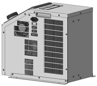
146 Series HEC-A Parts Description HEC2 Power connector Handle Communication connector RS-232C type 1 pc. RS-485 type 2 pcs. Handle Display/Operation panel Power switch Alarm connector External temperature sensor connector Circulating fluid outlet Filter Tank lid with gasket Circulating fluid level gauge Circulating fluid inlet Drain (circulating fluid drain port) HEC6 Power connector Handle Communication connector RS-232C type 1 pc. RS-485 type 2 pcs. Handle Display/Operation panel Power switch Alarm connector External temperature sensor connector Circulating fluid outlet Filter Tank lid with gasket Circulating fluid level gauge Circulating fluid inlet Drain (circulating fluid drain port) 136
147 OUT IN DRAIN P I SMC THERMO-CON C US CAN/CSA STD C22.2 NO.61.1 LI MODEL No. NTERT EK S T E D CM SERIAL No. INPUT VOLTAGE MAX CURRENT HEADQUARTER ETL LISTED CONFORMS TO CERTIFIED TO UL STD HEC2-A5B-F JT-****(JUN,25) 1Phase,AC1-24V to 5/6Hz 8A SMC CORPORATION ,Sotokannda,Chiyoda-ku, Tokyo 11-21,Japan OUT IN THERMO-CON MADE IN JAPAN DRAIN AC RS-232C ALARM EXT.SENSOR Peltier-Type Chiller Thermo-con (Air-cooled) Series HEC-A Dimensions Unit: inch (mm) HEC (436) 16.3 (414) 1.8 (46) 11.8 (3) R15.7 (4) HED WARNING HAZARDOUS VOLTAGE INSIDE Contact may cause electric shock,orburn. Do not remove the panel. No user serviceable parts inside. Refer all repaird to the manufacturer. CAUTION Please keep air filter clean as performance decreases with dust build up. AT SEL RET 2.2 (57) 5.6 (142) 8.3 (21) 9.5 (24) 1.6 (27) HRG Power cable (Accessory).16 x.2 (4 x 5) Warning/Caution label Handle 5.7 (145) 15.4 (39) Model no. label Display/Operation panel 6 Power switch Tank lid with gasket Air Communication connector Alarm output connector Power connector HRS HRZ HRZD HRW HEC HEB Air Handle External temperature sensor connector 11.7 (298) 5.7 (145) 4. (11) 2. (51) 15.5 (393) 15.2 (385) 13.7 (347) 1.2 (3) 3.8 (97) 1.9 (49) Circulating fluid outlet Rc1/ (281) 6.2 (157) Air HEC H L Air 1.6 (27) 1.6 (27) 13.7 (347) 11.8 (3) Foot (Accessory).5 (12) Filter cover Filter 12.6 (321) 14.3 (364) Circulating fluid inlet Rc1/4 Circulating fluid drain port (with plug) Rc1/4 Circulating fluid level gauge 6. (152) 1.1 (29).8 (21) 14.1 (358) 4 x Plastic foot Option (Fitting part) NPT fitting specification (-N, -FN) Circulating fluid outlet NPT1/4 Circulating fluid inlet NPT1/4 Circulating fluid drain port (with plug) NPT1/4 Power Cable (Accessory) Connector: IEC 632 C13 or equivalent Cable: 14AWG, O.D. ø8.4 Wire color Contents Black 1 to 24 VAC Black 1 to 24 VAC Green/Yellow PE Technical Data Related Products 78.8 (2) 137
148 OUT IN DRAIN P SMC THERMO-CON THERMO-CON MODEL No. HEC6-A5B SERIAL No. MP-****(Feb, 28) INPUT VOLTAGE 1Phase, 1-24V to 5/6Hz MAX CURRENT 1A HEADQUARTER SMC CORPORATION , Sotokanda, Chiyoda-ku, Tokyo 11-21, Japan MADE IN JAPAN OUT IN DRAIN AC RS-232C ALARM EXT.SENSOR Series HEC-A Dimensions HEC (455) 17. (433) 1.8 (46) 11. (28) R15.7 (4) Handle Power connector Power cable (Accessory) 15.4 (39) 15. (382) 14.2 (361) 6.3 (16) Model no. label Handle (48) Circulating fluid outlet Rc3/8 Air Circulating fluid inlet Rc3/8.7 (17) 4.1 (14) 6.7 (171) Tank lid with gasket 11. (278) Air HEC H L Communication connector Alarm output connector External temperature sensor connector Air Air 8.6 (219) 6.3 (16).4 (1) Foot (Accessory) Filter cover 13.6 (346) 15.1 (384) Filter Circulating fluid drain port (with plug) Rc1/4 Circulating fluid level gauge 1.3 (32) 1.4 (36) 14.2 (361) 6.9 (176) WARNING HAZARDOUS VOLTAGE INSIDE Contact may cause electric shock,orburn. Do not remove the panel. No user serviceable parts inside. Refer all repaird to the manufacturer. CAUTION Please keep air filter clean as performance decreases with dust build up. AT SEL RET 2.8 (72) 6.2 (157) 9.5 (24) 1.6 (27) 11.8 (3).16 x.2 (4 x 5) 14.6 (37) Display/Operation panel Power switch Warning/Caution label 13. (33) 11.3 (286) 1.5 (266) 9.7 (246) 14.2 (361) 4 x Plastic foot Option (Fitting part) NPT fitting specification (-N, -FN) Circulating fluid outlet NPT3/8 Circulating fluid inlet NPT3/8 Circulating fluid drain port (with plug) NPT1/4 Power Cable (Accessory) Connector: IEC 632 C13 or equivalent Cable: 14AWG, O.D. ø8.4 Wire color Contents Black 1 to 24 VAC Black 1 to 24 VAC Green/Yellow PE 78.8 (2) 138
149 Peltier-Type Chiller Thermo-con (Air-cooled) Series HEC-A Connectors 1. Power connector (AC) IEC 632 C14 or equivalent 1 2 Pin No Contents 1 to 24 VAC 1 to 24 VAC PE 3 2. Communication connector (RS-232C or RS-485) D-sub 9 pin (socket) Holding screw: M2.6 Pin No External sensor connector (EXT.SENSOR) D-sub 15 pin (socket) Holding screw: M2.6 Pin No Signal contents RS-232C RS-485 Unused BUS+ RD BUS SD Unused Unused Unused SG SG Unused Unused Signal contents Unused Terminal A of resistance temperature detector Terminal B of resistance temperature detector Terminal B of resistance temperature detector Unused FG HRW HRZD HRZ HRS HRG 4. Alarm output connector (ALARM) D-sub 9 pin (pin) Holding screw: M HEC Pin No Signal contents Contact a for output cut-off alarm (open when alarm occurs) Common for output cut-off alarm Contact b for output cut-off alarm (closed when alarm occurs) Unused Contact a for upper/lower temp. limit alarm (open when alarm occurs) Common for upper/lower temp. limit alarm Contact b for upper/lower temp. limit alarm (closed when alarm occurs) Unused HEB HED Technical Data Related Products 139
150 Series HEC-A Alarm This unit is equipped as standard with a function allowing 15 kinds of alarms to display on the LCD and can be read out by serial communication. Also, it can generate relay output for upper/lower temperature limit alarm and output cut-off alarm. Alarm Alarm code WRN ERR ERR1 ERR3 ERR4 ERR11 ERR12 Alarm description Upper/Lower temp. limit alarm CPU hung-up CPU check error Back-up data error EEPROM writing error DC power supply failure Internal temp. sensor high temp. error Operation status Continue Stop Stop Stop Stop Stop Stop Main reason The temperature has exceeded the upper or lower limit of the target temperature. The CPU has crashed due to noise, etc. The contents of the CPU cannot be read out correctly when the power supply is turned on. The contents of the back-up data cannot be read out correctly when the power supply is turned on. The data cannot be written to EEPROM. The DC power supply has failed (due to fan stop or abnormal high temperature) or the thermo-module has been short-circuited. The internal temperature sensor has exceeded the upper limit of cut-off temperature. Internal temp. sensor ERR13 low temp. error Stop The internal temperature sensor has exceeded the lower limit of cut-off temperature. ERR14 Thermostat alarm Stop The thermostat has been activated due to filter clog or fan/pump failure, etc. ERR15 Abnormal output alarm Continue The temperature cannot be changed even at 1% output due to overload or disconnection of the thermo-module. ERR16 Low flow rate alarm (option) Stop The flow rate of the circulating fluid has dropped. ERR17 Internal temp. sensor disconnection alarm Stop The internal temperature sensor has been disconnected or short-circuited. ERR18 External temp. sensor The external temperature sensor has been disconnected or short-circuited. (Only detected Continue disconnection alarm when in learning control or external tune control) ERR19 ERR2 Abnormal auto tuning alarm Low fluid level alarm Stop Stop Auto tuning has not been completed within 2 minutes. The amount of circulating fluid in the tank has dropped. Maintenance Maintenance of this unit is performed only in the form of return to and repair at SMC s site. As a rule, SMC will not conduct on-site maintenance. Separately, the following parts have a limited life and need to be replaced before the life ends. Parts Life Expectation Description Expected life Pump 3 to 5 years Fan DC power supply 5 to 1 years 5 to 1 years Possible failure The bearing is worn so the pump fails to transfer the circulating fluid, which results in temperature control failure. The bearing uses up lubrication and makes the fan unable to supply enough air, which deteriorates the cooling and heating capacity. The capacity of the electrolytic condenser decreases, and causes abnormal voltage which results in DC power supply failure and stops the Thermo-con. Display panel 5, hours (approx. 5 years) The display turns off when the backlight of the LCD reaches the end of its life. 14
151 F HEC Option symbol Series HEC-A Options With Flow Switch F With flow switch Note) Options have to be selected when ordering the Thermo-con. It is not possible to add them after purchasing the unit. This is an ON/OFF switch detecting low levels of the circulating fluid. When the fluid volume is 1 L/min. or less, ERR16 is displayed and the Thermo-con stops. This switch is installed between the circulating fluid inlet and the tank, and built into the Thermo-con. Refer to page 129. Type Aircooled Applicable model HEC2-A5-F HEC6-A5-F HRG N Option symbol NPT Thread HRS HEC N NPT thread HRZ The connection parts of circulating fluid piping, facility water piping and circulating fluid drain port are NPT thread type. Type Aircooled Applicable model HEC2-A5-N HEC6-A5-N Related Products HRZD Technical Data HED HEB HEC HRW 141
152 WARNING HAZARDOUS VOLTAGE INSIDE Contact may cause electric shock,orburn. Do not remove the panel. No user serviceable parts inside. Refer all repaird to the manufacturer. CAUTION Please keep air filter clean as performance decreases with dust build up. SMC THERMO-CON AT SEL RET WARNING HAZARDOUS VOLTAGE INSIDE Contact may cause electric shock,orburn. Do not remove the panel. No user serviceable parts inside. Refer all repaird to the manufacturer. CAUTION Please keep air filter clean as performance decreases with dust build up. SMC THERMO-CON AT SEL RET WARNING HAZARDOUS VOLTAGE INSIDE Contact may cause electric shock,orburn. Do not remove the panel. No user serviceable parts inside. Refer all repaird to the manufacturer. CAUTION Please keep air filter clean as performance decreases with dust build up. SMC THERMO-CON AT SEL RET WARNING HAZARDOUS VOLTAGE INSIDE Contact may cause electric shock,orburn. Do not remove the panel. No user serviceable parts inside. Refer all repaird to the manufacturer. CAUTION Please keep air filter clean as performance decreases with dust build up. SMC THERMO-CON AT SEL RET P P P P Series HEC-A Specific Product Precautions 1 Be sure to read this before handling. Refer to back page 1 for Safety Instructions and back pages 2 to 5 for Temperature Control Equipment Precautions. Warning System Design 1. This catalog shows the specifications of the Thermo-con. 1. Check detailed specifications in the separate Product Specifications, and evaluate the compatibility of the Thermo-con with customer s system. 2. Although the protection circuit as a single unit is installed, the customer is requested to carry out the safety design for the whole system. Handling Caution Radiation Air 1. The inlet for radiation air must not be exposed to particles and dust as far as possible. 2. Do not let the inlet and outlet for radiation air get closed. <HEC2> If radiation is prevented, the set temperature may not be achieved depending on the value of the set temperature and the load. Keep a space of 3.9 in (1 mm) for opened rear side or 7.9 in (2 mm) for closed rear side respectively. Warning 1. Thoroughly read the Operation Manual. Read the Operation Manual completely before operation, and keep this manual available whenever necessary. 2. If the set temperature is repeatedly changed by 5 F (1 C) or more, the Thermo-con may fail in short periods of time. Intake 3.9 in (1 mm) or more Discharge 3.9 in (1 mm) or more The rear side is opened. Operating Environment/Storage Environment Warning 1. Keep within the specified ambient temperature and humidity range. Also, if the set temperature is too low, condensation may form on the inside of the Thermo-con or the surface of piping even within the specified ambient temperature range. Dew condensation can cause failure, and so must be avoided by considering operating conditions. 2. The Thermo-con is not designed for clean room usage. It generates dust from the pump inside the unit and the cooling fan. 3. Low molecular siloxane can damage the contact of the relay. Use the Thermo-con in a place free from low molecular siloxane. <HEC6> Intake 7.9 in (2 mm) or more Intake 19.7 in (5 mm) or more Discharge 7.9 in (2 mm) or more Discharge 19.7 in (5 mm) or more The rear side is closed. The rear side is opened. Intake Discharge The rear side is closed in (5 mm) or more 19.7 in (5 mm) or more Note) The space must be 19.7 in (5 mm) or more. Be sure that the ambient temperature is within the specification range. 142
153 Series HEC-A Specific Product Precautions 2 Be sure to read this before handling. Refer to back page 1 for Safety Instructions and back pages 2 to 5 for Temperature Control Equipment Precautions. Caution Caution Radiation Air 3. If more than one Thermo-con is used, consider their arrangement so that the downstream sides of the Thermo-cons suck radiation air from the upstream sides. Otherwise, the performance at the downstream sides may deteriorate. Also, the set temperature may not be achieved depending on the value of the set temperature and the load. In such a case, take countermeasures such as changing the direction of the Thermo-cons to prevent the deterioration of performance. 4.If dust adheres to the filter, remove dust with a vacuum cleaner or a dry cloth. 5. Do not operate without the filter. Otherwise, dust may accumulate on the heat sink and electrical components, causing abnormal heating. Circulating Fluid 1. Use tap water or fluid which will not damage the wetted material. (Stainless steel 33, Stainless steel 34, EPDM, Polypropylene, PE, PPE, Ceramics, Polyurethane) 2. Deionized water (with an electrical conductivity of approx. 1 µs/cm) can be used, but may lose its electrical conductivity. Also, if a facility supplying deionized water is used, the Thermocon may be damaged by static electricity. 3. If deionized water is used, bacteria and algae may grow in short periods of time. If the Thermo-con is operated with bacteria and algae, its cooling capacity or the capacity of the pump may deteriorate. Exchange all deionized water regularly depending on the conditions (once a month as a guide). 4. If using a fluid other than water, please contact SMC beforehand. 5. The maximum operating pressure of circulating fluid circuit is 14.5 psi (.1 MPa). If this pressure is exceeded, leakage from the tank in the Thermo-con can result. 6. Select a pipe with a length and diameter which allow a flow rate of.26 gpm (1 L/min) or more (HEC2) or.79 gpm (3 L/min) or more (HEC6) for the circulating fluid. If the flow rate is less than these values, the Thermo-con cannot provide precise control, but also can fail because of the repeated cooling and heating operation. 7. A magnet driven pump is used as a circulat-ing pump. A fluid which contains metal powders such as iron powder cannot be used. 8. The Thermo-con must not be operated with-out circulating fluid. The pump can break due to idling. Caution Circulating Fluid 9. If the tank lid is opened after the supply of circulating fluid, the circulating fluid may spill out depending on the condition of external piping. 1. If an external tank is used, the circulating fluid may spill out from the internal tank lid depending on where the external tank is installed. Check that the internal tank has no leakage if using an external tank. 11. If there is a point where fluid is released to atmosphere externally (tank or piping), minimize the piping resistance at the circulating fluid return side. If the piping resistance is too large, the piping may be crushed, or the built-in circulator tank may be deformed or cracked because the pressure in the piping for return will become negative. The built-in circulator tank is made of resin (PE). Therefore, the tank may be crushed if the pressure is negative. Special attention must be paid if the flow rate of the circulating fluid is high. To avoid getting negative pressure less than 2.9 psi (.2 MPa), the piping for return should be as thick and short as possible to minimize the piping resistance. It is also effective to restrict the flow rate of circulating fluid or remove the gasket of internal tank for the release to atmosphere. 12. Fluorinated fluid is outside of the specifications. If it is used in the Thermo-con, static electricity will be generated by the flow of fluid. This static electricity may be discharged to the board of the Thermo-con, causing damage or operation failure and loss of data of such as set temperature. Also, as the specific gravity of the fluorinated fluid is 1.5 to 1.8 times of water, the pump will be overloaded, which also causes fluorinated fluid to be outside the specifications. Therefore, if fluorinated fluid is used, please contact SMC and we will introduce a suitable special product (water-cooled type). 13. Avoid operation with cavitation or bubbles due to low fluid level in the tank. This may shorten the pump life. 14. If clear water is used, it should satisfy the quality standards shown below. Clear Water (as Circulating Water) Quality Standards The Japan Refrigeration and Air Conditioning Industry Association JRA GL Cooling water system Circulating type Supply water Influence Item Unit Standard value Scale Corrosion generation ph (at 77 F (25 C)) Electrical conductivity (77 F) Chloride ion (Cl ) Sulfuric acid ion (SO 2 4 ) Acid consumption amount (at ph4.8) Total hardness Calcium hardness (CaCO 3 ) Ionic state silica (SiO 2 ) Iron (Fe) Copper (Cu) Sulfide ion (S 2 ) Ammonium ion (NH 4+ ) Residual chlorine (Cl) Free carbon (CO 2 ) [µs/cm] [mg/l] [mg/l] [mg/l] [mg/l] [mg/l] [mg/l] [mg/l] [mg/l] [mg/l] [mg/l] [mg/l] [mg/l] 6. to 8. 1 to 3 5 or less 5 or less 5 or less 7 or less 5 or less 3 or less.3 or less.1 or less Should not be detected..1 or less.3 or less 4. or less In the case of [MΩcm], it will be.3 to.1. : Factors that have an effect on corrosion or scale generation. Even if the water quality standards are met, complete prevention of corrosion is not guaranteed. Standard item Reference item HRG HRS HRZ HRZD HRW HEC HEB HED Technical Data Related Products 143
154 Caution Warning Series HEC-A Specific Product Precautions 3 Be sure to read this before handling. Refer to back page 1 for Safety Instructions and back pages 2 to 5 for Temperature Control Equipment Precautions. Communication 1. The set value can be written to EEPROM, but only up to approx. 1 million times. In particular, pay attention to how many of times the writing is performed using the communication function. Maintenance 1. Prevention of electric shock and fire Do not operate the switch with wet hands. Also, do not operate the Thermo-con with water left on it. 2. Action in the case of error If any error such as abnormal sounds, smoke, or bad smell occurs, cut off the power at once, and stop supplying and conveying fluid. Please contact SMC or a sales distributor to repair the Thermo-con. 3. Regular inspection Check the following items at least once a month. The inspection must be done by an operator who has sufficient knowledge and experience. a) Check of displayed contents. b) Check of temperature, vibration and abnormal sounds in the body of the Thermo-con. c) Check of the voltage and current of the power supply system. d) Check for leakage and contamination of the circulating fluid and intrusion of foreign objects to it, and subsequent replacement of the fluid. e) Check for flow condition, temperature and filter of radiation air. 144
155 Related Products Technical Data HED HEB HEC HRW HRZD HRZ HRS HRG 145

156 Peltier-Type Chiller Thermo-con (Water-cooled) Series HEC-W How to Order Note) Except HEC6, 12 RoHS 14 W, 32 W HEC 3 W 5 B Cooling capacity 1 14 W 3 32 W Radiating method W Water-cooled Power supply 5 1 to 24 VAC Specifications (For details, please consult our Product Specifications information.) Option Nil None F With flow switch N NPT thread L With level switch The option should be specified when ordering. Communication A RS-485 B RS-232C Select B when communication is not used. W Note 1) Model HEC1-W5A HEC1-W5B HEC3-W5A HEC3-W5B Cooling method Radiating method Control method Ambient temperature/humidity Circulating fluid Operating temp. range Cooling capacity Thermoelectric device (Thermo-module) Water-cooled Cooling/Heating automatic shift PID control 5 to 95 F (1 to 35 C), 35 to 8%RH (no condensation) Clear water, 2% ethylene glycol 5 to 14 F (1 to 6 C) (no condensation) 14 W Note 1) 32 Heating capacity 4 W Note 1) 77 W Note 1) Temperature stability Note 2) Pump capacity Tank capacity Port size Wetted parts material Temperature range Pressure range Required flow rate Note 3) Port size Wetted parts material Power supply Overcurrent protector ±.18 to.54 F (±.1 to.3 C) Refer to performance chart. Approx..32 gal (1.2 L) IN/OUT: Rc3/8 Drain: Rc1/4 (with plug) PPE, PP glass 1%, Alumina ceramics, Carbon, EPDM, Stainless steel 33, Stainless steel 34, PE, PP, NBR 5 to 95 F (1 to 35 C) (no condensation) Within 145 psi (1 MPa).8 to 1.9 gpm (3 to 7 L/min) IN/OUT: Rc3/8 Stainless steel 34 Single-phase 1 to 24 VAC ±1%, 5/6 Hz 1 A Current consumption 3.5 A (1 VAC) to 1.5 A (24 VAC) 5.5 A (1 VAC) to 2.5 A (24 VAC) Alarm Refer to alarm function. Communications RS-485 RS-232C RS-485 RS-232C Weight Approx lbs (12 kg) Approx lbs (13 kg) Accessories Safety standards Power cable, Foot for fixing, Splashproof cover CE marking, UL (NRTL) standards, SEMI Note 1) Circulating fluid/clear water conditions: Circulating fluid set temperature 68 F (2 C), Flow rate 1.3 gpm (5 L/min)., Facility water temperature 68 F (2 C), Flow rate 1.3 gpm (5 L/min)., Ambient temperature 77 F (25 C) Note 2) The indicated values are with a stable load without turbulence in the operating conditions. It may be out of this range in some other operating conditions. Note 3) The flow rate over or below the set range may deteriorate performance or generate noise. Circulating fluid system Facility water system Electrical system 146

157 Peltier-Type Chiller Thermo-con (Water-cooled) Series HEC-W How to Order 6 W, 12 W HEC 12 W 2 B Cooling capacity 6 6 W W Radiating method W Water-cooled Power supply 2 2 to 22 VAC Option Nil None N NPT thread The option should be specified when ordering. Communication A RS-485 B RS-232C Select B when communication is not used. Specifications (For details, please consult our Product Specifications information.) HRG HRS HRZ FC-3283) Note 3) Model HEC6-W2A HEC6-W2B HEC12-W2A HEC12-W2B Cooling method Radiating method Control method Ambient temperature/humidity Circulating fluid Note 1) Operating temperature range Cooling capacity Thermoelectric device (Thermo-module) Water-cooled Cooling/Heating automatic shift PID control 5 to 95 F (1 to 35 C), 35 to 8%RH (no condensation) Clear water, Fluorinated fluid (Fluorinert FC-3283, GALDEN HT135) 5 to 14 F (1 to 6 C) (no condensation) 6 W (Clear water), 4 W (Fluorinert FC-3283) Note 2) 12 W (Clear water), 8 W (Fluorinert Heating capacity 9 W (Clear water), 6 W (Fluorinert FC-3283) Note 2) 22 W (Clear water), 15 W (Fluorinert FC-3283) Note 3) Temperature stability Note 4) Pump capacity ±.18 to.54 F (±.1 to.3 C) Refer to performance chart. Tank capacity Approx..8 gal (3 L) Approx. 1.3 gal (5 L) Circulating fluid system Port size Wetted parts material Temperature range 5 to 95 F (1 to 35 C) (no condensation) Pressure range Within 145 psi (1 MPa) Note 5) Required flow rate 2.1 to 2.6 gpm(8 to 1 L/min) 2.6 to 4. gpm (1 to 15 L/min) Port size IN/OUT: Rc3/8 IN/OUT: Rc1/2 Wetted parts material Stainless steel 33, Stainless steel 34 Power supply Single-phase 2 to 22 VAC ±1%, 5/6 Hz Overcurrent protector 1 A 15 A Current consumption 5 A 1 A Alarm Refer to alarm function. Communications RS-485 RS-232C RS-485 RS-232C Weight Approx. 55 lbs (25 kg) (including foot for fixing) Approx. 88 lbs (4 kg) (including foot for fixing) Accessories Power cable, Foot for fixing Safety standards CE marking Note 1) Fluorinert is a trademark of 3M and GALDEN is a registered trademark of Solvay Solexis, Inc. Regarding the fluid other than the above, please consult with SMC. Note 2) Conditions: Set temperature 77 F (25 C), Facility water temperature 68 F (2 C), Facility water flow rate 2.1 gpm (8 L/min), Ambient temperature 77 F (25 C). Note 3) Conditions: Set temperature 77 F (25 C), Facility water temperature 68 F (2 C), Facility water flow rate 2.6 gpm (1 L/min), Ambient temperature 77 F (25 C). Note 4) The indicated values are with a stable load without turbulence in the operating conditions. It may be out of this range in some other operating conditions. Note 5) The flow rate over or below the set range may deteriorate performance or generate noise. Facility water system Electrical system IN/OUT: Rc3/8 Drain: Rc1/4 (with plug) Stainless steel 33, Stainless steel 34, EPDM, Ceramics, PPS glass 3%, Carbon, PE, Polyurethane IN/OUT: Rc3/4 Drain: Rc1/4 (with plug) Stainless steel 33, Stainless steel 34, EPDM, Ceramics, PP, PE, Polyurethane, SiC, PPS HRZD HRW HEC HEB HED Technical Data Related Products 147
158 Series HEC-W Cooling Capacity HEC1 Cooling capacity (W) 6 Circulating fluid: Clear water F 5 Facility Facility water: 5 F (1 C) water: 4 68 F (2 C) 3 Facility water: 2 86 F (3 C) 1 Facility water flow rate: 1.3 gpm (5 L/min) Circulating fluid temperature ( C) HEC3 1 Circulating fluid: Clear water F Cooling capacity (W) The values shown on the performance chart are not guaranteed, but typical. Allow margins for safety when selecting the model Circulating fluid: 2% ethylene glycol F Facility water: 68 F (2 C) Facility water flow rate: 1.3 gpm (5 L/min) Circulating fluid temperature ( C) Circulating fluid: 2% ethylene glycol F Cooling capacity (W) HEC6 Facility water: 5 F (1 C) Facility water: 68 F (2 C) Facility water: 86 F (3 C) Facility water flow rate: 1.3 gpm (5 L/min) Circulating fluid temperature ( C) Circulating fluid: Clear water Cooling capacity (W) 8 6 Facility water: 68 F (2 C) 4 2 Facility water flow rate: 1.3 gpm (5 L/min) Circulating fluid temperature ( C) Circulating fluid: FC F F Cooling capacity (W) 1 5 Facility water: 5 F (1 C) Facility water: 68 F (2 C) Facility water: 95 F (35 C) Cooling capacity (W) 1 5 Facility water: 5 F (1 C) Facility water: 68 F (2 C) Facility water: 95 F (35 C) HEC12 Cooling capacity (W) Facility water flow rate: 2.1 gpm (8 L/min) Circulating fluid temperature ( C) F Facility Facility water: 5 F (1 C) water: 68 F (2 C) Facility water: 95 F (35 C) Circulating fluid temperature ( C) Circulating fluid: Clear water Facility water flow rate: 2.6 gpm (1 L/min) Cooling capacity (W) Facility water flow rate: 2.1 gpm (8 L/min) Circulating fluid temperature ( C) Circulating fluid: FC F Facility water: 5 F (1 C) Facility water: 68 F (2 C) Facility water: 95 F (35 C) 5 Facility water flow rate: 2.6 gpm (1 L/min) Circulating fluid temperature ( C)
159 Heating Capacity HEC1 Heating capacity (W) The values shown on the performance chart are not guaranteed, but typical. Allow margins for safety when selecting the model. Circulating fluid: Clear water F F 6 Facility water flow rate: 13. gpm (5 L/min) Facility water flow rate: 1.3 gpm (5 L/min) 1 Facility water: 5 F (1 C) Circulating fluid temperature ( C) HEC3 1 Facility water: 86 F (3 C) Facility water: 68 F (2 C) Circulating fluid: Clear water F Facility water flow rate: 1.3 gpm (5 L/min) Peltier-Type Chiller Thermo-con (Water-cooled) Heating capacity (W) Series HEC-W Circulating fluid: 2% ethylene glycol Facility water: 68 F (2 C) Circulating fluid temperature ( C) Circulating fluid: 2% ethylene glycol F Facility water flow rate: 1.3 gpm (5 L/min) HRG HRS Heating capacity (W) Facility water: 86 F (3 C) Facility water: 68 F (2 C) Facility water: 5 F (1 C) Heating capacity (W) Facility water: 68 F (2 C) HRZ HRZD HEC Circulating fluid temperature ( C) Circulating fluid: Clear water Circulating fluid temperature ( C) Circulating fluid: FC-3283 HRW F Facility water flow rate: 2.1 gpm (8 L/min) F Facility water flow rate: 2.1 gpm (8 L/min) Heating capacity (W) HEC12 Heating capacity (W) Circulating fluid temperature ( C) Facility water: 95 F (35 C) Facility water: 68 F (2 C) Facility water: 5 F (1 C) Circulating fluid: Clear water F F 3 Facility water flow rate: 2.6 gpm (1 L/min) Facility water flow rate: 2.6 gpm (1 L/min) Facility water: 95 F (35 C) Facility water: 68 F (2 C) 5 Facility water: 5 F (1 C) Circulating fluid temperature ( C) Heating capacity (W) Heating capacity (W) Facility water: 68 F (2 C) Facility water: 5 F (1 C) Circulating fluid temperature ( C) Facility water: 5 F (1 C) Circulating fluid temperature ( C) Facility water: 95 F (35 C) Circulating fluid: FC-3283 Facility water: 95 F (35 C) Facility water: 68 F (2 C) HEC HEB HED Technical Data Related Products 149
160 Series HEC-W Pump Capacity (Thermo-con Outlet) HEC1/3 Since a DC pump is used, the unit is not affected by power requirements..15 MPa 2 psi gpm Discharge pressure % ethylene glycol Water Circulating fluid flow rate (L/min) HEC6 Since a DC pump is used, the unit is not affected by power requirements..15 MPa gpm 2 psi Discharge pressure Water Fluorinert FC Circulating fluid flow rate (L/min) Pressure Loss in Facility Water Circuit HEC1.14 MPa gpm 2 psi Facility water flow rate (L/min) Pressure loss HEC6.25 MPa 3.5 psi Pressure loss gpm Facility water flow rate (L/min) HEC12.3 MPa 4 psi Discharge pressure Hz.15 2 Fluorinert FC Hz Water 6Hz 5Hz Circulating fluid flow rate (L/min) HEC3.25 MPa 3.5 psi Pressure loss HEC12.6 MPa 9. psi Pressure loss gpm gpm Facility water flow rate (L/min) gpm Facility water flow rate (L/min)
 Facility water outlet Facility water inlet Handle Circulating fluid inlet Circulating fluid level gauge External")
 Power connector (Connect the attached power")
 Splashproof cover HRS HRZ HEC6/12 HRZD Power switch Display/Operation panel Tank lid (with gasket) Circulating fluid level")
 Cooling fan Communication connector RS-232C type 1 pc. RS-485 type 2 pcs.")
161 Peltier-Type Chiller Thermo-con (Water-cooled) Series HEC-W Parts Description HEC1/3 Display/Operation panel Tank lid (with O-ring) Facility water outlet Facility water inlet Handle Circulating fluid inlet Circulating fluid level gauge External temperature sensor connector Alarm output connector Communication connector RS-232C type 1 pc. RS-485 type 2 pcs. HRG Power switch Circulating fluid outlet Drain (Circulating fluid drain port) Power connector (Connect the attached power cable.) Splashproof cover HRS HRZ HEC6/12 HRZD Power switch Display/Operation panel Tank lid (with gasket) Circulating fluid level gauge Handle Facility water outlet Facility water inlet Splashproof cover Circulating fluid outlet Circulating fluid inlet Drain (Circulating fluid drain port) Cooling fan Communication connector RS-232C type 1 pc. RS-485 type 2 pcs. Alarm output connector External temperature sensor connector Power connector (Connect the attached power cable.) HED HEB HEC HRW Related Products Technical Data 151
162 Series HEC-W Dimensions HEC1-W5 HEC3-W5 Unit: Inch (mm) Warning/Caution label 7.2 (182) (1.26(32)) 4.7 (12) Tank lid (with O-ring) (1.7 (45.5)) (2.2 (55)).4 (1) 13.7 (348) Foot (Accessory).16 (4) x width.2 (5) Display/ Operation panel Power switch (7.5 (19)) 7.2 (184) 1. ((25)) ø2.8 (72) Power Cable (Accessory) Circulating fluid level gauge 9.6 (245) 7.8 (197) 8.4 (214) 12.6 (321) Handle 3.9 (1) (1.1 (27)) (.51 (13)) (1.2 (3)) 1.2 (3) 14.5 (368) 1.6 (41) Circulating fluid inlet Rc3/8 8.7 (221) 6.3 (16) 5.6 (143) 1.1 (28) Drain (Circulating fluid drain port) Splashproof cover (Accessory) For NPT thread specification (-N), all fittings (including those at the circulating fluid drain port) are made of NPT..8 (19) DRAIN 1.1 (28) 2.5 (64) 3.3 (84) 4.1 (14) IN OUT IN RADIATING WATER RECIRCULATING WATER OUT 5.8 (148) EXT.SENSOR ALARM RS-232C AC Model no. label 5.9 (15) 5. (128) 3.2 (82) 1.5 (37) Facility water outlet Rc3/8 Facility water inlet Rc3/8 Circulating fluid outlet Rc3/8 External temperature sensor connector Alarm output connector Power connector Communication connector Connector: IEC 632 C13 or equivalent Cable: 14AWG, O.D. ø8.4 Wire color Contents Black 1 to 24 VAC Black 1 to 24 VAC Green/Yellow PE 78.7 (2) Power cable (Accessory) 152
163 Peltier-Type Chiller Thermo-con (Water-cooled) Series HEC-W Dimensions HEC6-W2 Unit: inch (mm) Foot (Accessory) Power switch 17.9 (455).5 (13) 8.4 (214) (.5 (13)).16 x.28 (4 x 7) 17. (433) 18. (458) Display/ Operation panel 9.5 (24) 9.7 (246) Foot (Accessory) Warning/Caution label HRG HRS HRZ HEC H L Circulating fluid level gauge Tank lid with gasket 19. (482) Handle 1.6 (4) Air 15. (382) 15.4 (39) Facility water outlet Rc3/ (339) Circulating fluid outlet Rc3/8 Circulating fluid inlet 8.1 (27) Rc3/8 5.8 (146.5) Model no. label 1.1 (28.5) Circulating fluid drain port Rc1/4 (with plug) RECIRCULATING FLUID DRAIN 8. (24) 6.6 (168) 5. (128) OUT RADIATING WATER OUT IN IN 5.2 (133) 5.8 (148) Facility water inlet Rc3/8 2. (5) RS-232C ALARM EXT.SENSOR AC 1.3 (32) Fan 3.1 (8) Communication connector 11.9 (33) Alarm output connector 7.8 (198) 6.6 (168) External temperature 5. (128) sensor connector 2.9 (73) Power connector HEB HEC HRW HRZD For NPT thread specification (-N), all fittings (including those at the circulating fluid drain port) are made of NPT. HED Power Cable Connector: IEC 632 C13 or equivalent Cable: 14AWG, O.D. ø8.4 Wire color Contents Black 2 to 22 VAC Black 2 to 22 VAC Green/Yellow PE 78.7 (2) Power cable (Accessory) Technical Data Related Products 153
164 Series HEC-W Dimensions HEC12-W2 Unit: Inch (mm) Foot (Accessory) Power switch 2.6 (523) 19.7 (51) 7.5 (19) 11.8 (3) 12. (36) 2.2 (55) (2.2 (55)).16 x.28 (4 x 7) 2.7 (526) Display/ Operation panel Foot (Accessory) Warning/Caution label Circulating fluid level gauge Tank lid with gasket Handle 1.6 (4) Facility water outlet Rc1/2 9.8 (248) 8.2 (28) 5.8 (148) Circulating fluid outlet Rc3/4 2. (5) HEC H L Air 17.3 (44) 17.6 (448) 15.9 (44) 12.8 (326) 11. (281) Facility water inlet Rc1/2 6.5 (165) 1.1 (28.5) DRAIN OUT RADIATING WATER IN OUT RECIRCULATING FLUID IN RS-232C ALARM EXT.SENSOR AC Fan 3.1 (8.) 14.2 (361) 7.8 (198) 6.6 (168) 5. (128) 2.6 (67) Communication connector Alarm output connector External temperature sensor connector Power connector 21.7 (55) Circulating fluid drain port Rc1/4 (with plug) 1.9 (277) Model no. label 5.2 (131) 1.6 (4) Circulating fluid inlet Rc3/4 For NPT fitting specification (-N), all fittings (including those at the circulating fluid drain port) are made of NPT. Power Cable Connector: DDK CE5-6A18-1SD-D-BSS or equivalent Cable: 14AWG, O.D. ø8.4 Wire color Black Black Green/Yellow Contents 2 to 22 VAC 2 to 22 VAC PE 78.7 (2) Power cable (Accessory) 154
165 Peltier-Type Chiller Thermo-con (Water-cooled) Series HEC-W Connectors HEC6-W2/1-W5/3-W5 1. Power connector (AC) IEC 632 C14 or equivalent HEC6-W2 HEC1-W5 HEC3-W5 3 Pin No Contents 2 to 22 VAC 2 to 22 VAC PE Pin No Contents 1 to 24 VAC 1 to 24 VAC PE Communication connector (RS-232C or RS-485) D-sub 9 pin (socket) Holding screw: M2.6 HRG Pin No Signal contents RS-232C RS-485 Unused BUS+ RD BUS SD Unused Unused Unused SG SG Unused Unused HRS HRZ 3. External sensor connector (EXT.SENSOR) D-sub 15 pin (socket) Holding screw: M2.6 Pin No Signal contents Unused Terminal A of resistance temperature detector Terminal B of resistance temperature detector Terminal B of resistance temperature detector Unused FG HRZD HRW 4. Alarm output connector (ALARM) D-sub 9 pin (pin) Holding screw: M2.6 HEC Pin No Signal contents Contact a for output cut-off alarm (open when alarm occurs) 3 4 Common for output cut-off alarm Contact b for output cut-off alarm (closed when alarm occurs) Unused Contact a for upper/lower temp. limit alarm (open when alarm occurs) Common for upper/lower temp. limit alarm Contact b for upper/lower temp. limit alarm (closed when alarm occurs) Unused HEB HED HEC12-W2 Power connector (AC) DDK CE5-2A18-1PD-D or equivalent Technical Data Pin No. A B C D Contents 2 to 22 VAC 2 to 22 VAC Unused PE D C A B Related Products Other connectors are the same as those for the HEC6-W2. 155
166 Series HEC-W Alarm This unit is equipped as standard with a function allowing 15 kinds of alarms to display on the LCD and can be read out by serial communication. Also, it can generate relay output for upper/lower temperature limit alarm and output cut-off alarm. Alarm code WRN ERR ERR1 ERR3 ERR4 ERR11 ERR12 ERR13 ERR14 ERR15 ERR16 ERR17 ERR18 Alarm description Upper/Lower temp. limit alarm CPU hung-up CPU check error Back-up data error EEPROM writing error DC power supply failure Internal temp. sensor high temp. error Internal temp. sensor low temp. error Thermostat alarm Abnormal output alarm Pump failure 1 or low circulating fluid level alarm 2 Internal temp. sensor disconnection alarm External temp. sensor disconnection alarm Operation status Continue Stop Stop Stop Stop Stop Stop Stop Stop Continue Stop Stop Continue Main reason The temperature has exceeded the upper or lower limit of the target temperature. The CPU has crashed due to noise, etc. The contents of the CPU cannot be read out correctly when the power supply is turned on. The contents of the back-up data cannot be read out correctly when the power supply is turned on. The data cannot be written to EEPROM. The DC power supply has failed (due to abnormal high temperature) or an irregular voltage has occurred or the thermo-module has been short-circuited. The internal temperature sensor has exceeded the upper limit of cut-off temperature. The internal temperature sensor has exceeded the lower limit of cut-off temperature. The thermostat has been activated due to insufficient of the facility water or high temperature. The temperature cannot be changed even at 1% output due to overload or disconnection of the thermo-module. The pump has been overloaded 1 or the flow switch is activated 2. The internal temperature sensor has been disconnected or short-circuited. The external temperature sensor has been disconnected or short-circuited. (Only detected when in learning control or external tune control.) ERR19 ERR2 Abnormal auto tuning alarm Low fluid level alarm 3 Stop Stop Auto tuning has not been completed within 2 minutes. The amount of circulating fluid in the tank has dropped and the level switch is activated. 1 The HEC12 only 2 Optional for the HEC1 and HEC3 only (Not available for the HEC6) 3 Optional for the HEC1 and HEC3 Maintenance Maintenance of this unit is performed only in the form of return to and repair at SMC s site. As a rule, SMC will not conduct on-site maintenance. Separately, the following parts have a limited life and need to be replaced before the life ends. Parts Life Expectation Description Pump Fan DC power supply Display panel Expected life Possible failure 3 to 5 years The bearing is worn so the pump fails to transfer the circulating fluid, which results in temperature control failure. The bearing uses up lubrication and makes the fan unable to supply enough air, which increases the internal temperature of the Thermo-con, and activates the overheat protection of the power supply and generates the alarm. 5 to 1 years The capacity of the electrolytic condenser decreases, and causes abnormal voltage which results in DC power supply 5 to 1 years failure and stops the Thermo-con. 5, hours The display turns off when the backlight of the LCD reaches the end of its life. (approx. 5 years) 156
167 F HEC Option symbol Series HEC-W Options With Flow Switch F With flow switch Note) Options have to be selected when ordering the Thermo-con. It is not possible to add them after purchasing the unit. This is an ON/OFF switch detecting low levels of the circulating fluid. When the fluid volume is 1 L/min. or less, ERR16 is displayed and the Thermo-con stops. This switch is installed between the circulating fluid inlet and the tank, and built into the Thermo-con. Refer to page 129. Type Watercooled Applicable model HEC1-W5-F HEC3-W5-F HRG N Option symbol NPT Thread HRS HEC N NPT thread HRZ The connection parts of circulating fluid piping, facility water piping and circulating fluid drain port are NPT thread type. L HEC Option symbol With Level Switch L With level switch This switch is used to detect a LOW level of tank fluid. When the fluid level becomes below the LOW level, ERR2 is displayed and the Thermo-con stops. This switch is installed in the circulating fluid tank and built into the Thermo-con. Refer to page 129. Type Watercooled Type Watercooled Applicable model HEC1-W5-N HEC3-W5-N HEC6-W2-N HEC12-W2-N Applicable model HEC1-W5-L HEC3-W5-L Other models include a level switch as standard equipment. Related Products HED HEB HEC HRW HRZD Technical Data 157
168 Series HEC-W Specific Product Precautions 1 Be sure to read this before handling. Refer to back page 1 for Safety Instructions and back pages 2 to 5 for Temperature Control Equipment Precautions. Warning 1. This catalog shows the specifications of the Thermo-con. 1. Check detailed specifications in the separate Product Specifications, and evaluate the compatibility of the Thermo-con with customer s system. 2. Although the protection circuit as a single unit is installed, the customer is requested to carry out the safety design for the whole system. Warning System Design Operating Environment/Storage Environment Warning Handling 1. Thoroughly read the Operation Manual. Read the Operation Manual completely before operation, and keep this manual available whenever necessary. 2. If the set temperature is repeatedly changed by 5 F (1 C) or more, the Thermo-con may fail in short periods of time. 1. Keep within the specified ambient tempera-ture and humidity range. Also, if the set temperature is too low, condensation may form on the inside of the Thermo-con or the surface of piping even within the specified ambient temperature range. Dew condensation can cause failure, and so must be avoided by considering operating conditions. 2. The Thermo-con is not designed for clean room usage. The pump and fan generate dust. 3. Low molecular siloxane can damage the contact of the relay. Use the Thermo-con in a place free from low molecular siloxane. 158 Operating Environment/Storage Environment Warning 4. Installation conditions If the space for the intake and discharge of air is insufficient, the amount of transferred air will decrease, which can impair the performance and life of the product. Therefore, keep the conditions illustrated below for installation. Also, if ambient temperature is expected to be over 95 F (35 C), vent or exhaust air to prevent the increase of ambient temperature over 95 F (35 C). <HEC6/12> Intake 3.9 in (1 mm) or more Discharge Leave space 5.9 in (15 mm) ormore Intake 3.9 in (1 mm) or more Leave space 3.9 in Intake (1 mm) or <HEC1/3> more It is not necessary to leave space for ventilation. Install the product while taking working space for installation and maintenance into account. However, ventilation must be also considered so th at ambient temperature does not excessively rise. Caution Facility Water 1. If the temperature of the facility water is too low, it can cause formation of dew condensation inside the heat exchanger. Supply facility water with a temperature over the atmospheric dew point to avoid the formation of dew condensation. 2. If the facility water piping is connected to multiple machines, the facility water exchanges heat at the upstream side and its temperature will become higher as it goes downstream. Limit the number of connected Thermo-cons to two per facility water system, and if more than two Thermo-cons are to be connected, increase the number of systems. Circulating Fluid Caution 1. Use tap water or fluid which will not damage the wetted parts material as described in this catalog s specifications. (PPE, PP glass 1%, Alumina ceramics, Carbon, EPDM, Stainless steel 33, Stainless steel 34, PE, PP, NBR) 2. Deionized water (with an electrical conductivity of approx. 1 µs/cm) can be used, but may lose its electrical conductivity.
169 Series HEC-W Specific Product Precautions 2 Be sure to read this before handling. Refer to back page 1 for Safety Instructions and back pages 2 to 5 for Temperature Control Equipment Precautions. Caution Circulating Fluid 3. If deionized water is used, bacteria and algae may grow in a short period. If the Thermo-con is operated with bacteria and algae, its heat exchanging capacity or the capacity of the pump may deteriorate. Exchange all deionized water regularly depending on the conditions (once a month as a guide). 4. If using a fluid other than this catalog, please contact SMC beforehand. 5. The maximum operating pressure of circulating fluid circuit is 14.5 psi (.1 MPa). If this pressure is exceeded, leakage from the tank in the Thermo-con can result. 6. Select a pipe with a length and diameter which allow a flow rate of.8 gpm (3 L/min) or more for the circulating fluid. If the flow rate is less than.8 gpm (3 L/min), the Thermo-con cannot provide precise control, but also can fail because of the repeated cooling and heating operation. 7. A magnet driven pump is used as a circulat-ing pump. A fluid which contains metal powders such as iron powder cannot be used. 8. The Thermo-con must not be operated with-out circulating fluid. The pump can break due to idling. 9. If the tank lid is opened after the supply of circulating fluid, the circulating fluid may spill out depending on the condition of external piping. 1. If an external tank is used, the circulating fluid may spill out from the internal tank lid depending on where the external tank is installed. Check that the internal tank has no leakage if using an external tank. 11. If there is a point where fluid is released to atmosphere externally (tank or piping), minimize the piping resistance at the circulating fluid return side. If the piping resistance is too large, the piping may be crushed, or the built-in circulator tank may be deformed or cracked because the pressure in the piping for return will become negative. The built-in circulator tank is made of resin (PE). Therefore, the tank may be crushed if the pressure is negative. Special attention must be paid if the flow rate of the circulating fluid is high. To avoid getting negative pressure less than 2.9 psi (.2 MPa), the piping for return should be as thick and short as possible to minimize the piping resistance. It is also effective to restrict the flow rate of circulating fluid or remove the gasket of internal tank for the release to atmosphere. 12. If fluorinated fluid is used in the Thermo-con (HEC6/12), static electricity will be generated by the flow of fluid. This static electricity may be discharged to the board of the Thermo-con, causing damage or operation failure and loss of data of such as set temperature. Ground pipe in order to remove static electricity. 13. Avoid operation with cavitation or bubbles due to low fluid level in the tank. This may shorten the pump life. Circulating Fluid Caution 14. If clear water is used, it should satisfy the quality standards shown below. Clear Water (as Circulating Water) Quality Standards The Japan Refrigeration and Air Conditioning Industry Association JRA GL Cooling water system Circulating type Supply water Influence Item Unit Standard value Scale Corrosion generation Standard item Reference item ph (at 77 F (25 C)) Electrical conductivity (77 F) Chloride ion (Cl ) Sulfuric acid ion (SO 2 4 ) Acid consumption amount (at ph4.8) Total hardness Calcium hardness (CaCO 3 ) Ionic state silica (SiO 2 ) Iron (Fe) Copper (Cu) Sulfide ion (S 2 ) Ammonium ion (NH 4+ ) Residual chlorine (Cl) Free carbon (CO 2 ) [µs/cm] [mg/l] [mg/l] [mg/l] [mg/l] [mg/l] [mg/l] [mg/l] [mg/l] [mg/l] [mg/l] [mg/l] [mg/l] 6. to 8. 1 to 3 5 or less 5 or less 5 or less 7 or less 5 or less 3 or less.3 or less.1 or less Should not be detected..1 or less.3 or less 4. or less In the case of [MΩcm], it will be.3 to.1. : Factors that have an effect on corrosion or scale generation. Even if the water quality standards are met, complete prevention of corrosion is not guaranteed. Caution Warning Communication 1. The set value can be written to EEPROM, but only up to approx. 1 million times. In particular, pay attention to how many of times the writing is performed using the communication function. Maintenance 1. Prevention of electric shock and fire Do not operate the switch with wet hands. Also, do not operate the Thermo-con with water left on it. 2. Action in the case of error If any error such as abnormal sounds, smoke, or bad smell occurs, cut off the power at once, and stop supplying and conveying fluid. Please contact SMC or a sales distributor to repair the Thermo-con. 3. Regular inspection Check the following items at least once a month. The inspection must be done by an operator who has sufficient knowledge and experience. a) Check of displayed contents. b) Check of temperature, vibration and abnormal sounds in the body of the Thermo-con. c) Check of the voltage and current of the power supply system. d) Check for leakage and contamination of the circulating fluid and intrusion of foreign objects to it, and subsequent replacement of water. e) Check for leakage, quality change, flow rate and temperature of facility water. 159 HRG HRS HRZ HRZD HRW HEC HEB HED Technical Data Related Products
170 16

171 Peltier-Type Thermoelectric Bath Series HEB Accurately controls the temperature of liquid in the bath. Temperature stability: ±.18 F Temperature distribution: ±.36 F in the bath Environmentally friendly and refrigerant-free Heaterless Function to detect abnormal heating and temperature sensor errors comes standard. Light and compact Greatly reduced vibration and operating noise when compared with the refrigerated type. W7.9 IN X H13.1 X D8.1 IN W2 x H332 x D27 RoHS HRG HRS HRW HRZ HRZD W9.8 in x H 7.1 in x D13.4 in W25 mm x H18 mm x D34 mm HEC Peltier element Circulating fluid Water, Fluorinated liquid Fluorinert GALDEN HEB HED Controller Applications Chemicals for MOCVD Diffusion gas Various samples, materials and parts Chemicals and liquids with high viscosity Technical Data Related Products Facility water outlet Facility water inlet Circulating pump 161
172 Features Exclusively developed dual tank construction to provide consistent temperature at any position in the bath Peltier element (Thermo-module, Thermoelectric device) Temperature sensor Accurate display by measuring the circulating fluid with a temperature sensor directly Circulating pump Application Examples Semiconductor Various tests Physical and chemical analysis Various chemical processes Evaporation of chemicals for MOCVD Temperature control of diffusion gas Thermal test with immersion Temperature control of various samples, materials and parts Indirect temperature control of chemicals and liquids with high viscosity Principle of Peltier Device (Thermo-module, Thermoelectric device) A Peltier device (thermo-module, thermoelectric device) is a plate type element, inside which P-type semiconductors and N-type semiconductors are located alter-nately. If direct current is supplied to the Peltier device, heat is transferred inside the device, and one face generates heat and increases temperature while the other face sucked heat and decreases temperature. Therefore, changing the direction of the current supplied to the Peltier device can achieve heating and cooling operation. This method has a fast response and can shift quickly between heating and cooling, so temperature can be controlled very precisely. Cooling Heat suction (cooling) Recirculating fluid Electron flow N P Facility water Current Heat radiation (heating) DC power supply Electron hole flow Heating Heat generation (heating) Recirculating fluid Electron flow N P Facility water Current Heat suction (cooling) DC power supply Electron hole flow 162
 x H7.")
173 Peltier-Type Thermoelectric Bath Series HEB RoHS How to Order Combination (Controller + Liquid tank) HEB C 2 W A 1 Shape of bath C Round Cooling capacity 2 14 W Option Nil Rc1/4 N NPT1/4 The option should be specified when ordering. Controller Liquid tank HRG HRS HRZ Radiating method W Water-cooled Liquid tank size 1 ø5.1 in (13 mm) x H7.1 in (18 mm) Communication A RS-485 B RS-232C HRZD Liquid tank HEB C 2 H W 1 Shape of bath C Round Cooling capacity 2 14 W Option Nil Rc1/4 N NPT1/4 The option should be specified when ordering. HRW HEC HEB Liquid tank Radiating method W Water-cooled Liquid tank size 1 ø5.1 in (13 mm) x H7.1 in (18 mm) HED Controller HEBC2 C A Controller Communication A RS-485 B RS-232C Technical Data Related Products 163
174 Series HEB Specifications (For details, please consult our Product Specifications information.) Model HEBC2-WA1 HEBC2-WB1 Cooling method Radiating method Control method Ambient temperature/humidity Peltier device (Thermo-module, Thermoelectric device) Liquid tank: Water-cooled, Controller: Forcible air-cooled Cooling/Heating automatic shift PID control 5 to 95 F (1 to 35 C), 35 to 8%RH Note 1) Application fluid Clear water, Fluorinated liquid (Fluorinert FC-3283, GALDEN HT135, HT2) Set temperature range Note 1) Note 5) 5. to 14. F ( 15. to 6. C) (41 to 14 F (5 to 6 C for water)) Cooling capacity Note 2) 14 W (Water) Heating capacity Note 2) 3 W (Water) Temperature stability Note 3) ±.17 F ( ±.1 C) Temperature distribution Note 3) ±.36 F ( ±.2 C) Tank dimensions Internal diameter ø13 x Liquid level 188 mm Temperature 5 to 95 F (1 to 35 C) (no condensation) Pressure range Within 73 psi (.5 MPa) Note 4) Flow rate.8 to 1.3 gpm (3 to 5 L/min) Port size IN/OUT: Rc1/4 Wetted parts material Stainless steel 33, Stainless steel 34, FEP, A663 (anodized) Power supply Single-phase 1 to 24 VAC, 5/6 Hz Overcurrent protector 1 A Current consumption 4 A (1 VAC) to 2 A (24 VAC) Circulating fluid system Facility water system Electrical system Communications Weight Alarm (With alarm output connector) Accessories Safety standards RS-485 1) Overheating of liquid tank (which activates the thermostat) 2) Controller output voltage reduction 3) Controller fan rotation stopped RS-232C Liquid tank: Approx lbs (8.5 kg) Controller: Approx lgs (6.5 kg) Power cable (2 m), DC cable, Signal cable (3 m each) CE marking, UL (NRTL) standard Note 1) GALDEN is a trademark of Solvay Solexis and Fluorinert is a trademark of 3M. For other fluids, please contact SMC. Note 2) Determined under the following conditions: water as the recirculating fluid, set temperature 77 F (25 C), facility water temperature 77 F (25 C), flow rate.8 gpm (3 L/min), ambient temperature 77 F (25 C), and sealed from outside air with a lid. Note 3) Differs depending on the operating conditions. Note 4) An appropriate range is from.8 to 1.3 gpm (3 to 5 L/min). To prevent damage to the radiating system, do not supply a flow over the maximum flow rate of 2.11 gpm (8 L/min). Note 5) When the temperature is set high, the liquid temperature inside of the liquid tank and the temperature inside of the thermostat could differ greatly depending on the heating mode at start-up, and the thermostat could then begin operating and stop the output. Confirm that there is no problem by carrying out an operating test beforehand. 164
 F 8 2 (Liquid temperature: 77 F (25 C)) Facility water temperature: 77 F (25 C) 15 Facility water flow rate:.")
 65 6 Fluorinert FC-3283 55 13 5 Water 45 GALDEN Ambient temperature: 77 (25 C) 11 HT2 4 Liquid level: 7.")
 9 Shut out from outside with a lid 25 (polystyrene foam) 2 7 1 2 3 4 5 6 7 8 Time (minute) 15F HRG Pressure Loss in Facility Water Circuit 8 kpa 1 psi 7 9 6 7 5 6 4")
 RUN LED TROUBLE LED The values shown on the performance chart are not guaranteed, but typical.")
175 Peltier-Type/Thermoelectric Bath Series HEB Cooling Capacity Heating Capacity Circulating fluid temperature ( C) 3 25 Ambient temperature: 77 F (25 C) Liquid level: 7.1 in (18 mm) F 8 2 (Liquid temperature: 77 F (25 C)) Facility water temperature: 77 F (25 C) 15 Facility water flow rate:.8 gpm (3 L/min) 1 Shut out from outside with a lid (polystyrene foam) Water GALDEN HT Fluorinert FC Time (minute) Circulating fluid temperature ( C) 65 6 Fluorinert FC Water 45 GALDEN Ambient temperature: 77 (25 C) 11 HT2 4 Liquid level: 7.1 in (18 mm) (Liquid temperature: 77 (25 C)) 35 Facility water temperature: 77 F (25 C) 3 Facility water flow rate:.8 gpm (3 L/min) 9 Shut out from outside with a lid 25 (polystyrene foam) Time (minute) 15F HRG Pressure Loss in Facility Water Circuit 8 kpa 1 psi Pressure loss gpm Parts Description Flow rate (L/min) RUN LED TROUBLE LED The values shown on the performance chart are not guaranteed, but typical. Allow margins for safety when selecting the model. Tank HEB HEC HRW HRZD HRZ HRS Signal connector Facility water outlet HED Facility water inlet Display/Operation panel Signal connector DC connector Fan Technical Data Alarm output connector DC output connector Communication connector Related Products RUN LED TROUBLE LED Power switch Power connector 165
176 OUT1 OUT2 AL1 AL2 COM RDY DI MODE FUNC WARNING Series HEB Dimensions Liquid tank 7.9 (2) 8.1 (27) WARNING Warning label 13.1 (332) Model no. label Signal cable Signal connector WARNING.35 (9) 1.2 (3) 5.4 (138) 7.8 (198) Internal dimensions of liquid tank 5.4 (138) THERMO-CON 1.2 (3) DC cable (8. (24)).59 (15) 1.6 (41) 1. (25) Facility water outlet Rc1/4 For -N spec. NPT1/4 OUT SIGNAL DC 5.8 (148) DC connector IN Facility water inlet Rc1/4 For -N spec. NPT1/4 1.6 (41) 1.9 (49) 3.3 (83).4 (1) ø5.8 (147) I.D.5.1 (13) RUN LED (Green) TROUBLE LED (Red) 7.8 (198) (ø3.1 (79)) LOW ø1.4 (35) Min. liquid level 3. (76) Max. liquid level 7.4 (188) Temperature sensor (1.4 (35)).35 (9) Rubber foot Circulating pump Controller Display/Operation panel 7.1 (18) 6.7 (17) 3.7 (95) Air IN TROUBLE LED (Red) RUN LED (Green) PV SV Air IN 1.45 (37) 2.67 (68) 4.6 (116).79 (2) Ventilation hole (Air IN) The opposite face has the same shape. Model no. label Fan THERMO-CON WARNING Signal cable Air OUT DC cable Alarm output connector Signal connector 5.4 (138) 3.9 (99) 2.4 (62) 1.4 (36) SIGNAL ALARM DC OUTPUT Fan (Air OUT) 3.8 (96).77 (19.5) 3.4 (86).87 (22) AC COMMUNICATION (12) (53) 9.8 (25) Power switch 2.4 (6) 9.1 (23) 13.4 (34) 3. (75) Warning label Power cable 1.2 (3) DC output connector 7.5 (19) Communication connector Power connector 166
177 Peltier-Type/Thermoelectric Bath Series HEB Connectors Water Bath and Controller Connection Power Cable Connection Connector for External Equipment Connector for water baths DC connector (male connector) Signal connector (male connector) Nanaboshi Electric Mfg. Co., Ltd.: NJC-245-RM UL CSA Hirose Electric Co., Ltd.: CDA-15P Holding screw M2.6 Connector for controllers Power connector IEC 632 C-14 or equivalent Male connector Connectors that fit with a communication connector and an alarm output connector should be prepared by customer. Alarm output connector Hirose Electric Co., Ltd.: CDE-9P Holding screw M2.6 Fitting connector: CDE-9S or equivalent Connection Connection cable DC cable Nanaboshi Electric Mfg. Co., Ltd.: NJC-245-PF UL CSA Female connector Connection Signal cable Hirose Electric Co., Ltd.: CDA-15S Holding screw M2.6 Female connector Connection Power cable Connector side IEC 632 C-13 or equivalent Female connector Pin No Signal contents Contact for upper/lower temperature limit deviation alarm (open when alarm occurs) Upper/lower temperature limit deviation alarm common Unused Contact for output cut-off alarm (open when alarm occurs) Common for output cut-off alarm Unused HRG HRS HRZ Male connector Nanaboshi Electric Mfg. Co., Ltd. NJC-245-PM UL CSA Connection Connector for controllers DC connector (female connector) Nanaboshi Electric Mfg. Co., Ltd.: NJC-245-RF UL CSA Male connector Hirose Electric Co., Ltd.: CDA-15P Holding screw M2.6 Connection Signal connector (female connector) Hirose Electric Co., Ltd.: CDA-15S Holding screw M2.6 AWG14 Black 1 Black 2 Green/Yellow Signal contents 1 to 24 VAC (L) 1 to 24 VAC (N) PE Communication connector Hirose Electric Co., Ltd.: CDE-9S Holding screw M2.6 Fitting connector: CDE-9P or equivalent Pin No Alarm output connector D-sub 9 pin (male type) HEBC2-WA1 RS-485 T/R (A) RS-485 T/R (B) Unused Unused Unused Unused 5 4 Signal contents 3 2 HEBC2-WB1 Unused RS-232C RX RS-232C TX Unused RS-232C SG Unused 1 HEB HEC HRW HRZD Maintenance Communication connector D-sub 9 pin (female type) Maintenance of this unit is performed only in the form of return to and repair at SMC s site. As a rule, SMC will not conduct on-site maintenance. Separately, the following parts have a limited life and need to be replaced before the life ends. Parts Life Expectation Description Expected life Possible failure Circulating pump Fan 3 to 5 years 5 to 1 years The circulating fluid cannot be fed due to worn bearing and/or insufficient capacity of electrolytic capacitor, which results in temperature controlling failure. The capacity of the fan lowers due to the end of lubricating performance of the bearing, which results in increase of internal temperature of the Controller. The overheat protective function at the inside of the power supply starts, the output stops and the display goes off. HED Technical Data Related Products DC power supply 5 to 1 years Abnormal voltage is generated and the display goes off due to insufficient capacity of electrolytic capacitor. 167
178 Series HEB Specific Product Precautions 1 Be sure to read this before handling. Refer to back page 1 for Safety Instructions andback pages 2 to 5 for Temperature Control Equipment Precautions. Warning System Design 1. The catalog shows the specifications of the Thermoelectric Bath. 1. Check detailed specifications in the separate Product Specifications, and evaluate the compatibility of the Thermoelectric Bath with customer s system. 2. The Thermoelectric Bath is equipped with a protective circuit independently, but the whole system should be designed by the customer to ensure safety. Handling Warning 1.Thoroughly read the Operation Manual. Read the Operation Manual completely before operation, and keep this manual available whenever necessary. Operating Environment/Storage Environment Warning 1. Avoid using the Thermoelectric Bath in an environment where it could be splashed by fluids (including mist) such as water, salt wa-ter, oil, chemicals, or solvents. 2. The Thermoelectric Bath is not designed for clean room usage. It generates dust from the pump inside the tank and the cooling fan in the controller. 3. Low molecular siloxane can damage the contact of the relay. Use the Thermoelectric Bath in a place free from low molecular siloxane. 4. Reserve a space of 1.97 inch (5 mm) or more at the ventilation hole of the controller. Radiation Air Caution 1. The ventilation hole for radiation air must not be exposed to particles and dust as far as possible. 2. Do not let the inlet and outlet for radiation air get closed. If radiation is prevented, the internal power supply will overheat, causing the protective circuit to be activated and stopping the Thermoelectric Bath. 3. If more than one Thermoelectric Bath is used, consider their arrangement so that the down-stream sides of the Thermoelectric Bath suck radiation air from the upstream sides. Caution Circulating Fluid 1. Do not use fluids other than those described in the specification. Otherwise, the pump will be overloaded and may break. If such a fluid is used, please contact SMC beforehand. 2. The Thermoelectric Bath must not be operated without circulating fluid. The pump breaks by empty driving. 3. The circulating fluid may evaporate, low-ering the level in the tank. Significant reduction of the fluid level can break the circulating pump as well as causing the performance to deteriorate. Use with appropriate liquid level at all times. 168 Caution Caution Caution Circulating Fluid 4. The pump can be broken by foreign objects entering the circulating pump. Control to prevent any foreign object from entering the fluid. If the fluid is fluorinated liquid and it is set to a temperature below freezing point, steam from the atmosphere will form ice (frost) when entering the fluid. Be sure to remove this ice (frost) regularly. 5. If water is used for the circulating fluid, set its temperature to over or more 41 F (5 C) to prevent it from being frozen. 6. Clear Water (as Circulating Water) Quality Standards Facility Water Quality Standard The Japan Refrigeration and Air Conditioning Industry Association JRA GL Cooling water system Circulation type Make-up water Influence Item Unit Standard value Scale Corrosion generation Standard item Reference item ph (at 77 F (25 C) Electrical conductivity (77 F (25 C) Chloride ion (Cl ) Sulfuric acid ion (SO4 2 ) Acid consumption amount (at ph4.8) Total hardness Calcium hardness (CaCO3) Ionic state silica (SiO2) Iron (Fe) Copper (Cu) Sulfide ion (S2 ) Ammonium ion (NH4 + ) Residual chlorine (Cl) Free carbon (CO2) [µs/cm] [mg/l] [mg/l] [mg/l] [mg/l] [mg/l] [mg/l] [mg/l] [mg/l] [mg/l] [mg/l] [mg/l] [mg/l] In the case of [MΩcm], it will be.3 to.1. : Factors that have an effect on corrosion or scale generation. Even if the water quality standards are met, complete prevention of corrosion is not guaranteed. Facility Water Communication 6. to 8. 1 to 3 5 or less 5 or less 5 or less 7 or less 5 or less 3 or less.3 or less.1 or less Should not be detected..1 or less.3 or less 4. or less 1. The maximum operating pressure of facility water is 73 psi (.5 MPa). If this value is exceeded, the internal piping of the tank can break, causing leakage of facility water. 2. Do not supply a flow rate of 8 L/min or more which can break the facility water piping. 3. Appropriate range of the flow rate of the fa-cility water is.8 to 1.3 gpm (3 to 5 L/min). Flow rate higher than this range will not slightly affect the cool-ing and heating capacity. However, a flow rate below.8gpm (3 L/min) will reduce the cooling and heating capacity significantly. 1. The set value can be written to EEPROM, but only up to approx. 1, times. In particular, pay attention to how many of times the writing is performed using the communication function.
179 Series HEB Specific Product Precautions 2 Be sure to read this before handling. Refer to back page 1 for Safety Instructions and back pages 2 to 5 for Temperature Control Equipment Precautions. Warning Maintenance 1. Prevention of electric shock and fire Do not operate the switch with wet hands. Also, do not operate the Thermoelectric Bath with water or fluid left on it. 2. Action in the case of error If any error such as abnormal sounds, smoke, or bad smell occurs, cut off the power at once, and stop supplying facility water. Please contact SMC or a sales distributor to repair the Thermoelectric Bath. 3. Regular inspection Check the following items at least once a month. The inspection must be done by an operator who has sufficient knowledge and experience. a) Check of displayed contents. b) Check of temperature, vibration and abnormal sounds in the body of the Thermoelectric Bath. c) Check of the voltage and current of the power supply system. d) Check for leakage and contamination of the recirculating fluid and intrusion of foreign objects to it. e) Check radiation air flow condition and temperature. f) Check for leakage, quality change, flow rate and temperature of facility water. Related Products HRZD HRZ HRS HRG Technical Data HED HEB HEC HRW 169
180 17
 Fluororesin heat exchanger Type of circulating fluid Deionized water Hydrofluoric acid Ammonia hydrogen peroxide solution,")
181 Peltier-Type Temperature Control System for Chemicals Chemical Thermo-con Series HED Fluororesin heat exchanger allows direct temperature control for chemicals!! Temperature controller Chemical Thermo-con Peltier device (Thermo-module) Fluororesin heat exchanger Type of circulating fluid Deionized water Hydrofluoric acid Ammonia hydrogen peroxide solution, etc. HRG HRS THERMO-CON AT SEL RET HRZ POWER ON Chemical fluid tank or chemical bath HRZD OFF Pump HRW Facility water Industry-leading withstand pressure 51 psi!! With leakage detection function Operating temperature range: 5 to 14 F Temperature stability: ±.18 F (±.1 C) Cooling capacity (with water): 3W, 5W, 75W International standards: SEMI Standard S2-76, F47-76 Environment friendly: RoHS (.35MPa) (1 to 6 C) HEC HEB HED Technical Data Related Products 171

.")
182 POWER ON OFF Allows direct control of chemical temperature. PFA wetted parts material prevents contamination from metal ion elution. No need for a tube-type heat exchanger. Indirect temperature control Direct temperature control No need for a tubetype heat exchanger. Can directly control temperature of chemicals. THERMO-COM Chemical fluid tank AT SEL RET Chemical fluid tank Circulator for water Tube type heat exchanger Pump Compact and Light Temperature controller Fluororesin heat exchanger Chemical Thermo-con Series HED Pump Self-developed heat exchanger matched to the configuration of the Peltier device (Thermo-module). Compact and light W Existing model D H Heat Exchanger Model HED3 HED5 HED7 W 5.1 (13) 5.9 (15) D 1.4 (263) 11.6 (294) H 6.7 (17) 8.7 (222) The outline dimensions do not include protruding parts such as the foot flange and tube. Unit: inch (mm) Weight 17.6 lbs (8 kg) 3.9 lbs (14 kg) 33.1 lbs (15 kg) HED series Peltier device (Thermo-module) W D H Temperature Controller Unit: inch (mm) Model HED3 HED5 HED7 W 3.9 (1) 5.5 (14) 6.5 (165) D 12.6 (32) 13.8 (35) 17.6 (447) H 8.5 (215) 8.5 (215) 8.5 (215) Weight 13.2 lbs (6 kg) 17.6 lbs (8 kg) 28.7 lbs (13 kg) The outline dimensions do not include protruding parts such as the foot flange, screw and connector. Applications Cleaning equipment Plating equipment Wet etching equipment, etc. 172 Applicable Fluid Examples Chemical Operating temperature range Chemical Operating temperature range Deionized water Hydrofluoric acid Sulfuric acid (except fuming sulfuric acid) Copper sulfate solution 5 to 14 F (1 to 6 C) 5 to 14 F (1 to 4 C) 5 to 122 F (1 to 5 C) 5 to 122 F (1 to 5 C) Ammonia hydrogen peroxide solution Sodium hydroxide Ozone water No condensation 5 to 14 F (1 to 6 C) 5 to 14 F (1 to 6 C) 5 to 14 F (1 to 6 C) Note) Chemial Thermo-con is not designed to be explosion proof, so it is not suitable for flammable fluids.

183 Principle of Peltier Device (Thermo-module, Thermoelectric device) The Peltier device (thermo-module, thermoelectric device) is plate-shape solid state element with P-type, N-type semiconductor arrayed alternately. When direct current is supplied to the element, heat moves from one surface to another along with electron flow in N-type semiconductor and electron hole in P-type semiconductor. As a result of the heat move, one surface of the element absorbs heat and decrease temperature. And other surface heats up. When the DC current is switched to reverse direction, the heat move will also be reverse direction. Therefore, Peltier element can achieve heating effect as well as cooling effect depending on the current direction. It can achieve high speed switching and precise temperature control. Cooling Heat suction (cooling) Circulating fluid Heating Heat generation (heating) Circulating fluid HRG Electron flow N P Electron hole flow Electron flow N P Electron hole flow HRS Facility water Current Heat radiation (heating) DC power supply Facility water Current Heat suction (cooling) DC power supply HRZ HRZD Construction and Principle HRW Noise filter Power supply switch HEC Temperature controller Controller Fan DC power supply PE Heat exchanger Peltier device (Thermo-module) Heat exchanger (Circulation fluid side) Heat exchanger (Cooling side) T Temperature sensor Circulating fluid OUT Circulating fluid IN HEB HED Leakage sensor Facility water IN Facility water OUT The temperature controller controls the circulating fluid in the heat exchanger. A temperature sensor (platinum resistance temperature detector) installed in the heat exchanger sends a signal to the controller, which changes the temperature of the circulating fluid by adjusting the output direction and energizing time of the built-in DC power supply based on the difference between the set and measured temperatures. This product can be used safely since the sensor to detect leakage of the circulating fluid is installed as a standard device. Technical Data Related Products 173
184 174
185 Series HED Model Selection Guide to Model Selection Example 1: When the heat generation amount in the customer s machine is known. Heat generation amount Q: 4 W (at 77 F (25 C)) Cooling capacity = Considering a safety factor of 2%, select 4 W x 1.2 = 48 W (at 77 F (25 C)) or more. Example 2: When the heat generation amount in the customer s machine is not known. Obtain the temperature difference between inlet and outlet by circulating the circulating fluid inside the customer s machine. Heat generation amount Q : Unknown Circulating fluid temperature difference T (= T2 T1) : 1. C (1. K) Circulating fluid outlet temperature T1 : 2 C ( K) Circulating fluid inlet temperature T2 : 21 C ( K) Circulating fluid flow rate L : 7 L/min Circulating fluid : Water : Density γ: 1 x 1 3 kg/m 3 : Specific heat C: 4.2 x 1 3 J/(kg K) HRG HRS HRZ Q = T x L x γ x C 6 x 1 = 1 x 7 x 1 x 1 3 x 4.2 x x 1 Customer s machine T1: Outlet temperature Flow rate gauge L PURGE OUT OUT CHEMICAL SI AL PURGE IN HRZD =49 W Cooling capacity = Considering a safety factor of 2%, Circulating pump 49 x 1.2 = 588 W T2: Inlet temperature WATER OUT I N WATER IN POWER O N OFF HRW Example 3. In cases where cooling the object below a certain temperature and period of time. Cooled substance total volume V Cooling time h Cooling temperature difference T Circulating fluid Q = = T x V x γ x C h x 6 x 1 5 x 2 x 1 x 1 3 x 4.2 x x 6 x 1 = 467 W : 2 L : 15 min : 5 C (5 K) : Clear water Precautions on Model Selection Density γ: 1 x 1 3 kg/m 3 Specific heat C: 4.2 x 1 3 J/(kg K) Cooling capacity = Considering a safety factor of 2%, 467 x 1.2 = 56 W V Circulating pump Cools 2 L of clear water from 3 C to 25 C in 15 minutes. The flow rate of the circulating fluid depends on the internal resistance of the customer s machine and the length, diameter and resistance created by bends in the circulating fluid piping, etc. Check if the required flow rate of circulating fluid can be obtained before using. PURGE OUT WATER OUT OUT CHEMICAL I N SI AL PURGE IN WATER IN POWER O N OFF HEC HEB HED Technical Data Related Products 175


186 Chemical Thermo-con Series HED SEMI RoHS How to Order Part number of set (Temperature controller + Heat exchanger) Note) The model numbers of the temperature controller and heat exchanger are printed respectively on the product name label. HED 7 W 2 B Chemical Thermo-con Cooling capacity 3 3 W 5 5 W 7 75 W Combination in Set Part number of set HED3-W2A13 HED3-W2A19 HED3-W2B13 HED3-W2B19 HED5-W2A13 HED5-W2A19 HED5-W2B13 HED5-W2B19 HED7-W2A13 HED7-W2A19 HED7-W2B13 HED7-W2B19 Radiating method W Water-cooled Heat exchanger model HED3-HW13 HED3-HW19 HED3-HW13 HED3-HW19 HED5-HW13 HED5-HW19 HED5-HW13 HED5-HW19 HED7-HW13 HED7-HW19 HED7-HW13 HED7-HW19 13 Communication A RS-485 B RS-232C Tube size /2" x 3/8" 3/4" x 5/8" Power supply 2 Single-phase 18 to 242 VAC 5/6 Hz Temperature controller model HED3-C2A HED3-C2B HED5-C2A HED5-C2B HED7-C2A HED7-C2B Temperature controller Heat exchanger Heat exchanger HED Cooling capacity 3 3 W 5 5 W 7 75 W Temperature controller HED 7 C 2 B Cooling capacity 3 3 W 5 5 W 7 75 W 7 H W 13 Heat exchanger Tube size /2" x 3/8" 3/4" x 5/8" The tube size should be specified when ordering. Radiating method W Water-cooled Communication A RS-485 B RS-232C 176 Temperature controller Power supply 2 Single-phase 18 to 242 VAC 5/6 Hz
187 Chemical Thermo-con Series HED Main Specifications (For details, please consult our Product Specifications information.) Heat Exchanger Specifications Heat exchanger model Cooling capacity (Water) Note 1) Heating capacity (Water) Note 1) Cooling/Heating method Radiating method Operating temperature range Applicable fluid Note 2) Circulating Wetted parts material Operating pressure Note 3) fluid Facility water Tube size (PFA tube) Temperature Wetted parts material Max. operating pressure Tube size Flow rate Ambient temperature/humidity Dimensions Note 4) inch (mm) Weight Applied temperature controller HED3-HW13 HED3-HW19 HED5-HW13 HED5-HW19 HED7-HW13 HED7-HW19 3 W 6 W 5 W 1 W 75 W 18 W Peltier device (Thermoelectric device, Thermo-module) Water-cooled 5 to 14 F (1 to 6 C) (depending on the type of circulating fluid) Deionized water, Hydrofluoric acid, Ammonia hydrogen peroxide solution, etc. PFA (atmospheric pressure) to.35 MPa 1/2" x 3/8" 3/4" x 5/8" 1/2" x 3/8" 3/4" x 5/8" 1/2" x 3/8" 3/4" x 5/8" 5 to 95 F (1 to 35 C) (no condensation) FEP, Stainless steel 34, Stainless steel psi (.5 MPa) IN/OUT: FEP tube 3/8" x 1/4" 1.3 to 2.6 gpm (5 to 1 L/min) Temperature: 5 to 95 F (1 to 35 C), Humidity: 35 to 8%RH (no condensation) W5.1 (13) x D 1.4 (263) x H6.7 (17) W5.9 (15) x D11.6 (294) x H8.7 (222) W5.9 (15) x D11.6 (294) x H8.7 (222) Approx lbs (8 kg) Approx. 3.9 lbs (14 kg) Approx. 33. (15 kg) HED3-C2A HED3-C2B HED5-C2A HED5-C2B HED7-C2A HED7-C2B Note 1) The conditions are as follows. Circulating fluid: Water (Circulating flow rate 3.96 gpm (15 L/min), Set temperature 77 F (25 C), Facility water temperature 77 F (25 C), Facility water flow rate 1.32 gpm (5 L/min), Ambient temperature 77 F (25 C) Note 2) For the compatibility between the circulating fluid and materials, refer to Applicable Fluids. Note that the Chemical Thermo-con is not designed to be explosion proof so it is not suitable for flammable fluids. Note 3) Install the heat exchanger in the discharge side of a circulating pump. Do not use at location where a negative pressure is applied. The circulating fluid pump should be prepared by the customer. Note 4) The outline dimensions do not included protruding parts such as the foot flange and tube. Temperature Controller Specifications Temperature controller model Communication HED3-C2A RS-485 HED3-C2B RS-232C HED5-C2A RS-485 HED5-C2B RS-232C HED7-C2A RS-485 HED7-C2B RS-232C Control method Operating temperature range Temperature stability Note 1) Temperature sensor Main functions Ambient temperature/humidity Cooling/Heating automatic shift PID control 5 to 14 F (1 to 6 C) (no condensation) Within ±.18 F (±.1 C) (with stable load) Resistance thermometer Pt1 Ω, 3-wires, class A, 2 ma (for both internal control sensor and external sensor) The external sensor should be prepared by the customer. Auto-tuning, Sensor fine adjustment, Offset, Learning control, External sensor control, Set value memory, Upper/Lower temperature limit alarm, Output shutdown alarm, Remote ON/OFF, Leakage detection Temperature: 5 to 95 F (1 to 35 C), Humidity: 35 to 8%RH (no condensation) Power supply spec. Power supply Rated current Dimensions Note 2) inch (mm) Weight Applied heat exchanger 3 A W3.9 (1) x D12.6 (32) x H8.5 (215) Approx lbs (6 kg) HED3-HW13 HED3-HW19 Single-phase 18 to 242 VAC 5/6 Hz 5 A W5.5 (14) x D13.8 (35) x H8.5 (215) Approx lbs (8 kg) HED5-HW13 HED5-HW19 14 A W6.5 (165) x D17.6 (447) x H8.5 (215) Approx (13 kg) HED7-HW13 HED7-HW19 Note 1) This value is with a stable load with no disturbance and cannot be achieved in some operating conditions. Note 2) The outline dimensions do not included protruding parts such as the foot flange, screw and connector. Note 3) The temperature controller should be connected with a specific series of heat exchanger. If connected with a different series of heat exchanger, it may not operate normally. (The HED3 and HED5 series use the same connector, so be careful for incorrect wiring.) Caution Note 3) For the combination of the heat exchanger and temperature controller, refer to Combination in Set. HRG HRS HRZ HRZD HRW HEC HEB HED Technical Data Related Products 177
188 Series HED The values shown on the performance chart are representative and not guaranteed. Allow a margin for safety to device when choosing the product. Cooling Capacity <Conditions> Circulating fluid: Clear water, Circulating fluid flow rate: 3.96 gpm (15 L/min), Facility water flow rate: 1.32 gpam (5 L/min) HED3 HED F F Cooling capacity (W) Facility water: 5 F (1 C) Facility water: 77 F (25 C) Facility water: 95F (35 C) Cooling capacity (W) Facility water: 5 F (1 C) Facility water: 77 F (25 C) Facility water: 95 F (35 C) Circulating fluid temperature ( C) Circulating fluid temperature ( C) HED F Cooling capacity (W) Facility water: 5 F (1 C) Facility water: 77 F (25 C) Facility water: 95 F (35 C) Circulating fluid temperature ( C) Heating Capacity <Conditions> Circulating fluid: Clear water, Circulating fluid flow rate: 3.96 gpm (15 L/min), Facility water flow rate: 1.32 (5 L/min) HED3 Heating capacity (W) HED F Circulating fluid temperature ( C) Facility water: 95 F (35 C) Facility water: 77 F (25 C) Facility water: 5 F (1 C) F HED5 Heating capacity (W) F Circulating fluid temperature ( C) Facility water: 95 F (35 C) Facility water: 77 F (25 C) Facility water: 5 F (1 C) Heating capacity (W) Facility water: 5 F (1 C) Facility water: 95 F (35 C) Facility water: 77 F (25 C) Circulating fluid temperature ( C)
189 Chemical Thermo-con Series HED Pressure Loss in Circulating Fluid Circuit <Condition> Clear water HED3 Pressure loss (kpa) HED5 HED gpm gpm 35 kpa 35 kpa 5 psi 5 psi HED5-HW13 HED3-HW HED7-HW HED5-HW HED3-HW HED7-HW Flow rate (L/min) Flow rate (L/min) Pressure Loss in Facility Water Circuit <Condition> Clear water HED HED5 HED gpm gpm 1 kpa 1 kpa 15 psi 15 psi HRW HRZD HRZ HRS HRG Flow rate (L/min) Flow rate (L/min) Related Products Technical Data HEC HED HEB Pressure loss Pressure loss (kpa) Pressure loss
190 REMOTE ON/OFF EXT.SENSOR + - FG A B B FG SIGNAL DC SIGNAL DC ALARM COMMUNICATION REMOTE ON/OFF + - FG AC EXT.SENSOR A B B FG ALARM COMMUNICATION AC Series HED Dimensions Unit: inch (mm) HED3-W2 Temperature controller HED3-C2 3.9 (1) Display panel DC cable 16.4 ft (5 m) 1.6 (27) 4.3 (11) Signal cable 16 ft (5 m) Circulating fluid.8 (2) outlet.8 (21) 2.6 (65) Heat exchanger HED3-HW 4.1 (13) 5.1 (13) 12.6 (32) (1.2 )3)) Communication connector The RS-232C uses only lower side connector. Alarm output connector Terminal block POWER O N OFF Power switch Purge outlet (M5) 8.5 (215) PURGE OUT WATER OUT OUT CHEMICAL I N SI AL PURGE IN WATER IN Facility water outlet 3/8" x 1/4" 6.7 (17) 5.6 (143) 4.7 (12) Purge inlet (M5) 1.6 (41) Facility water inlet 3/8" x 1/4" Circulating fluid inlet.2 (5) (1.6 (4)).87 (22).4 (1) Fluid leak sensor Model no. label (Heat exchanger) 1.3 (263) 12. (35) 11.2 (285).8 (2) Model no. label (Controller) (.8 (2)) (.4(1)).3 (7) Signal connector 3. (75) 1.1 (29) DC connector 78.7 (2) 3.8 (97) 3. (75) 2.1 (53) 1.1 (28) Power connector 3.1 (79).3 (7) 2.6 (66) 1.4 (35) Circulating Fluid Tube Size Heat exchanger model HED3-HW13 HED3-HW19 HED5-W2 Circulating fluid tube size 1/2" x 3/8" 3/4" x 5/8".4 (1) 14.6 (37) 13.8 (35) 1.26 (32).24 (6) (.39 (1)).24 (6) 2. (5) 1. (25) Power Cable (Accessory) Connector: IEC 632 C13 or equivalent Cable: 14AWG, O.D. ø8.4 Wire color Black 1 Black 2 Green/Yellow Contents 18 to 242 VAC 18 to 242 VAC PE Temperature controller Heat exchanger HED5-C2 HED5-HW Signal cable 16.4 ft (5 m) DC cable 16.4 ft (5 m) 5.5 (14) Display panel 1.1 (29) 3. (75) 4.8 (122) 5.9 (15) Circulating fluid outlet 8.7 (222).8 (2) 13.8 (35) 1.2 (3) Communication connector The RS-232C uses only right side connector. Model no. label (Controller) Alarm output connector Terminal block OUT SI AL 7.4 (187) POWER O N OFF Power switch 8.5 (215) PURGE OUT Purge outlet (M5) WATER OUT CHEMICAL I N Facility water outlet 3/8" x 1/4" WATER IN PURGE IN Circulating fluid inlet 7. (177) Purge inlet (M5) 1.7 (44) 1.65 (42) Facility water inlet 3/8" x 1/4".2 (5) (5.5 (14)).7 (18).4 (1) Fluid leak sensor Model no. label (Heat exchanger) 11.6 (294) 13. (33) 12.2 (31) (.7 (18)) (.4 (1)) 4.6 (116) (17) (7).8 (2) Signal connector DC connector 4.3 (11) 78.7 (2) 2.7 (69) 1.9 (49) 1.1 (29) Power connector 3.1 (79) 2.2 (56) 1.1 (29) 3. (75) 1.3 (34) Circulating Fluid Tube Size Heat exchanger model Circulating fluid tube size HED5-HW13 1/2" x 3/8" HED5-HW19 3/4" x 5/8".4 (1) 15.7 (4) 15. (38).28 (7) (.4 (1)) 3.9 (1) (2) (6) Power Cable (Accessory) Connector: IEC 632 C13 or equivalent Cable: 14AWG, O.D. ø8.4 Wire color Contents Black 1 18 to 242 VAC Black 2 18 to 242 VAC Green/Yellow PE (6)
191 REMOTE ON/OFF - FG DC EXT.SENSOR A B B FG SIGNAL AC Chemical Thermo-con Series HED Dimensions HED7-W2 Temperature controller Heat exchanger HED7-C2 HED7-HW DC cable 16.4 ft (5 m) 6.5 (165) Display panel POWER O N OFF Power switch 8.46 (215) 1.1 (29) PURGE OUT WATER OUT 3. (75) OUT CHEMICAL I N 4.8 (122) 5.9 (15) SI WATER IN AL PURGE IN Circulating fluid inlet Purge outlet (M5) Facility water outlet 3/8" x 1/4" 8.7 (222) 7. (177) 1.7 (44) 1.65 (42) Facility water inlet 3/8" x 1/4" Circulating Fluid Tube Size Heat exchanger model HED7-HW13 HED7-HW (187) Circulating fluid tube size 1/2" x 3/8" 3/4" x 5/8" Signal cable 5 m Circulating fluid outlet.8 (2).2 (5).7 (18) (5.5 (14)) Purge inlet (M5).4 (1).5 (12).24 (6) 4.3 (11) 1.8 (27.5).24 (6) Fluid leak sensor Model no. label (Heat exchanger) 11.6 (294) 13. (33) 12.2 (31) 17.6 (447) 19.6 (499) 18.7 (475).7 (18) Model no. label (Controller) (.4 (1)).28 (7).28 (7) 4.6 (116).7 (17) 1.3 (32).24 (6).8 (2) (.5 (12)).24 (6) 5.5 (14).49 (12.5) Communication connector The RS-232C uses only upper side connector. Terminal block DC connector Alarm output connector Signal connector 5.7 (145) COMMUNICATION ALARM (132) 3.3 (83) 1.3 (33) Fan Power connector 7.4 (189) 5.9 (149) 4.3 (19) 1.3 (33) HEC HRW HRZD HRZ HRS HRG 78.7 (2) Power Cable (Accessory) Connector: DDK CE5-6A18-1SD-D-BSS Cable: 12AWG, O.D. ø11.8 Wire color Contents Black 1 18 to 242 VAC Black 2 18 to 242 VAC Green/Yellow PE HEB HED Related Products Technical Data 181
192 Series HED Connectors Use the special power cable included with the temperature controller. Connect the DC cable and signal cable that come from the heat exchanger to the DC and signal connectors of the temperature controller. Prepare other required connectors and wiring by the customer. 1. Power connector <For HED3-C2, HED5-C2> IEC 632 C14 or equivalent Connect the included special power cable. Pin No Pin No Signal contents 18 to 242 VAC 18 to 242 VAC PE <For HED7-C2> DDK Ltd. CE5-2A18-1PD-D Connect the included special power cable. Pin No. Signal contents D A A 18 to 242 VAC B 18 to 242 VAC C B C Unused D PE Power connector (HED7-C2) 2. DC connector <For HED3-C2, HED5-C2> Nanaboshi Electric Mfg. Co., Ltd.: NJC-243-RF (UL, CSA) Connect the DC cable connector of the heat exchanger. Signal contents DC output DC output FG <For HED7-C2> DDK Ltd. D/MS312A2-15S Connect the DC cable connector of the heat exchanger. 3. Signal connector <Common to HED3-C2, HED5-C2, HED7-C2> Tajimi Electronics Co., Ltd.: TRC1-A16R-1FA Connect the signal cable connector of the heat exchanger. 182 Pin No. A B C D E F G Signal contents DC output DC output DC output DC output DC output DC output FG Pin No. Signal contents 1 Thermostat + 2 Thermostat 3 Terminal A of resistance temperature detector 4 Terminal B of resistance temperature detector 5 Terminal B of resistance temperature detector 6 Fluid leak sensor +24 V 7 Fluid leak alarm signal input 8 Fluid leak 24VE 9-1 Unused Grounding FG B 1 C A 2 Power connector (HED3-C2, HED5-C2) DC connector (HED3-C2, HED5-C2) 9 3 G D 8 1 F DC connector (HED7-C2) E Signal connector 4. Terminal block <Common to HED3-C2, HED5-C2, HED7-C2> Morimatsu Co., Ltd.: M111A-7A, for holding screw M3 Connection cable: 22AWG or more, max feet (1 m) Pin No. Signal contents 1 Remote ON/OFF Remote ON/OFF 3 FG 4 External sensor: Terminal A of resistance temperature detector 5 External sensor: Terminal B of resistance temperature detector Terminal block 6 External sensor: Terminal B of resistance temperature detector 7 FG A short pin is installed between No. 1 and No. 2 pins to short-circuit it (Remote ON) when shipped. Remote ON/OFF signal Circuit voltage: 24 VDC ±1%; passing current: 2.9 to 4.3 ma Exterior sensor signal Applicable sensor: Pt1 Ω; passing current: 2 ma 5. Alarm output connector: D-sub 9 pin <Common to HED3-C2, HED5-C2, HED7-C2> OMRON Corp. XM2A-91 or equivalent, holding screw M2.6 Fixed contact point (load resistance: 125 VAC,.3 A; 3 VDC, 2 A) Connection cable: With shielding 22AWG or more, max feet (1 m) Pin No. Signal contents 1 Contact a for output cut-off alarm (open when alarm occurs) 2 Common for output cut-off alarm 3 Contact b for output cut-off alarm (closed when alarm occurs) 4 Contact a for upper/lower temp. limit alarm (open when alarm occurs) 5 Common for upper/lower temp. limit alarm 6 Contact b for upper/lower temp. limit alarm (closed when alarm occurs) 7-9 Unused 6. Communication connector: D-sub 9 pin OMRON Corp. XM2D-91 or equivalent, holding screw M2.6 Connection cable: With shielding 22AWG or more 1) Common to HED3-C2A, HED5-C2A, HED7-C2A RS-485 Pin No. Signal contents 1 RS-485 BUS RS-485 BUS Unused Unused 5 SG 6-9 Unused 2) Common to HED3-C2B, HED5-C2B, HED7-C2B RS-232C Pin No. Signal contents 1 Unused 2 RS-232C RD 3 RS-232C SD 4 Unused 5 SG 6-9 Unused 9 8 Communication connector D-sub 9 pin (socket type) Alarm output connector D-sub 9 pin (pin type) 6
193 Chemical Thermo-con Series HED Alarm This unit has failure diagnosis function. When an failure happens, its failure mode is displayed on the LCD display in the controller and it can be read out through the serial communication, and has relay outputs for upper/lower temperature limit alarm and shutdown alarm. Alarm code Alarm description Operation status Main reason WRN Upper/Lower temp. limit alarm Continue The temperature has exceeded the upper or lower limit of the set temperature. WRN Remote OFF alarm Stop The remote ON/OFF contact is set to be off. (This alarm is not generated by the relay output.) ERR CPU hung-up Stop The CPU has crashed due to noise, etc. ERR1 ERR3 ERR4 CPU check failure Back-up data error EEPROM writing error Stop Stop Stop The contents of the CPU cannot be read out correctly when the power supply is turned on. The contents of the back-up data cannot be read out correctly when the power supply is turned on. The data cannot be written to EEPROM. HRG ERR5 EEPROM input over time error Stop The number of times of writing to EEPROM has exceeded the maximum value. ERR11 ERR12 DC power voltage failure Internal sensor value is high. Stop Stop Momentary loss of AC power supply, DC power supply has excessive temperature, or the thermo-module has been short-circuited. The internal temperature sensor has exceeded the upper limit where the Chemical Thermo-con is set to stop. HRS ERR13 Internal sensor value is low. Stop The internal temperature sensor has exceeded the lower limit where the Chemical Thermo-con is set to stop. ERR14 ERR15 Thermostat alarm Output failure alarm Stop Continue The thermostat has been activated due to insufficient flow rate of the circulating fluid or facility water or high temperature. The temperature cannot be changed even at 1% output, due to overload or disconnection of the thermo-module. HRZ ERR17 Cutoff/short of internal sensor ERR18 Cutoff/short of external sensor ERR19 Auto-tuning failure ERR21 Fan alarm ERR22 Leak alarm Maintenance Stop Continued by normal control Stop Stop Stop The internal temperature sensor has been disconnected or short-circuited. The external temperature sensor has been disconnected or short-circuited. (Only detected when in learning control, auto-tuning operation 2, or external sensor control) Auto-tuning has not been completed within 6 minutes. The air-cooled fan alarm of the power supply has been activated. The fluid leak sensor has detected leakage of fluid. HRZD HRW Please prepare back-up equipment as necessary to minimize the downtime. 1) Heat exchanger The heat exchanger will not be repaired in principle. Only the return to SMC for an investigation within warranty will be accepted. The return unit has to be completely decontaminated with appropriate method such as use of neutralizing agent before return to SMC. 2) Temperature controller Maintenance of the temperature controller will be performed only at SMC. SMC will not support on-site maintenance. The following parts have published life time. To make a maintenance return schedule is recommended based on the following parts life expectation. Parts Life Expectation Description Expected life Possible failure Fan DC power supply Display panel 5 to 1 years 5 to 1 years 5, hours (approx. 5 years) Lack of fan cooling because of the life time of the bearing. It will activate the overheat protection of DC power supply and generate alarm. End life of electrolytic condenser. It will generate DC power supply alarm. End life of backlight of LCD. Related Products HEC HEB HED Technical Data 183
194 Series HED Applicable Fluids Chemical Compatibility Table against the Wetted Parts Material in Chemical Thermo-con Chemical Concentration Operating temperature range Compatibility Hydrofluoric acid HF: 1% or less 5 to 14 F(1 to 4 C) Note 2) Buffered hydrogen fluoride HF: 1% or less 5 to 14 F(1 to 4 C) Note 2) Hydrofluoric acid and Nitric acid mixture Nitric acid (except fuming nitric acid) Hydrochloric acid HF: 5% or less HNO3: 5% or less HNO3: 5% or less HC I: 5% or less Copper sulfate solution Sulfuric acid (except fuming sulfuric acid) H2SO4: 96% or less H2SO4: 96% or less 5 to 122 F (1 to 5 C) Note) HED7 5 to 86 F (1 to 3 C) 5 to 122 F (1 to 5 C) Note) HED7 5 to 86 F (1 to 3 C) Note 2) Note 2) Ozone 5 to 14 F (1 to 6 C) Ammonium hydroxide NH3: 5% or less 5 to 14 F (1 to 6 C) Note 2) Ammonia hydrogen peroxide solution NH3: 5% or less H2O2: 2% or less 5 to 14 F (1 to 6 C) Note 1) 2) Sodium hydroxide NaOH: 5% or less 5 to 14 F (1 to 6 C) Note 2) Deionized water Ultrapure water 5 to 14 F (1 to 6 C) 5 to 14 F (1 to 6 C) Note 1) Note 1) How to read the table: : Useable : Consult with SMC separately. The Chemical Compatibility Table shows reference values only and does not guarantee successful use of chemicals in products. SMC is not responsible for the accuracy of this data or for any damage arising out of the use of these chemicals. Chemial Thermo-con is not designed to be explosion proof, so it is not suitable for flammable fluids. Note 1) Static electricity may be generated. Anti-static electricity countermeasures should be implemented. Flow friction may generate static electricity, which can cause electric discharge to the temperature sensor or other devices and cause a malfunction. It is possible to discharge electricity by using a conductive PFA tube, metal piping (metal flexible hose), or other type of tubing, and by installing a ground line. Note 2) Permeation of the chemical may be possible. The permeated chemical may have a moderate corrosion to inside components and it may effect their life time. If the chemical has high concentration, permeation becomes greater, which effects the service life. In case the fluid has a possibility to generate corrosive gas, SMC recommends a nitrogen purge of the enclosure. N2 purge ports are located at the piping connection side of the heat exchanger. 184
195 Series HED Specific Product Precautions 1 Be sure to read this before handling. Refer to back page 1 for Safety Instructions and back pages 2 to 5 for Temperature Control Equipment Precautions. Warning System Design This catalog shows the specifications of the Chemical Thermo-con. 1. Check detailed specifications in the separate Product Specifications, and evaluate the compatibility of the Chemical Thermo-con with the customer s system. 2. The Chemical Thermo-con is equipped with a protective circuit independently, but the whole system should be designed by customer to ensure safety. Warning Handling 1. Thoroughly read the Operation Manual. Read the Operation Manual completely before operation, and keep this manual available whenever necessary. Operating Environment/Storage Environment Warning 1. Keep within the specified ambient temperature and humidity range. Also, if the set temperature is too low, condensation may form on the inside of the Chemical Thermo-con or the surface of piping even within the specified ambient temperature range. Dew condensation can cause failure, and so must be avoided by considering operating conditions. 2. The Chemical Thermo-con is not designed for clean room usage. The fan will generate dust. 3. Low molecular siloxane can damage the contact of the relay. Use the Chemical Thermo-con in a place free from low molecular siloxane. Warning Piping 1. Piping must be designed taking the whole system into consideration. For this product and future equipment, design of the piping system should be performed by a knowledgeable and experienced person. The fitting is not attached, and should be prepared separately by customer. Select a fitting suitable for the material and dimensions of the tube. When connecting the fitting, use a specific tool specified by fitting manufacturer. Warning Caution Piping 2. Work performed on the piping should be done by a knowledgeable and experienced person. If work performed on the piping is done by a less knowled-geable and inexperienced person, it will likely lead to operating fluid leakage, etc. 3. Confirm the leakage of fluid. Fluid leakage can cause dangerous accidents. Be sure to confirm that the hose or tubing is not pulled out and that there is no leakage in the fitted parts. 4. Confirm that the resin tube is not kinked or collapsed. If a resin tube is used, it should be checked for the presence and possibility of kink or collapse. 5. Countermeasures against fluid leakage Water drops may accumulate due to leakage of circulating fluid or facility water, or condensation on the piping. Install the Chemical Thermo-con with a drip pan, fluid leak sensor and exhaust system. If leakage is detected, cut off the circulating pump with a hardware interlock, and cut off the power to the Chemical Thermo-con. Depending on the type of chemical used (circulating fluid), it may have a harmful effect on the surrounding equipment and the human body. 1. Before piping Confirm that dust, scales etc., in contact with piping is cleaned up or air blown (flushing) before piping. 2. Take care over the direction of fluid. Do not mistake the direction of IN and OUT for the facility water system and circulating fluid system. 3. Take countermeasures against condensation. Depending on the operating condition, condensation may occur on the piping. In such a case, take countermeasures such as installing insulation material, etc. 4. Avoid electrostatic discharge. If a fluid with low conductivity such as deionized water is used as the circulating fluid, static electricity generated by flow friction may be discharged to the temperature sensor and malfunction the Chemical Thermo-con. Consider measures to minimize the discharge of static electricity from the circulating fluid to signal line including the temperature sensor. For example, a PFA conductive tube or metal piping (metal flexible hose) can be used to provide grounding to the piping of the external sensor and to discharge. HRG HRS HRZ HRZD HRW HEC HEB HED Technical Data Related Products 185
196 Series HED Specific Product Precautions 2 Be sure to read this before handling. Refer to back page 1 for Safety Instructions and back pages 2 to 5 for Temperature Control Equipment Precautions. Warning Electrical Wiring 1. Electrical wiring job should be performed by a knowledgeable and experienced person. Power supply facilities and wiring works should be implemented in accordance with the electric facilities technical standards and provisions and conducted correctly. 2. Mounting a dedicated earth leakage breaker. As a countermeasure against current leakage, install an earth leakage breaker in the main power supply. 3. Confirmation of power supply If this product is used with voltages other than specified, it will likely lead to a fire or an electrical shock. Before wiring, confirm the voltage, capacity, and frequency. Confirm that the voltage fluctuation is within the specified value. 4. Grounding Be sure to ground (frame ground) with class D grounding. (grounding resistance of 1 Ω or less) Can be grounded with the PE line of the power supply cable. Also, do not use together with equipment that generates a strong electrical magnetic noise or high frequency noise. 5. Wiring cable should be handled with care. Do not bend, twist or pull the cord or cable. 6.Wire with an applicable cable size and terminal. In the event of attaching a power supply cable, use a cable and terminal size which is suitable for the electrical current of each product. Forcibly mounting with an unsuitable size cable will likely result in a fire. 7. Avoid wiring the signal line and power line in parallel. Since there may be a possibility of malfunction from noise, avoid parallel wiring between the temperature sensor line, communications line, signal line of alarm line, etc. and the power line and high voltage line. Also, do not place them in the same wiring tube. 8. Check for incorrect wiring. Incorrect wiring can damage the Chemical Thermo-con or cause malfunction. Be sure to check wiring is connected properly. 9. Check the model of the Chemical Thermo-con. The HED3 and HED5 series use the same connector. If the temperature controller and heat exchanger of different models are combined by mistake, an alarm may be generated and the specified performance may not be obtained. Be sure to check the combination of models. 186 Warning Facility Water Supply 1. Be sure to supply the facility water. 1. Prohibition of water-cut operation, very little flow rate of water operation. Do not operate under the condition that there is no facility water or where there is very little flow rate of water is flowing. (Facility water flow rate range: 1.3 to 2.6 gpm (5 to 1 L/min)) In this kind of operation, facility water temperature may become extremely higher. It is dangerous enough the material of hose may soften and burst when the piping supplying the facility water is connected with hose. 2. Actions to be taken when an emergency stop occurs due to extremely high temperature. In case a stop occurs due to extremely high temperature resulting from a decrease in the facility water flow rate, do not immediately flow facility water. It is dangerous enough the material of hose may soften and burst when the piping supplying the facility water is connected with hose. First, naturally let it cool down, and removing the cause of the flow rate reduction. Secondly, make sure that there is no leakage again. Standard item Reference item Caution 1. Facility water quality 1. Use the facility water within the specified range. When using with other fluid than facility water, please consult with SMC. 2. When it is likely that foreign objects may enter the fluid, install a filter (2 mesh or equivalent). Facility Water Quality Standards The Japan Refrigeration and Air Conditioning Industry Association JRA GL Cooling water system Circulating type Circulating water Item ph (at 77 F (25 C)) Electrical conductivity (77 F (25 C)) Chloride ion Sulfuric acid ion Acid consumption amount (at ph4.8) Total hardness Calcium hardness Ionic state silica Iron Copper Sulfide ion Ammonium ion Residual chlorine Free carbon Standard value 6.5 to to 8 [µs/cm] 2 [mg/l] or less 2 [mg/l] or less 1 [mg/l] or less 2 [mg/l] or less 15 [mg/l] or less 5 [mg/l] or less 1. [mg/l] or less.3 [mg/l] or less Should not be detected. 1. [mg/l] or less.3 [mg/l] or less 4. [mg/l] or less Electrical conductivity should be 1 [µs/cm] or more. 2. If the temperature of the facility water is too low, it can cause formation of condensation inside the heat exchanger. Supply facility water with a temperature over the atmospheric dew point to avoid the formation of dew condensation. 3. If the facility water piping is connected to multiple machines, the facility water exchanges heat at the upstream side and its temperature will become higher as it goes downstream. Limit the number of connected Chemical Thermo-cons to two per facility water system, and if more than two chemical thermo-cons are to be connected, increase the number of systems.

. Please contact SMC for fluids other than those described on the check list.")
 inside the heat exchanger. 3.")
197 Series HED Specific Product Precautions 3 Be sure to read this before handling. Refer to back page 1 for Safety Instructions and back pages 2 to 5 for Temperature Control Equipment Precautions. Caution Caution Mounting 1. Mount and install horizontally. When mounting, fix the foot of the Chemical Thermo-con by tightening the screws to the specified torque below. Recommended Mounting Torque Device to mount Heat exchanger Temperature controller Thread size M6 M5 Applicable tightening torque 1.1 to 1.8 lbf ft (1.5 to 2.5 N m) 1.1 to 1.8 lbf ft (1.5 to 2.5 N m) Circulating Fluid 1. Applicable fluids For the compatibility between the material of components and fluid, refer to Applicable Fluids (page 184). Please contact SMC for fluids other than those described on the check list. 2. Caution for the use of fluids with high permeation When the Chemical Thermo-con is used for a fluid with high permeation into fluorine resin, the permeation can affect its life. If the fluid also generates corrosive gas, perform N2 supply and exhaust (N2 purge) inside the heat exchanger. 3. Caution for the use of deionized water If deionized water is used, bacteria and algae may grow in a short period. If the Chemical Thermo-con is operated with bacteria and algae, the performance of the heat exchanger may deteriorate. Exchange all deionized water regularly depending on the conditions (once a month as a guide). 4. Prohibition of small flow rate Be sure to avoid operation with the circulating pump stopped or with extremely small flow rate of recirculating fluid (7 L/min or less for water). Otherwise, the Chemical Thermo-con will repeat change cooling and heating operation, which may shorten the life of the Peltier element significantly, and it will become unable to control the temperature accurately. When the circulating pump is stopped, stop the temperature control of the Chemical Thermocon as well by using the remote ON/OFF function. 5. Operating pressure range of circulating fluid The operating pressure range is to 51 psi ( to.35 MPa). Do not use with negative pressure which can cause the Chemical Thermo-con to fail. (Specifically, install the heat exchanger at the secondary (discharge) side of the circulating pump.) Also, avoid excessive pressure being applied to the circulating fluid circuit by a clogged filter or fully closed valve. 6. Prohibition of fluid pulsation If a pump generating pulsation is used, install a damper to absorb the pulsation directly before the Chemical Thermo-con. Fluid pulsation can break the Chemical Thermo-con. Caution Warning Communication 1. The set value can be written to EEPROM, but only up to approx. 1 million times. In particular, pay attention to how many of times the writing is performed using the communication function. Maintenance 1. Prevention of electric shock and fire Do not operate the switch with wet hands. Also, do not operate the Chemical Thermo-con with water or fluid left on it. 2. Action in the case of error If any error such as abnormal noise, smoke, or bad smell occurs, cut off the power at once, and stop supplying faciity water. Please contact SMC or a sales distributor to repair the Chemical Thermo-con. 3. Regular inspection Check the following items at least once a month. The inspection must be done by an operator who has sufficient knowledge and experience. a) Check of displayed contents. b) Check of temperature, vibration and abnormal sounds in the body of the Chemical Thermo-con. c) Check of the voltage and current of the power supply system. d) Check for leakage and contamination of the circulating fluid and intrusion of foreign objects to it, and subsequent replacement water. e) Check for leakage, quality change, flow rate and temperature of facility water. 4. Wearing of protective clothing Some fluids can be dangerous when handled incorrectly. Wear protective clothing for safety during maintenance. In particular, observe the MSDS of the circulating fluid, and wear protective goggles, gloves and mask for the operation of the Chemical Thermo-con accompanied with the use of fluids. Goggles Mask Gloves Safety shoes HRG HRS HRZ HRZD HRW Related Products HEC HEB HED Technical Data 187
198 Technical Data C O N T E N T S A Accumulator Page 19 Adjustment sensitivity (Hysteresis) Page 194 Air-cooled condenser Page 189 Analog communication Page 196 ARW width (Anti-Reset Windup width) Page 194 Auto-tuning Page 194 B Band width, Temperature upper/lower limit width Page 195 Breaker Page 195 C Capillary tube Page 189 Cascade pump Page 191 CE marking Page 196 Centrifugal pump Page 191 CFC refrigerant Page 189 Check valve Page 192 Circulating fluid/constant temperature circulating fluid Page 193 Clear water Page 193 Compressor Page 189 Condenser Page 189 Cooler Page 189 Cooling capacity Page 192 Cooling tower Page 19 CSA standards Page 196 D DC canned pump Page 192 DC power supply Page 195 Degree of viscosity Page 192 Deionized water Page 193 Density/Specific gravity Page 192 DeviceNet Page 196 DI filter Page 192 E Electrical conductivity Page 193 Electromagnetic contactor Page 195 Electromagnetic switch Page 195 EMO circuit Page 195 Ethylene glycol aqueous solution Page 193 eti mark Page 196 ETL mark Page 196 Evaporator Page 189 Expansion valve Page 189 External sensor Page 194 F Facility water Page 19 Flow sensor/flow switch Page 192 Fluorinated fluids Page 193 Fluorinert Page 193 Fundamentals of refrigeration circuits Page 189 G GALDEN Page 193 Gear pump Page 191 H Hardware interlock Page 195 Heat Page 192 Heat load Page 192 Hot gas by-pass Page 19 I Impedance protection Page 195 Insulation resistance Page 196 Insulation withstand voltage Page 196 Inverter control Page 19 L Learning control Page 194 Level switch Page 192 Lifting height/pressure Page 19 M Magnet pump Page 192 Mechanical seal pump Page 191 N Non-return valve Page 192 NRTL (National Recognized Test Laboratories) Page 196 O Offset function Page 194 ON/OFF temperature control Page 194 Overload relay Page 195 P Particle filter Page 192 Peltier device Page 19 Phase reversal relay (Plugging relay) Page 195 PID control Page 194 Pipe resistance Page 191 Power supply frequency Page 195 Propylene glycol aqueous solution Page 193 Protective devices in refrigeration circuits Page 19 PT sensor/platinum resistance temperature detector Page 193 Pump capacity/water-supply capacity Page 19 Pump heat input Page 192 PV Page 194 PWM control Page 194 R Refrigerant dryer Page 189 Refrigerator Page 189 Relay Page 195 Relief valve Page 192 RS232C Page 195 RS485 Page 196 RTD (Resistance Temperature Detector) Page 193 S Sealing mechanism Page 191 SEMI F47 Page 196 SEMI S2 Page 196 SEMI S8 Page 196 Signal input/output, I/O Page 196 Solenoid valve Page 192 Solid state relay (SSR) Page 195 Specific heat/specific heat capacity Page 192 Specific resistance Page 193 Specified CFC Page 189 SV Page 194 T Temperature fuse Page 194 Thermal relay Page 195 Thermistor Page 193 Thermo couple Page 193 Thermoelectric device Page 19 Thermoelectric system Page 19 Thermo-module Page 19 Thermostat Page 193 Three-phase power supply Page 195 Time division proportional output Page 194 Turbine pump Page 191 U UL standards Page 196 V Vane pump Page 191 Vortex pump Page 191 W Water control valve Page 19 Water-cooled condenser Page 189A 188
199 Technical Data Refrigeration Circuits, Peltier Devices, Cooling Sources Compressor A compressor draws in low-pressure chlorofluorocarbon (CFC) refrigerant gas, compresses the gas and then discharges it as a high-pressure, high-temperature gas. Compressors are classified into various types (reciprocating, rotary, screw, etc.) according to the mechanical compression method used. Refrigerator A compressor that compresses a refrigerant gas. These are called refrigerators to distinguish them from machines such as air compressors. CFC refrigerant CFC (chlorofluorocarbon) refrigerants are organic compounds made up of elements including carbon, hydrogen, chlorine and fluorine. They are referred to generically using the DuPont brand name of Freon. When CFCs are used as heat-transfer mediums and circulated inside refrigeration circuits, causing heating and cooling during their condensation and evaporation phase changes, the CFCs are referred to as CFC refrigerants. Specified CFC Due to their stability as a chemical substance and their safety with respect to humans, CFCs came to be widely used as industrial materials, particularly refrigerants. However, it was later recognized that when CFCs (and HCFCs (hydrochlorofluorocarbons)) containing chlorine are released into the atmosphere, they rise up into the ozone layer and deplete it. This resulted in the establishment of the Montreal Protocol in 1987, which classified CFCs such as Freon R12 and HCFCs such as Freon R22 as specified CFCs and prohibited their manufacture. As a result, their use has now almost completely died out. Instead of specified CFCs and HCFCs, SMC products now use HFC refrigerants such as R134a and R44A that have an ozone depletion potential (ODP) of zero. Fundamentals of refrigeration circuits In a refrigeration circuit, refrigerant gas injected into the circuit repeatedly travels through a cycle of compression, condensation, expansion and evaporation, creating high-temperature and low-temperature sections in the circuit. The compressor compresses low-pressure refrigerant gas and discharges the gas at a high temperature and pressure level. The hot, pressurized refrigerant gas enters the condenser where it is cooled by the external air or cooling water and condenses to form a high-pressure liquid refrigerant. As the high-pressure liquid refrigerant passes through a constricting mechanism, such as an expansion valve, it rapidly depressurizes and some of the refrigerant evaporates. The release of evaporation heat causes the Facility water Condenser (Water-cooled) Expansion valve Low-temperature refrigerant Evaporator Circulating fluid refrigerant itself to cool so that it becomes a combination of gas and liquid at a low-temperature and pressure level. In its combined gas-liquid state, the refrigerant enters the evaporator where it continually evaporates while absorbing the heat within the evaporator, thereby cooling the interior of the evaporator. When the refrigerant emerges from the evaporator, it evaporates entirely and becomes a low-pressure refrigerant gas. The low-pressure refrigerant gas is then drawn into the compressor and again becomes a high-temperature, high-pressure gas as the cycle is repeated. Condenser A heat exchanger used to condense high-temperature, high-pressure refrigerant gas. A condenser has the function of releasing heat drawn up by the refrigeration circuit to the outside. Condensers can be air-cooled or water-cooled, depending on the cooling method used. Air-cooled condenser Air-cooled condensers are generally made up of copper tubes through which the refrigerant flows, with numerous thin aluminum fins attached around the outside of the tubes. Outside air is forced over the fins by a device, such as a fan motor, to cool the pipes to the ambient temperature and condense the refrigerant gas. If an air-cooled condenser is installed inside a building, it can be used to heat the interior of the building since the heat generated by the refrigeration circuit is released as waste heat from the outside of the condenser. The room in which an air-cooled condenser is installed must have adequate ventilation or ai r-conditioning equipment. Water-cooled condenser A heat exchanger that uses cooling water to cool and condense the coolant. Water-cooled condensers can be used in environments, such as large factories where cooling tower water or the cooling water for an air-conditioning system can be circulated and used. Depending on their construction, heat exchangers can be double-pipe type, shell-and-tube type or plate type units. Refrigerant dryer In a refrigeration circuit, a refrigerant dryer consists of filters that absorb and remove moisture inside the refrigeration circuit. Refrigerant dryers are normally installed in pipes carrying liquid refrigerant after it emerges from the condenser. Expansion valve A component that creates an expansion in the refrigeration circuit. As the refrigerant passes through this valve, a large pressure loss results, thereby making it possible to create high-pressure and low-pressure segments within the refrigeration circuit. There are several types of expansion valve, including constant-pressure expansion valves and thermal expansion valves. Such types allow the size of the valve aperture to be adjusted using refrigerant pressure or temperature feedback from an outlet passage. Capillary tube The capillary tubes used in refrigeration circuits are simply small-caliber copper tubes, normally used in the expansion step, that act as a fixed restrictor in the refrigerant passage. HRG HRS HRZ HRZD HRW HEC HEB HED Technical Data Exhaust heat (Air-cooled) Hot refrigerant gas Compressor Refrigeration cycle Evaporator A heat exchanger used to cool the target substance (e.g., water or air) using the evaporative heat from a low-temperature, low-pressure combined gaseous and liquid refrigerant in the refrigeration circuit. Cooler Evaporator Related Products 189
200 Technical Data Accumulator A tank installed in a refrigeration circuit on the inlet side of the compressor. A compressor is a component designed to compress gas, so a malfunction will occur if any liquid coolant enters the compressor. Installing an accumulator has the function of separating out the coolant gas that is sucked into the compressor and any remaining refrigerant, and of preventing the liquid refrigerant from being sucked into the compressor. The inclusion of an accumulator creates a system that is highly resistant to variability in factors such as the cooling load. Hot gas by-pass A refrigeration circuit sometimes includes a circuit that allows high-temperature, high-pressure refrigerant gas (hot gas) discharged from the compressor to by-pass the condenser so that it reaches the evaporator (on the low-pressure side) without being condensed. This prevents the evaporator temperature (on the low-pressure side) from dropping too far and reduces the risk of liquid refrigerant being drawn into the compressor when the cooling load is low (if there is nothing to refrigerate), thereby ensuring more stable functions of the refrigeration circuit. This also allows a flow of hot gas to be intentionally directed to the evaporator with the aim of heating the evaporator rather than cooling it. Water control valve A water control valve, installed on the cooling water pipe for a water-cooled condenser, used to adjust the amount of cooling water flowing to the condenser. Water control valves can be either pressure-regulated or temperature-regulated, with the amount of flow regulated using feedback from the condensing pressure or condensing temperature, respectively. When the cooling water temperature is low, a large flow of cooling water to a water-cooled condenser reduces the condensing pressure and lowers the cooling capacity. In this sort of situation, a water control valve restricts the cooling water flow and maintains the condensing pressure at the desired value. Water control valves also have the function of reducing water consumption by preventing unnecessarily large flows of cooling water. Inverter control In compressors that use an ordinary AC motor, the motor rotation rate is fixed according to the frequency of the AC power supply, with the result that the refrigerant discharge rate is also fixed. Inverter control in a refrigeration circuit is the use of an inverter to vary the compressor rotation rate and thereby control the rate of refrigerant circulation. This provides means of saving energy by, for example, running the compressor at a slower rate when the cooling load is low. Protective devices in refrigeration circuits In refrigeration circuits, protection must be provided for electrical components such as compressors, and against abnormal refrigerant pressures. Protective measures for compressors (motors) include protective devices such as overload relays (built into the compressor to detect overcurrent and overheating), thermal relays (fitted externally to detect motor overcurrent) and temperature switches. The devices used to protect against pressure faults include pressure switches, safety valves and rupture disks. However, in refrigeration circuits built into compact devices, the protective devices are often confined to just overload relays, or just thermal relays and pressure switches depending on the anticipated level of risk. Facility water The cooling water flowing through a water-cooled condenser used to expel waste heat generated in the refrigeration circuit to the outside. In ordinary factories or buildings, fluids such as cooling tower water or chiller water are used as facility water. Cooling tower A cooling tower is a facility that uses cooling water to expel the waste heat circulated and collected inside a factory or other building into the outside air. Cooling towers are installed in outdoor locations such as on the rooftops of buildings. The cooling water is sprayed down like a shower from the top of the cooling tower and forcibly brought into contact with the outside air by a fan motor. As well as being directly cooled by the temperature of the outside air, the partial evaporation of the cooling water itself draws off evaporation heat, cooling the water further. Because cooling towers are directly cooled by the outside air, the resulting cooling water temperature varies seasonally depending on the climatic conditions. In addition, the cooling water cannot theoretically be cooled to a temperature any lower than 5 C above the wet-bulb temperature of the outside air. Peltier device An element with a structure made up of alternating layers of flat P-type and N-type semiconductors arrayed in series. When a direct current flows through the element, heat moves from one plate surface to the next, so that one surface is cooled as the opposing surface is heated. This is referred to as the Peltier effect. By changing the direction of current flow, the direction of heat movement can also be changed, providing a simple means of cooling and heating. Thermo-module Peltier device Thermoelectric device Peltier device Thermoelectric system A temperature control system that uses a Peltier element to directly cool and heat a liquid, gas or solid. Heat exchangers suitable for fluids are installed on both sides of the Peltier element, with the fluid to be temperature-controlled on one side of the element while the heat exchanger on the other side is used to dissipate heat. Fluid Control and Heat-related Pump capacity/water-supply capacity A pump s water-supply capacity is indicated by the amount of water it can cause to flow at a given pressure (lifting height). The characteristic curve (pump curve) that indicates the correlation between pressure and flow rate varies depending on the pump type, and thus, the user must check that the type of pump selected is suitable for the intended application. Lifting height/pressure Lifting height (in meters) is often used instead of pressure to indicate the pump capacity. Lifting height is a numerical value that indicates the capacity of a pump in terms of the height (in meters) to which it can lift a fluid. The value for pressure is obtained by multiplying the lifting height by the density of the fluid; for example, if a pump capable of generating a lifting height of 1 meters is used to pump water, which has a density of 1 kg/l, the unit pressure generated by the pump is 1 kgf/cm 2 (.1 MPa). cooling load. 19
201 Pipe resistance When water or another fluid is caused to flow through a passage composed of pipes, valves, etc., the pressure differential generated by friction between the various devices and the fluid is known as pipe resistance. A synonymous term is pressure loss. Centrifugal pump This is one type of pump in which a bladed wheel (impeller) spins inside the pump chamber (casing), applying centrifugal force to the fluid. This force is converted to pressure that discharges the fluid. A large volume of fluid can be pumped, but it is difficult to attain high pressure. When high-pressure is desired, a type fitted with multistage impellers can be used. This is a low-lifting height, high-flow volume pump. Centrifugal pump Discharge outlet Bladed wheel (Impeller) Vane pump Gear pump Like the vane pump, this is a type of PD (positive displacement) pump, in which a pair of gears meshes with one another and rotates, pushing the fluid through the gap between them and discharging it. This is a high-lifting height, low-flow volume pump. Gear pump HRG HRS Scroll chamber (Spiral casing) HRZ Vortex pump In this type of pump, a bladed wheel (impeller) spins inside the pump chamber (casing), applying centrifugal force to the fluid. This force is converted to pressure that discharges the fluid. As in a centrifugal pump, the fluid is discharged using centrifugal force, but the impeller has more blades than in a centrifugal pump, and in the pump chamber (casing), the aperture (clearance) is set more narrowly, allowing for a higher discharge pressure. The pressure and flow characteristics attained are somewhere between that of a centrifugal pump and a vane pump. This is a mid-lifting height, mid-flow volume pump. Vortex pump Sealing mechanism The bladed wheel (impeller) in the pump chamber through which the fluid passes is linked to the shaft of the external electric motor, and the rotation of the impeller discharges the fluid. As water or other fluids seeping through the motor shaft and reaching the electric motor can cause short circuits and other damage, it is necessary to have a mechanism sealing the pump chamber off from the shaft. This is known as a sealing mechanism. There are mechanical seal types, magnet coupling types and others. Mechanical seal pump This is a general terms for pumps that use mechanical seals for the sealing mechanism. The rotating seal mounted on the motor shaft side and the fixed seal mounted on the pump chamber side rotate, and their surfaces touch one another, sealing off the fluid. As a result, there is a slight, external leakage of fluid. The volume of leakage increases over time, so it is necessary to replace the seal portions regularly. HEB HEC HRW HRZD Turbine pump Vortex pump Cascade pump Turbine pump Vane pump In this type of pump, vanes set in a rotor inside the pump chamber brush against the inside walls of the chamber as they rotate, pushing out and discharging the fluid that is surrounded by the vanes, rotor and pump chamber walls. This is a type of PD (positive displacement) pump. This is a high-lifting height, low-flow volume pump. The vanes slide against the interior walls of the pump chamber, generating abrasion powder. In addition, this type of pump is susceptible to entry of foreign objects such as outside debris, etc. Water Inlet Water Outlet Mechanical seal Shaft Electric motor Bladed wheel (impeller) Casing HED Technical Data Related Products 191
202 Technical Data Magnet pump This is a general term for pumps that use magnetic coupling for the sealing mechanism. Using magnetism to couple the rotor on the inside of the pump chamber to the permanent magnet mounted on the motor shaft side, with the pump chamber wall between them, the rotation is conveyed to the rotor inside the pump chamber. Since the pump chamber can be completely separated, pump chamber can be completely sealed off, so there is absolutely no external leakage. Since a large magnet coupling is needed, this type of pump is more difficult to make in small sizes than the mechanical seal type, and the cost is also higher. Particle filter A filter that removes debris and other particles. Check valve A check valve is a device that prevents reverse flow of the fluid, keeping it flowing in one direction only. Non-return valve Check valve Level switch A switch that detects the fluid level inside the liquid tank. There are many different types, but the most common type employs a floating buoy, which causes a lead switch (magnetic switch) to turn ON and OFF. Water Outlet Exterior side magnet Interior side magnet Shaft DI filter A filter that is filled with ion exchange resin used to remove leftover ions from the water. DI stands for deionized, while DI water is deionized water, or water with its ions removed. Water Inlet Bladed wheel (Impeller) Casing Electric motor Fluid Properties, Materials, Physical Values Density, specific gravity The mass per unit of volume, measured in units of [kg/m 3 ]. Specific gravity is the ratio of the density of a given substance to the density of water (1. [g/cm 3 ]), and is a dimensionless quantity. When expressing this quantity within the CGS system of units, density and specific gravity have the same value. DC canned pump A pump with a seal-less construction combining the motor and the pump in one. It can be made in compact sizes with absolutely no external leakage of fluid. A DC brushless motor is used. Pump heat input The volume of heat applied to the circulation loop, generated by the operation of the pump. When calculating the overall volume of heat applied to the circulation loop, it is necessary to consider the volume of heat generated by the pump, along with that of the object being cooled. The pump converts the electrical power entering the motor into the kinetic energy of the fluid, which causes the fluid to circulate. This kinetic energy is reduced as a result of undergoing pressure loss inside the piping, and eventually the entirety of the kinetic energy is released into the circulating fluid as heat. While there are differences depending on the type of pump, for rough calculations, the nominal heat emitted from the pump can be treated as the pump heat input. Solenoid valve A component that switches the flow of fluid from ON to OFF, or changes the direction by moving the plunger (iron core) using the force of electromagnetism. Relief valve When the inlet pressure exceeds a set level, this valve opens to release the outlet pressure. Flow sensor/flow switch These components monitor the flow rate of the fluid. The flow sensor measures the flow rate linearly. The flow switch only has the function of commencing operation when the flow rate reaches a certain level, and does not perform measurement of the flow volume. Degree of viscosity Thickness of a fluid. The units used to express absolute degree of viscosity are [Pa s] units, but it is often expressed within the CGS system of units with [P] (Poise). 1 [Pa s] = 1 [P] The value obtained by dividing absolute degree of viscosity by density is called the kinetic viscosity. This can be measured in [m 2 /s] units, but in general, [St] (Stokes) are used. 1 [St] =.1 [m 2 /s] Specific heat, specific heat capacity The heat energy required to increase the temperature of an object by a certain temperature interval, under specific pressure and volume conditions. The specific heat of water: 1 [cal/g K] = x 1 3 [J/kg K] Cooling capacity The volume of heat (heat energy) that temperature control equipment can absorb (cool) per unit of time, at an arbitrary temperature. Heat load Cooling capacity Heat Terms such as heat, heat load, cooling capacity, etc., that are used in this catalog, indicate quantities of heat that can be absorbed or radiated per unit of time. As a result, the units employed are [W] = [J/s] (work rate) or [kcal/hr]. 1 kw = 86 kcal/hr 192
203 Specific resistance A value indicating the electrical insulating properties of a liquid, and the unit used is [Ω cm]. When expressing the specific resistance of deionized water, it is sometimes called DI level. At 25 C, the specific resistance of theoretically 1% deionized water is 18.3 [MΩ cm]. Electrical conductivity A value indicating the ease with which electricity passes through a liquid, and is inversely proportional to the specific resistance. The unit used is [S/m], incorporating [S] (Siemens), the opposite of [Ω] (resistance). At 25 C, the electrical conductivity of theoretically 1% deionized water is.55 [µs/m]. Clear water Water that has been filtered and distilled and any impurities eliminated. It is also known as purified water. Deionized water Water that has had any impurities or ion elements removed. It is obtained by removing ion elements with ion exchange resin, after filtering out impurities with a particle filter. Its theoretical specific resistance has a limit of 18.3 [MΩ cm], but it is impossi ble to actually attain this value. As a general rule, water with a specific resistance of 1 to 1 MΩ cm is referred to as deionized water. Ethylene glycol aqueous solution Ethylene glycol is a type of alcohol, and adding it to water causes the freezing point of the water to drop. It is a major ingredient in antifreeze for automobiles. At a concentration of 6%, the freezing point drops to 4 C or lower, but the viscosity increases as the temperature drops, so taking fluidity into account, it is practical to consider about 2 C as the minimum temperature. By adding ethylene glycol to deionized water, it is possible to raise the fluid s specific resistance, so it can be used for applications where circulating fluid with high insulating properties is desired. Propylene glycol aqueous solution Propylene glycol is a type of alcohol, and adding it to water causes the freezing point of water to drop. Like ethylene glycol, it is a major ingredient in antifreeze for automobiles. It has lubricating properties, and is characteristically non-volatile. Fluorinated fluids Inert fluids in the fluorine series. There are many types, including perfluoropolyether (PFPE), perfluorocarbon (PFC), hydrofluoropolyether (HFPE), and hydrofluoroether (HFE), but they share the characteristic of high electrical insulation properties, and grades can be selected with appropriate fluidity even at low temperatures, such as 1 C, and high temperatures, such as 2 C and above. They are chemically inert and non-poisonous. Products are sold on the market, such as Fluorinert, made by 3M, and GALDEN, made by Solvay Solexis. GALDEN The product name of a fluorinated fluid manufactured by Solvay Solexis. It is a perfluoropolyether with a high polymer compound, and various grades can be selected with differing temperature ranges and viscosity ranges depending on the degree of polymerization. Fluorinert The product name of a fluorinated fluid manufactured by 3M. Its basic structure is a perfluorocarbon, but it has a wide variety of chemical structures, and various grades can be selected with differing temperature and viscosity ranges. Circulating fluid, constant temperature circulating fluid Fluid that circulates among the customer s equipment, with temperature controlled by a chiller. Taking freezing temperature, boiling point, electrical insulation properties and so on into consideration, clear water, deionized water, ethylene glycol aqueous solution, fluorinated fluids, etc., can be selected depending on the application. Temperature Measurement and Control PT sensor, platinum resistance temperature detector A type of temperature sensor taking advantage of the properties of platinum (Pt), which has an electrical resistance that increases in proportion to the temperature. A sensor with the specification Pt 1Ω has a resistance of 1Ω at C. As the resistance value is relatively small, and the sensor is easily influenced by the resistance value of the conductive wires, an input circuit is generally used which cancels out the resistance value of the conductive wires, by using, for instance, 3-wire or 4-wire wiring configurations and long conductive wires. RTD (Resistance Temperature Detector) PT sensor Thermo couple This is created by forming a loop, connecting the ends of two wires made of two different metals, and by keeping the two wires at separate temperatures at the connecting point. Thermoelectric power is generated according to this temperature differential (the Seebeck effect). As a sensor, by keeping the end of one wire at a standard temperature and measuring the thermoelectric power generated, it can determine the temperature of the other wire terminal. A thermo couple is a sensor employing this principle. Thermistor A temperature sensor employing a semiconductor with electrical resistance that changes in accordance with the temperature. There are two types, PTC: positive temperature coefficient (a type for which the resistance increases as the temperature rises) NTC: negative temperature coefficient (a type for which the resistance decreases as the temperature rises.) The resistance value is generally large, amounting to several MΩ, and there is little influence from the resistance of the conductive wires, so a 2-wire configuration is generally used. Thermostat A switch that turns ON or OFF when it reaches a certain set temperature. Most thermostats are bimetallic. They are sometimes used for direct temperature control, such as switching a heater ON or OFF, but are also used often for safety circuits which switch OFF when the temperature becomes abnormally high. 193 HRG HRS HRZ HRZD HRW HEC HEB HED Technical Data Related Products
204 Technical Data Temperature fuse A fuse in which an internal metal wire melts, breaking the circuit when exposed to a temperature exceeding the set temperature. When this kind of fuse blows, it cannot be reset and must be replaced. PV PV: Process Value. In temperature control equipment, this indicates the current temperature measured by the temperature sensor. SV SV: Set Value. In temperature control equipment, this indicates the target value (set value) for performing temperature control. ON/OFF temperature control A control method for adjusting temperature by turning temperature control output ON or OFF relative to the set temperature. When the temperature is above (below) the set temperature, output of the refrigerator (heater) is turned ON, and when the temperature is below (above) the set temperature, output is turned OFF. Since there are only two operating rates relative to the set temperature, % or 1%, this is also called 2-position control. Adjustment sensitivity (Hysteresis) When the PV is extremely close to the SV in ON/OFF control, there may be chattering where the temperature control output repeatedly turns ON/OFF with small temperature variations, and this may have an adverse impact on output relays and connected equipment. To prevent this, spacing is provided between ON and OFF operation to stabilize control. This operation spacing is called adjustment sensitivity (hysteresis). For example, if the cooling output ON point (SV) is set to 2. C and hysteresis is set to 1. C, then cooling output will go OFF when temperature drops to 19. C, and go ON when temperature rises to 2. C. PID control A control method for producing temperature control output by comparing the temperature difference between the input value from the temperature sensor (PV) and the set temperature (SV), and using a combination of P (Proportional) operation, I (Integral) operation and D (Derivative) operation. Output is linearly variable from to 1%, and this enables smooth temperature control with no temperature wavering. 194 Temperature control output ON OFF Output OFF point (Ex. 19. C) P (Proportional) operation: Adjustment sensitivity (Ex. 1. C) Temperature Output ON point (Ex. 2. C (SV)) Operation where the amount of output is varied from to 1% in proportion to the deviation between PV and SV (temperature difference). The range of temperatures for performing proportional operation (proportional band) must be input as a parameter. I (Integral) operation: Operation where the temperature discrepancy is corrected by adjusting the amount of output relative to the time that deviation between PV and SV has D (Derivative) operation: continued. Since the amount of output is determined in response to the time that deviation continues, the integral time must be input as a parameter. Operation where output is produced in accordance with the derivative (speed of change) of the temperature deviation. This is used to quickly correct sudden temperature variations when there is a sudden change in the ambient environment or load. The derivative time is input as a parameter, and the longer the derivative time, the stronger the correction output that is produced. ARW width (Anti-Reset Windup width) Range of integral operation used for PID control. This value is used to designate the range for calculating the integral term, to suppress buildup of the integral component. Auto-tuning In PID control, P, I, D and each parameter must be optimally set for the balance of the heat capacity of all parts where the circulation loop is connected. Auto-tuning refers to a function for automatically determining the setting of those parameters. SMC s temperature control equipment is shipped with PID parameters set at factory shipment to the greatest common factor for the various use conditions. However, if those parameter settings are likely to be unsuitable for the actual operating environment, some models provide a function which can automatically set parameters by using auto-tuning. Time division proportional output When controlling output of a heater or other device via a relay or SSR, this method of operation makes the ratio of ON time to OFF time proportional to the control output over a fixed time (.2 to 1. sec) in accordance with a previously set time cycle. For example, if the control cycle is 1. sec, and the control output is 7%, then the ON time will be.7 sec and the OFF time.3 sec. PWM control Time division control Offset function Function for shifting the target temperature for actual temperature control from SV by adding or subtracting a separately set offset value (+ or a certain number of C) to or from the set temperature (SV). For example, if the temperature upon arrival at the object of temperature control is shifted higher (or lower) relative to the temperature discharged from the chiller because a certain amount of heat input is received from piping due to the effects of ambient temperature, this offset value is set to correct that effect. Learning control A function for automatically calculating and setting the offset value (correction value for the set temperature). A temperature sensor (external sensor) is provided near the object to be temperature controlled, and those signals are input to the chiller. The offset value is automatically calculated from the deviation between the discharged temperature and the external sensor. External sensor Temperature sensor mounted to the outside of temperature control equipment and used for learning control etc.
205 Band width, Temperature upper/lower limit width Temperature range for outputting alarms etc., when PV deviates by more than a fixed temperature from the set temperature (SV). Power Supply, Electrical Equipment Power supply frequency There are two frequencies for commercial AC power: 5 Hz and 6 Hz. The AC motors installed in temperature control equipment turn at a rotation speed corresponding to the power supply frequency. When operating with a 6 Hz power supply, the rotation speed is generally 1% faster than with 5 Hz. In the case of a pump, the flow rate and pressure increase, and in the case of a compressor in a refrigeration circuit, the cooling capacity increases. Current consumption also increases in the same way. In the case of a resistance load, such as a DC pump or heater, performance does not depend on the frequency. Three-phase power supply With three-line AC current or AC voltage, the phases of the lines are shifted by 12. The current values of each line are 1/ 3 smaller than single phase with the same level of transmitted power, so thinner wires can be used. There is also the advantage that a rotating magnetic field can be easily produced. (It is possible to use a 3-phase motor with a simple structure.) A 3-phase power supply is used for equipment with high output. Breaker A device which protects load circuits and wires by breaking the circuit when an abnormal current flows in an outlet circuit due to problems such as overload or shorting. Depending on the application, a breaker may be called a motor breaker, circuit protector or other names. Ground fault circuit interrupters monitor both current in the main circuit and leakage current, and break the circuit if leakage current is too high. Relay A switch which turns a mechanical contact ON/OFF with the power of an electromagnet (solenoid). This makes it possible to turn ON/OFF the high power of the contact with the low power needed to drive the electromagnet only, and thus relays are used for amplification. They are also frequently used as logic elements in sequence circuits. Electromagnetic contactor An electric device for turning power circuits ON/OFF to start and stop power equipment (e.g. motors, heaters). Just like a relay, these devices open or close a mechanical contact with the power of a solenoid. The principle of operation is the same as a relay, but a contactor is designed for high-voltage and large current. Thermal relay A circuit protection device incorporated into the power input circuit of a motor to provide output when motor overcurrent is detected. It is comprised of a heater which heats up in response to current, and a bimetal which opens and closes a contact in response to that heat. Since the thermal relay itself cannot open and close a high capacity power circuit, the main circuit for a motor or other device is broken by incorporating a control circuit with an electromagnetic contactor or relay. Electromagnetic switch A device integrating an electromagnetic contactor with a thermal relay. Overload relay This has the same structure as a thermal relay, and is used for the same purpose. Overload relays built into the compressors of small refrigeration circuits are installed on the wall of the compressor, and are actuated not by heat due to overcurrent but by the temperature of the compressor itself. In many small compressors, the main circuit is directly broken by the overload relay. Impedance protection A type of motor protection generally used for small AC fan motors and other small motors. The motor is constructed so that it will not rise above a certain temperature, even when locked for some reason, due to the inherent impedance (AC resistance) of the motor coil itself. Therefore, the motor itself is protected against burnout, even though no thermal relay or other protective device is installed. Solid state relay (SSR) A relay which enables switching of high power using low power by using a thyristor or other semiconductor element. In comparison with an electromagnetic relay, this type has no mechanical moving parts, and thus is capable of high-speed switching. SSRs are compact, and have a long service life. However, this does not mean that contacts are physically isolated. The fact that there is some leakage current even when the device is OFF must be taken into account. Phase reversal relay (Plugging relay) A switch which monitors the phase sequence of a 3-phase main power supply, and issues a warning if anything is abnormal. When driving a 3-phase motor with a 3-phase power supply, the motor will turn backwards if the phase sequence of wiring is wrong. This relay is installed to prevent such reverse rotation. These relays are also called plugging relays. DC power supply A device which produces DC power from commercial AC power. DC power is for CPUs inside equipment and other control circuits. Peltier elements for Peltier circulators, thermoelectric baths and other equipment are driven with DC power, so they have a high-capacity DC power supply built-in. EMO circuit An EMO (EMergency Off) circuit is an electrical circuit provided to shut off all power and ensure safe conditions when an emergency stop button (EMO button) is pressed in an emergency. Hardware interlock This is an equipment control circuit for shutting off power in case of trouble. The circuit is logically configured using only relays and other hardware, and does not use software running on the CPU. RS232C A standard for serial communication. This is the communication standard when connecting a PC with an acoustic coupler or modem, and is used for one-to-one communication between PCs. Since RS232C itself only roughly stipulates the use of wiring systems and other hardware, detailed hardware specifications and software protocols are determined independently by each equipment manufacturer. Band width, Temperature upper/lower limit width Temperature range for outputting alarms etc., when PV deviates by more than a fixed temperature from the set temperature (SV). 195 HRG HRS HRZ HRZD HRW HEC HEB HED Technical Data Related Products
206 Technical Data RS485 A standard for serial communication. Only one-to-one communication between devices can be done with RS232C, but with RS485 it is possible to communicate simultaneously with multiple devices by wiring them in a chained, multidrop fashion, and providing addresses via software. Since RS485 itself only roughly stipulates the use of wiring systems and other hardware, detailed hardware specifications and software protocols are determined independently by each equipment manufacturer. Actual detailed protocols are determined independently by each equipment manufacturer. DeviceNet A standard for serial communication. An open network owned by ODVA (Open DeviceNet Vendor Association Inc.), a non-profit organization headquartered in the US. This is a field network standard covering a wide scope, from the sensor level to the device level. Analog communication A method of communicating with external devices using voltage output such as to 1 V. This enables output of PV (measured temperature etc.) and reception of values like SV (set temperature). Signal input/output, I/O Input/Output signals such as alarm signal, or operation signals. Since there are various communication methods depending on the equipment model, such as relay output and open collector output, communication specifications must be checked before wiring. Insulation withstand voltage Electric potential difference where an insulator material will not be destroyed. In withstand voltage testing at product shipment from the factory, a high AC voltage of 1.5 kv (varies depending on the model) is applied between the electric circuit conductor and the chassis (grounded). Then it is checked that there is no flow of leakage current above the reference value. Insulation resistance Electrical resistance between the conductor inside the device and the chassis (grounded). In insulation resistance testing at product shipment from the factory, it is checked that the resistance value with a measured DC voltage of 5 V (or 25 V) is at or above the reference value (a value such as 1 MΩ; varies depending on the model). CSA standards Safety standards by the Canadian Standard Association, a non-governmental Canadian standardization organization. Electrical products distributed in Canada must be CSA certified. NRTL (National Recognized Test Laboratories) Testing organizations capable of certification (of UL or CSA standards etc.) which have been recognized according to Occupational Safety and Health Law set forth by OSHA (the US Occupational Safety and Health Administration). At present, 18 organizations have been recognized as NRTLs. UL and CSA are examples of certified organizations. eti mark eti (Electro-Test Inc.) is the mark that demonstrates compliance with UL standards. ETL mark Intertek ETL SEMKO is an NRTL, and issues the ETL mark. This mark demonstrates compliance with UL standards. SEMI S2 SEMI is an international industry association of companies producing equipment and materials for the manufacture of semiconductors and flat panel displays. It has established its own standards as safety guidelines for the design of semiconductor manufacturing equipment. SEMI S2 requirements relate to the work environment, health and safety for products used in semiconductor manufacturing, and cover chemical, radiation, electrical, physical, mechanical, environmental, fire, earthquake, emissions and ergonomics, as well as qu ality, documentation and manuals etc. Many semiconductor manufacturers require that equipment operating in their plants comply with SEMI S2. SEMI S8 SEMI S8 is a guideline on ergonomics which is more detailed than the ergonomic requirements in Section 14 of SEMI S2. SEMI F47 SEMI F47 is a SEMI standard which stipulates guidelines regarding voltage sag immunity. Semiconductor manufacturers require this standard for temperature control equipment, just like SEMI S2. Safety Standards CE marking For machinery and other equipment distributed in the EU (European Union), it is mandatory to display the CE mark. To display the CE mark, a product must declare itself to be in compliance with EU Directives. The main EU Directives relating to the products in this catalog are the Machinery Directive, EMC Directive and Low Voltage Directive. Each directive requires product compliance with the corresponding EN Standard (European Standard). UL standards Standards of a non-profit testing organization founded by the US National Fire Protection Association. In the US, some states and municipalities require UL certification for the sale of electrical products. 196
 Flow Switch Industrial Filter Fittings and Tubing Customer s loading machine HRG Facility water outlet Facility water inlet Customer s facilities HRS Pressure Switch Flow Switch 1")


207 Temperature Control Equipment Related Products Circulating fluid outlet Circulating fluid return port Circulating Fluid Line Pressure Switch Relief valve Y-strainer Valve Facility Water Line (Water-cooled) Flow Switch Industrial Filter Fittings and Tubing Customer s loading machine HRG Facility water outlet Facility water inlet Customer s facilities HRS Pressure Switch Flow Switch 1 Pressure Switch: Monitors pressure of the circulating fluid and facility water. 2-Color Display High-Precision Digital Pressure Switch ISE8 Series ISE8 Features Type Positive pressure Manage pressure, flow rate, and temperature: digital display makes these aspects visible Refer to Best Pneumatics No. 6 for details. Rated pressure range 14.5 to 145 psi (.1 to 1. MPa) Suitable for a wide variety of fluids with stainless diaphragm IP65 RoHS compliant Low leakage. VCR, Swagelok compatible fittings can be selected. With One-touch fitting (Straight, Elbow) Back piping, Underside piping HRZ HRZD HRW Pressure Sensor for General Fluids PSE56 Separate type sensor Series PSE564 PSE56 Features Type Positive pressure Positive pressure Rated pressure range to 72.5 psi ( to 5 kpa) to 145 psi ( to 1 MPa) Wetted parts: Stainless steel 316L IP65 Suitable for a wide variety of fluids Analog output (voltage/current) Low leakage. VCR, Swagelok compatible fittings can be selected. HEC HEB Multi-Channel Digital Pressure Sensor Controller PSE2 Separate type monitor Series PSE2 2-Color Display Digital Pressure Sensor Controller PSE3 Separate type monitor Series PSE3 Features Four sensors can be connected. Applicable sensors: PSE53, 54, 56 Capable of controlling various different applications from one controller 4 inputs, 5 outputs Features Applicable sensors: PSE53, 54, 55, 56 Compatible with voltage input and current input Response time: 1 ms Space-saving, capable of vertical and horizontal contact mounting Panel mount, Bracket, DIN rail mount 197 HED Technical Data Related Products
 Max. 176 F (8 C) Ideal for low-flow filtration (Max. 15.")
 Max. 176 F (8 C) Filtration efficiency: Removing over 99% Quick Change Filter FQ1 Series FQ1 Features Port size Max.")

.13 to 1.1 (.5 to 4).53 to 4.2 (2 to 16) 1.32 to 1.6 (5 to 4) 2.64 to 26.")
208 Related Products 2 Industrial Filter: Filters the circulating fluid and facility water. Industrial Filter/Vessel Series FGD Refer to Best Pneumatics No. 7 for details. Series FGD Features Port size Max. operating pressure Temperature Rc3/8, 1/2, 3/4 12, 145 psi (.7, 1 MPa) Max. 176 F (8 C) Ideal for low-flow filtration (Max. 15.8gpm (6 L/min)) Possible to select the antistatic specification (FGDE, FGDF). High-Precision Filter for Fluid FGH Series FGH Features Port size Max. operating pressure Temperature Rc3/8 to 1 145psi (1 MPa) Max. 176 F (8 C) Filtration efficiency: Removing over 99% Quick Change Filter FQ1 Series FQ1 Features Port size Max. operating pressure Temperature ( C) Rc1/2, 3/4, 1 145psi (1 MPa) Max. 176 F (8 C) Ideal for low flow filtration (Max. 7.9 gpm (3 L/min)) No tools required Takes only 6 seconds for element replacement. 3 Flow Switch: Monitors the flow rate of the circulating fluid and facility water. 3-Color Display Digital Flow Switch for Water PF3W Refer to Best Pneumatics No. 6 for details. Integrated type Integrated type Sensor Separate type Sensor Digital Flow Switch for Water PF2W Monitor Separate type Monitor Series PF3W Features 3-Color Display Digital Flow Switch for PVC Piping PF3W Series PF3W Features Set flow rate range gpm (L/min).13 to 1.1 (.5 to 4).53 to 4.2 (2 to 16) 1.32 to 1.6 (5 to 4) 2.64 to 26.4 (1 to 1) Flow rate sensor with three-color display and two-screen display Integrated with temperature sensor 4% reduction (compared with SMC PF2W) IP65 compliant, Grease-free Operating fluid temperature 32 to 194 F ( to 9 C) PVC piping type: Applicable to deionized water and chemical Set flow rate range gpm (L/min) 2.64 to 26.4 (1 to 1) Applicable fluid: Deionized water and chemical, etc Flow rate sensor with three-color display and two-screen display IP65 compliant, Grease-free Operating fluid temperature 32 to 158 F ( to 7 C) PVC pipe O.D.: 25A 198 Integrated type Sensor Separate type Monitor Series PF2W Features Set flow rate range gpm (L/min).13 to 1.1 (.5 to 4).53 to 4.2 (2 to 16) 1.32 to 1.6 (5 to 4) 2.64 to 26.4 (1 to 1) Integrated type and Separate monitor type are available. Switch output, Accumulated pulse output, Analog output Capable of switching back and forth between cumulative and instantaneous flow Capable of operating at temperatures as high as 194 F (9 C) IP65
.1 to 1.1 (.4 to 4).5 to 5.3 (1.8 to 2) 1.1 to 1.6 (4.")
.9 to 11.9 (.35 to 4.")


 TD Modified PTFE (Soft fluoropolymer) TL Super PFA Fluid")
209 Related Products Digital Flow Switch for Deionized Water and Chemicals PF2D Separate type Sensor Monitor 4-Channel Flow Monitor PF22 Series PF2D Features Set flow rate range gpm (L/min).1 to 1.1 (.4 to 4).5 to 5.3 (1.8 to 2) 1.1 to 1.6 (4. to 4) Body sensor: New PFA, Tube: Super PFA Low-particle generation, Excellent flow-through characteristics For deionized water and chemicals For water Series PF2W2/21 PF2D2/21 Features Applicable sensor For water For deionized water/ chemicals PF2W5 PF2D5 Set flow rate range gpm (L/min).9 to 11.9 (.35 to 4.5).45 to 4.5 (1.7 to 17.).92 to 11.9 (3.5 to 45.) 1.85 to 29. (7 to 11).7 to 1.2 (.25 to 4.5).34 to 5.5 (1.3 to 21.).66 to 11.9 (2.5 to 45.) One controller can handle four units worth of flow volume maintenance. Four different flow ranges can be connected to one controller. HRG HRS 4 Fittings and Tubing Refer to Best Pneumatics No. 6 for details. HRZ S Coupler Series KK Fluid: Air, Water Applicable tube O.D.: ø3.2 to ø16 Applicable hose I.D./O.D.: 5/8 to 11/16 Port size: M5 to 25A(3/4) S Coupler/Stainless Steel (Stainless Steel 34) Series KKA Fluid: Air, Water Port size: 6A to 5A (1/8 to 11/2) Metal One-touch Fittings Series KQB2 Fluid: Air, Water Applicable tube O.D.: ø3.2 to ø16 HRZD HRW Stainless Steel 316 One-touch Fittings Stainless Steel 316 Insert Fittings Fluoropolymer Fittings HEC Series KQG2 Fluid: Air, Water, Steam Applicable tube O.D.: ø3.2 to ø16 Series KFG2 Fluid: Air, Water, Steam Applicable tube O.D.: ø4 to ø16 Series LQ Fluid: Deionized water, Chemicals, etc. (Please contact SMC for details.) Applicable tube O.D.: ø3 to ø25 HEB HED Tubing Series T Series Material T Nylon TU Polyurethane TH FEP (Fluoropolymer) TD Modified PTFE (Soft fluoropolymer) TL Super PFA Fluid Air, Water Air, Water Air, Water, Inert gas Air, Water, Inert gas Deionized water, Chemicals, etc. Note) O.D. ø4 to ø16 ø4 to ø16 ø4 to ø12 ø4 to ø12 ø4 to ø19 Length: Rolls up to 5 m in length are available, but please contact SMC for details because the maximum roll length varies depending on the tubing material and outer diameter. (Available with made-to-order specifications) Note) Please contact SMC for details. Technical Data Related Products 199
A Chiller is equipment to control temperature of customers heating sources. Application Examples
 Control Equipment What s a Chiller? A Chiller is equipment to control temperature of customers heating sources. Chillers control, such as water, and circulate the to customers machine using a pump by controlling
Circulating Fluid Temperature Controller Refrigerated Thermo-cooler
 Circulating Fluid Temperature Controller Refrigerated Thermo-cooler Makes cooling water easily available, anytime, anywhere. Worldwide in voltage: Single phase 200 to 230 VAC, 50/60 Hz Compliant with standards:,
Refrigerated Thermo-cooler
 Circulating Fluid Temperature Controller Refrigerated Thermo-cooler Series Makes cooling water easily available, anytime, anywhere. Cooling capacity (60 Hz): 9.5 kw/14.5 kw (Air-cooled refrigeration) 11.0
Refrigerated Thermo-chiller
 Circulating Fluid Temperature Controller Refrigerated Thermo-chiller Series Type of Fluorinated fluids/ethylene glycol aqueous solution/ circulating fluid: Clear water, Deionized water Temperature range
Water-cooled Thermo-chiller
 Circulating Fluid Temperature Controller Water-cooled Thermo-chiller Series Refrigerant-free and energy saving type using no compressor. Ideal for ordinary temperature and high temperature processes. Type
Type of Fluorinated fluids / Ethylene glycol aqueous solution / circulating fluid: Clear water, Deionized water Temperature range setting:
 Circulating Fluid Temperature Controller Refrigerated Thermo-chiller Series Type of Fluorinated fluids / Ethylene glycol aqueous solution / circulating fluid: Clear water, Deionized water Temperature range
Can precisely control the temperature of a heat source or process fluid.
 Peltier-Type Chiller/Thermo-con Series Water-cooled HRS9 HRS Can precisely control the temperature of a heat source or process fluid. Water-cooled Added cooling capacity of 14 W and 32 W (watercooled),
Added cooling capacity of 140 W. (air-cooled).
.") Peltier-Type Chiller/Thermo-con Series Air-cooled Water-cooled Can precisely control the temperature of a heat source or process fluid. Precisely control the temperature of the circulating fluid by using
Peltier-Type Chiller/Thermo-con Series Air-cooled Water-cooled Can precisely control the temperature of a heat source or process fluid. Precisely control the temperature of the circulating fluid by using
HEB Series. Peltier-Type Thermoelectric Bath
 Peltier-Type Thermoelectric Bath HRS090 HRZD HRZ HRSE HRSH Environmentally friendly and refrigerant-free Heaterless Function to detect abnormal heating and temperature sensor errors comes standard. Light
SEMI Standard S2-0703, S8-1103, F
 Circulating Fluid Temperature Controller Water-cooled Thermo-chiller Series Refrigerant-free and energy saving type using no compressor. Ideal for ordinary temperature and high temperature processes. Type
Added cooling capacity of 140 W and 320 W (watercooled), (air-cooled). Thermo-con. controlled to a constant temperature
, (air-cooled). Thermo-con. controlled to a constant temperature") Peltier-Type Chiller Thermo-con Air-cooled Water-cooled Series Can precisely control the temperature of a heat source or process fluid. Precisely control the temperature of the circulating fluid by using
Peltier-Type Chiller Thermo-con Air-cooled Water-cooled Series Can precisely control the temperature of a heat source or process fluid. Precisely control the temperature of the circulating fluid by using
Thermoelectric Bath. Series HEB
 Peltier-Type Thermoelectric Bath Series HEB Accurately controls the temperature of liquid in the bath. Temperature stability: ±0.018 F Temperature distribution: ±0.036 F in the bath Environmentally friendly
Water-cooled Thermo-chiller
 SEMATECH S2-93, S8-95 temperature controller Water-cooled Thermo-chiller Refrigerant-free and energy saving type using no compressor. Ideal for ordinary temperature and high temperature processes. types:
Water-cooled Thermo-chiller
 Circulating Fluid Temperature Controller Water-cooled Thermo-chiller SEMATECH S2-93, S8-95 SEMI Standard S2-73, S8-113, F47-2 Series Refrigerant-free and energy saving type using no compressor. Ideal for
0.1 c. R134a (HFC) Thermo-chiller. ( A device for circulating a fluid ) Series HRZ. with a constant temperature
 Thermo-chiller. ( A device for circulating a fluid ) Series HRZ. with a constant temperature") Circulating fluids type: Fluorinated fluids, Ethylene glycol aqueous solution / Clean water, Pure water Temperature 2 to 4 c 2 to 9 c 2 setting range: to 9 c Cooling capacity: 1 kw 2 kw 4 kw 8 kw to Max.15
Circulating fluids type: Fluorinated fluids, Ethylene glycol aqueous solution / Clean water, Pure water Temperature 2 to 4 c 2 to 9 c 2 setting range: to 9 c Cooling capacity: 1 kw 2 kw 4 kw 8 kw to Max.15
HEB Series. Thermoelectric Bath
 Peltier-Type Thermoelectric Bath HEB Series Accurately controls the temperature of liquid in the bath. Temperature stability: ±0.01 C Temperature distribution: ±0.02 C in the bath RoHS 100/150 Environmentally
Mountable in a 19-inch rack
 Peltier-Type Chiller/Thermo-con HECR Series Air-cooled Rack Mount Type (UL Standards) RoHS HRS Good space utilization Mountable in a 19-inch rack Saves space by mounting multiple equipment together in
±0.1 C. 40 kg. 47 kg. 69 kg 73 kg. With heating function. Convenient functions
 Circulating Fluid Temperature Controller Thermo-chiller Lightweight/Compact Temperature stability Standard Type ±.1 C New HRS5 New HRS6 (UL Standards) RoHS HRS12/18/24 New HRS3 Same width for all models:
Water-cooled Thermo-chiller
 temperature controller Water-cooled Thermo-chiller Refrigerant-free and energy saving type using no compressor. Ideal for ordinary temperature and high temperature processes. Circulating Fluorinated fluids
Large energy saving by triple control!
 Circulating Fluid Temperature Controller Thermo-chiller E Series Basic Type Large energy saving by triple control!.8 kw Without triple control.54 kw Triple control Cooling capacity 1.2, 1.6, 2.2 kw Power
Lightweight and Compact
 Circulating Fluid Temperature Controller Thermo-chiller Standard Type (Only 400 VAC type) Lightweight and Compact RoHS Cooling capacity 9 kw Weight 136 kg Temperature stability ±0.5 C (when a load is stable)
Large energy saving by triple control!
 Circulating Fluid Temperature Controller Thermo-chiller Basic Type (Only 23 VAC type) RoHS Large energy saving by triple control!.8 kw.54 kw Power consumption 33% Energy saving * Under the conditions shown
RoHS HRG(C)005 (Existing model) (mm) 69 kg 5100 W
005 (Existing model) (mm) 69 kg 5100 W") New Circulating Fluid Temperature Controller Thermo-chiller (UL Standards) Compact Type RoHS HRG(C)5 (Existing model) Compact Space-saving HRS5 976 Ve 615 n tio 592 5 377 377 (mm) (mm) Lightweight 4 kg
New Circulating Fluid Temperature Controller Thermo-chiller (UL Standards) Compact Type RoHS HRG(C)5 (Existing model) Compact Space-saving HRS5 976 Ve 615 n tio 592 5 377 377 (mm) (mm) Lightweight 4 kg
using heat exhausted by refrigerating circuit.
 Circulating Fluid Temperature Controller Thermo-chiller No heater required, circulating fluid is heated using heat exhausted by refrigerating circuit. Circulating fluid temperature [ F] Cooling capacity
Thermoelectric Bath. Series HEB
 Peltier-Type Thermoelectric Bath Accurately controls the temperature of liquid in the bath. Temperature stability: ±0.018 F Temperature distribution: ±0.036 F in the bath Environmentally friendly and refrigerant-free
Added cooling capacity of 140 W. (air-cooled).
.") Peltier-Type Chiller Thermo-con Can precisely control the temperature of a heat source or process fluid. Precisely control the temperature of the circulating fluid by using the Peltier device. Generates
Peltier-Type Chiller Thermo-con Can precisely control the temperature of a heat source or process fluid. Precisely control the temperature of the circulating fluid by using the Peltier device. Generates
Large energy saving by triple control!
 Circulating Fluid Temperature Controller Thermo-chiller Small Basic Type RoHS Large energy saving by triple control! Compressor Fan Valve Triple control.8 kw.54 kw Power consumption 33% Energy saving *
10 c to 60 c 300 W, 500 W, 750 W. direct temperature control for chemical liquids!! HED Series. Industry-leading withstand pressure 0.35 MPa!!
 Peltier-Type Temperature Control System for Chemical Liquids Chemical Thermo-con Peltier device (Thermo-module) Fluororesin heat exchanger Type of circulating fluid Deionized water Hydrofluoric acid Ammonia
Chemical Thermo-con. How to Order. Communication A RS-485 B RS-232C. Power supply 2 Single-phase: 180 to 242 VAC 50/60 Hz.
 Chemical Thermo-con Series HED How to Order Part number of set (Temperature controller + Heat exchanger) Note) The name plate on the Chemical Thermo-con shows the model numbers of the controller and heat
Precisely control the temperature of the circulating fluid by using the Peltier device. Refrigerant-free and environmentally friendly.
 Peltier-type Chiller Thermo-con/Rack Mount Type Air-cooled Water-cooled The water-cooled type has been added. (8 W, 1.2 kw) Reduces the amount of exhaust heat by 9% Suppresses rises in the ambient temperature
% by up ctoond re-heater and
 Refrigerated Air Dryer 100FS/125FS/150FS Series Saves energy 76 % by up ctoond re-heater and Digital scroll compressor Stainless steel heat exchanger Ozone depletion potential ZERO refrigerant RoHS HAA
Peltier-Type Temperature Control System for Chemicals. Fluororesin heat exchanger allows direct temperature control for chemicals!!
 Peltier-Type Temperature Control System for Chemicals Chemical Thermo-con Fluororesin heat exchanger allows direct temperature control for chemicals!! Temperature controller POWER THERMO-CON AT SEL RET
Technical Data C O N T E N T S
 C O N T E N T S A Accumulator Page 375 Adjustment sensitivity (Hysteresis) Page 379 Air-cooled condenser Page 374 Analog communication Page 381 ARW width (Anti-Reset Windup width) Page 379 Auto-tuning
Precise Temperature Control; Compact Footprint
 Precise Temperature Control; Compact Footprint The Conair EP1 Series Portable Chillers are designed for 1 to 3 ton applications. Available as air-cooled or water-cooled, with pump sizes from 1/4 to 3 Hp
Recirculating Coolers
 09 Recirculating Coolers (chillers) General Recirculating Coolers Low Temp. Recirculating Coolers Advanced Low Temp. Recirculating Coolers High Temp. Recirculating Coolers Compact Recirculating Cooler
Refrigerated Air Dryer
 Refrigerated Air Dryer Applicable for the high-temperature environments Ambient temperature : Max. 45 C Inlet air temperature : Max. 65 C Air flow capacity * IDF90-20, Dew point of 10 C, 60 Hz 16.4 m 3
Supporting manufacturing shop floor with advanced liquid temperature control technologies
 Putting together Photograph provided by Kikuchi Seisakusho Co., Ltd. Supporting manufacturing shop floor with advanced liquid temperature control technologies Solution Solves customers needs Mission Supports
Isotemp. Improve the productivity of your laboratory with accurate, efficient temperature control products from Fisher Scientific.
 Isotemp Bath Circulators and Chillers Improve the productivity of your laboratory with accurate, efficient temperature control products from Fisher Scientific. Choose the temperature control option that
Customized Industrial Products
 Customized Industrial Products Product Catalog Large Walk-in Type Drying Oven Large Size Autoclave Large Size Fine Oven Targeting Productivity Improvement Yamato offers customization of products based
100 TON AIR-COOLED SCROLL PACKAGED. Call us today! (800) SPECIFICATIONS GENERAL DIMENSIONS ELECTRICAL DATA ADDITIONAL INFORMATION
 SPECIFICATIONS GENERAL DIMENSIONS ELECTRICAL DATA ADDITIONAL INFORMATION") 100 TON AIR-COOLED SCROLL PACKAGED SPECIFICATIONS Call us today! (800)341-4297 Trane Portable Packaged Air Conditioner units contain the best compressor technology available, in order to achieve the highest
100 TON AIR-COOLED SCROLL PACKAGED SPECIFICATIONS Call us today! (800)341-4297 Trane Portable Packaged Air Conditioner units contain the best compressor technology available, in order to achieve the highest
TITAN SERIES Complete Central Chiller & Pump Tank Package 20 to 70 Tons 20 F to 70 F
 Temperature Control Units Water & Oil - F Portable Chillers Air & Water-Cooled - 7 F Central Chillers Air & Water-Cooled Packages & Modules - 7 F Pump Tank Stations Chilled or Tower Water - gallons Cooling
30GH Air-Cooled Liquid Chillers 30GH Nominal cooling capacity kw
 Air-Cooled Liquid Chillers Nominal cooling capacity 21-94 kw Carrier is participating in the Eurovent Certification Programme. Products are as listed in the Eurovent Directory of Certified Products. The
Refrigerated Air Dryer
 Refrigerated Air Dryer For Use in Southeast Asia Applicable for the high-temperature environments of tropical regions Can be used in high-temperature environments Ambient temperature : Max. 45 C Inlet
60 TON AIR-COOLED CHILLER. Call us today! (800) PA-ACCTR-60 GENERAL DIMENSIONS ELECTRICAL DATA 60 TON AIR-COOLED CHILLER FEATURES
 PA-ACCTR-60 GENERAL DIMENSIONS ELECTRICAL DATA 60 TON AIR-COOLED CHILLER FEATURES") 60 TON AIR-COOLED CHILLER PA-ACCTR-60 Call us today! (800)341-4297 The 60-Ton portable chiller package features a Trane CGAM chiller unit. Trane leads the industry in providing some of the most reliable,
60 TON AIR-COOLED CHILLER PA-ACCTR-60 Call us today! (800)341-4297 The 60-Ton portable chiller package features a Trane CGAM chiller unit. Trane leads the industry in providing some of the most reliable,
Refrigerated Air Dryer
 Refrigerated Air Dryer For Use in Europe, Asia and Oceania Applicable for the high-temperature environments Ambient temperature : Max. 45 C Inlet air temperature : Max. 65 C Air flow capacity * IDFA90-23,
ORTEC INDUSTRIAL FLUID CHILLERS FC SERIES ( TONS) Compressed Air, Gas & Fluid Technologies. i e n d. l y. t a. R e. f r. i g e.
 Compressed Air, Gas & Fluid Technologies. i e n d. l y. t a. R e. f r. i g e.") ORTEC Compressed Air, Gas & Fluid Technologies t a l r o n m e n i l y E n v F r i e n d t r a n l y R e i g e f r INDUSTRIAL FLUID CHILLERS FC SERIES (0-00 TONS) Application Flexibility Nortec Industrial
ORTEC Compressed Air, Gas & Fluid Technologies t a l r o n m e n i l y E n v F r i e n d t r a n l y R e i g e f r INDUSTRIAL FLUID CHILLERS FC SERIES (0-00 TONS) Application Flexibility Nortec Industrial
Performance. TCC-150 provides uniform temperature load, and highlyrepeatable temperature change rate. Conformity to JEDEC JESD22-A104-B standard test
 Rapid-Rate Thermal Cycle Chamber TCC-150 CAT.NO.E06132-Z610 Uniform and highly-repeatable temperature change rate. TCC-150 enables specimen temperature ramp control. Advent of the Rapid-Rate Thermal Cycle
MAXIMUM SERIES. Maximum Series portable chillers can be used on a variety of process applications that require 20 F to 70 F chilled water.
 Temperature Control Units Water & Oil 30-500 F Portable Chillers Air & Water-Cooled 20-70 F Central Chillers Air & Water-Cooled Packages & Modules 20-70 F Pump Tank Stations Chilled or Tower Water 200-3600
Temptek Auxiliary Equipment
 Temptek Auxiliary Equipment Mold Temperature Controllers - Water Units VT-275-LX VT Series Mold Temperature Controllers are used to process temperature control to 250 F. These units use an incoloy heater
Water Circulator (Chiller) & Cold Trap
 & Cold Trap") Yamato Scientific America Innovating Science for Over 125 Years Water Circulator (Chiller) & Cold Trap Contents Water Circulator (Chiller) Cold Trap CA Series Page Page 91 93 9 Water Circulator (Chiller)
Yamato Scientific America Innovating Science for Over 125 Years Water Circulator (Chiller) & Cold Trap Contents Water Circulator (Chiller) Cold Trap CA Series Page Page 91 93 9 Water Circulator (Chiller)
AS950 ALL-WEATHER REFRIGERATED SAMPLERS
 AS950 ALL-WEATHER REFRIGERATED SAMPLERS Applications Wastewater Collections Industrial Pretreatment Environmental Monitoring Stormwater Sampling has never been this easy. The AS950 All-Weather Refrigerated
Call us today! (800)
") 500 TON AIR-COOLED CHILLER PA-ACCTR-500 Call us today! (800)341-4297 The 500-Ton portable chiller package features a Trane RTAC chiller unit. Trane leads the industry in providing some of the most reliable,
500 TON AIR-COOLED CHILLER PA-ACCTR-500 Call us today! (800)341-4297 The 500-Ton portable chiller package features a Trane RTAC chiller unit. Trane leads the industry in providing some of the most reliable,
Call us today! (800)
") PA-ACCTR-200 Call us today! (800)341-4297 The 200-Ton portable chiller package features a Trane RTAC chiller unit. Trane leads the industry in providing some of the most reliable, efficient and quiet chiller
PA-ACCTR-200 Call us today! (800)341-4297 The 200-Ton portable chiller package features a Trane RTAC chiller unit. Trane leads the industry in providing some of the most reliable, efficient and quiet chiller
Refrigerated Air Dryer
 Refrigerated Air Dryer Large Size Series Tolerant of high temperature environment! Top of its class in the industry for the large air-cooled type Ambient temperature 45 Inlet air temperature 60 Energy
MACH N-407 Heat Pump Air-Cooled Chiller
 MACH060-01-N-407 Heat Pump Air-Cooled Chiller Heat Pump Air-Cooled Chillers for Global Residential and Light Commercial Microclimates MACH NOMENCLATURE BREAKDOWN MACH-060-01 - N - 407 Refrigerant Type
Call us today! (800)
") 150 TON AIR-COOLED CHILLER PA-ACCTR-150 Call us today! (800)341-4297 The 150-Ton portable chiller package features a Trane RTAC chiller unit. Trane leads the industry in providing some of the most reliable,
150 TON AIR-COOLED CHILLER PA-ACCTR-150 Call us today! (800)341-4297 The 150-Ton portable chiller package features a Trane RTAC chiller unit. Trane leads the industry in providing some of the most reliable,
Advantages / Characteristics
 Air to Air 50 W 30 W cooling capacity 163x104x144mm (LxBxH) 1,9 kg Air to Air 70 W 36 W cooling capacity 163x104x144mm (LxBxH) 1,9 kg Air to Air 75 W 30 W cooling capacity 130x109x163mm (LxBxH) 1,5 kg
DTW Works Master Specification Version 2006 Issued 2006/08/01 Section15621 Packaged Reciprocating Water Chillers Page 1 of 5
 Issued 2006/08/01 Section15621 Packaged Reciprocating Water Chillers Page 1 of 5 PART 1 GENERAL 1.1 RELATED SECTIONS.1 Section 01330 Submittal Procedures..2 Section 01355 Waste Management and Disposal..3
Bench-Top Type Temperature (& Humidity) Chamber
 Chamber") Bench-Top Type Temperature (& Humidity) Chamber SHSU CAT.NO.E01111-M102 Compact design for personal use, to network with your computer. The Bench-top Type Temperature (& Humidity) Chamber Series features
Bench-Top Type Temperature (& Humidity) Chamber SHSU CAT.NO.E01111-M102 Compact design for personal use, to network with your computer. The Bench-top Type Temperature (& Humidity) Chamber Series features
60Hz. R134a HXWC SERIES. 205 to 560 Tons. Products That Perform...By People Who Care WATER-COOLED SEMI-HERMETIC SCREW COMPRESSOR WATER CHILLERS
 R Products That Perform...By People Who Care FORM NO: MS0455A WATER-COOLED SEMI-HERMETIC SCREW COMPRESSOR WATER CHILLERS R134a HXWC SERIES 205 to 560 Tons 60Hz INTRODUCTION Dunham-Bush's HXWC water cooled
Operation Manual Air-refrigerated Thermo cooler HRG010-A HRG015-A SMC Corporation Save This Manual Carefully for Use at Any Time
 1st edition: Aug. 2006 Operation Manual Air-refrigerated Thermo cooler HRG010-A HRG015-A SMC Corporation Save This Manual Carefully for Use at Any Time 2006 SMC CORPORATION All Rights Reserved To the Customers
PACKAGED AIR COOLED Product Data Catalog
 PACKAGED AIR COOLED Product Data Catalog MODELS ASP-10A ASP-15A ASP-20A ASP-00P ASP-00F ASP-00G A MEMBER OF MARDUK HOLDING COMPANY, LLC The Leader in Modular Chillers ETL and CSA Approved CHILLER MODULES
Series of all-purpose physical and chemical environmental cabinets meeting the diverse needs of laboratories and research facilities.
 Series of all-purpose physical and chemical environmental cabinets meeting the diverse needs of laboratories and research facilities. The Laboratory chambers incorporate a number of sophisticated technologies
SLS 1202 to With or without total heat recovery. u Air Cooled Screw Chillers. 262 to 916 kw. Engineering Data Manual
 u Air Cooled Screw Chillers SLS 1202 to 4004 With or without total heat recovery 262 to 916 kw Engineering Data Manual EDM SLS407-A.4GB Date : December 2008 Supersedes : TM SLS407-A.3GB/11.06 Specifications
Thermal Shock Chamber TSE 11
 Thermal Shock Chamber TSE 11 CAT.NO.E1133-V13 ESPEC offers a compact, but high performance thermal shock chamber ideal for the requirements of test standards of small and low-volume specimen. Equipped
.2 Section Waste Management and Disposal.
 Issued 2005/06/01 Section 15624 Packaged Rotary Screw Water Chillers Page 1 of 5 PART 1 General 1.1 RELATED SECTIONS.1 Section 01330 Submittal Procedures..2 Section 01355 Waste Management and Disposal..3
Refrigerated Air Dryers
 Refrigerated ir Dryers Protect Pneumatic Equipment from Moisture! n air dryer removes the vapor from the moist compressed air delivered by the compressor, and prevents it from causing the pneumatic equipment
CHGV AIR COOLED WATER CHILLER WITH HYDRAULIC EQUIPMENT AIR / WATER 47 to 78 kw
 TECHNICAL INSTRUCTIONS CHGV AIR COOLED WATER CHILLER WITH HYDRAULIC EQUIPMENT AIR / WATER 47 to 78 kw CHGV CHGV 64 CHGV 72 CHGV 80 PHRV heat pump model also available May 2006 10 12 167 - GB - 00 MARKING
MCLX HX. Spiral Pump(Mechanical Seal Type) Mold Temperature Controller. Summary. Performance Curve. Lift
 Mold Temperature Controller. Summary. Performance Curve. Lift") MCLX HX Mold Spiral (Mechanical Seal Type) Summary MCLX/MCHX promotes stable mold temperature control and high level of safety for large flow rate. Lift Performance Curve Features SSR allows high precision
MCLX HX Mold Spiral (Mechanical Seal Type) Summary MCLX/MCHX promotes stable mold temperature control and high level of safety for large flow rate. Lift Performance Curve Features SSR allows high precision
Freeze Dry Systems and Accessories
 Freeze Dry Systems and Accessories Freeze Dry Systems AN OVERVIEW Table of Contents: Overview................................... 1 Selection Guide.............................. 4 FreeZone Freeze Dry Systems
OPERATION MANUAL. Move it. Hang it. Rack it. Stack it. MaxPower Corporation 230 Yuma Street Denver, CO
 OPERATION MANUAL Complete Instructions for and Operation MaxPower Corporation 230 Yuma Street Denver, CO 80223 800-576-3966 www.coolcube10.com Move it. Hang it. Rack it. Stack it. 05/05 P/N: 5-TC600-2510
MEMBRANE AIR DRYERS CONTENTS ACCESSORIES GENERAL CATALOG AIR TREATMENT, AUXILIARY, VACUUM, AND FLUORORESIN PRODUCTS. Caution MEMBRANE AIR DRYERS
 ACCESSORIES GENERAL CATALOG AIR TREATMENT, AUXILIARY, VACUUM, AND FLUORORESIN PRODUCTS CONTENTS Features, Dehumidification Principles, Order Codes 209 Specifications, Dimensions 210 Dry Air Flow Rate,
Operation and Maintenance Haskris LX-Series, R-Series, WW-Series, OPC-Series
 Section 1: Temperature Control Your Haskris will have one of three different types of controller. Use table 1-1 to identify the relevant controller. The controller may appear different than examples. Contact
CHILLER. Operator s & Installation Manual
 CHILLER MODELS: CH1001-A Operator s & Installation Manual Release Date: August 9, 2002 Publication Number: 620914301 Revision Date: May 6, 2010 Revision: E Visit the IMI Cornelius web site at www.cornelius.com
Liquid to Liquid Thermal Shock Chamber TSB 21 TSB 51
 Liquid to Liquid Thermal Shock Chamber TSB21TSB51 CAT.NO.E3137-X13 Key technology for ensuring reliability Supports the current trend toward higher stress. High accuracy is increasingly demanded in the
PDF-W Pneumatic drive bellows pumps F series
 PDF-W 0051-04 Pneumatic drive bellows pumps F series For ultrapure chemical delivery in semiconductor processing The F series comprises pneumatic drive bellows pumps designed for use in semiconductor manufacturing
MAC N-407 Air-Cooled Chiller
 MAC036-01-N-407 Air-Cooled Chiller Air-Cooled Chillers for Global Residential and Light Commercial MicroClimates MAC036 NOMENCLATURE BREAKDOWN MAC036-01 - N - 407 Refrigerant Type Air-Cooled Chiller 036=
Dew Point Mirror 373. High Precision. Fast Response. Wide Measuring Range. Laboratory Reference. Touch Screen. Full Color High Resolution LCD
 Dew Point Mirror 373 High Precision Fast Response Wide Measuring Range Laboratory Reference Touch Screen Full Color High Resolution LCD Chilled Mirror Hygrometry Chilled mirror hygrometry, a process used
Platinous. temperature. and humidity. chambers. Top Quality Design. With an Easy-to-use. Touch-Screen. Programmer
 Platinous temperature and humidity chambers Top Quality Design With an Easy-to-use Touch-Screen Programmer Platinous chambers are innovative, built with the busy user in mind. If you have ever used an
CHGV AIR COOLED WATER CHILLER WITH HYDRAULIC EQUIPMENT AIR / WATER 47 to 78 kw
 TECHNICAL INSTRUCTIONS CHGV AIR COOLED WATER CHILLER WITH HYDRAULIC EQUIPMENT AIR / WATER 47 to 78 kw CHGV 50 CHGV 64 CHGV 72 CHGV 80 PHRV heat pump model also available November 2007 10 12 167 - GB -
CHGV AIR COOLED WATER CHILLER WITH HYDRAULIC EQUIPMENT AIR / WATER 21 to 39 kw
 TECHNICAL INSTRUCTIONS CHGV AIR COOLED WATER CHILLER WITH HYDRAULIC EQUIPMENT AIR / WATER 21 to 39 kw CHGV 22 CHGV 2 CHGV 32 CHGV 40 PHRV heat pump model also available September 2007 10 12 11 - GB - 02
YOUR PROCESS DEMANDS THE MOST DEPENDABLE TEMPERATURE CONTROL UNIT AVAILABLE.
 Temperature Control Units Water & Oil 0-00 F Portable Chillers 0 - F Central Chillers Packages & Modules 0 - F Pump Tank Stations Chilled or Tower Water 00-0 gallons Cooling Tower Cells 4-40 tons Filters
Elmatik AS, Türi 9, Tallinn Estonia tel tel fax
 Key technology for ensuring reliability Supports the current trend toward higher stress. High accuracy is increasingly demanded in the pursuit of reliability in the field of electronics. Liquid-to-liquidtype
CONTENTS >> VACUUM OVEN. General Description. Shelves Detail. Vacuum Drying Oven. -Feature. -Specification. 350 Vacuum Drying Oven.
 VACUU Oven M 03 CONTENTS >> VACUUM OVEN General Description Shelves Detail 68 69 Vacuum Drying Oven -Feature -Specification 70 72 350 Vacuum Drying Oven -Feature -Specification 76 78 450 Vacuum Drying
THE PRODUCTS YOU NEED. THE QUALITY YOU WANT. THE INNOVATION YOU DESERVE.
 THE PRODUCTS YOU NEED. THE QUALITY YOU WANT. THE INNOVATION YOU DESERVE. Portable Chillers s P O RTA B L E C H I L L E R S SMC Series 1/2 to 3-1/2 HP Portable Chiller SMC ½ to 1½ HP Features: Environmentally
120D, 150D, 190D, 240D, 370B. How to Order 220V 240V 400V 440V. Note 1) Select one applicable voltage. Voltage. Voltage. Symbol. Model 370B 220V 240V
 Select one applicable voltage. Voltage. Voltage. Symbol. Model 370B 220V 240V") Refrigerant R7 0, 0 90 I ir compressor Refrigerant 0kW kw 90kW kw Refrigerant R 70 I Refrigerant R7, R Series I Large 0,, 90,, 70 0 90 R7 Size 70 7 9 0 90 Three Voltage 7 9 Voltage 00/00 to 0V (/Hz) 0V
Refrigerant R7 0, 0 90 I ir compressor Refrigerant 0kW kw 90kW kw Refrigerant R 70 I Refrigerant R7, R Series I Large 0,, 90,, 70 0 90 R7 Size 70 7 9 0 90 Three Voltage 7 9 Voltage 00/00 to 0V (/Hz) 0V
ULTIMATE ENERGY SAVING TECHNOLOGY
 ULTIMATE ENERGY SAVING TECHNOLOGY CWM CHILLER SERIES CWM PURESTREAM SERIES WATER CHILLERS The new CWM Purestream chiller range is specifically designed to meet the stringent cooling requirements of today
Elmatik AS, Türi 9, Tallinn Estonia tel tel fax
 Speedy and Compact High-Precision Thermal Tests Made Possible This thermal-plate system has been developed to enhance heat conductivity to the specimen. When the specimen is placed on the thermal plate,
Operation Manual Installation Operation
 -B 1 st edition: Dec. 2010 3 rd edition: Feb. 2011 Operation Manual Installation Operation Air-Cooled refrigerated type HRS050-A -20- Thermo chiller Water-Cooled refrigerated type HRS050-W -20- Keep this
Refrigerated Air Dryers
 Refrigerated ir ryers Protect Pneumatic quipment from Moisture! n air dryer removes the vapor from the moist compressed air delivered by the compressor, and prevents it from causing the pneumatic equipment
Freeze Dry Systems and Accessories
 Freeze Dry Systems and Accessories FreeZone Freeze Dry Systems a n o v e r v i e w Table of Contents: Overview................................... 1 Selection Guide.............................. 4 FreeZone
Operation Manual Installation Operation
 HRX-OM-Q026 1 st edition: December 2012 Rev. L: Nov.2017 Operation Manual Installation Operation Original Instructions Thermo Chiller HRSH100-A -20- HRSH150-A -20- HRSH200-A -20- HRSH250-A -20- HRSH300-A
Compact design for personal use Ready to network with your computer.
 Compact design for personal use Ready to network with your computer. Introducing a new lineup of our Bench-top Type (& Humidity) Chamber Series. Our latest models achieve superb performance in a compact
Vacuum unit ideal for controlling large flow rates Vacuum unit VSQ/VSQP series
 Vacuum unit ideal for controlling large flow rates Vacuum unit VSQ/VSQP series Features This 1.5 mm width vacuum unit is ideal for controlling large flow rates. A vacuum ejector unit and vacuum switching
F Operating Manual. ESS0460-H119 PV Module Solar Soaking Chamber
 F08-064 Operating Manual ESS0460-H119 PV Module Solar Soaking Chamber 12/19/2008 Thank you for your purchase. We are confident you will be completely satisfied with your new system. If for any reason you
Utility. Small size & light weight. Compact design with high performance SH-661. Select your optimum chamber from a full variation
 Compact design for personal use Ready to network with your computer. Introducing a new lineup of our Bench-top Type (& Humidity) Chamber Series. Our latest models achieve superb performance in a compact
Part 3 Troubleshooting
 Part Troubleshooting What is in this part? This part contains the following chapters: Chapter See page Troubleshooting 2 Error Codes: Hydro-box 7 Error Codes: Outdoor Units Error Codes: System Malfunctions
AS950 REFRIGERATED SAMPLERS
 AS950 REFRIGERATED SAMPLERS Applications Wastewater Collections Industrial Pretreatment Environmental Monitoring Stormwater Sampling has never been this easy. The AS950 Refrigerated Sampler makes programming,
Refrigeration air dryer
 Principle of refrigeration air dryer Pneumatic circuit (System diagram) Warm wet water is precooled by compressed air chilled and dehumidified by air balancer (A) (precooler). Precooled compressed air
SERVICE MANUAL MUFZ-KJ50VE - E1, E2, ER1, ER2, ET1, ET2 MUFZ-KJ35VE OUTDOOR UNIT. No. OBH667. Models HFC
 Revision D: MUFZ-KJ25VE - E2, ER2, ET2, MUFZ- KJ35VE - E2, ER2, ET2 and MUFZ- KJ50VE - E2, ER2, ET2 have been added. Please void OBH667 REVISED EDITION-C. OUTDOOR UNIT SERVICE MANUAL HFC utilized R410A.