Can precisely control the temperature of a heat source or process fluid.
|
|
|
- Charlene Watkins
- 5 years ago
- Views:
Transcription
, and 6 W (air-cooled).")
 etc. Exchanges heat with the circulating fluid to maintain a constant temperature.")

1 Peltier-Type Chiller/Thermo-con Series Water-cooled HRS9 HRS Can precisely control the temperature of a heat source or process fluid. Water-cooled Added cooling capacity of 14 W and 32 W (watercooled), and 6 W (air-cooled). HRSH9 Temperature stability: Water-cooled Air-cooled 6 W Thermo-con Circulating fluid Tap water controlled to a constant temperature Heat source RoHS HRZD X-ray diagnostic instrument Fan Blood preservation equipment Electron microscope Peltier device (Thermo-module) etc. Exchanges heat with the circulating fluid to maintain a constant temperature. R Cools or heats the circulating fluid Water-cooled HRZ Cooling capacity: 23 W, HRSE Air-cooled: Can be used in the environments with no cooling equipment. -W Series Water-cooled: Can be used in the environments with facility water equipment. Cooling capacity: 14 W, 32 W, 6 W, 12 W Thermo-con Cooling tower, etc. Circulating fluid Tap water, Fluorinated fluid 2% ethylene glycol Facility water 14W: W184 x H262 x D321 23W: W21 x H393 x D436 32W: W184 x H262 x D321 6W: W24 x H39 x D455 6W: W24 x H39 x D455 12W: W3 x H448 x D523 Heat source HEB -A Series HRSH ±.1 C to.3 C HRW 1 C to 6 C Air-cooled Temperature range setting: Except 6, 12 RoHS Temperature control of chamber electrode Electron microscope Laser machining Cooling tower etc. 31 Technical HRS1/15 Precisely control the temperature of the circulating fluid by using the Peltier device. Generates little vibration, and is refrigerant-free and environmentally friendly. Can control the temperature of the heat source by using the external temperature sensor (sold separately). (Automatically adjusts to the effects of ambient temperature.) HED Air-cooled
2 Compliant with safety standard for medical equipment IEC (Air-cooled/2-A series) Power supply: Applicable to 1 V to 24 V (Air-cooled/-A series, Water-cooled/1-W, 3-W) Suitable to fluorinated fluids (FluorinertTM FC-3283, GALDEN HT135) (Water-cooled/6-W, 12-W) Compatible with ethylene glycol 2% (Water-cooled/1-W, 3-W) Learning Control Function (Temp. control by external temperature sensor) This function adjusts the fluid temperature to the set value with an automatic offset setting. Set the external temperature sensor at the circulating fluid inlet located just in front of the heat source, which allows the Thermo-con to sample the fluid temperature. This function is effective when automatically adjusting for heat exhaust from piping, etc. If the external temperature sensor is installed directly on the heat source, the learning control function may not work property due to large heat volume or large temperature difference. Be sure to install the sensor at the circulating fluid inlet. Principle of Peltier Device (Thermo-module) A Peltier device (thermo-module) is a plate type element, inside which P-type semiconductors and N-type semiconductors are located alternately. If direct current is supplied to the Peltier device (thermo-module), heat is transferred inside the device, and one face generates heat and increases temperature while the other face absorbs heat and decreases temperature. Therefore, changing the direction of the current supplied to the Peltier device (thermo-module) can achieve heating and cooling operation. This method has a fast response and can shift quickly between heating and cooling, so temperature can be controlled very precisely. Cooling Heating Heat suction (cooling) Air-cooled -A N Electron flow P Heat generation (heating) Electron hole flow Electron flow N P Electron hole flow Series Fan Current Fan Current Heat generation (heating) DC power supply Cooling Heating Heat suction (cooling) Water-cooled -W Electron flow N Heat suction (cooling) DC power supply P Heat generation (heating) Electron hole flow Electron flow N P Series Facility water Current Heat generation (heating) DC power supply 311 Facility water Current Heat suction (cooling) DC power supply Electron hole flow
 -W Series HRZ Figure 1 Power switch Controller PE ( side) Peltier device T Temperature sensor Level switch 1 Heat exchanger (Cooling side) Pump Circulating 2")
 HRW Heat exchanger Noise filter R Switching power supply (Thermo-module) HRZD Fan Supply tank Power supply & Controller 1 Optional setting for the 1 and 3 2 Not built in the 1 and 3 3 Optional")
3 Construction and Principles Figure 1 HRS -A Series Noise filter Power switch Controller HRS9 Fan PE Switching power supply Heat exchanger (Cooling side) Level switch Fan drain port HRSH Tank Pump Water-cooled HRSE Flow switch (option) -W Series HRZ Figure 1 Power switch Controller PE ( side) Peltier device T Temperature sensor Level switch 1 Heat exchanger (Cooling side) Pump Circulating 2 tank Facility water IN Figure 2 Thermo-con Facility water Circulating OUT fluid drain port Example of circulating fluid piping Target of temperature control Flow switch 3 OUT IN supply port (Tank lid) HRW Heat exchanger Noise filter R Switching power supply (Thermo-module) HRZD Fan Supply tank Power supply & Controller 1 Optional setting for the 1 and 3 2 Not built in the 1 and 3 3 Optional setting for the 1 and 3 only The thermo-con is constructed as shown in Figure 1. It interposes a Peltier device (thermo-module) between the heat exchangers for the circulating fluid and facility water and controls the pulse width of supply direct current to achieve the target outlet temperature of circulating fluid precisely. The circulating fluid returns to the tank, and is transferred by the pump which is built in the thermo-con, and goes through the heat exchangers and internal sensors and out from the circulating fluid outlet. Figure 2 shows an example of circulating fluid piping. The circulating fluid is transferred at a constant temperature by the pump. 312 HEB (Thermo-module) T Temperature sensor HRSH9 ( side) Peltier device HRS1/15 OUT IN supply port (Tank lid) Heat exchanger HED Power supply & Controller Technical Air-cooled

4 When to Use Air-cooled and Water-cooled Thermo-con Both air-cooled and water-cooled thermo-cons are available. Select a proper thermo-con by referring to the following. Air-cooled No facility water equipment Can install the unit easily without facility water equipment. Frequent piping changes Can reduce the piping installation labor since facility water piping is not required. Water-cooled Need to avoid effects of ambient temperature. Since the unit is water-cooled, the ambient temperature will have little effect. Want to reduce the installation space. Can reduce the space since the unit is compact. Application Examples Air-cooled Semiconductor Water-cooled Air-cooled Medical Example: Blood preservation Example: Temperature control of a chamber electrode Upper electrode Wafer H H L L Lower electrode Etching equipment Spatter equipment Cleaning equipment Coating equipment Dicing equipment Tester, etc. Machine tool X-ray diagnostic instrument MRI Blood preservation equipment Air-cooled Air-cooled Water-cooled Water-cooled Analysis Example: Laser machining Example: Electronic microscope Electronic microscope CRT H H L L Wire cutting Grinder Spot welding Plasma welding Laser machining, Temperature-controlling the laser generating tube enables the laser wavelength to be optimised, improving the accuracy of the machined cross sectional area. etc. Electron microscope X-ray analytical instrument Gas chromatography Sugar level analytical instrument, etc. Bonding of DVD including next generation Cooling of semiconductor laser Air-cooled Temperature control of die-cast mold 313 Prevents the distortion caused by the heat generated by the electronic gun in an electronic microscope. Air-cooled Water-cooled Water-cooled Air-cooled Water-cooled
... Page 318 Parts Description... Page 319 Dimensions... Page 32 Connectors... Page 322 Alarm/Maintenance.")
5 CONTENTS Series Model Selection... Page 315 Thermo-con Air-cooled -A Series Thermo-con Water-cooled -W Series How to Order/Specifications... Page 317 Cooling Capacity/Heating Capacity/ Pump Capacity (Thermo-con Outlet)... Page 318 Parts Description... Page 319 Dimensions... Page 32 Connectors... Page 322 Alarm/Maintenance... Page 323 Options... Page 324 How to Order/Specifications... Page 329 Cooling Capacity/Heating Capacity/Pump Capacity (Thermo-con Outlet)/Pressure Loss in Facility Water Circuit... Page 331 Parts Description... Page 334 Dimensions... Page 335 Connectors... Page 338 Alarm/Maintenance... Page 339 Options... Page 34 Specific Product Precautions... Page 325 Specific Product Precautions... Page 341 Technical HED HEB HRSH HRSE HRZ HRZD HRW R HRSH9 HRS1/15 HRS9 HRS 314
6 Series Model Selection Guide to Model Selection 1. What radiation method will be used? Without a cooling tower Air-cooled -A series With a cooling tower Water-cooled -W series When to Use Air-cooled and Water-cooled Thermo-con <Air-cooled> No facility water equipment Can install the unit easily without facility water equipment. Frequent piping changes Can reduce the piping installation labor since facility water piping is not required. <Water-cooled> Need to avoid effects of ambient temperature. Since the unit is water-cooled, the ambient temperature will have little effect. Want to reduce installation space. Can reduce the space since the unit is compact. 2. How much is the temperature in degrees centigrade for the circulating fluid? Temperature range which can be set with the thermo-con: 1 to 6 C If a lower temperature (down to 2 C) or higher temperature (up to 9 C) than this range is necessary, select the thermo-chiller HRZ series. 3. What kind of the circulating fluids will be used? s that can be used in the thermo-con Model 1-W, 3-W 6-W, 12-W 2-A, 6-A Tap water Fluorinert TM FC-3238 GALDEN HT135 Option 2% ethylene glycol : Usable : Unusable 4. How much cooling capacity required? Allows a safety factor of 2% over the capacity that is actually required, taking into account the changes in the operating conditions. If a larger capacity than this thermo-con is necessary, select the thermo-cooler HRG series or thermo-chiller HRZ series. Example 1 When the heat generation amount in the user s equipment is known. Heat generation amount: 4 W Cooling capacity = Considering a safety factor of 2%, 4 x 1.2 = 48 W 315
7 Model Selection Series Guide to Model Selection Example 2 Obtain the temperature difference between inlet and outlet by circulating the fluid inside the user s equipment. Heat generation amount Q : Unknown temperature difference T (= T2 T1) :.8 C (.8 K) outlet temperature T1 : 25 C ( K) return temperature T2 : 25.8 C ( K) flow rate L : 3 L/min : Water Density γ: 1 x 1 3 kg/m 3 Thermo-con Specific heat C: 4.2 x 1 3 J/(kg K) Q = T x L x γ x C T2: Return temperature 6 x 1.8 x 3 x 1 x 1 3 x 4.2 x 1 3 L = T = T2 T1 6 x 1 H = 167 W When the heat generation amount in the user s equipment is not known. Cooling capacity = Considering a safety factor of 2%, 167 W x 1.2 = 2 W Example 3 Precautions on Model Selection L T1: Outlet temperature Cooled substance total volume V : 2 L Cooling time h : 15 min Cooling temperature difference T : Temperature difference: 1 C (1 K). Cool from 3 C (33 K) to 2 C (293 K). : Tap water Density γ: 1 x 1 3 kg/m 3 Specific heat C: 4.2 x 1 3 J/(kg K) Water bath Refer to the information shown below for the typical physical property values by circulating fluid. Q = T x V x γ x C h x 6 x 1 = 1 x 2 x 1 x 13 x 4.2 x x 6 x 1 = 933 W When cooling the object below a certain temperature in certain period of time. Cooling capacity = Considering a safety factor of 2%, 933 W x 1.2 = 112 W User s equipment After 15 min, cool 3 C down to 2 C. The flow rate of the circulating fluid depends on the pressure loss of the user s equipment and the length, diameter and resistance created by bends in the circulating fluid piping, etc. Check if the required flow rate of circulating fluid can be obtained before selecting. Circulating Fluid Typical Physical Property Values H L 2 C V R HRW HRZD HRZ HRSE HRSH HRSH9 HRS1/15 HRS9 HRS Fluorinated Fluids Physical property value Temperature 1 C 2 C 5 C 8 C Water Density γ: 1 x 1 3 [kg/m 3 ] Density γ Specific heat C [kg/m 3 ] [J/(kg K)] 1.87 x x x x x x x x 1 3 Specific heat C: 4.2 x 1 3 [J/(kg K)] 316 HED HEB Technical

8 Peltier-Type Chiller Thermo-con (Air-cooled) -A Series RoHS How to Order 2 A 5 B Cooling capacity 2 23 W 6 6 W Radiating method A Air-cooled Power supply 5 1 to 24 VAC Option Nil None F With flow switch N NPT thread The option should be specified when ordering. Communication A RS-485 B RS-232C Select B when communication is not used. Specifications (For details, please refer to our Product Specifications information.) Model 2-A5A 2-A5B 6-A5A 6-A5B Cooling method Radiating method Control method Ambient temperature/humidity Operating temperature range Thermoelectric device (Thermo-module) Forced air cooling Cooling/Heating automatic shift PID control 1 to 35 C, 35 to 8%RH (no condensation) Tap water, 2% ethylene glycol aqueous solution 1. to 6. C (no condensation) Cooling capacity Heating capacity 23 W 1 6 W 1 6 W 2 9 W 2 Temperature stability 3 Pump capacity Tank capacity ±.1 to ±.3 C Refer to performance chart. Approx. 1.2 L Port size IN/OUT Rc1/4 Rc3/8 Drain Fluid contact material Power supply Overcurrent protector Rc1/4 (with plug) Stainless steel 33, Stainless steel 34, EPDM, Ceramics, PPS glass 3%, Carbon, PE, Polyurethane Single-phase 1 to 24 VAC ±1%, 5/6 Hz 15 A Current consumption 8 A (1 VAC) to 3 A (24 VAC) 1 A (1 VAC) to 4 A (24 VAC) Alarm Refer to alarm function. Communications RS-485 RS-232C RS-485 RS-232C Weight Approx kg (including foot for fixing) Approx kg (including foot for fixing) Accessories Power cable, Foot for fixing Safety standards CE marking, UL (NRTL) standards, Safety standard for medical equipment (IEC 661-1) CE marking, UL (NRTL) standards system Electrical system 1 Conditions: Set temperature 25 C, Ambient temperature 25 C, Circulating flow rate 3 L/min 2 Conditions: Set temperature 25 C, Ambient temperature 2 C, Circulating flow rate 8 L/min 3 The indicated values are with a stable load without turbulence in the operating conditions. It may be out of this range in some other operating conditions. 317
9 Peltier-Type Chiller Thermo-con (Air-cooled) -A Series Cooling Capacity 2 8 : Tap water The values shown on the performance chart are not guaranteed, but typical. Allow margins for safety when selecting the model : Tap water Cooling capacity [W] Ambient temperature: 15 C Ambient temperature: 25 C Ambient temperature: 35 C Cooling capacity [W] Ambient temperature: 15 C Ambient temperature: 2 C Ambient temperature: 3 C HRS HRS9 HRS1/ temperature [ C] temperature [ C] HRSH9 Heating Capacity 2 : Tap water 6 : Tap water HRSH HRSE Cooling capacity [W] Ambient temperature: 15 C Ambient temperature: 25 C Ambient temperature: 35 C Cooling capacity [W] Ambient temperature: 15 C Ambient temperature: 2 C Ambient temperature: 3 C HRZ HRZD temperature [ C] temperature [ C] HRW Pump Capacity (Thermo-con Outlet) The pressure on the y-axis shows the discharge pressure of circulating fluid in the thermo-con. 2 Discharge pressure [MPa] : Tap water 6 Discharge pressure [MPa] : Tap water R HED HEB flow rate [L/min] flow rate [L/min] 318 Technical


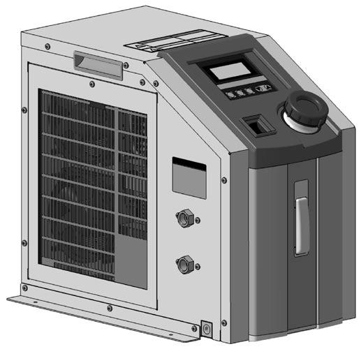
10 -A Series Parts Description 2 Power connector Handle Communication connector RS-232C type 1 pc. RS-485 type 2 pcs. Handle Display/Operation panel Power switch Alarm connector External temperature sensor connector Circulating fluid outlet Filter Tank lid with gasket level gauge Circulating fluid inlet Drain (circulating fluid drain port) 6 Power connector Handle Communication connector RS-232C type 1 pc. RS-485 type 2 pcs. Handle Display/Operation panel Power switch Alarm connector External temperature sensor connector Circulating fluid outlet Filter Tank lid with gasket level gauge Circulating fluid inlet Drain (circulating fluid drain port) 319
11 Peltier-Type Chiller Thermo-con (Air-cooled) -A Series Dimensions HRS R Power cable (Accessory) 4 x 5 Warning/Caution label Handle Model no. label Display/Operation panel 6 Power switch Tank lid with gasket Alarm output connector Communication connector Power connector Handle External temperature sensor connector HRSH9 HRS1/ Air Air Air Air level gauge x Plastic foot HRS9 49 Circulating fluid outlet Rc1/ HRSE HRSH Foot (Accessory) drain port (with plug) Rc1/4 HRZ Filter cover Filter inlet Rc1/4 HRZD Option (Fitting part) Power Cable (Accessory) NPT fitting specification (-N, -FN) outlet NPT1/4 inlet NPT1/4 drain port (with plug) NPT1/4 Connector: IEC 632 C13 or equivalent Cable: 14AWG, O.D. ø8.4 Wire color Contents Black 1 to 24 VAC Black 1 to 24 VAC Green/Yellow PE 2 Technical HED HEB R HRW 32
12 -A Series Dimensions R4 Warning/Caution label Display/Operation panel Power switch Handle Power connector Power cable (Accessory) Model no. label Handle 6 48 Tank lid with gasket Circulating fluid outlet Rc3/8 Air Circulating fluid inlet Rc3/8 278 Air Communication connector Alarm output connector External temperature sensor connector Air Air Foot (Accessory) Filter cover Filter drain port (with plug) Rc1/4 level gauge x x Plastic foot Option (Fitting part) NPT fitting specification (-N, -FN) outlet NPT3/8 inlet NPT3/8 drain port (with plug) NPT1/4 Power Cable (Accessory) Connector: IEC 632 C13 or equivalent Cable: 14AWG, O.D. ø8.4 Wire color Contents Black 1 to 24 VAC Black 1 to 24 VAC Green/Yellow PE 2 321
13 Peltier-Type Chiller Thermo-con (Air-cooled) -A Series Connectors 1. Power connector (AC) IEC 632 C14 or equivalent 1 2 Pin No. Contents to 24 VAC 1 to 24 VAC PE 3 HRS 2. Communication connector (RS-232C or RS-485) D-sub 9 pin (socket) Holding screw: M2.6 HRS9 Pin No Signal contents RS-232C RS-485 Unused BUS+ RD BUS SD Unused Unused Unused SG SG Unused Unused HRS1/15 HRSH9 3. External sensor connector (EXT.SENSOR) D-sub 15 pin (socket) Holding screw: M2.6 Pin No Signal contents Unused Terminal A of resistance temperature detector Terminal B of resistance temperature detector Terminal B of resistance temperature detector Unused FG HRSH Alarm output connector (ALARM) D-sub 9 pin (pin) Holding screw: M2.6 Pin No Signal contents Contact a for output cut-off alarm (open when alarm occurs) Common for output cut-off alarm Contact b for output cut-off alarm (closed when alarm occurs) Unused Contact a for upper/lower temp. limit alarm (open when alarm occurs) Common for upper/lower temp. limit alarm Contact b for upper/lower temp. limit alarm (closed when alarm occurs) Unused Technical HED HEB HRSE HRZ HRZD HRW R 322
14 -A Series Alarm This unit is equipped as standard with a function allowing 15 kinds of alarms to display on the LCD and can be read out by serial communication. Also, it can generate relay output for upper/lower temperature limit alarm and output cut-off alarm. Alarm Alarm code WRN ERR ERR1 ERR3 ERR4 ERR11 ERR12 Alarm description Upper/Lower temp. limit alarm CPU hung-up CPU check error Back-up data error EEPROM writing error DC power supply failure Internal temp. sensor high temp. error Operation status Continue Main reason The temperature has exceeded the upper or lower limit of the target temperature. The CPU has crashed due to noise, etc. The contents of the CPU cannot be read out correctly when the power supply is turned on. The contents of the back-up data cannot be read out correctly when the power supply is turned on. The data cannot be written to EEPROM. The DC power supply has failed (due to fan stop or abnormal high temperature) or the thermo-module has been short-circuited. The internal temperature sensor has exceeded the upper limit of cut-off temperature. Internal temp. sensor ERR13 low temp. error The internal temperature sensor has exceeded the lower limit of cut-off temperature. ERR14 Thermostat alarm The thermostat has been activated due to filter clog or fan/pump failure, etc. ERR15 Abnormal output alarm Continue The temperature cannot be changed even at 1% output due to overload or disconnection of the thermo-module. ERR16 Low flow rate alarm (option) The flow rate of the circulating fluid has dropped. ERR17 Internal temp. sensor disconnection alarm The internal temperature sensor has been disconnected or short-circuited. ERR18 External temp. sensor The external temperature sensor has been disconnected or short-circuited. (Only detected Continue disconnection alarm when in learning control or external tune control) ERR19 ERR2 Abnormal auto tuning alarm Low fluid level alarm Auto tuning has not been completed within 2 minutes. The amount of circulating fluid in the tank has dropped. Maintenance Maintenance of this unit is performed only in the form of return to and repair at SMC s site. As a rule, SMC will not conduct on-site maintenance. Separately, the following parts have a limited life and need to be replaced before the life ends. Parts Life Expectation Description Pump Fan DC power supply Expected life 3 to 5 years 5 to 1 years 5 to 1 years Possible failure The bearing is worn so the pump fails to transfer the circulating fluid, which results in temperature control failure. The bearing uses up lubrication and makes the fan unable to supply enough air, which deteriorates the cooling and heating capacity. The capacity of the electrolytic condenser decreases, and causes abnormal voltage which results in DC power supply failure and stops the thermo-con. Display panel 5, hours (approx. 5 years) The display turns off when the backlight of the LCD reaches the end of its life. 323
15 -A Series Options Options have to be selected when ordering the thermo-con. It is not possible to add them after purchasing the unit. F Option symbol With Flow Switch F HRS With flow switch This is an ON/OFF switch detecting low levels of the circulating fluid. When the fluid volume is 1 L/min. or less, ERR16 is displayed and the thermo-con stops. This switch is installed between the circulating fluid inlet and the tank, and built into the thermo-con. Refer to page 312. Type Applicable model 2-A5-F 6-A5-F N Option symbol NPT Thread N NPT thread The connection parts of circulating fluid piping, facility water piping and circulating fluid drain port are NPT thread type. Aircooled Type Aircooled Applicable model 2-A5-N 6-A5-N Technical HED HEB R HRS9 HRS1/15 HRSH9 HRSH HRSE HRW HRZD HRZ 324
16 -A Series Specific Product Precautions 1 Be sure to read this before handling the products. Refer to page 383 for safety instructions and pages 384 to 387 for temperature control equipment precautions. Warning Design 1. This catalog shows the specifications of the Thermo-con. 1. Check detailed specifications in the separate Product Specifications, and evaluate the compatibility of the thermo-con with user s system. 2. Although the protection circuit as a single unit is installed, the user is requested to carry out the safety design for the whole system. Warning Handling 1. Thoroughly read the Operation Manual. Read the Operation Manual completely before operation, and keep this manual available whenever necessary. 2. If the set temperature is repeatedly changed by 1 C or more, the thermo-con may fail in short periods of time. Caution Intake 1 mm or more Radiation Air 1. The inlet for radiation air must not be exposed to particles and dust as far as possible. 2. Do not let the inlet and outlet for radiation air get closed. <2> If radiation is prevented, the set temperature may not be achieved depending on the value of the set temperature and the load. Keep a space of 1 mm for opened rear side or 2 mm for closed rear side respectively. Discharge 1 mm or more The rear side is opened. Operating Environment/Storage Environment Warning 1. Keep within the specified ambient temperature and humidity range. Also, if the set temperature is too low, condensation may form on the inside of the thermo-con or the surface of piping even within the specified ambient temperature range. Dew condensation can cause failure, and so must be avoided by considering operating conditions. 2. The thermo-con is not designed for clean room usage. It generates dust from the pump inside the unit and the cooling fan. 3. Low molecular siloxane can damage the contact of the relay. Use the thermo-con in a place free from low molecular siloxane. <6> Intake 2 mm or more Intake 5 mm or more Discharge 2 mm or more Discharge 5 mm or more The rear side is closed. The rear side is opened. Intake Discharge The rear side is closed. 5 mm or more 5 mm or more The space must be 5 mm or more. Be sure that the ambient temperature is within the specification range. 325
17 -A Series Specific Product Precautions 2 Be sure to read this before handling the products. Refer to page 383 for safety instructions and pages 384 to 387 for temperature control equipment precautions. Caution Radiation Air Caution 3. If more than one thermo-con is used, consider their arrangement so that the downstream sides of the thermo-cons suck radiation air from the upstream sides. Otherwise, the performance at the downstream sides may deteriorate. Also, the set temperature may not be achieved depending on the value of the set temperature and the load. In such a case, take countermeasures such as changing the direction of the thermo-cons to prevent the deterioration of performance. 4. If dust adheres to the filter, remove dust with a vacuum cleaner or a dry cloth. 5. Do not operate without the filter. Otherwise, dust may accumulate on the heat sink and electrical components, causing abnormal heating. Circulating Fluid 1. Use tap water or fluid which will not damage the wetted material. (Stainless steel 33, Stainless steel 34, EPDM, Polypropylene, PE, PPE, Ceramics, Polyurethane) 2. Deionized water (with an electric conductivity of approx. 1 µs/cm) can be used, but may lose its electric conductivity. Also, if a facility supplying deionized water is used, the thermocon may be damaged by static electricity. 3. If deionized water is used, bacteria and algae may grow in short periods of time. If the thermo-con is operated with bacteria and algae, its cooling capacity or the capacity of the pump may deteriorate. Exchange all deionized water regularly depending on the conditions (once a month as a guide). 4. If using a fluid other than water, please contact SMC beforehand. 5. The maximum operating pressure of circulating fluid circuit is.1 MPa. If this pressure is exceeded, leakage from the tank in the thermo-con can result. 6. Select a pipe with a length and diameter which allow a flow rate of 1 L/min or more (2) or 3 L/min or more (6) for the circulating fluid. If the flow rate is less than these values, the thermo-con cannot provide precise control, but also can fail because of the repeated cooling and heating operation. 7. A magnet driven pump is used as a circulating pump. A fluid which contains metal powders such as iron powder cannot be used. 8. The thermo-con must not be operated without circulating fluid. The pump can break due to idling. Caution Circulating Fluid 9. If the tank lid is opened after the supply of circulating fluid, the circulating fluid may spill out depending on the condition of external piping. 1. If an external tank is used, the circulating fluid may spill out from the internal tank lid depending on where the external tank is installed. Check that the internal tank has no leakage if using an external tank. 11. If there is a point where fluid is released to atmosphere externally (tank or piping), minimize the piping resistance at the circulating fluid return side. If the piping resistance is too large, the piping may be crushed, or the built-in circulator tank may be deformed or cracked because the pressure in the piping for return will become negative. The built-in circulator tank is made of resin (PE). Therefore, the tank may be crushed if the pressure is negative. Special attention must be paid if the flow rate of the circulating fluid is high. To avoid a negative pressure of.2 MPa or below, the piping for return should be as thick and short as possible to minimize the piping resistance. It is also effective to restrict the flow rate of circulating fluid or remove the gasket of internal tank for the release to atmosphere. 12. Fluorinated fluid is outside of the specifications. If it is used in the thermo-con, static electricity will be generated by the flow of fluid. This static electricity may be discharged to the board of the thermo-con, causing damage or operation failure and loss of data of such as set temperature. Also, as the specific gravity of the fluorinated fluid is 1.5 to 1.8 times of water, the pump will be overloaded, which also causes fluorinated fluid to be outside the specifications. Therefore, if fluorinated fluid is used, please contact SMC and we will introduce a suitable special product (water-cooled type). 13. Avoid operation with cavitation or bubbles due to low fluid level in the tank. This may shorten the pump life. 14. If tap water is used, it should satisfy the quality standards shown below. Tap Water (as Circulating Water) Quality Standards The Japan Refrigeration and Air Conditioning Industry Association JRA GL Cooling water system Circulating type Supply water Influence Item Unit Standard value Scale Corrosion generation ph (at 25 C) Electric conductivity (25 C) Chloride ion (Cl ) Sulfuric acid ion (SO 2 4 ) Acid consumption amount (at ph4.8) Total hardness Calcium hardness (CaCO 3 ) Ionic state silica (SiO 2 ) Iron (Fe) Copper (Cu) Sulfide ion (S 2 ) Ammonium ion (NH 4+ ) Residual chlorine (Cl) Free carbon (CO 2 ) [µs/cm] [mg/l] [mg/l] [mg/l] [mg/l] [mg/l] [mg/l] [mg/l] [mg/l] [mg/l] [mg/l] [mg/l] [mg/l] 6. to to or less 5 or less 5 or less 7 or less 5 or less 3 or less.3 or less.1 or less Should not be detected..1 or less.3 or less 4. or less 1 In the case of [MΩ cm], it will be.3 to.1. : Factors that have an effect on corrosion or scale generation. Even if the water quality standards are met, complete prevention of corrosion is not guaranteed. Standard item Reference item 326 HRS HRS9 HRS1/15 HRSH9 HRSH HRSE HRZ HRZD HRW R HED HEB Technical
18 -A Series Specific Product Precautions 3 Be sure to read this before handling the products. Refer to page 383 for safety instructions and pages 384 to 387 for temperature control equipment precautions. Caution 1. The set value can be written to EEPROM, but only up to approx. 1 million times. In particular, pay attention to how many of times the writing is performed using the communication function. Warning Communication Maintenance 1. Prevention of electric shock and fire Do not operate the switch with wet hands. Also, do not operate the thermo-con with water left on it. 2. Action in the case of error If any error such as abnormal sounds, smoke, or bad smell occurs, cut off the power at once, and stop supplying and conveying fluid. Please contact SMC or a sales distributor to repair the thermo-con. 3. Regular inspection Check the following items at least once a month. The inspection must be done by an operator who has sufficient knowledge and experience. a) Check of displayed contents. b) Check of temperature, vibration and abnormal sounds in the body of the thermo-con. c) Check of the voltage and current of the power supply system. d) Check for leakage and contamination of the circulating fluid and intrusion of foreign matter to it, and subsequent replacement of the fluid. e) Check for flow condition, temperature and filter of radiation air. 327
19 Technical HED HEB R HRW HRZD HRZ HRSE HRSH HRSH9 HRS1/15 HRS9 HRS 328
20 Peltier-Type Chiller Thermo-con (Water-cooled) -W Series Note) Except 6, 12 RoHS 14 W, 32 W How to Order 3 W 5 B Cooling capacity 1 14 W 3 32 W Radiating method W Water-cooled Power supply 5 1 to 24 VAC Option Nil None F With flow switch N NPT thread L With level switch The option should be specified when ordering. Communication A RS-485 B RS-232C Select B when communication is not used. Specifications (For details, please refer to our Product Specifications information.) Model 1-W5A 1-W5B 3-W5A 3-W5B Cooling method Radiating method Control method Ambient temperature/humidity Operating temp. range Thermoelectric device (Thermo-module) Water-cooled Cooling/Heating automatic shift PID control 1 to 35 C, 35 to 8%RH (no condensation) Tap water, 2% ethylene glycol 1. to 6. C (no condensation) Cooling capacity Heating capacity 14 W 1 4 W 1 32 W 1 77 W 1 Temperature stability 2 Pump capacity Tank capacity Port size Fluid contact material Temperature range Pressure range Required flow rate 3 Port size Fluid contact material Power supply Overcurrent protector ±.1 to.3 C Refer to performance chart. Approx. 1.2 L IN/OUT: Rc3/8 Drain: Rc1/4 (with plug) PPE, PP glass 1%, Alumina ceramics, Carbon, EPDM, Stainless steel 33, Stainless steel 34, PE, PP, NBR 1 to 35 C (no condensation) Within 1 MPa 3 to 7 L/min IN/OUT: Rc3/8 Stainless steel 34 Single-phase 1 to 24 VAC ±1%, 5/6 Hz 1 A Current consumption 3.5 A (1 VAC) to 1.5 A (24 VAC) 5.5 A (1 VAC) to 2.5 A (24 VAC) Alarm Communications RS-485 Refer to alarm function. RS-232C RS-485 RS-232C Weight Approx. 12 kg Approx. 13 kg Accessories Safety standards Power cable, Foot for fixing, Splashproof cover CE marking, UL (NRTL) standards, SEMI 1 /Tap water conditions: set temperature 2 C, Flow rate 5 L/min., Facility water temperature 2 C, Flow rate 5 L/min., Ambient temperature 25 C 2 The indicated values are with a stable load without turbulence in the operating conditions. It may be out of this range in some other operating conditions. 3 The flow rate beyond the proper range may deteriorate performance or generate noise, causing the piping to break. system Facility water system Electrical system 329

 Model 6-W2A 6-W2B 12-W2A 12-W2B Cooling method Radiating method Control method Ambient temperature/humidity 1 Operating temperature range Thermoelectric device (Thermo-module) Water-cooled")
21 Peltier-Type Chiller Thermo-con (Water-cooled) -W Series 6 W, 12 W How to Order 12 W 2 B Cooling capacity 6 6 W W HRS Radiating method W Water-cooled Power supply 2 2 to 22 VAC Option Nil None N NPT thread The option should be specified when ordering. Communication A RS-485 B RS-232C Select B when communication is not used. HRS9 HRS1/15 HRSH9 Specifications (For details, please refer to our Product Specifications information.) Model 6-W2A 6-W2B 12-W2A 12-W2B Cooling method Radiating method Control method Ambient temperature/humidity 1 Operating temperature range Thermoelectric device (Thermo-module) Water-cooled Cooling/Heating automatic shift PID control 1 to 35 C, 35 to 8%RH (no condensation) Tap water, Fluorinated fluid (Fluorinert FC-3283, GALDEN HT135) 1. to 6. C (no condensation) Cooling capacity Heating capacity 6 W (Tap water), 4 W (Fluorinert FC-3283) 2 9 W (Tap water), 6 W (Fluorinert FC-3283) 2 12 W (Tap water), 8 W (Fluorinert FC-3283) 3 22 W (Tap water), 15 W (Fluorinert FC-3283) 3 Temperature stability 4 Pump capacity ±.1 to.3 C Refer to performance chart. Tank capacity Approx. 3 L Approx. 5 L system Port size Fluid contact material IN/OUT: Rc3/8 Drain: Rc1/4 (with plug) Stainless steel 33, Stainless steel 34, EPDM, Ceramics, PPS glass 3%, Carbon, PE, Polyurethane IN/OUT: Rc3/4 Drain: Rc1/4 (with plug) Stainless steel 33, Stainless steel 34, EPDM, Ceramics, PP, PE, Polyurethane, SiC, PPS Temperature range 1 to 35 C (no condensation) Pressure range Within 1 MPa Required flow rate 5 8 to 15 L/min 1 to 15 L/min Port size IN/OUT: Rc3/8 IN/OUT: Rc1/2 Fluid contact material Stainless steel 33, Stainless steel 34 Power supply Single-phase 2 to 22 VAC ±1%, 5/6 Hz Overcurrent protector 1 A 15 A Current consumption 5 A 1 A Alarm Refer to alarm function. Communications RS-485 RS-232C RS-485 RS-232C Weight Approx. 25 kg (including foot for fixing) Approx. 4 kg (including foot for fixing) Accessories Power cable, Foot for fixing Safety standards CE marking 1 GALDEN is a registered trademark, belonging to the Solvay Group or its corresponding owner. Fluorinert is a trademark of 3M. Regarding the fluid other than the above, please consult with SMC. 2 Conditions: Set temperature 25 C, Facility water temperature 2 C, Facility water flow rate 8 L/min, Ambient temperature 25 C. 3 Conditions: Set temperature 25 C, Facility water temperature 2 C, Facility water flow rate 1 L/min, Ambient temperature 25 C. 4 The indicated values are with a stable load without turbulence in the operating conditions. It may be out of this range in some other operating conditions. 5 The flow rate beyond the proper range may deteriorate performance or generate noise, causing the piping to break. Facility water system Electrical system HRSH HRSE HRZ HRZD HRW R HED HEB Technical 33 A
22 -W Series Cooling Capacity The values shown on the performance chart are not guaranteed, but typical. Allow margins for safety when selecting the model. 1 : Tap water : 2% ethylene glycol 6 6 Cooling capacity [W] C Facility water: 2 C 3 C 1 Facility water flow rate: 5 L/min Cooling capacity [W] C 2 1 Facility water flow rate: 5 L/min temperature [ C] temperature [ C] 3 : Tap water : 2% ethylene glycol 1 1 Cooling capacity [W] C Facility water: 2 C 3 C Cooling capacity [W] C Facility water flow rate: 5 L/min temperature [ C] Facility water flow rate: 5 L/min temperature [ C] 6 : Tap water : FC Cooling capacity [W] C Facility water: 2 C 35 C Cooling capacity [W] C Facility water: 2 C 35 C Facility water flow rate: 8 L/min temperature [ C] Facility water flow rate: 8 L/min temperature [ C] 12 : Tap water : FC-3283 Cooling capacity [W] C Facility water: 2 C 35 C Cooling capacity [W] C Facility water: 2 C 35 C Facility water flow rate: 1 L/min Facility water flow rate: 1 L/min temperature [ C] temperature [ C] 331
23 Peltier-Type Chiller Thermo-con (Water-cooled) -W Series Heating Capacity 1 Heating capacity [W] Heating capacity [W] 1 temperature [ C] : Tap water Facility water flow rate: 5 L/min 3 C 2 C 1 C : Tap water Facility water flow rate: 5 L/min 3 C 2 C 1 C temperature [ C] Heating capacity [W] Heating capacity [W] The values shown on the performance chart are not guaranteed, but typical. Allow margins for safety when selecting the model : 2% ethylene glycol Facility water flow rate: 5 L/min temperature [ C] 2 C : 2% ethylene glycol Facility water flow rate: 5 L/min temperature [ C] 2 C HRSE HRSH HRSH9 HRS1/15 HRS9 HRS 6 : Tap water : FC-3283 HRZ 15 Facility water flow rate: 8 L/min 15 Facility water flow rate: 8 L/min Heating capacity [W] 1 5 temperature [ C] 35 C 2 C 1 C Heating capacity [W] C 1 C temperature [ C] 35 C HRZD HRW R 12 : Tap water : FC-3283 Heating capacity [W] Facility water flow rate: 1 L/min 1 C temperature [ C] 35 C 2 C Heating capacity [W] Facility water flow rate: 1 L/min 1 C temperature [ C] 35 C 2 C HED HEB Technical 332
24 -W Series Pump Capacity (Thermo-con Outlet) 1/3 Since a DC pump is used, the unit is not affected by power requirements..15 Discharge pressure [MPa].1.5 2% ethylene glycol Tap water flow rate [L/min] 6 Since a DC pump is used, the unit is not affected by power requirements Discharge pressure [MPa].1.5 Tap water Fluorinert FC-3283 Discharge pressure [MPa] Hz Fluorinert FC Hz Tap water 6 Hz Hz flow rate [L/min] flow rate [L/min] Pressure Loss in Facility Water Circuit Pressure loss [MPa] Pressure loss [MPa] Facility water flow rate [L/min] Facility water flow rate [L/min] 12.6 Pressure loss [MPa] Pressure loss [MPa] Facility water flow rate [L/min] Facility water flow rate [L/min] 333
 Facility water outlet Facility water inlet HRS Handle inlet External temperature sensor")


25 Peltier-Type Chiller Thermo-con (Water-cooled) -W Series Parts Description 1/3 Display/Operation panel Tank lid (with O-ring) Facility water outlet Facility water inlet HRS Handle inlet External temperature sensor connector Alarm output connector HRS9 Power switch level gauge outlet Drain ( drain port) Communication connector RS-232C type 1 pc. RS-485 type 2 pcs. Power connector (Connect the attached power cable.) Splashproof cover HRS1/15 HRSH9 6/12 Display/Operation panel Tank lid (with gasket) level gauge Handle Facility water outlet Facility water inlet Splashproof cover Cooling fan Communication connector RS-232C type 1 pc. RS-485 type 2 pcs. Alarm output connector External temperature sensor connector Power connector (Connect the attached power cable.) Power switch outlet inlet Drain ( drain port) Technical HED HEB HRSE HRZ HRZD HRW R HRSH 334
26 -W Series Dimensions 1-W5 3-W5 Warning/Caution label 182 (32) 12 (55) Tank lid (with O-ring) (45.5) Foot (Accessory) 4 x width 5 Display/ Operation panel Power switch (25) (19) 184 ø72 Power Cable (Accessory) level gauge Handle 1 27 (13) Splashproof cover (Accessory) Circulating fluid inlet Rc3/ DRAIN IN OUT IN RADIATING WATER RECIRCULATING WATER OUT 148 EXT.SENSOR ALARM RS-232C 28 Model no. label drain port Rc1/4 (With plug) AC Facility water outlet Rc3/8 Facility water inlet Rc3/8 outlet Rc3/8 External temperature sensor connector Alarm output connector Communication connector Power connector For NPT thread specification (-N), all fittings (including those at the circulating fluid drain port) are made of NPT. Connector: IEC 632 C13 or equivalent Cable: 14AWG, O.D. ø8.4 Wire color Contents Black 1 to 24 VAC Black 1 to 24 VAC Green/Yellow PE 2 Power cable (Accessory) 335
27 Peltier-Type Chiller Thermo-con (Water-cooled) -W Series Dimensions 6-W2 Foot (Accessory) Power switch HRS (13) 4 x Display/ Operation panel Foot (Accessory) Warning/Caution label HRSH HRS9 HRS1/15 HRSH9 H L level gauge Tank lid with gasket Handle 4 Air Facility water outlet Rc3/8 Circulating fluid outlet Rc3/8 Circulating fluid inlet Rc3/8 Model no. label OUT IN RADIATING WATER OUT RECIRCULATING FLUID IN DRAIN Facility water inlet Rc3/8 5 RS-232C ALARM EXT.SENSOR AC Fan 8 Communication connector 33 Alarm output connector External temperature sensor connector Power connector HRW HRZD HRZ HRSE 482 drain port Rc1/4 (with plug) R For NPT thread specification (-N), all fittings (including those at the circulating fluid drain port) are made of NPT. Power Cable Connector: IEC 632 C13 or equivalent Cable: 14AWG, O.D. ø8.4 Wire color Contents Black 2 to 22 VAC Black 2 to 22 VAC Green/Yellow PE 2 Power cable (Accessory) Technical HED HEB 336
28 -W Series Dimensions 12-W2 Foot (Accessory) Power switch (55) 4 x Display/ Operation panel Foot (Accessory) Warning/Caution label level gauge Tank lid with gasket Handle 4 Facility water outlet Rc1/ outlet Rc3/4 5 H L Air Facility water inlet Rc1/ DRAIN OUT RADIATING WATER IN OUT RECIRCULATING FLUID IN RS-232C ALARM EXT.SENSOR AC Fan Communication connector Alarm output connector External temperature sensor connector Power connector 55 drain port Rc1/4 (with plug) 277 Model no. label inlet Rc3/4 For NPT fitting specification (-N), all fittings (including those at the circulating fluid drain port) are made of NPT. Power Cable Connector: DDK CE5-6A18-1SD-D-BSS or equivalent Cable: 14AWG, O.D. ø8.4 Wire color Black Black Green/Yellow Contents 2 to 22 VAC 2 to 22 VAC PE 2 Power cable (Accessory) 337
29 Peltier-Type Chiller Thermo-con (Water-cooled) -W Series Connectors 6-W2/1-W5/3-W5 1. Power connector (AC) IEC 632 C14 or equivalent 6-W2 Pin No Pin No Contents 2 to 22 VAC 2 to 22 VAC PE RS-232C Unused RD SD Unused SG Unused Signal contents RS-485 BUS+ BUS Unused Unused SG Unused 1-W5 3-W5 Pin No Contents 1 to 24 VAC 1 to 24 VAC PE 2. Communication connector (RS-232C or RS-485) D-sub 9 pin (socket) Holding screw: M HRSH HRSH9 HRS1/15 HRS9 HRS 3. External sensor connector (EXT.SENSOR) D-sub 15 pin (socket) Holding screw: M2.6 Pin No Signal contents Unused Terminal A of resistance temperature detector Terminal B of resistance temperature detector Terminal B of resistance temperature detector Unused FG 4. Alarm output connector (ALARM) D-sub 9 pin (pin) Holding screw: M2.6 Pin No Signal contents Contact a for output cut-off alarm (open when alarm occurs) 3 4 Common for output cut-off alarm Contact b for output cut-off alarm (closed when alarm occurs) Unused Contact a for upper/lower temp. limit alarm (open when alarm occurs) Common for upper/lower temp. limit alarm Contact b for upper/lower temp. limit alarm (closed when alarm occurs) Unused R HRW HRZD HRZ HRSE 12-W2 Power connector (AC) DDK CE5-2A18-1PD-D or equivalent Pin No. A B C D Contents 2 to 22 VAC 2 to 22 VAC Unused PE Other connectors are the same as those for the 6-W2. D C A B HED HEB Technical 338
30 -W Series Alarm This unit is equipped as standard with a function allowing 16 kinds of alarms to display on the LCD and can be read out by serial communication. Also, it can generate relay output for upper/lower temperature limit alarm and output cut-off alarm. Alarm code WRN ERR ERR1 ERR3 ERR4 ERR5 ERR11 ERR12 ERR13 ERR14 ERR15 ERR16 ERR17 ERR18 ERR19 ERR2 Alarm description Upper/Lower temp. limit alarm CPU hung-up CPU check error Back-up data error EEPROM writing error EEPROM input over time error 4 DC power supply failure Internal temp. sensor high temp. error Internal temp. sensor low temp. error Thermostat alarm Abnormal output alarm Pump failure 1 or low circulating fluid level alarm 2 Internal temp. sensor disconnection alarm External temp. sensor disconnection alarm Abnormal auto tuning alarm Low fluid level alarm 3 Operation status Continue Continue 1 The 12 only 2 Optional for the 1 and 3 only (Not available for the 6) 3 Optional for the 1 and 3 4 The 1 and 3 only Main reason The temperature has exceeded the upper or lower limit of the target temperature. The CPU has crashed due to noise, etc. The contents of the CPU cannot be read out correctly when the power supply is turned on. The contents of the back-up data cannot be read out correctly when the power supply is turned on. The data cannot be written to EEPROM. The number of times of writing to EEPROM has exceeded 1 million times. The DC power supply has failed (due to abnormal high temperature) or an irregular voltage has occurred or the thermo-module has been short-circuited. The internal temperature sensor has exceeded the upper limit of cut-off temperature. The internal temperature sensor has exceeded the lower limit of cut-off temperature. The thermostat has been activated due to insufficient of the facility water or high temperature. Continue The temperature cannot be changed even at 1% output due to overload or disconnection of the thermo-module. The pump has been overloaded 1 or the flow switch is activated 2. The internal temperature sensor has been disconnected or short-circuited. The external temperature sensor has been disconnected or short-circuited. (Only detected when in learning control or external tune control.) Auto tuning has not been completed within 2 minutes. The amount of circulating fluid in the tank has dropped and the level switch is activated. Maintenance Maintenance of this unit is performed only in the form of return to and repair at SMC s site. As a rule, SMC will not conduct on-site maintenance. Separately, the following parts have a limited life and need to be replaced before the life ends. Parts Life Expectation Description Pump Fan DC power supply Display panel Expected life Possible failure 3 to 5 years The bearing is worn so the pump fails to transfer the circulating fluid, which results in temperature control failure. The bearing uses up lubrication and makes the fan unable to supply enough air, which increases the internal temperature of the thermo-con, and activates the overheat protection of the power supply and generates the alarm. 5 to 1 years The capacity of the electrolytic condenser decreases, and causes abnormal voltage which results in DC power supply 5 to 1 years failure and stops the thermo-con. 5, hours The display turns off when the backlight of the LCD reaches the end of its life. (approx. 5 years) 339
31 -W Series Options Options have to be selected when ordering the thermo-con. It is not possible to add them after purchasing the unit. F Option symbol With Flow Switch F HRS With flow switch This is an ON/OFF switch detecting low levels of the circulating fluid. When the fluid volume is 1 L/min. or less, ERR16 is displayed and the thermo-con stops. This switch is installed between the circulating fluid inlet and the tank, and built into the Thermo-con. Refer to page 312. Type Applicable model 1-W5-F 3-W5-F HRS9 HRS1/15 N Option symbol NPT Thread HRSH9 N NPT thread The connection parts of circulating fluid piping, facility water piping and circulating fluid drain port are NPT thread type. Type Applicable model 1-W5-N 3-W5-N 6-W2-N 12-W2-N L Option symbol With Level Switch L With level switch This switch is used to detect a LOW level of tank fluid. When the fluid level becomes below the LOW level, ERR2 is displayed and the thermo-con stops. This switch is installed in the circulating fluid tank and built into the thermo-con. Refer to page 312. Type Watercooled Watercooled Watercooled Applicable model 1-W5-L 3-W5-L Other models include a level switch as standard equipment. Technical HED HEB HRSH HRSE HRZD HRW R HRZ 34
32 -W Series Specific Product Precautions 1 Be sure to read this before handling the products. Refer to page 383 for safety instructions and pages 384 to 387 for temperature control equipment precautions. Warning 1. This catalog shows the specifications of the thermo-con. 1. Check detailed specifications in the separate Product Specifications, and evaluate the compatibility of the thermo-con with user s system. 2. Although the protection circuit as a single unit is installed, the user is requested to carry out the safety design for the whole system. Warning Design Operating Environment/Storage Environment Warning Handling 1. Thoroughly read the Operation Manual. Read the Operation Manual completely before operation, and keep this manual available whenever necessary. 2. If the set temperature is repeatedly changed by 1 C or more, the thermo-con may fail in short periods of time. 1. Keep within the specified ambient temperature and humidity range. Also, if the set temperature is too low, condensation may form on the inside of the thermo-con or the surface of piping even within the specified ambient temperature range. Dew condensation can cause failure, and so must be avoided by considering operating conditions. 2. The thermo-con is not designed for clean room usage. The pump and fan generate dust. 3. Low molecular siloxane can damage the contact of the relay. Use the thermo-con in a place free from low molecular siloxane. 341 Operating Environment/Storage Environment Warning 4. Installation conditions If the space for the intake and discharge of air is insufficient, the amount of transferred air will decrease, which can impair the performance and life of the product. Therefore, keep the conditions illustrated below for installation. Also, if ambient temperature is expected to be over 35 C, vent or exhaust air to prevent the increase of ambient temperature over 35 C. <6/12> Intake 1 mm or more Discharge Leave space 15 mm or more Intake 1 mm or more Leave space 1 mm or Intake more <1/3> It is not necessary to leave space for ventilation. Install the product while taking working space for installation and maintenance into account. However, ventilation must be also considered so that ambient temperature does not excessively rise. Caution Caution Facility Water 1. If the temperature of the facility water is too low, it can cause formation of dew condensation inside the heat exchanger. Supply facility water with a temperature over the atmospheric dew point to avoid the formation of dew condensation. 2. If the facility water piping is connected to multiple machines, the facility water exchanges heat at the upstream side and its temperature will become higher as it goes downstream. Limit the number of connected thermo-cons to two per facility water system, and if more than two thermo-cons are to be connected, increase the number of systems. Circulating Fluid 1. Use tap water or fluid which will not damage the wetted parts material as described in this catalog s specifications. (PPE, PP glass 1%, Alumina ceramics, Carbon, EPDM, Stainless steel 33, Stainless steel 34, PE, PP, NBR) 2. Deionized water (with an electric conductivity of approx. 1 µs/cm) can be used, but may lose its electric conductivity.
Added cooling capacity of 140 W. (air-cooled).
.") Peltier-Type Chiller/Thermo-con Series Air-cooled Water-cooled Can precisely control the temperature of a heat source or process fluid. Precisely control the temperature of the circulating fluid by using
Peltier-Type Chiller/Thermo-con Series Air-cooled Water-cooled Can precisely control the temperature of a heat source or process fluid. Precisely control the temperature of the circulating fluid by using
Added cooling capacity of 140 W. (air-cooled).
.") Peltier-Type Chiller Thermo-con Can precisely control the temperature of a heat source or process fluid. Precisely control the temperature of the circulating fluid by using the Peltier device. Generates
Peltier-Type Chiller Thermo-con Can precisely control the temperature of a heat source or process fluid. Precisely control the temperature of the circulating fluid by using the Peltier device. Generates
Added cooling capacity of 140 W and 320 W (watercooled), (air-cooled). Thermo-con. controlled to a constant temperature
, (air-cooled). Thermo-con. controlled to a constant temperature") Peltier-Type Chiller Thermo-con Air-cooled Water-cooled Series Can precisely control the temperature of a heat source or process fluid. Precisely control the temperature of the circulating fluid by using
Peltier-Type Chiller Thermo-con Air-cooled Water-cooled Series Can precisely control the temperature of a heat source or process fluid. Precisely control the temperature of the circulating fluid by using
HEB Series. Peltier-Type Thermoelectric Bath
 Peltier-Type Thermoelectric Bath HRS090 HRZD HRZ HRSE HRSH Environmentally friendly and refrigerant-free Heaterless Function to detect abnormal heating and temperature sensor errors comes standard. Light
Mountable in a 19-inch rack
 Peltier-Type Chiller/Thermo-con HECR Series Air-cooled Rack Mount Type (UL Standards) RoHS HRS Good space utilization Mountable in a 19-inch rack Saves space by mounting multiple equipment together in
HEB Series. Thermoelectric Bath
 Peltier-Type Thermoelectric Bath HEB Series Accurately controls the temperature of liquid in the bath. Temperature stability: ±0.01 C Temperature distribution: ±0.02 C in the bath RoHS 100/150 Environmentally
Thermoelectric Bath. Series HEB
 Peltier-Type Thermoelectric Bath Series HEB Accurately controls the temperature of liquid in the bath. Temperature stability: ±0.018 F Temperature distribution: ±0.036 F in the bath Environmentally friendly
Thermoelectric Bath. Series HEB
 Peltier-Type Thermoelectric Bath Accurately controls the temperature of liquid in the bath. Temperature stability: ±0.018 F Temperature distribution: ±0.036 F in the bath Environmentally friendly and refrigerant-free
Precisely control the temperature of the circulating fluid by using the Peltier device. Refrigerant-free and environmentally friendly.
 Peltier-type Chiller Thermo-con/Rack Mount Type Air-cooled Water-cooled The water-cooled type has been added. (8 W, 1.2 kw) Reduces the amount of exhaust heat by 9% Suppresses rises in the ambient temperature
10 c to 60 c 300 W, 500 W, 750 W. direct temperature control for chemical liquids!! HED Series. Industry-leading withstand pressure 0.35 MPa!!
 Peltier-Type Temperature Control System for Chemical Liquids Chemical Thermo-con Peltier device (Thermo-module) Fluororesin heat exchanger Type of circulating fluid Deionized water Hydrofluoric acid Ammonia
Chemical Thermo-con. How to Order. Communication A RS-485 B RS-232C. Power supply 2 Single-phase: 180 to 242 VAC 50/60 Hz.
 Chemical Thermo-con Series HED How to Order Part number of set (Temperature controller + Heat exchanger) Note) The name plate on the Chemical Thermo-con shows the model numbers of the controller and heat
Peltier-Type Temperature Control System for Chemicals. Fluororesin heat exchanger allows direct temperature control for chemicals!!
 Peltier-Type Temperature Control System for Chemicals Chemical Thermo-con Fluororesin heat exchanger allows direct temperature control for chemicals!! Temperature controller POWER THERMO-CON AT SEL RET
Water-cooled Thermo-chiller
 Circulating Fluid Temperature Controller Water-cooled Thermo-chiller Series Refrigerant-free and energy saving type using no compressor. Ideal for ordinary temperature and high temperature processes. Type
SEMI Standard S2-0703, S8-1103, F
 Circulating Fluid Temperature Controller Water-cooled Thermo-chiller Series Refrigerant-free and energy saving type using no compressor. Ideal for ordinary temperature and high temperature processes. Type
Refrigerated Thermo-chiller
 Circulating Fluid Temperature Controller Refrigerated Thermo-chiller Series Type of Fluorinated fluids/ethylene glycol aqueous solution/ circulating fluid: Clear water, Deionized water Temperature range
Type of Fluorinated fluids / Ethylene glycol aqueous solution / circulating fluid: Clear water, Deionized water Temperature range setting:
 Circulating Fluid Temperature Controller Refrigerated Thermo-chiller Series Type of Fluorinated fluids / Ethylene glycol aqueous solution / circulating fluid: Clear water, Deionized water Temperature range
Water-cooled Thermo-chiller
 SEMATECH S2-93, S8-95 temperature controller Water-cooled Thermo-chiller Refrigerant-free and energy saving type using no compressor. Ideal for ordinary temperature and high temperature processes. types:
Chiller Lineup. Thermo-chiller. A chiller is used to control the temperature of circulating fluid and supply it to the heat source.
 A chiller is used to control the temperature of circulating fluid and supply it to the heat source. Thermo-cooler Series HRG General-purpose, economy type for machine tools, etc. Cooling capacity: 1 kw
Circulating Fluid Temperature Controller Refrigerated Thermo-cooler
 Circulating Fluid Temperature Controller Refrigerated Thermo-cooler Makes cooling water easily available, anytime, anywhere. Worldwide in voltage: Single phase 200 to 230 VAC, 50/60 Hz Compliant with standards:,
Water-cooled Thermo-chiller
 Circulating Fluid Temperature Controller Water-cooled Thermo-chiller SEMATECH S2-93, S8-95 SEMI Standard S2-73, S8-113, F47-2 Series Refrigerant-free and energy saving type using no compressor. Ideal for
Water-cooled Thermo-chiller
 temperature controller Water-cooled Thermo-chiller Refrigerant-free and energy saving type using no compressor. Ideal for ordinary temperature and high temperature processes. Circulating Fluorinated fluids
A Chiller is equipment to control temperature of customers heating sources. Application Examples
 Control Equipment What s a Chiller? A Chiller is equipment to control temperature of customers heating sources. Chillers control, such as water, and circulate the to customers machine using a pump by controlling
Refrigerated Thermo-cooler
 Circulating Fluid Temperature Controller Refrigerated Thermo-cooler Series Makes cooling water easily available, anytime, anywhere. Cooling capacity (60 Hz): 9.5 kw/14.5 kw (Air-cooled refrigeration) 11.0
Large energy saving by triple control!
 Circulating Fluid Temperature Controller Thermo-chiller Basic Type (Only 23 VAC type) RoHS Large energy saving by triple control!.8 kw.54 kw Power consumption 33% Energy saving * Under the conditions shown
±0.1 C. 40 kg. 47 kg. 69 kg 73 kg. With heating function. Convenient functions
 Circulating Fluid Temperature Controller Thermo-chiller Lightweight/Compact Temperature stability Standard Type ±.1 C New HRS5 New HRS6 (UL Standards) RoHS HRS12/18/24 New HRS3 Same width for all models:
0.1 c. R134a (HFC) Thermo-chiller. ( A device for circulating a fluid ) Series HRZ. with a constant temperature
 Thermo-chiller. ( A device for circulating a fluid ) Series HRZ. with a constant temperature") Circulating fluids type: Fluorinated fluids, Ethylene glycol aqueous solution / Clean water, Pure water Temperature 2 to 4 c 2 to 9 c 2 setting range: to 9 c Cooling capacity: 1 kw 2 kw 4 kw 8 kw to Max.15
Circulating fluids type: Fluorinated fluids, Ethylene glycol aqueous solution / Clean water, Pure water Temperature 2 to 4 c 2 to 9 c 2 setting range: to 9 c Cooling capacity: 1 kw 2 kw 4 kw 8 kw to Max.15
Large energy saving by triple control!
 Circulating Fluid Temperature Controller Thermo-chiller E Series Basic Type Large energy saving by triple control!.8 kw Without triple control.54 kw Triple control Cooling capacity 1.2, 1.6, 2.2 kw Power
using heat exhausted by refrigerating circuit.
 Circulating Fluid Temperature Controller Thermo-chiller No heater required, circulating fluid is heated using heat exhausted by refrigerating circuit. Circulating fluid temperature [ F] Cooling capacity
Operation Manual. Thermo Electric Bath HEBC002-WA10 HEBC002-WB10
 A_HEC-OM-J004 Rev.3 May 2012 Operation Manual Thermo Electric Bath HEBC002-WA10 HEBC002-WB10 Copying, duplicating or transferring any part or the entirety of this manual without the prior permission of
RoHS HRG(C)005 (Existing model) (mm) 69 kg 5100 W
005 (Existing model) (mm) 69 kg 5100 W") New Circulating Fluid Temperature Controller Thermo-chiller (UL Standards) Compact Type RoHS HRG(C)5 (Existing model) Compact Space-saving HRS5 976 Ve 615 n tio 592 5 377 377 (mm) (mm) Lightweight 4 kg
New Circulating Fluid Temperature Controller Thermo-chiller (UL Standards) Compact Type RoHS HRG(C)5 (Existing model) Compact Space-saving HRS5 976 Ve 615 n tio 592 5 377 377 (mm) (mm) Lightweight 4 kg
Large energy saving by triple control!
 Circulating Fluid Temperature Controller Thermo-chiller Small Basic Type RoHS Large energy saving by triple control! Compressor Fan Valve Triple control.8 kw.54 kw Power consumption 33% Energy saving *
Refrigeration air dryer
 Principle of refrigeration air dryer Pneumatic circuit (System diagram) Warm wet water is precooled by compressed air chilled and dehumidified by air balancer (A) (precooler). Precooled compressed air
Technical Data C O N T E N T S
 C O N T E N T S A Accumulator Page 375 Adjustment sensitivity (Hysteresis) Page 379 Air-cooled condenser Page 374 Analog communication Page 381 ARW width (Anti-Reset Windup width) Page 379 Auto-tuning
Lightweight and Compact
 Circulating Fluid Temperature Controller Thermo-chiller Standard Type (Only 400 VAC type) Lightweight and Compact RoHS Cooling capacity 9 kw Weight 136 kg Temperature stability ±0.5 C (when a load is stable)
Recirculating Coolers
 09 Recirculating Coolers (chillers) General Recirculating Coolers Low Temp. Recirculating Coolers Advanced Low Temp. Recirculating Coolers High Temp. Recirculating Coolers Compact Recirculating Cooler
Refrigerated Air Dryer
 Refrigerated Air Dryer For Use in Southeast Asia Applicable for the high-temperature environments of tropical regions Can be used in high-temperature environments Ambient temperature : Max. 45 C Inlet
Customized Industrial Products
 Customized Industrial Products Product Catalog Large Walk-in Type Drying Oven Large Size Autoclave Large Size Fine Oven Targeting Productivity Improvement Yamato offers customization of products based
Air Filter. Filter for Removing Dust and Drain in Compressed Air. Filter for Drain and Dust (Filtering Accuracy: 5µm)
") http://www.pisco.co.jp AIR PREPARATION ACTUATOR PLARAILCHAIN HARMO ROBOT PARTS Filter for Removing Dust and Drain in Compressed Air Air Filter 220 Filter for Drain and Dust (Filtering Accuracy: 5µm) Resin-made
http://www.pisco.co.jp AIR PREPARATION ACTUATOR PLARAILCHAIN HARMO ROBOT PARTS Filter for Removing Dust and Drain in Compressed Air Air Filter 220 Filter for Drain and Dust (Filtering Accuracy: 5µm) Resin-made
VRA2000 Series Port size: Rc1/4, Rc3/8, G1/4, G3/4, 1/4NPT, 3/8NPT
 Refrigerating Desiccant High polymer membrane dryer VRA2000 Series Port size: Rc1/4, Rc3/8, G1/4, G3/4, 1/4NPT, 3/8NPT JIS symbol Air filter Auto. drain (Module unit) (Separate) Compact Precise (Related
Refrigerated Air Dryer
 Refrigerated Air Dryer For Use in Europe, Asia and Oceania Applicable for the high-temperature environments Ambient temperature : Max. 45 C Inlet air temperature : Max. 65 C Air flow capacity * IDFA90-23,
150 & 200 RT MG-SERIES GAS FIRED DOUBLE-EFFECT EFFECT ABSORPTION CHILLER-HEATER
 GUIDE SPECIFICATIONS 150 & 200 RT MG-SERIES GAS FIRED DOUBLE-EFFECT EFFECT ABSORPTION CHILLER-HEATER HEATER 1. General Description The Contractor shall furnish and install (Qty) Yazaki model CH- Gas Fired,
Refrigerated Air Dryer
 Refrigerated Air Dryer Applicable for the high-temperature environments Ambient temperature : Max. 45 C Inlet air temperature : Max. 65 C Air flow capacity * IDF90-20, Dew point of 10 C, 60 Hz 16.4 m 3
Pressure Switches Precautions 1 Be sure to read this before handling.
 Pressure Switches Precautions 1 Design / Selection 1. Confirm the specifications. Products represented in this catalog are designed ony for use in compressed air systems (including vacuum). Do not operate
% by up ctoond re-heater and
 Refrigerated Air Dryer 100FS/125FS/150FS Series Saves energy 76 % by up ctoond re-heater and Digital scroll compressor Stainless steel heat exchanger Ozone depletion potential ZERO refrigerant RoHS HAA
panasonic.net/id/pidsx/global Lights up when conditions are normal (and at incipient liquid leak detection) Use as a warning Sensor
 Use as a warning Sensor") 867 Safety Sensor SERIES Related Information General terms and conditions... F-3 General precautions... P.1595 guide... P.865~ Korea s S-mark... P.1602 PHOTO PHOTO Certified by NRTL Conforming to SEMI-S2
867 Safety Sensor SERIES Related Information General terms and conditions... F-3 General precautions... P.1595 guide... P.865~ Korea s S-mark... P.1602 PHOTO PHOTO Certified by NRTL Conforming to SEMI-S2
Advantages / Characteristics
 Air to Air 50 W 30 W cooling capacity 163x104x144mm (LxBxH) 1,9 kg Air to Air 70 W 36 W cooling capacity 163x104x144mm (LxBxH) 1,9 kg Air to Air 75 W 30 W cooling capacity 130x109x163mm (LxBxH) 1,5 kg
Chapter 5 Inspection and maintenance
 Basic guide Chapter 5 Inspection and maintenance Platinous J series Chapter 5 Inspection and maintenance This chapter describes how to perform regular inspection and maintenance to ensure the long operating
Air Filter. Filter for Removing Dust and Drain in Compressed Air. Filter for Drain and Dust (Filtering Accuracy: 5µm)
") http://www.pisco.co.jp AIR PREPARATION ACTUATOR PLARAILCHAIN HARMO ROBOT PARTS Filter for Removing Dust and Drain in Compressed Air Air Filter 220 Filter for Drain and Dust (Filtering Accuracy: 5µm) Resin-made
http://www.pisco.co.jp AIR PREPARATION ACTUATOR PLARAILCHAIN HARMO ROBOT PARTS Filter for Removing Dust and Drain in Compressed Air Air Filter 220 Filter for Drain and Dust (Filtering Accuracy: 5µm) Resin-made
Filter for Drain and Dust (Filtering Accuracy: 5µm) Optional Selection of Direct Mount Pressure Gauge (Compact size).
 Optional Selection of Direct Mount Pressure Gauge (Compact size).") http://www.pisco.co.jp AIR PREPARATION ACTUATOR PLARAILCHAIN HARMO ROBOT PARTS Redcing Valve with Built-in Filter Filter Regulator 238 Filter for Drain and Dust (Filtering Accuracy: 5µm) Plastic made Bowl
http://www.pisco.co.jp AIR PREPARATION ACTUATOR PLARAILCHAIN HARMO ROBOT PARTS Redcing Valve with Built-in Filter Filter Regulator 238 Filter for Drain and Dust (Filtering Accuracy: 5µm) Plastic made Bowl
ER-TF SERIES. Wide-area Ionizer Steady-state DC Method. Slim in shape, Wide in charge removal area, An evolutionary form in expression.
 117 Wide-area Ionizer Steady-state DC Method SERIES Related Information General terms and conditions... F-3 Glossary of terms... P.191 No compressed air necessary guide... P.11~ General precautions...
Reducing Valve Direct Mount Type with Pressure Gauge. Direct Mount Type (Compact size) Pressure Gauge is selectable.
 Pressure Gauge is selectable.") http://www.pisco.co.jp AIR PREPARATION ACTUATOR PLARAILCHAIN HARMO ROBOT PARTS Reducing Valve Direct Mount Type with Pressure Gauge 232 Direct Mount Type (Compact size) Pressure Gauge is selectable. Display
http://www.pisco.co.jp AIR PREPARATION ACTUATOR PLARAILCHAIN HARMO ROBOT PARTS Reducing Valve Direct Mount Type with Pressure Gauge 232 Direct Mount Type (Compact size) Pressure Gauge is selectable. Display
Isotemp. Improve the productivity of your laboratory with accurate, efficient temperature control products from Fisher Scientific.
 Isotemp Bath Circulators and Chillers Improve the productivity of your laboratory with accurate, efficient temperature control products from Fisher Scientific. Choose the temperature control option that
Operation Manual Installation Operation
 -B 1 st edition: Dec. 2010 3 rd edition: Feb. 2011 Operation Manual Installation Operation Air-Cooled refrigerated type HRS050-A -20- Thermo chiller Water-Cooled refrigerated type HRS050-W -20- Keep this
Handling or using the product improperly and in disregard of the instructions with this mark might result in serious bodily injury or death.
 Please Read: Safety Precautions DC AC In order to ensure that this product is used safely, be sure that you read and understand the following precautions fully and use the product only as directed. Be
Refrigerated Air Dryer
 Refrigerated Air Dryer Large Size Series Tolerant of high temperature environment! Top of its class in the industry for the large air-cooled type Ambient temperature 45 Inlet air temperature 60 Energy
MEMBRANE AIR DRYERS CONTENTS ACCESSORIES GENERAL CATALOG AIR TREATMENT, AUXILIARY, VACUUM, AND FLUORORESIN PRODUCTS. Caution MEMBRANE AIR DRYERS
 ACCESSORIES GENERAL CATALOG AIR TREATMENT, AUXILIARY, VACUUM, AND FLUORORESIN PRODUCTS CONTENTS Features, Dehumidification Principles, Order Codes 209 Specifications, Dimensions 210 Dry Air Flow Rate,
16 mm. Ionizer Nozzle type. Ion balance ±10 v. Slim design: Thickness dimension 16 mm RoHS compliant. Series IZN10
 Ionizer Nozzle type Series IZN10 Electrode needle contamination detector Outputs maintenance signal when detects stain or wear of an electrode needle always. Detects optimal maintenance time, reduced labor
General terms and conditions... F-7 General precautions... P panasonic.net/id/pidsx/global. Use as a warning. Sensor. Emergency stop.
 897 Safety Sensor SERIES Related Information General terms and conditions... F-7 General precautions... P.1501 Sensor selection guide... P.885~ Korea s S-mark... P.1506 PHOTO PHOTO Conforming to Machinery
Cost reduced by up to 21,060. Purge air flow rate (rated conditions) Running cost (yen/year) Model 46,440 IDG50A. Current model 67,500.
 Running cost (yen/year) Model 46,440 IDG50A. Current model 67,500.") Membrane Air Dryer A/ RoS Possible to easily supply dry air using the hollow fiber membrane! AT Non-fluorocarbon Compatible with low dew point ( 6 C) No vibration or heat discharge Purge air flow rate
Membrane Air Dryer A/ RoS Possible to easily supply dry air using the hollow fiber membrane! AT Non-fluorocarbon Compatible with low dew point ( 6 C) No vibration or heat discharge Purge air flow rate
ORTEC INDUSTRIAL FLUID CHILLERS FC SERIES ( TONS) Compressed Air, Gas & Fluid Technologies. i e n d. l y. t a. R e. f r. i g e.
 Compressed Air, Gas & Fluid Technologies. i e n d. l y. t a. R e. f r. i g e.") ORTEC Compressed Air, Gas & Fluid Technologies t a l r o n m e n i l y E n v F r i e n d t r a n l y R e i g e f r INDUSTRIAL FLUID CHILLERS FC SERIES (0-00 TONS) Application Flexibility Nortec Industrial
ORTEC Compressed Air, Gas & Fluid Technologies t a l r o n m e n i l y E n v F r i e n d t r a n l y R e i g e f r INDUSTRIAL FLUID CHILLERS FC SERIES (0-00 TONS) Application Flexibility Nortec Industrial
Vacuum unit ideal for controlling large flow rates Vacuum unit VSQ/VSQP series
 Vacuum unit ideal for controlling large flow rates Vacuum unit VSQ/VSQP series Features This 1.5 mm width vacuum unit is ideal for controlling large flow rates. A vacuum ejector unit and vacuum switching
Recirculating Chiller RC350G-RC400G RC1400G-RC3000G. Operating Manual
 Recirculating Chiller RC350G-RC400G RC1400G-RC3000G Operating Manual Part No 09931/Issue 10 Page 2 April 2010 CONTENTS 1 Safety 4 2 Installation 5 2.1 Connection for closed loop circulation 6 2.2 Connection
Operation Manual Installation Operation
 -G 1 st edition: Jul. 2009 8 th edition: Oct. 2010 Operation Manual Installation Operation Air-Cooled refrigerated type HRS012-A -10- HRS018-A -10- HRS012-A -20- HRS018-A -20- HRS024-A -20- Original Instructions
Document No. IZ*-OMP0064 C. P r o d u c t Ionizer. Model/Series. IZS4 Series
 Document No. IZ*-OMP64 C R P r o d u c t Ionizer Model/Series IZS4 Series 1 Contents Safety Instructions... 3 1. How to Order... 9 1-1. Ionizer... 9 1-2. Accessories... 1 1-3. Option... 11 2. Installation...
Vacuum Saving Valve. ZP2V Series. With One-touch fitting type available!
 Vacuum Saving Valve Series Can restrict the reduction of vacuum pressure even when there is no workpiece. When multiple vacuum pads are operated by one vacuum generator, and some of them are not holding
Components for solar heating systems
 solarorkli Components for solar heating systems Components for heating and plumbing Components for solar heating systems Manifolds and distribution equipment Thermostatic valves Manual valves Motorised
Desicators & Dry Cabinets
 Desicators & Dry Cabinets DRY CABINETS Pyrex Desiccators 12-305x-Series, Vacuum Pyrex Desiccator THE MRC desiccator is a laboratory vessel with a ground lid, which is suitable for use under vacuum. It
AOYUE 968A+ INT. Deluxe Repairing System INSTRUCTION MANUAL
 AOYUE INT 968A+ Deluxe Repairing System INSTRUCTION MANUAL Thank you for purchasing Aoyue INT 968A+ Repairing System. It is important to read the manual before using the equipment. Please keep manual in
Communications None RS-232C RS-422* RS-485* BCD Transmission output*/** (4 to 20 ma) E5AX- E5AX- L(M)A02 L(M)A03
 E5AX- E5AX- L(M)A02 L(M)A03") Digital Controller A 96 x 96-mm (DIN) Digital Process Controller Optimum PID control with feed-forward control circuitry. High accuracy (+0.3% FS +1 digit max.). Replaceable Output Units. Models with communications
Digital Controller A 96 x 96-mm (DIN) Digital Process Controller Optimum PID control with feed-forward control circuitry. High accuracy (+0.3% FS +1 digit max.). Replaceable Output Units. Models with communications
1 ESMA, Inc. P. O. BOX 734 * SOUTH HOLLAND, IL * (800) * FAX (708)
 * FAX (708)") 1 2 Instructions for Ultrasonic Washer E789 (U.L. Approved) 1. INTRODUCTION The E789 Automatic Ultrasonic Washer automatically performs a cleaning cycle, the major steps of which are: Ultrasonic cleaning
1 2 Instructions for Ultrasonic Washer E789 (U.L. Approved) 1. INTRODUCTION The E789 Automatic Ultrasonic Washer automatically performs a cleaning cycle, the major steps of which are: Ultrasonic cleaning
Operation Manual Installation Operation
 HRX-OM-Q026 1 st edition: December 2012 Rev. L: Nov.2017 Operation Manual Installation Operation Original Instructions Thermo Chiller HRSH100-A -20- HRSH150-A -20- HRSH200-A -20- HRSH250-A -20- HRSH300-A
Screw Water Cooled Chiller SCW210
 Screw Water Cooled Chiller SCW210 Nominal Cooling Capacity 185.1 to1480.8 kw Refrigerant: R407C and R134a Contents Features 1 MV7 Control 3 Physical Data 5 Unit Performance 8 Chiller Selection 9 Physical
Setting the New Standard in Chiller Technology ±0.1 C ZEROPOINT CHILLER SERIES
 L i t r o n T o t a l L a s e r C a p a b i l i t y Setting the New Standard in Chiller Technology ±0. C ZEROPOINT CHILLER SERIES Litron s Zeropoint Series Setting the New Standard in Advanced Chiller
2. Contact form 6: 1c (SPDT) Load voltage (peak value) quantity Fully Sealed 1c (SPDT) 5 VDC 5 VDC 60 V 400 ma 130 ma G3VM-66M 50 pcs/tube
 Load voltage (peak value) quantity Fully Sealed 1c (SPDT) 5 VDC 5 VDC 60 V 400 ma 130 ma G3VM-66M 50 pcs/tube") MOS FET Relay in module package with SPDT (1C) This model of operated by voltage (Rated input voltage is 5 VDC.) Contribute to reduce the mounting space on the print circuit board by small package Contact
MOS FET Relay in module package with SPDT (1C) This model of operated by voltage (Rated input voltage is 5 VDC.) Contribute to reduce the mounting space on the print circuit board by small package Contact
INSTRUCTION MANUAL 4-WAY BALL VALVE Digital Manifold
 LOW VAC INSTRUCTION MANUAL 4-WAY BALL VALVE Digital Manifold REF HIGH SPECIAL FEATURES Low battery indicator Displays 63 refrigerants Displays corresponding saturation, dew or bubble point temperature
Daily maintenance and checks
 5 Daily maintenance and checks This chapter explains about daily maintenance and checks. The information herein is very important towards keeping the equipment regularly in proper working order. 5-1 5.1
Operation Manual Installation Operation
 1 st edition: Dec. 2013 Rev.C: Nov. 2014 Operation Manual Installation Operation Original Instructions Thermo chiller Air-Cooled refrigerated type HRSE012/018/024 Series [ HRSE012/018/024-A-23(-T) ] Keep
SERVICE MANUAL MUZ-DM25VA - E1, ER1, ET1 MUZ-DM35VA - E1, ER1, ET1 OUTDOOR UNIT. No. OBH751. Models HFC R410A
 OUTDOOR UNIT SERVICE MANUAL HFC utilized R410A. Models MUZ-DM25VA - E1, ER1, ET1 MUZ-DM35VA - E1, ER1, ET1 Indoor unit service manual MSZ-DM VA Series (OBH750) CONTENTS 1. TECHNICAL CHANGES 2 2. PART NAMES
Series of all-purpose physical and chemical environmental cabinets meeting the diverse needs of laboratories and research facilities.
 Series of all-purpose physical and chemical environmental cabinets meeting the diverse needs of laboratories and research facilities. The Laboratory chambers incorporate a number of sophisticated technologies
13-1. Temperature Regulator
 -1 Step 0 Type/Structure/Features Please refer to this for type, structure and features of. Step 1 Selection Please look at the ID chart to choose the right products depending on the intended uses. Details
Operation Manual. (Version 1.5.1)
") VWR symphony TM Gravity Convection General Incubator Operation Manual (Version 1.5.1) VWR symphony Gravity Convection General Incubator 414004-610, 414004-612, 414004-614, 414004-616 414004-611, 414004-613,
VWR symphony TM Gravity Convection General Incubator Operation Manual (Version 1.5.1) VWR symphony Gravity Convection General Incubator 414004-610, 414004-612, 414004-614, 414004-616 414004-611, 414004-613,
GRUNDFOS DATA BOOKLET UPS2. Circulator pumps. 50/60 Hz
 GRUNDFOS DATA BOOKLET UPS2 Circulator pumps 50/60 Hz UPS2 Table of contents 1. Product introduction 3 Type key.................................................................................... 3 Performance
Performance. TCC-150 provides uniform temperature load, and highlyrepeatable temperature change rate. Conformity to JEDEC JESD22-A104-B standard test
 Rapid-Rate Thermal Cycle Chamber TCC-150 CAT.NO.E06132-Z610 Uniform and highly-repeatable temperature change rate. TCC-150 enables specimen temperature ramp control. Advent of the Rapid-Rate Thermal Cycle
DOLPHIN RADIATOR & COOLING SYSTEMS P.O.Box: 1424,Ph#: , Fax#: ,
 DOLPHIN RADIATOR & COOLING SYSTEMS P.O.Box: 1424,Ph#: +971-6-5432526, Fax#: +971-6-5432415, Email: dolcool@emirates.net.ae, web site: www.dolphinheattransfer.com NOMENCLATURE: INTRODUCTION DOLCOOL branded
S304 and S305 Dust Emission Monitors. User Manual. Distributor
 S304 and S305 Dust Emission Monitors User Manual Distributor Version 6.4 30/5/2012 Table of Contents 1. INTRODUCTION... 3 1.1 Safety... 3 1.2 Product overview... 4 1.3 Principle of operation... 4 2. INSTALLATION...
MD-MINI Dry Bath. Instruction Manual
 MD-MINI Dry Bath Instruction Manual Catalog No. MD-MINI www.majorsci.com service@majorsci.com Version 01B Revision on: 2013.07.15 Packing list MD-MINI: 1x MD-MINI Dry Bath 1x MD-MINI Lid 1x Power Cord
Supporting manufacturing shop floor with advanced liquid temperature control technologies
 Putting together Photograph provided by Kikuchi Seisakusho Co., Ltd. Supporting manufacturing shop floor with advanced liquid temperature control technologies Solution Solves customers needs Mission Supports
Specifications. The Liquid Super Separator is a new concept of air filtration that is totally different from
 Nex Flow Introduces The New Super Separator removes 99.9% oil and water "guaranteed" with near zero maintenance (no replaceable filter elements) and has a 5 year warranty! Specifications New concept NO
User s Information Manual
 User s Information Manual Gas-Fired Storage Water Heater, Tankless Water Heater, Heating Appliance, and Combination Appliance Models IF THE INFORMATION IN THIS MANUAL IS NOT FOLLOWED EXACTLY, A FIRE OR
Water Circulator (Chiller) & Cold Trap
 & Cold Trap") Yamato Scientific America Innovating Science for Over 125 Years Water Circulator (Chiller) & Cold Trap Contents Water Circulator (Chiller) Cold Trap CA Series Page Page 91 93 9 Water Circulator (Chiller)
Yamato Scientific America Innovating Science for Over 125 Years Water Circulator (Chiller) & Cold Trap Contents Water Circulator (Chiller) Cold Trap CA Series Page Page 91 93 9 Water Circulator (Chiller)
Operation Manual Installation Operation
 1 st edition: Dec. 2013 Rev. F: Nov. 2017 Operation Manual Installation Operation Original Instructions Thermo chiller Air-Cooled refrigerated type HRSE012/018/024 Series [ HRSE012/018/024-A-23(-T) ] Keep
Utility. Small size & light weight. Compact design with high performance SH-661. Select your optimum chamber from a full variation
 Compact design for personal use Ready to network with your computer. Introducing a new lineup of our Bench-top Type (& Humidity) Chamber Series. Our latest models achieve superb performance in a compact
GENERAL 2004 HVAC SYSTEMS. Manual HVAC System - Sorento SPECIFICATIONS. Fig. 1: Air Conditioner Specifications Courtesy of KIA MOTORS AMERICA, INC.
 Fig. 2: Blower & Evaporator Unit Specifications 2004 HVAC SYSTEMS Manual HVAC System - Sorento GENERAL SPECIFICATIONS AIR CONDITIONER Fig. 1: Air Conditioner Specifications BLOWER AND EVAPORATOR UNIT HEATER
M7100 Pressure Transducer
 SPECIFICATIONS Performance standard on and off highway engine and vehicle OEMs Rugged for heavy equipment and outdoor use Designed specifically for high volume applications Stainless steel wetted surfaces
Operation Manual Installation Operation
 1 st edition: Aug. 2013 Rev.H: Nov. 2017 Operation Manual Installation Operation Air-Cooled refrigerated type HRS030-A -20- Original Instructions Thermo chiller Water-Cooled refrigerated type HRS030-W
KQ Series. Multistage Booster Pump System. Installation Manual. ISO 9001 Certified KQ200/400 KQ800
 KQ Series Multistage Booster Pump System Installation Manual KQ200/400 KQ800 ISO 9001 Certified Description The KQ series booster pump is an all-in-one compact and reliable automatic multistage centrifugal
Chiller System RFCS. Application Field. Symbol. General. Product Features
 Chiller System RFCS Symbol Cooling circuit Refrigeration circuit Safety and regulation unit Condenser Application Field l Machine tools l Presses l Milling machines l Welding systems Whether integrated
Improved productivity Two-stage detection
 Control Category 4 PLe SIL3 SAFETY LIQUID LEAK SENSOR SQ4 SERIES Conforming to Machinery & EMC Directive Certified Certified Certified by NRTL Conforming to SEMI-S2 Industry first* Improved productivity
OPERATIONS MANUAL. Hotplate Stirrer/Hotplate/Magnetic Stirrer Model HTS-1003/HTP-1002/MGS Certified
 OPERATIONS MANUAL Hotplate Stirrer/Hotplate/Magnetic Stirrer Model HTS-1003/HTP-1002/MGS-1001 Certified Contents 1. Safety 3 2. Introduction 7 3. Package Contents 7 4. Specifications 7 5. Features 8 6.
Lights up when conditions are normal (and at incipient liquid leak detection) Use as a warning. Sensor. Ensure productivity. Emergency stop.
 Use as a warning. Sensor. Ensure productivity. Emergency stop.") 843 Safety Liquid Leak Sensor SQ4 SERIES FIBER PHOTO MICRO PHOTO AREA LIGHT CURTAINS Related Information General terms and conditions... F-17 General precautions... P.1405 Sensor selection guide... P.831~
843 Safety Liquid Leak Sensor SQ4 SERIES FIBER PHOTO MICRO PHOTO AREA LIGHT CURTAINS Related Information General terms and conditions... F-17 General precautions... P.1405 Sensor selection guide... P.831~