Air handling units. Technical Catalogue
|
|
|
- Julian Tyler Reeves
- 6 years ago
- Views:
Transcription


1 Air handling units Technical Catalogue


2 System solutions. Air handling and energy management systems are becoming an increasingly important factor in ensuring sustainable development of the environment in which we live, because as much as 40 % of all consumed energy in European buildings is converted. Hidria is an international provider of system solutions in the field of air handling, heating and cooling, renewable energy sources and the entire energy management in buildings.


3 01. Air handling units Page 04 Air Handling Units 02. Functional sections of air handling units 36 Functional sections of air handling units
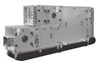
4 Air Handling Units 01 Klimair2 TopAir / TopAir Plus Optima2 KSM Compact unit (plug&play) 4

5 Air Handling Units Functional sections of air handling units Air Handling Units Air Handling Units Air handling units are intended for central preparation of air and allow all basic functions, including: heating, cooling, filtration, humidification, dehumidification, heat recovery and regeneration. 5


, exterior (KZN), for swimming pools (KBN), hygienic (KHN). Compact units plug&pay CompAir CF High energy efficiency.")


.")

6 Air Handling Units Overview Air handling units Air handling units are intended for central preparation of air and allow all basic functions, including: heating, cooling, filtration, humidification, dehumidification, heat recovery and regeneration. There are 38 standard sizes of air handling units available, and they support air volume flow rates of 500 m³/h to m³/h. They all boast excellent thermal and sound insulation as well as a custom selection of high efficiency, functional elements. Types, models Klimair2 Wall thickness: 50 mm. Air flow rate: m³/h. Application: interior (KNN), exterior (KZN), for swimming pools (KBN), hygienic (KHN). Compact units plug&pay CompAir CF High energy efficiency. Air flow rate: m³/h. Within range: Klimair2, TopAir, TopAirP. Version: indoor, outdoor. CompAir RW High energy efficiency. Rotary wheel heat recovery. Air flow rate: m³/h. Within range: Klimair2, TopAir, TopAir Plus. Version: indoor, outdoor. The Selection Program Aircalc++ Klimair2 TopAir / TopAir Plus TopAir Wall thickness: 50 mm. Air flow rate: m³/h. Advantages: new modified range comparing to Klimair2, better design, better fitting, better airtightness. Application: interior (KNN), exterior (KZN), for swimming pools (KBN), hygienic (KHN). TopAir Plus Wall thickness: 50 mm. Air flow rate: m³/h. Advantages: Advantages: as TopAir, but better thermal bridges class compared to the TopAir and also better thermal transmittance (according to the EN 1886). Application: interior (KNN), exterior (KZN), for swimming pools (KBN), hygienic (KHN). For selecting air handling units, we use the multi-language selection program Aircalc++, which is an excellent tool for sales engineers, project designers of air handling unit systems. Besides calculations, the program also allows you to create sketches that can be exported to Auto- CAD, descriptions and the thermodynamic process in the Mollier h x diagram. Software has special module certified according Eurovent and RLT standard. Optima2 KSM Optima2 Wall thickness: 25 mm. Air flow rate: m³/h. Version: indoor. KSM Air flow rate: m³/h. Within range: Optima2. Version: indoor ceiling. Compact unit (plug & play) 6
7 Air Handling Units General Content Page Air Handling Units General 8 Advantages of air handling units 8 Quality 10 Types of air handling units 11 Panels and doors 11 Custom made, modular AHU 12 Klimair2, TopAir, TopAir Plus 12 Indoor version KNN 12 Outdoor version KZN 12 Swimming pool version KBN 13 Hygienic version KHN 14 Standard air handling unit systems in indoor, outdoor and hygienic version 14 Optima2 air handling unit 19 Ceiling mounted units KSM 20 Compact units plug&play 22 CompAir CF, CompAir RW 22 CompAir CF Technical data 24 CompAir RW technical data 26 Selection programme Aircalc++ 28 Designation and ordering key 29 Table of functional units and designation 31 Functional sections of air handling units 7


8 Air Handling Units General General Advantages of air handling units Outstanding flexibility due to adjustable modular construction and a wide selection of air handling unit sizes. A range of 38 sizes allows a combination of various air handling unit cross section widths and heights. An average of 2 to 3 combinations is available for any nominal volume air flow rate Wide application range, from 800 m³/h to m³/h. All air handling functions are provided: ventilation, removal of dust, gas, outdoor and microorganisms, heating, cooling, humidification, and dehumidification. Flexible construction Easy installation due to housing solidity and adaptability to the building entrance conditions, as well as simplicity of interconnection into a set within or outside the housing. Air handling units can be dismantled into any number of particular compact sets, depending on the number of functional sections, unit size, transport options, and building requirements. Low energy consumption and low risk of housing condensation due to quality thermal insulation and air-tightness of housing. Acoustic insulation is made of 50 (25) mm thick rock wool, with fibres oriented vertical to the wall surface. It is non-flammable and it remains stable over time and thus assures the solid housing. Easy maintenance and access Easy maintenance and access to all components, hygienically-friendly construction. Internal surfaces of a high quality housing are flat and smooth. Holding components of functional elements have their sharp edges rounded to the extent practicable. 8


9 Air Handling Units General Functional sections of air handling units Air Handling Units Additional anticorrosion powder-coating or use of stainless materials ensure extended service life. Any combination of steel sheet materials is available. Option to select optimal exhaust air heat or cold recovery system. Plate recuperator. Double plate recuperator. Counterflow plate recuperator. Rotary regenerative heat exchanger. Fin recuperator. Heat pump. High and constant quality of manufacturing process and products. Compliance with the European machinery, low-voltage and electromagnetic adequacy directives. Quality of development, construction, production, and customer service in accordance with ISO Anticorrosion protection Different heat recovery systems Package solution of air handling unit with integrated cooling hydraulic and control systems. Air handling units can be fitted with all the control equipment required for its automatic operation. We can provide the start-up of the unit and train the maintenance personnel to handle properly with the unit. Good sound and thermal insulation Integrated cooling hydraulic system 9


10 Air Handling Units General Quality Quality of air handling units is very important, thus we pay a lot of attention to constant improvement of all business processes and products. Air handling units comply with the ISO 9001, which is how we guarantee quality in development, construction, manufacturing and sales. Air handling units conform with the requirements of the European directives for machinery, low voltage and electromagnetic compatibility. We have aquired GOST certificate for all types of air handling units intended for the Russian market. For our air handling units, intended for the Russian market, the Sanitary- Epidemiological Conclusion Certificate is available. Our hygienic air handling units conform with the norms DIN , EN 3053 and VDI 6022, for which we are TÜV certified. Our explosion-proof models are made in conformity with the Directive 94/9/ EC (ATEX) i.e. the technical documentation for the air handling units has been proven by the notified body (SIQ Ljubljana). The air handling unit Klimair2 aquired a certificate Eurovent (for a housing KNN, KHN and TopAir). Tests for mechanical characteristics and air flow rate were performed according to the norms EN 1886 and EN TÜV certified to ISO 9001:2008 GOST certificate Eurovent certificate TÜV certified to DIN TÜV certified to VDI 6022 TÜV certified to EN

![Concerning assembly of functional units and characteristics of a building, there are available: horizontal air handling units [L], two-stage air handling units [D], parallel air handling units [V],](/docs-images/74/71467647/images/11-1.jpg "vertical air handling units [S], combined air handling units upon agreement. Customized solutions also available.")

11 Air Handling Units General Types of air handling units We have developed different families of air handling units for our clients to select an optimal unit concerning purpose, place of installation, assembly of functional units and building characteristics. Concerning assembly of functional units and characteristics of a building, there are available: horizontal air handling units [L], two-stage air handling units [D], parallel air handling units [V], vertical air handling units [S], combined air handling units upon agreement. Customized solutions also available. Type D Air Handling Units Functional sections of air handling units Panels and doors Klimair2, TopAir, TopAir Plus Top, bottom and side cover panels as well as doors are made of 50 mm double-wall construction, with inner and outer walls of steel sheet and mineral woold thermal insulation filler with density of 100 kg/m³. Glued to a wall with special procedure, the wool also assumes a supporting function, which ensures outstanding quality in terms of not only thermal and sound insulation, but also solidity. Thermal break aluminium profiles effectively prevent unfavourable thermal bridging on the housing. They are used also for CompAir serie. Optima2 panels Top, bottom and side cover panels as well as doors are of 25 mm double-wall construction, with inner and outer walls of steel sheet and mineral wool thermal insulation filler with density of 70 kg/m³. Flammability class Side, bottom and top wall as well as door is class A1 according to DIN 4102, which stands for non-combustible materials. Filter leakage Filter leakage complies with class F9 according to EN 1886 Thermal stability The air handling unit thermal stabillity range is up to +80 C on account of the components sensitive to high temperatures, such as fan bearings, drive belts, filter medium, gaskets, etc. For the temperatures exceeding 40 C, enhanced insulation electric motors shall be installed. Type V Technical data of air handling units Casing 50 mm 50 mm 25 mm Klimair2/ TopAir TopAir Plus Optima2 KNN indoor version KZN outdoor version KHN hygienic version KBN swimmingpool version KSM ceiling units EN 1886 Casing strength D1 D1 D2 Casing air leakage L2 L2 L3 Thermal transmittance T3 T2 T3 Thermal bridging TB3 TB2 TB4 Sound insulation Band 125 [db] Band 250 [db] Band 500 [db] Band 1000 [db] Band 2000 [db] Band 4000 [db] Band 8000 [db] Klimair TopAir / Plus Optima


12 Air Handling Units Custom made, modular AHU Custom made, modular AHU Klimair2, TopAir, TopAir Plus Indoor version KNN The indoor KNN unit air handling unit is the basic version, with galvanized steel sheet exterior and interior. Pipe and other connections are situated on the outer side. Outdoor type KZN The outside KZN air handling unit is made of powder-coated steel sheet; it has a protective roof and special protection hoods and grids at supply air inlet and exhaust air outlet. The connections and control elements are situated in the interior. 12


 c) d) b) Air Handling Units Functional sections of air handling units Standard systems operation regimes of swimming pool air handling units: a) operation without")
13 Air Handling Units Custom made, modular AHU Swimming pool version KBN An appropriate air handling system as well as suitable temperature and humidity control regimes according to water attraction operation, visitors activity, outside air conditions, and optimal energy consumption; these are the basic functional requirements for indoor swimming pool air handling considered when designing the pool Klimair2 / TopAir / TopAir Plus air handling unit. The characteristics of these units are: anti-corrosion materials, adjustable microprocessor controllers, high efficiency heat recovery, energy efficient heat pumps, dehumidification capacity up to 185 kg/h, quality manufacturing, adaptability to room requirements. KBN housing and equipment: housing: panels of 50 mm thickness, with non-flammable insulation, protected with epoxy coating, plate recuperator: high efficient, epoxy coating protection, heat exchanger coil: Cu/Al, epoxy coating; water cooled condenser: pool water resistant, not included in standard equipment; integrated cooling circuit: with hermetic compressor, all necessary control and safety equipment included, supply and exaust fans: with variable frequency electric motor drive, control system: temperature and humidity regulation with DDC control system. a) c) d) b) Air Handling Units Functional sections of air handling units Standard systems operation regimes of swimming pool air handling units: a) operation without dehumidification when the swimming pool is out of use, b) operation with dehumidification when the pool is out of use, c) operation with or without dehumidification when the pool is in use, d) operation during transitional and summer seasons with or without dehumidification, e) operation in summer with high outside temperatures. e) 13

14 Air Handling Units Custom made, modular AHU Hygienic type KHN A new family of our hygienic air handling units comply with the requirements of the standards DIN , EN and VDI 6022 and applies to the hygienic requirements for air handling units. As proved by the aquired certificates, these unit are designed for air handling in the most demanding conditions such as hospitals, pharmaceutical and food industries. In this application is considered: special materials for housing, airtightness, no sharp edges, smoothness, accesibility to reach and clean each segment of AHU, special control system wiring, special filtration levels, special components: lamps, switches, inspection, dampers, flexible connections, fans, coils, humidifiers Standard air handling unit systems in indoor, outdoor and hygienic version Standard system S 23, regenair Air handling unit for heating, cooling and heat recovery (rotary heat exchanger) Heating medium: hot water. Cooling medium: cold water. Continuous (heating and cooling) control of outlet/room air temperature. Limitation of minimal inlet temperature and energy effiecient operation of a rotary heat exchanger Supply (fresh) air 2 Intake air 3 Outlet air 4 Exhaust air 14
. Continuous (heating) and step control (cooling) of exhaust/room air temperature.")
15 Air Handling Units Custom made, modular AHU Standard system S 24, regenair Air handling unit for heating, cooling and heat recovery rotary heat exchanger Heating medium: hot water Cooling medium: refrigerant (direct evaporation). Continuous (heating) and step control (cooling) of exhaust/room air temperature. Limitation of minimal inlet temperature optimal energy efficient operation of a rotary heat exchanger. Note: Compressor and air cooled condenser are installed into air handling unit! Air Handling Units Functional sections of air handling units Standard system S 41, adicool (adiabatic cooling) Air handling unit for heating, cooling, adiabatic cooling, heat recovery and mixing Heating medium: hot water. Cooling medium: cold water (water cooler) and circulating water (contact humidifier). Continuous control (heating and cooling) of exhaust/room air temperature. Limitation of minimal inlet temperature by optimal energy efficient operation of mixing louvre dampers and rotary heat exchanger Supply (fresh) air 2 Intake air 3 Outlet air 4 Exhaust air Standard System S 43, Adiabatic or Evaporative Cooling Adiabatic or evaporative cooling enables air cooling solely by means of pressurized water. If introduced air with temperature of no less than 24 C, the use of classic cooling sets is not necessary. At lower inlet temperature additional classic cooling agregat is still required however its capacity can be decreased at least by half compared to the classic solution. This solution with pressurized water converted into so called cold vapour/steam, is hygienic and it aquired a demanding Hygiene certificate according to the norm VDI 6022 from a competent German institute. Since the summers of Northern and Central Europe are characterized by rather humid outside air, relative air humidity High pressure pump system 15

16 Air Handling Units Custom made, modular AHU reaching between 40 and 50 %, the procedure of spraying water directly into the incoming fresh air flow is not suitable for these environments. This can be executed only by adiabatic cooling, i.e. water is sprayed into the ambient outlet air, which, thus cooled, passes through a plate or rotary heat exchanger transferring its coolness indirectly to the fresh air flow. It is necessary, however, that the recuperator has a sensible heat recovery efficiency of 80 % at least. An example of operation: the outlet air with a temperature of e.g. 26 C and e.g. 50 % relative humidity is humidified to approximately 95 % relative humidity, which decreases its temperature to about 19.5 C. The cooled air then passes through the recuperator outlet side, transferring the coolness to the supply air flow; the temperature of the latter thus drops from 32 C to approximately 24 C. The high-pressure system with water at 70 bar pressure allows considerably more efficient water utilization than the humidification principles known so far; about 80 % of the sprayed water actually evaporates, and thus transfers to air (with classic low-pressure water spray systems, the percentage is much lower, namely 5 %). Evaporative systems can only utilize fresh water, which ensures their hygienic suitability. With evaporative cooling, there is no danger of the Legionella bacteria transferring through the HVAC system, while an additional advantage is water pump power consumption, which amounts to only about 0.55 kw. 1 Nozzle system Standard system S 52, rekupair plate Air handling unit for heating, cooling and heat recovery (plate heat exchanger) Heating medium: hot water. Cooling medium: cold water. Continuous control (heating and cooling) of outlet / ambient temperature. Limited minimum inlet temperature with optimal energy efficient operation of a plate heat exchanger Supply (fresh) air 2 Intake air 3 Outlet air 4 Exhaust air 16
17 Air Handling Units Custom made, modular AHU Standard S 53, rekupair plate Air handling unit for heating, cooling and heat recovery (plate heat exchanger) Heating medium: hot water. Cooling medium: halogen refrigerant (direct evaporation). Continuous (heating) and step control (cooling) of outlet / ambient temperature. Limited minimal inlet temperature with optimal energy efficient operation of a plate heat exchanger. Note: Compressors and air cooled condenser are installed in air handling unit! Air Handling Units Functional sections of air handling units Standard system S 62, rekupair fin (glycol) Air handling unit for heating, cooling and heat recovery (fin-glycol heat exchanger) Heating medium: hot water. Cooling medium: cold water. continuous control (heating and cooling) of outlet/ambient air temperature Limited minimal inlet temperature with optimal energy efficient operation of a fin (glycol) heat exchanger Standard system S 89 Air handling unit for heating, cooling and mixing Heating medium: hot water. Cooling medium: cold water. Continuous (heating and cooling) control of outlet / ambient temperature. Limited minimal inlet temperature with optimal energy efficient operation of mixing louvre dampers Supply (fresh) air 2 Intake air 3 Outlet air 4 Exhaust air 17
18 Air Handling Units Custom made, modular AHU Standard system S 97 Air handling unit for heating, cooling, humidification and mixing. Heating medium: hot water. Cooling medium: cold water. Humidifying medium: steam (independent steam generator). Continuous (heating and cooling) control of outlet / ambient temperature and relative humidity. Limited minimal temperature and maximal relative humidity of inlet (blow-in) air with optimal energy efficient operation of mixing louvre dampers Standard system S 100 Air handling unit for pre-heating, cooling, humidification, auxiliary heating and mixing with continuous (stepless) or step control of relative humidity. Heating medium (for pre-heater and auxiliary heater): hot water. Cooling medium: cold water. Humidifying medium: water (spray humidification). Continuous (pre-heating and auxiliary heating) control of temperature. Continuous or step control of relative humidity of outlet / ambient air. Limited minimal temperature and maximal relative humidity of inlet (blownin) air with optimal energy efficient operation of mixing louvre dampers Supply (fresh) air 2 Intake air 3 Outlet air 4 Exhaust air 18

19 Air Handling Units Custom made, modular AHU Optima2 air handling unit Optima2 AHU is intended only for indoor installation. The housing is compact and easy to install. Inner surfaces are smooth and easy to maintain. The housing sizes remain within the same modular system as known at her older sister Klimair2. Despite the reduced cover panels thickness, its thermal characteristics are kept at a high level, while sound level measurments showed outstanding results, since production technology for panels differs from the previusly used methods. The standard Optima2 air handling unit systems are identical as with the air handling units KNN, indoor version. Application is limited up to the volume air flow m³/h i.e. up to the standard air handling unit cross section 15/15. Optima2 Air Handling Units Functional sections of air handling units Optima2 19


 Installation by means of hanging supports c) Direct wall fixing a) montaža na strop s pomočjo obešal b) Direct ceiling")
20 Air Handling Units Custom made, modular AHU Ceiling mounted units KSM Ceiling air handling units KSM are available either as air handling units in functional sections or as complete products, fitted with all the necessery control and feedback systems, including electric control cabinet. In the latter case, our professional team also starts up the unit, preset the project parameters, trains the staff and provides a functional warranty. These units are designed for air flow rates from 500 up to 4000 m³/h, or for preparation of fresh air in smaller air handling systems. Due to their small height (375 mm), the ceiling air handling units KSM can be installed under the ceiling, within the suspended ceiling or on a wall. Installation a) Installation by means of hanging supports c) Direct wall fixing a) montaža na strop s pomočjo obešal b) Direct ceiling fixing 20
21 Air Handling Units Custom made, modular AHU Standard ceiling mounted air handling systems 1. System: VR, EW, FK 2. System: VR, KW-TA, EW, FK Air Handling Units Functional sections of air handling units 3. System: VR, EW, FK, M, A, VR Sound attenuator S-6 4. Additional functional sections: Electric heater EE Sound attenuator S-9 21


22 Air Handling Units Compact units plug&play Compact units plug&play CompAir CF, CompAir RW CompAir CompAir is a family of air handling units in seven sizes, designed for volume air flow from 500 up to m³/h. The basic characteristics of the unit is high efficient heat recovery of the exhaust air. As an additional option heating and/or cooling can be included. The basic model consists of a high efficient counterflow heat exchanger, an inlet and outlet fans, F7 filters on the inlet side and G4 filter on the outllet side. The basic model is built in one section, so called monoblock. Concerning the customer's requirements the units can be separated in more sections. These units are designed for outdoor and indoor installation. CompAir CF Basic version: CF: highly efficient counterfow heat exchanger with by-pass function, RW: highly efficient rotary wheel, Inlet and outlet fans with electronically commutated motors and required electronics, filter on inlet and outlet side, upon customer s request: accessories and functions. Housing structure: sound and heat insulated aluminium profiiles and polyamid corner profiles, basic option see panels TopAir/Klimair2: T3, TB3 class. Plus option: paneles TopAir Plus; T2, TB2 class. exterior of the panels coated by the RAL Configurations: compact monoblock [M], splitted [S], inside version [I], outside version [O]. CompAir RW Functions: water heater, water cooler, DX cooler, electrical heater, preheater, heater and cooler. 22
23 Air Handling Units Compact units plug&play Accessories: PGD display and remote control, larger controllers, different PCO cards, different sensors, roof for outdoor version, an inlet and outlet hood for outdoor version, dampers with actuators, round duct connections, flexible connections, support feet, syphon., possibilities: continous or step-wise control of heating and cooling, continous control of heat recovery, free cooling function, de-icing protection, setting different air flows, clock card for time schedule, remote control by LCD display, fire sequence, free programming or override, constant pressure control, air flow rate control. Advantages: seven standard sizes cover all the requirements for residential, small and medium size business buildings, high efficiency at maximal air flow reach 90 %, at nominal air flow even up to 93 %, the units are distinguished by the high quality components, the units can be connected to any central control systems with different protocols. Further technical characteristics are available in Technical brochure CompAir on programs/ahu/. Overview of compact air handling units CompAir CF CompAir RW Air flow rate size Legend CF RW Housing Airflow Heat recovery Type mm m³/h Type Up to % Klimair2/ TopAir/ TopAir Plus Klimair2/ TopAir/ TopAir Plus m³/h Air Handling Units Functional sections of air handling units 23
24 Air Handling Units Compact units plug&play CompAir CF Technical data Size Airflow range: (m³/h) Electrical supply: (V) 1 x x x x x x x 380 Motor and fan type: EC Radial fan backwards curved without housing Frequency: 50 Hz 50 Hz 50 Hz 50 Hz 50 Hz 50 Hz 50 Hz Input power: 448 W 1000 W 1000 W 1700 W 2950 W 2800 W 5500 W Imax: 2,8 A 1,63 A 1,7 A 2,6 A 4,6 A 4,4 A 8,8 A Insulation: 50mm mineral wool Color: RAL 7035 Filter type: Filter class: Damper exaust: Damper supply: Condense connection: Panel filter G4/G7 Outlet air damper 24 V actuator Supply (fresh air) damper 24 V actuator DN40 Duct dimension (mm): 640 x x x x x x x 855 Heater connections: 3/4 3/4 3/4 3/4 3/4 3/4 1 Cooler connections: 3/ /2 1 1/2 2 Dimension Splitted (mm): Length (mm): Length with heater or cooler (mm): Length with heater and cooler (mm): Height (mm): Width (mm): Dimensions monoblock (mm): Length inside/outside (mm): 1690/ / / /2200 Length with heater or cooler (mm): Length with heater and cooler (mm): Height (mm): Width (mm): Efficiency: up to 93 % Heat recovery: High efficiency counter flow plate heat exchanger Operating temperature: -20 C to 40 C 24


25 Air Handling Units Compact units plug&play CompAir CF unit dimensions Monoblock inside version Air Handling Units C C A A C C A A Functional sections of air handling units B L B Monoblock outside version B1 E F B1 B2 H H H A1 AxC AxC AxC AxC C A AxC AxC C A B L1 B mm A A B B B C L * 2850* 2850* L * 3180* 3180* H E F * Splitted version dimensions 25
26 Air Handling Units Compact units plug&play CompAir RW technical data Size Airflow range: (m³/h) Electrical supply: (V) 3 x x x x x x 380 Motor and fan type: EC Radial fan backwards curved without housing Frequency: 50 Hz 50 Hz 50 Hz 50 Hz 50 Hz 50 Hz Input power: 1000 W 1000 W 1700 W 2950 W 2800 W 5500 W Imax: 1,63 A 1,7 A 2,6 A 4,6 A 4,4 A 8,8 A Insulation: 50mm mineral wool Color: RAL 7035 Filter type: Filter class: Damper exaust: Damper supply: Condense connection: Panel filter G4/G7 Outlet air damper 24 V actuator Supply (fresh air) damper 24 V actuator DN40 Duct dimension (mm): 935x x x x x x 840 Heater connections: 3/4 3/4 3/4 3/4 3/4 1 Cooler connections: /2 1 1/2 2 Dimension Splitted (mm): Length (mm): Length with heater or cooler (mm): Length with heater and cooler (mm): Height (mm): Width (mm): Dimensions monoblock (mm): Length inside/outside (mm): Length with heater or cooler (mm): Length with heater and cooler (mm): Height (mm): Width (mm): Efficiency: up to 85 % Heat recovery: Rotary wheel 250mm Operating temperature: -20 C to 40 C 26

27 Air Handling Units Compact units plug&play CompAir RW unit dimensions Air Handling Units C A AxC AxC C H A C A H AxC AxC B L B C A H Functional sections of air handling units B1 E B1 H C A AxC H C A AxC B L1 B mm A B B C L * 1970* 1970* L * 1970* 1970* H E *Splitted version dimensions 27


28 Air Handling Units Selection programme Aircalc++ Selection programme Aircalc++ Selection programme Aircalc++ is an efficient tool for project engineers. Software A precise definition of an air handling unit. Wide range of records and drawings. Archiving of the calculations and projects. Excellent internet transmission of calculations and plans. Direct transmission of calculations into the production. Process outline in h-x diagram. Fan noise curve plotting. Export of drawings to dwg format. Eurovent certified! Drawings different views H-x diagram Size selection Fan noise curve 28
29 Air Handling Units Designation and ordering key Designation and ordering key Ordering key for custom made air handling units Air Handling Units K X N X d50 / - X X, X,.. X - X *** / -X X, X,.. X - X Access side (From the point of air flow direction*) L left R right functional sections in sequence reverse to the flow of air Functional sections of air handling units unit dimensions width/height d wall-thickness 50 mm L horizontal D two-stage V parallel S vertical K combined N unit design N indoor install. type Z outdoor install. type H hygienic grade type B pool type K air handling unit * With two stage design, the access side specification applies to the intake unit part. accessories specified descriptively Designation example: KNND 9/9 d50-st, VR, KW-TA, FR, EW, RPDM-TA- -FK, M-6-2, J, ST, ST, VR, FK-3, J, ST-R 29
30 Air Handling Units Designation and ordering key Ordering key for Compair CF (Plus) 1000-R-I-M-EW/DA14/FC1234/RC1234/PH13/FT + Accessories 2 Accessories 3: FT feet (empty) without feet PH13 protection hood on connections 1,3 PH1 protection hood on connection 1 (empty) without protection hood RC1234 round connections on connections 1,2,3,4 RC24 round connections on connections 2,4 (empty) without round connections FC1234 flexible canvas on connections 1,2,3,4 FC24 flexible canvas on connections 2,4 (empty) without flexible canvas DA14 dampers on connections 1,4 DA1 damper on connection 1 (empty) without damper Accessories 1, function: E empty section EW water heater KW water cooler EW+KW water heater + water cooler EW+KD water heater + dx cooler KD dx cooler EWV water pre-heater EE electrical heater EWV,EW water pre-heater, heater EWV,EW+KW water pre-heater, heater + water cooler (empty) without function Unit type: M monoblock S splitted I inside O outside R right L left Unit size: Housing type: Plus Plus housing (empty) basic housing Accessories see connections: 1) supply intake 2) supply outlet 3) exhaust intake 4) exhaust outlet Heat recovery type: CF counter flow heat exchanger RW rotary wheel exchanger 30
31 Air Handling Units Functional units and designations Functional units and designations Air Handling Units New designation Description VR VD VF EW ED Fan section belt driven fan Fan section direct driven fan Fan section freewheeling fan Heating section with water heater Heating section with steam heater Functional sections of air handling units EK EE Heating section with condenser Heating section with electric heater EGI FR BLW BD Heating section with indirect gas heater Anti-freezing protection section Humidification section with spray humidifier Humidification section with steam humidifier BWA BWH KW KD KW-TA KD-TA TA KO A M MD U FK FZ FT FTT FM FAK FA S Humidification section with contact humidifier Humidification section with high pressure humidifier Cooling section with water cooler Cooling section with direct evaporator Cooling section with water cooler with droplet eliminator Cooling section with direct evaporator with droplet eliminator Droplet eliminator Compressor section Intake (pressure) section with single control damper, with flexible duct connection Mixing section with two control dampers, with flexible duct connection Dual mixing section with three control dampers, with flexible duct connection Circulation section Cartridge filter section ZIGZAG filter section Bag filter section Bag filter section model with door Metal filter section Activated carbon filter section Absolute filter section Sound attenuation section 31
32 Air Handling Units Functional units and designations New designation LU RKE RKK RKK-TA RPD RPDC RPDB RRG RRF RWR D J ST H WSG EEJ Description Empty angle section Recuperation section with fin recuperator (heating part) Recuperation section with fin recuperator (cooling part) Recuperation section with fin recuperator (cooling part) and droplet eliminator Recuperation section with plate recuperator (diagonal design) Recuperation section with counter flow heat exchanger Recuperation section with double plate heat exchanger Recuperation section with rotary recuperator encased design Recuperation section with rotary recuperator flanged design Recuperation section with heat pipe Diffuser section Control damper Flexible connection Protection hood Protection grille Control damper electric heater 32
33 Air Handling Units Functional units and designations RADIAL FAN SECTION WATER HEATER SECTION STEAM HEATER SECTION CONDENSER SECTION ANTI-FREEZING PROTECTION SECTION CIRCUIT SECTION: HEATING, COOLING, FIN RECUPERATION Air Handling Units ELECTRIC HEATER SECTION GAS HEATER SECTION SPRAY HUMIDIFIER SECTION STEAM HUMIDIFIER SECTION WITH ELECTRIC STEAM GENERATOR STEAM HUMIDIFIER WITH OUTSIDE STEAM SECTION CONTACT HUMIDIFIER WITH CIRCULATING WATER SECTION Functional sections of air handling units CONTACT HUMIDIFIER WITH DIRECT WATER SECTION WATER COOLER SECTION DIRECT EVAPORATOR SECTION DROPLET ELIMINATOR COMPRESSOR SECTION SECTION WITH ONE CONTROL DAMPER SECTION WITH TWO CONTROL DAMPERS DUAL MIXING SECTION CONTROL DAMPER AIR-TIGHT CONTROL DAMPER FILTRATION CLASS G3 FILTER SECTION FILTRATION CLASS G4 FILTER SECTION G3 G3 G4 FILTRATION CLASS F5 FILTER SECTION FILTRATION CLASS F6 FILTER SECTION FILTRATION CLASS F7 FILTER SECTION FILTRATION CLASS F9 FILTER SECTION FILTRATION CLASS H10 ABSOLUTE FILTER SECTION FILTRATION CLASS H11 ABSOLUTE FILTER SECTION H11 H10 F9 F7 F6 F5 F6 F7 F9 H10 H11 FILTRATION CLASS H12 ABSOLUTE FILTER SECTION FILTRATION CLASS H13 ABSOLUTE FILTER SECTION ACTIVATED CHARCOAL FILTER SECTION ELECTROSTATIC FILTER SECTION SOUND ATTENUATION SECTION EMPTY SECTION H13 H12 H12 H13 FIN RECUPERATOR SECTION HEATING PART FIN RECUPERATOR SECTION COOLING PART PLATE RECUPERATOR SECTION ROTARY REGENERATOR SECTION HEAT PIPE SECTION SHORT DIFFUSER SECTION ELECTRIC CONTROL CABINET SECTION HANDLE POSITION OPEN HANDLE POSITION CLOSED AIR DIRECTION MEDIUM DIRECTION CONTROL DAMPER OPEN CONTROL DAMPER CLOSED 33
34 Air Handling Units Functional units and designations FILTRATION CLASS H12 ABSOLUTE FILTER SECTION FILTRATION CLASS H13 ABSOLUTE FILTER SECTION ACTIVATED CHARCOAL FILTER SECTION ELECTROSTATIC FILTER SECTION SOUND ATTENUATION SECTION EMPTY SECTION H13 H12 H12 H13 FIN RECUPERATOR SECTION HEATING PART FIN RECUPERATOR SECTION COOLING PART PLATE RECUPERATOR SECTION ROTARY REGENERATOR SECTION HEAT PIPE SECTION SHORT DIFFUSER SECTION ELECTRIC CONTROL CABINET SECTION HANDLE POSITION OPEN HANDLE POSITION CLOSED AIR DIRECTION MEDIUM DIRECTION CONTROL DAMPER OPEN CONTROL DAMPER CLOSED CONDENSATE DRAIN TRAP DIMENSIONING MEDIUM ENTRY RED COLOUR HEATING FUNCTION MEDIUM EXIT BLUE COLOUR MEDIUM ENTRY BLUE COLOUR COOLING FUNCTION MEDIUM EXIT RED COLOUR 34
35 Air Handling Units Functional units and designations Functional sections of air handling units Air Handling Units 35
36 Functional sections of air handling units 02 Fan section Heating section Humidification section Cooling section Filter section Heat recovery section 36

37 Functional sections of air handling units Functional sections of air handling units Air Handling Units Functional sections of air handling units Fan, heating, humidification, cooling, air regulating, filter, sound attenuation and heat recovery section can be selected for each air handling unit. 37


 in air conditioning")
 or water cooler (type HV), steam heater (type GP), direct evaporator (type KD), condenser (type KF, AVK), finned heat exchangers.")


38 Functional sections of air handling units General Overview Fan section Heating section Humidification section Cooling section Filter section Heat recovery section Fan section Fan section is applied in ventilation and air conditioning engineering. They are installed in air handling units, or applied as stand alone elements, built into different distribution ducts to maintain the required or specified flow rate. We have different variants of fan section: belt driven fan, direct driven fan external rotor electric motor, direct driven fan electronically commutated electric motor with external rotor, plug fan (without spiral housing). Heating section Finned heat exchangers are applied in air heating, cooling and dehumidifying with different media (water, water/antifreeze mixtures, cooling media, oils, steam) in air conditioning and industry. They are designed for installation in A/C units or air ducts. Heat exchangers are used as: water heater (type GV) or water cooler (type HV), steam heater (type GP), direct evaporator (type KD), condenser (type KF, AVK), finned heat exchangers. Humidification section Humidification section provides for the increasing of the moisture of the inlet air to the suitable temperature which depends of the working environment. Types of humidification units: humidification section with spray humidifier, humidification section with steam humidifier, humidification section with contact humidifier, high pressure shower humidifier. Cooling section Cooling section provides for the cooling of the inlet air in the summer season. It is designed regarding the inlet parameters and flow rate. We have different types of cooling units: cooling section with water cooler, cooling section with water cooler with droplet eliminator, cooling section with direct evaporator. Heat recovery section Recuperation section intends to return back the input energy in the system heating in the winter season and cooling in the summer season. The efficiency of the system with the recuperation section is from 50 to 90 %. This means a huge savings of energy and money. Types of recuperation units: recuperation section with fin recuperator, recuperation section with plate recuperator, regeneration section with rotary regenerator. recuperation section with double plate recuperator recuperation section with counter flow recuperator Filter section Filter section provides for the quality of inlet air. Regarding the quality of the desired air and the level of filtration different filters are installed from the simple ones to the more demanding which are installed in the hospitals and laboratories. Different types of filters: cartridge, zigzag, bag, band, metal, absolute and activated charcoal filter section. 38
39 Functional sections of air handling units Content Page Air handling unit size specifications 40 Cross section dimensions 40 Air handling unit size specification guidelines 41 Quick specification of air handling unit sizes 42 Quick selection diagram 43 Descriptions and dimensions of functional sections 44 Fan section 44 Belt driven fan vertical design 45 Direct driven fan: VD 49 Plug fan: VF 46 Diffuser section: D 46 Heating section 47 Heating section with water heater: EW 47 Heating section with steam heater: ED 48 Heating section with condenser: EK 48 Heating section with electric heater: EE 49 Heating section with indirect gas heater: EGI 50 Section with anti-freezing protection: FR 51 Humidification section 52 Humidification section with spray humidifier: BLW 52 Humidification section with steam humidifier: BD 54 Humidification section with honey comb humidifier: BWA 55 Cooling section 59 Cooling unit with water cooler: KW 59 Cooling section with water cooler with droplet eliminator: KW-TA 60 Drain trap 61 Page Cooling section with direct evaporator: KD 62 Compressor section: KO 62 Filter section 63 Cartridge filter section 63 Zigzag filter section: FZ 64 Bag filter section: FT 65 Bag filter section: FTT 65 Metal filter section: FM 66 Activated charcoal filter section: FAK 66 Absolute filter section: FA 67 Sound attenuation section 68 Sound attenuation section: S 68 Heat recovery section 69 Recuperation section with fin recuperator heater: RKE 69 Recuperation section with fin recuperator cooler: RKK 69 Recuperation section with plate recuperator diagonal design with droplet eliminator and cartridge filter: RPD_-TA-FK 70 Recuperation section with double plate 71 heat exchanger RPBD Recuperation section with counter 71 flow heat exchanger RPDC Regeneration section with rotary regenerator encased type: RRG 72 Regeneration section with rotary regenerator flanged type: RRF 73 Explosion proof air handling unit type 74 Air Handling Units Functional sections of air handling units 39
40 Functional sections of air handling units Air handling unit size specifications Air handling unit size specifications Cross section dimensions H₂ HN H₁ h B₁ 50 B 50 h = 80 HN = mm h = 100 HN = mm 50 H 50 Size B (mm) H (mm) B1 (mm) H1 (mm) h (mm) H2 (mm) Aef (m²) 6/ ,20 9/ ,29 6/ ,33 6/ ,40 9/ ,58 12/ ,77 6/ ,59 9/ ,87 12/ ,15 15/ ,43 18/ ,71 9/ ,17 12/ ,54 15/ ,91 18/ ,28 21/ ,65 12/ ,92 15/ ,39 18/ ,85 21/ ,32 24/ ,78 15/ ,86 18/ ,42 21/ ,98 24/ ,54 27/ ,10 18/ ,99 21/ ,64 24/ ,29 27/ ,95 30/ ,60 21/ ,31 24/ ,05 27/ ,80 30/ ,54 24/ ,81 Bigger units available on customer's request. 40
41 Functional sections of air handling units Air handling unit size specifications Air handling unit size specification guidelines According to RAL-GZ 652 Control dampers, duct connections and mixing units (not applicable to circulation and bypass dampers) Intake velocity vzr 8 m/s Intake angle (damper to functional element, e.g. filter) α 35 Outlet angle (functional element, e.g. filter, to damper) β 25 Outdoor air handling units Intake side Intake velocity v zr Pressure side Protection grille 2,5 m/s 4,0 m/s Droplet eliminator 3,5 m/s 5,0 m/s Hoods 4,5 m/s 6,0 m/s Filters Air Handling Units Functional sections of air handling units Filter surface Intake velocity Final pressure drop Final pressure drop Pressure drop for dimensioning purposes min 10 m² per 1 m² cross section (not applicable to coarse filters) v zr 3,2 m/s (not applicable to activated carbon filters, absolute filters, etc.) F5 F7 pk = 200 Pa F8 F9 pk = 300 Pa p = ( pz + pk)/2 Air heaters and coolers Heater Cooler Intake velocity to finned surface v zr volume air flow rate m³/h v zr 4 m/s volume air flow rate > m³/h v zr 3,5 m/s Water side pressure drop p 20 kpa p 50 kpa Fin pitch 2,0 mm 2,4 mm Waste heat recovery sections Plate recuperator without bypass m³/h > m³/h Plate recuperator with bypass m³/h > m³/h Minimum heat recovery factor ( ¹) (-) 0,50 0,55 0,45 0,50 Maximum pressure drop ( Pmax²) (Pa) Maximum air leakage (Leakage)³ (%) Rotary regenerator 0, ,0 Pipe circuit system fin regenerator 0, Heat pipe without bypass 0, ,25 Heat pipe with bypass 0, ,25 0,25 0,25 0,25 0,25 1. At air flow mass ratio 1,0 2. In dry air conditions; with higher heat recovery factors, a higher pressure drop percentage is allowed 3. At pressure difference 400 Pa 41
42 Functional sections of air handling units Air handling unit size specifications Quick specification of air handling unit sizes Size A TP (m²) V TP * (m³/h) V FK (m³/h) V FT (m³/h) V RPDK (m³/h) V RPDM (m³/h) V RPDG (m³/h) 6/3 0, /3 0, /5 0, /6 0, /6 0, /6 0, /9 0, /9 0, /9 0, /9 1, /9 1, /12 0, /12 1, /12 1, /12 1, /12 2, /15 1, /15 1, /15 2, /15 2, /15 3, /18 2, /18 2, /18 3, /18 3, /18 4, /21 3, /21 3, /21 4, /21 5, /21 5, /24 2, /24 2, /24 2, /24 3, /27 2, A TP V TP V FK V FT V RPDK V RPDM V PLRG V RR heat exchanger cross section size maximum volume air flow rate across heat exchanger (heater, cooler) maximum volume air flow rate across cartridge filter maximum volume air flow rate across bag filter maximum volume air flow rate across plate recuperator (low efficiency, pressure drop ~ 300 Pa) maximum volume air flow rate across plate recuperator (medium efficiency, pressure drop ~ 300 Pa) maximum volume air flow rate across plate recuperator (high efficiency, pressure drop ~ 300 Pa) volume air flow rate across rotary regenerator based on known data L 1 - unit overall length - efficiency p zuzr - external air side pressure drop p zazr - waste air side pressure drop * air intake velocity vzr across cross section ATP: VTP m³/h vzr = 4,0 m/s VTP > m³/h vzr = 3,5 m/s 42
43 Functional sections of air handling units Air handling unit size specifications Quick selection diagram Cross unit Section size m² Air Handling Units Functional sections of air handling units Legend RANGE OF USE VOLUME AIR AIR FLOW RATE x m³/h x m 3 /h heater, cooler cartridge filter RANGE OF USE plate recuperator - small VOLUME AIR FLOW plate recuperator RATE x medium m 3 /h heater, heater, cooler cooler cartige cartridge filter filter bag bag filter filter bag filter plate recuperator - large plate plate recuperator recuperator small - small plate plate recuperator recuperator medium - medium plate plate recuperator recuperator large- large 43
44 Functional sections of air handling units Descriptions and dimensions of functional sections Descriptions and dimensions of functional sections Fan section A fan section consists of a section housing, holding components, and a fan with a number of possible drive variants: belt driven fan, direct driven fan external rotor electric motor, direct driven fan electronically commutated electric motor with external rotor, plug fan (without spiral housing). The fan with its drive mechanism is mounted on the section housing guides by means of vibration insulators, while on the pressure side it is connected to the housing by means of a flexible duct connection. Such installation prevents the transmission of vibrations to the housing. Degree of protection according to DIN EN The motors are designed for degree of protection IP 55 in accordance with DIN EN (Absolute protection of moving and live parts, protection against harmful dust accumulation and waterspouts.) In general, the fan section is characterised by the following: fan impeller provided with general anti-corrosion protection, fan housing made of galvanised steel sheet, fan housing in hygienic grade units fitted with condensate drain, and from fan size 400 and above, with cleaning opening, fan and motor structural frame made of galvanised steel sheet, fan with drive motor can be dismounted from unit housing, section fitted with double-wall inspection window and internal lighting, section housing fitted with cable sleeves for drive motor power cabling, with unit sizes 6/3 and 9/3, access door fitted with terminal box for drive motor wiring, access door protected against unauthorised opening or entry by means of mechanical interlock, if no electric control box is in air handling unit close proximity, i.e. within visual field, each unit is fitted with lockable service switch, section housing fitted with interior pressure measuring fittings. Electric motor rated power The term rated power refers to constant operation according to DIN EN , with 50 Hz frequency, 40 C temperature and at an altitude up to 1000 m. With 60 Hz frequency, the rated power increases in accordance with the correction factors listed below: Electric motor housing size Number of poles Correction factor for 60 Hz operation to 8 1,15 2 1,12 180M 200L 4 1,15 6 and 8 1,2 AC EFF1 and EFF2 motors available. EC motors available. Note: Belt driven fan mechanical safety is ensured by installation inside the unit, which prevents access during fan operation. 44
45 Functional sections of air handling units Descriptions and dimensions of functional sections Belt driven fan: VR The fan is mounted on the structural frame consisting of two longitudinal and two transversal C-profiles. Mounted on the structural frame is also a tensioning plate with an electric motor, which serves for corrective adjustment of belt tension. The electric motor drives the fan via V-belts and pulleys. The fan structural frame is mounted on the unit housing by means of vibration insulators. The flexible duct connection prevents the transfer of fan pressure flange vibrations to the unit housing (picture 15). The fan drive electric motors fall into insulation class F; however, at nominal load and nominal tension, insulation temperature does not exceed insulation class B. A stream of air with temperature ranging from -30 C minimum to +55 C maximum and humidity ranging from 5 % minimum to 95 % maximum flows across the electric motors installed in the air handling unit. Air Handling Units Functional sections of air handling units Belt driven fan horizontal design Belt driven fan vertical design 45
46 Functional sections of air handling units Descriptions and dimensions of functional sections Plug fan: VF This fan has no spiral housing and is directly driven by an electric motor via its shaft. The electric motor is mounted on the fan frame by a base plate. The fan structural frame is fixed to the unit housing by means of vibration insulators. A flexible duct connection prevents fan pressure flange vibrations from transferring to the unit housing. AC and EC motors available. Connection types for plug fan section sizes 6/5 24/27: Diffuser section: D 46
47 Functional sections of air handling units Descriptions and dimensions of functional sections Heating section Heating section with water heater: EW A water heater consists of a frame, fin package, a collection pipe and a distribution pipe. The fin package is formed by copper tubes, to which aluminium fins are joined by means of mechanical expansion. The collection and distribution pipes, which interconnect the fin package tubes, are fitted with an air-bleed and drain valve. The frame protects pipe elbows and serves for mounting the heater in the unit. The collection pipe, distribution pipe and solder joints are protected against corrosion with temperature resistant coating. Every water heater is tested for tightness in a water bath at a test pressure corresponding to the operating pressure. If the water heater has a pre-heating function, there is an anti-freeze protection section (FR) situated behind it. The water heater is mounted in the housing by means of guides allowing its removal in case of defect or damage. Thus, a free area of a width at least 1.3 times the external width of the air handling unit is to be provided at the unit access side. 6/3 30/21 21/24 24/27 Air Handling Units Functional sections of air handling units 47
48 Functional sections of air handling units Descriptions and dimensions of functional sections Heating section with steam heater: ED Steam heater consists of a frame and aluminium fin package, into which copper, collection and distribution pipes are fitted. Aluminium fins and copper pipes are joined by means of mechanical expansion. The collection and distribution pipes, which interconnect the copper pipes, are made of steel and are fitted with a thread or flange connection and an air-bleed and drain valve. The steam heater frame protects pipe elbows and serves for mounting the heater in the unit. The water heater is fitted into the housing by means of guides allowing easier removal. The collection pipe, distribution pipe and solder joints are protected against corrosion with temperature resistant coating. Steam heater (GP type): working medium steam, utilizing only saturated steam condensation heat. Serviceable up to 9 bar maximum. The steam heater is mounted in the housing by means of guides, allowing its removal in case of defect or damage. Thus, a free area of a width at least 1.3 times the external width of the air handling unit is to be provided at the unit access side. Heating section with condenser: EK 48
49 Functional sections of air handling units Descriptions and dimensions of functional sections Heating section with electric heater: EE An electric heater section consists of a section housing, an electric air heater, a protection thermostat and a security temperature sensor. The electric air heater consists of a galvanised steel sheet frame, electric heating elements (resistors) with stainless steel cooling fins, ABS or polycarbonate terminal box mounted on the outer side of the section cover panel, cable glands, silicon insulated leads and terminals. The electric heater is mounted in the housing by means of guides allowing its removal in case of defect or damage. Thus, when installing the air handling unit, a free area of a width at least 1.3 times the external width of the air handling unit is to be provided at the unit access side. Selection and installation guidelines: EE The resistors are connected to 3 x 220 V supply voltage, and reach a high surface temperature of ~ 350 C during operation. Air flow velocity through the electric air heater shall not be less than 2 m/s, and air flow shall be evenly distributed across the entire cross section. Functional sections with temperature sensitive components shall be separated from the electric heater section with an empty section of no less than 600 mm length. If the electric air heater section is installed downstream of the fan section (the fan blowing into the heater), there should be an empty section (with a length of L=(H+B)/2 H represents air handling unit height, B its width but in no case less than 600 mm) installed between these two. The electric heater shall not be started until the fan has established a sufficient air flow rate. After the electric heater switches off, the fan shall continue to operate for an additional 3 to 5 minutes for the heating elements to cool. The security temperature sensor and thermostat sensors shall be located in the heater upper area, above the resistors, where, in case of air flow failure, the temperature is highest. The electric air heater is not water tight; therefore, this heating section shall not be installed where exposed to water or steam. Air Handling Units Functional sections of air handling units 49
50 Functional sections of air handling units Descriptions and dimensions of functional sections Heating section with indirect gas heater: EGI An indirect gas heater section consists of a section housing and an indirect gas heater. The basic indirect gas heater section outline, applicable to all indirect gas heater types, is shown in picture. The indirect gas heater consists of a heat exchanger, a pressure gas burner, a burner (gas) train, and monitoring and safety equipment. The stainless steel sheet heat exchanger consists of a combustion chamber, coil set, and a collection chamber with a flue gas pipe. There is a flue gas condensate collection and drain pan fitted below the heat exchanger. The gas burner is flange-mounted to the combustion chamber opening from the outer (access) side of the section housing, while the flue pipe is routed through the section housing back wall. The declared minimum surrounding temperature for the gas burner normal operation is -15 C. Selection and installation guidelines Indirect gas heater section shall always be located in the positive pressure part of the air handling unit downstream of the supply fan in order to prevent the supply air and flue gas from mixing in case of heat exchanger damage. Predicted on the left and right sides of the gas heater section are empty sections of 600 mm length, with access into the heater section for the purpose of inspection. The pan drain line from the section bottom and the gas heater drain line from the section back wall shall be connected to the drainage through a trap and an acid neutralizer. The safety pressure switch, safety thermostat and security temperature sensor, and operation thermostat shall always be fitted on the section housing outer side. With outdoor air handling units, these appliances as well as the burner shall be protected with a watertight and thermally insulated protection chamber. The gas burner shall be mounted to the combustion chamber opening from the outer side of the section housing by means of flanges, made to a size correspondent to the type and size of the gas burner. With indoor air handling units, always ensure sufficient combustion air supply, natural machine room ventilation, and flue gas exhaust. With outdoor air handling units, the gas burner is protected from the weather conditions (wind, rain, snow, etc.) with a watertight and thermally insulated protection chamber, the bottom of which has an opening for combustion air supply. The protection chamber has to be of such size as to shield not only the burner, but also the safety pressure switch, safety thermostat and security temperature sensor, and operation thermostat, and to provide enough room (to the left and right of the gas burner) for the gas train installation. As regards the design of the flue pipe, consult the competent chimney sweep service. If the supply of a chimneyequipped unit is required, the chimney has to be dimensioned and installed in accordance with the valid laws, regulations and standards. Due to the chimney service approval acquisition, a complete plan (including flue gas condensate drain and neutralisation) is required. The flue pipe shall be routed in accordance with the requirements for gas appliances. The pipe-to-chimney joint shall be watertight to prevent any uncontrolled condensate leakage to the environment in case of flue gas condensation. The flue pipe does not require natural draught. Electric cables shall not be laid inside the section housing. With outdoor air handling units, the cables can be led through the gas burner protection chamber (but shall not hinder the unit access), or laid, upon design engineer and customer agreement, across a free outer surface (back wall, bottom, etc.). The gas heater section design shall predict a connection for external air natural access into the interior (cooling purposes). A top or side opening shall be fitted with a spring drive damper and duct-connected to the outside of the building. The damper and duct shall be thermally insulated with nonflammable insulation material. In case of power failure or any other defect which results in sudden interruption of cooling or unit overheating the damper shall open, thus enabling the gas heater natural cooling. All electric cables installed inside the housing in the sections left and right to the gas heater unit, as well as cable convections and protection pipes shall be thermally insulated with high temperature resistant insulation. For the purpose of outside air filtration, a metal filter with no sealing strip (EPDM) or bottom pan (unless grease is filtered) shall be used. For the purpose of vibration and sound insulation between the housing and the fan upstream of the gas heater, use a flexible duct connection (canvas) of high temperature resistant and non-flammable material according to DIN To insulate the vibrations of the fan upstream of the gas heater, use spring vibration insulators. For potential equalization of the fan upstream of the gas heater, use a noninsulated Cu conductor. The volume flow rate of the air passing across the combustion chamber and coil set must never fall below the minimum value required for the cooling of heat exchanger walls. Thus, check the following prior to the section start-up: installation and operation of the thermostat provided to monitor and maintain the heat exchanger outlet air temperature within the 50 C to 60 C range, installation and operation of the bypass damper electric motor drive and its limit switch; in case of power failure or any other defect which results in sudden interruption of cooling or unit overheating the damper must open, thus enabling the gas heater natural cooling. Motor-drive-limit-switch-actuated gas burner switch-off or prevention of operation in the event of an 80-percent closure on the part of the damper which controls heat exchanger cooling, Installation and operation of the safety air flow rate scale provided for the gas burner switch-off in case of insufficient air flow rate across the heat exchanger, operation of the safety pressure switch provided for the gas burner switch-off in case of exceeding overpressure in the combustion chamber, installation and operation of the safety thermostat provided for gas burner automatic shut-off if air temperature in the chamber above the heat exchanger exceeds approx. 70 C, installation and operation of the safety thermostat (security temperature sensor) provided to switch-off and block the gas burner if air temperature in the chamber above the heat exchanger exceeds approx. 90 C; gas burner restart requires manual intervention, installation and operation of the time relay provided to ensure prolonged fan operation and to prevent the closing of the part of the bypass damper controlling the air flow rate across the heat exchanger after gas burner switch-off; heat exchanger tightness and flue gas exhaust. The gas supply connection and burner start-up shall be executed only by authorised and qualified personnel, following the manufacturer s instructions, design specifications and regulations in force. 50
51 Functional sections of air handling units Descriptions and dimensions of functional sections Combustion chamber 2. Coil set 3. Flue pipe 4. Gas burner with heating power continuous (stepless) control 5. Top-to-heater and bottom-to-heater air directing baffle 6. Back-wall-to-heater air directing regulator 7. Safety thermostat set to 80 C and security temperature sensor set to 90 C 7.1. Safety thermostats and security temperature sensor 8. Differential pressure switch with a range up to 500 pa 8.1. Pressure measuring tube 9. Tube for sensor entry (length: 400 mm) 10. Collection chamber condensate drain 11. Pan with bottom drain Air Handling Units Functional sections of air handling units Section with anti-freeze protection: FR The anti-freeze protection device employed is a freeze sensor. With indoor and hygienic grade air handling units, its housing is mounted on the FR section cover panel outer surface, while with outdoor air handling units, on the frame inside the section housing. A 2- or 6-metre capillary tube fixed to the FR frame is evenly routed across the cross section inside the section housing. The FR section frame is fixed to the FR section cover panel and mounted on guides, which allows its removal. 51
52 Functional sections of air handling units Descriptions and dimensions of functional sections Humidification section Humidification section with spray humidifier: BLW , A spray humidifier section consists of a single-wall housing, a pool and other components, all made of steel sheet On request, the housing and pool can be additionally thermally insulated from the outer sides by means of 50 mm thick mineral wool. The whole pool bottom surface leans towards the drain connection, which is situated at the lowest point of the bottom. The air flow directing rectifier and droplet eliminator consist of stainless steel frames and polypropylene fins (blades) resistant to temperatures up to +125 C. For the purpose of cleaning, they can be dismantled from the section housing. The polyvinyl-chloride (PVC) pipe system consists of a pressure line, internal distribution piping, water spray nozzles, rinse and drain pipes, and a water supply pipe. The inspection door is fitted with a circular polycarbonate window to allow inspection of the section interior during operation. A shutter covers the window on the outer side, but can be lifted for inspection. A light for the humidification section lighting is fitted on the front panel outer side. The flanged pump has grey cast iron housing, a brass impeller, and a stainless steel shaft, or, depending on the water quality, can be entirely made of stainless steel. Together with the drive motor, it is mounted on the water container from the outer side by means of support brackets. A level switch prevents dry operation. Larger sections have a load bearing grid installed in the upper part of the water container above the maximum water level. B A C D Manometer in pressure line 2. Stop valve before manometer 3. Droplet eliminator 4. Electric switch 5. Power distribution box 6. Light 7. Manual 2-way valve for rinsing 8. 2-Way valve in pressure line 9. Door with inspection window 10. Air flow directing rectifier 11. Quick water fill valve 12. Level switch minimum water level maintenance 13. Overflow pipe with trap for p 1000 pa 14. Intake strainer 15. Drain pipe 16. Housing 17. Pressure nozzle 18. Container 19. Pressure distribution piping 20. Ball cock maximum water level maintenance 21. Pump A B C D Dry air intake Humidified air outlet Fresh water supply connection Container water drain connection 52
53 Functional sections of air handling units Descriptions and dimensions of functional sections Water treatment Higher salt concentrations in spray water, caused by water evaporation (air humidification), increase the risk of excessive precipitation in the humidification section water part and pipes. Out of a number of precipitation preventing methods, an appropriate one should be employed according to the importance of the humidification section operation, and water hardness. A few water treatment (softening) methods: polyphosphate addition, ion exchange, decarbonisation, rinsing, occasional lime scale removal. Polyphosphate addition is relatively favourable for moderately hard water and temperatures lower than 30 C. Only small quantities of polyphosphates are added, thus not inducing chemical changes, but merely preventing precipitation (hardness stabilisation). The process of ion exchange in the pool is used with hard water, increased evaporation and higher operating temperatures. In this process, hardness ions compound into salts, which remain dissolved in the water, so the overall salt concentration remains the same. In the process of evaporation, steel and especially copper and aluminium corroding salts remain in the pool in concentrations proportional to the original water hardness. Therefore, pool water must be occasionally or continuously rinsed from the container. The softened water contains carbonic acid, which is harmful to steel or copper. Therefore, neutralisation with trisodium phosphate is recommended. Decarbonisation is a procedure similar to ion exchange. In a synthetic resin filter, the carbonates dissolved in the water react with hydrochloric or sulphuric acid, and transform into non-carbonates. The latter remain in the filter, which is an important advantage in comparison with ion exchange. The softened water still contains carbonic acid, which is then removed in the process of humidifier spraying. What remains in the water is non-carbonates (gypsum), which are significantly less harmful to air handling units than carbonates. Rinsing is useful in all processes with occasional or continual intake of salt-containing water for the purpose of evaporation or spraying. These processes cause an increase in salt concentration, which is then decreased by flushing the water out of the containers. The process of water spraying in the humidifier has an additional air-cleansing function; therefore, dust particles are also collected in the water container. The quantity of rinsing water should be similar to that of supply water for humidification, and can be determined with the following equation: Air Handling Units Functional sections of air handling units Quantity of rinsing water: QVS = V Z (x2 x1) Q VS V Z amount of water used for humidification (kg/h), amount of air humidified (kg/h), (x2 x1) change in air absolute humidity due to humidification (g/kg). 53
54 Functional sections of air handling units Descriptions and dimensions of functional sections Humidification section with steam humidifier: BD The steam humidifier section consists of a section housing, a steam humidifier, a condensate collection and drain pan, positive or negative pressure condensate drain trap, an access door with an inspection window, and internal lighting. The steam humidifier consists of a steam distributor, which can be directly connected to the negative pressure steam system through a valve, or can be connected to its own steam generator. The steam distributor connection to the generator or negative pressure steam system is established on the outer side of the housing back wall. The steam distributor is selected according to humidification requirements and air handling unit size. Its installation according to the manufacturer s instructions ensures relative air humidity rate at the end of the humidification section below 90 %. Such is the steam distributor installation into the housing that the required surrounding empty space is provided, as well as an adequate length of empty/ humidifying space in the air flow direction, and even steam distribution across the air handling unit cross section. Section dimensions: BD Note: dimensions x and z vary with steam humidifier size and are determined upon order placement. Dimension L in table is informative only; exact dimension is determined in reference to steam humidifier type and size upon order placement. 54
55 Functional sections of air handling units Descriptions and dimensions of functional sections Humidification section with honey comb humidifier: BWA The honey comb humidifier section consists of a section housing, a honey comb humidifier, and a negative or positive pressure condensate drain siphon. It is also fitted with a double-wall inspection window, and internal lighting. Two honey combhumidifier models FA6 are available: honey comb humidifier with circulating water, honey comb humidifier with direct water. A humidification cartridge is made of non-flammable material in a rust resistant housing, and is characterised by its high water absorption capacity (100 litres per 1 m³ material), and large water-to-air-flow honey comb area. The medium is selfcleaning. Number of cartridges: max. 5 cartridges Humidification efficiency at 2 m/s air flow velocity: 65 % (cartridge thickness 100 mm) 85 % (cartridge thickness 200 mm) 95 % (cartridge thickness 300 mm) A droplet eliminator is required for every section in which air flow velocity exceeds 3.5 m/s. A solenoid valve allows water supply control for each cartridge independently (max. 5 cartridges). Multi-step control is available with both circulating and direct water honey comb humidifier models. Honey comb humidifier FA6 with circulating water B A B C D Intake air Humidified air Water supply Waste water drain 1. Humidification cartridge 2. Water distribution head 3. Water distribution pipes 4. Float 5. Float-connected valve Contact humidifier FA6 with direct water 9 10 A Valve for tank rinsing 7. Rinse pipe 8. Water distributor 9. Flush control valve 10. Pump 11. Overflow pipe 12. Tank drain and rinse pipe 13. Negative pressure drain trap 14. Droplet eliminator 15. Inspection window C D Air Handling Units Functional sections of air handling units 3 B A C 4 8 D A B C D Supply air Humidified air Water supply Exhaust water drain 1. Humidification cartridge 2. Water distribution head 3. Water distribution pipes 4. Water distributor 5. Negative pressure drain trap siphon 6. Water distributor 7. Tank drain and flush pipe 8. Constant water flow rate control valve 9. Droplet eliminator 10. Inspection window 55
56 Functional sections of air handling units Descriptions and dimensions of functional sections Water consumption Water circulation system: Total water consumption equals the sum of absorbed (E) and rinsed (O) water amount. Flushing the humidification section water tank is necessary for the maintenance of an appropriate level of mineral and salt concentration in the water. Rinse factor: With established water quality, the rinse factor (fo) can be determined on the basis of the water quality diagram (picture 46). If the rinse factor fo value is more than 2, the use of a direct water system or water quality improvement are recommended f O factor 0,1 2,0 1,0 0,5 0,25 CaCO 3 mg/l Direct water (not circulating) Ca 2+ mg/l Non-Usable water CaCO 3 mg/l ,0 0,01 0,01 HCO 3 mg/l ph ,0 S (l/min) Size FA6 65 FA6 85 FA6 95 6/6 2,8 4 5,7 9/6 4 5,7 7 12/6 5,7 8 11,4 6/9 2,8 4 5,7 9/9 4 5,7 7 12/9 5,7 8 11,4 15/ ,4 18/9 8,8 11,4 16 9/12 5,7 8 11,4 12/12 5,7 8 11,4 15/ ,3 18/ , /12 11, /15* 15/ , /15 11,4 13, /15 11, * no standard humidifier S (l/min) Size FA6 65 FA6 85 FA /15 13, / , /18 11, /18 13, / / /21 11, /21 13, / / / / / / /24 24/27 16 special construction with increased water drainage capacity required Calculation example: V = 2,8 m³/s ph = 7,1 Calcium concentration (Ca 2+ ) = 100 mg/l (100 ppm) Bicarbonate concentration (HCO 3 ) = 100 mg/l (100 ppm) Intake air humidity (x 1 ) = 2 g/kg Outlet air humidity (x 2 ) = 9 g/kg From water quality diagram (f O ) = 0,3 E = (2,8 x 60 x 1,2 x (9 2)) / 1000 = E = 1,41 l/min O = 0,3 x 1,41 = 0,42 l/min S = 1,41 + 0,42 = 1,83 l/min Total water consumption: E = (V x 60 x 1,2 x (X2 X1)) / 1000 O = fo x E S = E + O E Absorbed water quantity (l/min) O Rinsed water quantity (l/min) S Total water consumption (l/min) V Volume air flow rate (m³/h) 1,2 Standard air density (kg/m³) X2 Intake air humidity (g/kg) X1 Outlet air humidity (g/kg) fo Rinse factor 60 Conversion from (m³/s) to (m³/min) 1000 Conversion from (g/min) to (l/min) 56
57 Functional sections of air handling units Descriptions and dimensions of functional sections Installation At the humidified air outlet, a free space of mm width shall be provided. Upon installation, all fissures towards the housing must be sealed. It is required that the air should be filtered with class G3 filters prior to its entrance into the humidifier. If containing organic particles, finer filters can be required. We recommend the use of class F6 filter according to EN 779 for easier maintenance and better quality. Water supply with circulating water humidifier: Water supply connection: Stop valve*, 500 µm water filter (if water contains coarse particles)*. The supply water microbiological parameters must correspond to drinking water quality standards and regulations in force. Water supply with direct water humidifier: Water supply connection: Stop valve*, 500 µm water filter (if water contains coarse particles)*, Solenoid valve, Constant flow rate control valve. Technical specifications Pump motor protection: IP 54, EN Pump motor insulation: class F Supply water requirements Circulating water Direct water Minimum pressure 500 kpa 150 kpa Maximum pressure 1000 kpa 1000 kpa Temperature 0 C 40 C 0 C 40 C Voltage (V) Pump size* Frequency (Hz) Electromagnetic valve Power (W) Current (A) ,10 0,21 Voltage (V)±10 % Pump motor Frequency (Hz) Power (W) Current (A) 1 230/ ,26/0, / ,38/0, / ,75/0, / ,10/0,63 Air Handling Units Functional sections of air handling units The supply water microbiological parameters must correspond to drinking water quality standards and regulations in force. Water outlet: Due to the negative pressure in the humidification section, an adequate negative pressure trap is necessary to allow rinsing. Control: Applicable to circulating and direct water humidifiers: One-step control*, Two-step control*, 3-, 4- or max. 5-step control available upon request*, External solenoid valve is not supplied with the humidifier. With multi-step control, there is one less internal solenoid valve than there are regulation steps. * not part of humidifier standard equipment 57
58 Functional sections of air handling units Descriptions and dimensions of functional sections High pressure humidifier A high pressure humidifier is used for adiabatic humidification of inlet air therefore a spray-nozzle system is built in an inlet section of an air handling unit. Main characteristics are: a system is hygienic and harmless to health, certified according to VDI 6022 and other European hygienic standards thus it can also be applied in hospitals, humidification efficiency a relation between actual absorbed water quantity and supplied water quantity is over 80 %, all components are made of stainless steel or plastics thus corrosion resistant. Main components are: 1. A high pressure pump aggregate with a pump motor with adjustable number of revolutions controlled by a frequency controller and pressure sensor. The aggregate functions with prepared water of different quality. The maximal allowed water hardness is 4 odh (German grades). It can be used softened or demineralised water. The pump does not require any lubrication. Basic aggregate data are: sound level; less than 85 db(a), operating pressure; 70 bar, drive pressure; maximal 4 bar, supply water temperature; from + 3 C to + 50 C, ambient temperature; from 0 C to + 40 C, storage temperature; from 25 C to + 65 C. Protection elements on the aggregate: pressure switch protection against too low pressure or dry running, temperature controller protection against overheating, pressure valve to adjust operating pressure, water filter. 2. Nozzle system consists of: specially designed nozzles in three different capacities pipe system of stainless steel pipes adjusted to the inner dimensions of the air handling units with a basic module cross section dimension 610 mm high pressure flexible hoses for connection of the pump aggregate and the nozzle system, with corresponding fittings 3. Switch cabinet with drive, protection and control functions. All functions are operated by a preset controller that provides a complete humidification function with 6-step control over 3 valves (binary combination) 4. A drop eliminator, installed at the end of the functional unit, eliminates aerosols from the air flow. This prevents corrosion on the elements installed after this functional unit. EKO Visokotlačna High pressure humidifier črpalka 58
59 Functional sections of air handling units Descriptions and dimensions of functional sections Cooling section Cooling unit with water cooler: KW 6/3 30/21 21/24 24/27 Air Handling Units Water cooler section consists of a section housing, a water cooler, a droplet eliminator, a condensate collection pan, and negative or positive pressure drain trap for draining the condensate from the pan. The section housing is described in chapter 4.2. The basic design of the water cooler section with all the required safety elements is shown in picture 47, and is applicable to all water cooler variants. The water cooler consists of a frame, an aluminium fin package with inserted copper tubes, a collection pipe and a distribution pipe. The aluminium fins and copper tubes are jointed by means of mechanical expansion. The collection and distribution pipes, which interconnect the fin package tubes, are made of steel, and are fitted with a thread or flange connection as well as an air bleed and drain valve. The frame protects pipe elbows and serves for mounting the cooler in the unit. The collection pipe, distribution pipe and solder joints are protected against corrosion with temperature resistant coating. Every water cooler is tested for tightness in a water bath at a test pressure corresponding to the operating pressure. The water heater is mounted in the housing by means of guides allowing its removal in case of defect or damage. Thus, a free area of a width at least 1.3 times the external width of the air handling unit is to be provided at the unit access side. Functional sections of air handling units 59
60 Functional sections of air handling units Descriptions and dimensions of functional sections Cooling section with water cooler with droplet eliminator: KW-TA Droplet eliminator is made of a galvanized steel sheet frame, in which water droplet capturing and eliminating polypropylene fins are arranged at even intervals. It is mounted in the section housing above the condensate collection pan, and can be drawn out of the housing by means of guides. The fins are permanently resistant to temperatures up to 125 C. Water droplets in the air flow, which develop due to moisture condensation in the cooler, stop on the eliminator fins and slide into the pan. The following conditions are required for complete droplet elimination: air flow velocity shall not exceed 4 m/s, no tubes (cooling system tubes, cable protection tubes, etc.) shall interfere with the eliminator fins thus causing space widening, fins shall have their surfaces cleaned of lime scale and other salt residues. A regular annual inspection of fin cleanliness is required, and when needed, cleaning or eliminator replacement AIR FLOW 1. Water cooler 2. Droplet eliminator 3. Water cooler cover panel 4. Droplet eliminator cover panel 5. Blocker 6. Self-tapping screw 7. Division profile 8. Division or corner profile/section 9. Drain trap 10. Pan 11. Potential equalisation (connection to the next compact section) Cooling section with droplet eliminator water cooler vertical design 60
61 Functional sections of air handling units Descriptions and dimensions of functional sections Drain trap A drain trap is a pipe which enables condensate drain in case of negative pressure in the air handling unit or individual section, and prevents air leakage through the drain pipe in case of positive pressure in the unit or individual section. It is made of plastic. A lesser size drain trap installation results in irregular air and water outlet. If the height differential between the drain pipe connection point and machine room floor is smaller than the required trap height, the condensate drain shall be routed deep inside the drain crater. The positive and negative pressure drain trap pipes shall not be directly connected to the drainage. The condensate shall flow freely into a crater-shaped container, and thence into the drainage. In no case shall a positive and a negative pressure drain trap be connected to the same drain pipe. A drain trap shall be fitted on the outer side of the air handling unit. The drain pipes shall have a slope of at least 2 % towards the drain. Dimension A designates total pressure drop in the unit, which can be read from the main unit descriptive plate, or from the fan plate. The read value (in Pa) should be divided by 10 to obtain dimension A in millimetres. C* outlet pipe C* maks Pn Pn Pz A 1,5*A 50 1,5*A Pz Air Handling Units Functional sections of air handling units C* The required base height for trap proper operation. It is necessary that water should be poured into the drain trap before the unit start-up, as well as before the cooling section start-up at the beginning of every summer season. outlet pipe If using an HIDRIA IMP KLIMA negative pressure trap (picture 50), there is no need to fill it with water, as it fills itself when condensate starts producing. maks. 285 maks. 300 If using a positive pressure drain trap water filling is required. 50 Pressure differential between air handling unit and atmosphere p (Pa): p = pn pz pn = unit pressure pz = atmospheric pressure Possible situations: p < 0 negative pressure in unit, p = 0 unit pressure equal to atmospheric pressure, p > 0 positive pressure in unit. 61
62 Functional sections of air handling units Descriptions and dimensions of functional sections Cooling section with direct evaporator: KD Cooling section with direct evaporator with droplet eliminator: KT-DA Direct cooler (DUF) consists of a frame, aluminium fin package with inserted copper tubes, a collection pipe, and a distribution pipe. The aluminium fins and copper tubes are jointed by means of mechanical expansion. The collection and distribution pipes, which interconnect the fin package tubes, are made of steel, and are fitted with a thread or flange connection as well as an air leak and drain valve. The frame protects pipe elbows and serves for mounting the evaporator in the unit. The direct evaporator is mounted in the section housing by means of guides, which allows easier removal. The collection pipe, distribution pipe and solder joints are protected against corrosion with temperature resistant coating. Every direct evaporator is tested for tightness in a water bath at a test pressure corresponding to the operating pressure. The direct evaporator cools the air by means of a Freon based cooling agent (R 22 or alternative agents R 134a, R 407c, R 404a). If required, a direct evaporator can be divided into two or more cooling circuits. Installation and start-up Direct evaporator is mounted in the housing by means of guides allowing its removal in case of defect or damage. Thus, a free area of a width at least 1.3 times the external width of the air handling unit is to be provided at the unit access side. Compressor section: KO The compressor section consists of a section housing, one or two compressors and their respective cooling circuit components, a condensate collection pan, and a negative or positive pressure drain trap for draining the condensate from the pan. It may be designed as an independent section or as part of another section, such as a mixing section, short diffuser section, plate recuperator section, etc. Installation and start-up Together with its pertaining elements, the compressor is installed into the housing by means of guides, under which a drain fitted pan is placed across the entire length. The section always contains an access door with an inspection window, and an internal light. A free area of a width at least 1.3 times the external width of the air handling unit is to be provided at the unit access side. See also the instructions in chapter 7.10, and the part of these instructions discussing air handling unit safe use, start-up and maintenance. 62
63 Functional sections of air handling units Descriptions and dimensions of functional sections Filter section Cartridge filter section A cartridge filter consists of a galvanized sheet steel frame of 100 mm width with an inserted zigzag filter medium made of synthetic resin reinforced synthetic fibres, and armoured with galvanized steel wire. A cartridge filter is detachably installed into the structural frame, and sealed with sealing strip. The structural frame is fixedly mounted in the section housing, and sealed against the housing with permanently elastic putty. Filter mediums are resistant to temperatures up to 90 to 100 C, the exact temperature range being stated by respective manufacturers. Initial and recommended final pressure drop values Air Handling Units Functional sections of air handling units Filtration class L (mm) V n (m/s) A m (%) p z (Pa) p k (Pa) G , G , V n air intake velocity p z initial pressure drop L cartridge length A m average synthetic dust removal degree p k recommended final pressure drop 1. Cartridge filter 2. Guide 3. Intermediate guide 4. Restriction tool 5. Intermediate guide support 6. Closure 7. Sealing strip 19 x 5 mm 8. Door 8 63
64 Functional sections of air handling units Descriptions and dimensions of functional sections Zigzag filter section: FZ A zigzag filter consists of a zigzag shaped two-piece dismountable galvanized sheet steel structural frame, and a G3 or G4 filtration class synthetic resin reinforced synthetic fibre filter medium. Filter mediums are resistant to temperatures up to 90 to 100 C, the exact temperature range being determined by respective manufacturers. Initial and recommended final pressure drop values Filtration class L (mm) V (m/s) A m (%) p z (Pa) p k (Pa) G , G , V air intake velocity to filter surface p z initial pressure drop L filter length A m average synthetic dust removal degree p k recommended final pressure drop Supporting frame part 2. Closing frame part 3. Filter medium 4. Guide 5. Access door Filtration class G3 G4 according to DIN EN
65 Functional sections of air handling units Descriptions and dimensions of functional sections Bag filter section: FT A bag filter consists of a galvanized steel sheet frame mounted with filter medium. The filter medium is clamped to the bag filter frame by means of special detachable wire spring clamps. The bag filter structural frame is fixedly mounted in the section housing and sealed against it with permanently elastic putty. G3 or G4 filtration class bag filter mediums are synthetic resin reinforced synthetic fibre bags of 360 mm length, with temperature ratings up to 100 C. F5 to F9 filtration class bag filter mediums are synthetic resin reinforced glass fibre bags of 600 mm length, with temperature ratings up to 90 C. The exact temperature resistance range is determined by respective manufacturers Bag filter 2. Bag filter frame with sealing strip and spring clamps 3. Frame restrictor 4. Empty space for bag filter removal 5. Door 6. Self-tapping screw Air Handling Units Functional sections of air handling units 5 Bag filter section: FTT A bag filter consists of a galvanized sheet steel frame mounted with a filter medium. This filter section has a door on the access side, through which bag filters are detachably installed into the structural frame and sealed with sealing strip. The structural frame is fixedly mounted in the section housing, and sealed against the housing with permanently elastic sealing Bag filter 2. Guide 3. Intermediate guide 4. Restrictor 5. Intermediate guide support 6. Closure 7. Sealing strip 19 x 5 mm 8. Door
66 Functional sections of air handling units Descriptions and dimensions of functional sections Metal filter section: FM Metal filter consists of a 47 mm wide galvanized steel sheet structural frame with an inserted G2 or G3 filtration class filter medium of a combination of wavy sheet steel netting and expanded sheet steel protection grille. Both filter medium face surfaces are protected with a protection grille. The metal filter material may be galvanized steel, stainless steel, or aluminium. The metal filter is mounted in the filter frame, and can be drawn out for replacement. The air flow presses the filter cartridges against the frame with glued sealing strip. Large size sections with several cartridges in a set have the cartridges leaning against one another. The cartridge contacts are not sealed with sealing strip. This filtration method is only suitable for very coarse air filtration Initial and recommended final pressure drop values Model Filtration class L (mm) V n (m/s) A m (%) p z (Pa) p k (Pa) Meta Net G2 47 2, HV 2000 G3 48 2, V n air intake velocity p z initial pressure drop L cartridge length A m average synthetic dust removal efficiency p k recommended final pressure drop 1. Structural frame 2. Pan 3. Metal filter 4. Access door Activated carbon filter section: FAK An activated carbon filter consists of a galvanized sheet steel base plate and cylindrical activated carbon cartridges. A cartridge consists of an inner and an outer perforated galvanized sheet steel cylinder with activated carbon filled interspace. The inner and outer cylinders are screwed together by means of a locking ring, and joined to the base plate by means of a mortise joint ensuring contact tightness. The cartridge-to-base-plate joint is secured by means of special bolts. The activated carbon filter base plate is fixedly and air-tightly installed in the filter frame. The filter frame is mechanically mounted in the section housing and sealed with permanently elastic sealing. To replace a filter cartridge, rotate it in the arrow direction and pull it from the base plate. A new cartridge is inserted in the opposite order and direction. Activated carbon filters of rust resistant materials are available as well. 1. base plate 2. filter plate
67 Functional sections of air handling units Descriptions and dimensions of functional sections Absolute filter section: FA An absolute filter consists of a structural frame and a H10 to U17 filtration class filter medium. An absolute filter is mounted on the filter structural frame by means of a dismountable screw joint. The filter housing is pressed against the sealing strip glued to the filter structural frame. The joint between the filter frame and section housing is sealed with permanently elastic sealing. Filtration class H10 U18 according to DIN EN Air Handling Units Functional sections of air handling units 1. Filter structural frame 2. Air-tightness test channel 3. Pressure measurement tool 4. Structural profile 5. Sealing profile 6. Screw 7. Absolute filter 8. Absolute filter sealing strip 67
68 Functional sections of air handling units Descriptions and dimensions of functional sections Sound attenuation section Sound attenuation section: S A sound attenuation section consists of a section housing and sound attenuation screens. Sound attenuation screen An attenuation screen consists of a galvanized stainless sheet steel outer frame with mineral wool filling. Maximum air flow velocity allowed across the screens is 15 m/s. Special air handling unit design (hygienic grade, pool type) screens, which require high air humidity resistance, have their noise attenuation surfaces additionally protected with polyethylene foil, which is in turn protected against tearing with galvanized steel mesh. Attenuation screens are individually removable from the housing. Installation To ensure uniform air flow across the attenuation screens, empty (settling) space should be provided up- and downstream of the screens. If the sound attenuation section is located downstream of the fan section (the fan blowing towards the screens), this requirement is properly fulfilled by installing an interlocated diffuser section. If the up- or downstream duct connection does not cover the entire cross section, the settling space is to be provided by means of an empty section, the length of which depends on the air flow angle: from duct connection to screens inflow angle 35, from screens to duct connection outflow angle
69 Functional sections of air handling units Descriptions and dimensions of functional sections Heat recovery section Recuperation section with fin recuperator heater: RKE A fin recuperator section consists of a section housing and a fin recuperator, which consists of an outlet air water cooler, an intake air water heater, and a pipe system. The air handling unit air outlet and air intake parts may be separate or combined in one air handling unit. The fin recuperator consists of two fin heat exchangers, interconnected by a pipe system with a circulation pump. One of the heat exchangers functions as a cooler in the exhaust air flow part, and the other as a heater in the supply air flow part. 6/3 30/21 21/24 24/27 Air Handling Units Functional sections of air handling units Pipe connection dimensions depend on individual air handling unit sizes and other input parameters. Recuperation section with fin recuperator cooler: RKK 6/3 30/21 21/24 24/27 69
70 Functional sections of air handling units Descriptions and dimensions of functional sections Recuperation section with plate recuperator diagonal design with droplet eliminator and cartridge filter: RPD_-TA-FK A plate recuperator section consists of a section housing, a plate recuperator, a bypass damper, a droplet eliminator, a cartridge filter at outside/fresh air inlet, and other components. The recuperator is installed into the housing in a diagonal position. The droplet eliminator is installed at exhaust air outlet where air flow velocity reaches vef > 2.0 m/s. At the access side of the housing bottom, a condensate drain connection is predicted. As the recuperator becomes dirty, pressure drop increases and efficiency lowers, which is why an EU3 filtration class cartridge filter is predicted at fresh air inlet of the standard systems. If necessary, an adequate filter can also be installed at exhaust air intake into the recuperator, especially when the air is polluted with dust or sticky particles. A plate recuperator is a heat exchanger which transfers heat from the exhaust air flow to the fresh air flow directly, through a separation wall, i.e. without a heat transfer medium. It consists of flat aluminium plates providing the structure with stability. Supply air and exhaust air pass through the recuperator in counterflow. Air leakage between the exhaust and supply air flows amounts to up to 1 % of the nominal air flow rate value, with pressure differential 1000 Pa. Picture 68 shows an indoor variant of the plate recuperator. The recuperator ensures a full transfer of condensation (latent) heat from the exhaust to the supply air without directly transferring the moisture. In dry operation, its thermal efficiency is up to η2 = 65 %, and when recovering condensation heat, the efficiency percentage can be even higher. The recuperator maximum operational temperature is +120 C. For the purpose of power control and anti-freeze protection, the recuperator is fitted with an air bypass installed within the air handling unit. The bypass is located on the fresh air side and is fitted with counter-direction operating dampers. The recuperator also provides transitional season heating power control, summer season cooling power control, and antifreezing protection. The latter is achieved by opening the bypass and thus reducing the fresh air flow rate through the recuperator to prevent the humid exhaust air from cooling below the freezing point and forming ice crystals, which would result in increased pressure drop and reduced unit efficiency. Indoor plate recuperator version Plate recuperator 2. Bypass damper 3. Droplet eliminator 4. Filter (with filter-equipped section) 5. Motor drive 6. Condensate collection and drain pan Outdoor plate recuperator version Plate recuperator 2. Bypass damper 3. Droplet eliminator 4. Filter (with filter equipped section) 5. Motor drive 6. Condensate collection and drain pan 7. Internal separation walls Internal separation walls 8. Dismountable division profile 9. Door with handles and hinges 10. Cover panel with locks 11. Bypass 12. Positive pressure drain trap 13. Negative pressure drain trap Dismountable division profile 9. Door with handles and hinges 10. Cover panel with locks 11. Bypass 12. Positive pressure drain trap 13. Negative pressure drain trap 14. Damper-to-motor-drive connection mechanism 15. Rubber sealings
71 Functional sections of air handling units Descriptions and dimensions of functional sections Recuperation section with double plate heat exchanger RPBD The same application as with an usual plate heat exchanger, and additionally offering the following: recovery of a sensible heat from the outlet to the inlet (fresh) air flow, recovery efficiency over 80 %, practically absolute separation of the inlet air flow from the outlet air flow. It consists of: А filler from the specially shaped flat plates made of aluminium that can be epoxy coated upon customer's request. Different plate spacing enables selection of the appropriate plate heat exchanger concerning the heat conductivity efficiency and the required pressure difference through the plate heat exchanger. Specially formed end connections of two plates guarantee the appropriate tightness between both air flows. Side panels of galvanized steel sheet that can be epoxy coated upon customer's request and additional connection corner profiles. As a standard offer, there are by-pass louvre dampers for control of heat capacity in the transitional seasons free cooling and a frost protection in the winter. Air Handling Units Functional sections of air handling units Recuperation section with counter flow heat exchanger RPDC It enables the following: Recovery of a sensible heat from the outlet to the inlet (fresh) air flow, recovery efficiency over 90 %. Practically absolute separation of the inlet air flow from the outlet air flow. It consists of: a filler from the specially shaped flat plates made of aluminium that can be epoxy coated upon customer's request. Side panel of galvanized steel sheet that can be epoxy coated upon customer's request and additional connection corner profiles. 71

 of the recuperator.")
72 Functional sections of air handling units Descriptions and dimensions of functional sections Recuperation section with rotary recuperator encased type: RRG The rotary recuperator section is available in two designs: flanged type, encased type. Two-stage design outlet air exhaust air The flanged type of a rotary recuperator section consists of a rotary regenerative heat exchanger (rototherm) and a properly sized connection chamber on either side (upstream and downstream) of the recuperator. Connection chambers, essentially empty sections with or without access doors, short diffuser sections, or mixing sections with one or two dampers, serve for even air distribution to and from the recuperator wheel. The rotary recuperator is flange-mounted to the connection chambers and is not thermally or acoustically insulated. The encased type of a rotary recuperator consists of a section housing and a rotary regenerative heat exchanger (rototherm). The rotary recuperator is installed into the section housing, from which it can be removed in one piece, or, in case of large sections, by segments. Parallel design intake air supply (fresh) air view A outlet air exhaust air intake air supply (fresh) air 72
73 Functional sections of air handling units Descriptions and dimensions of functional sections Recuperation section with rotary recuperator flanged type: RRF Two-stage design Air Handling Units outlet air exhaust air intake air supply (fresh) air Functional sections of air handling units Parallel design view A outlet air exhaust air intake air supply (fresh) air 73
74 Functional sections of air handling units Explosion proof air handling unit type Explosion proof air handling unit type Explosion proof air handling unit type This chapter contains the solutions and instructions regarding explosion safety; in other aspects the above descriptions and instructions (depending on the air handling unit type indoor, outdoor, hygienic grade, pool, etc.) apply to these units as well. The explosion proof air handling units correspond to the following categories: equipment group II, equipment category 2, explosive atmosphere caused by gasses, vapours and mists G, temperature classes T3 and/or T4. An air handling unit marked zones 1 and II 2 G is suitable for operation in An air handling unit marked II 3 G is suitable for operation in zone 2. An explosion proof air handling unit shall be installed and shall operate only in an explosive atmosphere zone, and under such conditions for which it was designed. Air handling unit description Air handling unit housing For the sake of explosion safety, all unit section parts are grounded to the base, and all joints between the inner and outer housing panel walls are electroconductive. In addition, all doors and removable cover panels are connected to the housing frame by means of grounding connections. The housing tightness is class B according to SIST EN For the prevention of uncontrolled opening, all doors with hinges and handles are fitted with mechanical blocks, which can only be removed by means of tools. Flexible duct connections The flexible parts of these connections are made of electroconductive material. Both flexible connection frames are connected with a grounding connection. Fan with drive The fan is entirely manufactured as explosion proof. Its drive is connected to the housing frame by a grounding connection. The electric motor wiring shall only be executed by a qualified and authorised person, in accordance with the corresponding circuit diagram. The same applies for all maintenance operations.in case of belt replacement, the old ones shall be replaced by the same number of identical (electrically conductive/antistatic) new belts. The fan pressure and intake openings are protected against hard object entry by means of a net with 8 x 8 mm openings. If removing the fan with its drive from the housing, disconnect the grounding connection; reconnect it after the reinsertion of the fan into the housing, before restarting the unit. Droplet eliminator Droplet eliminator fins are made of electroconductive material with surface resistance lower than 109 Ω. On the upper side, the fins are connected to a steel grounding profile, which is connected to the eliminator frame. The eliminator is connected to the housing frame by means of a grounding connection. Bottom drain and connection to drain trap The pan bottom drain is made of a PVC pipe elbow connected to a straight stainless steel pipe with 40 mm external diameter. The pipe is grounded to the air handling unit housing frame. Control dampers Control dampers consist of a metal frame, metal blades and metal bearing shells. They are driven by means of a lever mechanism. The blades are interconnected and connected to the frame by means of grounding connections. Air filters With explosion-proof air handling unit types, all filters are made of electroconductive material with surface electrical resistance lower then 109 Ω. Every filter is connected to the frame by a grounding connection. Dirty filters shall only be replaced with those new filters with surface electrical resistance lower than 109 Ω. Every filter shall then be grounded, i.e. connected to the frame by means of the existing grounding connection, or if necessary, a new grounding connection with identical cross section. Water, steam heater With category 2 air handling units, the maximum steam temperature shall not exceed 80 % of minimum gas combustion temperature measured in C, while with category 3 units, the limit is gas combustion temperature. See the SIST EN standard requirements. It is absolutely necessary that due consideration be given to temperature classification specifications, i.e. minimum gas combustion temperature. Steam humidifier With category 2 air handling units, the maximum steam temperature shall not exceed 80 % of minimum gas combustion temperature measured in C, while with category 3 units, the limit is gas combustion temperature. See the SIST EN standard requirements. It is absolutely necessary that due consideration be given to temperature classification specifications.
75 Functional sections of air handling units Explosion proof air handling unit type Spray humidifier The spray system, overflow and fresh water intake pipes are made of steel. The regulator and eliminator fins are made of electroconductive material with surface resistance lower than 109 Ω. The eliminator is connected to the housing frame by means of a grounding connection. Air Handling Units Internal lighting All the internal lights are explosion safe. The light electrical wiring shall be executed only by a competent and authorized person in accordance with the corresponding circuit diagram. The same applies for all maintenance operations. In case of light bulb replacement, the replacement bulb shall be of equal power; consider the manufacturer s instructions on the relation between light bulb power and temperature class. Compact subset grounding All compact subsets shall be interconnected at the installation site by means of grounding connections, and the assembled air handling unit shall be grounded in accordance with the corresponding circuit diagram. Functional sections of air handling units Heating and cooling circuits The heating and/or cooling circuit elements (pumps, valves with drives, compressors, etc.) shall not be installed into the air handling unit, wired and started, unless they are explosion proof. System control and electrical installation elements All control system elements (sensors, drives, etc.) installed within the explosion proof air handling unit housing must comply with the requirements for safe operation in the explosive atmosphere zone for which the unit is designed. If the air handling unit is installed in an certain explosive zone room, the explosion safety requirements must also be fulfilled by all control elements and equipment installed or mounted on the outer side of the unit housing. 75

76 03 Automation Remote control Electronic control cabinet Wiring Functional start-up 76

77 Functional sections of air handling units Air Handling Units Since 1994 our air handling units have been fitting with the necessary control equipment. Thus, we offer the complete air handling unit function. 77


 and")

78 Overview Since 1994 our air handling units have been fitting with the necessary control equipment. Thus, we offer the complete air handling unit function. Apart from designing and supplying control equipment, control system programme includes the following: remote control, designing and constructing electric control cabinets, designing building management system (BMS), electric cable installation, connecting the external control equipment, air handling unit (or other devices) and the electric control cabinets, final functional start-up of the entire system, complete with all the measurements. Automation Remote control Wiring Functional start-up Electronic control cabinet 78
79 Content 80 Automation 80 Remote Operation 80 Electric Control Cabinets 80 Wiring in a Facility or in Production 81 Control track 81 Functional Start-up 81 MP BUS Communication 82 The Continuous Management of Cooling Power 82 Building Management System (BMS) 83 Page Air Handling Units Functional sections of air handling units 79

80 Automation To ensure the optimum operation of HVAC systems, we use control equipment by two world renowned manufacturers, Carel and Siemens, with which we integrate our own software. This provides the greatest possible flexibility and is thus a solution for even the most complex and comprehensive HVAC systems for ensuring comfort or meeting precise criteria. This adjustability and rich experience in Slovenia and abroad make it possible for us to issue unique functional warranties that guarantee that the buyer will meet their project parameters. As peripheral equipment, we also install elements by top manufacturers, e.g. Belimo, Danfoss, Alfaco, Carel, IndustrieTechnic etc. Control equipment by renowned manufacturers with our own software integrated Remote operation The simple and user-friendly operation of air handling units and comprehensive HVAC systems is provided by functionally faultless remote control units that make it possible to operate from one (PGD 1) to 32 (PGD3 colour touchscreen) HVAC systems with just one operation unit. Touch screen Electric control cabinets Our own design and manufacture of electric control cabinets provide complete adaptability to the client's or project's requirements. We manufacture internal or external versions of cabinets with an appropriate degree of protection from environmental impact and also explosionsafe versions. The cabinets contain all the power, control, regulating and signalization elements. During production, each electric control cabinet goes through a power and functional test. Electric control cabinet 80


81 Wiring in a Facility or in Production The wiring between the peripheral equipment that is integrated into the air handling unit, canal distributions and pipe installations and the electric control cabinets with integrated controller is implemented in accordance with the prepared electric design. At the request of the client, the assembly of peripheral elements and wiring in production is also possible. The wiring between the individual modules of an air handling unit and an electric control cabinet is implemented using special connector joints with the IP 67 degree of protection. Every air handling unit is physically constructed, wired and functionally initiated during the production process, therefore wiring in the facility is not necessary, which enables additional time savings during the realization of the project. Wiring in production Air Handling Units Functional sections of air handling units Control Track As part of the supply of functionally comprehensive air handling units, it is also possible to manufacture an entire control track in the air handling unit encompassing the installation of control valves, circulation pumps, stop valves and restriction valves, manometers, cleaning parts and the implementation of a suitably sealed transition from the air handling unit. Thus, the client only needs to provide an external connection to a hot or cold water supply. Control track Functional Start-up The last phase of the realization of the project is a functional start-up, which encompasses the setting of all project parameters, measurements of the intake and exhaust volume air flow rate and electric current consumption measurements. Upon completing the start-up, we give the buyer the entire documentation describing the system's operation and all warranty statements. Functional start-up 81

82 MP bus communication LON The use of MP-Bus communication drives of blinds, valves and electronic flow controllers provides an additional reduction of the costs of wiring and more detailed monitoring of the device's operation. DDC MP-Bus t p t p t MP Bus communication The Continuous Management of Cooling Power The optimal achievement of a comfortable temperature in systems with direct expansion is provided by electronically controlled valves or with the continuous management of the compressor s frequency controller, which indirectly reduces the cost of energy. Even greater savings are provided with the integration and continuous management of digital screw compressors that are used to change the cooling power (and thus the electricity) from 20 % to 100 %. The management of cooling power via the digital compressor, which enables the variation of cooling power from 10 % to 100 %, is a novelty. Compressor 82
Air handling units. Technical Catalogue
 Air handling units Technical Catalogue System solutions. Air handling and energy management systems are becoming an increasingly important factor in ensuring sustainable development of the environment
Air handling units. Technical Catalogue
 Air handling units Technical Catalogue System solutions. Air handling and energy management systems are becoming an increasingly important factor in ensuring sustainable development of the environment
Air Handling Units. TopAir / TopAir Plus. Compact unit (plug&play)
") 01 Klimair2 TopAir / TopAir Plus Compact unit (plug&play) 4 Control system Functional sections of air handling units Air handling units are intended for central preparation of air and allow all basic functions,
01 Klimair2 TopAir / TopAir Plus Compact unit (plug&play) 4 Control system Functional sections of air handling units Air handling units are intended for central preparation of air and allow all basic functions,
Air handling units. Technical Catalogue
 Air handling units Technical Catalogue System solutions. Air handling and energy management systems are becoming an increasingly important factor in ensuring sustainable development of the environment
Air handling units Compair. Technical Catalogue
 Air handling units Compair Technical Catalogue Overview CompAir CF, CompAir RW, CompAir CF FREE CompAir CompAir is a family of air handling units in seven sizes, designed for volume air flow from 500 up
COMPACT AIR HANDLING UNIT. CompAir RW. Technical Brochure
 COMPACT AIR HANDLING UNIT CompAir RW Technical Brochure Version 1.4 January 2013 INDEX: 1 GENERAL... 4 2 COMPAIR RW 2000... 8 2.1 Technical specification... 8 2.2 External static pressure/air volume diagram...
Functional sections of air handling units
 02 Fan section Heating section Humidification section Cooling section Filter section Heat recovery section 36 Control system Air Handling Units Fan, heating, humidification, cooling, air regulating, filter,
AIR HANDLING UNITS MANDÍK
 AIR HANDLING UNITS MANDÍK 2 CONTENTS MANDÍK, a. s. The Company... 3 Photo Gallery... 4 Unit Description... 6 Air handling unit parameters according to Eurovent... 7 Product Range of the Air Handling Units...
We simplify construction
 lindab compact air handling units We simplify construction At Lindab we are driven by a strong desire to continuously generate improvements and to simplify construction. We do that by developing products
ETA ACCU 90% HIGHEST EFFICIENCY AIR HANDLING UNIT
 90% EFFICIENCY HIGHEST EFFICIENCY AIR HANDLING UNIT Packaged energy recovery solutions for Green Buildings Integrated Accumulator, controls and DX Cooling System CLEAN AIR SINCE 1963 Euroclima is a company
We simplify construction
 lindab compact air handling units We simplify construction At Lindab we are driven by a strong desire to continuously generate improvements and to simplify construction. We do that by developing products
We simplify construction
 lindab compact air handling units We simplify construction At Lindab we are driven by a strong desire to continuously generate improvements and to simplify construction. We do that by developing products
Air handling units KLASIK. Unique solutions available Flexible performance & economy Reliable, stable & efficient Tight casing & perfect insulation
 Air handling units KLASIK Unique solutions available Flexible performance & economy Reliable, stable & efficient Tight casing & perfect insulation KLASIK air handling units Customer oriented and unique
Adconair 76. Comfort air conditioning unit with counterflow plate heat exchanger. AIR VOLUME FLOW: 2,600 23,600 m³/h
 Comfort air conditioning 76 Comfort air conditioning unit with counterflow plate heat exchanger Automatically selects the most economical operating mode! 76 13 76 01 13 with 01 - Adiabatic simplified Pro
The power of ventilation
 The power of ventilation LindabAir Handling Unit Ensure the correct flow of fresh air, acceleration at the right rate and exact volume lindab.com 1 lindab air handling units Air Handling Units that maximise
The ultimate in air handling units: directly and indirectly fired
 AHU The ultimate in air handling units: directly and indirectly fired Mark has developed a range of air handling units with several options for a wide variety of applications. From a simple air intake
The ultimate in air handling units: directly and indirectly fired
 AHU The ultimate in air handling units: directly and indirectly fired Mark has developed a range of air handling units with several options for a wide variety of applications. From a simple air intake
Air handling units KLASIK. Unique solutions available Flexible performance & economy Reliable, stable & efficient Tight casing & perfect insulation
 Air handling units KLASIK Unique solutions available Flexible performance & economy Reliable, stable & efficient Tight casing & perfect insulation KLASIK air handling units Customer oriented and unique
Adsolair 56/58. Comfort air conditioning unit with double plate heat exchanger and adiabatic evaporative cooling system
 Comfort air conditioning 56/58 Comfort air conditioning unit with double plate heat exchanger and adiabatic evaporative cooling system 58 3 0 - simplified illustration Automatically selects the most economical
The ultimate in air handling units: directly and indirectly fired
 KLIMAT The ultimate in air handling units: directly and indirectly fired Mark has developed a range of air handling units with several options for a wide variety of applications. From a simple air intake
AIR COOLED CHILLERS WITH SCROLL COMPRESSORS AND CENTRIFUGAL FANS
 RAE 1402 C O K AIR R-407C Series RAE... C K Cooling capacity from 81 to 250 kw - 2 circuits The air cooled chillers of RAE C K series, with centrifugal fans, are designed for indoor installation and are
The ultimate in air handling units: directly and indirectly fired
 KLIMAT The ultimate in air handling units: directly and indirectly fired Mark has developed a range of air handling units with several options for a wide variety of applications. From a simple air intake
Fans Air Handling Units Air Distribution Products Fire Safety Air Conditioning Air Curtains and Heating Products Tunnel Fans. Geniox.
 Fans Air Handling Units Air Distribution Products Fire Safety Air Conditioning Air Curtains and Heating Products Tunnel Fans Geniox Quick guide Copyright: Systemair A/S, 1. edition 2017. We accept no liability
AIR CONDITIONING UNIT WITH AN INTEGRATED HEAT PUMP
 AIR CONDITIONING UNIT WITH AN INTEGRATED HEAT PUMP 2 AIR CONDITIONING UNIT WITH AN INTEGRATED HEAT PUMP Description of the Unit: The air conditioning unit with an integrated reversible heat pump is a variant
VERSO Air Handling Units
 Energy efficient solutions for profitable indoor climate VERSO-S air supply units VERSO-R air handling units equipped with regeneration system VERSO-P air handling units equipped with recuperation system
CONTENTS DE-HUMIDIFICATION IN INDOOR SWIMMING POOLS 2 DESIGN PROPERTIES OF THE INDOOR POOL DE-HUMIDIFYING UNIT 4 FRAME STRUCTURE 6 PANEL STRUCTURE 6
 INDOOR POOL INDOOR POOL CONTENTS DE-HUMIDIFICATION IN INDOOR SWIMMING POOLS 2 DESIGN PROPERTIES OF THE INDOOR POOL DE-HUMIDIFYING UNIT 4 FRAME STRUCTURE 6 PANEL STRUCTURE 6 DRAINAGE SYSTEM 7 OUR DISTINCTIONS
Easdale International INFINITY
 Easdale International INFINITY Air flow from 800 to 0.000 m 3 /h APPLIED SYSTEM AIR HANDLING UNITS AHU N : 0.0.502 Range: Easdale International www.eurovent-certification.com www.certiflash.com Engineered
Modular air-handling units
 Modular air-handling units AHU N 12.10.002 Range AeroMaster XP Cirrus Modular air-handling units Why AeroMaster XP? The latest knowledge from field of projection, production and operation of air-handling
Air Handling Units. Real HVACR people who understand your needs.
 Air Handling Units Real HVACR people who understand your needs. Copyright HC Heat-Exchangers (PTY) Ltd. 1 Copyright HC Heat-Exchangers (PTY) Ltd. 2 About the HC AHU range HC Heat-Exchangers rich engineering
AIR COOLED CHILLERS WITH SCROLL COMPRESSORS AND CENTRIFUGAL FANS
 RAE 201 C K RAE 482 C K AIR R-407C Series RAE... C K from 19 to 83 kw - 1 and 2 circuits The air cooled chillers of RAE... C K series, with centrifugal fans, are designed for indoor installation and are
Product catalogue Air handling units. Easy and flexible solutions for any ventilation requirements
 Product catalogue 2018 Air handling units Easy and flexible solutions for any ventilation requirements ARGUE CARDS Daikin air handling units Why choose Daikin air handling units? Maximum energy efficiency
Smart air handling unit for swimming pools IN CONFORMITY WITH THE REQUIREMENTS OF
 Smart air handling unit for swimming pools IN CONFORMITY WITH THE REQUIREMENTS OF PERSONALIZED CORROSION-RESISTANT SAVING AmberAir Pool FOR A COMFORTABLE MICROCLIMATE AT A SWIMMING POOL AmberAir Pool units
TEXTILE AIR ENGINEERING EASY INSTALLATION HIGH PERFORMANCE ENERGY EFFICIENCY
 EASY INSTALLATION HIGH PERFORMANCE ENERGY EFFICIENCY AUTOMATIC ROTARY AIR FILTERS Self-cleaned rotary air filter can be used in various applications. General area of use is textile plants for filtering
HIGH EFFICIENCY POOL DEHUMIDIFIER AND CONDITIONER WITH HIGH HEAT RECOVERY RATES. Air treatment unit. Swimming pool waste air 28 C-65%
 Dry HIGH EFFICIENCY POOL DEHUMIDIFIER AND CONDITIONER WITH HIGH HEAT RECOVERY RATES Calculation of savings (for illustrative purposes) Operating scheme Note: power rates refer to 10,000 m 3 /h of air and
KOMFORT EC DB Suspended heat recovery air handling units
 2018 AIR HANDLING UNITS KOMFORT EC DB Suspended heat recovery air handling units Features Air handling units for efficient supply and exhaust ventilation in flats, houses, cottages and other buildings.
Air Handling Units. Geniox. Quick guide
 Air Handling Units Geniox Quick guide Copyright: Systemair A/S, 2. edition 2018. We accept no liability for printing errors or alterations of products. The dimensions and data used in this leaflet are
39HX. High-efficiency dual-flow air handling unit PRODUCT SELECTION DATA. Plug & play unit (built-in control) Class A+ across entire range
 Class A+ across entire range") PRODUCT SELECTION DATA Plug & play unit (built-in control) Class A+ across entire range Classic/Vertical/ceiling-mounted dualflow units High-efficiency heat recovery unit High performance plug fan High-efficiency
PRODUCT SELECTION DATA Plug & play unit (built-in control) Class A+ across entire range Classic/Vertical/ceiling-mounted dualflow units High-efficiency heat recovery unit High performance plug fan High-efficiency
VERSO Air Handling Units
 VERSO Air Handling Units Energy efficient solutions for profitable indoor climate VERSO Air Handling Units VERSO-S air supply units VERSO-R air handling units equipped with regeneration system VERSO-P
SMART WAY TO HANDLE THE AIR
 SMART WAY TO HANDLE THE AIR WWW.SALDA.LT Rotor - heat pump RR coil Rotor Counter-flow Cross-flow top CLASS MODEL BOX 1 GEMSTONE IN AHU MARKET! SALDA UAB devoted 27 years to investigation, production, qualification
Flexible & Innovative. Cooling Solutions
 Flexible & Innovative Cooling Solutions Flexible & Innovative Compu-Aire Inc. offers a variety of high performance precision cooling systems that can adapt to your application needs. With today s rapidly
Enjoy the Delighting Comfort Brought by High Air Quality
 Enjoy the Delighting Comfort Brought by High Air Quality Untes air handling units meet the required level of indoor air quality while maintaining the humidity and the temperature under control. They ensure
Compact SLIM. Air cooler GASC. Air coolers in a flat design with forced draught fans Optimal for commercial cooling. HFCs, CO 2 0.
 INFO SLIM Compact Air cooler GASC Air coolers in a flat design with forced draught fans Optimal for commercial cooling HFCs, CO 2 0.6 14 kw Air coolers for small cold rooms The ideal solution for small
Teknogen. Contents. Air Handling Unit Casing of the Unit Fan / Motor Damper Filter Cells Heating / Cooling Coil...
 Air Handling Unit Contents Teknogen Who we are, what we do? Air Handling Unit... 1 Casing of the Unit... 2 Fan / Motor... 3 Damper... 4 Filter Cells... 4 Heating / Cooling Coil... 6 Electrical Heater Section...
SMART WAY TO HANDLE THE AIR
 SMART WAY TO HANDLE THE AIR WWW.SALDA.LT Rotor - heat pump RR coil Rotor Counter-flow Cross-flow top CLASS MODEL BOX THE FIRST EUROVENT CERTIFIED HYGIENIC AIR HANDLING UNIT! 2017 Ver. 1 1 MEET THE TOP-GRADE
Güntner Info GVX. with microox technology kw. Always a step ahead: microox condenser system with maximum installation flexibility
 Güntner Info GVX with microox technology 6 525 kw Always a step ahead: microox condenser system with maximum installation flexibility The new standard for flexibility, technology Energy-saving operation
Package Hygienic Air Handling Units. PHK Series
 Package Hygienic Air Handling Units PHK Series 1 PHK Series PHK : Standard PHK HP : Heat Pump PHK TO : Clean Room Air Handling Unit Up to 11.000 m 3 /h Airflow Complying with DiN 1946/4 Hygiene Criteria
CLIMACIAT. air HanDLIng UnIT: CLIMaCIaT. Air handling unit
 AHU for all applications Designed to meet the EN 13053 and EN 1886 standards The effective solution for service sector, industry and healthcare applications air HanDLIng UnIT: CLIMaCIaT represents the
PRODUCT DATA COMPACT P - SERIES BY NILAN. Sanitary hot water production. Heating. Ventilation < 300 m 3 /h. Passive heat recovery.
 PRODUCT DATA COMPACT P - SERIES BY NILAN Domestic Passive heat recovery Active heat recovery Ventilation < 300 m 3 /h Comfort heating Comfort cooling Sanitary hot water production Heating THE VENTILATION
AIR COOLED FREE-COOLING CHILLERS WITH SCROLL COMPRESSORS AND AXIAL FANS
 RAE 1352 F.K + MV AIR R-407C FC Series RAE... F.K Cooling capacity from 77 to 289 kw - 2 circuits The air cooled chillers of RAE... F.K series, are designed for outdoor installation and are particularly
Premium Efficiency Heat Recovery Unit. D-AHU Modular L. Air Handling Units
 Premium Efficiency Heat Recovery Unit D-AHU Modular L Air Handling Units About Daikin Our promise is to ensure that customers can depend on Daikin for the ultimate in comfort, so that they are free to
Dual certification! Air handling units for potentially explosive atmospheres
 Dual certification! Air handling units for potentially explosive atmospheres X-CUBE Ex A certified safety product The air handling unit with dual ATEX certification ATEX directive 2014/34/EU applies to
INSTALLATION, OPERATION AND MAINTENANCE MANUAL
 INSTALLATION, OPERATION AND MAINTENANCE MANUAL 1. Table of contents 1. Table of contents... 2 2. EC Declaration of Conformity... 5 3. General information... 6 4. Safety precautions... 7 5. AmberAir range
lindab we simplify construction Lindab Modular air handling units Service and maintenance manual
 Lindab Modular air handling units Service and maintenance manual Service and maintenance manual General... 3 2 Warnings and Tips... 3 3 Functional sections... 3 3.1 Fan section... 3 3.2 Heater section
lindab we simplify construction Lindab Modular air handling units Connection, start-up and commissioning manual
 Lindab Modular air handling units Connection, start-up and commissioning manual Connection, start-up and commissioning manual 1 General... 3 2 Warnings and Tips... 3 3 Functional sections... 3 3.1 Fan
Roof top SPACE RPC 450Z R407C M011
 Roof top SPACE RPC 450Z R407C M011 Page : 1 / 5 Independant roof mounted unit, cooling only, ready to be installed, designed for air conditioning of large volumes for industrial or commercial use. As per
Dunham Bush Air Cooled Screw Chiller AFVX B 6SR Series
 Dunham Bush Air Cooled Screw Chiller AFVX B 6SR Series Type of Compressors Compressor Rotary Scroll Reciprocating Screw Centrifugal Air Cooled Chiller 77 ~ 329TR (270 ~ 1156 kw) ACDX Series 100 ~ 520TR
Technical Catalogue. Air-Cooled Liquid Chillers with screw compressors Nominal cooling capacity: kw 50 Hz
 EN Technical Catalogue Air-Cooled Liquid Chillers with screw compressors Nominal cooling capacity: 321-1308 kw 50 Hz EKV/BS business Air cooled water chillers for outdoor installation. Flexibility in the
Horizontal rotor heat recovery ventilation unit RH 5. Vertical rotor heat recovery ventilation unit RV 9
 ERV/ HRV CONTENTS Horizontal rotor heat recovery ventilation unit RH 5 Vertical rotor heat recovery ventilation unit RV 9 Suspended plate heat recovery ventilation unit CFP Horizontal plate heat recovery
CLIMACIAT AIRTOP. Air handling units. Very short delivery time Double wall with 50 mm insulation. Complete range meeting all the tertiary requirements
 Excellent quality / price ratio Very short delivery time Double wall 50 mm insulation Complete range meeting all the tertiary requirements Air flow : 000 to 7 000 m 3 /h DESCRIPTION Casing Double wall
TopVent Design Handbook
 TopVent Design Handbook Recirculation Units and Supply Air Units for Heating and Cooling High Spaces TopVent Content TopVent DHV Recirculation unit for heating high spaces TopVent NHV Recirculation unit
EHH SERIES DRAW THROUGH FAN COILS CFM
 EHH SERIES DRAW THROUGH FAN COILS 400-5000 CFM TABLE OF CONTENTS TABLE OF CONTENTS 2 INTRODUCTION 3 GUIDE SPECIFICATIONS 4 UNIT OVERVIEW 6 TECHNICAL DATA 8 DIMENSIONS 10 COMPUTER SELECTION 11 GEMCOOL PROFILE
Roof top SPACE RPC 315Z R407C MA00
 Client : TIHE SERV Contact : Romeo Staicu Your reference : Your contact : Phone : E-mail : Page : 1 / 6 Roof top SPACE RPC 315Z R407C MA00 Independant roof mounted unit, cooling only, ready to be installed,
Rooftop Ventilator. Models RV and RVE. with Packaged Cooling & Heating
 Rooftop Ventilator with Packaged Cooling & Heating Models RV and RVE Institutional Commercial Industrial 800-1,500 cfm.0 in. wg External Static Pressure Indirect Gas, Hot Water, Electric Heating Packaged
GPE Kc UNITS FOR 4-PIPE SYSTEMS WITH SCROLL COMPRESSORS. COOLING CAPACITY FROM 77 TO 426 kw - 2 COOLING CIRCUITS. GPE 802 Kc + CF + GP + MV + P1
 UNITS FOR 4-PIPE SYSTEMS WITH SCROLL COMPRESSORS COOLING CAPACITY FROM 77 TO 426 kw - 2 COOLING CIRCUITS GPE 802 Kc + CF + GP + MV + P1 130 Above picture is only indicative and is not binding. AIR R-410A
Product Brochure Modular Air Handling Units CAIRplus. Multiflow liquid-coupled energy recovery system
 Product Brochure odular Air Handling Units CAIRplus ultiflow liquid-coupled energy recovery system CAIRplus - Air handling units Air treatment (heating, cooling, filtering, humidification and dehumidification)
Centeral Station Air Handling Unit
 Centeral Station Air Handling Unit CA Series www.windind.com www.windind.com The product range includes double skinned Air Handling Units, double skinned Fan Coil Units, and custom designed packaged roof
SPECIFICATION GUIDE FLEXAIR. Possibility to add auxiliary heaters: Gas, Electrical Heater, Hot Water Coil Possibility to add Heat Recovery Module
 SPECIFICATION GUIDE FLEXAIR Air-cooled packaged Rooftop unit Cooling only or Heat Pump Nominal cooling capacity: 85 to 234 kw Nominal heating capacity: 83 to 226 kw Possibility to add auxiliary heaters:
MODULAR AIR-HANDLING UNITS. KU Series ME20. proklima
 MODULAR AIR-HANDLING UNITS KU Series ME20 2 MODULAR AIR-HANDLING UNITS - KU SERIES Owing to an extraordinarily flexible range of products the KU series is undoubtedly able to offer solutions which will
AQX Air handling units. Air flow 1, ,000 m 3 /h (350-44,400 l/s)
") AQX Air handling units Air flow 1,300-160,000 m 3 /h (350-44,400 l/s) Applications Commercial and Industrial New projects and renovation Suitable for new projects and renovations, Clivet AQX air handling
AQX Air handling units Air flow 1,300-160,000 m 3 /h (350-44,400 l/s) Applications Commercial and Industrial New projects and renovation Suitable for new projects and renovations, Clivet AQX air handling
TECAM S.A. harmony. 5PZA Direct Expansion. Air Conditioning Equipment Manufacturer. R-410A PRECISION UNIT 2 Ton 6 Ton / 60 Hz. Tecnología Ambiental
 TECAM S.A. Tecnología Ambiental R-410A PRECISION UNIT 2 Ton 6 Ton / 60 Hz harmony 5PZA Direct Expansion Registration No.: SC 4696-1 Registration No.: CO-SC 4696-1 Air Conditioning Equipment Manufacturer
AHU N : Range: VERSO VERSO. Heat Recovery Air Handling Units. Plug & Play Energy Saving Smart Design Reliable & Safe
 HU N : 07.09.356 Range: VERSO Heat Recovery ir Handling Units VERSO Plug & Play Energy Saving Smart esign Reliable & Safe VERSO ir Handling Units VERSO-S air supply units VERSO-R air handling units with
Double Skin Air Handling Units
 Double Skin Air Handling Units With Screwless Cabinets Engineered to Deliver High Indoor Air Quality Double Skin Air Handling Units from the Experts Blue Star has over six decades of experience in offering
new HYGIENE AND COMFORT FOR HOSPITALS AND PUBLIC BUILDINGS HYGIENIC AIR HANDLING UNITS HYGIENIC AHU N o : Range: AmberAir
 new HYGIENIC AIR HANDLING UNITS WWW.SALDA.LT AHU N o : 16.11.005 Range: AmberAir HYGIENIC HYGIENE AND COMFORT FOR HOSPITALS AND PUBLIC BUILDINGS HYGIENE AND COMFORT FOR HOSPITALS AND PUBLIC BUILDINGS The
Resolair 62 and 66. Comfort air conditioning unit with highly efficient regenerative heat storage packages. AIR VOLUME FLOW: 1,200 4,300 m³/h
 Comfort air conditioning unit with highly efficient regenerative heat storage packages 62 26 01 - simplified illustration Automatically selects the most economical operating mode! 62 and 66 AIR OLUME FLOW:
FHE FHE. Dehumidifiers for radiant cooling systems with heat recovery. Versions
 Dehumidifiers for radiant cooling systems with heat recovery 50 The dehumidifiers with heat recovery of high efficiency series were designed to provide dehumidification and fresh air in a residential area
30GH Air-Cooled Liquid Chillers 30GH Nominal cooling capacity kw
 Air-Cooled Liquid Chillers Nominal cooling capacity 21-94 kw Carrier is participating in the Eurovent Certification Programme. Products are as listed in the Eurovent Directory of Certified Products. The
Customer id 2452 Project 1152 Unit 189 ACON From Inspection Side. Unit name AHU-22 R.05 Supply air EU m³/sec Exhaust air
 From Inspection Side 2018-10-27 Acon 2.7.130319.1 Page 1/11 Customer id 2452 Project 1152 Unit 189 Project name JSL Prosafe GVA 3000E AU Unit name AHU-22 R.05 Supply air EU-21 1.13 m³/sec Exhaust air From
FAN COIL UNITS. The optimal solution for limited space
 FAN COIL UNITS The optimal solution for limited space CLEAN AIR SINCE 1963 Euroclima is a company with extensive international operations with four manufacturing facilities in Italy, Austria and India
> HGA AIR - WATER HEAT PUMPS FOR OUTDOOR INSTALLATION. Available range. Unit description. Options. Accessories
 > HGA AIR - WATER HEAT PUMPS FOR OUTDOOR INSTALLATION Available range Unit type IP Reversible heat pump (reversible on the refrigerant side) ECO-FRIENDLY REFRIGERANT GAS Versions (heat recovery) VB Base
Epsilon Echos kw. General information Air-Water unit with scroll compressors driven by DC inverter. Unique selling points
 Epsilon Echos+ 5 38 kw General information Air-Water unit with scroll compressors driven by DC inverter Configuration /LN: Low noise unit /HP: Reversible heat pump /LE /HP: Reversible condensing unit Unique
TECHNICAL INFORMATION DanX Swimming Pool Air Management
 TECHNICAL INFORMATION DanX Swimming Pool Air Management Der tages forbehold for trykfejl og ændringer Dantherm can accept no responsibility for possible errors and changes Irrtümer und Änderungen vorbehalten
AIR HANDLING THERMAL CONDITIONS
 AIR HANDLING THERMAL CONDITIONS Parts of air handling unit (=AHU): Outdoor air grille Air chamber Outdoor air damper Filter Heat recovery unit Heating coil Fan Sound absorber Mixing chamber Per-heating
AIR HANDLERS. Central Station (CS3) Roof Mounted (RT) (Modular AL Frame AHU)
 Roof Mounted (RT) (Modular AL Frame AHU)") AIR HANDLERS Central Station (CS3) (Modular AL Frame AHU) Roof Mounted (RT) CONTENTS 1. CS3 Modular Aluminium Frame AHU : Unit Types 2. Casing Structure 3. Blowers and Drives 4. Coils 5. Options and Accessory
AIR HANDLERS Central Station (CS3) (Modular AL Frame AHU) Roof Mounted (RT) CONTENTS 1. CS3 Modular Aluminium Frame AHU : Unit Types 2. Casing Structure 3. Blowers and Drives 4. Coils 5. Options and Accessory
AIR COOLED CHILLERS FOR OUTDOOR INSTALLATION WITH INTEGRATED FREE COOLING MULTISCROLL SERIES
 AIR COOLED CHILLERS FOR OUTDOOR INSTALLATION WITH INTEGRATED FREE COOLING MULTISCROLL SERIES COOLING CAPACITY FROM 76 TO 612 Kw 1 AND 2 COOLING CIRCUITS RAE 1702 F Kc + P2 28 Above picture is only indicative
Air cooled chillers. Air cooled chillers with brushless oil-free compressors. RAC. Ka Series - 1 or 2 cooling circuits capacity from 300 to 1400 kw
 Air cooled chillers with brushless oil-free compressors R-134a RAC. Ka Series - 1 or 2 cooling circuits capacity from 300 to 1400 kw External installation with very low sound level Cooling circuit with
CONTACT US. For more information,
 Trane has a policy of continuous product and product data improvement and reserves the right to change design and specifications without notice. Trane ccsa, Atatürk Mah. Meriç Cad. No:5 Turkuaz Plaza D:43-53
Application guide FLATAIR - FLCK/FLHK. Providing indoor climate comfort
 Application guide FLATAIR - FLCK/FLHK Providing indoor climate comfort MSL60E-0701 12-2006 Congratulations you have made a wise choice and we feel sure that it will meet your expectation INDEX CONTENTS
KOMFORT EC S5B KOMFORT EC D5B KOMFORT EC S. Heat and Energy Recovery Ventilators
 KOMFORT EC S5B KOMFORT EC D5B KOMFORT EC S Heat and Energy Recovery Ventilators 2018 AIR HANDLING UNITS 2 CONTENT KOMFORT EC S5B270(-E) 4 KOMFORT EC D5B1(-E) 8 KOMFORT EC S(B)(-E) 12 AIR HANDLING UNITS
VEX100 series Air handling units with cross-flow heat exchanger
 Product information - Version 6 VEX100 series Air handling units with cross-flow heat exchanger VEX140: 400-2200 m 3 /h VEX150: 700-3600 m 3 /h VEX160: 1100-5000 m 3 /h VEX170: 1400-8400 m 3 /h Contents
Air is our element. energy recovery our passion. Rotors overview. Quick guide GOST VDI 6022
 Rotors overview Quick guide GOST VDI 622 Rotors overview Rotor type Heat recovery Preferred application Wave heigh Thickness of material Condensations Rotor P/PT [ C] 1% Summer Winter 7 1 1-1 - [g/kg]
SLS 1202 to With or without total heat recovery. u Air Cooled Screw Chillers. 262 to 916 kw. Engineering Data Manual
 u Air Cooled Screw Chillers SLS 1202 to 4004 With or without total heat recovery 262 to 916 kw Engineering Data Manual EDM SLS407-A.4GB Date : December 2008 Supersedes : TM SLS407-A.3GB/11.06 Specifications
COOLROW Close control air conditioners for In-Row installation Cooling Capacity: kw
 COOLROW Close control air conditioners for In-Row installation Cooling Capacity: 14 61 Available in versions equipped with: - BLDC inverter scroll compressor on board of the unit - Chilled water feeding
Compact. Efficient. TROX.
 Compact. Efficient. TROX. The art of handling air TROX understands the art of handling air like no other company. Since its foundation in 1951, TROX has been developing and manufacturing sophisticated
FLOWAY. Floway Range. The dual-flow air handling unit with heat recovery guaranteeing an Economical and Durable solution. use.
 The dual-flow air handling unit with heat recovery guaranteeing an Economical and Durable solution use Air flow rate: 500 to 8500 m 3 /h is a PLUG & PLAY dual-flow ventilation unit equipped with a highly
AIR COMPACT. Air handling units. Ultra high performance USE RANGE DESCRIPTION
 Ultra high performance Environmentally friendly with heat recovery solutions Optimised performance thanks to the control system Air flowrate: 1500 to 6000 m 3 /hr and a compact 400 mm profile Available
DVU-HP. Integrated Reversible Heat Pump System
 Fans Air Handling Units Air Distribution Products Air Conditioning Fire Safety Air Curtains and Heating Products Tunnel Fans Integrated Reversible Heat Pump System 2 Integrated Reversible Heat Pump System
Dehumidification and ventilation for residential, industrial radiant systems and swimming pools
 Dehumidification and ventilation for residential, industrial radiant systems and swimming pools HiDew is proud to present a complete range of dehumidifiers for radiant cooling systems and high performance
AHU N Range AQX. AQX Air handling units. Air flow 1, ,000 m3/h (350-44,400 l/s)
") AHU N 13.05.001 Range AQX AQX Air handling units Air flow 1,300-160,000 m3/h (350-44,400 l/s) Applications Commercial and Industrial New projects and renovation Suitable for new projects and renovations,
AHU N 13.05.001 Range AQX AQX Air handling units Air flow 1,300-160,000 m3/h (350-44,400 l/s) Applications Commercial and Industrial New projects and renovation Suitable for new projects and renovations,
39G Air Handling Unit
 39G Air Handling Unit Air flow: 2000 ~ 60000 m³/h The Manufacturer reserves the right to change any produt specifications without prior notices Version: Supersede: Effective Date: CAT_39G_E-1307_02 CAT_39G_E-1205_01
Hi-Pres. Self Contained A/C Unit HI-PRES MARINE & OFFSHORE
 Hi-Pres Self Contained A/C Unit TYPE SCU-C & SCU-W Product specifications HI-PRES MARINE & OFFSHORE Contents Introduction..................... 2 Type SCU-W.......................... 2 Type SCU-C...........................