INSTALLATION, OPERATION AND MAINTENANCE MANUAL
|
|
|
- Alban Russell
- 5 years ago
- Views:
Transcription
1 INSTALLATION, OPERATION AND MAINTENANCE MANUAL
2 1. Table of contents 1. Table of contents EC Declaration of Conformity General information Safety precautions AmberAir range description Legend Technical data Outdoor design Hygienic design Side by side design Design for coastal environment Design for swimming pools Components Fans Direct-driven centrifugal fan Belt-driven centrifugal fans Heat recovery systems Counter-flow plate heat exchanger Cross-flow plate heat exchanger Rotary heat exchanger Run around coils Rotary heat exchanger with heat pump section Drainage system Plate heat exchanger with heat pump section Cross-Flow section Heat exchangers Water heater Water cooler DX cooler Electrical heater Steam heater Gas-fired heater Air filters Panel filter Pocket filter EPA / HEPA filter IOM v2018.1
3 Activated carbon cartridges filter Grease filter Humidifiers Steam humidifier Evaporative humidifier Damper section Mixing section Service section Droplet eliminator section Control system Accessories Base frames Base frame type Base frame type Sound attenuator Flexible connection Outdoor grille Hood with net Roof Inspection window Lighting Pressure taps Filter contamination control accessories Usage Delivery Loading, unloading and transportation Unloading unit sections by crane using lifting bars Unloading unit sections by crane using lifting loops Unloading and transport unit sections by fork-lift truck Storage Installation Labelling Maintenance side Assembling Applying sealing strip on AmberAir units Ceiling brackets Final disinfection IOM v
4 9.5. Handles and hinges Shutdown and decommissioning Fire protection and fire emergency Warranty Checklist for operation and maintenance IOM v2018.1
5 2. EC Declaration of Conformity Manufacturer SALDA UAB Ragainės g. 100 LT Šiauliai, Lithuania Tel.: Hereby confirms that the following products - Air handling units: AmberAir* (where by * indicates possible unit design size and modification) Provided it was delivered and installed in the facility in accordance with the included installation instructions, comply with all applicable requirements in the following directives: Machinery Directive 2006/42/EC EMC Directive 2014/30/EU Ecodesign Directive 2009/125/EC Pressure Equipment Directive 2014/68/EU The following harmonized standards are applied in applicable parts: LST EN ISO 12100: Safety of machinery - General principles for design - Risk assessment and risk reduction. LST EN : Safety of machinery - Electrical equipment of machines - Part 1: General requirements. LST EN : Household and similar electrical appliances. Safety. Part 1: General requirements. LST EN : Household and similar electrical appliances. Safety. Part 2-40: Particular requirements for electrical heat pumps, air-conditioners and dehumidifiers. LST EN 60529: Degrees of protection provided by enclosures (IP code). LST EN : Electromagnetic compatibility (EMC) - Part 6-2: Generic standards - Immunity for industrial environments. LST EN : Electromagnetic compatibility (EMC) - Part 6-3: Generic standards - Emission standard for residential, commercial and light-industrial environments. LST EN 378-2:2008+A2: Refrigerating systems and heat pumps - Safety and environmental requirements - Part 2: Design, construction, testing, marking and documentation Should any alterations be made in the products, this declaration will no longer apply. Notified body: VšĮ Technikos priežiūros tarnyba, Naugarduko g. 41, LT Vilnius, Lithuania, identification number Quality: SALDA UAB activities are in line with the international quality management system standard ISO 9001:2015. Date Darius Buožinis Director product development IOM v


.")
 No 1253/2014 for enforcing directive 2009/125/EC, the operational area of certain AHU within the European")
6 3. General information Dear customer! Thank you for choosing our product. Please carefully read this installation, operation and maintenance manual. It forms a part of the scope of delivery of your product. In addition, you will get technical data sheet and list of delivered components with each unit. We strongly recommend keeping this documents near the unit where they will be accessible at all times. All persons carrying out work on the machine must have read this manual and adhere to all instructions. Units tested and produced according to EC directives. AmberAir range units are Eurovent certified in AHU program. AmberAir range, sub-ranges H1 and H2 units are Eurovent certified in HAHU program. Salda associated member of the Eurovent association (European Committee of Air Handling and Refrigeration). VDI 6022 AmberAir units designed according to VDI 6022 Part 1 guideline (Hygiene requirements for ventilation and air-conditioning systems and units). Salda would like to inform you that based on the Commission Regulation (EU) No 1253/2014 for enforcing directive 2009/125/EC, the operational area of certain AHU within the European Union is regulated by certain conditions. The AHU can only be used within the EU when it meets the requirements of the ErP directive. If certain AHU doesn t have CE mark on it, it is strictly forbidden to use it in the EU. The company reserves the right to make changes of technical data without prior notice. 6 IOM v2018.1
7 4. Safety precautions All work in connection with the assembly, installation and commissioning of the unit must be carried out by specially trained personnel. The unit can only be taken into operation if it has been assembled in accordance with these installation and operation manual. All protective devices must be effective. Do not use the unit for purposes other than its intended use. Use the unit only for the air handling (air filtration, heating, cooling, humidifying, dehumidifying and mixing). Use special clothing and be careful while performing maintenance and repair jobs. Do not place fingers or other foreign objects through inlet or exhaust guards or into connected duct. Should a foreign object enter the unit, immediately disconnect power source. Before removing foreign object, make sure that any mechanical motion has stopped, the heater has cooled down and the restart of the unit is not possible. Do not connect to any other power voltage source than indicated in the documentation and identification plate. Do not place or operate unit on unsteady surfaces and base frames. Mount the unit firmly to ensure safe operating. Do not use water or another liquid to clean electrical parts or connections. If you notice water on electrical parts or connections, stop operating the unit. Do not make any electrical connections when the power is on. Before maintenance and repair, the unit must be switched off by the supply-disconnecting device, which must be locked with a padlock. Before cleaning with steam, make sure that there are no people inside the unit. For work on unit elements and assemblies that not covered in this document, refer to the separate manual. Air handling units must be properly grounded. Always observe all relevant local standards and statutory regulations. IOM v
8 AmberAir 1-KR MD50+ R H2 5. AmberAir range description 5.1. Legend AHU sub range name S - standard unit H1 - Level 1 hygienic unit H2 - Level 2 hygienic unit P - unit for swimming pool AHU type R - with rotary heat exchanger C - with cross-flow plate heat exchanger CX - with counter-flow plate heat exchanger RR - with run around coils N - without heat recovery AHU model box name MD50, SD50 - mainstream MD50+, SD50+ - premium design AHU size 1-KR. 16-KR AHU range name 5.2. Technical data AmberAir AHU range is produced in 16 different sizes (KR). Air handling units are produced in modular sections. Operation limits: -40 C / +60 C (it may be different for some of the components). The rigid casing is made from aluminium profiles and panels. Four different casing model boxes available: MD50, SD50, MD50+ and SD50+. Technical data comparison given in the following tables. 8 IOM v2018.1
9 Table EN 1886:2008 data Model Box MD50 SD50 MD50+ SD50+ Casing strength class D2(M) D1(M) D2(M) D1(M) Casing air leakage class at - 400Pa Casing air leakage class at +700Pa L1(M) L1(M) L1(M) L1(M) L1(M) L1(M) L1(M) L1(M) Filter bypass leakage class F9(M) F9(M) F9(M) F9(M) Thermal transmittance class T3 T3 T3 T2 Thermal bridging factor class TB4 TB4 TB1 TB1 Table Acoustical insulation Model Box 125Hz 250Hz 500Hz 1000Hz 2000Hz 4000Hz 8000Hz MD50 10dB 20dB 29dB 24dB 21dB 27dB 29dB SD50 13dB 11dB 14dB 18dB 19dB 19dB 36dB MD50+ 10dB 20dB 29dB 24dB 21dB 27dB 29dB SD50+ 13dB 11dB 14dB 18dB 19dB 19dB 36dB Table Technical data Model Box MD50 SD50 MD50+ SD50+ Casing profiles options Corners Corners flammability (UL 94) Thickness of double skin panel Insulation material Insulation material density Insulation material thermal conductivity Insulation material fire reaction class (EN :2007) Aluminium Anodized aluminium Stone wool Polyurethane foam Plastic HB 45.5mm Aluminium without thermal break Anodized aluminium without thermal break Stone wool Polyurethane foam <95kg/m3 45kg/m3 <95kg/m3 45kg/m W/mK 0.024W/mK 0.033W/mK 0.024W/mK A1 B s2 d0 A1 B s2 d0 IOM v
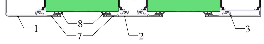
10 Table Technical data Model Box MD50 SD50 MD50+ SD50+ External sheet metal thickness and coating options Internal sheet metal thickness and coating options Base frame options 0.7mm Zn 0.7mm AluZn mm Zn different RAL powder coating 0.5mm Zn polyester painting RAL mm Zn 0.7mm AluZn mm Zn different RAL powder coating 0.8mm AISI mm AISI mm AISI mm AISI mm Zn polyester painting RAL mm Zn 0.5mm Zn 0.7mm Zn 0.5mm Zn 0.7mm AluZn mm AISI mm AluZn mm AISI mm AluZn mm AISI mm AISI mm AISI KR: 3mm galvanized steel 1-9KR: 3mm powder coated galvanized steel 1-9KR: 3mm powder coated galvanized steel 1-9KR: 3mm galvanized steel 1-9KR: 3mm powder coated galvanized steel 10-16KR: 4mm powder coated steel 0.5mm AluZn mm AISI KR: 3mm powder coated galvanized steel All AmberAir casing model boxes have rounded internal corners, which prevents accumulation of dust and dirt, facilitates cleaning and makes it possible to use in a hygienic unit design. It is possible to select different external and internal sheet metal materials for separate sections in the same AHU. AmberAir MD50+ and SD50+ have thermal bridging factor class TB1 it eliminates possibilities for condensate occurrence on outer surface of the unit. AmberAir MD50 and SD50 have thermal bridging factor class TB4 under certain ambient conditions condensate may occur on outer surface of the unit. Below illustrates AmberAir MD50, AmberAir SD50, AmberAir MD50+ and AmberAir SD50+ cross-sections. 10 IOM v2018.1


11 Figure AmberAir MD50 cross-section. 1 Corner profile, 2 intermediate profile, 3 special corner profile for connection between two sections, 4 double skin stone wool panel, 5 - rounded profile corners, 6 non-porous gasket fitted in special groove, 7 panel block aluminium profile, 8 panel block gasket Figure AmberAir SD50 cross-section. 1 Corner profile, 2 intermediate profile, 3 special corner profile for connection between two sections, 4 double skin polyurethane foam panel, 5 - rounded profile corners, 6 non-porous gasket fitted in special groove, 7 panel block aluminium profile, 8 panel block gasket IOM v


12 Figure AmberAir MD50+ cross-section. 1 Corner profile with thermal break strips, 2 intermediate profile with thermal break strips, 3 special corner profile with thermal break strips for connection between two sections, 4 double skin stone wool panel, 5 - rounded profile corners, 6 non-porous gasket fitted in special groove, 7 panel block aluminium profile, 8 panel block gasket Figure AmberAir SD50+ cross-section. 1 Corner profile with thermal break strips, 2 intermediate profile with thermal break strips, 3 special corner profile with thermal break strips for connection between two sections, 4 double skin polyurethane foam panel, 5 - rounded profile corners, 6 non-porous gasket fitted in special groove, 7 panel block aluminium profile, 8 panel block gasket 12 IOM v2018.1
13 Unit sections width and height depend on the unite size and don t depend on the casing model box type (see Table 5.2.4). The sections lengths depends on the specific components fitted into the section (eg. cooler, heater, fan, etc.). You will find the exact drawing of your purchased AHU in its Technical data sheet. Size Table Section sizes Width (mm) Height (mm) 1-KR KR KR KR KR KR KR KR KR KR KR KR KR KR KR KR IOM v
14 5.3. Outdoor design AmberAir air handling units are available in outdoor design. Units are equipped with roofs, outdoor grilles (option) and hood (option). They provide protection from rainy and snowy weather. All doors with hinges and handles are equipped with wind protection device to provide safe access to the unit in windy conditions. Inspection windows have covers to protect inner components from sunlight. Control section has integrated heater for its components. We recommend choosing powder coated external sheet metal for AmberAir MD50 and MD50+ outdoor unit s panels (corrosion protection class C3 according to EN ISO :1998). AmberAir SD50 and SD50+ panel s external sheet metal always has special polyester painting which comply with corrosion protection class C4 according to EN ISO : Hygienic design AmberAir MD50+ and SD50+ air handling units are available in hygienic design. These units has following features: - Level 1 or Level 2 HAHU. - Smooth internal surface prevents accumulation of dust and dirt, facilitates easy cleaning and disinfection of the unit. Joints between panels and frame profiles at the floor are sealed to create closed surface for Level 2 units. - Components of the unit are easy accessible for cleaning on the suction and pressure sides (via service sections) or quickly removable. - Only direct driven (plug) fans used, as they are easy to clean. - All non-metallic parts excluding paints but including sealants, gaskets, filters, etc. with surface in the air stream > 5 cm² comply with EN ISO 846. The maximum allowed growth rate for microorganisms according Table 4 and 5 of ISO 846 is 1. - All internal metallic surfaces are made from materials with minimum corrosion protection class C3 in accordance with EN ISO :1998 or from aluminium. - Stainless steel AISI 304 drip trays with slope towards a water drain. - Plate heat exchanger section with drip tray on supply air side and extract air side. - All door locks, handles and hinges are outside of the unit. - Blind rivets are used inside of the unit. - All sealing and gasket materials are closed cell structure (non-porous), abrasion resistant, emissions free and odourless. They do not absorb moisture and not provide a nutrient substrate for microorganisms. - Stone wool with glass fibre facing removable silencer s baffles. - All necessary requirement checked by selection software during unit design Side by side design AmberAir air handling units with cross flow, counter flow and rotary heat exchangers are available in side by side design. Plate heat exchangers is mounted horizontally, other supply and exhaust air sections are stacked in horizontal plane, not vertically as usual. Rotary heat exchanger is mounted vertically, other supply and exhaust air sections are stacked in horizontal plane, not vertically as usual. 14 IOM v2018.1
15 5.6. Design for coastal environment AmberAir design for coastal environment is dedicated to environment, which is considered at risk for chloride-related corrosion. Generally, locations within 9 to 18 km of salt water are considered at risk for chloride-related corrosion, but local weather patterns and the performance of metals near the site should be evaluated prior to environment selection in AHU selection software. AmberAir design for coastal environment has an increased corrosivity resistance with upgraded casing elements as follows: - Casing profile from anodized aluminium; - Internal and external metal surfaces complies with corrosivity category C4 requirements (EN ISO :1998) or from aluminium; - Drip trays are made of AISI 304 or AISI 316; - Plates of coils and heat exchangers are covered by epoxy coating Design for swimming pools AmberAir Pool air handling units are available in special design intended for use in swimming pools. These air handling units have been designed to create an ideal microclimate for indoor swimming pool premises. Depending on settings and air parameters, smart control automatically ensures air quality parameters by extracting excessive humidity, supplying fresh air, returning most of the extracted air heat, and maintaining the required temperature of supplied air. Main features: - Cross-flow or counter-flow heat exchangers, with or without heat pump; - Dampers are equipped with actuators designed for swimming pools (IP 66); - Special control programs for different swimming pool modes; - Casing profile from anodized aluminium; - Internal metal surfaces complies with corrosivity category C4 requirements (EN ISO :1998) or from aluminium; - Drip trays are made of AISI 304 or AISI 316. Refer to separate AmberAir Pool IOM for more information about control modes of AmberAir Pool air handling units. All other information from this manuals also applies for AmberAir Pool air handling units. IOM v
16 6. Components 6.1. Fans Direct-driven centrifugal fan Description: Direct-driven centrifugal fans (plug fans) with one of the following motor and impeller combination: AC motor with metal or plastic impeller, motor protection class IP 55; EC motor with metal or plastic impeller, motor protection class IP 54; EX motor with metal impeller, motor protection class IP 55; PM motor with metal impeller, motor protection class IP 54. Pressure gauge is available as option with special scale for airflow monitoring. Electrical connection: Electrical connection may only be undertaken by technically trained personnel. A lockable safety switch must be installed near the fan unit access door. Before making the electrical motor connections, compare the connection specifications with the specifications on the motor identification plate. For hygienic units with internal section height below 1.6m fan shall be removable. In case the unit ordered without electrical connection make electrical connection in such way that withdrawal of the fan can be performed by maintenance personal only, without the help of an electrician (No need to undo electrical connection, only mechanical disassembly and only opening of electrical socket is allowed). Observe the fan / motor manufacturer's operating instructions. Refer to separate Electrical installation, operation and maintenance manual document for more information. Setting up the unit: The fan should be checked for mechanical oscillations after installation. If the amount of fan oscillation is larger than 2.8 mm/s, (measured on the end plate of the impeller side of the motor bearing), the motor/impeller unit must be examined by specialists and, if necessary, rebalanced. Check the current consumption! Check the direction of rotation (the rotation direction arrow is on the impeller base plate or on the fan housing). Do not exceed the maximum operating speed. Speed controllable through a frequency converter. Do not exceed the maximum operating frequency. Maintenance and cleaning: WARNING! Before opening the door, the fan must be switched off, isolated and allowed to run down (at least two minutes). The fan should be checked for mechanical oscillations every 12 months. The maximum permissible oscillation intensity is 2.8 mm/s (measured at the motor-bearing impeller side). For all maintenance and cleaning work: - The fan impeller must be at a standstill! 16 IOM v2018.1
17 - Power supply is interrupted and secured against restoration! - Verify the absence of voltage! Observe the fan manufacturer s operation instructions. Observe the motor manufacturer's operating instructions. Check the impeller, in particular the weld-seams, for possible cracks. Flexible connection between fan and casing is to be checked every 1 month. Unsealed connection leads to breakdowns and danger from escaping transported medium and must be replaced. Regularly inspect and clean where necessary to prevent imbalance due to ingress of dirt. Clean the fan's flow area. Maintenance interval in accordance with the degree of contamination of the impeller (at least once in 6 months). You can clean the entire fan with a moist cloth. Do not use high-pressure cleaners. Do not use any aggressive, paint solvent cleaning agents when cleaning. Figure Direct-driven centrifugal fan section. 1 - Plug fan on anti-vibration mounts, 2 door with lockable handle, 3 inspection window (optional), 4 safety switch (optional). IOM v
18 Belt-driven centrifugal fans Description: Belt-driven centrifugal fans produced with forward curved or back curved impeller and AC motor. Motor protection class IP 55. Figure Belt-driven centrifugal fan section. 1 Belt-driven fan on anti-vibration mounts, 2 belts, 3 motor s pulley, 4 motor, 5 flexible connection, 6 fan s pulley, 7 belts tensioning mechanism. Electrical connection: Electrical connection may only be undertaken by technically trained personnel. A lockable safety switch must be installed near the fan unit access door. Before making the electrical motor connections, compare the connection specifications with the specifications on the motor identification plate. Observe the fan / motor manufacturer's operating instructions. Refer to separate Electrical installation, operation and maintenance manual document for more information. Setting up the unit: Check the current consumption! Check the direction of rotation of the impeller (the rotation direction indicated by arrow). Do not exceed the maximum operating speed. Check fan smooth running. There should be no unusual oscillation or vibration. After one hour of continuous run, stop the fan and check belt tensioning and, if necessary, retension the belts; after 3-4 days of operation check again the V-belt tension. Minimum test load (Fp, [N]) and belt displacement (E, [mm]) at minimum test load indicated in AHU s technical datasheet. 18 IOM v2018.1
19 Figure Belts tension check. Fp, [N] minimum test load, E, [mm] belt displacement. Bearings: Like all components, the bearings must be periodically checked and if required cleaned and re-lubricated. The base and R-version fans are supplied with pre-greased sealed for life ball bearings. These bearings guarantees a life of hours at peak performance. The maintenance of this type of bearing consists of cleaning its external surfaces and inspection to detect any possible abnormal operation or defective gaskets. If the latter is detected, the bearings have to be replaced. By changing the bearings it's necessary to change the rubber too. The T-version fans are supplied with re-greasable ball bearings with plummer block. The TZAF T2, TZAF FF T2, NTHZ T2 fans from size 560 are supplied with splitted housing ball or roller bearing type. These bearings are regreasable and we recommend to substitute completely the grease after 2 re-lubrications. Refer to fan manufacturer s operating instruction for detailed information. Maintenance and cleaning: WARNING! Before opening the door, the fan must be switched off, isolated and allowed to run down (at least two minutes). It's recommended to check every 1 month the belt tension and the alignment of the V-belts. Tension the belts when they are vibrating, loose or when belts are changed. Check the alignment of the wheel against the shaft and the conditions of the fixing bolts. If one belt is broken off it is necessary to substitute the whole set of bells. Flexible connection between fan and casing parts is to be checked every 1 month. Unsealed connection leads to breakdowns and danger from escaping transported medium and must be replaced. Observe the fan manufacturer s operation instructions. Observe the motor manufacturer's operating instructions. Regularly inspect and clean where necessary to prevent imbalance due to ingress of dirt. Clean the fan's flow area. Maintenance interval in accordance with the degree of contamination of the impeller (at least once in 6 months). You can clean the entire fan with a moist cloth. Do not use high pressure cleaners. Do not use any aggressive, paint solvent cleaning agents when cleaning IOM v
20 6.2. Heat recovery systems Counter-flow plate heat exchanger Description: In the counter-flow plate heat exchanger, the warm extract air and the cool fresh air, separated by thin plates, pass each other in counter-flow. No mixing of the two air streams takes place. Therefore, the transmission of dirt, odours, moisture, bacteria, etc. is impossible. Heat transmitted from extract air to fresh air purely by conduction because of the temperature difference between the two air streams: the warm extract air cooled down and the cool fresh air heated up. Counter-flow plate heat exchanger section divided in separate parts from size 12-KR (double deck) or 4-KR (side by side) due transportation reasons. Refer to separate assembly manual for assembly of such section. Types: Counter-flow plate heat exchanger double deck; Counter-flow plate heat exchanger side by side. Standard plate heat exchangers assembly components: Aluminium plate heat exchanger; Stainless steel drip tray on extract air side; By-pass damper for performance control and freezing prevention. Optional components: Droplet eliminator (stainless steel frame, plastic profile) on extract air side; Stainless steel drip tray on supply air side. Electrical connection: Electrical connection may only be undertaken by technically trained personnel. A lockable safety switch must be installed near the fan unit access door. Refer to separate Electrical installation, operation and maintenance manual for by-pass valve actuator connection. Maintenance: Check if gaps between the heat exchangers plates are not contaminated. Clean if necessary. Check the drainage system (see Drainage system). Regular check if drip tray 8 is tight. Clean drip tray and drain piping. Check if bypass damper works properly. Check if the heat exchanger's sealing elements are not harmed (sealant, sealant strips). Repair if necessary. Cleaning: Cleaning sequence when the heat exchanger is in section: - Clean dust with soft brush; - Blow out dirt with the blower. 20 IOM v2018.1
21 Cleaning sequence when heat exchanger is pulled out: - The heat exchanger is cleaned with tepid water and alkaline mixture which makes no corrosion to aluminium; - Do not use direct water flow or water blowers. It can spoil heat exchanger. - Put the heat exchanger back after cleaning. - Seal it hermetically; otherwise, the heat exchanger will not work properly! Dismantling: Release panel blocks 2; Take off service door 1, panels 3 and aluminium profiles 4; Open quick-release mechanism 9; Unscrew screws to unfasten the by-pass damper 6 Pull out by-pass damper 6, by-pass chamber 5 and heat exchanger 7; Do not damage sealing strips while withdrawing the heat exchanger. If sealing strips are damaged change them with new ones; The heat exchanger is mounted conversely to dismantlement sequence. Be sure that the heat exchanger installed hermetically. Important: Do not damage the heat exchanger's plates while mounting it into section. Do not use the heat exchanger without filter in air handling unit! Filter must be installed before heat exchanger both in supply and in exhaust airflow. Figure Counter-flow heat exchanger section. 1 Service door, 2 panel blocks, 3 removable panels, 4 aluminium profiles. IOM v
22 Figure Counter-flow heat exchanger section. 5 By-pass chamber, 6 by-pass damper, 7 heat exchanger, 8 condensate tray, 9 quickrelease mechanism Cross-flow plate heat exchanger Description: In the plate heat exchanger, the warm extract air and the cool fresh air, separated by thin plates, pass each other in cross-flow. No mixing of the two air streams takes place. Therefore, the transmission of dirt, odours, moisture, bacteria, etc. is impossible. Heat transmitted from extract air to fresh air purely by conduction because of the temperature difference between the two air streams: the warm extract air cooled down and the cool fresh air heated up. Cross-flow heat exchanger section divided in separate parts from size 12-KR (double deck) or 4-KR (side by side) due transportation reasons. Refer to separate assembly manual for assembly of such section. Types: Crossflow plate heat exchanger double deck; Crossflow plate heat exchanger side by side. Standard plate heat exchangers assembly components: Aluminium plate heat exchanger; Stainless steel drip tray on extract air side; By-pass damper for performance control and freezing prevention. Optional components: Epoxy coated plate heat exchanger; 22 IOM v2018.1
23 Droplet eliminator (stainless steel frame, plastic profile) on extract air side; Stainless steel drip tray on supply air side. Electrical connection: Electrical connection may only be undertaken by technically trained personnel. Refer to separate Electrical installation, operation and maintenance manual for by-pass valve actuator connection. Maintenance: Check if gaps between the heat exchangers plates are not contaminated. Clean if necessary. Check the drainage system (see Drainage system). Regular check if drip tray 8 is tight. Clean drip train and drain piping. Check if bypass damper works properly. Check if the heat exchanger's sealing elements are not harmed (sealant, sealant strips). Repair if necessary. Cleaning: Cleaning sequence when the heat exchanger is in section: - Clean dust with soft brush; - Blow out dirt with the blower. Cleaning sequence when heat exchanger is pulled out: - The heat exchanger is cleaned with tepid water and alkaline mixture which makes no corrosion to aluminium; - Do not use direct water flow or water blowers. It can spoil heat exchanger. - Put the heat exchanger back after cleaning. - Seal it hermetically; otherwise, the heat exchanger will not work properly! Dismantling: Release panel blocks 4; Take off service door 1, panels 2 and aluminium profiles 3; Release fixing bolts 9; The heat exchanger 5 is pulled out together with bypass damper 6 and by-pass chamber 7; Do not damage sealing strips while withdrawing the heat exchanger. If sealing strips are damaged change them with new ones; Unscrew screws to unfasten the by-pass damper 6. The heat exchanger is mounted conversely to dismantlement sequence. Be sure that the heat exchanger installed hermetically. Important: Do not damage the heat exchanger's plates while mounting it into section. Do not use the heat exchanger without filter in air handling unit! Filter must be installed before heat exchanger both in supply and in exhaust airflow. IOM v
24 Figure Cross-flow heat exchanger section. 1 Service door, 2 removable panels, 3 aluminium profiles, 4 panel blocks. Figure Cross-flow heat exchanger section. 5 Heat exchanger, 6 by-pass damper, 7 by-pass chamber, 8 condensate tray, 9 fixing bolts. 24 IOM v2018.1
25 Rotary heat exchanger Description: Rotary heat exchangers are regenerators with rotating heat accumulators. The heatdissipating and heat-absorbing air flows heat or cool the rotating, air-permeable storage accumulator. Depending on the air conditions and the surface of the accumulator material, moisture may also be transferred in the process. Self-cleaning effect due counter-flow supply. Double deck arrangement. Rotary heat exchanger section can be divided in separate parts from size 12-KR (double deck) or 11-KR (side by side) due transportation reasons. Refer to separate assembly manual for assembly of such section. Rotary heat exchanger itself divided in separate parts from wheel diameter 2690mm. Refer to separate assembly manual for assembly of such heat exchanger. Types: Rotary heat exchanger double deck; Rotary heat exchanger side by side. Material types: Condensation - cost-efficient solution to recover sensible heat; Condensation, epoxy coating solution to recover sensible heat for applications with request of increased corrosion resistance; Condensation, aluminium alloy solution to recover sensible heat for industrial applications with request of increased corrosion resistance; Enthalpy, hybrid - cost-efficient solution to recover sensible heat and transfer latent heat; Sorption (molecular sieve 3Å) - solution to recover sensible heat and latent heat to a very high degree. Electrical connection: Electrical connection may only be undertaken by technically trained personnel. Rotors equipped with 1-phase motor (w/o control), 3-phase motor (w/o control) or stepping motor with controller. Refer to separate Electrical installation, operation and maintenance manual document for motor and controller connection. Do not route the wires through the heat exchanger s casing. Otherwise it will be impossible to pull out heat exchanger in case the maintenance needed without help of electrician. Maintenance: Check if the heat exchangers gaps are not contaminated. Clean if necessary. Check if sealing brushes of the rotary heat exchanger work properly. Readjust or replace if necessary. The brush sealing are easily adjusted by loosening the screws and moving the brush sealing into the right position. Check if driving gear of the rotary heat exchanger works properly. Check if the heat exchanger's sealing elements are not harmed (sealant, sealing strips). Repair if necessary. IOM v
26 Cleaning: Cleaning sequence when heat exchanger is in section: - Clean dust with soft brush; - Dirt can be cleaned out with blower slowly turning the rotor. Cleaning sequence when heat exchanger is pulled out: - Heat exchanger is cleaned with tepid water and alkaline mixture which makes no corrosion to aluminium; - Do not use direct water flow or water blowers. It can spoil heat exchanger. - Put the heat exchanger back after cleaning. - Seal it hermetically; otherwise, the heat exchanger will not work properly! Dismantling: Release panel blocks 1. Take off panel 2. Unscrew screws and disengage fastening elements 3. Take out rotary heat exchanger with casing 4. Take off driving gear, unscrew axis and fastening bolts in case of rotary heat exchanger 5 extraction. The heat exchanger is mounted conversely to dismantlement sequence. Be sure that the heat exchanger is installed hermetically. Important: Some rotary heat exchangers are delivered with rubber transportation locks 6 which prevent rotor wheel from deformation. These rotary heat exchangers are marked with special warning label on the section. Remove rubber transportation locks before connecting rotary heat exchanger section to other section of the AHU otherwise the unit will not work properly. Do not damage the heat exchanger s foil while mounting it into section. Do not use the heat exchanger without filter in air handling unit! Filter must be installed before heat exchanger both in supply and in exhaust airflow. 26 IOM v2018.1
27 Figure Rotary heat exchanger section. 1 Panel blocks, 2 removable panel, 3 fastening elements, 4 casing, 5 rotary heat exchanger, 6 - rubber transportation locks Run around coils Description: Run around coils system consists of one or several supply air and extract air coils in which a brine solution circulated to recover heat energy from the extract air. The airflows not mixed, so there is no contamination of the fresh air by the exhaust airflow. Technical data: Normal air velocity 2-3m/s. Max air velocity 5.0 m/s. Max permissible operating pressure: 1.6 MPa at a max permissible operating temperature of 100 C. Max permissible operating pressure: 1.0 MPa at a max permissible operating temperature of 150 C. The coils consist of copper tubes and aluminium, AlMg 2.5 or epoxy coated aluminium fins. The casing is made of hot galvanized steel sheet, AluZn 185 steel sheet, aluminium, AISI 304 or AISI 316. IOM v
28 The coil header can be equipped with nipples for bleeding and draining (depends on coil supplier) and at least one of the nipples can be equipped with extension nipple for a freeze protection thermostat (see Figure and Figure ). Extension nipple does not available for water connection size DN 15. Extract air coil with stainless steel drip tray and droplet eliminator (stainless steel frame, plastic profile). Droplet eliminator always included if air speed through coils from 2,5m/s (aluminium fins) or from 1,6m/s (epoxy coated fins). Optional for lower speeds. All the connections are fitted with male pipe threads (SS-EN ISO 228-1). Coils sections provided without circulation pump and mixing valve. Refer to pump provider documentation for pump connection. Figure Run around coils section. 1 Extract air coil section; 2 supply air coil section; 3, 6 liquid inlet; 4, 5 liquid outlet, 7 airflow direction. Maintenance and cleaning, dismantling: Refer to section Water heater for supply air coil. Refer to section Water cooler for extract air coil. 28 IOM v2018.1
.")
29 Rotary heat exchanger with heat pump section Description: Rotary heat exchanger with heat pump is a separate section, containing complete standalone reversible heat pump system (heating and cooling). The refrigerant is evaporated and condensed directly in the integrated batteries and the capacity controlled automatically. Rotary heat exchanger with heat pump section for big sizes of air handling unit could be divided in separate parts. Refer to separate assembly manual for assembly of such section. Technical data: Refer to separate Rotary heat exchanger with heat pump installation, operation and maintenance manual. Maintenance and cleaning, dismantling: Refer to section Rotary heat exchanger for rotary heat exchanger. Refer to section DX cooler for coils. Figure Rotary heat exchanger with heat pump section. 1 removable panel of DX cooler/heater section, 2 service door of empty section, 3 condensate tray, 4 heat pump, 5 rotary heat exchanger, 6 droplet eliminator, 7 panel blocks, 8 removable panel of rotary heat exchanger section, 9 controls. IOM v
30 Drainage system Description: When plate heat exchangers or coolers are used in ventilation system the drainage system must be mounted. Drainage system consists of drip trays (mounted into air handling unit), siphons, pipes, valves. Construction and requirements to siphon: Siphon is the main element in the system. It can be made from metal, plastic. Siphon must be made from corrosion resistant material. It is desirable that siphon should be made from transparent material (it is the best way to see if siphon is filled with water or not). The height of the syphon must be set in accordance with the under pressure or overpressure of ventilation unit so that suction or blowing out of the air in relation to connected waste water pipe is prevented. The water must flow directly from the syphon into a catch pit or funnel. Inner radius of siphon must be the same size as drainage connection tube s (drainage outlet tube of drip tray). Drip trays equipped with pipes Ø40mm. Calculation of siphon trap (see Figure ): The height of the siphon is determined as follows: 1. Under (negative) pressure in the section: H (mm) = 85, mm Where p = pressure in the section in Pa (positive value). In case p < 500 Pa use 500 Pa for calculation. 2. Over pressure (positive) in the section: H (mm) =. 115, mm Where p = pressure in the section in Pa. In case p < 500 Pa use 500 Pa for calculation. 3. A clear space of at least Xmin = H - 85, mm is required below the bottom of the unit section for the water trap. Important: 1. Siphon and pipes must be heated with an electric thermal cable for outdoor units (this will prevent freezing of drainage system at negative ambient temperatures). Additionally siphon and pipes should be thermal insulated with an insulating material. 2. Fill siphon with water before start-up of the unit. 30 IOM v2018.1
31 A B Figure Height of syphon trap. A - Height of ball syphon for negative pressure, B height of syphon for positive pressure. IOM v
32 Construction and requirements to drainage system: The air handling unit may have different number of drip trays. It depends on its components. Sections with drip tray: plate heat exchanger section, water cooler section, DX cooler section, heat recovery coil's exhaust air section. The main requirement to drainage system is that every drainage connection tube (drainage outlet tube of drip tray) should be connected to separate siphons. Do not install positive or negative pressure siphon trap to the same drain pipe. Do not under any circumstances connect the syphon directly to the sewage network. Drain pipes shall have a slope of at least 2⁰ towards the drain. To avoid flowing of water from one unit s side to other side (because of pressure difference) mount tubes of equal diameters, ensure that drainage system is mounted tightly and diameter of connection tubes should be of the same diameter as drainage connection tubes (drainage outlet tube of drip tray). Siphons must be always filled with water. If siphon is not filled with water it cannot carry out its function and premises can be dousing with water. Check tightness of drainage system each 3 months. Important: The water trap and discharge pipe must not be subjected to temperatures below freezing. If the unit is installed outdoors, the drain pipe, water trap and discharge pipe must be insulated. The water trap should not be exposed to direct sunlight Plate heat exchanger with heat pump section Description: Plate heat exchanger (cross-flow or counter-flow) with heat pump is a separate section, containing complete stand-alone heat pump system (heating). The refrigerant is evaporated and condensed directly in the integrated batteries and the capacity controlled automatically. This section can be selected for AmberAir Pool air handling units. Plate heat exchanger with heat pump section for big sizes of air handling unit could be divided in separate parts. Refer to separate assembly manual for assembly of such section. Technical data: Refer to separate AmberAir Pool IOM. Maintenance and cleaning, dismantling: Refer to section Counter-flow plate heat exchanger for counter-flow plate heat exchanger. Refer to section Cross-flow plate heat exchanger for cross-flow plate heat exchanger. Refer to section DX cooler for coils. 32 IOM v2018.1
33 Figure Plate heat exchanger with heat pump section. 1 Removable panel of DX cooler/heater section, 2 service door of empty section, 3 condensate tray, 4 heat pump, 5 service door of plate heat exchanger, 6 droplet eliminator, 7 panel blocks, 8 removable panel of plate heat exchanger section Cross-Flow section Description: Cross-flow section is used to change air flow directions before or after cross-flow, counterflow and rotary heat exchanger. IOM v
34 1 Removable panel, 2 panel blocks, 3 airflow guide, 4, 5 airflow direction. unit Heat exchangers Water heater Description: The water heaters designed for heating air with fluid as the heat carrier and mounted in the Technical data: Normal air velocity 2-4m/s. Max permissible air velocity 5m/s. Max permissible operating pressure: 1.6MPa at a max permissible operating temperature of 100 C. Max permissible operating pressure: 1.0MPa at a max permissible operating temperature of 150 C. The coil consist of copper tubes and aluminium or epoxy coated aluminium fins. The casing is made of hot galvanized steel sheet or AluZn 185 steel sheet. Other materials on request. The coil header can be equipped with nipples for bleeding and draining (depends on heater supplier) and at least one of the nipples can be equipped with extension nipple for a freeze protection thermostat (see Figure and Figure ). Extension nipple does not available for water connection size DN 15. All the connections are fitted with male pipe threads (SS-EN ISO 228-1). 34 IOM v2018.1
35 Water heater sections can be supplied with heat carrier temperature control point RMG. Refer to separate Electrical installation, operation and maintenance manual document for RMG connection. Maintenance and cleaning: Regularly check if the heater is not contaminated or spoiled. The system must be adequately vented to provide correct performance. To remove air from the water heater use air bleed nipple 2. Optional manual bleed valve or automatic bleed valve available on request (see Figure and Figure ). Bleed valve can be connected to nipple for bleeding or directly to main liquid tube (depends on heater supplier). Water connection system must be tight. If heater is contaminated, clean it with brush, vacuum cleaner or with direct air stream. In more difficult situation, clean grime using tepid water and alkaline mixture, which does not generate corrosion to aluminium. If the heating surfaces coated with greasy dust, first spray the entire heater with environmentally compatible solvent under low pressure. Then clean the heater with water using a high-pressure jet after minutes. It is important to hold the nozzle perpendicular to the fins and not closer than 150mm to prevent damaging the fins. Use a fin comb to straighten any deformed fins. When installing air heaters that use hot water or steam as a heating medium, great care should be exercised when opening air vents and gate valves in the system. Failure to do this may result in serious damage through water hammering or a discharge of steam. To avoid burns, do not touch hot surfaces. Dismantling: Whenever a heater is to be dismantled and removed from a system, it is important that the heater be emptied of liquid (use liquid drain pipe 3). If freezing is likely to occur in the heater after it has been drained of liquid, it should be blown with compressed air to ensure that all water is gone. Release panel blocks 4. Take off panel 5 together with sealing ring s covers 9 and sealing rings 6 itself. Unscrew screws and disengage fastening elements 7 presented at the bottom and at the top. Take out the heater 8. The water heater mounted conversely to dismantlement sequence. Ensure tightness between heater casing and frame construction, tubes and protection cover after mounting. Protect connection tubes and aluminium fins from deformation while mounting heater into the air handling unit. Make sure that airflow does not get into header of coil when heater is mounted. Important: If chloride content of process water is above 120-ppm (120mg/l) supplier is not responsible for corrosion occurred in such conditions. The coils shall be connected to obtain a counter-flow mode, i.e. air and water must flow against each other, see Figure and Figure Section provided with labels that indicate how the inlet and the return piping is to be connected. IOM v
.")
36 Figure Water heater section. 1 Water inlet/outlet, 2 nipple for bleeding, 3 nipple for draining, 4 panel blocks, 5 removable panel, 6 sealing ring, 7 fastening element, 8 heating coil, 9 sealing ring s cover. Figure Coil counter-flow coupling (single liquid inlet and outlet). A Right-hand maintenance; B left-hand maintenance; 1 liquid in; 2 liquid out; 3 airflow direction. 36 IOM v2018.1
37 Figure Coil counter-flow coupling (multiple liquid inlets and outlets). A Right-hand maintenance; B left-hand maintenance; 1 liquid in; 2 liquid out; 3 airflow direction. a) b) c) IOM v


. Figure 6.")


38 d) e) Figure Water coils accessories. a nipple H-A01, b manual bleed valve H-A02, c automatic bleed valve with nonreturn valve H-A03, d manual bleed valve H-A04 (direct connection to main liquid tube), c automatic bleed valve with non-return valve H-A05 (direct connection to main liquid tube). Figure Bleed valve and nipple installation. 1 Nipple for bleeding, 2 Automatic bleed valve with non-return valve, 3 Manual bleed valve. 38 IOM v2018.1
39 unit Water cooler Description: The water cooler designed for cooling air with fluid as the heat carrier and mounted in the Technical data: Normal air velocity 2-3m/s. Max permissible air velocity 5m/s. Max permissible operating pressure: 1.6MPa at a max permissible operating temperature of 100 C. Max permissible operating pressure: 1MPa at a max permissible operating temperature of 150 C. The coil consist of copper tubes and aluminium or epoxy coated aluminium. The casing is made of hot galvanized steel sheet or AluZn 185 steel sheet. Other materials on request. The coil header can be equipped with nipples for bleeding and draining (depends on cooler supplier) and at least one of the nipples can be equipped with extension nipple for a freeze protection thermostat (see Figure and Figure ). Extension nipple does not available for water connection size DN 15. All the connections are fitted with male pipe threads (SS-EN ISO 228-1). Section supplied with stainless steel drip tray and droplet eliminator (stainless steel frame, plastic profile). Droplet eliminator always included if air speed through coils from 2,5m/s (aluminium fins) or from 1,6m/s (epoxy coated fins). Optional for lower speeds. Water heater sections can be supplied with heat carrier temperature control point RMG. Refer to separate Electrical installation, operation and maintenance manual document for RMG connection. Maintenance and cleaning: Regularly check if cooler is not contaminated or spoiled. The system must be adequately vented to provide correct performance. To remove air from the water cooler use the air bleed nipple 2. Optional manual bleed valve or automatic bleed valve available on request (see Figure and Figure ). Bleed valve can be connected to nipple for bleeding or directly to main liquid tube (depends on cooler supplier). Water connection system must be tight. Check the drainage system (see Drainage system).). Regularly check if drip tray 9 is tight. Clean drip train and drain piping. If cooler is contaminated, clean it with brush, vacuum cleaner or with direct air stream. In more difficult situation, clean grime using tepid water and alkaline mixture, which does not generate corrosion to aluminium. If the cooling surfaces coated with greasy dust, first spray the entire cooler with environmentally compatible solvent under low pressure. Then clean the cooler with water using a high-pressure jet after minutes. It is important to hold the nozzle perpendicular to the fins and not closer than 150mm to prevent damaging the fins. Use a fin comb to straighten any deformed fins. If droplet eliminator is contaminated, clean it. IOM v

40 Dismantling: Whenever a cooler is to be dismantled and removed from a system, it is important that the cooler be emptied of liquid (use liquid drain pipe 3). If freezing is likely to occur in the cooler after it has been drained of liquid, it should be blown with compressed air to ensure that all water is gone. Release panel blocks 4. Take off panels 5 together with sealing ring s covers 11 and sealing rings 6 itself. Unscrew screws and disengage fastening elements 7 presented at the bottom and at the top. Take out the cooler 8 and droplet eliminator 10. The water cooler is mounted conversely to dismantlement sequence. Ensure tightness between cooler casing and frame construction, tubes and protection cover after mounting. Protect connection tubes and aluminium fins from deformation while mounting cooler into the air handling unit. Make sure that airflow does not get into header of coil when coil is mounted. Important: If chloride content of process water is above 120-ppm (120mg/l) supplier is not responsible for corrosion occurred in such conditions. The coils shall be connected to obtain a counter-flow mode, i.e. air and water must flow against each other, see Figure and Figure Section provided with labels that indicate how the inlet and the return piping is to be connected. Figure Water cooler section. 1 water inlet/outlet, 2 nipple for bleeding, 3 nipple for draining, 4 panel blocks, 5 removable panel, 6 sealing ring, 7 fastening element, 8 cooling coil, 9 drip tray, 10 droplet eliminator, 11 sealing ring s cover. 40 IOM v2018.1

41 unit DX cooler Description: The DX cooler designed for cooling air with an evaporating medium and mounted in the Technical data: Normal air velocity 2-3m/s. Max permissible air velocity 5m/s. Depending on refrigerant type and evaporating temperature DX coolers available with max permissible operating pressure 2.2MPa, 2.9MPa or 4.3MPa at a max permissible operating temperature of 100 C. Do not exceed permissible pressure range. The coil consist of copper tubes and aluminium or epoxy coated aluminium. The casing is made of hot galvanized steel sheet or AluZn 185 steel sheet. Other materials on request. For utmost cleanness, the coils are inert gas soldered and filled with nitrogen prior to delivery. Section with stainless steel drip tray and droplet eliminator (stainless steel frame, plastic profile). Droplet eliminator always included if air speed through coils from 2,5m/s (aluminium fins) or from 1,6m/s (epoxy coated fins). Optional for lower speeds. Output stages: DX coolers can be delivered divided into one, two or several output stages depending on the height of the heat exchanger. First tube in airstream is always refrigerant OUT tube and the second tube is refrigerant IN tube for one stage cooler. DX coolers with two output stages are normally coupled so that every other coil is coupled to output stage 1 and every other to output stage 2 ("interlaced coupling"), see Figure Connections and fluid pipes are equipped with copper washers that indicate the stage association. DX coolers with three or more output stages are normally divided vertically, see Figure Figure Two output stages with "interlace coupling. a Expansion valve (not included), b soldered copper washer, c air direction, d refrigerant IN, e refrigerant OUT. IOM v
. In this case used special three-pipe coil.")
42 Figure Three or more output stages are normally divided vertically. a Expansion valve (not included), b soldered copper washer, c air direction. Maintenance and cleaning: Refer to section Water cooler. Heating Mode: DX cooler can work either in heating mode (optional checkbox in selection software). In this case used special three-pipe coil. Possible connection to system for cooling mode shown in Figure and for heating mode shown in Figure Figure Reversible refrigerant flow, three-pipe coil, cooling mode. 1 Evaporator (cooling mode), 2 outside unit, 3 check valve, 4 refrigerant flow (out of the coil), 5 refrigerant flow (into the coil), 6 airflow direction 42 IOM v2018.1
43 Figure Reversible refrigerant flow, three-pipe coil, heating mode. 1 Condenser (heating mode), 2 outside unit, 3 check valve, 4 refrigerant flow (out of the coil), 5 refrigerant flow (into the coil), 6 airflow direction Dismantling: Whenever a cooler is to be dismantled and removed from a system, it is important to stop refrigerant supply to cooler (close shut-off valves before cooler). Release panel blocks 2. Take off panels 3 together with sealing ring s covers 9 and sealing rings 4 itself. Unscrew screws and disengage fastening elements 5 presented at the bottom and at the top. Take out the cooler 6 and droplet eliminator 8. DX cooler is mounted conversely to dismantlement sequence. After mounting there should be ensure tightness between cooler casing and frame construction, tubes and protection cover. Protect connection tubes and aluminium fins from deformation while mounting cooler into the air handling unit. Make sure that airflow does not get into header of coil when coil is mounted. IOM v

44 Figure DX cooler section. 1 Refrigerant inlet/outlet, 2 panel blocks, 3 removable panel, 4 sealing ring, 5 fastening elements, 6 DX cooler, 7 condensate tray, 8 droplet separator, 9 sealing ring s cover Electrical heater Description: The electrical heaters designed for heating air by converting electrical energy to heat and mounted in the unit. Technical data: The casing is made of Aluzinc steel sheet. Stainless steel heating elements. Two-stage overheat protection. Overheat protection used to protect heater from overheating if airflow is too slow or system is breakdown. First stage (automatic) overheat protection activates at 50 C and reverses automatically when it cools down. Second stage (manual) overheat protection activates at 100 C, it should be resettled manually by pressing "RESET" switch (-s). Connection to mains power: Electrical connection may only be undertaken by technically trained personnel. Electrical heaters should be connected to the standard mains power: three phase 230V / 50Hz or three phases 400V / 50 Hz. Wiring diagram is located on the inner side of the cover of electrical heater. Heater should be connected to the mains supply with stationary cable that carried out thought rubber ledge. 44 IOM v2018.1
45 Construction of power supply should be made so that voltage is supplied firstly to the fan and then to the electrical heater. Construction of power disconnecting should be so that voltage is disabled firstly from the electrical heater and then from the fan. Refer to separate Electrical installation, operation and maintenance manual document for more information. Installation: Distance from electrical heater and metallic or combustible materials should be not less than 100mm. Distance from elbows, dampers must be not less than double diagonal of heater. Otherwise the airflow will not be even and the overheat protection may be activated. Maintenance and cleaning: If heater is contaminated, clean it with brush, vacuum cleaner or with direct air stream. Dismantling: Whenever a heater is to be dismantled and removed from a system, firstly disconnect it from main power supply. Release panel blocks 1 and take off panel 2. Unscrew and take off electrical heater cover 3. Disconnect lead from electrical heater terminal box. Take out the heater 5. The electrical heater mounted conversely to dismantlement sequence. IOM v

46 Figure Electric heater section. 1 Panel blocks, 2 removable panel, 3 electrical heater cover, 4 reset button (-s), 5 electrical heater. Overheat protection: If overheat protection activates: Disconnect heater from the mains supply. Analyse and eliminate reasons of activation overheat protections thoroughly. When failures are eliminated, restore manual overheat protection, i.e. push "RESET" switch (-s) 4. For this purpose release panel blocks 1 and take off panel 2. Check if the heater works properly (no overheating). Establishment of malfunctions: Malfunction Reason of malfunction Eliminating malfunction Full heating no regulation No heating Malfunction is in electrical circuit up to heater (controller, thermostat). If there is no voltage on the contacts of heater then malfunction in electrical circuit up to heater (controller, fuses, thermostats, switches, etc.). If there is voltage on the contacts of heater then malfunction in overheat protections, heating elements. Check control devices and eliminate malfunction. Check control devices and eliminate malfunction. Check contacts of overheat protections, measure voltage on heating elements and eliminate malfunction. 46 IOM v2018.1

 content must not exceed 0.01 mg/kg. Ammonia content (NH3) must not exceed 0.3 mg/kg.")
47 Steam heater Description: The steam heater designed to heat air with steam and mounted in the unit. Technical data: Normal air velocity 2-4m/s. Max permissible air velocity 5m/s. Max permissible operating pressure: 1MPa at a max permissible operating temperature of 185 C. The coil consist of copper tubes and aluminium fins. The casing is made of hot galvanized steel sheet or AluZn 185 steel sheet. Other materials on request. All the connections are fitted with male pipe threads (SS-EN ISO 228-1). Important: The steam s ph-value should be between 8.8 and 9.2. The oxygen (O2) content must not exceed 0.01 mg/kg. Ammonia content (NH3) must not exceed 0.3 mg/kg. Connect coil with steam to the upper pipe and the return to the lower pipe (Figure ). Maintenance and cleaning, dismantling: Refer to section Water heater. Figure Steam heater. 1 Supply pipe, 2 vertical steam transfer, 3 return pipe. IOM v
48 unit Gas-fired heater Description: The gas-fired heater designed to heat air with natural or propane gas and mounted in the Technical data: 1. Nominal heating output from 11 to 200 kw for single units, up to 600 kw for multiple units. 2. Models available for indoor or outdoor applications. 3. Controls type: 10V modulating. 4. Tubes of the heat exchanger are made of stainless steel or aluminized steel. 5. Natural gas consumption from 2.1 to 28.7 m 3 /h, LPG consumption from 1,57 to 21,12 kg/h. 6. Airflow range from 1465 to m 3 /h. 7. Heating efficiency up to 91%. Maintenance and cleaning: 1. If heater is contaminated, clean it with brush, vacuum cleaner or with direct air stream. 2. Observe the gas-fired heater manufacturer's operating instructions. Dismantling: 1. Whenever a heater is to be dismantled and removed from a system, firstly disconnect it from power supply, gas supply 3, flue outlet 5 and combustion air inlet 4 (for indoor version). 2. Release panel blocks Take off panel (-s) 5 and aluminium profiles Release fastening elements Take out the heater The gas-fired heater mounted conversely to dismantlement sequence. 48 IOM v2018.1
49 Figure Gas-fired heater section, indoor version. 1 Panel blocks, 2 gas-fired heater, 3 gas inlet, 4 combustion air inlet, 5 removable panels, 6 flue outlet, 7 aluminium profiles, 8 fastening elements. Note: Gas inlet pipe 3, combustion air inlet pipe 4 and flue outlet pipe 6 are not provided for indoor version. Figure Gas-fired heater section, outdoor version. 1 Panel blocks, 2 gas-fired heater, 3 gas inlet, 4 combustion air inlet, 5 removable panels, 6 flue outlet, 7 aluminium profiles, 8 fastening elements. Note: Gas inlet pipe 3 is not provided for outdoor version. IOM v
50 6.4. Air filters Description: The air filters in a ventilation system prevent dust and other impurities reaching the premises. They also protect sensitive components in the air handling unit, such as air heaters, coolers and heat exchangers from contamination. The air filters usually shipped loose, packed in foil or in boxes, inside the air handling unit. It is essential to install air filters before putting the unit into operation, thus making sure sensitive components and ductwork are protected and kept clean. Changing of filter should be primarily based on clogging, indicated by final pressure drop. However, for hygienic reasons, filters in the first filter section should not be in use for more than one year. Filters used in a second or third section, should not be in use for more than two years. When dry conditions in all filter sections are guaranteed at all times, longer period of use are possible if the pressure drop remains below the defined maximum. Both visual inspection and monitoring of pressure drop is recommended (refer to section Filter contamination control accessories). A maximum of 90% RH is allowed before each filter section for hygienic units Panel filter Description: Panel filter with galvanized steel sheet or AluZn 185, AISI 304 or AISI 316 steel sheet frame and G4 filtration class synthetic media. Pre filter for comfort air conditioning applications. Slide type filter rack made of galvanized steel sheet, AluZn 185 steel sheet, AISI 304 steel sheet or AISI 316 steel sheet. Temperature resistant up to 110 C. Maintenance: Panel filter designed for one-time use. Replace clogged filter with the new one of the same quality and dimensions as the original. Replace filter when the pressure loss reaches the specified final pressure loss. Timely filter replacement ensures energy efficiency of the unit. Maintenance interval in accordance with the degree of contamination of the filters (at least 3 months). Keep at least one set of replacement filters in stock. Store in a dry and dust free area. Avoid contamination and damage. Replacement: Stop the AHU before filter replacement. This will prevent the penetration of any dust into the ventilation system falling from filter during replacement. Use particulate respirator during replacement. Release panel blocks 3. Take off panel 1. Take out filter 2. Vacuum clean the inner surfaces of the filter section and/or wipe it clean with a damp cloth. Insert new filters, set back panel 1 and fix it. 50 IOM v2018.1
51 Figure Panel filter section. 1 Removable panel, 2 panel filter, 3 - panel blocks Pocket filter Description: 1. Pocket filter with AluZn 185 steel sheet or plastic frame and M5, F7 or F9 filtration class synthetic media. Main filter for comfort air conditioning applications. 2. Slide type filter rack made of galvanized steel sheet, AluZn 185 steel sheet, AISI 304 steel sheet or AISI 316 steel sheet. 3. Temperature resistant M5 up to 110 C, F7 and F9 up to 80 C. 4. Drip tray available as option. Maintenance: Pocket filter designed for one-time use. Replace clogged filter with the new one of the same quality and dimensions as the original. Replace filter when the pressure loss reaches the specified final pressure loss. Timely filter replacement ensures energy efficiency of the unit. Maintenance interval in accordance with the degree of contamination of the filters (at least 3 months). Keep at least one set of replacement filters in stock. Store in a dry and dust free area. Avoid contamination and damage. IOM v
52 Replacement: Stop the AHU before filter replacement. This will prevent the penetration of any dust into the ventilation system falling from filter during replacement. Use particulate respirator during replacement. Open service door 1 or remove maintenance panel. Open quick-release filter mechanism 2. Take out filters 3. Vacuum clean the inner surfaces of the filter section and/or wipe it clean with a damp cloth. Check filter gasket for possible damage and change it with new one if necessary. Insert new filters. Close quick-release filter mechanism 2. Close service door or put on maintenance panel. Important: Pocket filters shall always be installed with the pockets in a vertical position (Figure ). Figure Pocket filter in a vertical position. 52 IOM v2018.1
53 Figure Pocket filter section. 1 Service door, 2 pocket filter. a) b) Figure Pocket filter rack. a quick-release mechanism closed, b quick-release mechanism open. IOM v
54 EPA / HEPA filter Description: Efficiency particulate arrestance (EPA) air filter class E10 or E11. High efficiency particulate arrestance (HEPA) air filter class H13 or H14. Very high efficiency final filtration in air conditioning systems. Special coated galvanized steel holding frame. Galvanized steel or stainless steel AISI 304 filter frame with hotmelt spacers and high efficiency micro glass fibre filter media. EPA/HEPA filter rack made of galvanized steel sheet, AluZn 185 steel sheet, AISI 304 steel sheet or AISI 316 steel sheet. Maximum temperature: 70 C. Maximum relative humidity: 90%. Gasket on clean air side. Maintenance: EPA / HEPA filter designed for one-time use. Replace clogged filter with the new one of the same quality and dimensions as the original. Replace filter when the pressure loss reaches the specified final pressure loss. Timely filter replacement ensures energy efficiency of the unit. Maintenance interval in accordance with the degree of contamination of the filters (at least 3 months). Keep at least one set of replacement filters in stock. Store in a dry and dust free area. Avoid contamination and damage. Replacement: Stop the AHU before filter replacement. This will prevent the penetration of any dust into the ventilation system falling from filter during replacement. Use particulate respirator during replacement. Open service door 1. Release fixing bolts 4 on filter frame 2. Take out filters 3. Vacuum clean the inner surfaces of the filter section and/or wipe it clean with a damp cloth. Insert new filters, tighten fixing screws, close service door. Use filters with gasket on clean air side only. 54 IOM v2018.1

55 Figure EPA / HEPA filter section. 1 Service door, 2 filter frame, 3 HEPA/EPA filter, 4 fixing bolts, 5 airflow. Figure EPA / HEPA filter rack. 1 Fixing block, 2 fixing bolt. IOM v
56 Activated carbon cartridges filter Description: For purification of supply air-, exhaust air- and circulating air streams from harmful gases, steams and bad smells in canteen kitchens, museums, hospitals, laboratories, computer areas, chemical industry, paint shops, airports, petrol stations, parking garages. Galvanized steel or stainless steel AISI 304 cartridges filled with untreated carbon. Holding frame made of galvanized steel sheet, AluZn 185 steel sheet, AISI 304 steel sheet or AISI 316 steel sheet. Temperature resistant up to 70 C. Minimum contact period depending on application 0.05s to 1.0s. Pre-filtration is necessary, required filter class F7. Maintenance: Replace the filter if activated carbon is saturated. For monitoring the filter s saturation level check the filter s odour or, if you have the necessary equipment, make measurements in the air to determine when change need to be done. Weighting of cartridges don t give good results because most of the additional weight is caused by the air humidity. To prevent the reduction of expensive activated carbon filter s service life ensure that the pre filtering and fine filtering stages are in proper condition. Replacement: Stop the AHU before filter replacement. Open service door 1. Cartridges 2 secured with bayonet closure 4. Turn the filter cartridges with cartridge key 3 as indicated by the rotation arrow and remove from the frame. Cartridge key supplied with air handling unit. Replenish or replace the activated carbon filter together with pre filter. Dispose filters in accordance with the applicable regional regulations. 56 IOM v2018.1
57 Figure Activated carbon filter section. 1 Service door, 2 Activated carbon cartridge, 3 cartridge key. Figure Installation of activated carbon cartridge by push and turn. Arrow indicates fixing direction. 1 Holding frame, 2 activated carbon cartridge, 3 cartridge key, 4 bayonet closure Grease filter Description: Filter for grease elimination or coarse dust removal. Used in kitchen extract systems or pre filtration within air conditioning systems. IOM v
58 Panel filter cells in aluminium wire mesh. Slide type filter rack made of galvanized steel sheet, AluZn 185 steel sheet, AISI 304 steel sheet or AISI 316 steel sheet. Filter section with grease-collecting tray. Temperature resistant up to 200 C. Maintenance: 1. Maintenance interval in accordance with the degree of contamination of the filters (at least every month). In case of extraction of highly greased air (for example in kitchens) it is recommended to wash grease filters every day. Clean grime using warm water and alkaline mixture, which does not generate corrosion to aluminium. Alternatively clean filters using a high-pressure jet. 2. Clean grease-collecting tray. Replacement: Stop the AHU before filter replacement. Release panel blocks 1 Remove maintenance panel. Pull out the grease filter 3. Insert new or washed filter, set back maintenance panel. Figure Grease filter section. 1 Panel blocks, 2 removable panels, 3 grease filters, 4 drip tray, 5 sealing ring, 6 sealing ring s cover, 7 fastening elements, 8 aluminium profile. 58 IOM v2018.1
59 6.5. Humidifiers Steam humidifier Description: Immersed electrode humidifier for comfort air conditioning applications. Humidifier consist of humidifier cabinet placed near air handling unit and steam distributors installed inside air handling unit section with stainless steel drip tray or inside air ductwork. Two humidifier types available: X-plus and Basic. Figure Different size humidifier cabinets. Figure Linear steam distributor in ductwork. X-plus type: Humidification range from 1 to 130 kg/h. Built-in controller with graphic display and keypad for programming and controlling operation. The following modes can be selected: - ON/OFF by external humidistat; - Proportional based on an external voltage or current signal; - Proportional based on an external signal plus a safety limit probe in the duct; - Modulating based on the set point and a humidity probe reading; - Modulating based on the set point, a humidity probe reading and a limit probe in the duct; IOM v
60 - Modulating based on the set point and the reading of an external temperature probe (e.g. steam baths); - Controlled by BMS. The steam flowrate modulated continuously from 20 to 100% of maximum capacity (10-100% in the 90 & 130 kg/h models). This type humidifier can accept the following signals, selected on the keypad: voltage-free contact from a humidistat, 0-1 V, 0-10 V, 2-10 V, 0-20 ma, 4-20 ma, Ohm external load. Simplicity, with the graphic display and messages in different languages. Operation with daily and weekly time bands & variable set points. BMS connectivity via various types of LAN (e.g.: Modbus, BACnet, LON ). Complete diagnostics with text messages, alarm log with time stamping. Complete diagnostics with text messages, alarm log with time stamping. Automatic draining in standby. Basic type: Humidification range from 1 to 65 kg/h. ON/OFF or proportional control (voltage or current signal). Flowrate modulation: 20% - 100%. Adjustable maximum capacity. Cylinder life counter. Automatic draining in standby. Complete diagnostics with memory. Large LCD display with numbers and graphic icons for easy and intuitive operation. Steam and electrical connection: Refer to manufacturer's operating instructions. Maintenance and cleaning: Clean humidifier section inside surfaces, spray nozzles and drip tray at regular interval (at least 1 month) Evaporative humidifier Description: Evaporative humidifier employ water evaporation produced by air currents. Used for air humidification or for indirect adiabatic cooling. Air passes through a sheet of water and partially evaporates it. The water vapour added to the air s mix, which is at the same time cooled. Technical data: 1. Units with recirculation in order to save water or direct water units to reduce maintenance work. 2. Stainless steel drip tray. 3. Droplet eliminator always included if air speed through humidifier from 3,5m/s. Optional for lower speeds. 4. Optional UV lamp water treatment system. 60 IOM v2018.1
.")
, to prevent possible condensations, it s a must to isolate the stainless steel manifold and pipes when the")

61 Figure Evaporative humidifier. Water and electrical connection: Refer to manufacturer's operating instructions. Maintenance and cleaning: Clean humidifier section inside surfaces, panels, piping and drip tray at regular interval (at least 1 month during humidification period). For more information refer to manufacturer's operating instructions. Important: In the units with direct water evaporative humidifiers (HEF2E-DW), to prevent possible condensations, it s a must to isolate the stainless steel manifold and pipes when the temperature of the feed water is below the dew point of the downstream air flow after the wetting panel Damper section Description: The function of dampers is to control air supply to ducts, to close unit when the system is off, to prevent cold air to get in to the premises. There could be negative consequences if dampers function not properly. For example water heater can freeze if there is no hot water in it. If dampers are not fully open the AHU would not work in total capacity. Technical data: 1. Damper section (damper inside casing). Class 2 or class 4 tightness according to EN 1751:2014. IOM v
.")
62 2. Standalone damper with PG type connection. Class 2 or class 4 tightness according to EN 1751: Dampers frame and blades made from aluminium. 4. Damper actuator or manual control available on request. Maintenance and cleaning: Check effectiveness of a damper. Check if it is opening and closing normally (so that the full open and full close conditions are satisfied). Check is there no deformation (blades 1, frame 2). Check is damper mounted tightly (there should be sealing strip or sealant between casing of section and frame of damper). If actuator is mounted when check if it works properly. Check if it properly connected with driving axis of damper 3. Clean blades and joints of dampers with liquid which does not generate the corrosion of aluminium. Figure Damper section. 1 Removable panel, 2 damper, 3 panel block, 4 fastening element. Figure Damper. 1 Damper blades, 2 damper frame, 3 axis of damper Mixing section Description: Special section for outdoor air mixing with extract air. Optional stainless steel drip tray. 62 IOM v2018.1
63 Types: One stage mixing section with two dampers outside (Figure 6.7.1). One stage mixing section with two dampers inside (Figure 6.7.2). Two stage mixing section with three dampers inside (double deck (Figure 6.7.3) or side by side). Two stage mixing section with only one middle damper inside (double deck (Figure 6.7.4) or side by side). Figure One stage mixing section with two dampers outside. 1 Service door, 2 horizontal damper, 3 vertical damper. Figure One stage mixing section with two dampers inside. 1 Service door, 2 horizontal damper, 3 vertical damper. IOM v


64 Figure Two stage mixing section with three dampers inside. 1 Service door, 2 horizontal damper, 3 vertical damper. Figure Two stage mixing section with one damper inside. 1 Service door, 2 horizontal damper, 3 vertical damper. 64 IOM v2018.1
65 Maintenance and cleaning: 1. Refer to section 6.6. Damper section Service section Description: 1. Service air handling unit section for ease access to nearby components. Available with different access door or maintenance panel types: - Type A: access door with hinges and handles. - Type B: access door with hinges and handles, lockable. - Type C: maintenance panel with panel blocks and handle. - Type D: maintenance panel with panel blocks without handle. 2. Drip tray available as option. Figure Service section type A and B. Figure Service section type C. Figure Service section type D. IOM v
66 6.9. Droplet eliminator section Description: Droplet eliminator section is used to prevent water drops to get downstream of it, in the duct or inside the air handling unit. It ensures higher air quality by removing possible causes of corrosion or the growth of bacteria and mildew. Figure Droplet eliminator section. 1 Removable panel, 2 panel blocks, 3 drainage pipe, 4 droplet separator. 66 IOM v2018.1
67 7. Control system Description: Control equipment customized according to every special customer need. All AmberAir units ordered with control system are factory configured and tested together with all the necessary field components. The control system conforms to EU directives (MD, EMC and LVD) and is CE marked. Units is self-contained and requires no major onsite electrical installation. The control equipment is ready to go as soon as the unit installed. Control system sample shown in Figure 7.1. Specification of your control system provided in a separate document. Control system types: Built in control system. All components are in control section. Built in outside control system. Control cabinet mounted on the unit s doors or mounted on particular distance from the unit. Not built in control system. Available controllers: MCB (S-Touch; SA-Control). Siemens (with POL871; POL822; POL 895 remote controller). Regin (ED9100; E3-DSP). AmberAir controls features: Indoor/outdoor operation possible (up to IP65). PC control via Modbus (RS485), TCP/IP, LON, BACNet MSTP, Mbus, BACNet IP or Web. Air quality control: CO2, humidity, constant pressure. One or two remote controllers supported. Plug and play all components connected and tested. Water heater/cooler actuator. Filter contamination control (PS 600B). Air supply, exhaust and mixing motorized dampers. Sensors of different parameters. Fire thermostats. External switches. Duct / room sensors for night cooling. Frost protector for heating coil. Smoke detector and fire damper with accompanying control unit. IOM v
68 Figure AmberAir control system cabinet sample. 68 IOM v2018.1
69 8. Accessories 8.1. Base frames Base frame type 1 Description: Base frame type 1 (Figure ) used to set air handling unit in parallel with foundation (it is very important to proper work of drainage system). Base frame type 1 can be adjustable or not adjustable. Adjustable base frame has two type of supporting foots: Type 1 vibration-proof foot and Type 2 adjustable angle foot. Type 2 foot allows to mount air handling unit on sloped surface. Figure AHU section base frame type 1. A AHU width, mm, B AHU section length, mm, * - opening for unloading section by crane if B 610mm, ** - opening for additional vibration-proof foot if B 1700mm, X opening intended to connect base frame to AHU. Available base frame heights E are 120 and 240mm. Other heights on request. Base frame can be either fixed to AHU or delivered separately. IOM v
70 Vibration-proof foots type and measures ØD, H, C and X depends on the unit size and the unit weight and given in Table Table Base frame measures (foot type 1) Unit size Foot type ØD, mm H, mm C, mm X, mm 1-3KR S KR S KR S KR S S Adjustable angle foot types and measures ød, H, C and X depends on the unit size and the unit weight and given in the table Table Base frame measures (foot type 2) Unit size Foot type ØD, mm H, mm C, mm X, mm 1-9KR NF65-100X KR AMC Base frame type 2 Base frame type 2 (Figure ) used to set air handling unit in parallel with foundation (it is very important to proper work of drainage system). Base frame type 2 provides more space under the air handling unit for easier cleaning. It can be selected for AHU sizes 1-7KR. Figure AHU section with base frame type 2. A AHU width, mm, B AHU section length, mm, ** - opening for additional centre support if B 1700mm. 70 IOM v2018.1
71 Base frame type 2 can be adjustable or not adjustable. Adjustable base frame has same types of supporting foots as base frame type 1 already described in Sound attenuator Description: 1. Attenuator section designed to reduce generated by AHU fans noise level in the system. 2. Attenuator casing made of galvanized steel sheet, AluZn 185 steel sheet, AISI 304 steel sheet or AISI 316 steel sheet. 3. Cavity of baffle filled with sound-absorbent mineral wool. 4. Sound attenuators available as removable baffles inside casing (Figure 8.2.1) or as ductworks attenuators (Figure 8.2.2). 5. A maximum of 90% RH is allowed before each silencer section for hygienic units. Maintenance and cleaning: Maintenance interval in accordance with the degree of contamination of the sound attenuator (at least 3 months). Clean baffles with brush or vacuum cleaner. Sound attenuator section dismantling: 1. Stop the AHU before dismantling. 2. Release panel blocks Take off removable panel Take out separators 3 and baffles The sound attenuator mounted conversely to dismantlement sequence. IOM v

72 Figure Sound attenuator section. 1 Panel blocks, 2 removable panel, 3 baffle handle, 4 attenuators. Figure Duct sound attenuator. 1 Sound attenuator, 2 duct. 72 IOM v2018.1
73 8.3. Flexible connection Description: Flexible connection (Figure 8.3.1) used to connect air handling unit with duct system. It protects duct system from vibration generated by fan. Produced with E type connection (1). Use C type profile to connect flexible connection with damper or duct system and screws to connect with AHU. Maintenance and cleaning: Maintenance interval in accordance with the degree of contamination of the flexible connection (at least 3 months). Check flexible connection for tightness between duct system and air handling unit during maintenance work. Clean flexible connection with vacuum cleaner, do not damage flexible material 3 while cleaning. Damages flexible connection leads to breakdowns and danger from escaping transported medium and must be replaced. Unscrew screws or take off C type connection profile for flexible connection replacement. Important: Remove transport locks 3 before starting the unit. Figure Flexible connection. 1 E type connection, 2 flexible material, 3 transport lock. IOM v

74 8.4. Outdoor grille Outdoor grille used to protect outdoor air section from precipitation and foreign objects (e.g. leaves). The grille is made from aluminium profiles. Figure Outdoor grille. 1 Grille frame, 2 grille blades Hood with net Hood with net used to protect exhaust air section from precipitation and foreign objects. Made from galvanized steel sheet or AluZn 185 steel sheet with net. Figure Hood with net. 1 Frame, 2 net, 3 connection. 74 IOM v2018.1
75 8.6. Roof Description: Roof used to protect unit from precipitation. Single slope roof are available for outdoor AHU sizes 1-10-KR, KR. Double slope roof are available for outdoor AHU sizes 11-KR, KR. Assembling: 1. Fix roof guiding profiles 1 to AHU roof with self-screws (Figure or Figure 8.6.3). The pitch of guiding profiles 1 for roof with single slope must be opposite directed to the maintenance side of AHU. 2. Fix roof segments 2 to the guiding profiles 1 using self-screws and rubber washers supplied with the unit (Figure or Figure 8.6.4). 3. If air damper 4 or duct is above lower section of AHU as shown in Figure or Figure 8.6.4, it can be a problem to fix roof with guiding profiles 1. In such a case fix roof segments 2 directly to the AHU roof with self-screws and rubber washers. 4. Join roof segments with C profiles supplied with the unit. Figure Roof assembly with single slope. Step 1. 1 Guiding profiles, 4 damper. IOM v
76 Figure Roof assembly with single slope. Step 2. 1 Guiding profiles, 2 roof segment, 3 C profile connection, 5 sealing strip. Figure Roof assembly with double slope. Step 1. 1 Guiding profiles, 4 damper. 76 IOM v2018.1
77 Figure Roof assembly with double slope. Step 2. 1 Guiding profiles, 2 roof segment, 3 C profile connection, 5 sealing strip, 8.7. Inspection window Inspection windows used in air handling units when visual inspection (when unit is not opened, stopped) of inner components is needed. Optional component for filters section (to check if filters are not contaminated), fan section (to check if fan works properly), humidifier and service section. Outdoor design unit s inspection window has cover to protect inner components from sunlight. Fan sections with interior height from 1.6m and more always have inspection windows. Figure Inspection window. 1 Inspection window, 2 rubber sealing, 3 protection cover. IOM v
78 8.8. Lighting 8W LED bulb lamp lighting optionally can be installed inside some sections (e.g. fans, filters). Lighting switch installed outside the section. Figure Lighting. 1 Lighting, 2 switch Pressure taps Pressure taps used to connect pressure-measuring devices and check pressure drop of the component during maintenance work. Pressure taps optionally can be ordered for water heater section, steam heater section, water cooler section, DX cooler section, evaporative humidifier section, counter-flow heat exchanger section, cross-flow heat exchanger section, rotary heat exchanger section, rotary heat exchanger with heat pump section and heat recovery coil sections. Number of pressure taps depends on section type. 78 IOM v2018.1
79 Figure Pressure taps 1 Pressure tap Filter contamination control accessories Different types of filter contamination control which can be selected within selection software for filter sections shown in the following figure. IOM v


80 A B C D E Figure Filter contamination control. A - U-tube manometer, B - Pressure gauge, C - Pressure relay, D - Pressure transmitter, E - Pressure transmitter with display 80 IOM v2018.1
81 9. Usage 9.1. Delivery Air handling unit is delivered in separate sections. In case of transportation limits or restricted building accesses some sections can be divided in parts. Refer to separate manuals for instructions how to assemble such sections. All surfaces of each section which are in contact with air stream cleaned and particles removed after manufacture with vacuum cleaner. Fully completed section is set on a wooden palette, which protects the section from strain. Units are delivered with protective film to protect the product from dirt and water during shipping. When the unit is delivered, it must be checked for damage and completeness in the presence of the lorry driver. Missing parts or damage should be documented immediately in the shipping order and reported to SALDA office. If the contents of the unit is damaged, report the damage to SALDA office in writing together with photos of damaged parts after you established the extent of the damage. Possible shipping damage must be reported to SALDA office within five working days after delivery Loading, unloading and transportation Important: 1. Make sure that before transportation the unit section is fastened correctly and does not move in the truck. If the unit section is not constrained, severe damage can occur during transportation. 2. For transporting use the original packing only. Remove the packing from the unit section before installation only. 3. For safety reasons wear gloves and safety footwear during unloading and transportation of the unit. 4. All sections are supplied on wooden pallets. Unloading and transporting should preferably be carried out with a crane or a fork-lift truck. 5. Before transporting the section, make sure that all doors, dampers and panels are closed and secured. Never use damaged lifting equipment or equipment with insufficient load-bearing capacity. Do not use ropes that are knotted or exposed to sharp edges. Handle units with care, without jerky movements. Do not set the unit down abruptly. Caution: Do not stand under an airborne load due to the risk that the lifting equipment could break. Death, serious injury or material damage may be caused by falling objects if safety precautions will not be followed Unloading unit sections by crane using lifting bars Attention: Only use suitable and approved slinging devices (ropes, chains or lifting belts) for unloading and transporting the unit sections. Unloading section using lifting bars: 1. Lifting bars (not provided by SALDA) are used together with base frame of the section. 2. If the section is supplied without base frame it must be lifted together with wooden palette. IOM v
82 3. The lifting bar should be a tube of Ø50mm with a stop at both ends, so that the lifting straps won t slip off while lifting is in progress. 4. Use the hoist (not provided by SALDA) as illustrated. 5. Timber spacers (not provided by SALDA) must be used to protect the edges of the section. 6. Suspension angle must not exceed 80⁰. 7. No additional loads should be lifted together with the section. 8. When installing units outdoors, particular care should be taken to ensure that the roof sheeting is not damaged by the hoists. 9. When lifting, pay attention to the centre of gravity in order to avoid slipping or tilting. Figure Correct way of lifting AHU section with base frame using lifting bars 82 IOM v2018.1
83 Figure Incorrect way of lifting AHU section with base frame using lifting bars (lack of timber spacers) Figure Correct way of lifting AHU section without base frame using lifting bars IOM v
84 Figure Incorrect way of lifting AHU section without base frame using lifting bars (lack of timber spacers) Unloading unit sections by crane using lifting loops Unloading section using lifting loops (lifting loops available as option): 1. Only use lifting loops supplied by SALDA. 2. Use the hoist (not provided by SALDA) as illustrated. 3. Timber spacers (not provided by SALDA) must be used to protect the edges of the section. 4. Suspension angle must not exceed 80⁰. 5. No additional loads should be lifted together with the section. 6. When installing units outdoors, particular care should be taken to ensure that the roof sheeting is not damaged by the hoists. 7. When lifting, pay attention to the centre of gravity in order to avoid slipping or tilting. 8. Lifting loops may only be used once. 84 IOM v2018.1
85 Figure Correct way of lifting AHU section using lifting loops Figure Incorrect way of lifting AHU section using lifting loops (without timber spacers) IOM v
86 Figure Correct way of lifting rotary heat exchanger section using lifting loops Unloading and transport unit sections by fork-lift truck Attention: When lifting and transporting the unit section with fork-lift truck, use forks which go fully underneath the unit section. Only transport sections on the base frame or on the wooden pallet (provided with the unit by SALDA) unless the section profiles are sufficiently protected. Unloading and transport section by fork-lift truck: 1. When transporting by fork-lift truck, both base frame profiles of the section must be resting on the fork. 2. Never stack sections one on top of the other section for transportation. Exceptions are deliveries from SALDA factory, when adequate load-bearing capacity has been taken into account. 86 IOM v2018.1
87 3. No additional loads should be lifted together with the section. 4. When lifting, pay attention to the centre of gravity in order to avoid slipping or tilting. Figure Correct way of lifting AHU section with base frame by fork-lift truck. Figure Incorrect way of lifting AHU section with base frame by fork-lift truck (section is not laying on forks completely). IOM v
88 Figure Correct way of lifting AHU section without base frame Storage Units are packed in the factory to comply needs of normal shipping. While unloading and storing the units, use suitable lifting equipment to avoid damages and injuries. Do not lift units by holding on power supply cables, connection boxes, air intake or discharge flanges. Avoid hits and shock overloads. Before installation units must be stored in a dry room with the relative air humidity not exceeding 70% (at +20 C) and with the average ambient temperature ranging between +5 C and +30 C. The place of storage must be protected against dirt and water. During the on-site storage every door, hatch and other type of openings (if applicable) shall be sealed. Avoid long term storage (period longer than 1 year is not recommended). Attention: Protective film is intended to protect the product during shipping. It is recommended to remove the protective film after the shipping, otherwise the product may get signs of oxidation. 88 IOM v2018.1
 Date of manufacturing BarCode Serial number AHU name Additionally each component labelled with number that matches this component number on the drawing in the")
89 9.4. Installation Labelling Each AHU section has a label with AHU name, date of manufacturing, serial number and section number. AHU section number (X out of Y) Date of manufacturing BarCode Serial number AHU name Additionally each component labelled with number that matches this component number on the drawing in the selection software printout. Please observe this information and connect the unit sections in correct order Maintenance side Maintenance side is identified looking down from AHU's upside according the main air flow direction (Figure ). The main air flow for the supply and heat recovery air handling units is a supply air flow and the main air flow for the exhaust air handling units is an exhaust air flow. For AHU with heat recovery coil the maintenance side is identified separately for supply and exhaust modules. The connection side of water heater, cooler or drainage system tubes can be different from the AHU's maintenance side. Recommended to leave the space in front of the unit for maintenance works. Leave at least space equal to one width of the unit to be able to change heating or cooling coil in case of its damage. Recommended to leave at least 0.5m at the rear part of the unit for installation works. IOM v
new HYGIENE AND COMFORT FOR HOSPITALS AND PUBLIC BUILDINGS HYGIENIC AIR HANDLING UNITS HYGIENIC AHU N o : Range: AmberAir
 new HYGIENIC AIR HANDLING UNITS WWW.SALDA.LT AHU N o : 16.11.005 Range: AmberAir HYGIENIC HYGIENE AND COMFORT FOR HOSPITALS AND PUBLIC BUILDINGS HYGIENE AND COMFORT FOR HOSPITALS AND PUBLIC BUILDINGS The
Air handling units KLASIK. Unique solutions available Flexible performance & economy Reliable, stable & efficient Tight casing & perfect insulation
 Air handling units KLASIK Unique solutions available Flexible performance & economy Reliable, stable & efficient Tight casing & perfect insulation KLASIK air handling units Customer oriented and unique
Smart air handling unit for swimming pools IN CONFORMITY WITH THE REQUIREMENTS OF
 Smart air handling unit for swimming pools IN CONFORMITY WITH THE REQUIREMENTS OF PERSONALIZED CORROSION-RESISTANT SAVING AmberAir Pool FOR A COMFORTABLE MICROCLIMATE AT A SWIMMING POOL AmberAir Pool units
SMART WAY TO HANDLE THE AIR
 SMART WAY TO HANDLE THE AIR WWW.SALDA.LT Rotor - heat pump RR coil Rotor Counter-flow Cross-flow top CLASS MODEL BOX 1 GEMSTONE IN AHU MARKET! SALDA UAB devoted 27 years to investigation, production, qualification
lindab we simplify construction Lindab Modular air handling units Service and maintenance manual
 Lindab Modular air handling units Service and maintenance manual Service and maintenance manual General... 3 2 Warnings and Tips... 3 3 Functional sections... 3 3.1 Fan section... 3 3.2 Heater section
SMART WAY TO HANDLE THE AIR
 SMART WAY TO HANDLE THE AIR WWW.SALDA.LT Rotor - heat pump RR coil Rotor Counter-flow Cross-flow top CLASS MODEL BOX THE FIRST EUROVENT CERTIFIED HYGIENIC AIR HANDLING UNIT! 2017 Ver. 1 1 MEET THE TOP-GRADE
Air handling units KLASIK. Unique solutions available Flexible performance & economy Reliable, stable & efficient Tight casing & perfect insulation
 Air handling units KLASIK Unique solutions available Flexible performance & economy Reliable, stable & efficient Tight casing & perfect insulation KLASIK air handling units Customer oriented and unique
AIR HANDLERS. Central Station (CS3) Roof Mounted (RT) (Modular AL Frame AHU)
 Roof Mounted (RT) (Modular AL Frame AHU)") AIR HANDLERS Central Station (CS3) (Modular AL Frame AHU) Roof Mounted (RT) CONTENTS 1. CS3 Modular Aluminium Frame AHU : Unit Types 2. Casing Structure 3. Blowers and Drives 4. Coils 5. Options and Accessory
AIR HANDLERS Central Station (CS3) (Modular AL Frame AHU) Roof Mounted (RT) CONTENTS 1. CS3 Modular Aluminium Frame AHU : Unit Types 2. Casing Structure 3. Blowers and Drives 4. Coils 5. Options and Accessory
39 HQ Air Handling Units AiroVision
 VDI 6022 39 HQ Air Handling Units AiroVision Assembly/Installation, Commissioning, Maintenance Manual Type tested Production monitored AHU N : 08.02.251 Range: 39HQ DIN 1946-4 EN 13053 2 Code No: B.8.1.3i
AIR HANDLING UNITS MANDÍK
 AIR HANDLING UNITS MANDÍK 2 CONTENTS MANDÍK, a. s. The Company... 3 Photo Gallery... 4 Unit Description... 6 Air handling unit parameters according to Eurovent... 7 Product Range of the Air Handling Units...
VERSO Air Handling Units
 VERSO Air Handling Units Energy efficient solutions for profitable indoor climate VERSO Air Handling Units VERSO-S air supply units VERSO-R air handling units equipped with regeneration system VERSO-P
Indholdsfortegnelse. Danvent Air Handling Units SERVICE MANUAL
 Indholdsfortegnelse Danvent Air Handling Units SERVICE MANUAL Service Servicing of the Air Handling Unit Your ventilation system is equipped with a Danvent Air Handling Unit (AHU) which will contribute
VERSO Air Handling Units
 Energy efficient solutions for profitable indoor climate VERSO-S air supply units VERSO-R air handling units equipped with regeneration system VERSO-P air handling units equipped with recuperation system
Easdale International INFINITY
 Easdale International INFINITY Air flow from 800 to 0.000 m 3 /h APPLIED SYSTEM AIR HANDLING UNITS AHU N : 0.0.502 Range: Easdale International www.eurovent-certification.com www.certiflash.com Engineered
RS 6/C/ Published December RATING STANDARD for the CERTIFICATION of HYGIENIC AIR HANDLING UNITS
 RATING STANDARD for the CERTIFICATION of HYGIENIC AIR HANDLING UNITS Supersedes RS-6/C/011-2016 Editing (date): Anthony BAILLAU (January 2017) Checking (date): Jean FOURCROY (13th October 2017) Approval
Fans Air Handling Units Air Distribution Products Fire Safety Air Conditioning Air Curtains and Heating Products Tunnel Fans. Geniox.
 Fans Air Handling Units Air Distribution Products Fire Safety Air Conditioning Air Curtains and Heating Products Tunnel Fans Geniox Quick guide Copyright: Systemair A/S, 1. edition 2017. We accept no liability
English CNA-CNB. Centrifugal fans Installation and maintenance
 916505-0 English CNA-CNB Centrifugal fans Installation and maintenance 916505-0 GB Centrifugal fans types CNA, CNB, CNA-M and CNB-M installation and maintenance 1. Application 2. Handling 2.1 Marking 2.2
KITCHEN EXHAUST FAN GLEC-6 INSTALLATION AND MAINTENANCE
 KITCHEN EXHAUST FAN GLEC-6 INSTALLATION AND MAINTENANCE 2 GLEC-6 - Installation and maintenance CONTENTS 1 Important information... 3 2 Safety notes... 3 3 Technical description...4 4 Transport... 6 5
Centeral Station Air Handling Unit
 Centeral Station Air Handling Unit CA Series www.windind.com www.windind.com The product range includes double skinned Air Handling Units, double skinned Fan Coil Units, and custom designed packaged roof
Brown University Revised August 3, 2012 Facilities Design & Construction Standards SECTION AIR HANDLING UNITS
 SECTION 23 70 00 AIR HANDLING UNITS PART 1. GENERAL 1.1 Section includes air-handling units to 15,000 cfm and accessories. 1.2 Related Sections 1 : A. Division 01 - Brown University Standard for Narragansett
Air Handling Units. Geniox. Quick guide
 Air Handling Units Geniox Quick guide Copyright: Systemair A/S, 2. edition 2018. We accept no liability for printing errors or alterations of products. The dimensions and data used in this leaflet are
Novenco Air Handling Units
 Novenco Air Handling Units Climaster ZCF Guide 919432-0 GB Important This document is provided As is and is subject to change without notice. Novenco reserves this right due to continuous product development.
lindab we simplify construction Lindab Modular air handling units Connection, start-up and commissioning manual
 Lindab Modular air handling units Connection, start-up and commissioning manual Connection, start-up and commissioning manual 1 General... 3 2 Warnings and Tips... 3 3 Functional sections... 3 3.1 Fan
NEW SECTION: ROTARY HEAT EXCHANGER WITH A HEAT PUMP Effective and smart!
 NEW SECTION: ROTARY HEAT EXCHANGER WITH A HEAT PUMP Effective and smart! WWW.SALDA.LT 2016 Ver. A SECTION OF THE ROTARY HEAT EXCHANGER WITH THE HEAT PUMP: ideal solution targeting multiple goals In conventional
Double Skin Casing Air Handling Units
 Double Skin Casing Air Handling Units Double wall with 25 mm insulation Modular design for clean process application flexibility all the requirements 2,000 40,000 CFM AUTUMN Air Handling Units incorporate
ETA ACCU 90% HIGHEST EFFICIENCY AIR HANDLING UNIT
 90% EFFICIENCY HIGHEST EFFICIENCY AIR HANDLING UNIT Packaged energy recovery solutions for Green Buildings Integrated Accumulator, controls and DX Cooling System CLEAN AIR SINCE 1963 Euroclima is a company
40LM Hz INSTALLATION, START-UP AND SERVICE INSTRUCTIONS CHILLED WATER FAN COIL UNIT
 Carrier International Sdn. Bhd. Malaysia INSTALLATION, START-UP AND SERVICE INSTRUCTIONS CHILLED WATER FAN COIL UNIT 40LM 120-200 50Hz CONTENTS: Physical Data & Dimension 1-3 Safety Considerations 4 Rigging
USER S MANUAL. Heat (Energy) Recovery Ventilator. Vents Frigate HRV 120 S Vents Frigate ERV 120 S
 Recovery Ventilator. Vents Frigate HRV 120 S Vents Frigate ERV 120 S") USER S MANUAL Heat (Energy) Recovery Ventilator Vents Frigate HRV 120 S Vents Frigate ERV 120 S 2 Frigate HRV(ERV) 120 S CONTENT Introduction... 3 Application... 3 Delivery set... 3 Unit designation key...
USER S MANUAL Heat (Energy) Recovery Ventilator Vents Frigate HRV 120 S Vents Frigate ERV 120 S 2 Frigate HRV(ERV) 120 S CONTENT Introduction... 3 Application... 3 Delivery set... 3 Unit designation key...
Modular Air Handling Unit
 MAHUs are modular so that they have the flexibility to add components as required. The 3rd generation Midea MAHU adapts unitary structure design, more outstanding cold-bridge free performance, lower air
HEAT RECOVERY AIR HANDLING UNIT
 HEAT RECOVERY AIR HANDLING UNIT OPERATION MANUAL KOMFORT_L v2(2)_en.indd 1 07.08.2015 15:0:44 CONTENTS Introduction General Safety regulations Transportation and storage regulations Manufacturer's warranty
SOUND-INSULATED FAN. Iso-K OPERATION MANUAL. Iso-K_v.1(2)-EN.indd :20:59
-EN.indd :20:59") SOUND-INSULATED FAN OPERATION MANUAL _v.1(2)-en.indd 1 10.08.2015 15:20:59 CONTENT Introduction 3 General 3 Safety rules 3 Transport and storage requirements 3 Manufacturer's warranty 3 Fan design 4 Delivery
SOUND-INSULATED FAN OPERATION MANUAL _v.1(2)-en.indd 1 10.08.2015 15:20:59 CONTENT Introduction 3 General 3 Safety rules 3 Transport and storage requirements 3 Manufacturer's warranty 3 Fan design 4 Delivery
UNIVERSITY OF ROCHESTER DESIGN STANDARDS NOVEMBER 1, 2013
 SECTION 15800 - AIR HANDLING EQUIPMENT 1.1 GENERAL A. All air handlers installed shall conform to the University of Rochester specification Guideline for Semi-Custom and Pre-Engineered Air Handling Units.
AT4 Hygienic Application According to Guideline VDI 6022
 Air-handling-units AT4 Hygienic Application According to Guideline VDI 6022 AT4 AHU for hygienic application The VDI guideline 6022, part 1 and 3 defines the hygienic requirements for AHU with regard to:
1. Description INSTRUCTION FOR BLAST COOLER TYPE COOL 250. Material
 1. Description General The cooler is used for cooling of water, oil or other liquid by use of air. The liquid is passing in the tubes where it transfere the energy to the air via the fins on the outside
Air Handling Units. Real HVACR people who understand your needs.
 Air Handling Units Real HVACR people who understand your needs. Copyright HC Heat-Exchangers (PTY) Ltd. 1 Copyright HC Heat-Exchangers (PTY) Ltd. 2 About the HC AHU range HC Heat-Exchangers rich engineering
KINGS COUNTY JAIL EXPANSION PHASE III COUNTY OF KINGS SECTION
 SECTION 237433, PART 1 - GENERAL 1.1 RELATED DOCUMENTS A. Drawings and general provisions of the Contract, including General and Supplementary Conditions and Division 01 Specification Sections, apply to
EQGA AND EQGB HYGIENIC VERSION, CODE SUFFIX I = 3 AND 4
 EQGA AND EQGB HYGIENIC VERSION, CODE SUFFIX I = 3 AND 4 ASSEMBLY AND MAINTENANCE INSTRUCTIONS Contents Page Hygienic version..... 2 Delivery...... 2 Safety precautions...... 2 Mounting on the floor......
VEX250H with rotary heat exchanger and EXact control system
 3003433-2014-04-11 VEX250_EXact VEX250H with rotary heat exchanger and EXact control system Unit supplied with (factory fitted): Compact filter FP Filter bag FB Trim damper and blowout zone,tb250 The following
DOMEKT ReGO 400VE(W)-B Series Air Handling Units Installation and Maintenance Service Manual
-B Series Air Handling Units Installation and Maintenance Service Manual") DOMEKT ReGO 400VE(W)-B Series Air Handling Units EN Content Safety Requirements...3 Transportation...3 Brief Description of the Unit...5 Installation...6 Maintenance...11 Technical Information......13
DOMEKT ReGO 400VE(W)-B Series Air Handling Units EN Content Safety Requirements...3 Transportation...3 Brief Description of the Unit...5 Installation...6 Maintenance...11 Technical Information......13
GLEB Kitchen exhaust fan
 GLEB Kitchen exhaust fan Installation and Maintenance??.1.2013 Contents 1. Important information 2. Safety notes 3. Technical description 4. Transport 5. Mounting instructions 6. Commissioning 7. Maintenance
XB-EFA-8L-BK & XB-EFA-8R-BK
 Supply & Extract Ventilation Unit with Heat Recovery The EMC Directive 2014/30/EU The Low Voltage Directive 2014/35/EU The information contained in this document provides details of installation, operation
Air handling unit. BlauAir RH USER S MANUAL
 Air handling unit EN USER S MANUAL CONTENTS Safety requirements... 2 Purpose... 4 Delivery set... 4 Designation key... 4 Technical data... 5 Unit design and operation logic... 7 Installation and set-up...
1. Description INSTRUCTION FOR AIR BLAST COOLER TYPE COOL 450
 1. Description General The cooler is used for cooling of water, oil or other liquid by use of air. The liquid is passing in the tubes where it transfere the energy to the air via the fins on the outside
MODULAR AIR HANDLING UNIT. Models: FAC / FMC / FBC
 MODUAR AIR HANDING UNIT Models: FAC / FMC / FBC Contents Product Nomenclature... 2 Features... 4 Engineering Specifications... 13 Cooling Coil Performance Chart... 13 Heating Coil Performance Chart...
39HQM Central Station Air Handling Units AiroVison Guide Specifications
 39HQM Central Station Air Handling Units AiroVison Guide Specifications Page 1 AiroVision Guide specifications 39HQM Central Station Air Handler Units Size Range: 936 to 81,360 Nominal m3/h 64 different
AHU N : Range: VERSO VERSO. Heat Recovery Air Handling Units. Plug & Play Energy Saving Smart Design Reliable & Safe
 HU N : 07.09.356 Range: VERSO Heat Recovery ir Handling Units VERSO Plug & Play Energy Saving Smart esign Reliable & Safe VERSO ir Handling Units VERSO-S air supply units VERSO-R air handling units with
Installation and operating instructions. DK energy storage and DK energy buffer
 Installation and operating instructions DK energy storage and DK energy buffer Edition: 08-2015 1 Preliminary note With this DK energy storage / DK energy buffer you purchased a DK quality product. The
Technical Data TYPE T14 & T14D TEMPERATURE PILOT SPENCE ENGINEERING COMPANY, INC. 150 COLDENHAM ROAD, WALDEN, NY SD 4511A T14 PILOT
 Technical Data SD 4511A SPENCE ENGINEERING COMPANY, INC. 150 COLDENHAM ROAD, WALDEN, NY 12586-2035 TYPE T14 & T14D TEMPERATURE PILOT PRINTED IN U.S.A. SD 4511A/9811 5 13 /16 D 4 7 /8 1 13 /16 T14 PILOT
Hi-Pres. Self Contained A/C Unit HI-PRES MARINE & OFFSHORE
 Hi-Pres Self Contained A/C Unit TYPE SCU-C & SCU-W Product specifications HI-PRES MARINE & OFFSHORE Contents Introduction..................... 2 Type SCU-W.......................... 2 Type SCU-C...........................
Air is our element. energy recovery our passion. Rotors overview. Quick guide GOST VDI 6022
 Rotors overview Quick guide GOST VDI 622 Rotors overview Rotor type Heat recovery Preferred application Wave heigh Thickness of material Condensations Rotor P/PT [ C] 1% Summer Winter 7 1 1-1 - [g/kg]
Roof top SPACE RPC 315Z R407C MA00
 Client : TIHE SERV Contact : Romeo Staicu Your reference : Your contact : Phone : E-mail : Page : 1 / 6 Roof top SPACE RPC 315Z R407C MA00 Independant roof mounted unit, cooling only, ready to be installed,
13 HYGENIC AIR HANDLING UNITS
 39HQM INDEX 1 GENERAL 3 2 STANDARDS 4 2.1 Mechanical Strength 4 2.2 Casing air leakage 4 2.3 Filter bypass leakage 5 2.4 Thermal transmission 5 2.5 Thermal bridges 6 2.6 Acoustic casing insulation 6 3
SECTION AIR HANDLING UNIT
 SECTION 15800 - AIR HANDLING UNIT PART 1 - GENERAL 1.01 RELATED DOCUMENTS A. Basic Requirements: Provisions of Section 15010, BASIC MECHANICAL REQUIREMENTS, and Section 15030, ELECTRICAL REQUIREMENTS FOR
CHGV AIR COOLED WATER CHILLER WITH HYDRAULIC EQUIPMENT AIR / WATER 47 to 78 kw
 TECHNICAL INSTRUCTIONS CHGV AIR COOLED WATER CHILLER WITH HYDRAULIC EQUIPMENT AIR / WATER 47 to 78 kw CHGV CHGV 64 CHGV 72 CHGV 80 PHRV heat pump model also available May 2006 10 12 167 - GB - 00 MARKING
A. American National Standards Institute (ANSI) : Establishes requirements applicable to certifying direct gas-fired heaters.
 : Establishes requirements applicable to certifying direct gas-fired heaters.") Section 15 _ Energy Recovery Air Handling System Part 1: GENERAL 1.1 Section Includes: A. Energy Recovery Air Handler B. Controls (most by Others) C. Equipment Schedule 1.2 Related Sections: A. Section
Section 15 _ Energy Recovery Air Handling System Part 1: GENERAL 1.1 Section Includes: A. Energy Recovery Air Handler B. Controls (most by Others) C. Equipment Schedule 1.2 Related Sections: A. Section
USER S MANUAL. VCU/VCUN Series CENTRIFUGAL FAN IN SCROLL CASING
 USER S MANUAL VCU/ Series CENTRIFUGAL FAN IN SCROLL CASING 2 CONTENTS Introduction Use Delivery set Designation key Technical data Safety requirements Design and operating logic Mounting and set-up Connection
TECHNICAL MANUAL YEFB HIGH PRESSURE DUCTED UNIT
 1. GENERAL INFORMATION 1.1 Applications page 2 1.2 Operation» 2 1.3 Performances» 2 1.4 Product range» 2 1.5 Selection software» 2 2. DIMENSIONS AND WEIGHTS» 3 3. COMPONENTS 3.1 Structure» 4 3.2 Coils»
INSTALLATION, OPERATION & MAINTENANCE MANUAL
 CENTRAL FANS COLASIT LTD Unit 12A, Palmers Road, East Moons Moat, Redditch. Worcs. B98 0RF Tel: 01527-517200 Fax: 01527-517195 Edition 04_13 INSTALLATION, OPERATION & MAINTENANCE MANUAL CIV Fan Range Valid
CS 2. Central Station Air Handlers Double Wall & Single Wall Installation, Operation & Maintenance Manual. Form No. 6120A
 CS 2 Central Station Air Handlers Double Wall & Single Wall Installation, Operation & Maintenance Manual Form No. 6120A TABLE OF CONTENTS Page Inspection... 2 Shipment of Units... 2 Handling... 2 Installation...
Montageanleitung RLO (Original) Mounting Instructions RLO (Translation of the original)
 Mounting Instructions RLO (Translation of the original)") Montageanleitung (Original) (Translation of the original) DE MA_ 1.0 06/2014 Taperlock Clamping-bush system _0 _1 Fixed hub Inlet nozzle with IMV 1. Revision index Revision Date MA_ 1.0 06/2014 2. Safety
Montageanleitung (Original) (Translation of the original) DE MA_ 1.0 06/2014 Taperlock Clamping-bush system _0 _1 Fixed hub Inlet nozzle with IMV 1. Revision index Revision Date MA_ 1.0 06/2014 2. Safety
PlEnum Fan CENTRIFLOW 3D (EQLP) PLENUM FAN, DIRECT-DRIVEN » INSTALLATION AND MAINTENANCE INSTRUCTIONS
 PLENUM FAN, DIRECT-DRIVEN » INSTALLATION AND MAINTENANCE INSTRUCTIONS") AIR COMFORT AIR TREATMENT 9933 GB 2016.05.25 PlEnum Fan CENTRIFLOW 3D (EQLP) PLENUM FAN, DIRECT-DRIVEN» INSTALLATION AND MAINTENANCE INSTRUCTIONS contents Page Installation options...... 2 Checks to be
AIR COMFORT AIR TREATMENT 9933 GB 2016.05.25 PlEnum Fan CENTRIFLOW 3D (EQLP) PLENUM FAN, DIRECT-DRIVEN» INSTALLATION AND MAINTENANCE INSTRUCTIONS contents Page Installation options...... 2 Checks to be
Installation, Operation and Maintenance LOK-FLANGE Multitube Heat Exchangers
 Bulletin 1200/4 (Revised 5/12) Installation, Operation and Maintenance LOK-FLANGE Multitube Heat Exchangers INNOVATORS IN HEAT TRANSFER I. INSTALLATION OF HEAT EXCHANGERS A. HEAT EXCHANGER SETTINGS 1)
SPECIFICATION GUIDE FLEXAIR. Possibility to add auxiliary heaters: Gas, Electrical Heater, Hot Water Coil Possibility to add Heat Recovery Module
 SPECIFICATION GUIDE FLEXAIR Air-cooled packaged Rooftop unit Cooling only or Heat Pump Nominal cooling capacity: 85 to 234 kw Nominal heating capacity: 83 to 226 kw Possibility to add auxiliary heaters:
KOMFORT EC DB Suspended heat recovery air handling units
 2018 AIR HANDLING UNITS KOMFORT EC DB Suspended heat recovery air handling units Features Air handling units for efficient supply and exhaust ventilation in flats, houses, cottages and other buildings.
Double Skin Air Handling Units
 Double Skin Air Handling Units With Screwless Cabinets Engineered to Deliver High Indoor Air Quality Double Skin Air Handling Units from the Experts Blue Star has over six decades of experience in offering
GOLD/SILVER C Hygienic design
 GUIDE, VDI 6022 GOLD/SILVER C Hygienic design GB.VDI6022.180426 Introduction This guide presents Swegon s implementation of current regulations in the German standard VDI 6022. VDI 6022 is a standard for
Rotors overview. Quick guide GOST VDI 6022
 Rotors overview Quick guide GOST VDI 622 Rotors overview Rotor type Heat recovery Preferred application Wave heigh Thickness of material Condensations Rotor P/PT [ C] % Summer Winter - - [g/kg] 5 15 only
A AD Oil burners fuel unit. deltapumps.com. DE A-AD_en_0709.pdf Page 1/1
 A AD Oil burners fuel unit deltapumps.com DE116-0709 A-AD_en_0709.pdf - 16.11.09 Page 1/1 Oil burners fuel unit Type A, AD 1- Applications The DELTA aluminium fuel unit type A is an efficient and modern
KOMFORT EC S5B KOMFORT EC D5B KOMFORT EC S. Heat and Energy Recovery Ventilators
 KOMFORT EC S5B KOMFORT EC D5B KOMFORT EC S Heat and Energy Recovery Ventilators 2018 AIR HANDLING UNITS 2 CONTENT KOMFORT EC S5B270(-E) 4 KOMFORT EC D5B1(-E) 8 KOMFORT EC S(B)(-E) 12 AIR HANDLING UNITS
General Maintenance and Operating Instructions for Heat Exchangers
 General Maintenance and Operating Instructions for Heat Exchangers Preamble Due to the diversity of operating conditions and the necessity for transparency and clarity of presentation, the maintenance
Roof top SPACE RPC 450Z R407C M011
 Roof top SPACE RPC 450Z R407C M011 Page : 1 / 5 Independant roof mounted unit, cooling only, ready to be installed, designed for air conditioning of large volumes for industrial or commercial use. As per
If a peak space temperature to about 28ºC is acceptable to the occupants then a naturally ventilated solution is a viable option.
 Air handling units Aesthetic Not to add significantly to the existing ambient noise levels. Functional requirements If a peak space temperature to about 28ºC is acceptable to the occupants then a naturally
Topvex SR03, SR04, SR06 Compact Air Handling Unit
 Compact Air Handling Unit GB GB Corrigo ver. no. 1.2-1-00 Manufacturer Our products are manufactured in compliance with applicable international standards and regulations. Systemair AB Industrivägen 3
Internal ridged board 1" x 1.5 foil face installation shall be installed on roof, walls and base of casing.
 A-D WITH MPU SPECIFICATION WRITTEN SPECIFICATION Description A Modular Packaged Heating, Cooling and ventilating unit(s), as indicated on the drawings shall be furnished. Direct Fired Gas Unit(s) shall
EHH SERIES DRAW THROUGH FAN COILS CFM
 EHH SERIES DRAW THROUGH FAN COILS 400-5000 CFM TABLE OF CONTENTS TABLE OF CONTENTS 2 INTRODUCTION 3 GUIDE SPECIFICATIONS 4 UNIT OVERVIEW 6 TECHNICAL DATA 8 DIMENSIONS 10 COMPUTER SELECTION 11 GEMCOOL PROFILE
COOLING and DE-HUMIDIFICATION WITHOUT USING REFRIGERANTS
 COOLING and DE-HUMIDIFICATION WITHOUT USING REFRIGERANTS THE DAWN OF A NEW ERA Political and ecological pressures over the past few years, have led to a change of emphasis in the design of fully air-conditioned
CxA to Answer this Section
 EXHIBIT 01 91 13-3, SAMPLE Construction checklist items are to be completed as part of initial checkout and subsequent startup, preparatory to Functional testing. This checklist does not take the place
1.1 This section applies to air handling units for HVAC Systems.
 AIR HANDLING UNITS GENERAL INFORMATION 1.1 This section applies to air handling units for HVAC Systems. DESIGN REQUIREMENTS 2.1 Design Criteria a. The decision to use modular central station air handling
CHGV AIR COOLED WATER CHILLER WITH HYDRAULIC EQUIPMENT AIR / WATER 47 to 78 kw
 TECHNICAL INSTRUCTIONS CHGV AIR COOLED WATER CHILLER WITH HYDRAULIC EQUIPMENT AIR / WATER 47 to 78 kw CHGV 50 CHGV 64 CHGV 72 CHGV 80 PHRV heat pump model also available November 2007 10 12 167 - GB -
CHGV AIR COOLED WATER CHILLER WITH HYDRAULIC EQUIPMENT AIR / WATER 21 to 39 kw
 TECHNICAL INSTRUCTIONS CHGV AIR COOLED WATER CHILLER WITH HYDRAULIC EQUIPMENT AIR / WATER 21 to 39 kw CHGV 22 CHGV 2 CHGV 32 CHGV 40 PHRV heat pump model also available September 2007 10 12 11 - GB - 02
AIR HANDLING UNITS. AmberAir Compact Smarty RIS EKO 3.0 RIRS EKO 3.0
 Residential/commercial units selection program: http://salda.lt/en/selection/ahu AmberAir Compact units selection program VentMaster: http://salda.lt/en/pros/category/download_page/ WWW.SALDA.LT Rotor
USER S MANUAL. Centrifugal inline fan. VKMz 100 Q VKMz 100 VKMz 125 Q VKMz 125. VKMz 250 Q VKMz 250 VKMz 315 Q VKMz 315
 USER S MANUAL VKMz 100 Q VKMz 100 VKMz 125 Q VKMz 125 VKMz 150 VKMz 160 VKMz 200 Q VKMz 200 VKMz 250 Q VKMz 250 VKMz 315 Q VKMz 315 Centrifugal inline fan VKMz CONTENTS Contents... 2 Safety requirements...
FagronLab NP-1 UV. Negative pressure workbench. User Manual
 Negative pressure workbench User Manual Table of contents 1. Introduction... 3 2. Service... 3 3. Warranty... 3 4. Application range... 4 5. Main technical parameters... 4 6. Performance index... 5 Vibration
Contents. How to choose Recovery Ventilation type?...3. How do HRV, ERV and TRV Systems work?...4. Types of installations...5. VUT 200 H mini...
 Contents How to choose Recovery Ventilation type?............................................3 How do HRV, ERV and TRV Systems work?............................................4 Types of installations..............................................................5
CLIMACIAT AIRTOP. Air handling units. Very short delivery time Double wall with 50 mm insulation. Complete range meeting all the tertiary requirements
 Excellent quality / price ratio Very short delivery time Double wall 50 mm insulation Complete range meeting all the tertiary requirements Air flow : 000 to 7 000 m 3 /h DESCRIPTION Casing Double wall
SINGLE-ROOM REVERSIBLE UNIT WITH HEAT AND HUMIDITY RECOVERY VENTO V50-1 OPERATION MANUAL
 SINGLE-ROOM REVERSIBLE UNIT WITH HEAT AND HUMIDITY RECOVERY VENTO V50-1 EN OPERATION MANUAL CONTENTS Introduction 3 General 3 Safety rules 3 Transportation and storage rules 3 Manufacturer's warranty 3
SOUND-INSULATED FAN. Iso-B OPERATION MANUAL
 SOUND-INSULATED FAN Iso-B EN OPERATION MANUAL Iso-B www.blaubergventilatoren.de CONTENTS Safety requirements... 3 Introduction... 5 Purpose... 5 Delivery set... 5 Technical data... 6 Design and operating
SECTION STEAM CONDENSATE PUMPS
 PART 1 - GENERAL 1.1 DESCRIPTION SECTION 23 22 23 STEAM CONDENSATE PUMPS SPEC WRITER NOTES: 1. Delete between // ---- // if not applicable to project. Also delete any other item or paragraph not applicable
USER S MANUAL. Heat Recovery Ventilator. Vents Brig HRV 200 Vents Brig HRV 300
 USER S MANUAL Heat Recovery Ventilator Vents Brig HRV 200 Vents Brig HRV 300 2 Brig HRV 200 (300) CONTENT Introduction... 3 Application... 3 Delivery set... 3 Unit designation key... 4 Basic unit dimensions...
SECTION PACKAGED ROOFTOP AIR CONDITIONING UNITS
 SECTION 15732 - PACKAGED ROOFTOP AIR CONDITIONING UNITS PART 1 - GENERAL 1.1 SECTION INCLUDES A. Package roof top unit. B. Heat exchanger. C. Refrigeration components. D. Unit operating controls. E. Roof
Installation of Glass Lined Equipment
 Installation of Glass Lined Equipment Information given herein is for guidance only and may not be complete. It is important that only trained and competent personnel are permitted to handle glass lined
UNIVERSITY OF MISSOURI Central Station Air-Handling Units March
 GENERAL: 1. This section provides criteria for the design and installation of air handling units. DESIGN GUIDELINES: Design General 1. Location 1.1. For new construction, and existing buildings where possible,
VERTICAL STACK INNKEEPER GUIDE SPECIFICATION CGC Hybrid Heat Pump System
 VERTICAL STACK INNKEEPER GUIDE SPECIFICATION CGC Hybrid Heat Pump System PART 1 SYSTEM DESCRIPTION 1.1 The HVAC system is based on the CGC HYBRID Hydronic Heat Pump System. 1.2 The system will automatically
Hodge Clemco Ltd. MJC Mini Cartridge Filters Owners Manual. TSOM 556 Date of issue 13/07/04. Hodge Clemco Ltd
 1 MJC Mini Cartridge Filters Owners Manual TSOM 556 Date of Issue: 13.07.04 Orgreave Drive, Sheffield South Yorkshire. S13 9NR Tel:0114 254 0600 Fax: 0114 2540250 Email:sales@hodgeclemco.co.uk www.hodgeclemco.co.uk
CLIMACIAT. air HanDLIng UnIT: CLIMaCIaT. Air handling unit
 AHU for all applications Designed to meet the EN 13053 and EN 1886 standards The effective solution for service sector, industry and healthcare applications air HanDLIng UnIT: CLIMaCIaT represents the
Service Step by Step Trouble-Shooting Check-List
 WARNING: Only Data Aire trained technician or experience technicians should be working on Data Aire Equipment. Protect yourself at all times and work safe. Date: Dates at the job site: From: to Job#: Serial#:
HEAT RECOVERY VENTILATOR
 HEAT RECOVERY VENTILATOR HRV H 00 ERV H 00 HRV H 300 ERV H 300 EN OPERATION MANUAL HRV /ERV H 00(300) www.blaubergventilatoren.de CONTENTS Application... Delivery set...3 Unit designation key...3 Basic
ACT Cartridge Dust Collector
 IOM-101-1 ACT Cartridge Dust Collector Installation and Operation Manual ACT Dust Collectors CAUTION! Accidents happen, be careful and always follow all local and federal regulations! Fires and explosions
GPE Kc UNITS FOR 4-PIPE SYSTEMS WITH SCROLL COMPRESSORS. COOLING CAPACITY FROM 77 TO 426 kw - 2 COOLING CIRCUITS. GPE 802 Kc + CF + GP + MV + P1
 UNITS FOR 4-PIPE SYSTEMS WITH SCROLL COMPRESSORS COOLING CAPACITY FROM 77 TO 426 kw - 2 COOLING CIRCUITS GPE 802 Kc + CF + GP + MV + P1 130 Above picture is only indicative and is not binding. AIR R-410A
Product catalogue Air handling units. Easy and flexible solutions for any ventilation requirements
 Product catalogue 2018 Air handling units Easy and flexible solutions for any ventilation requirements ARGUE CARDS Daikin air handling units Why choose Daikin air handling units? Maximum energy efficiency