39 HQ Air Handling Units AiroVision
|
|
|
- Roger Smith
- 5 years ago
- Views:
Transcription


1 VDI HQ Air Handling Units AiroVision Assembly/Installation, Commissioning, Maintenance Manual Type tested Production monitored AHU N : Range: 39HQ DIN EN 13053
2 2 Code No: B.8.1.3i Book Publication Date: Revision No:
3 3 1. SAFETY PRECAUTIONS General Applications Cautions 7 2. TRANSPORT & LIFTING General Transport & Storage Roof Edge Protection during Transport Offloading or Hoisting Horizontal Transport PREPARATION FOR ASSEMBLY LIFTING INSTRUCTIONS General Lifting Bar Certification Fastening of Lifting Bars ASSEMBLY Air Handling Unit Assembly Connection of Modules having Equal Width and Height STACKED CELL SECTIONS Unit without Intermediate Base Frame Unit with Intermediate Base Frame Units with Different Widths Connection of Double Deck Mixing Box FRESH AIR INLET HOOD ROOF COVER START-UP CHECK-LIST Start-Up Inspection Items Check-list Start-up Inspection Items START-UP INSTRUCTIONS Casing Casing panels Doors and Access / Guard Covers Flexible Connections Earthing Air Handling Unit Installation and Connections Siphon Dampers 26
4 Air Filters Heaters Coolers Heat Recovery Wheel Plate Heat Exchanger Steam Humidifier Electric Steam Humidifier Water spray humidifier Fan Sound attenuator Lighting MAINTENANCE CHECK-LIST Inspection Items Check-list and Maintenance Intervals MAINTENANCE & OPERATING INSTRUCTIONS General Casing panels Doors and Access Covers Flexible Connections Earthing Dampers Outdoor Air Intake Air Filters Heaters Coolers Heat Recovery Wheel Plate Heat Exchanger Steam Humidifier Water spray humidifier Fan Sound attenuator Instructions for Hygienic Air Handling Units Disposal of Unit 39 APPENDIX-1 Cell Info and Connection Order 40 APPENDIX-2 Front and Side Withdrawal Filter Detail 41 APPENDIX-3/1 Side Withdrawal Filter 46 APPENDIX-3/2 Front Withdrawal Filter 47 APPENDIX-3/3 Pleated Filter 48
5 5 39 HQ Air Handling Units AiroVision Assembly/Installation, Commissioning, Maintenance Manual
6 6


7 7 1. SAFETY PRECAUTIONS 1.1. General The 39HQ air handling units (AHUs) has been designed and manufactured in accordance CE directive EN292. In order to guarantee safe operation and use of the unit, please carefully read and observe the instructions in this document and pay special attention to the warnings that apply to this unit. Any modifications in the design and/or installation of the AHU that are carried out without discussion with Alarko Carrier and without advance written agreement will result in the loss of the right to any warranty claims and any claim for injury to personnel as a result of these modifications. Maintenance procedures may only be carried out by qualified personnel. Heating and cooling elements are manufactured and supplied in accordance with guidelines of the Pressure Equipment Directive (PED). CE declarations of AHU s can be found at www. alarko-carrier.com.tr website. Earthing This pictogram indicates where the AHU must be earthed and is on one of the support beams beneath the casing in the fan section. - The electrical components in the AHU must be earthed, except for components with double insulation and/or components with a supply voltage below 50 V. - The electrical components must be installed in accordance with national and local regulations Applications AHUs are designed for the movement and conditioning of air, unless otherwise agreed during the design stage Cautions The following warning pictogram and labels are used on the unit. Lifting Point Rotating Parts This pictogram indicates that there are rotating parts behind this access cover, door or panel which may cause injury. The components that include rotating parts are the fan and heat recovery wheel. If there are special customer-specific components behind doors, access covers or panels that include rotating parts and pose a potential risk, this is also indicated by this pictogram. This label shows where the AHU can be lifted with support beams. Support beams shall be used with cranes. If forklifts are used for lifting, support beams cannot be used. Transporting from Side Base It is not allowed to place lifting devices for transport and storage under profiles not having lifting points (side profiles). Hot Surfaces This pictogram indicates that there are components behind this access / guard cover, door or panel that can cause serious burns when touched. The components that may have hot surfaces are the steam humidifier, steam heater and the electric heater. If there are special customer-specific components behind doors, access / guard covers or panels that have hot surfaces and pose a potential risk, this is also indicated by this pictogram.


8 8 Cell Matching Label Electric Voltage This pictogram indicates that there are electrical components behind this access cover, door or panel that may be dangerous for the user/installer. Only personnel qualified in accordance with local standards permitted to carry out work on these components. The pictogram is attached to the access cover for the electric heater control box. Z Profiles This pictogram is located at the bottom of the fan section and indicates that the z profiles must be removed during commissioning before the fan is started up. This label shows that matching surfaces of AHU units for assembly. It is located at bottom right and left corner of the units. Sample label is above. Lifting and Transport An instruction is attached to the AHU describing the procedures that must be followed for lifting and transport. For further details on this subject, see Chapter 2. Packing materials must be disposed of in a responsible manner end in accordance with local regulations. 2. TRANSPORT & LIFTING IN- STRUCTIONS Capacity Label This label contains the data for the AHU, such as order number, type of AHU, etc. The label is normally located on the door of the fan cell or on the access cover. Opening the Fan Cell This pictogram is positioned on the outside of the door or access/guard cover of the fan assembly. This pictogram warns that the fan must have been switched off and de-energised for a minimum of two minutes before the door or access / guard cover is opened. Caution: All doors and access / guard covers must be closed before starting up the AHU General Transport and lifting of 39HQ AHUs must always be in accordance with the instructions below. If these instructions are not observed, irreparable damage may occur to the unit, and people in the immediate vicinity of the unit are also endangered. Alarko Carrier Sanayi ve Ticaret AS does not accept any responsibility if these instructions are not observed. Transport and lifting must be carried out by qualified personnel. The AHU must only be lifted with lifting bars supplied by Alarko Carrier Sanayi ve Ticaret AS. Lifting must be carried out in accordance with local regulations and with the help of certified lifting aids Transport & Storage Lifting of the AHU is only permitted under the designated lifting methods. For transporting marked points shall be used. If it is not possible to use marked points due to the loading conditions, transporting can only be done by forklift (cranes cannot be used) from under the side base frame profiles. This applies to transport as well as storage, and is indicated on the base frame profiles by warning label. AHUs are delivered as side by sections. Moving the plastic cover will let the dirt and particulates enter to the unit from openings.


9 9 Take appropriate precautions on site and do not move the protection cover unless you complete the installation of the unit. If filters of AHUs stored outside for a long time are exposed to direct sunshine, filters can deteriorate. Therefore, filters should be kept at shadows Roof edge protection during transport (outside installation) During transport by truck the units are attached to the loading surface with tie ropes, pulled across the unit towards the side edges of the truck. On external units, to protect the roof edge from distortion by the tie ropes protection plates are added. For lifting and moving AHUs, the following methods are recommended: Method 1 Attach hoisting ropes to lifting bars. Evenly positioned spacers that will not slip off between the ropes should be used between the lifting ropes to prevent damage to the top of the unit and ensure that no excess pressure is applied to the side panels. Spacers used should be durable to the force applied by the ropes (in terms of dimension and material). Fig. 2. Vertical transport using pallet truck Fig. 1. Before lifting, place support profiler as shown in Fig Offloading or Hoisting Depending on the dimensions of the AHU and the situation on site, the AHUs are supplied in previously agreed transport sections. Before proceeding with the transport and installation of the cell sections, always consult the documents that give the dimensions and weights of the sections, as well as the installation sequence. For ease of installation, follow dimensional drawings indicating cell dimensions and weight. The weight of each transport section is given on the unit (See Appendix -1). The points that will be used for transport are marked by the label shown below on base frame. Method 2 Attach hoisting ropes connected to lifting bars to lifting beams. To do this (in terms of strength), use a proper beam. Note: For lifting, make sure load is distributed evenly. Fig. 3. Vertical transport by lifting beams Note: For lifting, make sure load is distributed evenly.

10 Horizontal Transport For horizontal transport, pallet lifters or transport skids can be placed under unit frame or under the lifting bars. Lifters used should be placed properly to support the lifting points. During lifting and transport process, never use transversal side base frame profiles shown in Fig. 1. FOR HORIZONTAL TRANS- PORT, ALWAYS PROVIDE SUPPORT UNDER THE LIFTING POINTS. The use of bars as rollers can result in damage to the unit frame. For lifting and moving AHUs, the following methods are recommended: Method 1 Attach hoisting ropes to lifting bars. Evenly positioned spacers that will not slip off between the ropes should be used between the lifting ropes to prevent damage to the top of the unit and ensure that no excess pressure is applied to the side panels. Spacers used should be durable to the force applied by the ropes (in terms of dimension and material). Measure and inspect the installation site. Surface of installation site should be smooth and level, having no height differences hat could lead to problems during interconnection of modules. Make sure a base frame is constructed to provide sufficient height for the siphon. See Chapter 10.7 for siphon height calculation. Determine correct assembly sequence of AHU sections. Use the most logical sequence, taking the installation site into account. Each cell composing AHU has a label showing order number, module number and its weight, and a number system indicating adjacent modules is applied. Connect the modules considering these labels (See Appendix -1). 4. LIFTING INSTRUCTIONS 4.1. General See Transport and Lifting chapter Lifting Bar Certification Lifting bars supplied are certified in accordance with Machinery Directive 2006/42/EC and they are for single use Fastening of Lifting Bars 1. Remove the bolt and the locking plate on one side of the lifting bar. Fig. 4. Horizontal transport with pallet truck 3. PRE-ASSEMBLY PREPARATIONS The following material is supplied with the unit as standard by Alarko Carrier Sanayi ve Ticaret AS: Installation, Maintenance and Operating Instructions Connection equipment The following material is supplied with the unit as optional by Alarko Carrier Sanayi ve Ticaret AS. Anti-vibration pads Outdoor air suction grille Heat recovery rotary control Steam humidifier and its accessories Fig. 5. Fastening of lifting bars - 1


. Fig. 9. Placement diagram (Upper view) 5.")
11 11 2. Slide the lifting bar into the hole on the base frame intended for that purpose. 5. Before proceeding lifting, make sure load is distributed evenly and check if the steps above are performed (Lifting bars cannot be removed if there is no enough space between the unit and the wall) As shown in the example below, it is not possible to remove 6th section of the AHU from the right side because it is so close to the wall. Bar can be removed from the left side if 3rd section of the AHU is not placed. When 6th section is placed, remove bolts and plates on the right side to remove the lifting bars. Fig. 6. Fastening of Lifting Bars After inserting the lifting bar, re-insert the bolt and locking plate in the correct position Fig. 7. Fastening of Lifting Bars Position the lifting ropes on lifting bars. Evenly positioned spacers that will not slip off between the ropes should be used between the lifting ropes to prevent damage to the top of the unit and ensure that no excess pressure is applied to the side panels. Spacers used should be durable to the force applied by the ropes (in terms of dimension and material). Fig. 9. Placement diagram (Upper view) 5. ASSEMBLY 5.1. Air Handling Unit Assembly Place the anti-vibration rubber pads (optional) to the location where the first AHU section will be positioned. Place the first module on the anti-vibration rubber pads and then remove the lifting bars. Fig. 8. Vertical transport with bars Fig. 10. Anti-vibration rubber pad


12 12 Then place the anti-vibration rubber pads to the location where the next cell will be positioned and then place this section on rubber pads. Before placing the each cell adjacent to another, fix the insulation tape supplied between the sections. This should be done in four sides, and the sealing tape should overlap at the corners (See Fig. 15 and 19). Details of anti-vibration pads (location, dimension, quantity,...) are given in customer drawings. The labels showing the matching surfaces are for easily matching the unit surfaces correctly during assembly of AHU. Same numbers should be side by side. Note: Attach the insulation tape supplied to only one of the two assembled sections. Place the sections together as close as possible. Ensure that both sections can still be moved. Insert a lifting bar into both sections, so that they can be pulled closer towards each other. Two methods can be used for pulling the sections towards each other: Method 1 Pull the sections against each other, using the pull ropes attached to the lifting bars. Pull evenly on both sides of the AHU. Fig. 12. Connecting the sections using threaded bars 5.2. Connection of Modules having Equal Width and Height Fig. 11. Connecting sections using pull ropes Fig. 13. Unit having equal width and height To connect the AHU sections, use one of the following methods according to AHU construction. Method 1 This method applies for sections ending with cell connection profiles. Check that the four corner flags are attached. Method 2 Insert a bar with threaded ends through both lifting bar holes. Screw a nut onto the threaded ends of the bar and tighten it. Pull evenly on both sides of the AHU. Note: Before connecting the sections, they should be horizontally and vertically aligned.


13 13 Install cell connection bar on AHU floor removing corner flags screwed on the floor and opposing right and left sides. Install connection bar to AHU side wall removing second opposing corner flags. Repeat this procedure for remaining corners. Fig. 14. Connection bars with corner connection parts (flags) Before moving the sections against each other, make sure that the insulation tape supplied is fixed to one of the two sections. Fig. 15. Bonding insulation tape on cell joint Using pre-mounted corner flags, perform final positioning of the sections and secure the corners with a bolt. After assembly, both sections must be fully aligned. Fig. 17. Fixing connection bars Method 2 This method applies for sections ending with corner profiles. Fig. 16. Corner connection Fig. 18-a. Connection profiles fixed on sections with corner profiles


 Before moving the sections against each other, make sure that")


14 14 If AHU has more than two sections, repeat this procedure. For an outdoor installation of the AHU, all external joints of the sections should be sealed. For outdoor installation of the AHU, roof should be applied as described in Chapter STACKED CELL SECTIONS Fig. 18-b. Connection profiles fixed on sections with corner profiles 6.1. Unit without Intermediate Base Frame (Equal Width) Before moving the sections against each other, make sure that the insulation tape supplied is fixed to one of the two sections. Fig. 19. Bonding insulation tape on corner profiles Link the sections by connecting the cell connection profiles with bolts and nuts (M6). Fig. 21. Unit without intermediate base frame Indoor Installation Position the sections on top of one another so that the corners are in the same plane. Mount the profiles supplied with AHU as described below. For sections having equal length, these profiles should be mounted all round the unit. For AHUs having shorter or longer upper sections, no further works are required. Fig. 20. Connection with cell connection profiles of section ending with corner profiles


15 15 Fig. 24. Unit without intermediate base frame having a shorter top section Fig. 22. Profile installation, indoor installation, unit without main base frame at intermediate section Outdoor Installation Position the casing sections on top of one another so that the corner profiles are in the same plane. Mount the profiles supplied with AHU as described below. For sections having equal length, these profiles should be mounted all round the unit. Fig. 25. Unit without intermediate base frame having a shorter top section, roof installation A longer top section needs no further finish at the ends. Fig. 23. Profile installation, outdoor installation, unit without main base frame at intermediate section If the top section is shorter than the bottom section, the ends should be finished as described below. Fig. 26. Unit without intermediate base frame having a longer top section
 Fig. 28-1. Connection of unit profiles with intermediate base frame Fig. 27.")


 (A). Install a connection profile at the joint (B). Install a connection profile against the adjacent section (C).")
 there is no need for a profile connection.")
16 16 Note: For outdoor installation, seal all ends of the profiles. Repeat this procedure for all corner and butt joints Unit with Intermediate Base Frame (Equal Width) Fig Connection of unit profiles with intermediate base frame Fig. 27. Unit with intermediate base frame Indoor Installation For indoor installation, connection profiles of 240 mm length are supplied with the AHU. Position the casing sections on top of one another so that the corner profiles are in the same plane. The base frame of the top section should be slightly back compared to the bottom casing section. If stacking units in an indoor installation the connection profiles should be placed between the different unit sections. Use the following assembly method for connection: Install a connection profile to the end of the casing section, stopping at the module line (panel level) (A). Install a connection profile at the joint (B). Install a connection profile against the adjacent section (C). Install connection profiles supplied with the unit between A, B and C joints on service side and rear side, maintaining minimum 960 mm distance in between. Fig Connection of units with intermediate base frame At the end of the unit (width side) there is no need for a profile connection. Outdoor Installation For outdoor installation, connection profiles supplied need to be cut to the correct length. These profiles should be mounted over the entire unit length and width. Fig. 29. Stacking, outdoor installation
 If the top section is shorter than the bottom section, the unit ends should be finished as described below. Fig. 32.")

17 17 Different connection profiles are used for the length and width directions of sections. Length direction: Cut the connection profiles supplied to the correct length and mount it as described below. Cross section view in length direction (A - A) If the top section is shorter than the bottom section, the unit ends should be finished as described below. Fig. 32. Unit with intermediate base frame having a shorter top section Cut the connection profiles to the correct length and mount it as shown below. Fig. 30. Connection profile, at length direction, unit with intermediate base frame Width direction: Cut the connection profiles to the correct length and mount it as described below. Cross section view in width direction, equal base frame lenght (B) Fig. 33. Width cross section view of unit having shorter top section, unit roof detail A longer top section needs no further process at the ends. Fig. 31. Connection profile, at width direction, unit with intermediate base frame Fig. 34. Unit with intermediate base frame having a longer top section


18 18 Note: For outdoor installation, seal all ends of the profiles. Repeat this procedure for all corner and butt joints Units with Different Widths For units with different widths, there are 4 different situations. For an indoor installation the method described below applies to all situations. Indoor Installation The top cell includes a projecting cross beam that is effectively as wide as the bottom cell. Check that the cover strip at the ends of the bottom cell is installed in the correct place. Position the top section as indicated in drawing. Screw the projecting base frame profiles of the top section to the corner posts of the bottom section. Fig. 37. Unit with unequal widths - situation A Outdoor Installation The top cell includes a projecting cross beam that is effectively as wide as the bottom cell. For outdoor installation, connection profiles need to be cut to the proper length. These profiles should be mounted over the entire unit length and width. Position the top section as indicated in the dimensional drawing. The position of the top section can be as described in one of the four situations below: Direction 1: Cut the connection profile to the correct length and mount it on the correct side (See Fig. 39). Fig. 35. View in width direction, unit with unequal widths Fig. 38. Roof finish, situation A, side 2 Fig. 36. View in length direction, unit with unequal widths Direction 2: Cut the connection profile to the correct length and mount it on the correct side as described below.
. Fig. 41.")

.")
.")
19 19 Fig. 39. Units with unequal widths - situation B Directions 3 and 4: Cut the connection profiles to the correct length and mount them on the correct sides. Directions 1 and 2: Cut the connection profiles to the correct length and mount them on the correct sides (See Fig. 42). Fig. 41. Roof finish, situation C, side 4 - Mount Z-profiles over the projecting cross beam of the top section as described below. Roof membrane of the bottom casing section can be applied over these profiles. Fig. 42. Roof installation, unit with longer top cell, Z- profiles over width profile Fig. 40. Units with unequal widths - situation C Directions 3 and 4: Cut the connection profiles to the correct length and mount them on the correct sides. Direction 1: Cut the connection profiles to the correct length and mount them on the correct sides (See Fig. 30). Direction 2: Cut the connection profiles to the correct length and mount them on the correct sides (See Fig. 38). Direction 3: Cut the connection profiles to the correct length and mount them on the correct sides (See Fig. 31). Direction 4: Cut the connection profile to the correct length and mount it on the correct side as described below. Fig. 43. Unit with unequal widths - situation D Directions 1 and 2: Cut the connection profiles to the correct length and mount them on the correct sides (See Fig. 38). Direction 3: Cut the connection profiles to the correct length and mount them on the correct sides (See Fig. 31). Direction 4: Cut the connection profiles to the correct length and mount them on the correct sides (See Fig. 43).


20 20 Install Z-profiles over the longer base frame profile of top section as shown in Fig. 42 in this chapter. Apply roof foil over Z-profiles. 6.4 Connection of Double Deck Mixing Box First remove the flanges over top section. Than, pull flexible connection of lower section upwards. Finally, connect the flexible connection as shown in Fig FRESH AIR INLET HOOD The fresh air inlet hood may be supplied loose with the AHU. In this case the rain hood must be attached in the correct position as follows: Install the inlet hood with the screws supplied in the correct location. The bottom wire grille should then be attached to the corner post. Fig. 45. Fresh air inlet hood Note: The connection between the outdoor air suction grille and the corner post should be sealed. 8. ROOF COVER For multi-section air handling units to be installed outdoors, after the assembly, connection area should be covered with special roof cover material supplied from Alarko Carrier. If the casing section has a flat top use one of the following two methods. Method 1 Shorten the roof cover the correct length. Ensure that the strip projects enough to attach it to the side of the roof edge with a blow dryer. Ensure that the roof cover already attached to the two casing sections to be connected is clean and dust-free. Attach the roof cover strip with a blow dryer over the entire length of the joint up to the roof edge. Remove any excess roof membrane up to the underside of the roof edge. Fig. 44. Flexible connection of double deck section


21 21 Fig. 46. Roof installation, method 1 Method 2 Fix sealing tape to the connection profiles. Drill 160 mm holes with a 10 mm diameter through the connection profiles. Be sure to remove the drill boring after drilling. Attach the sections to each other using stainles steel bolts and nuts. Seal the seam on the top of the connection profiles. Install the cord after sealing. Fig. 47. Roof installation, method 2


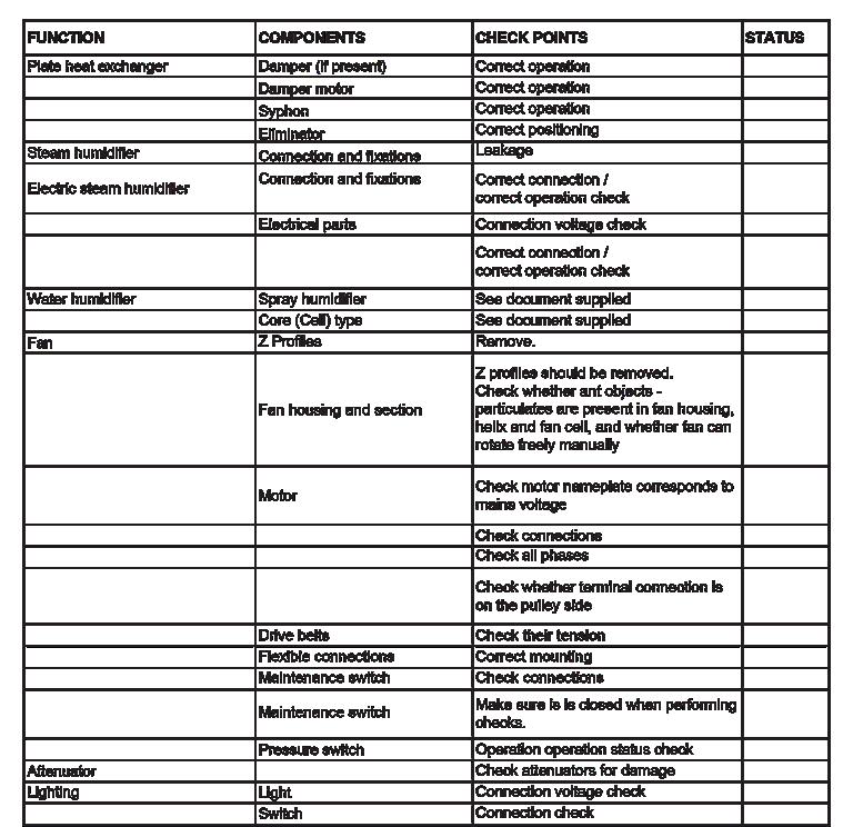
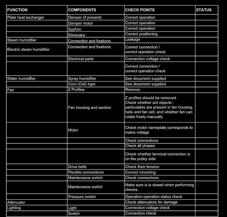
22 22 9. START-UP CHECK-LIST 9.1. Start-Up Inspection Items Check-list The table below shows a general overview of the planning required to facilitate the installation of the AHU. The following pages give a more detailed description of the individual components. CAUTION! Before starting up the AHU ensure that the components have the correct connection voltage and connect them in accordance with the regulations. The doors and access / guard covers must be closed and the AHU must be earthed Start-up Inspection Items
23 23


24 START-UP INSTRUCTIONS Casing The label indicating unit data, such as order number, unit type etc. is usually located on the access cover or door of the fan compartment. Caution: Before assembling the sections side-byside or stacked, insulation band supplied should be applied over section connection areas. Place the section as close as possible together before assembly. Assembly the sections towards each other by the aid of lifting bars and pulling ropes Casing panels Check the AHU panels for any damage. Any dirt or stains must be removed from the surface to prevent possible long-term damage. Building debris left on the roof must be removed. Dirt can be removed with water and a mild house-hold soap solution. Damage can be repaired by thoroughly cleaning the affected surface, then treat and paint as necessary. If applicable check the sealing joints and repair if required Doors and Access / Guard Covers Check the operation of door handles, locks and movement of the hinges Flexible Connections Check that all flexible connections are attached to the AHU and if necessary, tighten loose screws Earthing Ensure that the AHU has been earthed correctly and in accordance with local regulations. A label on the base frame indicates where the unit should be earthed Air Handling Unit Installation and Connections The floor in the room where the AHU is installed must be water-tight and water-drainable to prevent connection problems. Before the units are placed against or on top of each other, the sealing tape supplied must be attached between the casing sections. Fig. 48. Roof installation, method 2 The sections are connected to each other with section connection strips and aluminium metal sheets supplied. Sections pulled together are connected with stud bolts over cell connection strips located opposing to each other. Than, remove section connection strips one by one and screw aluminium bars instead. (Warning: Never leave cell connection strips on the unit.) If the AHU is installed outdoors, the roof connecting plate provided must be installed on the roof and when required properly sealed Siphon It is advised to use siphon to have a constant water drain at all the outlets of the cooling coil, humidifier and other wet areas of the Air Handling Units. Siphon application is very important not to have air suction or leakage from these outlets and also draining the water without overflow which may move inside the unit. For the sizing of the siphon (internal height of the siphon), static pressure of the location must be considered. For the positive and negative pressures it is mandatory to use different siphons (See Fig. 49
![25 Fig. 49. Negative pressure siphon R= P + 50 10 P [Pa]: Negative pressures in the unit. Calculation should be done without using (-) sign.](/docs-images/84/90881038/images/25-0.jpg "R [mm]: Distance from lower point of the pipe to ground at condensation tray outlet. There is no inconvenience if R value is set higher than the value found by calculation. Fig. 51.")
 / 10 + 50 mm H2: 50 mm Install negative pressure siphon not supplied from the factory according to Fig.")
25 25 Fig. 49. Negative pressure siphon R= P P [Pa]: Negative pressures in the unit. Calculation should be done without using (-) sign. R [mm]: Distance from lower point of the pipe to ground at condensation tray outlet. There is no inconvenience if R value is set higher than the value found by calculation. Fig. 51. U-folded negative pressure siphon H1 = (max positive pressure at cooling coil, Pa) / mm H2 1/2 x H1 Fig. 50. Positive pressure siphon H1 (max positive pressure at cooling coil, Pa) / mm H2: 50 mm Install negative pressure siphon not supplied from the factory according to Fig. 51. Positive pressure siphon should be filled with water before starting up the unit. Negative pressure siphon may only be applicable for negative drain. Negative pressure siphon can be set up as in Figure 49. Fig. 52. Negative pressure siphon installation In Figure 52, parts and assembly order of siphon are given. Only negative pressure siphon is delivered from the factory. A positive pressure siphon should be made using a U-bended pipe as shown in Fig. 50. The ball inside the negative pressure siphon provides drained water fill the siphon by preventing air suction. This ball also blocks suction discharges that may be produced during pressure shocks. Water drain direction marked with an arrow on the negative pressure siphon. Application types according to the pressure and siphon types are shown in Fig. 53.
26 26 For servo-motor controlled dampers, following to frost thermostat warning or after a power failure, check the operation after power is restored. Some dampers should be open while some other are closed. Fig. 54. Manual start-up Fig. 53. Multi-siphon installation Siphon outlets should not be raised over drain length or at the end of the line. If it is necessary due to an obstacle on the ground, H2 in siphon calculation should be considered, see Fig. 53. For 62 mm. base frames that requires siphon application, a base frame shown in Figure 50 is necessary under the air handling unit. The constructed base frame should be levelled and balanced. For AHU with NPU profile concrete base frame requirement and height must be checked and AHU installation area must be prepared according to the explanations above Dampers - If not installed in the factory, check whether damper motor has been installed in accordance with the instructions of the supplier. Check whether correct angle is set. Check whether dampers close correctly. Check whether damper is opening at correct angle. Fig. 55. Strat-up with damper motor
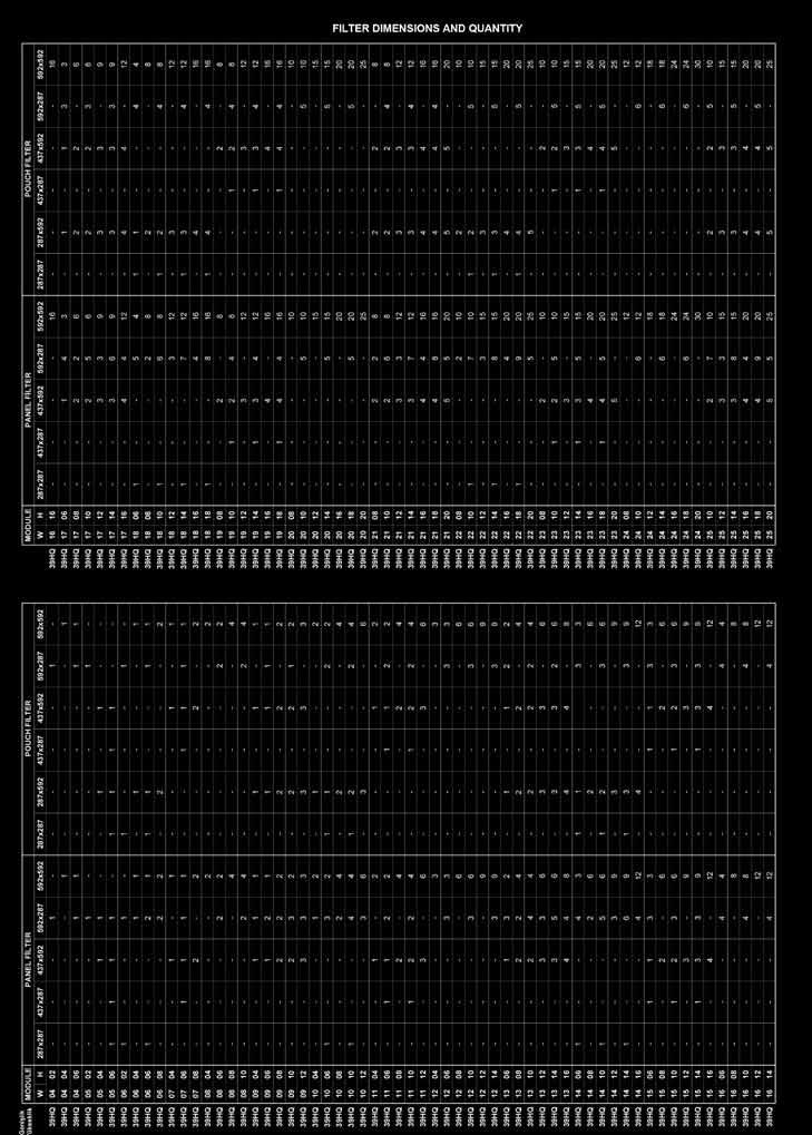
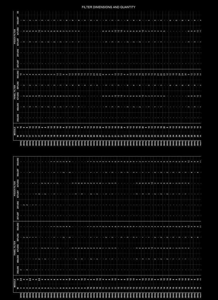
27 Air Filters Check if the correct filters have been installed. Check if filters are installed correctly. HEPA filters are supplied separately to prevent fouling during transport and start-up. Insert HEPA filters only after cleaning the unit. Set dirty filter pressure switch or filter indicators, if available. Close the door of filter cell. For further details about filter installation, see Appendix-2. For number of filters used or to be replaced, see Appendix Heaters General - Check the connections in accordance with the dimensional drawing. - Check the connections for leakage and sealing. - Make sure heater can supply enough heat to prevent frost formation once fan is started. Caution: For coils which water is used as heating or cooling medium (refrigerant), coils must be drained completely for preventing any possible damages on the coils when the temperature drops below 0 C. - The following warnings are attached to the panel: electric voltage and hot surface Steam Coil Steam coil surface temperature exceeds 100 C. Steam supply should be checked by authorized personnel. - Steam coil may only be switched on if specified minimum air flow is provided. - Make sure no foreign objects are left in steam coil section. - Steam coil should be closed at least 5 minutes before air handling unit is turned off. - The following warning is attached to the panel: hot surface Electric Heaters - Make sure heater has been connected in accordance with supplier instructions. Wiring diagram is located inside the electric connection box. - Check the current of electric heater. - Check whether safety devices shown in wiring diagram are installed. - Check whether heater is earthed in accordance with local instructions. - Electric heater may only be switched on if specified minimum air flow is provided. - Electric heater should be switched off at least 5 minutes before air handling unit is turned off. - Make sure no foreign objects are left in electric heater section Coolers - Check the connections in accordance with the dimensional drawing. - Check the connections for leaks. - Check drain siphon. If Alarko Carrier standard discharge siphon is used, check whether has been correctly installed. Check whether siphon cap and ball are installed correctly. - Comb the coil fins which were bended during transport - Check whether droplet eliminator pack after the cooler has been correctly installed. - Material to block water flow should not be placed inside the ceiling.
28 28 - After a period of time, check whether condensate is being drained and plastic siphon is operating. If required, clean the siphon Heat Recovery Wheel - Check that the wheel is rotating in the correct direction. This is indicated by an arrow on the casing. - Check whether rotary seals are fitted correctly. - Check whether belt tension is sufficient. - Check whether motor and control panel, if present, is correctly connected. - If present, check whether Check if the controller has been correctly connected and set in accordance with the instructions of the supplier. - Check whether rotor speed has been set correctly. - The following warning is attached to the panel: rotating parts - When making rotary inverter connection, use the cable supplied by the factory, see Fig. 56. Fig Plate Heat Exchanger For plate heat exchangers with bypass dampers: - Check whether damper motor has been installed in accordance with the instructions of the supplier. - Check whether the correct angle has been set. - Check whether dampers close correctly. - Check whether damper is opening at correct position. - Check operation after the power has been restored following a power cut. Some dampers should be open while others are closed. - Straighten the fins is they are bent during transport. - Check whether siphon has been correctly installed and check whether siphon cap and ball have been properly placed Steam Humidifier - Check fixing of steam pipe. - Check steam supply and condensate drain pipes. - For longer pipes install an extra drain pan in accordance with the instructions of the supplier. - Check whether the dirt trap has been installed. - Humidifier duct should left without pressure in accordance with the manufacturer s instructions. Refer to supplier instructions. - If humidifier cell has negative pressure, install a special siphon to humidifier cell. - Before starting up the steam humidifier, steam must be introduced slowly into the system to provide correct operation temperature of the humidifier. Once the condensate pipe reaches to operation temperature, start the actuator motor electrically or pneumatically and set the desired humidity level. Observe supplier instructions for all of these processes. - A few days after starting up the unit, clean the strainer of dirt trap and check the status of humidification duct. For casings with negative pressure, operation of the negative pressure system should be controlled with a check valve. - Steam humidifier should be closed at least 2 minutes before air handling unit is turned off. - The following warning is attached to the panel: hot surface Electric Steam Humidifier
29 29 - Check general fixing status of steam generator. - Check steam supply and drain pipes. - If humidification sections have negative pressure, install a siphon at humidifier cell. - Steam humidifier device should be closed at least 2 minutes before air handling unit is turned off. - Check the voltage and measure the circuit current. - Connect the humidifier according to supplier recommendations. - The following warning is attached to the panel: hot surface. housing together with information on pulley the belt is connected on. remove after transport Fig. 57. Fan Z-fixing Water spray humidifier Check supplier instructions Fan - Remove Z-profiles. Location of Z-profiles are shown on the label attached to the door. (Fig. 57) - For hygienic air handling units, when starting-up the fans, reinstall the screws removed from Z-profiles after Z-profiles are dismantled. - For fan motor couplings using Al profile, remove the square nut after Z-profile is dismantled. - Check whether terminal connection is on the pulley side. If required, turn terminal connection before connecting the wires. Check whether fan can move freely without touching the frame, flexible connection or wiring. Check mains voltage of electric motor. Check and/or connect the motor in accordance to local regulations and supplier instructions. Check the rotation direction of the fan. The direction is indicated on housing by an arrow. Measure current draw for all phases of electric motor. Current draw for all phases should be nearly the same and corresponding to data on unit nameplate. Set motor protection mechanism to its nominal value. Type of the belt used, belt tension and number of belts and their dimensions are indicated on the label attached to fan Caution: Air flow can lead moving of stationary parts (even if fan is switched off). Check whether flexible connections are correctly installed. To have control over belt ruptures, check pressure switch, if available and adjust to correct pressure. Check the operation main switch. Warning: While working on the fan make sure power is off. Warning regarding rotating parts, electric voltage and open doors are attached to the door. Label for removing Z-profiles is attached to floor of fan section Sound attenuator - Check attenuators for damage Lighting - Check connection voltage. - Check whether switch is operating. Switch should be installed in accordance to local regulations.


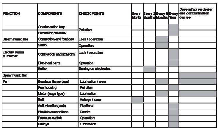
30 MAINTENANCE CHECK-LIST Inspection Items Check-list and Maintenance Intervals The table below shows a general overview of the planning required for inspection and maintenances of the AHU. On the following pages there are more detailed descriptions for individual components. CAUTION! Remember to de-energise all components and make sure fan has stopped rotating before opening the doors and access / guard covers to perform inspections and maintenance.

31 31
32 MAINTENANCE AND OP- ERATING INSTRUCTIONS General The smooth inside and outside finish of the panels makes maintenance very simple. For dry sections, check inside and outside of AHU casing thoroughly once a year. For wet sections (cooler and humidifiers), please see relevant chapters Casing panels Inside Installation (Indoors) a) Inspection of panel and all dry sections from inside. Remove impurities by water and mild soap solution. If finish paint is damaged, remove the rust formation and touch up with good quality anti-corrosive primer and paint. Outdoor air intake sections can show signs of corrosion as they contain wet parts and are affected by mist, rain and air pollutants. b) Inspection of coating from outside If paint is damaged, remove rust formation and touch up with good quality anti-corrosive primer and paint Outside Installation (Outdoors) Check the sealed joints of AHUs installed outside and if required seal again with a UV-resistant material that paint can be applied. Treat damage as for inside installation Doors and Access Covers Check locks and hinges of all doors and access covers Flexible Connections Check flexible connections for damage Earthing Make sure unit is earthed and installed in the properly Dampers All damper hinges are equipped with plastic bearing bushings. Therefore, no lubrication is required. Remove excess impurities by cleaning it with air jet. Clean aluminium parts with water and mild soap solution. Check screws and anchorages, re-tighten if required. Make sure damper blades run free of the casing and do not touch the flexible connection and duct connections Outdoor Air Intake Especially outdoor air intake gets contaminated by impurities taken in with the air. Maintenance intervals should be observed. Accumulated impurities can lead irreparable damages on the panels. Clean the outside air intake thoroughly and repair damages observes as described in Inside Installation (Indoors) chapter Air Filters The filters must be inspected once a month for excess pollution, pressure loss, damage and seating of the slide-in filters or built-in frames. With slide-in filters ensure that the filters have been correctly positioned and have been pushed well against each other from below. When replacing built-in filters you must ensure that the filter has been pushed well against the sealant and that the clips have been correctly installed. Filters must be replaced at required intervals. The timing of the replacement depends on the type of filter, quality and the degree of contamination of the air. The pressure drop across the contaminated filter can be measured with a pressure differential gauge. Maintenance instructions of special filters are available on request Heaters Water, Glycol and Steam Coils Check air intake once a year for contamination and clean with air jet, if required, against the direction of the air flow or clean air intake with a vacuum cleaner. Perform leakage check. Check the operation of frost protection thermostat and check the correct control sequence when thermostat trips. Glycol-charged heating and cooling exchangers must be checked annually for the actual percentage of glycol in the water. The following warning is located on the panel of steam heat exchanger: hot surface.

33 Electric Heaters Check for contamination once a year and if necessary clean with air jet. Check the connections in the control box. Check operation of thermostat. The following warning pictograms are attached to the panel: electric voltage and hot surface. If heat recovery wheel is controlled by a control panel, see supplier documents for further information about operation and maintenance details. The following warning pictogram is attached to the panel: rotating parts Coolers Check for contamination once a year and if necessary, clean with air jet against the direction of the air flow or clean with a vacuum cleaner. The eliminator assembly mounted after the cooler can be removed. Perform leakage check. Check fins of eliminator. Clean siphon and check its operation. Check the condensation pan for contamination and clean if necessary Heat Recovery Wheel Check rotor for contamination once a year and clean with air jet, if required. Check rotor speed and compare it with design data. Check the operation of the rotation monitor. Depending on roto-run material, rotary can absorb moisture. When stationary rotary will absorb moist on one side and thus become heavier. For rotary speed adjustment, see manufacturer operating manual. Rotor bearings are lubricated for complete life cycle and maintenance free. Drive motor is accessible via an inspection cover. V-belt is automatically tensioned by a spring-loaded rocking base on which motor is installed. New belts expand excessively the beginning. Therefore, when new belts are installed, check whether belt still has enough tension after two days. After this inspection, belt tension should be checked weekly during the first month and then once a month Plate Heat Exchanger Check plate heat exchanger for contamination once a year and if necessary, clean with air jet against the direction of air flow. If dampers are used, strictly follow the instructions in Dampers section. Check the condensation pan for contamination and clean if necessary Steam Humidifier Clean the filter in steam supply line once a year. If a filter is installed, also clean condensation drain valve and inside of condensation tray. Check control valve, condensation drain and distribution box twice a year. With steam distribution pipes in negative pressure systems (installed at air side) there may be excess water present, as the condensation may not drain from the steam distribution pipe. For some brands a special siphon with a check valve is supplied. Check the operation of this valve once a year. During periodical checks of the steam humidifier, casing sections after the humidifier should facilitate inspection and controlling of humidification level. When viewed in the direction of the air flow rate, there should not be any steam accumulated at the end of the steam humidification section. Electric humidifier capacity is strongly affected by contamination of steam boiler and electrodes. This is indicated by the LED. If required, replace steam boiler or the electrodes.
34 34 For further information regarding the operation and maintenance of steam humidifier, see supplier documents. The following warning is attached to the panel: hot surface Water spray humidifier For maintenance of water humidifier, see supplier documents Fan General - Warning: Air flow can lead moving of stationary parts (even if fan is switched off). - Warning: While working on the fan make sure power is off. - Type of the belt used, belt tension and number of belts and their dimensions are indicated on the label attached to fan housing and ventilator cell door together with information on pulley the belt is connected on. - Take care to insulation of terminal box when making motor cable connections. No humidity should enter into the box Bearings Bearings of smaller fans are closed type and do not require greasing. If larger fans that require greasing is used, grease them every six months. For higher temperatures and increased contamination greasing intervals should be adjusted as required. For the type of grease, observe fan manufacturer recommendations. For higher temperatures and a higher degree of humidity use a lubricant recommended by the supplier. Electric motors are equipped with roller bearings, depending on the motor size the bearings are lubricated for complete life cycle or are equipped with a grease nipple. The lubrication interval and type of lubricant are as above Power transmission After starting up the unit or after replacing the belts, belt tension has to be checked within one week for the first time and then after two weeks, and tension should be re-adjusted, if required. After that, check belt tension and inspect the condition of the belts every three months. CORRECT BELT TENSION depends on: - type of belt, - power to be transmitted, - belt speed. Belt tension is calculated for each transmission. If belt tension is too high this can result in premature wear at bearings and vibration. If it is too low this can result in belt slippage and belt wear. Sequence for installation of new belts: - Make sure that the pulleys are correctly aligned. If necessary, re-align. - Position all belts loosely on the pulleys, do not pull tensioned belts over pulleys. - Tension belt, check their tension. - Re-check alignment. If fan speed changes or if a motor with different power specifications and/or speed is installed, the manufacturer must be informed and no further work should be performed. Alarko Carrier will calculate the load to be carried by the fan and also bearing loads. Failure to perform this step may lead irreparable damages at fan. Alarko Carrier accepts no liability for any modifications done without approval. See chapter related with safety. - Warning pictograms are attached to the door indicating rotating parts, electric voltage and open doors.
35 Sound attenuator Under normal conditions, attenuators are maintenance free. Nevertheless it is recommended to check attenuators once a year for possible damage and loose fibre elements, in order to prevent further contamination of the system INSTRUCTIONS FOR HYGIENIC AHU s The information in this application pages is provided as a guideline for the cleaning and maintenance technicians. Please also refer to other parts of the mounting, installation operation and maintenance instructions. Storage Hygienic air handling units must be stored and installed indoors, never outdoors. Hygienic air handling units must be stored indoors, never outdoors. Dust-free, clean and dry conditions must be ensured during storage (on boards, if necessary, with the components being covered by water-resistant covering). Prior to installation, components shall be checked for coarse contamination and any such contamination found shall be removed. Do not unwrap the hygienic air handling units outdoors or in a dirty environment. General Only competent personnel under a qualified supervisor must carry out maintenance, repairs cleaning or modifications. The elements of the air handling unit are accessible upstream and downstream for cleaning purpose, but it is recomended to have them easily and safely removable; this shall be taken into account when making modifications on the fittings for pipes and ducts. Do not open any access panels or touch electrical components while voltage is applied unless it is necessary for measurements, tests or adjustments. Only a qualified electrician equipped with the proper tools, and wearing appropriate body protection against electrical hazards should carry out such work.before removing any panels from the enclosure, or dismantling any part of the unit, isolate from the main electrical power supply. Lock the isolator in the OFF position and remove the fuses. Attach a labelto the isolator switch carrying the warning WORKIN PROGESS DO NOT APPLY VOLTAGE. Do not switch on electrical power or attempt to start the unit if a warning label is attached. When handling, operating or carrying out maintenance on the unit, personnel must use safe engineering practices and observe all relevant local health and safety requirements and regulations. When air handling unit (AHU) products are installed over doorways or within the ceiling framework, most maintenance or repair work will be carried out at heights in excess of 2 metres. Suitable precautions should be taken to ensure that any access equipment used, ladders, towers, etc., are isolated from passing human traffic by the use of an appropriate barrier/ notice system. Any barriers used should be positioned at a suitable distance to remove risk of injury to passing personnel from dropped tools/components. All equipment used to gain access to work at height must be properly secured, and manned by sufficient support staff to meet National/Local safety regulations. Attention should be paid to the weight of units or individual components, particularly when being removed from the original installed location. Suitablelifting equipment, including slings, straps, hooks, etc, should be used as appropriate. Cleaning The elements of the air handling unit are accessible upstream and downstream for cleaning purpose but if the internal AHU functions have to be taken out for cleaning or maintenance purposes, where access is gained via removable panels, each enclosure panel can simply be removed from the outside to ensure complete and easy access to components, however, care should be taken to ensure the panel can be adequately supported when removed, particularly when working at height. Doors must be opened only by authorized persons. Prior to the commencement of any cleaning work, the HVAC system cleaning technicians shall per a visual inspection of the AHU to determine if thfoerme are any extra ordinary foreign objects that disturb AHU components and try to find the reasons. If damaged system components are found during the inspection they shall be documented and brought to the attention of the manufacturer. If replacement parts are needed, use only genuine Carrier spare parts. Replace missing or damaged fasteners and gaskets as required (sized to suit). Air-Volume Control Devices (dampers and any air-directional mechanical devices) of the AHU must have their position marked prior to cleaning, so that, upon completion, they can be restored to their marked po-
36 36 sition. Mechanical Cleaning AHU shall be cleaned using source removal mechanical cleaning methods designed to extract contaminants from within the HVAC system and safely remove contaminants from the facility. No cleaning method, or combination of methods, shall be used which could potentially damage components of the AHU or negatively alter the integrity of the system. Mechanical cleaning may employ; vacuum units mechanical and hand brushes pressurized air sources pressurized water sources steam other tools to dislodge attached particulate and debris and convey it to a collection device in a controlled manner. Cleaning the heating and cooling functions first, is adviced since you can use pressurised air or water for cleaning the coils. Do not use pressurized air for cleaning of foreign objects from other functions (other then heating and cooling coils) since the air may take the foreign objects to other parts of the air handling unit. Instead, use a vacuum cleaner to clean the unit of foreign objects. All methods used shall incorporate the use of vacuum collection devices that are operated continuously during cleaning. The vacuum collection device must be of sufficient power to render all areas being cleaned under negative pressure, such that containment of debris and the protection of the indoor environmentis assured. All vacuum devices exhausting air inside the building shall be equipped with HEPA filters (minimum efficiency), including hand-held vacuums and wetvacuums. All vacuum devices exhausting air outside the facility shall be equipped with Particulate Collection including adequate filtration to contain Debris removed from the HVAC system. Such devices shall exhaust in a manner that will not allow contaminants to reenter the facility. Release of debris outdoors must not violate any outdoor environmental standards, codes or regulations. Clean all internal surfaces and components. Remove visible surface contaminants and deposits from within the AHU. You can also wash the internal parts of the air handling unit (excluding filters, electrical components). Washing operation clean condensate collectors and drains. Assure that a suitable operative drainage system is in place prior to beginning wash down operations. A direct connection of the hygienic ahu water drains to the sewage system is not permitted. The water in the syphon should not freeze at any condition. A non-return mechanism should be installed to ensure that during all operating cycles as well as during stoppage no contaminants of any kind can be transferred from the condensate drain to the inlet air flow. Do not use any flammable liquid to clean any part of the unit. If chlorinated hydrocarbon non-flammable fluids are used for cleaning, safety precautions must be taken against any toxic vapours that may be released. External panels and grilles where fitted, should be cleaned with hot soapy water and a soft cloth from both inner and outer sides. As the paint finish is to be maintained, avoid the use of abrasives or strong detergents. You can do a preliminary wipe down using a 10:1 solution of deionized water and isopropyl alcohol. Do not use this solution on plastic. Door seals should be inspected and replaced if necessary. If, because of any reason, the sealing materials used in AHU have to be changed, they shall be closedpored; they shall not absorb any humidity or release any odours and, in particular, must not provide a nutrient substrate for microorganisms. Plastic materials used in air-handling areas where high values of relative humidity, or large quantities of water, are inherent in the intended use, must not provide a nutrient substrate for microorganisms (proof to be established in accordance with EN 846). Wiring: Check the unit for loose connections or frayed wiring. Clean and tighten all connections and repair or renew all frayed or damaged wires and cables. Take care not to damage the wiring when working on the unit. When refitting wires and cables make sure they will not be damaged in service by chafing or by contact with a hot surface. Always refer to the appropriate wiring diagram when refitting any components previously removed or renewed.
37 37 Don t spill cleaning m aterials over the motor and wiring. Dampers: Automatic close-down of dampers even, if the auxilary power is cut off, is required. Heating Coil: High operating temperatures are attained by electric heating elements or hot water coils during normal operation. Ensure all electric heating elements or hot water coils have cooled sufficiently to allow safe handling for cleaning purposes. Clean all coils and related com ponents, includingfins. Particular care should be taken to avoid damaging the heating elements/coil fins. Cleaning methods shall not cause any appreciable damage to, displacement of, inhibit heat transfer, or erosion of the coil surface or fins. Coils shall be thoroughly rinsed with clean water to remove any latent residues. Verification of Coil Clea ning: Cleaning must restore the coil pressure drop to within 10 percent of the pressure drop measured when the coil was first installed. If the original pressure drop is not known, the coil may be considered clean only if the coil is free of foreign matter and chemical residue, based on a thorough visual inspection. Cooling Coil: Clean all coils and related components, including evaporator fins including drain tubes and drip pans. Particular care should be taken to avoid damaging the cooling elements/coil fins. Cleaning methods shall not cause any appreciable damage to, displacement of, inhibit heat transfer, or erosion of the coil surface or fins. Coils shall be thoroughly rinsed with clean water to remove any latent residues. The water in the syphon should not freeze at any condition. A non-return mechanism should be installed to ensure that during all operating cycles as well as during stoppage no contaminants of any kind can be transferred from the condensate drain to the inlet air flow. Verification of Coil Cleaning : Cleaning must restore the coil pressure drop to within 10 percent of the pressure drop measured when the coil was first installed. If the original pressure drop is not known, the coil may be considered clean only if the coil is free of foreign matter and chemical residue, based on a thorough visual inspection. Filters: Check filters on a regular basis. Don t leave dirty filters in units without replacement. (Prolonged operation with restricted airflow through dirty filters can have a detrimental effect on the heating and cooling outputs, as well as putting unnecessary strain on the motor or motors resulting in reduced component life). Filters shall be changed only by the filters properties of which are in accordance with the filter stickers on the doors of the filter functions. Filters of the hygienic AHUs are throwaway type and are not to be cleaned by washing. Light dust deposits on the filter frames can be removed by the careful use of a soft brush and vacuum cleaner. Then filter frame can be washed or may be cleaned with hot soapy water and a soft cloth. Humidifiers: The upper limit value for non-pathogenic bacteria for humidifier water is cfu x ml 1. However, from a bacteria content of cfu x ml-1 (cfu:colony forming unit) onwards in the humidifier water, the plant should be checked and cleaned. National authorities can specify additional requirements to these default values. A person responsible for the maintenance and inspection of the humidification plants should be appointed All measures taken shall be recorded. Steam should not contain any substances representing a health hazard. For that reason, the steam humidifiers may only be operated with water of at least drinking water quality and that any flow-back to the drinking water must be excluded. During operation no condensate shall develop in the fresh air volume flow behind the air humidifier. This requirement must also be met in the event of an AHU failure or when there is no or only insufficient supply air volume flow. Disinfectants can be used during cleaning after all the accumulated dirt has been removed, however, disinfectants shall not get into the room air through the humidification process. Steam humidification is recommended, however if evaporative humidifier is used, sufficient overflow shall be arranged. Ultraviolet treatment and regular flushing are recommended.
38 38 Fans: Fans and blowers shall be thoroughly cleaned. Areas to be cleaned include blowers, fan housings, plenums (except ceiling supply and return plenums), scrolls, blades, or vanes, shafts, baffles, dampers and drive assemblies. All visible surface contamination deposits shall be removed. Fans, motors, electrical components, and internal casing should be cleaned with the use of a soft brush, e.g. paintbrush, and vacuum cleaner. Brush out dirt and dust etc. from the motor, fan impeller, fan casing and shafts. Use a vacuum cleaner and brush to remove dust from the motor ventilation holes to ensure that motor cooling is maintained at maximum efficiency. Don t use cleaning materials over the motor and wiring. Belts should be checked for wear and tension andshould be adjusted or replaced if necessary. Air Diffusers: Air diffusers may be cleaned with hot soapy water and a soft cloth. Attenuators: If there is any evidence of damage, deterioration, delamination, friable material, mold or fungus growth, or moisture such that fibrous glass materials cannot be restored by cleaning or resurfacing with an acceptable insulation repair coating, they shall be identified for replacement. If you need to take one of the attenuators a. Pull out the striping on the panel-profile cross section part. b. Take the panel out. c. Take the screws on the profiles which are fixing the attenuators out d. Take the attenuators out Cleanliness Verification: Following cleaning, a visual inspection of interior surfaces, shall be performed to verify the surfaces are visibly clean and free from non-adhered substances and debris. Verification of cleanliness will be determined after mechanical cleaning and before the application of any treatment or introduction of any treatment-related substance to the AHU, including biocidal agents and coatings. Visual Inspection: The AHU shall be inspected visually to ensure that no visible contaminants are left. 1. If no contaminants are evident through visual inspection, AHU shall be considered clean; however, cleanliness of the AHU can be verified through gravimetric or wipe testing analysis etc. 2. If visible contaminants are evident through visual inspection, those portions of the AHU where contam nants are visible shall be re-cleaned and subjected to re-inspection for cleanliness. Biocidal Agents and Coatings 1. Biocides can only be used if, under no circumstances, they are detrimental to the health of the occupants in the areas served by the air handling unit. 2. Biocidal agents shall only be applied if active fungal growth is reasonably suspected, or where unacceptable levels of fungal contamination have been verified through testing. 3. Application of any biocidal agents used to control the growth of fungal or bacteriological contaminants shall be performed after the removal of surface deposits and debris. 4. Biocidal agents shall be applied in strict accordance with manufacturer s instructions. 5. Biocidal coating products for both porous and non-porous surfaces shall be water soluble solutions with supporting efficiency data and MSDS records. 6. Biocidal coatings shall be applied according to manufacturer s instructions. Coatings shall be sprayed directly onto interior surfaces, rather than fogged downstream onto surfaces. A continuous film must be achieved on the surface to be treated by the coating application. Application of any biocidal coatings shall be in strict accordance with manufacturer s minimum millage surface application rate standards for effectiveness. Upon cleaning completion, all components must be returned to those settings recorded just prior to cleaning operations. Air-Volume Control Devices (dampers and any airdirectional mechanical devices) of the AHU, upon completion, must be restored to their marked position prior to cleaning.
39 Disposal of Unit Switching the Unit Off: Turn off power supply of the unit. Wait until unit is discharged mechanically and electrically. Dismantling the Unit: Dismantling works should be done by competent persons. Use original lifting equipment and proper lifting points. Components should be classified according to their material types and recycled or disposed according to local regulations. Recyclable Materials: Galvanized Metal Plates, Stainless Steel, Copper, Aluminium, Plastic, Fibreglass, Rockwool Parts, Electrical components. Recyclable Fluids: Basic fluids, refrigerants, compressor oil. Recycling of fluids should be done according to local regulations. Disposal of Electrical and Electronic Equipment Electronic components should be dismantled by competent persons and recycled according to local regulations.

40 40 APPENDIX-1 CELL INFO AND CONNECTION ORDER
41 APPENDIX-2 FRONT WITHDRAWAL FILTER DETAIL 41

42 42 APPENDIX-2 FRONT WITHDRAWAL POUCH FILTER INSTALLATION
43 APPENDIX-2 SIDE WITHDRAWAL COMBINED FILTER INSTALLATION 43
44 44 APPENDIX-2 SIDE WITHDRAWAL FILTER INSTALLATION (F8-F9)
45 APPENDIX-2 SIDE WITHDRAWAL FILTER INSTALLATION (F7) 45
46 46 APPENDIX-3/1 Side Withdrawal Filter

47 APPENDIX-3/2 Front Withdrawal Filter 47
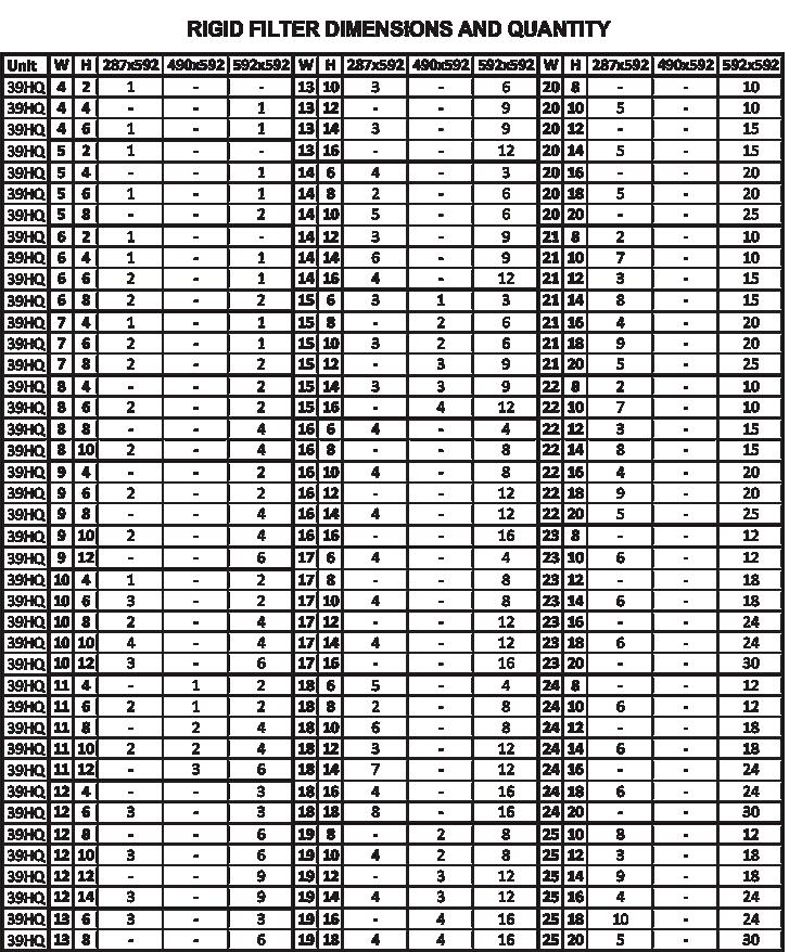
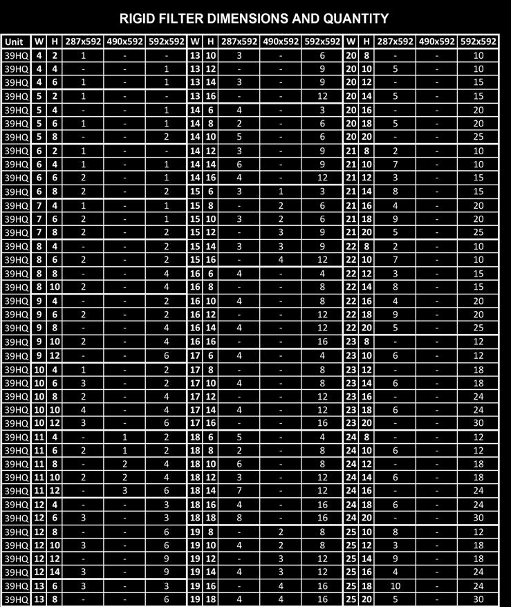
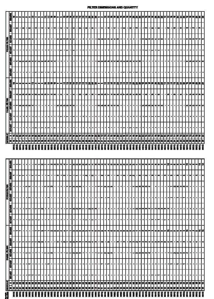
48 48 APPENDIX-3/3 Pleated Filter
49 49
50 50
51 51

52
Indholdsfortegnelse. Danvent Air Handling Units SERVICE MANUAL
 Indholdsfortegnelse Danvent Air Handling Units SERVICE MANUAL Service Servicing of the Air Handling Unit Your ventilation system is equipped with a Danvent Air Handling Unit (AHU) which will contribute
lindab we simplify construction Lindab Modular air handling units Service and maintenance manual
 Lindab Modular air handling units Service and maintenance manual Service and maintenance manual General... 3 2 Warnings and Tips... 3 3 Functional sections... 3 3.1 Fan section... 3 3.2 Heater section
Brown University Revised August 3, 2012 Facilities Design & Construction Standards SECTION AIR HANDLING UNITS
 SECTION 23 70 00 AIR HANDLING UNITS PART 1. GENERAL 1.1 Section includes air-handling units to 15,000 cfm and accessories. 1.2 Related Sections 1 : A. Division 01 - Brown University Standard for Narragansett
40LM Hz INSTALLATION, START-UP AND SERVICE INSTRUCTIONS CHILLED WATER FAN COIL UNIT
 Carrier International Sdn. Bhd. Malaysia INSTALLATION, START-UP AND SERVICE INSTRUCTIONS CHILLED WATER FAN COIL UNIT 40LM 120-200 50Hz CONTENTS: Physical Data & Dimension 1-3 Safety Considerations 4 Rigging
CS 2. Central Station Air Handlers Double Wall & Single Wall Installation, Operation & Maintenance Manual. Form No. 6120A
 CS 2 Central Station Air Handlers Double Wall & Single Wall Installation, Operation & Maintenance Manual Form No. 6120A TABLE OF CONTENTS Page Inspection... 2 Shipment of Units... 2 Handling... 2 Installation...
INSTALLATION, OPERATION, AND MAINTENANCE MANUAL
 INSTALLATION, OPERATION, AND MAINTENANCE MANUAL TUBE AXIAL FANS BTA, WTA, HTA, DDA The purpose of this manual is to aid in the proper installation and operation of the fans. These instructions are intended
EQGA AND EQGB HYGIENIC VERSION, CODE SUFFIX I = 3 AND 4
 EQGA AND EQGB HYGIENIC VERSION, CODE SUFFIX I = 3 AND 4 ASSEMBLY AND MAINTENANCE INSTRUCTIONS Contents Page Hygienic version..... 2 Delivery...... 2 Safety precautions...... 2 Mounting on the floor......
Instructions for the BASIC Air Handling System, Sizes General 1.1 Description of the System
 Instructions for the BASIC Air Handling System, Sizes 004 055 1. General 1.1 Description of the System The BASIC System is a complete modular air handling unit. The unit consists of blocks, i.e. a number
XB-EFA-8L-BK & XB-EFA-8R-BK
 Supply & Extract Ventilation Unit with Heat Recovery The EMC Directive 2014/30/EU The Low Voltage Directive 2014/35/EU The information contained in this document provides details of installation, operation
AIR HANDLERS. Central Station (CS3) Roof Mounted (RT) (Modular AL Frame AHU)
 Roof Mounted (RT) (Modular AL Frame AHU)") AIR HANDLERS Central Station (CS3) (Modular AL Frame AHU) Roof Mounted (RT) CONTENTS 1. CS3 Modular Aluminium Frame AHU : Unit Types 2. Casing Structure 3. Blowers and Drives 4. Coils 5. Options and Accessory
AIR HANDLERS Central Station (CS3) (Modular AL Frame AHU) Roof Mounted (RT) CONTENTS 1. CS3 Modular Aluminium Frame AHU : Unit Types 2. Casing Structure 3. Blowers and Drives 4. Coils 5. Options and Accessory
Preventative Maintenance Tables
 Preventative Maintenance Tables Table of Contents I. Table : Gas Fired Domestic Hot Water Heater II. III. IV. Table : Circulating Pump Table : Convectors Table 4: Grille and Diffusors V. Table 5: Unit
lindab we simplify construction Lindab Modular air handling units Transport and assembly manual
 lindab we simplify construction Lindab Modular air handling units Transport and assembly manual Transport and assembly manual 1 General... 3 2 Warnings & Tips... 3 3 Transportation... 3 3.1 Truck loading
GENERAL INSTRUCTION SAFETY DIRECTIVES INSTALLATION INSTRUCTION SAFETY DIRECTIVES GENERAL INSTRUCTION
 GENERAL INSTRUCTION SAFETY DIRECTIVES INSTALLATION INSTRUCTION SAFETY DIRECTIVES Using the air handling unit... Free space for service and repair work... GENERAL INSTRUCTION Checking prior to commissioning...3
MNEFDD54 & MNBCDD54 GALVANIZED WALL FANS Installation, Operation, and Maintenance Instructions
 FARM PRODUCTS DIVISION MEMBER OF AMCA AMERICAN COOLAIR CORPORATION P.O. BOX 2300 JACKSONVILLE, FLORIDA 32203 PHONE (904) 389-3646 FAX (904) 387-3449 E-MAIL - fans@coolair.com MNEFDD54 & MNBCDD54 GALVANIZED
INSTALLATION & MAINTENANCE
 INSTALLATION AND MAINTENANCE INSTRUCTIONS 1 INSTALLATION & MAINTENANCE FIBRE-REINFORCED PLASTIC AIR HANDLING UNITS fibre-reinforced plastic AHU 2 INSTALLATION AND MAINTENANCE INSTRUCTIONS Table of contents
SECTION AIR HANDLING UNIT
 SECTION 15800 - AIR HANDLING UNIT PART 1 - GENERAL 1.01 RELATED DOCUMENTS A. Basic Requirements: Provisions of Section 15010, BASIC MECHANICAL REQUIREMENTS, and Section 15030, ELECTRICAL REQUIREMENTS FOR
Installation, Operation, and Maintenance Information
 Installation, Operation, and Maintenance Information Air Cooled Condensers 8-2016 Rev 0 Table of Contents General Safety Information 2 Inspection 2 Installation 2 6 Rigging and Assembly 2 Unit Location
Series 1140 and 1141 Temperature Regulators
 Hoffman Specialty Installation & Maintenance Instructions HS-504(E) Series 1140 and 1141 Temperature Regulators! CAUTION FOLLOW ALL INSTALLATION AND OPERATING INSTRUCTIONS. TURN OFF WATER OR STEAM BEFORE
ISOLATED DIRECT DRIVE PLENUM FAN (IDDP)
") Our Expertise, Your Air-Moving Solution ISOLATED DIRECT DRIVE PLENUM FAN (IDDP) PART# 0601710001_rev_A INSTALLATION, OPERATION & MAINTENANCE MANUAL Please read and save these instructions for future reference.
Our Expertise, Your Air-Moving Solution ISOLATED DIRECT DRIVE PLENUM FAN (IDDP) PART# 0601710001_rev_A INSTALLATION, OPERATION & MAINTENANCE MANUAL Please read and save these instructions for future reference.
Enviro KES INSTALLATON MANUAL
 Enviro KES INSTALLATON MANUAL Spring Air Systems Inc., Oakville, Ontario Phone (905) 338-2999, Fax (905) 338-0179, info@springairsystems.com www.springairsystems.com KES Installation Manual. This publication
Installation of Glass Lined Equipment
 Installation of Glass Lined Equipment Information given herein is for guidance only and may not be complete. It is important that only trained and competent personnel are permitted to handle glass lined
Panel Fan Series Operators Manual (Galvanized and Polymer)
") Panel Fan Series Operators Manual (Galvanized and Polymer) Galvanized Panel Fan with Three Wing Blade IMPORTANT: READ AND SAVE THESE INSTRUCTIONS Read all instructions carefully before attempting to assemble,
Panel Fan Series Operators Manual (Galvanized and Polymer) Galvanized Panel Fan with Three Wing Blade IMPORTANT: READ AND SAVE THESE INSTRUCTIONS Read all instructions carefully before attempting to assemble,
Climaster ZerAx. Eco-designkrav. Climaster ZerAx type ZCN-M guide GB
 Climaster ZerAx Climaster ZerAx type ZCN-M guide 924784-0 GB Eco-designkrav Important This document is made available as it is. Novenco reserves the right to make changes without prior notice due to further
Panel Fan Series Operators Manual (Galvanized and Polymer)
") Panel Fan Series Operators Manual (Galvanized and Polymer) 52" Belt Drive, Galvanized Panel Fan with Three Wing Blade IMPORTANT: READ AND SAVE THESE INSTRUCTIONS Read all instructions carefully before
Panel Fan Series Operators Manual (Galvanized and Polymer) 52" Belt Drive, Galvanized Panel Fan with Three Wing Blade IMPORTANT: READ AND SAVE THESE INSTRUCTIONS Read all instructions carefully before
Assessment Schedule - TS8
 The Assessor shall determine the business s commitment and support to good and safe working practices; also that it has a positive culture in all aspects of its work. In particular, the assessor shall
Air handling units KLASIK. Unique solutions available Flexible performance & economy Reliable, stable & efficient Tight casing & perfect insulation
 Air handling units KLASIK Unique solutions available Flexible performance & economy Reliable, stable & efficient Tight casing & perfect insulation KLASIK air handling units Customer oriented and unique
User Manual Box Exhaust Fan Series (Belt Drive)
") User Manual Box Exhaust Fan Series (Belt Drive) 36" Box Exhaust Fan with Three Wing Blade Box with Aluminum Shutter 54" Box with Cone 800-779-3267 sales@schaeferfan.com www.schaeferfan.com 2013 Schaefer
User Manual Box Exhaust Fan Series (Belt Drive) 36" Box Exhaust Fan with Three Wing Blade Box with Aluminum Shutter 54" Box with Cone 800-779-3267 sales@schaeferfan.com www.schaeferfan.com 2013 Schaefer
CELDEK Evaporative Cooler Module Installation, Operation, and Maintenance Manual. CELDEK Evaporative Cooler
 CELDEK Evaporative Cooler Module Installation, Operation, and Maintenance Manual CELDEK Evaporative Cooler RECEIVING AND INSPECTION Upon receiving unit, check for any interior and exterior damage, and
Installation, Operating & Maintenance Instructions. Air Handler Models: AH & AV
 Installation, Operating & Maintenance Instructions Air Handler Models: AH & AV Table of Contents Table of Contents... 2 Product Safety... 2 Important Information About Safety Instructions... 2 Receiving...
Service Step by Step Trouble-Shooting Check-List
 WARNING: Only Data Aire trained technician or experience technicians should be working on Data Aire Equipment. Protect yourself at all times and work safe. Date: Dates at the job site: From: to Job#: Serial#:
MIST MAX MODEL MM800. Important: Installation and Operation Manual
 MIST MAX MODEL MM800 Installation and Operation Manual TM Important: This manual contains specific cautionary statements relative to worker safety. Read this manual thoroughly and follow as directed. It
PANEL FAN SERIES OPERATORS MANUAL (Galvanized and Polymer)
") PANEL FAN SERIES OPERATORS MANUAL (Galvanized and Polymer) Galvanized Panel Fan IMPORTANT: READ AND SAVE THESE INSTRUCTIONS Read all instructions carefully before attempting to assemble, install, operate
PANEL FAN SERIES OPERATORS MANUAL (Galvanized and Polymer) Galvanized Panel Fan IMPORTANT: READ AND SAVE THESE INSTRUCTIONS Read all instructions carefully before attempting to assemble, install, operate
If a peak space temperature to about 28ºC is acceptable to the occupants then a naturally ventilated solution is a viable option.
 Air handling units Aesthetic Not to add significantly to the existing ambient noise levels. Functional requirements If a peak space temperature to about 28ºC is acceptable to the occupants then a naturally
English CNA-CNB. Centrifugal fans Installation and maintenance
 916505-0 English CNA-CNB Centrifugal fans Installation and maintenance 916505-0 GB Centrifugal fans types CNA, CNB, CNA-M and CNB-M installation and maintenance 1. Application 2. Handling 2.1 Marking 2.2
Standard and CELDEK Evaporative Cooler Modules Installation, Operation, and Maintenance Manual
 Standard and CELDEK Evaporative Cooler Modules Installation, Operation, and Maintenance Manual Standard Evaporative Cooler CELDEK Evaporative Cooler RECEIVING AND INSPECTION Upon receiving unit, check
Standard and CELDEK Evaporative Cooler Modules Installation, Operation, and Maintenance Manual
 Standard and CELDEK Evaporative Cooler Modules Installation, Operation, and Maintenance Manual Standard Evaporative Cooler CELDEK Evaporative Cooler RECEIVING AND INSPECTION Upon receiving unit, check
Installer manual GreenMaster-HP
 Installer manual GreenMaster-HP Transport and installation Ventilation unit IHB EN 1747-2 8017172 2 GreenMaster-HP Transport and installation Introduction Here you can read about how best to handle the
OK, OKA, OKAF; ELD; ELDM; ELH; OKC; SC; SCA; SCAF; OK-LN; OKA-LN; OKAF-LN.
 INSTALLATION, OPERATION & SERVICE MANUAL FOR COOLER TYPES OK, OKA, OKAF; ELD; ELDM; ELH; OKC; SC; SCA; SCAF; OK-LN; OKA-LN; OKAF-LN. 1. Introduction This manual is a guide for the installation, maintenance
DUCT COOLERS KWK KFK OPERATION MANUAL. KWK_KFK_v2(4)_EN.indd :35:29
_EN.indd :35:29") DUCT COOLERS KWK KFK EN OPERATION MANUAL KWK_KFK_v2(4)_EN.indd 1 13.06.2016 13:35:29 CONTENTS 3 Introduction 3 General 3 Safety rules 3 Transportation and storage regulations 3 Manufacturer s warranty
DUCT COOLERS KWK KFK EN OPERATION MANUAL KWK_KFK_v2(4)_EN.indd 1 13.06.2016 13:35:29 CONTENTS 3 Introduction 3 General 3 Safety rules 3 Transportation and storage regulations 3 Manufacturer s warranty
AHU INSTALLATION & OPERATION MANUAL
 AHU INSTALLATION & OPERATION MANUAL VERSION 2 AIR HANDLING UNIT MODELS: AHU 500, AHU 900, AHU 1200, AHU 1700, AHU 2000, AHU 2500, AHU3500, AHU 4500, AHU 5000, AHU 6000, AHU 7000, AHU 8000, AHU 10000, AHU
Armstrong J Series Float, Thermostatic Steam Traps, Condensate Controllers & Liquid Drainers Installation and Maintenance Manual
 Armstrong J Series, Thermostatic Steam Traps, Condensate Controllers & Liquid Drainers Installation and Maintenance Manual This bulletin should be used by experienced personnel as a guide to the installation
PERFECT FIT IN-DASH HEAT/ COOL/ DEFROST FORD PICKUP
 specializing in AIR CONDITIONING, PARTS AND SYSTEMS for your classic vehicle PERFECT FIT IN-DASH HEAT/ COOL/ DEFROST 1960-66 FORD PICKUP CONTROL & OPERATING INSTRUCTIONS The controls on your new Perfect
Decentralised ventilation units
 Notes on installation Decentralised ventilation units FSL / SCHOOLAIR GB/en TROX GmbH Heinrich-Trox-Platz 47504 Neukirchen-Vluyn Germany Phone: +49 (0) 2845 2020 Fax: +49 (0) 2845 202265 E-mail: trox@trox.de
MJC Cartridge Filter Unit Operation & Maintenance
 1 of 19 Hodge Clemco Ltd MJC Cartridge Filter Unit Operation & Maintenance Owner s Manual Date of Issue: 19.07.04 TSSM536.1a Hodge Clemco Ltd Orgreave Drive Sheffield S13 9NR Tel: 0114 254 8811 Fax: 0114
57" Fiberglass Exhaust Fan with Cone
 OPERATORS MANUAL Fiberglass Exhaust Fan IMPORTANT: READ AND SAVE THESE INSTRUCTIONS Read all instructions carefully before attempting to assemble, install, operate or service the product described. Failure
Part 2: Installation Instructions cl
 Contents Page: Part 2: Installation Instructions cl. 381-382 1. Delivery scope............................... 3 2. General and Transportation safety precautions........... 3 3. Stand installation 3.1 Installing
This label warns for risk of electrical shock when failing to observe.
 MANUAL horizontal centrifugal pumps MB series ic drive SB series mechanical seal 1. Introduction 2. Safety precautions 3. Receipt 4. Installation / Operation and Maintenance 4.1 Installation 4.2 Operation
OWNERS INSTRUCTION MANUAL
 OWNERS INSTRUCTION MANUAL 132CM/52 Classic INSTALLATION OPERATION MAINTENANCE CAUTION READ INSTRUCTIONS CAREFULLY FOR SAFE INSTALLATION AND FAN OPERATION. IF UNSURE CONSULT A QUALIFIED ELECTRICIAN SUITABLE
Installation Operation Maintenance. Ductable water unit FWD FWD-SVX01D-E4
 Installation Operation Maintenance Ductable water unit FWD 08-12 - 20-30 - 45 General Information Foreword These installation, operation and maintenance instructions are given as a guide to good practice
Air Handler Unit. Installation & Operations Manual. Table of Contents. Bulletin No. H-IM-AH August 2002 Part Number 4346B001
 Bulletin No. HIMAH August 2002 Part Number 4346B001 (Replaces HIM71A, August 2002) Installation & Operations Manual Air Handler Unit Table of Contents Inspection...2 Shipment of Units Handling Suspended
Operating Guide. Termix Compact 28 VX-FI / HWP / HWS. 1.0 Table of Contents. 1.0 Table of Contents
 1.0 Table of Contents 1.0 Table of Contents... 1........................................................................ 2 2.0 Functional description... 3 3.0 Safety notes... 4 3.1 Safety Notes general............................................
lindab we simplify construction Lindab Modular air handling units Connection, start-up and commissioning manual
 Lindab Modular air handling units Connection, start-up and commissioning manual Connection, start-up and commissioning manual 1 General... 3 2 Warnings and Tips... 3 3 Functional sections... 3 3.1 Fan
INVERTER SPLIT - TYPE
 INVERTER SPLIT - TYPE ISSUE No 2 DATE 04/09/08 P/No 2020323A2868 CONTENTS SAFETY PRECAUTIONS Warning 2 Operating temperature 2 BEFORE INSTALLATION Tools needed for installation 3 Items required for installing
G-10s. Instruction Manual. G-Series Cooler UPRIGHT COOLER. Part No.11IPA
 G-Series Cooler UPRIGHT COOLER Part No.11IPA-062800 Instruction Manual FOR YOUR FUTURE REFERENCE Thank you for using our product. This manual will guide you in getting the best use of your cooler. Remember
Inverted Bucket Steam Traps
 INSTALLATION AND MAINTENANCE INSTRUCTIONS IM-2-00-US December 201 Inverted Bucket Steam Traps Safety Information Safe operation of these products can only be guaranteed if they are properly installed,
Installation, Operation and Maintenance Instructions for Thermax Semi-Storage Calorifier
 OM001 Installation, Operation and Maintenance Instructions for Thermax Semi-Storage Calorifier These operating and maintenance instructions are for standard semi-storage calorifiers (vessels fitted with
Installation Instructions Part No , Part No Part No
 Torsion-Flex Motor mount for PSC motors and Rigid-Mount for ECM motors Replacement Kit Cancels: New Installation Instructions Part No. 327752-401, Part No. 327753-401 Part No. 327754-401 IIK-310A-45-11
ETA ACCU 90% HIGHEST EFFICIENCY AIR HANDLING UNIT
 90% EFFICIENCY HIGHEST EFFICIENCY AIR HANDLING UNIT Packaged energy recovery solutions for Green Buildings Integrated Accumulator, controls and DX Cooling System CLEAN AIR SINCE 1963 Euroclima is a company
Hodge Clemco Ltd. MJC Mini Cartridge Filters Owners Manual. TSOM 556 Date of issue 13/07/04. Hodge Clemco Ltd
 1 MJC Mini Cartridge Filters Owners Manual TSOM 556 Date of Issue: 13.07.04 Orgreave Drive, Sheffield South Yorkshire. S13 9NR Tel:0114 254 0600 Fax: 0114 2540250 Email:sales@hodgeclemco.co.uk www.hodgeclemco.co.uk
SAFETY AND INSTALLATION MANUAL MODEL 8100
 SAFETY AND INSTALLATION MANUAL ENERGY RECOVERY VENTILATORS MODEL 8100 Provides year-round fresh air Recovers 77% of the apparent heating or cooling energy from the exhausted air See Warnings Page 3 Table
1. Description INSTRUCTION FOR BLAST COOLER TYPE COOL 250. Material
 1. Description General The cooler is used for cooling of water, oil or other liquid by use of air. The liquid is passing in the tubes where it transfere the energy to the air via the fins on the outside
VertiCool Space Saver
 Single Package Vertical Unit (SPVU) Installation, Operation and Maintenance Manual Effective September 2016 2 to 15 Tons Water-Cooled and Chilled Water Air-Cooled w/remote Condenser Contents Important
G-7s. Instruction Manual. G-Series Cooler COUNTERTOP COOLER. Part No.11IPA
 G-Series Cooler COUNTERTOP COOLER Part No.11IPA-061000 Instruction Manual FOR YOUR FUTURE REFERENCE This easy-to-use manual will guide you in getting the best use of your cooler. Remember to record the
Centeral Station Air Handling Unit
 Centeral Station Air Handling Unit CA Series www.windind.com www.windind.com The product range includes double skinned Air Handling Units, double skinned Fan Coil Units, and custom designed packaged roof
HEATING AND VENTILATION
 SECTION 14-102.04 14-102.04/ 1 2007OC19 DESCRIPTION The heating, ventilation and air conditioning (HVAC) system is designed to optimize passenger comfort. The system regulates interior vehicle atmosphere,
1.1 This section applies to air handling units for HVAC Systems.
 AIR HANDLING UNITS GENERAL INFORMATION 1.1 This section applies to air handling units for HVAC Systems. DESIGN REQUIREMENTS 2.1 Design Criteria a. The decision to use modular central station air handling
User Manual GV25 GV35 GV702. Company information: Original instructions GV12066 (1)
") User Manual Original instructions GV25 GV35 GV702 Company information: www.vipercleaning.eu info-eu@vipercleaning.com GV12066 (1) 2012-04-10 USER MANUAL ENGLISH TABLE OF CONTENTS Introduction... 4 Manual
User Manual Original instructions GV25 GV35 GV702 Company information: www.vipercleaning.eu info-eu@vipercleaning.com GV12066 (1) 2012-04-10 USER MANUAL ENGLISH TABLE OF CONTENTS Introduction... 4 Manual
1. Description INSTRUCTION FOR AIR BLAST COOLER TYPE COOL 450
 1. Description General The cooler is used for cooling of water, oil or other liquid by use of air. The liquid is passing in the tubes where it transfere the energy to the air via the fins on the outside
Installation & Maintenance Data IM Contents
 Installation & Maintenance Data IM 254-4 Group: Fan Coil Part Number: 107133000 Date: June 1999 SeasonMaker HiLine Fan-coil Units Type KZZ Contents Inspection..................................... 2 Riser
RV Products Division INSTALLATION INSTRUCTIONS FOR SERIES PACKAGE AIR CONDITIONER
 RV Products Division INSTALLATION INSTRUCTIONS FOR 46413 SERIES PACKAGE AIR CONDITIONER 1. WARNINGS IMPORTANT NOTICE These instructions are for the use of qualified individuals specially trained and experienced
Air handling units KLASIK. Unique solutions available Flexible performance & economy Reliable, stable & efficient Tight casing & perfect insulation
 Air handling units KLASIK Unique solutions available Flexible performance & economy Reliable, stable & efficient Tight casing & perfect insulation KLASIK air handling units Customer oriented and unique
Instructions for operation and maintenance
 KOJA oy KOJAmarine KOJAcool oy Air handling unit Future Instructions for operation and maintenance www.koja.fi 2 Index 1. General...4 2. Commissioning and maintenance...5 Damper section FPTP... 6 Mixing
Installation, Operation, and Maintenance Manual
 READ AND SAVE THESE INSTRUCTIONS PART # 538 Model BCF Belt Drive Centrifugal Cabinet Fans Installation, Operation, and Maintenance Manual Please read and save these instructions for future reference. Read
INSTALLATION MANUAL. Split-type Air Conditioner (Cooling and Heating) Outdoor Unit UQB09JJWC UQB12JJWC. Indoor Unit AQB09JJWC AQB12JJWC
 Outdoor Unit UQB09JJWC UQB12JJWC. Indoor Unit AQB09JJWC AQB12JJWC") AQB09JJ6WC_IM_E_2585 2006.4.17 4:26 PM Page 17 INSTALLATION MANUAL Indoor Unit AQB09JJWC AQB12JJWC Outdoor Unit UQB09JJWC UQB12JJWC ENGLISH FRANÇAIS ESPAÑOL Split-type Air Conditioner (Cooling and Heating)
AQB09JJ6WC_IM_E_2585 2006.4.17 4:26 PM Page 17 INSTALLATION MANUAL Indoor Unit AQB09JJWC AQB12JJWC Outdoor Unit UQB09JJWC UQB12JJWC ENGLISH FRANÇAIS ESPAÑOL Split-type Air Conditioner (Cooling and Heating)
VERTICAL HIGH OUTPUT VHC-IOM INSTALLATION AND MAINTENANCE INSTRUCTIONS VHC INSTALLER MUST BE A TRAINED, EXPERIENCED SERVICE TECHNICIAN
 VHC INSTALLER MUST BE A TRAINED, EXPERIENCED SERVICE TECHNICIAN 1. PRESSURE CHECK When the valve package is factory installed, the unit is shipped with the coil and associated piping/valve package pressurized.
Installation Manual PS-225 & PS-275
 Installation Manual PS-225 & PS-275 Table of Contents Pre-Uncrating Checklist... 1 Verifying System Requirements... 2 Verifying System Direction... 2 Verifying the Electrical Requirements... 2 Removal
Ductless Split Air Conditioner
 Ductless Split Air Conditioner Installation Manual Indoor HSU09VHG(DB)-W HSU12VHG(DB)-W HSU18VHH(DB)-W HSU24VHG(DB)-W Outdoor HSU09VHG(DB)-G HSU12VHG(DB)-G HSU18VHH(DB)-G HSU24VHG(DB)-G Table of Contents
DOMEKT ReGO 400VE(W)-B Series Air Handling Units Installation and Maintenance Service Manual
-B Series Air Handling Units Installation and Maintenance Service Manual") DOMEKT ReGO 400VE(W)-B Series Air Handling Units EN Content Safety Requirements...3 Transportation...3 Brief Description of the Unit...5 Installation...6 Maintenance...11 Technical Information......13
DOMEKT ReGO 400VE(W)-B Series Air Handling Units EN Content Safety Requirements...3 Transportation...3 Brief Description of the Unit...5 Installation...6 Maintenance...11 Technical Information......13
HIGH EFFICIENCY POOL DEHUMIDIFIER AND CONDITIONER WITH HIGH HEAT RECOVERY RATES. Air treatment unit. Swimming pool waste air 28 C-65%
 Dry HIGH EFFICIENCY POOL DEHUMIDIFIER AND CONDITIONER WITH HIGH HEAT RECOVERY RATES Calculation of savings (for illustrative purposes) Operating scheme Note: power rates refer to 10,000 m 3 /h of air and
Jet Fan Types AUC/ARC/AUR/ARR/AUO/ARO Installation and Maintenance
 916503-0 GB Jet Fan Types AUC/ARC/AUR/ARR/AUO/ARO Installation and Maintenance 1. Main components 2. Application 3. Handling 3.1 Marking 3.2 Weight 3.3 Transport 4. Storage 1. Main components: Types ARC,
TECHNICAL MANUAL TRAY DRYER
 TECHNICAL MANUAL FOR TRAY DRYER MODEL TD321-3 TRAYDRYER MODEL: TD 321-3 Table of Contents Part 1 - Technical Information * Introduction * Catalogue Cut-sheet and Installation Drawing * Warranty Part 2
Installation, Operating & Maintenance Instructions. Horizontal Models: LH & HL
 Installation, Operating & Maintenance Instructions Horizontal Models: LH & HL Table of Contents Table of Contents... 2 Product Safety... 2 Important Information About Safety Instructions... 2 Receiving...
Installation, Operation and Maintenance LOK-FLANGE Multitube Heat Exchangers
 Bulletin 1200/4 (Revised 5/12) Installation, Operation and Maintenance LOK-FLANGE Multitube Heat Exchangers INNOVATORS IN HEAT TRANSFER I. INSTALLATION OF HEAT EXCHANGERS A. HEAT EXCHANGER SETTINGS 1)
50BY, BL. Ÿà Õ µ µ Èß ËÕߪ Õ» å Single-Package Cooling Units 50BY, BL 50BY, BL
 50BY, BL Ÿà Õ µ µ Èß ËÕߪ Õ» å Single-Package Cooling Units 50BY, BL 50BY, BL Contents Safety Considerations... 4 Danger... 4 Warning... 4 Installation... 5-6 Air Duct Connection... 6 Electrical Wiring...
SeasonMaker Hi-Line Fan-coil Units Model HSS S10 & S12
 Installation & Maintenance Data IM 168-5 SeasonMaker Hi-Line Fan-coil Units Model HSS S10 & S12 Group: Fan coil Part Number: # 107132900 Date: June 1999 Table of Contents Inspection............................................................................
Grain crusher Universal. Purpose: This machine is designed for the crushing of grain in agricultural operation.
 Grain crusher Universal. Purpose: This machine is designed for the crushing of grain in agricultural operation. Operating instructions and parts catalogue This grain crusher provides you with a machine
CxA to Answer this Section
 EXHIBIT 01 91 13-3, SAMPLE Construction checklist items are to be completed as part of initial checkout and subsequent startup, preparatory to Functional testing. This checklist does not take the place
51AKS I S O OWNER S MANUAL
 LLOYD'S REGISTER QUALITY ASSURANCE 51AKS I S O 9 00 1 OWNER S MANUAL This manual applies to the following models Stand-alone Split 51AKS 085--- 51AKS 010--- 51AKS 185--- 51AKS 013--- 51AKS 113--- 51AKS
Complete HVAC Capability. Central Station Air Handling Units. Publication No. WT-CSX-0616A
 Publication No. WT-CSX-0616A Central Station Air Handling Units Complete HVAC Capability Horizontal Draw-Thru to Size 65 Vertical Draw-Thru to Size 50 1000 to 60,000 CFM Forward Curved or Airfoil Wheels
SWP. (Models SWP08 through SWP20) IMPORTANT! Read before proceeding! OPERATION & MAINTENANCE MANUAL
 IMPORTANT! Read before proceeding! OPERATION & MAINTENANCE MANUAL") SWP (Models SWP08 through SWP20) OPERATION & MAINTENANCE MANUAL IMPORTANT! Read before proceeding! Read carefully before attempting to assemble, install, operate or maintain the product described. Protect
SWP (Models SWP08 through SWP20) OPERATION & MAINTENANCE MANUAL IMPORTANT! Read before proceeding! Read carefully before attempting to assemble, install, operate or maintain the product described. Protect
 EC Box Fan www.flaktwoods.com/oandm Safety, Installation, Operation and Maintenance Instructions CONTENTS Paragraphs Safety 1 Handling/Storage 2 Installation (Mechanical) 3 Fig. 1: Fig. 2: Tilt Mechanism
Installation and operating instructions. DK energy storage and DK energy buffer
 Installation and operating instructions DK energy storage and DK energy buffer Edition: 08-2015 1 Preliminary note With this DK energy storage / DK energy buffer you purchased a DK quality product. The
WALL MOUNT RANGE HOOD. This manual is made with 100 % recycled paper. Electronic version of this manual is available at:
 WALL MOUNT RANGE HOOD This manual is made with 100 % recycled paper. Electronic version of this manual is available at: www.cosmoappliances.com Thank You Thank you for your purchase. We know that you have
442 Chapter 16. Figure 16-5 Gas leak detection
 BRORANE BRORANEBRORANEBRORANEBRORANEBRORANEBRORANEBRORANE 442 Chapter 16 Tur n e r BRORANE FUEL EBRORANEBRORANEBRORANEBRORANEBRORANE Figure 16-5 Gas leak detection is easy. This sensitive halide detector
Niles Steel Tank Hot Water Generator Installation and Operation Manual
 Niles Steel Tank Hot Water Generator Installation and Operation Manual Contents: Contents 1 Hazard definitions 1 1. General Information.... 2 Availability... 3 Optional Control Packages... 5 2. Installation....
HEATING AND AIR CONDITIONING
 WJ HEATING AND AIR CONDITIONING 24-1 HEATING AND AIR CONDITIONING TABLE OF CONTENTS page SERVICE PROCEDURES REFRIGERANT OIL LEVEL...1 REFRIGERANT RECOVERY....1 REFRIGERANT SYSTEM CHARGE...1 REFRIGERANT
GCG-9. Instruction Manual. G-Series Cooler. Manual is for the following models: GCG-9-N13EB G-9-N13EB GCG-9-B13EB UPRIGHT COOLER
 G-Series Cooler UPRIGHT COOLER Manual is for the following models: -N13EB G-9-N13EB -B13EB Instruction Manual FOR YOUR FUTURE REFERENCE This easy-to-use manual will guide you in getting the best use of
COLMAC COIL. Installation, Operation, and Maintenance ENG Rev A. Air Cooled Fluid Coolers. Contents. When you want Quality, specify COLMAC!
 COIL Manufacturing Inc. When you want Quality, specify COLMAC! Installation, Operation, and Maintenance ENG00018621 Rev A Air Cooled Fluid Coolers Contents 1. SAFETY INSTRUCTIONS... 1 2. MODEL NOMECLATURE...
XC-18. NOTE: *Machine shown without Lift-Up Safety Guard. This guard is included with machine. Machine should not be operated without this guard.
 XC-18 NOTE: *Machine shown without Lift-Up Safety Guard. This guard is included with machine. Machine should not be operated without this guard. EXTREMA MACHINERY COMPANY, INC. PO BOX 1450, ALBANY, LOUISIANA
Table of Contents. Specifications... page 2. Installation... page 3. Customizing... page 4. Reversing door swing... page 5
 Introduction The Scotsman Compact Refrigerator is a unique product, capable of being built into a cabinet because of its front vented, forced-air cooling system. It s also designed to be a companion to