NEW. communication protocol. Control board with Modbus. Air Conditioning SkyStar SkyStar ECM Cassette Fan Coil Units
|
|
|
- Caroline Lang
- 6 years ago
- Views:
Transcription


1 NEW Control board with Modbus communication protocol Air Conditioning ECM Cassette Fan Coil Units Quality management systems ISO 9001 Cert. n 0545/5


2 MD-600 Version CONTENTS Introduction Page 3 Main components Page 4 EUROVENT Certifications Page 5 Emissions Page 6 side pressure drop Page 9 Working conditions Page 9 Dimensions and weights Page 10 Air throw Page 12 Fresh air supply e Air distribution Page 13 Accessories Page 14 CRYSTALL electrostatic filter Page 16 Wall electronic controls Page 20 FreeSabiana wireless control system Page 24 Controls for S MB versions Page 26 Electric heater S E Page 27 ECM Introduction Page 28 Main components Page 29 EUROVENT Certifications Page 30 Emissions Page 31 side pressure drop Page 33 Working conditions Page 33 Dimensions and weights Page 34 Air throw Page 36 Accessories Page 37 S ECM configuration Page 39 Wall electronic control Page 40 Controls for S ECM MB versions Page 42 / ECM MB power electronic board Page 43 T-MB wall mounted control Page 44 RT03 infra-red remote control Page 45 PSM-DI multifunction control Page 47 Sabianet management system Page 48 PSM-DI and Sabianet accessories Page 48 MCT Introduction Page 51 Dimensions and weights Page 52 Assembly diagram Page 53 Components of the casing e Valve kit Page 54 Sabiana take part to the Eurovent program of fan coil performance certification. The official figures are published in the web site and in the web site The tested performances are: Cooling total emission at the following conditions: - temperature +7 C E.W.T. +12 C L.W.T. - Entering air temperature +27 C dry bulb +19 C wet bulb Heating emission (2 pipe units) at the following conditions: - Entering water temperature +50 C - Entering air temperature +20 C - rate as for the cooling conditions Cooling sensible emission at the following conditions: - temperature +7 C E.W.T. +12 C L.W.T. - Entering air temperature +27 C dry bulb +19 C wet bulb Heating emission (4 pipe units) at the following conditions: - temperature +70 C E.W.T. +60 C L.W.T. - Entering air temperature +20 C Fan absorption pressure drop Sound power

3 Introduction Innovating and beautiful design, seven different sizes, high control flexibility, easy maintenance: the new chilled water cassette is the result of an extended technical and design development aimed at achieving the highest level in terms of performance, silent operation and control possibilities. The air diffuser has an highly attractive aesthetical appearance, very innovative, and is also able to offer the best air distribution performance thanks to long computer studies and laboratory tests. The standard colour is RAL 9003, other colours available on request. The 4 smaller sizes are designed to fit into 600x600 mm false ceiling standard modules. The 3 bigger sizes have a dimension of 800x800 mm which allows the best outcome in terms of quietness and of price/performance ratio for these high capacity models. Every unit can be supplied with 1 battery (2 pipe system) and a possible electric heater or with 2 batteries (4 pipe system). Each model can have fresh air intake and a remote air diffuser can be connected to the unit. The condensate pump is integral with the unit, is very quiet and has a maximum head of 650 mm. In addition to the temperature and speed standard controls, automatic speed selection is also available. More than one unit can be connected to a single control, and the unit control panel can be installed in a position that facilitates the maintenance operation. Every unit can also be operated by the means of an infra-red remote control. The cassettes can also be connected to the most common automatic building management systems. It is also possible to use a completely wireless electronic control system based on radio communication called Free Sabiana, with great advantages in terms of installation flexibility and maximum precision in measuring room temperature. Finally, each unit can be equipped with a low energy consumption electric motor that is controlled by an inverter card that makes possible continuous air variations. 3
4 Main components INTAE GRID AND DISTRIBUTION OF THE AIR Intake grids, frame and adjustable air distribution louvers on each side, made from ABS. HTA version : white ABS, RAL 9003 HTB version : with intake grid, frame and louvers, choice of one colour only HTC version : with intake grid and louvers, choice of one colour, plus white ABS frame RAL 9003 HTD version : with louvers, choice of one colour, while the grid and frame are made from ABS, RAL 9003 MD-600 version : metal diffuser painted in RAL 9003 white colour with 600x600 dimension to perfectly fit into the false ceiling standard modules without overlapping parts (800x800 model is not available). CASING Is made from galvanized steel with inside thermal insulation with polyolefin (PO) foam (class M1) and outside anti-condensate lining. CONTROL PANEL Made of an external box with the control electronic board with an easily accessible terminal board. FAN ASSEMBLY The fan assembly, which is mounted on anti-vibrating supports, is extremely silent. The radial fan has been designed to optimise performance, using wing profile blades with a shape that reduce turbulence, increasing efficiency and reducing noise. The single air inlet radial fan is connected to a 6 speed electric motor with single phase 230V/50Hz supply, class B insulation and integrated lixon thermal contact for motor protection. The units are supplied with 3 standard speeds connected and it is possible to change them on site if necessary. HEAT EXCHANGER Made of copper tubes with bonded aluminium fins for maximum transfer contact. The batteries are with 1, 2 or 3 rows for 2 pipe models and 2+1 rows for 4 pipe models (the heating row is on the inside part of the battery). For 4 pipe systems two versions are available: S 04, S 14, S 24, S 34, S 44, S 54, S 64 supply an higher heating emission; S 26, S 36, S 56, S 66 supply an higher cooling emission. The heat exchanger is not suitable for use in corrosive atmosphere or in environments where aluminium may be subject to corrosion. CONDENSATE COLLECTION TRAY density ABS polystyrene foam condensate tray, shaped in order to optimize the air diffusion, fire retardant rating B1 to DIN AIR FILTER Synthetic washable filter, easily removable. CONDENSATE PUMP Float switch centrifugal pump with 650 mm of maximum head, integral to the unit and wired to the control panel on the outside of the casing. VALVE SET Two or three way valves for ON/OFF operation, with pipe mounting kit and thermostatic actuator. 4
5 EUROVENT Certification Technical features MODEL Speed Air m 3 /h Cooling total emission (E) kw Cooling sensible emission (E) kw Heating (E) kw l/h P Cooling (E) kpa P Heating (E) kpa Sound power Lw (E) db(a) Sound pressure Lp ( * ) db(a) Fan (E) content Dimensions W A l mm S ,27 1,01 1, ,5 4, , ,63 1,32 2, ,0 6, ,15 0, ,98 1,64 2, ,0 9, , ,34 1, ,68 2, ,25 1, ,34 2,39 4,33 3, ,94 2, ,88 2, ,02 3, ,21 3, ,91 3, ,16 4,59 5,31 3, ,78 4, ,51 6,48 5,31 3, ,45 6,09 2,90 3,35 2,56 3,93 5,23 3,43 4,63 6,17 5,12 6,03 7,77 5,61 7,34 10,71 6,13 10, ,6 6, ,15 9,7 8, ,20 4,6 3, ,11 9,4 7, ,20 15,1 11, ,32 7,5 6, ,15 12,4 11, ,27 19,7 17, ,45 10,9 6, ,15 14,3 9, ,23 21,6 15, ,36 9,4 7, ,18 14,7 12, ,28 26,9 23, ,53 9,4 7, ,18 21,8 18, , ,84 1,35 2, ,9 4, , pipe units. The following standard rating conditions are used: COOLING Entering air temperature: + 27 C d.b., + 19 C w.b. HEATING Entering air temperature: + 20 C temperature: + 7/12 C temperature: + 50 C water rate as for the cooling conditions S 12 S 22 S 32 S 42 S 52 S 62 1,4 2,1 2,1 3,0 4,0 4,0 575 x 575 x x 820 x ,10 8,25 14, ,6 30, ,74 4 pipe units. The following standard rating conditions are used: COOLING Entering air temperature: + 27 C d.b., + 19 C w.b. HEATING Entering air temperature: + 20 C temperature: + 7/12 C temperature: + 70/60 C MODEL S 04 S 14 S 24 S 26 S 34 S 36 Speed Air m 3 /h Cooling total emission (E) kw Cooling sensible emission (E) kw l/h P Cooling (E) kpa Heating (E) kw l/h P Heating (E) kpa Sound power Lw (E) db(a) Sound pressure Lp ( * ) db(a) Fan (E) Cooling water content Heating water content Dimensions W A l l mm ,96 1, ,0 2, , , ,33 1, ,5 3, , , ,85 1, ,6 2, , , ,36 1, ,9 3, , , ,70 1, ,8 3, , , ,85 1, ,6 2, , , ,65 1, ,8 3, , ,20 3,34 2, ,4 4, , , ,09 1, ,0 1, , , ,06 2, ,0 2, , ,20 3,93 2, ,5 3, , , ,36 1, ,2 3, , , ,02 2, ,2 3, , , ,81 2, ,0 4, , , ,72 1, ,0 2, , , ,53 2, ,0 3, , , ,51 1, ,0 1, , ,11 1,0 0,6 0,23 3,0 1,4 1,4 0,7 0,28 3,0 1,4 1,4 0,7 0,28 3,6 1,1 820 x 820 x x 575 x 275 MODEL S 44 S 54 S 56 S 64 S 66 Speed Air m 3 /h Cooling total emission (E) Cooling sensible emission (E) kw kw 4,14 2,96 5,03 3,65 6,34 4,69 4,52 3,25 5,66 4,15 7,71 5,83 4,99 3,53 6,33 4,55 8,77 6,49 4,52 3,25 6,93 5,18 8,89 6,84 4,99 3,53 7,84 5,73 l/h P Cooling (E) kpa 8,8 12,5 18,9 10,3 15,4 26,9 9,0 14,0 25,0 10,3 22,1 34,7 9,0 20,0 Heating (E) kw 5,91 7,19 9,10 6,45 8,10 11,00 5,23 6,42 8,56 6,45 9,98 12,70 5,23 7,74 P Heating (E) Sound power Lw (E) Sound pressure Lp ( * ) l/h kpa db(a) 508 9, , , , , , , , , , , , , , Fan (E) W A 0,15 0,36 0,18 0,53 0,18 0,53 0,18 0,74 0,18 Cooling water content Heating water content Dimensions l l mm 1,7 0,5 0,42 3,0 1,4 1,4 0,7 0,42 3,6 1, ,20 7, ,0 9, , ,74 1,7 0, ,53 3, ,0 3, , ,45 (E) = Eurovent certified performance. (*) = The sound pressure levels are 9 db(a) lower than the sound power levels and apply to the reverberant field of a 100 m 3 room and a reverberation time of 0.5 sec. 5
6 Emission Cooling emission of 1 battery units (2 pipe installation) Entering air temperature: +27 C d.b. +19 C w.b. Model S 02 S 12 S 22 S 32 S 42 S 52 S 62 Speed Air m 3 /h EWT 5 - LWT 10 C EWT 7 - LWT 12 C EWT 9 - LWT 14 C EWT 12 - LWT 17 C Total Sensible Total Sensible Total Sensible Total emission emission emission emission emission emission emission Sensible emission l/h kw kw l/h kw kw l/h kw kw l/h kw kw ,45 2,01 1,57 3,22 2,80 2,42 5,38 4,15 2,95 6,10 4,85 3,68 7,35 5,83 4,99 11,30 7,99 6,22 13,24 10,01 6,22 1,83 1,48 1,14 2,22 1,91 1,64 3,64 2,77 1,94 4,17 3,26 2,44 5,00 3,92 3,32 7,59 5,27 4,06 9,01 6,68 4, ,98 1,63 1,27 2,68 2,34 1,84 4,33 3,34 2,25 5,02 3,88 2,94 6,16 4,91 4,21 9,51 6,78 5,31 11,10 8,45 5,31 1,64 1,32 1,01 2,04 1,75 1,35 3,18 2,39 1,57 3,74 2,81 2,08 4,59 3,58 3,03 6,48 4,48 3,46 8,25 6,09 3, ,47 1,22 0,96 2,10 1,84 1,61 3,59 2,81 2,03 4,03 3,25 2,50 4,88 3,92 3,37 7,57 5,46 4,30 8,78 6,75 4,30 1,45 1,16 0,89 1,75 1,50 1,29 2,87 2,18 1,53 3,29 2,57 1,92 3,95 3,09 2,62 5,99 4,15 3,20 7,11 5,27 3, ,16 0,93 0,71 1,47 1,28 1,09 2,44 1,86 1,31 2,79 2,19 1,65 3,33 2,63 2,23 5,12 3,56 2,52 6,07 4,51 2,52 1,16 0,93 0,71 1,47 1,28 1,09 2,44 1,86 1,31 2,79 2,19 1,65 3,33 2,63 2,23 5,12 3,56 2,52 6,07 4,51 2,52 Heating emission of 1 battery units (2 pipe installation) Entering air temperature: +20 C Model S 02 S 12 S 22 S 32 S 42 S 52 S 62 Speed Air EWT 45 - LWT 40 C EWT 50 - LWT 40 C EWT 60 - LWT 50 C EWT 70 - LWT 60 C EWT 80 - LWT 70 C m 3 /h l/h kw l/h kw l/h kw l/h kw l/h kw Emission 2,24 1,80 1,38 2,80 2,42 2,07 4,57 3,45 2,39 5,25 4,08 3,02 6,50 5,03 4,27 9,78 6,67 5,09 11,72 8,55 5, Emission 2,37 1,91 1,46 3,10 2,69 2,31 5,12 3,89 2,73 5,86 4,58 3,42 7,26 5,65 4,82 11,06 7,62 5,87 13,17 9,70 5, Emission 3,46 2,78 2,13 4,39 3,80 3,25 7,19 5,43 3,79 8,25 6,42 4,77 10,21 7,92 6,72 15,43 10,54 8,07 18,45 13,50 8, Emission 4,56 3,66 2,80 5,68 4,91 4,19 9,25 6,96 4,83 10,63 8,25 6,10 13,14 10,16 8,61 19,76 13,43 10,25 23,68 17,26 10, Emission 5,67 4,55 3,47 6,97 5,96 5,12 11,30 8,48 5,87 13,00 10,07 7,43 16,08 12,41 10,50 24,08 16,32 12,42 28,91 21,01 12,42 Emission correction factors for different working conditions. Multiply the factors by the emission figures in the 7-12 C table above. Total emission Sensible emission ( C) Air ( C) ( C) Air ( C) /12 C 10/15 C 14/18 C 0,82 0,56 0,35 0,89 0,63 0,41 1,11 0,82 0,52 7/12 C 10/15 C 14/18 C 0,9 0,72 0,5 0,94 0,78 0,58 1,06 0,9 0,72 Note: the correction factors are indicative, as they are average values. 6
7 Emission of 4 pipe units with standard cooling battery Cooling emission of 2 battery units (4 pipe installation) Entering air temperature: +27 C d.b. +19 C w.b. Model S 04 S 14 S 24 S 34 S 44 S 54 S 64 Speed Air m 3 /h EWT 5 - LWT 10 C EWT 7 - LWT 12 C EWT 9 - LWT 14 C EWT 12 - LWT 17 C Total Sensible Total Sensible Total Sensible Total emission emission emission emission emission emission emission Sensible emission l/h kw kw l/h kw kw l/h kw kw l/h kw kw ,85 2,38 1,82 3,31 2,71 2,31 4,18 3,31 2,31 4,60 3,67 2,97 7,55 5,97 4,89 9,23 6,73 5,35 10,67 8,27 5,35 2,12 1,73 1,29 2,26 1,83 1,55 2,91 2,26 1,55 3,23 2,53 2,01 5,12 4,00 3,24 6,35 4,53 3,56 7,43 5,64 3, ,33 1,96 1,51 2,70 2,36 1,85 3,34 2,65 1,85 3,81 3,02 2,36 6,34 5,03 4,14 7,71 5,66 4,52 8,89 6,93 4,52 1,90 1,55 1,15 1,98 1,70 1,34 2,56 1,98 1,34 2,97 2,29 1,75 4,69 3,65 2,96 5,83 4,15 3,25 6,84 5,18 3, ,78 1,51 1,17 2,18 1,80 1,55 2,72 2,18 1,55 2,98 2,40 1,96 5,02 4,02 3,33 6,08 4,50 3,62 6,97 5,48 3,62 1,69 1,37 1,02 1,79 1,44 1,22 2,30 1,79 1,22 2,56 2,00 1,59 4,04 3,15 2,56 5,02 3,57 2,81 5,98 4,46 2, , ,39 1,14 0,86 1,51 1,22 1,03 1,92 1,51 1,03 2,13 1,67 1,35 3,41 2,68 2,17 4,22 3,05 2,39 4,94 3,75 2,39 1,39 1,14 0,86 1,51 1,22 1,03 1,92 1,51 1,03 2,13 1,67 1,35 3,41 2,68 2,17 4,22 3,05 2,39 4,94 3,75 2,39 Heating emission of 2 battery units (4 pipe installation) Entering air temperature: +20 C Model S 04 S 14 S 24 S 34 S 44 S 54 S 64 Speed Air EWT 45 - LWT 40 C EWT 50 - LWT 40 C EWT 60 - LWT 50 C EWT 70 - LWT 60 C EWT 80 - LWT 70 C Emission Emission Emission m 3 /h l/h kw l/h kw l/h kw l/h kw l/h kw ,49 1,25 0,96 1,65 1,44 1,14 2,04 1,61 1,14 2,34 1,84 1,44 4,48 3,54 2,91 5,40 3,99 3,18 6,24 4,91 3, ,56 1,31 1,01 1,73 1,51 1,20 2,14 1,69 1,20 2,45 1,94 1,51 4,76 3,77 3,11 5,73 4,25 3,39 6,61 5,22 3, ,29 1,93 1,49 2,54 2,22 1,76 3,14 2,48 1,76 3,60 2,84 2,22 6,93 5,48 4,51 8,34 6,17 4,92 9,64 7,60 4, Emission 3,03 2,54 1,96 3,46 3,02 2,43 4,40 3,46 2,43 4,95 3,97 3,10 9,10 7,19 5,91 11,00 8,10 6,45 12,70 9,98 6, Emission 3,78 3,17 2,44 4,17 3,63 2,87 5,17 4,07 2,87 5,93 4,67 3,63 11,28 8,90 7,31 13,60 10,04 7,98 15,74 12,37 7,98 Emission correction factors for different working conditions. Multiply the factors by the emission figures in the 7-12 C table above. Total emission Sensible emission ( C) Air ( C) ( C) Air ( C) /12 C 10/15 C 14/18 C 0,82 0,56 0,35 0,89 0,63 0,41 1,11 0,82 0,52 7/12 C 10/15 C 14/18 C 0,9 0,72 0,5 0,94 0,78 0,58 1,06 0,9 0,72 Note: the correction factors are indicative, as they are average values. 7
8 Emission of 4 pipe units with enhanced cooling battery Cooling emission of 2 battery units (4 pipe installation) Entering air temperature: +27 C d.b. +19 C w.b. Model S 26 S 36 S 56 S 66 Speed Air m 3 /h EWT 5 - LWT 10 C EWT 7 - LWT 12 C EWT 9 - LWT 14 C EWT 12 - LWT 17 C Total Sensible emission emission Total Sensible emission emission Total Sensible emission emission Total Sensible emission emission l/h kw kw l/h kw kw l/h kw kw l/h kw kw ,72 3,66 2,47 5,46 4,24 3,24 10,49 7,50 5,89 12,24 9,34 5,89 3,29 2,51 1,66 3,86 2,93 2,21 7,25 5,08 3,94 8,57 6,41 3, ,93 3,06 2,09 4,53 3,53 2,72 8,77 6,33 4,99 10,20 7,84 4,99 2,95 2,24 1,49 3,46 2,62 1,97 6,49 4,55 3,53 7,68 5,73 3, ,07 2,41 1,67 3,52 2,77 2,15 6,91 5,04 4,00 7,99 6,20 4,00 2,60 1,97 1,31 3,05 2,31 1,73 5,72 4,00 3,10 6,77 5,05 3, ,20 1,67 1,12 2,57 1,96 1,49 4,86 3,41 2,67 5,74 4,30 2,67 2,20 1,67 1,12 2,57 1,96 1,49 4,86 3,41 2,67 5,74 4,30 2,67 Heating emission of 2 battery units (4 pipe installation) Entering air temperature: +20 C Model S 26 S 36 S 56 S 66 Speed Air EWT 45 - LWT 40 C EWT 50 - LWT 40 C EWT 60 - LWT 50 C EWT 70 - LWT 60 C EWT 80 - LWT 70 C m 3 /h l/h kw l/h kw l/h kw l/h kw l/h kw Emission 1,62 1,32 0,96 1,83 1,48 1,19 4,18 3,14 2,56 4,79 3,79 2, Emission 1,61 1,32 0,97 1,82 1,48 1,20 4,33 3,27 2,67 6,61 5,22 3, Emission 2,48 2,01 1,47 2,80 2,27 1,83 6,44 4,84 3,95 7,36 5,83 3, Emission 3,35 2,71 1,98 3,79 3,06 2,46 8,56 6,42 5,23 9,80 7,74 5, Emission 4,22 3,42 2,49 4,78 3,86 3,10 10,69 8,01 6,52 12,24 9,66 6,52 Emission correction factors for different working conditions. Multiply the factors by the emission figures in the 7-12 C table above. Total emission Sensible emission ( C) Air ( C) ( C) Air ( C) /12 C 10/15 C 14/18 C 0,82 0,56 0,35 0,89 0,63 0,41 1,11 0,82 0,52 7/12 C 10/15 C 14/18 C 0,9 0,72 0,5 0,94 0,78 0,58 1,06 0,9 0,72 Note: the correction factors are indicative, as they are average values. 8
9 side pressure drop 2 pipe installation Pressure drop for mean water temperature of 10 C, for different temperatures multiply the pressure drop figure by the correction factors in the table. C ,94 0,90 0,86 0,82 0,78 0,74 0,70 (l/h) 4 pipe installation Pressure drop for cooling battery Pressure drop for heating battery Pressure drop (kpa) Pressure drop (kpa) Pressure drop (kpa) (l/h) Pressure drop for mean water temperature of 10 C, for different temperatures multiply the pressure drop figure by the correction factors in the table. (l/h) Pressure drop for mean water temperature of 65 C, for different temperatures multiply the pressure drop figure by the correction factors in the table. C C ,94 0,90 0,86 0,82 0,78 0,74 0,70 1,14 1,08 1,02 0,96 0,90 Working conditions MAX. working pressure 8 bars Air Suitable relative humidity 15-75% Supply Single phase 230V 50Hz Installation MAX. height: See table on page 12 MIN. entering water temperature: + 5 C MAX. entering water temperature: + 80 C MIN. entering air temperature: 6 C MAX. entering air temperature: 40 C 9
10 Dimensions and weights S / S / S / S (Version 600 x 600) 2 pipe units - 3. Flow, heating/cooling 1/2-4. Return, heating/cooling 1/2 4 pipe units - 1. Flow, heating 1/2-2. Return, heating 1/2-3. Flow, cooling 1/2-4. Return, cooling 1/2 MD-600 METAL DIFFUSER (receiver kit IRC-MD code for MD diffuser for infra-red units) Model S S S S UNIT Weights Weights packed unit unpacked unit kg kg DIFFUSER Weights Weights packed unit unpacked unit kg kg 6 3 Packed unit Dimensions A B C D mm
11 Dimensions and weights S / S / S (Version 800 x 800) 2 pipe units - 3. Flow, heating/cooling 3/4-4. Return, heating/cooling 3/4 4 pipe units - 1. Flow, heating 1/2-2. Return, heating 1/2-3. Flow, cooling 3/4-4. Return, cooling 3/4 PACED UNIT UNIT DIFFUSER Model S 42 S 44 S S UNIT Weights Weights packed unit unpacked unit kg kg DIFFUSER Weights Weights packed unit unpacked unit kg kg 10 6 Packed unit Dimensions A B C D mm
12 Air throw The air throw indicated in the tables must only be considered the maximum value, as it may change significantly in relation to the dimensions of the room in which the appliance is installed and the positioning of the furniture in the room. The useful throw L refers to the distance between the unit and the point where the air speed is 0.2 m/sec; if the louver has a gradient of 30 (recommended in cooling mode), the so-called Coanda effect will occur, illustrated in the first figure, while at a gradient of 45 (recommended in heating mode), there will be a downwards throw, as illustrated in the second figure. With adjustable air diffusion louvers at 30 Model S S S S S S Speed Air throw L m ,0 3,5 3,8 3,0 3,8 4,5 3,5 4,2 5,0 3,2 3,7 4,3 3,4 4,0 5,0 3,4 4,6 5,5 With adjustable air diffusion louvers at 45 Model S S S S S S Speed Air throw L m Height H m Distance B m ,3 2,2 2,5 3,9 2,6 2,9 4,2 2,8 3,1 3,3 2,2 2,5 4,2 2,8 3,1 4,8 3,2 3,6 3,9 2,6 2,9 4,5 3,0 3,4 5,2 3,4 3,9 3,5 2,2 2,7 4,1 2,6 3,2 4,8 3,0 3,8 3,8 2,4 3,0 4,6 2,8 3,6 5,4 3,4 4,2 3,8 2,4 3,0 5,1 3,1 4,0 5,8 3,6 4,6 NOTE: On heating it must be payed attention to rooms where the floor temperature is particularly low (for example less than 5 C). In this situation the floor can cool the lower layer of air to a level that stop the uniform diffusion of the hot air coming from the unit, decreasing the throw figures shown in the table. 12

13 Fresh air supply - Fresh air connection The cassette is fitted with inlets for fresh air to be mixed with return air inside the unit (Fig. 3). AIR DISTRIBUTION The fresh air is limited to 20% of the total fan coil air at medium speed and 100 m 3 /h for each treated air inlet. The units feature fresh air inlets on three corners (no inlets on the fourth corner because of the condensate pump inside the unit). AIR INTAE Fresh air connection The fresh air inlets are designed for the insertion of standard 110 x 55 mm rectangular ducts. The air duct is connected quickly and easily. After removing the blank and the insulation inside the unit, the mounting plate is rolled back and the air duct with its V-shaped section must be pushed into the unit (see Figures below). The duct is then fixed to the mounting plate. Note: the fresh air must be filtered MAIN AIR INLET Accessory Fresh air connection - Identification CAP - Code (see page 14) AIR INTAE Air distribution - Air distribution connection Two air outlets are provided on the side of the unit for connection to separate supply air outlets. MAIN AIR INLET They can be used to supply air from the fan coil unit to distant areas of a room or even to a different room. The total air does not change. The air at high speed depending on the air duct pressure drop is shown in the tables below. Note: all air ducts must be insulated in order to avoid condensation. Pressure drop (Pa) Spigot for air distribution AIR INTAE No. used outlets = 1 No. used outlets = 2 Air (m 3 /h) Air (m 3 /h) Pressure drop (Pa) Pressure drop (Pa) Pressure drop (Pa) Air (m 3 /h) Air (m 3 /h) 13

14 Accessories Fresh air connection See page 13. IDENTIFICATION CODE CAP Air distribution connection See page 13. IDENTIFICATION CODE CDA CDA The diameter of the fitting is 150 mm for S and 180 mm for S Fresh air kit This is used to introduce primary air into the environment directly through the diffuser. The kit includes a separator to be fitted inside the cassette, and a circular fitting for connection to the flexible system ducting. The of air is sent directly to just one of the outlet louvers, without passing through the coil. The air of fresh air introduced MODEL IDENTIFICATION S PRT 600 S PRT 800 into the environment depend on the inlet static pressure. CODE Correlation between -rate / static pressure m 3 /h S S Pa m 3 /h Pa The diameter of the fitting is 150 mm for S and 180 mm for S Units with remote electric board On request the Skystar cassettes are available with electric control panel reachable from below and with the electric board that can be placed in a remote position. In this case the units are supplied with an electronic connecting control panel, fitted to the bottom side on the 4 smallest sizes and to the lateral side on the 3 biggest sizes. The electronic control panel is connected to the fan motor, to the condensate pump and to the condensate level control. A 6 m wire is also supplied with integral plug-in connections to connect the unit with the remote electric board that can be installed in a suitable and comfortable position, where the power and system connections can be made easily. This feature is not available for units with electric heater or infrared remote control. 14


15 Accessories ON-OFF valves with thermoelectric actuator VALVE WITH MICROMETRIC LOCSHIELD VALVE 3 ways 2 ways VALVE WITH SIMPLIFIED IT 3 ways 2 ways Technical data: Rated pressure: 16 bar Max. ambient temperature: 50 C Max. water temperature: 110 C Power: 230 V - 50/60 Hz Rating: 3 VA Protection: IP 43 Travel time: approx. 3 min. Max. glycol content of water: 50% Valves pressure drop Valves characteristics Battery type Main Auxiliary Model vs m 3 /h 2,8 5,2 2,8 2 way valves 3 way valves pmax kpa * Valve ** connection vs m 3 /h pmax kpa * * maximum pressure difference for valve to close ** external thread, flat seal Note: 3 way valves with simplified kit and 1 connection have conical seal /4" 1" 3/4" 2,5 4,5 2, Valve ** connection 3/4" 1" 3/4" Δp - kpa Valve set, 2 or 3 ways, ON-OFF, with thermoelectric actuator. The set includes connection pipes. Note: The main battery lockshield valve connection is 1/2 female (vs 2) for S0 - S1 - S2 - S3 sizes and 3/4 female (vs 3,5) for S4 - S5 - S6 sizes, the auxiliary battery valve connection is 1/2 female (vs 2). (l/h) Note: The maximum pressure drop accross the fully open valve should not exceed 25 kpa for cooling operation and 15 kpa for heating operation. 15


16 CRYSTALL Introduction Cassette can be equipped with the innovative plate type electrostatic filter, Crystall, combining air treatment and purifying in a single product. The electronic filter is patented and certified according to Standard UNI Dimensions S 0 / 1 / 2 / 3 (Model 600 x 600) S 4 / 5 / 6 (Model 800 x 800) 16
 are exposed to an intensive ionizing field and are polarized (Phase 1).")

 The expression Indoor Air Quality (IAQ) covers all the procedures and methodologies used to improve the quality of")
17 CRYSTALL Operating principle of the electrostatic filter When the polluted air goes through the mechanical pre-filter the particles 50 μ are eliminated (powder, insects, etc). Then the smallest particles ( μm) are exposed to an intensive ionizing field and are polarized (Phase 1). The charged particles passing through the second filter section, are pushed back by the anode and attracted to the collection surfaces by a strong, induced magnetic field (Phase 2). The air which leaves the unit is free from polluting particles. Air without particles < 1 μm Electrostatic t ti filter Air without particles 50 μm Pre-filter OUTLET OF CLEAN AIR PHASE 2 PHASE 1 INLET OF POLLUTED AIR Collection surface Inducted anode Polarized electrode Ionic field Elimination of the biggest particles Indoor air quality (IAQ) The expression Indoor Air Quality (IAQ) covers all the procedures and methodologies used to improve the quality of the air we breathe in the places where we live and work, from all points of view, from temperature to cleanliness, to relative humidity, etc. (EN and EN 13779). Thanks to its new patented electronic filter, the Crystall electrostatic filter totally eliminates the pollutants present in the air, including tobacco smoke, dust (PM10, PM2.5), fibres, microbiological substances such as bacteria, fungi, etc., which are harmful to human health (source: OMS 2009). Purifying the air means not only greater well-being, but also energy saving, as the fresh air changes that are required to restore ideal climatic conditions and that entail greater consumption, are significantly reduced (it is sufficient to enter the quantity of air required to restore the optimum level of CO 2 - source: EN 1379:2008). Moreover, according to the UNI 10339rev, air recirculated by the Crystall appliance can be considered as fresh air, to be added to the minimum requirements (0,5 ls/m2). Purifying the air with the Sabiana Crystall appliance also entails no reduction of living room space, as the dimensions of the fan convector are practically unchanged (just 3 cm higher). The positioning of the electronic filter allows simple and effective maintenance and, as it is easy to wash, its working life is practically unlimited. The modularity of the filter components and their ease of mounting make the system extremely competitive in terms of cost compared with other types of filters present on the market. In spring and autumn, if air conditioning/heating is not required, the appliance acts simply as an air purifier. Standards and legislation THE AMBIENT CONDITION IS ACCEPTABLE WHEN: Microclimatic parameters are normal 80% of people are satisfied by the quality of air Specific internal contaminants are not in harmful concentrations Guidelines for the protection and promotion of health in confined areas O.G. No. 276 dated 27 Nov 01 ordinary supplement no. 252 The method for obtaining the air quality required in confined areas and thus succeeding in ensuring that the contaminants present are in concentrations less than those considered dangerous to health are: Prescriptive approach: ventilation of the internal area using only properly filtered fresh air, in the quantity and quality needed to dilute the internal contaminants in order to reach the required maximum acceptable concentration values (see WHO limits). Performance approach: ventilation with fresh air and recirculated air from the same area, both properly filtered, in the quantity and quality needed to dilute the internal contaminants in order to reach the required maximum acceptable concentration values (see WHO limits). 17
18 CRYSTALL The quantity and quality of recirculated air and outdoor air to be added is better specified in the prescriptive and performance approach in Standards UNI EN 13779:2008 and soon to be released UNI 10339rev according to the following simplified tables. UNI EN 13779:2008 PRESCRIPTIVE METHOD CATEGORY IDA 1 IDA 2 IDA 3 IDA 4 CATEGORY ium not classified UNIT l.s. person l.s. person l.s. person l.s. person UNI EN 10339REV (l.s. per person) + (l.s. per m 2 ) (l.s. per person) + (l.s. per m 2 ) (l.s. per person) + (l.s. per m 2 ) not classified TIPICAL RANGE > < 6 RATE OF FRESH AIR RATE OF FRESH AIR DEFAULT VALUE 20 12,5 8 5 Total fresh air volume varies based on the intended use of the confined area UNI EN 13779:2008 IDENTIFICATION AND QUANTIFICATION OF THE REFERENCE POLLUTANT (PM OR GAS) PERFORMANCE METHOD Concentration Limit WHO publicized values and legislative acts expressed in μg/m 3, PPM, etc. Concentration Limit WHO publicized values and legislative acts expressed in μg/m 3, PPM, etc. Minimum fresh air l.s. person 5-6 UNI EN 10339REV Minimum fresh air l.s. person The minimum volume of air input varies based on the intended use of the confined area Quantity of recirculated air provided that it is filtered like fresh air The volume of air to be considered is based on the internal production and the imposed concentration limits in the confined area IDENTIFICATION AND QUANTIFICATION OF THE REFERENCE POLLUTANT (PM OR GAS) Quantity of recirculated air provided that it is filtered like fresh air The volume of air to be considered is based on the internal production and the imposed concentration limits in the confined area Fresh air rates according to the performance approach UNI EN 13779:2008 and UNI 10339rev Standards The example reproduced at the bottom of the page shows how, with adequate air filtering, it is possible to decrease considerably the quantity of fresh air to be brought into the environment (up to 3-4 times less); the thermal energy dissipated due to ventilation is in fact in direct proportion to the number of air changes, as indicated in the following equation: Qv = ΔT R D C Vol Qv = Thermal energy lost for ventilation - Watt ΔT = Indoor-Outdoor difference (T) - C R = A.C.H. D = Air density - g/m 3 C = Specific air heat - J/g- C Vol = Room size - m 3 18

19 CRYSTALL Construction features The Crystall electrostatic filtering system consists of two parts: the first is a plate type electronic active filter and is fitted in the return air section of the cassette, while the second is an electronic control and regulation board, fixed on the structure. All electrical connections are made during production. The installation of the Sabiana cassette fan coil unit incorporating the Crystall electronic filter is therefore similar to that of a normal unit: the only difference is the installation height, for which the filter dimensions must taken into account. Crystall filters are not suitable for ECM and electric heater versions. Active plate type electronic filter The filtering element consists of two sections: the first consists of electrodes and insulating elements, forming a self-supporting ionising frame, while the second consists of special light aluminium fins (collector). The two sections are installed above the return air grille to make the extraction and maintenance of the filter easier. Accessibility to sections to be cleaned is ensured by easy-open plastic closures. The collector can be cleaned by washing with water and ordinary detergents or steam jets (please consult the maintenance manual for further details). Electronic board Controls and regulates all functions of the electrostatic filter. It is appropriately protected against any operating defects of the electrostatic filter. It supplies a constant voltage to the electrodes when the mains supply voltage varies (± 15%). The supply transformer is constructed with its primary and secondary coils physically separated and wound onto separate cores. The energy consumption of the filter group is 25 W (to which the electrical consumption of the Cassette must be added). Control and regulation commands Units with Crystall electrostatic filter can be controlled and regulated by the series of IAQ controls that are already provided for CRC Carisma fan coils. 1 - Diffuser with return air grid 2 - Active plate type electrostatic filter 3 - Plastic opening 4 - Insulation 5 - Filter containment frame 6 - Electronic board 7 - Cassette 19
. These values may reach 500 Vac. IDENTIFICATION CODE MO-3V 9060160 Manual 3 speed switch. Without thermostatic control. It can not control the valves.")
20 Wall electronic controls If using the Skystar Cassette fan coils with electronic controllers, the voltage values at the autotransformer terminals must be kept in consideration (transformer return voltages). These values may reach 500 Vac. IDENTIFICATION CODE MO-3V Manual 3 speed switch. Without thermostatic control. It can not control the valves. Dimensions: 133x93x37 mm IDENTIFICATION CODE CR-T ON-OFF switch. Manual 3 speed switch. Manual Summer/Winter switch. Electronic room thermostat for fan control (ON-OFF). Electronic room thermostat for valve control (ON-OFF) (the fan keeps working). It allows to control the low temperature cut-out thermostat (TMM). It allows to control the chilled water valve (ON-OFF) and the electric heater in the S-E version. Dimensions: 133x93x37 mm IDENTIFICATION CODE TMO-T ON-OFF switch. Manual 3 speed switch. Manual Summer/Winter switch. Electronic room thermostat for fan control (ON-OFF). Electronic room thermostat for valve control (ON-OFF) (the fan keeps working). It allows to control the low temperature cut-out thermostat (TME). It allows to control the chilled water valve (ON-OFF) and the electric heater in the S-E version. It allows to control the summer/winter cycle with a centralized and remote switch or with an automatic change-over fitted on the water pipe (for 2-tube installations only).the latter case needs the adjustment of the jumper on the control board (see the instruction leaflet supplied with the control). 20 Dimensions: 133x93x37 mm
 (the fan keeps working). Simultaneus thermostatic control of the valves and fan.")
.")

21 Wall electronic controls IDENTIFICATION CODE TMO-T-AU ON-OFF switch. Manual or automatic 3 speed switch. Summer/Winter switch. Electronic room thermostat for fan control (ON-OFF). Electronic room thermostat for valve control (ON-OFF) (the fan keeps working). Simultaneus thermostatic control of the valves and fan. It allows to control the low temperature cut-out thermostat (TME). It allows to control the chilled water valve (ON-OFF) and the electric heater in the S-E version. It allows to control the summer/winter cycle with a centralized and remote switch or with an automatic change-over fitted on the water pipe (for 2-tube installations only).the latter case needs the adjustment of the jumper on the control board (see the instruction leaflet supplied with the control). N.B.: with 4 pipe installations and continuous chilled and hot water supply, it allows the automatic summer winter change-over in accordance to the room temperature (-1 C = Winter, +1 C = Summer, Neutral Zone 2 C). Dimensions: 133x93x37 mm IDENTIFICATION CODE TMO-503-SV The TMO-503-SV2 control for fan coils with valves, is designed to be installed in a DIN 503 wall box. It is easy to use, it has a big and clear display, and a great precision. The control is supplied integral with the external frame, but it is possible to use frames of the most known brand on the market (BTicino, Vimar, AVE, Gewiss). The highest working electric absorbtion is 200 W. If the fan coil has an higher absorbtion or more units are connected to the same control, the speed switch SEL-S must be installed. Manual or automatic speed switch. Manual Summer/Winter switch. Electronic thermostat for valves control (ON-OFF). Simultaneus thermostatic control of the valves and fan. It allows to control the low temperature cut-out thermostat, included with the control. Dimensions: 118x87x8 mm N.B.: with 4 pipe installations and continuous chilled and hot water supply, it allows the automatic summer/ winter change-over in accordance to the room temperature (-1 C = Winter, +1 C = Summer, Neutral Zone 2 C). IDENTIFICATION CODE TMO-DI Dimensions on the wall: 133x93x27 mm Dimensions in the DIN 503 box: 133x93x18 mm To be installed on the wall or in the DIN 503 box. Manual or automatic speed switch. Manual or centralized Summer/Winter switch. Electronic thermostat for fan control (ON-OFF). Electronic thermostat for valve control (ON-OFF). Simultaneus thermostatic control of the valves and fan. It allows to control the low temperature cut-out thermostat (TME) (not to be used with S-E models). It allows to control the chilled water valve (ON-OFF) and the electric heater in the S-E version. It allows to control the fan and the electric heater. It allows to control up to 10 units with SEL-DI speed switch. N.B.: with 4 pipe installations and continuous chilled and hot water supply, it allows the automatic summer/ winter change-over in accordance to the room temperature (-1 C = Winter, +1 C = Summer, Neutral Zone 2 C). IDENTIFICATION CODE T2T pipes units only. ON-OFF switch. 3 speed switch. Manual Summer/Winter switch. Thermostatic control on the fan. Thermostatic control on the valve and continuous fan operation. Simultaneous thermostatic control of the valve and fan. Cannot be used with speed switch (master-slave). Dimensions: 128x75x25 mm 21

.")
22 Speed switches IDENTIFICATION CODE SEL-S Speed switch (Slave). It allows to control up to 8 units with only one centralized wall control (1 speed switch for each unit). For controls CR-T, TMO-T, TMO-T-AU and TMO-503-SV2. IDENTIFICATION CODE SEL-DI Speed switch (Slave) for TMO-DI It allows to control up to 10 units with only one TMO-DI centralized wall control. Wall electronic control accessories TME low temperature cut-out thermostat Suitable for wall controls only (not infra-red remote control). To be fitted between the coil fins; when connecting the control, the TME probe cable must be separated from the power supply wires. To be used with the following controls: TMO-T, TMO-T-AU, TMO-DI. It stops the fan when the water temperature is lower than 38 C and it starts the fan when is higher than 42 C. IDENTIFICATION CODE TME TMM low temperature cut-out thermostat To be installed in contact with the hot water circuit. To be used only with CR-T control. For units working on heating only. It stops the fan when the water temperature is lower than 30 C and it starts the fan when is higher than 38 C. IDENTIFICATION CODE TMM RED BROWN Change-Over CH Suitable for wall controls only (not for infra-red remote control). Automatic summer/winter switch to be installed in contact with the water circuit. For 2-tube installations only (not to be used with 2 way valve). To be used with the following controls: TMO-T, TMO-T-AU, TMO-DI. IDENTIFICATION CODE CH RED BLAC 22
23 Control functions Electrical diagrams are shown on the installation, use and maintenance manual T2T TMO-DI TMO-503-SV TMO-T-AU TMO-T CR-T MO-3V CONTROL OPERATIONS CONTROL IDENTIFICATION ON-OFF switch ON-OFF switch for electric heater Manual 3 speed switch Manual/Automatic 3 speed selection Summer/Winter switch Remote centralized Summer/Winter switch or by an automatic change-over fitted on the water pipe Automatic Summer/Winter switch with neutral zone for 4 pipe installation with 2 valves Room thermostat for fan control (ON-OFF) Room thermostat for 1 valve control (2 pipe installation) Room thermostat for 2 valve control (4 pipe installation) Simultaneous thermostatic control of the valves and fan Room thermostat for chilled water valve (SUMMER) and electric heater (WINTER) control (in winter only the electric heater is working) Room thermostat for fan and electric heater control Installation of electronic low temperature CUT-OUT thermostat (TME) Installation of bimetallic low temperature CUT-OUT thermostat (TMM) CONTROL CODES 23


.")

24 FreeSabiana wireless control system FreeSabiana Free Sabiana is an innovative, fully wireless, electronic system for use with fan coil units, based on radio communication. This technology provides installation flexibility and a more accurate measurement of the room temperature. The probe can be moved until the most suitable position is found, without the worry of changes in the environment layout and of its furniture and also without mounting it on a wall. If a new fan coil unit is added, no electrical wiring for the control system is required: just define the control unit and the probe which regulates it. The improved measurement accuracy derives from the possibility to position the probe near the typical location of the user: this enables to keep the temperature exactly at the required value with more energy savings compared with a traditional measurement system. Transmission is based on communication protocol IEE , the most suitable way to transmit a relatively low amount of information with very low consumption and high reliability. The system has been certified by a leading independent body, officially recognized by the EU authorities and its sale has been authorized in all the EU and EFTA countries. Main components Free Sabiana includes 3 main components: A remote control which features a button panel and LCD display and can be wall mounted or positioned on a dedicated table support. It enables the control of all the operating variables of the fan coil units in different configurations. The control is battery powered. The temperature and the operating speed of the fan coil unit are set with two large buttons featuring user friendly graphics. DESCRIPTION Remote control IDENTIFICATION CODE Free-Com Control unit with support DESCRIPTION A power unit to be installed on the fan coil (fan coil interface). It controls the fan and the valves of the fan coil. The power unit is connected to the electric supply. The power unit receives the information required to control the fan coil both from the remote control and locally, such as the temperature of the coil. Power unit fitted on the unit Power unit not fitted on the unit IDENTIFICATION CODE Free-Usm Free-Ups Power unit A room temperature probe, which can be wall mounted or positioned on a dedicated table support. It is a battery powered device, able to measure the air temperature in the spot where it is positioned, generating temperature information which is communicated to the other devices. DESCRIPTION Temperature probe IDENTIFICATION CODE Free-Sen Probe with support 24
 Enable/disable the timer function Activation of the (eventual) electrostatic filter")
 8 9 10 11 12 13 Fan operating speed Required/measured temperature Timer Clock Transmission signal Battery level 12 9 10 11 8 13 Main features of the")


25 FreeSabiana wireless control system Main features of the remote control The control enables: Fan coil on/off switching Fan speed selection (high - medium - low - automatic) Summer/winter operation selection Valve on/off Real time clock setting Temperature setting Daily switch on/off setting (timer function) Enable/disable the timer function Activation of the (eventual) electrostatic filter Activation of the (eventual) electric heater Main information displayed: On-off status Summer operation Winter operation Automatic season change Electric heater Crystall filter Room temperature (with decimal accuracy) Fan operating speed Required/measured temperature Timer Clock Transmission signal Battery level Main features of the power unit to be installed on the fan coil The power unit controls the fan and the valves of the fan coil. The power unit receives the information required to control such units both from the remote control and locally. It enables the following main actions: Fan on/off at a set speed Fan speed change (fan on/off) valve/s on/off (1 valve for 2 tube system - 2 valves for 4 tube system) Fan speed change operating the water valve/s Control of the electric heater as main heating unit or as integration to the battery supplied with hot water Control of the operation of the electrostatic filter (in parallel to the fan) Management of the dead zone function for 4-tube systems Available functional inputs: Consent for remote on/off Consent for remote Summer/Winter switch (centralized) Consent for the activation of the Energy Saving function with setting change Minimum probe Probe for season change Main features of the temperature probe This device is able to measure the temperature of the air in the spot where it is positioned and to transmit it by means of radio communication to the other devices in the system. It is battery powered and can be freely positioned in the area to be air-conditioned. Display: Measured environment temperature Transmission signal Clock Battery status 25
26 Controls for S MB versions All the units can be supplied in MB version. This version includes a wide range of controls, including the infra-red remote control, which allows managing one single unit or several units by using the Modbus RTU - RS 485 communication protocol. Units can be managed according to the Master/Slave logic (up to 20 units) or by supervisory components. The system consists in a MB power board (mounted on models S MB and S ECM MB) and a series of devices, such as the T-MB wall mounted control, the RT03 infra-red remote control, the PSM-DI multifunction control and the Sabianet supervisory program. T-MB wall mounted control PSM-DI multifunction control PC Sabianet screenshot RT03 infra-red remote control Sabianet software 26 All the controls for the ECM version and their functions are described in detail from Page 43.
27 Electric heater S-E The 2 pipe models are available with electric heater that is controlled in place of the heating battery valve. The electric heater is controlled in place of the hot water valve and not as integration to it. The heater is hermetically sealed and supplied inside the battery pipes and therefore can be only factory mounted. The electric heaters of the S units are for single phase 230V supply. The electric heaters of the S units are for three phase 400V supply. A specific electronic board is fitted in the unit control panel and it is connected to the heater and to the safety thermostat. When the safety thermostat operates, it keeps open the heater supply relays on the electronic board. The rearmement is by electric means, cutting off the supply to the unit. Model Emission S 12-E S 22-E / S 32-E S 42-E / S 52-E / S 62-E 1500 Watt 2500 Watt 3000 Watt Supply 230V ~ 230V ~ 400V ~ Number and Dia. of connecting wires 3 x 1,5 mm 2 3 x 2,5 mm 2 5 x 1,5 mm 2 Note: the cooling emission of the units is 95% of the emission in the tables of page 6. Electric diagrams Fuse MODELS S 12/22/32 Clean contact LEGEND MODELS S 42/52/62 Control Fuse Fuse Fuse IG = Main switch TS = Safety thermostat R1 = Heater 1 R2 = Heater 2 R3 = Heater 3 Clean contact Control Cassette unit operating limits with electric coil Max. ambient temperature for Cassette unit with electric coil in heating mode: 25 C 27
.")

28 ECM ECM Introduction The ECM series uses an innovative brushless synchronous permanent magnet electric motor controlled by an inverter card that is directly installed on the unit. The air can be varied continuously with a 1-10 V signal from Sabiana controls or by independent contollers (programmable controllers with a 1-10 V output). The extreme efficiency, also at a low speed, makes possible a great reduction in electric consumption (more than 75% less in comparison to a traditional motor) with absorption values, under normal operating conditions, that are no greater than 10 Watt in the entire range. The brushless motor is characterised by a constant synchronous speed, independently of the applied load, that depends only on the motor power supply frequency, which is modulated by the inverter. It consumes less because: The motor always works at its point of maximum efficiency. In the brushless motor, the rotor s permanent magnets generate the magnetising power autonomously. The motor always operates at the synchronous speed, as a result there are no induced currents that reduce efficiency. The main advantages are: Large reduction in energy consumption, thanks to an optimal response to the thermal load of the environment during every moment of the day. Operating silence at all rotation speeds. Ability to operate at any rotation speed. MOTOR ABSORPTION = S = S-ECM 28
29 ECM ECM Main components INTAE GRID AND DISTRIBUTION OF THE AIR Intake grids, frame and adjustable air distribution louvers on each side, made from ABS. HTA version : white ABS, RAL 9003 HTB version : with intake grid, frame and louvers, choice of one colour only HTC version : with intake grid and louvers, choice of one colour, plus white ABS frame RAL 9003 HTD version : with louvers, choice of one colour, while the grid and frame are made from ABS, RAL 9003 MD-600 version : metal diffuser painted in RAL 9003 white colour with 600x600 dimension to perfectly fit into the false ceiling standard modules without overlapping parts (800x800 model is not available). CASING Is made from galvanized steel with inside thermal insulation with polyolefin (PO) foam (class M1) and outside anti-condensate lining. CONTROL EQUIPMENT S ECM version It consists of the pump control circuit board and the inverter circuit board. S ECM MB version It consists of the MB electronic board (that integrates pump control) and the inverter board. FAN ASSEMBLY The fan assembly, which is mounted on anti-vibrating supports, is extremely silent. The radial fan has been designed to optimise performance, using wing profile blades with a shape that reduce turbulence, increasing efficiency and reducing noise. The fans are connected to a three phase permanent magnet brushless electronic motor that is controlled with reconstructed current according to a BLAC sinusoidal wave. The inverter board that controls the motor operation is powered by 230 Volt, single-phase and, with a switching system, it generates a three-phase frequency modulated, wave form power supply. The electric power supply required for the machine is therefore single-phase with voltage of V and frequency of Hz. HEAT EXCHANGER Made of copper tubes with bonded aluminium fins for maximum transfer contact. The batteries are with 2 or 3 rows for 2 pipe models and 2+1 rows for 4 pipe models (the heating row is on the inside part of the battery). For 4 pipe systems two versions are available: S 14 and S 44 supply an higher heating emission; S 26, S 36, S 56 supply an higher cooling emission. The heat exchanger is not suitable for use in corrosive atmosphere or in environments where aluminium may be subject to corrosion. CONDENSATE COLLECTION TRAY density ABS polystyrene foam condensate tray, shaped in order to optimize the air diffusion, fire retardant rating B1 to DIN AIR FILTER Synthetic washable filter, easily removable. CONDENSATE PUMP Float switch centrifugal pump with 650 mm of maximum head, integral to the unit and wired to the control panel on the outside of the casing. VALVE SET Two or three way valves for ON/OFF operation, with pipe mounting kit and thermostatic actuator. 29
30 ECM ECM EUROVENT Certification Technical features pipe units. The following standard rating conditions are used: COOLING Entering air temperature: + 27 C d.b., + 19 C w.b. temperature: + 7/12 C HEATING Entering air temperature: + 20 C temperature: + 50 C water rate as for the cooling conditions MODEL S-ECM 12 S-ECM 22 S-ECM 32 S-ECM 42 S-ECM 52 Speed Air m 3 /h Cooling total emission (E) kw Cooling sensible emission (E) kw Heating (E) kw l/h P Cooling (E) kpa P Heating (E) kpa Sound power Lw (E) db(a) Sound pressure Lp ( * ) db(a) Fan (E) W content l Dimensions mm 310 1,84 1,35 2, , ,17 2,75 2,24 3,05 4,33 2,56 3,87 1,61 2,09 1,57 2,17 3,18 1,81 2,81 2,67 3,44 2,55 3,58 5,24 2,96 4, ,6 10,1 4,6 9,4 15,1 5,9 12,4 5,5 8,7 3,6 6,6 13,1 4,7 10, ,4 2,1 2,1 575 x 575 x ,02 3,74 6, ,7 17, ,21 3,03 5, ,9 8, ,15 6,33 5,29 7,72 10,75 3,77 4,72 3,69 5,53 7,94 6,35 8,01 5,89 8,83 12, ,6 22,7 9,4 18,5 33,6 12,8 19,5 7,2 14,9 28, ,0 4,0 820 x 820 x pipe units. The following standard rating conditions are used: COOLING Entering air temperature: + 27 C d.b., + 19 C w.b. temperature: + 7/12 C HEATING Entering air temperature: + 20 C temperature: + 70/60 C MODEL S-ECM 14 S-ECM 26 S-ECM 36 S-ECM 44 S-ECM 56 Speed Air m 3 /h Cooling total emission (E) kw 1,85 2,18 2,77 2,09 2,81 3,93 2,38 3,53 4,53 4,3 5,28 6,51 4,98 7,17 9,87 Cooling sensible emission (E) kw 1,34 1,6 2,08 1,49 2,04 2,95 1,71 2,62 3,46 3,08 3,84 4,83 3,52 5,2 7,4 l/h P Cooling (E) kpa 4,6 6,2 9,5 3,5 5,7 10,5 4,1 8,4 13,1 9,4 13,6 19,8 8, ,1 Heating (E) kw 2,43 2,85 3,62 1,98 2,53 3,35 2,2 3,06 3,79 6,14 7,54 9,36 5,22 7,16 9,51 l/h P Heating (E) kpa 5,7 7,6 11,7 3,5 5,5 9 4,5 7, ,5 15,5 22,5 6, Sound power Lw (E) db(a) Sound pressure Lp ( * ) db(a) Fan (E) W Cooling water content l 1,4 1,7 1,7 3,0 3,6 Heating water content l 0,7 0,5 0,5 1,4 1,1 Dimensions mm 575 x 575 x x 820 x 303 Condensate pump absorption: 8 W (E) = Eurovent certified performance. * = The sound pressure levels are 9 db(a) lower than the sound power levels and apply to the reverberant field of a 100 m 3 room and a reverberation time of 0.5 sec. 30
31 ECM ECM Emission Cooling emission of 1 battery units (2 pipe installation) Entering air temperature: +27 C d.b. +19 C w.b. ECM Model S 12 S 22 S 32 S 42 S 52 Speed Air m 3 /h EWT 5 - LWT 10 C EWT 7 - LWT 12 C EWT 9 - LWT 14 C EWT 12 - LWT 17 C Total Sensible emission emission Total Sensible emission emission Total Sensible emission emission Total Sensible emission emission l/h kw kw l/h kw kw l/h kw kw l/h kw kw ,32 2,60 2,2 5,17 3,61 2,63 6,02 4,61 3,02 7,58 6,13 4,99 12,85 9,15 6,21 2,33 1,80 1,51 3,55 2,43 1,75 4,18 3,15 2,02 5,27 4,21 3,39 8,88 6,18 4, ,75 2,17 1,84 4,33 3,05 2,24 5,02 3,87 2,56 6,33 5,15 4,21 10,75 7,72 5,29 2,09 1,61 1,35 3,18 2,17 1,57 3,74 2,81 1,81 4,72 3,77 3,03 7,94 5,53 3, ,14 1,70 1,45 3,42 2,43 1,81 3,94 3,07 2,06 4,98 4,07 3,35 8,47 6,16 4,27 1,84 1,42 1,18 2,80 1,91 1,38 3,30 2,48 1,59 4,17 3,32 2,67 7,00 4,86 3, ,54 1,21 1,01 2,38 1,63 1,18 2,80 2,11 1,37 3,51 2,81 2,28 5,99 4,18 2,80 1,54 1,21 1,01 2,38 1,63 1,18 2,80 2,11 1,37 3,51 2,81 2,28 5,99 4,18 2,80 Heating emission of 1 battery units (2 pipe installation) Entering air temperature: +20 C ECM Model S 12 S 22 S 32 S 42 S 52 Speed Air EWT 45 - LWT 40 C EWT 50 - LWT 40 C EWT 55 - LWT 45 C EWT 60 - LWT 50 C EWT 70 - LWT 60 C m 3 /h l/h kw l/h kw l/h kw l/h kw l/h kw Emission 2,87 2,22 1,85 4,36 2,98 2,12 5,15 3,85 2,46 6,70 5,30 4,27 10,56 7,34 4, Emission 3,17 2,48 2,07 4,89 3,38 2,43 5,75 4,34 2,81 7,47 5,95 4,82 11,81 8,29 5, Emission 3,83 2,99 2,49 5,87 4,04 2,90 6,92 5,20 3,35 9,00 7,15 5,78 14,21 9,93 6, Emission 4,49 3,49 2,91 6,85 4,70 3,36 8,09 6,07 3,89 10,51 8,34 6,72 16,60 11,56 7, Emission 5,82 4,51 3,75 8,81 6,01 4,28 10,42 7,79 4,96 13,54 10,72 8,61 21,37 14,82 9,87 Emission correction factors for different working conditions. Multiply the factors by the emission figures in the 7-12 C table above. Total emission Sensible emission Note: ( C) Air ( C) ( C) Air ( C) /12 C 10/15 C 14/18 C 0,82 0,56 0,35 0,89 0,63 0,41 1,11 0,82 0,52 7/12 C 10/15 C 14/18 C 0,9 0,72 0,5 0,94 0,78 0,58 1,06 0,9 0,72 the correction factors are indicative, as they are average values. 31
32 ECM ECM Emission of 4 pipe units with standard and enhanced cooling battery Cooling emission of 2 battery units (4 pipe installation) Entering air temperature: +27 C d.b. +19 C w.b. ECM Model S 14 S 26 S 36 S 44 S 56 Speed Air m 3 /h EWT 5 - LWT 10 C EWT 7 - LWT 12 C EWT 9 - LWT 14 C EWT 12 - LWT 17 C Total Sensible emission emission Total Sensible emission emission Total Sensible emission emission Total Sensible emission emission l/h kw kw l/h kw kw l/h kw kw l/h kw kw ,32 2,61 2,20 4,72 3,35 2,47 5,46 4,24 2,82 7,79 6,29 5,10 11,83 8,53 5,87 2,32 1,79 1,50 3,29 2,28 1,66 3,86 2,93 1,91 5,40 4,30 3,45 8,26 5,82 3, ,77 2,18 1,85 3,93 2,81 2,09 4,53 3,53 2,38 6,51 5,28 4,30 9,87 7,17 4,98 2,08 1,60 1,34 2,95 2,04 1,49 3,46 2,62 1,71 4,83 3,84 3,08 7,40 5,20 3, ,17 1,72 1,46 3,07 2,22 1,67 3,52 2,77 1,89 5,13 4,18 3,43 7,74 5,69 3,99 1,83 1,41 1,18 2,60 1,79 1,31 3,05 2,31 1,50 4,26 3,38 2,71 6,53 4,58 3, ,54 1,20 1,00 2,20 1,53 1,12 2,57 1,96 1,29 3,6 2,89 2,32 5,53 3,90 2,66 1,54 1,20 1,00 2,20 1,53 1,12 2,57 1,96 1,29 3,6 2,89 2,32 5,53 3,90 2,66 Heating emission of 2 battery units (4 pipe installation) Entering air temperature: +20 C ECM Model S 14 S 26 S 36 S 44 S 56 Speed Air EWT 45 - LWT 40 C EWT 50 - LWT 40 C EWT 55 - LWT 45 C EWT 60 - LWT 50 C EWT 70 - LWT 60 C Emission 1,78 1,40 1,19 1,62 1,23 0,96 1,83 1,48 1,07 4,61 3,72 3,03 4,65 3,50 2, Emission 1,87 1,48 1,26 1,61 1,23 0,97 1,82 1,48 1,08 4,90 3,96 3,23 4,80 3,63 2,67 m 3 /h l/h kw l/h kw l/h kw l/h kw l/h kw Emission 2,30 1,82 1,55 2,04 1,55 1,22 2,31 1,87 1,36 6,01 4,85 3,96 5,97 4,51 3, Emission 2,74 2,16 1,84 2,48 1,87 1,47 2,80 2,27 1,64 7,13 5,75 4,68 7,15 5,39 3, Emission 3,62 2,85 2,43 3,35 2,53 1,98 3,79 3,06 2,20 9,36 7,54 6,14 9,51 7,16 5,22 Emission correction factors for different working conditions. Multiply the factors by the emission figures in the 7-12 C table above. Total emission Sensible emission Note: ( C) Air ( C) ( C) Air ( C) /12 C 10/15 C 14/18 C 0,82 0,56 0,35 0,89 0,63 0,41 1,11 0,82 0,52 7/12 C 10/15 C 14/18 C 0,9 0,72 0,5 0,94 0,78 0,58 1,06 0,9 0,72 the correction factors are indicative, as they are average values.

 Pressure drop (kpa) (l/h) Pressure drop for mean water temperature of 10 C, for different temperatures multiply the pressure drop figure by the correction factors in (l/h) Pressure")

33 ECM ECM side pressure drop 2 pipe installation Pressure drop for mean water temperature of 10 C, for different temperatures multiply the pressure drop figure by the correction factors in the table. C ,94 0,90 0,86 0,82 0,78 0,74 0,70 (l/h) 4 pipe installation Pressure drop for cooling battery Pressure drop for heating battery Pressure drop (kpa) Pressure drop (kpa) Pressure drop (kpa) (l/h) Pressure drop for mean water temperature of 10 C, for different temperatures multiply the pressure drop figure by the correction factors in the table. (l/h) Pressure drop for mean water temperature of 65 C, for different temperatures multiply the pressure drop figure by the correction factors in the table. C C ,94 0,90 0,86 0,82 0,78 0,74 0,70 1,14 1,08 1,02 0,96 0,90 Working conditions MAX. working pressure 8 bars Air Suitable relative humidity 15-75% Supply Single phase 230V 50Hz Installation MAX. height: See table on page 12 MIN. entering water temperature: + 5 C MAX. entering water temperature: + 80 C MIN. entering air temperature: 6 C MAX. entering air temperature: 40 C 33
34 ECM ECM Dimensions and weights S / S / S (Version 600 x 600) 2 pipe units - 3. Flow, heating/cooling 1/2-4. Return, heating/cooling 1/2 4 pipe units - 1. Flow, heating 1/2-2. Return, heating 1/2-3. Flow, cooling 1/2-4. Return, cooling 1/2 MD-600 METAL DIFFUSER (receiver kit IRC-MD code for MD diffuser for infra-red units) ECM Model S 12 S 14 S S UNIT Weights Weights packed unit unpacked unit kg kg DIFFUSER Weights Weights packed unit unpacked unit kg kg 6 3 Packed unit Dimensions A B C D mm
35 ECM ECM Dimensions and weights S / S (Version 800 x 800) 2 pipe units - 3. Flow, heating/cooling 3/4-4. Return, heating/cooling 3/4 4 pipe units - 1. Flow, heating 1/2-2. Return, heating 1/2-3. Flow, cooling 3/4-4. Return, cooling 3/4 PACED UNIT UNIT DIFFUSER ECM Model S 42 S 44 S UNIT Weights Weights packed unit unpacked unit kg kg DIFFUSER Weights Weights packed unit unpacked unit kg kg 10 6 Packed unit Dimensions A B C D mm
36 ECM ECM Air throw The air throw indicated in the tables must only be considered the maximum value, as it may change significantly in relation to the dimensions of the room in which the appliance is installed and the positioning of the furniture in the room. The useful throw L refers to the distance between the unit and the point where the air speed is 0.2 m/sec; if the louver has a gradient of 30 (recommended in cooling mode), the so-called Coanda effect will occur, illustrated in the first figure, while at a gradient of 45 (recommended in heating mode), there will be a downwards throw, as illustrated in the second figure. With adjustable air diffusion louvers at 30 ECM Model Speed Air throw L m S S S S S ,0 3,5 3, ,0 3,8 4, ,5 4,2 5, ,2 3,7 4, ,4 4,0 5,0 With adjustable air diffusion louvers at 45 ECM Model Speed Air throw L m Height H m Distance B m ,3 2,2 2,5 S S S S S ,9 2,6 2,9 4,2 2,8 3, ,3 2,2 2,5 4,2 2,8 3,1 4,8 3,2 3, ,9 2,6 2,9 4,5 3,0 3,4 5,2 3,4 3, ,5 2,2 2,7 4,1 2,6 3,2 4,8 3,0 3, ,8 2,4 3,0 4,6 2,8 3,6 5,4 3,4 4,2 NOTE: On heating it must be payed attention to rooms where the floor temperature is particularly low (for example less than 5 C). In this situation the floor can cool the lower layer of air to a level that stop the uniform diffusion of the hot air coming from the unit, decreasing the throw figures shown in the table. 36
37 ECM ECM Accessories Fresh air connection See page 13. IDENTIFICATION CODE CAP Air distribution connection See page 13. IDENTIFICATION CODE CDA CDA The diameter of the fitting is 150 mm for S and 180 mm for S 4-5. Fresh air kit This is used to introduce primary air into the environment directly through the diffuser. The kit includes a separator to be fitted inside the cassette, and a circular fitting for connection to the flexible system ducting. The of air is sent directly to just one of the outlet louvers, without passing through the coil. The air of fresh air introduced MODEL IDENTIFICATION S PRT 600 S PRT 800 into the environment depend on the inlet static pressure. CODE Correlation between -rate / static pressure m 3 /h S S 4-5 Pa m 3 /h Pa The diameter of the fitting is 150 mm for S and 180 mm for S


 for S1 - S2 - S3 sizes and 3/4 female (vs 3,5) for S4 - S5 sizes, the auxiliary battery valve connection is 1/2 female (vs 2).")
38 ECM ECM ON-OFF valves with thermoelectric actuator VALVE WITH MICROMETRIC LOCSHIELD VALVE 3 ways 2 ways VALVE WITH SIMPLIFIED IT 3 ways 2 ways Technical data: Rated pressure: Max. ambient temperature: Max. water temperature: Power: Rating: Protection: Travel time: Max. glycol content of water: 16 bar 50 C 110 C 230 V - 50/60 Hz 3 VA IP 43 approx. 3 min. 50% Valves characteristics Battery type Main Auxiliary ECM Model vs m 3 /h 2,8 5,2 2,8 2 way valves 3 way valves pmax kpa * Valve ** connection 3/4" 1" 3/4" vs m 3 /h 2,5 4,5 2,5 pmax kpa * * maximum pressure difference for valve to close ** external thread, flat seal Note: 3 way valves with simplified kit and 1 connection have conical seal Valve ** connection 3/4" 1" 3/4" Δp - kpa Valves pressure drop (l/h) Valve set, 2 or 3 ways, ON-OFF, with thermoelectric actuator. The set includes connection pipes. Note: The main battery lockshield valve connection is 1/2 female (vs 2) for S1 - S2 - S3 sizes and 3/4 female (vs 3,5) for S4 - S5 sizes, the auxiliary battery valve connection is 1/2 female (vs 2). Note: The maximum pressure drop accross the fully open valve should not exceed 25 kpa for cooling operation and 15 kpa for heating operation. 38
39 ECM ECM S ECM configuration For this cassette configuration, the 1-10 Vdc signal, which controls the inverter, must be supplied by a controller with the following signal specifications: Impedance < 100 ; Maximum speed 10Vdc; Fan OFF with V < 0.9Vdc. S ECM electric diagram LEGEND SEP = Pump control board BLAC = Inverter board M = Electronic motor CONTROLLER = Controller 39
. It allows to control up to 16 units (one power unit for each unit). ON-OFF switch. Manual 3 speed switch or automatic continuous speed control. Manual Summer/Winter switch.")
40 ECM ECM Wall electronic control IDENTIFICATION CODE CR-T-ECM The control must always be connected with UPM-ECM power unit (fitted on the unit) or with UPS-ECM power unit (not fitted on the unit). It allows to control up to 16 units (one power unit for each unit). ON-OFF switch. Manual 3 speed switch or automatic continuous speed control. Manual Summer/Winter switch. Continuous speed control based on the difference between ambient temperature and Set temperature (speed switch in Auto position). Electronic room thermostat for fan or valve control (ON-OFF). Simultaneus thermostatic control of the valves and fan. It allows to control low temperature cut-out thermostat (NTC). It allows to control summer/winter cycle with a centralized and remote switch or with an automatic change-over fitted on the water pipe (for 2-tube installations only). Dimensions: 133x93x37 mm DESCRIPTION Power unit for CR-T-ECM remote control (fitted on the unit) Power unit for CR-T-ECM remote control (not fitted on the unit) IDENTIFICATION CODE UPM-ECM UPS-ECM Power unit to be installed on the fan coil (fan coil interface). It controls the fan and the valves of the fan coil. The power unit is connected to the electric supply. The power unit receives the information required from the control. Control power absorption: 1,5 VA 40
41 ECM ECM CR-T-ECM wall electronic control accessories NTC low temperature cut-out thermostat To be fitted between the coil fins. When connecting the control, the NTC probe cable must be separated from the power supply wires. To be used with CR-T-ECM control. It stops the fan when the water temperature is lower than 28 C and it starts the fan when is higher than 33 C. IDENTIFICATION CODE NTC Change-Over CH Automatic summer/winter switch to be installed in contact with the water circuit. For 2-tube installations only (not to be used with 2 way valve). To be used with CR-T-ECM control. IDENTIFICATION CODE CH RED BLAC 41


 or by supervisory components.")
 and a series of devices,")


42 ECM ECM Controls for S ECM MB versions All the ECM units can be supplied in MB version. This version includes a wide range of controls, including the infra-red remote control, which allows managing one single unit or several units by using the Modbus RTU - RS 485 communication protocol. Units can be managed according to the Master/Slave logic (up to 20 units) or by supervisory components. The system consists in a MB power board (mounted on models S MB and S ECM MB) and a series of devices, such as the T-MB wall mounted control, the RT03 infra-red remote control, the PSM-DI multifunction control and the Sabianet supervisory program. T-MB wall mounted control PSM-DI multifunction control PC Sabianet screenshot RT03 infra-red remote control Sabianet software 42

, which can be activated only in heating mode or heating and cooling mode.")
43 ECM / ECM MB controls MB power electronic board The MB power electronic board, mounted as per standard on the S MB and S ECM MB versions, is set to carry out different functions and adjustment modes, in order to meet the installation requirements. These modes are selected by setting the configuration dip switches on the board. 2/4 pipe system. Fan ON/OFF thermostatic control. Valve ON/OFF thermostatic control and continuous ventilation. Valve and simultaneous ventilation ON/OFF thermostatic control. Fan operation control depending on the coil temperature (cut-out T3 probe fitted), which can be activated only in heating mode or heating and cooling mode. Automatic switch of the operating mode by means of T2 water probe (optional) applied on the 2 pipe system. Seasonal switch by means of remote contact. ON/OFF of the fan coil by means of the remote contact (window or clock contact). Electric heater control. By activating the cut-out T3 probe function, the fan is stopped in winter when the coil temperature is lower than 32 C and started when the temperature reaches 36 C. In summer mode, the fan stops when the temperature inside the coil exceeds 22 C and starts when it drops below 18 C. The following connections are located on the power board: Receiver for infra-red remote control. T-MB wall mounted control. RS 485 serial connection to manage several fan coils in Master/Slave configuration or to create a supervisory network. 43
44 ECM / ECM MB controls T-MB wall mounted control DESCRIPTION Wall mounted control (to be used only with S MB and S ECM MB version) IDENTIFICATION T-MB CODE E Wall mounted control with display that allows controlling one or more units in Master/Slave mode. The control is equipped with internal sensor to detect the room temperature, which can be defined as a priority compared to the return air sensor on the fan coil. The T-MB control features the following functions: Switch the appliance ON and OFF. Temperature set. Modify the set point (when used as a +/- 3 variation of the set point configured from Sabianet supervisory program). Set the fan speed (low, medium, high or autofan). Set the operation mode (fan only, cooling, heating; auto for 4 pipe systems with mode selection depending on the air temperature). Time setting. Weekly ON/OFF program. Display and change of the fan coil operation parameters. 44

 Receiver for RT03")

 RT03 be used only with S MB and S ECM")


.")


45 ECM / ECM MB controls RT03 infra-red remote control DESCRIPTION IDENTIFICATION CODE RT03 infra-red remote control with receiver supplied with separate packaging (to be used only with S MB and S ECM MB version) Receiver for RT03 infra-red remote control supplied with separate packaging (to be used only with S MB and S ECM MB version) Receiver for RT03 infra-red remote control and MDA metal diffuser supplied with separate packaging (to be used only with S MB and S ECM MB version) RT03 infra-red remote control supplied with separate packaging (to be used only with S MB and S ECM MB version) RCS-RT03 RCS RS RT The infra-red remote control allows setting by a remote position the fan coil operation parameters. The RT03 infra-red remote control features the following functions: Switch the appliance ON and OFF. Temperature set. Set the fan speed (low, medium, high or autofan). Set the operation mode (fan only, cooling, heating; auto for 4 pipe systems with mode selection depending on the air temperature). Time setting. 24 hours ON/OFF program. INSTALLATION EXAMPLE WITH INFRA-RED REMOTE CONTROL IDENTIFICATION CODE RT IDENTIFICATION CODE RCS-RT IDENTIFICATION CODE RCS

 One control for more cassettes (20 units max.")
 (Maximum total length of the connection cable = 800 m) T2 accessory for units with MB electronic board Identification Code T2 9025310 The T2 sensor can be combined with MB boards to be placed on")

46 ECM / ECM MB controls A group of MB can be connected via a serial link and can consequently be managed at the same time by just one T-MB wall mounted control or RT03 infra-red remote control. Using the special jumper present on the MB board, one unit must be configured as the master, and all the others as slaves. It is clear that the remote control must be pointed at the receiver on the master unit. To avoid problems, it is recommended to install and connect the receiver only on the master unit. With T- MB wall mounted control One control for each cassette (Maximum length of the connection cable = 20 m) One control for more cassettes (20 units max.) (Maximum total length of the connection cable = 800 m) With RT03 infra-red remote control One control for each cassette One control for more cassettes (20 units max.) (Maximum total length of the connection cable = 800 m) T2 accessory for units with MB electronic board Identification Code T The T2 sensor can be combined with MB boards to be placed on the water supply pipe upstream 3 way valves (not to be used with 2 way valve). The T2 sensor must be used as described below: - Change-Over for 2-pipe system for the automatic switch of the operating mode. If water temperature is lower than 20 C, cooling mode is set; on the other hand, if water temperature exceeds 30 C, heating mode is set. - It can be used on units with electric heater and hot water supply. The T2 priority probe activates the electric heater or water valve, depending on the water temperature detected. If water temperature exceeds 34 C, the water valve ON-OFF control is activated; on the other hand, if water temperature is lower than 30 C, the electric heater is activated. 46
47 ECM / ECM MB controls PSM-DI multifunction control DESCRIPTION Multifunction control (to be used only with S MB and S ECM MB version) IDENTIFICATION CODE PSM-DI Another option available for the serial communication between the units is the possibility to connect up to 60 Cassette units in series and manage them with just one wall mounted PSM-DI controller. The wall mounted controller can be used to set the operating mode for each individual unit connected, display the operating conditions of each individual unit, and set the ON/OFF time sets for each day of the week (the program can be set for all the units and for a maximum of two groups of units). If more than 60 units need to be connected, two or more controllers must be used. Each wall mounted controller only manages the units it is connected to. The PSM-DI control is used to manage a series of fan coils, up to a maximum of 60 units (the maximum length of the RS 485 connection cable must not exceed 800 m), from one single control point. The PSM-DI control communicates via a serial line with all the units connected, with the possibility of controlling them all together or individually. In fact, the unique address of each individual fan coil means that all the units can be called at the same time, or the individual unit called, to perform the following functions: - display the current operating mode, the fan speed, the set point; - display the room temperature measured on the individual unit; - turn all the units ON and OFF at the same time or alternatively each unit individually; - change the operating mode (fan only, heating, cooling, automatic changeover); - change the set point; - modify the values and operation parameters of the fan speed. Each function can then be sent to all the units connected, or alternatively to each individual unit. Different set points or operating modes can be set for each individual unit. The PSM-DI panel can also be used for the time management of the units over the week. Four ON times and four OFF times can be set on the units for each day of the week. A different Temperature set that will be considered as Operation set for all connected appliances, can be set for each event. If the Temperature set is not entered for the individual event, it must be set during programming for each individual unit or for the entire network. Units without receiver or with receiver can be connected within the network: the former can receive instructions only from the PSM-DI wall mounted panel; while the latter can receive information from both the wall mounted panel (PSM-DI) and infra-red remote control. Use the infra-red remote control to force ON mode of the individual unit, if ON/OFF daily time programming has been set. The unit will regain the settings from the PSM-DI panel during execution of successive start-up program. The PSM-DI panel cannot be used together with the Sabianet management program (see next page). Note: set the configuration Dip Switches of each fan coil as illustrated in the remote control use manual, based on the required solutions. Note: the RS 485 network s overall length must not exceed 700/800 metres. 47
 IDENTIFICATION CODE Sabianet 9079118 Sabianet is a centralised control system for networks of Sabiana MB fan coils, based on software that runs on LINUX.")

48 ECM / ECM Management system for a network of fan coils Sabianet program for managing a network of Sabiana MB fan coils DESCRIPTION Hardware/software supervisory system (to be used only with S MB and S ECM MB version) IDENTIFICATION CODE Sabianet Sabianet is a centralised control system for networks of Sabiana MB fan coils, based on software that runs on LINUX. The Sabianet software offers a practical and economical solution for managing the units, with the simple click of the mouse. The main characteristics include simplicity of use, an extremely complete and functional weekly program, and the possibility to access the historical operating data for each individual appliance connected. The program exploits all the potential of our units with remote controls, representing ng an addition to the latter. The Sabianet program is a control tool that can be used as a replacement for the remote control, or in parallel, however the settings made using Sabianet can have priority over those made using the remote control. The program can be used to: - Create uniform groups (groups of units on individual floors, in offices or rooms). - Save weekly programs configured for different types of operation (summer, winter, mid seasons, closing periods etc.); these can then be recalled and activated with a simple click of the mouse. Weekly on/off cycles can be set for individual units or groups of units. - Set the operating conditions for each individual unit or groups of units (operating mode, fan speed, temperature setting). - Set the set point limits for each individual unit or groups of units. - Switch each individual unit or groups of units ON or OFF. The main program screen can display and interact with the entire network of units. An individual unit, a group of units or the entire network can be called so as to make modifications to the operating mode and the set point. The user can then check the operating status of each individual unit, read the room temperature, the coil temperature and the operating status of the condensate drain pump or any alarms. MONITORING SCREEN 48

 - Room temperature ( TA ) - Unit status: ON or OFF - Mode: Summer Auto Winter Fan")


49 ECM / ECM Management system for a network of fan coils Displaying a unit The MONITORING SCREEN shows the units that are connected to the network and scanned by the program. The icon of the terminal unit provides the following information: - Unit name ( C ) - Set temperature ( TSET ) - Room temperature ( TA ) - Unit status: ON or OFF - Mode: Summer Auto Winter Fan only - Fan speed: ium AutoFan The Weekly Program can be used to set the unit operating parameters for each day of the week. Up to 20 different weekly programs can be set. EVENT MANAGEMENT SCREEN Time bands are available for each day of the week. The time and the type of operation to be performed by the unit can be set for each band. The time and the operating parameters can then be displayed before being sent to the unit and implemented. 49
 Cassette unit RS 485 MC2 Jumper to be closed. End of network.")


 or to divide the network")
50 ECM / ECM Management system for a network of fan coils PC Sabianet Software Power input Outputs for system Power input Outputs for system Power input Outputs for system Connection of a Cassette S MB or S ECM MB network Cassette unit Cassette unit 60 units max. ( * ) Cassette unit RS 485 MC2 Jumper to be closed. End of network. ( *) In the event of more than 60 units, add one or more Router-S (see below). USB-RS 485 CONVERTER SABIANET RS 485 serial connection cable Shielded cable to be used: Belden 9841, RS-485, 1x2x24 AWG SFTP, 120 Ohm PSM-DI and Sabianet accessories IDENTIFICATION CODE SIOS SIOS is a board equipped with 8 relays with potential free contact to control the activation or deactivation of remote electric utilities. Moreover, the board has 8 digital inlets to display the actuators or external consents, such as motor or other. The SIOS boards can be connected: - inside a network managed by Sabianet; - to a PSM-DI panel (one SIOS for each PSM-DI panel). IDENTIFICATION CODE Router-S The Router-S is an electronic board that: - allows creating networks with more than 60 units (minimum 2 Router-S are required) or to divide the network (per floor, building, etc.); - it allows creating a Master/Slave sub-network to be controlled as an indipendent group. The Router-S can be used only inside a network managed by Sabianet. The number of Router-S to be used is: - up to 60 units: no Router-S - from 61 to 120 units: 2 Router-S - every 60 subsequent units: 1 additional Router-S 50

 - there is no possibility of")
51 MCT MCT Introduction The MCT version has been designed for all environments where false ceilings are not featured or cannot be constructed. The cover cabinet fits perfectly to the air intake and outlet diffuser, maintaining the appealing design that defines the series. The water fittings can be turned to point upwards. The MCT series includes 7 models, with an installation height of up to 5 m, thanks to the highly flexible adjustment of the air distribution louvers. All the technical specifications described on the previous pages remain the same, while keeping in mind that: - the MCT series features one coil only (two pipe systems) - there is no possibility of fresh air intake - there is no possibility of additional electric heater The MCT version features a special casing delivered in separate packaging; this must only be fitted after having installed the unit and completed the water and electrical connections. 51
 S 42-MCT / S 52-MCT / S 62-MCT")

52 MCT MCT Dimensions and Weights S 02-MCT / S 12-MCT / S 22-MCT / S 32-MCT Casing code: Casing weight: 5 kg (7,5 kg with the packaging) S 42-MCT / S 52-MCT / S 62-MCT Casing code: Casing weight: 10,5 kg (13,5 kg with the packaging) Warning: the electrical and water connections must enter the unit from above and must not interfere with the casing. 52

53 MCT MCT Assembly diagram 53
 F Instruction sheet Valve kit The valve fittings allow the water pipes to be connected from above.")
54 MCT MCT Components of the casing: The casing includes: A 4 corner covers B 4 bottom brackets C 4 top brackets D Condensate collection tray E Hardware (45 3.9x9.5mm TCX screws) F Instruction sheet Valve kit The valve fittings allow the water pipes to be connected from above. S 02-MCT / S 12-MCT S 22-MCT / S 32-MCT Code S 42-MCT S 52-MCT / S 62-MCT Code For the specifications of the valves, see page 15. The descriptions and illustrations provided in this publication are not binding: Sabiana reserves the right, whilst maintaining the essential characteristics of the types described and illustrated, to make, at any time, without the requirement to promptly update this piece of literature, any changes that it considers useful for the purpose of improvement or for any other manufacturing or commercial requirements. 54

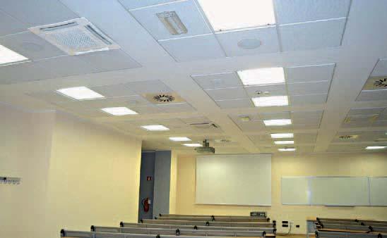
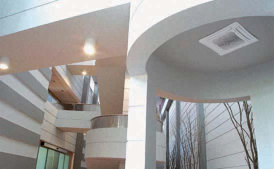
55 MD-600 Diffuser

56 Air Conditioning - ECM Cassette Fan Coil Units SYSTAR - EX - 09/12 COD. A G/09/12 Sabiana s.p.a. via Piave, Corbetta Milano Italy phone r.a. / / fax / info@sabiana.it
SkyStar SK. Cassette Fan Coil Unit with Asynchronous Motor
 SkyStar SK Cassette Fan Coil Unit with Asynchronous Motor Innovating and beautiful design, seven different sizes, high control flexibility, easy maintenance: the SkyStar chilled water Cassette is the result
NEW. SkyStar SkyStar ECM. Cassette Fan Coil Units. consumption ECM motors. Low energy. Air Conditioning ENVIRONMENTAL COMFORT
 NEW energy consumption ECM motors Air Conditioning ECM Cassette Fan Coil Units ISO 9001 - Cert. n 0545/4 Unit heaters Radiant panels Fan coils Air handling units Flues ENVIRONMENTAL COMFORT CONTENTS Introduction
consumption ECM motors NEW Low energy Cassette Fan Coil Units YHK ECM YHK
 NEW energy consumption ECM motors ECM Cassette Fan Coil Units www.eurovent-certification.com www.certiflash.com CONTENTS Introduction Page 3 Main components Page 4 EUROVENT Certifications Page 5 Emissions
Product is subject to and complies with Regulation (UE) N.327/2011. cert. n Fan Coil Unit Cassette SkyStar Jumbo ECM. technical catalogue
 N.327/2011. cert. n Fan Coil Unit Cassette SkyStar Jumbo ECM. technical catalogue") cert. n. 0545 Product is subject to and complies with Regulation (UE) N.327/2011 Fan Coil Unit Cassette SkyStar Jumbo ECM technical catalogue SkyStar Jumbo ECM Table of contents SkyStar Jumbo ECM TABLE
cert. n. 0545 Product is subject to and complies with Regulation (UE) N.327/2011 Fan Coil Unit Cassette SkyStar Jumbo ECM technical catalogue SkyStar Jumbo ECM Table of contents SkyStar Jumbo ECM TABLE
Carisma Fly Carisma Fly-ECM. Made in. Italy. High Wall Fan Coil. Air Conditioning ENVIRONMENTAL COMFORT
 Made in Italy Air Conditioning High Wall Fan Coil -ECM QUALITY MANAGEMENT SYSTEMS ISO 9001 - Cert. n 0545/5 www.eurovent-certification.com www.certiflash.com ENVIRONMENTAL COMFORT CONTENTS Introduction
NEW. MB control board. communication protocol. for Modbus. Air Conditioning Carisma CRSO High Pressure Fan Coil Units
 NEW MB control board for Modbus communication protocol Compliant with ERP 0 Regulation (EU) No. 7/0 Quality management systems ISO 900 Cert. n 0/ www.eurovent-certification.com www.certiflash.com Air Conditioning
Carisma Fly. Made in. Italy. Wall-mounted Fan Coil. Air Conditioning ENVIRONMENTAL COMFORT.
 Made in Italy Air Conditioning Wall-mounted Fan Coil QUALITY MANAGEMENT SYSTEMS ISO 9001 - Cert. n 0545/5 www.eurovent-certification.com www.certiflash.com ENVIRONMENTAL COMFORT CONTENTS Introduction Version
SkyStar SK-ECM. Cassette Fan Coil Unit with EC Brushless Electronic Motor and Inverter Board
 SkyStar SK-ECM Cassette Fan Coil Unit with EC Brushless Electronic Motor and Inverter Board The SkyStar SK-ECM series, available in 5 models, uses an innovative brushless synchronous permanent magnet electronic
High wall fan coils Climmy FHW/FHW-ECM. Technical Catalogue
 High wall fan coils Climmy FHW/FHW-ECM Technical Catalogue Versions and Main components MODELS WITHOUT ELECTRIC HEATER All versions are available without valves, with 2 way valve or with 3 way valve fitted
Air Conditioning Carisma CRS High Pressure Fan Coil Units.
 Air Conditioning Carisma CRS High Pressure Fan Coil Units Quality management systems ISO 900 Cert. n 0/ www.euroventcertification.com www.certiflash.com INTRODUCTION In line with innovative trends and
SABIANA ENVIRONMENTAL COMFORT. Air Conditioning Futura Fan Coil Units ICIM
 Air Conditioning Fan Coil Units ICIM ISO 900 - Cert. n 0545/2 Unit heaters Radiant panels Fan coils Air handling units Flues SABIANA ENVIRONMENTAL COMFORT Sabiana is the fan coil that continues the Sabiana
NEW GREEN TECHNOLOGY
 NEW GREEN TECHNOLOGY - suitable for all heating systems Magnetic Boiler installed in all fan coils - no need for external devices! A c t i v e G r e e n S w e d e n A B ACTI VE Operation limits This technology
NEW. Wall Controls. Air Conditioning Ceiling Air Conditioning Elegant. Cert. n 0545
 NEW Wall Controls Cert. n 0545 Air Conditioning Ceiling Air Conditioning Elegant CONTENTS Page Introduction 3 Main components 4 Dimension, Weight, Water content 5 Main technical figures 6 Working conditions
Application guide. ARMONIA ARMONIA EC 1,3-11 kw. Chilled water cassette Chilled water cassette - EC motor ARMONIA-AGU-1010-E
 Application guide ARMONIA ARMONIA EC 1,3-11 kw Chilled water cassette Chilled water cassette - EC motor ARMONIA-AGU-1010-E TABLE OF CONTENTS APPLICATION GUIDE Ref : ARMONIA-AGU-1010-E ARMONIA Introduction
The Sabiana. of Fan Coil
 The Sabiana family of Fan Coil Range Basics A complete range of fan coils for use with Hot water for heating and chilled water for cooling Eurovent Certified Typical Applications Schools Hotels Commercial
UniTrane Terminals. High Wall Fan Coil: W-Line Ducted Fan Coil: D-Line Blower coil: B-Line. Product Presentation September 2016
 UniTrane Terminals High Wall Fan Coil: W-Line Ducted Fan Coil: D-Line Blower coil: B-Line Product Presentation September 2016 Agenda Product overview Key features Product range Controls Emissions Accessories
SABIANA ENVIRONMENTAL COMFORT. Air Conditioning Ceiling Air Conditioning Elegant
 Air Conditioning Ceiling Air Conditioning Elegant ISO 00 - Cert. n 0/ Unit heaters Radiant panels Fan coils Air handling units Flues SABIANA ENVIRONMENTAL COMFORT Air Conditioning SABIANA ENVIRONMENTAL
YFCN Fan Coil Unit centrifugal fan
 YFCN Fan Coil Unit centrifugal fan 2 & 4 pipe system A complete range from 0.7 kw to 7.4 kw Wired controls JWC-3V Remote three speeds controller JWC-T JWC-3V + Electronic thermostat and Summer/Winter switch
QZHW Fan Coil Unit. Key features. Specifications
 Key features High wall installation Cooling ( pipes) Low noise level Electrical heating coil ECM version for low energy consumption QZHW is a high wall fan coil unit available in sizes and many different
QFDK "ägir II" chilled water cassette
 Key features Chilled water cassette Cooling ( pipes) and heating (4 pipes or electrical heating) ECM version for low energy consumption Beautiful design, six different sizes, high control flexibility,
DUCTED UNITS EBH EDS INTEGRATED COMFORT SYSTEMS
 EN DUCTED UNITS EBH EDS INTEGRATED COMFORT SYSTEMS EBH EDS EBH EDS HIGH PRESSURE UNITS EBH high pressure ducted units and EDS Double Skin units, thanks to their high pressure fan decks, permit to satisfy
ECM Technology. Technology. Features. Advantages (compared to traditional brushed motors) Power consumption: YFCN versus YFCN-ECM (W/kW)
 Power consumption: YFCN versus YFCN-ECM (W/kW)") york air-conditioning products ECM Technology Running costs. Energy consumption. Life cycle. These are 3 issues that are becoming more and more important in the choice of Fan Coil Units. With these criteria
york air-conditioning products ECM Technology Running costs. Energy consumption. Life cycle. These are 3 issues that are becoming more and more important in the choice of Fan Coil Units. With these criteria
UniTrane Ductable Units D-line and B-Line
 UniTrane Ductable Units D-line and B-Line Discover the new UniTrane Ductable Units The ideal air-conditioning solutions for your building Air-conditioning plays an important role in the comfort level in
CASSETTE UNIT. Comfort Circle
 CASSETTE UNIT Comfort Circle Comfort Circle cassette unit All-round comfort With today's energy prices, building owners are increasingly aware of the need for an efficient climate system to heat or cool
Conditioning your ambient, maximising your comfort.
 Centrifugal fan coils for surface mounting or recessed installation. Cooling capacities from 0,6 to 7,6 kw and heating capacity from 0,8 to 9 kw. Air flow from 100 to 1500 m 3 /h. Cassette with radial
QZB "Standard" comfort fan coil
 Key features Vertical or horizontal installation Concealed installation or with decorative cabinet Cooling ( pipes) and heating ( pipes or electrical heating) ECM version for low energy consumption The
TECHNICAL MANUAL YEFB HIGH PRESSURE DUCTED UNIT
 1. GENERAL INFORMATION 1.1 Applications page 2 1.2 Operation» 2 1.3 Performances» 2 1.4 Product range» 2 1.5 Selection software» 2 2. DIMENSIONS AND WEIGHTS» 3 3. COMPONENTS 3.1 Structure» 4 3.2 Coils»
UCS UCS/M UCS/H UCS900
 EN UCS UCS/M UCS/H UCS900 EST EST (Energy Saving Technology) is applied to the EURAPO fan coil units and cassette units. It permits to obtain extremely low electrical absorption and a continuous modulation
DUCTIMAX 2-8 kw. Medium available static pressure ducted hydronic units. Duct unit DUCTIMAX
 Duct unit DUCTIMAX Medium available static pressure ducted hydronic units DUCTIMAX - 8 kw NEW PRODUCT JUNE 05 Performance and compactness in recessed ceiling installations ERGO Supervision Plus -pipe system
Conditioning your ambient, maximising your comfort.
 Centrifugal fancoils for surface mounting or recessed installation. Cooling capacity from 0,6 to 7,6 kw and heating capacity from 0,8 to 9 kw. Air flow from 100 to 1500 m3/h. Cassette with radial fan.
QTS SELECTION TECHNICAL BOOKLET
 EN QTS SELECTION TECHNICAL BOOKLET Bi2 FAN RADIATORS AND FAN COILS Italian company established in 1956 2 Bi2 Bi2 TABLE OF CONTENTS 1 Range of system terminals... 6 1.1 Cabinet system terminals... 6 1.2
Blower-YEFB-020-3R-1maxVel
 YEFB DUCTED UNIT GENERAL FEATURES Structure It is made of 1,0 mm thick galvanised steel. Despite this thickness, a special tool for production allowed to keep a good stiffness, in order to reduce the risk
SIGMA PRISMA LOW BODY CONCEALED
 EN SIGMA PRISMA LOW BODY CONCEALED EST EST (Energy Saving Technology) is applied to the EURAPO fan coil units and cassette units. It permits to obtain extremely low electrical absorption and a continuous
30RB Air-Cooled Liquid Chillers. Nominal cooling capacity 8-14 kw. Features. Quiet operation
 Air-Cooled Liquid Chillers www.eurovent-certification.com www.certiflash.com Quality Management Systems 0RB 008-05 Nominal cooling capacity 8- The new generation of Aquasnap liquid chillers was designed
CUMULUS CUMULUS. Key figures. Construction. Function Integrated chilled beams
 Integrated chilled beams Key figures Connections: 1x mm, 2x mm Airflow: 5-60 l/s Pressure range: 40 - Pa Size: 293 x 200 mm (WxH) Length: 1192 or 1792 mm Total effect: up to 1200W Cumulus is available
Units for suspended ceilings
 X X testregistrierung Units for suspended ceilings Type, hinged induced air grille, water connections Active chilled beam with two-way air discharge and horizontal heat exchanger, suitable for grid ceilings
FHE FHE. Dehumidifiers for radiant cooling systems with heat recovery. Versions
 Dehumidifiers for radiant cooling systems with heat recovery 50 The dehumidifiers with heat recovery of high efficiency series were designed to provide dehumidification and fresh air in a residential area
System architecture. Air treatment Index
 System architecture Air treatment Index 88 Index Chilled-water air treatment units Type Range Cooling capacity, kw Heating capacity, kw Air flow, l/s Chilled-water terminal units Cassette Cabinet Concealed
Cassette units Model Comfort Circle. - heating - cooling - ventilation
 Cassette units Model Comfort Circle - heating - cooling - ventilation Cassette unit: Comfort Circle A comfortable room and climate are pleasant to work in and may also entice visitors to lengthen their
SLS 1202 to With or without total heat recovery. u Air Cooled Screw Chillers. 262 to 916 kw. Engineering Data Manual
 u Air Cooled Screw Chillers SLS 1202 to 4004 With or without total heat recovery 262 to 916 kw Engineering Data Manual EDM SLS407-A.4GB Date : December 2008 Supersedes : TM SLS407-A.3GB/11.06 Specifications
All side discharge units are having high pressure switch (LP switch- Optional) and time delay relay. Compressors are scroll type, Copeland make.
 and time delay relay. Compressors are scroll type, Copeland make.") All outdoor units are designed to perform satisfactorily at 52 C, with the option of either top discharge condensing units, with Copeland reciprocating scroll compressors. All top discharge condensing
All outdoor units are designed to perform satisfactorily at 52 C, with the option of either top discharge condensing units, with Copeland reciprocating scroll compressors. All top discharge condensing
Premium Efficiency Heat Recovery Unit. D-AHU Modular L. Air Handling Units
 Premium Efficiency Heat Recovery Unit D-AHU Modular L Air Handling Units About Daikin Our promise is to ensure that customers can depend on Daikin for the ultimate in comfort, so that they are free to
Galletti IWC THE HYDRONIC CASSETTE UNIT PAR EXCELLENCE A guide to choosing Create value to design better
 www.galletti.it Galletti IWC THE HYDRONIC CASSETTE UNIT PAR EXCELLENCE A guide to choosing 2012 Create value to design better A guide to choosing The group It s 1961 and Galletti with its Jolly copper
SPECIFICATION GUIDE FLEXAIR. Possibility to add auxiliary heaters: Gas, Electrical Heater, Hot Water Coil Possibility to add Heat Recovery Module
 SPECIFICATION GUIDE FLEXAIR Air-cooled packaged Rooftop unit Cooling only or Heat Pump Nominal cooling capacity: 85 to 234 kw Nominal heating capacity: 83 to 226 kw Possibility to add auxiliary heaters:
30RB Air-Cooled Liquid Chillers PRODUCT SELECTION DATA. Easy and fast installation. Compact, reliable and efficient
 PRODUCT SELECTION DATA Easy and fast installation Compact, reliable and efficient Class A variable speed circulator available Air-Cooled Liquid Chillers 0RB 008-015 CARRIER participates in the ECP programme
Bi2 4tubes * SLR 4T Fan coil radiator for heating and cooling at the same time. FEATURES. Cools, Dehumidifies, Heats and Filters
 Bi2 4tubes * SLR 4T Fan coil radiator for heating and cooling at the same time. FEATURES Cools, Dehumidifies, Heats and Filters Simultaneous Cooling + Heating Double HE Coil AC Motor Version with heating
Energy-efficient heat source provides comfort in large rooms
 AIR HEATER NOZ NOZ air heater Energy-efficient heat source provides comfort in large rooms When it comes to providing large, and often high buildings, with the best possible source of efficient heating
a-life Hydronic terminals Fan-coil for professional applications, with cabinet or built-in version 1,50-7,50 kw <<< BACK INDEX

Ceiling swirl diffusers
 X X testregistrierung Ceiling swirl diffusers Type Plenum box with damper blade and square diffuser face Horizontal swirling air discharge For comfort zones, with fixed air control blades Circular and
Fans Air Handling Units Air Distribution Products Fire Safety Air Curtains and Heating Products Water terminals SYSWALL. Wall mounted fan coil units
 Fans Air Handling Units Air Distribution Products Fire Safety Air Curtains and Heating Products Water terminals SYSWALL Wall mounted fan coil units SYSWALL Wall mounted fan coil units With a tangential
Fan Coil Range HYDRONIC TERMINALS
 Fan Coil Range HYDRONIC TERMINALS This document can be subjected to variations. Descriptions, performance data, images and diagrams are indicative only. For further information contact Climaveneta Comunications/Marketing
Ceiling swirl diffusers
 X X testregistrierung Ceiling swirl diffusers Type Plenum box with damper blade (optional) Horizontal swirling air discharge With very low sound power level for comfort zones, with fixed air control blades
CWX 6 - CWX 8 - CWX 10 CASSETTE TYPE TERMINAL UNIT
 TECHNICAL INSTRUCTIONS CWX 6 - CWX 8 - CWX 10 CASSETTE TYPE TERMINAL UNIT Cooling Heating CWX 6 2 pipes 6.00 kw 7.70 kw CWX 8 2 pipes 8.00 kw 10.50 kw CWX 10 2 pipes 9.92 kw 13.00 kw November 2008 10 12
NEW RANGE OF WARM AIR CURTAINS
 NEW RANGE OF WARM AIR CURTAINS stay connected and informed in real time www.france-air.com CONTENTS SELECTION GUIDE 3 HARMONY ONE EVO Compact single-phase warm air curtain 4 REGULATION 5 HARMONY Visible
Units for suspended cei lings
 . X X testregistrierung Units for suspended cei lings Type, hinged induced air grille, water connections Chilled Beams No. 09.2.432 Eurovent certification HYGIENISCH GETESTET V DI 6022 Tested to VDI 6022
TOPAZ ADIABATIC COOLER
 TOPAZ ADIABATIC COOLER CONTENT Page Principle and operation 2 General description and benefits 3 TECHNICAL DOCUMENTATION Manufacturing details Options 4 6 Drawings and dimensions 7 On site lay out 8 Technical
Controls for fan coil units and cassettes
 for Fan Coils. Technical Catalogue. for fan coil units and cassettes Stand alone or Modbus communication Built-in, wall-mounted and IR remote Power supply 230V 2 pipes and 4 pipes system Electrical heating
30GH Air-Cooled Liquid Chillers 30GH Nominal cooling capacity kw
 Air-Cooled Liquid Chillers Nominal cooling capacity 21-94 kw Carrier is participating in the Eurovent Certification Programme. Products are as listed in the Eurovent Directory of Certified Products. The
Homepage > Products > Decentralised ventilation systems > Vertical units > Type FSL-V-ZAB/SEK FSL-V-ZAB/SEK
 Homepage > Products > Decentralised ventilation systems > Vertical units > Type FSL-V-ZAB/SEK FSL-V-ZAB/SEK SUPPLY AND EXTRACT AIR UNIT WITH HEAT EXCHANGER AND HEAT RECOVERY, SECONDARY AIR OPTION, FOR
KOG LN. Low Noise Chilled Water Cassettes Models 09, 12 & to 6.10kW to 5.10kW. 330 to 920 m3/h
 KOG LN Low Noise Chilled Water Cassettes 09, 12 & 18 1.70 to 6.10kW 1.58 to 5.10kW 330 to 920 m3/h KOG LN 9 / KOG LN 12 / KOG LN 18 Design Features Introduction The new low noise chilled water cassettes
SIMPLICITY FULL MODULARITY?
 D E S I G N I N G I N N O V A T I V E S O L U T I O N S AIR CONDITIONING & HEATING SOLUTIONS OR SIMPLICITY FULL MODULARITY? IDROFAN, BECAUSE YOU SHOULD NOT HAVE TO CHOOSE. Hydronic ducted fan coils Cooling
GHE Dehumidifiers for radiant cooling systems with heat recovery
 Dehumidifiers for radiant cooling systems with heat recovery The dehumidifiers with heat recovery of high efficiency series were designed to provide dehumidification and fresh air in a residential area
CMA TECHNICAL MANUAL CONDENSING UNITS FOR OUTDOOR INSTALLATION O L S A F RA N
 E S A RE F R E IG RA N T G TECHNICAL MANUAL -FRIEND Y CONDENSING UNITS FOR OUTDOOR INSTALLATION O L CMA C 2 The manufacturer declines all the responsabilities regarding inaccuracies contained in this manual,
COMFORT HYDRONIC TERMINALS
 COMFORT HYDRONIC TERMINALS i i-chd NEW GENERATION CASSETTE WITH EC HIGH EFFICIENCY MOTOR. CENTRIFUGAL FAN WITH CONTINUOUS AIR FLOW REGULATION AND SPEED MODULATION. ENERGY CONSUMPTION REDUCED BY MORE THAN
ED.X F Kc DIRECT EXPANSION CLOSE CONTROL UNITS WITH REMOTE CONDENSERS AND ADDITIONAL CHILLED WATER FREE COOLING COIL
 DIRECT EXPANSION CLOSE CONTROL UNITS WITH REMOTE CONDENSERS AND ADDITIONAL CHILLED WATER FREE COOLING COIL COOLING CAPACITY FROM 20,8 TO 93,3 kw ED.X 1462 F U Kc 72 FC The range of direct expansion close
CWX 3 - CWX 5 CASSETTE TYPE TERMINAL UNIT. Cooling
 TECHNICAL INSTRUCTIONS CWX 3 - CWX 5 CASSETTE TYPE TERMINAL UNIT Cooling Heating CWX 3 pipes.60 3.9 pipes + electric heating.08.96 +.5 pipes.08.5 CWX 5 pipes.70 5.70 pipes + electric heating.3 5.3 +.50
VMA-VMB NOVA AIR HEATERS. NoVa air heaters
 VMA-VMB NOVA AIR HEATERS NoVa air heaters PRODUCT FACTS PRODUCT The Novenco NoVa air heaters are water-based units with hot-water heating coils and axial flow fans fitted in cabinets. VMA for 10-20 C cooling
FAN COIL UNITS LASER / LOW BODY / CONCEALED
 SAPHIR TECHNICAL LITERATURE FAN COIL UNITS LASER / LOW BODY / CONCEALED Energy Saving Technology EST (Energy Saving Technology) is applied to the Johnson Controls fan coil units and cassette units. It
Heating / Air Conditioning Energy Heat Recovery Units ENVIRONMENTAL COMFORT
 Heating / Air Conditioning Energy Heat Recovery Units ISO 9001 - Cert. n 0545/4 Unit heaters Radiant panels Fan coils Air handling units Flues ENVIRONENTAL COFORT Heating Air Conditioning ENVIRONENTAL
technical data Fan coil unit FWB small duct unit
 technical data Fan coil unit FWB small duct unit TABLE OF CONTENTS FWB 1. Nomenclature ---------------------------------------------------------------------- 2 2. Features -----------------------------------------------------------------------------
Also available with the new i-life R-Slim inverter and radiant panel version. Perfect comfort. Silent operation. Real energy savings
 The new i-life Slim fan coil, with inverter technology for heating, cooling and dehumidifying. Its elegant design with only 13 cm depth makes i-life Slim the perfect solution for residential applications.
Technical Manual. New Water Cassette. Series BREZZA DOUBLE
 Technical Manual New Water Cassette Series BREZZA DOUBLE AERTESI srl Cassetta BREZZA DOUBLE Tecnical manual AER.MT.I.BREDOPPIA.000.02.15 Pag.2 INDEX 1-INTRODUCTION 4 2- WORKING CONDITION LIMITS..4 3- COANDA
COMFORT APPLICATION HYDRONIC TERMINALS ELEGANCE AND DESIGN FOR YOUR RESIDENTIAL COMFORT
 COMFORT APPLICATION HYDRONIC TERMINALS ELEGANCE AND DESIGN FOR YOUR RESIDENTIAL COMFORT climaveneta.com COMFORT APPLICATION HYDRONIC TERMINALS between elegance, comfort and energy savings Conceived to
SPECIFICATION GUIDE NEOSYS. Air-cooled Liquid Chiller for outdoor installation (NAC) Nominal cooling capacity: 200 to 460 kw
 Nominal cooling capacity: 200 to 460 kw") SPECIFICATION GUIDE NEOSYS Air-cooled Liquid Chiller for outdoor installation (NAC) Nominal cooling capacity: 200 to 460 kw Air-to-water Heat Pump for outdoor installation (NAH) Nominal cooling capacity:
SPECIFICATION GUIDE NEOSYS Air-cooled Liquid Chiller for outdoor installation (NAC) Nominal cooling capacity: 200 to 460 kw Air-to-water Heat Pump for outdoor installation (NAH) Nominal cooling capacity:
COOLROW Close control air conditioners for In-Row installation Cooling Capacity: kw
 COOLROW Close control air conditioners for In-Row installation Cooling Capacity: 14 61 Available in versions equipped with: - BLDC inverter scroll compressor on board of the unit - Chilled water feeding
F series close control air conditioners exploit the indirect FREE COOLING system with adiabatic cooling to ensure high system energy savings.
 F series close control conditioners exploit the indirect FREE COOLING system with adiabatic cooling to ensure high system energy savings. 38 The F series units are the ideal solution to cool in systems
> HGA AIR - WATER HEAT PUMPS FOR OUTDOOR INSTALLATION. Available range. Unit description. Options. Accessories
 > HGA AIR - WATER HEAT PUMPS FOR OUTDOOR INSTALLATION Available range Unit type IP Reversible heat pump (reversible on the refrigerant side) ECO-FRIENDLY REFRIGERANT GAS Versions (heat recovery) VB Base
CRIMSON & CRIMSON MAX
 High efficiency water/water and geothermal heat pumps 5 114 General High efficiency water/water and geothermal heat pumps. Ideal for heating, cooling and production of domestic hotwater with total or partial
GHE GHE. Dehumidifiers for radiant cooling systems with heat recovery VERSIONS ACCESSORIES
 Dehumidifiers for radiant cooling systems with heat recovery The dehumidifiers with heat recovery of high efficiency series were designed to provide dehumidification and fresh air in a residential area
FCX FAN COIL SILENT & EFFICIENT. Floor, ceiling & ducted installation Applicable with VMF management system, Plasmacluster filter option
 FCX FAN COIL SILENT & EFFICIENT Floor, ceiling & ducted installation Applicable with VMF management system, Plasmacluster filter option THE AERMEC FAN COILS Fan coils and Aermec: a combination where the
CMA CONDENSING UNITS FOR OUTDOOR INSTALLATION INSTALLATION AND OPERATION MANUAL
 CMA CONDENSING UNITS FOR OUTDOOR INSTALLATION ECO-FRIENDLY REFRIGERANT GAS INSTALLATION AND OPERATION MANUAL Dear Customer, Thank you for having purchased a FERROLI product. It is the result of many years
CHILLED BEAM CASSETTE IQ STAR LYRA
 CHILLED BEAM CASSETTE IQ STAR LYRA TECHNICAL CATALOGUE 2 IQ Star LYRA Chilled beam cassette - Technical catalogue IQ STAR LYRA CHILLED BEAM CASSETTE The LYRA chilled beam cassette is a compact chilled
NRP MULTIPURPOSE HEAT PUMPS 2 AND 4-PIPE SYSTEMS PLUS PRODUCTION OF DOMESTIC HOT WATER
 NRP MULTIPURPOSE HEAT PUMPS AND 4-PIPE SYSTEMS PLUS PRODUCTION OF DOMESTIC HOT WATER Multipurpose air cooled units with axial fans. For external installation. High efficiency version. NRP MULTIPURPOSE
SPECIFICATIONS CWC - 2P / 4P CWC 020 CWC 030 CWC 040 CWC 050 CWC 070 CWC
 APPLICATION GUIDE CHILLED WATER CASSETTE CWC - P/4P English/03-005 INDEX Index AGU CWC-P/4P General Description Specifications Performances tables Sound levels Options Dimensions Unit installation Electrical
ART-U 1-4 kw. Design fan coil unit with a minimum depth of 10 cm only and BLDC motor. Fan coil ART-U PLUS. Design-driven innovation NEW
 Fan coil ART-U NEW PRODUCT Design fan coil unit with a minimum depth of 10 cm only and BLDC motor ART-U 1-4 kw Available from SEPTEMBER 2018 Design-driven innovation BLDC motor Tangential fan Supervision
THIN PROFILE CENTRIFUGAL FAN COIL UNITS SLIM
 THIN PROFILE CENTRIFUGAL FAN COIL UNITS SLIM 0,7 kw 5,2 kw 1,6 kw 10,2 kw 130 m 3 /h 830 m 3 /h SLIM SLIMxx0 vertical with cabinet bottom vertical Available also with feet SLIMxx8 SLIMxx5 SLIMxx4 SLIMxx9
ELFODuct MP. Technical Bulletin. New generation horizontal and vertical built-in water-source ductable terminal for medium and large systems
 Technical Bulletin BT13F002GB-04 ELFODuct MP New generation horizontal and vertical built-in water-source ductable terminal for medium and large systems ELFODUCT MP 15-71 SERIES SERIES RECOMMENDED FOR
Refrigerant R407C CW-AR. 2.4 to 3.1kW. Water Source Heat Pumps - Vertical Mounting Version Models 07 to to 2.7kW
 Refrigerant R407C CW-AR Water Source Heat Pumps - Vertical Mounting Version Models 07 to 12 2.4 to 3.1kW 1.9 to 2.7kW Some advantages... RAL 9010 painted cabinet 3-fan speeds G2 filter is supplied as
EHH SERIES DRAW THROUGH FAN COILS CFM
 EHH SERIES DRAW THROUGH FAN COILS 400-5000 CFM TABLE OF CONTENTS TABLE OF CONTENTS 2 INTRODUCTION 3 GUIDE SPECIFICATIONS 4 UNIT OVERVIEW 6 TECHNICAL DATA 8 DIMENSIONS 10 COMPUTER SELECTION 11 GEMCOOL PROFILE
Energy. The Energy ducted units have been designed. Heat Recovery Unit
 Energy Heat Recovery Unit The Energy ducted units have been designed to allow energy savings in the ventilation systems of public and private environments, such as bars, restaurants, offices, shops, etc.,
Optimal work climate with open doors. Industrial air curtains Model IndAC
 Optimal work climate with open doors Industrial air curtains Model IndAC Industrial air curtain Optimal work climate During loading and unloading the door remains open, without the indoor climate being
Helios. Unit Heater. Thickness 1 mm. Diameter 22 mm. Pitch 2,5 mm. Fin 0,12 mm
 Thickness 1 mm Diameter 22 mm Pitch 2, mm Helios Unit Heater Fin 0,12 mm The HELIOS Sabiana unit heaters, built with the same criteria of sturdiness and safety that define all Sabiana products, stand out
Elegance and design for your residential comfort
 Elegance and design for your residential comfort between elegance, comfort and energy savings Conceived to make every kind of residential environment more comfortable, the new i-life Slim fan coil integrates
Ceiling diffusers. Type DLQL
 X X testregistrierung Type Horizontal one-way air discharge Horizontal two-way air discharge Horizontal four-way air discharge Horizontal duct connection For horizontal one-way to four-way air discharge,
PRODUCT GUIDE
 PRODUCT GUIDE 01.2017 Cooling Heating CHAPTER 1 AIRCOOLED LIQUID CHILLERS AND HEAT PUMPS FOR RESIDENTIAL & LIGHT COMMERCIAL APPLICATION Power (kw) Page IACAK/II/WP 101.5 106 0 58 115 A CLASS energy efficiency
TopVent Design Handbook
 TopVent Design Handbook Recirculation Units and Supply Air Units for Heating and Cooling High Spaces TopVent Content TopVent DHV Recirculation unit for heating high spaces TopVent NHV Recirculation unit
1 VICTRIX ZEUS Superior kw I features
 Wall-hung condensing VICTRIX ZEUS Superior kw I is the new range of wall-hung condensing boilers with 54 litre stainless steel storage tank available in two versions with nominal heat output of 26 kw and
AIR COOLED CHILLERS WITH SCROLL COMPRESSORS AND CENTRIFUGAL FANS
 RAE 1402 C O K AIR R-407C Series RAE... C K Cooling capacity from 81 to 250 kw - 2 circuits The air cooled chillers of RAE C K series, with centrifugal fans, are designed for indoor installation and are
SMART. 4,9 49,5 kw. Air cooled liquid chillers and heat pumps equipped with scroll compressor and axial fans T_SMT_0609_GB
 T_SMT_0609_GB 4,9 49,5 kw Air cooled liquid chillers and heat pumps equipped with scroll compressor and axial fans INDEX SERIES IDENTIFICATION... 3 MODEL IDENTIFICATION... 3 CE CONFORMITY... 3 WORKING
TOTAL HEAT RECOVERY MULTI-PURPOSE HEAT PUMPS
 TOTAL HEAT RECOVERY MULTI-PURPOSE HEAT PUMPS Energy saving thanks to a total recovery p Cooling Heating/DHW h Galletti multi-purpose heat pumps are total recovery units used for a simultaneous hot and