Operation and Installation Manual. GP Series Portable Chillers
|
|
|
- Dominick Woods
- 6 years ago
- Views:
Transcription
1 Operation and Installation Manual GP Series Portable Chillers Part Number: Bulletin Number: WTR3-600 Effective: 10/1/2013
2 Write Down Your Serial Numbers Here For Future Reference: We are committed to a continuing program of product improvement. Specifications, appearance, and dimensions described in this manual are subject to change without notice. ECN No. Copyright 2013 All rights reserved. GP Series Portable Chillers ii
3 Shipping Information Unpacking and Inspection You should inspect your equipment for possible shipping damage. Thoroughly check the equipment for any damage that might have occurred in transit, such as broken or loose wiring and components, loose hardware and mounting screws, etc. In the Event of Shipping Damage According to the contract terms and conditions of the Carrier, the responsibility of the Shipper ends at the time and place of shipment. Notify the transportation company s local agent if you discover damage Hold the damaged goods and packing material for the eamining agent s inspection. Do not return any goods before the transportation company s inspection and authorization. File a claim with the transportation company. Substantiate the claim by referring to the agent s report. A certified copy of our invoice is available upon request. The original Bill of Lading is attached to our original invoice. If the shipment was prepaid, write us for a receipted transportation bill. Advise customer service regarding your wish for assistance and to obtain an RMA (return material authorization) number. If the Shipment is Not Complete Check the packing list as back-ordered items are noted on the packing list. In addition to the equipment itself, you should have: Bill of lading Packing list Operating and Installation packet Electrical schematic and panel layout drawings Component instruction manuals (if applicable) Re-inspect the container and packing material to see if you missed any smaller items during unpacking. If the Shipment is Not Correct If the shipment is not what you ordered, contact the shipping department immediately. For immediate assistance, please contact the correct facility located in the technical assistance section of this manual. Have the order number and item number available. Hold the items until you receive shipping instructions. GP Series Portable Chillers iii
4 Returns Do not return any damaged or incorrect items until you receive shipping instructions from the shipping department. Credit Returns Prior to the return of any material, authorization must be given by the manufacturer. A RMA number will be assigned for the equipment to be returned. Reason for requesting the return must be given. ALL returned material purchased from the manufacturer returned is subject to 15% ($75.00 minimum) restocking charge. ALL returns are to be shipped prepaid. The invoice number and date or purchase order number and date must be supplied. No credit will be issued for material that is not within the manufacturer s warranty period and/or in new and unused condition, suitable for resale. Warranty Returns Prior to the return of any material, authorization must be given by the manufacturer. A RMA number will be assigned for the equipment to be returned. Reason for requesting the return must be given. All returns are to be shipped prepaid. The invoice number and date or purchase order number and date must be supplied. After inspecting the material, a replacement or credit will be given at the manufacturer s discretion. If the item is found to be defective in materials or workmanship, and it was manufactured by our company, purchased components are covered under their specific warranty terms. GP Series Portable Chillers iv
5 Table of Contents CHAPTER 1: SAFETY How to Use This Manual... 7 Safety Symbols Used in this Manual Warnings and Precautions Responsibility... 9 CHAPTER 2: FUNCTIONAL DESCRIPTION Models Covered in This Manual General Description Typical Applications System Limitations Chilled Water Circuit Refrigeration Circuit Standard Features Mechanical Features Electrical Features Refrigeration Features Controller Features Other Features Safety Devices and Interlocks Crankcase Heater High Pressure Cutout Low Pressure Cutout (no switch but done through the transducer) Flow Switch Remote Start/Stop Interlock Optional Features CHAPTER 3: INSTALLATION Uncrating Electrical Connections Process Water Connections Bypass Valve Considerations Galvanic Corrosion Considerations Water Treatment Considerations Condenser Considerations Water-Cooled Chiller Condensers Air-Cooled Chiller Condensers Remote Air-Cooled Chiller Condensers Checking Motor Direction Three-Phase Compressors Water Pumps Condenser Fan Water Reservoir Automatic Water Make-Up Option Initial Start-Up Finishing Setup: Setting Up Passwords CHAPTER 4: OPERATION Panel Buttons, Indicator Lights, and Switches Microprocessor Controller Initial Start-up Status Screens GP Series Portable Chillers v
6 4-4 Access Levels Controller Setpoints Configuration Settings Alarms Optional Communications CHAPTER 5: MAINTENANCE Lubrication Filter Cleaning Maintaining the Condenser Air- and Remote Air-Cooled Chillers Water-Cooled Chillers Maintaining the Evaporator Evaporator Process Piping Y-Strainer Preventative Maintenance Service CHAPTER 6: TROUBLESHOOTING Identifying the Cause of a Problem Non-Controller Related Issues CHAPTER 7: APPENDIX Technical Assistance Parts and Service Department Sales and Contracting Department Specifications Air-Cooled Portable Chillers Water-Cooled Portable Chillers Pump Curves, Flow, and Pressure Considerations Hertz Pump Curves Hertz Pump Curves Remote Air-Cooled Chiller Configurations Typical Ductwork for Air-Cooled Chillers Piping Diagrams GP Series Portable Chillers vi
7 Chapter 1: Safety 1-1 How to Use This Manual Use this manual as a guide and reference for installing, operating, and maintaining your equipment. The purpose is to assist you in applying efficient, proven techniques that enhance equipment productivity. This manual covers only light corrective maintenance. No other maintenance should be undertaken without first contacting a service engineer. The Functional Description section outlines models covered, standard features, and optional features. Additional sections within the manual provide instructions for installation, preoperational procedures, operation, preventive maintenance, and corrective maintenance. The Installation chapter includes required data for receiving, unpacking, inspecting, and setup of the equipment. We can also provide the assistance of a factory-trained technician to help train your operator(s) for a nominal charge. This section includes instructions, checks, and adjustments that should be followed before commencing with operation of the equipment. These instructions are intended to supplement standard shop procedures performed at shift, daily, and weekly intervals. The Operation chapter includes a description of electrical and mechanical controls, in addition to information for operating the equipment safely and efficiently. The Maintenance chapter is intended to serve as a source of detailed assembly and disassembly instructions for those areas of the equipment requiring service. Preventive maintenance sections are included to ensure that your equipment provides ecellent, long service. The Troubleshooting chapter serves as a guide for identification of most common problems. Potential problems are listed, along with possible causes and related solutions. The Appendi contains technical specifications, drawings, schematics, and parts lists. A spare parts list with part numbers specific to your machine is provided with your shipping paperwork package. Refer to this section for a listing of spare parts for purchase. Have your serial number and model number ready when ordering. Safety Symbols Used in this Manual The following safety alert symbols are used to alert you to potential personal injury hazards. Obey all safety messages that follow these symbols to avoid possible injury or death. DANGER indicates an imminently hazardous situation, which, if not avoided, will result in death or serious injury. WARNING indicates a potentially hazardous situation or practice which, if not avoided, could result in death or serious injury. CAUTION indicates a potentially hazardous situation or practice which, if not avoided, may result in minor or moderate injury or in property damage. GP Series Portable Chillers Chapter 1: Safety 7 of 93

8 Hazard Alert Symbol Description/Eplanation Preventative Maintenance High Voltage Hazard. The electrical enclosure is supplied with 3-phase electrical power. Use caution when using or maintaining this product. Cut/Crush Hazard. The air cooled version of this product has high speed rotating fan blades. Use caution when using or maintain this product. Hot Surface Hazard. When the unit operates above 212F (100C) the surface of the unit may reach ecessive temperatures. Use caution when using or maintaining this product. Low Temperature Hazard. This unit can operate at temperatures below 32F (0 C), and as such surfaces within this unit may reach ecessively low temperatures. Use caution when using or maintaining this product. Every si months inspect all electrical connections for secure attachment. For further information see the Maintenance Chapter in this manual Every month inspect the guarding around the fan blade to ensure proper installation and working condition. Every si months inspect all surfaces for signs of heat degradation. If any appear remove panel and verify cause of degradation and repair. Every si months inspect all insulation for proper installation. If any insulation is missing repair/replace as soon as possible. Mandatory Symbol Description/Eplanation Read Operators Manual. This equipment must be operated and maintained by properly trained personnel. The information contained within this manual must be read and understood prior to operating this equipment. Lock Out. This equipment is operated with 3-phase electrical power. Therefore, when performing any maintenance operations we recommend following the local standards for performing a lockout/tag-out procedure. Wear Safety Gloves. This equipment operates above 212F (100C) and its surfaces may reach ecessive temperatures. We recommend that technicians use safety gloves while performing maintenance to protect hands from being eposed to these hot surfaces. GP Series Portable Chillers Chapter 1: Safety 8 of 93
9 1-2 Warnings and Precautions Our equipment is designed to provide safe and reliable operation when installed and operated within design specifications, following national and local safety codes. To avoid possible personal injury or equipment damage when installing, operating, or maintaining this equipment, use good judgment and follow these safe practices: ü Follow all SAFETY CODES. ü Wear SAFETY GLASSES and WORK GLOVES. ü Disconnect and/or lock out power before servicing or maintaining the equipment. ü Use care when LOADING, UNLOADING, RIGGING, or MOVING this equipment. ü Operate this equipment within design specifications. ü OPEN, TAG, and LOCK ALL DISCONNECTS before working on equipment. You should remove the fuses and carry them with you. ü Make sure the equipment and components are properly GROUNDED before you switch on power. ü When welding or brazing in or around this equipment, make sure VENTILATION is ADEQUATE. PROTECT adjacent materials from flame or sparks by shielding with sheet metal. An approved FIRE EXTINGUISHER should be close at hand and ready for use if needed. ü Refrigeration systems can develop refrigerant pressures in ecess of 500 psi (3,447.5 kpa/ bars). DO NOT CUT INTO THE REFRIGERATION SYSTEM. This must be performed by a qualified service technician only. ü Do not restore power until you remove all tools, test equipment, etc., and the equipment and related components are fully reassembled. ü Only PROPERLY TRAINED personnel familiar with the information in this manual should work on this equipment. We have long recognized the importance of safety and have designed and manufactured our equipment with operator safety as a prime consideration. We epect you, as a user, to abide by the foregoing recommendations in order to make operator safety a reality. 1-3 Responsibility These machines are constructed for maimum operator safety when used under standard operating conditions and when recommended instructions are followed in the maintenance and operation of the machine. All personnel engaged in the use of the machine should become familiar with its operation as described in this manual. Proper operation of the machine promotes safety for the operator and all workers in its vicinity. Each individual must take responsibility for observing the prescribed safety rules as outlined. All warning and danger signs must be observed and obeyed. All actual or potential danger areas must be reported to your immediate supervisor. GP Series Portable Chillers Chapter 1: Safety 9 of 93
10 Chapter 2: Functional Description 2-1 Models Covered in This Manual This manual provides operation, installation, and maintenance instructions for air-, water-and remote air-cooled portable chillers. Model numbers are listed on the serial tag. Make sure you know the model and serial number of your equipment before contacting the manufacturer for parts or service. Our portable chiller models are designated by approimate output in kw of cooling (20, 30, 40, 50, through 210) and the cooling method used: -A for air-cooled, -W for water-cooled, and R for remote-air cooled. 2-2 General Description Our portable chillers are reliable, accurate, and easy to use process cooling units. They are available in air-, water-, and remote air-cooled designs in a range of sizes from 20 kw through 210 kw (5 through 60 tons of refrigeration). All are self-contained, fully portable and shipped ready to use. (Remote air-cooled chillers require field installation by qualified technicians.) In the standard configuration the chiller basically consists of a pump, tank, compressor, condenser, evaporator, and a control platform. All of these components, plus the other integral components to maintain the leaving fluid temperature, are described throughout this Chapter as well as Chapters 3 and 4. Standard range of operation is 20ºF to 80ºF (-7ºC to 27ºC) for applications using a water/glycol mi and 45ºF to 80ºF (7º to 27ºC) for water only applications. Typical Applications This series of portable chillers can be used in any application that needs a constant source of cool process water. Typical applications include, but are not limited to, the following: Injection molding Blow molding Etrusion Thermoforming Machine tool Metal plating Thermal spray After-coolers (air compressors, dryers, etc.) Laser Printing (offset, gravure, digita) System Limitations These packaged chillers should be chosen using the following criteria: Process heat load Choose the size of the chiller so that rated capacity is no greater than 10% more than the process heat load. GP Series Portable Chillers Chapter 2: Functional Description 10 of 93
11

12 Refrigeration Circuit Air-, water-, and remote air-cooled refrigerant condensing differ only in the way the compressed gas is condensed to a liquid. Shown below is a water-cooled version. The refrigerant is compressed in the compressor and flows through the discharge line as a gas to the condenser. There it gives up its heat as it condenses to a liquid in the condenser. Liquid refrigerant from the condenser heat echanger flowing in the liquid line passes through a shut-off valve into a filter/dryer that removes moisture and other contaminants. After the filter/dryer the refrigerant passes through a solenoid valve to prevent liquid migration when the compressor is off. A refrigerant sight glass is provided to view the flow of liquid refrigerant, and to view if the system is free of moisture. The refrigerant then passes through the thermal epansion valve, which allows the refrigerant to epand (boil off) and cool (remove the heat from) the fluid inside of the evaporator. From the evaporator the refrigerant gas flows through the suction line back into the compressor. A modulating electronic hot gas bypass valve is used to control cooling capacity during intermittent or partial load conditions. This feature contributes substantially to chiller longevity by eliminating ecessive cycling of the compressor and providing close temperature control. System Control Putting this all together, the controller maintains the desired leaving fluid temperature using multiple inputs to determine if, when and for how long the compressor(s) are on, and if, when, the percent open and for how long the modeling hot gas bypass valve is on. Once the unit s power is enabled and the controller is turned on (see Chapter 4 for more details on the operation of the controller) it verifies there is sufficient fluid level in the tank (if present). If there is not enough fluid in the tank the controller will warn the user, or fill the tank with water from a connected source if equipped with the optional automatic water makeup valve. See Chapter 3 for more information regarding the initial setup and startup of the unit. Once the tank level is satisfied and the start button is pressed, the process pump turns on and provides flow to the process. The controller verifies the flow through the electronic flow switch. If the flow is not established within 10 seconds the controller will alarm and disable the refrigeration circuit. Upon flow verification the controller uses the leaving fluid temperature and the setpoint temperature to determine the operation of the compressor(s). When the leaving fluid temperature is greater than the setpoint plus the compressor on GP Series Portable Chillers Chapter 2: Functional Description 12 of 93
13 differential value the controller will enable the compressor; if equipped with two compressors the controller will enable the one with the least amount of hours. The second compressor will be enabled if the leaving fluid temperature remains above the setpoint plus the compressor on differential value for more than 60 seconds. The hot gas valve is designed to trim the load of one compressor and will modulate in order to meet the desired leaving fluid setpoint via a PID algorithm. After the compressor starts, the hot gas valve is allowed to modulate. The compressor will shut off if the leaving fluid temperature drops below the compressor off differential and the hot gas valve is at 100% for the compressor off delay time. The hot gas will reset to 0% when the compressor is off. There is a compressor anticyle timer that will delay the time between compressor starts to prevent short cycling of the compressor. This is a start to start timer set at 5 minutes. For eample, if the compressor has been running for 5 minutes and shuts off, then the compressor can start immediately if the demand is there. If it has only been running for 2 minutes, then it would not be able to start again for 3 minutes. For a unit with two compressors, the second compressor or lag compressor starts when the lead compressor is on, the hot gas is at 0%, and the leaving fluid temperature is above the setpoint plus the compressor on differential. There is also an adjustable lag compressor on delay timer. Before starting either compressor, the compressor with the least amount of runtime hours is considered the lead compressor and the first to start. When both compressors are running, the compressor with the most hours is considered the lead compressor and is the first to stop. The lead compressor will shut off if the leaving fluid temperature drops below the compressor off differential and the hot gas valve is at 100% for the lead compressor off delay time. The compressor anti-cycle timers are active with the two compressor units. There will be two PID controls running simultaneously for determining the position of the hot gas valve. One PID output will be based on leaving fluid temperature and the other based on a minimum saturated suction temperature for freeze protection. The hot gas valve position will be determined by which output is greater. If it is controlling to the saturated suction temperature to prevent freezing, a warning will display on the screen that the hot gas is in this mode. Once the control goes back to setpoint control, the warning will disappear. The saturated suction temperature is calculated from the suction pressure and the type of refrigerant. The discharge pressure is controlled using an analog output signal to drive a fan for aircooled units or a water regulating valve for water-cooled units. The output signal is determined from a PID algorithm using a discharge pressure transducer as the process variable. The VFD or water regulating valve is controlled from the analog output to an adjustable discharge pressure setpoint. The analog output starts at the initial discharge pressure start % for a given time delay (discharge pressure hold). After the time delay, it will control to the discharge pressure setpoint via the PID control. There is also a setting to control the discharge pressure to the most efficient value. 2-3 Standard Features Mechanical Features Compressor Hermetic scroll compressors. Evaporator Stainless steel copper brazed plate evaporators. GP Series Portable Chillers Chapter 2: Functional Description 13 of 93
14 Air-Cooled Condenser Aluminum fin/ tube with washable filters, packaged units only. Variable speed fan control standard for all remote air cooled condensers and GPAC70 through 210. Optional on GPAC20 through 50. Water-Cooled Condenser Tube-in-tube condensers (GPWC20 GPWC50), Shell-andtube condensers (GPWC70 GPWC210). All come with electronic cooling water regulating valves. Remote Air-Cooled Condenser Aluminum fin/tube with low ambient control down to 20ºF (-29ºC) via variable-speed fan(s). Reservoir GP20 and GP30 models use a 20 gallon (75 liter) polyethylene tank, GP40 and GP50 models use a 40 gallon (150 liter) polyethylene tank, GP70 thru GP105 models use a 70 gallon (265 liter) polyethylene tank, GP140 thru GP210 models use a 140 gallon (530 liter) polyethylene tank. 304SS is available as an option for all sizes. Piping Non-ferrous chilled water piping Pump ODP motors (TEFC Optional) horizontally mounted stamped stainless steel construction. Other Mechanical Features Low process water thermal flow switch NEMA-rated fan motor(s) on air-cooled models Galvanized structural steel frame, polyester powder coat painted cabinetry Internal process water bypass valve for system protection only Fully insulated refrigeration and process water piping 20 mesh Y strainer on process water piping into the evaporator Tank level indication via operator interface Pump pressure indication via operator interface Electrical Features Fully accessible NEMA 4/12-style electrical control enclosure Single-point power and ground connection Non-fused disconnect switch, lockable Branch circuit protection /3/60, 460/3/60, 575/3/60 volt; 400/3/50 volt Refrigeration Features HFC-410a refrigerant Electronic modulating hot gas bypass capacity control High refrigerant pressure cutout switch (manual reset) Suction and discharge pressure transducers. High refrigerant pressure spring actuated relief valve GP Series Portable Chillers Chapter 2: Functional Description 14 of 93
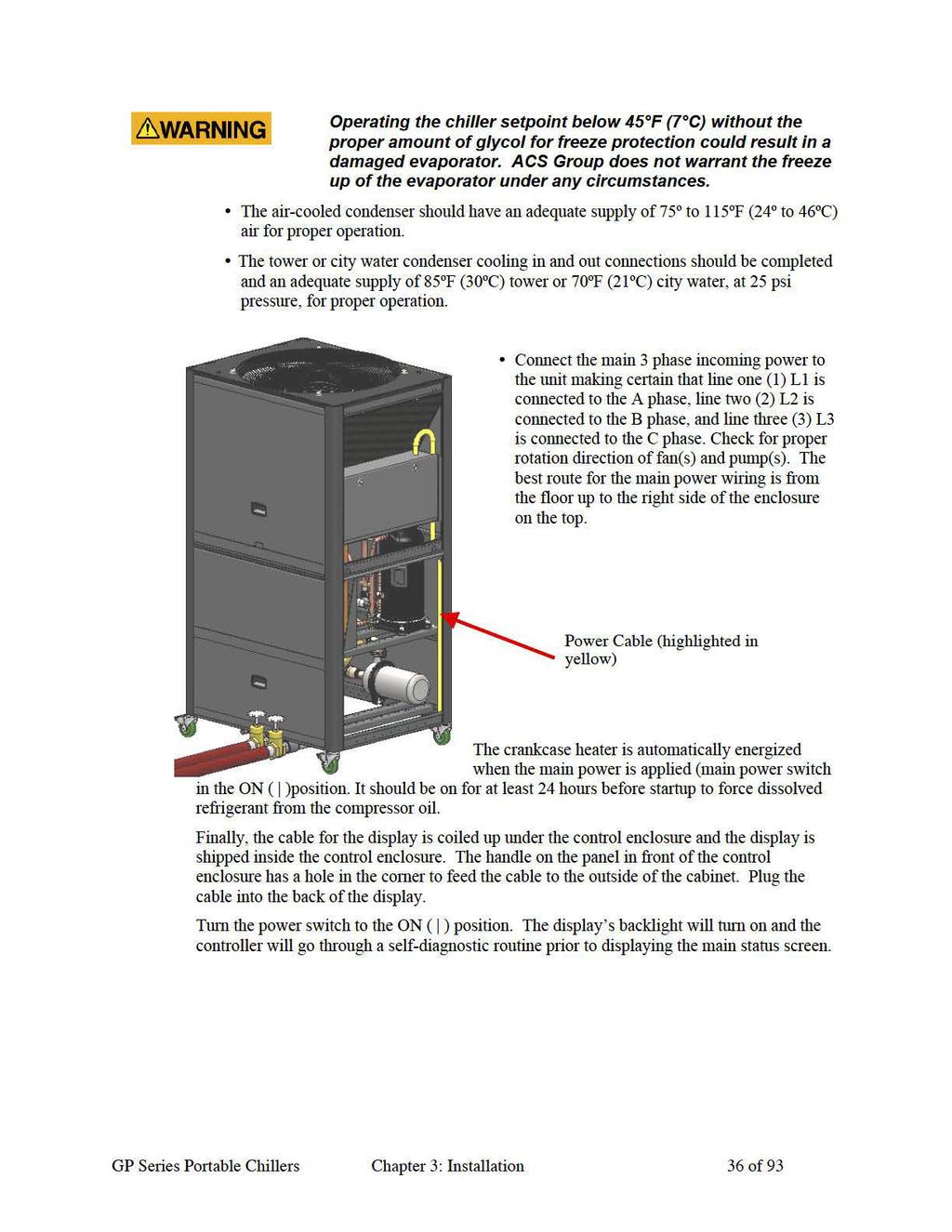
15 Multiple refrigeration access ports Liquid line shut-off ball valves Filter-dryer Sight glass Eternally equalized thermal epansion valve Liquid line solenoid Compressor crankcase heater Controller Features Off-the-shelf microprocessor-based PID controller with To Process, From Process and Set Point readout Time delay for proof of water flow/pressure (models w/pump only) Low refrigerant pressure time delay for low ambient start-up on remote air-cooled and air-cooled chillers with the variable-speed fan option. 8 line 22 character display with status, alarm, and service screens Display has magnetic back and can be mounted anywhere. Other Features One year labor warranty and one year compressor warranty Two year parts warranty Three year limited controller warranty 2-4 Safety Devices and Interlocks Protect the system from freezing with inhibited industrial grade glycol 20ºF below the leaving water temperature set point. Condensation may form inside the pump tank and dilute the miture, therefore the freezing point should be verified periodically. See Figure 6 on page 18 for the correct miture. Crankcase Heater All of the chillers are equipped with a compressor crankcase heater. It is wired through the control transformer that operates continuously whenever power is applied to the chiller, and the compressors are off. Energize the crankcase heater for at least 24 hours before initial startup to drive dissolved refrigerant from the compressor oil. Failure to do so will damage the compressor. If unit is mounted outdoors, power to the unit (and the main power switch) must remain on 24 hours per day, 7 days per week to prevent liquid migration to the compressor. GP Series Portable Chillers Chapter 2: Functional Description 15 of 93
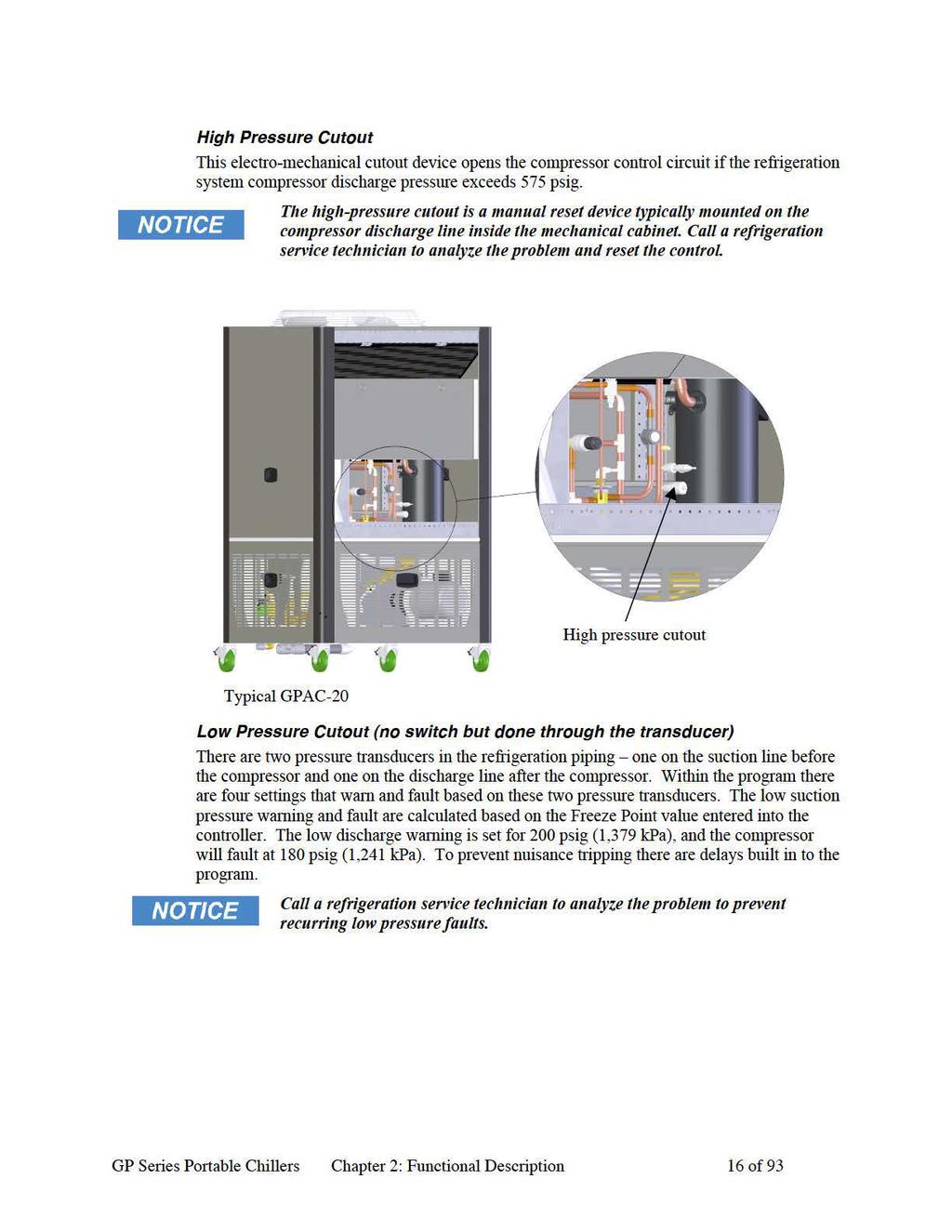
16
17 Flow Switch The thermal dispersion flow switch cutout device, mounted in the process piping, shuts down the chiller if it senses that the water/glycol flow rate through the evaporator has dropped below an acceptable level. The flow switch opens the control circuit and shuts down the pump and the chiller. Remote Start/Stop Interlock An additional contact is provided to allow the remote starting or stopping of the chiller. To use this feature install a switch or dry contact interlock connected in series between terminals 4 and 23. Refer to the electrical schematic supplied in the control enclosure. Once the wiring is complete the controller will need to be reconfigured in the supervisor settings. 2-5 Optional Features Options marked with * indicate options that can be factory installed or retrofitted in the field. Automatic Water Make-Up*. Not available on chillers less reservoir tank. This option includes an electric water solenoid valve, and the necessary internal piping to connect the chiller to a make-up water source. The controller uses the standard tank level pressure transducer to determine when to fill the tank. See Appendi for typical piping diagrams. Customer piping must provide backflow protection and venting of tank to atmosphere to prevent over-pressurization of the reservoir tank (not needed for open tank). See Section 7-7 for flow schematics. Process Water Side-stream Filter*. Not available on chillers less pump and reservoir tank. This option includes a 50 micron filter, flow indicator, ball valve for throttling water flow, and the necessary piping to provide constant filtering of the process water at about one gallon per minute (1 gpm/3.8lpm). General Fault Indicator Audible/Visual Alarm*. This option includes a 100 db audible alarm horn/ visual alarm strobe and silence button with provisions for customer wiring indication interlock. The alarm signals anytime that a fault is recognized during the operation of the chiller. Communications Options*. This option provides the capability for the unit s controller to communicate with an eternal device using a variety of serial communication protocols. Currently the unit can communicate over RS-485 Modbus RTU, BACNet, LONWorks, Ethernet Modbus. High Pressure Fans. Provides either 0.3 WC (75 Pa) or 1.0 WC (250 Pa) of eternal static pressure on fan discharge. High-pressure fans are necessary and must be included in chiller installations where eiting air ehausts through ductwork. The 0.3 WC (75 Pa) static fan can be retrofitted without sheet metal modification, but will require changing out fan housing, fan blades, fan motors and electrical components. Variable Speed Fan GPAC Reduces the speed of the fan based on refrigerant pressure and system load, allowing the chiller to operate in ambient temperatures below 75ºF (24ºC). This option will also reduce fan noise in lower ambient temperatures and low loads. GP Series Portable Chillers Chapter 2: Functional Description 17 of 93
18
19

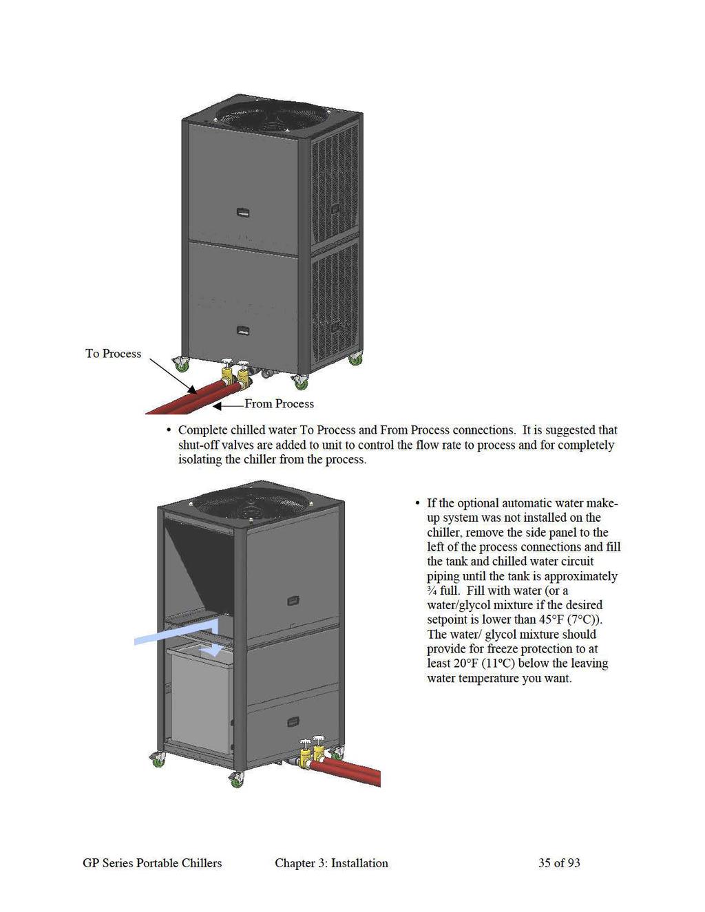
20 3-3 Process Water Connections All of our portable chillers have two chilled water connections. The chilled water supply, labeled To Process is the outlet for the chilled water leading to the process being cooled. The chilled water return, labeled From Process is the inlet leading from the process back into the chiller to be cooled and re-circulated. Figure 2: Typical GP20-50 Air Cooled Process Piping Connections All eternal chilled water connections should be run full size to the process. Flow and pressure information is available in the Appendi. The largest possible openings and passages should be provided for the flow of chilled water through platens, dies, molds, or other pieces of equipment. Flow control valves are not supplied, but should be added to the system to adjust flow and pressure to the process and to isolate the chiller from the process if necessary. Be sure to reduce eternal pressure drop as much as possible by generously sizing piping and tooling water passageways. 3-4 Bypass Valve Considerations Our portable chillers have an internal manual bypass valve. If the flow is stopped to the process while the chiller is running, the factory-set bypass valve allows a small amount of water to flow through the chiller. This action allows the chiller to keep functioning while the flow is stopped to process. The bypass valve is not intended to provide continuous full bypass flow.! Do not attempt to adjust or otherwise tamper with the internal bypass. Your warranty will be voided. GP Series Portable Chillers Chapter 3: Installation 20 of 93
21 3-5 Galvanic Corrosion Considerations The materials used in the water circuit piping of these chillers are non-ferrous and react electro-chemically with ferrous metallic materials. Some water has dissolved minerals that greatly accelerate the reaction between dissimilar metals. PVC or non-ferrous piping is recommended to reduce galvanic action. If iron piping must be used, use dielectric unions at the chiller, and water treatment is required. The use of galvanized piping is discouraged because the rough inside surface promotes debris to stick and eventually block the flow of the process fluid Water Treatment Considerations Water treatment is an integral part of the system. In some locations, water may cause large deposits of scale, erosion, algae, and/or corrosion. The use of poor quality water may result in inefficient operation, heat echanger damage, and pump seal damage. Consult a qualified water treatment specialist to determine what type of treatment is needed. 3-7 Condenser Considerations Water-Cooled Chiller Condensers Water-cooled portable chillers can use city water or tower water as a cooling medium. Make sure that all eternal piping and connections supplying and discharging water to and from the condenser are full size. You will make two connections to the water-cooled condenser: Condenser Water In. The condenser water supply is labeled Condenser Water In. It is the inlet for city or tower water. For the GPWC20-50, this connection is located near the bottom of the chiller. For all other sizes this connection is located near the top of the chiller. Make sure that water is supplied at a maimum temperature of 85ºF (29ºC) and a minimum pressure of 25 psi.! The electronic water-regulating valves pressure setpoint is set at the factory. Only a qualified refrigeration technician should adjust the pressure setting. Please contact our service group at to schedule an appointment. Normal HFC-410a refrigerant condensing pressure is 342 psi (2,360 kpa), with 85ºF (27ºC) water at 25 psi entering condenser water pressure Condenser Water Out. Condenser water return is labeled Condenser Water Out. It is the outlet for water after it has passed through the condenser. For the GPWC20-50, this connection is located near the bottom of the chiller. For all other sizes this connection is located near the top of the chiller. It is connected to the tower water return line or to a sewer or other approved discharge receiver. A water-regulating valve is a standard feature in the condenser water out line. GP Series Portable Chillers Chapter 3: Installation 21 of 93

22 Figure 3: Typical GP20-50 Water Cooled Condenser Connections Air-Cooled Chiller Condensers Air-cooled chillers use the surrounding air to cool the condenser. Install the chiller in an area where there is free passage of air for condensing and provisions for removal of heated air from the area. Do not locate air-cooled chillers in locations where steam, hot air, or fume ehausts can be drawn into the chiller.! Clean air-cooled condensers and filters frequently. Failure to do so results in reduced capacity, increased operating costs, and possible failure of the equipment. Cleaning instructions can be found in the Maintenance chapter of this manual Normal maimum refrigerant condensing pressure with 95ºF (35ºC) air entering the condenser is 420 psi (2896 kpa). Condensing Air Temperature. Our air-cooled portable chillers are designed to operate at a minimum condenser entering air temperature of approimately 75ºF (24ºC). Operation of the equipment at a lower condenser entering air temperature can cause the chiller to malfunction. For entering air temperatures below 75ºF (24 C), an optional fan motor speed control is available. We recommend maintaining a minimum 75ºF (24 C) ambient temperature. For all chillers manufactured with Variable Frequency Drives the voltage may vary up to 10% from the converter nominal voltage. However, the phase-to-phase input voltage imbalance must not eceed 3%. If the input voltage does have an imbalance from phase to phase greater than 3% then a line reactor must be installed to prevent faults within the VFD. For remote condenser units, the maimum recommended motor cable length between the VFD and the motor without output chokes is 30 m (100 ft). With output chokes the motor cable length may be etended to 65 m (195 ft). GP Series Portable Chillers Chapter 3: Installation 22 of 93
23 Remote Air-Cooled Chiller Condensers Remote air-cooled portable chillers are shipped with nitrogen holding charge and a full charge of oil (ecluding the amount needed for field piping). The remote air condenser is shipped with a dry nitrogen charge. Verify that the holding charge has not been lost prior to installation. If there is no pressure, leak test the unit and repair before installing the interconnecting refrigerant piping. Read this entire section before installation. Piping should be hard/drawn type L or type K refrigerant grade copper tubing only. Proper sizing and installation has a significant effect on system performance, reliability, and safety. The copper tubing and fittings used must have a minimum burst pressure of 1,950 psi. Interconnecting Refrigerant Piping. The chiller and condenser refrigerant lines are terminated with a cap and brazed closed. Use a tube cutter to remove caps. Do not use a saw to remove the end caps because this will allow copper chips to contaminate the system. A certified refrigeration contractor needs only to install the interconnecting refrigerant piping between the chiller and the outdoor air-cooled condenser. This piping must be properly sized, type L or type K refrigerant grade tubing, high temperature brazed. Install a customer supplied 650 psi approved refrigerant relief valve in the discharge line at the condenser, following all applicable codes. Flow dry nitrogen through the system when brazing copper joints to prevent carbon/scale formation; which causes contamination. Isolate the refrigerant lines from the building, preventing transfer of line vibration to the structure. Do not secure the lines rigidly. Leak check and evacuate the system down to 400 microns. A decay of 50 microns after one hour is acceptable. To prevent injury or death due to eplosion and/or inhalation of hydrogenfluoride gas, purge system thoroughly while brazing refrigerant piping connections. Use a pressure regulator in the line between the unit and the high-pressure nitrogen cylinder to avoid over-pressurization and possible eplosion. System Configuration. The system can be configured in any of the arrangements shown on page 78 of the Appendi. The configuration and distance between the chiller and the condenser affects pipe size, refrigerant charge, oil return, and oil charge. Therefore there are limitations that must be adhered to for reliable and optimal operation. Leaving water temperature affects discharge line size. Be sure to inform the installing contractor of the leaving water temperature range in which the chiller will be operating The total distance between the chiller and condenser must not eceed 200 feet or 300 equivalent pipe feet Discharge line risers cannot eceed an elevation difference greater than 100 feet without a 2% efficiency decrease. Refer to page 78 of the Appendi for the location of traps. GP Series Portable Chillers Chapter 3: Installation 23 of 93
24 Refrigeration lines must not be crossed, i.e., chiller liquid lines are to be piped to condenser liquid lines. Sizing Refrigerant Lines. To determine field installed liquid and discharge line sizes, first establish the equivalent length of pipe for each line, valve, and elbow. Chiller capacity and leaving water temperature range is also required. See Figure 4 on page 24 for lengths of refrigerant valves and fittings. Liquid Line Sizing. The liquid line should be sized as small as possible while maintaining acceptable pressure drop to minimize the refrigerant charge. Liquid line risers must not eceed 15 feet from the base of the air-cooled condenser. Horizontal runs do not require a pitch. Insulation is not required unless the line is installed in a high ambient area, i.e., boiler room or on a roof. Install a liquid line-charging valve to facilitate refrigerant charging. See Figure 5 on page 24 for sizing information. See Figure 7 on page 28 for charge determination. Discharge Line Sizing. Discharge line sizing is based on the velocity required for sufficient oil return back to the compressor. See Figure 4: Equivalent Length in Feet for Valves and Fittings on page 27 for discharge line sizing. For horizontal runs, the discharge line should be pitched downward, in the direction of flow, at a rate of 1/2 for every 10 feet. This will allow oil to flow towards the condenser. Figure 4: Equivalent Length in Feet for Valves and Fittings Line Size OD (inches) Angle Valve Short Radius EL Long Radius EL 3/ / / / / / / / / / Figure 5: Liquid Line Sizing GPRC-20 Total Equiv. Length (Ft) Horizontal or Downflow Liquid Line Size (OD") Upflow 1-5 Ft Upflow 6-10 Ft Upflow Ft GPRC-30 Total Equiv. Length (Ft) Horizontal or Downflow Liquid Line Size (OD") Upflow 1-5 Ft Upflow 6-10 Ft 25 1/2 1/2 1/2 1/2 25 5/8 5/8 5/8 5/8 50 1/2 1/2 1/2 1/2 50 5/8 5/8 5/8 5/8 75 1/2 1/2 1/2 1/2 75 5/8 5/8 5/8 5/ /2 1/2 1/2 5/ /8 5/8 5/8 5/ /2 1/2 1/2 5/ /8 5/8 5/8 5/ /2 1/2 5/8 5/ /8 5/8 5/8 5/ /2 5/8 5/8 5/ /8 5/8 5/8 3/ /2 5/8 5/8 5/ /8 5/8 5/8 3/ /2 5/8 5/8 5/ /8 5/8 5/8 3/ /8 5/8 5/8 5/ /8 5/8 3/4 3/ /8 5/8 5/8 5/ /8 5/8 3/4 3/ /8 5/8 5/8 5/ /8 5/8 3/4 3/4 Upflow Ft GP Series Portable Chillers Chapter 3: Installation 24 of 93
25 GPRC-40 Liquid Line Size (OD") GPRC-50 Liquid Line Size (OD") Horizontal Horizontal Total Equiv. or Upflow Upflow Upflow Total Equiv. or Upflow Upflow Upflow Length (Ft) Downflow 1-5 Ft 6-10 Ft Ft Length (Ft) Downflow 1-5 Ft 6-10 Ft Ft 25 5/8 5/8 5/8 3/4 25 7/8 7/8 7/8 7/8 50 5/8 5/8 3/4 3/4 50 7/8 7/8 7/8 7/8 75 5/8 5/8 3/4 3/4 75 7/8 7/8 7/8 7/ /8 3/4 3/4 3/ /8 7/8 7/8 7/ /4 3/4 3/4 7/ /8 7/8 7/8 7/ /4 3/4 3/4 7/ /8 7/8 7/8 7/ /4 3/4 3/4 7/ /8 7/8 7/8 7/ /4 3/4 3/4 7/ /8 7/8 7/8 7/ /4 3/4 7/8 7/ /8 7/8 7/8 7/ /4 3/4 7/8 7/ /8 7/8 7/8 7/ /4 3/4 7/8 7/ /8 7/8 7/8 1-1/ /4 3/4 7/8 7/ /8 7/8 7/8 1-1/8 GPRC-70 Liquid Line Size (OD") GPRC-90 Liquid Line Size (OD") Total Equiv. Length (Ft) Horizontal or Downflow Upflow 1-5 Ft Upflow 6-10 Ft Upflow Ft Total Equiv. Length (Ft) Horizontal or Downflow Upflow 1-5 Ft Upflow 6-10 Ft Upflow Ft 25 7/8 7/8 7/8 7/ /8 1-1/8 1-1/8 1-1/8 50 7/8 7/8 7/8 7/ /8 1-1/8 1-1/8 1-1/8 75 7/8 7/8 7/8 7/ /8 1-1/8 1-1/8 1-1/ /8 7/8 7/8 7/ /8 1-1/8 1-1/8 1-1/ /8 7/8 7/8 7/ /8 1-1/8 1-1/8 1-1/ /8 7/8 7/8 1-1/ /8 1-1/8 1-1/8 1-1/ /8 7/8 7/8 1-1/ /8 1-1/8 1-1/8 1-1/ /8 7/8 1-1/8 1-1/ /8 1-1/8 1-1/8 1-1/ /8 7/8 1-1/8 1-1/ /8 1-1/8 1-1/8 1-1/ /8 7/8 1-1/8 1-1/ /8 1-1/8 1-1/8 1-1/ /8 1-1/8 1-1/8 1-1/ /8 1-1/8 1-1/8 1-1/ /8 1-1/8 1-1/8 1-1/ /8 1-1/8 1-1/8 1-1/8 GP Series Portable Chillers Chapter 3: Installation 25 of 93
26 GPRC-105 Liquid Line Size (OD") GPRC-140 Liquid Line Size (OD") Total Equiv. Length (Ft) Horizontal or Downflow Upflow 1-5 Ft Upflow 6-10 Ft Upflow Ft Total Equiv. Length (Ft) Horizontal or Downflow Upflow 1-5 Ft Upflow 6-10 Ft Upflow Ft /8 1-1/8 1-1/8 1-1/ /8 1-1/8 1-1/8 1-1/ /8 1-1/8 1-1/8 1-1/ /8 1-1/8 1-1/8 1-1/ /8 1-1/8 1-1/8 1-1/ /8 1-1/8 1-1/8 1-1/ /8 1-1/8 1-1/8 1-1/ /8 1-1/8 1-1/8 1-1/ /8 1-1/8 1-1/8 1-1/ /8 1-1/8 1-1/8 1-1/ /8 1-1/8 1-1/8 1-1/ /8 1-1/8 1-1/8 1-1/ /8 1-1/8 1-1/8 1-1/ /8 1-1/8 1-1/8 1-3/ /8 1-1/8 1-1/8 1-1/ /8 1-1/8 1-1/8 1-3/ /8 1-1/8 1-1/8 1-1/ /8 1-1/8 1-1/8 1-3/ /8 1-1/8 1-1/8 1-1/ /8 1-1/8 1-3/8 1-3/ /8 1-1/8 1-1/8 1-1/ /8 1-1/8 1-3/8 1-3/ /8 1-1/8 1-1/8 1-3/ /8 1-1/8 1-3/8 1-3/8 GPRC-175 Liquid Line Size (OD") GPRC-210 Liquid Line Size (OD") Total Equiv. Length (Ft) Horizontal or Downflow Upflow 1-5 Ft Upflow 6-10 Ft Upflow Ft Total Equiv. Length (Ft) Horizontal or Downflow Upflow 1-5 Ft Upflow 6-10 Ft Upflow Ft /8 1-3/8 1-3/8 1-3/ /8 1-3/8 1-3/8 1-3/ /8 1-3/8 1-3/8 1-3/ /8 1-3/8 1-3/8 1-3/ /8 1-3/8 1-3/8 1-3/ /8 1-3/8 1-3/8 1-3/ /8 1-3/8 1-3/8 1-3/ /8 1-3/8 1-3/8 1-3/ /8 1-3/8 1-3/8 1-3/ /8 1-3/8 1-3/8 1-3/ /8 1-3/8 1-3/8 1-3/ /8 1-3/8 1-3/8 1-3/ /8 1-3/8 1-3/8 1-3/ /8 1-3/8 1-3/8 1-3/ /8 1-3/8 1-3/8 1-3/ /8 1-3/8 1-3/8 1-5/ /8 1-3/8 1-3/8 1-3/ /8 1-3/8 1-3/8 1-5/ /8 1-3/8 1-3/8 1-3/ /8 1-3/8 1-3/8 1-5/ /8 1-3/8 1-3/8 1-3/ /8 1-3/8 1-5/8 1-5/ /8 1-3/8 1-3/8 1-3/ /8 1-3/8 1-5/8 1-5/8 GP Series Portable Chillers Chapter 3: Installation 26 of 93
27 Figure 6: Discharge Line Sizing Horizontal or Downflow Discharge Line Sizes (OD") Total Equivalent Length (Ft) Model GPRC-20 5/8 5/8 5/8 5/8 3/4 3/4 3/4 3/4 3/4 3/4 3/4 7/8 GPRC-30 7/8 7/8 7/8 7/8 7/8 7/8 7/8 7/8 7/8 7/8 7/8 7/8 GPRC-40 7/8 7/8 7/8 7/8 7/8 7/8 7/8 1-1/8 1-1/8 1-1/8 1-1/8 1-1/8 GPRC-50 7/8 7/8 1-1/8 1-1/8 1-1/8 1-1/8 1-1/8 1-1/8 1-1/8 1-1/8 1-3/8 1-3/8 GPRC-70 7/8 1-1/8 1-1/8 1-3/8 1-3/8 1-3/8 1-3/8 1-3/8 1-3/8 1-3/8 1-5/8 1-5/8 GPRC /8 1-1/8 1-1/8 1-1/8 1-3/8 1-3/8 1-3/8 1-3/8 1-3/8 1-3/8 1-5/8 1-5/8 GPRC /8 1-1/8 1-1/8 1-3/8 1-3/8 1-3/8 1-3/8 1-3/8 1-3/8 1-5/8 1-5/8 1-5/8 GPRC /8 1-3/8 1-3/8 1-3/8 1-5/8 1-5/8 1-5/8 1-5/8 1-5/8 1-5/8 1-5/8 2-1/8 GPRC /8 1-3/8 1-3/8 1-5/8 1-5/8 1-5/8 1-5/8 1-5/8 2-1/8 2-1/8 2-1/8 2-1/8 GPRC /8 1-5/8 1-5/8 1-5/8 1-5/8 1-5/8 2-1/8 2-1/8 2-1/8 2-1/8 2-1/8 2-1/8 Circuit Tons GPRC-20 GPRC-30 GPRC-40 GPRC-50 GPRC-70 GPRC-90 GPRC-105 GPRC-140 GPRC-175 GPRC-210 Upflow Discharge Line Sizes (OD") Total Equivalent Length (Ft) /8 5/8 5/8 5/8 A-3/8 A-3/8 A-3/8 A-3/8 A-3/8 A-3/8 A-3/8 A-3/8 B-5/8 B-5/8 B-5/8 B-5/8 B-5/8 B-5/8 B-5/8 B-3/4 A-3/8 A-3/8 A-3/8 A-3/8 A-3/8 A-3/8 A-3/8 A-3/8 A-3/8 A-3/8 A-3/8 A-3/8 B-3/4 B-3/4 B-3/4 B-3/4 B-3/4 B-3/4 B-3/4 B-3/4 B-3/4 B-3/4 B-3/4 B-3/4 A-3/8 A-3/8 A-3/8 A-3/8 A-3/8 A-3/8 A-3/8 A-1/2 A-1/2 A-1/2 A-1/2 A-1/2 B-3/4 B-3/4 B-3/4 B-3/4 B-3/4 B-3/4 B-3/4 B-7/8 B-7/8 B-7/8 B-7/8 B-7/8 7/8 7/8 A-1/2 A-1/2 A-1/2 A-1/2 A-1/2 A-1/2 A-1/2 A-1/2 A-1/2 A-1/2 B-7/8 B-7/8 B-7/8 B-7/8 B-7/8 B-7/8 B-7/8 B-7/8 B-1-1/8 B-1-1/8 7/8 7/8 A-1/2 A-1/2 A-1/2 A-1/2 A-1/2 A-1/2 A-1/2 A-1/2 A-5/8 A-5/8 B-7/8 B-7/8 B-1-1/8 B-1-1/8 B-1-1/8 B-1-1/8 B-1-1/8 B-1-1/8 B-1-3/8 B-1-3/8 1-1/8 1-1/8 1-1/8 1-1/8 A-3/4 A-3/4 A-3/4 A-3/4 A-3/4 A-3/4 A-3/4 A-3/4 B-1-1/8 B-1-1/8 B-1-1/8 B-1-1/8 B-1-1/8 B-1-1/8 B-1-1/8 B-1-1/8 1-1/8 1-1/8 1-1/8 A-3/4 A-3/4 A-3/4 A-3/4 A-3/4 A-3/4 A-3/4 A-3/4 A-3/4 B-1-1/8 B-1-1/8 B-1-1/8 B-1-1/8 B-1-1/8 B-1-1/8 B-1-3/8 B-1-3/8 B-1-3/8 1-1/8 1-3/8 1-3/8 1-3/8 A-3/4 A-3/4 A-3/4 A-3/4 A-3/4 A-3/4 A-3/4 A-3/4 B-1-3/8 B-1-3/8 B-1-3/8 B-1-3/8 B-1-3/8 B-1-3/8 B-1-3/8 B-1-3/8 1-3/8 1-3/8 1-3/8 A-3/4 A-3/4 A-3/4 A-3/4 A-3/4 A-3/4 A-3/4 A-3/4 A-3/4 B-1-3/8 B-1-3/8 B-1-3/8 B-1-3/8 B-1-3/8 B-1-3/8 B-1-3/8 B-1-3/8 B-1-3/8 1-5/8 1-5/8 1-5/8 1-5/8 1-5/8 1-5/8 A-3/4 A-3/4 A-3/4 A-3/4 A-3/4 A-3/4 B-1-5/8 B-1-5/8 B-1-5/8 B-1-5/8 B-1-5/8 B-1-5/8 GP Series Portable Chillers Chapter 3: Installation 27 of 93
28 Refrigerant Charge Determination. The approimate amount of refrigerant charge required by the system varies based on the total length of the refrigerant lines and the size of the chiller. Referring to Figure 7, determine the amount of charge based on the model of the chiller and the amount of charge based on discharge and liquid line sizes and lengths. Add these three numbers together to find the final operating charge. The final operating charge must be verified by running the system and checking the liquid line sight glass. Figure 7: Refrigerant Charge Determination Chiller Model Condenser and Chiller Charge (LBS of R-410a) Minimum Design Ambient - F GPRC GPRC GPRC GPRC GPRC GPRC GPRC GPRC GPRC GPRC Line Size OD (inches) Discharge Line LBS of R-410a 3/ / / / / / Liquid Line LBS of R-410a 1-3/ / / / The amounts listed above are based on 100 feet of pipe. Actual amounts will be in direct proportion to the actual length of the piping. Oil Charge Determination. The remote air-cooled portable chillers are factory charged with the amount of oil required without field-installed piping. Additional oil required is dependent on the amount of additional refrigerant added. Calculate the amount of additional oil required by using the following formula: Pints of oil (Copeland Ultra 22cc) = lbs of R-410a added for field installed piping / 100. GP Series Portable Chillers Chapter 3: Installation 28 of 93
29 GP Series Portable Chillers Chapter 3: Installation 29 of 93
30 Figure 8: Remote Condenser Configurations Figure 9: Double Riser Detail 3-8 Checking Motor Direction All of our portable chillers have their motor rotations properly phased at the factory. If compressors, pumps, or fans are running in reverse rotation, disconnect and lock out the power source and reverse any two power leads into the chiller disconnect switch. Do not switch leads at the motors, motor starters, or contactors. Three-Phase Compressors Scroll compressors are directionally-dependent and compress in one rotational direction. Reversing rotation direction results in an elevated sound level and a substantially-reduced current draw. Do not allow the compressor to run backwards for any length of time. Doing so will result in compressor damage.. Water Pumps Correct pump rotation is indicated by a positive pressure of 20 to 40 psi shown on the home screen of the display. Pump rotation should be clockwise when viewed from the motor end. For chillers with optional pumps, check the appropriate pump curve in the Appendi. Do not run pump dry. Doing so will result in seal damage. Condenser Fan Air should be drawn through the condenser and discharged vertically from the chiller. GP Series Portable Chillers Chapter 3: Installation 30 of 93
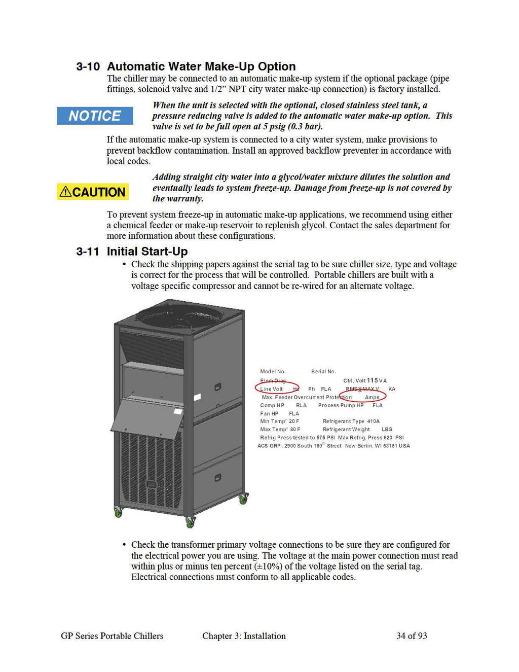
31
32
33
34
35
36
37 3-12 Finishing Setup: Setting Up Passwords You can establish passwords for two levels of security: operators and supervisors. The controller comes from the factory with neither password set. This allows every user access to all functions. If you choose to establish passwords store them in a secure location because if they are forgotten there is no way to reset them without a service call. Operator Password. If you define a password for operators, then a password will be required to carry out any function (other than reviewing the status screens). Entering the operator s password will give the user access to the setpoints for leaving temperature, high temperature warning, high temperature fault. If you choose to define an Operator Password you must also define a Supervisor Password to complete the security setup. Supervisor Password. If you define a password for supervisors (or setup personnel) then most settings can be changed only after entering the password. The password will be required to display the etended setpoints for operating parameters and alarms. Section 4-6 shows a table of setpoints and the restrictions between Operator and Supervisor. GP Series Portable Chillers Chapter 3: Installation 37 of 93

38 To set password protections: 1. Press the button to access the menu screen. 2. Press the or to highlight SETPOINTS, and press. 3. Press the or until the following screen appears for the Operator or Supervisor Password 4. Press to accept the screen, and then press until the Operator or Supervisor Password line is highlighted. 5. Press or to increment or decrement the number. The password can be between 0 and Press to accept the Password and move to the net line. 7. For either Operator or Supervisor password the time that the password will allow the controller to be active can be set by the Operator or Supervisor Password Time. With the PW Time value highlighted, press or to increment or decrement the time. The password time for either setup can be from 0 to 99 minutes. GP Series Portable Chillers Chapter 3: Installation 38 of 93

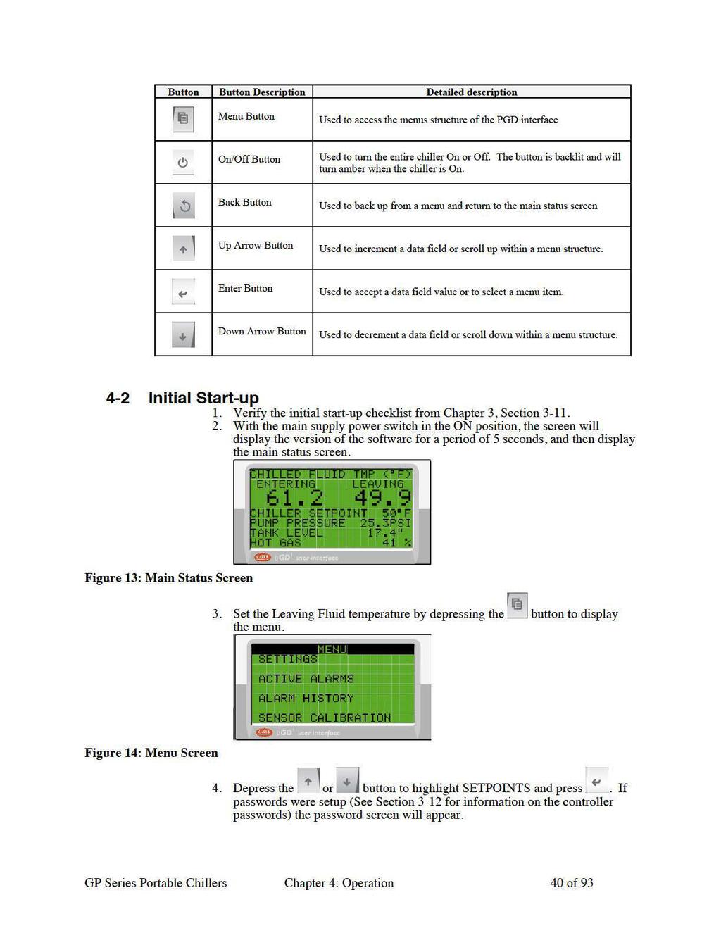
39 Chapter 4: Operation 4-1 Panel Buttons, Indicator Lights, and Switches Microprocessor Controller The standard chillers use a microprocessor-based PID controller. The Carel PCO controller is located in the control enclosure. The Carel PGD1 Interface is housed in a block of rigid plastic with a magnetic backing that allows the user to stick the interface on any metallic surface. The GP20 through GP50 units come standard with a 10 ft (3 m) cable, and the GP70 through GP210 units come standard with a 20 ft (6 m) cable. Longer cables are available through the After Market Sales Group. The controller is factory set and adjusted; no field adjustment to the internal controls is necessary. The standard operation range is 20ºF to 80ºF (-7ºC to 27ºC). Operating the chiller setpoint below 45 F (7 C) without the proper amount of glycol for freeze protection could result in a damaged evaporator. ACS Group does not warrant the freeze up of the evaporator under any circumstances. Figure 12: Controller Display GP Series Portable Chillers Chapter 4: Operation 39 of 93
40
41 Enter the established Operator Password by depressing the to move the position of the cursor, and then depressing the or button to increment or decrement the number. Once all of the numbers have been entered depress the appear. to accept the password. The following screen will Figure 15: Operator Setpoints Screen 5. Depress to move the cursor to the CHILLED FLUID SP line. Use the or button to increment or decrement the value. Depress to accept the value and move the cursor down one line. 6. Depress the button twice to return to the main status screen. 7. Depress the to start the chiller. 8. Check pump rotation 9. Check the pump amp draw and pump pressure. Make sure that the amp draw reading is within the running load and service factor amps. 10. Operate the chiller, looking for any leaks and listening for unusual noises or vibrations that could indicate improper operation. Elevated sound level and substantially reduced current draw indicate reverse rotation. After several minutes of operation, the compressor internal protector trips. GP Series Portable Chillers Chapter 4: Operation 41 of 93
42 4-3 Status Screens The controller has eight (8) preconfigured status screens. The main status screen (shown in Figure Figure 16) shows the main operating points of the chiller: Entering and Leaving fluid temperatures; Leaving fluid setpoint, pump discharge pressure, tank fluid level (depth), and percentage of hot-gas bypass output. Figure 16: Main Chiller Status Screen Depressing cycles through the following screens (shown below) Analog I/O, Digital I/O, and Test. The Analog and Digital I/O screens provide status of all of the inputs and outputs for the controller. The Test aides in troubleshooting the chiller when it is not functioning properly by displaying the basic information that a service person will need to know to determine the problem. GP Series Portable Chillers Chapter 4: Operation 42 of 93

43 GP Series Portable Chillers Chapter 4: Operation 43 of 93
44 The chiller can be equipped with a tempered fluid loop inside of the chiller. If this option is installed, the main screen changes to the following. GP Series Portable Chillers Chapter 4: Operation 44 of 93
45 4-4 Access Levels The controller is setup to allow access to three distinct password groups: operator, supervisor, and service. Operator access allows the user to modify the Leaving Water Temp, Hi Temp Warning, and Hi Temp Fault setpoints. Supervisor access allows the supervisor to modify the above plus Selecting any of the menus in the Menu Screen will display the Password Screen. 4-5 Controller Setpoints Variable Description Access Level Operator Supervisor Chilled Fluid SP Temperature of chilled fluid out to process Chil Hi Temp Wrn Chil Hi Temp Flt Setpoint for alarm to warn when chilled leaving fluid temperature is too high Setpoint to shut down pump and compressor based on leaving fluid temperature Process SP Temperature of tempered fluid out to process Proc Hi Temp Wrn Proc Hi Temp Flt Proc Low Temp Wrn Proc Low Temp Flt Setpoint for alarm to warn when tempered leaving fluid temperature is too high Setpoint for alarm to warn when tempered leaving fluid temperature is too high Setpoint for alarm to warn when tempered leaving fluid temperature is too low Setpoint for alarm to warn when tempered leaving fluid temperature is too low Cooling Enabled Refrigeration system allowed to operate Heating Enabled Fluid Freeze Point Chill On Diff Chill Off Diff Proc On Diff Proc Off Diff Proc Hi Temp Dly Optional Process temperature heater allowed to operate Lowest temperature fluid will operate without freezing. Below 32 F (0 C) glycol must be added. Forces lowest Chilled fluid setpoint to be 13 F (7 C) above FFP Temperature difference above chilled fluid setpoint before compressor turns on Temperature difference below chilled fluid setpoint before compressor turns off Temperature difference below process setpoint before process heater turns on Temperature difference above process setpoint before process heater turns off Time (in seconds) Process High Temperature alarm is ignored before activating GP Series Portable Chillers Chapter 4: Operation 45 of 93
46 Variable Chil Hi Temp Dly Hi Temp Flt Type Chil Lo T Wrn Dif Chil Lo T Flt Dif Comp, Lead Cmp On Delay Comp, Lead Cmp Off Delay Lag Cmp On Dly Lag Cmp Off Dly Description Time (in seconds) Chilled High Temperature alarm is ignored before activating When set to CRIT, chiller and process high temp alarms will deactivate compressors and pumps. When set to WARN, compressors and pumps are allowed to continue to operate when a high temp alarm occurs Temperature difference below the chiller setpoint before the chiller low temp warning alarm occurs Temperature difference below the chiller setpoint before the chiller low temp fault alarm occurs. Temperature Difference between Leaving Fluid Temperature and Setpoint to turn on the compressor Temperature Difference between Leaving Fluid Temperature and Setpoint to turn off the compressor Time (in minutes) before lag compressor is energized once Chilled fluid reaches 2 F (1.1 C) above Chilled Fluid setpoint Time (in minutes) before lag compressor is deenergized once chilled fluid reaches 2 F (1.1 C) below Chilled Fluid setpoint Access Level Operator Supervisor Cond Fan Start Discharge pressure which energizes condenser fan Cond Fan Stop Pump Stop Delay Heater On Delay Heater Cycle Tm Discharge pressure which de-energizes condenser fan Delay time in seconds between fault and stopping the pump Time (in seconds) before the heater is allowed to activate once the last compressor stages off Time (in seconds) between sampling the output of the heater s PID loop. For eample, if this variable is set to ten (10), the heater PID loop output is checked every ten seconds. If the heater PID loop output is 70% when sampled the heater output will be on for 7 seconds and off for 3 seconds. Heater P P parameter of the heater PID loop Heater I I parameter of the heater PID loop Heater D D parameter of the heater PID loop Cooling Valve P P parameter of the cooling valve PID loop Cooling Valve I I parameter of the cooling valve PID loop Cooling Valve D D parameter of the cooling valve PID loop Cooling Valve Mode Cooling Valve Pos Tank Min Lvl When in AUTO, the cooling valve is controlled by the cooling valve PID loop. When in MANUAL, the cooling valve is forced open to the percent dictated by the Cooling Valve Pos variable. When the Cooling Valve Mode is set to MANUAL, this variable dictates what percentage the valve is forced to. Minimum tank level. Used to set the default low tank lefvel alarm setpoints as well as the auto-water makeup on setpoint. GP Series Portable Chillers Chapter 4: Operation 46 of 93

47 Variable Tank Ma Lvl Low Level Fault Low Level Warning Wtr Makeup On Wtr Makeup Off High Lvl Warning High Lvl Fault Description Maimum tank level. Used to set the default high tank level alarm setpoints as well as the auto-water makeup off setpoint. Tank level that will activate Low Level Warning fault Tank level that will activate Low Level Warning alarm The tank level to turn on optional water make-up valve; based on size of tank The tank level to turn off optional water make-up valve; based on size of tank. Tank level that will activate High Level Warning alarm Tank level that will activate High Level Warning fault Access Level Operator Supervisor Mkup Min Rt X.X /XXS The minimum allowable rate for filling the tank Operator Password 4 digit password to limit operator interaction Operator Pw Time Time in minutes for operator password to be active Sprvisor Password 4 digit password for supervisory interaction Sprvisor Pw Time Time in minutes for supervisor password to be active Alarm Silence Time Set Clock Reset to Defaults Time in minutes to silence alarm (with optional audible alarm). After time alarm will reactivate. Allows for the time to be set if the clock card option is installed Resets all parameters to the default parameters, including configuration 1. Set the Leaving Fluid temperature by depressing the button to display the menu. Figure 17: Menu Screen 2. Depress the or button to highlight SETTINGS and press. If passwords were setup (See Section 3-12 for information on the controller passwords) the password screen will appear. GP Series Portable Chillers Chapter 4: Operation 47 of 93
48 Enter the Operator Password by depressing the to move the position of the cursor, and then depressing the or button to increment or decrement the number. Once all of the numbers have been entered depress the to accept the password. The following screen will appear. Figure 18: Operator Setpoints Screen 3. Depress to move the cursor to the Leaving Temp line. Use the or button to increment or decrement the value. Depress to accept the value and move the cursor down one line. 4. Adjust the Hi Temp Warning and Hi Temp Fault in the same manner. 5. Depress the button twice to return to the main status screen. GP Series Portable Chillers Chapter 4: Operation 48 of 93
49 4-6 Configuration Settings Within the Supervisor Menu the chiller can be configured if options are added in the field. These configurations are described below. Variable Description Access Level Operator Supervisor Tank Level Inst Activates/Deactivates the tank level control sensor Auto Water Make-up Fan Control Disch Press Cntl Sensor Pack Inst Cond Diff Sw Inst Chill Diff Sw Inst Activates the automatic water makeup valve within the controller Set to CYCLING when a standard fan starter is used to control the fan. Set to VFD when a variable frequency drive is used to control the fan When set to SP, the chiller will control to a static SP. When set to AUTO, the chiller will adjust the discharge pressure setpoint based on the current conditions to increase efficiency. Activates the optional temperature sensors for refrigerant liquid line and suction line temperatures, and entering air or water temperature (depending on condenser type) Activates the optional water cooled condenser differential water pressure switch Activates the optional evaporator differential water pressure switch Clock Board Inst Activates the optional controller real time clock card Heater Installed Activates the optional process heater Analog IN2 Remote SP Mode Rem SP ma Range Analog In 6 Chil Loop Type Proc Loop Type Primary Loop Analog Out 2 Determines how analog input 2 is used. It can be set to CHIL IN (chiller in temperature), FROM PROC (from process temperature), CHIL REM SP (chiller remote setpoint) or PROC REM SP (process remote setpoint). When Analog IN2 is set to REM SP, this determines if the LOCAL (entered through the display) setpoint or REMOTE (Analog IN2) setpoint is used to control the chiller. Determines the signal type (0-20mA or 2-20mA) for the Remote Setpoint Determines how analog input 6 is used. It can be set to CHIL IN (chiller in temperature), FROM PROC (from process temperature) or TO PROC (to process temperature). Determines the chiller loop s type (COOL or HEAT/COOL) Determines the process loop s type (COOL, HEAT/COOL or HEAT). Determines which loop s (PROC or CHIL) information to display on the first status page of the display. Determines how analog output 2 is used. It can be set to CHIL IN (retransmission of the chiller in temperature), CHIL OUT (retransmission of the chiller out temperature), FROM PROC (retransmission of the from process temperature), TO PROC (retransmission of the to process temperature) or COOL VLV (process loop cooling valve). GP Series Portable Chillers Chapter 4: Operation 49 of 93
50 Analog Out 3 Analog Out 4 Digital In 8 Start Mode Variable Chil Cntl Sens Proc Cntl Sens Pump 2 OL Alm Flow 2 Alm Type Alarm Out Network Prot Description Determines how analog output 3 is used. It can be set to CHIL IN (retransmission of the chiller in temperature), CHIL OUT (retransmission of the chiller out temperature), FROM PROC (retransmission of the from process temperature) or TO PROC (retransmission of the to process temperature). Determines how analog output 4 is used. It can be set to CHIL IN (retransmission of the chiller in temperature), CHIL OUT (retransmission of the chiller out temperature), FROM PROC (retransmission of the from process temperature) or TO PROC (retransmission of the to process temperature). Determines how digital input 8 is used. It can be set to START/STOP (remote start stop), NO WARNING (normally open warning alarm), NC WARNING (normally closed warning alarm), NO FAULT (normally open fault alarm), NC Fault (normally closed fault), PHASE MNTR (power phase monitor), TMP SAFETY (high temp safety) When Digital In 8 is configured to START/STOP this determines if the chiller s online status is determined by the button on the display (LOCAL) or digital input 8 (REMOTE). Determines which sensor is used to control the chiller. It can be set to CHIL OUT (chiller out temperature), CHIL IN (chiller in temperature), TO PROC (to process temperature) or FRM PROC (from process temperature). Determines which sensor is used to control the process loop. It can be set to TO PROC (to process temperature) or FRM PROC (from process temperature). When set to CRIT, the pump 2 overload alarm will deactivate compressors and pumps. When set to WARN, compressors and pumps are allowed to continue to run when the pump 2 overload alarm occurs. When set to CRIT, the flow 2 alarm will deactivate compressors and pumps. When set to WARN, compressors and pumps are allowed to continue to run when the flow 2 alarm occurs. Determines when the alarm output is activated. When set to ALL ALARMS, the output is activated when any new alarm occurs. When set to CRIT ALARMS, the output will only activate when critical alarms (those that force the pump or compressor off) occur. Determines what network protocol is used for communications. This can be set to BACNET485, BACNET IP, MODBUS485, MODBUS IP, LON or WEB. Access Level Operator Supervisor Network Baudrate Determines the baudrate for communications. Network Address Units Determines the network address of the chiller on the network. Determines if STANDARD (English) or METRIC units are used. GP Series Portable Chillers Chapter 4: Operation 50 of 93
51 4-7 Alarms The controller is setup with multiple alarms, most of them configurable using the Supervisor password. Section 4-5 Controller Setpoints on page 45 gives a list of alarms that the controller is setup to display. The alarms are broken up into two categories warnings and faults. The warning notifies the user that the parameter has been eceeded and the chiller is allowed to keep operating, but should be monitored to determine the cause of the warning. The fault notifies the user that the parameter has been eceeded and the chiller and pump has been shut down to protect the system. 4-8 Optional Communications The communications function allows you to monitor and set the parameters by a program prepared and running on a host computer connected to the controller. Serial communications use a RS-485 hardware interface. Protocols available are BACNet, LONWorks, CANBus, and ModBus RTU (Slave mode only). See Appendi for the controller data that is available through these protocols. Network communications use a RJ-45 hardware interface using the basic Ethernet TCP/IP layer stack. Protocols available are BACNet (Ethernet, IP, or MS/TP) and ModBus IP. See Appendi for the controller data that is available through these protocols. GP Series Portable Chillers Chapter 4: Operation 51 of 93
52 Chapter 5: Maintenance 5-1 Lubrication Grease all fan motors, and pump motors that do not have permanently sealed bearings. Be sure to use an all-purpose industrial grease with a temperature reference of 185 F (85 C). Remove the grease relief plug (motors only) before adding grease, add grease until a small amount pours out, and replace the plug when finished. Failure to remove the grease relief plug will result in dislodging the bearing grease seal, eventually causing bearing failure. Refrigeration compressors are hermetically sealed and no lubrication is required. 5-2 Filter Cleaning Air filter cleaning is important to keep your air-cooled portable chiller operating at peak efficiency and capacity. Clean the filters whenever they appear dirty, or at regularly scheduled intervals. 1. Turn the chiller off. 2. Remove the top side panel(s) to epose the condenser section. 3. Slide the filter rod to release it from the frame at the top and bottom. 4. Wash down the filter with clean water (preferably with a garden hose), directing the flow of water opposite the direction of airflow. If dirt is heavy, use a mild detergent and rinse well. Allow the filter to dry completely before replacing it on the chiller. Keep a spare air filter set on hand. Install and use it while cleaning). Do not use compressed air to blow off a dirty filter. It will not clean very well, and the filter could be damaged. Never run the chiller without properly installed filters. 5-3 Maintaining the Condenser Dirty condenser heat echange surfaces reduce system capacity and efficiency. Air- and Remote Air-Cooled Chillers Brush or vacuum light dirt accumulations off the aluminum condenser fins. Avoid bending or damaging them. Heavy dirt accumulations on the fins may require professional cleaning. Water-Cooled Chillers Proper water treatment will greatly reduce cleaning intervals. Coaial Condensers (GPWC20-50). Remove dirt and slime in the condenser tube water side by reverse-circulating with a mild detergent and water solution. Remove mineral deposits by reverse circulating Liquid Inhibited Acid De-Scaling Solution (Part No. A ) through the water side of the condenser. Follow the directions on the container. Shell & Tube Condensers (GPWC70-210). Remove dirt and slime in the condenser tube water side by cleaning with a nylon tube brush. Remove mineral deposits by reverse GP Series Portable Chillers Chapter 5: Maintenance 52 of 93
53 circulating Liquid Inhibited Acid De-Scaling Solution (Part No. A ) through the tube water side of the condenser. Follow the directions on the container. The refrigerant side is sealed and requires no routine maintenance. Do not use steam or water over 140ºF (60ºC) to clean a condenser unless you are monitoring the refrigeration circuit for ecessive pressure with gauges. Only a trained technician should use this method. 5-4 Maintaining the Evaporator Dirty evaporator heat echange surfaces reduce system capacity and efficiency. Remove dirt and slime in the evaporator by reverse-circulating with a mild detergent and water solution. Remove mineral deposits by reverse-circulating Non-Acid De-Scaling Solution (Part No. A ). Follow the directions on the container. 5-5 Evaporator Process Piping Y-Strainer The process piping Y-strainer requires periodic cleaning of its screen to insure the proper flow through the evaporator. To clean the strainer screen, remove the access plug and retaining cap, and pull out the screen. Wipe, brush, or vacuum out any dirt left in the strainer body. Clean the screen and replace it in the strainer taking care to fit it squarely into the machined seat provided. Do not forget to re-install the screen after cleaning it. Operating the chiller with no strainer screen can potentially plug the evaporator with dirt. The warranty does not cover chiller failures from a dirty evaporator. 5-6 Preventative Maintenance Service Follow a systematic preventive maintenance program to help avoid costly down time. Call the Service Department to arrange a schedule of inspections. This service can be tailored to fit your maintenance requirements. These inspections include, but are not limited to: Checking refrigerant suction and discharge pressures Checking safety and operating conditions Checking voltage and amperage of all motors Checking all electrical connections Checking quantity of refrigerant Checking compressor oil level on units with tandem compressors Checking lubrication of motor and pump bearings Checking circulating pump operation Checking flow through heat echangers Checking compressor efficiency Checking noise levels GP Series Portable Chillers Chapter 5: Maintenance 53 of 93
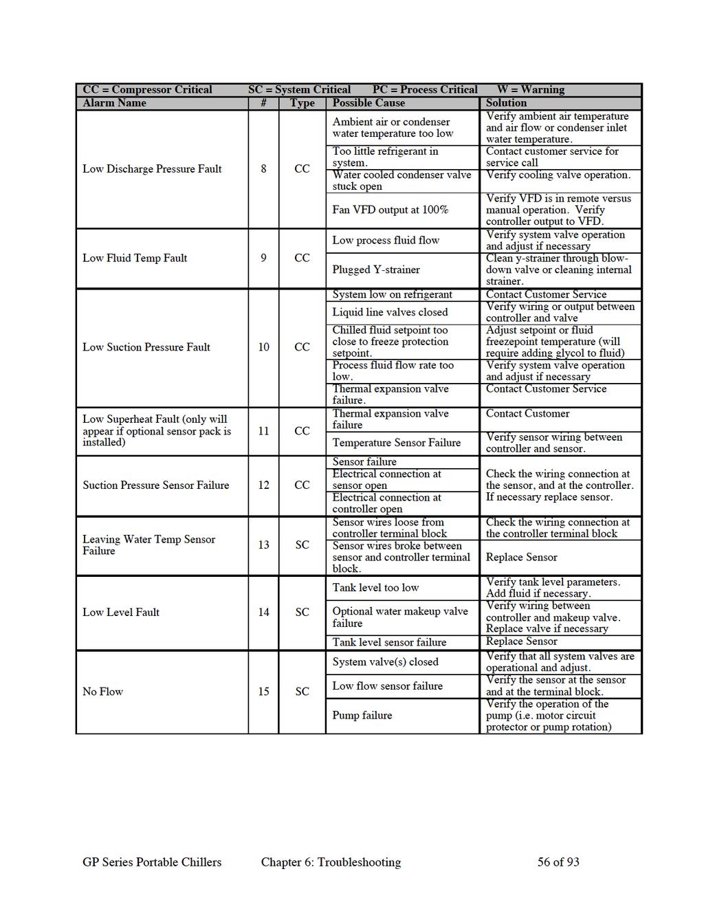
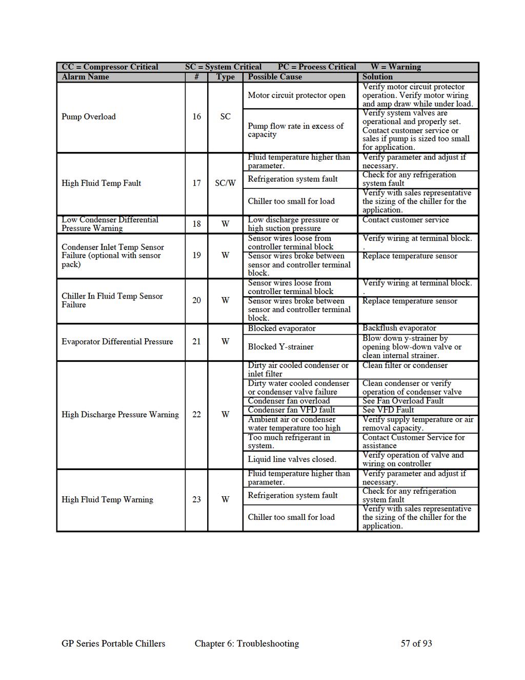
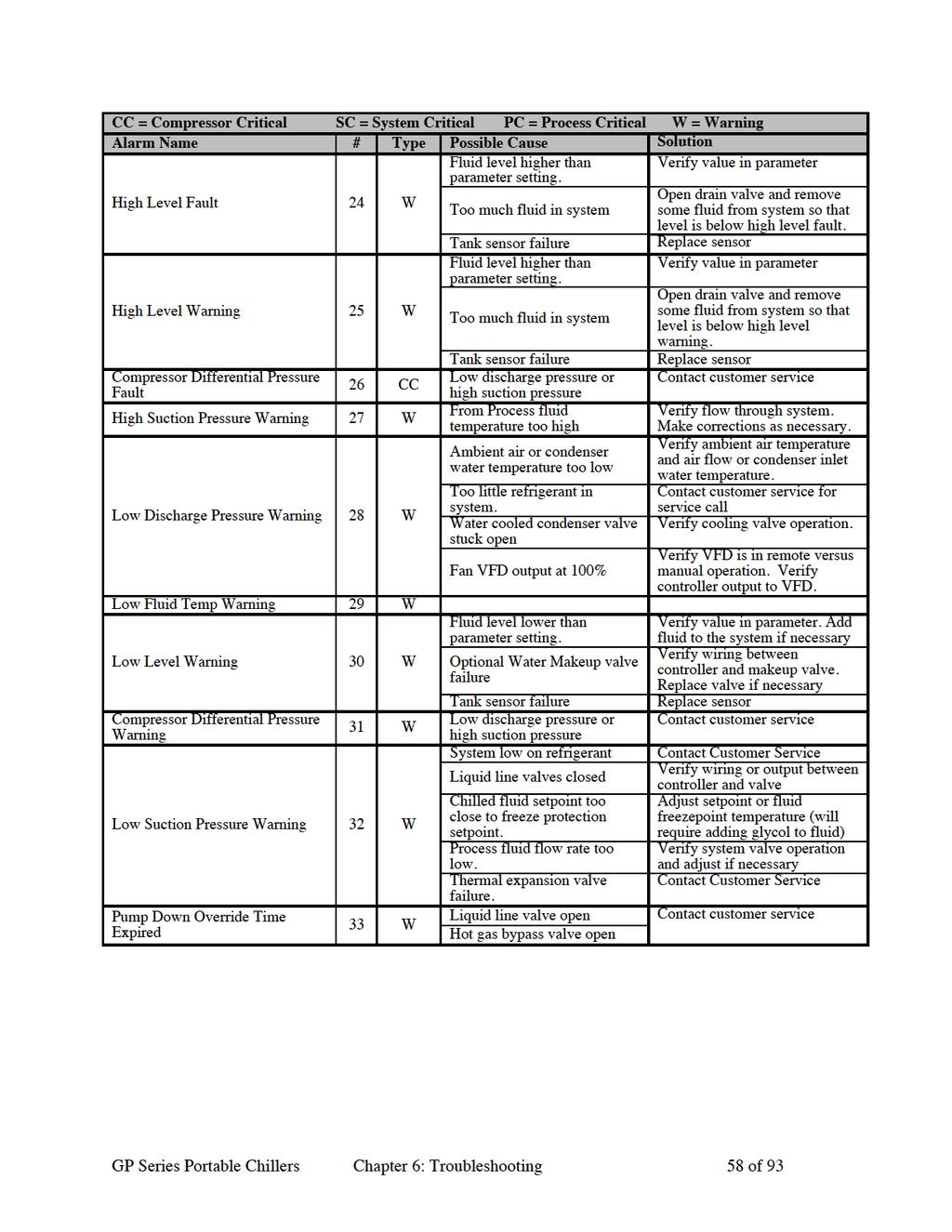
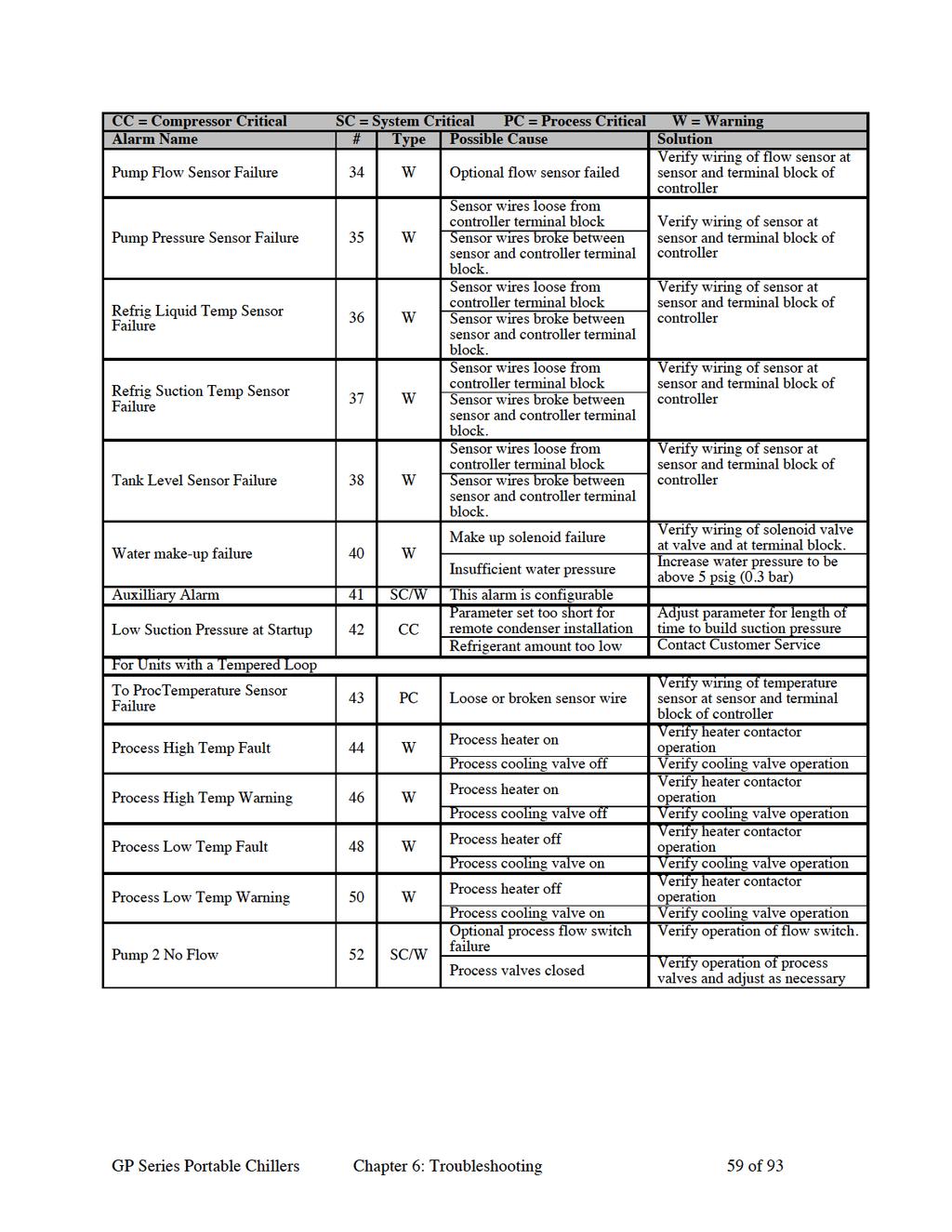
54 Chapter 6: Troubleshooting Many problems that can occur while operating the chiller can be avoided by following the recommended installation, operation, and maintenance outlined within this manual. If you do have a problem this Chapter will help you determine the cause and the potential solution. Before beginning the troubleshooting process Locate all wiring, piping, and assembly drawings that were shipped with the chiller. The diagrams will note any custom options not covered in this manual. Locate all manuals for any equipment that this chiller is connected to as they may provide additional information to solve the problem. Improper installation, operation, or any servicing may result in damage or personal injusry This chiller should only be installed, operated, and maintained by qualified technical personnel who are familiar with the construction, operation, and potential hazards. All wiring, disconnects, and over-current protection devices should be installed by a qualified electrician in accordance will all local codes and ordinances in your region. Electrical Hazard Before performing any service on this equipment disconnect and lockout all electrical sources to prevent injury from unepected energization or startup. Follow all safety rules when performing any maintenance or service to this equipment. Refrigeration Hazard Only certified refrigeration technicians should perform any refrigeration related maintenance. Hot Surfaces Protect yourself from hot surfaces when working on the refrigeration or process temperature sections of this equipment. These devices can reach temperatures of 180 F (82 C). Allow the equipment to cool prior to performing any maintenance or service. 6-1 Identifying the Cause of a Problem Types of conditions the user may see include alarm conditions and control problems. Alarm Conditions When an alarm condition occurs the button backlight will flash, and if the optional audible/visual alarm is installed the strobe and horn will energize. The light and horn will remain on until the condition is corrected. Pressing the enter button will silence the audible alarm, but the strobe will continue to flash. The display will show the cause the alarm and will indicate a possible solution. To accept the alarm press, and follow the suggested solution to correct the alarm condition. The following table shows the possible alarm messages that could appear on the display. GP Series Portable Chillers Chapter 6: Troubleshooting 54 of 93

55
56
57
58
59
60
61
62 Chapter 7: Appendi 7-1 Technical Assistance Parts and Service Department The ACS Customer Service Group will provide your company with genuine OEM quality parts manufactured to engineering design specifications, which will maimize your equipment s performance and efficiency. To assist in epediting your phone or fa order, please have the model and serial number of your unit when you contact us. A customer replacement parts list is included in this manual for your convenience. ACS welcomes inquiries on all your parts needs and is dedicated to providing ecellent customer service. For immediate assistance, please contact: North, Central and South America, 8am 5pm CST +1 (800) for drying, conveying, heating and cooling and automation. For size reduction: +1 (800) North America, emergencies after 5pm CST (847) North America acsuscanadacustserv@corp .com Meico, Central & South America acslatinamericacustserv@corp .com Europe, Middle East & Africa acseuropecustserv@corp .com India acsindiacustserv@corp .com Asia/Australia acsasiacustserv@corp .com Sales and Contracting Department Our products are sold by a worldwide network of independent sales representatives. Contact our Sales Department for the name of the sales representative nearest you. Let us install your system. The Contract Department offers any or all of these services: project planning; system packages including drawings; equipment, labor, and construction materials; and union or non-union installations. For assistance with your sales or system contracting needs please Call: North, Central and South America +1 (262) or +1 (847) Monday Friday, 8am 5pm CST Europe/Middle East/Africa India Asia/Australia Facilities: ACS offers facilities around the world to service you no matter where you are located. For more information, please visit us at United States: Asia/Australia: ACS Schaumburg-Corporate Offices 1100 E. Woodfield Road Suite 588 Schaumburg, IL Phone: Fa: ACS New Berlin- Manufacturing Facility 2900 S. 160 th Street ACS Warsaw New Berlin, WI GP Series Portable Chillers Chapter 7: Ul. Appendi Działkowa of 93 Phone : Fa: ACS Suzhou 109 Xingpu Road SIP Suzhou, China Phone: Fa: Europe/Middle East/Africa: Warszawa Phone: Fa: India ACS India Gat No. 191/1, Sandbhor Comple Mhalunge, Chakan, Tal Khed, Dist. Pune , India Phone: Fa:
63 Specifications Air-Cooled Portable Chillers Nominal operating parameters for air-cooled models are 50ºF (10ºC) leaving water temperature at 2.4 gpm per ton (9.1 lpm per kw) with 95ºF (35ºC) ambient air. For 50 Hz applications, multiply capacity by Nominal 60 Hz capacity flow rate must be maintained. GPAC-20 PERFORMANCE (NOMINAL DESIGN CONDITIONS) COOLING CAPACITY 4.65 TONS ALTITUDE SEA LEVEL COOLANT SUPPLY TEMPERATURE 50 F COMPRESSOR POWER 4936 WATTS AMBIENT AIR TEMPERATURE 95 F EER BTU/WATT COOLANT WATER CONDENSER AIR FLOW 4230 CFM COOLANT FLOW 11 GPM SOUND POWER LEVEL 86 dba UNIT PRESSURE DROP 7 PSID SOUND PRESSURE 1 METER dba OPERATING PARAMETERS COOLANT SUPPLY TEMPERATURE F COOLANT FLOW 6-24 GPM AMBIENT AIR TEMPERATURE F MINIMUM LOAD TONS SPECIFICATIONS COMPRESSOR SCROLL EVAPORATOR FILTER 20 MESH COOLANT PUMP STAINLESS STEEL CENTRIFUGAL COOLANT CIRCUIT NON-FERROUS EVAPORATOR BRAZED PLATE CAPACITY CONTROL HOT GAS BYPASS CONDENSER ALUMINUM REFRIGERANT 3 LBS R-410A CONDENSER FANS 24 INCH AXIAL FRAME GALVANIZED STEEL CONDENSER FAN MOTOR 1/2 HP OAO, 1140 RPM PANELS POWDER COATED STEEL RESERVOIR 20 GALLON POLYETHYLENE WEIGHT (OPERATING) 690 LBS POWER 460V/3PH/60HZ WEIGHT (SHIPPING) 520 LBS CONTROL CIRCUIT 120 VDC ELECTRICAL ENCLOSURE NEMA 12 COMPRESSOR FULL LOAD AMPS 10.7 AMPS CONTROL MICROPROCESSOR GPAC-30 PERFORMANCE (NOMINAL DESIGN CONDITIONS) COOLING CAPACITY 7.30 TONS ALTITUDE SEA LEVEL COOLANT SUPPLY TEMPERATURE 50 F COMPRESSOR POWER 7579 WATTS AMBIENT AIR TEMPERATURE 95 F EER BTU/WATT COOLANT WATER CONDENSER AIR FLOW 6343 CFM COOLANT FLOW 18 GPM SOUND POWER LEVEL 92 dba UNIT PRESSURE DROP 7 PSID SOUND PRESSURE 1 METER dba OPERATING PARAMETERS COOLANT SUPPLY TEMPERATURE F COOLANT FLOW 9-36 GPM AMBIENT AIR TEMPERATURE F MINIMUM LOAD TONS SPECIFICATIONS COMPRESSOR SCROLL EVAPORATOR FILTER 20 MESH COOLANT PUMP STAINLESS STEEL CENTRIFUGAL COOLANT CIRCUIT NON-FERROUS EVAPORATOR BRAZED PLATE CAPACITY CONTROL HOT GAS BYPASS CONDENSER ALUMINUM REFRIGERANT 4 LBS R-410A CONDENSER FANS 24 INCH AXIAL FRAME GALVANIZED STEEL CONDENSER FAN MOTOR 1 HP OAO, 1140 RPM PANELS POWDER COATED STEEL RESERVOIR 20 GALLON POLYETHYLENE WEIGHT (OPERATING) 870 LBS POWER 460V/3PH/60HZ WEIGHT (SHIPPING) 700 LBS CONTROL CIRCUIT 120 VDC ELECTRICAL ENCLOSURE NEMA 12 COMPRESSOR FULL LOAD AMPS 16.4 AMPS CONTROL MICROPROCESSOR GP Series Portable Chillers Chapter 7: Appendi 63 of 93
64 GPAC-40 PERFORMANCE (NOMINAL DESIGN CONDITIONS) COOLING CAPACITY 9.91 TONS ALTITUDE SEA LEVEL COOLANT SUPPLY TEMPERATURE 50 F COMPRESSOR POWER WATTS AMBIENT AIR TEMPERATURE 95 F EER BTU/WATT COOLANT WATER CONDENSER AIR FLOW 8458 CFM COOLANT FLOW 24 GPM SOUND POWER LEVEL 87 dba UNIT PRESSURE DROP 7 PSID SOUND PRESSURE 1 METER dba OPERATING PARAMETERS COOLANT SUPPLY TEMPERATURE F COOLANT FLOW GPM AMBIENT AIR TEMPERATURE F MINIMUM LOAD TONS SPECIFICATIONS COMPRESSOR SCROLL EVAPORATOR FILTER 20 MESH COOLANT PUMP STAINLESS STEEL CENTRIFUGAL COOLANT CIRCUIT NON-FERROUS EVAPORATOR BRAZED PLATE CAPACITY CONTROL HOT GAS BYPASS CONDENSER ALUMINUM REFRIGERANT 6 LBS R-410A CONDENSER FANS 32 INCH AXIAL FRAME GALVANIZED STEEL CONDENSER FAN MOTOR 1 HP OAO, 1140 RPM PANELS POWDER COATED STEEL RESERVOIR 40 GALLON POLYETHYLENE WEIGHT (OPERATING) 1090 LBS POWER 460V/3PH/60HZ WEIGHT (SHIPPING) 760 LBS CONTROL CIRCUIT 120 VDC ELECTRICAL ENCLOSURE NEMA 12 COMPRESSOR FULL LOAD AMPS 20 AMPS CONTROL MICROPROCESSOR GPAC-50 PERFORMANCE (NOMINAL DESIGN CONDITIONS) COOLING CAPACITY TONS ALTITUDE SEA LEVEL COOLANT SUPPLY TEMPERATURE 50 F COMPRESSOR POWER WATTS AMBIENT AIR TEMPERATURE 95 F EER BTU/WATT COOLANT WATER CONDENSER AIR FLOW CFM COOLANT FLOW 36 GPM SOUND POWER LEVEL 93 dba UNIT PRESSURE DROP 7 PSID SOUND PRESSURE 1 METER dba OPERATING PARAMETERS COOLANT SUPPLY TEMPERATURE F COOLANT FLOW GPM AMBIENT AIR TEMPERATURE F MINIMUM LOAD TONS SPECIFICATIONS COMPRESSOR SCROLL EVAPORATOR FILTER 20 MESH COOLANT PUMP STAINLESS STEEL CENTRIFUGAL COOLANT CIRCUIT NON-FERROUS EVAPORATOR BRAZED PLATE CAPACITY CONTROL HOT GAS BYPASS CONDENSER ALUMINUM REFRIGERANT 8 LBS R-410A CONDENSER FANS 32 INCH AXIAL FRAME GALVANIZED STEEL CONDENSER FAN MOTOR 2 HP OAO, 1140 RPM PANELS POWDER COATED STEEL RESERVOIR 40 GALLON POLYETHYLENE WEIGHT (OPERATING) 1290 LBS POWER 460V/3PH/60HZ WEIGHT (SHIPPING) 950 LBS CONTROL CIRCUIT 120 VDC ELECTRICAL ENCLOSURE NEMA 12 COMPRESSOR FULL LOAD AMPS 30 AMPS CONTROL MICROPROCESSOR GP Series Portable Chillers Chapter 7: Appendi 64 of 93
65 GPAC-70 PERFORMANCE (NOMINAL DESIGN CONDITIONS) COOLING CAPACITY TONS ALTITUDE SEA LEVEL COOLANT SUPPLY TEMPERATURE 50 F COMPRESSOR POWER WATTS AMBIENT AIR TEMPERATURE 95 F EER BTU/WATT COOLANT WATER CONDENSER AIR FLOW CFM COOLANT FLOW 48 GPM SOUND POWER LEVEL 89 dba UNIT PRESSURE DROP 7 PSID SOUND PRESS 1 METER dba OPERATING PARAMETERS COOLANT SUPPLY TEMPERATURE F COOLANT FLOW GPM AMBIENT AIR TEMPERATURE F MINIMUM LOAD 4.03 TONS SPECIFICATIONS COMPRESSOR SCROLL EVAPORATOR FILTER 20 MESH COOLANT PUMP STAINLESS STEEL CENTRIFUGAL COOLANT CIRCUIT NON-FERROUS EVAPORATOR BRAZED PLATE CAPACITY CONTROL HOT GAS BYPASS CONDENSER ALUMINUM REFRIGERANT 12 LBS R-410A CONDENSER FANS (2) 24 INCH AXIAL FRAME GALVANIZED STEEL CONDENSER FAN MOTOR (2) 1/2 HP OAO, 1140 RPM PANELS POWDER COATED STEEL RESERVOIR 70 GALLON POLYETHYLENE WEIGHT (OPERATING) 2180 LBS POWER 460V/3PH/60HZ WEIGHT (SHIPPING) 1520 LBS CONTROL CIRCUIT 24/120 VAC ELECTRICAL ENCLOSURE NEMA 12 COMPRESSOR RATED LOAD AMPS 17.9 AMPS EACH CONTROL MICROPROCESSOR GPAC-90 PERFORMANCE (NOMINAL DESIGN CONDITIONS) COOLING CAPACITY TONS ALTITUDE SEA LEVEL COOLANT SUPPLY TEMPERATURE 50 F COMPRESSOR POWER WATTS AMBIENT AIR TEMPERATURE 95 F EER BTU/WATT COOLANT WATER CONDENSER AIR FLOW CFM COOLANT FLOW 61 GPM SOUND POWER LEVEL 95 dba UNIT PRESSURE DROP 7 PSID SOUND PRESS 1 METER dba OPERATING PARAMETERS COOLANT SUPPLY TEMPERATURE F COOLANT FLOW GPM AMBIENT AIR TEMPERATURE F MINIMUM LOAD 5.09 TONS SPECIFICATIONS COMPRESSOR SCROLL EVAPORATOR FILTER 20 MESH COOLANT PUMP STAINLESS STEEL CENTRIFUGAL COOLANT CIRCUIT NON-FERROUS EVAPORATOR BRAZED PLATE CAPACITY CONTROL HOT GAS BYPASS CONDENSER ALUMINUM REFRIGERANT 12 LBS R-410A CONDENSER FANS (2) 32 INCH AXIAL FRAME GALVANIZED STEEL CONDENSER FAN MOTOR (2) 2 HP OAO, 1140 RPM PANELS POWDER COATED STEEL RESERVOIR 70 GALLON POLYETHYLENE WEIGHT (OPERATING) 2580 LBS POWER 460V/3PH/60HZ WEIGHT (SHIPPING) 1900 LBS CONTROL CIRCUIT 24/120 VAC ELECTRICAL ENCLOSURE NEMA 12 COMPRESSOR RATED LOAD AMPS 23.1 AMPS EACH CONTROL MICROPROCESSOR GP Series Portable Chillers Chapter 7: Appendi 65 of 93
66 GPAC-105 PERFORMANCE (NOMINAL DESIGN CONDITIONS) COOLING CAPACITY TONS ALTITUDE SEA LEVEL COOLANT SUPPLY TEMPERATURE 50 F COMPRESSOR POWER WATTS AMBIENT AIR TEMPERATURE 95 F EER BTU/WATT COOLANT WATER CONDENSER AIR FLOW CFM COOLANT FLOW 72 GPM SOUND POWER LEVEL 95 dba UNIT PRESSURE DROP 7 PSID SOUND PRESS 1 METER dba OPERATING PARAMETERS COOLANT SUPPLY TEMPERATURE F COOLANT FLOW GPM AMBIENT AIR TEMPERATURE F MINIMUM LOAD 6.04 TONS SPECIFICATIONS COMPRESSOR SCROLL EVAPORATOR FILTER 20 MESH COOLANT PUMP STAINLESS STEEL CENTRIFUGAL COOLANT CIRCUIT NON-FERROUS EVAPORATOR BRAZED PLATE CAPACITY CONTROL HOT GAS BYPASS CONDENSER ALUMINUM REFRIGERANT 16 LBS R-410A CONDENSER FANS (2) 32 INCH AXIAL FRAME GALVANIZED STEEL CONDENSER FAN MOTOR (2) 2 HP OAO, 1140 RPM PANELS POWDER COATED STEEL RESERVOIR 70 GALLON POLYETHYLENE WEIGHT (OPERATING) 2580 LBS POWER 460V/3PH/60HZ WEIGHT (SHIPPING) 1900 LBS CONTROL CIRCUIT 24/120 VAC ELECTRICAL ENCLOSURE NEMA 12 COMPRESSOR RATED LOAD AMPS 26.9 AMPS EACH CONTROL MICROPROCESSOR GPAC-140 PERFORMANCE (NOMINAL DESIGN CONDITIONS) COOLING CAPACITY 40 TONS ALTITUDE SEA LEVEL COOLANT SUPPLY TEMPERATURE 50 F COMPRESSOR POWER WATTS AMBIENT AIR TEMPERATURE 95 F EER BTU/WATT COOLANT WATER CONDENSER AIR FLOW CFM COOLANT FLOW 96 GPM SOUND POWER LEVEL 98 dba UNIT PRESSURE DROP 7 PSID SOUND PRESS 1 METER dba OPERATING PARAMETERS COOLANT SUPPLY TEMPERATURE F COOLANT FLOW GPM AMBIENT AIR TEMPERATURE F MINIMUM LOAD 8.00 TONS SPECIFICATIONS COMPRESSOR SCROLL EVAPORATOR FILTER 20 MESH COOLANT PUMP STAINLESS STEEL CENTRIFUGAL COOLANT CIRCUIT NON-FERROUS EVAPORATOR BRAZED PLATE CAPACITY CONTROL HOT GAS BYPASS CONDENSER ALUMINUM REFRIGERANT 18 LBS R-410A CONDENSER FANS (3) 32 INCH AXIAL FRAME GALVANIZED STEEL CONDENSER FAN MOTOR (3) 2 HP OAO, 1140 RPM PANELS POWDER COATED STEEL RESERVOIR 140 GALLON POLYETHYLENE WEIGHT (OPERATING) 3870 LBS POWER 460V/3PH/60HZ WEIGHT (SHIPPING) 2850 LBS CONTROL CIRCUIT 24/120 VAC ELECTRICAL ENCLOSURE NEMA 12 COMPRESSOR RATED LOAD AMPS 30.4 AMPS EACH CONTROL MICROPROCESSOR GP Series Portable Chillers Chapter 7: Appendi 66 of 93
67 GPAC-175 PERFORMANCE (NOMINAL DESIGN CONDITIONS) COOLING CAPACITY TONS ALTITUDE SEA LEVEL COOLANT SUPPLY TEMPERATURE 50 F COMPRESSOR POWER WATTS AMBIENT AIR TEMPERATURE 95 F EER BTU/WATT COOLANT WATER CONDENSER AIR FLOW CFM COOLANT FLOW 118 GPM SOUND POWER LEVEL 98 dba UNIT PRESSURE DROP 7 PSID SOUND PRESS 1 METER dba OPERATING PARAMETERS COOLANT SUPPLY TEMPERATURE F COOLANT FLOW GPM AMBIENT AIR TEMPERATURE F MINIMUM LOAD 9.88 TONS SPECIFICATIONS COMPRESSOR SCROLL EVAPORATOR FILTER 20 MESH COOLANT PUMP STAINLESS STEEL CENTRIFUGAL COOLANT CIRCUIT NON-FERROUS EVAPORATOR BRAZED PLATE CAPACITY CONTROL HOT GAS BYPASS CONDENSER ALUMINUM REFRIGERANT 24 LBS R-410A CONDENSER FANS (3) 32 INCH AXIAL FRAME GALVANIZED STEEL CONDENSER FAN MOTOR (3) 2 HP OAO, 1140 RPM PANELS POWDER COATED STEEL RESERVOIR 140 GALLON POLYETHYLENE WEIGHT (OPERATING) 3870 LBS POWER 460V/3PH/60HZ WEIGHT (SHIPPING) 2850 LBS CONTROL CIRCUIT 24/120 VAC ELECTRICAL ENCLOSURE NEMA 12 COMPRESSOR RATED LOAD AMPS 41.9 AMPS EACH CONTROL MICROPROCESSOR GPAC-210 PERFORMANCE (NOMINAL DESIGN CONDITIONS) COOLING CAPACITY TONS ALTITUDE SEA LEVEL COOLANT SUPPLY TEMPERATURE 50 F COMPRESSOR POWER WATTS AMBIENT AIR TEMPERATURE 95 F EER BTU/WATT COOLANT WATER CONDENSER AIR FLOW CFM COOLANT FLOW 153 GPM SOUND POWER LEVEL 99 dba UNIT PRESSURE DROP 7 PSID SOUND PRESS 1 METER dba OPERATING PARAMETERS COOLANT SUPPLY TEMPERATURE F COOLANT FLOW GPM AMBIENT AIR TEMPERATURE F MINIMUM LOAD TONS SPECIFICATIONS COMPRESSOR SCROLL EVAPORATOR FILTER 20 MESH COOLANT PUMP STAINLESS STEEL CENTRIFUGAL COOLANT CIRCUIT NON-FERROUS EVAPORATOR BRAZED PLATE CAPACITY CONTROL HOT GAS BYPASS CONDENSER ALUMINUM REFRIGERANT 32 LBS R-410A CONDENSER FANS (4) 32 INCH AXIAL FRAME GALVANIZED STEEL CONDENSER FAN MOTOR (4) 2 HP OAO, 1140 RPM PANELS POWDER COATED STEEL RESERVOIR 140 GALLON POLYETHYLENE WEIGHT (OPERATING) 5160 LBS POWER 460V/3PH/60HZ WEIGHT (SHIPPING) 3800 LBS CONTROL CIRCUIT 24/120 VAC ELECTRICAL ENCLOSURE NEMA 12 COMPRESSOR RATED LOAD AMPS 54.5 AMPS EACH CONTROL MICROPROCESSOR GP Series Portable Chillers Chapter 7: Appendi 67 of 93
68 Water-Cooled Portable Chillers Nominal operating parameters for water-cooled models are 50ºF (10ºC) leaving water temperature at 2.4 gpm per ton (9.1 lpm per kw) with 85ºF (29ºC) tower water. For 50 Hz applications, multiply capacity by Nominal 60 Hz capacity flow rate must be maintained. GPWC-20 PERFORMANCE (NOMINAL DESIGN CONDITIONS, 60 HZ) COOLING CAPACITY 5.12 TONS ALTITUDE SEA LEVEL COOLANT SUPPLY TEMPERATURE 50 F COMPRESSOR POWER 4064 WATTS CONDENSER INLET WATER TEMPERATURE 85 F EER BTU/WATT COOLANT WATER CONDENSER WATER FLOW 15.9 GPM COOLANT FLOW 13 GPM SOUND POWER LEVEL dba UNIT PRESSURE DROP 7 PSID SOUND PRESSURE 1 METER dba OPERATING PARAMETERS COOLANT SUPPLY TEMPERATURE F COOLANT FLOW 6-24 GPM CONDENSER INLET WATER TEMPERATURE F MINIMUM LOAD 1.06 TONS SPECIFICATIONS COMPRESSOR SCROLL EVAPORATOR FILTER 20 MESH COOLANT PUMP STAINLESS STEEL CENTRIFUGAL COOLANT CIRCUIT NON-FERROUS EVAPORATOR BRAZED PLATE CAPACITY CONTROL HOT GAS BYPASS CONDENSER TUBE IN TUBE REFRIGERANT 3 LBS R-410A FRAME PANELS GALVANIZED STEEL POWDER COATED STEEL RESERVOIR 20 GALLON POLYETHYLENE WEIGHT (OPERATING) 690 LBS POWER 460V/3PH/60HZ WEIGHT (SHIPPING) 520 LBS CONTROL CIRCUIT 120 VDC ELECTRICAL ENCLOSURE NEMA 12 COMPRESSOR FULL LOAD AMPS 10.7 AMPS CONTROL MICROPROCESSOR GPWC-30 PERFORMANCE (NOMINAL DESIGN CONDITIONS) COOLING CAPACITY 7.98 TONS ALTITUDE SEA LEVEL COOLANT SUPPLY TEMPERATURE 50 F COMPRESSOR POWER 6416 WATTS CONDENSER INLET WATER TEMPERATURE 85 F EER BTU/WATT COOLANT WATER CONDENSER WATER FLOW GPM COOLANT FLOW 20 GPM SOUND POWER LEVEL dba SOUND PRESSURE 1 UNIT PRESSURE DROP 7 PSID dba METER OPERATING PARAMETERS COOLANT SUPPLY TEMPERATURE F COOLANT FLOW 9-36 GPM CONDENSER INLET WATER TEMPERATURE F MINIMUM LOAD TONS SPECIFICATIONS COMPRESSOR SCROLL EVAPORATOR FILTER 20 MESH COOLANT PUMP STAINLESS STEEL CENTRIFUGAL COOLANT CIRCUIT NON-FERROUS EVAPORATOR BRAZED PLATE CAPACITY CONTROL HOT GAS BYPASS CONDENSER TUBE IN TUBE REFRIGERANT 4 LBS R-410A FRAME PANELS GALVANIZED STEEL POWDER COATED STEEL RESERVOIR 20 GALLON POLYETHYLENE WEIGHT (OPERATING) 870 LBS POWER 460V/3PH/60HZ WEIGHT (SHIPPING) 700 LBS CONTROL CIRCUIT 120 VDC ELECTRICAL ENCLOSURE NEMA 12 COMPRESSOR FULL LOAD AMPS 16.4 AMPS CONTROL MICROPROCESSOR GP Series Portable Chillers Chapter 7: Appendi 68 of 93
69 GPWC-40 PERFORMANCE (NOMINAL DESIGN CONDITIONS) COOLING CAPACITY TONS ALTITUDE SEA LEVEL COOLANT SUPPLY TEMPERATURE 50 F COMPRESSOR POWER 8450 WATTS CONDENSER INLET WATER TEMPERATURE 85 F EER BTU/WATT COOLANT WATER CONDENSER WATER FLOW GPM COOLANT FLOW 27 GPM SOUND POWER LEVEL dba SOUND PRESSURE 1 UNIT PRESSURE DROP 7 PSID dba METER OPERATING PARAMETERS COOLANT SUPPLY TEMPERATURE F COOLANT FLOW GPM CONDENSER INLET WATER TEMPERATURE F MINIMUM LOAD TONS SPECIFICATIONS COMPRESSOR SCROLL EVAPORATOR FILTER 20 MESH COOLANT PUMP STAINLESS STEEL CENTRIFUGAL COOLANT CIRCUIT NON-FERROUS EVAPORATOR BRAZED PLATE CAPACITY CONTROL HOT GAS BYPASS CONDENSER TUBE IN TUBE REFRIGERANT 6 LBS R-410A FRAME PANELS GALVANIZED STEEL POWDER COATED STEEL RESERVOIR 40 GALLON POLYETHYLENE WEIGHT (OPERATING) 1090 LBS POWER 460V/3PH/60HZ WEIGHT (SHIPPING) 760 LBS CONTROL CIRCUIT 120 VDC ELECTRICAL ENCLOSURE NEMA 12 COMPRESSOR FULL LOAD AMPS 20 AMPS CONTROL MICROPROCESSOR GPWC-50 PERFORMANCE (NOMINAL DESIGN CONDITIONS) COOLING CAPACITY TONS ALTITUDE SEA LEVEL COOLANT SUPPLY TEMPERATURE 50 F COMPRESSOR POWER WATTS CONDENSER INLET WATER TEMPERATURE 85 F EER BTU/WATT COOLANT WATER CONDENSER WATER FLOW GPM COOLANT FLOW 40 GPM SOUND POWER LEVEL dba SOUND PRESSURE 1 UNIT PRESSURE DROP 7 PSID dba METER OPERATING PARAMETERS COOLANT SUPPLY TEMPERATURE F COOLANT FLOW GPM CONDENSER INLET WATER TEMPERATURE F MINIMUM LOAD TONS SPECIFICATIONS COMPRESSOR SCROLL EVAPORATOR FILTER 20 MESH COOLANT PUMP STAINLESS STEEL CENTRIFUGAL COOLANT CIRCUIT NON-FERROUS EVAPORATOR BRAZED PLATE CAPACITY CONTROL HOT GAS BYPASS CONDENSER TUBE IN TUBE REFRIGERANT 8 LBS R-410A FRAME PANELS GALVANIZED STEEL POWDER COATED STEEL RESERVOIR 40 GALLON POLYETHYLENE WEIGHT (OPERATING) 1290 LBS POWER 460V/3PH/60HZ WEIGHT (SHIPPING) 950 LBS CONTROL CIRCUIT 120 VDC ELECTRICAL ENCLOSURE NEMA 12 COMPRESSOR FULL LOAD AMPS 30 AMPS CONTROL MICROPROCESSOR GP Series Portable Chillers Chapter 7: Appendi 69 of 93
70 GPWC-70 PERFORMANCE (NOMINAL DESIGN CONDITIONS) COOLING CAPACITY TONS ALTITUDE SEA LEVEL COOLANT SUPPLY TEMPERATURE 50 F COMPRESSOR POWER WATTS CONDENSER INLET WATER TEMP 85 F EER BTU/WATT COOLANT WATER CONDENSER WATER FLOW 68 GPM COOLANT FLOW 54 GPM SOUND POWER LEVEL 74 dba UNIT PRESSURE DROP 7 PSID SOUND PRESS 1 METER dba OPERATING PARAMETERS COOLANT SUPPLY TEMPERATURE F COOLANT FLOW GPM CONDENSER INLET WATER TEMP F MINIMUM LOAD 4.54 TONS SPECIFICATIONS COMPRESSOR SCROLL EVAPORATOR FILTER 20 MESH COOLANT PUMP SST CENTRIFUGAL COOLANT CIRCUIT NON-FERROUS EVAPORATOR BRAZED PLATE CAPACITY CONTROL HOT GAS BYPASS CONDENSER SHELL & TUBE REFRIGERANT 12 LBS R-410A FRAME GALVANIZED STEEL PANELS POWDER COATED STEEL RESERVOIR 70 GALLON POLYETHYLENE WEIGHT (OPERATING) 2180 LBS POWER 460V/3PH/60HZ WEIGHT (SHIPPING) 1520 LBS CONTROL CIRCUIT 24/120 VAC ELECTRICAL ENCLOSURE NEMA 12 COMPRESSOR RATED LOAD AMPS 17.9 AMPS EACH CONTROL MICROPROCESSOR GPWC-90 PERFORMANCE (NOMINAL DESIGN CONDITIONS) COOLING CAPACITY TONS ALTITUDE SEA LEVEL COOLANT SUPPLY TEMPERATURE 50 F COMPRESSOR POWER WATTS CONDENSER INLET WATER TEMP 85 F EER BTU/WATT COOLANT WATER CONDENSER WATER FLOW 85 GPM COOLANT FLOW 68 GPM SOUND POWER LEVEL 74 dba UNIT PRESSURE DROP 7 PSID SOUND PRESS 1 METER dba OPERATING PARAMETERS COOLANT SUPPLY TEMPERATURE F COOLANT FLOW GPM CONDENSER INLET WATER TEMP F MINIMUM LOAD 5.69 TONS SPECIFICATIONS COMPRESSOR SCROLL EVAPORATOR FILTER 20 MESH COOLANT PUMP SST CENTRIFUGAL COOLANT CIRCUIT NON-FERROUS EVAPORATOR BRAZED PLATE CAPACITY CONTROL HOT GAS BYPASS CONDENSER SHELL & TUBE REFRIGERANT 12 LBS R-410A FRAME GALVANIZED STEEL PANELS POWDER COATED STEEL RESERVOIR 70 GALLON POLYETHYLENE WEIGHT (OPERATING) 2580 LBS POWER 460V/3PH/60HZ WEIGHT (SHIPPING) 1900 LBS CONTROL CIRCUIT 24/120 VAC ELECTRICAL ENCLOSURE NEMA 12 COMPRESSOR RATED LOAD AMPS 23.1 AMPS EACH CONTROL MICROPROCESSOR GP Series Portable Chillers Chapter 7: Appendi 70 of 93
71 GPWC-105 PERFORMANCE (NOMINAL DESIGN CONDITIONS) COOLING CAPACITY TONS ALTITUDE SEA LEVEL COOLANT SUPPLY TEMPERATURE 50 F COMPRESSOR POWER WATTS CONDENSER INLET WATER TEMP 85 F EER BTU/WATT COOLANT WATER CONDENSER WATER FLOW 101 GPM COOLANT FLOW 80 GPM SOUND POWER LEVEL 76 dba UNIT PRESSURE DROP 7 PSID SOUND PRESS 1 METER dba OPERATING PARAMETERS COOLANT SUPPLY TEMPERATURE F COOLANT FLOW GPM CONDENSER INLET WATER TEMP F MINIMUM LOAD 6.73 TONS SPECIFICATIONS COMPRESSOR SCROLL EVAPORATOR FILTER 20 MESH COOLANT PUMP SST CENTRIFUGAL COOLANT CIRCUIT NON-FERROUS EVAPORATOR BRAZED PLATE CAPACITY CONTROL HOT GAS BYPASS CONDENSER SHELL & TUBE REFRIGERANT 16 LBS R-410A FRAME GALVANIZED STEEL PANELS POWDER COATED STEEL RESERVOIR 70 GALLON POLYETHYLENE WEIGHT (OPERATING) 2580 LBS POWER 460V/3PH/60HZ WEIGHT (SHIPPING) 1900 LBS CONTROL CIRCUIT 24/120 VAC ELECTRICAL ENCLOSURE NEMA 12 COMPRESSOR RATED LOAD AMPS 26.9 AMPS EACH CONTROL MICROPROCESSOR GPWC-140 PERFORMANCE (NOMINAL DESIGN CONDITIONS) COOLING CAPACITY TONS ALTITUDE SEA LEVEL COOLANT SUPPLY TEMPERATURE 50 F COMPRESSOR POWER WATTS CONDENSER INLET WATER TEMP 85 F EER BTU/WATT COOLANT WATER CONDENSER WATER FLOW 130 GPM COOLANT FLOW 104 GPM SOUND POWER LEVEL 79 dba UNIT PRESSURE DROP 7 PSID SOUND PRESS 1 METER dba OPERATING PARAMETERS COOLANT SUPPLY TEMPERATURE F COOLANT FLOW GPM CONDENSER INLET WATER TEMP F MINIMUM LOAD 8.67 TONS SPECIFICATIONS COMPRESSOR SCROLL EVAPORATOR FILTER 20 MESH COOLANT PUMP SST CENTRIFUGAL COOLANT CIRCUIT NON-FERROUS EVAPORATOR BRAZED PLATE CAPACITY CONTROL HOT GAS BYPASS CONDENSER SHELL & TUBE REFRIGERANT 18 LBS R-410A FRAME GALVANIZED STEEL PANELS POWDER COATED STEEL RESERVOIR 140 GALLON POLYETHYLENE WEIGHT (OPERATING) 3870 LBS POWER 460V/3PH/60HZ WEIGHT (SHIPPING) 2850 LBS CONTROL CIRCUIT 24/120 VAC ELECTRICAL ENCLOSURE NEMA 12 COMPRESSOR RATED LOAD AMPS 30.4 AMPS EACH CONTROL MICROPROCESSOR GP Series Portable Chillers Chapter 7: Appendi 71 of 93
72 GPWC-175 PERFORMANCE (NOMINAL DESIGN CONDITIONS) COOLING CAPACITY TONS ALTITUDE SEA LEVEL COOLANT SUPPLY TEMPERATURE 50 F COMPRESSOR POWER WATTS CONDENSER INLET WATER TEMP 85 F EER BTU/WATT COOLANT WATER CONDENSER WATER FLOW 163 GPM COOLANT FLOW 130 GPM SOUND POWER LEVEL 82 dba UNIT PRESSURE DROP 7 PSID SOUND PRESS 1 METER dba OPERATING PARAMETERS COOLANT SUPPLY TEMPERATURE F COOLANT FLOW GPM CONDENSER INLET WATER TEMP F MINIMUM LOAD TONS SPECIFICATIONS COMPRESSOR SCROLL EVAPORATOR FILTER 20 MESH COOLANT PUMP SST CENTRIFUGAL COOLANT CIRCUIT NON-FERROUS EVAPORATOR BRAZED PLATE CAPACITY CONTROL HOT GAS BYPASS CONDENSER SHELL & TUBE REFRIGERANT 24 LBS R-410A FRAME GALVANIZED STEEL PANELS POWDER COATED STEEL RESERVOIR 140 GALLON POLYETHYLENE WEIGHT (OPERATING) 3870 LBS POWER 460V/3PH/60HZ WEIGHT (SHIPPING) 2850 LBS CONTROL CIRCUIT 24/120 VAC ELECTRICAL ENCLOSURE NEMA 12 COMPRESSOR RATED LOAD AMPS 41.9 AMPS EACH CONTROL MICROPROCESSOR GPWC-210 PERFORMANCE (NOMINAL DESIGN CONDITIONS) COOLING CAPACITY TONS ALTITUDE SEA LEVEL COOLANT SUPPLY TEMPERATURE 50 F COMPRESSOR POWER WATTS CONDENSER INLET WATER TEMP 85 F EER BTU/WATT COOLANT WATER CONDENSER WATER FLOW 212 GPM COOLANT FLOW 169 GPM SOUND POWER LEVEL 81 dba UNIT PRESSURE DROP 7 PSID SOUND PRESS 1 METER dba OPERATING PARAMETERS COOLANT SUPPLY TEMPERATURE F COOLANT FLOW GPM CONDENSER INLET WATER TEMP F MINIMUM LOAD TONS SPECIFICATIONS COMPRESSOR SCROLL EVAPORATOR FILTER 20 MESH COOLANT PUMP SST CENTRIFUGAL COOLANT CIRCUIT NON-FERROUS EVAPORATOR BRAZED PLATE CAPACITY CONTROL HOT GAS BYPASS CONDENSER SHELL & TUBE REFRIGERANT 32 LBS R-410A FRAME GALVANIZED STEEL PANELS POWDER COATED STEEL RESERVOIR 140 GALLON POLYETHYLENE WEIGHT (OPERATING) 5160 LBS POWER 460V/3PH/60HZ WEIGHT (SHIPPING) 3800 LBS CONTROL CIRCUIT 24/120 VAC ELECTRICAL ENCLOSURE NEMA 12 COMPRESSOR RATED LOAD AMPS 54.5 AMPS EACH CONTROL MICROPROCESSOR GP Series Portable Chillers Chapter 7: Appendi 72 of 93
73
74
75
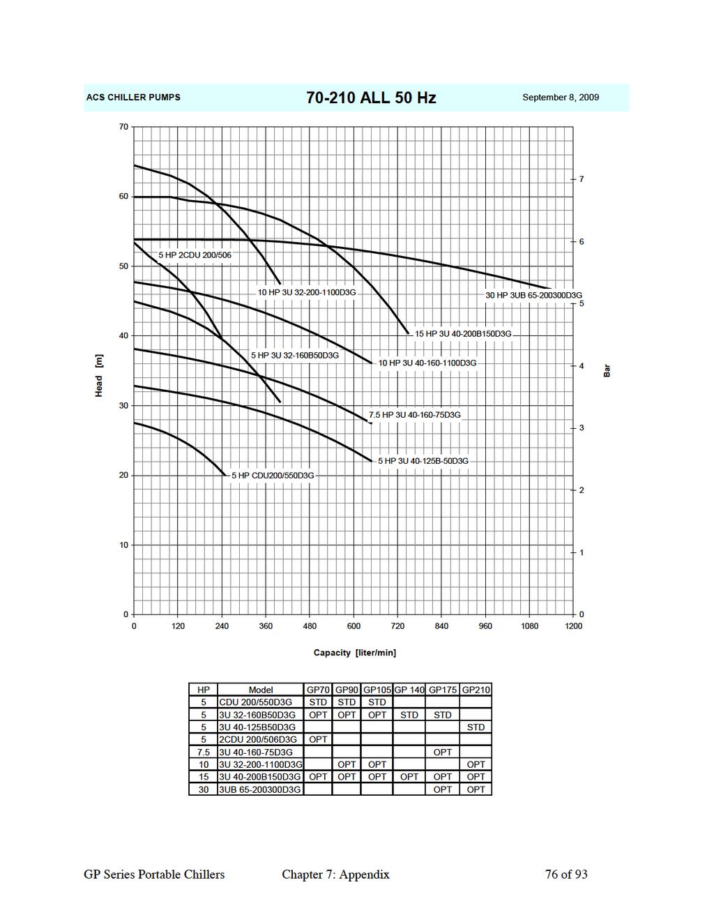
76
GP SERIES Packaged Chillers
 Material Handling Process Cooling Temperature Control Size Reduction Temperature Control Process Cooling Material Handling Size Reduction GP SERIES Packaged Chillers Precision Comprehensive Engineered
PARALLEL RACK SYSTEM INSTALLATION & OPERATIONS MANUAL With Master Rack Compressor Sequencer
 PARALLEL RACK SYSTEM INSTALLATION & OPERATIONS MANUAL With Master Rack Compressor Sequencer 5/16 Rev. A 57-02509 2 Contents INTRODUCTION... 4 WARNING LABELS AND SAFETY INSTRUCTIONS... 5 PS SERIES PARALLEL
.2 Section Waste Management and Disposal.
 Issued 2005/06/01 Section 15624 Packaged Rotary Screw Water Chillers Page 1 of 5 PART 1 General 1.1 RELATED SECTIONS.1 Section 01330 Submittal Procedures..2 Section 01355 Waste Management and Disposal..3
Liebert CSU3000 Chiller
 CSI 15620 - Packaged Water Chillers Liebert CSU3000 Chiller Guide Specifications for 7.5-37 Ton CS/CD/CT Models 1.0 GENERAL 1.1 CS/CD MODELS The main-frame coolant supply unit shall be a Liebert Model,
THE PRODUCTS YOU NEED. THE QUALITY YOU WANT. THE INNOVATION YOU DESERVE.
 THE PRODUCTS YOU NEED. THE QUALITY YOU WANT. THE INNOVATION YOU DESERVE. Portable Chillers s P O RTA B L E C H I L L E R S SMC Series 1/2 to 3-1/2 HP Portable Chiller SMC ½ to 1½ HP Features: Environmentally
PDF Created with deskpdf PDF Writer - Trial ::
 Instruction Manual Index Introduction Uncrating and Checking for Damage Locating Your Unit Installation Fill Tank Process Connections Pre Startup Startup Sequence Trouble Shooting Chart Operating Lights
PS SERIES PARALLEL RACK SYSTEM GLYCOL CHILLER START UP GUIDE. Master Rack Compressor Sequencer 7/21/2017
 PS SERIES PARALLEL RACK SYSTEM GLYCOL CHILLER START UP GUIDE Master Rack Compressor Sequencer 7/21/2017 1 2 Contents INTRODUCTION... 4 WARNING LABELS AND SAFETY INSTRUCTIONS... 5 PARALLEL RACK NOMENCLATURE...
MACH N-407 Heat Pump Air-Cooled Chiller
 MACH060-01-N-407 Heat Pump Air-Cooled Chiller Heat Pump Air-Cooled Chillers for Global Residential and Light Commercial Microclimates MACH NOMENCLATURE BREAKDOWN MACH-060-01 - N - 407 Refrigerant Type
B. Unit construction shall comply with ASHRAE 15 Safety Code, NEC, and ASME applicable codes (U.S.A. codes).
.") Guide Specifications PART 1 GENERAL 1.01 SYSTEM DESCRIPTION Microprocessor controlled, air-cooled liquid chiller utilizing scroll compressors, low sound fans, hydronic pump system and optional fluid storage
Guide Specifications PART 1 GENERAL 1.01 SYSTEM DESCRIPTION Microprocessor controlled, air-cooled liquid chiller utilizing scroll compressors, low sound fans, hydronic pump system and optional fluid storage
C. ASME Compliance: Fabricate and label water chiller heat exchangers to comply with ASME Boiler and Pressure Vessel Code: Section VIII, Division 1.
 SECTION 236426 - ROTARY-SCREW WATER CHILLERS PART 1 - GENERAL 1.1 SUMMARY A. This Section includes packaged, water cooled or air cooled as scheduled, electric-motor-driven, rotary-screw water chillers
THE PRODUCTS YOU NEED. THE QUALITY YOU WANT. THE INNOVATION YOU DESERVE.
 THE PRODUCTS YOU NEED. THE QUALITY YOU WANT. THE INNOVATION YOU DESERVE. Central Chillers & Pump Tanks C E N T R A L C H I L L E R S 30RAP Series Central Chillers 10-60 Tons 30RAP Series air-cooled central
Precise Temperature Control; Compact Footprint
 Precise Temperature Control; Compact Footprint The Conair EP1 Series Portable Chillers are designed for 1 to 3 ton applications. Available as air-cooled or water-cooled, with pump sizes from 1/4 to 3 Hp
Installation Operation Maintenance
 Installation Operation Maintenance Series R Air-Cooled Helical Rotary Liquid Chiller RTAD 085-180 (50Hz) Standard, Free Cooling and Heat Recovery models RTAD-SVX01F-E4 General information Foreword These
TITAN SERIES Complete Central Chiller & Pump Tank Package 20 to 70 Tons 20 F to 70 F
 Temperature Control Units Water & Oil - F Portable Chillers Air & Water-Cooled - 7 F Central Chillers Air & Water-Cooled Packages & Modules - 7 F Pump Tank Stations Chilled or Tower Water - gallons Cooling
MDX. Non-Cycling Refrigerated Compressed Air Dryers with zero-loss Intellidrain Drain Trap. Operation & Maintenance Manual MDX MODELS 18 THRU 250
 MDX Non-Cycling Refrigerated Compressed Air Dryers with zero-loss Intellidrain Drain Trap Operation & Maintenance Manual MDX MODELS 18 THRU 250 TABLE OF CONTENTS HOW TO USE THIS MANUAL 2 SYMBOLS 2 WARRANTY
Condensing Unit Installation and Operating Instructions
 Bulletin ACU_O&I 02 August 2016 Condensing Unit Installation and Operating Instructions ACU Air Cooled Condensers Table of Contents Section 1. General Information... 2 Section 2. Refrigeration Piping...
MEDICAL CHILLER SYSTEMS
 Mission Critical Chilled Water Systems Engineered to Exacting Standards Magnetic Resonance Imaging Systems CT Scanners Oncology Linear Accelerators Blood Cooling Systems Precise Laboratory Applications
Condensing Unit Installation and Operating Instructions
 Bulletin WCU_O&I 01 June 2003 Condensing Unit Installation and Operating Instructions WCU Air Cooled Condensing Unit Table of Contents Section 1. Section 2. Section 3. Section 4. Section 5. Section 6.
I.O.M. #116 7/10 INSTRUCTION MANUAL INSTALLATION OPERATION MAINTENANCE. Covers Models from 25 to 100 tons.
 I.O.M. #6 7/0 INSTRUCTION MANUAL INSTALLATION OPERATION MAINTENANCE Covers Models from 25 to 00 tons. 525 East Stop 8 Road Greenwood, IN 4642 37-887-0729 fa: 37-88-277 Service Department fa: 37-885-8683
Delta T Systems Variable Speed Chillers Technical Specifications for 1-30 Air Cooled and 2-30 Water Cooled Chillers
 Delta T Systems Variable Speed Chillers Technical Specifications for 1-30 Air Cooled and 2-30 Water Cooled Chillers What Sets Delta T Systems Chillers Apart? Variable Speed Compressor The compressors used
MAC N-407 Air-Cooled Chiller
 MAC036-01-N-407 Air-Cooled Chiller Air-Cooled Chillers for Global Residential and Light Commercial MicroClimates MAC036 NOMENCLATURE BREAKDOWN MAC036-01 - N - 407 Refrigerant Type Air-Cooled Chiller 036=
MAXIMUM SERIES. Maximum Series portable chillers can be used on a variety of process applications that require 20 F to 70 F chilled water.
 Temperature Control Units Water & Oil 30-500 F Portable Chillers Air & Water-Cooled 20-70 F Central Chillers Air & Water-Cooled Packages & Modules 20-70 F Pump Tank Stations Chilled or Tower Water 200-3600
SECTION ROTARY-SCREW WATER CHILLERS
 PART 1 GENERAL 1.01 SECTION INCLUDES A. Factory-assembled packaged chiller. B. Charge of refrigerant and oil. C. Controls and control connections. D. Chilled water connections. E. Electrical power connections.
Instruction Manual for HX-DX and HX-DXHP Heat Exchangers 3 / 2017
 Instruction Manual for HX-DX and HX-DXHP Heat Exchangers 3 / 2017 Model No. HX-36DX Model No. HX-120DX Check packing slip and product to see if they match. If not, contact Aqua Logic immediately!! Important:
MAC-120HE-03 Air-Cooled Chiller
 MAC-120HE-03 Air-Cooled Chiller 10 Ton / 120,000 BTUH Air-Cooled Chiller 380/415/460-3-50/60 1 HVAC Guide Specifications Air-Cooled Liquid Chiller Nominal Size: 10 Tons Multiaqua Model Number: MAC-120HE-03
WMHP Series R410a Heat Pump INSTALLATION INSTRUCTIONS
 WMHP Series R410a Heat Pump INSTALLATION INSTRUCTIONS **WARNING TO INSTALLER, SERVICE PERSONNEL AND OWNER** Altering the product or replacing parts with non authorized factory parts voids all warranty
DTW Works Master Specification Version 2006 Issued 2006/08/01 Section15621 Packaged Reciprocating Water Chillers Page 1 of 5
 Issued 2006/08/01 Section15621 Packaged Reciprocating Water Chillers Page 1 of 5 PART 1 GENERAL 1.1 RELATED SECTIONS.1 Section 01330 Submittal Procedures..2 Section 01355 Waste Management and Disposal..3
A. Air-conditioning and Refrigeration Institute (ARI) - Standard 550/590, latest edition, and ARI certification program.
 - Standard 550/590, latest edition, and ARI certification program.") 15684 ROTARY SCREW WATER CHILLERS ************************************************************************************************************* SPECIFIER: CSI MasterFormat 2004 number: 236423 An optional
15684 ROTARY SCREW WATER CHILLERS ************************************************************************************************************* SPECIFIER: CSI MasterFormat 2004 number: 236423 An optional
Direct Drive Fluid Coolers
 H-IM-68 March 2000 Part No. 25001301 Replaces H-IM-44 Direct Drive Fluid Coolers Installation and Maintenance Data Table of Contents Inspection System Warranty Installation...2 Rigging Instructions...3
PS SERIES PARALLEL RACK SYSTEM GLYCOL CHILLER START UP GUIDE 11/03/2015 Rev 00
 PS SERIES PARALLEL RACK SYSTEM GLYCOL CHILLER START UP GUIDE 11/03/2015 Rev 00 1 Contents INTRODUCTION... 3 WARNING LABELS AND SAFETY INSTRUCTIONS... 4 PARALLEL RACK NOMENCLATURE... 5 GENERAL RACK DESCRIPTION...
YCIV Hz & Hz
 YCIV 0590-1500 50Hz & 0157-0397 60Hz Start-up Checklist SERVICE POLICY & PROCEDURES Supersedes: Nothing Form 201.23-CL1 (309) Commissioning PREPARATION Commissioning of this unit should only be carried
Call us today! (800)
") 150 TON AIR-COOLED CHILLER PA-ACCTR-150 Call us today! (800)341-4297 The 150-Ton portable chiller package features a Trane RTAC chiller unit. Trane leads the industry in providing some of the most reliable,
150 TON AIR-COOLED CHILLER PA-ACCTR-150 Call us today! (800)341-4297 The 150-Ton portable chiller package features a Trane RTAC chiller unit. Trane leads the industry in providing some of the most reliable,
Call us today! (800)
") 500 TON AIR-COOLED CHILLER PA-ACCTR-500 Call us today! (800)341-4297 The 500-Ton portable chiller package features a Trane RTAC chiller unit. Trane leads the industry in providing some of the most reliable,
500 TON AIR-COOLED CHILLER PA-ACCTR-500 Call us today! (800)341-4297 The 500-Ton portable chiller package features a Trane RTAC chiller unit. Trane leads the industry in providing some of the most reliable,
HTD. High Temperature Non-Cycling Refrigerated Compressed Air Dryers. Operation & Maintenance Manual. MODELS HTD 21 thru HTD 100
 HTD High Temperature Non-Cycling Refrigerated Compressed Air Dryers Operation & Maintenance Manual MODELS HTD 21 thru HTD 100 - TABLE OF CONTENTS - 1.0 GENERAL 2 1.1 How to use this manual 1.2 Symbols
TRIDENT GS SERIES Central Chiller
 Blending Conveying Drying Process Cooling Heat Transfer Size Reduction TRIDENT GS SERIES Central Chiller Compact Innovative Scalable Innovative and compact designs with 50 to 120 individual circuit chilling
SPECIFICATION GUIDE NEOSYS. Air-cooled Liquid Chiller for outdoor installation (NAC) Nominal cooling capacity: 200 to 460 kw
 Nominal cooling capacity: 200 to 460 kw") SPECIFICATION GUIDE NEOSYS Air-cooled Liquid Chiller for outdoor installation (NAC) Nominal cooling capacity: 200 to 460 kw Air-to-water Heat Pump for outdoor installation (NAH) Nominal cooling capacity:
SPECIFICATION GUIDE NEOSYS Air-cooled Liquid Chiller for outdoor installation (NAC) Nominal cooling capacity: 200 to 460 kw Air-to-water Heat Pump for outdoor installation (NAH) Nominal cooling capacity:
LQ AQ SQ. Air-cooled and water-cooled portable chillers
 LQ AQ SQ Air-cooled and water-cooled portable chillers Choose from a complete line of dependable Accuchiller portable chillers LQ Series AQ Series SQ Series No other manufacturer can offer you a larger
CS/CD/CP AIR COOLED CONDENSING UNITS (P/N E207120C R2)
") CS*/CD*/CP* Series Air Cooled Condensing Units Operating and Installation Manual CS/CD/CP AIR COOLED CONDENSING UNITS (P/N E207120C R2) TABLE OF CONTENTS I. Receipt of Equipment 2 II. Piping...4 III. System
CS*/CD*/CP* Series Air Cooled Condensing Units Operating and Installation Manual CS/CD/CP AIR COOLED CONDENSING UNITS (P/N E207120C R2) TABLE OF CONTENTS I. Receipt of Equipment 2 II. Piping...4 III. System
SECTION PACKAGED COMPRESSOR AND CONDENSER UNITS
 SECTION 236200 - PACKAGED COMPRESSOR AND CONDENSER UNITS PART 1 - GENERAL 1.1 RELATED DOCUMENTS A. Drawings and general provisions of the Contract, including General and Supplementary Conditions apply
Daikin Water Cooling, Heating, and High Capacity Booster Coils
 Installation and Maintenance Manual IM 900 Daikin Water Cooling, Heating, and High Capacity Booster Coils Group: Applied Air Part Number: IM 900 Date: February 2008 Types HI-F5, E-F5 2008 Daikin International
CHILLER. Operator s & Installation Manual
 CHILLER MODELS: CH1001-A Operator s & Installation Manual Release Date: August 9, 2002 Publication Number: 620914301 Revision Date: May 6, 2010 Revision: E Visit the IMI Cornelius web site at www.cornelius.com
100 TON AIR-COOLED SCROLL PACKAGED. Call us today! (800) SPECIFICATIONS GENERAL DIMENSIONS ELECTRICAL DATA ADDITIONAL INFORMATION
 SPECIFICATIONS GENERAL DIMENSIONS ELECTRICAL DATA ADDITIONAL INFORMATION") 100 TON AIR-COOLED SCROLL PACKAGED SPECIFICATIONS Call us today! (800)341-4297 Trane Portable Packaged Air Conditioner units contain the best compressor technology available, in order to achieve the highest
100 TON AIR-COOLED SCROLL PACKAGED SPECIFICATIONS Call us today! (800)341-4297 Trane Portable Packaged Air Conditioner units contain the best compressor technology available, in order to achieve the highest
Ultimate energy saving technology
 Ultimate energy saving technology CWT Chiller Series CWt purestream series water chillers The new CWT Purestream chiller range is specifically designed to meet the stringent cooling requirements of today
MDX. Non-Cycling Refrigerated Compressed Air Dryers with zero-loss Intellidrain. Operation & Maintenance Manual MODELS MDX
 MDX Non-Cycling Refrigerated Compressed Air Dryers with zero-loss Intellidrain Operation & Maintenance Manual MODELS MDX 800 1000 1200 TABLE OF CONTENTS HOW TO USE THIS MANUAL 2 SYMBOLS 2 WARRANTY 2 1.0
1025, BOUL. MARCEL-LAURIN INSTRUCTION MANUAL FOR WATER COOLED ENVIROCHILL CHILLER. Prepared par Claude Gadoury, P. Eng MTL TECHNOLOGIES INC.
 WYETH-AYERST CANADA INC. 1025, BOUL. MARCEL-LAURIN S T - L A U R E N T, Q U É B E C INSTRUCTION MANUAL FOR WATER COOLED ENVIROCHILL CHILLER MODEL P448800LT--55WC--22C66S Prepared par Claude Gadoury, P.
EQUIPMENT PRE-STARTUP AND STARTUP CHECKLIST TEL NO: ORDER NO: CONTRACT NO:
 Supersedes: (316) Form QTC4-CL2 (617) MODEL QTC4 EQUIPMENT PRE-STARTUP AND STARTUP CHECKLIST CUSTOMER: ADDRESS: PHONE: JOB NAME: LOCATION: CUSTOMER ORDER NO: TEL NO: ORDER NO: CONTRACT NO: CHILLER MODEL
SECTION ROTARY SCREW WATER CHILLERS Vibration Isolation Pumping Equipment (HVAC) Induced Draft Cooling Tower
 Induced Draft Cooling Tower") SECTION 15684 ROTARY SCREW WATER CHILLERS PART 1 GENERAL 1.01 SUMMARY A. Related Sections: 1. 15240 - Vibration Isolation. 2. 15540 - Pumping Equipment (HVAC) 3. 15711 - Induced Draft Cooling Tower B.
SECTION 15684 ROTARY SCREW WATER CHILLERS PART 1 GENERAL 1.01 SUMMARY A. Related Sections: 1. 15240 - Vibration Isolation. 2. 15540 - Pumping Equipment (HVAC) 3. 15711 - Induced Draft Cooling Tower B.
EP2 Series Portable Chillers
 USER GUIDE UGH041-0317 www.conairgroup.com EP2 Series Portable Chillers Portable and Remote Condenser Chillers 4 to 43 tons 2 Thank you for purchasing Conair equipment. This manual is addressed to operators
Call us today! (800)
") PA-ACCTR-200 Call us today! (800)341-4297 The 200-Ton portable chiller package features a Trane RTAC chiller unit. Trane leads the industry in providing some of the most reliable, efficient and quiet chiller
PA-ACCTR-200 Call us today! (800)341-4297 The 200-Ton portable chiller package features a Trane RTAC chiller unit. Trane leads the industry in providing some of the most reliable, efficient and quiet chiller
SPECIFICATION GUIDE FLEXAIR. Possibility to add auxiliary heaters: Gas, Electrical Heater, Hot Water Coil Possibility to add Heat Recovery Module
 SPECIFICATION GUIDE FLEXAIR Air-cooled packaged Rooftop unit Cooling only or Heat Pump Nominal cooling capacity: 85 to 234 kw Nominal heating capacity: 83 to 226 kw Possibility to add auxiliary heaters:
DENVER PUBLIC SCHOOLS DESIGN AND CONSTRUCTION STANDARDS This Standard is for guidance only. SECTION REFRIGERATION
 PART 0 A/E INSTRUCTIONS 0.01 DESIGN REQUIREMENTS A. General: 1. Design and specify refrigeration systems and equipment in accordance with "Energy Conservation Standards" stipulated in Section 15010, Basic
PACKAGE AIR CONDITIONER
 PACKAGE AIR CONDITIONER FORM NO. ATZ-206 TZAA- HIGH EFFICIENCY SERIES NOMINAL SIZE 10 TON [35.2 kw] 10 TON MODEL [35.2 kw] This product is shipped with a nitrogen holding charge that must be vented prior
LQ AQ SQ. Air-cooled and water-cooled portable chillers
 LQ AQ SQ Air-cooled and water-cooled portable chillers Choose from a complete line of dependable Accuchiller portable chillers LQ Series AQ Series SQ Series No other manufacturer can offer you a larger
EQ Series Portable Chillers
 EQ Series Portable Chillers Installation, Operation and Maintenance Manual Copyright Thermal Care Inc. 2010 Table of Contents Foreword... 1 Installation... 1 Receiving Inspection... 1 Rigging, Handling,
SECTION CENTRIFUGAL WATER CHILLERS Vibration Isolation Pumping Equipment (HVAC) Induced Draft Cooling Tower
 Induced Draft Cooling Tower") SECTION 15682 CENTRIFUGAL WATER CHILLERS PART 1 GENERAL 1.01 SUMMARY A. Related Sections: 1. 15240 - Vibration Isolation. 2. 15540 - Pumping Equipment (HVAC) 3. 15711 - Induced Draft Cooling Tower B. Removal
SECTION 15682 CENTRIFUGAL WATER CHILLERS PART 1 GENERAL 1.01 SUMMARY A. Related Sections: 1. 15240 - Vibration Isolation. 2. 15540 - Pumping Equipment (HVAC) 3. 15711 - Induced Draft Cooling Tower B. Removal
1.2 REFERENCES - comply with the following codes and standards:
 15684 ROTARY SCREW AND SCROLL CHILLERS ************************************************************************************************************* SPECIFIER: CSI MasterFormat 2004 number: 236423 SPECIFIER;
Please record your equipment s model and serial number(s) and the date you received it in the spaces provided.
 and the date you received it in the spaces provided.") Please record your equipment s model and serial number(s) and the date you received it in the spaces provided. It s a good idea to record the model and serial number(s) of your equipment and the date you
Please record your equipment s model and serial number(s) and the date you received it in the spaces provided. It s a good idea to record the model and serial number(s) of your equipment and the date you
Exclusively published and distributed by Architectural Computer Services, Inc. (ARCOM) for the AIA
 for the AIA") Page 236423-1 Copyright 2009 by The American Institute of Architects (AIA) Exclusively published and distributed by Architectural Computer Services, Inc. (ARCOM) for the AIA Modified by MSU Physical Plant
Page 236423-1 Copyright 2009 by The American Institute of Architects (AIA) Exclusively published and distributed by Architectural Computer Services, Inc. (ARCOM) for the AIA Modified by MSU Physical Plant
Installation, Operation, and Maintenance Information
 Installation, Operation, and Maintenance Information Air Cooled Condensers 8-2016 Rev 0 Table of Contents General Safety Information 2 Inspection 2 Installation 2 6 Rigging and Assembly 2 Unit Location
TCO Series Portable Hot Oil Temperature Control Units
 $30. 00 Operation and Installation Manual TCO Series Portable Hot Oil Temperature Control Units Important! Read Carefully Before Attempting to Install or Operate Equipment Part No. 682.88108.00 Revision
OACS Outdoor Air-Cooled Central Chillers
 OACS Outdoor Air-Cooled Central Chillers Proudly Made In The USA since 1977 A Complete Central Chiller System Complete Central Chiller system with Integrated Reservoir and Pump all mounted on a single
NQ Series Portable Chillers
 NQ Series Portable Chillers Electrical Components Mounted and Wired All electrical components and sensors are mounted, wired, and fully tested at the factory to reduce installation time and ensure the
Series 6, Vertical Floor-Mount Units
 MISSION CRITICAL Air Conditioning Systems Series 6, Vertical Floor-Mount Units Installation Manual ClimateWorx International Inc. 14 Chelsea Lane, Brampton, Ontario, Canada L6T 3Y4 2 Table of Contents
Series 6, Vertical Floor-Mount Units
 MISSION CRITICAL Air Conditioning Systems Series 6, Vertical Floor-Mount Units Installation Manual ClimateWorx International Inc. 14 Chelsea Lane, Brampton, Ontario, Canada L6T 3Y4 2 Table of Contents
INTRODUCTION. Special Applications of Package Air Conditioners. Instant Cooling Requirement in Wedding Ceremonies
 Pakistan s Largest Manufacturers of Air-Conditioners PACKAGE TYPE UNIT FOR MOBILE APPLICATIONS Provides Turnkey Projects Conceptual Planning to Commissioning of HVACR Projects THE LARGEST MANUFACTURER
SECTION AIR COOLED WATER CHILLERS
 PART 1 GENERAL 1.1 SECTION INCLUDES A. Chiller package B. Charge of refrigerant and oil C. Controls and control connections D. Chilled water connections E. Starters F. Electrical power connections 1.2
NON-CYCLING REFRIGERATED AIR/GAS DRYERS QPNC 75 to QPNC 250 OPERATOR S MANUAL
 NON-CYCLING REFRIGERATED AIR/GAS DRYERS QPNC 75 to QPNC 250 OPERATOR S MANUAL DATE OF PURCHASE: MODEL: SERIAL NO.: Record above information from nameplate. Retain this information for future reference.
Date: August 21, Proposal Number: G Engineer: Payment Terms: Net 30 Days
 Proposal Trane A Division of American Standard Inc. Prepared For: John Weston Desmet Ballestra Job Name: LAUER1 Biodiesel Chiller Pennsylvania Date: August 21, 2006 Proposal Number: G1-95502-1 Engineer:
A. Air-conditioning and Refrigeration Institute (ARI) - Standard 550/590, latest edition, and ARI certification program.
 - Standard 550/590, latest edition, and ARI certification program.") 15682 CENTRIFUGAL WATER CHILLERS ************************************************************************************************************* SPECIFIER: CSI MasterFormat 2004 number: 236416 An optional
15682 CENTRIFUGAL WATER CHILLERS ************************************************************************************************************* SPECIFIER: CSI MasterFormat 2004 number: 236416 An optional
SECTION ROTARY SCREW WATER CHILLERS. B. Removal of Existing Refrigerant in Existing Chiller:
 SECTION 15684 ROTARY SCREW WATER CHILLERS PART 1 GENERAL 1.01 SUMMARY A. Related Sections: 1. 15240 - Vibration Isolation. 2. 15540 - Pumping Equipment (HVAC). 3. 15711 - Induced Draft Cooling Tower. B.
MODEL YVAA EQUIPMENT PRE-STARTUP AND STARTUP CHECKLIST CUSTOMER: LOCATION: ADDRESS: CUSTOMER ORDER NO: PHONE: JCI CONTRACT NO: JOB NAME:
 Supersedes: 201.28-CL2 (817) Form 201.28-CL2 (1017) MODEL YVAA EQUIPMENT PRE-STARTUP AND STARTUP CHECKLIST CUSTOMER: LOCATION: ADDRESS: PHONE: JOB NAME: CUSTOMER ORDER NO: JCI CONTRACT NO: CHILLER MODEL
DESIGN GUIDELINES SPLIT TYPE AIR TO AIR HEAT PUMPS PAGE 1 of 6
 DESIGN GUIDELINES SPLIT TYPE AIR TO AIR HEAT PUMPS PAGE 1 of 6 1.1. REFERENCE STANDARDS 1.2. GENERAL 1.1.1. The units shall be listed by Electrical Testing Laboratories (ETL) and bear the ETL label. 1.1.2.
XSTREAM Valve System With A.R.M.E.D. Technology Service & Installation Instructions Page 1
 Page 1 WHY should I install the XSTREAM Valve System? XDX is more efficient, saving on power consumption. Use of XDX system decreases defrost cycles. XDX maintains more consistent product temperatures,
Water-Cooled Modular Chillers. Product Data Catalog. Standard and Total Access Modules MS010X, MS015X, MS020X, MS030X, MS040X, MS050X, MS070X, MS085X
 Product Data Catalog Standard and Total Access Modules MS010X, MS015X, MS020X, MS030X, MS040X, MS050X, MS070X, MS085X Variable Speed Total Access Modules MS010W, MS020W, MS030W, MS050W MS010V, MS020V,
Water-Cooled Dual Compressor Screw Chiller
 Installation Manual IM 692-1 Group: Chiller Part Number: 629955 Effective: May 1997 Supersedes: IM663-1 IM683 IM692 Water-Cooled Dual Compressor Screw Chiller Installation Manual PFS 155C through PFS 210C,
Revitalize Building Mechanical Systems (4619)
") SECTION 235216 FIRE-TUBE CONDENSING BOILERS PART 1 - GENERAL 1.1 RELATED DOCUMENTS A. Drawings and general provisions of the Contract, including General and Supplementary Conditions and Division 01 Specification
SECTION 235216 FIRE-TUBE CONDENSING BOILERS PART 1 - GENERAL 1.1 RELATED DOCUMENTS A. Drawings and general provisions of the Contract, including General and Supplementary Conditions and Division 01 Specification
Service Step by Step Trouble-Shooting Check-List
 WARNING: Only Data Aire trained technician or experience technicians should be working on Data Aire Equipment. Protect yourself at all times and work safe. Date: Dates at the job site: From: to Job#: Serial#:
Dust Collector. Sizes DC1 and DC2 U S E R G U I D E UGC
 U S E R G U I D E UGC033-0194 www.conairgroup.com Dust Collector Sizes DC1 and DC2 Corporate Office: 724.584.5500 l Instant Access 24/7 (Parts and Service): 800.458.1960 l Parts and Service: 814.437.6861
Central Chillers TS Series
 www.thermalcare.com Central Chillers TS Series With over 40 years of process cooling experience, Thermal Care is the dependable choice for industrial process chillers. Our TS Series is just one of several
30GH Air-Cooled Liquid Chillers 30GH Nominal cooling capacity kw
 Air-Cooled Liquid Chillers Nominal cooling capacity 21-94 kw Carrier is participating in the Eurovent Certification Programme. Products are as listed in the Eurovent Directory of Certified Products. The
4201 Lien Rd Madison, WI Owner s Manual Therma-Stor III Heat Recovery System. Installation, Operation & Service Instructions
 4201 Lien Rd Madison, WI 53704 TS-140F Revised 09-10 Owner s Manual Therma-Stor III Heat Recovery System Installation, Operation & Service Instructions Read and Save These Instructions Table Of Contents
INSTALLER: PLEASE LEAVE THIS MANUAL FOR THE OWNER S USE. Condensate Return Systems General Installation, Operation, & Service Instructions !
 Condensate Return Systems General Installation, Operation, & Service Instructions INSTALLER: PLEASE LEAVE THIS MANUAL FOR THE OWNER S USE. SAFETY INSTRUCTIONS This safety alert symbol will be used in this
MYSTICOOL Max Valve System with Xstream and A.R.M.E.D. Technology Service & Installation Instructions Page 1
 Page 1 WHY should I install the MYSTICOOL Max Valve System? XDX is more efficient, saving on power consumption. Use of XDX system decreases defrost cycles. XDX maintains more consistent product temperatures,
CHILLER. Model CH3000. Operator s & Installation Manual
 CHILLER Model CH3000 Operator s & Installation Manual Release Date: February 14, 2011 Publication Number: 620054173OPR Revision Date: May 08, 2014 Revision: B Visit the Cornelius web site at www.cornelius.com
APPLICATION DATA SHEET
 APPLICATION DATA SHEET General Piping Recommendations and Refrigerant Line Length for Split-System Air Conditioners and Heat Pumps GENERAL GUIDELINES This Split-System (Air Conditioning Condensing/Heat
User s Information and Installation Instructions
 Outdoor Air Conditioner User s Information and Installation Instructions 13 SEER R-410A High Efficiency Split System These units have been designed and tested for capacity & efficiency in accordance with
Ultimate energy saving technology
 Ultimate energy saving technology CWT Chiller Series CWt purestream series water chillers The new CWT Purestream chiller range is specifically designed to meet the stringent cooling requirements of today
CHGV AIR COOLED WATER CHILLER WITH HYDRAULIC EQUIPMENT AIR / WATER 47 to 78 kw
 TECHNICAL INSTRUCTIONS CHGV AIR COOLED WATER CHILLER WITH HYDRAULIC EQUIPMENT AIR / WATER 47 to 78 kw CHGV CHGV 64 CHGV 72 CHGV 80 PHRV heat pump model also available May 2006 10 12 167 - GB - 00 MARKING
Installation, Operation and Maintenance Manual
 Installation, Operation and Maintenance Manual Packaged Chiller Models CC 6601, 6501, 6401, 6301, 6201, 6101 For Service, please contact Pfannenberg Service Company: U.S.A. Pfannenberg Inc. 68 Ward Road.
MAC-036HE-02-L High Efficiency Air-Cooled Chiller Air-Cooled Chillers for Global Residential and Light Commercial Micro Climates Rev 1.
 MAC-036HE-02-L High Efficiency Air-Cooled Chiller Air-Cooled Chillers for Global Residential and Light Commercial Micro Climates Rev 1.1 HVAC Guide Specifications Air-Cooled Liquid Chiller with Low Ambient
MAC-048HE-01-L High Efficiency Air-Cooled Chiller Air-Cooled Chillers for Global Residential and Light Commercial Micro Climates Rev 1.
 MAC-048HE-01-L High Efficiency Air-Cooled Chiller Air-Cooled Chillers for Global Residential and Light Commercial Micro Climates Rev 1.1 HVAC Guide Specifications Air-Cooled Liquid Chiller with Low Ambient
Contour TM Screw Compressors
 Contour TM Screw Compressors Semi-Hermetic Compact Operating Instruction SCH1 High Temp Compressors Form No. 99-77 1. Introduction This series of semi-hermetic compact screw compressors is designed for
TECHNICAL GUIDE DESCRIPTION SPLIT-SYSTEM AIR-COOLED CONDENSING UNITS MODELS: HF-07 FEATURES B-0703
 TECHNICAL GUIDE SPLIT-SYSTEM AIR-COOLED CONDENSING UNITS MODELS: HF-07 DESCRIPTION These Sunline 2000 units are completely assembled, piped and wired at the factory to provide one-piece shipment and rigging.
Outstanding Performance; Application Flexibility
 PORTLE HILLER4EP2 SERIES Outstanding Performance; pplication Flexibility EP2 Series Portable hillers are designed for 4 to 43 ton applications. Units are available in air-cooled, water-cooled and remote
OPERATIONS AND MAINTENANCE MANUAL FOR THE 8-TON TURF CART ENVIRONMENTAL CONTROL UNIT (ECU) PART NUMBER
 PART NUMBER") OPERATIONS AND MAINTENANCE MANUAL FOR THE 8-TON TURF CART ENVIRONMENTAL CONTROL UNIT (ECU) PART NUMBER 2001927 Prepared by: 860 Douglas Way PO Box 530 Natural Bridge Station, VA 24579 1 1.0 SCOPE: This
OPERATIONS AND MAINTENANCE MANUAL FOR THE 8-TON TURF CART ENVIRONMENTAL CONTROL UNIT (ECU) PART NUMBER 2001927 Prepared by: 860 Douglas Way PO Box 530 Natural Bridge Station, VA 24579 1 1.0 SCOPE: This
Standard and CELDEK Evaporative Cooler Modules Installation, Operation, and Maintenance Manual
 Standard and CELDEK Evaporative Cooler Modules Installation, Operation, and Maintenance Manual Standard Evaporative Cooler CELDEK Evaporative Cooler RECEIVING AND INSPECTION Upon receiving unit, check
NEWGATE TECHNOLOGIES, INC.
 www W.newgatetechnologies.com NEWGATE TECHNOLOGIES, INC. Installation & Operations Manual SYNERGY Series High Inlet Temperature Refrigerated Air Dryers Models SYNERGY 025 ~ SYNERGY 125 Includes Safety
Nirvana. Cycling Refrigerated Dryers
 Nirvana Cycling Refrigerated Dryers Nirvana Cycling Refrigerated Dryers Reliability Is Our Design Ingersoll Rand's Nirvana Cycling Refrigerated Dryer provides reliability like no other dryer in its class:
MAC-060HE-01-L High Efficiency Air-Cooled Chiller Air-Cooled Chillers for Global Residential and Light Commercial Micro Climates Rev 1.
 MAC-060HE-01-L High Efficiency Air-Cooled Chiller Air-Cooled Chillers for Global Residential and Light Commercial Micro Climates Rev 1.2 HVAC Guide Specifications Air-Cooled Liquid Chiller with Low Ambient
PROJECT MANUAL GUIDE SPECIFICATIONS FOR: PFANNENBERG SERIES CC COMPACT PACKAGED CHILLERS PART 1 GENERAL
 PROJECT MANUAL GUIDE SPECIFICATIONS FOR: PFANNENBERG SERIES CC COMPACT PACKAGED CHILLERS PART 1 GENERAL 1.1 SUMMARY A. Packaged Chillers offer a self-contained means of producing cooling liquid primarily