Installation and Operation Manual for QS/QV and Aura Units
|
|
|
- Magdalene Rosamund Henry
- 6 years ago
- Views:
Transcription
1 Advanced program capabilities. Installation and Operation Manual for QS/QV and Aura Units Standard controller with interface mounted in unit. Optional hand-held user interface available. Multiple communication interface options: - LonWorks - BACnet Ethernet - BACnet MS/TP - Modbus Precise temperature and humidity control. CO 2 monitoring and control.
2 2
3 DANGER ONLY TRAINED, QUALIFIED PERSONNEL SHOULD INSTALL AND/OR SERVICE DESERT AIRE EQUIPMENT. SERIOUS INJURY, DEATH AND PROPERTY DAMAGE CAN RESULT FROM IMPROPER INSTALLATION/SERVICE OF THIS EQUIPMENT. HIGH VOLTAGE ELECTRICAL COMPONENTS AND REFRIGERANT UNDER PRESSURE ARE PRESENT. Desert Aire Dehumidification Equipment Standard Limited Warranty Desert Aire warrants the dehumidifying unit to be free from defects in materials and workmanship subject to the terms, conditions and limitations stated herein. TERMS Desert Aire warrants all components (except as noted) for a period of two (2) years from the date of shipment. This warranty shall be limited to the supply of new or rebuilt parts for the part which has failed because of defects in workmanship or material, and does not include the cost for labor, transportation or other costs not herein provided for. Replaced parts are warranted only for the remaining portion of the original warranty period. CONDITIONS The warranty is subject to the following conditions: 1. The unit must be properly installed and maintained in accordance with the Desert Aire Installation and Operation Manual provided with each unit and/or other documentation provided. 2. The Start-Up Report must be completed and returned to Desert Aire Service for evaluation. If no deficiencies are identified a Warranty Validation Letter will be issued that provides all warranty dates and coverage. If installation or start-up deficiencies are present, these must be corrected and communicated to Desert Aire in order to activate warranty. 3. This warranty shall not apply to any part that has been tampered with, or has been subject to misuse, negligence or accident. A warranty can be obtained for altered equipment but only with written consent from Desert Aire. 4. The following parts and components are excluded from the warranty: belts, filters, driers, fuses and refrigerant. 5. Refrigerant coils or other components that corrode due to improperly balanced pool chemistry or corrosive air quality will not be warranted. 6. All replacements or repairs will be FOB Germantown, WI. 7. This warranty shall be null and void if defects or damages result from unauthorized opening of the refrigerant circuit, tampering with factory set controls, or operating outside the original design conditions. 8. Desert Aire shall not be liable for labor costs incurred in diagnosing the problem, or the removal or replacement of the part or parts being repaired. 9. Desert Aire must preauthorize all warranty coverage described herein. 3
4 Extended Warranty: Your Desert Aire unit may have extended warrantees beyond this Standard Limited Warranty document. Extended warrantees are only available at the time of the purchase of the original equipment. These extended warrantees are covered under a separate document and their terms and conditions are separate from this document. It is mentioned in this document for informational purposes only. Any Extended Warranties will be identified on the Warranty Validation letter. Any and all incidental or consequential damages are expressly excluded from this warranty. Some states do not allow the exclusion of incidental or consequential damages for personal injury, so the above limitations may not apply to you for certain damages. This warranty gives you specific legal rights, and you may also have other rights, which vary from state to state. No person or representative is authorized to make any warranty or assume any liability not strictly in accordance with the aforementioned. Inquiries regarding warranty matters should be addressed to: Desert Aire Corp c/o Service Manager N120 W18485 Freistadt Road Germantown, WI PH: (262) FAX: (262) service@desert-aire.com Additional copies of this manual can be purchased for a nominal fee from Desert Aire. Submit requests to the contact information listed above. 4
5 TABLE OF CONTENTS 1. Installation Humidity and Temperature Control Package Sensor Installation Duct-Mount Sensor Remote Room Sensor(s) CO 2 Sensors Auxiliary Air Heating Control Wiring Auxiliary Heating - Dry Contact Closure Auxiliary Heating - Proportional Signal Mounting the optional RDT Wiring the optional RDT CM3500 Controller Overview RDT Troubleshooting IAQ Controller Operation Menu Overview and General Instructions Main Menu Status Menu Modes & Time I/O Status Digital Inputs Analog Inputs Digital Outputs Analog Outputs Room Sensor Data Expansion I/O Starts & Run Times EXV/EMV Status Setpoint Menu Blower/Unit Setup Damper Setup Supply Air Temperature Setpoint Zone Reset Setpoints Operation of the Remote Room Sensor Outside Air Reset Unoccupied Settings Occupancy Menu Schedule Options Current Schedule
6 Temporary Holidays Annual Holidays Temporary Occupancy Set Time Service Menu Setup Menu Intake Air Dewpoint Intake Air Temperature Setpoints Test Modes Timer Settings Blower Setup VS Comp Settings Parameter Settings Reheat Control Settings Auxiliary Heat Control Settings Extended Heat Control Settings Unoccupied Deadbands Zone Control Settings Enthalpy Wheel Settings Condenser Settings Sensor Offsets Pressure / SAT Alarms Glycol Ratio Unit Revision Alarms Alarm Menu Alarm Screen Low Suction Pressure Motor Fault High Discharge Pressure Circuit A or Circuit B Multiple Low Suction Pressure Alarms Circuit A or Circuit B Room Reset Network Failure Temperature Sensor Failure Supply Air Temperature Out of Range Air Filter Service Required Low Voltage Monitor High Condensate Level Low Water Flow Smoke Alarm Low Air Flow... 62
7 Freeze Stat Alarm Condenser Fan Overload High Discharge Temperature Alarm High Superheat Alarm Low Oil Level Alarm Modbus Fault Fixed Speed Compressor Phase Monitor Alarm History Screen Hardware Details Programmable Controller Remote Display Terminal Remote Room Sensor Remote Room Sensor Configuration Suction Pressure Transducer Discharge Pressure Transducer Differential Air Pressure Transducer CO 2 Sensor Supply Air Temperature Sensor Intake Air Temperature and Relative Humidity Sensor Air Flow Switch Appendix Remote Communication BACnet Ethernet BACnet MS/TP Specifications
8 8
9 1. Installation 1.1. Humidity and Temperature Control Package Your Desert Aire controller is designed for precise monitoring and control of air temperature and relative humidity (RH) within a conditioned environment. This CM3500 control system is easy to install and operate. It features either an internal display terminal, as part of the controller, or a wall-mountable remote display terminal (RDT), in cases where the controller mounted display would prove hard to view or use. Both allow you to view and adjust set points and modes of operation. They also indicate the operating status of major components inside of the dehumidifier. Most sensors and inputs have been factory-installed and wired inside of the dehumidifier. In most cases, you need only mount and wire the supply air temperature sensor and, if provided, the RDT. The RDT, which is simply an interface tool, contains no sensors. You do not need to install it in the room you wish to dehumidify. If purchased with your system, CO 2 and remote room sensors may require mounting as well Sensor Installation Your controller is provided with a duct-mountable temperature sensor for the supply air. If the unit was purchased with the zone reset option, it also has one or multiple remote room sensors. Additionally, if the unit was purchased with the CO 2 option, it has an indoor and outdoor CO 2 sensor Duct-Mount Sensor A duct-mount sensor is normally used in applications where continuous blower operation is desired. A duct-mount sensor helps ensure consistent conditions throughout the space. CAUTION: A potential drawback of this sensor is that it relies on a continuous stream of air moving past it. Using a duct-mount sensor with a non-continuous blower may lead to short-cycling of the refrigeration compressor. Install the duct-mount sensor in the supply air duct. CAUTION: Do not mount the sensor in a section of duct where false readings may occur due to dead air regions, solar heat gain or thermal losses in winter. Do not mount the sensor where water is likely to drip on it. Install two, 18 gauge (0-500 feet) OR two, 24 gauge (0-100 feet) wires from the sensor to the labeled terminal strip in the control panel of the dehumidifier. (See your wiring schematic for connection details.) CAUTION: Undersized wiring will cause inaccurate sensor readings. Do not run sensor wiring adjacent to, OR in the same conduit as, wires carrying more than 24 VAC. 9
10 Remote Room Sensor(s) (Figure 1) Desert Aire dehumidifiers ordered with the zone reset option are supplied with a remote room sensor. Up to four of these sensors may be wired to the system. Figure 1 This wall-mountable display is an IP30 rated device. Operating conditions must be between 32.0 F and F and less than 85% RH. The controller s RS485 serial interface communicates via three-way plug-in terminals. Install a twisted pair plus shielded cable, AWG. Total length of the network must not exceed 1,500 feet. The capacitance between the wires must not exceed 90 pf/m. (See your wiring schematic for connection details.) CAUTION: Undersized wiring will cause inaccurate sensor readings. Do not run sensor wiring adjacent to, OR in the same conduit as, wires carrying more than 24 VAC. These remote devices require a separate 24Vac 50/60HZ 1.5VA power connection. Provide a dedicated 250 mat fuse for each sensor. Use a class 2 safety transformer with a minimum rating of 4VA. If the sensor is wired to F1 and F2 of the dehumidifier control panel terminal, G0 must be connected to F CO 2 Sensors (Figure 2) Figure 2 10
11 Desert Aire dehumidifiers ordered with the CO 2 control package require sensors for the indoor and outdoor CO 2 levels. These measurements are used to determine the CO 2 differential level in the conditioned space. This differential is the variable compared to the CO 2 setpoint and used in the control loop to provide more or less outdoor air into the conditioned space. The outdoor CO 2 sensor is installed in a protective enclosure and is designed to operate in outdoor conditions ranging from -40 F to 158 F. 24VAC power is required for this device and the output is 4-20mA. (See your wiring schematic for connection details.) The indoor CO 2 sensor is installed in a high impact ABS enclosure and has an operating temperature range of 32 F to 122 F. 24VAC power is required for this device and the output is 4-20mA. (See your wiring schematic for connection details.) CAUTION: Do not run sensor wiring adjacent to, OR in the same conduit as, wires carrying more than 24 VAC Auxiliary Air Heating Control Wiring Note: You must use the Desert Aire CM3500 control system to control or interlock with the room heating system. This prevents wide fluctuations in room air temperature. It also prevents the heater from trying to heat the room while the dehumidifier is running in the cooling mode Auxiliary Heating - Dry Contact Closure The standard Desert Aire CM3500 Controller provides a dry contact closure to operate the auxiliary space heater. The contact closes to energize a heater (may be supplied by others) which has its own power source. Install two wires from the thermostat terminal blocks on the heater to the terminal strip on the control panel of the dehumidifier. (See your wiring schematic for connection details.) Auxiliary Heating - Proportional Signal As an option, Desert Aire will provide a proportional 0-10 VDC direct-acting signal to modulate a heating coil control valve or other auxiliary modulating heater. Most proportional valves have either three (3) or four (4) terminals for field-installed wiring. Four-terminal valves have two terminals for 24 VAC power and two terminals for the signal input. Three-terminal valves have one terminal for the hot 24 VAC input, a second terminal for the positive signal input and a third, common terminal for the neutral 24 VAC input and the negative signal input. 11
12 You must follow the instructions included with the valve cut sheet. Observe the proper polarity or you may damage both the valve and the controller. (See your wiring schematic for connection details.) 1.4. Mounting the optional RDT The optional RDT must be mounted in a dry, non-corrosive environment. Operating conditions must be between 0.0 F and F and less than 90% RH. CAUTION: Moisture can damage the circuitry of the display. The display can either be mounted directly to the dehumidifier or located up to 20 feet away using the cable that came with the display Wiring the optional RDT (Figure 3) The optional RDT is an IP40 device and is powered through the cable provided. If a longer length is required, there are two options. For locations of the RDT up to 150 feet, use a standard 24 AWG, 6 conductor phone cable. For locations of the sensor up to 1,500 feet, use 22 AWG, 3 twisted pair cable. Pull the connector through the hole in the back of the mounting bracket. Attach the bracket to the wall. After plugging the cord into the back of the RDT, feed any extra wiring back into the hole of the mounting bracket and gently snap the RDT into the bracket. Figure 3 CAUTION: Do not run the RDT wiring in the same conduit as, OR adjacent to wires carrying over 24 VAC CM3500 Controller Overview Desert Aire s CM3500 microprocessor controller is a powerful, flexible controller with many useful features including: Display of room air temperature, relative humidity and refrigerant pressures. Display of equipment operating status such as dehumidification and cooling. Display of alarms on abnormal conditions such as sensor failures or tripped safety controls. 12
13 An optional seven-day occupancy timer which can control outdoor air dampers (if used) to bring in fresh air when the dehumidifier is in an occupied state. A convenient, easy-to-understand display interface which allows the operator to view and change set points and time schedules. For BMS points List, reference the Desert Aire website RDT Troubleshooting The remote terminal allows the operator to monitor the operation of the dehumidifier and view the alarm screens and history to insure proper dehumidifier operation. It is important that the RDT remains functional for safe and efficient unit operation. If you think the RDT is not functioning correctly, refer to the table below. Problem Solution No LEDS lit on the remote terminal No power is getting to the remote terminal. Check field wiring between remote terminal and controller. Remote terminal shows: NO LINK The display address has been altered. Press the UP, ENTER and DOWN keys together for 4 seconds and set the display address to 32. Red alarm LED is lit. The system has experienced an alarm and is waiting for it to be acknowledged. Press ENTER from the Alarm Screen. If the red LED stays lit, clear the alarm condition and then press ENTER from the Alarm Screen. If the remote terminal is not functioning after review of the above, consult Desert Aire s Service Department at (262)
14 14
15 2. IAQ Controller Operation Figure 4a Figure 4b 2.1. Menu Overview and General Instructions (Figures 4a) The Desert Aire CM3500 Controller is pre-programmed and configured at the factory for use in the application specified. The optional Remote Display Terminal (RDT) will appear as shown in Figure 4a. The Internal Display Terminal (IDT) will appear as shown in Figure 4b. The display terminal allows the operator to monitor and adjust the setpoints of the Desert Aire IAQ dehumidifier. The RDT has a display screen and 6 keys. The keys on the left hand side of the remote terminal, top to bottom, are the ALARM key shown as an alarm bell, PROGRAM key abbreviated Prg and the ESCAPE key abbreviated Esc. The keys on the right hand side of the remote terminal, top to bottom, are the UP key shown as an up arrow, the ENTER key shown as a left arrow and the DOWN key shown as a down arrow. The IDT also has a display screen and 6 keys. The keys on the left hand side of the internal display terminal, top to bottom, are the ALARM key, depicted as symbol, the PROGRAM key, depicted as symbol and the ESCAPE key, depicted as symbol. The keys on the right hand side of the internal display terminal, top to bottom, are the UP key shown as an up arrow, the ENTER key shown as a left arrow and the DOWN key shown as a down arrow. 15
16 The Home Screen, displaying the Desert Aire logo, shows 2 items below it; the current supply air temperature and the current unit status. The IAQ displayed in the upper right of the screen indicates that the product series of the program installed in the controller is for Indoor Air Quality. Below it, Esc 4 Menu indicates that if the Esc key is pressed, the Main Menu will be displayed. On any other screen of this unit, pressing Esc will take you back one screen. Menu screens allow the user to select from a series of actions. The action that is capitalized on the screen will be selected when the ENTER key is pressed. To cycle through the selections on a menu screen, use the UP and DOWN keys. If setpoints or selections can be altered on a screen, the ENTER key will cycle through those items. Once the cursor is over an item, the UP and DOWN arrow keys will modify the setting. Numeric values will require that the ENTER key be pressed to accept the value. An ON or OFF selection will be altered as soon as the UP or DOWN keys are pressed. To view the alarms from any menu, simply press the ALARM key. Press the UP and DOWN keys to display any active alarm. When an alarm is triggered, the red LED behind the ALARM key will light. This LED will remain on until the alarm is acknowledged. Alarm acknowledgement and history instructions are shown on the main Alarm Screen. To escape from the alarm screens, press the Esc key, and the Home Screen will be displayed. Screens which display a small up arrow in the upper right and a small down arrow in the lower right are part of a series of screens which can be accessed by pressing either the UP or DOWN arrow keys. If the operator has not pressed a key for an hour, the remote terminal will return to the Home Screen Main Menu (Figure 5) Figure 5 Pressing the Esc key from the Home Screen displays the MAIN MENU (Figure 5). This menu allows the operator to select the STATUS MENU, Setpoint Menu, set a Temporary 16
17 Occupancy, change the Occupancy Schedule and view the Unit Revision. To return to the Home Screen, press the Esc key Status Menu (Figure 6) Selecting the STATUS MENU from the MAIN MENU allows access to the Modes & Time, I/O Status, Starts & Run Times and the EXV/EMV Status. To return to the MAIN MENU, press the Esc key. Figure Modes & Time (Figure 7) Selecting Modes & Time from the STATUS MENU displays a text explanation of the unit operation. The first line will either be blank or show the status of the Suction Valve for Aura Q-Pump Inverter Plus units. The damper state and the state of the damper end switch is shown on the next line. The blower state and the state of the system switch is shown on the next line. The compressor state and the occupied state (either Occupied or Un-Occupied) is shown on the next line. The Unit Status is shown on the next line and will show one of the following states: Zone Satisfied/Off Heating Required Cooling Required Dehumidifying Dehumid / Heat Dehumid / Cool Low Suction Pressure EXV/EMV Init Wait - Damper Opening Pumpdown Required Comp Switched Off VS Speed Limited Disch Pr Limiting 17
18 If any compressor is waiting for its non short cycling timer to time out, this will be shown on the next line. This line will be blank if no compressor timing is active. The current date and time will be shown at the bottom of the screen. To return to the STATUS MENU, press the Esc key. Figure I/O Status (Figure 8) Selecting the I/O Status from the STATUS MENU displays the Digital Inputs, Analog Inputs, Digital Outputs and Analog Outputs. Room Sensor Data and Expansion I/O will also be shown on this screen if these options were purchased with the IAQ system. To return to the STATUS MENU, press the Esc key. Figure Digital Inputs (Figures 9-11) The Digital Input screens will show the state of the contacts wired into the controller. These screens are provided for troubleshooting of the control system. Figure 9 is shown as an example of what these screens 18
19 looks like. Refer to your schematic diagram for the specific devices provided. Please note that contacts can be wired into ports J5, J7, J8 and J29 of the controller as well as into the EVD evolution valve driver and expansion I/O devices. Devices shown in the Digital Input screens vary depending upon the type of dehumidifier provided. They can include the Occupancy Input, Air Flow Switch, Motor Overloads, Damper End Switch, Voltage Monitor, Condensate Level Switch, Water Flow Switch, Smoke Alarm, Water Coil Thermostat, Air Filter Switch, System On/Off Switch, Fixed Speed (FS) Phase Monitor and Compressor On/Off Switch. Pressing the UP or DOWN keys from the first Digital Input screen will cycle through all applicable screens. To return to the I/O STATUS screen, press the Esc key. Figure 9 Figure 10 shows the following inputs. Condensate Level Switch OK if the level is acceptable, and Flt if a fault from a high condensate level switch is present. Water Flow Switch On if the water flow is acceptable, and Off when the water flow is low. Smoke Alarm/General Fault Contact OK when no alarm exists, and Flt if a fault occurs. Water Coil Thermostat OK if the water temperature is acceptable and Low when the water temperature is too low. Air Filter Differential Switch OK when filter pressure is acceptable and Flt if a fault when the differential air pressure is too high. To return to the I/O STATUS screen, press the Esc key. 19
20 Figure 10 System Switch On if the switch is closed, and Off if the switch is open. To return to the I/O STATUS screen, press the Esc key. Figure Analog Inputs (Figures 12-13) The Analog Input screens will read the values of the sensors wired into the controller. These screens are provided for troubleshooting of the control system. Figure 12 is shown as an example of what these screens looks like. Refer to your schematic diagram for the specific devices provided. Please note that sensors can be wired into ports J2, J3, J6 and J29 of the controller as well as into the EVD evolution valve driver and expansion I/O devices. The calculated values of superheat and sub cooling are also included in this series of screens. Devices shown in the Analog Input screens vary depending upon the type of dehumidifier provided. They can include sensing of the Suction 20
21 Pressure and Temperature, Discharge Pressure and Temperature, Intake Air Relative Humidity, Intake Air Temperature, Supply Air Temperature, Off Evaporator Temperature, Liquid Pressure and Temperature Water Inlet Temperature, Water Outlet Temperature, Water Between Temperature and Supply Fan Differential Pressure. Wheeled units can also include sensing of the Outside Air Temperature and Relative Humidity, Return Air Temperature and Relative Humidity, Optional Exhaust Air Relative Humidity, and Optional CO 2 Sensing and Air Differential Pressure sensors. Pressing the UP or DOWN keys from the first Analog Input Screen will cycle through all applicable screens. Refer to your wiring schematic for the exact sensor wiring details of your dehumidifier. To return to the I/O STATUS screen, press the Esc key. Figure 12 Pressing the UP or DOWN keys will display the second Analog Inputs Screen (Figure 13), if applicable. If your unit comes standard with dual refrigerant circuits, the Suction Pressure and Discharge Pressure of circuit B are displayed here. If your unit has an Enthalpy Wheel with Freeze Protection Exhaust Air Relative Humidity will be shown here. If your unit is set for CO 2 control, the Reheat Condenser Differential Air Pressure will be shown here. To return to the I/O STATUS screen, press the Esc key. 21
22 Figure Digital Outputs (Figures 14-16) The Digital Output screens will show the state of the devices wired into the controller. These screens are provided for troubleshooting of the control system. Figure 14 is shown as an example of what these screens looks like. Refer to your schematic diagram for the specific devices provided. Please note that these devices can be wired into ports J12, J13, J14, J15, J16, J17 and J18 of the controller as well as into the expansion I/O devices. Devices shown in the Digital Output screens vary depending upon the type of dehumidifier provided. They can include Compressor Contactors, Solenoid Valves, Heat Enable Dry Contacts, Water Pump / Alarm Dry Contact, Damper Actuator or Fan Contactors. Pressing the UP or DOWN keys from the first Digital Output screen will cycle through all applicable screens. To return to the I/O STATUS screen, press the Esc key. Figure 14 22
23 Figure 15 shows the following outputs. Chiller Hot Gas A On or Off as required. Auxiliary Heater On or Off as required. Water Pump or Alarm On or Off as required. DX Hot Gas B On or Off as required. Chiller Hot Gas B On or Off as required. To return to the I/O STATUS screen, press the Esc key. Figure 15 Figure 16 shows the following outputs. Damper Actuator On or Off as required. Supply Blower On or Off as required. Exhaust Blower On or Off as required. To return to the I/O STATUS screen, press the Esc key. Figure Analog Outputs (Figure 17) The Analog Output screens will show the state of the devices wired 23
24 into the controller. These screens are provided for troubleshooting of the control system. Figure 17 is shown as an example of what these screens looks like. Refer to your schematic diagram for the specific devices provided. Please note that these devices can be wired into ports J4 of the controller. The analog outputs provided on the external wheel module will be shown in this series of screens for the Aura Q-Pump Inverter Plus dehumidifier. The Analog Output screens will show the current position of the Auxiliary Heating Command. Aura units will show the current position of the supply EC fan speed command. Units without an external wheel module and set for Recirculation will also show the position of the O/A and R/A modulating damper actuators. The Intake Air Dewpoint is also shown on this screen as this is a calculated output function. Pressing the UP or DOWN keys from the first Analog Output screen will cycle through all applicable screens. To return to the I/O STATUS screen, press the Esc key. Figure Room Sensor Data (Figure 18) This screen is provided for troubleshooting of the control system. This screen is only shown if the Zone Reset is selected in the Factory Configuration of the unit. The Remote Room Sensor Temperature and Humidity Readings wired into the system are shown on this screen by the device address. The average of these sensors is shown as well. To return to the I/O STATUS screen press the Esc key. 24
25 Figure Expansion I/O (Figure 19) Expansion I/O boards can be connected to CM3500 control system through either the FieldBus 1 Port using a tlan communication board or the FieldBus 2 port using ModBus. The I/O expansion boards using FieldBus 1 are used for the optional CO 2 controls of TotalAire units, control of the packaged condenser fans, the optional enthalpy wheel of TotalAire units and the staged heat outputs. The I/O expansion board using FieldBus 2 are used for the optional enthalpy wheel and optional CO 2 controls of Aura units and the control of the modulating damper actuators of Aura units. These screens are provided for troubleshooting of the control system. Figure 19 is shown as an example of what these screens looks like. Refer to your schematic diagram for the specific devices provided. Devices shown in the Expansion I/O screens vary depending upon the type of dehumidifier provided. They can include sensing of the CO 2 sensor, enthalpy wheel differential air pressures, outdoor and return air temperature and relative humidity, exhaust air relative humidity, exhaust blower speed command, enthalpy wheel speed command, enthalpy wheel and exhaust blower overload contacts, outside air damper end switch, enthalpy wheel run, outside air and recirculation damper commands. To return to the I/O STATUS screen press the Esc key. 25
26 Figure Starts & Run Times (Figure 20) Selecting the Starts & Run Times allows the display of the number of starts for the Blower and the Compressors on the unit. This is strictly a display screen and is provided for troubleshooting of the unit. To return to the STATUS MENU, press the Esc key. Figure EXV/EMV Status (Figures 21-23) Selecting the EXV/EMV Status will display the status of the Electronic Expansion Valve (EXV) for the evaporator in circuit A. The current superheat and suction temperature are shown. The current suction pressure is shown at the bottom with the saturated suction temperature below the pressure. The valve position is shown in steps and in percentage. The status is also shown on the bottom left. This is strictly a display screen and is provided for troubleshooting of the unit. To return to the STATUS MENU, press the Esc key. 26
27 Figure 21 Pressing the DOWN key will display the screen shown in Figure 22 only if the unit is a heat pump. The Electronic Expansion Valve (EXV) for the brazed plate heat exchanger in circuit A is shown. The current superheat and suction temperature are shown. The current suction pressure is shown at the bottom with the saturated suction temperature below the pressure. The valve position is shown in steps and in percentage. The status is also shown on the bottom left. This is strictly a display screen and is provided for troubleshooting of the unit. To return to the STATUS MENU, press the Esc key. Figure 22 Pressing the DOWN key again will display the Electronic Motorized Valve (EMV) status for the two valves controlling the reheat condenser. The valve position and status for each valve is shown. This is strictly a display screen and is provided for troubleshooting of the unit. To return to the STATUS MENU, press the Esc key. 27
28 Figure 23 The next sreens in this series will depend on the type of dehumidifier provided. These can include the unloader valve of the Aura Q-Pump Inverter + or the valve status screens of circuit B of a dual circuit unit Setpoint Menu (Figure 24) Selecting the Setpoint Menu from the STATUS MENU allows for selection of the Blower/Unit Setup or the temperature setpoints specific to the unit. Select the appropriate item with the UP and DOWN keys and press the ENTER key to select. To return to the MAIN MENU, press the Esc key. Figure Blower/Unit Setup (Figure 25) Selecting the Blower/Unit Setup enables adjustments to the operation of the damper and the operation of Output 8. The blower operation can be set for FIELD DAMPER, RECIRCULATION or CONTINUOUS. Set the blower operation for FIELD DAMPER when the intake air is supplied directly from the outside. Set the blower operation to RECIRCULATION when a mixing box is used to supply the intake air. In this mode the blower will cycle automatically. Set the blower to CONTINUOUS when a mixing box is 28
29 used and the blower is always required to run. Output 8 can be set to cycle a water pump, if required, or to indicate the alarm condition of the unit. The WATER PUMP selection will start and run the pump for a minute before the compressors will be allowed to start. The pump will also run for two (2) minutes after the compressors shutdown. The REMOTE ALARM OUTPUT, when selected, will turn the output off to indicate an alarm mode. This output will be on when the unit is in a normal running mode. Select the appropriate item with the UP and DOWN keys and press the ENTER key to select. To return to the MAIN MENU, press the Esc key. Figure Damper Setup (Figure 26) Setting the blower operation for continuous or recirculation will allow the damper setup screen to be viewable (Figure 26). This screen allows the positions of the outdoor air and recirculation air to be set in the Occupied and Un-Occupied modes. The range of these settings is from 0.0 to 100.0%. To modify the settings, press the ENTER key and use the UP and DOWN keys until the desired setting is shown. Press the ENTER key to accept the setting. To return to the SETPOINT MENU, press the Esc key. 29
30 Figure Supply Air Temperature Setpoint (Figure 27) This screen will only be shown if the zone or outside air reset options are not selected. This screen allows the supply air temperature setpoint to be modified. The value of the setpoint ranges from 45.0º F to 99.9º F with a 72.0º F default. To modify the setpoint, press the ENTER key and use the UP and DOWN arrow keys until the desired setting is shown. Press the ENTER key to accept the setpoint value. To return to the TEMPERATURE SETTINGS MENU, press the Esc key. Figure Zone Reset Setpoints (Figure 28) In the Zone Reset mode of operation, the Supply Air Temperature Setpoint is calculated based upon the actual zone air temperature and the zone air temperature setpoint and will fall between the High and Low Limit Setpoints. This mode requires the remote room sensor be installed in the conditioned space. See section for operation. As the zone air temperature increases above the zone air setpoint, the setpoint is continuously modified to achieve a faster return to setpoint. The same logic applies to a decrease in zone air temperature below the setpoint. The High and Low Limit Setpoints create the band within which the calculated zone air temperature setpoint will fall.
31 This screen will only be shown if the Zone Reset option is selected. The Zone Reset Setpoint as well as the High and Low Limit Setpoints can be modified within this screen. The value of the Zone Reset Setpoint ranges from 55.0º F to 95.0º F, with a default of 72.0º F. To modify the setpoint, press the ENTER key and use the arrow keys until the desired setting is shown. Press the ENTER key to accept setpoint value. The value of the High Limit ranges from 40.0º F to 140.0º F, with a 90.0º F default and the value of the Low Limit ranges from 35.0º F to 70.0º F, with a 60.0º F default. The pad Setpoint setting allows the setpoint to be Locked and Unlocked. In the Unlocked mode, the zone sensor addressed as 2 allows modification of the zone air setpoint. In the Locked mode, none of the zone sensors allow this setpoint to be modified. Also, in the Zone Reset mode, the Home Screen will display the actual zone air temperature instead of the supply air temperature. To return to the SETPOINT MENU, press the Esc key. Figure Operation of the Remote Room Sensor (Figure 29) The remote room sensor supplied with the Zone Reset option will also allow modification of the Zone Air Setpoint. This can only be changed on the remote room sensor assigned as address 2. Pressing the UP or DOWN buttons will display and flash the current setpoint. Pressing the UP or DOWN buttons again will change the setpoint in 0.1º increments. Pressing and holding down these buttons will allow for a faster scroll of the setpoint. The last displayed value will become the setpoint after a few moments. The setpoint will assume the value of the last device to modify it, either the remote room sensor or the display terminal. 31
32 Figure 29 The remote room sensor displays the occupancy status of the unit. A house icon is shown to the left of the temperature. If the house icon is empty, the unit is in the un-occupied mode. If a figure of a person is displayed within the house icon, the unit is in the occupied mode. The remote room sensor can also be used to override the occupancy of the unit for a few hours. Press the SLEEP button, symbolized as a crescent moon on the left side of the sensor, fourth button from the top. This will display 1 and the crescent moon. The unit will now be occupied for one hour. Pressing the button multiple times will allow for up to nine hours of occupancy. To cancel the occupancy set from the remote room sensor, simply press the SLEEP button again, or set the hours to zero. When the crescent moon icon disappears, the occupancy override is cancelled. The bottom left button on the remote room sensor flips the large temperature and small humidity display to the large humidity and small temperature display for a few seconds. This allows the humidity to be displayed in a larger font. The remaining buttons on the left of the remote room sensor are disabled for this application. Pressing them will display an icon of a lock. The remote room sensor will flash ALr to indicate that an alarm has occurred. The display of the current alarm must be done from the IDT or the RDT. The remote room sensor will flash oln to indicate that the sensor is offline from the controller. To change the internal settable parameters of the remote room sensor, see Section Remote Room Sensor Configuration Outside Air Reset (Figure 30) In the Outside Air Reset mode of operation, the supply air temperature setpoint will be modified based upon the outside air temperature and where it falls within four temperature ranges. When the outside air temperature is below the lower temperature 32
33 range setting, the highest SAT Setpoint will be used. When the outside air temperature falls between the low setting and the medium setting, the second highest SAT Setpoint will be used. When the outside air temperature falls between the medium setting and the high setting, the second lowest SAT Setpoint will be used. When the outside air temperature rises above the high setting, the lowest SAT Setpoint will be used. This screen will only be shown if the Outside Air Reset option is selected. This screen allows the Outside Air Low, Medium and High Setpoints as well as the four SAT Setpoints to be modified. The range of all setpoints on this screen is 55º to 95.0º F. However, the Outside Air Low Setting cannot be greater than the Outside Air Medium Setting. The Outside Air Medium Setting cannot be less than the Outside Air Low Setting and it cannot be greater than the Outside Air High Setting. Lastly, the Outside Air High Setting cannot be less than the Outside Air Medium Setting. Also, the highest SAT Setpoint cannot be set lower than the second highest SAT Setpoint. The second highest SAT Setpoint cannot be set higher than the highest SAT Setpoint and lower than the second lowest SAT Setpoint. The second lowest SAT Setpoint cannot be set higher than the second highest SAT Setpoint and lower than the lowest SAT Setpoint. The lowest SAT Setpoint cannot be set higher than the second lowest SAT Setpoint. To modify the setpoints, press the ENTER key and use the arrow keys until the desired setting is shown. Press the ENTER key to accept setpoint value. To return to the TEMPERATURE SETTINGS MENU, press the Esc key. Figure Unoccupied Settings (Figure 31) This screen will only be shown if the Zone Reset and the Unoccupied Control is selected in for the unit. These setpoints will only be used in the unoccupied mode. The range of the Cooling Setpoint is from the current Heating Setpoint setting to 95.0º F with a default of 65.0º F. The range of the Heating Setpoint is from 40.0º F to the current Cooling Setpoint setting with a default of 85.0º F. To modify the setpoint, press the ENTER key and use the arrow keys until the desired setting is shown. The range of the Unoccupied Humidity Setpoint is 20.0% to 99.9%, with a default of 60.0%. 33
34 To modify the setpoint, press the ENTER key and use the arrow keys until the desired setting is shown. Press the ENTER key to accept setpoint value. To return to the TEMPERATURE SETTINGS MENU, press the Esc key. Figure Occupancy Menu (Figure 32) Select the OCCUPANCY MENU from the MAIN MENU allows access to the 10 occupancy schedules in the controller as well as adjusting the current date and time. From this menu it is possible to access and adjust the Schedule Options, Temporary Holidays, Annual Holidays, Temporary Occupancy and the Time settings. To return to the MAIN MENU, press the Esc key. Figure 32 34
35 Schedule Options (Figure 33) This screen sets the number of active occupancy schedules. Setting at least one active schedule allows the occupancy schedule timing to be set from the Current Schedule Screen. If the number of active schedules is left at zero, no occupancy scheduling will be active. To return to the OCCUPANCY MENU, press the Esc key. Figure Current Schedule (Figure 34) The bottom of this screen allows the occupancy timing to be set for the selected day of the week (DOW). Select the schedule to modify the start time and stop time. This is the time span that the unit will be in the occupied mode. All times are set in the 24 hour format. As the DOW is selected, the UP and DOWN keys allow for Monday, Tuesday, Wednesday, Thursday, Friday, Saturday, Sunday and any holiday to be occupied during that time. Up to 10 schedules can be active at any time. The 10 schedules allow for different start and stop times on various days of the week, weekends or programmed holidays. To return to the OCCUPANCY MENU, press the Esc key. 35
36 Figure Temporary Holidays (Figure 35) The Temporary Holiday settings are for holidays that change dates from year to year, such as Memorial Day or Thanksgiving. Up to 10 different temporary holidays can be set from this screen. Select the number to assign to the Annual Holiday and then select the Start Date and the End Date for that holiday. To return to the OCCUPANCY MENU, press the Esc key. Figure Annual Holidays (Figure 36) The Annual Holiday settings are for holidays with dates that remain constant year-to-year, such as New Years Day and the 4th of July. Up to 10 different annual holidays can be set from this screen. Select the number to assign to the Annual Holiday and then select the Start Date and the End Date for that holiday. To return to the OCCUPANCY MENU, press the Esc key. 36
37 Figure Temporary Occupancy (Figure 37) This screen allows the unit to be set to occupied mode for a preset amount of time. Press the ENTER key and enter the hours you would like the unit to be temporarily in the occupied mode. Press the ENTER key and enter the minutes you would like the unit to be temporarily in the occupied mode. Press the ENTER key and the cursor will be blinking over the Press Prg to set message. Pressing the Prg key will override the schedule and allow the unit to be temporarily occupied. The screen will now show Override On. To clear this occupied override, set the hours and minutes to zero and press the Prg key. The screen will now show Override Off. To return to the OCCUPANCY MENU, press the Esc key. Figure Set Time (Figure 38) This screen sets the time, date and day of week. To modify these settings, press the ENTER key until the cursor is over the appropriate item and use the arrow keys until the desired setting is shown. All times are set in the 24 hour format. Pressing the ENTER key will step to the next item. If any item was modified, the message Enter to 37
38 Set will be shown. Press the ENTER key to accept the time and date values. To return to the OCCUPANCY MENU, press the Esc key. Figure Service Menu Selecting the SERVICE MENU will display the Service Menu Login Screen (Figure 39). Enter the service password, 1234, and press ENTER. The SERVICE MENU screen (Figure 40) will now be shown. This menu gives access to the Unit Setup, Parameter Settings, Sensor Offsets and Pressure /SAT Alarms. If the unit is a heat pump, the Glycol Ratio screen will also be available. The user remains logged in for 10 minutes after the password is entered. During this time, the Login screen reads Still Logged In, Press PRG to Enter. During these 10 minutes, the service menu may be re-entered by simply pressing the Prg key. To return to the Main Menu, press the Esc key. Figure 39 38
39 Figure Setup Menu (Figure 41) Selecting the Unit Setup from the SERVICE MENU will allow access to the Intake Air Dewpoint, Intake Air Temp, Test Modes, Timer Settings, Blower Setup and, for Aura Q-Pump Inverter Plus models, the VS Comp Settings. To return to the SERVICE MENU screen press the Esc key. Figure Intake Air Dewpoint (Figure 42) The default setting for the Intake Air Dewpoint Setpoint and Deadband can be modified on this screen. This factory setpoint is preset before the controller is shipped and should only be modified by a trained technician. The range of the Intake Air Dewpoint setpoint is 0.0º to 99.9º F with a default of 60.0º F. The range of the Deadband is 0.0º to 9.9º F with a default of 3.0º F. The Actual Intake Air Dewpoint is shown for reference. To modify settings, press the ENTER key until the desired setpoint is selected and use the arrow keys until the desired value is shown. Press the ENTER key to accept the setpoint value. 39
40 To return to the Unit Setup Screen, press the Esc key. Figure Intake Air Temperature Setpoints (Figure 43) This screen shows the Cooling and Heating Deadbands. These deadbands are applied to the Supply Air Setpoint and determine when the cooling or heating modes are required. The Differential is the switch differential and is used to help prevent nuisance cycling of the heating or cooling modes. The range of Deadbands and Differential is 0.0º to 9.9º F. The Actual Intake Air Temperature is shown for reference. For instance, if the Supply Air Setpoint is 72.0ºF, using the deadbands and switch differential shown, the cooling mode will be required when the intake air temperature is above 72.0ºF plus the 2.0 ºF deadband, or any temperature above 74.0ºF. The cooling mode will cease at 1.0ºF below 74.0ºF, or any intake air temperature below 73.0ºF. The heating mode will be required when the intake air temperature is below 72.0ºF minus the 2.0 ºF deadband, or any temperature below 70.0ºF. The heating mode cease at 1.0ºF above this, or any temperature above 71.0ºF. To modify the setpoint, press the ENTER key and use the arrow keys until the desired setting is shown. Press the ENTER key to accept the setpoint value. To return to the Unit Setup Screen, press the Esc key. 40
41 Figure Test Modes (Figure 44) The test modes allow for pre-determined tests to be accomplished during the initial factory run of the unit. No user serviceability tests are available at this time. To return to the Service Menu, press the Esc key. Figure Timer Settings (Figure 45) Selecting the Timer Settings from the SERVICE MENU will allow access to the time delays in the control system. Time delays shown in the Timer Settings screens vary depending upon the type of dehumidifier provided. They can include the timing for the multi-stage heating controller. Up to 3 stages of heat can be set at the factory. This control will employ a vernier sequence which will allow the first stage to be variable from the auxiliary heat analog output. The second or third stage will be cycled on, sequentially, after the analog output has been at 100% for the stage on delay. The stages will cycle off in the same manner. After the analog output is at 0% for the stage off time, the third and second stages will cycle off sequentially. 41
42 Aura Q-Pump Inverter Plus models will not include the staged heating timers, but will include a Suction Valve Off time delay. This delay will force the suction valve open or closed for this amount of time after the limit switches make to insure the correct operation of the valve. The water flow alarm time enables a delay after starting the water pump. The water flow switch will need to be on before this delay times out or a Low Water Flow alarm will disable the unit. The Compressor On delay will allow the water pump to run for one (1) minute before the compressor will turn on. The Pump / Valve Off delay will run the pump for two (2) minutes after the compressor is cycled off. The Fan Delay and Air Flow Delay work together to allow the supply fan to ramp up to full speed over an extended period of time. The fan delay time will start once the fan starts and will not set the low air flow alarm during this initial start. After this time, a low air flow condition will need to be present for the Air Flow Delay time to set the alarm. The Damper On/Fan Delay will delay the start of the fan until the damper has been energized for the delay time. After this time, the fan will start if the damper end switch is closed. Aura Q-Pump Inverter Plus models will also include oil management timers. The oil level indicator is shown here to aid in troubleshooting. The low level delay will insure that the oil level has dropped before the compressor is commanded to maximum speed. The off delay will keep the compressor at maximum speed after the oil level is back to normal. If the oil level does not return to normal for the alarm delay time, the dehumidifier will stop and indicate a low oil level alarm. To modify the time delays, press the ENTER key and use the arrow keys until the desired setting is shown. Press the ENTER key to accept the delay value. To return to the SERVICE MENU screen press the Esc key. 42
43 Figure Blower Setup (Figures 46-49) The Blower Setup screens allow configuration of the EC supply fans used on Aura units. If an Aura unit is not provided, the manual blower setup screen will be the only screen shown. The Fan type is selected here, as well as the altitude of the site, which are required to calculate the correct CFM. The Fan DP and the calculated CFM are shown at the bottom of this screen for informational purposes only. Figure 46 Pressing the DOWN key will display the screen on Figure 47. This screen is used to modify the minimum air flow setpoint. The minimum air flow setpoint is used to set the low air flow alarm for Aura units. The fan DP has to be lower than 80% of the setpoint to set the alarm. The fan DP is shown on this screen for informational purposes only. The filtering time is used to filter any abrupt changes in the reading of the air pressure transducer. This can be set from 1 to 99 seconds, with 1 having the least amount of filtering and 99 the most amount of filtering. 43
44 Figure 47 Pressing the DOWN key will display the Supply Blower PID screen shown on Figure 48. The Supply Blower PID screen allows the PID loop for the blower speed to be modified. The PID setting of the Gain (or Proportional Band), Reset (or Integral) and the Rate (or Derivative) can be modified here. The range of the Gain is 0 to The range of the Reset is 0 to The range of the Rate is 0 to The Setpoint of the Fan DP is also set here. The actual fan DP and Loop Output are displayed here to aid in the tuning of the PID loop. To modify these setpoints, press the ENTER key and use the arrow keys until the desired setting is shown. Pressing the ENTER key will now change the setpoint. Figure Pressing the DOWN key will display the Manual Blower Setup screen shown on Figure 49. The supply air blower can be set to manual control here. The Man S/A Command will be used for the speed of the blower. The Man E/A Command will be used for the speed of the exhaust blower. These commands can be set from 0.0% to 100.0%.
45 To modify these settings, press the ENTER key and use the arrow keys until the desired setting is shown. Pressing the ENTER key will now change the setting. To return to the Setup Menu press the Esc key. Figure VS Comp Settings (Figures 50-54) Aura Q-Pump Inverter + models will have the following 5 setup screens. These screens are used to modify the PID control loops for dehumidification, cooling and heating. The precision cooling and heating is used for conditions were the variable speed compressor is running at minimum speed. The Dehum PID Settings, shown in Figure 50, allows the PID loop for dehumidification mode to be modified. The PID setting of the Gain (or Proportional Band), Reset (or Integral) and the Rate (or Derivative) can be modified here. The range of the Gain is 0 to The range of the Reset is 0 to The range of the Rate is 0 to The Off Evaporator temperature is shown here as well as the setpoint used in this mode. The Loop Cmd is also displayed here to aid in the tuning of the PID loop. To modify these setpoints, press the ENTER key and use the arrow keys until the desired setting is shown. Pressing the ENTER key will now change the setpoint. 45
46 Figure 50 Pressing the DOWN key will display the Cool PID screen shown on Figure 51. This screen allows the PID loop for cooling mode to be modified. The PID setting of the Gain (or Proportional Band), Reset (or Integral) and the Rate (or Derivative) can be modified here. The range of the Gain is 0 to The range of the Reset is 0 to The range of the Rate is 0 to The supply air temperature is shown here as well as the setpoint used in this mode. The Loop Cmd is also displayed here to aid in the tuning of the PID loop. To modify these setpoints, press the ENTER key and use the arrow keys until the desired setting is shown. Pressing the ENTER key will now change the setpoint. Figure 51 Pressing the DOWN key will display the Htpmp PID screen shown on Figure 52. This screen allows the PID loop for heating mode to be modified. The PID setting of the Gain (or Proportional Band), Reset (or Integral) and the Rate (or Derivative) can be modified here. The range of the Gain is 0 to The range of the Reset is 0 to The range of the Rate is 0 to The 46
47 supply air temperature is shown here as well as the setpoint used in this mode. The Loop Cmd is also displayed here to aid in the tuning of the PID loop. To modify these setpoints, press the ENTER key and use the arrow keys until the desired setting is shown. Pressing the ENTER key will now change the setpoint. Figure 52 Pressing the DOWN key will display the Precision Cooling PID screen shown on Figure 53. The screen allows precision control to be disabled. The PID loop settings for the precision cooling can also be modified here. The PID setting of the Gain (or Proportional Band), Reset (or Integral) and the Rate (or Derivative) can be modified here. The range of the Gain is 0 to The range of the Reset is 0 to The range of the Rate is 0 to The supply air temperature is shown here as well as the setpoint used in this mode. The Loop Cmd is also displayed here to aid in the tuning of the PID loop. To modify these setpoints, press the ENTER key and use the arrow keys until the desired setting is shown. Pressing the ENTER key will now change the setpoint. Figure 53 47
48 Pressing the DOWN key will display the Precision Heating PID screen shown on Figure 54. The screen allows precision control to be disabled. The PID loop settings for the precision heating can also be modified here. The PID setting of the Gain (or Proportional Band), Reset (or Integral) and the Rate (or Derivative) can be modified here. The range of the Gain is 0 to The range of the Reset is 0 to The range of the Rate is 0 to The supply air temperature is shown here as well as the setpoint used in this mode. The maximum limit of the unloader valve can also be set here, from 0.0% to 100.0%. The Loop Cmd is also displayed here to aid in the tuning of the PID loop. To modify these setpoints, press the ENTER key and use the arrow keys until the desired setting is shown. Pressing the ENTER key will now change the setpoint. Figure Parameter Settings (Figure 55) Selecting the Parameter Settings from the SERVICE MENU gives access to the Reheat Settings, Auxiliary Heat Settings and (if applicable) the Extended Heat Settings, Unoccupied Deadbands, Zone Reset Settings, Enthalpy Wheel Settings and Condenser Control Settings. To return to the SERVICE MENU, press the Esc key. 48
49 Figure Reheat Control Settings (Figure 56) This screen allows the Reheat Control PID Gain (or Proportional Band), Reset (or Integral) and the Rate (or Derivative) to be modified for loop tuning. The range of the Gain is 0.0º F to 999.9º F. The range of the Reset is 0 to 999. The range of the Rate is 0 to 999. The Supply Air Temperature, Setpoint and actual loop output are displayed here to aid in the tuning of the PID loop. To modify these setpoints, press the ENTER key and use the arrow keys until the desired setting is shown. Press the ENTER key to accept the setpoint value. To return to the Parameter Settings, press the Esc key. Figure Auxiliary Heat Control Settings (Figure 57) This screen allows the Auxiliary Heat PID Gain (or Proportional Band), Reset (or Integral) and the Rate (or Derivative) to be modified for loop tuning. The range of the Gain is 0.0º F to 999.9º F. The range of the Reset is 0 to 999. The range of the Rate is 0 to 999. The Supply Air Temperature, Setpoint and 49
50 actual loop output are displayed here to aid in the tuning of the PID loop. To modify these setpoints, press the ENTER key and use the arrow keys until the desired setting is shown. Pressing the ENTER key will now change the setpoint. To return to the Parameter Settings, press the Esc key. Figure Extended Heat Control Settings (Figure 58) This screen will only be shown for heat pump units. This screen allows the Extended Heat Control PID Gain (or Proportional Band), Reset (or Integral) and the Rate (or Derivative) to be modified for loop tuning. The range of the Gain is 0.0º F to 999.9º F. The range of the Reset is 0 to 999. The range of the Rate is 0 to 999. The Supply Air Temperature, Setpoint and actual loop output are displayed here to aid in the tuning of the PID loop. To modify these setpoints, press the ENTER key and use the arrow keys until the desired setting is shown. Pressing the ENTER key will now change the setpoint. To return to the Parameter Settings, press the Esc key. 50 Figure 58
51 Unoccupied Deadbands (Figure 59) This screen will only be shown if the Unoccupied Control is selected in the unit setup. These deadbands will only be used in the unoccupied mode. The Cooling and Heating Deadband is used to prevent short cycling and is added to the Cooling Setpoint and subtracted from the Heating Setpoint. The Humidity Deadband is added to the Setpoint. To modify the Deadbands, press the ENTER key and use the arrow keys until the desired setting is shown. Press the ENTER key to accept the deadband values. The range of both Deadbands is 0.0º F to 9.9º F. To return to the Parameter Settings, press the Esc key. Figure Zone Control Settings (Figure 60) This screen will only be shown if the Zone Reset option is selected in the unit setup. This screen allows the Zone Reset PID Gain (or Proportional Band), Reset (or Integral) and Rate (or Derivative) to be modified for loop tuning. The range of the Gain is 0.0º F to 99.9º F. The range of the Reset is 0 to 999. The range of the Rate is 0 to 999. The Zone Air Temperature, Zone Setpoint and calculated setpoint are displayed here to aid in the tuning of the PID loop. To modify these setpoints, press the ENTER key and use the arrow keys until the desired setting is shown. Press the ENTER key to accept the setpoint value. The calculated setpoint is also shown on this screen. To return to the Parameter Settings, press the Esc key. 51
52 Figure Enthalpy Wheel Settings (Figures 61-62) This screen will only be shown if the Enthalpy Wheel option is selected in the unit setup and a VFD is provided. The screen shown in Figure 61 allows modification of the Enthalpy Wheel Relative Humidity Setpoint, PID Gain (or Proportional Band) and Reset (or Integral) for the freeze protection. The Humidity level in the exhaust section of the unit is also shown. The range of the Gain is 0.0% to 99.9%. The range of the Reset is 0 to 999. The range for the Setpoint is 0.0% to 99.9%. To modify these setpoints, press the ENTER key until the desired setpoint is selected and use the arrow keys until the desired setting is shown. Press the ENTER key to accept the setpoint value. To return to the Parameter Settings, press the Esc key. Figure 61 The screen shown in Figure 62 is for the Enthalpy Wheel VFD speed control. If the outdoor air temperature is lower than the supply air temperature setpoint minus the heating deadband the enthalpy wheel speed 52
53 will be modulated to maintain the entering air temperature. The enthalpy wheel speed increases to increase the off-wheel temperature. This screen allows modification of the PID loop Gain (or Proportional Band) and Reset (or Integral). The range of the Gain is 0.0% to 99.9%. The range of the Reset is 0 to 999. The range for the Setpoint is 0.0% to 99.9%. The Supply Air Temperature Setpoint and the Supply Air Temperature are displayed here to aid in the tuning of the PID loop. To modify these setpoints, press the ENTER key until the desired setpoint is selected and use the arrow keys until the desired setting is shown. Press the ENTER key to accept the setpoint value. To return to the Parameter Settings, press the Esc key. Figure Condenser Settings (Figures 63-64) This screen will only be shown if the Condenser Control option is selected in the Factory Configuration. On a single circuit system, the discharge pressure controls the cycling of the condenser fans based upon the setpoints listed. On a dual circuit system, the highest discharge pressure controls the cycling of the condenser fans. All of the Condenser Fan cut in and cut out setpoints are available for modification on this screen. To modify these setpoints, press the ENTER key until the desired setpoint is selected and use the arrow keys until the desired setting is shown. Press the ENTER key to accept the setpoint value. Press the UP or DOWN key to view the Condenser Fan Overload Count screen. To return to the Parameter Settings, press the Esc key. 53
54 Figure 63 The Condenser Fan Overload Count screen is shown in Figure 64. The count is a running tally provided for troubleshooting the fan motor. Refer to the unit wiring to determine if the condenser fan motors include this option. After a motor has been serviced, pressing the Prg key will reset all of the counts back to zero. To return to the Parameter Settings, press the Esc key. Figure Sensor Offsets (Figures 65-66) These screens allow for the control values of the analog input points to be adjusted if calibration shows these devices to be inaccurate. More than one Sensor Offset screen may be provided depending upon the optional equipment included with your dehumidifier. Pressing the UP or DOWN keys from the first Sensor Offset Screen, Figure 65, will cycle through all applicable screens. The range of these offsets is to 99.9 for the refrigerant pressures, temperatures and humidity. The range for the air pressure and CO 2 sensors is -99 to
55 Care must be used when applying an offset to an analog value as erratic operation can result. To modify the offsets, press the ENTER key until the desired offset is selected and use the arrow keys until the desired setting is shown. Press the ENTER key to accept the offset value. To return to the SERVICE MENU, press the Esc key. Figure 65 The second offset screen allow for the control values of the analog input points wired into the two possible expansion I/O boards to be adjusted if calibration shows these devices to be inaccurate. This screen will only be shown if an expansion I/O board is wired into the controller. The range for the air pressure and CO2 sensors is -99 to 99. The range for the temperatures and humidity sensors is to Care must be used when applying an offset to an analog value as erratic operation can result. To modify the offsets, press the ENTER key until the desired offset is selected and use the arrow keys until the desired setting is shown. Press the ENTER key to accept the offset value. To return to the SERVICE MENU, press the Esc key. Figure 66 55
56 Pressure / SAT Alarms (Figure 67) This screen displays the Refrigerant used in the unit, High Discharge Pressure and Low Suction pressure cutout values currently being used for the unit. (NOTE: The operator cannot change these settings.) The suction pressure trip will vary depending on the mode and run time of the unit. At initial start the trip point is 22# for 2 minutes. When run as a heat pump, the low pressure trip is varied based upon the glycol ratio (see Section for details). The High SAT alarm and the Low SAT alarm are active after a call for a compressor to run or a call for heating, if appropriate, and the SAT delay time has expired. The SAT delay time will be reset when the compressor call or heating requirement end. The range of the High SAT alarm varies from 90.0ºF to 150.0ºF with a 120.0º F default. The range of the Low SAT alarm varies from -20.0ºF to 50.0ºF with a 36.0º F default. The range of the SAT delay varies from 0 minutes to 30 minutes with a 10 minutes default. To modify these setpoints, press the ENTER key and use the UP and DOWN arrow keys until the desired setting is shown. Press the ENTER key to accept the setpoint value. To return to the SERVICE MENU, press the Esc key. Figure Glycol Ratio (Figure 68) This screen will only be shown if the unit is set as a heat pump. This screen allows modifying the percent of glycol in the water. The range of the setpoint is 0% to 30% of glycol in the water. To modify this setpoint, press the ENTER key and use the arrow keys until the desired setting is shown. Press the ENTER key to accept the setpoint value. Modifying the % of Glycol Setpoint will change the Suction Pressure Trip Setting (shown as Suction Stpt here) and the water loop temperature limit (shown as Loop Temp Limit here) used by the compressor in the heating mode. (NOTE: The Suction Stpt and Loop Temp Limit are calculated values and cannot be modified from this screen.) To return to the SERVICE MENU, press the Esc key. 56
57 Figure Unit Revision (Figure 69) The Unit Revision Screen shows the version of the application program that is running along with the release date of the software. This information should be passed to Desert Aire in the event a service call is necessary. When an order number is shown on this screen, the controller program may have been modified from the standards described in this manual. See the order documentation for further details. To return to the MAIN MENU, press the Esc key. Figure 69 57
58 58
59 3. Alarms Alarms are either Automatic Reset or Manual Reset. Automatic Reset Alarms are alarms that allow the unit and/or circuit to return to operation once the operating parameter has been returned to acceptable operating conditions. The unit and/or circuit will restart automatically; however, the red Alarm LED will remain illuminated until acknowledged to alert the operator the alarm occurred. Manual Reset Alarms are alarms that stop the unit and/or circuit and do not restart until the alarm is acknowledged and the alarm condition is reset manually on the alarm screen. The red Alarm LED will stay illuminated until the alarm acknowledged AND the alarm condition is reset. 3.1 Alarm Menu Alarm Screen (Figure 70) The ALARM MENU can be accessed anytime by pressing the ALARM key. The main alarm screen includes the instructions for viewing and resetting the alarms, as well as a means to access the alarm history page. Pressing the ENTER key while viewing this alarm screen or the active alarm will reset any alarm that has returned to its safe state. Any active alarm can be viewed by pressing the DOWN key from this page. If no active alarms are shown, no alarms are active. To view the Alarm History Screen, press the ALARM key. To return to the home screen, press the Esc key. Figure Low Suction Pressure This is a Manual Reset Alarm. The Low Suction Pressure Alarm will only be activated when the Suction Pressure falls below 22 psig. In this state, the unit will stop and not restart until the unit is reset manually. This condition would only occur on a loss of refrigerant in a circuit or an extremely low operating temperature. The red ALARM LED on the display will stay lit until the alarm is reset. 59
60 Motor Fault (Figure 71) This is a Manual Reset Alarm. The Motor Fault Alarm will only be activated when any of the motor overload devices wired into digital input 3 indicate an overloaded condition. In this state, the unit will stop and not restart until the alarm condition is reset manually. The red ALARM LED on the display will stay lit until the alarm is reset. Figure High Discharge Pressure Circuit A or Circuit B This is a Manual Reset Alarm. The High Discharge Pressure Alarm is activated when the Discharge Pressure rises above the High Pressure Trip Setpoint (see Section 2.6.4). The unit will stop and not restart until the alarm condition is reset manually. The red ALARM LED on the display will stay lit until the alarm is reset Multiple Low Suction Pressure Alarms Circuit A or Circuit B This is an Automatic Reset Alarm that becomes a Manual Reset Alarm after a number of attempts. If the low suction pressure cycle occurs 3 (adjustable) times in a 1 (adjustable) hour time period, then an alarm will be indicated and recorded in the alarm history as a multiple suction pressure alarm. This alarm will be reset, by the controller after a 2 (adjustable) hour time delay. This controller reset will be tried 3 (adjustable) times in a 36 (adjustable) hour period. After the fourth controller reset, if the multiple suction pressure alarm occurs again, an operator initiated reset will be required to restart the unit Room Reset Network Failure This is an Automatic Reset Alarm. The Room Reset Network Failure Alarm is activated when the Remote Room Sensor is offline or disconnected from the controller. In this state, the unit will be placed in SAT Control and will run in this mode with the alarm active. When the Remote Room Sensor is back online with the controller, the unit will return to Zone Reset Control automatically. The red ALARM LED on the display will stay lit until the alarm is reset. 60
61 Temperature Sensor Failure This is an Automatic Reset Alarm. The Temperature Sensor Failure Alarm is activated when the supply or intake air temperature sensors are in a shorted or open condition. In this state, the unit will stop and not restart until the alarm condition is cleared. The red ALARM LED on the display will stay lit until the alarm is reset Supply Air Temperature Out of Range This is an Automatic Reset Alarm. The Supply Air Temperature Out of Range Alarm is active when the supply air temperature is above or below the setpoints for the time period specified. See Section for details. In this state, the unit will stop and not restart until the alarm condition is cleared. The red ALARM LED on the display will stay lit until the alarm is reset Air Filter Service Required This is an Automatic Reset Alarm. The optional Air Pressure Switch is required to activate this alarm. The Air Filter Service Required Alarm is activated when the pressure differential across the air filter exceeds the normal pressure. In this state the unit will continue to run but will signal an alarm condition. The red ALARM LED on the display will stay lit until the alarm is reset Low Voltage Monitor This is an Automatic Reset Alarm. The optional Low Voltage Monitor is required to activate this alarm. The Low Voltage Monitor Alarm is activated when Low Voltage Monitor senses a below normal voltage in the unit low enough to damage the equipment. The unit will stop and the Low Voltage Alarm will be activated. The unit will restart when the Low Voltage Monitor does not indicate low voltage. The red ALARM LED on the display will stay lit until the alarm is reset High Condensate Level This is an Automatic Reset Alarm. The optional Condensate Level Switch is required to activate this alarm. The High Condensate Level failure is activated when the condensate drain is plugged for any reason. In this state the unit will stop and not restart until the alarm condition is cleared. The red ALARM LED on the display will stay lit until the alarm is reset Low Water Flow This is an Automatic Reset Alarm. The optional Water Flow Switch is required to activate this alarm. The Low Water Flow Alarm is activated when the water in the heat pump loop stops flowing. In this state the unit will stop and not restart until the water flow is re-established. The red ALARM LED on the display will stay lit until the alarm is reset. 61
62 Smoke Alarm This is an Automatic Reset Alarm. The Smoke Alarm is activated when the smoke alarm contact opens. In this state the unit will stop and not restart until the smoke alarm contact closes. The red ALARM LED on the display will stay lit until the alarm is reset Low Air Flow This is a Manual Reset alarm. The Low Air Flow failure is activated when the air flow drops below acceptable levels. For more information on this condition refer to section In this state the unit will stop and not restart until the alarm condition is reset manually. The red ALARM LED on the display will stay lit until the alarm is reset Freeze Stat Alarm This is a Manual Reset alarm. The Freeze Stat Alarm is activated when the temperature across the water coils drops. In this state the unit will stop and not restart until the alarm condition is reset manually. The red ALARM LED on the display will stay lit until the alarm is reset Condenser Fan Overload This is an Automatic Reset alarm. The Condenser Fan Overload is activated when any of the four condenser fan overload devices trip. The unit will continueto run, the red ALARM LED on the display will stay lit until the alarm is reset High Discharge Temperature Alarm This is a Manual Reset alarm. The High Discharge Temperature Alarm is activated when the compressor temperature rises to an unacceptable level. In this state the unit will stop and not restart until the alarm condition is reset manually. The red ALARM LED on the display will stay lit until the alarm is reset High Superheat Alarm This is a Manual Reset alarm. The High Superheat Alarm is activated the superheat rises to an unacceptable level. In this state the unit will stop and not restart until the alarm condition is reset manually. The red ALARM LED on the display will stay lit until the alarm is reset Low Oil Level Alarm This is a Manual Reset alarm. The Low Oil Level Alarm is activated when the variable speed compressor oil level drops to an unacceptable level. In this state the unit will stop and not restart until the alarm condition is reset manually. The red ALARM LED on the display will stay lit until the alarm is reset Modbus Fault This is a Manual Reset alarm. The Modbus Fault is activated when the c. PCOe expansion board is required by the system, but communication had not been 62
63 established. In this state the unit will stop and not restart until the alarm conditionis reset manually. The red ALARM LED on the display will stay lit until the alarm is reset Fixed Speed Compressor Phase Monitor This is an Automatic Reset alarm. The FS Phase Monitor Alarm is activated when an Aura Q-Pump Inverter Plus unit requires a fixed speed compressor and the phase monitor detects that the fixed speed compressor will run backwards. In this state the unit will continue to run, but not allow the fixed speed compressor to run. The red ALARM LED on the display will stay lit until the alarm is reset Alarm History Screen (Figure 72) The Alarm History Screen is accessible from the Alarm Screen by pressing the ALARM key. This screen lists a history of alarm conditions by time and date which have existed on the IAQ system. The most recent alarm will be displayed as 001 along with the Intake Air Temperature, Intake Air Relative Humidity, Supply Air Temperature, Suction Pressure, Discharge Pressure and the Status of the unit when the alarm occurred. On units with dual refrigerant circuits, the suction and discharge pressures of circuit B will also be shown when the alarm occurred. The Status number shown corresponds as follows: 0-Zone Satisfied/Off, 1-Heating, 2-Cooling, 3-Dehumidifying, 4-Dehum/Heat, 5-Dehum/Cool and 6-Low Suction Pressure. Figure 72 To access the history of alarms, press the DOWN key. The last 100 alarm conditions are saved in this history with the 101st being overwritten. 63
64 64
65 4. Hardware Details 4.1. Programmable Controller The programmable controller is preprogrammed by Desert Aire for the control of your unit. The Desert Aire replacement part number for both of these controllers is available by calling our service department Remote Display Terminal This wall-mountable remote display is an IP40 rated device. Operating conditions must be between 0.0º F and 140º F and less than 90% RH. The remote display is powered through the cable provided. The maximum distance when using a 6 conductor phone cable is 150 feet, and 1,500 feet when using a 22 AWG 3 twisted pair cable. The Desert Aire replacement part number for the remote terminal is available by calling our service department Remote Room Sensor The Remote Room Sensor is an electronic device designed as an interface to send temperature and/or humidity data from remote areas to the control system. The unit operates on an RS485 plan network. The Desert Aire replacement part number for the Remote Room Sensor is available by calling our service department. The system s network addressing must be correctly set in order for the remote information to be sent to the control system. Generally, the controller itself is at address 1 and the first Remote Room Sensor is at address 2. The second Remote Room Sensor will be address 3, the third will be address 4 and the fourth will be address 5. The addresses are set in the PARAMETER MENU of the Remote Room Sensor. Holding both the UP and DOWN buttons together for 4 seconds will display the PARAMETER MENU. While continuing to hold the UP button, press the button on the lower left of the Remote Room Sensor to enter the menu. The settable parameters can now be seen using the UP or DOWN buttons. To modify a parameter, press the lower left button. The parameter value will now flash allowing the UP and DOWN buttons to modify it. When the values are correct, hold the lower left button to enter the modified values into the remote room sensor memory. Please refer to the Remote Room Sensor instructions for further parameter definitions and product specifications Remote Room Sensor Configuration For zone reset controlled dehumidifiers, a sensor in the conditioned space is required. The Remote Room Sensor is used with the CM3500 to accomplish this. The remote room sensor is available as a temperature sensor to reset the supply air setpoint based on the conditioned space temperature. It is also available as a temperature and relative humidity sensor. In this configuration, un-occupied control in the conditioned space can also be accomplished. Up to four room sensors can communicate data to the CM3500 controller. These will require addresses of 2, 3, 4 and 5. For installations requiring less than four room sensors, start the addresses from 2 and work up. The room sensor with address 2 may allow zone setpoint modification, if the sensor is unlocked. See Section
66 When unlocked, the zone setpoint can be modified by using the UP and DOWN buttons. Simply press one of these buttons to display the setpoint. When the appropriate setpoint is displayed, wait a few seconds and the setpoint will be saved. The remote room sensor with address 2 can also be used to temporarily override occupancy from one to nine hours. To override occupancy, press the SLEEP button on the left side of the Remote Room Sensor. The SLEEP button, symbolized as a crescent moon on the left side of the sensor, is the fourth button from the top. An icon showing a crescent moon and the number of hours the occupancy will be overridden is displayed. To increase the hours, press the SLEEP button repeatedly until the appropriate number of hours is displayed. To disable the temporary override, press the SLEEP button until 0 (zero) hours is displayed. The temporary override will now end. Additionally, any Remote Room Sensor connected to the CM3500 will also display important information such as an alarm condition, the occupied mode and whether the room sensor network connection has failed. An alarm condition is displayed as ALr and will flash between the room temperature and ALr. A bell icon will also blink on the display. The occupancy of the unit will be displayed as a house icon to the left of the room temperature. If the house icon is empty, the dehumidifier is in the un-occupied mode. If a human figure is in the house, the dehumidifier is in the occupied mode. If the network connection has failed, oln is displayed to indicate that the Remote Room Sensor is offline. Internal setup of the remote room sensor is accomplished by pressing the DOWN button and, while holding the DOWN button, pressing the UP button for 4 seconds. When the display blinks Par, keep pressing the UP button, release the DOWN button and press the bottom button on the left hand side of the sensor for three seconds. The display will now show the current device address as Ad01. Select and modify respectively with the bottom button on the left hand side of the sensor, the UP and DOWN buttons. Ad01 is the pad address, settable from br01 is the baud rate and needs to be set at 0. En01 set to 0 disables the buzzer. Pc01 is the offset of the zone temperature from -9.9 to 9.9. Figure 73 66
67 4.4. Suction Pressure Transducer The Suction Pressure Transducer is a VDC to psig ratiometric device. The body is brass with a ¼ SAE female refrigerant connection. This transducer must be supplied with 4.5 to 5.5 VDC power. A display reading of 0.0 psig for the transducer indicates the device is disconnected or defective. For this device to function, 5.0 VDC must be present from the black to the green wires on the transducer. To verify the output of the transducer, measure the DC voltage (should read between 0.5 to 4.5 VDC) from the white to the green wires on this transducer and use this voltage in the following formula to determine the pressure (0-250 psig). Pressure (psig) = (62.5)*(V) Example, if V = 2.50 VDC, then; Pressure (psig) = (62.5)*(2.50) = = 125 psig. The Suction Pressure Transducer s replacement part number is available from Desert Aire by calling our service department Discharge Pressure Transducer The Discharge Pressure Transducer is a VDC to psig ratiometric device. The body is brass with a ¼ SAE female refrigerant connection. This transducer must be supplied with 4.5 to 5.5 VDC power. A display reading of 0.0 psig for the transducer indicates the device is disconnected or defective. For this device to function, 5.0 VDC must be present from the black to the green wires on the transducer. To verify the output of the transducer, measure the DC voltage (should read between 0.5 to 4.5 VDC) from the white to the green wires on this transducer and use this voltage in the following formula to determine the pressure (0-652psig). Pressure (psig) = (163)*(V) 81.5 Example, if V = 2.50 VDC, then; Pressure (psig) = (163)*(2.50) 81.5 = = 326 psig. The Desert Aire replacement part number for the Discharge Pressure Transducer is available by calling our service department Differential Air Pressure Transducer The Differential Air Pressure Transducer is VDC to 0 2 inches or 0-5 inches of water column. This transducer must be supplied with 5.0 +/ VDC power CO 2 Sensor The CO 2 sensor is a non-dispersive infrared technology (NDIR) repeatable to +/- 20ppm, +/- 1% of measured value. The output is 4-20 ma with a range of ppm. This transducer must be supplied with 20-30VDC/24VAC power. 67
68 4.8. Supply Air Temperature Sensor The Supply Air Temperature Sensor is a resistive NTC Bulb type device with a 10 foot cable. The temperature range is F to 212.0º F and the environmental rating is IP67. The failure mode of this device will display a reading of º F if the sensor is open, and display a reading of 687.3º F if the sensor is shorted. The Desert Aire replacement part number for the Supply Air Temperature Sensor is available by calling our service department Intake Air Temperature and Relative Humidity Sensor The Intake Air and Relative Humidity Sensor is internally mounted in the air stream of the unit, behind the air filter. The Temperature Sensor is a resistive NTC Bulb type device. The failure mode of this device will display a reading of º F if the sensor is open, and display a reading of 687.3º F if the sensor is shorted. A reading of 0.0% humidity indicates a failure of the RH sensor. The Desert Aire replacement part number for the Intake Air Temperature and Relative Humidity Sensor is available by calling our service department Air Flow Switch The Air Flow Switch is internally mounted in the air stream of your dehumidifier. The Desert Aire replacement part number for the Air Flow Switch is available by calling our service department. 68
69 5 Appendix 5.1 Remote Communication BACnet Ethernet Setting IP Address Via the PGD Hold the alarm button and the enter button for 5 seconds. The following screen will appear. Figure 74 Select OTHER INFORMATION and the following screen will appear. Figure 75 Select PCOWEB/NET CONFIG and the following screen will appear. 69
70 Figure 76 Select PCOWEB settings and the screen will prompt you to set the DHCP and the IP address. DHCP should be set to off. Set IP address as instructed by Controls contractor. Figure 77 After the IP address has been set the screen will switch to the following page. Set the Netmask as well as the Gateway addresses. The Netmask and the Gateway addresses will be provided by the Controls contractor. 70
71 Figure 78 After this is complete the screen will switch to the following page. If multiple DNS addresses are required they would be entered here. This is not common. The Controls contractor would also need to provide these addresses. Figure 79 Next you will see the BACnet ID and BACnet Type screen. This is also very rarely used however, if necessary, needs to be provided by the Control contractor. Set appropriately. 71
72 Figure 80 The controller will then prompt you to save the changes. Select YES and hit enter. Figure 81 The controller will then verify that the update was complete and ask you to reboot the pconet. Cycle power to the dehumidifier. Addressing is now complete Figure 82 72
73 5.1.2 BACnet MS/TP Setting MS/TP Addressing Via the PGD Hold the alarm button and the enter button for 5 seconds. The following screen will appear. Figure 83 Select OTHER INFORMATION and the following screen will appear. Figure 84 Select PCOWEB/NET CONFIG and the following screen will appear. 73
74 Figure 85 Select PCONET settings and the screen will prompt you to set the Device Instance and Baud Rate. Set as instructed by Controls contractor. Figure 86 After the baud rate has been set the screen will switch to the following page. Set the BACnet MAC address as well as the Max Master and Max Info Frames. The MAC address will be provided by the Controls contractor. Default values for the Max Master is 127 and Max Frames is
75 Figure 87 The controller will then prompt you to save the changes. Select YES and hit enter. Figure 88 The controller will then verify that the update was complete and ask you to reboot the pconet. Cycle power to the dehumidifier. 75
76 Figure 89 Addressing is now complete 76
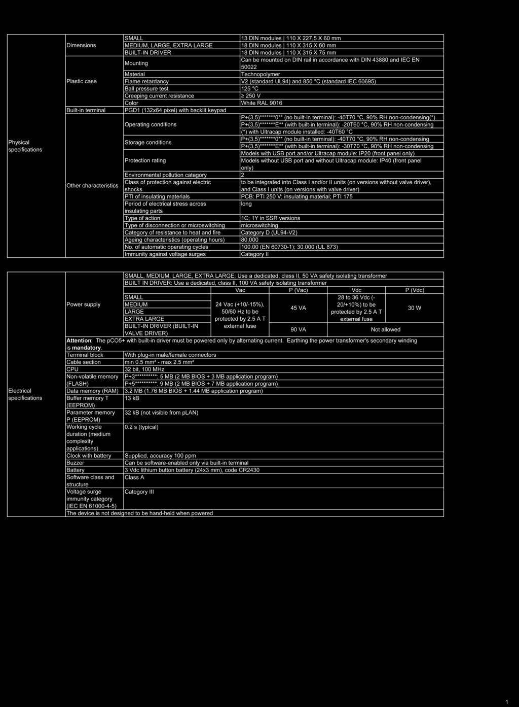
77 SPECIFICATIONS 77
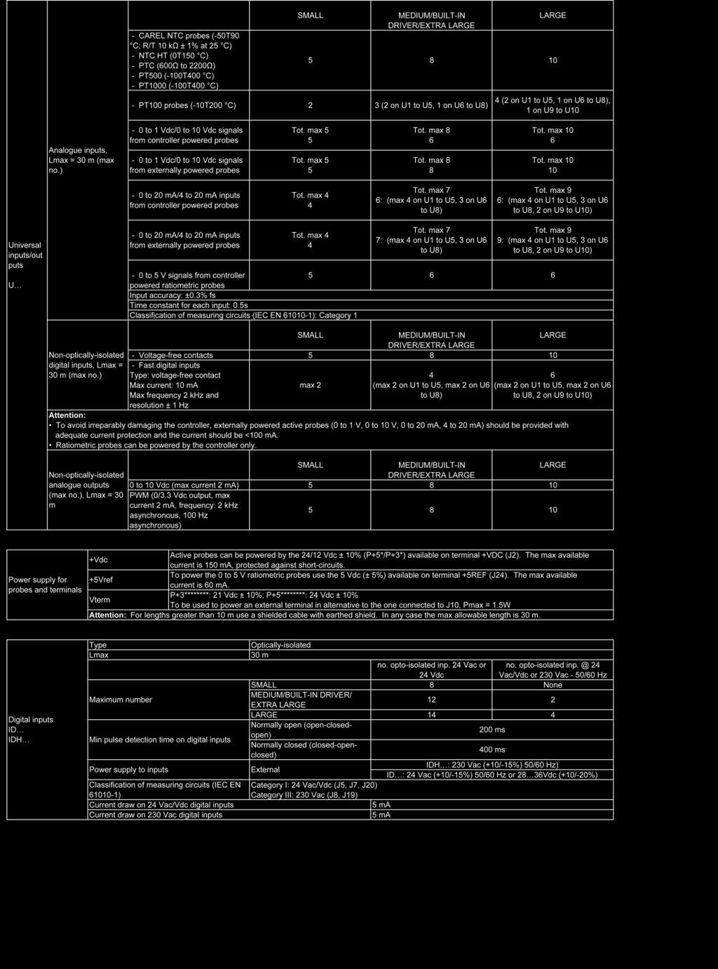
78 78
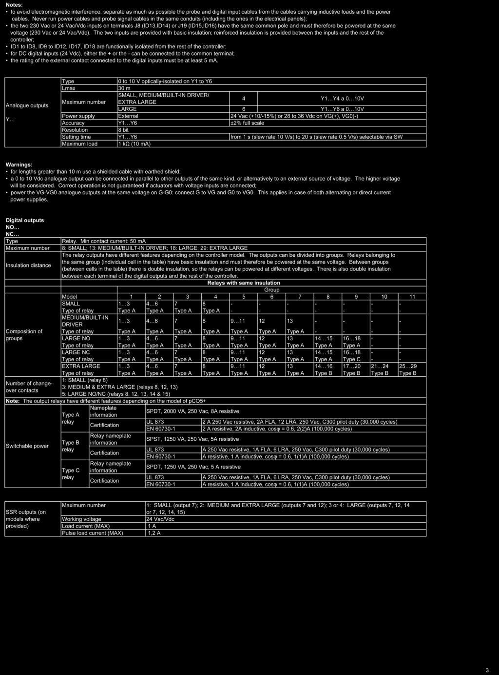
79 79
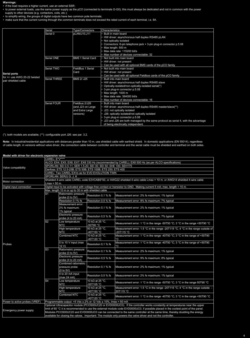
80 80
DOAS CM3500 Controller
 DOAS CM3500 Controller Table of Contents Dehumidification Equipment Standard Limited Warranty 3 Installation 4 IAQ Controller Details 7 Alarms 27 Hardware Details 30 Specifications 33 Points List 37 Revision
CM3500 Controller - ClimateMaster DOAS Water-Source Heat Pumps - Rev.: 7 Oct, 2008B
 2 CM3500 Controller - ClimateMaster DOAS Water-Source Heat Pumps - Rev.: 7 Oct, 2008B CAUTION CAUTION - ONLY TRAINED, QUALIFIED PERSONNEL SHOULD INSTALL AND/OR SERVICE CLIMATEMASTER EQUIPMENT. SERIOUS
TAP v2.10 Version Date: 6/12/13. Document Microprocessor Controller for Tempered Air Products
 Document 475595 Microprocessor Controller for Tempered Air Products Reference Guide for the Microprocessor Controller Please read and save these instructions. Read carefully before attempting to operate
Reference Guide for Microprocessor Controller
 Document 483232 Microprocessor Controller for Energy Recovery Reference Guide for Microprocessor Controller Please read and save these instructions for future reference. Read carefully before attempting
Reference Guide for Microprocessor Controller
 Document 483586 Microprocessor Controller for Dedicated Outdoor Air System Reference Guide for Microprocessor Controller Please read and save these instructions for future reference. Read carefully before
Reference Guide for Microprocessor Controller
 Document 482641 Microprocessor Controller for Make-Up Air Products Reference Guide for Microprocessor Controller Please read and save these instructions for future reference. Read carefully before attempting
DC 60 & DM 60 displays
 USER MANUAL DC 60 & DM 60 displays BALTIC FLEXAIR ENERGY AIRCOOLAIR COMPACTAIR FLATAIR (& Inverter) AQUALEAN DC60-DM60-IOM-1310-E www.lennoxemea.com Summaries 1 Display DC60 1.1 Introduction... 2 1.2
Marvel S MICROPROCESSOR CONTROLLER. Installation, Operation and Maintenance Manual Effective October 2018 DISCONTINUED. For Reference Only
 Marvel S MICROPROCESSOR CONTROLLER Installation, Operation and Maintenance Manual Effective October 2018 DISCONTINUED For Reference Only ***Interactive PDF*** Contents General Purpose...3 Standard And
DAP III Zone Master User s Guide
 DAP III Zone Master User s Guide Data Aire, Inc. 230 West BlueRidge Avenue Orange, California 92865 Document Number 600-000-788 March 2010 Revision 1.0 Document # 600-000-788 1 Overview The Data Aire DAP
Digital Precise Air Control - DPAC
 Digital Precise Air Control - DPAC Mode Enable Sensor Options The temperature of this sensor will determine if the unit is in heating, cooling or vent mode during Occupied operation. The following options
Refrigeration Controller Operator s Manual (HRC) PO Box 6183 Kennewick, WA
 PO Box 6183 Kennewick, WA") Refrigeration Controller Operator s Manual (HRC) PO Box 6183 Kennewick, WA 99336 www.jmcvr.com 1-509-586-9893 Table of Contents TABLE OF FIGURES...1 OVERVIEW OF THE HRC CAPABILITIES...2 INSTALLATION AND
Refrigeration Controller Operator s Manual (HRC) PO Box 6183 Kennewick, WA 99336 www.jmcvr.com 1-509-586-9893 Table of Contents TABLE OF FIGURES...1 OVERVIEW OF THE HRC CAPABILITIES...2 INSTALLATION AND
Installation Instructions / User s Manual TSTAT0406 and TSTAT0408
 997-060180-5 Installation Instructions / User s Manual TSTAT0406 and TSTAT0408 4 HEAT 2 COOL DUAL FUEL TSTAT0406 & TSTAT0408-4 WIRE CAPABLE THERMOSTAT (NAXA00201DB Daughter Board sold separately) LEFT
ModSync Sequencing System Installation & Operation Manual. For use with Fulton Steam Boilers.
 ModSync Sequencing System Installation & Operation Manual For use with Fulton Steam Boilers. Revision 3.0 8/21/2008 - 2 - Table of Contents Introduction Page 4 Features Page 4 Sequence of Operation Page
1 For All Programmable Digital Thermostat
 OWNER'S MANUAL P/N P374-2300FM 1 For All Programmable Digital Thermostat Am OFF OVERRIDE Meets California Title 24 unts flush to the wall 7 Day Programmable 3 Occupied, 1 Unoccupied Auto-Changeover Large,
User s Manual
 997-060180-4e User s Manual 8403-060 Menu Driven Display 1120-445 I. CONTROLLER OPERATION ADJUSTING TEMPERATURE (Temporary Override when in Programmable mode) 1. Before you can adjust the temperature,
VAV Thermostat Controller Specification and Installation Instructions. Model TRO24T4XYZ1
 Model TRO24T4XYZ1 Description The TRO24T4XYZ1 is a combination controller and thermostat. The VAV Thermostat Controller is designed for simple and accurate control of any variable air volume box in a number
INSTALLATION & OPERATION MANUAL
 INSTALLATION & OPERATION MANUAL Model TME- * * Balance of model number is determined by customer specifi ed limits and Setbacks. AUTOMATIC SETBACK THERMOSTAT LIGHT SENSING OR CONTACT CLOSURE FOR LOW VOLTAGE
INSTALLER S & OWNER S MANUAL
 INSTALLER S & OWNER S MANUAL HVAC INSTALLER: PLEASE LEAVE MANUAL FOR HOMEOWNER DEH 3000R Part No. 4028407 Dehumidifier & Ventilation System Controller 4201 Lien Road, Madison, WI 53704 TOLL-FREE (800)-533-7533
SA Series Start up Report
 SA Series Start up Report Important To ensure warranty validation and continued customer satisfaction, complete this form and return it to Desert Aire immediately after start-up. Validation of this report
SEQUENCE OF OPERATIONS
 SEQUENCE OF OPERATIONS DDC CONTROLLER: Controller with integral LCD readout for changing set points and monitoring unit operation. Provided with required sensors and programming. Factory programmed, mounted,
I/O ZONE 560/583 USERS GUIDE
 I/O ZONE 560/583 USERS GUIDE 641-224 641-242 641-237 1 Table of Contents Hot Gas Re-Heat Valve On/Off:... 15 THE ZONE CONTROLLER...4 Modulating Re-Heat Valve:... 16 SPECIFICATIONS...5 CONTROLLER COMPONENTS...6
GeneSys Air-Cooled Screw Compressor Chiller
 Operation Manual OM AGSB-5 Group: Chiller Part Number: 331373201 Date: June 2005 Supersedes: OM AGSB-4 GeneSys Air-Cooled Screw Compressor Chiller AGS 230A/B through AGS 475A/B, 60 Hertz AGS 206A/B through
Installation and Operation Manual for ER Units
 Installation and Operation Manual for ER Units Backlit LCD User Interface Programmed by Desert Aire for dehumidification and temperature control Alarm history retention Internal time clock for stand alone
INSTALLER S & OWNER S MANUAL
 INSTALLER S & OWNER S MANUAL HVAC INSTALLER: PLEASE LEAVE MANUAL FOR HOMEOWNER Part No. 4028539 Dehumidifier & Ventilation System Controller 4201 Lien Rd Madison, WI 53704 TOLL-FREE 1-800-533-7533 www.thermastor.com
Installation, Start-Up, and Operating Instructions
 Installation, Start-Up, and Operating Instructions IMPORTANT: Read entire instructions before starting the installation. SAFETY CONSIDERATIONS Read and follow manufacturer instructions carefully. Follow
Dryer Controller M720
 User Manual Dryer Controller M720 Hardware version 2.00 Software version 2.00 Manual M720 Dryer controller Page 1 of 60 Document history Preliminary version: - Created in April, 2009 Hardware Version 2.00,
User s Manual. TIGER S EYE E-Series Mark V Jockey. TIGERFLOW Systems, Inc Mint Way Dallas, Texas
 User s Manual TIGER S EYE E-Series Mark V Jockey TIGERFLOW Systems, Inc. 4034 Mint Way Dallas, Texas 75237 214-337-8780 www.tigerflow.com TABLE OF CONTENTS Introduction... 4 Sequence of Operation... 5
Digital Programmable
 www.geappliances.com Digital Programmable Thermostats Operating Instructions Auto Changeover..........10 Day/Time Setting Mode.....6 Default Mode...............4 Fan Control...............10 Hold and Temporary
1.0 Digital Controller
 1.0 Digital Controller...1 1.1 Display Function Keys...1 1.2 Thermostat Display...2 1.3 Controller hardware input output points... 4 2.0 Sequence of Operation...5 2.1 States of Operation...5 2.2 Modes
Product Manual SZ1009
 Product Manual SZ1009 Conventional Heating & Cooling Thermostats with Heat Pump Mode Communicating Thermostats Description The SZ1009 is a microprocessor-based mable thermostats designed for conventional
Fan Coil Thermostat Controller Specification and Installation Instructions. Model TFHB24F3XYZ1 with External Humidity Sensor and BACnet Communication
 Model TFHB24F3XYZ1 with External Humidity Sensor and BACnet Communication Description The TFHB24F3XYZ1 is a fully configurable controller designed specifically for 2 pipe and 4 pipe fan coil applications.
Marvel J MICROPROCESSOR CONTROLLER
 Marvel J MICROPROCESSOR CONTROLLER Installation, Operation and Maintenance Manual Effective August 2016 ***Interactive PDF*** Contents General Purpose... 3 Standard Components... 3 Number of I/O Allowable...
MARVEL PREMIUM HVAC MICROPROCESSOR CONTROLLER
 MARVEL PREMIUM HVAC MICROPROCESSOR CONTROLLER Installation, Operation and Maintenance Manual Effective May 2017 ***Interactive PDF*** CONTENTS GENERAL PURPOSE 3 MARVEL PREMIUM - CONTROLLABLE SYSTEM COMPONENT
User Manual. Dryer Controller M720
 User Manual Dryer Controller M720 Hardware version 1.00 Software version 1.00 Preliminary version Manual M720 Dryer controller Page 1 of 42 Document history Preliminary version: - Created in April, 2009
Custom Control Systems Inc. Ellis Dryer Control Configuration and Operation Manual
 Ellis Dryer Control Configuration and Operation Manual Revised 1/19/2004 Table of Contents 1 Introduction... 7 1.1 Hardware Specifications... 7 1.2 Software Features... 7 1.3 Warranty... 8 1.3.1 Terms...
5+2 DAY. OWNER S MANUAL Venstar Inc. 05/08
 Digital Thermostat residential THERMOSTAT 5+2 DAY PROGRAMMABLE up to 1-heat & 1-cool PUMP Stages: 1-Heat, 1-Cool Battery or System Powered Back-Lit Digital Display Fahrenheit or Celsius Service Filter
OPERATING MANUAL Enertronic Control System 2
 OPERATING MANUAL Enertronic Control System 2 The integrated control system for Lennox chillers in the Ecologic range Manufacturer: Lennox Benelux B.V. Postbus 1028, 3860 BA NIJKERK Watergoorweg 87, 3861
CONTROLS MANUAL For all Innovent and Valent air handling products
 CONTROLS MANUAL For all Innovent and Valent air handling products TABLE OF CONTENTS TABLE OF CONTENTS IMPORTANT INFORMATION Safety information...................................................................................
*IG1583EW* Aurora Touch UPC Kit Instruction Guide. Aurora Touch UPC Kit Instruction Guide
 Aurora Touch UPC Kit Instruction Guide For use in single compressor water-to-air equipment utilizing fi rmware UPCSWASTD01-01 Aurora Touch UPC Kit Instruction Guide *IG1583EW* IG1583EW 08/14 Aurora Touch
Owner s Manual. Part Number 33CSSP2-FC BACK LIT LIQUID CRYSTAL DISPLAY MODE BUTTON
 Owner s Manual Part Number 33CSSP2-FC 33CS Fan Coil Programmable Thermostat SAFETY CONSIDERATIONS Read and follow manufacturer instructions carefully. Follow all local electrical codes during installation.
SC Installation, Operation & Application Guide
 SC 5211 2-Stage Heat Pump Auto Changeover Hardwire Programmable Electronic Thermostat 7-Day, 5-2-Day or 5-1-1-Day Programmable Configurable 2-Stage Heat Pump Systems Large Display With Backlight Selectable
1.0 Digital Controller
 Form CP-AHU D19_D21_D22 (11-17) D303072-A Obsoletes Forms CP-Preeva-D21 (1-16) Doc No 303072, CP-Preeva-D19 (1-16) Doc No 303071 Applies to: Preeva, MAPS, MAPS II, RPB, RPBL & SSCBL Series For Air Handler
Fan Coil Thermostat Controller Specification and Installation Instructions. Model TFH24F3XYZ2 Stand-alone with Internal Humidity Sensor
 Model TFH24FXYZ2 Stand-alone with Internal Humidity Sensor Description The TFH24FXYZ2 is a fully configurable controller designed specifically for 2 pipe and 4 pipe fan coil applications. No additional
Modular Standard HP Chiller 1/4 screw compressor with Carel driver
 Program for pco¹ pco 2 and pcoc Modular Standard HP Chiller 1/4 screw compressor with Carel driver Manual version 1.0 25 September 2003 Program code: FLSTDmMSDE Do we want you to save you time and money?
Siemens Thermostats. RDY2000BN Thermostat
 Siemens Thermostats RDY2000BN Thermostat Answers for infrastructure and cities. Introducing the RDY2000BN BACnet Commercial Thermostat Bring more buildings and zones under control Reduce energy costs BACnet
Owner s Manual. Digital. Heat Pump. 5+2 Day Programmable. Model S1-THEH21P5S HVAC SERVICE PARTS TM
 Owner s Manual Model S1-THEH21P5S HVAC SERVICE PARTS TM Heat Pump 5+2 Programmable Digital T h e rm ostats t a t BACKLIT DISPLAY Use with most Heat Pump systems: 1-Heat, 1-Cool 2-Heat, 1-Cool Control up
CONTROL OPTIONS SPACE HEATING APPLICATIONS MAKEUP AIR HEATING APPLICATIONS PEH, PXH, RDH, REH, RXH, SDH & SHH. Horizontal Split System- Models PDH,
 SPACE HEATING APPLICATIONS MAKEUP AIR HEATING APPLICATIONS Options AG3 Unit-Mounted Ductstat Options AG15, AG16 A = Ductstat Temperature Module P/N 115848 B = Stage Adder Module, P/N 115849 (quantity varies
REMOTE CONTROL FOR CHILLER MYCHILLER
 REMOTE CONTROL FOR CHILLER MYCHILLER GENERAL FEATURES... 3 MAIN FUNCTIONS AND EQUIPMENT:... 3 LCD DISPLAY... 4 KEYBOARD... 5 BOARD CONFIGURATION... 7 LIST OF MAIN PARAMETERS... 7 CONFIGURATION OF MAIN
7-Day. Digital Thermostat. residential. & 2-cool
 Digital Thermostat residential THERMOSTAT T1100FS 7-Day PROGRAMMABLE up to 2-heat & 2-cool PUMP Control up to 2 Heat & 2 Cool Stages 7-Day Programmable 4 Settings/Day Auto Changeover 5 minute Built-In
ATC32U03 igate Communicating, Programmable Thermostat
 ATC32U03 igate Communicating, Programmable Thermostat User Manual 97B0055N02 Rev.: 11/3/17 Table of Contents Section Title Page Menu Navigation Shortcuts 3 1.0 Operating Mode Selection 3 2.0 Temperature
Owner s Manual. Part Number 33CS250-01
 33CS Commercial Programmable Thermostat IMPORTANT: Read entire instructions before programming the thermostat. Owner s Manual Part Number 33CS250-01 GENERAL Carrier s 7-day, commercial, programmable thermostats
OWNER S MANUAL. Part Number P
 OWNER S MANUAL CPV230 Commercial Thermostat Part Number P374-2300 CONTENTS Page GENERAL...2 CONFIGURATION...3-12 Thermostat Display...3 Heat or Cool Indicator...4 Thermostat Front Panel Buttons...4 Thermostat
Owner s Manual. Part Number 33CS250-FS and 33CS220-FS
 Debonair 33CS Flush-Mounted Flatstat Commercial Programmable Thermostat IMPORTANT: Read entire instructions before programming the thermostat. Owner s Manual Part Number 33CS250-FS and 33CS220-FS GENERAL
OWNER S MANUAL Venstar Inc. 08/07
 Digital Thermostat commercial SCHOOL THERMOSTAT T2900SCH MABLE up to 3-heat & 2-cool HEAT COOL HEAT PUMP Energy Saving Operation Morning Warm-up Period Programmable Override Unoccupied until button press
C-TRAC3 COMMUNICATION MANUAL FOR. BACnet NOVEMBER 2010 TO JANUARY 2014 USA HEAD OFFICE AND FACTORY
 A C-TRAC3 COMMUNICATION MANUAL FOR BACnet NOVEMBER 2010 TO JANUARY 2014 UNIT MODEL NO. UNIT SERIAL NO. SERVICED BY: TEL. NO: CANADIAN HEAD OFFICE AND FACTORY 1401 HASTINGS CRES. SE CALGARY, ALBERTA T2G
HEAT COOL. Meets Commercial California Title 24
 Digital Thermostat commercial THERMOSTAT T2900 7-DAY MABLE up to 3-heat & 2-cool HEAT COOL HEAT PUMP Control up to 3 Heat & 2 Cool Stages 3 Configurable Outputs Adjustable 2nd & 3rd Stage Timers & Deadbands
Thermostats. Digital Programmable. GEAppliances.com
 GEAppliances.com Digital Programmable Thermostats Owner s Manual & Installation Instructions RAK148P2 RAK164P2 Configuration Mode...8 9 Important Safety Information... 2 Installation Instructions... 4
VENSTAR T1075 FAN COIL THERMOSTAT 7 DAY PROGRAMMABLE 2 OR 4 PIPE SYSTEMS OWNER S MANUAL AND INSTALLATION INSTRUCTIONS
 VENSTAR FAN COIL THERMOSTAT FAN COIL THERMOSTAT T1075 7 DAY PROGRAMMABLE 2 OR 4 PIPE SYSTEMS 3 Occupied, 1 Unoccupied Override capable 3 speed fan control Auto 2-pipe changeover when used with accessory
Installer Guide. WARNING Important Safety Information. 1 Specifications
 1 Specifications cont. Premier Series Universal Auto Changeover Up to 3 Heat / 2 Cool Conventional and Heat Pump Thermostat Installer Guide Before Installing, Programming or Operating, PLEASE READ ALL
SECTION SEQUENCE OF OPERATIONS FOR HVAC CONTROLS
 PART 1 - GENERAL SECTION 23 09 93 SEQUENCE OF OPERATIONS FOR HVAC CONTROLS 1.1 SUMMARY A. This Section includes control sequences for HVAC systems, subsystems, and other equipment. B. See Division 23 Section
ATC32U01 igate Communicating, Programmable Thermostat
 ATC32U01 igate Communicating, Programmable Thermostat User Manual 97B0055N02 Rev.: 7/2/12 Table of Contents Section Title Page Menu Navigation Shortcuts 3 1.0 Operating Mode Selection 3 2.0 Temperature
AdaptAire. Digital Control System. User Manual. Expert Systems
 AdaptAire Digital Control System User Manual Expert Systems Rev. 10-29-15 1 2 Table of Contents OVERVIEW... 8 NETWORKING... 10 ADAPTAIRE DEFAULT SETTINGS... 10 UNIT OPERATING MODES... 11 MRT Controls:...
For Quick Set-Up go to Page 14
 Talking Thermostat Model VT3000 Guide SmartWay Solutions, Inc. US Patent 6,608,560 & 7,62,253 For Quick Set-Up go to Page 4 Model VT3000, a universal thermostat for use on most Gas or Electric, Conventional
T60xDFH-4 and T60xDFH-4+PIR Series Thermostat Controllers with Dehumidification and Occupancy Sensing Capability
 T60xDFH-4 and T60xDFH-4+PIR Series Thermostat Controllers with Dehumidification and Occupancy Sensing Capability Product Bulletin T601DFH-4, T602DFH-4, T603DFH-4, T604DFH-4, T605DFH-4, T601DFH-4+PIR, T602DFH-4+PIR,
Owner s Manual. Digital Thermostat. Heat/Cool & Heat Pump 7-Day Programmable S1-THEM22P7S COMMERCIAL. Model HVAC SERVICE PARTS
 Owner s Manual Model COMMERCIAL TM BACKLIT DISPLAY HVAC SERVICE PARTS Heat/Cool & Heat Pump 7-Day Programmable Digital Thermostat Use with most Heat Pump Systems: 2-Heat, 2-Cool Stages: 2-Heat, 2-Cool
TEC2620 Series Non-Programmable Fan Coil Network Thermostat Controller and Remote I/O Relay Packs
 TEC2620 Series Non-Programmable Fan Coil Network Thermostat ler and Remote I/O Relay Packs TEC2620H-0, TEC2620C-0, TEC2620H-0+PIR, TEC2620C-0+PIR, TEC2621H-0, TEC2621C-0, TEC2621H-0+PIR, TEC2621C-0+PIR
Tri-Stack Smart System
 Tri-Stack Smart System TM Notes & Warnings - The protection provided by this equipment may be impaired if it is not used in the manner specified herein. - Ensure all wiring meets applicable national and
HEAT HEAT HEAT COOL COOL PUMP OWNER S MANUAL 7-DAY TOTALINE
 OWNER S MANUAL COMMERCIAL THERMOSTAT P/N P374-2800 I 2 : 0 0 Su AUTO Pm 74 COOL 7 2 HEAT T O T A L I N E HEAT COOL 7-DAY HEAT PUMP PROGRAMMABLE DIGITAL THERMOSTAT 3 Configurable Outputs Control up to 2
Safety & Installation Instructions
 Model 8800 Universal Communicating Thermostat Safety & Installation Instructions READ AND SAVE THESE INSTRUCTIONS Table of contents Installation Installation location recommendations... 2 Thermostat mounting...
VENSTAR T1070 FAN COIL THERMOSTAT PROGRAMMABLE 2 OR 4 PIPE SYSTEMS OWNER S MANUAL AND INSTALLATION INSTRUCTIONS
 VENSTAR FAN COIL THERMOSTAT FAN COIL THERMOSTAT T1070 NON- PROGRAMMABLE 2 OR 4 PIPE SYSTEMS Remote sensor ready 3 speed fan control Self-prompting adjustment Auto 2-pipe changeover when used with ACC-SENFC
MicroTech Series-200 Flooded Screw Chiller
 Open Protocol Data Infomation Packet Version 1.0 Group: Controls Date: February 1997 MicroTech Series-200 Flooded Screw Chiller Open Protocol Data Communications 2002 McQuay International - C O N F I D
SEQUENCE OF OPERATION FOR ALC CONTROL AIR SOURCE HEATPUMP RECIRCULATION AIR WITH ECONOMIZER
 SEQUENCE OF OPERATION FOR ALC CONTROL AIR SOURCE HEATPUMP RECIRCULATION AIR WITH ECONOMIZER Printed in the USA ADSOOASHPRAE 0117 Orig SEQUENCE OF OPERATION The ALC controller is turned on by a switch located
SC Installation, Operation & Application Guide
 SC 3006 Auto Changeover 7-Day Programmable Hardwired Programmable Electronic Thermostat 7-Day Programmable Single Stage Heat Pump/Non-Heat Pump Systems Backlit Display Single Stage Heat/Cool Systems Field
Mark 25 Ultrapure Water Conductivity Analyzer
 Martek Instruments, Inc. Mark 25 Ultrapure Water Conductivity Analyzer Instruction Manual WARRANTY POLICY Unless otherwise stated, MARTEK INSTRUMENTS, INC. warrants this equipment to be free from defects
RSMSD Technical Guide
 RSMSD Technical Guide www.aaon.com AAON/WattMaster Controls Inc. 8500 NW River Park Drive Parkville, MO 64152 Toll Free Phone: 866-918-1100 PH: (816) 505-1100 FAX: (816) 505-1101 E-mail: mail@wattmaster.com
RPM1600 Series Room Pressure Monitors
 RPM1600 Series Room Pressure Monitors Technical Bulletin LB-RPM1611-0, LB--0 Code No. LIT-12012228 Issued October 2017 Refer to the QuickLIT website for the most up-to-date version of this document. How
WIRING DIAGRAMS R410A MODELS PAC 2OAC/2OACH CAC OWC PWC
 WIRING DIAGRAMS R410A MODELS 2OAC/2OACH PAC CAC PWC OWC WIRING 02172017 TABLE OF CONTENTS PAGE 2OACH Deluxe Portable Air-cooled Heat Pump Electronic Controller... 2-3 Piping Schematic... 4 Single Phase
OPERATING MANUAL Enertronic Control System 2
 OPERATING MANUAL Enertronic Control System 2 The integrated control system for Lennox chillers in the Ecologic and Seconscrew ranges Manufacturer Lennox Benelux B.V. Postbus 1028, 3860 BA NIJKERK Watergoorweg
Product Manual SZ1022/SZ1031/SZ1035/
 Product Manual SZ1022/SZ1031/SZ1035/ Conventional Heating & Cooling Thermostats Communicating Thermostats Description The SZ1022, SZ1031, and SZ1035, are microprocessorbased mable thermostats designed
SC Installation, Operation & Application Guide
 SC 5811 2 Heat/2 Cool Auto Changeover Hardwire Programmable Electronic Thermostat 7-Day, 5-2-Day or 5-1-1-Day Programmable Configurable 2-Stage Heat/2-Stage Cool Systems 2-Stage Heat Pump Systems Large
Rooftop Thermostat Controller Specification and Installation Instructions. Model TRT2422
 ºF / º C Rooftop Thermostat Controller Model TRT2422 Description The TRT2422 is a combination controller and thermostat with a built-in scheduler, which is designed for simple and accurate control of single
T600MEP-2 Programmable Economizer Thermostat
 Installation Instructions Issue Date January 19, 2005 T600MEP-2 Programmable Economizer Thermostat Application The T600MEP-2 is a programmable thermostat for control of single- or two-stage unitary rooftop
MARVEL MINI HVAC MICROPROCESSOR CONTROLLER
 MARVEL MINI HVAC MICROPROCESSOR CONTROLLER Installation, Operation and Maintenance Manual Effective January 2019 ***Interactive PDF*** CONTENTS GENERAL PURPOSE 3 - Controllable System Component Information
Installation and Operations Manual
 Installation and Operations Manual H-IM-LLC February 2018 Part No. 25092501 Replaces H-IM-LLC (01/2014) Lead Lag Control System Table of Contents General Safety Information 2 Inspection 2 Warranty Statement
SECTION SEQUENCE OF OPERATIONS FOR HVAC CONTROLS
 SECTION 23 09 93 SEQUENCE OF OPERATIONS FOR HVAC CONTROLS PART 1 - GENERAL 1.1 SUMMARY A. This Section includes control sequences for HVAC systems, subsystems, and equipment. B. See Division 23 Section
MARVEL MINI HVAC MICROPROCESSOR CONTROLLER
 MARVEL MINI HVAC MICROPROCESSOR CONTROLLER Installation, Operation and Maintenance Manual Effective December 2018 Building Management System ***Interactive PDF*** CONTENTS GENERAL PURPOSE 3 - Controllable
Water Source Heat Pump Module Technical Guide
 Factory Packaged Controls Tulsa Water Source Heat Pump Module WSHP WSHP Protection Module Module Orion No.: OE334-23-WPM-A NON-DIGITAL COMPRESSORS #1 THRU #4 +5V SUCT. +5V SUCTION PR. SENSOR PRES PRES
EMERSON BLUE Wireless Comfor t Inter face 1F98EZ-1621 HOMEOWNER USER GUIDE
 EMERSON BLUE Wireless Comfor t Inter face 1F98EZ-1621 HOMEOWNER USER GUIDE Emerson Blue Wireless Comfort Interface - Homeowner User Guide Message to Homeowners Congratulations on choosing the Emerson Blue
 ZIP Economizer Method of Operation Sequence of Operation States Virgin State The ZIP Economizer comes shipped from the factory in this state. Setup Incomplete will be displayed. No control will occur until
User s Manual. THE iq Drive SYSTEM USER S INFORMATION IMPORTANT. Variable Speed Ultra-High SEER Split System IMPORTANT NOTE
 User s Manual Variable Speed Ultra-High SEER Split System These units have been designed and tested for capacity and effi ciency in accordance with ARI standards. These outdoor air conditioning units are
Pioneer Gold Controller Technical Guide
 Pioneer Gold Controller Technical Guide Pioneer Gold Controller Code: Version 1.03 Electric Heat Expansion Module Code: Version 1.0 Used with AAON WSHP WV Series Vertical and WH Series Horizontal This
Your Home. Jacco & Assoc.
 Your Home Fan on with call for heating or cooling Heating on with call from space thermostat Stage as required to maintain The 75F Basics adj. - First stage of heating shall be heat pump Cooling on with
Pioneer Gold Controller Technical Guide. Pioneer Gold Controller Code: Version 1.1 Used with AAON WSHP WV Series Vertical and WH Series Horizontal
 Pioneer Gold Controller Technical Guide Pioneer Gold Controller Code: Version 1.1 Used with AAON WSHP WV Series Vertical and WH Series Horizontal WARNING QUALIFIED INSTALLER IMPROPER INSTALLATION, ADJUSTMENT,
HIGH EFFICIENCY FIRETUBE CONDENSING GAS BOILER
 This manual must be left with owner and should be hung on or adjacent to the boiler for reference. US HIGH EFFICIENCY FIRETUBE CONDENSING GAS BOILER MODELS CHS-85 through CHS-399 APPENDIX A CONTROLLER
AdaptAire. Digital Control System. User Manual
 AdaptAire Digital Control System User Manual Rev. 10-22-07 1 Table of Contents OVERVIEW... 6 NETWORKING... 7 ADAPTAIRE DEFAULT SETTINGS... 7 UNIT OPERATING MODES... 8 MDT Controls:... 8 UNIT OFF MODE...8
CommStat 6. Controller for Redundant HVAC Systems PRODUCT DATA SHEET
 CommStat 6 Controller for Redundant HVAC Systems PRODUCT DATA SHEET General Description The CommStat 6 HVAC controller is designed for controlling up to six redundant air conditioners in an E-House or
Pump-Down Controller MODEL 4052
 Pump-Down Controller 4-20mA Input/Scalable Output Seal Fail Monitoring Duplex Pump Alternation Hand-Off-Auto Controls Dual Run-time Meters RS-485/Modbus Communications DESCRIPTION The Model 4052 Pump-Down
Owner s Manual. Digital Thermostat
 Model Air Conditioning & Heating Heat Pump 5+2 Day Programmable Digital Thermostat Control up to 2-Heat & 1-Cool Battery or System Powered Backlit Digital Display Auxiliary Heat Indicator Fahrenheit or
HEAT HEAT HEAT COOL COOL
 OWNER S MANUAL AUTO 74 COOL 7 2 HEAT T O T A L I N E HEAT COOL COMMERCIAL THERMOSTAT P/N P374-2700 HEAT PUMP NON-PROGRAMMABLE DIGITAL THERMOSTAT 3 Configurable Outputs Control up to 2 Heat & 2 Cool Stages
A-Tech-20 Advanced Microprocessor Controller
 A-Tech-20 Controller Operation Manual (04/02/01) 1 C Y B E R A i R Product Division A-Tech-20 Advanced Microprocessor Controller Operations Manual Project: SATS Model: SATS SN: SATS JN: Unit Tags: REVISION