Design Options For HVAC Distribution System. Course Content
|
|
|
- Kristina Greene
- 6 years ago
- Views:
Transcription
1 Design Options For HVAC Distribution System Course Content CENTRAL HVAC SYSTEM AN OVERVIEW The objective of an HVAC (heating, ventilating, and air-conditioning) system is to control the temperature, humidity, air movement and air cleanliness, normally with mechanical means, to achieve thermal comfort. Centralized HVAC system installation utilizes number of separate components that are field assembled to serve the specific needs of an individual building. A central plant has 4 principle elements: 1. Energy Supply (e.g. electricity, fuel) 2. Service Generators (e.g. boilers, chillers) 3. Distribution Components (e.g. air distribution ducts, pipes) 4. Delivery Components (e.g. diffusers, radiators) Distribution components convey a heating or cooling medium from source location service generators to portions of a building that require conditioning. Delivery components serve as an interface between the distribution system and occupied spaces. In this course we shall focus on the various design options pertaining to cooling and heating air distribution (item no. 3 & 4). (For item 1 & 2, HVAC generating services refer to separate courses viz. Selection tips for cooling systems and HVAC made easy-chiller compressors ) HVAC systems are of great importance to architectural design efforts for three main reasons. 1. First, these systems consume substantial floor space and/or building volume for equipment and distribution elements that must be accommodated during the design process. 2. Second, HVAC systems constitute a single major budget item in building projects Page 1 of 58
2 3. Third, the success of building depends on the ability to provide thermal comfort with least operating costs (maintenance, energy, or replacement) which in turn depends on the HVAC system design, equipment and controls There are several choices for air distribution, each satisfying the HVAC objectives with different degrees of success. The best design shall consider the pertinent architectural and financial constraints without sacrificing the performance in terms of reliability, indoor air quality and energy efficiency. While HVAC system design is a responsibility of HVAC designer, an architect has to oversee the complete building project on a wider perspective. The type of system selected is determined by HVAC designer's knowledge of systems. Architect must also understand the basics, system objectives, the role of key system components, the type of systems that are available and what such systems can and cannot accomplish. In selecting a suitable air conditioning system for a particular application, considerations are given to the following: - 1. Architectural Constraints: Details of architecture and building construction Floor space and clear heights to accommodate HVAC equipment and distribution elements Aesthetics Size and appearance of terminal devices Coordinating reflected ceiling plans with lighting, fire sprinklers/detectors Acceptable noise level Space available to house equipment and its location relative to the conditioned space Shaft spaces available for routing ducts/pipes etc Climate and shading Indoor & outdoor equipment preferences Acceptability of components obtruding into the conditioned space Codes & standards, smoke removal systems Usage patterns Occupancy 2. System constraints: Type of facility/indoor conditions required Cooling/heating load Page 2 of 58
3 Zoning requirements Humidification/dehumidification need Energy availability & efficiency Redundancy and equipment configuration Type of Equipment Reliability of operations Control scheme Zone/individual control 3. Financial Constraints Capital cost Operating cost Maintenance cost Replacement costs Upgrading costs Equipment failure costs Return of investment (ROI)/Life cycle analysis Depending on the customer s goals each of these concerns has different priority. Most customers may not understand HVAC design aspects; their benefits and limitations and it is the architect s and HVAC engineer's responsibility to guide and advise the best option. For HVAC engineer the customer may be an architect whose customer may be the building owner. HVAC DISTRIBUTION SYSTEMS Central cooling and heating system can be designed/distributed using several different modes. Centralized systems All Air systems (significant ducting) Air-Water systems (moderate ducting) All Water systems (ductless systems) Refrigerant (usually for smaller applications) Terminal units Page 3 of 58
4 Fan-coils Inductors Radiators Diffusers Individual (unitary air-conditioning) systems Compact Split Heat pumps Within above, there are lot many variants. A building may use the hybrid combination of these to best satisfy the overall functional objectives. There are many options but most conventional centralized systems fall under one of three categories, All Air System, All Water System, or Air-Water System. All Air Systems deliver heated/cooled air to each space through ducts All Water Systems deliver chilled/hot water to each space and rely on indoor terminal units Air-Water Systems deliver combination of heated/cooled air and hot/chilled water to control aspects of comfort. The obvious difference between the above three systems is the fluid that is used to heat/cool a space: air for all-air, water for all-water, and air and water for air-water. What causes so many variations in system design? The air-conditioning system may have several requirements that have to be accommodated in the design process: 1. The cooling, heating and moisture control provides the foundation for key HVAC system design/components. 2. The additional functions of air circulation and air quality control establish further component requirements. 3. In specific building situations, supplemental functions such as noise control to low decibels, interlocking with security & fire protection functions, smoke control etc. may be imposed on an HVAC system Page 4 of 58
5 4. Automation and control of an HVAC system is critical to its successful operation. The issue of system control leads to the concept of HVAC zoning. During the design process, a zone is defined as a region of a building that requires separate control if comfort is to be provided for occupants. Many different air distribution systems from unizone systems (the indoor space constitutes a unique conditioned zone) to multizone systems (different specifically conditioned indoor spaces) with or without reheat design options are available. 5. The air-conditioning system has to meet both the humidity and temperature requirements. Humidity control generally takes precedence over temperature control and as such the air is cooled much lower (equal to apparatus dewpoint of coil) to remove moisture over the coil surface. The resultant air becomes too cold which is reheated before it is dumped to the indoor spaces. The modern HVAC design relies on energy efficient variable air volume (VAV) systems and variable air volume and temperature (VVT) systems. Many other options are highlighted in the course. Page 5 of 58
6 PART 1 ALL AIR SYSTEMS All-Air central systems provide heated or cooled air to the space through ductwork. The system is categorized by a use of air-handling units (AHU) or roof top packages (RTP) to condition air and sends it through ductwork to the occupied space where the conditioned air will heat or cool the space as required and return via return air ducts back to the AHU or RTP. All air systems are applicable to various types of air-conditioning systems for comfort or process work. Air Handling Units contain a cooling coil (connected to a chiller or condensing unit) a heating coil (connected to boilers or electric heaters) filters and circulating fan(s). Roof Top Packages contain refrigerant cooling cycle, heating coils (connected to boilers or electric heaters), filters and circulating fan(s). Schematic arrangement of All-Air system with major components is highlighted below. OUTSIDE AIR AIR HANDLING UNIT - + SUPPLY DUCT SUPPLY TO OTHER ZONES RETURN AIR ZONE EXHAUST AIR RETURN DUCT RETURN AIR FAN (OPTIONAL) RETURN FROM OTHER ZONES All-air systems require that the majority of air supplied to a space is returned to the air-handling unit for reconditioning or exhausted from the building. This "return" air may be conveyed in a return air duct system or through plenums formed by various elements of a building, such as a suspended ceiling and the building structure. All-Air system is classified as 3 main categories: Single zone Dual or double duct Multi zone The systems could be further categorized as Constant Volume Systems with reheat Page 6 of 58
7 Variable Air Volume Systems with or without reheat Combination systems Why All-Air central system? The arrangement provides uniform air distribution through network of ducts and is most suitable to cover the large areas irrespective of width, length or depth of coverage. The central plant is located in unoccupied areas which consolidates operation and maintenance remotely and permits optimum choice of filtration systems, odor and noise attenuation. The system ensures complete absence of piping, electrical equipment, power wiring and filters in the indoor conditioned space The system is adaptable to automatic seasonal changeover and to winter humidification Systems can include energy conservation options such as airside economizer and heat recovery devices. During favorable ambient conditions say during night, outside air can be conveniently utilized in place of mechanical refrigeration. Provides a wide choice of zoning and humidity control under all operating conditions. Good choice where close zone temperature and humidity control is required. Provides good design flexibility for optimum air distribution, draft control, and local requirements Easily adaptable to fire and smoke removal system during emergency fire conditions Suited for applications requiring unusual exhaust makeup Allows simultaneous cooling and heating in various zones to maintain precise zone temperature and humidity conditions Some of the All-Air central system's drawbacks: 1. Significant space almost 10 to 15% depending on the economy of scale may be needed for AHU room/duct risers. 2. Requires additional duct clearances, which may add to building height and vertical airshafts can reduce the usable floor space. 3. Air balancing is difficult to achieve particularly in large systems and requires great care. 4. The logic control of achieving optimum conditions requires expert design planning and experience. There are various options among all-air systems and to ensure right selection requires a foresight of control logics and sequence. 5. May encounter hot or cold spots particularly in the perimeter zones having large glazing. Page 7 of 58
8 6. Installation and accessibility of equipment demands close cooperation between architectural, mechanical and structural engineers. 7. Airflow balancing is difficult. The reheat control option with all-air system is very energy inefficient as it requires first overcooling and than reheating for effective humidity control. ALL-AIR SINGLE DUCT AIR SYSTEMS The simplest and most common of All-Air central system is a single duct, single zone system. Single path systems contain the main heating and cooling coils in a series flow air path using a common duct distribution system that feeds all terminal apparatus. Single path systems may be sub-divided as!"single duct constant volume!"single duct VAV!"Single duct reheat A single zone system consists of an air-handling unit, a heat source and cooling source, distribution ductwork, and appropriate delivery devices. Figure below is a general arrangement of a single zone HVAC system. Control Philosophy In a single zone all-air HVAC system, one control device (most commonly a thermostat) located in the zone, controls the operation of the system. Control may be either modulating or on-off in nature. Page 8 of 58
9 A modulating control adjusts system output in increments to match heating or cooling loads. Modulating control may be achieved by varying the flow of hot or chilled water to a coil. On-off control is all-or-nothing, it simply starts and stops the heating or cooling effect; air circulation may also start and stop along with heating/cooling or may be set for continuous operation. As this type system serves only one zone, control is normally affected at the air-handling unit (AHU) through a change in supply air temperature or the stopping/starting of the system. The all-air single-zone air conditioning system is the basic central system, which can supply a constant air volume or a variable air volume at low, medium or high pressure. Normally, the equipment (air-handling unit) is located outside the conditioned space but can also be installed within the conditioned areas if conditions permit. In true sense very few buildings fall under a single thermal zone. Single zone systems find many applications because of simplicity. Most central HVAC systems serving one-family residential units are single zone systems. In larger residences, two (or more) single zone systems may be used to provide thermal zoning. In low-rise apartments, each apartment unit may be conditioned by a separate single zone system. Many large single-story buildings -- supermarkets, discount stores, and the like -- can be effectively conditioned by a series of single zone systems, each system serving a loosely defined region of the building. The central (or interior) zones of large office buildings are usually conditioned by single or series of separate single zone systems. Typical applications include: - 1. Space with uniform loads 2. Small spaces requiring precision control 3. Multiple single zone systems for large areas Advantages: 1. The primary advantage of a single zone central system is its simplicity of design 2. Single zone systems are the most basic and least complex of central all-air systems. 3. Low first cost among all other types 4. Easiest to maintain Disadvantages 1. It can effectively condition only one zone. This is only a disadvantage when improperly applied. Page 9 of 58
10 2. As control is achieved at the air-handling unit, single zone systems are not easily modified to serve multiple zones should building usage change with time. ALL-AIR DUAL DUCT SYSTEMS The dual-duct system employs two air ducts; one cold air duct and another warm air duct from the air-handler to the conditioned spaces. These air streams are distributed throughout the area served by the air-handling unit in separate and parallel ducts (not necessarily of equal size, depending upon building heating and cooling loads). A terminal mixing box is provided for each zone. A zone thermostat proportions the mixing of air streams in the terminal box. The system is well suited to provide temperature control for individual spaces or zones. Return air is through a single duct system. The arrangement could use: The single-fan dual duct system The single fan dual duct system controls the relative humidity high-limit throughout the full range of operation. All the air is first cooled and dehumidified, then divided into two ducts with hot deck reheat. Because of the continual demand for reheat, the operating cost is high. HEATING COIL WARM DUCT OUTDOOR AIR COLD AIR DUCT RETURN AIR COOLING COIL T T T Rm #1 Rm #2 Rm #3 EXHAUST AIR RETURN & RELIEF AIR FAN RETURN DUCT SINGLE FAN DUAL DUCT BLOW THRU SYSTEM Page 10 of 58
11 The single fan dual duct advantages include: 1. Systems with terminal volume regulation are self-balancing 2. Good temperature and humidity control 3. Zoning of central equipment is not required 4. Accommodates a variety of zone loads 5. Ease of adding or subdividing zones in the future 6. Instant temperature response is achieved because of simultaneous availability of cold and warm air at each terminal unit. 7. Adaptable to either constant volume or VAV systems 8. No seasonal changeover is necessary. The disadvantages include: 1. Higher space requirements for running of two ducts 2. High first cost for two sets of ducts throughout the building 3. High energy consumption 4. Large number of mixing boxes to maintain 5. Difficult to use economizer cycle 6. Initial cost is usually higher than other VAV systems 7. Does not operate as economically as other VAV systems. They are no longer popular due to their high-energy consumption, although they are sometimes used in hospitals where VAV is inappropriate. Use of VAV control on the main air supply fan to reduce airflow during low loads can improve their efficiency somewhat. When the humidity must be kept below a specified value under all operating conditions and the dual duct system cannot accomplish this, these two alternative systems can be considered. The two-fan dual duct blow-through system The two-fan dual duct blow-through system has each fan sized to handle 50% of the total system airflow. The two bypass connections do not require any control, as the space loads will determine airflow and the temperatures maintained in each duct. Page 11 of 58
12 MAX. OUTDOOR AIR WARM AIR SUPPLY FAN (50% Capacity) HEATING COIL WARM DUCT FILTERS MIN. OUTDOOR AIR COLD AIR DUCT RETURN AIR COLD AIR SUPPLY FAN (50% Capacity) COOLING COIL RETURN DUCT EXHAUST AIR RETURN & RELIEF AIR FAN TWO-FAN DUAL-DUCT BLOW THRU SYSTEM An alternative is where the bypass on the supply fan discharge side is omitted and both fans are sized for the total system airflow. This arrangement eliminates the possibility of excessive air stratification in the cold and warm chambers. The two-fan, dual duct disadvantages are: 1. Increased cost and power requirements of supply fans 2. Increased control complexity to control static pressures in each duct 3. Increased apparatus room cost. ALL-AIR MULTI-ZONE SYSTEM In multi-zone system individual supply air ducts are provided for each zone in a building and is served by a single air-handling unit. Cool air and hot (or return) air are mixed at the supply fan outlet and is distributed through the separate ducts to each zone. A special air-handling unit, with parallel air flow paths at the heating and cooling coils and internal mixing dampers, is used for this type system. Different zone requirements are met by mixing cold and warm air through zone dampers at the central air handler in response to zone thermostats. Due to physical restrictions on duct connections and damper size, the normal commercial multi-zone air handler is limited to a maximum of around 12 zones. If more zones are required, additional air handlers may be used. Return air is handled in a conventional fashion with no attempt to segregate zones. Page 12 of 58
13 The multi-zone advantages are: 1. Ability to adequately condition several zones without the energy waste associated with reheat system (refer next section) 2. Factory built air handler, complete with zone dampers 3. Good temperature control in each zone 4. Only as much cooling and heating effect as required to provide comfortable conditions need be provided 5. Ducts are the only component outside the apparatus room 6. Ease of balance and control 7. Air transmission and distribution is simplified The multi-zone disadvantages are: 1. Need for multiple supply air ducts will occupy a greater volume than would one duct carrying the same total air quantity. 2. In many building situations, space for multiple ducts is simply not available 3. Difficulty in applying an economizer cycle 4. The multiple zone system is not flexible for modification or expansion should the zoning requirements change. Dual duct system where mixing take place at the terminal end provide such flexibility. Page 13 of 58
14 ALL-AIR REHEAT SYSTEMS The reheat system is an adaptation of multi-zone system and modification of the single-zone system layout. Some type of heating device usually electric strip heater (but could be hot water or steam) is located downstream of the air handling unit near each zone. A thermostat in each zone controls the heat output of the reheat coil to produce comfortable conditions. The supply air leaving the central air-handling unit is conditioned to cool the requirement of the greatest cooling load in any of the zone. Any zone that requires less than maximum cooling will have its supply air temperature increased by its terminal reheat device. In a single zone application, the reheat is sometimes required as the dehumidification of air necessitates the air to be cooled too low. This needs to be reheated again before it is thrown indoors to satisfy the temperature requirements. Such a system is capable of providing excellent control of thermal conditions. Were it not for this restriction, terminal reheat systems would likely find application in most multiple zone buildings where an all-air approach is chosen. The application of terminal reheat includes: 1. Zone or space control for areas of unequal loading 2. Heating or cooling of perimeter areas with different exposures 3. Where close control of both temperature and humidity is desired in process or comfort applications 4. Areas with high latent loads 5. It is flexible and reheat can be added or removed to accommodate changes in zoning Page 14 of 58
15 The disadvantage is that these are expensive to operate. These systems are energy inefficient as the system involve simultaneous use of cooling and reheat. For this reason, use of reheat systems is strictly regulated by most energy codes and standards. Many local regulations and states severely restrict the use of reheat (see ASHRAE Standard 90.1). However the preferred way for such situations is to consider a Variable Air Volume (VAV) system. The reheat concept can be applied to VAV systems also for areas demanding very precise temperature/humidity conditions in closed tolerances. More on VAV system is described in the following section refer part 2. Page 15 of 58
16 PART- 2 VARIABLE AIR VOLUME (VAV) SYSTEMS In previous sections we have learnt about all-air single duct, dual duct, multi-zone and reheat systems. All these arrangements describe the method by which the air is distributed indoors. These systems can be further categorized as 1. Constant Air Volume (CAV) system or 2. Variable Air Volume (VAV) systems VAV system v/s constant volume system Constant air volume systems accomplish cooling and heating by varying the supply air temperature and keeping the air volume constant. As the name implies, Constant Air Volume (CAV) Systems deliver a constant air volume to the conditioned space irrespective of the load. The air conditioner cycles on and off (or chilled water modulation for chilled water cooling coil) as the load varies. The fan continues to run during the off cycle. Two important things on constant volume systems should be noted: 1. When a fixed flow rate is delivered, it is referred to as a constant volume system. 2. When the load conditions (indoor temperature/humidity) vary from the set point, the constant volume air-conditioning system responds by varying the temperature of the supply air. A variable air volume (VAV) HVAC system changes the quantity of air supplied to a space in response to changes in loads. This is a major operational difference from the four constant volume systems discussed in Part 1 above -- and opens up a number of energy-efficiency options. VAV system offer savings in energy over CAV during part load conditions. Airflow reduction brings about a corresponding reduction in fan horsepower required to move lesser amount of air. Furthermore, the lesser flow rate across the cooling coil causes the leaving air temperature to fall or if water coil is used, causes the water to leave at a lower temperature. In response the refrigeration system is throttled back to stabilize the supply air temperatures, which also result in energy savings of main plant. CAV system is suitable for use in areas having similar cooling requirements. Typical applications include the electrical equipment rooms where constant heat dissipation from equipment dominates over fluctuating loads because of exterior transmission. CAV systems generally have lower first costs and do not pose many operational problems as with VAV systems. Page 16 of 58
17 Let s study the VAV system further A central air-handling unit supplies air through a common duct pathway to all spaces conditioned by the unit. As shown in Figure below, each zone is provided with a VAV box (terminal control box) that adjusts air supply volume in response to the zone thermostat. The temperature of air supplied by the air-handling unit may be varied occasionally to adapt to building-wide changes in loads, but instant control of each zone is achieved through modulation of supply airflow rate. Below illustrates a typical setup of a VAV system and its components. AIR HANDLING UNIT SUPPLY DUCT SUPPLY TO OTHER ZONES OUTSIDE AIR - + RETURN AIR VAV UNITS ZONE EXHAUST AIR RETURN DUCT RETURN AIR FAN (OPTIONAL) RETURN FROM OTHER ZONES VAV SYSTEM CYCLE DIAGRAM The variable airflow volume is achieved by VAV boxes. The boxes have a modulating damper that throttles in response to the thermostat setting. When the indoor temperature conditions vary from the set point, the VAV box damper responds by restricting or increasing the supply air volume to the space. With energy conservation and rising energy costs today, almost all (~98%) of the systems being installed are single duct; with 75% being VAV and 23% being constant volume. To keep with the idea of energy savings and individual control the variable air volume (VAV) systems is a good idea. Ideally the air-handling unit serving the VAV distribution network should be provided with variable frequency drive (VFD) to alter the fan speed in relation to the airflow demand. This is still more energy efficient way. A VAV system can be exceptionally energy efficient, but may also present serious indoor air quality concerns. As airflow is reduced from design quantities under part-load conditions, it also means reduced ventilation airflow as well. It is a potential indoor air quality problem ASHARE 62 standard recommends minimum fresh 20CFM per person. Page 17 of 58
18 In some applications the same terminal is used for both heating and cooling; a dual function thermostat, together with the necessary changeover circuitry, makes this possible. Controls can be pneumatic, electric, analog electronic, or direct digital electronic. Accessories such as round outlets, multiple outlets, and sound attenuators may be added. Typical Uses: VAV systems are suitable for use in the buildings having many areas of dissimilar cooling requirements. Rather than use multiple constant volumes, variable temperature systems or reheat and mixing equipment a single VAV system may be acceptable within a particular building. VAV is not used for small areas because it is best suited for multi-zone applications. Advantages of VAV systems 1. One of the major advantages of VAV systems is the flexibility afforded to the designer when air conditioning large commercial spaces with diversified load profiles. The reason for this is the ability of the system to handle varying and non-compatible loads in an economic way. With CAV system, each zone should have ideally an independent system for effective control. 2. It provides energy efficiency and reliable control. Unlike constant volume system, it relies on air volume control rather than varying the temperatures. 3. In VAV system, one air-handling unit can serve multiple zones of the building while in constant volume system for an effective control, different zones of the buildings shall have a different air-handling unit system, which means more mechanical room space. 4. VAV when combined with a perimeter heating system, offers inexpensive temperature control for multiple zoning and a high degree of simultaneous heating-cooling flexibility. It Page 18 of 58
19 has an ability to control temperatures in interior and exterior zones without under or overcooling. 5. Depending upon building load patterns, it is often possible to shift airflow from one zone to another throughout the day, thus reducing the design capacity of air circulation equipment and main ducts. 6. Capital cost is lower since diversities of loads from lights; occupancy, solar and equipment of as much as 30% are permitted. Taking advantage of building diversity, the VAV flexibility can reduce tonnage. 7. Large central plant equipment is not required to operate at part load condition. 8. Virtually self-balancing. 9. VAV offers an advantage of personalized control with multiple thermostats/humidistat distributed through out the multiple zones. In constant volume the temperature settings are usually available at one point only. 10. It is easy and inexpensive to subdivide into new zones and to handle increased loads with new tenancy or usage if load does not exceed the original design simultaneous peak. 11. No zoning is required in central equipment. VAV systems are easy to control, are energy efficient, and allow fairly good room control. 12. Lower operating cost because Fans run long hours at reduced volume Refrigeration, heating and pumping matches diversity of loads Unoccupied areas may be fully cut-off 13. Reduced noise level when the system is running at off-peak loads. 14. Allows simultaneous heating and cooling without seasonal changeover. 15. It is readily adaptable to night set back and compatibility with energy management systems 16. The system is economical to operate since the amount of air being moved is only that required to satisfy the load 17. It is suitable for partial operation of a building such as overtime or weekend usage of a particular area Page 19 of 58
20 18. Large equipment rooms are not needed for equipment thus allowing for more leaseable floor space. 19. Annual system energy consumption is below central chilled water systems with significant energy consumption reductions during partial occupancy or after hour s operation. 20. Interface availability with Building Energy Management Systems. Some drawbacks of VAV boxes that require careful evaluation 1. Potential indoor air quality problems if proper precautions are not taken. 2. Humidity control is difficult under widely varying latent loads 3. High initial cost 4. Each terminal unit has an air valve which require electrical and/or pneumatic service 5. Indoor air quality may suffer on low demands 6. Supply distribution throw through diffusers and coverage to the whole room area may be affected at low airflows 7. Maintenance is increased due to multiple boxes inside the conditioned space 8. Suitable false ceiling access needed 9. Old systems may turn noisy 10. Involves increase expenditure on control/electrical cabling 11. Accurate adjusting & calibration is required to ensure rated and low load conditions 12. Duct design and providing a constant volume supply & exhaust system within VAV system network is little tricky. 13. Requires the use of diffusers with proven distribution characteristics over a wide range of air flows Adopting suitable measures can mitigate majority of above drawback. VAV VARIATIONS These systems come in all varieties and complexities, however; in general a VAV system delivers air at a constant low temperature to a control terminal (VAV terminal box). As the load decreases in the space the terminal box throttles the airflow matching the space requirements. Should heating be required a reheat coil installed in the VAV terminal box then provides it. Shut-Off or Basic VAV: These systems are used for cooling purposes in applications having a year-round cooling load. The volume of the 55 o F air is reduced as the cooling load goes down. Page 20 of 58
21 There is no reheat coil with these boxes and these do not provide heating capability. The VAV box is usually allowed to reduce the airflow to zero during periods of no cooling load. This has the potential to cause indoor air quality problems and, therefore, should be evaluated closely during system design. It is more suitable for the interior zone of an office building. Terminal Reheat VAV: Similar to simple shut-off system, upon a fall in space temperature, VAV systems with terminal reheat reduce the volume of the air to the space. However, once a predetermined minimum airflow is reached, heat is added to the air prior to delivery to the space. Since the air is never reduced to zero, ventilation can be maintained. This reduces the possibility of indoor air quality problems. VAV with Constant Zone Volume uses fan-powered terminals to maintain minimum or constant air volume to the zone while the supply air to the zone boxes is varied. This system is useful in zones with a large internal load variation, such as conference rooms, and ensures air circulation in occupied spaces during reduced load periods. It is sometimes combined with terminal reheat. Bypass VAV: The VAV box damper can vary air volume and the excess air is diverted into the return air ceiling plenum. This is particularly important where the air-handler utilizes a constant volume fan and the also the return air fan. The system shall ensure that the return air plus the outside air is always equal to the supply air delivery. Forced Power VAV: A forced power VAV box utilizes its own fan that delivers the flow at constant volume. The box consists of primary air and secondary air openings. When the temperature conditions are achieved the primary air damper shall close while the fan shall start pulling the air from the indoor space through the secondary opening. The secondary opening may or may not have the damper. During normal operation the fan shall act as booster to the primary air delivery and does not draw air through the secondary opening as the primary air is at higher pressure. Fan powered VAV boxes are good for keeping up the air rotation in a space, but add a level of complexity that cost money and may be avoidable. The variation of forced power VAV is parallel fan powered VAV. In these systems, when additional heat is required, primary air at 55 o F is throttled; the fan and heating coil in the box shall be energized to provide the required heat. This system is designed to power the fan only when heat is required. The difference with respect to reheat VAV system is that it has a fan that maintains the air discharge through the diffuser. Constant Air Box: A constant air box is automatically compensates to varying duct pressures to supply constant flow of air. A constant air box is sometimes utilized in a network of the VAV system for the areas that require constant supply and return/exhaust. For instance the toilets require a fixed exhaust and supply. If these systems are provided with VAV network with VFD fan arrangement, the supply shall be affected each time there is variation in other VAV boxes. To Page 21 of 58
22 overcome this CAV box is provided for toilet area that is not influenced by the duct pressures or compensates for the varying pressure in the ductwork and ensures fixed supply. VAV Control Description Consider a VAV installation covering 5 rooms as shown. The system consists of air-handling unit (AHU) with AC drive fan motor. The supply air fan is speed controlled by an variable frequency drive (VFD) and it delivers the air to individual rooms throughout the building by supply air ducts. This system is used for multiple zone air-conditioning and has a VAV terminal box for each zone/room. M OUTSIDE AIR X X X - + A.H.U WITH VFD RETURN AIR VAV UNITS T Rm #1 T T T T Rm #2 Rm #3 Rm #4 Rm #5 EXHAUST AIR RETURN AIR FAN (VFD) (OPTIONAL) RETURN DUCT VAV SYSTEM CONTROL SEQUENCE Control Philosophy As the terminal box open and close the static pressure in the ducting increases and decreases. This change in pressure is sensed by the VAV controller, which reacts to vary the air delivered by the unit. The AC drive controls the air volume by keeping the pressure constant in the ductwork. The temperature in the individual rooms is measured by thermostats, which directly control the dampers in the room terminal units. The sensor monitors the pressure of the duct. Pressure sensor would be located at the remotest point of the supply main duct i.e. between room no. 4 and 5. If VAV #1 closes down due to low load as sensed by a room thermostat T, it shall result in highpressure build up in the duct. The pressure sensor would sense the rise in pressure and give a signal to AHU fan VFD to reduce the RPM of the fan. (Alternatively if VFD is not there the control could be by altering the inlet vanes of the fan). Page 22 of 58
23 At higher pressures due to closing of VAV #1 tendency would be to push more air from VAV #2, VAV #3, VAV #4 and VAV #5. The controlling of fan speed would adjust the discharge volume through these VAV s accurately. The return fan shall be speed adjusted in relation to the supply fan. Instead of having constant static pressure or airflow control of the return air fan it is tracking the positive pressure by following the "master" supply fan speed. The idea is to keep the return airflow equal to the supply airflow, which means that the fans should have equal capacity. With the VAV system, when supply and return reduces, the outside air is to be maintained constant all the time as the ventilation requirements remain unchanged. For this a velocity sensor is provided in the fresh air intake path. When supply is reduced, the velocity reduces. The velocity sensor senses the reduction and sets the modulating damper on the fresh air intake to kick wide open in a way that the fresh air is maintained constant irrespective of the supply to the indoor spaces. Controller for VAV Boxes Units shall have pressure-independent pneumatic, electronic, or communicating controls, as specified, capable of maintaining required airflow set points ±5% of the unit's capacity at any inlet pressure up to 6-in. wg. The controllers shall be capable of resetting between factory or field-set maximum and minimum (>350 fpm inlet duct velocity) set points to satisfy the room thermostat demand. The unit shall be equipped with an amplified linear averaging flow probe located at 45 degrees across the inlet. The sensor will provide a differential pressure signal amplified to equal 3 times the velocity pressure with an accuracy of at least ±10% throughout the range of 350 to 2500 fpm inlet duct velocity, depending on the controller employed. We have learned about various types of VAV variants. Below is an example of control sequence for the fan powered VAV box for an area that requires a constant exhaust. Consider a restroom area that requires a constant exhaust of 1 to 1.8 CFM per sqft. Thermostat placed in the indoor area shall dictate the opening of the primary air through the VAV box. The butterfly damper on the primary air supply path shall close on sensing signal from the thermostat. The make up damper shall adjust in relation to the primary damper. The constant air fan in the terminal box shall draw the normal secondary make up air from the ceiling area to compensate for the primary air. Page 23 of 58
24 MAKE UP AIR FROM CEILING (1 to 1.8 CFM/sqft.) PRIMARY AIR FROM AHU T RESTROOM/ LOCKER AREA FAN POWERED VAV BOX EXHAUST AIR (1 to 1.8 CFM/sqft.) EXHAUST AIR FAN EXHAUST DUCT VAV CONTROL FOR CONSTANT VOLUME AREAS Advantages of Variable Speed Drives The use of variable speed AC drives improves the controllability of the whole heating, cooling and air conditioning system, enabling good possibilities to maintain the Comfort Zone. The use of variable speed drives usually increases the first cost of investment but through savings in electrical energy in motors along the investment in variable speed drive (VSD) has payback time between years. In addition to savings in electrical energy, there are several important customer benefits of VSD: 1. Fast control to maintain the comfort zone conditions 2. Accurate control to keep the desired air quality 3. Reduced consumption of heating and cooling energy 4. Reduced consumption of electrical energy 5. Simple to keep the noise level down VAV Systems Are they right for you? Variable air volume systems are best suited for facilities over 10,000 sq. ft. that require individual room control and have varying interior cooling loads. Buildings with a central corridor and rooms with exterior exposures located on both sides of the corridor (double loaded corridors) are usually not good applications for variable air volume. Potential indoor air quality problems with these systems have become a major design issue. With proper design and installation, ventilation rates can be maintained to satisfy current codes and ASHRAE recommendations without sacrificing the energy benefits of the variable air volume system. Page 24 of 58
25 PART- 3 AIR-WATER CENTRAL SYSTEMS In an Air-Water system, both air and water are distributed to each space to cool the area. Airwater systems use the beneficial features from all air and all water systems. The energy is carried in the water that reduces space and air is used primarily for ventilation. Air-Water system rely on use of a dedicated outside air heating & cooling HVAC (AHU) unit with its own small duct system to introduce outside air to the various required spaces that is also provided with water terminal delivery units. Two main delivery approaches are used in air-water systems; the fan-coil and the induction unit. Let s study the two portions separately: OUTSIDE AIR AIR HANDLING UNIT - + SUPPLY DUCT SUPPLY TO OTHER ZONES ZONE FCU'S CHILLER CHILLED WATER SUPPLY & RETURN BOILER HOT WATER SUPPLY & RETURN The Air Portion of System: The airside of the system uses central air components such as air-handling unit, distribution duct and room terminal. The air supplied is constant volume (primary air). Primary air provides the necessary outside (fresh) air for ventilation and is usually distributed at high velocity. The primary air is usually 100% outside air and has the following 4 objectives: 1. Satisfies the ventilation requirement of the conditioned space, which is as defined by ASHARE 62 as requirement of 20CFM per person or sometimes 1 to 1.5 air changes, which is function of space volume. 2. Filters the outside air through high efficiency filtration 3. The primary AHU meets the sensible & latent load (moisture removal) of outside air. 4. Keeps the indoor conditioned space pressurized. The major source of humidity is the ventilation air. The primary air handler cools and removes the moisture from the outdoor air and distributes the dried ventilation air indoors. Page 25 of 58
26 Pressurization is an important aspect to control moisture infiltration into the building envelope. Moisture migration is a primary source of building humidity load. When in cooling mode the primary air is dehumidified, to provide comfort and prevent condensation, by a central conditioning unit. In the winter, heating mode, the air is humidified, by a spray washer or pan steam in the central conditioning unit, to limit dryness. The primary AHU is usually a 100% fresh air unit and could often sometimes be mixed with some return air. The AHU filters should be of higher efficiency due to the constant intake of outside air for the primary air supply. The Water Portion of the System: The waterside consists of a pump and piping to supply water to heat transfer cooling/heating coils located within each conditioned space. A refrigeration chiller produces the chilled water and hot water is produced through a boiler in the central plant room. The heat exchange coils in the conditioned area may be integral with the air terminal (induction units) or fan coil units or radiant heat panels. The fan coil units are most popular which has its own fan that blows air over the coil. The terminal units placed indoors are 100% re-circulation units. The ventilation air requirement is compensated by the primary air handler unit (shown as air conditioning unit in the figure below) There can be one single coil per terminal unit which is converted to heating or cooling mode depending on the season or two coils per unit to provide either heating or cooling at all times or in other words the water system can be arranged as 2, 3 and 4 pipe water systems, the details of which are described in next section, part 3; All-water systems. Page 26 of 58
27 Temperature control Shut off a locally placed terminal units, if the space is satisfied and just feed the space with the dedicated outside air unit. The temperature in each room is maintained by controlling the terminal unit; either by modulating the flow of water through the coil or by the amount of air passing over the coil. At some outdoor air temperature mechanical cooling is no longer required and the cooling load can be met with the primary air alone. The terminal units are shut off during such periods. At lower temperatures heating may be required. Seasonal changeover is accomplished by gradually raising the primary air temperature as the outdoor temperature drops. At some point the hot water is supplied to the terminal units. In some cases, electric strip heat is used and only chilled water distributed. Air-water systems are primary used for building perimeter spaces where wide range of sensible load exists and where close control of humidity is not required. The limitation of these systems is that its controls are complex and maintenance is tedious. The Air-water systems are principally applied to the perimeter zones of buildings with high sensible loads and where close humidity control is not required. The advantages include: 1. Water has greater specific heat and density compared to air so the cross-sectional area of water distribution pipes is less than that of air distribution ductwork. 2. The use of water to provide secondary cooling reduces the space required and the size of the air ducts, thus saving building space. The amount of air supplied can be much lower and less space is needed. A smaller central air-handling unit can be used. Page 27 of 58
28 3. Space needed for distribution system is minimal. Find great application where building ceiling heights are low and floor space is at premium 4. Then return air system can be eliminated since the air supplied only has to meet outside air requirements plus any air exhausted. 5. Provides positive ventilation through a dedicated 100% fresh air-handler 6. Provide individual room or zone temperature control 7. Zone cooling and heating needs are satisfied independently 8. Operating cost will be less; the power required to pump water through the building is usually less than the fan power needed for supply air and return air systems. Also because of individual control the secondary terminal units can be switched off where not required. 9. Space heating can be provided during unoccupied hours either without running the primary air or (in mild climates) by using 100% return air and no water circulation 10. Cross contamination is reduced because re-circulation occurs within rooms. 11. The versatility of the system is high and matches that of versatile all air systems. Positive ventilation, filtration, central dehumidification, winter humidification is performed at a central location. 12. Heating and cooling can be available for all zones allowing variation of loads. 13. The total building load instead of the sum of room peaks dictates capacity requirements. 14. Heating and cooling can be performed without ventilation when space is unoccupied. 15. The moisture removal takes place in the outside air-handling units and near dry air is fed indoors. The terminal units perform only the sensible cooling and the terminal unit coils usually run dry. The dry secondary system coils reduce the chance of microbial growth in the indoor spaces. The disadvantages include: 1. The application of this system is mostly for perimeter spaces. 2. Design for the intermediate season operation is critical Design of between season operations is crucial as a result of the low primary air delivered. 3. Change over of the system may need to be performed which is complicated and requires trained operators 4. Controls are more complex and complicated than for all-air systems Page 28 of 58
29 5. The primary air is usually constant having no shutoff. 6. Low dew point air must be provided because all dehumidification is done at central location. 7. The system should not be used in spaces with high exhaust required unless additional ventilation is supplied. 8. Terminal units require frequent in-space maintenance 9. Terminal units require occasional cleaning of filters even though the air pretreated by the primary air-handler unit. 10. Humidity cannot be tightly controlled. Low chilled water temperatures or chemical dehumidification may by necessary. 11. The indoor terminal units require draining arrangement for moisture disposal even though the latent load is handled with an independent primary air ventilation system. This however depends on the possibility of latent load in the indoor spaces Illustration- Hotel Application A typical example of an Air-water system is the hotel rooms. Each of the hotel room is provided with a fan coil unit that is supplied from chilled/hot water. At the same time the room is provided with some fresh air through a 100% treated fresh air handler that also feeds the corridor area. Since the occupancy pattern of the hotel room is usually lean during daytime, the fan coil unit remains off during no occupancy. A little fresh air through the 100% treated fresh air-handler is however consistently provided so that the room does not become stuffy. The fan coil unit capacity is designed for the room sensible and latent capacity arising from occupancy, solar and the appliances such as TV & refrigerator. This concept provides following advantages: Provides personalized individual control to the guest for switching fan on-off or at low speeds. Auto-control is possible by adjusting the thermostat to a set position. Ensures energy efficiency as the unit can be switched off during unoccupied hours. Reduce structural costs due to less plenum height and smaller mechanical rooms. Air handler and ductwork are about 1/3 normal size. As there is no need to run large ducts to the room spaces the terminal fan coil unit requires routing only the chilled water pipe typically 2 to 3 inch diameter. Main ducts are routed only to the corridor area for general ventilation providing the pressurization air and another duct for smoke removal systems during emergency fire situations. Page 29 of 58
30 In a room, a fan coil unit is usually ceiling mounted on a plenum space at the entrance corridor between wardrobe and the bathroom. Typically a 50 to 80 CFM of treated fresh air is dumped in a room out of which 30 to 50 CFM is constantly exhausted from the bathroom. This keeps the room ventilated and pressurized. Lower operating cost due to smaller fans, lower reheat requirements, energy and moisture recovery Page 30 of 58
31 PART 4 ALL WATER (HYDRONIC) SYSTEM This system is based on the hot or cold-water distributed to individual heat transfer devices (terminal units) located in each room of the building. Unlike Air-water systems no primary air is separately fed indoors. Whether heating or cooling an all water or hydronic system uses the following basic components to control the environment: 1. The use of a chiller (on roofs or plant rooms) to cool the water which would be circulated via circulating pumps to the occupied space where it will be passed through fan coils (terminal units) which circulate room air over the coil, hence absorbing unwanted heat. 2. The use of boilers (in plant rooms) to heat the water (separate circuit from cooling) which would be circulated via circulating pumps to and back from the occupied space where it will be passed through the same fan coil which circulate room air hence adding heat to the space. All-water cooling-only systems are rare; valance units (a ceiling-located counterpart of a baseboard radiator) are the most common delivery devices for such systems. All-water heatingonly systems employ a variety of delivery devices, including baseboard radiators, convectors, unit heaters, and radiant floors. If full air-conditioning is considered, the most common delivery device is the fan-coil unit. Fan coil units, unit ventilators, convectors and radiation units are most common terminals. Fan coil units and unit ventilators include a fan to circulate air across the cooling coil. The convectors and radiation units use natural convection. Unit ventilators are similar to room fan coil units but Page 31 of 58
32 have a more elaborate system for introducing fresh air from a wall penetration, and an option for free cooling by outdoor air with an economizer cycle control. The terminal units are 100% re-circulation units. System ventilation is usually accompanied by opening windows, by infiltration or installing outside wall openings. (Note in Air-water systems, ventilation is normally carried out through a separate system with a range of AHU and ductwork distribution system (smaller than air systems) which can be localized to the air-conditioned space). Water Systems only control the temperature. Filtering of the air is normally carried out through the indoor fan coils (terminal units). All water systems are applicable where individual space temperature control is desired without close control of humidity or where prevention of cross contamination from one room to another is advantageous. They are not well suited to interior spaces. All water system advantages include: 1. Water is an effective heat transfer medium, thus distribution containers (pipes) generally may be of relatively small volume (compared to air ducts). 2. Re-circulation of air is unnecessary so commingling of odors and contaminants, or concerns over fire and smoke spreading from one zone to another, are minimized 3. First cost is often less than for other central systems. 4. Less building space is required 5. More suitable for retrofit applications 6. Off-hour conditioning does not require a central air system operation 7. Cooling can be easily shut off in unoccupied areas 8. Quieter than unitary systems 9. Minimal space needed for air handling rooms and duct clearances 10. Individual zone temperature control 11. Variable speed secondary pumps can be used (to improve comfort control and reduce operating costs) 12. Can use heat recovery techniques. 13. Flexible and readily adaptable to many building module requirements 14. Provides individual room control 15. Prevent cross contamination of re-circulated air from one room to another. Page 32 of 58
33 The disadvantages include: 1. Some maintenance must be performed in occupied areas 2. Unless dehumidification and latent load is handled with a separate ventilation system (airwater system), a condensate drain pan system is required and terminal air filters must be periodically cleaned 3. No positive ventilation is provided unless wall openings are used. Ventilation is usually from a wall aperture and is not easily controlled due to wind and stack effect; otherwise it is often accomplished by opening windows. Factory-packaged guaranteed performance units on the lee side of a building. 4. Problems can occur with rain leakage with wall openings, cold drafts can occur on the floor from excessive flow, and coils can freeze 5. A separate ventilation system is required for quality installations 6. Relative humidity may be high in summer, particularly if chilled water flow is modulated for temperature control. 7. No humidification is provided 8. Seasonal change over is required 9. Maintenance and service work has to be done in the occupied areas 10. The filters associated with terminal units are low efficiency type and require frequent changes because of static pressure limitations In brief All-water system is limited by its inability to control relative humidity, outdoor air content, air composition, and pressure. There are many types of hydronic systems, categorized by how many pipes are used to supply the water to the terminal units and to return the water back to either the heating or cooling source. When one coil is used for cooling only, heating only, or heating and cooling at various times, a two-pipe water distribution system is used. When two coils are used, one for heating and one for cooling, a four-pipe water distribution system is used. Heating may also be accomplished using electrical strip heater mounted on the terminal unit. Straight water heating systems will commonly use convectors, baseboard radiation, fin tube radiation, standard fan-coil units, and unit heaters. Page 33 of 58
34 Two Pipe Systems Both heating and cooling of a space can be accomplished using the same piping by connecting a hot water boiler and water chiller in parallel (see figure below), and using each when needed. Two pipe systems consist of a network of insulated pipes; one pipe supplies chilled water and the second pipe returns it to the chiller. The secondary water is cold in summer and intermediate seasons and warm in winter. With water-changeover, chilled water is circulated during the cooling season and hot water during the heating season. The problems occur during the midseasons where cooling can be required part of the time and heating part of the time and no heating or cooling the rest of the time. Two pipe systems without water-changeover circulate chilled water only and provide heat where it is needed by electric strip heat at the terminal units. In some cases, hot water is circulated during the coldest part of the heating season to reduce operating cost. C T CHILLED WATER RETURN 2-WAY VALVE CONTROLLER TEMPERATURE SENSOR COOLING COIL CHILLED WATER SUPPLY Page 34 of 58
35 The primary air quantity is fixed and the primary air temperature control is achieved by varying the water supply through the coil. When thermostat sensor demand more cooling, the two or 3- way valve located on the line is full open position. Note that the water flow rate required for heating is much low than the chilled water flow. The piping and pumping is sized for the maximum flow of chilled water. Using the same infrastructure of piping shall result in very low velocities during heating. To overcome this if not all, 50% of pumps may need to be operative. Energy is wasted in terms of pumping cost. It is better to use 4- pipe system and lower flow rates with smaller pumps. The system advantages are 1. Usually less expensive to install than four pipe systems The disadvantages are 1. Less capable of handling widely varying loads or providing widely varying choice of room temperature than four-pipe systems 2. Cumbersome to change over 3. Though it is economic initially on first cost, it is more costly to operate than four-pipe systems. Three- Pipe System Three pipe systems have separate chilled and hot water supplies with a common return. These systems are rarely used because they consume more energy due to excessive mixing of the chilled and hot water in the common return. Page 35 of 58
36 Four-Pipe System Four-pipe systems provide two independent water systems - one dedicated to chilled water and one to hot water i.e. four-pipe systems have a cold water supply, cold water return, warm water supply and warm water return. The system is further categories as the independent load system and common load systems. 1) Independent load systems have two separate water coils, one served by hot water, the other by cold water. The systems make use of 2-way on-off valve. 2) Common load systems can have a single coil in the air handler but still supplied independently with 4-pipe system. The systems make use of 3-way diverting valves. CONTROLLER TEMPERATURE SENSOR C T CHILLED WATER RETURN HOT WATER RETURN 2-WAY VALVE 2-WAY VALVE HOT WATER COIL COOLING COIL HOT WATER SUPPLY CHILLED WATER SUPPLY The main advantages are: 1. All year availability of heating and cooling with individual zone temperature control 2. Chilled and hot water could be simultaneously supplied during the Spring and Fall seasons 3. Elimination of zoning cost and complexity 4. Simpler changeover decisions (No summer-winter changeover and primary air reheat schedule) 5. The lowest and quietest fan speed is adequate most of the time. 6. More flexible and adaptable to widely varying loads Page 36 of 58
37 Disadvantages 1. Four-pipe systems have a high first cost due to the second water system and the need for either two coils or more costly control valves at each terminal unit. 2. The systems also have a high operating cost due to the two pumps operating (though provide good flexibility in meeting varying loads) CONCLUSIVE RECAP Relationships between All-Air, All-Water, and Air-Water HVAC Systems 1. All the three HVAC distribution systems viz all-air system, all-water system, and an airwater system share one common objective as a system that is, to control the environment of an interior space. 2. All these three systems use HYDRONIC systems i.e. use chilled and/or hot water, use a central water heating source (chiller), central water cooling source (boiler), pumps, and air distribution devices. 3. All the three systems use heating coils to heat the air and cooling coils to cool it. The location of coils is different from system to system. In all-air system the heating/cooling coils are located in central air-handler, in air-water system the coils are located in the airhandler as well the terminal units whereas in all-water system the coil are located in the multiple terminal units located in the indoor spaces. 4. On air distribution devices, the all-air system uses a central air-handler located in unoccupied area. Air-water system uses a central air-handler (100% outside air) and terminal units in the occupied areas. Whereas all-water systems uses terminal units such as fan coil units in the occupied areas 5. One major difference between the all-air, air-water system and all-water system is that the two former systems can regulate outdoor air intake (air circulation) whereas the latter system must depend on the room itself to provide this, such as through windows, doors, etc. In other words the all-air and air-water system allows for room positive pressurization. 6. All in all, the three systems may have specific equipment differences on air distribution method, but all three use distribution of chilled/hot water and allow the space air to come in contact with the heated or cooled fluid to change the environment. In all three systems either the air or water need to be delivered to each space using either ductwork and/or piping. Page 37 of 58
38 7. Summarizing In all-air system the piping is distributed to the central air-handler outside the conditioned space. The system relies extensively on ductwork to distribute the cold air while piping is limited. These systems find application on large spaces requiring uniform distribution of air, positive pressurization, near optimum load operation etc. In air-water system, piping is distributed to the air-handler unit and as well the terminal units. The system relies extensively on the piping network while the ductwork sizes and runs are minimized. The system finds application where ceiling heights are low and where cross zoning is to be avoided. System yield energy efficiency by shutting off the terminal units if the space is not in use or space conditions are satisfied. In all-water system only piping is distributed to the multiple terminal units located inside the occupied spaces. The ductwork is eliminated. The system finds application where ceiling heights are low and where retrofitting is desired as a result of space expansion. System yield energy efficiency by shutting off the terminal units if the space is not in use or space conditions are satisfied. Let s check the relationship between the three systems with respect to their ability to control the six main HVAC parameters, which are temperature, relative humidity, pressure, air composition, particulates and air velocity. Parameters All-Air Systems Air-Water Systems All-Water Systems Temperature Good using Good, it uses central Moderate, using modulation of chilled air-handling unit and modulation or on-off water through coils in the terminal unit coils of valve to the air handling units for temperature terminal units. Air control. The control is control is also achieved through possible using 2 or 3 modulation of chilled speed fan motor. water through airhandling coil and usually using on-off solenoid valve at the terminal units. Relative Humidity Moderate using coils Good, it relies Poor using chilled for dehumidification primarily on the water at low Page 38 of 58
39 Parameters All-Air Systems Air-Water Systems All-Water Systems and humidifiers in air dehumidification temperature at the handling units. Since through the chilled terminal units. the system relies on water coil of air- Necessary plumbing the chilled water for handling unit that arrangements need dehumidification, the processes 100% to be considered for system also outside air. The taking condensate simultaneously uses secondary control is drainage to the reheat for at the terminal units, discharge temperature control, but in practice the receptacles. which is waste of primary air control is energy. good enough as high humidity is primary a result of outside air. Pressurization Moderate by Good by use of Poor as terminal permitting requisite 100% outside air units use 100% re- amount of outside air handling unit which circulation can easily be controlled Air composition Good by modulating Good by allowing the Poor as the system the outside air and right amount of uses 100% re- return air dampers ventilation at the first circulation units and place. rely on window/wall openings or natural infiltration for ventilation Particulates Good by allowing Good by allowing Moderate by allowing pre-filtration and high pre-filtration and high filtration at the efficiency filtration in efficiency filtration in terminal units. The the air handling units the air handling units filtration efficiency is however low due to static pressure concerns. Maintenance in Page 39 of 58
40 Parameters All-Air Systems Air-Water Systems All-Water Systems occupied spaces is another concern. Air velocity Good by varying the Moderate by Poor control as the fan speed and constant supply of terminal units have a dampers, swirl fresh air. The throw limited through and diffusers with VAV of terminal units is a are 100% re- boxes concern to cover circulation units wide areas. Clearly, an air-water system incorporates the effectiveness and benefits of all-air and all-water approaches and with variations it can provide control over all six subsystems efficiently. The volume-saving advantages of an all-water system are combined with the outdoor ventilation benefits of an all-air system. Usually, the majority of space load is carried by conditioned water with just enough central air supply to meet ventilation demands. Air is not an efficient heat transfer medium, thus, all-air systems may require extensive building volume for ductwork distribution. In situations where ductwork cannot be reasonably accommodated in the building design, air-water or all-water approaches may be considered. Escalating concerns for acceptable indoor air quality may suggest the increasing use of all-air systems. An all-water system controls the least number of comfort parameters and may find greater popularity in renovation projects, or where a dedicated ventilation air scheme is used for indoor air quality purposes. Depending on other architectural, structural, and financial constraints or intended use of space all the three or hybrid of three systems must be carefully evaluated. Page 40 of 58
41 PART 5 TERMINAL UNITS Fan-Coil System A fan-coil unit is a small-scale air-handling unit with circulation fan, cooling and/or heating coil, filter, and appropriate controls. The fan re-circulates air continuously from the space through the coil, which is supplied with either hot or chilled water. The unit can also have a second coil for auxiliary heating so that heating and cooling can be offered simultaneously. A fan coil conditioner unit can be used with air-water or all-water systems. The fan-coil system for air-water system is similar in most respects to an all-water fan-coil with one major difference. Supply air from a central air handler is also provided. This supply air is usually intended to meet the ventilation needs of the space, and can either be delivered independently of the fan-coil unit (through conventional diffusers or registers) or can be introduced at the fan-coil unit itself. Fan-coil housings may be exposed to occupants (with appropriate styling and finishes), or may be concealed in a plenum or soffit. Fan coil units can be vertical units, which sit right on, the floor or they can be horizontal units hung from the ceiling. The horizontal units can be above a dropped ceiling. Below are some pictures for different types of fan-coil-units. Floor mounted Fan coil units Page 41 of 58
42 Ceiling mounted Fan coil units Fan-coil control is typically achieved through control of water flow through the coil using a control signal from the zone thermostat. Further control is sometimes provided by a multi-speed fan option. The older designs use 2 or 3 speed fan motor to provide lo-med- hi flow rates via a manual switch. With the advent of efficient speed control devices, the modern designs may even use an automatic fan modulation variable drive with a proportional control thermostat. This provides increase comfort and energy savings. Units are available in standard capacities of 200, 300, 400, 600, 800, and 1200 CFM. Occupants can usually adjust supply air louvers to provide some control over air distribution patterns. The most critical performance issue facing an all-water fan-coil system is ventilation air. Fan-coil units installed on an exterior wall can be equipped with an outdoor air connection so that ventilation may be provided. Fan-coils installed in interior zones cannot easily provide such outdoor air ventilation. An air-water fan-coil system can overcome this constraint. The fan-coil system is usually installed in or adjacent to occupied spaces, requiring that filter changes and maintenance of fans and coils occur in these spaces. Fan noise may be a concern in some critical occupancy. The advantages are same as that listed for induction units in next section. In addition to that other advantages are 1. System can be operated with the primary air turned off 2. The air velocity is fairly constant regardless of the primary air quantity 3. Primary air can either connect directly to fan-coil unit or supply the room separately Induction System Externally, an induction unit looks very much like a fan-coil unit; the difference is internal. An induction unit is used with air-water system only and employs high velocity airflow from a central air-handling unit to induce a flow of room air into and through the cabinet. This induction effect replaces the motive force provided by the fan in a fan-coil unit. Page 42 of 58
43 The inducting system is designed for use in perimeter rooms of multi-story, multi-room building that may have reversing sensible heat characteristics. It is especially adapted to handle the loads of skyscrapers with minimum space requirements for mechanical equipment. The inductor is based on the physical Venturi principle: 1. The primary air is accelerated through a pipe (restricted section) 2. The pressure at the exhaust of the pipe is then higher than the outside pressure (energy conservation) 3. The outside air is therefore attracted (by induction) through the device (lower pressure) AIR DELIVERED COOLING/ HEATING COIL INDUCED AIR +/- PRIMARY AIR Induction units are usually installed at a perimeter wall under a window. Some hotel rooms are provided with induction coils. The induction system employs air ducts to convey treated air with higher-pressure levels and of the right adjustable quantities to various cooling/heating coil units. These coil units are built in with induction nozzles such that when high-pressure air goes through them, the room is inducted across the fin surface of the water-circulated coils. This inducted air stream is either cooled or heated after passing through the coil, and then mixed with the air coming out of the nozzle. The right quantity of high-pressure air is adjusted automatically in response to a thermostat located in the conditioned space. The system is well suited to provide temperature control for individual spaces or zones. Page 43 of 58
44 Advantages 1. Individual room temperature control 2. Separate sources of heating and cooling for each space available as needed to satisfy a wide range of load variations 3. Low distribution system space required as a result of reducing the air supply by use of secondary water for cooling and high velocity air design 4. Reduced size of central air handling equipment 5. Dehumidification & filtration performed in a central plant room remote from conditioned space 6. Outdoor air supply is positive 7. Minimal maintenance required for individual induction units, which have no moving parts, i.e. no fans 8. Air duct dimensions are smaller than VAV systems or CAV systems 9. Zoning of central equipment is not required 10. No fan comes together with the coil, making the conditioned space quiet Disadvantages 1. Limited to perimeter space 2. The primary air supply is usually constant with no provision for shutoff 3. Not applicable to spaces with high exhaust requirement 4. Higher energy consumption due to increased power required by the primary pressure drop in the terminal units 5. Controls tend to be more complex than for all-air systems 6. A low chilled water temperature is needed to control space humidity adequately 7. Seasonal changeover is necessary 8. Initial cost is usually higher than fan coil systems Radiators The radiators are the most commonly used systems for room heating in the residential and commercial sector. The radiators operate with a fluid (usually water) heated by a boiler. The hot Page 44 of 58
45 water is circulated to the multiple radiator units which are returned back after exchanging heat with the room air. Baseboard radiators induce natural convection as an important means of heat distribution within a space, with warmer air exiting at the top of the unit and cooler air entering at the bottom. Page 45 of 58
46 PART 6 INDIVIDUAL COMPACT UNITARY UNITS The individual compact systems are direct expansion (DX) systems. These operate using direct expansion of refrigerant in the finned tubes across the air path unlike chilled water in central systems. The refrigeration cycle consists of a direct expansion (DX) cooling coil, one or more reciprocating/rotary compressors, an air or water cooled condenser, refrigerant piping and associated controls. The components are factory assembled into an integrated package with fans, filters, heating coils and airside controls. Some of the advantages of Unitary Units 1. Individual room control is provided simply and inexpensively 2. Off self item and low initial cost 3. Heating and cooling capability is provided all times, independent of the mode of operation of other spaces 4. Only one terminal, zone or controller is affected in the event of equipment malfunction Some of the disadvantages of Unitary Units 1. Limited options available with respect to coil sizing, condenser sizing, blowers and control choices; most unitary equipment is usually designed for 70% sensible load factor and has fixed airflow usually 400 CFM per ton of refrigeration. 2. High operating sound levels 3. Poor economics of operations and consume more energy than central plant Cooling capacity can range from fractional tonnage for window-type units to 100 tons of refrigeration or more for packaged units. A unitary system that uses the refrigeration system as the primary heating source is a heat pump. Commercial-grade unitary systems are called packaged units. A packaged unit designed to be placed on the roof is called a rooftop unit. Unitary systems are used in a wide range of applications and may be used along with central systems. Several types of individual air conditioning units include window-mounted air conditioners and heat pumps, through-the-wall air conditioners and heat pumps, packaged terminal air conditioners and heat pumps, packaged units, and rooftop units. These are briefly described below: Page 46 of 58
47 WINDOW UNITS (CONSOLES) Window-mounted air conditioners cool the individual conditioned spaces. A window unit is an encased assembly designed primarily for mounting in a window, through a wall, or as a console. These units are designed for comfort cooling and to provide delivery of conditioned air to a room either without ducts. They include a prime source of refrigeration, dehumidification, means for circulating and cleaning air, and may also include means for ventilating, and/or exhausting and heating. They have a low initial cost and are quick and easy to install. Sometimes they are also used to supplement a central heating or cooling system or to condition selected spaces when the central system shuts down. When used with a central system, the units usually serve only part of the spaces conditioned by the central system. In such applications, both the central system and the window units are sized to cool the particular conditioned space adequately without the other operating. In other applications, where window units are added to supplement an inadequate existing system, they are selected and sized to meet the required capacity when both systems operate. Window units require outside exposure for heat rejection and cannot be used for interior rooms. Split unit option shall be used in such places. Page 47 of 58

48 The refrigerant compressor now is part of the machine locating at the window area. Since this compressor gives out most noise, among other components, the window unit will make the room acoustically inferior to other air conditioning systems. Fresh air exchange for the room can be provided by: - Setting the ventilator switch of the window air conditioner to open position Installing a ventilating extract fan in the room to extract room air to outside caution- not to oversize the fan Naturally leaking of air in and out of the room SPLIT AIR CONDITIONING SYSTEMS As the name suggests, the split systems are individual systems in which the two heat exchangers are separated (one outside, one inside). In other words the evaporator (cooling) portion is located indoors and the condensing (heat rejection) unit is located outdoors. Both the casings are connected together by refrigerant pipes. The refrigerant compressor, which usually is installed inside the outdoor unit, is pumping the refrigerant through the indoor unit and the outdoor unit. Therefore the compressor generating noise remains outside. Page 48 of 58
49 The refrigerant picks the heat from the indoor unit (evaporator coil), and rejects energy to the outside atmosphere as it goes through the outdoor unit (condensing coil). Energy rejected is the sum of the energy taken indoors plus the energy consumed by the compressor in pumping the refrigerant through the refrigerant circuit. This refrigerant circuit is a closed circuit, and if pipe joints are well installed, no leakage of refrigerant should occur. Air circuits The indoor unit fan pulls or pushes air around the outer surfaces of the coil inside the indoor unit, taking warm air from the room and injecting cooled air into the room in summer. The air passing through the indoor unit is cooled, say to 15 deg. C, before re-circulated back to the room. The refrigerant has no direct contact with air. So the heat of the room air is transferred into the refrigerant in the indoor unit. Inside the coil, refrigerant evaporates, and the engineers therefore commonly call the indoor unit an evaporator. The indoor unit is wall-mount or ceiling mount unit. In an air-cooled outdoor unit, heat exchange occurs in the same way as the indoor unit. However, the outdoor unit contains a refrigerant compressor, in addition to having a finned coil and motordriven fan. The refrigerant does not have direct contact with air. Refrigerant going through this outdoor coil is losing its energy across the metal surface of the coil to the atmosphere, as outside air is drawn pass the surface of the finned coil by the fan. By passing through this finned coil, the outside air is heated up, by normally about 5 deg. rise in temperature. The outside air passing through the outdoor unit is an open circuit. That is, air path is not re-circulated. Split unit is a choice in applications, which require interior zone cooling. Remember, a window unit require outside exposure for heat rejection and cannot be used for interior rooms. In a window air conditioner, the indoor unit and outdoor unit of the split system is put into one single unit. Single splits and multiple splits 1. Single split one indoor unit is connected to one outdoor unit by insulated copper refrigerant pipes. Page 49 of 58
50 2. Multiple splits several indoor units are connected to one outdoor unit by insulated copper refrigerant pipes. This is not very popular as precise the capacity control of compressors is difficult to achieve plus the installation must consider the lengths /diameter of refrigerant tubing to equalize the pressure drops. Multiple Splits with Single Condensing Unit PACKAGE AIR CONDITIONING SYSTEMS A package air-conditioner system is a variant of large split systems. If the refrigerant compressor of the outdoor unit of the split air conditioning system is installed together with the indoor unit, it is called a packaged system. The compressor now is put indoor, making the machine less quite than the split system. However this will allow a larger cooling capacity for the indoor unit. Page 50 of 58
51 A packaged system is needed if the outdoor unit, now called a condenser, is put on the rooftop, with the indoor unit a few floors below. Take a note on terminology; when we say condensing unit while explaining split air-conditioning system, it implies both the condenser and the compressor. Direct expansion air conditioning equipments consist of factory-matched refrigeration cycle components for inclusion is air-conditioning systems, which are field designed to meet the needs of the user. These are available in 3 to 100 ton refrigeration capacity and are available in both air-cooled and water-cooled condenser options. For a larger area, multiple package equipments are sometimes used that is characterized by a number of air conditioning units, each with its own refrigeration cycle. Packaged units system is efficient, flexible, and versatile, as well as having low initial and operating cost. These systems however cannot be relied where close humidity control is essential. Package units are used in almost all types of building applications, especially in applications where performance requirements are less demanding, and relatively low initial cost and simplified installation are important. Applications include office, residential uses, hotels, manufacturing plants, motels, multi-occupancy dwellings, nursing homes, schools, shopping centers, and other buildings with limited life or limited income potential. However, packaged units are also used in applications where dedicated, high performance levels are required, such as computer rooms and laboratories. Vertical self-contained floor mounted units Page 51 of 58
52 Horizontal self-contained ceiling mounted package units UNITARY & ROOFTOP AIR CONDITIONERS These are commonly air-cooled units. The units are the floor-standing type designed for installation outdoors or on the roof. A supply air duct and a return air duct are to be connected to the cooling unit. Application: These systems are commonly applied to low-rise buildings and have the bulk of the equipment on the roof, either as a factory package or in a built-up penthouse. They usually use reciprocating or screw compressors with air-cooled condensers. Unitary Systems have all components on the roof. Split Systems have the compressor and condenser on the roof and the evaporator coil and air handling components in separate packages located inside the building. These units are popular for general air-conditioning of stores, residences, schools, offices, etc. particularly suitable for single flat building with extensive floor areas Page 52 of 58
53 Roof Top Units Unitary systems require large roof penetrations for the ducts. Split systems have only small penetrations for the piping but do require field refrigeration piping and system evacuation and charging with refrigerant. A remote controller should be installed on an easily accessible wall, incorporating a temperature selection switch & thermostat. Rooftop systems can utilize single-zone, multizone, or VAV cycles. Their advantages include: 1. Ease of installation as roof is readily accessible 2. Reduced first cost due to elimination of indoor machinery rooms 3. No loss of rental space 4. Factory-packaged guaranteed performance units available from the manufacturer 5. Each tenant can own, operate and maintain a separate unit, or owner can individually meter and bill each tenant for energy. 6. Each tenant can set its operating hours without regard to others (while a central plant must operate whenever any tenant requires cooling or heating). Their disadvantages include: 1. Because of the factory set sensible heat ratio in packages, oversized units may be needed to achieve both the required sensible and latent capacity for an individual zone. 2. Step controls on cooling and heating limit the quality of temperature and humidity control 3. Difficult trouble-shooting and maintenance during inclement weather Page 53 of 58
54 4. Problems meeting exhaust building code requirements under fire conditions 5. Problems locating air intakes away from condenser air discharges and plumbing vents 6. Failure to install adequate access walkways to each unit, or of personnel using them, can result in roof damage and cause water leaks into the tenant space. HEAT PUMPS Heat pumps are similar to cooling only systems with one exception. A special valve in the refrigeration piping allows the refrigeration cycle to be operated in reverse; it can heat or cool the space. A cooling only system cools the indoor air and rejects heat to the outdoors. A heat pump can also cool the indoor air, but when the valve is reversed, the air is heated. A supplementary electric resistance heater may also be used to assist the heat pump at lower outdoor temperatures. In colder climates, heat pumps require defrost period. During defrost times the electric heater is the only means of heating the interior of the building. These units come as split or packaged systems. Heat pumps for air conditioning service may be classified according to Type of heat source and sink Heating and cooling distribution fluid Type of thermodynamic cycle Type of building structure Size and configuration Air-to-Air Heat Pumps The air-to-air heat pump is the most common type of heat pumps. It is particularly suitable for factory-built unitary heat pumps, and has been widely used for residential and commercial application. Air is used as the heat source and heat sink. Extended surface, forced convection heat transfer coils are normally employed to transfer the heat between the air and the refrigerant. When selecting or designing an air-source heat pup, two factors in particular must be taken into consideration: 1. The variation in temperature experienced in a given locality. 2. The formation of frost Page 54 of 58
55 Water-source Heat Pumps The water-source heat pump uses water and air as the heat source or heat sink depending on the mode of operation. When cooling, water is used as the heat sink, and the heat pump operates as a water-cooled air conditioner. When heating, water is used as the heat source and the equipment operates as a water chiller. The water-source heat pump is suitable for many types of multi-room buildings, including office buildings, hotels, schools, apartment buildings, manufacturing facilities and hospitals. Advantages 1. Affords opportunity for energy conservation by recovering heat from interior zones and/or waste heat and by storing excess heat from daytime cooling for night time heating 2. No wall openings required. 3. Longer expected life than air-cooled heat pumps. 4. Lower noise level because condenser fans are eliminated. 5. Energy for the heat pumps can be metered directly to each tenant. 6. Total life cycle cost frequently compares favorably to central systems when considering relative installed cost, operating costs, and system life. Disadvantages 1. Space required for boiler, heat exchanger, pumps and heat rejecter. 2. Higher initial cost than for most other multiple-packaged unit systems. 3. Reduced airflow can cause the heat pump to cycle cutout. Good filter maintenance is imperative. DELIVEVERY ITEMS Air outlet selection and application is no less important than any other facet of the HVAC system. If the air outlets are improperly applied or selected, it could have cascade effect on occupant comfort, air quality, noise and energy conservation. The proper selection of air outlets cannot be overlooked. The selection of air diffusers and terminal devices has lot to with the aesthetics, as these become a part of reflected ceiling plan. The air distribution equipment selection must combine a proper choice of engineered products efficiently providing conditioned air to the space while adding architectural features which complement the interior design. The architect s consent is usually very important. Page 55 of 58
56 Diffuser: A diffuser generally refers to ceiling mounted air delivery devices, which diffuse the supply air along the ceiling and induce the room air from below. Diffusers provide good mixing of the supply air with the room air that minimizes and integrate well with the aesthetics. Diffusers are intended for ceiling installation and are available in many shapes, sizes, styles, finishes, and capacities. In many buildings, the only portions of an HVAC system seen by occupants on a day-by-day basis are the supply diffusers and return air registers or grilles. There are however certain other types of ceiling elements such as the jet nozzle and laminar flow panel which are termed diffusers but actually have the aerodynamic characteristics of grilles. To maintain architectural continuity diffusers can also be used as extract terminals. Register: Registers are similar to diffusers except that they are designed and used for floor or sidewall air supply applications or as return air inlets. Grille: Grilles are simply decorative covers for return air inlets; they are used to block sightlines so that occupants cannot see directly into return air openings. A grille is different from register in a way that it usually doesn t have volume control damper. Damper Air dampers are used in conjunction with grilles and diffusers to provide a means of balancing or regulating the air flowing through the terminal. Various types are available to suit round, square, or rectangular terminal necks. Plenums and Neck reducers These are used as a means of conveying air from the system ducting to the grille or diffuser and are essentially sheet steel shrouds attached to the neck of the delivery device. Many different designs of air diffusers/terminal devices exist. Several examples are shown and more can be checked from manufacturer s catalogues. Page 56 of 58

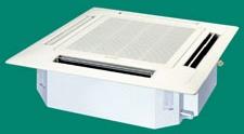
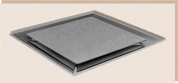
57 Page 57 of 58

58 Linear Slot Diffusers Page 58 of 58
AIR-CONDITIONING SYSTEMS AND APPLICATIONS. Abdullah Nuhait Ph D. King Saud University
 AIR-CONDITIONING SYSTEMS AND APPLICATIONS Abdullah Nuhait Ph D. King Saud University AIR-CONDITIONING SYSTEMS Earliest air conditioning system used only for heating (winter) Provided heated air for comfort
CHAPTER 4. HVAC DELIVERY SYSTEMS
 CHAPTER 4. HVAC DELIVERY SYSTEMS 4.1 Introduction 4.2 Centralized System versus Individual System 4.3 Heat Transfer Fluids 4.4 CAV versus VAV Systems 4.5 Common Systems for Heating and Cooling 4.6 Economizer
HVAC DISTRIBUTION and DELIVERY SYSTEMS
 HVAC DISTRIBUTION and DELIVERY SYSTEMS (Part 1) Ball State Architecture ENVIRONMENTAL SYSTEMS 2 Grondzik 1 REMINDER HVAC = Heating, Ventilating, Air-Conditioning The AC part of HVAC implies a system that
BOOK 1 OVERVIEW RD2XRT INSTALLATION AND OPERATION MANUAL. Table of Contents ABOUT BOOK 1:
 4510 Helgesen Drive, Madison, WI, 53718 608.221.4499, 800.627.4499, Fax: 608.221.2824 support@renewaire.com www.renewaire.com RD2XRT INSTALLATION AND OPERATION MANUAL BOOK 1 OVERVIEW ABOUT BOOK 1: This
Dehumidifying with Dedicated Outdoor Air
 Dehumidifying with Dedicated Outdoor Air System Configurations Figure 71. Configurations for dedicated outdoor-air systems A dedicated outdoor-air handler separately filters, cools, dehumidifies, heats,
Topic 2. ME 414/514 HVAC Systems Overview Topic 2. Equipment. Outline
 ME 414/514 HVAC Systems Overview Equipment Outline 2-1 The Complete System 2-2 The Air-Conditioning and Distribution System 2-3 Mechanical Equipment Air-handling Equipment Heating Equipment Boilers Furnaces
BOOK 1 OVERVIEW RD2XIN INSTALLATION AND OPERATION MANUAL. Table of Contents ABOUT BOOK 1:
 4510 Helgesen Drive, Madison, WI, 53718 608.221.4499, 800.627.4499, Fax: 608.221.2824 support@renewaire.com www.renewaire.com RD2XIN INSTALLATION AND OPERATION MANUAL BOOK 1 OVERVIEW ABOUT BOOK 1: This
SYNOPSIS. Part-Load Control Strategies for Packaged Rooftop Units. In this issue... Bin Hour Profile Charlotte, NC
 VOLUME ONE NUMBER THREE SYNOPSIS A N H V A C N E W S L E T T E R F O R B U I L D I N G O W N E R S A N D M A N A G E R S In this issue... Part-Load Strategies Why they re important.......... 1 What Things
Engineering Guide VAV Diffusers. Please refer to the Price Engineer s HVAC Handbook for more information on VAV Diffusers.
 VAV Diffusers lease refer to the rice Engineer s HVAC Handbook for more information on VAV Diffusers. Diffuser Types Ceiling Diffusers Conventional air distribution systems typically group several rooms
Air Conditioning Clinic
 Air Conditioning Clinic VAV Systems One of the Systems Series July 2012 TRG-TRC014-EN VAV Systems One of the Systems Series A publication of Trane Preface VAV Systems A Trane Air Conditioning Clinic Figure
ASHRAE JOURNAL ON REHEAT
 Page: 1 of 7 ASHRAE JOURNAL ON REHEAT Dan Int-Hout Chief Engineer Page: 2 of 7 Overhead Heating: A lost art. March 2007 ASHRAE Journal Article Dan Int-Hout Chief Engineer, Krueger VAV terminals provide
INTRODUCTION HVAC BASICS AND HVAC SYSTEM EFFICIENCY IMPROVEMENT SECTION O 4/19/2012
 HVAC BASICS AND HVAC SYSTEM EFFICIENCY IMPROVEMENT SECTION O INTRODUCTION HVAC systems or Heating, Ventilating and Air-Conditioning systems control the environment for people and equipment in our facilities.
Chapter 6 ALL-AIR HVAC SYSTEMS 6.1 CONTEXT
 Chapter 6 ALL-AIR HVAC SYSTEMS 6.1 CONTEXT This chapter and the following chapters on air-and-water and all-water systems are based upon a common context. Key to this context is the idea of a thermal zone.
Job Name Control Systems Description Date
 Job Name Control Systems Description Date Project Overview The project is a describe the building and its major HVAC systems (e.g. three-story office building, served by a rooftop unit VAV system ). In
HVAC Design Overview of Variable Air Volume Systems
 PDHonline Course M252 (4 PDH) HVAC Design Overview of Variable Air Volume Systems Instructor: A. Bhatia, B.E. 2012 PDH Online PDH Center 5272 Meadow Estates Drive Fairfax, VA 22030-6658 Phone & Fax: 703-988-0088
Selection of air conditioning systems
 Selection of air conditioning systems Prof. M. Ramgopal Department of Mechanical Engineering IIT Kharagpur Objectives 1. List the criteria used in the selection of air conditioning systems 2. List typical
UFAD and Displacement Ventilation. Dan Int-Hout, FASHRAE Chief Engineer Krueger Richardson, Texas
 UFAD and Displacement Ventilation Dan Int-Hout, FASHRAE Chief Engineer Krueger Richardson, Texas UFAD and DV Systems, Objectives: Understand Differences between: Well Mixed, Partially Stratified and Fully
UNIVERSITY OF MISSOURI Heating Ventilating and Air-Conditioning (HVAC) 2016 Q1
 2016 Q1") GENERAL: This section provides general standards for overall sizing and design of Heating, Ventilating, and Air Conditioning (HVAC) systems. Other sections contain specific standards for each system per
GENERAL: This section provides general standards for overall sizing and design of Heating, Ventilating, and Air Conditioning (HVAC) systems. Other sections contain specific standards for each system per
Retrocommissioning Findings Summary: Building X #1 Priority: Major Comfort/Control Problems
 IMPORTANT NOTICE: This sample document is provided for instructional purposes only. CCC is not rendering advice concerning any commission project or practices. This document is neither approved nor intended
Appendix 13. Categories of Cooling and Heating systems
 EcoShopping - Energy efficient & Cost competitive retrofitting solutions for Shopping buildings Co-funded by the European Commission within the 7 th Framework Programme. Grant Agreement no: 609180. 2013-09-01
APPLICATION GUIDE BEAMS
 BEAMS There is an increasing need for energy efficient air conditioning systems as energy codes become more stringent. Chilled beam systems are one such alternate to traditional all air conditioning systems.
HVAC 101. H V A C S y s t e m s
 H V A C 1 0 1 S y s t e m s Introduction & Overview Should you care? Mechanical System Types Components & operation Popular Application Key Issues and Design Considerations System Comparisons First Cost
Senior Thesis Centre Community Hospital East Wing Addition - Proposal Keith Beidel Mechanical Option 12/05/02 1
 Table of Contents Page Number(s) Executive Summary 2 Project Background 3 Proposed Depth Alternatives 4 Proposed Depth Redesign 5-7 Justification of Proposed Depth Redesign 8 Proposed Breath Redesign 9
HAP e-help. Modeling Induction Beams in HAP v4.8 QB TIP 001
 This HAP e-help provides a high-level overview of induction beams, how they work and how to model them in HAP 4.8 (and later versions). The first half of the article explains how induction beams work.
COMMERCIAL HVAC PACKAGED EQUIPMENT. Rooftop Units Level 1: Constant Volume
 COMMERCIAL HVAC PACKAGED EQUIPMENT Rooftop Units Level 1: Constant Volume Technical Development Programs (TDP) are modules of technical training on HVAC theory, system design, equipment selection and application
HVAC Optimization with Cold Air Distribution
 PDHonline Course M186 (2 PDH) HVAC Optimization with Cold Air Distribution Instructor: A. Bhatia, B.E. 2012 PDH Online PDH Center 5272 Meadow Estates Drive Fairfax, VA 22030-6658 Phone & Fax: 703-988-0088
product application data PERFECT HUMIDITY DEHUMIDIFICATION SYSTEM
 product application data PERFECT HUMIDITY DEHUMIDIFICATION SYSTEM 551B 581B DuraPac Plus Series Sizes 036-150 3to12 1 / 2 Tons Cancels: New PAD 551B.36.2 10/1/04 CONTENTS Page INTRODUCTION.................................
Temperature Control and Zoning of UFAD Systems
 Temperature Control and Zoning of UFAD Systems Presented by TROX USA Raised access flooring systems have become a very popular conduit for the delivery of power, voice and data services, as their accessibility
HVAC Controls Upgrades: Requirement Details ( )
") REQUIRED CONTROLS/FEATURES To qualify the upgrade must add or substantially modify 3 or more sequences/system capabilities. Also, all sequences and items listed under the required section are needed in
REQUIRED CONTROLS/FEATURES To qualify the upgrade must add or substantially modify 3 or more sequences/system capabilities. Also, all sequences and items listed under the required section are needed in
1080 Marina Village Parkway, Suite 501 Alameda, CA (510) Fax (510) HVAC DESIGN INTENT
 Fax (510) HVAC DESIGN INTENT") Taylor Engineering 1080 Marina Village Parkway, Suite 501 Alameda, CA 94501-1142 (510) 749-9135 Fax (510) 749-9136 LLC HVAC DESIGN INTENT PART 1 - GENERAL 1.1 Overview A. The project consists of a 3-story
Taylor Engineering 1080 Marina Village Parkway, Suite 501 Alameda, CA 94501-1142 (510) 749-9135 Fax (510) 749-9136 LLC HVAC DESIGN INTENT PART 1 - GENERAL 1.1 Overview A. The project consists of a 3-story
SECTION SEQUENCE OF OPERATIONS FOR HVAC CONTROLS
 SECTION 23 09 93 SEQUENCE OF OPERATIONS FOR HVAC CONTROLS PART 1 - GENERAL 1.1 SUMMARY A. This Section includes control sequences for HVAC systems, subsystems, and equipment. B. See Division 23 Section
REPRODUCTION/DISTRIBUTION IS PROHIBITED. Energy-Savings Strategies for. Rooftop
 Energy-Savings Strategies for Rooftop VAV Systems Occupied set-point temperature Unoccupied set-point temperature Rooftop variable-air-volume (VAV) s are used to provide comfort in a wide range of building
DESIGNING MODULAR VAV SYSTEMS
 FORM 5.2 REV 0905 THERMA-FUSER THERMALLY POWERED VAV DIFFUSER DESIGNING MODULAR VAV SYSTEMS MODULAR VAV SYSTEMS The Therma-Fuser diffuser is a simple stand alone device that provides VAV control when supplied
IAQ: Re-tuning Commercial Buildings
 IAQ: Re-tuning Commercial Buildings A low-cost path to improved air quality and energy efficiency. B y S c o t t G o r d o n, C M All images courtesy of Johnson Controls Service. 10 RSES Journal FEBRUARY
Single Zone System. One duct system Used mostly in small buildings Forced air system All spaces controlled by a single thermostat Single air return
 Single Zone System One duct system Used mostly in small buildings Forced air system All spaces controlled by a single thermostat Single air return Multi Zone System Used in small to medium sized buildings
SECTION SEQUENCE OF OPERATION FOR HVAC CONTROLS PART 1 GENERAL
 SECTION 15910 SEQUENCE OF OPERATION FOR HVAC CONTROLS PART 1 GENERAL 1.1 RELATED DOCUMENTS A. Drawings and general provisions of the Contract, including General and Supplementary Conditions and other Division
Verasys System Operation Overview Technical Bulletin
 Contents subject to change. Verasys System Operation Overview Technical Bulletin Code No. LIT-12012370 Issued January 2016 Refer to the QuickLIT Web site for the most up-to-date version of this document.
ENGINEERING. Edition No. 13 October 2002
 Edition No. 13 October 2002 ENGINEERING S Y S T E M S O L U T I O N S W e at McQuay are very proud of our tradition of producing industry leading water source heat pumps. Our heritage stretches back more
Union County Vocational - Technical Schools Scotch Plains, New Jersey
 SECTION 230593 - TESTING, ADJUSTING, AND BALANCING FOR HVAC PART 1 - GENERAL 1.1 SUMMARY A. Section Includes: 1. Balancing Air Systems: a. Constant-volume air systems. b. Variable-air-volume systems. 2.
Mechanical System Redesign. Dedicated Outdoor Air System. Design Criteria
 Mechanical System Redesign Dedicated Outdoor Air System Design Criteria The outdoor air conditions used were for Philadelphia, Pennsylvania IAP at a 0.4% occurrence. The supply air conditions were developed
Challenges and Methods of Estimating a Conceptual HVAC Design
 Challenges and Methods of Estimating a Conceptual HVAC Design ABSTRACT In any conceptual HVAC design, estimators are faced with the challenge of trying to capture all of the pieces that complete a system.
4-Pipe VAV vs. Active Chilled Beams for Labs
 Steven T. Taylor 4-Pipe VAV vs. Active Chilled Beams for Labs BY STEVEN T. TAYLOR, P.E., FELLOW ASHRAE Variable air volume (VAV) laboratory HVAC systems, including VAV fume hoods, are now standard practice
College of Technological Studies Department of Power & Refrigeration Technology. Course Contents
 College of Technological Studies Department of Power & Refrigeration Technology Course Contents Course Designation: Air Conditioning Control systems Course No. : 272 0463 Credit Hrs.: 3 Lecture Hrs.: 2
SESSION Michigan Energy Code (MEC) Update (3 Technical) Per SMACNA Standard (TAB, Duct Design) and ASHRAE ( ) ASHRAE Detroit Members:
 Update (3 Technical) Per SMACNA Standard (TAB, Duct Design) and ASHRAE ( ) ASHRAE Detroit Members:") SESSION 1-2015 Michigan Energy Code (MEC) Update (3 Technical) Per SMACNA Standard (TAB, Duct Design) and ASHRAE (90.1.2013) ASHRAE Detroit Members: AM Session is eligible for (X) Professional Development
SESSION 1-2015 Michigan Energy Code (MEC) Update (3 Technical) Per SMACNA Standard (TAB, Duct Design) and ASHRAE (90.1.2013) ASHRAE Detroit Members: AM Session is eligible for (X) Professional Development
Benefits Offered by Passive Dehumidification Wheel Speed Control
 Benefits Offered by Passive Dehumidification Wheel Speed Control White paper By John Fischer Benefits Offered by Passive Dehumidification Wheel Speed Control The most significant advantage of the Pinnacle
HVAC Mandatory Provisions Part II, Page 1
 HVAC Mandatory Provisions Part II, Page 1 Mandatory Equipment Efficiency Worksheet (6.4.1.1) System Equipment Type Size Category (Tables 6.8.1A through K) Sub-Category or Rating Condition Units of Efficiency
FORM EG2 (502) FlexSys Configured Packaged Rooftop Air Conditioning Units
 FlexSys Configured Packaged Rooftop Air Conditioning Units") FORM 100.50-EG2 (502) TM FlexSys Configured Packaged Rooftop Air Conditioning Units TABLE OF CONTENTS PAGE TOTAL INTEGRATED HVAC SYSTEM... 3 AN INTEGRATED SOLUTION... 4 INTRODUCTION... 6 System Description...
FORM 100.50-EG2 (502) TM FlexSys Configured Packaged Rooftop Air Conditioning Units TABLE OF CONTENTS PAGE TOTAL INTEGRATED HVAC SYSTEM... 3 AN INTEGRATED SOLUTION... 4 INTRODUCTION... 6 System Description...
Heat Pumps M2 SERIES. Modular Self-Contained Unit Water-Source Heat Pumps (3-70 tons) Features:
 Features:") Heat Pumps M2 SERIES Modular Self-Contained Unit Water-Source Heat Pumps (3-70 tons) Features: Water-source and geothermal heat pump self-contained units with capacities from 3-70 tons 10%-100% variable
Heat Pumps M2 SERIES Modular Self-Contained Unit Water-Source Heat Pumps (3-70 tons) Features: Water-source and geothermal heat pump self-contained units with capacities from 3-70 tons 10%-100% variable
Pharmaceutical Facility Design
 PhEn-602 Pharmaceutical Facility Design J. Manfredi Notes 9A PhEn-602 J. Manfredi 1 Primary & Secondary HVAC units Primary Primary air handling unit arrangement: One unit is responsible for all of the
August 15, 2013 Page 1 of 19
 Section C401 Application Compliance with C402, C403, C404 and C405 AND (either C406.2, C406.3 or C406.4) Compliance with C402, C403, C404 or C405 Section C402 Building Envelope (Climate Zone 5A) Space-Conditioning
Technical Report #3 Mechanical Systems Existing Conditions Evaluation
 Mechanical Option Technical Report #3 Technical Report #3 Mechanical Systems Existing Conditions Evaluation Instructor: Dr. Bahnfleth 11.15.04 Building Sponsor: CCG Facilities Integration Table of Contents
Selected Laboratory Energy Efficiency Measures
 Selected Laboratory Energy Efficiency Measures These are some of the most effective energy efficiency measures for laboratories 1. Reduce (optimize) air changes per hour in lab space 2. Design to the proper
Energy Recovery Ventilation
 Published on Business Energy Advisor (https://oncor.bizenergyadvisor.com) Home > Energy Recovery Ventilation Energy Recovery Ventilation Proper ventilation is essential for maintaining good indoor-air
EADQUARTERS. Technical Report One. Stephanie Kunkel Mechanical Option
 EADQUARTERS 707 N. Calvert St. Technical Report One ASHRAE Standard 62.1 Ventilation ASHRAE Standard 90.1 Energy Design Stephanie Kunkel www.engr.psu.edu/ae/thesis/portfolios/2011/slk5061 Mechanical Option
SECTION SEQUENCE OF OPERATIONS FOR HVAC CONTROLS
 PART 1 - GENERAL SECTION 23 09 93 SEQUENCE OF OPERATIONS FOR HVAC CONTROLS 1.1 SUMMARY A. This Section includes control sequences for HVAC systems, subsystems, and other equipment. B. See Division 23 Section
Heat Pumps SA SERIES. Vertical Self-Contained Unit Water-Source Heat Pumps (23-70 tons) Features:
 Features:") Heat Pumps SA SERIES SA Series Vertical Self-Contained Unit Water-Source Heat Pumps (23-70 tons) Features: Vertical self-contained units with capacities from 23 70 tons Direct drive backward curved plenum
Heat Pumps SA SERIES SA Series Vertical Self-Contained Unit Water-Source Heat Pumps (23-70 tons) Features: Vertical self-contained units with capacities from 23 70 tons Direct drive backward curved plenum
System Components with ` Emphasis on Packaged Rooftop Application and Installation. Jerry Cohen President Jacco & Assoc.
 System Components with ` Emphasis on Packaged Rooftop Application and Installation Jerry Cohen President Jacco & Assoc. Agenda Define and relate in practical terms the following components: System Effect
4. OVERVIEW OF MECHANICAL SYSTEM
 4. OVERVIEW OF MECHANICAL SYSTEM The 87,000 SF SLCC is served by six (6) Trane M-Series Climate Changer Air Handing Units (AHUs). Each unit serves a distinct zone within the facility that is unique in
Commercial Buildings Chilled water systems efficiency By Jens Nørgaard, Senior Application Manager, Grundfos, Denmark
 Commercial Buildings Chilled water systems efficiency By Jens Nørgaard, Senior Application Manager, Grundfos, Denmark Introduction: Energy use is the single largest operating expense in commercial office
INTRODUCTION TO: ASHRAE STANDARD 90.1, HVAC System Requirements for Reducing Energy Consumption in Commercial Buildings
 INTRODUCTION TO: ASHRAE STANDARD 90.1, 2013 HVAC System Requirements for Reducing Energy Consumption in Commercial Buildings Rocky Mountain ASHRAE Technical Conference, April 29, 2016 SEAN BEILMAN, P.E.,
ENGINEERING BULLETIN. Overview of Chilled Beam Technology. Purpose. Summary. Theory
 Overview of Chilled Beam Technology Purpose Chilled beam technology is new to the United States but has been used in Europe since the 1950 s. Chilled beams can reduce energy costs, improve indoor air quality,
Do All DOAS Configurations Provide the Same Benefits?
 TECHNIL FTURE This article was published in ASHE Journal, July 2014. Copyright 2014 ASHE. Posted at www.ashrae.org. This article may not be copied and/or distributed electronically or in paper form without
CARRIER edesign SUITE NEWS. Modeling 100% OA Constant Volume Air Systems. Volume 6, Issue 1. Page 1 Modeling 100% OA Constant Volume Air Systems
 Volume 6, Issue 1 CARRIER edesign SUITE NEWS Modeling 100% OA Constant Volume Air Systems This article provides an overview of how to model a stand-alone constant air volume (CAV) 100% OA system in HAP.
IDL20e (2 way discharge) IDS60e (4 way discharge) Inffusers. UDI (vertical discharge) Frequently Asked Questions
 IDS60e (4 way discharge) Inffusers. UDI (vertical discharge) Frequently Asked Questions") IDL20e (2 way discharge) IDS60e ( way discharge) Frequently Asked Questions UDI (vertical discharge) Inffusers INFFUSER FREQUENTLY ASKED QUESTIONS The following are frequently asked questions (FAQ s) on
IDL20e (2 way discharge) IDS60e ( way discharge) Frequently Asked Questions UDI (vertical discharge) Inffusers INFFUSER FREQUENTLY ASKED QUESTIONS The following are frequently asked questions (FAQ s) on
The Creative and Performing Arts High School (CAPA) Pittsburgh, PA 11/11/2002 Andrew Tech Mechanical Option Prof. S. A. Mumma
 Pittsburgh, PA 11/11/2002 Andrew Tech Mechanical Option Prof. S. A. Mumma") Objectives and Requirements For the Creative and Performing Arts High School (CAPA), the main objective of the mechanical design is to provide an energy efficient system that is easily maintainable and
Objectives and Requirements For the Creative and Performing Arts High School (CAPA), the main objective of the mechanical design is to provide an energy efficient system that is easily maintainable and
FAN TERMINAL UNITS Constant Volume (Series Flow), Standard Design
, Standard Design") FAN TERMINAL UNITS Constant Volume (Series Flow), Standard Design Fan motor (PSC or ECM). UL Listed 1 insulation conforms to UL Test 181 and NFPA 90A. Plenum air filter rack. (Filter Optional) Casing has
FAN TERMINAL UNITS Constant Volume (Series Flow), Standard Design Fan motor (PSC or ECM). UL Listed 1 insulation conforms to UL Test 181 and NFPA 90A. Plenum air filter rack. (Filter Optional) Casing has
Design Considerations For Dedicated OA Systems BY HUGH CROWTHER, P.ENG, MEMBER ASHRAE; YI TENG MA, ASSOCIATE MEMBER ASHRAE
 ASHRAE www.ashrae.org. Used with permission from ASHRAE Journal. This article may not be copied nor distributed in either paper or digital form without ASHRAE s permission. For more information about ASHRAE,
100% Outdoor Air Dehumidification Methods
 Technical Bulletin 16 100% Outdoor Air ehumidification Methods I NTROUCTION As consulting engineers and end users implement the ASHRAE 6 ventilation code, they are faced with selecting an appropriate method
GARCIA GALUSKA DESOUSA Consulting Engineers
 L#57295/Page 1/July 21, 2017 HVAC SYSTEMS NARRATIVE REPORT The following is the HVAC system narrative, which defines the scope of work and capacities of the HVAC system as well as the Basis of Design.
Heat Pumps SA SERIES. Vertical Self-Contained Unit Water-Source Heat Pumps (23-70 tons) Features:
 Features:") Heat Pumps SA SERIES Features: Vertical self-contained units with capacities from 23 70 tons Direct drive backward curved plenum and reduced maintenance Double wall rigid polyurethane foam injected panel
Heat Pumps SA SERIES Features: Vertical self-contained units with capacities from 23 70 tons Direct drive backward curved plenum and reduced maintenance Double wall rigid polyurethane foam injected panel
General HVAC Recommendations
 General HVAC Recommendations DESIGN GUIDELINES FOR ENERGY EFFICIENT HVAC SYSTEMS Thank you for your interest in energy efficiency! Energy efficient heating, ventilation, and air conditioning (HVAC) equipment
DEHUMIDIFICATION: Ice Arena Application & Product Guide. Design, construct and operate to control indoor humidity in ice rinks
 DEHUMIDIFICATION: Ice Arena Application & Product Guide Design, construct and operate to control indoor humidity in ice rinks Munters is the world leader in dehumidification Munters is the largest manufacturer
Raised Access Floor - (AE Breadth Area)
") Raised Access Floor - (AE Breadth Area) Currently, the Plaza has a raised access flooring system on both the 7 th and 8 th floors. The 8 th floor is designed with an independent HVAC system utilizing an
Raised Access Floor - (AE Breadth Area) Currently, the Plaza has a raised access flooring system on both the 7 th and 8 th floors. The 8 th floor is designed with an independent HVAC system utilizing an
D-PAC. Digital Precise Air Control System. Functionality Factory Testing Ease of Installation Ease of Maintenance Energy Efficiency
 Digital Precise Air Control System D-PAC Functionality Factory Testing Ease of Installation Ease of Maintenance Energy Efficiency AAON 24 South Yukon Avenue Tulsa, Oklahoma 747 (918) 583-2266 Fax (918)
DADANCO Technical Paper
 DADANCO Technical Paper 260 North Elm Street Westfield, MA 01085 Phone: (413) 564-5657 Fax: (413) 568-2969 March 2013 CLASSROOM SOLUTION USING ACTIVE CHILLED BEAMS (Note: This technical paper assumes the
Ball State Architecture ENVIRONMENTAL SYSTEMS 2 Grondzik 1. Contextual Reminder
 HVAC DISTRIBUTION and DELIVERY SYSTEMS (Part 2) Ball State Architecture ENVIRONMENTAL SYSTEMS 2 Grondzik 1 Contextual Reminder All-air systems Single zone Terminal reheat Multi-zone Dual-duct VAV Combinations
Chilled Beams. Getting a Warmer Reception
 Chilled Beams Getting a Warmer Reception Gain an understanding of how chilled-beam technology works, the difference between active/passive chilled beams and potential applications for its use. B y G r
PDHengineer.com. Course HV Centralized Vs Decentralized Air Conditioning Systems
 PDHengineer.com Course HV-4007 Centralized Vs Decentralized Air Conditioning Systems This document is the course text. You may review this material at your leisure before or after you purchase the course.
OSU Alumni Center Phase I Implementation Review. Oregon State University 130 Oak Creek Bldg. Corvallis, Oregon
 OSU Alumni Center Phase I Implementation Review Prepared for Oregon State University 130 Oak Creek Bldg. Corvallis, Oregon 97331 October 31, 2011 Job No. 02.11.00113 Introduction: Glumac was engaged by
7. MECHANICAL SYSTEM DESIGN
 7. MECHANICAL SYSTEM DESIGN The second primary topic of this thesis is to investigate the application of a dedicated outdoor air system (DOAS) to the SLCC. The stated goals for this thesis of improved
HVAC Controls Upgrades: Requirement Details ( )
") REQUIRED CONTROLS/FEATURES HVAC non CENTRAL PLANT 1) Zone Level Scheduling & Override for all air handlers (supply and exhaust) to match occupied hours by zone DDC or occupancy sensors (OS) allowed. (403.2.4.3,
REQUIRED CONTROLS/FEATURES HVAC non CENTRAL PLANT 1) Zone Level Scheduling & Override for all air handlers (supply and exhaust) to match occupied hours by zone DDC or occupancy sensors (OS) allowed. (403.2.4.3,
DESCRIPTION OF TECHNOLOGY
 March 2009 Underfloor Air Distribution INTRODUCTION Copyright 2009 Glumac. All rights reserved. While this Green Paper discusses primarily the use of raised access floors for air distribution, HVAC integration
Energy Savings Potential of Passive Chilled Beam System as a Retrofit Option for Commercial Buildings in Different Climates
 Purdue University Purdue e-pubs International High Performance Buildings Conference School of Mechanical Engineering 2014 Energy Savings Potential of Passive Chilled Beam System as a Retrofit Option for
City of Duluth Festival Center 04/25
 SECTION 230593 - TESTING, ADJUSTING, AND BALANCING FOR HVAC PART 1 - GENERAL 1.1 RELATED DOCUMENTS A. Drawings and general provisions of the Contract, including General and Supplementary Conditions and
A. Base Bid: 1. Heating Contractor provide: a. Control sequences for HVAC systems, subsystems, and equipment.
 SECTION 23 09 93 - SEQUENCE OF OPERATIONS FOR HVAC CONTROLS PART 1 - GENERAL 1 WORK INCLUDES A. Base Bid: Heating Contractor provide: Control sequences for HVAC systems, subsystems, and equipment. B. Alternate
NORTHWESTERN UNIVERSITY PROJECT NAME JOB # ISSUED: 03/29/2017
 SECTION 23 0594 - TESTING, ADJUSTING, AND BALANCING (TAB) PART 1 - GENERAL 1.1 SUMMARY A. This Section includes testing, adjusting and balancing HVAC systems to provide design conditions as indicated by
Comfort and health-indoor air quality
 Comfort and health-indoor air quality 1 The human body has a complicated regulating system to maintain the human body temperature constant most of the time, which is 98.6 F (36.9 C) regardless of the environmental
Rittling Induction Units Catalog
 Rittling Induction Units Catalog Heating Cooling Fresh Air Clean Air Zehnder everything you need to create a comfortable, healthy and energy-efficient indoor climate Heating, cooling, fresh and clean air:
COMMERCIAL HVAC EQUIPMENT Indoor Self-Contained Units
 COMMERCIAL HVAC EQUIPMENT Indoor Self-Contained Units Technical Development Program Technical Development Programs (TDP) are modules of technical training on HVAC theory, system design, equipment selection
PINNACLE SERIES DEDICATED OUTDOOR AIR SYSTEM ENERGY EFFICIENT DEHUMIDIFICATION
 ENERGY EFFICIENT DEHUMIDIFICATION PINNACLE SERIES DEDICATED OUTDOOR AIR SYSTEM Provides a very high degree of latent cooling using only a minimal amount of conventional cooling input Substantial energy
THIS IS A DESIGN GUIDE NOT A SPECIFICATION. Montgomery County Public Schools Facilities Guide DIVISION 15 MECHANICAL
 SECTION 15100 PART 1 GENERAL THIS IS A DESIGN GUIDE NOT A SPECIFICATION Montgomery County Public Schools Facilities Guide DIVISION 15 MECHANICAL HVAC SYSTEMS APPLICATIONS 1.1 SCOPE: The intent of this
Displacement Ventilation
 Displacement Ventilation Displacement Ventilation Displacement Ventilation vs. Dilution Ventilation Characteristics Design Considerations Layout and Selection Product Overview Casino Case Study Dilution
UNIFIED FACILITIES GUIDE SPECIFICATIONS
 USACE / NAVFAC / AFCEC / NASA UFGS-23 09 93 (November 2015) ----------------------------- Preparing Activity: USACE Superseding UFGS-23 09 23 (May 2011) UNIFIED FACILITIES GUIDE SPECIFICATIONS References
Fan Selection. and Energy Savings
 Fan Selection and Energy Savings Reducing power consumption by minimizing system pressure loss and choosing the right equipment HBy BRIAN MLEZIVA Greenheck Fan Corp. Schofield, Wis. Power Consumption HVAC
Hood Depot Internatioonal, Inc., Phone S. Powerline Road, Deerfield Beach, FL
 The Kitchen Cool by Hood Depot is a conditioned make up air unit design with flexibility, form and function kept in mind. Our unit offers a variety of configurations that allow the customer to customize
Technical Assignment 3 11/15/04. Executive Summary
 Executive Summary This report is an analysis of the existing systems within the Outreach Innovation Building in University Park, PA. One significant design criteria was a lower than average noise criteria
Complete Ventilation, Heat Recovery and Dehumidification Packaged System by. Maintaining Your Climate for Indoor Pools and Waterparks
 Ventilation Heat Recovery PoolPak International Maintaining Your Climate for Indoor Pools and Waterparks Complete Ventilation, Heat Recovery and Dehumidification Packaged System by PoolPak International
RSES Technical Institute Training Manual 3 72 hours, 72 NATE CEHs, 7.2 CEUs
 Lesson 1 - Basic Heat Pump Theory (Part 1) Describe the basic operation of a heat pump. Explain the function of various heat pump controls. Interpret the wiring diagrams and performance data provided by
Rooftop Ventilator. Models RV and RVE. with Packaged Cooling & Heating
 Rooftop Ventilator with Packaged Cooling & Heating Models RV and RVE Institutional Commercial Industrial 800-1,500 cfm.0 in. wg External Static Pressure Indirect Gas, Hot Water, Electric Heating Packaged
B. Use UT Austin specifications and equipment schedule format for HVAC equipment where available.
 PART 1: GENERAL 1.01 General Requirements A. This standard is intended to provide useful information to the Professional Service Provider (PSP) to establish a basis of design. The responsibility of the