Chapter 6 ALL-AIR HVAC SYSTEMS 6.1 CONTEXT
|
|
|
- Philip Cummings
- 5 years ago
- Views:
Transcription
1 Chapter 6 ALL-AIR HVAC SYSTEMS 6.1 CONTEXT This chapter and the following chapters on air-and-water and all-water systems are based upon a common context. Key to this context is the idea of a thermal zone. A zone is an area of a building that must be provided with separate control if design intent is to be met. From an HVAC system perspective the design intent that is most commonly of concern when establishing zones is the provision of thermal comfort. Providing for acceptable indoor air quality may also influence zoning decisions (as is noted later relative to VAV system analysis). Zoning should be established before system selection. Although costs and budget will typically influence system selection and the number of zones that can be reasonably provided, selection of a system that cannot provide the necessary zones means selection of a system that cannot provide desired comfort or IAQ. All central HVAC systems are assembled from four functional subsystems: a source subsystem, a distribution subsystem, a delivery subsystem, and a control subsystem. Source elements are discussed in Chapter 5 (along with components such as pumps and fans that comprise the distribution subsystem). Controls are discussed in Chapter 10. Distribution (moving heating/cooling effect from the source to the spaces requiring conditioning) and delivery (introducing the heating/cooling effect into each zone) are essentially the focus of Chapters 6, 7, and 8, which discuss all-air, air-and-water, and allwater distribution/delivery approaches. 6.2 INTRODUCTION Familiarity with the information on all-air systems presented in the Building Air Distribution chapter of the ASHRAE Handbook HVAC Systems and Equipment, which gives a general description of these types of systems, is assumed in this manual. Fundamental material from that resource is generally not repeated here. All-air systems provide sensible and latent cooling capacity solely through cold supply air delivered to the conditioned space. No supplemental cooling is provided by refrigeration sources within the zones and no chilled water is supplied to the zones. Heating may be accomplished by the same supply air stream, with the heat source located either in the central system equipment or in a terminal device serving a zone. A zone is an area controlled by a thermostat, while a room refers to a partitioned area that may or may not have a separate thermostat. The psychrometrics of air-conditioning systems are treated in detail in this chapter. Much of this psychrometric discussion is also applicable to the air-and-water and all-water systems discussed in Chapters 7 and 8.
2 6.3 ADVANTAGES AND DISADVANTAGES OF ALL-AIR SYSTEMS The general advantages of central systems (including all-air systems) include: Major equipment is centrally located in dedicated service spaces, which allows maintenance to take place in unoccupied areas. Major noise-generating equipment is centrally located in a space that can be acoustically isolated, allowing for reasonable noise control opportunities. There is no condensate drain piping or HVAC power wiring in occupied areas (as opposed to unitary or fan-coil systems). Among the specific advantages of all-air systems are: Such systems are well suited to air-side economizer use, heat recovery, winter humidification, and large-volume outdoor air requirements. They are the best choice for close control of zone temperature and humidity. They are generally a good choice for applications where indoor air quality is a key concern. They are amenable to use in smoke control systems. There is simple seasonal changeover. Such systems generally permit simultaneous heating and cooling in different zones. Among the disadvantages of all-air systems are: All-air systems use significant amounts of energy to move air (approximately 40% of all-air system energy use is fan energy). Ductwork space requirements may add to building height. Air balancing may be difficult. It is difficult to provide comfort in locations with low outdoor temperatures and typical building envelope performance when warm air is used for perimeter heating. Providing ready maintenance accessibility to terminal devices requires close coordination between mechanical, architectural, and structural designers.
3 All-air systems that have been used in buildings of various types are presented below. Not all of these systems are equally valid in the context of a given project. Not all of these systems see equal use in today s design environment. They are presented, however, to provide a sense of the possibilities and constraints inherent in the use of an all-air HVAC system. 6.4 SYSTEM CONCEPTS AND BASIC PSYCHROMETRICS Procedures for the calculation of air-conditioning cooling loads are presented in the ASHRAE Handbook Fundamentals and are summarized in Chapter 4 of this manual. Proper representation of each load on a psychrometric chart will help you understand the interaction of the loads and their effects on system design. Figure 6-1(A) shows a schematic diagram of a representative single-duct, single-zone, all-air system. Figure 6-1(B) shows a psychrometric analysis for this system in cooling mode; Figure 6-1(C) shows a heating mode analysis. Heat flows (denoted as q) and airflows are indicated by arrows, and temperatures are indicated as t. Subscripts identifying points in the sequence of airflow are: R = room rp = return plenum rd = return duct o = outdoor air m = mixed air cc = cooling coil leaving air temperature hc = heating coil leaving air temperature rf = return air fan sf = supply air fan sd = supply ductwork s = supply The room sensible and latent loads in Figure 6-1(B) are denoted by q SR and q LR, respectively, and the outdoor air sensible and latent loads are denoted by q So and q Lo, respectively. The total cooling load q cc is defined by the difference in enthalpies between states m and cc. Note that the air discharged from the cooling coil absorbs heat from the supply air fan and the supply air ductwork before air enters the room accounting for the difference in dry-bulb temperature between points cc and s in Figure 6-1(B). Room sensible and latent loads due to occupants, lights, equipment, solar radiation, opaque envelope transmission, etc. are picked up and carried to the return air plenum by the return air stream. Additional heat may be picked up from recessed light fixtures, a floor or roof above, and a return air fan, accounting for the increase in temperature between points R and r. Some of the air is exhausted, while outdoor ventilation air (o) is taken in, resulting in a mixed air stream condition m, which is cooled and dehumidified by the cooling coils, producing the state of air at cc. In this arrangement a heating coil is provided immediately downstream of the cooling coil to raise the air temperature as required to provide winter
4 heating. Usually, the heating coil is upstream of the cooling coil and acts as a preheating coil in winter. Such an arrangement provides some freeze protection for a chilled water cooling coil. Fig 6-1 Single-Duct, Single-Zone System Schematic Diagram and Psychrometric Chart. Depending upon exactly how air is supplied to and exhausted from a room, larger or smaller portions of the heat gain from the lighting system may be either added to the other heat loads in the room or picked up in the return air plenum. This is explained in detail in the chapter on Nonresidential Air-Conditioning Cooling and Heating Load in the ASHRAE Handbook Fundamentals. When return air is routed through light fixtures (using troffer returns), the approximate fractions of heat removed by the return air stream under different conditions are shown in Table 6-1. Note that some designers believe these values are high. TABLE 6-1 Estimated Heat Removal a from Lighting Fixtures by Airflow Return airflow rate, cfm [L/s] 10 [4.7] 20 [9.4] 30 [14.2] 40 [18.9] Four-tube fixtures, 4 ft [1.2 m] long Two-tube fixtures, 4 ft [1.2 m] long a percent of total power input When a substantial portion of the heat of lighting is removed by the return air stream (thus reducing room cooling load), room supply air volume in a lightly-loaded space may fall short of the minimum ventilation air design criteria, particularly under part-load operation of a variable-air-volume system. Various methods to avoid this problem are described later. 6.5 SPECIAL DESIGN CONSIDERATIONS Pressure Considerations All-air systems may be designed for high or low velocity air distribution. Higher pressures may be desirable in some low-velocity systems for improved ease of balancing and/or for use of flow control regulators, which have a substantial pressure drop. Higher pressures are required with high-velocity systems to overcome greater friction losses in the ductwork. Make every effort to reduce the total energy needed to deliver the required airflow in a system. This will ensure a quieter system, reduce duct leakage, and, in the majority of cases, minimize operating costs. Duct design methods are noted in Section 5.8, which also presents maximum and recommended velocities for high-pressure and low-pressure systems. The chief justification for the use of high duct velocities is limited space for ductwork. Most designs have choke points where ducts must be restricted in size. As a result, the air velocity at such points must be high. As soon as these points are passed and space
5 becomes available, lower duct velocities should be restored to reduce friction, and the velocity then gradually decreased further toward the far end of the duct system. A substantial saving in duct friction is usually achieved by carefully studying the duct mains adjacent to the air-handling room. The connections from plenums to main supply ducts should be as streamlined as possible to reduce the friction loss at the entrance to the main distribution duct. In practice, this is usually accomplished by using a transitional fitting between the ductwork and the plenum. In many cases, space/volume is available at the air-handling room, and a large duct can be used in this area. The duct velocity can then be stepped up gradually as the point of maximum space restriction is reached. Return air ducts should be sized for low velocities. One way to simplify the return air system is to use suspended ceiling plenums or corridors as return ducts and to collect the return air at central points on each floor. In some localities, however, there are code restrictions to this method. One way to assist in providing a quiet installation is to provide a length of lined ductwork on the leaving side of terminal units when the system layout permits. Acoustically lined ductwork, especially when it contains one or two elbows, is a reasonably effective sound attenuator. It will provide a necessary acoustical safety factor if noise regeneration occurs in the air distribution system because of poorly constructed ducts, fittings, or taps. Noise and vibration control are treated in more detail in Section Air Temperature-Volume Considerations The volume of air required to condition any space can be governed by the room design sensible cooling load, by the room dehumidification or humidification (latent) load, or by room ventilation requirements. (In HVAC terminology, "ventilation" refers to outdoor or fresh air flow, not to total air circulation.) Ventilation requirements, however, are rarely the governing condition, although they may govern under minimum supply air conditions in variable-air-volume (VAV) systems (see Section 6.8) or in rooms with high occupancy or high exhaust air requirements. Although loads, ventilation or air movement requirements, and equipment limitations may to some extent predetermine supply air volume and temperature values, the system designer often has some latitude in selecting the temperature-volume relationship. Weigh the economics of low-volume (high delta-t) supply air against possible distribution, odor, or air movement problems. Low-volume air supply (resulting from lower than normal supply air temperatures) increases operating costs for refrigeration, although overall operating costs (considering both refrigeration and air distribution systems) do not necessarily increase. Low supply temperatures may cause drafts and condensation on diffuser/register surfaces. For occupant comfort, it is undesirable to inject air into a room that is more than 20 F [11 C] colder than the room air temperature. When the supply air is colder than that, for example in cold air systems (see Section 9.3.8), supply air must be mixed with induced room air inside the supply terminal before being injected into the room.
6 6.6 USEFUL EQUATIONS FOR AIRSIDE SYSTEM DESIGN Basic Calculations 1. Sensible heat capacity or load; q s (Btu/h) [W] q s = (specific heat) (density) (mass flow rate) (temperature difference) q s = (0.244 Btu/lb F) (0.075 lb/ft 3 ) (60 min/h) (cfm) ( t) q s = (1.1) (cfm) ( t) (6-1a) [q s = (1.006 kj/kg K) (1.204 kg/m 3 ) (1000 W/s kj) (0.001 L/m 3 ) ( t)] [q s = (1.2) (L/s) ( t)] (6-1b) where, q s = sensible heat corresponding to a change in dry-bulb temperature ( t) for a given volumetric flow of standard air cfm [L/s] = airflow rate of standard air, cubic feet per minute [liters per second] (While the specific heat of air is Btu/lb [0.558 kj/kg], the value [0.568] represents the specific heat of air with an average of 1% moisture.) 2. Latent heat capacity or load; q L (Btu/h) [W] q L = (latent heat of vaporization) (mass flow rate) (difference in humidity ratio) q L = (1076 Btu/lb water) (0.075 lb air/ft 3 ) (60 min/h) ( W) q L = (4840) (cfm) ( W) (6-2a) also equal to (0.69) (cfm) ( G) [q L = (2503 kj/kg water) (1.20 kg air/m 3 ) (0.001 L/m 3 ) ( W)] [q L = (3.0) (L/s) ( W) (6-2b) where, q L = latent heat corresponding to the change in (absolute) humidity ratio W = change in humidity ratio, pound of water per pound of dry air [g/kg] G =change in humidity ratio, grains of water per pound of dry air for given volumetric flow of standard air, where 7000 grains equal 1 pound 3. Total heat capacity or load; q t (Btu/h) [W] q t = (air mass flow rate) (change in enthalpy) q t = (0.075 lb/ft 3 ) (60 min/h) (cfm) ( h) q t = (4.5) (cfm) ( h) = q s + q L (6-3a)
7 [q t = (1.20 kg air/m 3 ) (0.001 L/m 3 ) (1000 W/s kj) (L/s) ( h)] [q t = (1.2) (L/s) ( h)] (6-3b) = q s + q L where, q t = total heat corresponding to change in enthalpy for given volumetric flow of standard air h = difference in enthalpy, Btu/lb [kj/kg] 4. Air Mixtures When air flowing at a rate of cfm 1 [L/s 1 ] at temperature t 1 and humidity ratio W l mixes with another airflow of cfm 2 [L/s 2 ] at t 2 < t l and W 2 < W l to yield a mixed condition of cfm m [L/s m ] at t m and W m, then cfm m = cfm l + cfm 2 [L/s m = L/s l + L/s 2 ] (6-4) t m = t 2 + (t 1 - t 2 ) (cfm l / cfm m ) [t m = t 2 + (t 1 - t 2 ) (L/s l / L/s m )] or t m = t l - (t l - t 2 ) (cfm l / cfm m ) [t m = t l - (t l - t 2 ) (L/s l / L/s m )] (6-5a) (6-5b) W m = W 2 + (W l - W 2 ) (cfm l / cfm m ) [W m = W 2 + (W l - W 2 ) (L/s l / L/s m )] (6-6a) or W m = W l - (W 1 - W 2 ) (cfm 2 / cfm m ) [W m = W l - (W 1 - W 2 ) (L/s 2 / L/s m )] (6-6b) In the above mentioned equations, t applies to either dry-bulb or wet-bulb air temperature. Such mixing processes, plotted on a standard psychrometric chart, fall on a straight line drawn between states 1 and 2, with the distances from these points inversely proportional to the respective flow rates Fan Laws The fan laws are used to predict the effect on fan performance of a change in the properties of air, fan operating speed, or fan size. The fan laws are given here in one of their several variations (see the ASHRAE Pocket Guide or the ASHRAE Handbook HVAC Systems and Equipment for these laws in equation format). Five commonly used versions of the fan laws state: 1. Given a variation in fan speed constant density of air, constant system (no change in ductwork or damper position) then: Q varies as rpm SP varies as rpm 2 VP varies as rpm 2 P varies as rpm 3
8 where, Q = flow rate of air SP = static pressure VP = velocity pressure P = fan power 2. Given a variation in fan size similar fan proportions, constant rpm, constant air density then: Q varies as D 3 SP varies as D 2 P varies as D 5 where, D = diameter of fan wheel 3. Given a variation in air density constant system, constant fan size, constant fan speed then: Q remains constant SP varies as air density P varies as air density 4. Given a variation in air density constant static pressure, constant system, constant fan size, variable rpm then: Q varies as (air density) -0.5 SP is constant rpm varies as (air density) -0.5 P varies as (air density) Given a variation in air density constant mass flow of air, constant system, constant fan size, variable rpm then: Q varies as the reciprocal of air density SP varies as the reciprocal of air density rpm varies as the reciprocal of air density P varies as (air density) -2 Some typical applications of the fan laws are presented below. Fan law 1. To find the necessary increase in fan rpm to increase the airflow rate by a specified amount. Fan law 2. To find the necessary change in fan size to achieve a greater flow rate, with operating speed remaining constant.
9 Fan law 3. To find the change in static pressure and power if air density changes but fan speed remains constant. Fan law 4. To find the speed change necessary to maintain a certain static pressure if air density changes. Fan law 5. To find the amount by which rpm must be changed when air density changes if a fixed mass rate of airflow is to be maintained (for example, to preserve a change in temperature across a heat exchanger with a fixed rate of heat addition). Fan laws 1 and 5 are most often used in design. If system testing and balancing shows that a 15% greater flow rate is required, fan law 1 indicates not only how much the fan speed must be increased, but what the consequences are on the power draw of the fan motor. Fan law 5 may be used when the air handled by a fan and duct system is at an appreciably different temperature from the temperature for which equipment ratings are available. This fan law may also be used when designing systems to operate at high altitudes (and thus lower atmospheric pressures) than sea level. Fan law 3 may provide an order-of-magnitude estimate of the change in fan size needed to achieve a revised flow rate, but realistically it would be better to consult a fan manufacturer's catalog for such information. Example 6-1. A fan installed in a new system operates at 800 rpm and provides a measured flow rate of 4100 cfm [1935 L/s] working against a static pressure of 2.8 in. of water [697 Pa]. The catalog rating of the fan at these conditions specifies a power requirement of 4.5 hp [3.4 kw], and a 5-hp [3.7 kw] motor has been selected. Instead of the current flow rate of 4100 cfm [1935 L/s], 4500 cfm [2124 L/s] is desired. What are the consequences of increasing the fan speed to achieve 4500 cfm [2124 L/s]? Solution: Fan law 1 states that, with constant air density and system characteristics, Q varies linearly with rpm. a. The fan speed must, therefore, be changed to: (800) (4500 / 4100) = 878 rpm, or by a ratio of [the same pattern applies to flows in L/s] b. The new static pressure will be (2.8) (1.0975) 2 = 3.37 in. of water [839 Pa]. c. The revised power requirement will be (4.5) (1.0975) 3 = 5.95 hp [4.4 kw], which will likely necessitate changing the 5-hp [3.7 kw] motor to a 7.5-hp [5.6 kw] motor. Figure 6-2 shows the original and revised operating conditions. Fig. 6-2 Original and Revised Operating Conditions for Example 6-1. Example 6-2. Measurements made on a newly installed air-handling system show: rpm fan speed, 4500 cfm [2124 L/s], l.9 in. of water [473 Pa] static pressure, and 3-hp [2.2 kw] shaft power when the air temperature is 70 F [21.1 C] and the pressure is standard atmospheric. In actual use, the fan and duct system are to handle 150 F [65.6 C]
10 air. If the fan speed remains 1200 rpm, what will be (a) the volume rate of airflow, (b) the static pressure, and (c) the power requirement? Solution: Fan law 3 applies because the air density changes, but the fan speed, fan size, and system characteristics remain constant. a. The volume rate of flow remains constant at 4500 cfm [2124 L/s]. The mass rate of flow, however, decreases because the air density at 150 F [65.6 C] is lb/ft 3 [1.04 kg/m 3 ] in comparison to lb/ft 3 [1.20 kg/m 3 ] at the original conditions. b. The static pressure varies in proportion to the air density, so SP = (1.9) (0.065 / ) = 1.65 in. of water [411 Pa]. c. The power varies in proportion to the air density, so P = (3 hp) (0.065 / ) = 2.61 hp [1.95 kw]. In the selection and operation of a combination of supply and return air fans, an underlying objective is to regulate the air pressures in the occupied spaces so that they are close to outdoor atmospheric pressure usually just slightly higher to reduce infiltration. This objective becomes a special challenge in VAV systems (Section 6.8), where the duct-damper characteristics are constantly changing as the zone loads change. 6.7 SINGLE-ZONE ALL-AIR SYSTEMS The simplest form of HVAC&R system is a single refrigeration machine serving a single temperature control zone (as per Figure 6-1). The equipment may be installed within or remote from the space it serves and may operate with or without distributing ductwork. If located within the zone being conditioned and without substantial ductwork the system is termed a local system. If located remote from the zone(s) being served and with distribution ductwork the system is termed a central system. Properly designed systems of either type can closely and effectively maintain temperature and humidity and can be shut down when desired without affecting the conditioning of other areas. They are fairly energy efficient, easy to control, and easily adaptable to economizer cycles (see Section 9.3.7). Their disadvantage is that they respond to only one set of space conditions. Their use is therefore limited to situations where variations occur approximately uniformly throughout the space served or where the load is stable i.e., a single zone situation. Single-zone systems are applicable to small department stores, small individual stores in a shopping center, individual classrooms in a school, computer rooms, hospital operating rooms, and large open areas (such as gymnasiums, atriums, and warehouses). A rooftop unit, complete with refrigeration system, serving an individual space is considered a single-zone system. The refrigeration system, however, may be remote and may serve several single-zone units in a larger installation. A return fan is necessary only if 100% outdoor air is used for cooling, and even then it may be eliminated if air can be relieved from the space with very little pressure loss through the relief system.
11 Units that incorporate all the components of an air-conditioning system except ductwork and condenser water piping are referred to as self-contained or packaged units because they contain a refrigeration compressor, a direct expansion coil, the refrigeration piping, a fan and motor, filter, and controls, all in one casing. In many cases, a heating coil is also included. Sometimes the units are attached to ductwork, but frequently they are used with a free-discharge register or diffuser. Such units are manufactured with either water-cooled or air-cooled condensers and with or without gas heating units. Frequently the fan and evaporator section of self-contained units is mounted in or next to the conditioned space, and the compressor-condenser unit is mounted on the roof or at some other remote location (see Section 6.12). In this case, refrigerant piping must be installed to connect the evaporator and the compressor, in an arrangement referred to as a split system. A building using multiple split-system units has a collection of single-zone systems. A single-zone system can be controlled by varying the quantity or the temperature of the supply air through the use of reheat, face and bypass dampers, volume control devices, or a combination of these. Single-duct systems without reheat offer cooling flexibility but cannot control humidity independently of temperature. Single-duct systems with reheat provide flexibility in both temperature and humidity control; a cooling coil cools the supply air to the desired humidity, and a reheat coil raises the dry-bulb temperature to the desired value. ASHRAE Standard 90.1, however, severely restricts the application of reheat, limiting this option to special cases. A separate humidifier and/or dehumidifier may have to be provided if tight control of humidity is required. Appendix B presents sample design calculations for a single-zone system. 6.8 VARIABLE-AIR-VOLUME (VAV) SYSTEMS System Concepts In constant-air-volume systems, cooling or heating control is accomplished by varying the supply air temperature while the volume of supply air remains constant. Variable-airvolume (VAV) systems accomplish cooling/heating control by maintaining constant air temperature while varying the volume of the air supply. Both control approaches have benefits and disadvantages Simple VAV This system applies to cooling-only applications with no requirement for simultaneous heating and cooling in different zones. A typical application is the interior of an office building. There are several means of varying system air flow in response to zone loads. Variations in system supply volume can occur without fan volume variation through use of a fan bypass. This type of control, however, negates the potential of fan energy savings available with a VAV system. VFDs (variable frequency drives) are reliable and relatively inexpensive, making a bypass control approach unwise. Alternatively, a
12 varying zone air volume can be obtained (while fan and system volume remain substantially constant) by dumping excess supply air into a return air ceiling plenum or directly into the return air duct system. Dumping cold air into a return air plenum, however, wastes energy and can cause overcooling under low load conditions due to air leakage through the ceiling system and radiant cooling from the ceiling surface. Dumping can also cause a shortage of system supply volume if it is used for system balancing as well as a means of temperature control. This control approach also fails to tap into the energy savings available if fan operation is adjusted to match reduced air flow needs. A variable speed drive (VFD) will capture this opportunity (assuming that zone loads actually vary) and is the most energy efficient VAV option VAV Reheat or VAV Dual Duct By sequencing reheat or blending air streams at each zone after throttling the zone's cold air supply via VAV control, full heating/cooling flexibility can be achieved much more energy-efficiently than with comparable constant-volume systems. This approach can be applied to both interior and perimeter spaces. The fan volume control options described above can be used with a preference for the use of a variable speed drive VAV with Independent Perimeter System All-air cooling and heating can be accomplished using a VAV system to serve interior spaces in conjunction with a constant-volume perimeter system. The variable-volume system provides cooling (and only cooling) year-round, taking care of variations in all zone internal heat gains as well as building envelope solar gains. The perimeter system uses an outdoor/indoor temperature-scheduled, constant-volume air supply to offset envelope conduction/convection gains or losses. The perimeter system requires no zone control (except to improve operating economy) and no outdoor air component since the VAV system takes care of each zone's load variations (except opaque envelope loads) and all outdoor air ventilation requirements. If a hydronic perimeter heating system is provided, the VAV system provides cooling in all zones year round, while the perimeter heating system offsets winter transmission heat losses (but not summer transmission heat gains). Coordination between these two delivery systems is important to overall energy efficiency VAV with Constant Zone Air Flow Volume VAV terminal devices may contain fans to maintain minimum or constant supply air flow to a particular zone while the volume of system primary air that is supplied to the zone is varied. Such terminals are commonly referred to as fan-powered terminals. The air flow to the zone is kept constant by recirculating return air keeping the sum of the variable primary air (to meet loads) and the recirculated air substantially constant. This technique is particularly useful for zones with large variations in internal loads, such as conference rooms. It may also be combined with terminal reheat. Or, return air from the interior can be transferred to perimeter fan-powered boxes to avoid terminal reheat. Fan-powered
13 terminals can be used to ensure good air circulation in occupied spaces during periods of reduced cooling load VAV with Economizer Cycle When the enthalpy (total heat content) of the outdoor air is lower than that of the return air, energy consumption for cooling can be reduced by taking in more outdoor air than required for ventilation and relieving the excess return air to the outdoors. Under favorable conditions, all of the return can be relieved and replaced by outdoor air. This mode of operation is called an airside economizer cycle (see Section 9.3.7). While this approach requires large outdoor air intake and relief/exhaust components, it improves economy of operation except in areas, such as the southeastern United States, where such favorable enthalpy conditions occur so rarely that the additional first cost of providing for economizer operation is not justified (Mutammara and Hittle 1990) Applications Variable-air-volume systems are easy to control, can be highly energy efficient, allow fairly good zone control, are easily adaptable to economizer cycles, and provide flexibility for zoning changes. A potential drawback includes the possibility of poor ventilation resulting in the potential for unacceptable indoor air quality, particularly under low zone loads. VAV systems are suitable for offices, classrooms, and many other applications, and are currently the system of choice for most commercial and institutional buildings despite the fact that humidity control under widely varying latent loads can be difficult, as illustrated in Figure 6-3 and in Appendix C VAV Design Considerations Psychrometric Analysis A typical arrangement of components for a variable-air-volume system with separate perimeter heating is shown schematically in Figure 6-3, with typical psychrometric performance for maximum and partial loads and for summer and winter operation. For cooling-only applications, air is delivered to a space at a fixed supply temperature that (at design flow rate) can offset the design space cooling load. The space thermostat reduces the volume of supply air when the cooling load is less than the design load. If some warm-up is desired after system shutdown, a heating coil may be installed and manually or automatically actuated for warm-up only. When system supply air is throttled while outdoor air volume is kept constant, tempering of the outdoor air may be necessary under cold winter ambient conditions. Equations (6-1) through (6-6) above apply for fan gains, ceiling temperatures, and air mixtures. Zone ductwork and variable-volume terminals must be sized for the governing load factor, either sensible, latent, or ventilation loads. The designer must determine the maximum system air volume from either (1) coincident system (block) load or (2) block sensible load plus all air requirements from governing latent or ventilation loads that exceed the volume required in any zone to satisfy the
14 sensible load in that zone when the entire system reaches its peak sensible load. Thus, if a system load peaks at 4 PM and an east zone's air requirement from sensible loads is less than the volume required by its latent or ventilation loads at that time, the latter volume must be used for that zone and an appropriate temperature control strategy applied. Actively controlling for non-sensible dominant loads is problematic, as discussed below. Fig 6-3 Variable-Air-Volume System Schematic Diagram and Psychrometric Chart. If building operators set thermostats below the values used for design calculations, more supply air will be required than the amount determined by the block load. Under these conditions, zones would experience a shortage of supply air if the system was designed based upon block loads only. Such an occurrence is possible. Energy-efficient design practices suggest an indoor summer design temperature of 78 F [25.6 C] and some occupants may find that this setting provides marginal comfort, especially in the presence of high mean radiant temperature. Attempts by the building operator to correct for such discomfort may involve resetting temperature sensors below design conditions, leading to the above scenario. Designing to provide some flexibility in control, without drastically oversizing systems, is advisable. Whenever supply air volume is throttled at a given dew-point condition, dehumidification capacity decreases. (This effect may be offset somewhat if reduced air flow through the cooling coil results increased dehumidification due to increased coil-air contact). The effect of reducing air volume on dehumidification capacity is illustrated in Figure 6-3, where R1 and R4 represent zones with high and low latent loads. Spaces with high latent loads must be carefully examined on the psychrometric chart before the proper air volume can be determined. Some designers prefer to design zones governed by latent or ventilation loads as constant-volume zones because a thermostat cannot respond to variations in either of those loads. This strategy ensures a sufficient supply air volume under all conditions, although the wisdom of mixing systems must be considered and the tendency to employ reheat for constant volume control resisted. As each zone peaks at a different time of day, it borrows the extra air required to meet its peak load from off-peak zones. Such sharing of air between off- and on-peak zones occurs only in true variable-air-volume systems and represents a utilization of system diversity. Systems that dump excess supply air into a return air system or bypass it to a return duct may be using zone VAV temperature control principles, but their design supply air volume is the sum of the peaks which is circulated on a constant-volume basis. Such systems do not use smaller fans and main ducts than a constant-volume system and miss out on opportunities for reduced energy use (a major advantage of VAV systems); they should be considered obsolete. Be sure to examine minimum air quantities in each zone and in the system. First, check for adequate dehumidification (Equation 6-2) and ventilation (Section 3.3.3). Second, check the increase in back pressure resulting from terminal throttling and its effect on fans and ducts and their need for static pressure control. Third, check for potential noise problems in terminal devices arising from throttling. If, at minimum system volume, the
15 increase in static pressure at the fan discharge and at the last terminal device is not so large as to cause fan instability, distribution imbalance, or excessive pressure drop in the last terminal, volume regulation and/or system static pressure control may not be necessary. Such a system would be riding the fan curve, varying the delivered air volume with changing system static pressure. Without fan speed control, however, most of the potential energy savings will be lost by just throttling airflow and riding the fan curve. Distinguish between the minimum throttling ratio (ratio of throttled flow to full flow) in any zone and that in the system. The ratio can be as low as 0.25 in a zone with a peak of, for example, 3 cfm/ft 2 [15 L/s per m 2 ], without necessarily violating ventilation criteria, while the system ratio might never go below 0.5. The lower the system design static pressure, the smaller the duct network; the higher the throttling ratio, the less need there is for system static control. Static pressure controls can be used to maintain fan stability and distribution balance, to reduce operating costs, and to stabilize system sound generation characteristics. Minimum ventilation air quantities can be maintained by: Raising supply air temperatures on a system basis (although this must be done with caution as it can lead to high humidity on cool humid days, when sensible and latent loads are out of sync) Raising supply air temperatures using reheat on a zone-by-zone basis Providing auxiliary heat in a zone, independently of the air system. Full-zone air circulation can be maintained by: Individual zone recirculation (via terminal units) with blending of varying amounts of supply air with room air or ceiling plenum air Ceiling induction unit recirculation (as above). Oversized VAV terminals should be avoided. They tend to be noisy because they must always be throttled. Low-frequency noise (which is difficult to attenuate) can be replaced with high-frequency noise (which is easier to attenuate) by installing a piece of perforated metal upstream of the terminal box, sized to reduce the full flow pressure at the terminal by the amount needed to provide better acoustics. The multiple holes cause low frequencies to be "end reflected" and energy to be dissipated in forcing air through the multi-hole orifice. Unfortunately, the following relationship applies: (flow rate 2 ) / (flow rate 1 ) = (P 2 / P 1 ) 0.5 (6-7) which means that the orifice will exhibit a parabolic control function. In addition, airflow sensors do not provide adequate velocity pressure signals at low flow conditions to provide accurate terminal modulation.
16 When radiation is provided for perimeter heating (see Section ), size it to offset envelope transmission losses. Heat is supplied by radiation in proportion to outdoor temperature. The VAV system usually provides all outdoor air requirements for interior as well as perimeter zones. If it is assumed that radiation exactly offsets transmission loss, interior loads will cause the variable-air-volume terminal to remain open, providing ventilation requirements and air movement for comfort and odor control. In reality, such an assumption is hard to implement, thus the VAV box and radiation control valve should be sequenced so that the VAV box is at its cooling (and ventilation) minimum before the radiation valve starts to open. The same effect may be produced when a perimeter air system without outdoor air is used to offset transmission loads. The solid lines in Figure 6-3(B) represent average system conditions, while the dotted lines represent individual zone conditions. The psychrometric chart does not show variations in airflow; a drop in room sensible load with no change in latent load appears as a steeper internal SHR (sensible heat ratio) line (s-r1) due to the reduced air volume. A typical winter cooling condition for a cold climate is shown in Figure 6-3(C). The moisture level is reduced due to mixing of return air with low-dew-point outdoor air. Supply air temperature at s is maintained by controlling the outdoor air dampers and return air dampers to produce the mixed-air state m. Some preheating may be needed to maintain the state, which would further reduce the space relative humidity. Temperature is maintained at each individual zone in the system by reducing zone airflow. Again, relative humidity may rise as sensible loads are reduced. All the preceding considerations apply when a separate perimeter radiation system handles the perimeter transmission and infiltration heating loads, while a common air system (serving both interior and perimeter zones with the same temperature air) handles cooling Envelope Isolation System Some designers have used a perimeter system to handle all conduction/convection loads from the envelope, in effect thermally isolating the envelope from the rest of the building (except for solar gains). Such a system could be a hot-water radiation system or a separate air system along the perimeter, although water would be preferred in cold climates. The advent of improved-performance envelope assemblies, and particularly high-performance glazings, has generally made such systems unnecessary Air Volume Pay particular attention to evaluation of the expected patterns of loads in a VAV system, as such patterns will affect air flow volume. Likewise, carefully estimate loads for VAV zones so that terminals are not regularly operating at low percentages of design flow with the potential for reduced indoor air quality that can come from such reduced flows. Selection of supply outlets that can produce secondary air motion is desirable in VAV system design. Proper design may require a smaller t or higher-performance, aspirating-type outlets in order to enhance air movement.
17 A typical pressure distribution through the supply and return air sections of a VAV system is illustrated in Figure 6-4. A basic design goal is to size the supply and return fans along with the supply and return air distribution systems to maintain a slight positive pressure in the building spaces. Since the positions of the zone control dampers in a VAV system are constantly changing, however, one design combination cannot meet the pressure requirements at all operating conditions. The best compromise is automatically afforded by supply fan pressure control via a variable frequency drive (VFD), which produces an energy conservation advantage as well. Reduction in capacity of the supply fan drops the pressure at points A and B in Figure 6-4 in comparison to full-capacity operation of the fan. The result is that deviations from the desired zone pressures are minimized. Fig. 6-4 Pressure Distribution in Supply and Return Ducts of VAV System. Air distribution is very important in VAV systems as supply air volumes are continually changing. Give careful consideration to distribution and to sound pressure levels at maximum and minimum flow. If the combined sound pressure level of the terminal unit and diffuser at maximum flow is at least 3 decibels below the room ambient sound pressure level, sound pressure level variations will not be noticed. In some cases, this may require the careful design of ductwork downstream of the VAV box to attenuate noise produced by the box. The subject of local velocities as they might affect variable-volume systems is covered in the chapter on Space Air Diffusion in the ASHRAE Handbook Fundamentals Return versus Relief Fans In VAV systems with an economizer cycle, performance can sometimes be improved by replacing the return air fan with a relief air fan (Avery 1984). Figure 6-5 shows a typical economizer cycle. The return air fan handles all the return air and exhausts the relief air from the building. Typical pressures are shown at various locations in the system. Note that the return air damper has been sized for a 1.5-in. w.g. [373 Pa] pressure drop, three times the pressure drop across the outdoor air damper. If this is not done, damper instability can occur, and, since a 45-mph [20 m/s] wind causes a pressure of 1 in. w.g. [249 Pa], with some wind conditions and damper positions air may blow in the exhaust opening and out of the air intake. Sample relative pressure values for the various points noted in Figure 6-5 are as follows: (1) in. wg [-62 Pa]; (2) in. wg [-187 Pa]; (3) -1.0 in. wg [-249 Pa]; (4) -2.5 in. wg [-622 Pa]; (5) +2.5 in. wg [+622 Pa]; (6) in. wg [-62 Pa]; (7) in. wg [+187 Pa]; (8) in. wg [+62 Pa]. Fig. 6-5 Typical VAV Economizer Cycle with Return Air Fan. Fan power may be reduced by using the arrangement shown in Figure 6-6. Here the pressure drop across the return air damper has been reduced from 1.5 to 0.5 in. w.g. [373
18 to 124 Pa]. The work required to move the supply air, however, is unchanged. Only the relief air has to be pushed against the 1.5-in. w.g. [373 Pa] relief air pressure drop, resulting in fan energy savings. The outputs from flow-measuring stations in the outdoor air duct and the relief air duct are fed into a comparator-controller. Its output controls the relief air fan so that the flow of relief air at all times equals that of the outdoor air. Note that it can be difficult to accurately measure the relief and outdoor air volumes across the range of flows under which they may operate; as it is hard to get a good control signal under low airflow conditions. An allowance for building exhaust and pressurization must also be considered in adjusting the relief and outdoor air volumes. Sample relative pressure values for the various points noted in Figure 6-6 are as follows: (1) in. wg [-62 Pa]; (2) in. wg [-187 Pa]; (3) -1.0 in. wg [-249 Pa]; (4) in. wg [-62 Pa]; (5) +2.5 in. wg [+622 Pa]; (6) in. wg [-62 Pa]; (7) in. wg [- 187 Pa]; (8) in. wg [+62 Pa]. Fig. 6-6 VAV Economizer Cycle with Relief Air Fan and No Return Air Fan. The relief air damper closes whenever the economizer cycle is not in use. Minimum outdoor air volume is maintained because bathroom and other exhausts provide sufficient relief to prevent overpressurizing the building. Advantages of the system in Figure 6-6 are as follows (Avery 1984): The return air damper is sized for the same pressure drop as other dampers Total system pressure drop is reduced (20% in the example) whenever the system is off the economizer cycle Wind effects are minimized There is no heat generated by a return air fan, thereby reducing the load on the cooling coils Fan power limitations in ASHRAE Standard 90.1 may favor the use of a relief versus a return fan Energy Savings Variable-air-volume systems have an inherent potential to provide flexible control of cooling with lower annual energy consumption compared to other systems. The design characteristics that make this possible are: 1. The reduction in system air volume coincides with the sum of the zone volume reductions. This permits direct savings in fan energy (when using a VFD) with indirect savings in refrigeration energy. 2. When the system distribution layout includes all interzonal variations (i.e., all exposures), the fan may be selected to handle the block load flow only (the coincident zone peaks) rather than for the sum of the zone peaks (as with a constant volume system). As suggested in Section , however, this could result in insufficient air flow if thermostats are set below the design temperature.
19 Controls Proper design calls for a VAV terminal to be at its maximum setting when the zone under its control experiences maximum (design) load. As the zone load decreases, the action of the VAV controller reduces airflow. This, in turn, increases duct pressure, which condition is transmitted to the central air-handler control to produce a reduction in system airflow. This system airflow reduction is the major reason for energy savings available with VAV systems compared to constant volume systems. Figure 5-6, Chapter 5, illustrates fan energy variations with airflow for different types of fan control. It is apparent that variable-speed fan control conserves the most energy and should be used where appropriate. Such control is the norm in current VAV systems. A means of ensuring minimum outdoor air delivery as total airflow is reduced may be provided at the central apparatus. A velocity controller located in the outdoor air intake can ensure that dampers are open sufficiently to provide the minimum outdoor airflow desired. A less costly method is to schedule a variable minimum position of the outdoor air damper from the duct static pressure sensor, the fan control operator, or the velocity controller, all of which react directly to system volume reduction. Field tests can best establish the two outdoor air damper positions that achieve substantially constant outdoor air intake during maximum and minimum system airflow conditions. The outdoor air control damper can then be proportionally scheduled between these two points. If an economizer cycle is used, the constant airflow outdoor air controller can be overridden by the mixing thermostat. Use of an outdoor air fan has also proven successful as a means of ensuring adequate outdoor air supply. Pressure independent VAV boxes can maintain a minimum airflow regardless of supply air setpoint. Preheating or tempering of the minimum outdoor air supply may be necessary during cold weather and low system airflow conditions. Resetting supply air temperature for economy or for minimum air motion may be accomplished by two means: 1. All zone thermostat signals are fed through a discriminating controller, which raises the supply air temperature as the last of the variable-volume controllers starts to throttle, thus keeping the zone with the highest cooling load at design temperature with its variable-volume damper wide open. If, under this mode of operation, any zone has a low enough load to be calling for less than its minimum ventilation, such a zone can be equipped to (a) sequence perimeter radiation or terminal reheat, (b) recirculate with a zone fan unit, or (c) use a suitable induction device when applicable. Methods (b) and (c), however, increase total air circulation but do not increase the outdoor air supply. 2. The controller that senses a reduction in system volume may be used to raise the supply air temperature to maintain maximum flow as long as all zones can be satisfied. When that temperature has been raised to its highest tolerable setting and excessive throttling still occurs, radiation temperature may be scheduled upward so that only enough auxiliary heat is introduced in the perimeter areas to keep VAV dampers at a desired minimum open position. These procedures keep final zone control in the hands of
20 the VAV damper. The effect of resetting supply air temperature on space relative humidity must be considered in any reset scheme. Providing separate systems for indoor air quality control and thermal control is an approach that has been suggested and occasionally implemented. Each system focuses upon its defined role and compromise or conflict between the two roles and systems is not required. For general information on controls, see Chapter 10. Appendix C contains detailed design calculations for a VAV system. 6.9 REHEAT SYSTEMS System Concepts A reheat system is a modification of the constant-volume single-zone system. As the word reheat implies, heat is applied (as a secondary process) to cooled supply air. The heating medium may be hot water, steam, or electricity. A reheat system permits simple zone control for areas of unequal loading. It can also provide simultaneous heating or cooling of perimeter areas with different exposures, maintain very close control of space humidity, and accomplish dehumidification independently of sensible cooling, which other systems cannot do. It offers the designer infinite zoning capability during design, and zones can be readily revised during construction or occupancy if zoning changes are made. Field changes to accommodate zoning revisions during occupancy require only the addition of a heating coil or terminal unit and a thermostat. The major disadvantage of the reheat system is its high energy consumption and related building code restrictions if not properly designed and controlled. It also requires heating coils with piping or electrical supply for every zone. Reheat systems when permitted are used in hospitals, laboratories, and office buildings; spaces with wide load variations or high latent loads; and process or comfort applications where close control of space conditions is required. Terminal units are designed to permit heating of primary air or secondary air that is induced from the conditioned space, and are located either under a window or in the overhead duct system. Conditioned air is supplied from a central unit at a fixed cold-air temperature designed to offset the maximum cooling load in any zone. A zone thermostat calls for reheat as the cooling load in that zone drops below design load. Keep in mind that adding heat to cooled air to provide zone temperature control is basically uneconomical. Reheat systems are inherently energy wasteful and have no redeeming efficiency features. Many energy codes, including ASHRAE Standard 90.1, severely restrict their use; some exceptions, however, are detailed in the standard. Although they can provide excellent control of conditions, try to avoid the use of reheat systems.
21 Where a constant supply air volume is maintained, energy use for reheat is maximized. Varying volume as a first step in control delays the need to apply heat until a predetermined minimum airflow is reached; such a strategy reduces operating costs considerably. Additional savings in operating costs may be accomplished by resetting the cold air supply temperature upward as outdoor temperature falls. Discriminating controls (see Section 9.3.3) accomplish this automatically. There is no egregious energy penalty and, therefore, no objection to the use of reheat if it is accomplished through a heat recovery system using heat rejected from the refrigeration cycle or an internal heat source. This implementation of reheat, however, still initially cools air more than necessary to meet loads resulting in a waste of refrigeration. Figure 6-7(A) shows a schematic diagram for a typical primary air reheat system. Figure 6-7(B) depicts a reheat terminal unit. The corresponding psychrometric chart is also shown. Solid lines indicate average system conditions at full load; dashed lines pertain to individual zone (room) conditions. Under full-load operation, space loads are picked up between s and R. Reheat is added to zones with lower loads from prim to s2 or s3. A zone with no latent load will maintain space condition R2, while zones with higher than average latent loads could produce conditions such as R3. Space humidities can be maintained at any value not lower than that indicated by prim, which is adjusted to correspond to the lowest desirable value of relative humidity in any zone. Fig. 6-7 Reheat System Schematic Diagram and Psychrometric Chart Special Design Considerations Procedures for determining air volume requirements for a single-duct reheat system are identical to those discussed in Section 6.7 for single zone systems. The basic difference between constant-volume and variable-volume approaches is in the total air volume required for the system. The air volume for a constant-volume system is normally determined by the sum of the individual peak volumes required for each zone. Ensure that all zones have sufficient reheat capacity at the block peak to maintain their desired humidity criteria. In constant-volume reheat systems, select the supply air temperature required for the zone with the highest cooling load; any zones with less-than-design loads will operate on reheat. Devote extra care to maximum cooling load zone calculations. At times it may be appropriate to disregard isolated high-load areas, assuming that a slight temperature increase from design conditions under peak loads in those areas may not be objectionable. Low-velocity air systems require only a heating coil in the ductwork to provide zone control along with suitable balancing dampers. For high velocity/pressure systems, a terminal reheat device containing a means of flow balancing and noise attenuation is generally necessary. A volume-regulating device in the terminal is adjusted to provide the desired air volume. As the zone load falls, the thermostat positions the heating valve to provide energy to offset the load change.
22 Reheat units may be located in ductwork or under windows. Under windows is the preferred location in cold climates (design conditions below 20 F [-6.7 C]) to eliminate downdrafts (unless high performance glazing is used). Primary air to the reheat unit is fed through the floor or from column chases. Under-window reheat units are usually provided with enclosures. Induction-type reheat units (rarely used today) are usually installed at the building perimeter under the windows (although overhead installation is also possible). Routine maintenance is required to keep filters clean, as induction ratios are affected by increased pressure drop across the filter. Access must be provided to service component parts. With low-temperature units, coil surfaces are in the primary (not the secondary) recirculated airstream, and filters are not usually provided. Units installed in high lint areas, require routine cleaning. These units require relatively high static pressures for proper operation, which affects system pressures and thus energy efficiency. The under-window induction type of reheat unit allows night heating with the air system shut down. Low-temperature types offer excellent control capability at reduced initial cost DUAL-DUCT SYSTEMS System Concepts System Basics Dual-duct systems distribute air from a central air handler to the conditioned spaces through two parallel ducts. One duct carries cold air and the other warm air, thus providing air sources for both heating and cooling at all times. In each conditioned zone, a mixing damper in a terminal box controlled by a room thermostat mixes the warm and cold air in proper proportions to satisfy the thermal load of the space. Return air is usually handled in a conventional manner through a ducted or plenum return system. Dual-duct systems usually maintain acceptable room conditions across a wide range of zone loads. Among the advantages of dual-duct systems are good control of temperature and humidity, the ability to accommodate a variety of zone loads, ease in adding zones or subdividing existing zones, and adaptability to either constant- or variable-volume systems. Disadvantages are relatively high energy consumption, substantial space requirements to accommodate two sets of ducts running throughout the building, the cost of the extensive ductwork, and the need for a large number of terminal mixing boxes (which are expensive and may require maintenance). Moreover, economizer cycles are sometimes difficult to implement with dual-duct systems. Dual-duct systems have typically been used where VAV systems were not considered appropriate; they were extensively used in office buildings during the 1950s and 1960s. Experience has shown that these systems produce good results when located in moderately humid climates, where outdoor design conditions do not exceed 78 F [25.6 C] wet bulb and 95 F [35 C] dry bulb, and when minimum outdoor air in the
23 system does not exceed 35 to 40% of total air. Recently, dual-duct systems have become less popular because of their high energy consumption (relative to other options) and high first cost. The energy effect, however, can be mitigated by applying VAV control to reduce total supply air during periods of reduced cooling and heating loads, as explained in Section and shown in Figure Figure 6-8 shows the simplest, least costly, and most compact apparatus arrangement for dual-duct air conditioning. The return fan shown may be eliminated on small installations if provisions are made to relieve excess outdoor air from the conditioned spaces. The use of relief air fans instead of return air fans is gaining increased acceptance; they accomplish pressure relief with less energy use because they handle smaller airflow volumes exhaust air only instead of all of the return air. In summer, the cold air supply temperature should be kept just low enough to meet the space cooling and dew-point requirements. This is usually around 50 to 55 F [10.0 to 12.8 C] with the air nearly saturated. In winter, air temperature is sometimes reset 5 to 10 F [2.8 to 5.6 C] higher for economy of operation; if internal loads are small, outdoor air may be used for the cold duct supply, permitting shutdown of the chiller. Maintaining the cold air during the heating season at 55 to 60 F [12.8 to 15.6 C] and raising the warm air temperature as the outdoor temperature decreases, however, permits better humidity control and better air balancing between the hot and cold ducts (at the expense of increased energy use). In summer, the warm air temperature is governed by the return air from the conditioned spaces. The hot duct temperature will always be higher than the average return air temperature, even though no heat is added by the heating coil, due to the heat contributed by outdoor air, fan energy, and recessed lighting fixtures. In winter, the warm air temperature can be adjusted based upon the outdoor temperature. Bear in mind that an energy penalty results when the cold air temperature is lower than it needs to be to satisfy the cooling requirement of the "warmest" zone or, conversely, when the warm air temperature is higher than it needs to be to satisfy the heating requirement of the "coldest" zone. The solid lines in Figure 6-8(B) represent average system air conditions, while specific zone conditions are shown by dashed lines. Thus, while the system as a whole is at peak cooling with average supply air at state s yielding an average room condition R, a peak zone with a closed warm supply duct would call for supply air at s1 yielding a room condition R1, and a conference room with full occupancy and no lights might call for s2 and yield R2. With all room thermostats set at 76 F [24.4 C], the supply air temperature to various zones can lie anywhere between s1 and s2, while room conditions are maintained at 76 F [24.4 C] dry-bulb temperature but at a variety of humidity conditions between states R1 and R2. Figure 6-8(C) shows average winter conditions. Fig. 6-8 Single-Fan Dual-Duct System with Blow-Through Dehumidification Schematic Diagram and Psychrometric Chart. Figures 6-8(B) and 6-8(C) illustrate that a dual-duct system maintains accurate temperature control in all zones year-round through the full range of each zone's internal
24 sensible heat loads. Although room humidities may increase moderately under normal load variations, only under unusual circumstances will they increase excessively. When even this is not permissible, investigate the dual-duct variations described in the following two sections. Tail-end ducts with small airflow quantities are much more influenced by duct transmission gains than large trunks and may be substantially different in temperature (particularly if uninsulated) from the supply air temperature leaving the central air handler. While the mixing boxes automatically adjust for the changed duct temperatures, ascertain that such temperatures are sufficient to satisfy extreme zone heating and cooling demands Two-Fan System When humidity must be kept below some specified value under all operating conditions, and psychrometric analysis shows that the system arrangement shown in Figure 6-8 cannot accomplish this, consider the two-fan blow-through cycle and the single-fan reheat cycle as options. The two-fan blow-through system shown in Figure 6-9 is economical to operate and permits close control of room humidity in summer, when less than half the total air is handled by the warm duct. Each of the two supply fans is sized to handle approximately half the total system airflow. The bypass connections on the upstream and downstream sides of the supply fans do not require any flow control. Airflow through the bypass will always be determined by the thermal requirements of the conditioned spaces and by the temperatures maintained in the cold and warm ducts. Application of reheat to the warm duct air may be necessary to depress the relative humidity in the conditioned spaces during part-load operation coincident with high outdoor dew-point temperatures. Another limitation of this cycle is the possibility of not meeting ventilating requirements in lightly loaded zones that are predominantly fed by the warm duct. Keep in mind, however, that with this type of all-air system, return air from full-load zones and from low-load zones is continuously mixed in the fan plenum. Since the same air never returns to the same zone and all the air to each zone is constantly mixed with air from all zones, no odor accumulation or air quality discomfort will likely occur, even if the low-load zone receives only used air from the rest of the building. Having said this, remember that HVAC designs must meet the requirements of codes and standards relative to outdoor air supply. Consistently underventilating a space is bad practice. An alternative arrangement to the cycle shown in Figure 6-9 is obtained if the bypass connection on the discharge side of the supply fan is omitted and if both supply fans are sized to handle approximately 100% of total system air. This arrangement eliminates the possibility of excessive air stratification in the cold and warm chambers. Fig. 6-9 Dual-Duct Two-Fan Blow-Through Cycle.
25 Disadvantages of the two-fan arrangement are: Increased supply fan power requirements Increased complexity of controls due to the need to control static pressures in the duct systems Increased cost of equipment rooms Single-Fan, Dual-Duct Reheat System Figure 6-10 shows an arrangement that permits high-limit control of relative humidities in the conditioned spaces through the entire range of operation. In this cycle, all the mixed air is cooled and dehumidified first, then divided into cold and hot decks, with reheat in the latter. Because of the continuous demand for reheat, the operating cost of this arrangement is high. Also, additional refrigeration must be provided in most installations to treat the air bypassed to the warm-air duct under conditions of maximum loading. Fig Single-Fan Dual-Duct Draw-Through Cycle with Hot Deck Reheat. Functionally, this cycle is equivalent to a conventional reheat system (Figure 6-7(B)). The only difference is that, instead of reheating air at a number of stations close to points of distribution, the reheat is applied centrally at one point. All operational and cost penalties of conventional reheat systems apply to this cycle. According to ASHRAE Standard 90.1, this cycle should be used only when reheat energy is obtained from the refrigeration apparatus by hot-gas rejection or by another method of heat recovery or reclaim. While this avoids most of the economic penalty involved with the purchase of energy for reheating, the economic penalty for the unnecessary refrigeration that leads to a need for reheating remains the same Dual-Duct, Variable-Air-Volume Cycle The preceding sections refer to dual-duct systems that handle a constant volume of air in all zones at all operating conditions. The dual-duct VAV system accomplishes zone temperature control by blending cold and warm air subsequent to volume reduction of the total supply air to each zone (Figure 6-11). At maximum cooling (when zone cooling governs), the room supply temperature and air quantity requirements are identical to those of the constant-volume system; the volume regulators deliver maximum volume and the cold port is wide open. As the cooling load is reduced, a volume regulator reduces supply volume to the minimum acceptable value (see Section ). On further decrease, the warm-air port begins to open as the cold air is decreased. Minimum airflow volume is maintained below this level of cooling load and during the entire heating cycle. As an option, air volume from the warm-air duct may be increased as the heating requirement increases. Under this option, the warm duct temperature may be lowered to facilitate mixing with room air and improved room air circulation.
26 This system arrangement enjoys all the advantages of the single-duct VAV system and is superior to the conventional VAV system at the expense of higher energy consumption. It consumes much less energy and has lower operating costs, however, than constant-volume, single-path, terminal reheat systems. In most modern buildings, the need for additional space for ductwork will typically be a major impediment to implementation. Fig VAV Dual-Duct or VAV Terminal Reheat System. The psychrometric chart of Figure 6-8 also applies to dual-duct VAV systems. VAV tends to shift the overall system process lines slightly, however, because a fixed airflow raises the mixed-air temperature (state m) with reduced system airflow under any cooling load. Smaller air supply volumes in off-peak zones, whose loads are met with reduced cold air instead of a higher temperature blend of warm and cold air, tend to lower the supply temperature to such zones, thereby lowering the average system supply temperature and humidity Design Considerations Overall Analysis Equations (6-1) through (6-6) in Section 6.6 apply to all dual-path systems, which include dual-duct and multi-zone systems (see Section 6.11). Peak zone air supply requirements are complicated by the fact that mixing dampers of any kind always exhibit some leakage through closed portions. The leakage ratio, expressed as a fraction of the total air handled by the damper, is a function of the system static pressure and the quality of the damper closure mechanism and seals. For better-quality mixing boxes, it will vary from 0.03 to 0.07; for field-constructed damper assemblies (common in low-pressure systems) and multi-zone mixing plenum assemblies, however, it can vary from 0.10 to 0.20 (a substantial value). In any dual-path system, if the latent load in any zone peaks simultaneously with the system peak, some form of external or internal reheat may be supplied to that zone without affecting zone or system design air volume. If zone overcooling, however, is avoided instead by admission of warm duct air, both zone and system volumes will be increased. If the SHR (sensible heat ratio) slope is steep, reheat applied at the zone is more desirable since it does not affect air volumes. If a rational (rather than an arbitrary) solution for the summer warm duct temperature is desired, system supply volume must be obtained by trial and error. In this manner, this temperature may be optimized for minimum energy consumption by using only heat from fans, duct transmission, and ceiling plenums. Heat need not be added from the heating coil at peak summer conditions unless required by some particular humidity control situation Duct Sizing
27 Warm air duct sizes in dual duct systems are seldom derived from consideration of the warm air requirements under winter peak. Maximum flow in the warm duct will ordinarily occur during light summer loads or during intermediate season operation while warm duct air temperatures are low. For this reason, warm duct sizes are usually fixed as a certain percentage of cold air duct size, as shown in Table 6-2. Cold duct connections to each mixing box must be sized for the peak volume of each zone. Cold duct branches serving a number of zone mixing boxes that have little or no diversity between them (i.e., those having the same orientation with identical lighting loads and solar conditions) should be sized for the sum of the peaks of each zone. Trunks, mains, or branches that serve either multiple exposures or zones with appreciable diversity (i.e., noncoincident peaks) should be sized according to Table 6-2, column 2. This will give a somewhat larger area than would be obtained by a detailed study requiring analysis of several operating conditions although undertaking such an analysis may be reasonable if obtained from what-if computer simulations. TABLE 6-2 Duct Design Factors for Constant-Volume, Dual-Duct Design a Ratio of Warm Duct Area to Cold Duct Area Ratio of Summer Ratio of Zone Cold Air Systems with Cold Air to Zone Total Air All-Air Supplemental to Total Air for Cold Duct Sizing Systems Perimeter Heating 1.0 to to to to < a from Air Conditioning, Heating and Ventilating In VAV dual-duct systems, warm air is not used to neutralize cold air at initial partial loads because cold air volume is reduced first. Therefore, over-sizing of warm ducts is not necessary provided that the terminal units accurately control minimum airflow at varying system pressures. Table 6-2 does not apply to variable-volume systems. In dual-duct systems where volume control is accomplished at terminal points, duct sizing becomes less critical than for other systems and extreme precision is superfluous. Cold ducts may be sized by the equal friction, static regain, or T-method or a combination of all three. Volume regulators in mixing units will absorb any pressure imbalance caused by the initial design, part-load operation, or future changes in load distribution, and they will produce a mechanically stable system under normal operating conditions regardless of the duct-sizing method used, provided the static pressure needed by the longest duct is estimated correctly to establish the fan power requirements.
28 As pointed out previously, maximum flow through the warm duct usually occurs during intermediate season operation if low temperatures are maintained in the warm portion and warm duct sizes are usually determined as a ratio of cold duct sizes (Table 6-2). Some reduction in air distribution costs and space requirements, however, can be achieved if the intermediate season warm duct temperature is elevated sufficiently to reduce the warm air demand at that time to be equal to, or less than, that required for winter heating Minimum Outdoor Air Control In systems using constant-volume terminal units at all outlets, the fan capacity and static pressures on the fan itself remain fairly constant, and fixed minimum outdoor air dampers can ensure adequate ventilation. Where static pressure on the fan suction of a VAV system varies, however, it is important that the minimum outdoor air quantity be controlled to maintain ventilation requirements. To do this, instrumentation to measure the velocity pressure or the flow through the minimum outdoor air section can be installed. The instrumentation regulates the volume control on the return air fan to cause the proper amount of air to be drawn in through the minimum outdoor air connection. Use of an outdoor air fan is another option Components Two basic types of dual-duct mixing units are used: 1) under-window units, which are limited in size, capacity, architectural adaptability, and acoustical treatment; and (2) units designed for ceiling or remote-location installation, which are usually concealed or isolated from the conditioned space. Options for appearance, space demands, and acoustical treatment are, therefore, flexible. Capacities are generally from 100 to 4000 cfm [50 to 1890 L/s], although units up to 10,000 cfm [4700 L/s] may be considered. Larger capacities may justify separate air-conditioning systems. Terminal units appropriate for dual-duct systems are presented in the chapter on All-Air Systems in the ASHRAE Handbook HVAC Systems and Equipment. Terminal units, particularly those with capacities of more than 1000 cfm [470 L/s], frequently generate sufficient internal noise to require the installation of downstream attenuators or duct lining. Sound power spectra showing noise generation for a range of unit sizes at various air deliveries and inlet static pressures are available from many manufacturers. The required attenuation can readily be determined by the procedures outlined in the chapter on Sound and Vibration Control in the ASHRAE Handbook HVAC Applications. When units are installed within the occupied space with no intervening sound barrier, noise will be radiated directly from the terminal unit casing into the room. The amount of noise will approximate that emitted from the discharge. In such situations the sound from both sources should be considered when determining the resultant room sound pressure levels MULTI-ZONE SYSTEM System Description
29 The term multi-zone refers to a specific type of HVAC system and is not meant to suggest any system with more than one zone. In a multi-zone system, the requirements of the different zones of a building are met by mixing cold air and warm air using dampers at the central air-handling unit in response to zone thermostats. The mixed conditioned air is distributed to specific zones throughout a building by a system of multiple single-zone ducts. Thus, the distribution system downstream of the air handler is a collection of zonededicated duct systems. Return air is usually handled in a conventional manner by intermingling the return air from all zones. The two-fan cycle (Figure 6-9) has had little application in multi-zone system design, probably as a result of the higher first cost with smaller distribution systems, the lack of adaptability to packaged equipment components, and the ability of the basic system to provide reasonable humidity control. Advantages of the multi-zone system are good temperature control, the fact that ducts are the only system components (other than diffusers) outside the mechanical room, and ease of control. Disadvantages include the need for many individual ducts, which limits the number of zones; high energy consumption; inferior temperature control of the hot deck; and difficulty in implementing an economizer cycle. Multi-zone systems have been applied to small- or medium-sized commercial buildings as well as to larger buildings with relatively few zones. The multi-zone system is conceptually similar to the dual-duct system in all respects, except for lack of flexibility over time and the differences described in this section. It can provide a small building with some of the advantages of dual-duct systems at lower first cost with a wide variety of packaged equipment. Most packaged air-handling units, however, lack the sophisticated control for comfort and operating economy that can be built into dual-duct systems. The most common cycles used for multi-zone systems are shown in Figures 6-8 and VAV may be applied to multi-zone systems in a manner similar to that described in Section , with packaged or built-up systems having the necessary zone volume regulation and fan controls. It is seldom applied in this manner, however, for entire distribution systems except for television studios and other noise-critical applications. More often, a few select rooms in a zone may incorporate VAV terminal devices when off-peak requirements permit this approach and air balance considerations indicate there will be no problems from omission of fan control or static pressure regulation. Air volume and refrigeration capacities are treated the same as those described in Section 6.8. The air volume may be somewhat higher as a result of greater damper leakage Special Design Considerations Single-Fan, Blow-Through Cycle Multi-zone mixing dampers are generally distributed horizontally along the hot and cold deck discharge plenum of the air handler. These dampers are analogous to the mixing
30 boxes in a dual-duct system except that zone control occurs at the central air-handler instead of at the zone itself. The psychrometric analysis is identical to that shown in Figure 6-8(B) with two exceptions: 1. The supply air blending occurs along line cc-sf for summer instead of c-w, and along line sf-hc for winter instead of c-w. 2. The duct temperature rise occurs along each zone duct instead of in the cold duct and warm duct Single-Fan, Draw-Through Cycle with Hot Deck Reheat The cycle shown in Figure 6-10 is used more frequently in multi-zone than in dual-duct systems, mostly with packaged rooftop units (Section 6.12) employing hot-gas reheat for intermediate season fuel energy reduction, supplemented with steam, hydronic, direct electric, or indirect fuel-fired heat exchangers. Supplemental heat is employed when the hot-gas reheat is inadequate (above 40 to 45 F [4.4 to 7.2 C] ambient) and below these ambient conditions when the refrigeration apparatus is normally shut down in favor of economizer outdoor air cooling cycles Zone Dampers Potential problems with zone volume variation tend to increase with increasing variances in zone sizes, distribution complexity, and distribution system pressure, just as with dual-duct systems. Examine these aspects to determine the need for individual zone volume regulation and/or static pressure control, usually required when zone volume differences exceed a ratio of 2:1. Normal-quality dampers (whether field or factory manufactured) for built-up or packaged units have leakage factors as high as 0.10 to 0.20, especially if maintenance is poor. The effect of this leakage on supply air temperatures and volumes is appreciable and must be seriously considered from a practical design standpoint. It is possible to specify dampers fabricated for 0.03 to 0.05 leakage factor; these are available for built-up equipment at an additional cost from some packaged unit manufacturers and from control damper manufacturers SIMPLE ROOFTOP SYSTEMS Although rooftop systems can span the range of system types and capacities, most rooftop systems are small- to medium-sized systems in which the bulk of the refrigeration machinery is located on the roof. These usually have reciprocating, scroll, or rotary compressors with air-cooled condensers. They are usually applied to low-rise buildings, such as small office buildings or shopping malls. In a unitary system all components of the system, including the air handlers, are located on the roof. In a split system the compressor and condenser are located on the roof (or on the ground adjacent to the building), while the evaporator(s) and air handler(s) are located inside the building.
31 During design, consider that unitary systems require relatively large roof penetrations for air ducts, while split systems require only small penetrations for the refrigerant piping, unless outdoor air intakes and reliefs/exhausts are also ducted through the roof. Sophisticated rooftop systems may use single zone, multi-zone, or VAV arrangements. Analysis techniques for these arrangements are covered in earlier sections of this chapter. Small, simple rooftop systems generally consist of only a single unit each of compressor, condenser, evaporator, and air handler, although more than one air handler is sometimes used with split systems. Larger single-zone, multizone, and VAV systems may have one or more of these components, depending upon tonnage, space limitations, and other design criteria. Reasons for the popularity of rooftop systems include: Relatively low first costs. They are easy to install. Machinery rooms are eliminated, resulting in considerable first-cost savings. Placing equipment on a roof does not reduce the rentable floor area, as is the case with equipment located inside the building enclosure. Complete, prepackaged units with system performance guaranteed by the manufacturer are available. They relieve the designer of the need to match components in order to design a complete system, and contractors can order them from a catalog. Some come skid-mounted for quick installation. Small tenants can each own and operate a separate unit, relieving the landlord of the need to service and pay for the operation of the equipment. While the COP of small units is lower than that of large centrifugal units, each small unit is operated only as much as its owner requires. The total energy use of a number of rooftop units may, therefore, be smaller than that of a large central unit that must run whenever anybody in the building requires space conditioning. Frequently, rooftop units are used for small jobs with tight budgets. Avoid the common pitfalls connected with these situations, such as: Rooftop units without return or relief air fans may encounter problems meeting building code exhaust air requirements under fire conditions. Direct-expansion coils in larger capacity rooftop units are usually provided in four rows, with a sensible heat ratio (SHR) of around 0.65 to Conventional comfort cooling applications (not high-occupancy spaces) typically involve an SHR of 0.75 to The designer must be careful to ensure a match between space load sensible/latent relationships and the capability of the selected
32 equipment. Selecting oversized equipment to obtain capacity is not a desirable solution. Packaged equipment using direct-expansion cooling coils and hot gas, electric, or indirect-fuel-fired hot deck heat exchangers generally employ step controls for hot and cold deck capacity. This substantially limits the quality of temperature and humidity control unless specific control provisions are employed to avoid this. Air intakes should be placed as far away from air exhausts and plumbing vents as possible, which may be difficult to do when several rooftop units are installed on a relatively small roof. Failure to install access walkways to rooftop units may result in roof damage and resultant water leaks into the space below. Water coils inside rooftop units must be protected from freezing conditions. Direct-expansion refrigeration equipment cycles on and off during part-load operation, which can cause swings in space humidity without proper control. The DX cooling coil retains moisture removed from the air. When the refrigeration cycles off, the moisture is re-entrained into the air stream passing over the cooling coil. Additional information on rooftop systems and equipment is presented in the ASHRAE Handbook HVAC Systems and Equipment REFERENCES ASHRAE Standard : Energy Standard for Buildings Except Low-Rise Residential Buildings. American Society of Heating, Refrigerating and Air-Conditioning Engineers, Inc. Atlanta, GA. ASHRAE ASHRAE Handbook HVAC Applications. American Society of Heating, Refrigerating and Air-Conditioning Engineers, Inc. Atlanta, GA. ASHRAE ASHRAE Handbook HVAC Systems and Equipment. American Society of Heating, Refrigerating and Air-Conditioning Engineers, Inc. Atlanta, GA. ASHRAE ASHRAE Handbook Fundamentals. American Society of Heating, Refrigerating and Air-Conditioning Engineers, Inc. Atlanta, GA. Avery, G VAV Economizer Cycle Don't Use a Return Fan. Heating/Piping/Air Conditioning, August. Mutammara, A.W. and D.C. Hittle Energy Effects of Various Control Strategies for Variable-Air-Volume Systems. ASHRAE Transactions 96(1), pp
33 Shataloff, N.S Duct Design Factors for Constant Volume, Dual-Duct Design. Air Conditioning, Heating and Ventilating. Vol 61(12), December, p. R-11. Fig. 6-1 >>
34 Fig. 6-2 >>
35 Fig. 6-3 >> SI unit axis being added for humidity ratio
36 Fig. 6-4 >> Fig. 6-5 >>

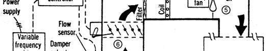
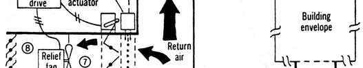
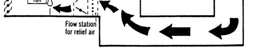
37 Fig. 6-6 >>
ASHRAE JOURNAL ON REHEAT
 Page: 1 of 7 ASHRAE JOURNAL ON REHEAT Dan Int-Hout Chief Engineer Page: 2 of 7 Overhead Heating: A lost art. March 2007 ASHRAE Journal Article Dan Int-Hout Chief Engineer, Krueger VAV terminals provide
Engineering Guide VAV Diffusers. Please refer to the Price Engineer s HVAC Handbook for more information on VAV Diffusers.
 VAV Diffusers lease refer to the rice Engineer s HVAC Handbook for more information on VAV Diffusers. Diffuser Types Ceiling Diffusers Conventional air distribution systems typically group several rooms
For an ideal gas mixture, Dalton s law states that the sum of the partial pressures of the individual components is equal to the total pressure.
 1 PSYCHROMETICS Psychrometry is the study of the characteristics of moist air. We will see soon that evaporation of moisture from the skin can have a significant impact on thermal comfort. The rate of
Dehumidifying with Dedicated Outdoor Air
 Dehumidifying with Dedicated Outdoor Air System Configurations Figure 71. Configurations for dedicated outdoor-air systems A dedicated outdoor-air handler separately filters, cools, dehumidifies, heats,
CHAPTER 4. HVAC DELIVERY SYSTEMS
 CHAPTER 4. HVAC DELIVERY SYSTEMS 4.1 Introduction 4.2 Centralized System versus Individual System 4.3 Heat Transfer Fluids 4.4 CAV versus VAV Systems 4.5 Common Systems for Heating and Cooling 4.6 Economizer
SYNOPSIS. Part-Load Control Strategies for Packaged Rooftop Units. In this issue... Bin Hour Profile Charlotte, NC
 VOLUME ONE NUMBER THREE SYNOPSIS A N H V A C N E W S L E T T E R F O R B U I L D I N G O W N E R S A N D M A N A G E R S In this issue... Part-Load Strategies Why they re important.......... 1 What Things
Air Conditioning Clinic
 Air Conditioning Clinic VAV Systems One of the Systems Series July 2012 TRG-TRC014-EN VAV Systems One of the Systems Series A publication of Trane Preface VAV Systems A Trane Air Conditioning Clinic Figure
HVAC DISTRIBUTION and DELIVERY SYSTEMS
 HVAC DISTRIBUTION and DELIVERY SYSTEMS (Part 1) Ball State Architecture ENVIRONMENTAL SYSTEMS 2 Grondzik 1 REMINDER HVAC = Heating, Ventilating, Air-Conditioning The AC part of HVAC implies a system that
Air Conditioning Clinic
 Air Conditioning Clinic Psychrometry One of the Fundamental Series D C B A C B D A July 2012 TRG-TRC001-EN Psychrometry One of the Fundamental Series A publication of Trane Preface Psychrometry A Trane
HAP e-help. Modeling Induction Beams in HAP v4.8 QB TIP 001
 This HAP e-help provides a high-level overview of induction beams, how they work and how to model them in HAP 4.8 (and later versions). The first half of the article explains how induction beams work.
Adding More Fan Power Can Be a Good Thing
 This article was published in ASHE Journal, May 14. Copyright 14 ASHE. Posted at www.ashrae.org. This article may not be copied and/or distributed electronically or in paper form without permission of
Temperature Control and Zoning of UFAD Systems
 Temperature Control and Zoning of UFAD Systems Presented by TROX USA Raised access flooring systems have become a very popular conduit for the delivery of power, voice and data services, as their accessibility
ME 410 MECHANICAL ENGINEERING SYSTEMS LABORATORY MASS & ENERGY BALANCES IN PSYCHROMETRIC PROCESSES EXPERIMENT 3
 ME 410 MECHANICAL ENGINEERING SYSTEMS LABORATORY MASS & ENERGY BALANCES IN PSYCHROMETRIC PROCESSES EXPERIMENT 3 1. OBJECTIVE The objective of this experiment is to observe four basic psychrometric processes
UNIVERSITY OF MISSOURI Heating Ventilating and Air-Conditioning (HVAC) 2016 Q1
 2016 Q1") GENERAL: This section provides general standards for overall sizing and design of Heating, Ventilating, and Air Conditioning (HVAC) systems. Other sections contain specific standards for each system per
GENERAL: This section provides general standards for overall sizing and design of Heating, Ventilating, and Air Conditioning (HVAC) systems. Other sections contain specific standards for each system per
product application data PERFECT HUMIDITY DEHUMIDIFICATION SYSTEM
 product application data PERFECT HUMIDITY DEHUMIDIFICATION SYSTEM 551B 581B DuraPac Plus Series Sizes 036-150 3to12 1 / 2 Tons Cancels: New PAD 551B.36.2 10/1/04 CONTENTS Page INTRODUCTION.................................
CARRIER edesign SUITE NEWS. Modeling 100% OA Constant Volume Air Systems. Volume 6, Issue 1. Page 1 Modeling 100% OA Constant Volume Air Systems
 Volume 6, Issue 1 CARRIER edesign SUITE NEWS Modeling 100% OA Constant Volume Air Systems This article provides an overview of how to model a stand-alone constant air volume (CAV) 100% OA system in HAP.
UFAD and Displacement Ventilation. Dan Int-Hout, FASHRAE Chief Engineer Krueger Richardson, Texas
 UFAD and Displacement Ventilation Dan Int-Hout, FASHRAE Chief Engineer Krueger Richardson, Texas UFAD and DV Systems, Objectives: Understand Differences between: Well Mixed, Partially Stratified and Fully
Introduction to HVAC. American Standard Inc Air Conditioning Clinic TRG-TRC018-EN
 Introduction to HVAC Agenda Psychrometrics Human Comfort Heat Transfer Refrigeration Cycle HVAC Terminology HVAC Systems Introduction to HVAC Psychrometrics 2000 TRG-TRC002-EN Properties of Air Dry-bulb
AIR-CONDITIONING SYSTEMS AND APPLICATIONS. Abdullah Nuhait Ph D. King Saud University
 AIR-CONDITIONING SYSTEMS AND APPLICATIONS Abdullah Nuhait Ph D. King Saud University AIR-CONDITIONING SYSTEMS Earliest air conditioning system used only for heating (winter) Provided heated air for comfort
Appendix 13. Categories of Cooling and Heating systems
 EcoShopping - Energy efficient & Cost competitive retrofitting solutions for Shopping buildings Co-funded by the European Commission within the 7 th Framework Programme. Grant Agreement no: 609180. 2013-09-01
Modular Active. Chilled. Beams
 Modular Active Chilled Beams How Twa MAC Beams Work Primary air (100% outside air) is dehumidified to between 50-57 F dew point and is used to: control the latent requirements of the space, provide fresh
BOOK 1 OVERVIEW RD2XRT INSTALLATION AND OPERATION MANUAL. Table of Contents ABOUT BOOK 1:
 4510 Helgesen Drive, Madison, WI, 53718 608.221.4499, 800.627.4499, Fax: 608.221.2824 support@renewaire.com www.renewaire.com RD2XRT INSTALLATION AND OPERATION MANUAL BOOK 1 OVERVIEW ABOUT BOOK 1: This
CARRIER edesign SUITE NEWS. Interpreting High (Low) Peak Design Airflow Sizing Results for HVAC. Equipment Selection.
 Peak Design Airflow Sizing Results for HVAC. Equipment Selection.") Volume 5, Issue 1 CARRIER edesign SUITE NEWS Interpreting High (Low) Peak Design Airflow Sizing Results for HVAC Equipment Selection A design challenge sometimes occurs when computing design loads using
Volume 5, Issue 1 CARRIER edesign SUITE NEWS Interpreting High (Low) Peak Design Airflow Sizing Results for HVAC Equipment Selection A design challenge sometimes occurs when computing design loads using
August 15, 2013 Page 1 of 19
 Section C401 Application Compliance with C402, C403, C404 and C405 AND (either C406.2, C406.3 or C406.4) Compliance with C402, C403, C404 or C405 Section C402 Building Envelope (Climate Zone 5A) Space-Conditioning
Comfort and health-indoor air quality
 Comfort and health-indoor air quality 1 The human body has a complicated regulating system to maintain the human body temperature constant most of the time, which is 98.6 F (36.9 C) regardless of the environmental
Don t Turn Active Beams Into Expensive Diffusers
 This article was published in ASHRAE Journal, April 2012. Copyright 2012 American Society of Heating, Refrigerating and Air-Conditioning Engineers, Inc. Posted at www.ashrae.org. This article may not be
BOOK 1 OVERVIEW RD2XIN INSTALLATION AND OPERATION MANUAL. Table of Contents ABOUT BOOK 1:
 4510 Helgesen Drive, Madison, WI, 53718 608.221.4499, 800.627.4499, Fax: 608.221.2824 support@renewaire.com www.renewaire.com RD2XIN INSTALLATION AND OPERATION MANUAL BOOK 1 OVERVIEW ABOUT BOOK 1: This
Benefits Offered by Passive Dehumidification Wheel Speed Control
 Benefits Offered by Passive Dehumidification Wheel Speed Control White paper By John Fischer Benefits Offered by Passive Dehumidification Wheel Speed Control The most significant advantage of the Pinnacle
ME 410 MECHA ICAL E GI EERI G SYSTEMS LABORATORY
 ME 410 MECHA ICAL E GI EERI G SYSTEMS LABORATORY MASS & E ERGY BALA CES I PSYCHROMETRIC PROCESSES EXPERIME T 3 1. OBJECTIVE The object of this experiment is to observe four basic psychrometric processes
PINNACLE SERIES DEDICATED OUTDOOR AIR SYSTEM ENERGY EFFICIENT DEHUMIDIFICATION
 ENERGY EFFICIENT DEHUMIDIFICATION PINNACLE SERIES DEDICATED OUTDOOR AIR SYSTEM Provides a very high degree of latent cooling using only a minimal amount of conventional cooling input Substantial energy
INTRODUCTION HVAC BASICS AND HVAC SYSTEM EFFICIENCY IMPROVEMENT SECTION O 4/19/2012
 HVAC BASICS AND HVAC SYSTEM EFFICIENCY IMPROVEMENT SECTION O INTRODUCTION HVAC systems or Heating, Ventilating and Air-Conditioning systems control the environment for people and equipment in our facilities.
Design Options For HVAC Distribution System. Course Content
 Design Options For HVAC Distribution System Course Content CENTRAL HVAC SYSTEM AN OVERVIEW The objective of an HVAC (heating, ventilating, and air-conditioning) system is to control the temperature, humidity,
Topic 2. ME 414/514 HVAC Systems Overview Topic 2. Equipment. Outline
 ME 414/514 HVAC Systems Overview Equipment Outline 2-1 The Complete System 2-2 The Air-Conditioning and Distribution System 2-3 Mechanical Equipment Air-handling Equipment Heating Equipment Boilers Furnaces
Relative Humidity in Schools Jim Cummings and Chuck Withers
 to Co n tr o l Relative Humidity in Schools Jim Cummings and Chuck Withers SEEC Southern Energy-Efficiency Center Energy Efficient Strategies to Control Relative Humidity in Schools James Cummings and
City of Duluth Festival Center 04/25
 SECTION 230593 - TESTING, ADJUSTING, AND BALANCING FOR HVAC PART 1 - GENERAL 1.1 RELATED DOCUMENTS A. Drawings and general provisions of the Contract, including General and Supplementary Conditions and
REPRODUCTION/DISTRIBUTION IS PROHIBITED. Energy-Savings Strategies for. Rooftop
 Energy-Savings Strategies for Rooftop VAV Systems Occupied set-point temperature Unoccupied set-point temperature Rooftop variable-air-volume (VAV) s are used to provide comfort in a wide range of building
DADANCO Technical Paper
 DADANCO Technical Paper 260 North Elm Street Westfield, MA 01085 Phone: (413) 564-5657 Fax: (413) 568-2969 March 2013 CLASSROOM SOLUTION USING ACTIVE CHILLED BEAMS (Note: This technical paper assumes the
Heat pump and energy recovery systems
 SBS5311 HVACR II http://ibse.hk/sbs5311/ Heat pump and energy recovery systems Ir. Dr. Sam C. M. Hui Faculty of Science and Technology E-mail: cmhui@vtc.edu.hk Oct 2017 Contents Basic concepts Air-to-air
b.) Technical Information:
 Technical Information:") Section VI- Strategies a.) Summary: It is important for new construction designers to consider the heating, ventilation, and air conditioning needs within a building. There are many different systems,
Section VI- Strategies a.) Summary: It is important for new construction designers to consider the heating, ventilation, and air conditioning needs within a building. There are many different systems,
OSU Alumni Center Phase I Implementation Review. Oregon State University 130 Oak Creek Bldg. Corvallis, Oregon
 OSU Alumni Center Phase I Implementation Review Prepared for Oregon State University 130 Oak Creek Bldg. Corvallis, Oregon 97331 October 31, 2011 Job No. 02.11.00113 Introduction: Glumac was engaged by
AND AIR-CONDITIONING. Dr Ali Jawarneh Department of Mechanical Engineering Hashemite University
 Chapter 14 GAS VAPOR MIXTURES AND AIR-CONDITIONING Dr Ali Jawarneh Department of Mechanical Engineering Hashemite University 2 Objectives Differentiate between dry air and atmospheric air. Define and calculate
Fan Selection. and Energy Savings
 Fan Selection and Energy Savings Reducing power consumption by minimizing system pressure loss and choosing the right equipment HBy BRIAN MLEZIVA Greenheck Fan Corp. Schofield, Wis. Power Consumption HVAC
Effects of Kitchen Ventilation on Residential Dwellings
 Effects of Kitchen Ventilation on Residential Dwellings Anthony C. Jellen Engineering i Projects Incorporated 1 Personal Background U.S.N. (1994 2000) BS B.S. in Civil Engineering (2005) PHRC employee
Mechanical System Redesign. Dedicated Outdoor Air System. Design Criteria
 Mechanical System Redesign Dedicated Outdoor Air System Design Criteria The outdoor air conditions used were for Philadelphia, Pennsylvania IAP at a 0.4% occurrence. The supply air conditions were developed
ENGINEERING BULLETIN. Overview of Chilled Beam Technology. Purpose. Summary. Theory
 Overview of Chilled Beam Technology Purpose Chilled beam technology is new to the United States but has been used in Europe since the 1950 s. Chilled beams can reduce energy costs, improve indoor air quality,
Retrocommissioning Findings Summary: Building X #1 Priority: Major Comfort/Control Problems
 IMPORTANT NOTICE: This sample document is provided for instructional purposes only. CCC is not rendering advice concerning any commission project or practices. This document is neither approved nor intended
Pharmaceutical Facility Design
 PhEn-602 Pharmaceutical Facility Design J. Manfredi Notes 9A PhEn-602 J. Manfredi 1 Primary & Secondary HVAC units Primary Primary air handling unit arrangement: One unit is responsible for all of the
Union County Vocational - Technical Schools Scotch Plains, New Jersey
 SECTION 230593 - TESTING, ADJUSTING, AND BALANCING FOR HVAC PART 1 - GENERAL 1.1 SUMMARY A. Section Includes: 1. Balancing Air Systems: a. Constant-volume air systems. b. Variable-air-volume systems. 2.
THE PSYCHROMETRIC CALCULATOR By: Stanley F. Gallos, The Bastian-Blessing Company INTRODUCTION PROPERTIES OF THE RSES CALCULATOR
 Source Application Manual SAM Chapter 620-20 Section 03 THE PSYCHROMETRIC CALCULATOR By: Stanley F. Gallos, The Bastian-Blessing Company INTRODUCTION Problems involving changes in temperature, humidity,
Capt. Tim s s Duct Design Mythbusters. The bitterness of poor quality is remembered long after the sweetness of low price is forgotten!
 Capt. Tim s s Duct Design Mythbusters The bitterness of poor quality is remembered long after the sweetness of low price is forgotten! WHY CARE ABOUT THE DUCTS? Human Comfort Zone (After All, it s s only
Designing Energy Efficient Outdoor Air Systems
 Designing Energy Efficient Outdoor Air Systems Joseph Thorndal Applied Products Sales Manager Greenheck, Schofield, Wisconsin 1 Joseph Thorndal BS Industrial Engineering North Dakota State University Work
HVAC Optimization with Cold Air Distribution
 PDHonline Course M186 (2 PDH) HVAC Optimization with Cold Air Distribution Instructor: A. Bhatia, B.E. 2012 PDH Online PDH Center 5272 Meadow Estates Drive Fairfax, VA 22030-6658 Phone & Fax: 703-988-0088
Chapter 14 GAS VAPOR MIXTURES AND AIR-CONDITIONING
 Thermodynamics: An Engineering Approach, 6 th Edition Yunus A. Cengel, Michael A. Boles McGraw-Hill, 2008 Chapter 14 GAS VAPOR MIXTURES AND AIR-CONDITIONING Mehmet Kanoglu Copyright The McGraw-Hill Companies,
4. OVERVIEW OF MECHANICAL SYSTEM
 4. OVERVIEW OF MECHANICAL SYSTEM The 87,000 SF SLCC is served by six (6) Trane M-Series Climate Changer Air Handing Units (AHUs). Each unit serves a distinct zone within the facility that is unique in
PRESSURE-ENTHALPY CHARTS AND THEIR USE By: Dr. Ralph C. Downing E.I. du Pont de Nemours & Co., Inc. Freon Products Division
 INTRODUCTION PRESSURE-ENTHALPY CHARTS AND THEIR USE The refrigerant in a refrigeration system, regardless of type, is present in two different states. It is present as liquid and as vapor (or gas). During
Selection of air conditioning systems
 Selection of air conditioning systems Prof. M. Ramgopal Department of Mechanical Engineering IIT Kharagpur Objectives 1. List the criteria used in the selection of air conditioning systems 2. List typical
100% Outdoor Air Dehumidification Methods
 Technical Bulletin 16 100% Outdoor Air ehumidification Methods I NTROUCTION As consulting engineers and end users implement the ASHRAE 6 ventilation code, they are faced with selecting an appropriate method
DESIGNING MODULAR VAV SYSTEMS
 FORM 5.2 REV 0905 THERMA-FUSER THERMALLY POWERED VAV DIFFUSER DESIGNING MODULAR VAV SYSTEMS MODULAR VAV SYSTEMS The Therma-Fuser diffuser is a simple stand alone device that provides VAV control when supplied
DEHUMIDIFICATION: Ice Arena Application & Product Guide. Design, construct and operate to control indoor humidity in ice rinks
 DEHUMIDIFICATION: Ice Arena Application & Product Guide Design, construct and operate to control indoor humidity in ice rinks Munters is the world leader in dehumidification Munters is the largest manufacturer
ASHRAE Region VI CRC Track III: Session 3 Ventilation Energy Recovery. Steven T. Taylor, PE Principal Taylor Engineering
 ASHRAE Region VI CRC Track III: Session 3 Ventilation Energy Recovery Steven T. Taylor, PE Principal Taylor Engineering This program is registered with the AIA/CES for continuing professional education.
Thermodynamics II Chapter 6 Mixtures & Psychrometry
 Thermodynamics II Chapter 6 Mixtures & Psychrometry Mohsin Mohd Sies Fakulti Kejuruteraan Mekanikal, Universiti Teknologi Malaysia Objectives Differentiate between dry air and atmospheric air. Define and
4-Pipe VAV vs. Active Chilled Beams for Labs
 Steven T. Taylor 4-Pipe VAV vs. Active Chilled Beams for Labs BY STEVEN T. TAYLOR, P.E., FELLOW ASHRAE Variable air volume (VAV) laboratory HVAC systems, including VAV fume hoods, are now standard practice
IDL20e (2 way discharge) IDS60e (4 way discharge) Inffusers. UDI (vertical discharge) Frequently Asked Questions
 IDS60e (4 way discharge) Inffusers. UDI (vertical discharge) Frequently Asked Questions") IDL20e (2 way discharge) IDS60e ( way discharge) Frequently Asked Questions UDI (vertical discharge) Inffusers INFFUSER FREQUENTLY ASKED QUESTIONS The following are frequently asked questions (FAQ s) on
IDL20e (2 way discharge) IDS60e ( way discharge) Frequently Asked Questions UDI (vertical discharge) Inffusers INFFUSER FREQUENTLY ASKED QUESTIONS The following are frequently asked questions (FAQ s) on
Energy-Efficient Makeup Air Units BY HUGH CROWTHER, P.ENG., MEMBER ASHRAE
 This article was published in ASHRAE Journal, March 20145 Copyright 2015 ASHRAE. Posted at www.ashrae.org. This article may not be copied and/or distributed electronically or in paper form without permission
ENGINEERING. Edition No. 13 October 2002
 Edition No. 13 October 2002 ENGINEERING S Y S T E M S O L U T I O N S W e at McQuay are very proud of our tradition of producing industry leading water source heat pumps. Our heritage stretches back more
Verasys System Operation Overview Technical Bulletin
 Contents subject to change. Verasys System Operation Overview Technical Bulletin Code No. LIT-12012370 Issued January 2016 Refer to the QuickLIT Web site for the most up-to-date version of this document.
HVAC Design Overview of Variable Air Volume Systems
 PDHonline Course M252 (4 PDH) HVAC Design Overview of Variable Air Volume Systems Instructor: A. Bhatia, B.E. 2012 PDH Online PDH Center 5272 Meadow Estates Drive Fairfax, VA 22030-6658 Phone & Fax: 703-988-0088
Chilled beams. TRACE 700 incorporates two chilled beam strategies: passive and active.
 TRACE 700 incorporates two chilled beam strategies: passive and active. Passive chilled beams consist of a fin-and-tube cooling coil, contained in a housing (or casing), suspended from the ceiling. Chilled
Do All DOAS Configurations Provide the Same Benefits?
 TECHNIL FTURE This article was published in ASHE Journal, July 2014. Copyright 2014 ASHE. Posted at www.ashrae.org. This article may not be copied and/or distributed electronically or in paper form without
HVAC Mandatory Provisions Part II, Page 1
 HVAC Mandatory Provisions Part II, Page 1 Mandatory Equipment Efficiency Worksheet (6.4.1.1) System Equipment Type Size Category (Tables 6.8.1A through K) Sub-Category or Rating Condition Units of Efficiency
Feasibility of a Liquid Desiccant Application in an Evaporative. Cooling Assisted 100% Outdoor Air System
 Feasibility of a Liquid Desiccant Application in an Evaporative Cooling Assisted 100% Outdoor Air System M.H.Kim 1, S.K.Han 1, S.Y. Cho 2, and J.W.Jeong 1* 1 Department of Architectural Engineering, Hanyang
Air Conditioning Clinic. Absorption Water Chillers One of the Equipment Series TRG-TRC011-EN
 Air Conditioning Clinic Absorption Water Chillers One of the Equipment Series TRG-TRC011-EN Absorption Water Chillers One of the Equipment Series A publication of The Trane Company Worldwide Applied Systems
INTRODUCTION TO: ASHRAE STANDARD 90.1, HVAC System Requirements for Reducing Energy Consumption in Commercial Buildings
 INTRODUCTION TO: ASHRAE STANDARD 90.1, 2013 HVAC System Requirements for Reducing Energy Consumption in Commercial Buildings Rocky Mountain ASHRAE Technical Conference, April 29, 2016 SEAN BEILMAN, P.E.,
SESSION Michigan Energy Code (MEC) Update (3 Technical) Per SMACNA Standard (TAB, Duct Design) and ASHRAE ( ) ASHRAE Detroit Members:
 Update (3 Technical) Per SMACNA Standard (TAB, Duct Design) and ASHRAE ( ) ASHRAE Detroit Members:") SESSION 1-2015 Michigan Energy Code (MEC) Update (3 Technical) Per SMACNA Standard (TAB, Duct Design) and ASHRAE (90.1.2013) ASHRAE Detroit Members: AM Session is eligible for (X) Professional Development
SESSION 1-2015 Michigan Energy Code (MEC) Update (3 Technical) Per SMACNA Standard (TAB, Duct Design) and ASHRAE (90.1.2013) ASHRAE Detroit Members: AM Session is eligible for (X) Professional Development
Humidity Control Systems for Civil Buildings in Hot Summer and Cold. Winter Zone in China
 Humidity Control Systems for Civil Buildings in Hot Summer and Cold Winter Zone in China Xiaoping Yu Doctoral Candidate Chongqing University of Science & Technology Chongqing, China, 400042 xiaoyup@163.com
Feasibility of Controlling Heat and Enthalpy Wheel Effectiveness to Achieve Optimal Closed DOAS Operation
 Purdue University Purdue e-pubs International Refrigeration and Air Conditioning Conference School of Mechanical Engineering July 2018 Feasibility of Controlling Heat and Enthalpy Wheel Effectiveness to
Zoned Rooftop Systems. Light commercial packaged rooftop systems from Trane
 Zoned Rooftop Systems Light commercial packaged rooftop systems from Trane Trane Zoned Rooftop Systems Components of Trane Zoned Rooftop Systems p. 3 Zoned Rooftop System Configurations p. 4 Systems comparison
Energy Recovery Ventilation
 Published on Business Energy Advisor (https://oncor.bizenergyadvisor.com) Home > Energy Recovery Ventilation Energy Recovery Ventilation Proper ventilation is essential for maintaining good indoor-air
SECTION SEQUENCE OF OPERATIONS FOR HVAC CONTROLS
 SECTION 23 09 93 SEQUENCE OF OPERATIONS FOR HVAC CONTROLS PART 1 - GENERAL 1.1 SUMMARY A. This Section includes control sequences for HVAC systems, subsystems, and equipment. B. See Division 23 Section
Single Zone System. One duct system Used mostly in small buildings Forced air system All spaces controlled by a single thermostat Single air return
 Single Zone System One duct system Used mostly in small buildings Forced air system All spaces controlled by a single thermostat Single air return Multi Zone System Used in small to medium sized buildings
D-PAC. Digital Precise Air Control System. Functionality Factory Testing Ease of Installation Ease of Maintenance Energy Efficiency
 Digital Precise Air Control System D-PAC Functionality Factory Testing Ease of Installation Ease of Maintenance Energy Efficiency AAON 24 South Yukon Avenue Tulsa, Oklahoma 747 (918) 583-2266 Fax (918)
2009 IECC Commercial Mechanical Requirements
 BUILDING ENERGY CODES UNIVERSITY 2009 IECC Commercial Mechanical Requirements Ken Baker PNNL-SA-66171 Learning(Objec-ves(( ( 1. Find(minimum(equipment(efficiency(requirements( and(recite(at(least(3(common(terms(for(measuring(
terminal units only provide sensible cooling, a separate dehumidification system is usually needed.
 providing insights for today s hvac system designer Engineers Newsletter volume 44 3 Dual-Temperature Chiller Plants This Engineers Newsletter describes several dual-temperature configurations that can
Fan Laws. Keith Miller. Samuel Tepp Associates. Paul Cenci, P. E.-Principal Brian England-Principal. Samuel Tepp Associates 1/6/10
 Fan Laws Keith Miller Samuel Tepp Associates Paul Cenci, P. E.-Principal Brian England-Principal Basic Terms CFM - Cubic Feet per Minute, volume (amount) of air being moved SP - Static Pressure, resistance
2. CURRICULUM. Sl. No.
 . CURRICULUM Sl. No. Code Title No. of Lecture Hours 1 RAC 001 Fundamentals of Refrigeration and Air 60 conditioning RAC 00 Psychrometry, Heat load Estimation for 70 Air conditioning and Refrigeration
System Components with ` Emphasis on Packaged Rooftop Application and Installation. Jerry Cohen President Jacco & Assoc.
 System Components with ` Emphasis on Packaged Rooftop Application and Installation Jerry Cohen President Jacco & Assoc. Agenda Define and relate in practical terms the following components: System Effect
HVAC (Heating, Ventilating, and Air Conditioning)
") HVAC (Heating, Ventilating, and Air Conditioning) Gas vapor Mixtures The term vapor implies a gaseous state that is close to the saturation region of the substance, raising the possibility of condensation
HVAC (Heating, Ventilating, and Air Conditioning) Gas vapor Mixtures The term vapor implies a gaseous state that is close to the saturation region of the substance, raising the possibility of condensation
Job Name Control Systems Description Date
 Job Name Control Systems Description Date Project Overview The project is a describe the building and its major HVAC systems (e.g. three-story office building, served by a rooftop unit VAV system ). In
ASHRAE WILL GIVE YOU THE WORLD. This ASHRAE Distinguished Lecturer is brought to you by the Society Chapter Technology Transfer Committee
 ASHRAE WILL GIVE YOU THE WORLD This ASHRAE Distinguished Lecturer is brought to you by the Society Chapter Technology Transfer Committee Complete the Distinguished Lecturer Event Summary Critique CTTC
RSES Technical Institute Training Manual 3 72 hours, 72 NATE CEHs, 7.2 CEUs
 Lesson 1 - Basic Heat Pump Theory (Part 1) Describe the basic operation of a heat pump. Explain the function of various heat pump controls. Interpret the wiring diagrams and performance data provided by
Displacement Ventilation
 Displacement Ventilation Displacement Ventilation Displacement Ventilation vs. Dilution Ventilation Characteristics Design Considerations Layout and Selection Product Overview Casino Case Study Dilution
S.A. Klein and G.F. Nellis Cambridge University Press, 2011
 12.A-1 A mixture of helium and water vapor is flowing through a pipe at T= 90 C and P = 150 kpa. The mole fraction of helium is y He = 0.80. a.) What is the relative humidity of the mixture? b.) What is
A. Base Bid: 1. Heating Contractor provide: a. Control sequences for HVAC systems, subsystems, and equipment.
 SECTION 23 09 93 - SEQUENCE OF OPERATIONS FOR HVAC CONTROLS PART 1 - GENERAL 1 WORK INCLUDES A. Base Bid: Heating Contractor provide: Control sequences for HVAC systems, subsystems, and equipment. B. Alternate
SPACE CONDITIONING IN COMMERCIAL BUILDINGS Overview
 SPACE CONDITIONING IN COMMERCIAL BUILDINGS Overview As in residential buildings the purpose of mechanical conditioning and ventilation is to maintain air quality and thermal comfort in buildings, with
design brief This design brief provides an introduction into the design and application of DV. It addresses the following issues:
 energydesignresources design brief DISPLACEMENT VENTILATION Summary Displacement ventilation (DV) is an alternate air distribution method for commercial and industrial spaces. 1 Used since the late 1970s
College of Technological Studies Department of Power & Refrigeration Technology. Course Contents
 College of Technological Studies Department of Power & Refrigeration Technology Course Contents Course Designation: Air Conditioning Control systems Course No. : 272 0463 Credit Hrs.: 3 Lecture Hrs.: 2
Design Considerations For Dedicated OA Systems BY HUGH CROWTHER, P.ENG, MEMBER ASHRAE; YI TENG MA, ASSOCIATE MEMBER ASHRAE
 ASHRAE www.ashrae.org. Used with permission from ASHRAE Journal. This article may not be copied nor distributed in either paper or digital form without ASHRAE s permission. For more information about ASHRAE,
ENGINEERING LETTER 4
 ENGINEERING LETTER 4 The New York Blower Company 7660 Quincy Street, Willowbrook, Illinois 60521-5530 TEMPERATURE AND ALTITUDE AFFECT FAN SELECTION INTRODUCTION Fan performance changes with the density
Technical college/ Baghdad 4th Year Week No. :- 11. The objectives of this lesson are to: Introduction:
 Refrigeration Systems Theoretical hours: 2 Practical hours: 2 Units: 6 COOLING TOWERS First 10 minutes: review the last lecture. Then explain the new lecture, solve an example. Last 10 minutes review the
COMPARING AIR COOLER RATINGS PART 1: Not All Rating Methods are Created Equal
 By Bruce I. Nelson, P.E., President, Colmac Coil Manufacturing, Inc. COMPARING AIR COOLER RATINGS PART 1: Not All Rating Methods are Created Equal Summary Refrigeration air coolers (evaporators) are widely