MICROCHANNEL HEAT EXCHANGERS WITH CARBON DIOXIDE
|
|
|
- Annabella Thomas
- 6 years ago
- Views:
Transcription
1 ARTI-21CR/12-1 MICROCHANNEL HEAT EXCHANGERS WITH CARBON DIOXIDE Final Report Date Published - September 21 Y. Zhao, M.M. Ohadi, R. Radermacher Center for Environmental Energy Engineering Department of Mechanical Engineering University of Maryland, College Park College Park, MD 2742 Prepared for the AIR-CONDITIONING AND REFRIGERATION TECHNOLOGY INSTITUTE 431 N. Fairfax Drive, Suite 425, Arlington, Virginia 2223 Distribution A - Approved for public release; further dissemination unlimited.
2 DISCLAIMER This report was prepared as an account of work sponsored by the Air-conditioning and Refrigeration Technology Institute (ARTI) under its HVAC&R Research for the 21St Century (21-CR) program. Neither ARTI, the financial supporters of the 21-CR program, or any agency thereof, nor any of their employees, contractors, subcontractors, or employees thereof, make any warranty, expressed or implied; assume any legal liability or responsibility for the accuracy, completeness, any third party s use of, or the results of such use of any information, apparatus, product, or process disclosed in this report, nor represent that its use would not infringe privately owned rights. Reference herein to any specific commercial product, process, or service by trade name, trademark, manufacturer, or otherwise, does not necessarily constitute nor imply its endorsement, recommendation, or favoring by ARTI, its sponsors, or any agency thereof, including their contractors or subcontractors. The views and opinions of the authors expressed herein do not necessarily state or reflect those of ARTI, the 21-CR program sponsors, or any agency thereof. Funding for the 21-CR program provided by (in order of support magnitude): - U.S. Department of Energy (DOE Cooperative Agreement No. DE-FC5-99R22674) - Air-conditioning and Refrigeration Institute (ARI) - Copper Development Association (CDA) - New York State Energy Research and Development Authority (NYSERDA) - Refrigeration Service Engineers Society (RSES) - Heating, Refrigeration, and Air-conditioning Institute of Canada (HRAI) Available to the public from: U.S. Department of Commerce National Technical Information Service 5285 Port Royal Road Springfield, VA (73) Available to The U.S. Department of Energy and its contractors in paper from: U.S. Department of Energy Office of Scientific and Technical Information P.O. Box 62 Oak Ridge, TN (423)
3 MICROCHANNEL HEAT EXCHANGERS WITH CARBON DIOXIDE Final Report Date Published - September 21 Y. Zhao M.M. Ohadi R. Radermacher Prepared for the AIR-CONDITIONING AND REFRIGERATION TECHNOLOGY INSTITUTE Under ART1 21-CR Program Contract Number 65-12
4 EXECUTIVE SUMMARY The objective of the present study was to determine the performance of C2 microchannel evaporators and gas coolers in operational conditions representing those of residential heat pumps. A set of breadboard prototype microchannel evaporators and gas coolers was developed and tested. The refrigerant in the heat exchangers followed a counter cross-flow path with respect to the airflow direction. The test conditions corresponded to the typical operating conditions of residential heat pumps. In addition, a second set of commercial microchannel evaporators and gas coolers was tested for a less comprehensive range of operating conditions. The test results were reduced and a comprehensive data analysis, including comparison with the previous studies in this field, was performed. Capacity and pressure drop of the evaporator and gas cooler for the range of parameters studied were analyzed and are documented in this report. A gas cooler performance prediction model based on non-dimensional parameters was also developed and results are discussed as well. In addition, in the present study, experiments were conducted to evaluate capacities and pressure drops for sub-critical C2 flow boiling and transcritical C2 gas cooling in microchannel heat exchangers. An extensive review of the literature failed to indicate any previous systematic study in this area, suggesting a lack of fundamental understanding of the phenomena and a lack of comprehensive data that would quantify the performance potential of C2 microchannel heat exchangers for the application at hand. All experimental tests were successfully conducted with an energy balance within +3%. The only exceptions to this were experiments at very low saturation temperatures i
5 (-23 "C), where energy balances were as high as 1%. In the case of evaporators, it was found that a lower saturation temperature (especially when moisture condensation occurs) improves the overall heat transfer coefficient significantly. However, under such conditions, air side pressure drop also increases when moisture condensation occurs. An increase in airflow rate also increases the overall heat transfer coefficient. Air side pressure drop mainly depends on airflow rate. For the gas cooler, a significant portion of the heat transfer occurred in the first heat exchanger module on the refrigerant inlet side. The temperature and pressure of C2 significantly affect the heat transfer and fluid flow characteristics due to some important properties (such as specific heat, density, and viscosity). In the transcritical region, performance of C2 strongly depends on the operating temperature and pressure. Semi-empirical models were developed for predictions of C2 evaporator and gas cooler system capacities. The evaporator model introduced two new factors to account for the effects of air-side moisture condensate and refrigerant outlet superheat. The model agreed with the experimental results within *13%. The gas cooler model, based on nondimensional parameters, successfully predicted the experimental results within +2%. Recommendations for future work on this project include redesigning headers and/or introducing flow mixers to avoid flow mal-distribution problems, devising new defrosting techniques, and improving numerical models. These recommendations are described in more detail at the end of this report. 11
6 ACKNOWLEDGMENTS This work was sponsored by the Air-conditioning and Refrigeration Technology Institute under ARTI 21-CR Program Contract Number The feedback and technical guidance of the project monitoring subgroup, including Michael Blanford, Karim Amrane, Piotr Domanski, Steve Memory, Michael Heidenreich, and Richard Cawley, is greatly acknowledged. We are also grateful to Glen Hourahan of ARTI for his feedback and many useful technical comments. The project manager was Mr. Michael Blanford, whose efforts in coordinating the various tasks of the project were invaluable. His continuous interactions with our team were critical for the successful completion of the project. We also would like to thank Dr. Yunho Hwang from our department who participated in many technical discussions and for his other contributions to the project
7 TABLE OF CONTENTS EXECUTIVE SUMMARY... i ACKNOWLEDGMENTS... iii TABLE OF CONTENTS... iv LIST OF TABLES... LIST OF FIGURES... NOMENCLATURE... CHAPTER 1. INTRODUCTION Phaseout of Refrigerants The Natural Refrigerants Carbon Dioxide as Working Fluid Benefits... 8 CHAPTER 2. RESEARCH BACKGROUND Previous C2 Heat Transfer Studies Previous Microchannel Heat Transfer Studies Recent Microchannel Experimental Work in Our Laboratory Microchannel Heat Exchangers for C CHAPTER 3. TEST FACILITIES AND SYSTEM COMPONENTS Indoor Loop Outdoor Duct Microchannel Heat Exchangers Evaporator Gas Cooler Refrigerant Loop Compressor Data Acquisition System vi vii x iv
8 3.7 Instrumentation and Measurements Pressure Measurements Air Stream Temperature Measurements Coriolis Mass Flow Meter Dew Point Temperature Measurement CHAPTER 4. EXPERIMENTAL RESULTS FOR MICRO-CHANNEL EVAPORATOR Experimental Test Conditions Experimental Test Results Data Reduction and Discussion Capacity Predictive Model for Microchannel Evaporators CHAPTER 5. EXPERIMENTAL RESULTS FOR MICRO-CHANNEL GAS COOLER Experimental Test Conditions Experimental Test Results Data Reduction and Discussion Models for Predicting the Capacity of a Gas Cooler CHAPTER 6. CONCLUSIONS AND PROPOSED FUTURE WORK Conclusions Future Works Two-Phase Flow Mal-distribution for a Microchannel Evaporator Defrosting Techniques Model Developments and Improvements Recommendations for Heat Exchanger Design APPENDIX A. DESIGN OF OBSTRUCTION FLOW METER REFERENCES V
9 LIST OF TABLES Table 1.1 Overview of selected natural refrigerants... 5 Table 1.2 Thermophysical properties of CO2 and R-134a at 5 / 1 / 15 "C... 7 Table 2.1 Summary of studies on single-phase flow in microchannels Table 2.2 Summary of studies on two-phase flow in microchannels Table 4.1 Experimental test conditions for evaporation (English Units) Table 4.2 Experimental test conditions for evaporation (SI Units)... 4 Table 4.3 Experimental data for evaporation (SI Units) Table 5.1 Experimental test conditions for gas cooler (English Units) Table 5.2 Experimental test conditions for gas cooler (SI Units) Table 5.3 Experimental data for gas cooling (SI Units) vi
10 LIST OF FIGURES Figure 2.1 Heat transfer coefficient of C2 and R- 134a Figure 2.2 Pressure drop of C2 and R-134a Figure 3.1 Schematic of indoor loop Figure 3.2 Air sampling tree Figure 3.3 Schematic of outdoor duct Figure 3.4 Energy balance for the calibrated obstruction flow meter Figure 3.5 Obstruction flow meter Figure 3.6 Microchannels from Hydro Aluminum Figure 3.7 Schematic of a microchannel unit slab Figure 3.8 Picture of a unit slab Figure 3.9 Picture of fins and microchannels Figure 3.1 Picture of header and stub Figure 3.11 Schematic of the evaporator stack layout... 3 Figure 3.12 Schematic of gas cooler layout Figure 3.13 Schematic of refrigerant loop Figure 3.14 A photograph of the Dorin semi-hermetic C2 compressor Figure 3.15 Screen shot of the data acquisition program written for the system Figure 3.16 Deviations between upstream average temperature and downstream average temperature Figure 4.1 Energy balance for evaporation test results Figure 4.2 Capacity of the evaporator vs. C2 mass flow rate (MFR) Figure 4.3 Overall heat transfer coefficient vs. air flow rate (AFR) vii
11 Figure 4.4 Ratio of latent heat to total heat of air side vs. air flow rate (AFR) Figure 4.5 Overall heat transfer coefficient vs. air flow rate (AFR) Figure 4.6 Ratio of latent heat to total heat of air side vs. air flow rate (AFR)... SO Figure 4.7 Pressure drop of air vs. air flow rate... SO Figure 4.8 Pressure drop of air vs. air flow rate Figure 4.9 Overall heat transfer coefficient vs. Cta Figure 4.1 Overall heat transfer coefficient vs. Bta Figure 4.11 Comparison between the model predictions and experimental results Figure 5.1 Energy balance for gas cooler test results Figure 5.2 Capacity vs. refrigerant mass flow rate Figure 5.3 Typical temperature profiles of air stream and refrigerant Figure 5.4 Typical heat transfer rate profile for each HX unit Figure 5.5 Percentage of heat transferred by each HX vs. refrigerant inlet pressure Figure 5.6 Specific heat of C2 vs. temperature Figure 5.7 Heat transfer effectiveness vs. number of HXs Figure 5.8 Heat transfer effectiveness vs. number of HXs for a C2 pressure of 7 MPa 7 Figure 5.9 Heat transfer effectiveness vs. number of HXs for Serial No. 1 condition Figure 5.1 Air side pressure drop as a function of air velocity Figure 5.11 Viscosity of C2 vs. temperature Figure 5.12 Density of C2 vs. temperature Figure 5.13 Predicted effectiveness vs. number of HX Figure 5.14 Predicted effectiveness vs. number of HX Figure 5.15 Comparison between the model predictions and experimental results Vlll
12 Figure 6.1 Schematic diagram of the proposed header design Figure A.l Schematic of outdoor air duct Figure A.2 Obstruction meter Figure A.3 Heat losses from the outdoor air duct Figure A.4 Flow coefficient as function of Reynolds number... 9 Figure A.5 Comparison between the heating determined by air and by heaters (Q = 2.2 kw) Figure A.6 Comparison between the heating determined by air and by heaters (Q = 1.5 kw) Figure A.7 Comparison between the heating determined by air and by heaters after correction Figure A.8 Results of energy balance Figure A.9 Volumetric flow rate vs. fan frequency ix
13 NOMENCLATURE A AFR Bta C surface area, m2 air flow rate, m3/h superheat related factor, Bta = specific heat, kj/kgk 'ref -out Tair-in-dry - 'ref -sat - Tref -sat Cta D Dh DP DT efs G h hfg j k K L moisture condensate factor, Cta = diameter, m hydraulic diameter, m pressure drop, kpa temperature difference, "C heat exchanger effectiveness mass flux, kg/m2s specific enthalpy, kjkg latent heat, kw/kg fin related coefficient thermal conductivity, W/mK flow coefficient length, m Tair-in-dew ' air-in-dry - Tref -sat m -' ref -sat LMTD log mean temperature difference m MFR NTU Nu P Pr Q Re mass flow rate, kg/s mass flow rate of refrigerant, gr/s number of exchanger heat transfer units Nusselt Number, (hd/k) pressure, kpa Prant Number rate of heat transfer, kw Reynolds Number, (GD/p) X
14 S specific entropy, kj/kgk St Stanton Number, Nu/(Re.Pr) T temperature, "C U overall heat transfer coefficient, W/m2K X Z vapor quality capacity rate ratio Greek Symbols P P viscosity, Pa.s Diameter ratio 6 fin spacing, m P density, kg/m3 Subscripts air ave cri dew dry face ideal in local out P ref RTD sat SUP total tp wet air stream average critical point dew point dry bulb face area of heat exchangers ideal conditions inlet local values outlet constant pressure refrigerant resistance temperature detector saturation superheat total heat transfer rate two phase wet bulb xi
15 CHAPTER 1 INTRODUCTION The objective of the present study was to determine the performance of C2 microchannel evaporators and gas coolers in operational conditions representing those of residential heat pumps. A set of breadboard prototype microchannel evaporators and gas coolers was developed and tested. The refrigerant in the heat exchangers followed a counter crossflow path with respect to the airflow direction. The test conditions corresponded to the typical operating conditions of residential heat pumps. Capacity and pressure drop of the evaporator and gas cooler for the range of parameters studied were analyzed and are documented in this report. Semi-empirical models wee also developed for prediction of C2 evaporator and gas cooler capacities. The experimental results are discussed in this report. This chapter presents an overview of natural refrigerants. 1.1 Phase-out of Refrigerants Refrigerants are the working fluids in refrigeration, air-conditioning, and heat pump systems. An "ideal" refrigerant is chemically stable and inert, has excellent thermal and fluid flow characteristics, is compatible with common materials, is soluble in lubricating oils, is nontoxic, nonflammable, has low cost, and is environmentally acceptable. Since no single fluid meets all these attributes, a variety of refrigerants have been developed and applied in HVAC&R systems. The Montreal Protocol is an international treaty that controls the production of ozone-depleting substances, including refrigerants containing chlorine and/or bromine 1
16 (U.N. 1994, 1996). The first version of the Protocol was signed September 16, 1987, by the European Economic Community (currently the European Union) and 24 nations, including the United States. As described in Chapter 18 of the ASHRAE Handbook of Fundamentals (21), the Montreal Protocol was enacted on January 1, 1989, and limits the 1998 production of specified carbofluorocarbons (CFCs) to 5% of their 1986 levels. Starting in 1992, the production of specified halons (including R-13B1) was frozen at 1986 levels. Developing countries were granted additional time to meet these deadlines. On June 14, 1994, the Copenhagen Amendment to the Montreal Protocol, ratified by 58 parties, was enacted. It called for a complete cessation of the production of CFCs by January 1, 1996, and of halons by January 1, Continued use from the existing (reclaimed or recycled) stock is permitted. Allowance is also provided for continued production for very limited "essential uses." In addition, hydrocarbofluorocarbons (HCFCs, including R-22) are to be phased out--according to a 1989 reference level for developed countries. Production was frozen at the reference level on January 1, Production will be limited to 65% of the reverence level by January 1, 24; to 35% by January 1, 21; to 1% by January 1, 215; and to.5% of the reference level by January 1, 22. Complete cessation of the production of HCFCs is called for by January 1, 23. In addition to the international agreement, individual countries may have domestic regulations for ozone-depleting compounds. The production and use of hydrofluorocarbon (HFC) refrigerants (such as R-32, R-125, R-l34a, and R-143a and their mixtures) are not regulated by the Montreal Protocol because they are not considered ozone depleting compounds. However, HFCs do have global warming potential because of their carbon content. Some individual 2
17 countries are beginning to regulate HFCs. Denmark, for example, is moving away from the use of HFC refrigerants. These facts indicate that the extensive use of synthetic refrigerants may be limited in the future and therefore should be used with caution. They also suggest that an alternative to HFC refrigerants could be useful if, in the future, these are phased out. 1.2 The Natural Refrigerants "Natural refrigerants" refer to those naturally occurring substances, such as air, ammonia, carbon dioxide, isobutane, propane, and water. An overview of selected natural refrigerants is provided in Table 1.1. Since these substances are naturally occurring in our atmosphere, the use of these substances is expected to have minimal adverse effects on the environment. The original application of natural refrigerants dates back to the middle of the nineteenth century when Linde, Perkins, Harrison, and others introduced pioneering refrigeration systems. In 1834, Perkins introduced the first refrigerant, sulfuric ether. From the 184s through 192s, the main refrigerants in practical use were ammonia ("3) for large and medium size stationary systems, sulfur dioxide (S2) for household refrigerators and small commercial plants, and carbon dioxide (C2) for ship installations, with brine as a secondary refrigerant. C2 was also often used in stationary systems (Elefsen et al., 1995). Midgley and Henne (193) published papers on fluorochemical refrigerants as a result of searching for stable, nontoxic, nonflammable, efficient refrigerants. In 1931, dichlorodifluoromethane, CFC- 12, was commercially produced (Downing, 1966). After 3
18 the introduction of fluorochemical refrigerants, the early refrigerants, including CO2, were replaced by many other CFCs, and later HCFCs. This course of action led to a drastic decline in the use of refrigerants other than CFCs and HCFCs after World War 11. Only ammonia remained in use, though it was predominantly used only in large industrial s ys tems. Ohadi and Mo (1998) conducted a detailed review of natural refrigerants. The role of natural refrigerants in preventing or mitigating the problems associated with global warming and ozone depletion was addressed. Thermophysical properties and cycle performance of selected natural refrigerants were discussed and compared with their counterpart HCFC and HFC refrigerants. It was concluded that while HFC blends have been able to address acceptable Ozone Depletion Potential (ODP), their Global Warming Potential (GWP) is high enough to warrant a continued search for environmentally friendly refrigerants. The use of natural refrigerants appears to be one solution to this problem for immediate, as well as future applications. Research work on natural refrigerants is receiving renewed attention. 4
19 Table 1.1 Overview of selected natural refrigerants Refrigerant General Characteristics Major Advantages Major Disadvantages Ammonia ("3) Ammonia is a well-known refrigerant in large scale industrial refrigeration plants. It has been used as a refrigerant for more than 12 years, but until now it has not been widely used in small plants. -More than 12 years of practical use -Excellent thermodynamic and thermophysical properties -Higher energy efficiency in most temperature ranges -Well known oil tolerance -Great tolerance to water contamination -Simple and immediate leak detection -No ODP or GWP -Lower cost -Smaller pipe dimensions leading to lower plant investments -Toxic at low concentrations in air (above 5ppm) -No tolerance to some materials, e.g. copper -No miscibility with most known oils -High discharge temperatures -Flammable at 153% VOl. Environmentally attractive, water has potential as a longterm acceptable refrigerant. Water offers high plant energy efficiency. -Higher Carnot COP due to the use of direct heat exchanger -High mechanical efficiency of compressor -Production of vacuum ice -Low energy consumption -No ODP or GWP -Process under vacuum -Good only for cooling/ refrigeration above C Carbon Dioxide (C2) In recent years, after the Montreal Protocol, much development activity has been devoted to C2 as a refrigerant. This development is based on new material technology which allows high pressures in the thermodynamic cycle. C2 is quite harmless; it is environmentally attractive, and is neither toxic, flammable nor explosive. -Low weight and small dimensions of plant -Large refrigeration capacity -Tolerance with well known oils -Low compression ratio -Low environmental impact -Low price, ample supply -High pressure -Low critical temperature (31 C) Hydrocarbons The measures taken to find suitable "natural" refrigerants as substitutes for CFC and HCFC have called attention to two hydrocarbons (propane and isobutane) that have properties similar to the most widely used CFCs and HCFCs. -Compatible with materials normally used in refrigeration plants, such as copper and mineral oil -Similar physical properties to CFC-12 (isobutane) and HCFC- 22 (propane) -Small amount of refrigerant needed -Lower prices than HFCs -Low environmental impact -Flammable at concentration of 1-1% v/v (requires additional safety measures) -Smaller volumetric cooling capacity 5
20 1.3 Carbon Dioxide as Working Fluid The development of refrigeration systems using C2 as a refrigerant dates back to 1866 when Thaddeus created an ice production machine using C2 (Thevenot, 1979). In 188, Windhausen designed the first C2 compressor (Gosman, 1927). After the late 18OOs, the use of C2 refrigeration systems increased. As a result of continuous efforts to improve efficiency, two-stage C2 machines were developed in 1889 in Great Britain (Thevnot, 1979). Later, the multiple-effect C2 cycle was developed by Voorhess in 195 (Thevenot, 1979). Although the use of C2 as a refrigerant declined drastically in the 193s due to the appearance of CFCs and HCFCs, C2 as a natural and environmentally favorable refrigerant has gained more attention recently. One of the solutions to minimize ozone depletion and global warming concerns is the use of natural refrigerants. Hydrofluorocarbons (HFCs) are replacement candidates, but have the disadvantages of relatively high GWP, high cost, and unresolved issues regarding environmental impact. Natural refrigerants, such as NH3 and C2, have a low GWP, no ODP, and no adverse environmental effects (Lorentzen, 1995). Its low toxicity, nonflammability, and low cost make C2 the preferred refrigerant when compared with "3. In addition to its environmental advantages, C2 offers certain attractive thermal characteristics. General physical and chemical properties of C2, as well as comparisons with those of other refrigerants, are listed in Chapter 18 of the ASHRAE Handbook of Fundamentals (1997). The thermophysical properties listed include the standard designation of characteristic properties, such as molecular mass, critical points, etc. Electrical properties, performance comparisons with other refrigerants, a safety 6
21 classification, and C2 s effect on several other materials are also provided. A brief chart and a saturated table of thermodynamic properties are given in Chapter 19 of the ASHRAE Handbook of Fundamentals (1997). As a refrigerant, C2 offers more variation in thermodynamic and transport properties than other conventional refrigerants, as mentioned by Devotta et al. (2). Since the critical temperature of C2 is 31 C for air-conditioning applications, the heat rejection above 31 C is not by condensation, as in conventional systems, which will necessarily lead to some changes in system design. Due to its higher volumetric capacity, which is five times higher than that of HCFC-22, the size of the system can be reduced considerably. Some important thermophysical properties of C2 and comparisons with R- 134a are listed in Table 1.2. Carbon dioxide has a much smaller surface tension and liquid viscosity than R- 134a. Lower surface tension facilitates bubble formation, thus resulting in higher heat transfer coefficients. Lower liquid viscosity causes a smaller pressure drop when C2 flows in a tube or channel. Table 1.2 Thermophysical properties of C2 and R-134a at 5 / 1 / 15 C I Refrigerant I co., I R-134a I Psat (MPa) Latent Heat (kj/kg) Liq. Density (kg/m ) Vap. Density (kg/m ) Liq. Viscosity (ppa.s) Vap. Viscosity (ppa.s) Liq. C, (kj/kg.k) Vap. C, (kj/kg.k) 3.969/4.52/5.OS 6.35/. 414/ /196.8/ /19.9/186.7 I Surface Tension (mn/m) I 3.53/2.67/1.88 I 11./1.3/9.6 I 899.6/861.5/ /126.2/ /13S.3/ /2.2/ /86.7/ /254.3/ /16.1/ /11.4/ /3.O U m.37/ /2.62/3.3.91/.93/.96 7
22 1.4 Benefits The research work preformed here will provide a design methodology platform for enhancedcompact heat exchangers for high pressure working fluids such as C2. The research results will have significant effects on the heat exchanger industries, from design and manufacturing/operation to integration in practical C2 systems. The findings in this study will contribute to the development and production of a new generation of high performance heat exchangers that are suitable for high pressure refrigerants such as C2, while offering significantly reduced size, weight, and consumed materials for the heat exchanger. A more in-depth understanding of the corresponding heat transfer and pressure drop phenomena and their empirical modeling is another inherent benefit of this research. 8
23 CHAPTER 2 RESEARCH BACKGROUND This chapter presents a brief review of the fundamentals of heat transfer in boiling and an extensive overview of the prior research efforts that have been conducted to investigate the heat transfer characteristics of pure refrigerant and refrigerantloil mixtures in smooth tubes, enhanced tubes, and microchannels. 2.1 Previous Studies on COZ Heat Transfer The open literature on C2 heat transfer is limited. Bredesen et al. (1997) investigated flow boiling of C2 in a smooth tube. The test section was a 7 mm-diameter aluminum tube with direct heating. Temperatures were measured at 1 different positions and the local heat transfer coefficient was calculated. Bredesen et al. found that C2 has a much higher heat transfer coefficient and much lower pressure drop than that experienced with halocarbons. In addition, their experimental results showed that as the heat flux was increased, the heat transfer coefficient increased considerably without pressure loss penalty. Moreover, high heat transfer coefficients could be obtained even with smaller mass flux and pressure drop. However, the explanation of this unexpected phenomenon was unconvincing in the paper. Based on the experimental results of Bredesen et al. (1997), Hwang et al. (1997) investigated the applicability of six commonly used empirical correlations reported by Chen (1966), Bennett-Chen (198), Gungor-Winston (1987), Shah (1976), Schrock- Grossman (1959), and Liu-Winteron (1991). It was found that the correlations had a large deviation (from 2% to 8%) when predicting the boiling heat transfer coefficient of C2. Hwang et al. proposed a new empirical model, the Modified Bennett-Chen 9
24 correlation, for C2 flow boiling in horizontal smooth tubes. They claimed that the new correlation could predict the heat transfer coefficients, consistent with Bredesen s results, to within a mean deviation of 14%. Zhao et al. (1997) studied the boiling heat transfer characteristics of ammonia and C2 in horizontal smooth tubes. The test section was a tube with an inner diameter of 5.44 mm and a length of 1.78 m. A water-heating method was applied, and the average heat transfer coefficient was determined. Zhao et al. reported a slightly smaller heat transfer coefficient compared to that of Bredesen et al. (1997). The deviation between the two results could be due to different thermal-boundary conditions, i.e. constant heat flux vs. the convection boundary condition, and different boiling temperatures. Their results, however, showed the same trend as Bredesen s data. They also compared the typical values of the heat transfer coefficient of C2 with those for R-l34a, R-12, and R-22, and found that the transfer coefficient of C2 is substantially higher. Olson and Allen (1998) investigated the heat transfer characteristics of supercritical C2 in turbulent flow in a heated horizontal tube. The tested tube was 1.9 mm ID and was heated over a length of 2.47 m. Operating pressure was varied from 7.8 MPa to 13.1 MPa. It was found that the measured Nusselt number agreed with the constant-property Petukhov-Gnielinski correlation for turbulent tube flow to within 6.6% at high operation pressure. As the pressure was reduced toward the critical pressure (7.38 MPa), the measured Nusselt number diverged from the constant-property correlation. At low pressures, the heat transfer coefficient increased with increasing mass flux and/or heat flux. 1
25 A review of the existing literature on C2 studies indicates that most of the C2 research studies conducted so far have been focused on heat exchanger design for heat pumps or refrigerators. This fact indicates that experimental investigation of the heat transfer coefficient and the modeling of C2 has received less attention. 2.2 Previous Studies on Microchannel Heat Transfer Heat transfer and fluid flow in microchannels have wide practical applications in highly specialized fields, such as bioengineering, microfabricated fluidic systems, and microelectronics. Lately, microchannels have been intensively used by the automotive air conditioning industry. The advantage of the microchannel lies in its high heat transfer coefficient and significant potential in decreasing the size of heat exchangers. Microchannels have almost completely replaced circular tubes in automotive condensers and have recently become the subject of study for automotive evaporators. Compared with channels of normal size, microchannels have many heat transfer advantages. Since microchannels have an increased heat transfer surface area and a large surface-to-volume ratio, they provide a much higher heat transfer. This feature allows heat exchangers to become compact and light-weight. In addition, microchannels can support high heat flux with small temperature gradients. However, microchannels also have weaknesses, such as large pressure drop, high cost of manufacture, dirt clogging, and flow mal-distribution, especially for two-phase flows. The hydraulic diameters of microchannels are quite small, typically 1 pm to 2 pm, and the fluid flow and heat transfer in microchannels are expected to be, in some cases, substantially different from those encountered in the normal-sized tubes and 11
26 channels. A review of microchannel heat transfer indicates that the previous studies can be divided into single-phase and two-phase (condensation and evaporation) forced convection. In two-phase flows, the studies are concentrated on heat transfer coefficient, pressure drop, and critical heat flux. Wang and Peng (1994), Peng and Wang (1994), and Peng et al. (1996, 1998) performed a series of tests on rectangular microchannels (with hydraulic diameters of mm) machined into stainless steel plates. They found that the flow transition for single-phase flow occurred at a Reynolds number (Re = pudh/p) of 2-7. This critical Re for the flow transition was strongly affected by the hydraulic diameter of the microchannel, and it decreased for smaller hydraulic diameters. In addition, the range of flow transition was diminished and the fully developed turbulent flow occurred at a much lower Re. For flow boiling in microchannels, the small size of the microchannel resulted in a dramatically higher heat flux for liquid nucleation when the microchannel was sufficiently small. However, microchannel size, flow velocity, and inlet sub-cooling temperature had no significant effect on the heat transfer coefficient in the fully nucleate boiling regime. Ravigururajan et al. (1996, 1998) studied the impact of size and geometry of microchannels on their heat transfer characteristics. For single-phase flow, they found that microchannels provided significantly higher heat transfer coefficients. They indicated that the higher heat-transfer coefficients might be attributed to the thinning of the boundary layer in the microchannels, although the use of microchannels increased the surface area significantly. They also found that parallel geometry microchannels could give a better heat transfer coefficient than diamond geometry microchannels. For flow 12
27 boiling, they inferred that the large number of channels per unit width (e.g. typically 25 or more channels per inch) results in a significantly higher heat transfer area. The twophase flow heat transfer coefficients strongly depend on the channel's geometry, surface, and shape. The heat transfer coefficient decreases with increasing saturation temperature, and the pressure drop increases with increasing heat flux. Tran et al. (1996) investigated laminar and turbulent boiling heat transfer in small circular and rectangular channels. They found that for wall superheats larger than 2.7S C, the nucleate boiling mechanism dominates the forced convection effect. Yang and Webb (1996) compared commonly used correlations with their experimental results. They found that Shah's (1979) correlation overpredicts the heat transfer coefficient, and that the correlation by Akers et al. (1959) is suitable for small mass fluxes. They also indicated that pressure drop increases with increasing mass flux and heat flux. Surface tension was found to play an important role in heat transfer. Bau (1998) numerically investigated the optimization of channel shape in micro heat exchangers. An approximate theory was derived to compute the thermal resistance of flat-plate micro heat exchangers whose surfaces are heated with uniform flux. It was demonstrated that the thermal resistance could be minimized by proper selection of uniform channel geometry. The maximum hot surface temperature and its gradient could be further reduced by changing the channel cross-sectional dimensions as a function of the axial coordinate. Tong et al. (1997) studied pressure drop with highly subcooled flow boiling in small-diameter tubes. In designing heat-removal systems utilizing high-heat-flux subcooled boiling, pressure drop is an important consideration. Tong et al. performed an 13
28 experimental investigation to identify the important parameters affecting pressure drop across small-diameter tubes in highly subcooled flow boiling. The effects of mass flux, inlet temperature, exit pressure, tube internal diameter, and length-to-diameter ratio on both single and two-phase pressure drop were studied and evaluated. The experimental results indicated that mass flux, tube diameter, and length-to-diameter ratio were the major parameters that altered the pressure-drop curves. Both single- and two-phase pressure drops increased with increasing mass flux and length-to-diameter ratio, but decreased with increasing internal diameter. Inlet temperature and exit pressure were shown to have a significant effect on two-phase pressure drop but a negligible effect on single-phase pressure drop. Tables 2.1 and 2.2 summarize the studies of fluid flow and heat transfer in microchannels. A review of the single-phase and two-phase heat transfer characteristics in microchannels indicates that the two-phase heat transfer in microchannels is superior to single-phase. As indicated by Bowers and Mudawar (1994), single-phase microchannel heat exchangers react to high surface heat fluxes by a large stream-wise increase in coolant temperature, and a corresponding stream-wise increase in the heat sink temperature. This temperature increase is often detrimental to temperature-sensitive devices, such as electronic components. Two-phase heat sinks, on the other hand, rely mainly on latent heat, and maintain a stream-wise uniform coolant and heat sink temperature at a level set by the coolant saturation temperature. To diminish the detrimental effect of a stream-wise temperature increase, microchannel heat sinks that operate in single-phase often need a large flow rate. Two-phase heat sinks, on the other hand, utilize the latent heat of liquid evaporation, and require minimal coolant flow rates. 14
29 However, since flow boiling has a critical heat flux, if the applied heat flux exceeds the critical heat flux, the dry-out phenomenon may occur. Under dry-out conditions, the heat transfer coefficient will be dramatically reduced, resulting in a rapid increase in wall temperature. Therefore, in two-phase microchannel heat sinks, a safety factor should be considered. 15
30 Table 2.1 Summary of studies on single-phase flow in microchannels Investigator Channel Geometry and Size (pm) Lancet Gap: 58 to 64 Gambill and Bundy, 1961 Wu and Little, 1983 Wu and Little, 1984 Acosta, 1985 Pfahler et al., 1991 Choi et al., 1991 Peng and Peterson, 1996 Wang and Peng, 1994 Yang and Webb, 1996 Webb and Zhang, 1997 Ravigururaj an et al., 1996 Adams et al., 1998 Rectangular channel DI,: Trapezoidal channel Dl,: Trapezoidal channel Dl,: Rectangular channel DI,: Trapezoidal channel Dl, : Circular channel Dl,: 3 to 81.2 Rectangular channel Dl,: 3 11 to 367 Rectangular channel DI,: 311 to 747 Rectangular channel Dl,: 1564 to 2637 Rectangular channel Di,: 96 to 131 Rectangular channel Dl, = 425 Rectangular channel Dl,: 76 to 19 Reynolds Number, Fluid 8, air 9, - 27,, water 1-15,, N2, H2, Ar 4-15,, N2 5-15,, water , water 5-4, water, methanol 25-25,, R- 12, R-134a 5-25,, R- 134a , R ,, water Remarks Experimental f is much larger than the correlation prediction value up to 1% Experimental f matches correlation prediction Experimental Nu is only slightly smaller than correlation prediction Friction factor depends on roughness Critical Re decreases with increasing surface roughness (35 < Re < 9) Experimental f is larger than correlation s prediction Critical Re from 1 to 3 Turbulent Nu higher than standard correlation prediction Revnolds analoev not valid Experimental f and Nu match correlation s prediction Experimental f is slightly smaller than the prediction value (by less than 25%) The critical Re for flow transition is 23 For both laminar and turbulent flows, real f is 25% smaller than correlation prediction Experimental Nu is larger than that predicted by Dittus-Boelter correlation Critical Re in the range of 2 to 15 Flow transition occurs at smaller Re as the size of channel is decreased Friction factor depends on the height-to-width ratio of the channel. Experimental Nu is lower than that predicted by the Dittus-Boelter correlation The critical Re is in the range of 1 to 15 Experimental data agree with the predictions of the Petukhov correlation (within 1%) Experimental results match those predicted by the Petukhov and Dittus-Boelter correlations The thinning of the boundary layer is the major contributor to high heat transfer coefficient. Channel arrangement affects the heat transfer coefficient Experimental Nu is larger than that predicted by the Gnielinski correlation, and the deviation increases with increasing DI, and Re 16
31 Table 2.2 Summary of studies on two-phase flow in microchannels Investigator Approach Fluid Channel Bowers and Mudawar (1994) Yang and Webb (1996) Experimental R-113 Experimental R-12, R- 134a Geometry (mm) Circular D =.51 Rectangular < Dl, < Studied Boiling, h, AP, Critical Heat Flux Condensation, h, AP, Correlations Tran et al. (1996) Experimental R-12, R-113 Circular and rectangular Dl, = 2.46 Boiling, flow regime, Correlations Peng et al. (1996) Experimental Water I methanol mixture Rectangular.133 < DI, <.367 Boiling, h, concentration of mixtures, and number of channels Kureta (1997) Tong et al. (1997) Petterson et al. (1998) Peng et al. (1998) Ravigururaj an (1998) Experimental Experimental Experimental Numerical Experimental water R- 134a co2 Water, methanol, R-12 R-124 Circular 2. < D < 6. Rectangular 1.5 < Di, < 2.44 Microchannel heat exchanger Rectangular.15 < Dl, <.646 Rectangular and diamond Dl, =.425 h, AP, and correlations Flow boiling, AP Overall heat transfer coefficient Boiling, presence of bubbles, new definitions: evaporating space, fictitious boiling Boiling heat transfer and pressure drop 2.3 Recent Microchannel Experimental Work in Our Laboratory Extensive tests in the Advanced Heat Exchangers Laboratory at the Center for Environmental Energy Engineering at the University of Maryland have revealed attractive features of flow boiling of C2 in commercial microchannels. Figures 2.1 and 2.2 compare the heat transfer coefficient and pressure drop of C2 and R-134a for flow boiling in the same microchannels and for the same test conditions. The saturation temperature was 283 K. The inlet and outlet vapor qualities were.5 and.3, 17
32 I_ II II respectively. Figure 2.1 indicates that the heat transfer coefficient of C2 is much higher (up to 2%,) than that of R-134a. Figure 2 indicates that the pressure drop of C2 is much lower (6%) than that of R-134a. Thus, C2 exhibits outstanding heat transfer characteristics compared to R-134a. The excellent characteristics of C2 are attributed to its unique thermal properties. At 283 K, the surface tension of C2 is 2.67 mn/m, which is only 1/4 that of R-134a. Moreover, the viscosity of C2 at 283 K is 86.7 ppa.s, which is much smaller than that of R-134a (254.3 ppa.s). Therefore, C2 has a much higher heat transfer coefficient and lower pressure drop than R-134a "' R134a -a- C2 1 8 E L 4 -_ 2 Flow boiling in micro-channels '' ' Inlet Tsat = 283 K Xin =.5 " Xout = , t t I G (kg/m2s) Figure 2.1 Heat transfer coefficient of C2 and R-134a (from experiments performed in our Advanced Heat Exchangers Laboratory) 18
33 II 12 1 o R134a -E- C2 h (d B v a n 8 6 -_ 4 Flow boling in micro-channels Inlet Tsat = 283 K Xin =.5 "' Xout = G (kg/m2s) Figure 2.2 Pressure drop of C2 and R-134a (from experiments performed in our Advanced Heat Exchangers Laboratory) 2.4 Microchannel Heat Exchangers for C2 Microchannel heat exchangers for C2 are different from those for an R-134a system in design and characteristics. This is because the operating pressure of a C2 system is much higher than that of an R-134a system. And also, since the typical operating conditions of C2 are near its critical region, the performance and heat transfer characteristics of the two kinds of heat exchangers are expected to be different. The advantage of C2 microchannel heat exchangers lies not only in the high performance of microchannel heat transfer and the environmentally friendly nature of C2, but also on the fact that microchannels and C2 can offset the weaknesses of each other. One of the main weaknesses of microchannels is the tremendous flow resistance. Fortunately, C2 has very low viscosity, as shown in Table 1.2. Lower viscosity 19
34 corresponds with a lower pressure drop as refrigerant flows through the exchangers. As shown in Figure 2.2, the pressure drop of C2 is much lower (6%) than that of R-134a. This suggests that mass flow rate of C2 in microchannel heat exchangers can be designed to be much larger. In addition, C2 systems have high operating pressures. Higher system operating pressure for a microchannel evaporator means the system can tolerate larger refrigerant pressure drop without affecting saturation temperature significantly. On the other hand, microchannels are also suitable for high operating pressure, which is one of the main disadvantages of C2. As discussed above, smaller diameter tubes can withstand higher system pressures. Research on microchannel heat exchangers for C2 is relatively new and the available information is limited. Pettersen et al. (1998) developed a microchannel heat exchanger for C2 and experimentally evaluated the overall heat transfer coefficient. They indicated that refrigerant-side heat transfer coefficients are higher than those of fluorocarbons, and therefore, the internal surface areas of heat exchangers can be reduced. Smaller tube and manifold dimensions reduce the heat exchanger size compared to those using R-134a. The temperature difference between the inlet air and the outlet refrigerant is much lower in C2 gas coolers than in baseline HFC and/or HCFC system condensers of equal size and capacity. The reduced refrigerant exit temperature has a noticeable influence on the coefficient of performance. It appears that the microchannel heat exchanger has the best overall heat transfer coefficient. Cutler et al. (2) developed a transcritical carbon dioxide environmental control unit by applying microchannel heat exchangers. They reported that the capacity of a microchannel evaporator increases with increasing refrigerant mass flow rates. 2
35 Pitla et al. (2) numerically analyzed heat exchangers for transcritical C2 systems. They suggested that experimental results were hard to predict when the operating conditions were close to the critical point. Ortiz and Groll (2) developed a finite-element model to study a microchannel C2 evaporator. The model was based on the assumption that a refrigerant-side heat transfer coefficient has a negligible effect on volumetric capacity. They concluded that the volumetric cooling capacity of the microchannel evaporator increases with increasing air-side heat transfer coefficients and is nearly constant with respect to refrigerant-side heat transfer coefficients. A search of the literature indicates that a clear understanding of the performance and potential of C2 microchannel heat exchangers is lacking. Therefore, the intention of this project is to characterize the performance of a current generation of C2 heat exchangers based on tests at controlled operating conditions. 21
36 CHAPTER 3 TEST FACILITIES AND SYSTEM COMPONENTS The test facility used in this study measures the capacities of microchannel heat exchangers, including the evaporator and gas cooler. During system operation, the gas cooler and evaporator will be separated from each other through the use of different air ducts in separate rooms, thus allowing for independent fine control of the inlet air stream conditions (including temperature and relative humidity) for each heat exchanger. Since the sizes of the available microchannel heat exchangers are large, available facilities (indoor loop and outdoor duct) at the CEEE Heat Pump Laboratory could not satisfy the test requirements. In order to fulfill the tasks set forth, a new indoor loop and an outdoor duct were built and tested. 3.1 Indoor Loop As shown in Figure 3.1, the indoor loop contains an air handler unit, a fan, an upstream screen, an upstream thermocouple grid (3x3 thermocouples), an upstream air sampling tree, a microchannel evaporator, a downstream thermocouple grid (3x3 thermocouples), a downstream air sampling tree, a screen, and a flow nozzle. The air handler unit is used to adjust the inlet air conditions (temperature and humidity), while the fan circulates the airflow inside the loop. The fan speed is adjustable, and thus airflow rate can be controlled. The screens help by allowing a more uniform airflow. The thermocouple grids are made from nine thermocouples, arranged 3 x 3 uniformly on the cross sectional area of the air duct, so that the mean temperature of the nine thermocouple readings can represent the bulk temperature of the air stream. Two dew point meters 22
37 (chilled mirror type with an accuracy of k.2 "C) are used to determine the humidity of the upstream and downstream airflow. Single point measurement of the humidity might not be sufficient to determine the bulk humidity of the air stream since the humidity may slightly vary across the cross sectional area of the air duct. To determine the bulk humidity more accurately, air-sampling trees, shown in Figure 3.2, were designed to suck air uniformly from nine positions in the cross section of the air duct. The flow nozzle was used to measure the airflow rate inside the indoor loop. The air duct was constructed from polypropylene and insulated with 25.4 mm thickness of thermal insulation material (k =.4 W/mK). Fan Air Handler Unit Flow Nozzle \ Screen fl xl Figure 3.1 Schematic of indoor loop 23
38 .191 m.191 m.762 m I.762 m Figure 3.2 Air sampling tree I 3.2 Outdoor Duct The outdoor duct, shown in Figure 3.3, was built inside another environmental chamber. The outdoor duct houses the microchannel gas cooler. It is also constructed from polypropylene. The duct contains screens, upstream and downstream thermocouple grids, a gas cooler, an air mixer, an obstruction meter, and a large fan. Similar to that of the indoor loop, screens are used to make the air stream uniform while thermocouple grids measure the bulk temperatures of the air stream. The fan, controlled by a variable speed motor, was placed at the outlet of the duct where it draws air through the duct. The air duct is also insulated with 25 mm thickness of thermal insulation material (k =.4 WImK). 24
39 I I I S T GC AM OM S T F AM - Air Mixer F - Fan GC - Gas Cooler OM - Obstruction Meter S - Screen T - Thermocouple Grid (3 x 3) Figure 3.3 Schematic of outdoor duct Due to the large cross sectional area of the outdoor duct (1.219 m x.914 m), CEEE s current flow rate measurement devices (typically flow nozzles) were not suitable for this task. For this reason, an obstruction flow meter (shown in Figure 3.4) was designed, fabricated, and calibrated. The flow meter was made of 117 circular holes with a diameter of 25 mm. Since these small holes were uniformly deployed across almost the entire cross sectional area of the test duct, the flow and thermal fields were relatively uniform for the present situation. Fin strip heaters were used to calibrate the obstruction flow meter. Figure 3.5 shows the energy balance for the calibrated obstruction flow meter. For the airflow rate range of interest to this project, the obstruction flow meter can measure airflow rate within k 2%. For more details, see Appendix I. 25
40 6 4 2 n 8 U v OHeat = 2.2 kw heat = 4.2 kw (11) OHeat = 4.2 kw (I) ART1 test range O O 3 Air Flow Rate (m3/h) Figure 3.4 Energy balance for the calibrated obstruction flow meter I 1219 mm 52 mm 76 mm * * Orifice ID: 25 mm Number of orifices: 13 x 9 = mm Figure 3.5 The obstruction flow meter 26
41 3.3 Microchannel Heat Exchangers Microchannel heat exchangers were provided by Hydro Aluminum. The microchannel used is shown in Figure mm I 16. mm Figure 3.6 Microchannels from Hydro Aluminum Both the evaporator and the gas cooler are made from several microchannel unit slabs. A schematic diagram and picture of one of these unit slabs are shown in Figures 3.7 and 3.8. It is important to note that the two halves of the heat exchange slab are non- communicative, so that flexibility in choosing refrigerant paths may be ensured. Moreover, the stubs providing refrigerant access to the headers were placed in the middle of each section in order to reduce the possibility of flow mal-distribution, especially for the evaporator. The specifications of each unit slab are as follows: One unit has two passes of 17 parallel microchannels, overall surface area of 3 m2 (see Figures 3.7 and 3.8) A1 33- stub, 9.5 mm OD, 5.4 mm ID (see Figure 3.9) Header is single tube, 348 mm long, 21.3 mm OC, 17.7 mm ID (see Figure 3.9) Louvered fin density: 16 find25.4 mm, fin height: 8. mm (see Figure 3.1) Total flow cross sectional area: 17x1~(3.14~1~1)/4 = mm2 Refrigerant side heat transfer area: 34x1~(3.14~1)~43 =.46 m2 27

42 43 mm 4 b Figure 3.7 Schematic of a microchannel unit slab Figure 3.8 Picture of a unit slab 28

43 Figure 3.9 Picture of header and stub Figure 3.1 Picture of fins and microchannels Evaporator The evaporator is comprised of two microchannel unit slabs. Figure 3.11 shows a schematic of the two unit slabs placed side by side with the microchannels in a vertical orientation to allow for gravity driven condensation on the air side. Refrigerant flows in a serpentine fashion through each of the two halves of the two slabs. 29
44 Figure 3.11 Schematic of the evaporator stack layout Gas Cooler The gas cooler, shown in Figure 3.12, is comprised of 1 microchannel unit slabs. Two slabs were set into a frame side by side, and then stacked parallel to the air flow five units deep. The refrigerant from the discharge of the compressor was brought to the rear of this unit, divided by two, and then routed through the two parallel stacks of slabs until it exited at the front of the stacks where the two streams were recombined. This exit point was the point where the incoming air stream entered. This design is a counter-crossflow pattern, which improves the heat transfer performance. Eleven thermocouples were mounted to measure the refrigerant temperatures along the flow path, as shown in Figure 3.12 by the letter T. These thermocouples help to determine the heat transfer rate of each individual slab. 3
45 1 HX2 k 'T G HX3 HX4 T 1 HX5 Figure 3.12 Schematic of gas cooler layout 3.4 Refrigerant Loop The refrigerant loop, shown in Figure 3.13, is made up of two parts that are located in separate chambers: an indoor chamber and an outdoor chamber. The two parts are piped together by stainless steal tubes with an inner diameter of 12.3 mm. In the indoor chamber, the refrigerant loop contains an expansion value, a microchannel evaporator, an accumulator, thermocouples, and pressure transducers. The refrigerant loop inside of the outdoor chamber is comprised of a CO2 compressor, an oil separator, a microchannel gas cooler, a Coriolis mass flow meter, a suction line heat exchanger, thermocouples, and pressure transducers. 31
46 . 8 3

47 3.5 Compressor The tests were carried out with the use of a prototype Dorin semi-hermetic C2 compressor. The compressor is a constant speedfixed displacement unit that runs at 175 RPM and can provide a mass flow rate of C2 up to 6 g/s. The compressor, which has logged more than 15 hours of run time, and has shown no excessive wear, is shown in Figure Its specifications are as follows: Type: Reciprocating, Semi-hermetic Piston Number: 2 Displace Volume: Clearance: Motor: 3.9 cm3 1.2% of cylinder volume 3 kw, 175 RPM, 3 Phase, V, 6 Hz Figure 3.14 A photograph of the Dorin semi-hermetic C2 compressor 3.6 Data Acquisition System Signals from the air- and refrigerant-side measurement devices were fed to 33
48 LabView data acquisition software through the use of National Instruments Field Point DAQ modules. These modules allow for flexibility in instrumentation, as additional channels may be added or removed easily if needed. These modules (rather than the computer) may also be placed close to the individual parts of the experiment, eliminating both excessive cable lengths (through the use of an RS-485 networking scheme) and problems arising from incorrect wiring. Currently, 96 channels of data are collected (64 thermocouple and 32 analog inputs) and sent to the computer for collation and instantaneous on-screen visualization of system parameters (e.g. pressures, temperatures, air flow rates, etc.). The smallest tested sampling rate of this system is 1 second. Figure 3.15 shows a screen shot of the data acquisition program written for the experiment. Numeric outputs monitored include air side temperatures, air flow rates, dew points, performance (including COP, compressor work, and both latent and sensible cooling loads), refrigerant pressures, mass flow rate, and in-stream temperatures. The graphical portion of the program monitors the history of many of these same measurements in addition to a few additional data sets. 34

49 Figure 3.15 Screen shot of the data acquisition program written for the system 3.7 Instrumentation and Measurements Pressure measurement Pressure measurements are made using two types of instruments: absolute pressure transducers and differential pressure transducers. The absolute pressure transducers were used at the compressor suction and discharge and the expansion valve inlet and outlet. These measurements were made in conjunction with differential pressure transducers used to more accurately measure pressure drop across the heat exchanger stacks. The differential pressure transducers used for the evaporator and gas cooler stacks have an accuracy of.2% and.1 % of full-scale output, respectively. 35
50 3.7.2 Air Stream Temperature Measurement Air stream temperatures are measured by thermocouple grids. Each grid has 9 (3x3) T-type thermocouples deployed uniformly across the cross sectional area. The thermocouples were calibrated before installation. Since the air side capacity is determined by the difference between average upstream temperature and average downstream temperature, specific tests were conducted to determine the deviations of the average upstream temperature and average downstream temperature with respect to RTD readings. The results are shown in Figure 3.16, where it is suggested that the deviations between the average upstream temperature and average down stream temperature are within.5 "C..4 Upstream Downstream TRTD (c) Figure 3.16 Deviations between upstream average temperature and downstream average temperature 36
51 3.7.3 Coriolis Mass Flow Meter Refrigerant mass flow was measured with a Coriolis type mass flow meter (Micro Motion R-Series) placed downstream of the single-phase gas cooler outlet. The output signal of 4-2 ma was adjusted to correspond to a range of -1 g/s, the operating range expected in the experimental system. The Micro Motion R-Series flowmeter measures the mass and volume of liquids, gases and slurries within.5% of flow rate. It has no moving parts to wear out or break down, and mechanical installation is made easier with no straight run or flow conditioning requirements Dewpoint Temperature Measurement The dewpoint temperatures of the air stream were measured by dewpoint meters. The dew point meters are Model M2 Plus from General Eastern. The Model M2 Plus is a general purpose chilled mirror hygrometer with advanced capabilities, suitable for use in a large number of applications. It utilizes advanced microprocessor control and includes General Eastern's patented PACERTM technology. PACERTM is designed to reduce contamination induced errors and to provide long, unattended operation in industrial applications. 4-2mA and -5 VDC analog outputs and RS-232C digital output are provided. The RS-232C port allows the analog outputs to be scaled and provides direct communication with a host computer. It can support an accuracy of +/-.2"C on dewpoint measurement. 37
52 CHAPTER 4 EXPERIMENTAL RESULTS FOR MICRO- CHANNEL EVAPORATOR 4.1 Experimental Test Conditions Experimental test conditions for evaporation, as specified in the proposal of Microchannel Heat Exchangers with Carbon Dioxide (Ohadi, et al., 1999), were tabulated in Table 4.1. Vapor qualities at the inlet of the evaporator are specified in the proposed test conditions as 2% and SO% respectively. Since direct measurement of vapor quality at the inlet of the evaporator is almost impossible, inlet vapor qualities were determined by assuming an adiabatic process through the expansion valve. The state of the refrigerant at the outlet of the gas cooler can be easily determined by measuring the refrigerant pressure and temperature as long as a supercritical state of the refrigerant is secured in the gas cooler. The piping line and expansion valve were insulated by thermal insulation materials with a thermal conductivity of.4 W/mK. To obtain the specified vapor quality at the inlet of the evaporator, the required states at the outlet of the gas cooler were calculated according to the adiabatic process through the expansion valve. The required states at the outlet of the gas cooler as well as all other proposed test conditions were converted into SI units and tabulated in Table 4.2. In the proposal, the refrigerant saturation temperatures for test conditions series No , were proposed as -23 "C, and air side conditions were -8 "C/-9 "C (dry bulb/wet bulb). However, the present system could not reach a steady state because of frozen moisture on the outer surface of the evaporator. Thus, air conditions were adjusted to -8 "C dry air to avoid the formation of frost on the coil. 38
53 or' 99% :j i; m-e :j v, v, w, v, v; r' a r' 2 v, cc, v, v, v, cc, v, v, 2 c x" I 22
54 f i f i z 4 T 3 4 o\ cc, c\l T 3 4 o\ cc, c\l r c bo- \ r-: r-: \ c x
55 4.2 Experimental Test Results The inlet and outlet air-side and refrigerant-side pressures and temperatures were measured during the evaporator tests. The measured data were used to determine the capacity and pressure drop. The air side capacity consists of two parts: the sensible heat part and latent heat part. The sensible heat part was calculated from the dry air enthalpy change and mass flow rate. The dry air enthalpy change was determined by the temperature difference multiplied by the air-specific heat. The latent heat part refers to the heat due to the moisture condensate. It was calculated from latent heat hfg and the condensate flow rate yj2water-co,rd determined by collecting condensed water over a certain period (typical collecting period is 3-6 minutes). The determined condensate flow rates were double-checked by calculating the condensate flow rate based on the humidity difference of air stream across the evaporator measured by the two dewpoint meters (chilled mirror type with an accuracy of k.2 "C) The refrigerant-side capacity was determined by the mass flow rate and enthalpy difference between the inlet and outlet of the evaporator. Since the proposed inlet test conditions lay in the two-phase region, the enthalpy at the inlet of the evaporator could not be determined directly. However, the enthalpy at the inlet of the evaporator can be considered the same as the enthalpy at the outlet of the gas cooler since the piping line and expansion valve were perfectly insulated, and the process of expansion can be assumed as a constant enthalpy process. The data reduction uses the following equations: - Qarr-sensr - 'air. Cp. ('air-out - 'air-in 1 - Qarr-latent - 'water-cond ' h fg Qarr = Qarr-sensr + Qarr-latent (4.1) (4.2) (4.3) 41
56 (4.4) EB = Qair - Qref Qair (4.5) 42
57 -r -r -r m *
58
59 4.3 Data Reduction and Discussion Energy balances were checked for all reported experimental data and found to be within +3% except for test series 19-22, where the refrigerant saturation temperature was around -23 "C. Since a saturation temperature of -23 "C is beyond the normal operating conditions of the present experimental setup, it was difficult for the system to become stabilized. Also, the air stream might still contain a very small amount of moisture and thus influence the energy balance results. Figure 4.1 shows that the energy balance for test series 1-18 is within + 3%. 3-3 a Serial No. Figure 4.1 Energy balance for evaporation test results Figure 4.2 depicts the cooling capacity of the evaporator vs. refrigerant mass flow rate for refrigerant inlet vapor qualities of 2% and SO% and certain specified outlet superheats. It is clearly shown that the cooling capacity of the evaporator is proportional to the refrigerant mass flow rate when the refrigerant outlet superheats are maintained. Increasing the inlet vapor quality shifts the curve to the right. 45
60 Ordinarily, air side conditions dominate the overall heat transfer coefficient of an evaporator since the air side thermal resistance is much larger than the refrigerant side when the refrigerant experiences phase changes. However, the capacity of an evaporator depends not only on the overall heat transfer coefficient, but also on the temperature difference between the air and refrigerant. This means that the two-phase region in an evaporator influences the capacity of the evaporator significantly by affecting the temperature difference. The capacity of an evaporator increases if the two-phase region occupies a larger area of the evaporator. However, it should be noted that this is only true when the refrigerant is superheated at the outlet of the evaporator. F Y W 8 6 r E 4 ([I Q 8 2 o Xin = 2% Xin = 5% AFR = m3/h MFR (g/s) Figure 4.2 Capacity of the evaporator vs. CO2 mass flow rate (MFR) To better understand the heat transfer process through the evaporator, overall heat transfer coefficients were calculated. The overall heat transfer coefficient is defined as U 46
61 = q /DT, where q refers to the mean heat flux and DT refers to the temperature difference between the average air temperature (the mean value of upstream and downstream temperatures) and the refrigerant saturation temperature. Since pressure drops of refrigerant side are very small (less than 2 kpa, with the corresponding temperature change less than.2 C) in the present tests, inlet saturation temperature was selected to represent the refrigerant saturation temperature. Figure 4.3 depicts the influence of the airflow rate and saturation temperature on the overall heat transfer coefficient for an inlet quality of 2%. Saturation temperature strongly affects the overall heat transfer coefficient. A lower saturation temperature results in a higher overall heat transfer coefficient. This is because the moisture is condensed on the outer surface of the heat exchanger. It is well known that the overall heat transfer coefficient of an evaporator strongly depends on the air-side heat transfer coefficient. The air-side heat transfer is always very weak if the air is dry. However, if the moisture condenses or evaporation takes place, the heat transfer of the air-side will be enhanced significantly since latent heat is much more efficient than sensible heat in a heat transfer process. This will improve the air-side heat transfer coefficient significantly. The lower the saturation temperature, the higher the moisture condensate rate, and thus, higher enhancement on the air-side heat transfer. To verify the explanation experimentally, the ratio of the latent heat to total air-side heat transfer rate is depicted in Figure 4.4. These results clearly show that a lower saturation temperature is associated with a larger percentage of latent heat. 47
62 8 6 n. Y "E 3 W Inlet Air: Tdlv = 26.7 C, Twe, = 19.4 C, P = 1 kpa Refrigerant: & = 2%, DT, = 5 C Q 8 A A A otsat = 1.7 C ntsat = 7.2 C ~ Tsat = 12.8 C AFR (m3/h) Figure 4.3 Overall heat transfer coefficient vs. air flow rate (AFR) 6 Inlet Air: Tdly = 26.7 C, Twe, = 19.4 C, P = 1 kpa Refrigerant: >c, = 2%, DT, = 5 C n L c m ei f Q c A A A otsat = 1.7 CoTsat = 7.2 CATsat = 12.8 C AFR (m3/h) Figure 4.4 Ratio of latent heat to total heat of air side vs. air flow rate (AFR) 48
63 Figures 4.5 and 4.6 present the overall heat transfer coefficient and ratio of the latent heat to the total heat exchange of the air-side for a refrigerant inlet vapor quality of SO%, respectively. In Figure 4.5, the overall heat transfer coefficient for Tsat = 1.7 "C is comparable to that of Tsat = 7.2 "C. This is due to the fact that, during the experiments, it was very difficult to precisely maintain the superheat at certain values. The experimental results for Tsat = 1.7 "C have larger outlet superheat (> 8 "C) than the other two test serials (around 5 "C). Since larger superheats means larger heat transfer surface area occupied by superheated vapor, the overall heat transfer coefficient reduces. Figures 4.7 and 4.8 present the air-side pressure drop as a function of air flow rate at different saturation temperatures for an inlet vapor quality of 2% and SO%, respectively. The air-side pressure drop is expected to increase with an increasing air flow rate. The pressure drop is slightly higher for lower saturation temperatures. This can be explained by the fact that more water condenses on the outer surface of the evaporator, retarding the air flow to a greater extent n Y $ 4 U 3 2 otsat = 1.7 C, DTsup = 8 C otsat = 7.2 C, DTsup = 5 C ATsat = 12.8 C, DTsup = 5 C m B Ql (ZD o A A A A Inlet Air: Tdrv = 26.7 C, Twet = 19.4 C, P = 1 kpa Refrigerant: &n = 5% AFR (rn3/h) Figure 4.5 Overall heat transfer coefficient vs. air flow rate (AFR) 49
64 Tsat = 7.2 C, DTsup = 5 C ATsat = 12.8 C, DTsup = 5 C A AA A Inlet Air: TdV = 26.7 C,,, T, = 19.4 C, P = 1 kpa Refrigerant: >c, = 5% I I I AFR (rn3/h) Figure 4.6 Ratio of latent heat to total heat of air side vs. air flow rate (AFR) 1 8 Inlet Air: TdV = 26.7 C, Twet = 19.4 C, P = 1 kpa Refrigerant: Xi, = 2%, DT, = 5 C n Q 6 n v n 4 2 Tsat =1.7 C &3 Tsat = 7.2 C A Tsat = 12.8 C AFR (m3/h) Figure 4.7 Pressure drop of air vs. air flow rate 5
65 1 Inlet Air: TdV = 26.7 C, Twet = 19.4 C, P = 1 kpa Refrigerant: Xi, = 5%, DT, = 5 C -(II 6 n v n n 4 I Tsat = 1.7 C Tsat = 7.2 C A Tsat = 12.8 C AFR (rn3/h) Figure 4.8 Pressure drop of air vs. air flow rate 4.4 Capacity Predictive Model for Microchannel Evaporators The present experiments provide extensive data under different test conditions. The data can be used as a platform to develop prediction models for the evaporator capacity. The capacity of an evaporator can be expressed as: Q = U. A. DT (4.6) From Figs , it is clear that overall heat transfer coefficient U depends on many factors such as moisture condensation, refrigerant outlet superheat, air flow rate, fin geometry, etc. The experimental results show that a larger amount of moisture condensation will improve air side heat transfer coefficient and thus resulting in higher overall heat transfer 51
66 coefficient. To reflect the moisture condensate effect, a new factor, Cta, is defined as follows: 'air-in-dew 'air-in-dry - 'ref -sa+ For Tair-in-dew 2 Tref-sat, Cta = (4.7) - 'ref -sat For Tak-in-dew < Tref-sat, Cta = Figure 4.9 shows the overall heat transfer coefficient versus Cta. Generally, the overall heat transfer coefficient increases with increasing Cta. However, there is some data scatter as shown in Figure 4.9. This is due to the effects of some other factors. To develop a successful model, those effects also need to be addressed. 3-6o 5 4 E N E 3 s Cta Figure 4.9 Overall heat transfer coefficient vs. Cta To reflect the effects of refrigerant superheat at the outlet of evaporator, another factor Bta is defined as: 52
67 - 'ref -out 'ref -sat Btu = (4.8) 'air-in-dry - 'ref -sat As shown in Figure 4.1, the overall heat transfer coefficient generally decreases with increasing Bta. It reflects the fact that, in a typical evaporator, the heat transfer performance decreases with increasing the refrigerant outlet superheat. Figures 4.9 and 4.1 reflect the effects of moisture condensate and refrigerant superheat on the heat transfer performance of the evaporator. 6o 3 5 E N s 4 E Bta Figure 4.1 Overall heat transfer coefficient vs. Bta Therefore, a new model is proposed for predicting the capacity of the microchannel evaporator that accounts for the above-mentioned factors. It is as follows: Q=A.DT. Gair "' (.OlSS x ~ O - ~ Pri; Reair)(l Ct~)~.~(l-.7SBt~)'.~~ (4.9) 53
68 Re. =- air air 6 Pair (4.1) air = air (4.11) air - face Auir-face is face area of the evaporator regardless of the microchannel tubes and fins. 6 refers to the fin spacing. DT is the difference between the average temperature of air upstream and downstream and refrigerant saturation temperature. Figure 4.11 presents comparison of the predicted capacity with the experimental results. The proposed empirical model can predict experimental results within f13% (for Cta <.6 and Bta <.45). 8 6 F 5Q Figure 4.11 Compresion between the model predictions and experimental results 54
69 CHAPTER 5 EXPERIMENTAL TESTS FOR MICROCHANNEL GAS COOLER In this chapter, the experimental data for the gas cooler test conditions will be presented. Then, data analysis and prediction models will be discussed. 5.1 Experimental Test Conditions Experimental tests for the microchannel gas cooler were conducted in an outdoor chamber. The system was allowed about two hours to reach a steady-state condition for any specific test conditions. Data was taken once the steady-state conditions were achieved and remained constant for 3 minutes. Data was recorded for 4 minutes for each test condition and averaged over time. Experimental test conditions for the gas cooler, as specified in the proposal of Microchannel Heat Exchangers with Carbon Dioxide (Ohadi, et al., 1999) are tabulated in Table 5.1. In the proposal, all parameters are given in SI Units. Table 5.2 lists the proposed test conditions in SI units. The test conditions of Pi, = MPa (test series 15-21) were beyond the capacity of the current test facilities. In the present test setup, the Dorin compressor could only permit a high-side pressure of 12.5 MPa. Therefore, during the experiments, the refrigerant pressure at the inlet of the gas cooler for test serial No was set at around 12.5 MPa. In Chapter 5, all properties related to air were based on dry air properties. 55
70 W 1 l-r T t- 2 t- t- 2 2 c\l
71 -r 39 t- r4 1 m o\ m t- o\ m a? m +
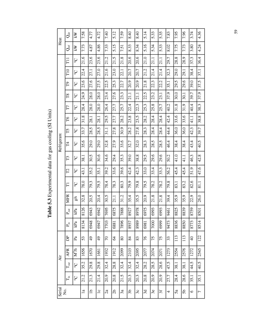
72 5.2 Experimental Test Results Table 5.3 lists all raw experimental data for the gas cooler test conditions. The first column in the table indicates the test serial number. Because refrigerant mass flow rates are not specified in the proposal, some test series were repeated at the same proposed conditions, but at a different refrigerant mass flow rate. This can help us to better understand the effect of refrigerant mass flow rate. Since the inlet conditions (pressure and temperature) of the refrigerant at the gas cooler strongly depend on the discharge conditions of the compressor, pressure and temperature of the refrigerant at the gas cooler inlet are related to each other to some extent. Therefore, the refrigerant inlet pressure and temperature are very difficult to set perfectly simultaneously. This means that each experimental data point might have a very accurate match (normally within.5 "C for temperature, 5% for pressure) on either the proposed pressure or the temperature, but have a less accurate match on the other. Experimental tests showed that the pressure of the refrigerant has a stronger effect on the heat transfer process of the gas cooler than temperature. 58
73

74 W
2. HEAT EXCHANGERS MESA
 1. INTRODUCTION Multiport minichannel and microchannel aluminium tubes are becoming more popular as components in heat exchangers. These heat exchangers are used in various industrial applications and
Role of Nano-technology for improving of thermal performances of vapour compression refrigeration system (VCRS): An Overview
: An Overview") International Journal of Research in Engineering and Innovation Vol-2, Issue-1 (2018), 21-28 International Journal of Research in Engineering and Innovation (IJREI) journal home page: http://www.ijrei.com
International Journal of Research in Engineering and Innovation Vol-2, Issue-1 (2018), 21-28 International Journal of Research in Engineering and Innovation (IJREI) journal home page: http://www.ijrei.com
Main Anthropogenic Sources of Greenhouse Gases Refrigerants
 Main Anthropogenic Sources of Greenhouse Gases Refrigerants Content Refrigerant definition Refrigerants Refrigerants as a source of GHG Refrigerant Definition A refrigerant is a substance or mixture, usually
CHAPTER 1 INTRODUCTION
 1 CHAPTER 1 INTRODUCTION 1.1 Background The science which deals with creating a controlled climate in indoor space is called air conditioning. Earlier days the air-conditioning was treated as a luxury,
CHAPTER 1 INTRODUCTION
 CHAPTER 1 INTRODUCTION 1.1 CFC REFRIGERANTS Since the 1930s, chlorofluorocarbons (CFCs) have been widely used as foam blowing agents, aerosols and especially refrigerants due to their pre-eminent properties
Effects of Non-Uniform Refrigerant and Air Flow Distributions on Finned- Tube Evaporator Performance
 Effects of Non-Uniform Refrigerant and Air Flow Distributions on Finned- Tube Evaporator Performance Jong Min Choi, W. Vance Payne and Piotr A. Domanski National Institute of Standards and Technology Building
EVALUATION OF REFRIGERANT R290 AS A REPLACEMENT TO R22
 EVALUATION OF REFRIGERANT R290 AS A REPLACEMENT TO R22 Ameya P. Shrivastava 1, Choudhari Chandrakishor S. 2 1,2 Mechanical Department, AISSMS College of Engineering, Pune 411001, (India) ABSTRACT HCFC
Low GWP Refrigerants for Air Conditioning Applications
 Purdue University Purdue e-pubs International Refrigeration and Air Conditioning Conference School of Mechanical Engineering 2014 Low GWP Refrigerants for Air Conditioning Applications Samuel F. Yana Motta
Study of R161 Refrigerant for Residential Airconditioning
 Purdue University Purdue e-pubs International Refrigeration and Air Conditioning Conference School of Mechanical Engineering 212 Study of Refrigerant for Residential Airconditioning Applications Yingwen
An Experimental Investigation Of Oil Retention Characteristics In CO2 Air-Conditioning Systems
 Purdue University Purdue e-pubs International Refrigeration and Air Conditioning Conference School of Mechanical Engineering 22 An Experimental Investigation Of Oil Retention Characteristics In CO2 Air-Conditioning
Thermal Design of Condenser Using Ecofriendly Refrigerants R404A-R508B for Cascade Refrigeration System
 Thermal Design of Condenser Using Ecofriendly Refrigerants R404A-R508B for Cascade Refrigeration System A D Parekh, and P R Tailor Abstract Because of damaging effect of CFC refrigerants on stratospheric
NUMERICAL SIMULATION OF VAPOUR COMPRESSION REFRIGERATION SYSTEM USING REFRIGERANT R152A, R404A AND R600A
 NUMERICAL SIMULATION OF VAPOUR COMPRESSION REFRIGERATION SYSTEM USING REFRIGERANT R152A, R404A AND R600A [1] Ranendra Roy, [2] Madhu Sruthi Emani, [3] Bijan Kumar Mandal [1], [2],[3] Department of Mechanical
Chapter 10. Refrigeration and Heat Pump Systems
 Chapter 10 Refrigeration and Heat Pump Systems Learning Outcomes Demonstrate understanding of basic vaporcompression refrigeration and heat pump systems. Develop and analyze thermodynamic models of vapor-compression
TYPICAL INITIAL OUTPUT OF A CO 2 HEAT PUMP
 TYPICAL INITIAL OUTPUT OF A CO 2 HEAT PUMP Paul Maina and Zhongjie Huan mainap@tut.ac.za and huanz@tut.ac.za Department of Mechanical Engineering, Tshwane University of Technology P.O Box Private Bag X680
Due to its low temperature glide about 1.5 approx. (75% less than R-407C and R-427A), it is suitable for a wide range of applications.
, it is suitable for a wide range of applications.") TECHNICAL DATA SHEET R434A () Features and uses of R-434A () is a non-flammable HFC mixture. ODP = 0, compatible with traditional mineral lubricants, alkyl benzene and also with synthetic POE, so there
TECHNICAL DATA SHEET R434A () Features and uses of R-434A () is a non-flammable HFC mixture. ODP = 0, compatible with traditional mineral lubricants, alkyl benzene and also with synthetic POE, so there
Performance Measurement of R32 Vapor Injection Heat Pump System
 Purdue University Purdue e-pubs International Refrigeration and Air Conditioning Conference School of Mechanical Engineering 212 Performance Measurement of Vapor Injection Heat Pump System Yunho Hwang
Experimental Research and CFD Simulation on Microchannel Evaporator Header to Improve Heat Exchanger Efficiency
 Purdue University Purdue e-pubs International Refrigeration and Air Conditioning Conference School of Mechanical Engineering 2006 Experimental Research and CFD Simulation on Microchannel Evaporator Header
NUMERICAL SIMULATION OF VAPOUR COMPRESSION REFRIGERATION SYSTEM USING REFRIGERANT R152A, R404A AND R600A
 ISSN: 2250-0138 (Online) NUMERICAL SIMULATION OF VAPOUR COMPRESSION REFRIGERATION SYSTEM USING REFRIGERANT R152A, R404A AND R600A RANENDRA ROY a1, MADHU SRUTHI EMANI b AND BIJAN KUMAR MANDAL c abc Department
MAL-DISTRIBUTION MODEL OF HEAT EXCHANGERS IN MICRO CHANNEL EVAPORATOR
 MAL-DISTRIBUTION MODEL OF HEAT EXCHANGERS IN MICRO CHANNEL EVAPORATOR Santhosh Kumar Student(M.Tech), Mechanical Dept Gokul group of institutions Visakhapatnam, India M Karteek Naidu ASST PROFF, Mechanical
Investigation of Port Level Refrigerant Flow Mal-distribution in Microchannel Heat Exchanger
 Investigation of Port Level Refrigerant Flow Mal-distribution in Microchannel Heat Exchanger Zhenning Li, Jiazhen Ling, Vikrant Aute, Reinhard Radermacher 12 th IEA Heat Pump Conference, 2017 Center for
Performance of CO2 Cycles with a Two-Stage Compressor
 Purdue University Purdue e-pubs International Refrigeration and Air Conditioning Conference School of Mechanical Engineering 2004 Performance of CO2 Cycles with a Two-Stage Yun Hong Hwang University of
Study of R-161 refrigerant as an Alternate Refrigerant to various other refrigerants
 International Journal of Current Engineering and Technology E-ISSN 2277 4106, P-ISSN 2347 5161 2016 INPRESSCO, All Rights Reserved Available at http://inpressco.com/category/ijcet Research Article Study
The analysis proceeded by adopting the ASHRAE guideline for conventional HVAC chiller applications. This guideline is summarized in Table II.
 Comparison of R134a and R1234ze for New Chiller Systems and for Fluid (Drop-In) in Existing Systems Francis A. Di Bella, P.E. Adam Weaver Colin Osborne Executive Summary A chiller cycle analysis is presented
A Comparison Between Refrigerants Used In Air Conditioning
 A Comparison Between Refrigerants Used In Air Conditioning Derya Özkan, Özden Agra and Özlem Çetin University of Yildiz Technical University, Turkey Corresponding email: tumer@yildiz.edu.tr SUMMARY It
Evaluation of HCFC Alternative Refrigerants
 Evaluation of HCFC Alternative Refrigerants Shaobo Jia Global Innovation Heatcraft Worldwide Refrigeration shaobo.jia@heatcraftrpd.com Introduction It is well-known that HCFC refrigerants widely used in
Performance Enhancement of Refrigeration Cycle by Employing a Heat Exchanger
 Performance Enhancement of Refrigeration Cycle by Employing a Heat Exchanger Abstract Shoeb J. Inamdar 1 H.S. Farkade 2 M. Tech student. (Thermal Engineering) 1, Asst. Professor 2 Department of Mechanical
Ammonia. Background on ammonia as a refrigerant
 Ammonia Danfoss Industrial refrigeration has written a technical paper on things to consider when changing from HFC/HCFC s to ammonia. It outlines some of the main differences between the different plant
Subscripts 1-4 States of the given system Comp Compressor Cond Condenser E Evaporator vol Volumetric G Gas L Liquid
 Simulation Analysis of Compression Refrigeration Cycle with Different Refrigerants P.Thangavel, Dr.P.Somasundaram, T.Sivakumar, C.Selva Kumar, G.Vetriselvan Abstract --- In this analysis, the performance
ASSESSMENT OF R430A REFRIGERANT AS A POSSIBLE SUBSTITUTE TO R134A REFRIGERANT IN LARGE CAPACITY FREEZER
 University of Maiduguri Faculty of Engineering Seminar Series Volume 6, december 5 ASSESSMENT OF REFRIGERANT AS A POSSIBLE SUBSTITUTE TO R34A REFRIGERANT IN LARGE CAPACITY FREEZER S. Shodiya*, M.B. Oumarou
Pressure drop analysis of evaporator using refrigerants R-22, R-404A and R-407C
 drop analysis of evaporator using refrigerants R-22, R-404A and R-407C #1 Pallavi Sawkar, #2 Dr. Pradeep Patil #12 Department of Mechanical Engineering, JSPM s JSCOE, Savitribai Phule Pune University,
Study of Performance of Binary Mixture of R134a and R161 as a Substitution of R134a in a Domestic Refrigerator
 Study of Performance of Binary Mixture of R134a and R161 as a Substitution of R134a in a Domestic Refrigerator Mr. Subodh S. Deshpande Department of Mechanical Engineering M.G.M.s College of Engineering
AN EXPERIMENTAL STUDY OF A REFRIGERATING PLANT WHEN REPLACING R22 WITH HFCs REFRIGERANTS
 AN EXPERIMENTAL STUDY OF A REFRIGERATING PLANT WHEN REPLACING R22 WITH HFCs REFRIGERANTS V. La Rocca 1, A. Messineo 2, D. Panno 1 1 Department of Energy, University of Palermo 2 Engineering Faculty, Kore
EFFECT OF PAG OIL CIRCULATION RATE ON THE HEAT TRANSFER PERFORMANCE OF AIR-COOLED HEAT EXCHANGER IN CARBON DIOXIDE HEAT PUMP SYSTEM
 - 1 - EFFECT OF PAG OIL CIRCULATION RATE ON THE HEAT TRANSFER PERFORMANCE OF AIR-COOLED HEAT EXCHANGER IN CARBON DIOXIDE HEAT PUMP SYSTEM Shun YOSHIOKA, Hyunyoung KIM, Kazushige KASAI, Daikin Industries,
Global Journal of Engineering Science and Research Management
 EXPERIMENTAL AND THEORETICAL STUDY OF MINIATURE VAPOR COMPRESSION CYCLE USING MICROCHANNEL CONDENSER Issam M. Ali Aljubury*, Ahmed Q. Mohammed, Marwa S. Neama * Mechanical Eng. Dept. College of Engineering,
PREDICTION OF THE PRESSURE DROP OF CO 2 IN AN EVAPORATOR USED FOR AIR COOLING ABSTRACT 1. INTRODUCTION 2. EXPERIMENTAL SET-UP AND PROCEDURE
 PREDICTION OF THE PRESSURE DROP OF CO 2 IN AN EVAPORATOR USED FOR AIR COOLING M. POIRIER, D. GIGUÈRE, Z. AIDOUN, M. OUZZANE Natural Resources Canada, CANMET Energy Technology Centre-Varennes 1615, Lionel
Chapter 2. Alternatives to HCFCs and their Characteristics
 Alternatives to HCFCs and their Characteristics Refrigerant - General Chemical used in a cooling system, such as an air conditioner or refrigerator, as the heat carrier which changes from vapour to liquid
Design Optimization of Variable Geometry Microchannel Heat Exchangers
 Purdue University Purdue e-pubs International Refrigeration and Air Conditioning Conference School of Mechanical Engineering 2014 Design Optimization of Variable Geometry Microchannel Heat Exchangers Long
MODELLING AND OPTIMIZATION OF DIRECT EXPANSION AIR CONDITIONING SYSTEM FOR COMMERCIAL BUILDING ENERGY SAVING
 MODELLING AND OPTIMIZATION OF DIRECT EXPANSION AIR CONDITIONING SYSTEM FOR COMMERCIAL BUILDING ENERGY SAVING V. Vakiloroaya*, J.G. Zhu, and Q.P. Ha School of Electrical, Mechanical and Mechatronic Systems,
PERFORMANCE OF DEEP FREEZER BY USING HYDROCARBON BLENDS AS REFRIGERANTS
 Int. J. Chem. Sci.: 14(S2), 2016, 665-674 ISSN 0972-768X www.sadgurupublications.com PERFORMANCE OF DEEP FREEZER BY USING HYDROCARBON BLENDS AS REFRIGERANTS J. THAVAMANI *, MARRIPUDAGALA KOMALI, SHAIK
Experimental Study on Performance Parameters for Refrigerants R22, R410a and R404a at Various Air Outlet Temperatures
 Experimental Study on Performance Parameters for Refrigerants, R41a and R44a at Various Air Outlet Temperatures P. Nagaraju P. G. Student Sanketika Institute of Technology and Management Ch. Kiran Kumar
Comparison of CFC-114 and HFC-236ea Performance in Shipboard Vapor Compression Systems
 United States National Risk Management Environmental Protection Research Laboratory Agency Research Triangle Park, NC 27711 Research and Development EPA/600/SR-97/058 July 1997 Project Summary Comparison
A Theoretical investigation on HC Mixtures as Possible Alternatives to R134a in Vapor Compression Refrigeration
 ANALELE UNIVERSITĂłII EFTIMIE MURGU REŞIłA ANUL XXI, NR. 1, 2014, ISSN 1453-7397 Feiza Memet A Theoretical investigation on HC Mixtures as Possible Alternatives to R134a in Vapor Compression Refrigeration
Design of Divided Condensers for Desiccant Wheel-Assisted Separate Sensible and Latent Cooling AC Systems
 Purdue University Purdue e-pubs International Refrigeration and Air Conditioning Conference School of Mechanical Engineering 2012 Design of Divided Condensers for Desiccant Wheel-Assisted Separate Sensible
HFCs or the Old Refrigerants - what is the best Choice?
 HFCs or the Old Refrigerants - what is the best Choice? Hermann Halozan Institute of Thermal Engineering, Graz University of Technology Inffeldgasse 25 / B, A-8010 Graz, Austria, Phone: +43 316 873-7303
CHAPTER I INTRODUCTION. In the modern life, electronic equipments have made their way
 1 CHAPTER I INTRODUCTION In the modern life, electronic equipments have made their way in to practically every part, which is from electronic gadgets to high power computers. Electronic components have
ijcrr Vol 04 issue 07 Category: Research Received on:06/02/12 Revised on:17/02/12 Accepted on:02/03/12
 EXPERIMENTAL ANALYSIS OF THE EFFECT OF FIN GEOMETRY ON HEAT TRANSFER RATE THROUGH THE REFRIGERATOR CONDENSER ijcrr Vol 04 issue 07 Category: Research Received on:06/02/12 Revised on:17/02/12 Accepted on:02/03/12
Recommendations to retrofit positive existing installations running with HFCs (R404A & R507) RETROFIT POSITIVE & MEDIUM REFRIGERATING SYSTEMS
 RETROFIT POSITIVE & MEDIUM REFRIGERATING SYSTEMS") COMMERCIAL REFRIGERATION RETROFIT POSITIVE & MEDIUM REFRIGERATING SYSTEMS www.tecumseh.com Recommendations to retrofit positive existing installations running with HFCs (R404A & R507) 1-HCFCs & HFCs Retrofit
COMMERCIAL REFRIGERATION RETROFIT POSITIVE & MEDIUM REFRIGERATING SYSTEMS www.tecumseh.com Recommendations to retrofit positive existing installations running with HFCs (R404A & R507) 1-HCFCs & HFCs Retrofit
Paper No. : 04 Paper Title : Unit Operations in Food processing Module 11 : Principles of Refrigeration
 Paper No. : 04 Paper Title : Unit Operations in Food processing Module 11 : Principles of Refrigeration 11.1 Introduction Preservation of foods is a vital processing step in food processing. There are
Experimental Study on Compact Heat Pump System for Clothes Drying Using CO 2 as a Refrigerant. Abstract
 Experimental Study on Compact Heat Pump System for Clothes Drying Using CO 2 as a Refrigerant M. Honma, T. Tamura, Y. Yakumaru and F. Nishiwaki Matsushita Electric Industrial Co., Ltd. Living Environment
HEFAT th International Conference on Heat Transfer, Fluid Mechanics and Thermodynamics Sun City, South Africa Paper number:pp1
 HEFAT27 5 th International Conference on Heat Transfer, Fluid Mechanics and Thermodynamics Sun City, South Africa Paper number:pp PERFORMANCE ANALYSIS OF AIR-COOLED CONDENSER USING MICRO-FIN TUBES P.A.Patil
CHAPTER 2 EXPERIMENTAL APPARATUS AND PROCEDURES
 CHAPTER 2 EXPERIMENTAL APPARATUS AND PROCEDURES The experimental system established in the present study to investigate the transient flow boiling heat transfer and associated bubble characteristics of
(Refer Slide Time: 00:00:40 min)
") Refrigeration and Air Conditioning Prof. M. Ramgopal Department of Mechanical Engineering Indian Institute of Technology, Kharagpur Lecture No. # 10 Vapour Compression Refrigeration Systems (Refer Slide
Refrigeration and Air Conditioning Prof. M. Ramgopal Department of Mechanical Engineering Indian Institute of Technology, Kharagpur Lecture No. # 10 Vapour Compression Refrigeration Systems (Refer Slide
R-407A R-448A R-449A
 GUIDELINES FOR THE UTILIZATION OF R-407A R-448A R-449A 2018 Tecumseh Products Company LLC. All rights reserved. Page 1 of 9 R-407A, R-448A, and R-449A are recognized as suitable alternative refrigerants
An Experimental Study of a Simple Vapour Compression Refrigeration System with Varying Parameters
 An Experimental Study of a Simple Vapour Compression Refrigeration System with Varying Parameters #1 Harshad D Kopurwar, #2 Pravin T Nitnaware, #3 Tapobrata Dey 1 harshvardhan1590@gmail.com #1 Mechanical
Performance Comparison of Ejector Expansion Refrigeration Cycle with Throttled Expansion Cycle Using R-170 as Refrigerant
 International Journal of Scientific and Research Publications, Volume 4, Issue 7, July 2014 1 Performance Comparison of Ejector Expansion Refrigeration Cycle with Throttled Expansion Cycle Using R-170
EXPERIMENTAL INVESTIGATIONS ON AUTOMOBILE AIR CONDITIONERS WORKING WITH R134a AND R290/R600a AS AN ALTERNATIVE
 Karthikeyan, K. et al.: Experimental Investigations on Automobile Air S515 EXPERIMENTAL INVESTIGATIONS ON AUTOMOBILE AIR CONDITIONERS WORKING WITH R134a AND R290/R600a AS AN ALTERNATIVE by Karthikeyan
Enhancement of Round Tube and Flat Tube- Louver Fin Heat Exchanger Performance Using Deluge Water Cooling
 Purdue University Purdue e-pubs International Refrigeration and Air Conditioning Conference School of Mechanical Engineering 2012 Enhancement of Round Tube and Flat Tube- Louver Fin Heat Exchanger Performance
Numerical Study on the Design of Microchannel Evaporators for Ejector Refrigeration Cycles
 Purdue University Purdue e-pubs International Refrigeration and Air Conditioning Conference School of Mechanical Engineering 216 Numerical Study on the Design of Microchannel Evaporators for Ejector Refrigeration
Global Warming Impacts of Ozone-Safe Refrigerants and Refrigeration, Heating, and Air-conditioning Technologies. Steve Fischer Jim Sand Van Baxter
 Global Warming Impacts of Ozone-Safe Refrigerants and Refrigeration, Heating, and Air-conditioning Technologies Steve Fischer Jim Sand Van Baxter Oak Ridge National Laboratory Oak Ridge, Tennessee To be
*Corresponding author;
 PERFORMANCE ANALYSIS OF AUTOMOTIVE AIR CONDITIONING SYSTEM WITH AN INTERNAL HEAT EXCHANGER USING R1234YF UNDER DIFFERENT EVAPORATION AND CONDENSATION TEMPERATURES by Mehmet DIREK a *and Alper KELESOGLU
Life-Cycle Energy Costs and Greenhouse Gas Emissions for Gas Turbine Power
 energy center Paper Report Summary 210-1 174-2 Fixed and Floating Head Pressure Comparison for Madison Ice Arena Life-Cycle Energy Costs and Greenhouse Gas Emissions for Gas Turbine Power July 1998 April,
Heat Transfer Enhancement using Herringbone wavy & Smooth Wavy fin Heat Exchanger for Hydraulic Oil Cooling
 Enhancement using Herringbone wavy & Smooth Wavy fin Exchanger for Hydraulic Oil Cooling 1 Mr. Ketan C. Prasadi, 2 Prof. A.M. Patil 1 M.E. Student, P.V.P.I.T.,Budhagaon,Sangli AP-India 2 Associate Professor,
Thermodynamics II Chapter 5 Refrigeration
 Thermodynamics II Chapter 5 Refrigeration Mohsin Mohd Sies Fakulti Kejuruteraan Mekanikal, Universiti Teknologi Malaysia Objectives Introduce the concepts of refrigerators and heat pumps and the measure
Available online at ScienceDirect. Energy Procedia 109 (2017 ) 56 63
 56 63") Available online at www.sciencedirect.com ScienceDirect Energy Procedia 109 (2017 ) 56 63 International Conference on Recent Advancement in Air Conditioning and Refrigeration, RAAR 2016, 10-12 November
Available online at www.sciencedirect.com ScienceDirect Energy Procedia 109 (2017 ) 56 63 International Conference on Recent Advancement in Air Conditioning and Refrigeration, RAAR 2016, 10-12 November
SIMULATION OF POTENTIAL REFRIGERANTS FOR RETROFIT REPLACEMENT
 SIMULATION OF POTENTIAL REFRIGERANTS FOR RETROFIT REPLACEMENT R. Prapainop 1* and K. O. Suen 2 1 Department of Mechanical Engineering, Kasetsart University, Si Racha Campus, Chonburi, Thailand 2 Department
Performance Study of a Water-to-Water Heat Pump Using Non-azeotropic Refrigerant Mixtures R407C
 H. Abdesselam, et al / International Energy Journal 9 (8) 7-7 7 Performance Study of a Water-to-Water Heat Pump Using Non-azeotropic Refrigerant Mixtures www.serd.ait.ac.th/reric H. Abdesselam *, H.H.
International Journal of Advance Engineering and Research Development
 Scientific Journal of Impact Factor(SJIF): 3.134 e-issn(o): 2348-4470 p-issn(p): 2348-6406 International Journal of Advance Engineering and Research Development Volume 02,Issue 06, JUNE -2015 COMPARATIVE
FABRICATION OF REFRIGERANT FLOW RATE WITH SPIRALLY COILED CAPILLARY TUBE
 FABRICATION OF REFRIGERANT FLOW RATE WITH SPIRALLY COILED CAPILLARY TUBE PRESENTED BY J.SARAVANA PERUMAL 1 Saravananjsp005@gmail.com D.SATHEESH 2 Satheeshd123@gmail.com Contact no: 9789080381 DEPARTMENT
Comparison of Performance of a Residential Air- Conditioning System Using Microchannel and Finand-Tube
 Purdue University Purdue e-pubs International Refrigeration and Air Conditioning Conference School of Mechanical Engineering 2006 Comparison of Performance of a Residential Air- Conditioning System Using
Purdue e-pubs. Purdue University
 Purdue University Purdue e-pubs International Refrigeration and Air Conditioning Conference School of Mechanical Engineering 206 Experimental Investigation of the Refrigerant Flow Distribution Characteristic
Comparative assessment for drop in replacement of R134a in domestic refrigerator.
 Comparative assessment for drop in replacement of R134a in domestic refrigerator. Pravin K. Katare Research Scholar, Department of Mechanical Engineering, G.H.Raisoni College of Engineering Digdoh Hill,
March 2014 AHRI Presents Research Findings at Low-GWP AREP Conference
 March 2014 AHRI Presents Research Findings at Low-GWP AREP Conference In addition to its regular research activities, AHRI is conducting the Low-Global Warming Potential Alternative Refrigerants Evaluation
DEMONSTRATION OF ADVANCED INTEGRATED HVAC&R SYSTEMS IN A LOBLAWS SUPERMARKET IN CANADA
 DEMONSTRATION OF ADVANCED INTEGRATED HVAC&R SYSTEMS IN A LOBLAWS SUPERMARKET IN CANADA Daniel Giguère, Technology Expert Georgi Pajani, Engineer Sophie Hosatte, Section Head, Buildings CETC-Varennes, Natural
Enhancement of COP by Using Spiral and Microchannel Condenser instead of conventional Condenser of VCR System
 Enhancement of COP by Using Spiral and Microchannel instead of conventional of VCR System 1 P.G. Lohote, 2 Dr.K.P. Kolhe. 1 P.G. Student, 2 Professor. 1,2 Department of Mechanical Engineering, JSPM s,
Effects of evaporator load on vapour compression refrigeration system using ecofriendly hydrocarbon refrigerants with sub cooling
 ISSN 2395-1621 Effects of evaporator load on vapour compression refrigeration system using ecofriendly hydrocarbon refrigerants with sub cooling #1 Mr. Sachin Das, #2 Prof. M. V. Khot #1 Student, Mechanical
RS-70 is suitable as a direct replacement for R-22 in low, medium and high temperatures in a great number of applications:
 TECHNICAL DATA SHEET Features and uses of is a non-azeotropic blend of HFC with zero Ozone Depletion Potential et low Global Warming Potential (GWP), formulated to meet the requirements of the F-Gas Regulation
Thermodynamic Analysis of Cascade Refrigeration System Using R12-R13, R290-R23 and R404A-R23
 Thermodynamic Analysis of Cascade Refrigeration System Using R12-R13, R290-R23 and R404A-R23 A. D. Parekh, P. R. Tailor Abstract The Montreal protocol and Kyoto protocol underlined the need of substitution
R-404A Alternative with Low Compressor Discharge Temperature
 2175, Page 1 R-404A Alternative with Low Compressor Discharge Temperature Barbara MINOR 1 *, Vladimir SULC 2, Jeff BERGE 3, Michal KOLDA 4, Michal HEGAR 5 1 DuPont, Fluoroproducts, Wilmington, DE, USA
POTENTIAL OF NON - AZEOTROPIC REFRIGERANT MIXTURE AS WORKING REFRIGERANT IN HOT WATER HEAT PUMPS. FJ Smit and JP Meyer
 POTENTIAL OF NON - AZEOTROPIC REFRIGERANT MIXTURE AS WORKING REFRIGERANT IN HOT WATER HEAT PUMPS FJ Smit and JP Meyer Research Group for Heating and Cooling Technology, Laboratory for Energy, PO Box 524,
Modeling and Testing of an R-23/R-134a Mixed Refrigerant System for Low Temperature Refrigeration
 Marquette University e-publications@marquette Mechanical Engineering Faculty Research and Publications Mechanical Engineering, Department of 1-1-2013 Modeling and Testing of an R-23/R-134a Mixed Refrigerant
Understanding Applications for Alternate Refrigerants. Ron Bonear Emerson Climate Technologies
 Understanding Applications for Alternate Refrigerants Ron Bonear Emerson Climate Technologies Agenda Overview of R-448A/R-449A Refrigerant Development Methodology Evaluation Strategy R-448A /R-449A Refrigerants
Performance Investigation of Refrigerant Vapor- Injection Technique for Residential Heat Pump Systems
 Purdue University Purdue e-pubs International Refrigeration and Air Conditioning Conference School of Mechanical Engineering 2008 Performance Investigation of Refrigerant Vapor- Injection Technique for
COMPARING AIR COOLER RATINGS PART 1: Not All Rating Methods are Created Equal
 By Bruce I. Nelson, P.E., President, Colmac Coil Manufacturing, Inc. COMPARING AIR COOLER RATINGS PART 1: Not All Rating Methods are Created Equal Summary Refrigeration air coolers (evaporators) are widely
Assessment of LPG as a possible alternative to R-12 in domestic refrigerators
 Energy Conversion and Management 44 (2003) 381 388 www.elsevier.com/locate/enconman Assessment of LPG as a possible alternative to R-12 in domestic refrigerators Bilal A. Akash a, *, Salem A. Said b a
A Review of Hydroflorocarbons (HFC S) Refrigerants as an Alternative to R134a Refrigerant
 Refrigerants as an Alternative to R134a Refrigerant") International Journal of Current Engineering and Technology E-ISSN 2277 416, P-ISSN 2347 5161 216 INPRESSCO, All Rights Reserved Available at http://inpressco.com/category/ijcet Research Article A Review
International Journal of Current Engineering and Technology E-ISSN 2277 416, P-ISSN 2347 5161 216 INPRESSCO, All Rights Reserved Available at http://inpressco.com/category/ijcet Research Article A Review
Performance Analysis of Electronic Expansion Valve in 1 TR Window Air Conditioner using Various Refrigerants
 Performance Analysis of Electronic Expansion Valve in 1 TR Window Air Conditioner using Various Refrigerants CHENNUCHETTY CHINNARAJ * Associate Professor in Mechanical Engineering, Government College of
Experimental investigation of Hybrid Nanofluid on wickless heat pipe heat exchanger thermal performance
 Experimental investigation of Hybrid Nanofluid on wickless heat pipe heat exchanger thermal performance #1 Jaydev S. Bade, #2 Dr. Nitin U. Korde 1 Department of Mechanical Engineering, Savitribai Phule
Technology Application of Environmental Friendly Refrigeration (Green Refrigeration) on Cold Storage for Fishery Industry
 on Cold Storage for Fishery Industry") Journal of Physics: Conference Series PAPER OPEN ACCESS Technology Application of Environmental Friendly Refrigeration (Green Refrigeration) on Cold Storage for Fishery Industry To cite this article: IM
Journal of Physics: Conference Series PAPER OPEN ACCESS Technology Application of Environmental Friendly Refrigeration (Green Refrigeration) on Cold Storage for Fishery Industry To cite this article: IM
Performance Comparisons Of A Unitary Split System Using Microchannel and Fin-Tube Outdoor Coils, Part I: Cooling Tests
 Purdue University Purdue e-pubs International Refrigeration and Air Conditioning Conference School of Mechanical Engineering 2002 Performance Comparisons Of A Unitary Split System Using Microchannel and
Comparison of Oil Retention in R134a and CO 2 Climate Control Systems
 Comparison of Oil Retention in R134a and CO 2 Climate Control Systems Lorenzo Cremaschi Yunho Hwang,Ph.D. Reinhard Radermacher, Ph.D. CEEE University of Maryland Objective: Introduction Research Overview
ANALYSIS OF LGWP ALTERNATIVES FOR SMALL REFRIGERATION (PLUGIN) APPLICATIONS
 APPLICATIONS") ANALYSIS OF LGWP ALTERNATIVES FOR SMALL REFRIGERATION (PLUGIN) APPLICATIONS YANA MOTTA, S. (*), SPATZ, M., VERA BECERRA, E. (*) Honeywell International, 2 Peabody Street, Buffalo, NY 1421, Samuel.YanaMotta@honeywell.com
ANALYSIS OF LGWP ALTERNATIVES FOR SMALL REFRIGERATION (PLUGIN) APPLICATIONS YANA MOTTA, S. (*), SPATZ, M., VERA BECERRA, E. (*) Honeywell International, 2 Peabody Street, Buffalo, NY 1421, Samuel.YanaMotta@honeywell.com
Analysis of Constant Pressure and Constant Area Mixing Ejector Expansion Refrigeration System using R-1270 as Refrigerant
 Analysis of Constant Pressure and Constant Area Mixing Ejector Expansion Refrigeration System using R-1270 as Refrigerant Ravi Verma 1, Sharad Chaudhary 2 1, 2 Department of Mechanical Engineering, IET
Alternatives in the AC & Chiller Sectors. Sukumar Devotta and Lambert Kuijpers OORG Refrigeration
 Alternatives in the AC & Chiller Sectors Sukumar Devotta and Lambert Kuijpers OORG Refrigeration 1 Outline ASHRAE position paper summary which marks a difference in the US approach dealing with various
COMPACT HEAT EXCHANGERS FOR MOBILE CO 2 SYSTEMS
 COMPACT HEAT EXCHANGERS FOR MOBILE CO 2 SYSTEMS A. Hafner SINTEF Energy Research Refrigeration and Air Conditioning Trondheim (Norway) ABSTRACT The natural refrigerant carbon dioxide (CO 2 ) with all its
Refrigeration Cycle And Compressor Performance For Various Low GWP Refrigerants
 Purdue University Purdue e-pubs International Compressor Engineering Conference School of Mechanical Engineering 26 Refrigeration Cycle And Compressor Performance For Various Low GWP Refrigerants Jit Guan
Performance Comparison of Hydronic Secondary Loop Heat Pump and Conventional Air-Source Heat Pump ABSTRACT 1. INTRODUCTION
 2597, Page 1 Performance Comparison of Hydronic Secondary Loop Heat Pump and Conventional Air-Source Heat Pump Ian H. BELL 1 *, James E. BRAUN 2 1 Bell Thermal Consultants ian.h.bell@gmail.com 2 Purdue
Visualization of Evaporatively Cooled Heat Exchanger Wetted Fin Area
 Purdue University Purdue e-pubs International Refrigeration and Air Conditioning Conference School of Mechanical Engineering 2014 Visualization of Evaporatively Cooled Heat Exchanger Wetted Fin Area Sahil
Scientific Principals and Analytical Model. Charcoal Cooler. Lisa Crofoot MECH 425, Queens University
 Scientific Principals and Analytical Model Charcoal Cooler Lisa Crofoot MECH 425, Queens University 1.0 Scientific Principles Evaporative cooling is based on the principle that water requires heat energy
Experimental study on heat transfer characteristics of horizontal concentric tube using twisted wire brush inserts
 International Journal of Current Engineering and Technology E-ISSN 2277 416, P-ISSN 2347 5161 216 INPRESSCO, All Rights Reserved Available at http://inpressco.com/category/ijcet Research Article Experimental
TWO-PHASE MICRO-CHANNEL HEAT SINK FOR SPACE CRAFT THERMAL CONTROL
 TWO-PHASE MICRO-CHANNEL HEAT SINK FOR SPACE CRAFT THERMAL CONTROL Vance K. Hashimoto Department of Mechanical Engineering University of Hawai i at Mānoa Honolulu, HI 96822 ABSTRACT The increasing requirements