TUCSON Plumbing & Heating Products
|
|
|
- Amberly Harrison
- 6 years ago
- Views:
Transcription


1 Superior Plumbing Products Tucson Head Office: Santry Avenue, Dublin 9 D09K160, Ireland sales@tucsonproducts.co.uk Tel:


2 CONTENTS TUCSON A-Rated Circulating Pumps General Information... 5 & 6 Metre A-Rated Circulating Pump... 8 Metre A-Rated Circulating Pump TUCSON Booster Pumps General Information... SBP-90 Booster Pump... SBP-100 Booster Pump TUCSON Expansion Vessels General Information... Heating Expansion Vessels... Potable Expansion Vessels TUCSON Motorised Valves General Information... Motorised Valves With Detachable Heads TUCSON Automatic Air Bottle General Information INSTANTOR Press System All other products available.... T: E: sales@tucsonproducts.co.uk W: 37


3 TUCSON A-RATED CIRCULATING PUMP S Fluid Dynamics 2 2
4 TUCSON A-RATED CIRCULATING PUMP S GENERAL INFORMATION 1. A-Rated Circulating Pump Our A-Rated circulating pumps are designed for the circulation of water in heating systems. They can be used in the following installations: Underfloor heating systems One-pipe systems Two-pipe systems They incorporate a permanent-magnet motor and variable-pressure control, enabling continuous adjustment of the pumps performance to the actual requirements. NB: When the pump is being used for a solid fuel application, please ensure it is switched to a manual setting ONLY 2. Advantages of installing an A-Rated Circulating Pump Our A-Rated Pumps are easy to install in most cases, with the factory setting allowing the pump to be started without making any adjustments. A high degree of comfort due to minimal noise from the pump and throughout the system. Low energy consumption compared to conventional circulating pumps. Our A-Rated pumps are fully compliant with the European Union ErP (Energy-related Products) directive, they exceed the bench mark for energy efficiency with an EEI rating of Pump liquid The water within the system and the pump must be clean, non-aggressive and non-explosive. It must also be free from solid particles, fibres or mineral oil. In heating systems, the water must meet the requirements of accepted standards for water quality in a heating system. 4. ErP (ecological design) directive The benchmark for the most efficient circulators is EEI Information on recycling/disposal: The product should be disposed of seprately from household waste in line with local laws and regulations. When the product reaches its end of life, dispose of it at your local waste collection point/recycling centre. The separate collection and recycling of your product at the time of disposal will help conserve natural resources and ensure that it is recycled in a manner that protects human health and the environment. 5. Warranty Tucson A-Rated circulating pumps are sold with a 2 year warranty effective from date of purchase. This warranty covers any manufacturing fault which may cause the pump to fail and not perform its designed operations correctly. The warranty is valid on the assumption the following has been applied to the installation: Product installed correctly and used as specified in the instructions. It has been installed by a fully qualified tradesperson. The installation complies with the local building regulations and also any regulations which are relative to circulating pump installations. The warranty of the pump is invalid if any of the following occurs during installation: The pump has been installed to operate for other purposes than what it is designed for. The pump is not installed by a qualified or competent person. The pump has been installed incorrectly or not to the installation instructions. The pump has failed outside of the warranty period. The pump has been damaged by outside interference such as bad workmanship or physical damage. 3
 15(=1 ), 25(= 1½ ), 32(=2 ) Maximum head (M) Electrical auto Port to port length (mm) Type Key 6M Screwed")
5 5 & 6 METRE HEAD A-RATED CIRCULATING PUMP Code Efficiency Voltage Frequency Speed Isolation Class Fluid Temperature Working Range Max Working Pressure Ambient Temperature Waterproof Rating Pump Weight Min Power Output Max Power Output Type Key 5M Screwed pipe pump Nominal width (mm) 15(=1 ), 25(= 1½ ), 32(=2 ) Maximum head (M) Electrical auto Port to port length (mm) Type Key 6M Screwed pipe pump Nominal width (mm) 15(=1 ), 25(= 1½ ), 32(=2 ) Maximum head (M) Electrical auto Port to port length (mm) (5M) / (6M) EEI 0.20 Single Phase, 230V +/- 10% 50 Hz 1 to 3 Speed, Auto F -10 C to 110 C 10 Bar -10 C to 50 C IP44 2.2KG 5W 45W (5M) / 47W (6M) RS 25/6 EA 130 RS 25/7 EA 130 4

6 5 METRE & 6 METRE HEAD HEAD A-RATED A-RATED CIRCULATING PUMP PUMP Pump Components Pump Dimensions Ref Description Connection Box Label Cover Screw Gasket Bleed Screw Motor Housing Gasket Stator With Wire Shield Cover 1 Bearing Rotor Shaft O-Ring Thrust Ring Gasket Shield Cover 2 Impeller Pump Body Parts Pump Body Material ABS+PC ABS+PC SUS304 NBR COPPER ZL104 NBR COPPER H62 SUS304 A12O397% MAGANET A12O397% NBR NBR NBR SUS304 PES SUS304 IRON HT G1-1/2 Control Panel Elements Ref Description Screen to show actual working power Light fields indicating AUTO mode Min speed for manual button Mid speed for manual button Max speed for manual button Light fields indicating night mode Push-button to select night mode Push-button for selection of pump settings CP1 indicating min constant pressure curve CP2 indicating max constant pressure curve PP1 indicating min proportion pressure curve PP2 indicating max proportion pressure curve This A-Rated Circulating Pump has nine optional settings which can be selected with the push-button. (Ref. 8 in above table) The pump setting is indicated when the light below the icon is illuminated. Every time the push button is pressed, the pump setting is changed. 5

7 5 & 6 METRE HEAD A-RATED CIRCULATING PUMP Relation between pump setting and pump performance Definition of PP1, PP2, CP1, CP2 PP1/PP2 If flow resistance in the distribution system is not negligible, proportional pressure control is recommended. The differential pressure across the circulator increases when flow increases. The proportional pressure control compensates for the flow resistance in the distribution and supply system with the result that the differential pressure across the control valves is nearly constant and a good control performance is obtained both at full loads as well as at partial loads operation. Different slopes of the proportional control curves can be selected to fit the pump to the resistance in the actual heating system, in which it is installed. CP1/CP2 Constant pressure controls is recommended if flow resistance in the distribution and supply system (pipe, boiler, heat exchanger etc.) is low. The differential pressure across the circulator is constant and independent of the flow. Due to the low flow resistance in the distribution system the differential pressure across the control valves is nearly constant and optimal control performance is obtained both at full loads as well as at partial loads operation. Setting Pump Curve Function PP1 PP2 CP1 CP2 III II I Lowest proportional Pressure curve Highest proportional Pressure curve Lowest constant Pressure curve Highest constant Pressure curve Speed III Speed II Speed I AUTO Ex-Factory Setting Night Mode The duty point of the pump will move up or down on the lowest proportional-pressure curve, depending on heating demand. The head (pressure) is reduced at falling heating demand and increased at rising heating demand. The duty point of the pump will move up or down on the highest proportional-pressure curve, depending on the heating demand. The head (pressure) is reduced at falling heating demand and increased at rising heating demand. The duty of the pump will move out or in on the constantpressure curve, depending on the heating demand. The head (pressure) is kept constant, irrespective of the heating demand. The duty of the pump will move out or in on the constantpressure curve, depending on the heating demand. The head (pressure) is kept constant, irrespective of the heating demand. Pump runs at a constant speed and consequently on a constant curve. In speed III, the pump is set to run on the maximum curve under all operating conditions. Quick venting of the pump can be obtained by setting the pump to speed III for a short period. Pump runs at a constant speed and consequently on a constant curve. In speed II, the pump is set to run on the medium curve under all operating conditions. Pump runs at a constant speed and consequently on a constant curve. In speed I, the pump is set to run on the minimum curve under all operating conditions. Under AUTO mode, the power of the pump automatically alters up or down. Select night mode, after a period of time the power automatically alters. After two hours, it will be down lowest between 5-10 watt. After seven hours, the pump moves from night mode to its original setting. 6

8 8 METRE HEAD A-RATED CIRCULATING PUMP Code Efficiency Voltage Frequency Speed Isolation Class Fluid Temperature Working Range Max Working Pressure Ambient Temperature Waterproof Rating Pump Weight Min Power Output Max Power Output EEI 0.23 Single Phase, 230V +/- 10% 50 Hz 1 to 6 Speed, Auto F -10 C to 110 C 10 Bar -10 C to 50 C IP44 3.3KG 10W 130W Type Key Screwed pipe pump Nominal width (mm) 15(=1 ), 25(= 1½ ), 32(=2 ) Maximum head (M) Electrical auto Port to port length (mm) RS 25/8 EA 180 7

9 8 METRE HEAD A-RATED CIRCULATING PUMP Pump Components Ref Description Terminal Box Pump Housing Screw Copper Screw Gasket Wiring Shielding Parts Rotor Thrust Parts Gasket Shielding Cover Impeller Pump Body Parts Pump Body Material ABS+PC ZL104 SUS304 HPB59-1 NBRNBR COPPER SUS304 SILICON NBR+A % NBR SUS304 PES SUS304 HT304 Pump Dimensions G1-1/2 Control Panel Elements Ref Description Light in constant pressure Light in proportional pressure ECO mode Pump Vent - When selected, the pump will run at full power to release trapped air. Power Light Control Mode - Button is used to change the pumps mode, for example, from constant pressure to proportional pressure, or to ECO mode, also for air-venting mode. Speed Indicator - The 6 lights show the different working conditions. Only under two modes (constant pressure and proportional pressure) these lights can be chosen. Set - This button is used for setting the different speeds (light in 1, 2, 3, 4, 5, 6) for two modes. Using this button, speeds from max. to min. can be chosen. This A-Rated Circulating Pump has fourteen optional settings which can be selcted with the push-button. (Ref. 8 in above table) The pump setting is indicated when the light below the icon is illuminated. Every time the push button is pressed, the pump setting is changed. 8
10 8 METRE HEAD A-RATED CIRCULATING PUMP Relation between pump setting and pump performance H(m) 9 CP2 CP3 CP4 CP5 PP2 PP3 PP4 PP5 ECO Q(m³/h) Control Panel Pump Curve Description CP2, CP3, CP4, CP5 The operating point moves back and forth on the curve according to the volume of flow from the system. As shown in graph, the pressure remains constant and is not affected by the volume demands of flow. CP1 -- Min Speed CP6 -- Max Speed PP2, PP3, PP4, PP5 The two speeds are the min. and max. under constant pressure, the curve shown as in graph can not keep constant. It rises and goes down as manual operation. The operating point moves back and forth on the proportional pressure curve according to the volume of flow from system. As shown in the graph, the pump is directly proportional to the flow demands. PP1 -- Min Speed PP6 -- Max Speed ECO The two speeds are the min. and max. under proportional pressure, the curve shown as in graph can not keep constant. It rises and goes down as manual operation. 1. In this mode, the pump operates in autoadaption, and adjusts to system requirements. 2. Under ECO mode, the pump is controlled by means of proportional pressure. 9
11 TUCSON A-RATED CIRCULATING PUMP Installation Instructions 5M & 6M A = 130mm B = 130mm 8M A = 180mm B = 230mm 5M & 6M C = 120mm 8M C = 130mm 10
12 TUCSON A-RATED CIRCULATING PUMP Electrical Connection The electrical connection for the TUCSON circulating pump must be installed correctly by a fully qualified tradesperson. An electrical connection for the TUCSON circulating pump is supplied with every pump and must be used. The frequency and supply voltage must be the same as per instructions and control panel. All electrical connections must comply with local building regulations. Once power has been connected correctly to the pump and switched on, the control panel will illuminate to show the power supply is working correctly. Commissioning Before initial pump start up please ensure the following The pump has been installed correctly and there are no leaks on the plumbing connections. The electrical connections have been installed correctly and the correct power is running to the pump when it is switched on and in operation. The liquid in the heating system is clean. Both service valves on each side of the pump are open to ensure the water will flow through the pump when running. Ensure the system is full with water and all air has been removed. N.B Do not run the pump without any water in the system as this may lead to failure and will not be covered under warranty. N.B Do not use the pump as a way to vent the system of air. We recommend that an automatic air bottle is installed at the highest point possible on the heating circuit to ensure the air can be removed from the system. 11
13 TUCSON A-RATED CIRCULATING PUMP Fault finding chart WARNING Before starting any work on the pump, make sure the electricity supply has been switched off and that it cannot be accidentally switched on. FAULT CONTROL PANEL CAUSE REMEDY 1. The pump does not No display light a) One fuse in the Replace the fuse run installation is blown b) The currentoperated or voltageoperated Check circuit breaker & have replaced if necessary circuit breaker has tripped over c) The pump is Replace the pump Power light on 2. Noise in the system Ensure power and light field for pump setting are on defective a) Electricity supply failure b) The pump is blocked Check that the electricity supply falls within the specified range Remove the impurities a) Air in the system Vent the system b) The flow is too high Reduce the suction head 3. Noise in the pump Ensure power and light field for pump setting are on 4. Insufficient circulation Ensure power and light field for pump setting are on a) Air in the pump 8M - Switch to pump vent setting & run for a short period of time 5/6M Open bleed screw to release any trapped air. b) The inlet pressure is too low a) The pump performance is too low Increase the inlet pressure. Check the air volume in the expansion tank, if installed Increase the suction head 12

14 TUCSON SBP BOOSTER PUMPS TUCSON SBP-90 Fluid Dynamics TUCSON SBP
15 TUCSON SBP BOOSTER PUMPS GENERAL INFORMATION 1. SBP Booster Pumps The SBP Booster Pumps are designed for the boosting of water in the following applications Domestic, Light Commercial and Irrigation use Our range of booster pumps are designed to increase the pressure where needed in both cold and hot water(sbp90). SBP90 - is a low noise, horizontal multi-stage centrifugal booster pump complete with automatic pressure control unit The pump itself has three stainless steel impellers inside and a ½ HP motor which enables the pump to have a max head of 37M and a static pressure of 3bar. The pump also has the following features when used with the automatic pressure control unit Dry run protection Integrated non return valve in the pressure controller Low decibel rating of <45db(A) at 5 metres SBP100 - is an all in one automatic booster pump which combines motor, pump, accumulator, pressure switch and flow switch all in one unit. The pump has two impellers inside and a 1HP motor which enables the pump to have a max head of 32M and a static head pressure of 3bar. The pump also has the following features Dry run protection Motor thermal protection Suction lift of 5M Built in pressure tank this reduces the number of starts and stops in case there is a small water discharge from a dripping tap or leak in the system, this in turn will cause less wear on your TUCSON pump 2. Pump Liquid These pumps are designed to pump the following types of liquids Rainwater, potable water and other clean, thin, nonaggressive liquids, not containing solid particles or fibres. 3. Warranty Tucson A-Rated circulating pumps are sold with a 2 year warranty effective from date of purchase. This warranty covers any manufacturing fault which may cause the pump to fail and not perform its designed operations correctly. The warranty is valid on the assumption the following has been applied to the installation: Product installed correctly and used as specified in the instructions. It has been installed by a fully qualified tradesperson. The installation complies with the local building regulations and also any regulations which are relative to booster pump installations. The warranty of the pump is invalid if any of the following occurs during installation: The pump has been installed to operate for other purposes than what it is designed for. The pump is not installed by a fully qualified tradesperson. The pump has been installed incorrectly or not to the installation instructions. The pump has failed outside of the warranty period. The pump has been damaged by outside interference such as bad workmanship or physical damage. 14


16 TUCSON SBP-90 BOOSTER PUMP Complete with automatic pressure control unit Code Power Voltage Frequency Head Rated / Head Max Isolation Class Fluid Temperature Working Range Max Working Pressure Max Environmental Temperature Waterproof Rating Pump Weight Impeller Motor Dry Run Protection Non-Return Valve ½ HP / 370W Single Phase, 230V +/- 10% 50 Hz 33M / 37M F -20 C to 104 C 8 Bar 50 C IP55 9.2KG Stainless Steel Air Cooled Yes Integrated in controller Pump Dimensions B1 B2 B3 H1 H2 L1 L2 L3 L4 L5 L
17 TUCSON SBP-90 BOOSTER PUMP Pump Components Ref Description Material Qty Ref Description Material Qty 1 Dust cap G Bottom part of terminal box 1 2 Plug G3/ Cross recessed pan head screw and washer assemblies M4x8 4 3 O - ring D15x Connection pole 1 4 Inside hexagonal bolt M8 x Serrated lock washer external teeth Clamp plate 1 32 Washer Pump casing 1 33 Hexagonal nut M4x8 5 7 O - ring D116x Cross recessed pan head tapping screws St3 5x Type 1 hexagonal nut M Capacitor 15uf/450V 2 9 Spring washer O - ring d120x Impeller press tube 1 37 Wiring Diagram 1 11 Inlet section 1 38 Upper part of terminal box 1 12 Impeller 3 39 Cross recessed pan head tapping screws ST3. 5x Diffuser 1 40 Cross recessed pan head spring washer and plain washer assemblies M5 x Long sleeve L= Cable gland 1 15 Outlet section 1 42 Cable 1 16 Short sleeve L= Terminal box nut 1 17 Shaft shield ring 1 44 Nut plug for terminal box 1 18 Mechanical seal LX The three wave D Pump cover 1 46 Back cover 1 20 O - ring D108x Hexagon bolt M5x Retaining ring 1 48 Fan 1 22 Front cover 1 49 Axial spring collare 1 23 Bearing Fan cover 1 24 Rotor assembling 1 51 Cross receased pan head screw and washer assemblies M4x Bearing Ac Drain plug 1 26 Frame assembly 1 53 Base 1 27 Terminal box pad 1 54 Inside hexagonal bolt M6 x

18 TUCSON SBP-90 BOOSTER PUMP Performance Curve Fault finding chart WARNING Before starting any work on the pump, make sure the electricity supply has been switched off and that it cannot be accidentally switched on. Problem Possible Reason Solution The pump does not run The pump does not run properly The pump runs but no water The flow is reduced The motor is over heating The pump stops soon after starting a) The voltage is not correct b) Fuse or thermal protector prevents the pump from running a) Head is too high b) Water level is too low c) No Water d) Leakage on inlet pipe a) The foot valve is blocked b) The impellar is corroded c) The bottom valve is not in water d) No priming water e) The impeller is seriously damaged a) The foot valve is blocked b) The head is too high c) The water level is too low d) The impeller is seriously damaged a) Low voltage b) Insufficient ventilation in pump room a) Low voltage b) Insufficient ventilation in pump room a) Check voltage on the name plate b) Check the fuse or terminal protector a) Check head is suitable b) Check the suction head c) Place the valve in water d) Check suction conditions a) Clean or replace the foot valve b) Replace the impeller c) Fill the suction section with water d) Fill the pump with water e) Check the suction conditions a) Clean or replace the foot valve b) Check the installation height c) Check the suction and re-install the pump. d) Replace the impeller a) Contact the electric power company to supply stable voltage b) Improve ventilation a) Contact your electric power company to supply stable voltage b) Improve ventilation 17
19 TUCSON SBP-90 BOOSTER PUMP Electrical Connection The electrical connection for the TUCSON booster pump must be installed correctly by a fully qualified tradesperson. Ensure the voltage(v), frequency (Hz), phase (PH) conforms to those marked on the data plate label. If there is a surge or drop in voltage by ±10%, the motor will stop running to prevent damage to the pump. All electrical connections must comply with local building regulations. Once power has been connected correctly to the pump and switched on, the automatic pressure control unit will illuminate to show the power supply is working correctly. Commissioning Before initial pump start up please ensure the following The pump has been installed correctly and there are no leaks on the plumbing connections. The electrical connections have been installed correctly and the correct power is running to the pump when it is switched on and in operation. The liquid in the system is clean. Ensure both the system and pump is full with water and all air has been removed. For stable operation, please mount and bolt the booster pump securely. The place of installation must be dry with good ventilation and adequate space for future maintenance and service. A proper shelter is required for outdoor installation; exposure to rain will damage the insulation of electrical wiring. Be careful not to allow any foreign objects (PVC adhesive gum, dirt, sand etc.) into the pump, otherwise the pump will be damaged and its operating life shortened. It is recommended to use a strainer to prevent that. 18

20 TUCSON AUTOMATIC PRESSURE CONTROL UNIT Intensity Max Voltage Frequency Max Working Pressure Max Working Temperature Protection Rating Connection Restart Pressure 10A 220V - 240V 50 Hz 10 Bar 60 C IP65 1 Male 1.5 Bar Do not remove the electronic board from the control box. The wiring diagram inside the terminal block shows how to make a correct connection. A wrong connection will destroy the electronic circuit. Cable used for connection must be 3 core with compulsory grounding end. It should have an outer diameter of 7.5mm min and 8.5mm max. One of the leading ends of the cable must be lower than the position of the fixing screws while the cable being connected to the power as shown in the drawing below here. The four screws must be fastened Inlet These two nuts for fixing cables must be fastened This part must be lower than the fixing nuts 3 core cable with OD 7.5mm - 8.5mm Power Pump Starting Up When the unit is connected to the power supply, the green LED Power On lights up and the yellow LED On (pump in operation) indicates that the pump has been started. The pump will continue to run while the system fills the pipes and the required pressure is achieved. If the red LED Failure lights up, keep the Restart button pressed and wait, with a tap opened, until the red LED turns off. When the Restart button is released, and the tap closed off, the unit stops the pump at its maximum pressure. Functioning After a successful start-up has been achieved, the unit is programmed to perform all the pump control operations automatically. If an operational breakdown should occur, such as water failure, obstruction of the suction pipe etc., the unit will recognise a breakdown and the red LED Failure will light up. Simultaneously, the pump will stop operating to prevent further damage. Rectifiy the failures that have caused the blockage and restart the system by pressing the Restart button. 19

21 TUCSON AUTOMATIC PRESSURE CONTROL UNIT Installation Instructions If the column of water between the pump and the highest tap exceeds 15M, the unit cannot be installed directly on the pump, but it has to be raised until the column of water between the unit and the highest tap does not exceed 15 M. I.E. If column of water is 20M from the pump, the unit must be placed 5M higher than the pump. The unit is equipped with a check valve to prevent the pipeline from losing pressure. No taps can be installed between the pump and the control unit. It is advisable to connect the unit outlet to the system by means of a flexible hose. CONTROL UNIT Safety valve preventing water emission in case diaphragm breaks. The unit must be installed with the arrows in the upward position. Pump s Pressure: The unit is pre-set by the manufacturer at a restarting pressure of 1.5 bar. The pressure produced by the pump must be normally 0.8 bar higher than the pre-set pressure. Before starting the unit check suction and ensure that the pump is primed. The unit can be installed directly on the pump, or between the pump and the first tap. PUMP L Hz V Wiring Diagram L1 N N PE Connect the unit to the pump motor U V M 1- Connection of single phase 220V pump up to 1.1 Kw. WARNING Before starting any work on the pump, make sure the electricity Fault finding chart supply has been switched off and that it cannot be accidentally switched on. TYPE OF DEFECT CAUSES DEPENDING ON THE UNIT CAUSES NOT DEPENDING ON THE UNIT The pump does not start The pump does not stop The electronic card is broken The electric card is broken The flow detector is blocked in the upper position The reset button is blocked The pump does not provide sufficient pressure Voltage failure Pump jammed Electric cables inverted(line/motor) Presence of leaks which are higher than the minimum flow 0.6 l/min Intermittent pump not working The pump is jammed The electronic card is broken The pump does not provide sufficient pressure The electronic card is broken The pump provides a pressure which is lower than the restarting pressure Presence of leaks which are higher than the minimum flow 0.6 l/min Water failure 20
22 TUCSON SBP-100 BOOSTER PUMP Code Power Voltage Frequency Head Rated / Head Max Isolation Class Fluid Temperature Working Range Max Working Pressure Max Environmental Temperature Waterproof Rating Pump Weight Impeller Motor Dry Run Protection Non-Return Valve HP / 750W Single Phase, 220V - 240V 50 Hz 25M / 32M E 5 C to 40 C 6 Bar 40 C IP KG Noryl Air Cooled Yes Integrated Pump Dimensions A B C D E
23 TUCSON SBP-100 BOOSTER PUMP Drawing For Parts List Pump Components ASB25 / 50 / Hz ft If e g ly. er e e. Description Installation and Piping The ASB series booster pump is an all-in-one compact and reliable automatic 1. For stable operation, please mount and bolt the booster pump securely. The multistage centrifugal booster pump, which 32 integrates 33 motor, pump, accumulator, place of installation must be dry with good ventilation and adequate space pressure switch and flow Description switch, all in one unit. The flow switch equipped with for future maintenance Installation and and service. Piping A proper shelter is required for outdoor the pump prevents the pump from continuously starting and stopping under installation; exposure to rain will damage the insulation of electrical wiring. The ASB series booster pump is an all-in-one compact and reliable automatic 1. For stable operation, please mount and bolt the booster pump secure small discharge. It is very multistage suitable centrifugal for domestic booster water pump, supply. which integrates motor, pump, accumulator, 2. The pump should place be installed of installation as close must as be possible dry with to good the ventilation reservoir or and well. adequate For Operating Conditions pressure switch and flow switch, all in one unit. The flow switch equipped with hot water (40~90ºC) for future pumping, maintenance negative and inlet service. pressure A proper application shelter is is required for o 1. Ambient Temperature : +5 the ºC pump ~ +40 prevents ºC 3. the Maximum pump Operating from continuously Pressure starting and stopping under installation; exposure to rain will damage the insulation of electrical w : 6 kg/cm 2 to avoid cavitations. Piping joints should be fitted carefully to prevent leaks. small discharge. It is very suitable for domestic water supply. 2. Liquid Temperature 4. Rated Discharge Head / Height A leak in the suction 2. The pump piping should will cause be installed the pump as close to lose as possible suction to capacity, the reservoir while or w Regular Model : +5ºC ~ +40ºC Operating Conditions ASB25(H) : 1.5 kg/cm 2 / 15 m a leak in the discharge hot water piping (40~90ºC) will pumping, cause a negative high frequency inlet pressure ON/OFF application motor is re Hot Water Model : +5ºC ~ ºC Ambient Temperature ASB50(H) : +5 ºC ~ +40 : 2.0 ºC kg/cm 3. 2 Maximum / 20 m Operating Pressure : 6 kg/cmoperation 2 while to the avoid faucets cavitations. valves Piping are closed. joints should be fitted carefully to preven 2. Liquid Temperature ASB100(H) : 2.5 kg/cm 4. 2 Rated / 25 mdischarge Head / Height A leak in the suction piping will cause the pump to lose suction capacity Construction ( ASB-H Hot water Model with stainless steel impeller.) Construction Item ( ASB Name Regular model Model : Description with +5ºC ~ thermoplastic +40ºC Itemimpeller.) ASB25(H) Name : 1.5 kg/cm 2 / 15 m Description Item a leak in the Name discharge piping will Description cause a high frequency ON/OFF Hot Water Model : +5ºC ~ +90ºC ASB50(H) : 2.0 kg/cm 2 / 20 m Item Name Description operation Item while the Name faucets valves Description are Item closed. Name Description Item Name Description Item Name Description Item Name Description 1 Motor 1Φ 2 Poles 15 ASB100(H) Inlet Flange : 2.5 kg/cm Gasket 2 / 25 m Rubber 1 Motor Poles 13 Bolt Pressure Tank SUS304 S45C 24 Wiring Box NYLON 1 Motor 1 2 Poles 15 Inlet Flange Gasket Rubber 25 Bolt S45C Construction ( ASB-H Hot water Model with stainless steel impeller.) 2 Bolt S45C 14 Pump Cover Bolt SUS Bolt S45C 2 Bolt S45C Construction 16 Inlet Flange ( ASB Regular NYLON model 26 Wiringwith Box Cover thermoplastic NYLON impeller.) 2 Bolt S45C 16 Inlet Flange NYLON 3 Pump Casing Item 26 NorylWiring Name 15 Inlet Box Description Flange Cover Gasket Item Rubber Name NYLON 26 Description Wiring Box Cover Item NYLON Name De 3 Pump Casing Noryl Item17 Name Flange Bolt Description SUS304 Item 27 Name Bolt Description S45C Item Name Description Ceramic+ 1 Viton Motor 16 1 Inlet 2 Poles Flange 13 Pressure NYLON Tank 27 SUS304Bolt 24 Wiring S45C Box N 3 Ceramic+NBR Pump Casing 1 18 Outet Motor Flange Gasket 1 2Noryl Poles Rubber 15 Inlet Flange 17 Gasket Rubber Flange 25 Bolt S45C 4 Mechanical Seal 4 Mechanical Seal 28 Controller Triac-Based SUS Carbon* Bolt Bolt S45C 3 17 Flange S45C Bolt 14 Pump SUS304 Cover Bolt28 SUS304 Controller 25 Triac BoltBased S +Carbon 2 19 Outlet Bolt Flange S45C NYLON 16 Inlet Flange NYLON 26 Wiring Box Cover NYLON 5 Impeller Chamber 3 NORYL Pump Casing 18 Outlet Noryl Flange Gasket 15 Inlet Rubber Flange Gasket Rubber 26 Wiring For Box Turn-On Cover NY 5 Impeller Chamber NORYL 3 20 PumpFlange CasingBolt Noryl SUS Flange Bolt SUS304 Ceramic+NBR 18 Outet For Flange Turn-On 27 Bolt S45C 29 Pressure Switch Gasket Rubber 16 Inlet Flange NYLON 27 Bolt 18 Outet 29 Flange Pressure Gasket Switch 6 Impeller Rubber 4 Mechanical 4 Mechanical Seal Ceramic+NBR 4 SUS304* Mechanical Seal 28 Controller Triac-Based 28 3 Seal 19 Ceramic+ Outlet Flange Viton NYLON Pressure Setting 6 Impeller NORYL 21-1 Priming Plug NYLON Pressure Setting Controller +Carbon* Triac-Based 3 17 Flange Bolt SUS Controller Tria +Carbon 19 Outlet Flange NYLON 6-1* 19 Outlet Flange NYLON 3 Shaft Sleeve PPS 20 Flange Bolt SUS Switch Cover NYLON 7 Diffuser NORYL 21-2 Air Evacuation Plug NYLON 30 Switch Cover NYLON 5 Impeller Chamber NORYL 18 Outlet Flange Gasket Rubber 5 Impeller Chamber NORYL 20 Flange Bolt SUS304 For Turn-On 7 Diffuser NORYL 21-1 Priming Plug NYLON 31 Thermal Protector 29 Pressure Auto Reset For Switch 8 Impeller NORYL 22-0 Flow Switch Set Flow Detection 31 Thermal Protector Auto 29 Reset Pressure Switch 6 Impeller SUS304* 3 19 Outlet Flange NYLON Press 6 Impeller NORYL 21-1 Priming Plug NYLON Pressure Setting 8 Impeller SUS304* 5 Impeller Chamber 20 Flange Bolt SUS Air Evacuation Plug NYLON 32 Pump Base ABS 9 O Ring NBR 22-1 Spring SUS Pump Base ABS 6-1* 3 Shaft Sleeve PPS 20 Flange Bolt SUS Switch Cover N 7 Diffuser NORYL 21-2 Air Evacuation Plug NYLON 30 Switch Cover NYLON 8-1* For Turn-On 3 Shaft Sleeve PPS 22-0 Flow Switch Set Flow Detection 33 Bolt S45C 10 Bolt SUS Pressure Diffuser NORYL 21-1 Priming Plug NYLON 31 Thermal Protector Aut Impeller Stopper NORYL NORYL 22-0 Flow 33 Switch Set Bolt Flow Detection S45C 31 Thermal Protector Auto Reset 9 O Ring 6 Impeller 21-1 Priming Plug NYLON 8 NBRImpeller22-1 SUS304* Spring Pressure Setting AirSUS304 Evacuation Plug 34* 2 Impeller NYLON Chamber 32 Pump NORYL Base 11* 1 Pump Cover NYLON OSeal Ring O Ring NBR NBR * Spring 2 Impeller Chamber SUS304 NORYL 32 Pump Base ABS 10 Bolt 8-1* 3 SUS304 Shaft Sleeve 22-2 PPS Stopper 22-0 Flow NORYL Switch Set 35* 2 Flow Detection Impeller33 SUS304* Bolt 3 12 O Ring NBR Locking Bolt Ring SUS304NYLON * Stopper NORYL 33 Bolt S45C 9 O Ring NBR 22-1 Spring SUS304 34* 7 Diffuser 11* NORYL 2 Impeller NORYL 10-1* 21-2 Air Evacuation Plug NYLON 3 Shaft Sleeve SUS Seal O Ring NBR 35-1* 30 Switch Cover NYLON 3 Shaft Sleeve 2 ImpellerPPS Chamber N 13 Pressure Tank SUS PumpSeal Cover Gasket NYLONRubber * Seal 2 O Ring Pump CoverNBR NYLON 34* 2 Impeller Chamber NORYL 11* 1 Pump Cover 10 NYLON Bolt 22-4 Locking SUS304 Ring22-2 NYLON Stopper 36* 2 NORYL Pump Cover 35* 2 Impeller NYLON SU 14 Pump Cover Bolt SUS O Ring Wiring Box NBR NYLON Locking Motor RingCapacitor NYLONPlastic 35* Film 8 Impeller NORYL 22-0 Flow Switch 2 Impeller NORYL 12 Tank O Ring 10-1* Silicon 13 Pressure Tank SUS Seal Gasket Rubber 36* Set Flow Detection 31 3 Rubber* Shaft Sleeve SUS Seal O Ring NBR 35-1* Thermal 3 23 Seal Gasket Rubber 37 Motor Capacitor Protector Auto Reset 3 Shaft Plastic Sleeve Film 2 Pump Cover NYLON 11* 1 Pump Cover NYLON 22-4 Locking Ring NYLON 36* 2 Pump Cover N Pump 22-4Cover 21-1 Bolt 22-3 SUS Wiring *1 BoxParts for NYLON 60 Hz models. 37 Motor Capacitor Plastic Film *1 Parts for 60 Hz models Tank 24O 23 Ring Silicon 21-1 Rubber* O Ring NBR 22-1 Spring SUS Pump Base 3 23 Seal Gasket Rubber 37 Motor Capacitor Pla 30 *2 Parts for 50 Hz models. ABS *2 Parts for 50 Hz models *1 Parts for 60 Hz models *1 Parts for 60 Hz models *3 21-1Parts 22-3 or materials for hot water models only Bolt SUS Stopper *2 Parts for 50 Hz models. *2 Parts for 50 Hz models. NORYL 3330 Bolt S45C *3 Parts or materials for hot water mo Seal O Ring NBR 34* Impeller Chamber 19 20NORYL O Ring NBR Locking Ring NYLON 35* Impeller NORYL Pressure Tank SUS Seal 7 8 9Gasket Rubber 36* Pump Cover NYLON Pump Cover Bolt SUS Wiring Box NYLON 3715 Motor Capacitor Plastic Film p
24 TUCSON SBP-100 BOOSTER PUMP Performance Curve Flow switch disassembly The flow switch can be disassembled or replaced by using a Flow Switch Disassembly The flow switch can be disassembled or replaced by using a Din 1810 Form A No hook wrench or other similar pipe wrench to unscrew the Locking Ring (Part No. 22-4) Flow Switch Disassembly Din 1810 Form A No hook wrench The flow switch can be disassembled or replaced by using a Din Unscrew the Locking Ring No hook wrench or other (Part No.22-4) similar to disassemble pipe wrench to unscrew th the flow switch. Ring (Part No. 22-4) 22-1 Pump trapped-air evacuation Din 1810 Form A No hook wrench Unscrew the Locking Ring (Part No.22-4) to disassemble the flow switch. The filling of the suction piping 22-1 and the pump chamber must Din No Form hook wrench A No. or 40 other similar hook pipe wrench wrench to unscrew or another the Locking similar Pump be Trapped-Air done very Evacuation carefully to ensure there is no air inside. Trapped-air Flow Ring Switch (Part Disassembly No. 22-4) pipe wrench to unscrew the Locking Ring (Part No. 22-4) The flow switch can be disassembled or replaced by using a Din 1810 Form A The filling will cause of the pump suction low piping discharge/pressure, and the 22-2 pump chamber and result must be in abnormal done very 3.The protective rubber films within the centre of the suction/discharge flange carefully 2. operation. Insert to ensure a crossed Trapped-Air there screwdriver is no evacuation air inside. into the Trapped-air can motor be accomplished shaft will end, cause and pump turn by low the shaft gaskets (Part No. 15 & 18) must be removed during installation. discharge/pressure, opening several all turns discharge and clockwise result valves, in to abnormal check 21-2 whether unscrewing operation. the pump Trapped-Air the can discharge be evacuation rotated freely. If not, disassemble and clean the pump chamber. 4. Be careful not to allow any foreign objects (PVC adhesive gum, dirt, sand etc.) can be 22-4 side accomplished Priming Plug by opening (Part No. all 21-2) discharge during valves, pump or operation. unscrewing the 21-1 into the 3.The pump, protective otherwise rubber the films pump within will the be centre damaged of the Din suction/discharge and its operating 1810 Form A No flange life discharge 3. Double side Priming check the Plug voltage (Part and No. 21-2) wiring during of the motor pump operation. power and then turn the 2. Insert a crossed screwdriver into the motor shaft end, and turn the shaft 3 shortened. gaskets It is (Part recommended No. 15 & 18) to must use a be strainer 22-0 removed to prevent during installation. that. hook wrench several power turns switch clockwise ON. Open to check faucet whether or water the appliances pump can be on rotated the discharge freely. If piping not, side. disassemble The Suction water Side and should clean be the delivered pump chamber. after several seconds. 5. Check 4. Be the careful voltage not and to allow wiring any foreign of the objects motor 22-3 (PVC power adhesive against Unscrewgum, the the Locking dirt, connecting Ring sand etc.) Priming Plug (Part No. 21-1) (Part No.22-4) to disassemble diagram into shown the pump, below otherwise or inside the pump cover. will Be be sure damaged to arrange the and flow its earth switch. operating or circuit life Double If the water check is the not voltage delivered and after wiring several of the minutes, motor power turn off and the then pump turn immediately. the 22-1 breaker shortened. against electric It is recommended leakage in accordance to use a strainer with to local prevent electrical that. code. power Repeat switch step ON. 1, pour Open water faucet into or the water pump appliances and suction the piping, discharge and piping switch power side. Discharge Side 22-2 ON The and water OFF continuously. should be delivered after several seconds. Air Evacuation Plug (Part No. 21-2) 6. The pump 5. Check thermal voltage protector and (Part wiring No. of the 31) motor is designed power against to protect the connecting the pump diagram shown below or inside the 21-2 cover. Be sure to arrange earth or circuit If Once the water the is water not delivered is pumped after several out, close minutes, and turn open off the water pump immediately. appliances on the from dry run. It is also used to prevent hot water pumping which will damage breaker against electric leakage in accordance with local electrical code. Repeat discharge step 1, side pour repeatedly water into the to check pump and automatic suction piping, ON/OFF and operation. switch power the pump structure. The electrical power will be cut off after several minutes ON and OFF continuously. 6. The pump thermal protector (Part No. 3 if dry run occurs, and will be turned on periodically. 31) is designed Shutting to off protect the electrical the pump Once Measure the water the motor is pumped current out, and close check and open with the the water data shown appliances on the on nameplate. the from dry run. It is also used to prevent hot water pumping which will damage power manually is recommended during any water shortage period to save discharge If the current side repeatedly is over, check to check the automatic voltage again. ON/OFF operation. the pump structure. The electrical power will be cut off after several minutes energy. if dry run occurs, and will be turned on periodically. Shutting off the electrical Pump Measure When Trapped-Air re-starting the motor current the Evacuation pump and check after with long the term data shut shown down, on the please nameplate. repeat step 7. An auto-reset power manually thermal protector is recommended is equipped during within any water the motor shortage winding. period Power to save If 1~6 the current to ensure is over, normal check operation. the voltage again. will be energy. cut off when the motor winding temperature is abnormal, and will The 7. filling Pressure When re-starting of Switch the the suction Adjustment pump after piping long term and shut down, the please pump repeat chamber step must be restart 7. when An auto-reset the Pump temperature thermal Trapped-Air protector is Evacuation back is to equipped normal. within the motor winding. Power The 1~6 pressure to ensure normal switch operation. set is designed inside the control box. In general, the carefully to ensure there is no air inside. Trapped-air will cause will be cut The off filling when of the the suction motor winding piping and temperature the pump chamber is abnormal, must be and done will Pressure Switch Adjustment Operation and Important Notes very pressure has been set by the factory to meet most situations. However, in some restart when Pressure switch adjustment carefully the to temperature ensure there is back is no to air normal. inside. Trapped-air will cause pump low discharge/pressure, The special cases, switch when set the and is designed pump result does inside not in the operate abnormal control normally, box. In operation. general, it can be theadjusted Trapped-Air e 1. Before turning the power on, the pump chamber and suction pipe must be Operation discharge/pressure, The and Important Notes switch and result set in abnormal is designed operation. inside Trapped-Air the evacuation pressure easily. Please has been check set by the trouble factory to shooting meet most procedures, situations. However, and read in the some following filled with water in accordance with the following: control can box. In be general, accomplished the pressure by has opening been set by the discharge factory to meet special instructions cases, carefully when the in pump advance. does not For operate pressure normally, adjustment, it can be first adjusted remove valves, the or unscr 1. Before turning can be accomplished by opening all discharge valves, or unscrewing the discharge most the situations. power on, the side Priming Plug However, pump chamber (Part No. 21-2) in some and suction during special pipe pump operation. cases must be when the easily. pump Please does check not the operate trouble shooting normally procedures, it can be and adjusted read the following For the easily. filled negative with inlet water pressure in accordance application with the ( inlet following: water level is below the pump switch cover, and loosen the lock nut counterclockwise by using a 12mm wrench. discharge instructions side carefully Priming in advance. Plug For pressure (Part No. adjustment, 21-2) first during remove the pump operatio input ), remove For the priming pressure plugs adjustment, (Part No first or 21-2), remove and pour the water switch into cover and loosen the lock nut by using a 12mm For the negative inlet pressure Suction Side application ( inlet water level is below the pump switch 1. Motor cover, fails and to loosen stop the lock nut counterclockwise by using a 12mm wrench. the pump via priming hole input ), remove Priming completely. Plug (Part No. Then, 21-1) secure the priming plugs back The pressure setting may be too high. By using a flat-end screwdriver, turn the wrench. the priming plugs (Part No or 21-2), and pour water into 1. Motor fails to stop in place. screw counterclockwise the pump via priming hole completely. Then, secure the priming plugs back The pressure setting Suction slowly, may be Side until the motor stops; then, turn an extra small too high. By using a flat-end screwdriver, turn the 1. Motor Discharge fails to Side For the in positive place. inlet pressure stop: The pressure setting may be too high. screw By counterclockwise using Priming a flat-end slowly, Plug screwdriver, until (Part the No. motor 21-1) stops; turn then, the turn screw an extra counterclockwise positive loosen the inlet priming pressure slowly, plug application until (Part the No. ( motor inlet 21-2), water stops; and level then is then, higher secure turn than it an extra small Air Evacuation application Plug (Part No. ( 21-2) inlet water level is higher than rotation, about 5 degrees. Finally, check if the motor can start normally. pump For input the ), rotation, 2. small Motor about rotation, fails 5 to degrees. start about Finally, 5 degrees. check if the Finally, motor can check start normally. if the motor after the pump water input drains ), loosen out from the priming the priming plug hole. (Part No. 21-2), and then secure it 2. The Motor pressure fails to start setting may be too low. By using a flat-end screwdriver, turn the can start normally. after the water drains out from the priming hole. The screw pressure clockwise Discharge setting slowly, may be until Side too the low. motor By using starts, a flat-end then an screwdriver, extra small turn rotation, the about 2. Motor fails to start: The pressure setting may be too low. screw 5 degrees, By clockwise using Air added. a slowly, Evacuation flat-end until Finally, the screwdriver motor Plug check starts, (Part if the then No. motor turn an 21-2) extra can the stop small screw normally. rotation, clockwise about 5 degrees, is added. Finally, check if the motor can stop normally. slowly until the motor starts, then an extra small rotation about 3. After 5 the degrees pressure is has added. been set, Finally screw check the lock if nut the on, motor and put can the stop cover back. 3. After the pressure has been set, screw the lock nut on, and put the cover back. normally. 3. After the pressure has been set, screw the lock nut on, and put the cover back. 23 (a) Single (a) Single Voltage Voltage Model Model Wiring Wiring
25 done very pump low vacuation ewing the n. SBP-100 BOOSTER PUMP Fault finding chart WARNING Before starting any work on the pump, make sure the electricity supply has Troubleshooting been switched off and that it cannot be accidentally switched on. CAUTION PLEASE DO NOT ADJUST PRESSURE SWITCH SETTING UNLESS ALL THE TROUBLESHOOTING PROCESSES HAVE BEEN PERFORMED PROBLEM Pumps fail to start when the discharge devices are opened. Test Schematic Status Causes / Solutions A-1 Voltage is normal Go to test A-2". Input Voltage Check No power Check the controller power source and circuit breaker. A-2 Output Voltage Check A-3 Short P Socket Voltage is normal No power Motor still fails to start Motor starts running 1: Turn the power off, and check if the motor rotates manually. 2: If the motor or pump casing is overheating, the motor winding or pump casing thermostat might have tripped due to motor overloading or pump dry running. The motor will start running automatically, when the motor winding or pump casing temperature is back to normal. Go to test A-3. Replace the controller. 1: Make sure the discharge device is fully opened, or discharge piping is not blocked. 2: Lower the pressure switch setting. 3: Replace the pressure switch. PROBLEM Pumps fail to stop after all the discharge appliances are closed. Test B-1 Schematic Status Motor stops Causes / Solutions Go to test B-2 and B-3. Remove P & Q Plugs Motor still running Replace the controller. B-2 Motor Stops The flow switch function is normal. 1: Check if the flow switch is activated due to leakage of Remove discharge piping or devices. P Motor still 2: Clean the inlet check valve to ensure the flow switch can Plug running go back to normal position. 3: Replace the flow switch. B-3 Motor Stops The pressure switch function is normal. 1: Make sure the inlet water source is adequate. Remove 2: Check the suction piping for air-locks or leakage which Q Motor still can result in low pump output pressure. Plug running 3: Lower the pressure switch setting. 4: Replace the pressure switch. PROBLEM Pump cycles frequently or is unstable when Power ON Test Schematic Status Causes / Solutions C-1 Motor back 1. 1: Avoid small disharge discharge of of pipe pipe leakage or or any any operation which will which cause will unstable cause unstable switching flow of the switch flow ON/OFF switch from switching. on to off. to normal 2. 2: Recharge pressure tank air up to 1~1.2kg/cm². 2. Short 3. Q 3: Replace the flow switch. Socket Motor still Replace the controller. unstable This Produ material an but no mo liability und election, w authorised removal, in connection The warra equipmen supporting warranty. This warran directions a Failure to c by fair wea chemicals rain or oth lightning or repairs are Comfort Ho losses, or There are or fitness warranties Certain co or conseq of an impl may not a obligations country to Supersed Comfort Home 24
26 will be cut off when the motor winding temperature is abnormal, and will restart when the temperature is back to normal.. Before turning the power on, the pump chamber and suction pipe must be filled with water in accordance with the following: For the negative inlet pressure application ( inlet water level is below the pump input ), remove the priming plugs (Part No or 21-2), and pour water into the pump via priming hole completely. Then, secure the priming plugs back in place. For the positive inlet pressure application ( inlet water level is higher than pump input ), loosen the priming plug (Part No. 21-2), and then secure it TUCSON SBP-100 BOOSTER PUMP Electrical connection after the water drains out from the priming hole. (a) Single Voltage Model Wiring Pressure Switch Adjustment The pressure switch set is designed inside the control box. In gen pressure has been set by the factory to meet most situations. Howeve special cases, when the pump does not operate normally, it can be easily. Please check the trouble shooting procedures, and read the instructions carefully in advance. For pressure adjustment, first re switch cover, and loosen the lock nut counterclockwise by using a 12mm 1. Motor fails to stop The pressure setting may be too high. By using a flat-end screwdrive screw counterclockwise slowly, until the motor stops; then, turn an ex rotation, about 5 degrees. Finally, check if the motor can start norma 2. Motor fails to start The pressure setting may be too low. By using a flat-end screwdriver screw clockwise slowly, until the motor starts, then an extra small rotati The electrical connection for the TUCSON booster pump must be installed correctly by a fully qualified 5 degrees, is added. Finally, check if the motor can stop normally. 3. After the pressure has been set, screw the lock nut on, and put the co tradesperson Ensure the voltage(v), frequency (Hz), phase (PH) conforms to those marked on the data plate label. If there is a surge or drop in voltage by ±10%, the motor will stop running to prevent damage to the pump. All electrical connections must comply with local building regulations. Commissioning Before initial pump start up please ensure the following The pump has been installed correctly and there are no leaks on the plumbing connections. The electrical connections have been installed correctly and the correct power is running to the pump when it is switched on and in operation. Ensure both the system and pump is full with water and all air has been removed. For stable operation, please mount and bolt the booster pump securely. The place of installation must be dry with good ventilation and adequate space for future mainte nance and service. A proper shelter is required for outdoor installation; exposure to rain will damage the insulation of electrical wiring. The pump should be installed as close as possible to the reservoir or well. Piping joints should be fitted carefully to prevent leaks. A leak in the suction piping will cause the pump to lose suction capacity, while a leak in the discharge piping will cause a high frequency ON/OFF motor operation while the outlets are closed. The protective rubber films within the centre of the suction/discharge flange gaskets (Part No. 15 & 18) must be removed during installation. Be careful not to allow any foreign objects (PVC adhesive gum, dirt, sand etc.) into the pump, other wise the pump will be damaged and its operating life shortened. It is recommended to use a strainer to prevent that. Check the voltage and wiring of the motor power against the connecting diagram shown above or inside the cover. Be sure to arrange earth or circuit breaker against electric leakage in accordance with local electrical code. 25

27 TUCSON EXPANSION VESSELS 2 26
28 TUCSON EXPANSION VESSELS GENERAL INFORMATION 1. Expansion Vessels We have two main types of Expansion Vessels available dependent on what application you have. Normally you will be able to find a Red Vessel (Heating Vessels) used on a Sealed System Heating application whilst the most common use for our White Vessel (Potable Vessels) would be in a potable application such as an Unvented Water Heater or a Pumped System. Our range of TUCSON Potable Expansion Vessels are built from different materials than our range of Heating Expansion Vessels to ensure that the water is contaminant free and safe for human consumption. Expansion Vessels operate on the basis that the internal chamber is separated by a rubber membrane, Inside this membrane sits the water and surrounding this sits a pocket of air. As the water inside the sealed system is heated the water pressure increases due to water been non compressible. The air inside the air chamber of the Expansion Vessel will then become compressed thus leaving the system safe from over pressurisation. As water has the ability to increase by 4.5% in volume when heated from DegC an Expansion Vessel is a vital part of any sealed heating system. Expansion Vessels are commonly used on pumped systems to remove the requirements of a continuous pump. This works as the user will set a low and high pressure on the pump settings, when the water pressure reaches the lowest setting the pump will engage and fill the Expansion Vessel to the high pressure point and stop. Once this cycle has been completed the Expansion Vessel puts the stored water under pressure ensuring higher pressure water. This will continue until the Expansion Vessels pressure drops to the lower point and the pump starts its cycle again. TUCSON Expansion Vessels also come with a replaceable WRAS approved membrane. 2. Warranty TUCSON Expansion Vessels are sold with a 2 year warranty effective from date of purchase. This warranty covers any manufacturing fault which may cause the vessel to fail and not perform its designed operations correctly. The warranty is valid on the assumption the following has been applied to the installation: Product installed correctly and used as specified in the instructions. It has been installed by a fully qualified tradesperson. The installation complies with the local building regulations and also any regulations which are relative to expansion vessel installations. The warranty of the vessel is invalid if any of the following occurs during installation: The vessel has been installed to operate for other purposes than what it is designed for. The vessel is not installed by a fully qualified tradesperson. The vessel has been installed incorrectly or not to the installation instructions. The vessel has failed outside of the warranty period. The vessel has been damaged by outside interference such as bad workmanship or physical damage. 27


29 TUCSON HEATING EXPANSION VESSELS CODE (L) CAPACITY BAR PRESSURE (D) DIAMETER (H) HEIGHT PRE CHARGE PRESSURE MIN / MAX OPERATING TEMPERATURE CONNECTION L 8 200mm 330mm 2 bar -20 C / 100 C ¾ L 8 240mm 360mm 2 bar -20 C / 100 C ¾ L 8 300mm 365mm 2 bar -20 C / 100 C ¾ L 8 300mm 430mm 2 bar -20 C / 100 C ¾ L mm 450mm 2 bar -20 C / 100 C ¾ L mm 610mm 2 bar -20 C / 100 C L mm 930mm 2 bar -20 C / 100 C L mm 990mm 2 bar -20 C / 100 C 1 Larger sizes available upon request Flange Material: Galvansied Carbon Steel Membrane: EPDM Replaceable, WRAS approved #

30 TUCSON POTABLE EXPANSION VESSELS CODE (L) CAPACITY BAR PRESSURE (D) DIAMETER (H) HEIGHT PRE CHARGE PRESSURE MIN / MAX OPERATING PRESSURE CONNECTION L 8 200mm 330mm 2 bar -20 C / 100 C ¾ L 8 240mm 360mm 2 bar -20 C / 100 C ¾ L 8 300mm 365mm 2 bar -20 C / 100 C ¾ L 8 300mm 430mm 2 bar -20 C / 100 C ¾ L mm 450mm 2 bar -20 C / 100 C ¾ L mm 990mm 4 bar -20 C / 100 C 1 Larger sizes available upon request Flange Material: Stainless Steel 304 Membrane: EPDM Replaceable, WRAS approved #

31 TUCSON MOTORISED VALVES 30
32 TUCSON MOTORISED VALVES GENERAL INFORMATION 1. Motorised Valves TUCSON motorised valves are designed to allow or restrict the flow of water to certain areas or zones based on the system design and demands. The valve has 2 pipe connections (ports) and permits or blocks flow between the ports depending on whether it is actuated or not. Flow is permitted and the valve opened when the valve is actuated / powered. When the valve is powered a synchronous motor drives the valve to the open position until the motor stalls and reaches the fully open position. When the valve is required to close, the power will be switched off to the valve and a spring pulls the mechanism (and the motor) back, returning it to its original, closed, position. These valves can also be opened manually for filling or draining of the system along with any maintenance that may need to be carried out. TUCSON motorised valves come with the following features Detachable head Detachable cable LED power light indicator CW617N high quality brass body NSAI approved INSTANTOR nuts & olives 2. System Liquid These motorised valves are designed to pump the following types of liquids Rainwater, potable water or other clean, thin, nonaggressive liquids, not containing solid particles or fibres. 3. Warranty TUCSON Motorised valves are sold with a 5 year warranty effective from date of purchase. This warranty covers any manufacturing fault which may cause the pump to fail and not perform its designed operations correctly. The warranty is valid on the assumption the following has been applied to the installation: Product installed correctly and used as specified in the instructions. It has been installed by a fully qualified tradesperson. The installation complies with the local building regulations and also any regulations which are relative to motorised valves installations. The warranty of the motorised valves is invalid if any of the following occurs during installation: The motorised valve has been installed to operate for other purposes than what it is designed for. The motorised valve is not installed by a fully qualified tradesperson. The motorised valve has been installed incorrectly or not to the installation instructions. The motorised valve has failed outside of the warranty period. The motorised valve has been damaged by outside interference such as bad workmanship or physical damage. 31

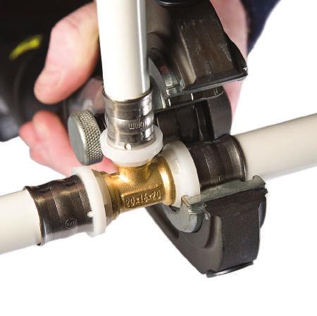
33 TUCSON MOTORISED VALVES 5 Year Warranty Detachable Head Quick Release Power Cable NSAI Approved Instantor Nuts & Olives Robust & Compact Design PRODUCT CODE SIZE CABLE FLOW RATE POWER SUPPLY FUSE/AUX. SWITCH RATING MAX. CLOSE-OFF PRESSURE FAIL MODE WATER TEMP mm - 2 Port CxC 1 Metre 5 Core 4.3m³/hr VAC 50/60HZ 5W 3.0A 250VAC 1.0 bar Normally Closed 5 C to 88 C mm - 2 Port CxC 1 Metre 5 Core 6.8m³/hr VAC 50/60HZ 5W 3.0A 250VAC 0.6 bar Normally Closed 5 C to 88 C Replacement Heads Available Separately Product Code
34 TUCSON AUTOMATIC AIR BOTTLE 2 33

35 TUCSON AUTOMATIC AIR BOTTLE GENERAL INFORMATION 1. Automatic Air Bottle Automatic Air Bottles are used on central heating systems to help keep the system free from any unwanted air which can cause damage to your system. Recommended to be installed on the highest point possible of the system, when the water is circulating it will push the air towards the highest point where the valve will exhaust the unwanted air pockets. Our TUCSON air bottles are also supplied with a non return valve which can be installed with the air bottle for easy maintenace if required. 2. Warranty TUCSON Automatic Air Bottles are sold with a 2 year warranty effective from date of purchase. This warranty covers any manufacturing fault which may cause the air bottle to fail and not perform its designed operations correctly. The warranty is valid on the assumption the following has been applied to the installation: Product installed correctly and used as specified in the instructions. It has been installed by a fully qualified tradesperson. The installation complies with the local building regulations and also any regulations which are relative to automatic air bottle installations. The warranty of the air bottle is invalid if any of the following occurs during installation: The air bottle has been installed to operate for other purposes than what it is designed for. The air bottle is not installed by a fully qualified tradesperson. The air bottle has been installed incorrectly or not to the installation instructions. The air bottle has failed outside of the warranty period. The air bottle has been damaged by outside interference such as bad workmanship or physical damage. Code Max Working Pressure Min Working Pressure Max Temperature 10 Bar 0.2 Bar 120 C Set Up / Maintenance Turn the black cap anti-clockwise when initially filling the system. Once filling is complete turn the cap to its original position. DO NOT remove the cap whilst the system is running. Inspect the air bottle regularly. The system must be cold and de-pressurised when maintenance is being carried out. Remove the air bottle from the non-return valve to avoid system losses when carrying out any maintenance. 34


36 35


 Pipe")


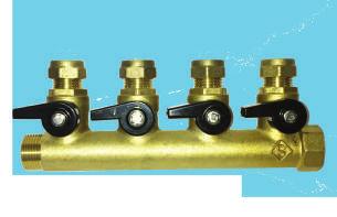

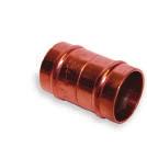
37 INSTANTOR PRESS-FIT FITTINGS INSTANTOR PRESS-FIT FITTINGS Straights Tees Elbows IP10 Straight Coupler IP10 Straight Reducer IP18 Equal Tee IP18 Reducing Tee IP15 Elbow IP16 Elbow IP11 Straight Coupler M.I x Pipe IP12 Straight Coupler F.I x Pipe IP 30 TEE IP17 Elbow F.I x Pipe IP19 Wallplate Elbow Sundry Fittings Brass Manifold IP51 Stop End IP20 Nut And Insert To Copper Compression Tools & Accessories Brass Manifolds (With Adaptors) Brass Manifolds With Iso Valves (And Adaptors) Pipe Reamer Pipe Cutter TH Jaws Press Gun REMS Mini Press Gun 14.4V Battery Complete Set INSTANTOR PEX-AL-PEX PIPE Instantor Pex-Al-Pex Pipe Coils Instantor Pex-Al-Pex Insulated Pipe 36


38 PRODUCTS ALSO INCLUDE... Immersion Heaters Compression Fittings Kitchen & Bathroom Taps Solder Ring & Endfeed Fittings Thermostatic Radiator Valve Packs Superior Plumbing Products 37
KQ Series. Multistage Booster Pump System. Installation Manual. ISO 9001 Certified KQ200/400 KQ800
 KQ Series Multistage Booster Pump System Installation Manual KQ200/400 KQ800 ISO 9001 Certified Description The KQ series booster pump is an all-in-one compact and reliable automatic multistage centrifugal
HORIZONTAL MULTISTAGE CENTRIFUGAL PUMP
 HORIZONTAL MULTISTAGE CENTRIFUGAL PUMP WWPPCHLFT260 Instructions WWPPCHLFT260_Horizontal Multistage Centrifugal Pump_IB.indd 1 READ THIS MANUAL CAREFULL BEFORE INSTALL, START THE PUMP 1. Suction 2. Plug
LC Series - Light Commercial Pump Station Installation and Operation Manual
 LC Series - Light Commercial Pump Station Installation and Operation Manual Please keep this manual with the pump station Content Rain Bird LC Series Overview... Safety Instruction... Operation... 3 Pump
CROWN WATER HEATERS CPU10 - CPU15 CPOS10 - CPOS15
 CROWN WATER HEATERS CPU10 - CPU15 CPOS10 - CPOS15 COMPACT PLUS 10 and 15 Litre Unvented Under and Over Sink Water Heater INSTALLATION AND USER GUIDE 1 DIMENSIONS 10L - 250mm 15L - 310mm 100mm 80mm 410mm
SELF-PRIMING JET PUMPS
 SS Anti-Rust SS Shaft Copper & Cold-rolled SELF-PRIMING JET PUMPS CONTENTS 1. Applications.... Model Description.... Technical Data... 4. Implementation Standards... 5. Safety Precautions... 6. Product
SSA Serie. Features. Model code. Applications. Performance Curves. Operation Conditions. Materials
 The SSA series is an All-in-One self-priming silent booster pump, the compact design combined pressure tank, pressure switch, flow switch and full protection controller, moreover, the evolutional flow
NON-SUBMERSIBLE WATER PUMP
 NON-SUBMERSIBLE WATER PUMP MODEL NO: CEB103 PART NO: 7230327 OPERATION & MAINTENANCE INSTRUCTIONS LS0114 INTRODUCTION Thank you for purchasing this CLARKE Water Pump, which is a general purpose pump, suitable
TQ Series. Electronic Control Pump Instruction Manual. 50Hz. ISO 9001 Certified Walrus Pump Co., Ltd.
 TQ Series Electronic Control Pump Instruction Manual 50Hz ISO 9001 Certified Walrus Pump Co., Ltd. EC Declaration of Conformity Manufacturer: Walrus Pump Co., Ltd. Address: No. 83-14, Dapiantou, Sanjhih
VADA - V80-H PRODUCT OVERVIEW CONSTRUCTION USAGE LIMITATIONS MOTOR WARRANTY
 PRODUCT OVERVIEW The VADA horizontal multistage centrifugal pumps combine the functional benefits of centrifugal pumps and the practical benefits of self priming pumps. They warrant high hydraulic and
V80-H Multistage Pump Instruction Manual
 V80-H Multistage Pump Instruction Manual PRODUCT OVERVIEW The VADA horizontal multistage centrifugal pumps combine the functional benefits of centrifugal pumps and the practical benefits of self priming
IMPORTANT SAFETY INSTRUCTIONS READ AND FOLLOW ALL INSTRUCTIONS SAVE THESE INSTRUCTIONS. Table of Contents WARNING.
 Eagle Pump Owners Manual IMPORTANT SAFETY INSTRUCTIONS READ AND FOLLOW ALL INSTRUCTIONS SAVE THESE INSTRUCTIONS Table of Contents SECTION I. INSTALLATION... 2 SECTION II. OPERATION & MAINTENANCE... 2 SECTION
Manual / Handbuch Spare parts list / Ersatzteilliste
 Manual / Handbuch Spare parts list / Ersatzteilliste Equipment Imp.-Exp. GmbH Zitterpappelweg 9 D - 22391 Hamburg Tel.: + 49 40 60009468-0 Fax: + 49 40 536 75 01 E - M a i l : i n f o @ w e s c o - n a
APPLICATIONS. For the accelerated circulation of hot water in heating circuits with duty point optimisation
 OPERATING RANGE Flow rate of up to m /h Manometric head of up to m Max. operating pressure bar Min. intake pressure, bar at 9 C Water temperature range + at + C * EEI-Part, * for a ambient temperature
SELF-PRIMING CENTRIFUGAL PUMPS BMLS-M & BMLS-H
 SELF-PRIMING CENTRIFUGAL PUMPS BMLS-M & BMLS-H INSTALLATION, OPERATION & MAINTENANCE INSTRUCTIONS HP Phase Medium Head High Head 3 1 BMLS 300 M BMLS 300 H 3 3 BMLS 300 M3 BMLS 300 H3 5 1 BMLS 500 M BMLS
489 & 490 Series CAST IRON UNITS BRONZE UNITS STAINLESS STEEL UNITS MAINTENANCE. Figure 1 - Mechanical Seal Replacement
 Please read and save this Repair Parts Manual. Read this manual and the General Operating Instructions carefully before attempting to assemble, install, operate or maintain the product described. Protect
SUPPLEMENTARY INSTRUCTIONS
 www.burcam.com 2190 Dagenais Blvd.West TEL: 514.337.4415 LAVAL (QUEBEC) FAX: 514.337.4029 CANADA H7L 5X9 info@burcam.com SUPPLEMENTARY INSTRUCTIONS MODEL 450475 Dear consumer, We thank and congratulate
COMPASS HIGH-EFFICIENCY WET-ROTOR CIRCULATORS
 COMPASS HIGH-EFFICIENCY WET-ROTOR CIRCULATORS INSTALLATION AND OPERATING INSTRUCTIONS File No: 10.895 Date: march 8, 014 Supersedes: 10.895 Date: december 10, 013 1.0 Symbols used in this document 1.0
The Classeq under counter range
 Installation & Operators Manual The under counter range Part number 902.0011 Revision C Effective date January 2010 Language English Glasswashers Eco 1 Eco 2 Eco 3 Duo 2 Duo 3 Dishwasher Hydro 500 Hydro
TIDALWAVE I/G POOL PUMP INSTRUCTION MANUAL
 TIDALWAVE I/G POOL PUMP INSTRUCTION MANUAL READ THIS MANUAL CAREFULLY BEFORE USING YOUR PUMP 88 PUMP PARTS BREAKDOWN REF # Order # Mfr # Description 1 NEP4 AC 348 Lid Knobs NEP AC 380 Strainer Lid 3 NEP6
ECONO FLO 2.7HP VARIABLE SPEED PUMP OWNER S MANUAL
 ECONO FLO 2.7HP VARIABLE SPEED PUMP OWNER S MANUAL IMPORTANT SAFETY INSTRUCTIONS READ AND FOLLOW ALL INSTRUCTIONS SAVE THESE INSTRUCTIONS WARNING: Before installing this product, read and follow all warning
Acquaer Ltd. H-4900, Fehérgyarmat, Szatmári út 11. CENTRIFUGAL PUMP Instruction Manual ACm60 / ACm75 / ACm150 / ACm150B2
 CENTRIFUGAL PUMP Instruction Manual ACm60 / ACm75 / ACm150 / ACm150B2 Congratulations on your purchase of a LEO Centrifugal Pump It is important that you read, fully understand and observe the following
GRUNDFOS INSTRUCTIONS. Sololift2 C-3. Installation and operating instructions
 GRUNDFOS INSTRUCTIONS Sololift2 C-3 Installation and operating instructions English (US) English (US) Installation and operating instructions Original installation and operating instructions. CONTENTS
OWNERS GUIDE TO INSTALLATION AND OPERATION
 OWNERS GUIDE TO INSTALLATION AND OPERATION SPM SERIES HIGH POWER CENTRIFUGALS READ THESE INSTRUCTIONS CAREFULLY Read these installation instructions in detail before installing your pump. Be sure to check
VERTICAL GLANDLESS PUMP
 VERTICAL GLANDLESS PUMP INSTALLATION, OPERATION AND MAINTENANCE MANUAL INDEX Sl.No CONTENTS Page No. 1 Introduction 02 2 Unpacking 04 3 Installation procedure for VGP (Pump dispatched without motor) 07
SERVICE MANUAL. 300 Series Motorized 35650, 35651, 35652, 36750, 36751, and Model
 Section: MOYNO 500 PUMPS Page: 1 of 4 Date: March 1, 1998 SERVICE MANUAL MOYNO 500 PUMPS 300 Series Motorized 35650, 35651, 35652, 36750, 36751, and 36752 Model DESIGN FEATURES Housing: Cast iron/316 SS
CC Series VACUUM PUMPS
 CC Series VACUUM PUMPS OPERATING MANUAL Thank you for selecting a Javac select product! Please read this operation manual carefully before use. Only suitably qualified personnel should operate this equipment.
Pump WaterVISE, FloVISE
 General information It is important that this manual is read carefully by the user and the installer in order to ensure proper functioning and lifespan of the pump. Pahlen pumps are manufactured in accordance
ECONO FLO VSA 165 VARIABLE SPEED PUMP OWNER S MANUAL
 ECONO FLO VSA 165 VARIABLE SPEED PUMP OWNER S MANUAL IMPORTANT SAFETY INSTRUCTIONS READ AND FOLLOW ALL INSTRUCTIONS SAVE THESE INSTRUCTIONS WARNING: Before installing this product, read and follow all
SMF PUMP OWNER S MANUAL
 SMF PUMP OWNER S MANUAL IMPORTANT SAFETY INSTRUCTIONS READ AND FOLLOW ALL INSTRUCTIONS SAVE THESE INSTRUCTIONS WARNING: Before installing this product, read and follow all warning notices and instructions
13-1. Temperature Regulator
 -1 Step 0 Type/Structure/Features Please refer to this for type, structure and features of. Step 1 Selection Please look at the ID chart to choose the right products depending on the intended uses. Details
INSTRUCTION- AND MAINTENANCE MANUAL FOR ELECTROMAGNETIC AIR PUMP JDK-60, JDK-80, JDK-100, JDK-120
 INSTRUCTION- AND MAINTENANCE MANUAL FOR ELECTROMAGNETIC AIR PUMP MODEL : JDK-60, JDK-80, JDK-100, JDK-120 - release 29.01.2014 - We thank you for purchasing our air pump. Prior to use, it is kindly requested
Hodge Clemco Ltd. MJC Mini Cartridge Filters Owners Manual. TSOM 556 Date of issue 13/07/04. Hodge Clemco Ltd
 1 MJC Mini Cartridge Filters Owners Manual TSOM 556 Date of Issue: 13.07.04 Orgreave Drive, Sheffield South Yorkshire. S13 9NR Tel:0114 254 0600 Fax: 0114 2540250 Email:sales@hodgeclemco.co.uk www.hodgeclemco.co.uk
MECHANICAL SEAL REPLACEMENT UNPACKING MAINTENANCE. Figure 1 & 2 - Mechanical Seal Replacement
 Please read and save this Repair Parts Manual. Read this manual and the General Operating Instructions carefully before attempting to assemble, install, operate or maintain the product described. Protect
KRS data sheet parts list exploded view dimensional drawing sectional drawing performance curve. parts list as Excel-spreadsheet
 KRS822-50 data sheet parts list exploded view dimensional drawing sectional drawing performance curve parts list as Excel-spreadsheet Heltorfer Str.6 40472 Düsseldorf Germany Tel.: +49-2-479373 Fax: +49-2-479429
Installation & Operators Manual
 Installation & Operators Manual Eco, Hydro and Duo under counter range Part number 902.0011 Revision A Installation and Operation instructions For Classeq under counter range of glass and dishwashers.
Cleaning unit for coolant. :_decftez`_>r_fr] Book No.: V2
![Cleaning unit for coolant. :_decftez`_>r_fr] Book No.: V2](/thumbs/90/104143238.jpg "Cleaning unit for coolant. :_decftez`_>r_fr] Book No.: V2") Cleaning unit for coolant :_decftez`_>r_fr] Book No.: 1271526-02 V2 Alfa Laval Separation AB Separator Manuals, dept. SKEL S-147 80 Tumba, Sweden Telephone: +46 8 53 06 50 00 Telefax: +46 8 53 03 10 40
Cleaning unit for coolant :_decftez`_>r_fr] Book No.: 1271526-02 V2 Alfa Laval Separation AB Separator Manuals, dept. SKEL S-147 80 Tumba, Sweden Telephone: +46 8 53 06 50 00 Telefax: +46 8 53 03 10 40
Hot Water Circulator Pump LRP
 Hot Water Circulator Pump LRP Contents. Introduction.... Safety Instruction... 3.Product Structure... 4 4. Technical Parameters... 7 5. Precautions... 8 9. Troubleshooting Disconnect power supply before
Specifications Information and Repair Parts Manual 316A-95, 316B-95, 393A-95, 393B A-95 thru 394D-95, 399A-95
 Specifications Information and Repair Parts Manual 316A-95, 316B-95, 393A-95, 393B-95 394A-95 thru 394D-95, 399A-95 Please read and save this Repair Parts Manual. Read this manual and the General Operating
INSTALLATION, COMMISSIONING AND OPERATING MANUAL
 INSTALLATION, COMMISSIONING AND OPERATING MANUAL 1 YTBV-D-CE42_0109 CONTENT Available models and capacities Supplier information Warranty Safety Emergency stops/ shutdowns About this manual Models Physical
Instructions for installation and use English. More documents on: H B /09
 TM Instructions for installation and use English EN More documents on: www.zodiac-poolcare.com H0538700.B - 2015/09 Read this manual carefully before installing, maintaining or repairing this appliance!
569, 570, 571, 572 Series
 Please read and save this Repair Parts Manual. Read this manual and the General Operating Instructions carefully before attempting to assemble, install, operate or maintain the product described. Protect
Installation, operation and care Wall-mounted electric boiler MP THL nr. - rev 02
 Installation, operation and care Wall-mounted electric boiler MP 4 150206 THL nr. - rev 02 Contents Notes... 3 Safety and handling... 4 Operation... 5 Technical data... 6 Pipe installation... 8 System
Panel Fan Series Operators Manual (Galvanized and Polymer)
") Panel Fan Series Operators Manual (Galvanized and Polymer) Galvanized Panel Fan with Three Wing Blade IMPORTANT: READ AND SAVE THESE INSTRUCTIONS Read all instructions carefully before attempting to assemble,
Panel Fan Series Operators Manual (Galvanized and Polymer) Galvanized Panel Fan with Three Wing Blade IMPORTANT: READ AND SAVE THESE INSTRUCTIONS Read all instructions carefully before attempting to assemble,
1 Declaration of conformity
 ENERGY SAVING 1 Declaration of conformity We Taco Italia S.r.l. declare under our sole responsibility that the family of products ENERGY SAVING to which this declaration relates are in conformity with
APW PSI PRESSURE WASHER
 APW5001 1300 PSI PRESSURE WASHER 1300 PSI PRESSURE WASHER Please carefully read this manual which has been specifically designed to provide all the necessary information for the correct use of the machine,
MECHANICAL SEAL REPLACEMENT UNPACKING MAINTENANCE. Figure 1 & 2 - Mechanical Seal Replacement
 Please read and save this Repair Parts Manual. Read this manual and the General Operating Instructions carefully before attempting to assemble, install, operate or maintain the product described. Protect
CPE RANGE PUMPS CPE RANGE PUMPS. MODEL Nos: CPE15A1 15A3 20A1 20A3 30A1 30A3 PART Nos:
 CPE RANGE PUMPS CPE RANGE PUMPS MODEL Nos: CPE15A1 15A3 20A1 20A3 30A1 30A3 PART Nos: 7120305 7120310 7120315 7120320 7120325 7120330 OPERATION & MAINTENANCE INSTRUCTIONS GC0514 Contents Specifications...
"S" SERIES IMMERSIBLE PUMP OWNER'S MANUAL INSTALLATION OPERATION PARTS Models S12 S16
 Webster Pumps "S" SERIES IMMERSIBLE PUMP OWNER'S MANUAL INSTALLATION OPERATION PARTS Models S12 S16 PLEASE READ THE FOLLOWING INFORMATION PRIOR TO INSTALLING AND USING Webster PUMPS or HAYWARD VALVES,
Closomat Lima Vita installation & user guide
 Closomat Lima Vita installation & user guide design manufacture supply install service recycle Technical data The Closomat toilet MUST be installed by a competent or qualified person. Explanation of symbols
INSTALLATION & OPERATING INSTRUCTIONS
 INSTALLATION & OPERATING INSTRUCTIONS WARNING RISK OF ELECTRIC SHOCK. CONNECT ONLY TO A CIRCUIT PROTECTED BY A GROUND-FAULT CIRCUIT-INTERRUPTER. THE UNIT SHOULD BE INSTALLED BY A QUALIFIED SERVICE REPRESENTATIVE.
GRUNDFOS DATA BOOKLET. Grundfos COMFORT. Circulator pumps. 50/60 Hz
 GRUNDFOS DATA BOOKLET Circulator pumps 50/60 Hz 2 Product range 2. Product range UP(S) COMFORT, 50/60 Hz Pump type 24-hour timer Supplied with Dimensions Accessories Data sheet Thermostat Isolating valve
CHAMPION PUMP OWNER S MANUAL
 CHAMPION PUMP OWNER S MANUAL IMPORTANT SAFETY INSTRUCTIONS READ AND FOLLOW ALL INSTRUCTIONS SAVE THESE INSTRUCTIONS WARNING: Before installing this product, read and follow all warning notices and instructions
Unvented Electric Water Heater 10/15 litre Undersink
 Unvented Electric Water Heater 10/15 litre Undersink Fitting Instructions and User Guide 1 CONTENTS SECTION PAGE 1.0 INTRODUCTION 2 2.0 TECHNICAL SPECIFICATION 3 3.0 INSTALLATION 4 4.0 COMMISSIONING 9
CENTRIFUGAL PUMPS OPERATING INSTRUCTIONS
 CENTRIFUGAL PUMPS OPERATING INSTRUCTIONS Please leave this instruction booklet with the pump as it contains maintenance and safety information (Original Instructions) MODELS Kennet K7-2 Kennet K9-2 Kennet
EBAC MODEL WM150 INDUSTRIAL DEHUMIDIFIER OWNER S MANUAL
 EBAC MODEL WM150 INDUSTRIAL DEHUMIDIFIER OWNER S MANUAL WM150 OWNERS MANUAL Page 1 of 9 INTRODUCTION Designed for a wide range of applications, the WM150 is a rugged, industrial unit, which utilizes an
569, 570, 571, 572 Series
 Please read and save this Repair Parts Manual. Read this manual and the General Operating Instructions carefully before attempting to assemble, install, operate or maintain the product described. Protect
MD SERIES Instruction Manual
 IWAKI Magnetic Drive Pump MD SERIES Instruction Manual Read this manual before use of product Thank you for having selected the Iwaki Magnetic Drive Pump MD series. This manual deals with the correct handling
489G DESCRIPTION CAST IRON UNITS BRONZE UNITS 316 STAINLESS STEEL UNITS. Maintenance. General Safety Information for 12 Volt DC Power
 Please read and save this Repair Parts Manual. Read this manual and the General Operating Instructions carefully before attempting to assemble, install, operate or maintain the product described. Protect
SUBMERSIBLE WATER PUMP. Model Nos. CSE1 - CSE1A - CSE2 - CSE2A CSD3- -CSD3A CSV1A - CSV2 - CSV2A - CSW1A OPERATING & MAINTENANCE INSTRUCTIONS
 1117 SUBMERSIBLE WATER PUMP Model Nos. CSE1 - CSE1A - CSE2 - CSE2A CSD3- -CSD3A CSV1A - CSV2 - CSV2A - CSW1A OPERATING & MAINTENANCE INSTRUCTIONS GUARANTEE This product is guaranteed against faults in
Installation and Commissioning Instructions FMU3 Floor Mixing Unit with Grundfos UPM3 Pump
 Installation and Commissioning Instructions FMU3 Floor Mixing Unit with Grundfos UPM3 Pump Reduced Installation time Precision regulation Minimal tooling required 100% tested prior to packaging High quality
A Series. 60 Hz. Horizontal Multistage Centrifugal Pumps AHC/AHI, AHBI/AHBS ISO Vol. PIAH-18091
 A Series ISO-9 orizontal Multistage Centrifugal Pumps AC/AI, ABI/ABS z APEC Pump ENTERPRISE CORP. 3F.,No.39,Sec. Mingzhi Rd., Taishan Dist.,New Taipei City 3,Taiwan. Tel : +--937 Fax: +--97 www.apecpump.com
User Guide. Fixed Flow Pumps FOR SUBMERSIBLE OR INLINE USE FOR PUMP MODELS # # # # # # # # #728333
 User Guide Fixed Flow Pumps FOR SUBMERSIBLE OR INLINE USE 100 #728492 1056 #728320 FOR PUMP MODELS 185 264 396 633 #728300 #728305 #728310 #728315 1267 #728325 1584 #728330 2245 #728333 Fixed Flow Pumps
WALLACE MAXIPUMP 3000, 5000, 6000 and HYDROJET 30P, 30C, 140 AND HJ400 INSTALLATION AND MAINTENANCE INSTRUCTIONS
 6 th June 2006 Page 1 WALLACE MAXIPUMP 3000, 5000, 6000 and HYDROJET 30P, 30C, 140 AND HJ400 INSTALLATION AND MAINTENANCE INSTRUCTIONS Please read and follow all these instructions carefully before proceeding
"S" SERIES IMMERSIBLE PUMP OWNER'S MANUAL INSTALLATION OPERATION PARTS Models S2 S4 S5 SS6 SS7 S8
 Webster Pumps "S" SERIES IMMERSIBLE PUMP OWNER'S MANUAL INSTALLATION OPERATION PARTS Models S2 S4 S5 SS6 SS7 S8 PLEASE READ THE FOLLOWING INFORMATION PRIOR TO INSTALLING AND USING Webster PUMPS or HAYWARD
T-Series Air Conditioner T20 Model
 INSTRUCTION MANUAL T-Series Air Conditioner T20 Model Protecting Electronics. Exceeding Expectations. McLean Cooling Technology 11611 Business Park Blvd N Champlin, MN 55316 USA Tel 763-323-8200 Fax 763-576-3200
MODEL E
 www.burcam.com 2190 Dagenais Blvd. West TEL: 514.337.4415 LAVAL (QUEBEC) FAX: 514.337.4029 CANADA H7L 5X9 info@burcam.com Your pump has been carefully packaged at the factory to prevent damage during shipping.
OPERATION & MAINTENANCE INSTRUCTIONS
 SUBMERSIBLE PUMPS MODEL NO: PSV3A, PSV4A, PSSV2A & PVP11A PART NO: 7236042, 7236044, 7236050 & 7236060 OPERATION & MAINTENANCE INSTRUCTIONS ORIGINAL INSTRUCTIONS GC07/17 iss 4 INTRODUCTION Thank you for
AC6 & AC8 HORIZONTAL SERIES Sealed Metallic Centrifugal Pumps Installation and Maintenance Instructions
 AC6 & AC8 HORIZONTAL SERIES Sealed Metallic Centrifugal Pumps Installation and Maintenance Instructions ASSEMBLY PUMPS WITH MOTORS 1. No assembly required. Unpack the pump and motor and examine for any
FSW300 Series Flow Switch
 . FSW300 Series Flow Switch - 2 - Series FSW300 Series FSW300 Table of contents page 0 About this operating manual... 4 1 Device description... 5 1.1 Intended use... 5 1.1.1 Reed contact - Switching of
INSTRUCTIONS FOR INSTALLATION AND MAINTENANCE (GB)
") INSTRUCTIONS FOR INSTALLATION AND MAINTENANCE (GB) Pag. 1 Fig - Fig. - Abb.- Fig.- Fig.- Фиг.- Obr.- Fig.- Εικ. - Joonis - Kuva - Sl. -.ábra - Fig. -.att. - Afbeelding - Fig. - Rys.- Fig.- Fig. - Схема
INSTRUCTIONS FOR INSTALLATION AND MAINTENANCE (GB) Pag. 1 Fig - Fig. - Abb.- Fig.- Fig.- Фиг.- Obr.- Fig.- Εικ. - Joonis - Kuva - Sl. -.ábra - Fig. -.att. - Afbeelding - Fig. - Rys.- Fig.- Fig. - Схема
T-SERIES Air Conditioner. T43 Model INSTRUCTION MANUAL nvent Rev. I P/N
 T-SERIES Air Conditioner T43 Model INSTRUCTION MANUAL Rev. I P/N 10-1008-145 TABLE OF CONTENTS Warranty and Return Policy...2 IMPORTANT NOTICE...2 RECEIVING THE AIR CONDITIONER...3 HANDLING AND TESTING
EVAPORATIVE COOLER PUMPS
 EVAPORATIVE COOLER PUMPS ebmpapst Evaporative Cooler Pump EBMALPHA $144.65 @ 1. metre Head @ 2. metre Head Power Supply 32 litres/min 25 litres/min 24V/1/5Hz Nominal Watts 5 watts Outlet Connection 2mm
Model Series Series
 PumpAgents.com - Click here for Pricing/Ordering Model 36800-Series 36900-Series ELECTRIC WATER SYSTEM PUMPS Automatic Multi-Outlet FEATURES Self-Priming Diaphragm Design Allows Dry Running Built-in Discharge
GRUNDFOS DATA BOOKLET. Hydro Multi-S. Grundfos booster systems with two or three CM, CMV or CR pumps. 50 Hz
 GRUNDFOS DATA BOOKLET Grundfos booster systems with two or three CM, CMV or CR pumps 50 Hz Table of contents 1. Product introduction 3 2. Performance range 4 with CM pumps 4 with CMV pumps 4 with CR pumps
SUBMERSIBLE DIRTY WATER PUMP
 SUBMERSIBLE DIRTY WATER PUMP MODEL NO: DWP100A, DWP150A, DWP200A PART NO: 7230098, 7230099, 7230100 OPERATION & MAINTENANCE INSTRUCTIONS ORIGINAL INSTRUCTIONS LS1117 - ISS 2 INTRODUCTION Thank you for
CENTRIFUGAL PUMPS OPERATING INSTRUCTIONS
 CENTRIFUGAL PUMPS OPERATING INSTRUCTIONS Please leave this instruction booklet with the pump as it contains maintenance and safety information (Original Instructions) MODELS This operating manual covers
Model T Professional Series 3/4HP 2 YEAR WARRANTY SEWAGE PUMP
 Model T00405 REPAIR PARTS REF. PART DESCRIPTION REF. PART DESCRIPTION 1 450331 Strainer 2 450332 Oil cover "O" ring 3 400447 Impeller 4 450333 Pump casing 5 400450 Oil cover 6 400449 Oil seal 7 400448
T-SERIES Air Conditioner. T50 Model INSTRUCTION MANUAL nvent Rev. F P/N
 T-SERIES Air Conditioner T50 Model INSTRUCTION MANUAL Rev. F P/N 10-1008-203 TABLE OF CONTENTS Warranty and Return Policy...2 RECEIVING THE AIR CONDITIONER...3 HANDLING AND TESTING THE AIR CONDITIONER...3
30KW ELECTRIC FAN HEATER
 30KW ELECTRIC FAN HEATER MODEL NO: DEVIL 7030 PART NO: 6935458 OPERATION & MAINTENANCE INSTRUCTIONS LS0615 INTRODUCTION Thank you for purchasing this CLARKE product. Before attempting to use this product,
Models Series Series
 Models 31800-Series 31801-Series INDUSTRIAL DIAPHRAGM PUMPS 4 GPM/15 LPM FEATURES Self-Priming Easy Installation Can run dry without damage Low Amp Draw Flow to 4 GPM/15 LPM Compact Size Thermal Overload
rev3 INSTALLATION & OPERATION MANUAL OIL CIRCULATING HEATING SYSTEM MODEL OSM
 216279-000 rev3 INSTALLATION & OPERATION MANUAL OIL CIRCULATING HEATING SYSTEM MODEL OSM IDENTIFYING YOUR SYSTEM IOM216279-000 The HOTSTART heating system is designed to heat fluids for use in marine
Room Air Conditioner Service and Parts Manual
 Cool Dry Temp Mode Room Air Conditioner Service and Parts Manual F Fan Speed hr Timer 0n 0ff Money Saver Fan Only Auto Swing Power CP06 CP08 93011401_01 CONTENTS 1. PREFACE 1.1 SAFETY PRECAUTIONS...2 1.2
AZN ATEX INSTALLATION AND MAINTENANCE
 ZerAx AZN ATEX INSTALLATION AND MAINTENANCE 924714-0 English 924714-0 GB ZerAx axial flow fans type AZN ATEX Installation and maintenance 1. Application 2. Handling 2.1 Marking 2.2 Weight 2.3 Temperature
T-Series Air Conditioner T53 Model
 INSTRUCTION MANUAL T-Series Air Conditioner T53 Model Protecting Electronics. Exceeding Expectations. McLean Cooling Technology 11611 Business Park Blvd N Champlin, MN 55316 USA Tel 763-323-8200 Fax 763-576-3200
CENTRIFUGAL FAN IN SCROLL CASING. Helix S-Vent OPERATION MANUAL
 CENTRIFUGAL FAN IN SCROLL CASING Helix S-Vent EN OPERATION MANUAL Helix / S-Vent www.blaubergventilatoren.de CONTENTS CONTENTS 3 Introduction 3 Use 3 Delivery set 4 Technical data 10 Safety requirements
Sanipack is a compact pump/macerator specially designed to take the waste from a wall hung or back to wall WC pan.
 1. escription Sanipack is a compact pump/macerator specially designed to take the waste from a wall hung or back to wall WC pan. I The Sanipack will pump away the waste from a WC, washbasin and shower.
T-SERIES Air Conditioner. T20 Model INSTRUCTION MANUAL nvent Rev. C P/N
 T-SERIES Air Conditioner T20 Model INSTRUCTION MANUAL Rev. C P/N 89114993 TABLE OF CONTENTS Warranty and Return Policy... 2 IMPORTANT NOTICE... 2 RECEIVING THE AIR CONDITIONER... 3 HANDLING AND TESTING
CR A-F-A-E-HQQE 3x400/ HZ
 GRUNDFOS DATA BOOKLET CR32--2 A-F-A-E-HQQE 3x/69 5 HZ Grundfos pump 9612212 Thank you for your interest in our products. Please contact us for more information, or visit our website https://www.lenntech.com/grundfos/crfam/9612212/cr-32--2-a-f-a-e-hqqe.html
Patterson/AMT Inline Circulator Pump Refer to pump manual for General Operating and Safety Instructions.
 Please read and save this Repair Parts Manual. Read this manual and the General Operating Instructions carefully before attempting to assemble, install, operate or maintain the product described. Protect
GRUNDFOS DATA BOOKLET UPS2. Circulator pumps. 50/60 Hz
 GRUNDFOS DATA BOOKLET UPS2 Circulator pumps 50/60 Hz UPS2 Table of contents 1. Product introduction 3 Type key.................................................................................... 3 Performance
568X, 587X, 588X Series
 Please read and save this Repair Parts Manual. Read this manual and the General Operating Instructions carefully before attempting to assemble, install, operate or maintain the product described. Protect
Technical Product Guide
 FMU - Floor Mixing Unit Boxed set pre-assembled for immediate installation: The FMU Floor Mixing Unit integrates both temperature and flow management, making the single piece unit very easy to install,
T-Series Air Conditioner T15 Model
 INSTRUCTION MANUAL T-Series Air Conditioner T15 Model Protecting Electronics. Exceeding Expectations. McLean Cooling Technology 11611 Business Park Blvd N Champlin, MN 55316 USA Tel 763-323-8200 Fax 763-576-3200
2 SPEED PUMP INSTRUCTION MANUAL READ THIS MANUAL CAREFULLY BEFORE USING YOUR 2 SPEED PUMP
 2 SPEED PUMP INSTRUCTION MANUAL READ THIS MANUAL CAREFULLY BEFORE USING YOUR 2 SPEED PUMP 8308 PUMP PARTS BREAKDOWN Ref # Part # Manf. # Descrip on 1 NEP2134 AC 81361 PUMP LID 2 NEP2135 AC 81396 PUMP LID
STOP. SAFETY INFORMATION Please read and understand this entire manual before attempting to assemble, operate or install the product.
 STOP Power supply required Questions, problems, missing parts? Before returning to your retailer, call our customer service department at 1-800-742-5044, 7:30 a.m. - 5 p.m., EST, Monday - Friday. 115 volts
This label warns for risk of electrical shock when failing to observe.
 MANUAL horizontal centrifugal pumps MB series ic drive SB series mechanical seal 1. Introduction 2. Safety precautions 3. Receipt 4. Installation / Operation and Maintenance 4.1 Installation 4.2 Operation
AHW AHW(S) Hot water circulator pump INSTALLATION AND OPERATING INSTRUCTIONS HIGH-EFFICIENCY BLDC-MOTOR CIRCULATORS
 Hot water circulator pump INSTALLATION AND OPERATING INSTRUCTIONS HIGH-EFFICIENCY BLDC-MOTOR CIRCULATORS") AHW AHW(S) Hot water circulator pump INSTALLATION AND OPERATING INSTRUCTIONS HIGH-EFFICIENCY BLDC-MOTOR CIRCULATORS EC Declaration of Conformity Declare that machinery described: AHW,AHW(S) Hot water circulator
AHW AHW(S) Hot water circulator pump INSTALLATION AND OPERATING INSTRUCTIONS HIGH-EFFICIENCY BLDC-MOTOR CIRCULATORS EC Declaration of Conformity Declare that machinery described: AHW,AHW(S) Hot water circulator
Elite Primer Baldor Series External Pond Pump
 Elite Primer Baldor Series External Pond Pump ( 5250PPB21, 6440PPB23, 7550PPB26, 9600PPB28) Installation and User s Guide IMPORTANT SAFETY INSTRUCTIONS, READ AND FOLLOW ALL INSTRUCTIONS. SAVE THESE INSTRUCTIONS
INSTRUCTION AND REPAIR MANUAL
 SECTION 6 ITEM 390 DATED JANUARY 2003 SUPERSEDES SECTION 6 ITEM 390 DATED OCTOBER 2000 INSTRUCTION AND REPAIR MANUAL SERIES 390 6 The 390 Series is a superior commercial Multi-Stage Vertical In-Line Centrifugal
15-BER3. parts list as Excel-spreadsheet. Tsurumi Europe GmbH
 5-BER3 data sheet parts list exploded view dimensional drawing free standing type dimensional drawing TOS-type sectional drawing free standing type sectional drawing TOS-type performance curve parts list