BIO-SELECT BIO-SELECT PLUS INSTALLATION, USER AND MAINTENANCE MANUAL
|
|
|
- Winifred Small
- 6 years ago
- Views:
Transcription

1 STEEL BOILER FOR HEATING BIOMASS SOLID FUEL BIO-SELECT BIO-SELECT PLUS INSTALLATION, USER AND MAINTENANCE MANUAL COD EN.02
2 THANK YOU FOR PURCHASING THIS PRODUCT! On behalf of LASIAN Tecnología del Calor (Heat Technology) S. L. thank you for trusting us, and you choose the Bioselect / Bioselect Plus LASIAN boiler. Now you have a biomass boiler exclusively for home. Please read the advice and warnings in this manual, as it will furnish important information regarding the safe installation, use and maintenance carefully. The installation of the boiler Bioselect and Bioselect Plus must be performed by qualified personnel, following the manufacturer's instructions and in accordance with current standards. Improper installation may cause damage, hence the importance of this document is an integral part of the product. The manufacturer is not responsible for the misuse of it. 1
3 INDEX INTRODUCTION. 4 TECHNICAL SPECIFICATIONS.. 5 DESCRIPTION Iron body 7 Burner and fuel feeder.. 7 Boiler regulation and control elements.. 10 SAFETY WARNINGS LOCATION. 12 ASSEMBLY 13 Boiler/Enclosures OPERATING INSTRUCTIONS Power regulation 20 Combustion air regulation Ignition / Shutdown 21 MAINTENANCE. 21 Regular inspections.. 21 Boiler cleaning MODEL REPLACEMENTS AND COMPONENTS.. 23 WARRANTY DECLARATION OF CONFORMITY
4 INTRODUCTION Automatic biomass boilers from Lasian BIO-SELECT and BIO-SELECT PLUS Series have been designed for the production of hot water for heating through the use of solid fuel as pellets, almond shell and olive pulp and pits. In order to use other solid fuels, please get in touch with our technical department. They are available in three models with outputs of 35, 50 and 65 kw. They meet the requirements of the standard: UNE EN 303/5. Heating boilers. Part 5. Heating boilers for solid fuels, manually and automatically stoked, nominal heat output of up to 500 kw. Maximum operating pressure of the boilers BIO-SELECT Series is 3 bar. They consist of the following components: - Steel boiler body. - Fuel tank and auger feeder. - Burner and fan. - Igniter (only BIO -SELECT PLUS) - Electronic control panel. Their main features are: Automatic operation boiler. Electronic panel for heating systems control. Boiler body made of sheet steel. Adaptable to any fuel tank and with the possibility of placing it on either side of the boiler. Easy operation and minimal maintenance. The internal design of the boiler body ensures a large capacity of exchange between combustion gases and water. High performance with energy efficiency over 85%. Low emissions, minimal environmental impact. Combustion ashes are deposited in the lower part of the boiler where they are collected in a high capacity tray. 3
5 TECHNICAL SPECIFICATIONS Model series BIO -SELECT and BIO-SELECT PLUS can be used with solid fuels such as pellets, almond shell and olive pulp or pits. The use of different fuels results in different power. The experience of each user, depending on the characteristics of the fuel used, its moisture and hot water requirements, will determine the most appropriate adjustment of the boiler. The following tables show the main characteristics of each model of boiler: BIO-SELECT 35 BIO-SELECT 50 BIO-SELECT 65 kw Nominal power kcal / h 30,100 43,000 55,900 kw Minimum useful power kcal / h 8,600 11,180 13,760 Fuel consumption kg / (l.h.v. 4,100 kcal/kg moisture 10%) h Efficiency % Minimum useful power in standby kw 1.5 Fuel consumption in standby kg / h 0.37 Gases temperature C Weight kg Water volume in body l Flue duct diameter mm l 725 Fuel tank capacity kg 470 Autonomy with pellets, olive pits or similar h Dimensions: width x height x depth mm 550X1612X X1640X X1700X1660 Maximum working pressure bar 4 Proof pressure bar 6 Minimum return water temperature C 55 Maximum working temperature C 90 Chimney draught mbar Fumes flow: - at useful nominal power kg / s at minimum useful power kg / s Connection - Impulse 1 H 1-½ H 1-½ H - Return 1 H 1-½ H 1-½ H Power ~ 230 V 50 Hz +T Nominal power used, heating mode W Maximum power used, ignition mode Insulation of electric box IP 65 Fuels must have these characteristics: Particle size: max. 40 mm Calorific value: min kcal/kg Moisture: max. 25% 4
6 BOILER DIMENSIONS MODEL A B C D E F G H I J K L M BIOSELECT "H 1"H Ø150 BIOSELECT /2"H 1-1/2"H Ø180 BIOSELECT /2"H 1-1/2"H Ø180 K heating return L heating one-way M chimney 5
7 DESCRIPTION IRON BODY Boiler body made of steel with vertical fumes passages and automatic cleaning system of these passages. In the ducts used for the passage of combustion gases, there are some retainers that favour the exchange of the heat contained in these gases. The impulse and water return intakes (G 1½ ) are in the back of the boiler. The front of the boiler has a large door for access to the combustion chamber and the ash pan for the purpose of cleaning the shoot and removal of ash. There is also an inspection lid placed on the door for the shoot cleaning of the fumes passages. The body is finished with a heat resistant coating to prevent thermal radiations and with the exterior finish of the enclosure sheets to give it cleanliness, pleasant visual aesthetics and protection against burns. BURNER AND FUEL FEEDER The burner has a longitudinal concave shape which receives the fuel to burn from an auger which is fed, in turn and with a hose, by another auger connected to the fuel hopper. There is a ceramic or stainless steel piece (depending on the models) installed over the burner. The air supply is provided by a fan coupled to the burner and supplied with a control for the inflow. The operation of these components is programmed by the electronic control of the boiler. The burner arrangement prevents material from the accumulation of burned material and the risk of a build-up of the burned material. This material is continuously replaced by new one. Burned material does not adhere to the walls of the combustion chamber but is stored in the tray provided for this purpose. Combustion is therefore safe and more notably, due to the characteristics of the material transport lines, heat transfer to the fuel tank becomes impossible. 6
8 MANUAL IGNITION BURNER (15010) Mark Units Cod DESCRIPTION Manual ignition burner 35/50 kw Manual ignition burner 65 kw Burner stainless baffler Bioselect 35/ Burner stainless baffler Bioselect Burner auger x6x70 flat key Motor-reducer set Special reducer flange Fan Fan seal Burner joint Bioselect 35/ Burner joint Bioselect DIN 934 M-8 6 Zn nut DIN 933 M-6x Zn screw DIN 933 M-8x Zn screw DIN 933 M-10x Zn screw DIN 125A Ø6 Zn flat washer DIN 125A Ø8 Zn flat washer DIN 125A Ø10 Zn flat washer DIN 934 M-6 6 Zn nut DIN 9021 Ø8 Zn flat washer 7
9 ELECTRONIC IGNITION BURNER (15011) Mark Units Cod DESCRIPTION Automatic ignition burner 35/50 kw Automatic ignition burner 65 kw Burner stainless baffler Bioselect 35/ Burner stainless baffler Bioselect Burner auger x6x70 flat key Motor-reducer set Special reducer flange Fan Fan seal Burner joint Bioselect 35/ Burner joint Bioselect DIN 934 M-8 6 Zn nut DIN 933 M-6x Zn screw DIN 933 M-8x Zn screw DIN 933 M-10x Zn screw DIN 125A Ø6 Zn flat washer DIN 125A Ø8 Zn flat washer Bluing DIN 975 M threaded rod DIN 125A Ø10 Zn flat washer 8
10 DIN 934 M-6 6 Zn nut 19 1 mt Ø40 mm interior flexible transparent tube for air M8x30 Isophonic clamp Ø40 tube holding Heat gun ignition Heat gun ignition cable Air adapter Igniter air refrigeration intake coil DIN 9021 Ø8 Zn flat washer de 8 mm auger washer BOILER REGULATION AND CONTROL ELEMENTS ELECTRONIC REGULATOR It will assume automatic control on the basis of the inserted parameters, permanently taking into account the data from the temperature sensors. It is possible to operate all its elements for maintenance manually and to adjust the parameters of mode as to achieve the best performance in terms of the fuel used. SAFETY THERMOSTAT Pre-installed in the control panel. It is calibrated at 110 ºC in order to prevent any manoeuvre above this temperature. In case of overheating, it will be activated, and the warning light will be illuminate on in the control panel. It is necessary to wait until the temperature returns to normal to proceed with its rearmament. This is done manually by pressing the button protected by a cap-nut. In the event that the safety thermostat goes off repeatedly, it is imperative to disconnect the boiler and fix the existing fault. PRESSURE GAUGE It measures the pressure of the water in the circuit. FAN It is connected to the outside of the burner. The air intake is controlled by a flap installed in the air entrance of the same. ATTENTION To control it appropriately, consult the electronic regulation manual included with the boiler. ANTI-BACKFIRE FLAME THERMOSTAT It is installed in the feeding tube of the burner and its function is to prevent the backfire of the flame in the burner feeder. THERMOSTATIC FLOOD VALVE It is installed at the top of the auger of the fuel tank and it serves to extinguish the fire by water flooding in case of backfire of the flame in the boiler. 9
11 SAFETY PRECAUTIONS Please pay attention to the following instructions before the installation and start-up of the boiler. Do not operate the boiler without a proper installation of the chimney. The chimney is very important for the optimum performance of the boiler and must provide the minimum draught in the table of features according to the model of boiler. This must be made of stainless material, thermally insulated and authorised. The boiler must always work on depression. ATTENTION If fumes are produced during the operation of the boiler, ventilate the room and check the tightness of both boiler and chimney elements. Once verified, if the problem persists, contact the T.A.S. for a solution. Installation must be carried out in accordance with the existing laws and regulations for this type of boilers and always taking care and observing the some minimum safety requirements for the people and buildings where they are placed. Existing regulations on fire protection in buildings will be especially considered. Regulations on ventilation, lighting level, electrical safety, minimum dimensions of the room, distance between machines must be complied to facilitate the maintenance as well as protection against external moisture and the provision of an efficient drainage system. The boiler should be installed in a well-ventilated room with a sufficient air entrance. No boiler will be installed in rooms or areas where flammable or explosive products can be stored. Do not install the boiler in spaces or areas of continuous use of people, rooms, living rooms, halls, etc. The boiler must be installed to ensure that the hydraulic circuit incorporates the security measures for an increase of temperature and water pressure, by including an open expansion tank at the highest point of the house or a closed expansion tank with safety valve calibrated to a pressure of 3 bar. Ensure that the water circulating pump in the installation is continuously running, unless it is controlled by a thermostat of minimum temperature of the water of the boiler. Any deficiency in the electrical installation must be repaired. Monitor and regularly maintain the water in the boiler and installation. ATTENTION Do not take water out of the installation or empty the water from the boiler except in extreme cases of maintenance or repair. Under no circumstances should the water from the boiler be for domestic use. Do not fill the body of the boiler with cold water during operation or when the body is hot, it would cause cracks due to thermal contrast cold-hot. The quality of the water is very important. The recommended water hardness is: 1-3 mol/m3= 5.6º d), PH:
12 LOCATION The boiler should be installed to allow easy access for the purpose of cleaning, maintenance and inspections, repairs, etc. It is advisable to support it on a base or a levelled, firm and fire resistant plinth. For a proper combustion, the fuel must be dry. It is recommended to appropriately store it, which will need to be at a safe distance from the boiler (at least 1 m) or in a different room. In no event should it be stored behind the boiler. It will have drainage and sewer connected to the network. The room where the boiler is stored should have continuous and sufficient air inlet. The approximate air consumption of each model of boiler is: BIOSELECT 35 BIOSELECT 50 BIOSELECT m 3 /h 160 m 3 /h 208 m 3 /h ATTENTION A drain cock should be installed in the heating circuit, placed in the lowest point and as close to the boiler as possible. The provision of free space around the boiler must be as shown in the below diagram: 11


 and left (3) enclosures on the")
13 ASSEMBLY The boiler is supplied in two blocks or packages: the boiler and the burner and, in separate box, the auger feeder, fuel hopper components, enclosures and rest of accessories. BOILER 1. Remove the body boiler from the transport pallet and place it in its final location on the plinth described earlier. 2. Assemble the enclosures (See enclosures parts): 1-2 mm. Clearance of 1-2 mm to place the sheets Fit the right (2) and left (3) enclosures on the screws previously placed. Tighten the rear part screw to fasten each side: 12

 and washers")
")

 to the")
14 Over the flat bar support, fit the screws (10), nuts (12) and washers (14) sides reinforcement (1) and fix it to the sides with screws (9): Fix the front door/s (7) to the clips in the riveted sides: 13
 in the front part of the sides, also leaving 1-2 mm.")


15 Fix the rear enclosure (4) to the side holes: Fix screws (9) in the front part of the sides, also leaving 1-2 mm. without screws. Fix the control panel to the screws of the sides into the rear tore holes in the casing: Leaving the control panel at the top and passing the boiler probes and pressure tap behind the reinforcement (1) we fix in the boiler: 14


16 Pass towards the rear the rest of the cables and through all the locations prepared with grommets: Fix the casing with two screws M4x7 (8): 15


: 1.")

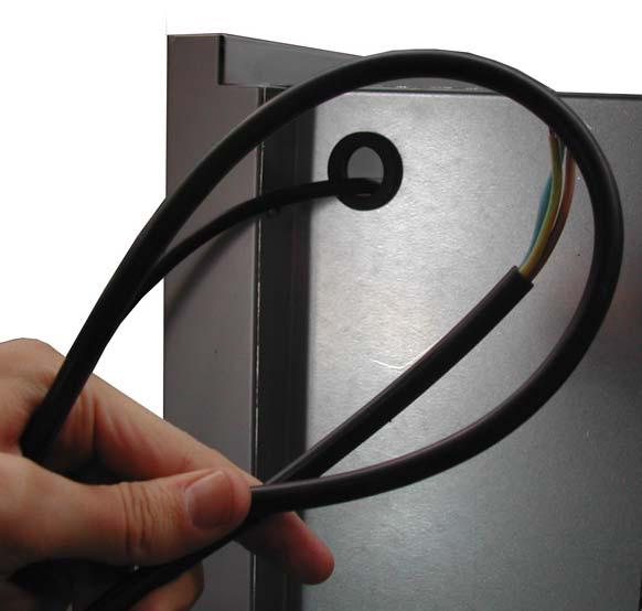
17 Close the control panel with the front piece: Pass through the Ø30 grommet locations in the rear enclosure the rest of the wiring (labelled): 1. Backfire probe, ash collection cable. 2. Rest of the wiring. 3. Network cable. 16


18 1 3 2 Fix the ceiling enclosure (5) inserting the riveted centering tool in the tore locations of the sides: 17


19 Final state: 3. Install the burner with the studs (13) in the location of the rear part of the boiler: 18

20 Over the burner the ceramic or stainless steel piece (2) that is found in the box: 4. Connect the flue duct to the chimney. The diameter of the chimney must be at least equal to the boiler flue duct and will have the necessary draught as specified in the technical specifications. The mounted chimney will allow its cleaning and/or replacement of a section without having to move the boiler from its position. The exhaust gases from the boiler cannot under any circumstances support the weight of the chimney pipe. The chimney pipe shall be attached to other elements, never to the boiler. 5. Then proceed to complete the rest of the hydraulic installation: - Connect the return pipes with tap to the boiler outlet. - Placement of the fill cock connecting it to the lower pipe (water return). A flap valve must be placed to prevent communication between boiler water and water from the supply when the network pressure drops and the filling valve opens. - Installation of air-traps and safety valve. - Installation of water expansion vessel. - Conduct the safety valve and the discharge pipe to the drainage. - Installation of any other component, in addition to those above, that it is necessary to comply with the existing regulations for this type of installations. TANK / AUGER ATTENTION To place the tank and auger selected, read the biomass transports manual, supplied with the boiler. 19
21 OPERATING INSTRUCTIONS ATTENTION To control it appropriately, please consult the electronic regulation manual included with the boiler. REGULATION OF THE POWER OPERATING PARAMETERS VALUES The regulation of the power obtained from the boiler is made with the run time parameters and the stop time of the fuel feed. Changing the values of these parameters will result in different fuel consumption. The power must be selected depending on the demand of the installation, thus, once the temperature reaches the selected level, the burner will automatically shut off until such time that the water in the boiler drops below that level. REGULATION OF THE COMBUSTION AIR The combustion air can be regulated by a fan flap. The required flow will mainly vary depending on the power required, i.e., depending on the amount of fuel that is burning; but the specific characteristics of the fuel used (moisture, density, impurities, ) will also have an influence. As a guide, it can be stated that, with a chimney that provides the right draught, the degree of opening of the flap should be: - For maximum power: between 75% and 90%. - For minimum power: between 10% and 20%. Due to major differences that may exist between different fuels, to obtain an optimum air flow it is necessary to verify the correct combustion in the boiler and the gases temperature in the chimney that cannot exceed the values indicated in this manual. 20
22 IGNITION AND SHUTDOWN Proceed as indicated in the "CONTROL PANEL DIGITAL CONTROL". Before the ignition of the boiler check that the following elements are working properly and are in good condition: Sealing gaskets of the boiler, including front doors, burner plate and connections of the flue duct/chimney. Electronic control and rest of boiler regulation and control elements. Electricity and fuel facilities. Hydraulic installation. Check the operation of the circulator and check that the taps to the output of the boiler are open. Security systems according to the Existing Regulations. Level of water in the boiler. Check that the pressure is of at least 1.5 bar. Then, proceed to the ignition of the boiler: 1. If necessary, clean the combustion chamber, burner and ash collection tray. 2. Fill the fuel tank. 3. Close the doors and allow the fuel in the burner to start to burn (3 5 min.). 4. Once on, switch to automatic mode and the electronic control will start with the operation cycles according to the scheduled times. ATTENTION In the automatic ignition always keep the boiler doors closed to avoid any gas flue or possible deflagration. MAINTENANCE REGULAR INSPECTIONS These inspections may uncover irregularities that could lead to losses in efficiency and/or possible failures in the equipment. Below are examples of operations to be performed during regular inspections: Cleaning of the boiler heat transfer surfaces. Check the values entered into the control programming. Control of burner settings using a combustion analyzer. Check the good condition of the thermal insulation. Verify the absence of: o Fumes (smells), especially toxic. o Leakage of combustible gases (soot deposits/marks). o Noise (excessive or unusual). o Vibration (excessive or unusual). o Water leaks. 21
23 CLEANING OF THE BOILER Cleaning and maintenance of the boiler and its installation are essential for a proper, clean, economical and safe operation. The combustion chamber and fuel gases passages must be cleaned to remove ash deposits that can damage and reduce the rate of energy combustion transmission to the water. A loss of performance may occur due to an increase in the temperature of the exhaust gases from the boiler. A temperature increase in the gas duct of 100ºC is indicative that it is producing a 5% reduction in boiler efficiency. The user should follow the below recommendations for maintenance and cleaning of the boiler: 1.) To empty the ash tray without turning off the boiler, we need to put the controller in manual mode and take out the tray with protective gloves (thermal). Ashes will be temporarily gathered in a non-combustible container until they are completely off. This container will need to be far away from any combustible material. 2.) It is recommended to empty the tray at least once a week, regardless of the fuel used. 3.) The air intake both from the fan and the auger motors will need to be kept clean. To clean them it is necessary to electrically turn off the boiler. Only employ a DRY brush. It is not recommended the use of any chemicals. 4.) To clean the fumes passage, turn 360º the control located in the upper side of the boiler. You will hear a bang. Repeat this operation several times. It is recommended to do the fumes cleaning at least twice a week. 5.) Once finished any cleaning it is necessary to review all elements of the boiler (hoses, lids and doors seals, connections, connections, etc ) before starting the boiler again. 6.) There is no need to grease the augers, only to clean the motors air inlet. 22
24 MODEL REPLACEMENTS AND COMPONENTS BODY OF THE BOILER. Cods Insulation support 23
25 Mark Code Designation Qty. BSELCT-35 BSELCT-50 BSELCT Body of the boiler BIOSELECT-35 (Q.F.) Body of the boiler BIOSELECT-50 (Q.F.) Body of the boiler BIOSELECT-65 (Q.F.) /2" 4 bulbs sheaths Flat spring bulbs sheath Bulbs fixing clip /4" Pressure tap connection /4" MD/MK peephole 1 7A Glass fiber insulation 7B
26 MODEL REPLACEMENTS AND COMPONENTS BOILER ENCLOSURES 25
27 Mark Code Qty. Designation BSELCT-35 BSELCT-50 BSELCT-65 BSELCT-35 BSELCT-50 BSELCT Right side enclosure Left side enclosure Rear sheet enclosure Upper ceiling enclosure Lower enclosure front door Upper enclosure front door M4x7 screw M5x9 screw M-5 nut ST d3,2x6 rivet ST d3,2x16 rivet Riveted centering clip Riveted centering clip Centering cone Grummets 3 26
28 MODEL REPLACEMENTS AND COMPONENTS FUMES AUTOMATIC CLEANING CODE Mark Designation Qty Arm support reaction ,12 Kw Motor-reducer set Reaction arm Motor-reducer axis adaptor Key Automatic cleaning system protection M-8x12 stud M-8x25 screw M-10 nut D8 flat washer D10 flat washer 2 27
29 MODEL REPLACEMENTS AND COMPONENTS ACCESSORIES CODE Mark Designation Qty Manoeuvre handle (cleaning) Cleaning brush /8 x100 sheath(fumes probe Mods. PLUS) 1 28

30 HOT WATER BOILER FOR HEATING MANUFACTURER WARRANTY COD Manufacturer: LASIAN Tecnología del Calor, S.L. This complementary sheet is completed by the installer and user Nº IMPORTANT Read the content of this warranty sheet carefully. Should you have any doubt of interpretation consult your installer, seller or T.A.S. in your area. Fill in all required information on the warranty card and always retain this sheet, as it will be necessary to show it to our T.A.S. so any repair or inspection can be performed under warranty. The completion of the data in the manufacturing warranty card, assumes that the user acknowledges and accepts the terms and conditions of this Warranty Certificate. VALIDITY 1- The warranty comes into force from the date of start-up. This start-up is included in the price of the boiler but not the displacement caused for such start-up. The warranty duration is three years for the boiler body. The first two years include the material and labour and displacement costs and the third year only covers the material. 2- For the other components, it is established a two-year warranty on parts, labour and displacement, as long as a review or maintenance has been made by a T.A.S. or an entity authorized by LASIAN Tecnología del Calor, S.L This period of warranty coverage is valid for domestic use of the product. For any other use, the components will have a one-year warranty coverage, including labour and displacement. 3- To validate the warranty it is essential that a copy of the accompanying warranty card is sent to LASIAN Tecnología del Calor, S.L., and is received by our After Sales Department within 30 days from the installation of the equipment. Just a proof of purchase will not be accepted as a document to validate the warranty. COVERAGE 1- The manufacturer warrants their product exclusively against anomalies caused by manufacturing defects, consisting of repair or replacement, "in situ" or in the service facility, of the defective parts. 2- The warranty does NOT cover:. Parts that require change due to wear and tear, even if it occurs before the end of the warranty s validity term.. FAULTS CAUSED AS A RESULT OF IMPROPER INSTALLATION, NEGLIGENCE IN THE USE OF THE BOILER, LACK OF MAINTENANCE AND CLEANING, HANDLING BY UNQUALIFIED STAFF, IMPROPER OPERATION CONDITIONS, OR DAMAGE CAUSED IN TRANSPORTATION, HANDLING AND STORAGE OF THE BOILERS IN HOUSING OR PROPERTY DURING ITS INSTALLATION.. Breakdown of electrical components or product performance failures that may have occurred by external agents: storms, lightning, power surges or failure in the power supply, lack of earth connection, eddy currents, electromagnetic waves, etc.. Interventions that may be required due to poor water or fuel quality: - Water with high limescale index or chloride concentration greater than 300 mg/l. - Warranty does not cover damage to body boilers that may arise from operation of the burner with an airlock or low-pressure circuit, by filling a circuit while warm, freezing of the water contained in the boiler, calcareous obstructions or dirt, etc. Only will be covered perforations in the form of pores caused by possible defects in the conformation of the material. - Insufficient air inlet grilles for the combustion. - THERMAL GROUPS OR LIQUID FUEL BOILERS - Contaminated heating oil or water concentration greater than 250 mg/kg. - BIOMASS BOILERS OR SOLID FUELS - Fuels with a moisture content above 20%.. - Splinter size bigger than what specified in the G50 type. - Ensure unrestricted water recirculation for boiler as specified in the corresponding manual. - Ensure unrestricted chimney draft or section as specified in the corresponding manual.. THE WARRANTY DOES NOT COVER ANY FAULT THAT MAY ARISE DUE TO IMPROPER INSTALLATION OF THE SAME.. The warranty does not cover the review or maintenance service made one year after the start-up of the boiler. WARRANTY CONDITIONS 1- Warranty will be voided if the start-up of the appliance is not done by the Technical Assistance Service or by a person professionally accredited and authorized by the manufacturer. 2- If during the start-up of the boiler the T.A.S. detects any anomaly or defect in the installation, deficiency in the location (space, room ventilation, gas exhaust, etc..), the T.A.S. will not be forced to perform the start-up until the defect has been corrected and, if deemed appropriate, charge displacement expenses. 3- After the start-up, the T.A.S. (or authorized person or entity if applicable) will sign and stamp the warranty validating it. This "user" warranty sheet will be held by the same and will always be available when intervention in the boiler is required under the warranty concept. 4- Under no circumstances should the complete set of the boiler or burner be changed without the manufacturer authorization. 5- The manufacturer reserves the right to make product changes without notice, always maintaining the technical and essential service characteristics to fulfil the purpose for which the boiler is intended. 6- The manufacturer assumes no responsibility for damages caused to persons or property arising from accidents that are not exclusively from the boiler itself as an individual unit and for manufacturing defects. 7- In case of dispute, the customer waives their own jurisdiction and agrees to submit to the courts of Zaragoza or the designated by the manufacturer. USEFUL TIPS Do not handle the inside of the boiler. If you are unsure of its correct performance, please read carefully the instruction manual included with each appliance or consult your local Technical Service. To maintain optimal operation of the boiler or heating unit LASIAN, we recommend an annual review of the same by a member of our T.A.S. or an entity authorized by LASIAN Tecnología del Calor S.L., which for convenience we recommend you to perform it at the end of the heating season. LASIAN Tecnología del Calor S.L. 29
 - SPAIN Manufacturer of boilers for heating and S.H.W.")
31 DECLARATION OF CONFORMITY In compliance with the requirements of the COUNCIL OF THE EUROPEAN UNION The Company LASIAN Tecnología del Calor, S.L. with C.I.F. B , and registered address at: Políg. Ind. Las Norias, parcela nº MUEL (Zaragoza) - SPAIN Manufacturer of boilers for heating and S.H.W., brand: LASIAN In its different models: BIOSELECT / BIOSELECT PLUS 35 BIOSELECT / BIOSELECT PLUS 50 BIOSELECT / BIOSELECT PLUS 65 WE HEREBY DECLARE, under our sole responsibility, that the above mentioned products are manufactured in accordance with the following directives: Machinery Directive (98/37/CE) Low Voltage Directive (2006/95/CE) Electromagnetic Compatibility Directive (89/336/CEE) Regulations on Thermal Installations in Buildings (RITE), Adopted by Royal Decree 1027/2007. Complying in all cases with all the specifications of these, applying in all the models the provisions of the heating boilers standard: UNE EN Heating boilers. Part 5. Heating boilers for solid fuels, manually and automatically stoked, nominal heat output of up to 500 kw. Muel, 8 th November 2013 The characteristics and manufacture date on each unit are indicated in the technical documentation that accompanies each boiler. 30

32 NOTES The manufacturer assumes no responsibility for damages caused to persons or property from accidents that are not exclusively from the boiler itself as an individual unit NOTE: The manufacturer reserves the right to make product changes without notice, always maintaining the essential characteristics to fulfil the purpose for which the boiler is intended. Technical Service: 31
INSTALLATION AND OPERATING INSTRUCTIONS BIOCLASS HM
 INSTALLATION AND OPERATING INSTRUCTIONS BIOCLASS HM Thank you for choosing a DOMUSA TEKNIK heating boiler. Within the product range offered by DOMUSA TEKNIK you have chosen BioClass HM model. With a suitable
INSTALLATION AND OPERATING INSTRUCTIONS BIOCLASS HM OD (FOR EXTERNAL USE)
") INSTALLATION AND OPERATING INSTRUCTIONS BIOCLASS HM OD (FOR EXTERNAL USE) Thank you for choosing a DOMUSA TEKNIK heating boiler. Within the product range offered by DOMUSA TEKNIK you have chosen BioClass
INSTALLATION AND OPERATING INSTRUCTIONS BIOCLASS HM OD (FOR EXTERNAL USE) Thank you for choosing a DOMUSA TEKNIK heating boiler. Within the product range offered by DOMUSA TEKNIK you have chosen BioClass
LISEO Insert. European Standard Certification UNE EN inserts. LISEO s.r.o. Folknářská 1246/21 Děčín 2 Nové Město
 LISEO Insert European Standard Certification UNE EN-13229 inserts LISEO s.r.o. Folknářská 1246/21 Děčín 2 Nové Město 405 02 INTRODUCTION.4 1. GUARANTEE CONDITIONS.4 1.1. SAFETY WARNINGS....4 1.2. GUARANTEE
Pellet Boilers. Instructions for Use and Maintenance
 Pellet Boilers Instructions for Use and Maintenance - THE PRESENT MANUAL FORMS AN INTEGRAL PART OF THE BOILER AND MUST BE KEPT FOR FUTURE REFERENCE Bmax Technology - a Division of Elmec Group S.r.l. Localition
LISEO STOVES. European Standard Certification UNE EN stoves. LISEO s.r.o. Folknářská 1246/21 Děčín 2 Nové Město
 LISEO STOVES European Standard Certification UNE EN-13240 stoves LISEO s.r.o. Folknářská 1246/21 Děčín 2 Nové Město 405 02 INTRODUCTION.3 2 1. GUARANTEE CONDITIONS.3 1.1. SAFETY WARNINGS..3 1.2. GUARANTEE
HEAT RECOVERY AIR HANDLING UNIT
 HEAT RECOVERY AIR HANDLING UNIT OPERATION MANUAL KOMFORT_L v2(2)_en.indd 1 07.08.2015 15:0:44 CONTENTS Introduction General Safety regulations Transportation and storage regulations Manufacturer's warranty
INSTALLATION, OPERATION AND MAINTENANCE. Ariterm Hybrid 20
 INSTALLATION, OPERATION AND MAINTENANCE Ariterm Hybrid 20 TABLE OF CONTENTS General...3 Installation... 4-5 Dimensions - with flue gas exhauster...6 Dimensions - without flue gas exhauster...7 Pipe installations...8
WHE 2.24 / WHE 2.24 FF
 EN Wall-hung gas boilers WHE 2.24 WHE 2.24 FF User Guide 300011777-001-C . Contents 1 Introduction.............................................................................3 1.1 Symbols used...........................................................................................3
USERS MANUAL FOR GAS BOILERS
 USERS MANUAL FOR GAS BOILERS PLEASE READ THE MANUAL CAREFULLY: IT CONTAINS IMPORTANT INFORMATION REGARDING SAFETY, INSTALLATION, USE AND MAINTENANCE OF THE APPLIANCE MODELS: NOVADENS 24 NOVADENS 24C NOVADENS
USER MANUAL 9kW LILLY PELLET STOVE
 USER MANUAL 9kW LILLY PELLET STOVE Table of Contents.Overview of Stove Parts... 2.Technical Characteristics... 3 3.Important Information... 4 4.Pellet Specification...5 5.Technology... 6 6.Installation...
Trumatic E. Trumatic E 2400 (Australia) Operating instructions Page 4 Installation instructions Page 7. To be kept in the vehicle!
 Operating instructions Page 4 Installation instructions Page 7. To be kept in the vehicle!") Trumatic E 7 7 2 9 9 4 Trumatic E 2400 (Australia) Operating instructions Page 4 Installation instructions Page 7 To be kept in the vehicle! Trumatic E 2400 (Australia) Table of contents Installation example...
Trumatic E 7 7 2 9 9 4 Trumatic E 2400 (Australia) Operating instructions Page 4 Installation instructions Page 7 To be kept in the vehicle! Trumatic E 2400 (Australia) Table of contents Installation example...
AXIS-QA G TUBO-M/MZ AXIAL FANS. Axis / Tubo OPERATION MANUAL
 TUBO-M/MZ AXIS-QA AXIS-Q TUBO-F AXIS-QR AXIS-F AXIS-QRA AXIS-QA G AXIAL FANS EN OPERATION MANUAL www.blaubergventilatoren.de CONTENT 3 Introduction 3 General 3 Safety rules 3 Transport and storage requirements
INLINE CENTRIFUGAL FAN. Centro-M OPERATION MANUAL
 INLINE CENTRIFUGAL FAN OPERATION MANUAL www.blaubergventilatoren.de CONTENT 3 Introduction 3 General 3 Safety rules 3 Transport and storage requirements 3 Manufacturer's warranty 4 Fan design 4 Delivery
DH-Direct Fired Poultry Farm Diesel Heater
 DH-Direct Fired Poultry Farm Diesel Heater Comparison of Diesel Heater to Gas Heater Diesel LPG Gas LPG Gas KW 43 70 120 Fuel consumption/hr 3 5.1 8.8 Heat output 37000 60000 100000 Cost of fuel/lit or
INLINE СENTRIFUGAL FAN BOX BOX-R OPERATION MANUAL
 INLINE СENTRIFUGAL FAN BOX BOX-R OPERATION MANUAL CONTENT 3 Introduction 3 General 3 Safety rules 3 Storage and transportation rules 3 Manufacturer s warranty 4 Fan design 4 Delivery set 5 Technical data
Corn Flame Energy Corn Stove Model 3000
 Corn Flame Energy Corn Stove Model 3000 Installation and Operation Guide Read thoroughly before starting installation Save this manual for future reference SAFETY NOTICE If this stove is not properly installed,
INSTALLATION AND OPERATING INSTRUCTIONS GN2. HIGH EFFICIENCY CAST IRON BOILER FOR LIQUID and/or GAS FUELS
 INSTALLATION AND OPERATING INSTRUCTIONS HIGH EFFICIENCY CAST IRON BOILER FOR LIQUID and/or GAS FUELS INDEX 1. Technical information... page 3 2. Dimensional and technical characteristics... page 3 3. Packing
Installation & Manual. Model T-25
 Installation & Manual TR Central Heating Stove With Solid Fuel Model T-25 Tested according to DIN EN 13240 For product efficiency and emission values, see the declaration of conformity! TABLE OF CONTENTS
Installation Instructions T 9822 Gas Dryer. en - US, CA. To prevent accidents
 Installation Instructions T 9822 Gas Dryer To prevent accidents en - US, CA and appliance damage read these instructions before installation or use. M.-Nr. 07 431 110 2 WARNING For your safety the information
HG 675 CX 60 HG 675 CN 60 HG 675 CW 60
 HG 675 X 60 HG 675 CX 60 HG 675 CN 60 HG 675 CW 60 1 2 1. : 93/68: 90/396: 2006/95/CE: 2004/108/CE: - 1935/2004:. 2002/95/CE: RoHS 2.,.,,,,...,. (,..)..,,.,. ( ),,, ;,,.,.....,.,,,,,,...,. (..),,.,..,.,,,,
Page 1. Cube Ref:
 Page 1 Cube Ref: 388117 Linedrawing: Technical characteristics: Unit dimensions (cm) Fire box dimensions (cm) Flue Diameter Flue outlet Recommended fuel Log size loading from the front: Panoramic glass
High Performance Electronic Modulation Automatic Cleaning Easy Installation 4 Power Levels: 9,15,25,42kW. Pellet Boilers. Future of Ecological Heating
 Pellet Boilers High Performance Electronic Modulation Automatic Cleaning Easy Installation 4 Power Levels: 9,15,25,42kW Future of Ecological Heating Why choose an Ekoheat boiler? Ekopower is an innovative
So old fashioned... As the combustion chamber is completely room sealed, it does not release any smells and does not dirty.
 ARREDO E BENESSERE So old fashioned... An intelligent choice When on a cold winters night the warm glowing flames of the KALDUS boiler are there to welcome you back home, you will be pleased that you decided
IDE 20 / IDE 30 / IDE 50 IDE 60 / IDE 80
 IDE 20 / IDE 30 / IDE 50 IDE 60 / IDE 80 EN OPERATING MANUAL OIL HEATER TRT-BA-IDE20-30-50-60-80-TC-001-EN Table of contents Information on the use of this manual... 1 Scope of delivery... 1 General safety...
Cooker Hood LA-72-CAN.
 Cooker Hood LA-72-CAN EN www.luxairhoods.com WARNINGS Safety This equipment can be used by children aged 8 or more, people with physical, mental and sensory disabilities or inexperienced users it they
OPERATING INSTRUCTIONS with safety features
 Solid fuel boiler TKK3 with wood pellet burner TERMEC 70-90 KW OPERATING INSTRUCTIONS with safety features Prhova ka bb 22310 imanovci, Srbija Tel/Fax. +381 22 480404 +381 63 259422 oce@termomont.rs www.termomont.rs
SOUND-INSULATED FAN. Iso-K OPERATION MANUAL. Iso-K_v.1(2)-EN.indd :20:59
-EN.indd :20:59") SOUND-INSULATED FAN OPERATION MANUAL _v.1(2)-en.indd 1 10.08.2015 15:20:59 CONTENT Introduction 3 General 3 Safety rules 3 Transport and storage requirements 3 Manufacturer's warranty 3 Fan design 4 Delivery
SOUND-INSULATED FAN OPERATION MANUAL _v.1(2)-en.indd 1 10.08.2015 15:20:59 CONTENT Introduction 3 General 3 Safety rules 3 Transport and storage requirements 3 Manufacturer's warranty 3 Fan design 4 Delivery
INSTRUCTIONS FOR INSTALLATION AND MANUAL Solid fuel stove for central heating THERMO IN
 INSTRUCTIONS FOR INSTALLATION AND MANUAL Solid fuel stove for central heating THERMO IN To respected customer, We are very pleased for your trust and your decision to buy our product. You made a good choice,
AZN ATEX INSTALLATION AND MAINTENANCE
 ZerAx AZN ATEX INSTALLATION AND MAINTENANCE 924714-0 English 924714-0 GB ZerAx axial flow fans type AZN ATEX Installation and maintenance 1. Application 2. Handling 2.1 Marking 2.2 Weight 2.3 Temperature
TECHNICAL AND OPERATIONAL DOCUMENTATION
 METAL AND BOILER FACTORY 28-100 Busko-Zdrój, Owczary, ul Przemysłowa 3 Tel No +4841 378 46 19, fax +4841 370 83 10 TECHNICAL AND OPERATIONAL DOCUMENTATION SAS MULTI FLAME BURNER ADAPTED FOR BURNING OF
1 VICTRIX ZEUS Superior kw I features
 Wall-hung condensing VICTRIX ZEUS Superior kw I is the new range of wall-hung condensing boilers with 54 litre stainless steel storage tank available in two versions with nominal heat output of 26 kw and
Easyfire Standalone biomass pellet boiler
 Easyfire Standalone biomass pellet boiler DESIGN Essential and pleasant AESTETIC, small size If the humanity is in balance with the resources of nature, the respect for the environment will be possible.
USER S INFORMATION MANUAL
 USER S INFORMATION MANUAL UPFLOW & DOWNFLOW/HORIZONTAL CONDENSING GAS FURNACES SAFETY Recognize this symbol as an indication of Important Safety Information If not installed, operated and maintained in
CentroPelet ZV14 TECHNICAL INSTRUCTIONS HEATING TECHNIQUE. for regulation, use and maintenance of pellet stove
 HEATING TECHNIQUE Centrometal d.o.o. - Glavna 12, 40306 Macinec, Croatia, tel: +385 40 372 600, fax: +385 40 372 611 TECHNICAL INSTRUCTIONS for regulation, use and maintenance of pellet stove CentroPelet
2.1 BOILER ROOM BOILER ROOM DIMENSIONS 2.3 CONNECTING UP SYSTEM 2.4 CONNECTING UP FLUE 2.5 ELECTRICAL CONNECTION
 FONDERIE SIME S.p.A. of Via Garbo 27 - Legnago (VR) - Italy declares that its diesel-burning boilers are produced in accordance with the requirements of article 3 paragraph 3 of Directive PED 97/23/EEC
WHU WATER HEATING UNITS. GENERAL MANUAL MODEL KEY. June 2007 WHU WATER HEATING UNITS
 WHU WATER HEATING UNITS GENERAL MANUAL MODEL KEY WHU Water Heating Unit Maximum heating power, kw Max. water inflow pressure, bar Voltage options GENERAL INFORMATION WHU water heater, producing hot water
Section 1 - Safety Information Section 2 - Installation: Wall Mount Hoods Section 3 - Installation: Island Mount Hoods
 Range Hoods Owner s Manual Section 1 - Safety Information Section 2 - Installation: Wall Mount Hoods Section 3 - Installation: Island Mount Hoods Section 4 - Use & Care Instructions Section 5 - Control
DTG Eco / V130
 ECODENS Gas fired condensing boiler EN User Guide 300010111-001-B Contents 1 Introduction.............................................................................3 1.1 Symbols and abbreviations................................................................................3
INSTRUCTIONS FOR INSTALLATION, SETTING AND USE
 BUILT-IN FIREPLACE INSTRUCTIONS FOR INSTALLATION, SETTING AND USE 1. BUILT-IN FIREPLACE SPECIFICATION - WIDE 730 mm - DEPTH 426 mm - HEIGHT 543 mm - NOMINAL POWER 11 KW - CHIMNEY POT DIAMETER Ø 180 mm
Installation Manual. Instrucciones de instalación y manual de usuario 1
 Installation Manual Instrucciones de instalación y manual de usuario 1 Installation instructions and user manual V8 2 INDEX 1 GENERAL SAFETY WARNINGS... 4 2 OPERATING PRINCIPLE... 5 3 TECHNICAL FEATURES...
USER S INFORMATION MANUAL
 USER S INFORMATION MANUAL HOT WATER HEATING BOILERS DOMESTIC WATER HEATERS 150,000-300,000 Btu/hr MODELS EB-EWU-02 IMPORTANT INSTALLER - AFFIX INSTALLATION MANUAL ADJACENT TO THE BOILER CONSUMER - RETAIN
BIX B-One 100 kw INSTALLATION GUIDE
 BIX B-One 100 kw INSTALLATION GUIDE Dear Customer, We thank you for choosing our product. The Bix B-One 100 Kw is a burner of advanced concept and technology, with a high reliability and construction quality.
USER S MANUAL. Heat Recovery Ventilator. Vents Brig HRV 200 Vents Brig HRV 300
 USER S MANUAL Heat Recovery Ventilator Vents Brig HRV 200 Vents Brig HRV 300 2 Brig HRV 200 (300) CONTENT Introduction... 3 Application... 3 Delivery set... 3 Unit designation key... 4 Basic unit dimensions...
PELLETS BURNER 15-60kW MOC
 PELLETS BURNER 15-60kW MOC. Please read those documentation before first start up the unit. Improper burner start may lead to its damage and may create a danger for end user! Table of Contents: 1. Admission
Light oil / kerosene burner
 Installation, use and maintenance instructions Light oil / kerosene burner One stage operation CODE MODEL TYPE 374445 G5 444T50 290238 (5) - 05/20 TECHNICAL DATA Thermal power output 28 60 kw 2.3 5 kg/h
1. The structure and its description
 Thank you for using our KYUNG-DONG NAVIEN. To use this boiler in the proper way, be sure to read this manual fully before using it, and keep this manual with the warranty of the quality in a safe place.
Forced draught gas burner
 Installation, use and maintenance instructions Forced draught gas burner Code Model Type 3751982 GAS 3 519T80 291 (3) - 02/2010 DECLARATION Declaration of conformity in accordance with ISO / IEC 17050-1
Remeha. Fuel oil/gas boilers P 520. Installation and Service Manual A
 Remeha Fuel oil/gas boilers EN Installation and Service Manual 300016859-001-A 63115 Declaration of conformity The appliance complies with the standard model described in declaration of compliance. It
JUMBO INDIRECT FIRED DIESEL HEATER OPERATING INSTRUCTIONS
 JUMBO INDIRECT FIRED DIESEL HEATER OPERATING INSTRUCTIONS Before using the heater, read and understand all instructions and follow them carefully. The manufacturer is not responsible for damages to goods
CINCINNATI, OH USA
 INSTRUCTION MANUAL Part No. 89731 Revised October 1997 CINCINNATI, OH 45241-4807 USA GAS SAFETY PRECAUTIONS Instructions on what to do when a user smells gas can be obtained from the local gas supplier.
E-COMBI EVO E-SYSTEM EVO
 E-COMBI EVO E-SYSTEM EVO User s manual CONDENSING WALL-HUNG GAS BOILER G.C.N.:47-116-68 (24 kw) G.C.N.:47-116-69 (30 kw) G.C.N.:47-116-70 (38 kw) G.C.N.:41-116-39 (24 kw) G.C.N.:41-116-40 (30 kw) Country
KKKKKKKCOOKER HOOD INSTRUCTION MANUAL
 KKKKKKKCOOKER HOOD INSTRUCTION MANUAL Read this manual carefully before operation Pictures in this manual are for reference only, the product in kind prevail. E60MEW2M19 Contents 01 02 03 04 05 06 07 08
TECHNICAL MANUAL BIOTEC 25 AND BIOTEC 40
 TECHNICAL MANUAL BIOTEC 25 AND BIOTEC 40 2 INDEX INDEX Safety information.......4 Technical data...5 Boiler features...6 Technical information........7 Fuel...... 8 Construction and function...... 9 Hydraulic
VICTRIX 90 VICTRIX 115 Wall-hung condensing boilers for high power
 VICTRIX 90 VICTRIX 115 Wall-hung condensing boilers for high power VICTRIX 90 is the new wall-hung condensing boiler for room heating only, set-up for independent functioning and for that in cascade mode
Installation, operation and care. Pellmax UB. Burner not included Replaces:
 Installation, operation and care Burner not included 2011-11-11 ver: Replaces: Contents 11.11 otes...3 General...4 Function...4 Technical data...5 System principle Pellmax with radiator and tank-in-tank
COMBY 4000 & 9000 STEAM CLEANER OPERATOR MANUAL
 COMBY 4000 & 9000 STEAM CLEANER OPERATOR MANUAL Clemas & Co. Unit 5 Ashchurch Business Centre, Alexandra Way, Tewkesbury, Gloucestershire, GL20 8NB. Tel: 01684 850777 Fax: 01684 850707 Email: info@clemas.co.uk
Problem Cause Remedial action. Gauge glass There was excess chemical dosage The normal ph recommended was 9.5 to See photo 3 & 4.
 CASE STUDIES OF STEAM SYSTEM AUDIT IN SOME PLANTS By K.K.Parthiban, Venus Energy Audit System Introduction This article outlines the outcome of auditing of steam system conducted in process Industries.
INSTALLATION AND OPERATING INSTRUCTIONS. Ariterm 60+
 INSTALLATION AND OPERATING INSTRUCTIONS Ariterm 60+ CONTENTS General.... 2 Installation.... 4-5 Installation of temperature limit valve... 6 Measurements and connections... 7 Technical specifications and
Solid fuel hot water boiler TKH KW INSTRUCTIONS MANUAL for usage and maintenance
 Solid fuel hot water boiler TKH 250-400 KW INSTRUCTIONS MANUAL for usage and maintenance Prhovacka bb 22310 Simanovci, Srbija Tel/Fax. +381 22 480404 +381 63 259422 oce@termomont.rs www.termomont.rs April
Operating instructions
 Operating instructions Gas condensing boiler WARNING: If the information in this manual is not followed exactly, a fire or explosion may result causing property damage, personal injury or loss of life.
Cookshack, Inc. Model FEC100 Fast Eddy Oven. Version /1/10
 Cookshack, Inc. Model FEC100 Fast Eddy Oven Operator s Manual Please read this entire manual installation and use of this pellet fired smoker oven. Failure to follow these instructions could result in
PELLET BURNER PV 350
 PELLET BURNER PV 350 INSTRUCTION MANUAL v1.1 1 PRODUCT DESCRIPTION...3 2 SAFETY RULES...3 3 WARNINGS...4 4 INSTALLATION INSTRUCTIONS...5 4.1 BOILER REQUIREMENTS...5 4.2 PELLET CONTAINER...6 4.3 INSTALLATION
STORAGE WATER HEATERS
 Owners Manual STORAG WATR HATRS RBC 200, RBC 300, RBC 400, RBC 500, RBC 500HP, RBC 750, RBC 1000, RBC 1000HP, RBC 1500, RBC 2000, RBC 3000 N v. 1.4 CONTNTS 1 Description... 3 1.1 Models... 3 1.2 Tank protection...
Importance of a Draught Regulator
 Importance of a Draught Regulator The purpose of a chimney (stack) is to generate a draught (draft) that will transport smoke and fumes away from the point of combustion. The chimney design and arrangement
USER S MANUAL. Centrifugal inline fan. VKMz 100 Q VKMz 100 VKMz 125 Q VKMz 125. VKMz 250 Q VKMz 250 VKMz 315 Q VKMz 315
 USER S MANUAL VKMz 100 Q VKMz 100 VKMz 125 Q VKMz 125 VKMz 150 VKMz 160 VKMz 200 Q VKMz 200 VKMz 250 Q VKMz 250 VKMz 315 Q VKMz 315 Centrifugal inline fan VKMz CONTENTS Contents... 2 Safety requirements...
Installation instructions for the T 9820 Gas Dryer
 Installation instructions for the T 9820 Gas Dryer The T 9820 gas dryer is only approved for use in the USA and Canada. It is not approved for use in Mexico. To prevent accidents en - US, CA and machine
INSTALLATION AND OPERATION GUIDE FOR HARGROVE GAS LOGS
 NOTE! INSTALLATION AND OPERATION GUIDE FOR HARGROVE GAS LOGS SEE THRU FIREPLACES NATURAL GAS ADEQUATE FIREPLACE VENTILATION IS REQUIRED FOR SAFETY. GAS LOGS MUST BE INSTALLED BY PERSONNEL QUALIFIED FOR
FIREPLACE SIZES FOR YOUR SAFETY DO NOT STORE OR USE GASOLINE OR OTHER FLAMMABLE VAPORS AND LIQUIDS IN THE VACINITY OF THIS OR ANY OTHER APPLIANCE.
 RGA 2-72 INSTALLATION AND OPERATION GUIDE FOR HARGROVE GAS LOGS PROPANE GAS ADEQUATE FIREPLACE VENTILATION IS REQUIRED FOR SAFETY. GAS LOGS MUST BE INSTALLED BY PERSONNEL QUALIFIED FOR INSTALLING GAS APPLIANCES.
HEAT RECOVERY VENTILATOR
 HEAT RECOVERY VENTILATOR HRV H 00 ERV H 00 HRV H 300 ERV H 300 EN OPERATION MANUAL HRV /ERV H 00(300) www.blaubergventilatoren.de CONTENTS Application... Delivery set...3 Unit designation key...3 Basic
Eco Angus Wood Pellet Boilers
 Eco Angus Wood Pellet Boilers ISO 9001 ISO 14001 1 Contents 3 Our product philosophy 3 Our approach 3 Manufacturing credentials 4 Orligno 400 4 Boiler construction 5 Boiler description 5 Burner 6 Technical
GFT-060/40/H2. Designed and built According AD-2000 regulation Homologation and branded CE According to the European Directive CE
 Item 1) TWO THERMAL OIL HEATERS OF 1200 kw EACH 1.1) THERMAL OIL HEATER BODY Brand PIROBLOC Model GFT-060/40/H2 Power 1200 kw Delta Temperature 40 ºC Execution Horizontal Designed and built According AD-2000
WALL MOUNT RANGE HOOD. This manual is made with 100 % recycled paper. Electronic version of this manual is available at:
 WALL MOUNT RANGE HOOD This manual is made with 100 % recycled paper. Electronic version of this manual is available at: www.cosmoappliances.com Thank You Thank you for your purchase. We know that you have
User Manual. 110 Cup (55 Cup Raw) Gas Rice Cooker. Model: 177GRCLP, 177GRCNAT 12/2018. Please read and keep these instructions. Indoor use only.
 Gas Rice Cooker. Model: 177GRCLP, 177GRCNAT 12/2018. Please read and keep these instructions. Indoor use only.") 110 Cup (55 Cup Raw) Gas Rice Cooker Intertek 5010781 Conforms to ANSI STD Z83.11-2016 Model: 177GRCLP, 177GRCNAT 12/2018 FOR YOUR SAFETY Do not store or use gasoline or other flammable vapors or liquids
110 Cup (55 Cup Raw) Gas Rice Cooker Intertek 5010781 Conforms to ANSI STD Z83.11-2016 Model: 177GRCLP, 177GRCNAT 12/2018 FOR YOUR SAFETY Do not store or use gasoline or other flammable vapors or liquids
BIOPLEX MCL-BIO INSTALLATION AND SERVICE MANUAL
 BIOMASS-SOLID FUEL RETORT BOILER BIOPLEX MCL-BIO INSTALLATION AND SERVICE MANUAL VERSION: 2.1 UPDATE: 10.10.2013 Contents 1. GENERAL INFORMATION... 3 1.1. Proper use of the appliance... 3 1.2. Safety warnings...
BIOMASS BOILER ATTACK PELLET 30 AUTOMATIC PLUS
 BIOMASS BOILER ATTACK PELLET 30 AUTOMATIC PLUS W W W. A T T A C K. S K MODEL STRUC TURE OF THE AT TACK BOILERS THE NEW LINE OF ATTACK BOILERS FOR WOOD AND PELLETS 3000 000 6000 4 ATTACK FD PELLET yattack
HOT WASHER MODEL NO: KING150
 WARNING: Do not use the hot washer without reading this manual HOT WASHER MODEL NO: KING150 PART NO: 7320175 OPERATION & MAINTENANCE INSTRUCTIONS LS1215 INTRODUCTION Thank you for purchasing this CLARKE
Kyung Dong Oil Boiler. Contents. 1. General Warnings Safety Warnings
 Contents 1. General Warnings --------------------- 1 2. Safety Warnings ----------------------- 2 3. Parts and structure --------------------- 7 4. Safety Device ------------------------- 9 5. Checkups
Boiler Technical Specifications (2013)
") ACT Bioenergy Boiler Dimensions 0.5-0.85 Million Btu/h (150-250kW) Model CP500 CP600 CP750 CP850 Heat Output in MBtu/h (kw) 510 (150) 610 (180) 750 (220) 850 (250) Height ft (mm) 6 1 (1855) 6 1 (1855)
ACT Bioenergy Boiler Dimensions 0.5-0.85 Million Btu/h (150-250kW) Model CP500 CP600 CP750 CP850 Heat Output in MBtu/h (kw) 510 (150) 610 (180) 750 (220) 850 (250) Height ft (mm) 6 1 (1855) 6 1 (1855)
Model RGAC/SGAC Self Contained Cooling/Gas Heat MODELS RGAC & SGAC - R22 USER'S INFORMATION, MAINTENANCE AND SERVICE MANUAL
 Model RGAC/SGAC Self Contained Cooling/Gas Heat Supersedes: 145.24-O1 (708) Units Form 145.24-O1 (908) MODELS RGAC & SGAC - R22 USER'S INFORMATION, MAINTENANCE AND SERVICE MANUAL CATEGORY III GAS HEATING/ELECTRIC
PER-EKO type KSW & KSW PLUS Instruction Manual
 TABLE OF CONTENTS INTRODUCTION..... 3 1. GENERAL INFORMATION..... 3 1.1. Application.. 3 1.2. Fuel..... 3 1.3. Dimensions & technical parameters........ 4 2. BOILER TECHNICAL SPECIFICATION...... 4 2.1.
DIGITAL MODULATING BOILERS
 DIGITAL MODULATING BOILERS FOR HEATING AND SANITARY HOT WATER CMX15 CMX18 CM15 CM18 INSTALLATI INSTRUCTIS AND USER GUIDE Please read these instructions before installing or using this appliance for the
USER MANUAL. 60cm, 3 burners, Hob AKC 630
 USER MANUAL 60cm, 3 burners, Hob AKC 630 For your safety These instructions have been drawn up for your safety and that of others. You are therefore requested to read them carefully before installing
Instruction manual. Remote control electric IR HEATER
 Instruction manual Remote control electric IR HEATER battery consumption rate hour temperature (preset or measured) current operation mode (e.g. comfort) current day heating activated buttons for adjustment
Pellet boiler Electronic Modulation Automatic Cleaning Grinder system Easy Installation 4 power levels: 10, 16, 25, 43 kw
 Pellet boiler Electronic Modulation Automatic Cleaning Grinder system Easy Installation 4 power levels: 0, 6, 5, 4 kw CLASS IN EN 0/5 Innovation with meaning BioClass NG IN EN 0/5 CLASS DOMUSA has managed
ClearFire. Startup Guide. Model CFH. Horizontal Steam Boiler
 ClearFire Model CFH Horizontal Steam Boiler Startup Guide 750-293 www.cleaverbrooks.com Improper installation, adjustment, service, or maintenance can cause equipment damage, personal injury, or death.
Light oil - kerosene burner
 Installation, use and maintenance instructions Light oil - kerosene burner One stage operation CODE MODEL TYPE 374374 G3B 437T 90 (4) - 05/0 TECHNICAL FEATURES TYPE 437T Thermal power output 9 35 kw.6
Owner s Manual. A flame to light up your palate! Table of Contents. Warranty card inside
 Owner s Manual A flame to light up your palate! Table of Contents Safety guidelines............. Description of appliance....... 3 Hardware supplied............ 3 Assembly................... Operation...................
Operating Manual PELLEMATIC PES CMP06 TO_VA6.39 Pelletronic TOUCH ENGLISH. PE 1491 EN_TO 1.0 Europe s specialist in pellet heating
 Operating Manual PELLEMATIC PES 12 56 CMP06 TO_VA6.39 Pelletronic TOUCH ENGLISH PE 1491 EN_TO 1.0 Europe s specialist in pellet heating Title: Operating manual PES 12-56 Article number: PE 1491 EN_TO 1.0
Operating Instructions
 Operating Instructions TEKA Cartmaster Type PF-W 1, PF-W 2 TEKA Absaug- und Entsorgungstechnologie GmbH Industriestraße 13 D-46342 Velen Postfach 1137 D-46334 Velen Tel.: +49 (0) 2863 9282-0 Fax: +49 (0)
B.C.S. Shop Heaters 26, 30 & 36 (36 shown)
") BIOMASS COMBUSTION SYSTEMS, INC. 67 MILLBROOK ST., SUITE 502 WORCESTER, MA 01606 508-798-5970 - FAX 508-798-5971 B.C.S. Shop Heaters 26, 30 & 36 (36 shown) INSTALLATION MANUAL HAND FIRED SYSTEMS 8-09 Biomass
BIOMASS COMBUSTION SYSTEMS, INC. 67 MILLBROOK ST., SUITE 502 WORCESTER, MA 01606 508-798-5970 - FAX 508-798-5971 B.C.S. Shop Heaters 26, 30 & 36 (36 shown) INSTALLATION MANUAL HAND FIRED SYSTEMS 8-09 Biomass
INSTRUCTIONS MANUAL FOR USE AND MAINTENANCE
 INSTRUCTIONS MANUAL FOR USE AND MAINTENANCE Carbel models: C-60 Plus C-70 Plus C-80 Plus C-100 Plus C-70 Plus Double-sided C-80 Plus Double-sided C-100 Plus Double-sided CARBEL C/ Ciudad de Cartagena,
Light oil burners. One stage operation
 Installation, use and maintenance instructions Light oil burners One stage operation CODE MODEL TYPE 3505 RDB CF 38 50 T3 350050 RDBR CF 6 50 TR 35050 RDBR CF 33 50 TR 35050 RDBR CF 38 50 T3R 350650 RDBR
CENTRIFUGAL FANS user's manual. model VENTS VK.
 EN CENTRIFUGAL FANS user's manual model VENTS VK www.ventilation-system.com 2013 EN! WARNING! Disconnect the fan from power mains prior to any connection, servicing and repair operations. Mounting and
Fully-automatic Gas tankless Water Heater USER'S MANUAL FOR MODEL EZ-101 ISO9001 certified
 Fully-automatic Gas tankless Water Heater USER'S MANUAL FOR MODEL EZ-101 ISO9001 certified Thank you for purchasing our fully-automatic gas-fired tankless water heater. Please completely read this Manual
USER S MANUAL NKP. Duct heater for supply air pre-heating with external control
 USER S MANUAL Duct heater for supply air pre-heating with external control CONTENTS Contents... 2 Safety requirements... 2 Purpose... 4 Delivery set... 4 Designation key... 4 Technical data... 5 Design
PLAN THE INSTALLATION Planning the installation first requires selecting the most appropriate installation approach. The chart below offers suggestion
 AUTOMATIC MAKE-UP AIR DAMPER WITH To register this product visit: www.broan.com MODELS MD6T MD8T MD10T READ AND SAVE THESE INSTRUCTIONS FOR RESIDENTIAL USE ONLY Page 1 WARNING TO REDUCE THE RISK OF FIRE,
CARE & INSTRUCTION MANUAL
 CARE & INSTRUCTION MANUAL BLACK CRYSTAL WALL MOUNTED HOOD 5FCB 36 BL Note: To avoid accident and damage, please read these instructions carefully before operating the appliance. Thank You for Choosing
PEGASUS F2 N 2S. CAST IRON GAS BOILER for heating with electronic ignition and flame control INSTRUCTIONS FOR USE, INSTALLATION AND MAINTENANCE
 PEGASUS F2 N 2S CAST IRON GAS BOILER for heating with electronic ignition and flame control INSTRUCTIONS FOR USE, INSTALLATION AND MAINTENANCE cod. 3544309/0 ediz. 01/2003 Carefully read the warnings in
Use and maintenance Manual Longitudinal profile welding Model: LRW-130
 LRW-130 1300 mm. IMPORTANT: Read this user manual and follow the instructions and warnings before operating this device. Any modification or transformation performed on this machine may cause loss of the
USER MANUAL. 80 cm 2 burners, glass hob AKC 820C/BLM
 USER MANUAL 80 cm 2 burners, glass hob AKC 820C/BLM For your safety These instructions have been drawn up for your safety and that of others. You are therefore requested to read them carefully before installing