We want you to save time and money! We assure you that the thorough reading of this manual will guarantee proper installation and safe use of the
|
|
|
- Elinor Morton
- 6 years ago
- Views:
Transcription


1 2(0 User manual
2
3 We want you to save time and money! We assure you that the thorough reading of this manual will guarantee proper installation and safe use of the described product.
4
5 IMPORTANT WARNINGS BEFORE INSTALLING OR HANDLING THE APPLIANCE, PLEASE CAREFULLY READ AND FOLLOW THE INSTRUCTIONS AND SAFETY REGULATIONS CONTAINED IN THIS MANUAL AND INDICATED ON THE LABELS ATTACHED TO THE MACHINE. INSTRUCTION SHEET OF THE CP* CONTROL BOARD IS AN INTEGRAL PART OF THIS MANUAL! CAREFULLY KEEP INSTRUCTION SHEET TOGETHER WITH THIS MANUAL! This humidifier produces non-pressurised steam by means of electrodes immersed in the water contained in the cylinder-boiler (hereafter referred to as the cylinder). The electrodes pass electric current through water, which, acting as electrical resistance, superheats. The produced steam is used to humidify rooms or industrial processes, by means of special distributors. As the quality of the water in use affects the evaporation process, the appliance may be supplied with untreated water as long as it is drinkable and not demineralised (refer to supply water requirements); the evaporated water is automatically replaced by means of a fill valve. This appliance has been designed exclusively to humidify rooms directly or in ducts through a distribution system. Installation, use and maintenance shall be carried out according to the instructions contained in this manual. The environmental conditions and the power supply voltage must comply with the specified values. Any other use and modification to the appliance not expressly authorised by the manufacturer shall be considered as improper. Liability for injuries or damage caused by improper use lies exclusively with the user. Please note that the machine contains live electrical devices and hot surfaces. All service and/or maintenance operations must be carried out by specialist and qualified personnel aware of the necessary precautions and able to operate properly. Disconnect the machine from the mains before accessing any internal parts. The appliance must be installed in compliance with the local regulations in force. The local safety regulations in force must be applied in all cases. Disposal of humidifier parts The humidifier consists of metal and plastic components; all parts must be disposed of in compliance with the local regulations concerning waste disposal. Materials warranty: 2 years (from the date of production, consumable parts excluded e.g. the cylinder). Certification: the quality and safety of Carel s products are guaranteed by the ISO 9001 certified design and production system, as well as by the mark.
6
7 CONTENTS 1. MODELS AND DESCRIPTION OF THE COMPONENTS Description of the components INSTALLATION: dimensions, weights and pipes connection Positioning Pipes connection Drain Supply Checks Installation of the steam pipe and the condensate return pipe Water requirements Supply water Drain water ELECTRICAL CONNECTIONS (with Carel CP control) Single-phase wiring diagram EXTERNAL TAM (CP1) Single-phase wiring diagram INTERNAL TAM (CP2) Single-phase wiring diagram INT. TAM with remote control switch (CP4) Single-phase wiring diagram EXT. TAM with remote control switch (CP3) Three-phase wiring diagram EXTERNAL TAM (CP3) Three-phase wiring diagram INTERNAL TAM (CP4) START-UP, CONTROL AND SHUT-DOWN Preliminary checks Start-up Start-up with empty cylinder MAINTENANCE AND SPARE PARTS Replacing the cylinder Maintenance of the other hydraulic components Replacing the components Fuses of the auxiliary circuits Spare parts SINGLE-PHASE humidifiers: Spare parts for special applications THREE-PHASE humidifiers: Standard spare parts Spare parts for special applications Troubleshooting table Alarms OPERATING PRINCIPLES, CONTROL AND OTHER FUNCTIONS Operating principle Control principles ON/OFF control Proportional control TECHNICAL SPECIFICATIONS... 29
8
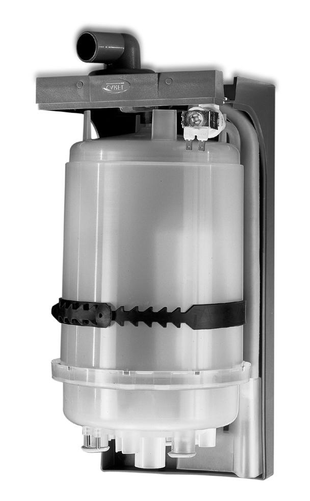
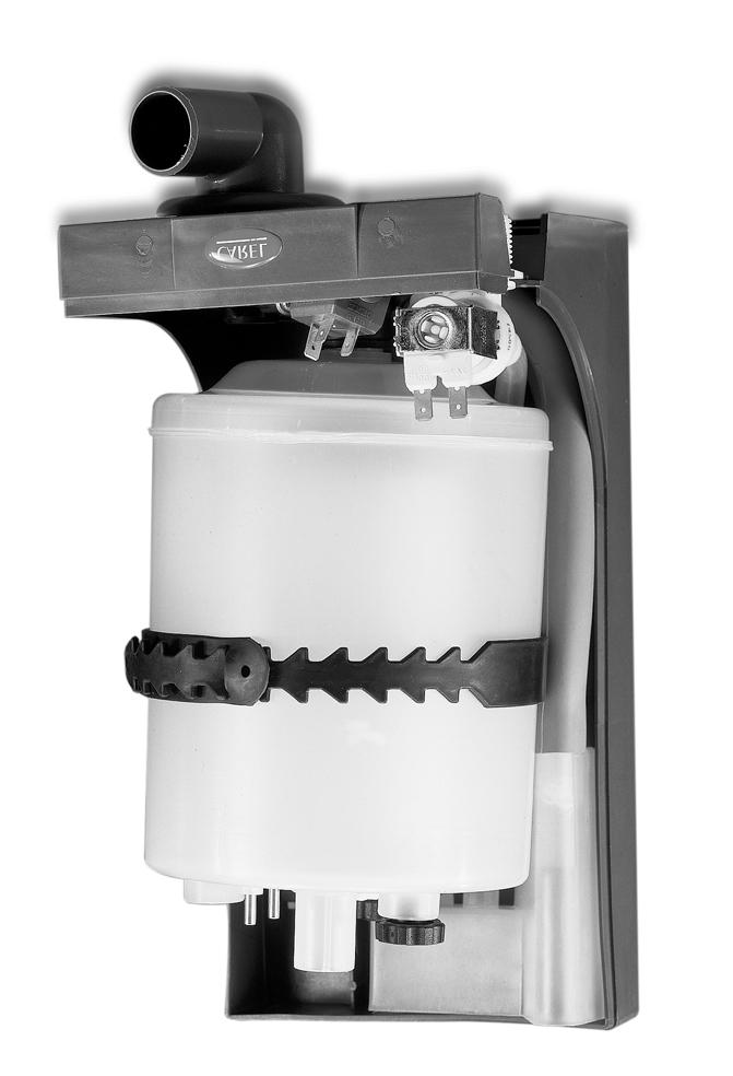
9 OEM 1. MODELS AND DESCRIPTION OF THE COMPONENTS The code that identifies the humidifier model is made up of 10 characters having the following meaning: K U E * * * * * * * Family prefix Revision level Type of power supply S= single-phase T= three-phase Size and steam production R=1.5/3 Kg/h compact 1= 1.5/3 Kg/h 2= 5/8 Kg/h 3= 10/15 Kg/h Type of cylinder Ø = disposable or w/o cylinder C = cleanable Customisation ØØ= standard vers. single package MP= standard vers. multiple package Cylinder conductivity range A B C D E (1~) F (1~) 0 = w/o cylinder Example: - KUET3D00C0 = UE OEM KIT with 15 Kg/h steam cleanable three-phase cylinder for standard conductivity, CAREL at revision level 0; - KUE010MP00 = UE OEM KIT 1.5/3 Kg/h steam - compact - w/o cylinder, with multiple package at revision level Description of the components no. description 1 Bearing frame 2 Cylinder 3 Drain solenoid valve 4 90 revolving drain connection 4a Straight drain connection (supplied) 5 Fill tank + conductivity meter 6 Fill solenoid valve Tab Fig Cod preliminary version dated 13/09/02 9
 Cod.")
10 CP* control boards (also refer to instruction sheet of the boards) OEM Fig a. Fig b. External TAM (required for CP1* and CP3* boards only) Cod preliminary version dated 13/09/02 10

11 For the description of Fig , refer to the following table. OEM no. description 1 Fill solenoid valve 2 Flow rate limiting device 3 Supply pipe 4 Fill pipe 5 Overflow pipe 6 Conductivity measuring electrodes 7 Fill tank overflow device * 8 High level electrodes 9 Steam outlet 10 Electrodes (2/6 in single-phase model, 3/6 in three-phase model) 11 Cylinder casing 12 Bottom filter 13 Drain solenoid valve Tab * Device used to prevent water overflowing from the fill tank above the safety level (e.g., due to a controller malfunction, fill solenoid valve overflowing or back pressures). Fig The fill tank is equipped with an overflow diaphragm that discharges the excess water through a special pipe. The overflow diaphragm is located in a lower position with respect to the fill one (-42mm) in order to prevent back-flow into the fill pipe. Cod preliminary version dated 13/09/02 11
12 2. INSTALLATION: dimensions, weights and pipes connection OEM 2.1 Positioning To favour steam distribution, position the appliance so as to minimise the length of the steam supply pipe. The unit has been designed for wall mounting; the wall must be able to support the weight of the unit during machine operation. The casing of the humidifier may reach temperatures above 60 C. Make sure that the humidifier is level. Raccordo di alimentazione Supply connection 3/4 Gas 3/4 Gas maschio male Raccordo di dranaggio diam. Drain connection dia. 32mm 32 mm N. 4 fori di fissaggio 6x10 No. 4 fastening holes 6x10 Cod preliminary version dated 13/09/02 12
13 Sizes and Weights OEM Models KUESR* KUE*1* KUE*2* KUE*3* Weights ( Kg ) Empty Packed Installed Dimensions (mm) H L P Ø V Ø S V V V V V S S S S S A Pipes connection A Distances X X Y Y The appliance can be either wall-mounted by using the appropriate fastening holes or installed on bracket so that the hydraulic connections can be executed. 2.2 Pipes connection The installation of the humidifier requires connection to the water supply and drain pipes. drain cock filter water supply drain trap 2.3 Drain Models KUESR* KUE*1* KUE*2* KUE*3* Max. drain instant flow rate l/min ~ 4 ~ 4 ~ 4 ~ 4 Drain water connection (mm) Drain pipe min. inside Ø Cod preliminary version dated 13/09/02 13
14 2.4 Supply Models KUE*R* KUE*1* KUE*2* KUE*3* Max. supply instant flow rate l/min Supply water connection ¾ G male ¾ G male ¾ G male ¾ G male Supply pipe min. inside Ø (rigid or flexible pipe) Tab OEM To facilitate installation, use Carel s flexible pipe with 6 mm inside diameter and 8 mm outside diameter (code APN) and the ¾ G revolving union, either straight (code ACA) or with 90 elbow (code ACA), both available on request. A cut-off cock and a mechanical filter should be installed to trap any solid impurities. The drain water connection is made using a section of rubber or plastic tubing resistant to 100 C, with 32 mm suggested inside diameter (compliant with DIN 19535, UNI 8451/8452). The drain union is suitable for heat seal with polypropylene drain pipes. IMPORTANT WARNING: the drain pipe must be free, without back pressure and must be equipped with a drain trap downstream of the connection to the humidifier. 2.5 Checks Proper hydraulic connection is obtained when the following conditions are met: installation of a cut-off cock in the supply water line; presence of a mechanical filter in the supply water line; water temperature and pressure within the allowed values; drain pipe resistant to 100 C; drain pipe minimum inside diameter corresponding to 25 mm; drain pipe minimum slope higher than or equal to 5 ; non-conductive sleeve; presence of a drain trap inside the drain pipe. IMPORTANT WARNING: upon installation completion, drain the supply pipe for approximately 30 minutes by piping the water directly into the drain connection without sending it to the humidifier. This operation allows eliminating any possible residual product that could clog the fill valve and produce foam during boiling. 2.6 Installation of the steam pipe and the condensate return pipe ƒ ƒ ƒ ƒ The humidifier must be connected to the distributor by using a pipe suitable for this purpose, such as Carel s flexible pipe. Make sure that pockets or traps are not forming, as condensate might be trapped into them. Make sure that the pipe is not choked due to sharp bends or twisting. Use screw clamps to fasten the ends of the pipe. IMPORTANT WARNING: before starting the unit, remove the PE film wrapping the pipe to allow proper heat exchange. Cod preliminary version dated 13/09/02 14
15 The pipe may run according to either of the two following solutions: OEM Steam pipe Steam condensate pipe IMPORTANT WARNING: the length of the steam pipe should not exceed 4 m. To allow the drain trap of the steam condensate pipe to operate properly, it must be filled with water prior to humidifier start-up. 2.7 Water requirements Supply water The humidifier must be supplied with aqueduct water having the following requirements: ƒ pressure between 0.1 and 0.8 MPa (1-8 bar, PSI); ƒ temperature between 1 and 40 C; ƒ instant flow rate not lower than the fill solenoid valve rated flow rate (refer to table 2.4.1); ƒ connection type ¾ G male. LIMIT VALUES FOR MEDIUM-HIGH CONDUCTIVITY SUPPLY WATER OF A LIMITS HUMIDIFIER WITH IMMERSED ELECTRODES Min Max Hydrogen ions ph Specific conductivity at 20 C σ R, 20 C - µs/cm Total dissolved solids TDS - mg/l ( 1 ) ( 1 ) Dry residue at 180 C R mg/l ( 1 ) ( 1 ) Total hardness TH - mg/l CaCO 3 100( 2 ) 400 Temporary hardness - mg/l CaCO 3 60( 3 ) 300 Iron + Manganese - mg/l Fe + Mn Chlorides - ppm Cl 0 30 Silica - mg/l SiO Residual chlorine - mg/l Cl Calcium sulphate - mg/l CaSO Metallic impurities - mg/l 0 0 Solvents, diluents, soaps, lubricants - mg/l 0 0 ( 1 ) Values depending on specific conductivity; in general: TDS 0.93 * σ 20; R * σ 20 ( 2 ) not lower than 200% of chlorides content in mg/l of Cl - ( 3 ) not lower than 300% of chlorides content in mg/l of Cl - Tab Cod preliminary version dated 13/09/02 15
16 OEM LIMIT VALUES FOR MEDIUM-LOW CONDUCTIVITY SUPPLY WATER OF A LIMITS HUMIDIFIER WITH IMMERSED ELECTRODES Min Max Hydrogen ions ph Specific conductivity at 20 C σ R, 20 C - µs/cm Total dissolved solids TDS - mg/l ( 1 ) ( 1 ) Dry residue at 180 C R mg/l ( 1 ) ( 1 ) Total hardness TH - mg/l CaCO 3 50( 2 ) 250 Temporary hardness - mg/l CaCO 3 30( 3 ) 150 Iron + Manganese - mg/l Fe + Mn Chlorides - ppm Cl 0 20 Silica - mg/l SiO Residual chlorine - mg/l Cl Calcium sulphate - mg/l CaSO Metallic impurities - mg/l 0 0 Solvents, diluents, soaps, lubricants - mg/l 0 0 ( 1 ) Values depending on specific conductivity; in general: TDS 0.93 * σ 20; R * σ 20 ( 2 ) not lower than 200% of chlorides content in mg/l of Cl - ( 3 ) not lower than 300% of chlorides content in mg/l of Cl - Tab Warning: no relation can be demonstrated between water hardness and conductivity. IMPORTANT WARNING: do not treat water with softeners! This could cause corrosion of the electrodes or the formation of foam, leading to potential operative problems or failures. Avoid: 1. using well water, industrial water or water drawn from cooling circuits; in general, avoid using potentially contaminated water, either from a chemical or bacteriological point of view; 2. adding disinfectants or corrosion inhibiters to water, as these substances are potentially irritant. 2.8 Drain water Inside the humidifier, water boils and turns into steam without the addition of any type of substance. As a result, the drain water contains the same substances that are dissolved in the supply water, yet in greater quantity, as a function of the concentration in the supply water and of the set drain cycles. The drain water can reach 100 C and ~4 l/min instant flow rate. As the drain water is not toxic, it can be drained into the white waters system. The drain connection has 32 mm outside diameter. Cod preliminary version dated 13/09/02 16

17 OEM 3. ELECTRICAL CONNECTIONS (with Carel CP control) Before executing the connections, make sure that the machine is disconnected from the mains. For further information concerning control, refer to the data sheet cod WARNING: the following signal cables must be shielded and laid apart from power cables as by EMC norms: - external regulator - remote on/off - external TAM (CP1 and CP3 only) - high level sensor - conductibility sensor 3.1 Single-phase wiring diagram EXTERNAL TAM (CP1) Cod preliminary version dated 13/09/02 17
 Cod.")
18 OEM 3.2 Single-phase wiring diagram INTERNAL TAM (CP2) Cod preliminary version dated 13/09/02 18
 OEM Cod.")
19 3.3 Single-phase wiring diagram INT. TAM with remote control switch (CP4) OEM Cod preliminary version dated 13/09/02 19
 OEM Cod.")
20 3.4 Single-phase wiring diagram EXT. TAM with remote control switch (CP3) OEM Cod preliminary version dated 13/09/02 20
 Cod.")
21 OEM 3.5 Three-phase wiring diagram EXTERNAL TAM (CP3) Cod preliminary version dated 13/09/02 21

22 OEM 3.6 Three-phase wiring diagram INTERNAL TAM (CP4) (*) material not supplied by Carel (**) no. of turns through TAM: refer to data sheet code Cod preliminary version dated 13/09/02 22
23 START-UP, CONTROL AND SHUT-DOWN IMPORTANT WARNINGS: 1. Prior to machine start-up, check that the humidifier is in good condition, that no water leak is present and that the electrical parts are dry. 2. Do not power the appliance in case it is damaged or even partially wet! Upon installation completion, drain the fill pipe for approximately 30 minutes by piping the water directly into the drain connection without sending it to the humidifier. This operation allows eliminating any possible residual product that could clog the drain valve and produce foam during boiling. OEM 4.1 Preliminary checks Before starting the humidifier, check that: the hydraulic and electrical connections and the steam distribution system have been executed according to the instructions contained in this manual; the water cut-off cock to the humidifier is open; the line fuses are installed and intact; the AB terminals of the CP control board are provided with jumper or connected to the ON/OFF remote contact; also check that the ON/OFF contact is closed; the steam outflow pipe is not choked. 4.2 Start-up Start-up with empty cylinder This phase will take place automatically when the machine is started: the rated production will be obtained after a certain period has passed (such interval depends considerably on the conductivity of the supply water and may last for some hours). Cod preliminary version dated 13/09/02 23
24 5. MAINTENANCE AND SPARE PARTS OEM 5.1 Replacing the cylinder IMPORTANT WARNING: the cylinder might be hot: before touching it, let it cool or use protective gloves. To intervene on the cylinder: completely drain the water contained in the cylinder; turn the appliance off and open the mains knife switch (safety procedure); remove the steam pipe from the cylinder; disconnect the electrical connections from the top of the cylinder; release the cylinder from the fasteners and lift it for removal; assemble the new cylinder on the humidifier operating in reverse order. Maintenance of the cylinder (refer to cylinders instruction sheet) The duration of the cylinder depends on different factors, including: complete filling with limestone and/or partial or total corrosion of the electrodes, proper use and dimensioning of the humidifier, working output, water quality, careful and regular maintenance. Due to plastics ageing and electrodes wear, even an openable steam cylinder has a limited duration in time; therefore, it is suggested to replace the cylinder after 5 years or 10,000 working hours. Important warnings The humidifier and the cylinder contain live electrical devices and hot surfaces, therefore all service and/or maintenance operations must be carried out by specialist and qualified personnel aware of the necessary precautions. Before intervening on the cylinder, make sure that the humidifier is disconnected from the mains; carefully read and follow the instructions contained in this manual. Remove the cylinder from the humidifier only after it has been drained completely. Make sure that the model and power supply voltage of the new cylinder correspond to the data of the replaced cylinder. Periodical checks After one hour of operation For both the disposable and openable cylinders, check that no significant water leak is present. Every fortnight and no more than 300 working hours For both the disposable and openable cylinders, check that no significant water leak is present and verify cylinder operation and the general conditions of the container. Also check that no arc or spark originate between the electrodes when the machine is operating. Every three months and no more than 1,000 working hours For disposable cylinders, verify cylinder operation, check that no significant water leak is present and replace the cylinder, if required. For openable cylinders, check the container for markedly blackened areas: in case they are present, check the scale condition of the electrodes and, if necessary, replace them together with the O-rings and the cover gasket. Every year and no more than 2,500 working hours For disposable cylinders, replace the cylinder. For openable cylinders, check that no significant water leak is present, verify cylinder operation and the general conditions of the container. Also check the container for markedly blackened areas: in case they are present, replace the electrodes together with the O-rings and the cover gasket. After 5 years and no more than 10,000 working hours For both the disposable and openable cylinders, replace the cylinder. After extended use or due to the use of water with a high salt content, the solid deposits that form naturally on the electrodes might spread until they cover the cylinder internal wall. In case particularly conductive deposits form, the heat consequently produced might overheat plastic and melt it; in the most severe cases, heat might perforate plastic, causing the water to leak from the cylinder to the tank. As a precaution, check the quantity of deposits and verify that no deformation or blackening is present on the wall of the cylinder, otherwise replace it. WARNING: in case of leak, disconnect the appliance before touching the cylinder, as current might be present in water. Cod preliminary version dated 13/09/02 24
25 OEM 5.2 Maintenance of the other hydraulic components IMPORTANT WARNINGS: Do not use detergents or solvents for plastic components cleaning. Scale can be removed using a solution with 20% vinegar or acetic acid and then rinsing with water. The only steam humidifier component that requires periodical replacement is the steam production cylinder. Replacement is required when the limestone deposits that form inside the cylinder prevent current from flowing properly. In this case, an alarm signal is displayed on the controller. The frequency of this operation depends on the supply water: the more water contains salts or impurities, the more cylinder replacement will be frequent. no. description 1 Bearing frame 2 Cylinder lock belt 3 Fill tank + conductivity meter 4 Overflow pipe 5 Cylinder fill pipe 6 Tank fill pipe 7 Fill solenoid valve 8 Fill/drain manifold 9 Gasket elbow drain union 11 Straight drain union (supplied) 12 Drain solenoid valve Tab Fill solenoid valve (Fig , part no. 7) After disconnecting cables and pipes, remove the solenoid valve and check cleaning of the inlet filter; if required, clean it using water and a soft brush. Fill and drain manifold (Fig , part no. 8) Check that no solid deposit is present inside the cylinder seat; remove impurities, if any. Check that the O-ring is not damaged or cracked; replace it if necessary. Drain solenoid valve (Fig , part no. 12) Cut power off, remove the coil and disassemble the valve body after having unscrewed the two screws fastening it to the manifold; remove impurities, if any, and rinse. Fill tank + conductivity meter (Fig , part no. 3) Verify that no clog or solid particle is present and check the conductivity measuring electrodes for proper cleaning; remove impurities, if any, and rinse. Supply, fill and overflow pipes (Fig , parts no. 4, 5, 6) Check the pipes for proper clearing and cleaning; remove impurities, if any, and rinse. IMPORTANT WARNING: after replacing or checking the hydraulic parts, verify the connections for proper execution. Start the machine again and carry out some fill and drain cycles (from 2 to 4); upon cycles completion, check for water leaks, if any, in compliance with the safety procedure. Fig Cod preliminary version dated 13/09/02 25
26 OEM 5.3 Replacing the components Fuses of the auxiliary circuits Use fuses with the ratings indicated in tab Models KUES1* or KUESR* KUET1* KUET2* KUET3* fuses A, GL, 10.3 x 38 contained in the fuse carriers on Omega rail fuse 3 *** 2 A, T, 5x20 Tab ***: fitted on the CP control board only. 5.4 Spare parts SINGLE-PHASE humidifiers: Standard spare parts Model KUESR* KUES1* Hydraulic part Cylinder lock belt 18C499A006 18C499A006 Fill tank + conductivity meter 13C119A003 13C119A003 Fill solenoid valve kit KITVC00006 KITVC00006 Drain solenoid valve kit 13C476A050 13C476A050 Drain unions kit KITRAC0000 KITRAC0000 Internal pipes kit * UEKT00000S UEKT00000S *: pipes must be cut at the required size before installation Non-openable cylinders VAC 1~, conductivity µs/cm BL0SRF00H0 BL0S1F00H0 Electronic part Control board ver. CP refer to data sheet code Tab Spare parts for special applications The following spare parts are supplied separately from the standard humidifier, therefore they must be ordered separately. Model KUESR* KUES1* Non-openable cylinders VAC 1~, conductivity µs/cm BL0SRE00H0 BL0S1E00H0 Tab THREE-PHASE humidifiers: Standard spare parts MODEL KUET1* KUET2* KUET3* Hydraulic part Cylinder lock belt 18C499A006 18C499A006 18C499A006 Fill tank + conductivity meter 13C119A003 13C119A003 13C119A003 Fill solenoid valve kit KITVC00006 KITVC00006 KITVC00012 Drain solenoid valve kit 13C476A050 13C476A050 13C476A050 Drain unions kit KITRAC0000 KITRAC0000 KITRAC0000 Internal pipes kit * UEKT00000S UEKT00000M UEKT00000M *: pipes must be cut at the required size before installation Non-openable cylinders VAC 3~, conductivity µs/cm 380 VAC 3~, conductivity µs/cm BL0T1D00H0 ( 230 VAC) BL0T2B00H0 BL0T2D00H0 BL0T3B00H0 BL0T3D00H0 Electronic part Control board ver. CP refer to data sheet code Tab Cod preliminary version dated 13/09/02 26
27 OEM Spare parts for special applications The following spare parts are supplied separately from the standard humidifier, therefore they must be ordered separately. MODEL KUET1* KUET2* KUET3* Non-openable cylinders VAC 3~, conductivity µs/cm BL0T1A00H0 BL0T2A00H0 BL0T3A00H0 380 VAC 3~, conductivity µs/cm BL0T2C00H0 BL0T3C00H0 Openable cylinders VAC 3~, conductivity µs/cm BLCT2A00W0 BLCT3A00W VAC 3~, conductivity µs/cm BLCT2B00W0 BLCT3B00W0 380 VAC 3~, conductivity µs/cm BLCT2C00W0 BLCT3C00W0 380 VAC 3~, conductivity µs/cm BLCT2D00W0 BLCT3D00W0 Electrodes kit ( VAC 3~, µs/cm) KITBLCT2A0 KITBLCT3A0 Electrodes kit ( VAC 3~, µs/cm) KITBLCT2B0 KITBLCT3B0 Electrodes kit ( 380 VAC 3~, µs/cm) KITBLCT2C0 KITBLCT3C0 Electrodes kit ( 380 VAC 3~, µs/cm) KITBLCT2D0 KITBLCT3D0 Electrodes gaskets kit KITBLC2FG0 KITBLC3FG0 Tab Troubleshooting table PROBLEM CAUSES SOLUTIONS 1. no electric power; The humidifier does not switch on The humidifier does not start The humidifier loads with water but does not produce steam The line magneto-thermal switch enables 2. controller connectors inserted improperly; 3. fuses disconnected; 4. transformer faulty 1. remote ON/OFF contact open (AB AB terminals) on CP control board 2. control signal not compatible with the set type 1. too high steam delivery back pressures; 2. cylinder inlet filter clogged; 3. limestone inside the supply tank; 4. drain solenoid valve faulty 1. line magneto-thermal switch under-rated 2. overcurrent to the electrodes 1. distributor installed improperly (too close to the duct top or condensate return is hindered); 1. check protection device upstream of the humidifier and verify that power supply voltage is present; 2. check connectors for proper insertion in the terminal board; 3. check condition of fuses F1/F2/F3; 4. check that voltage across the transformer secondary winding corresponds to 24 Vac 1. close ON/OFF contacts (AB AB terminals) on CP control board 2. check that the external signal is 0-10V 1. check that the steam delivery pipe is not bent or choked; 2. clean the filter; 3. clean the supply tank; 4. check 24 Vac anomalous presence on the drain solenoid valve and/or replacement of drain solenoid valve 1. check that the magneto-thermal switch has been rated for a current value corresponding to at least 1.5 times the rated current of the humidifier 2. check the operation of the drain solenoid valve, the seal of the fill solenoid valve when it is not excited, drain part of the water and start the system again 1. check the steam distributor for proper installation; The humidifier wets the duct The humidifier wets the underlying floor 2. system over-rated; 3. humidifier enabled but duct fan off 1. supply or overflow hydraulic circuit leaking; 2. steam delivery pipe not properly fastened to the cylinder 2. decrease steam production set on the control board; 3. check connection of a device (flow switch or differential pressure switch) slaving the humidifier to the ventilation inside the duct (AB AB terminals) of the CP control board 1. check the entire hydraulic circuit; 2. check fastening of the clamp on the steam delivery pipe Tab Alarms Refer to data sheet , which is an integral part of this manual. Cod preliminary version dated 13/09/02 27
28 6. OPERATING PRINCIPLES, CONTROL AND OTHER FUNCTIONS 6.1 Operating principle In a humidifier with electrodes, humidity is produced inside a cylinder (boiler) containing water that is heated to and then held at boiling temperature. The evaporated water is automatically replaced with water drawn from the supply network. The heat required for water boiling is obtained by passing electric current through the cylinder water; this operation can be executed by connecting the electrodes immersed inside the boiler to the electric supply network. The initial quantity of the flowing current strongly depends on the type of water coming from the supply network. Normally, a recently-started cylinder has low current. With the passing of time, the quantity of the salts contained in the water increases (as a matter of fact, evaporation does not include salts); this feature allows reaching the required current level so that the machine can provide for the required steam quantity. Under stable operating conditions, the required production level is automatically obtained by controlling the boiler water level. This control allows having higher or lower current levels. Part of the salts introduced in the water by the automatic refill settles inside the boiler as limestone, contributing to the progressive wear of the cylinder; the remaining salts keep dissolved in the water. In order to prevent excessive salt deposits, some water is periodically and automatically drained and then replaced with fresh water. 6.2 Control principles The range of humidifiers includes the following control options ON/OFF control Control is of on-off type and is enabled by an external contact that determines the control set-point and differential. OEM Proportional control The steam production (quantity per hour) is proportional to the value of a signal Y coming from an external device; the type of signal can be selected via RS485 through programming among the following standards: 0-10 V (default), 2-10 V, 0-1 V. The entire range is indicated as BP (proportional band). The Pmax maximum production, corresponding to the maximum value of the Y external signal, can be programmed between 20% and 100% of the humidifier rated value (dip A3-A4). The Pmin minimum production is set to 20% of the rated value, with activation hysteresis, given by the hy value, corresponding to 2% of the entire BP range of the Y external signal. Pmax P min hy hy OFF ON BP PRODUZIONE DI VAPORE Y Fig Cod preliminary version dated 13/09/02 28
29 7. TECHNICAL SPECIFICATIONS OEM MODEL KUESR* KUES1* KUET1* KUET2* KUET2* KUET3* KUET3* Steam flow (kg/h) connection (φ mm) 22/30 30 delivery pressure limits (Pa) Supply water connection G¾ temperature limits ( C) 1-40 pressure limits (MPa) (1-8 bar, PSI) hardness limits ( fh) 40 instant flow rate (l/min) conductivity range (µs/cm) 125-1,250 Drain water connection (φ mm) 32 typical temperature ( C) 100 instant flow rate (l/min) ~ 4 Environmental conditions operating ambient temperature ( C) 1-50 operating ambient humidity (% rh) storage temperature ( C) storage humidity (% rh) 5-95 index of protection (CEI EN 60529) IP00 Electronic control (also refer to CP control board data sheet cod ) type CP1*, CP2*, CP3*, CP4* auxiliary circuits voltage/ frequency (VAC/Hz) 24VAC (-15% TO +10%) / 50-60Hz auxiliary circuits maximum power (VA) 30 signal input input impedance for 0-10V, 2-10V, 0-1V voltage signals: 15 kω Electrical ratings: refer to data sheet cod Carel reserves the right to modify or change its products without prior notice. Cod preliminary version dated 13/09/02 29
30 OEM Remarks:
31 OEM
32 OEM Agency: CAREL S.p.A. Via dell Industria, Brugine - Padova (Italy) Tel. (+39) Fax (+39) carel@carel.com Cod: preliminary version 13/09/02
We want you to save time and money! We assure you that the thorough reading of this manual will guarantee proper installation and safe use of the
 2(0 User manual We want you to save time and money! We assure you that the thorough reading of this manual will guarantee proper installation and safe use of the described product. IMPORTANT WARNINGS
We wish to save you time and money! We can assure you that the thorough reading of this manual will guarantee correct installation and safe use of
 User manual We wish to save you time and money! We can assure you that the thorough reading of this manual will guarantee correct installation and safe use of the product described. IMPORTANT WARNINGS
BUILT IN IMMERSED ELECRODES HUMIDIFIER USER MANUAL
 BUILT IN IMMERSED ELECRODES HUMIDIFIER USER MANUAL THIS MANUAL REFERS TO THE FOLLOWING UNITS: DIRECT EXPANSION AND CHILLED WATER AIR CONDITIONERS WHIT ACCESSORY INTERNAL HUMIDIFIER www. tecnairlv. it info
humisteam Basic humidifiers User manual
 humisteam Basic humidifiers User manual I n t e g r a t e d C o n t r o l S o l u t i o n s & E n e r g y S a v i n g s WARNINGS The CAREL humidifiers are advanced products, whose operation is specified
humidifi cation for life
 humidifi cation for life Product selection catalogue air humidifi cation products and systems CAREL humidification solutions What is humidity? Humidity is simply the presence of water vapour in the air.
HU315 HUMIDIFIER SERIES
 Simplified INSTALLATION MANUALand Detailed Installation manual are included in this package. HUMIDIFIER SERIES Note: has replaced the HU313 as of Jan. 1, 2005 Filename: Quatro/ 03/05/04 QUATRO SIMPLIFIED
Thermoelectric Bath. Series HEB
 Peltier-Type Thermoelectric Bath Accurately controls the temperature of liquid in the bath. Temperature stability: ±0.018 F Temperature distribution: ±0.036 F in the bath Environmentally friendly and refrigerant-free
compactsteam residential/light commercial steam humidifiers User manual
 residential/light commercial steam humidifiers User manual We wish to save you time and money! We can assure you that the thorough reading of this manual will guarantee correct installation and safe use
Water atomiser through compressed air
 Water atomiser through compressed air I n t e g r a t e d C o n t r o l S o l u t i o n s & E n e r g y S a v i n g s Water atomiser through compressed air The mc multizone adiabatic humidification system
HEB Series. Peltier-Type Thermoelectric Bath
 Peltier-Type Thermoelectric Bath HRS090 HRZD HRZ HRSE HRSH Environmentally friendly and refrigerant-free Heaterless Function to detect abnormal heating and temperature sensor errors comes standard. Light
HUMIDIFIER EQQA, EQQZ
 HUMIDIFIER EQQA, EQQZ INSTALLATION AND MAINTENANCE INSTRUCTION EQQA Once-through water 2- EQQA for circulated water.. 6-1 EQQZ-1 Humidifier cassette Ordering code. 16 EQQA Once-trough water EQQA for circulated
Installation & User Manual Duct Models
 Installation & User Manual Duct Models FORM NO. 25-32; Rev. A 1. Duct Steam Humidifier 2. Installation manual 3. Mounting template 4. Installation Kit a. Steam nozzle b. 6 Steam hose c. 9 Condensate hose
Thermoelectric Bath. Series HEB
 Peltier-Type Thermoelectric Bath Series HEB Accurately controls the temperature of liquid in the bath. Temperature stability: ±0.018 F Temperature distribution: ±0.036 F in the bath Environmentally friendly
DS 50 / DS 50 LC Elite Steam Residential Humidifiers. User manual. Revision 1.2
 DS 50 / DS 50 LC Elite Steam Residential Humidifiers User manual Revision 1.2 Warning If present, remove the following items: IMPORTANT WARNINGS We wish to save you time and money! We can assure you that
Wallace & Tiernan Gas Feed Systems V2000 Chlorinator
 Wallace & Tiernan Gas Feed Systems V2000 Chlorinator Introduction Siemens Water Technologies chlorination equipment has the benefit of 100 years of experience in gas feed technology. V2000 chlorinators
Instruction Manual - Anti-Siphon Ejector Chlorine & Sulfur Dioxide 500 PPD (10 kg/h) Maximum Capacity
 Maximum Capacity") - Anti-Siphon Ejector Chlorine & Sulfur Dioxide 500 PPD (10 kg/h) Maximum Capacity 100 PPD (2 kg/h) Chlorine or Sulfur Dioxide 250 & 500 PPD (5 & 10 kg/h) Chlorine or Sulfur Dioxide Anti-Siphon Ejector
- Anti-Siphon Ejector Chlorine & Sulfur Dioxide 500 PPD (10 kg/h) Maximum Capacity 100 PPD (2 kg/h) Chlorine or Sulfur Dioxide 250 & 500 PPD (5 & 10 kg/h) Chlorine or Sulfur Dioxide Anti-Siphon Ejector
I/O logger box. User manual NO POWER & SIGNAL CABLES TOGETHER READ CAREFULLY IN THE TEXT!
 I/O logger box User manual NO POWER & SIGNAL CABLES TOGETHER READ CAREFULLY IN THE TEXT! H i g h E f f i c i e n c y S o l u t i o n s WARNING DISPOSAL CAREL bases the development of its products on decades
541D19 SERIES. Technical Manual. A Division of Aquion Partners L.P.
 541D19 SERIES Technical Manual A Division of Aquion Partners L.P. Table of Contents Introduction... Page 1 Technical Specifications... Page 2 Flow Diagrams... Page 3 Injector & Flow Control Selection Injector...
TECHNICAL MANUAL ASGX
 TECHNICAL MANUAL ASGX MEDIUM/HIGH PRESSURE HOT WATER BOILER INDEX 1 TECHNICAL CHARACTERISTICS... 2 1.1 GENERAL... 2 1.2 TECHNICAL DATA... 2 2 ACCESSORIES... 3 2.1 PRESSURE... 3 Pressure gauge... 3 Operation
VAPORELLA. Fig. 1 Fig. 2. Fig. 3 Fig. 4
 3b 3 1 6 3a 4 2 7 8 9 5 Fig. 1 Fig. 2 Fig. 3 Fig. 4 1) Iron temperature adjustment knob 2) Boiler ON/OFF switch 3) Steam button 3a) Iron heating indicator light 3b) Continuous steam jet button 4) Iron
PUROTAP easy. Installation Function Operation Service. fast efficient safe. Demineralised heating water perfect for every system
 EN Demineralised heating water perfect for every system PUROTAP easy Installation Function Operation Service fast efficient safe Minerals and salts in technical water circulations lead to corrosion and
Polti S.p.A. reserves the right to change equipment or accessory specification without prior notice.
 Daisy R 1) Iron temperature adjustment knob 2) Boiler ON/OFF switch 3) Steam button 3a) Iron heating indicator light 3b) Pressure indicator light 3c) Continuous steam jet button 4) Iron on/off switch 5)
heatersteam unprecedented precision and reliability
 heatersteam unprecedented precision and reliability Electric heater humidification Reliable and precise technology for high-tech applications. Steam production is modulated with the highest precision,
G-10s. Instruction Manual. G-Series Cooler UPRIGHT COOLER. Part No.11IPA
 G-Series Cooler UPRIGHT COOLER Part No.11IPA-062800 Instruction Manual FOR YOUR FUTURE REFERENCE Thank you for using our product. This manual will guide you in getting the best use of your cooler. Remember
LQQA Humidifier, for circulated water
 Size -84 5 Fig. 4 5 4 6 8 7 9 7 8. Control box, on the outside. Control box, on the inside. Shut-off valve (not included) 4. Water filter, max. 5 mm mesh (not included) 5. LQAZ-8 Water trap (accessory)
INSTRUCTIONS FOR INSTALLATION AND MAINTENANCE (GB)
") INSTRUCTIONS FOR INSTALLATION AND MAINTENANCE (GB) Pag. 1 Fig - Fig. - Abb.- Fig.- Fig.- Фиг.- Obr.- Fig.- Εικ. - Joonis - Kuva - Sl. -.ábra - Fig. -.att. - Afbeelding - Fig. - Rys.- Fig.- Fig. - Схема
INSTRUCTIONS FOR INSTALLATION AND MAINTENANCE (GB) Pag. 1 Fig - Fig. - Abb.- Fig.- Fig.- Фиг.- Obr.- Fig.- Εικ. - Joonis - Kuva - Sl. -.ábra - Fig. -.att. - Afbeelding - Fig. - Rys.- Fig.- Fig. - Схема
ASPIRE Laboratory Aspirator
 ASPIRE Laboratory Aspirator USER MANUAL Rev 2/14/18 Accuris Instruments / Benchmark Scientific Ph: (908) 769-5555 E-mail: info@accuris-usa.com (C) Benchmark Scientific, 2018 THE ACCURIS ASPIRE LABORATORY
Electrostatic Precipitator
 Electrostatic Precipitator ESP1500E ESP3000E ESP4500E TECHNICAL & OPERATION MANUAL This manual refers to:- Model ESP1500E Serial No. E152014 Model ESP3000E Serial No. E302014 Model ESP4500E Serial No.
Glass and Dishwashers 402/452/502. (original instructions) (incl. Australian /502) Starting from Serial No.:
 (incl. Australian /502) Starting from Serial No.:") Glass and Dishwashers ECOMAX 402/452/502 (incl. Australian 452-90/502) INSTALLATION AND OPERATION INSTRUCTIONS (original instructions) Starting from Serial No.: 8663 4000 REV. 05.10.2015 EN IMPORTANT NOTES
Glass and Dishwashers ECOMAX 402/452/502 (incl. Australian 452-90/502) INSTALLATION AND OPERATION INSTRUCTIONS (original instructions) Starting from Serial No.: 8663 4000 REV. 05.10.2015 EN IMPORTANT NOTES
Elite Steam Residential Steam Humidifiers. User manual. Revision 3.5
 Elite Steam Residential Steam Humidifiers User manual Revision 3.5 LATCH THE CYLINDER CLAMP Warning If present, remove the following items: REMOVE BEFORE INSTALLING REMOVE BEFORE INSTALLING REMOVE BEFORE
9.0 Systems For Domestic Water Installations
 9.0 Systems For Domestic Water Installations 9.0.1Equipment Catalogue 2009 9.0.1 Proportional Flow Dosing System For Liquid Dosing turbodos, DULCODOS metering systems protect pipework, fittings, and devices
Quick Start Installation Guide
 Quick Start Installation Guide Nortec EL Electrode Steam Humidifier Overview Mounting Installation Requirements Standard Mounting Steam Distribution Installation Requirements Plumbing Water and Drainage
heatersteam unprecedented precision and reliability
 heatersteam unprecedented precision and reliability Electric heater humidification Reliable and precise technology for high-tech applications. Steam production is modulated with the highest precision,
HEB Series. Thermoelectric Bath
 Peltier-Type Thermoelectric Bath HEB Series Accurately controls the temperature of liquid in the bath. Temperature stability: ±0.01 C Temperature distribution: ±0.02 C in the bath RoHS 100/150 Environmentally
Light oil burners. One stage operation
 Installation, use and maintenance instructions Light oil burners One stage operation CODE MODEL TYPE 3505 RDB CF 38 50 T3 350050 RDBR CF 6 50 TR 35050 RDBR CF 33 50 TR 35050 RDBR CF 38 50 T3R 350650 RDBR
POWERFLOW Series. Unvented Electric Storage Water Heaters. Installation & Operating Instructions Manual
 POWERFLOW Series Unvented Electric Storage Water Heaters Installation & Operating Instructions Manual These Instructions must be left with the user after installation. Version 3.0 June 2009 Hyco POWERFLOW
BarAid 400. Installation and. Starting from Serial No.:
 Glasswasher BarAid 400 Installation and operation Instructions Starting from Serial No.: 8649 1065 REV. 19.01.2009 DE 1618-A-01-09 Content Page 1 Important Notes... 4 2 Installation... 5 2.1 Location...
EUQA Humidifier, for circulated water
 Sizes 0 4, 50, 5 Sizes 44, 5 84 6 5 4 6 5 4 5 6 8 7 9 7 8 0. Control box, on the outside. Control box, on the inside. Shut-off valve (not included) 4. Water filter, max. 500 mm mesh (not included) 5. EUAZ-08
Mod. ANBR9..G. CR DOC. NO. GAS-HEATED TILTING BRATT PAN. INSTRUCTIONS FOR INSTALLATION, ADJUSTMENT, USE AND MAINTENANCE...
 -HEATED TILTING BRATT PAN Mod. ANBR9..G. INSTRUCTIONS FOR INSTALLATION, ADJUSTMENT, USE AND MAINTENANCE...page 2-5 APPENDIX....pagina 6-7 Read the manual thoroughly and keep it in a safe place throughout
ES Series Electric Humidifier
 Read and Save These Instructions Standard Water ES Series Electric Humidifier Installation Instructions Operation and Maintenance Manual ETL LISTED HUMIDIFIER Our results are comforting Form No: ESOM-08-08
Operating Manual. Reverse Osmosis Water Purifier. MELAdem 55
 Operating Manual Reverse Osmosis Water Purifier MELAdem 55 Dear Doctor, Thank you for placing your trust in this reverse osmosis water purifier. Since 1951, MELAG has specialised in the production of sterilisation
Rif Cod i220-0
 15 52 50 6 13 53 51 2 9 8 3 20 19 18 5 1 7 14 10 4 17 Rif Cod 1 0010060 2 0060287 3 0060310 4 0080003 5 0080004 6 0080051 7 0080053 8 0080410 9 0080413 10 0080430 11 0080432 12 0080434 13 0080435 14 0080436
Glass and Dishwashers AMX / AUX Series
 Glass and Dishwashers AMX / AUX Series INSTALLATION OPERATION REV. 8.xx 04.07.2005 Installation and Operation Instructions for Models of AMX / AUX Series Content Page 1 Installation... 3 2 Connections...
G-7s. Instruction Manual. G-Series Cooler COUNTERTOP COOLER. Part No.11IPA
 G-Series Cooler COUNTERTOP COOLER Part No.11IPA-061000 Instruction Manual FOR YOUR FUTURE REFERENCE This easy-to-use manual will guide you in getting the best use of your cooler. Remember to record the
AGITATOR V DO NOT OPERATE THE MACHINE UNTIL YOU HAVE READ ALL SECTIONS OF THESE INSTRUCTIONS IMPROPER USE OF THE MACHINE WILL VOID THE WARRANTY
 AGITATOR 20 120V INFORMATION & OPERATING INSTRUCTIONS DO NOT OPERATE THE MACHINE UNTIL YOU HAVE READ ALL SECTIONS OF THESE INSTRUCTIONS IMPROPER USE OF THE MACHINE WILL VOID THE WARRANTY 1. Always use
ENERGY TOP. Condensing boiler solutions
 ENERGY TOP Condensing boiler solutions 1 ENERGY TOP > ENERGY TOP RANGE A wide array of flexible solutions both for centralised residential application and big commercial plants The increasing need for
Granule Gastro/Combi
 Granule Gastro/Combi Spare parts list Granule Gastro serial # 710010- Granule Combi serial # 810010- Art. No. EN 21111-2010-03. GRANULDISK AB retains the right to make technical changes to the products.
CHH30 Dishwasher. Wiring Diagram. Spare Parts List. Installation / Operation
 CHH30 Dishwasher Installation / Operation Spare Parts List Wiring Diagram jw-06-2006 GB USE AND MAINTENANCE MANUAL Pag. 1 CONTENTS CHAP. 1 INTRODUCTION... 3 CHAP.2 INSTALLATION... 3 2.1 HANDLING AND UNPACKING...
LQQA Humidifier, for circulated water
 Size 5 Fig. 6 5 6 8 7 9 7 8. Control box, on the outside. Control box, on the inside. Shut-off valve (not included). Water filter, max. 5 mm mesh (not included) 5. LQAZ-8 Water trap (accessory) 6. Water
Installation and operating instructions. DK energy storage and DK energy buffer
 Installation and operating instructions DK energy storage and DK energy buffer Edition: 08-2015 1 Preliminary note With this DK energy storage / DK energy buffer you purchased a DK quality product. The
ME SERIES ELECTRICALLY OPERATED BOILERS INSTALLATION - OPERATION - MAINTENANCE MODELS
 ME SERIES ELECTRICALLY OPERATED BOILERS INSTALLATION - OPERATION - MAINTENANCE MODELS M24E M36E Telephone: (802) 658-6600 Fax: (802)864-0183 www.marketforge.com PN 14-0309 Rev G (11/17) 2017 - Market Forge
MODEL 7000 SUCTION UNIT
 MODEL 7000 SUCTION UNIT OPERATOR S MANUAL Caution Federal law restricts this device to sale by or on order of a physician, or any other practitioner licensed by the law of the State in which he practices
CALEFFI. Set point thermostatic regulating unit. 182 series 01190/18 GB. replaces dp 01190/15 GB
 Set point thermostatic regulating unit 8 series FM 65 00 CALEFFI 090/8 GB replaces dp 090/5 GB Function The thermostatic regulating unit is made to be used in radiant panel systems, in combination with
GCG-10. Instruction Manual. G-Series Cooler. Manual is for the following models: GCG-10-N33EB G-10-N33EB UPRIGHT COOLER
 G-Series Cooler GCG-10 UPRIGHT COOLER Manual is for the following models: GCG-10-N33EB G-10-N33EB Instruction Manual Manual is for the following models: GCG-10-N33EB G-10-N33EB Instruction Manual GCG-10
Powerflow Unvented water heater
 Product Instruction Manual Powerflow Unvented water heater 30, 50 and 90 litres v15.6/5 Thank you for purchasing a Powerflow series unvented electric water heater. The Powerflow is suitable for hand washing
GCG-9. Instruction Manual. G-Series Cooler. Manual is for the following models: GCG-9-N13EB G-9-N13EB GCG-9-B13EB UPRIGHT COOLER
 G-Series Cooler UPRIGHT COOLER Manual is for the following models: -N13EB G-9-N13EB -B13EB Instruction Manual FOR YOUR FUTURE REFERENCE This easy-to-use manual will guide you in getting the best use of
Spectrum TM. Installation, Service & Operation Manual O FLO. SoftH 2. Water Softener. Table of Contents
 Installation, Service & Operation Manual SoftH 2 O FLO Water Softener Table of Contents 1. Description & Equipment Adjustments p.2 2. Components, Features & Functions p.3 3. Valve User Interface p.4 4.
_C_EN_1612 INSTALLATION, OPERATION AND MAINTENANCE MANUAL. Blower Pack Condair BP. Humidification and Evaporative Cooling
 2582479_C_EN_1612 INSTALLATION, OPERATION AND MAINTENANCE MANUAL Blower Pack Condair BP Humidification and Evaporative Cooling Thank you for choosing Condair Installation date (DD/MM/YYYY): Commissioning
.4 Section Ductwork Low Pressure Metallic to 500 Pa..3 ANSI/ARI 640 Commercial and Industrial Humidifiers.
 Issued 2006/08/01 Section 15751 Humidifiers Page 1 of 7 PART 1 GENERAL 1.1 RELATED SECTIONS.1 Section 01330 Submittal Procedures..2 Section 01780 Closeout Submittals..3 Section 01810 Commissioning..4 Section
INSTALLATION AND MANINTENANCE INSTRUCTIONS
 INSTALLATION AND MANINTENANCE INSTRUCTIONS Appr. Nr. A 9503 T - 0085 AQ 0765 PEGASUS F2 T HIGH EFFICIENCY GAS-FIRED CAST-IRON BOILERS Models 51-68 - 85-102 2 Contents 1. General technical data 2. Dimensional
G-10f/GCG-10f UPRIGHT COOLER
 G-Series Cooler G-10f/GCG-10f UPRIGHT COOLER Manual is for the following models: G-10F, G-10-F33EB GCG-10F, GCG-10-F33EB GCG-10F2, GCG-10-F233EB G-10-F33EB-HC, GCG-10-F33EB-HC GCG-10-F233EB-HC Instruction
Installation and Operation Manual IDRA PLUS DS. Solar Solar storage cylinder. Installation and Operation Manual
 Installation and Operation Manual IDRA PLUS DS Solar Solar storage cylinder EN Installation and Operation Manual GENERAL INFORMATION This - comprises pages. Rev. manual, Code ENGLISH General information
Owner s Manual RD432-0 Chemical Controller
 Owner s Manual RD432-0 Chemical Controller Table of Contents I. Introduction page 2 A. Water Chemistry page 2 B. Safety page 3 C. System Components page 4 D. Specifications page 7 E. Controller Panel Descriptions
WET/DRY VACUUM. QUEST for Continuous Improvement Windsor s Quality Management System is Certified ISO MODEL: T1. Operating Instructions (ENG)
") WET/DRY VACUUM Operating Instructions (ENG) MODEL: T1 y QUEST for Continuous Improvement Windsor s Quality Management System is Certified ISO 9001. Read these instructions before operating the machine.
WET/DRY VACUUM Operating Instructions (ENG) MODEL: T1 y QUEST for Continuous Improvement Windsor s Quality Management System is Certified ISO 9001. Read these instructions before operating the machine.
MultiMeter 44. Transmitter-regulator with 1, 2 or 3 channels. Quality at a reasonable price
 MultiMeter 44 Transmitter-regulator with 1, 2 or 3 channels MultiMeter 44 is a modular meter that can be configured with one, two or three channels. It can be delivered with only one measuring channel,
CAREL heatersteam Electric Element Steam Humidifiers
 Suggested Engineering Specifications Section 23 84 13 CAREL heatersteam Electric Element Steam Humidifiers 1. GENERAL SCOPE 1. Furnish and install as indicated on the drawings and plans, in-duct [space]
Installation & Operating Guide
 5-036 HOT WATER TANK Installation & Operating Guide Read all instructions thoroughly. Keep this guide for future reference. Proof of purchase is required for Warranty. Staple receipt or proof of purchase
Pump WaterVISE, FloVISE
 General information It is important that this manual is read carefully by the user and the installer in order to ensure proper functioning and lifespan of the pump. Pahlen pumps are manufactured in accordance
VMS-3. Part Number: Ultraviolet Systems VMS-3. Installation, Operation & Maintenance
 VMS-3 Part Number: 95-0031 Ultraviolet Systems VMS-3 Installation, Operation & Maintenance The following are the types of flags used in this technical manual. They designate safety related items and important
RC411 Operator Manual
 RC411 Operator Manual Page 1 of 14 FOREWORD 1. Read the instructions contained in the enclosed booklet carefully, because it contains important information on installation, operation and maintenance safety.
Glass and Dishwashers AMX / AUX Series
 Glass and Dishwashers AMX / AUX Series INSTALLATION OPERATION VERSION 24.02.04 Important Notes Use in Accordance with Regulations This machine is exclusively to be used to wash ware such as plates, cups,
TYPICAL INSTALLATION Figure A. Condensate Return Line. Humidifier Cabinet. Drain Line
 READ AND SAVE THESE INSTRUCTIONS MODEL HRAA TECHNICAL MANUAL INSTALLATION, OPERATION AND MAINTENANCE INSTRUCTIONS CARNES COMPANY, 448 S. Main St., P. O. Box 930040, Verona, WI 53593-0040 - Phone: 608/845-6411
SATK50-60 series CONTENTS. Recess Mounted Heat Interface Unit - SATK series INSTRUCTIONS FOR INSTALLATION, COMMISSIONING AND MAINTENANCE
 780EN www.caleffi.com Recess Mounted Heat Interface Unit - SATK series SATK0-60 series INSTRUCTIS FOR INSTALLATI, COMMISSIING AND MAINTENANCE Function The SATK series HIU allows independent control of
SMART EVO 2 - User Manual ELECTRICAL PANEL FOR 2 MOTORS
 SMART EVO 2 - User Manual ELECTRICAL PANEL FOR 2 MOTORS CONTENTS 1. INTRODUCTION... 5 2. WARNINGS... 6 3. GENERAL DESCRIPTION... 7 4. INSTALLATION... 8 5. LUMINOUS INDICATORS AND COMMANDS... 9 6. DIP-SWITCH
Installation & Operating Guide
 HOT WATER DISPENSER Installation & Operating Guide Read all instructions thoroughly. Keep this guide for future reference. Proof of purchase is required for Warranty. Staple receipt or proof of purchase
Digital Salt / TDS Meter. 390a. The Value Leader TM
 Digital Salt / TDS Meter 390a The Value Leader TM www.tpi-thevalueleader.com Contents Before Use... 1 Description... 1 Applications... 1 Precautions... 2 Overview... 3 Functions... 4 LCD Symbols... 5 Specifications...
TEMPLATE ASSISTED CRYSTALLIZATION. Presented By Ryan Lessing 11/13/2014
 TEMPLATE ASSISTED CRYSTALLIZATION Presented By Ryan Lessing 11/13/2014 Different Forms of Hardness in Water Calcium and Magnesium Bicarbonate- This is what is referred to as temporary hardness. Once it
mc multizone simple and robust, ideal for large industrial environments
 mc multizone simple and robust, ideal for large industrial environments The compressed air adiabatic humidifier Ideal for medium/large industrial environments, or in ducts in air handling units guaranteed
SCD. SMALL CYLINDER DRYER with Touchscreen Controller INSTRUCTION MANUAL MANUAL NUMBER Issued March 2015
 SCD SMALL CYLINDER DRYER with Touchscreen Controller INSTRUCTION MANUAL MANUAL NUMBER 21-11-1042 Issued March 2015 Copyright 2015, Galiso, Inc. 22 Ponderosa Ct., Montrose, CO 81401 (970) 249-0233 (800)
lindab we simplify construction Lindab Modular air handling units Connection, start-up and commissioning manual
 Lindab Modular air handling units Connection, start-up and commissioning manual Connection, start-up and commissioning manual 1 General... 3 2 Warnings and Tips... 3 3 Functional sections... 3 3.1 Fan
ADVANTAGE-100H-SC EXTRACTOR
 ADVANTAGE-100H-SC EXTRACTOR 120V INFORMATION & OPERATING INSTRUCTIONS CAUTION: DO NOT OPERATE MACHINE UNTIL YOU HAVE READ ALL SECTIONS OF THIS INSTRUCTION MANUAL IMPROPER USE OF THE MACHINE WILL VOID THE
MiniVap Humidifier Models LMV2 & LMV4
 Ä MiniVap Humidifier Models LMV2 & LMV4 Please read these Instructions BEFORE Installation and Start-up Failure to observe manufacturer s recommendations may invalidate warranty Vapac Humidity Control
HAVABLACK S2G BLACK OXIDE SALTS FOR IRON & STEEL
 BLACK OXIDE SALTS FOR IRON & STEEL produces a jet black ferro-ferric oxide (Fe304) film on ferrous alloys that when coated with oil, lacquer or waxes, provides moderate corrosion protection to 20% salt
GCG-26c. Instruction Manual. G-Series Cooler
 G-Series Cooler UPRIGHT COOLER Manual is for the following models: GCG-26-C14N7 GCG-26-C14NG GCG-26-C14NI GCG-26-C14NM GCG-26-C14NJ GCG-26 G-26-C14N7 G-26-C14NG G-26-C14NI G-26-C14NM G-26-C14NJ G-26 Instruction
PEGASUS F2 N 2S. CAST IRON GAS BOILER for heating with electronic ignition and flame control INSTRUCTIONS FOR USE, INSTALLATION AND MAINTENANCE
 PEGASUS F2 N 2S CAST IRON GAS BOILER for heating with electronic ignition and flame control INSTRUCTIONS FOR USE, INSTALLATION AND MAINTENANCE cod. 3544309/0 ediz. 01/2003 Carefully read the warnings in
INSTALLATION, OPERATION AND SERVICE MANUAL GAS COOKER MODEL CPG. Page 1 / 18
 INSTALLATION, OPERATION AND SERVICE MANUAL GAS COOKER MODEL CPG Page 1 / 18 CHAP 1 - INSTRUCTIONS TO PREVENT ACCIDENTS Keep this manual carefully to be able to refer to it in every case of need. Keep appliance
SAFETY PRECAUTIONS. 2) Before operating machine: - Make sure all safety devices are in place and operate properly.
 Before operating machine: - Make sure all safety devices are in place and operate properly.") TABLE OF CONTENTS Machine Components Safety Precautions Machine Set Up Machine Operation Machine Maintenance & Storage Troubleshooting Technical Specifications Parts Lists Wiring Diagram 1 2 3 3-4 5 6
TABLE OF CONTENTS Machine Components Safety Precautions Machine Set Up Machine Operation Machine Maintenance & Storage Troubleshooting Technical Specifications Parts Lists Wiring Diagram 1 2 3 3-4 5 6
Key benefits. Why Condair CP3?
 Condair Cp3 Humidification The Electrode Steam Humidifier. Powerful and User-Friendly Why? Tailored technology. You can program your specifications exactly to the last kilogram with the CP3 Card. This
LE Series. Electrode Steam Humidifiers
 LE Series Electrode Steam Humidifiers Electrode Steam Humidifiers The Company For over 35 years, Vapac has been designing, manufacturing and specializing in high quality solutions for indoor air humidification
SERVICE REQUIREMENTS
 SERVICE REQUIREMENTS WARNING! Read and understand the contents of this manual before attempting to service WL270 Water Treatment System. Failure to follow the instructions in this manual could result in
Case Study and 700 HP Steam Boilers - Scale
 Case Study - 600 and 700 HP Steam Boilers - Scale Case study updated on June 10, 2013 Installer: MBI Water Solutions - HydroFLOW Master Distributor in the US Pacific Northwest. Customer: Chemical Plant
Concise catalogue Water-Industry
 2008 Concise catalogue Water-Industry One-channel instruments to measure ph, EC, DO and free chlorine, panel and wall-mounting version. Transmitters - controllers very easy to utilize, the customer does
Condair CS 2.0/4.0. Resistive Humidifiers INSTALLATION AND OPERATING INSTRUCTIONS. HLK Version HLK EN 1408
 Condair CS 2.0/4.0 Resistive Humidifiers INSTALLATION AND OPERATING INSTRUCTIONS 2545546 HLK EN 1408 HLK Version 2 3 Contents 1 Introduction 4 1.1 To the very beginning 4 1.2 Notes on the installation
CALEFFI. Anti-condensation circulation unit. 282 series 01225/14 GB. replaces dp 01225/11. Code completion Setting 45 C 55 C 60 C 70 C.
 Anti-condensation circulation unit 8 series ACCREDITED ISO 9 F 654 ISO 9 No. CALEFFI 5/4 GB replaces dp 5/ Function The anti-condensation circulation unit performs the function of connecting the solid
Humidity matters! CAREL solutions for your humidification needs. carel.com. air humidification systems. isothermal and adiabathic humidification
 air humidification systems isothermal and adiabathic humidification Humidity matters! CAREL solutions for your humidification needs carel.com I n t e g r a t e d C o n t r o l S o l u t i o n s & E n e
Tier1 Water Home Filtration System
 Tier1 Water Home Filtration System Salt-Free Softener OWNERS MANUAL BEFORE YOU BEGIN INSTALLATION, READ THIS ENTIRE MANUAL. FOLLOW THE INSTALLATION INSTRUCTIONS CAREFULLY. 1. Avoid pinched o-rings during
Tornado Operations & Maintenance Manual
 TORNADO INDUSTRIES 7401 W. LAWRENCE AVENUE CHICAGO, IL 60706 (708) 867-5100 FAX (708) 867-6968 www.tornadovac.com Tornado Operations & Maintenance Manual MODEL NO. 99690 BD 22/14, 99720 BD 26/14 L9722
BC3250. Blowdown Controller
 Local regulations may restrict the use of this product to below the conditions quoted. In the interests of development and improvement of the product, we reserve the right to change the specification without
User Manual. 2 & 3 Bowl Juice Dispenser. Please read and keep these instructions. Indoor use only. 1
 2 & 3 Bowl Juice Dispenser Models: RBD-32, RBD-33 Please read and keep these instructions. Indoor use only WWW.AvantcoEquipment.com 1 Index General information... 3 Parts overview and technical data...
ELECTRIC WATER BOILER
 JJ3 ELECTRIC WATER BOILER OWNER S MANUAL Click here for Parts List Manual Part No: 930150-01 Electric Water Boiler - 1 Model No. Product Description Rev. Date Jackson Junior Boiler JJ3 Jackson Junior Boiler