NR-B30FX1 TABLE OF CONTENTS. Refrigerator-Freezer. Model No. NR-B30FG1. E: Europe Continental, B: U.K.
|
|
|
- Cori Bennett
- 5 years ago
- Views:
Transcription


1 Order Number PHARW CE Refrigerator-Freezer Model No. NR-B30FG1 NR-B30FX1 Product Color Destination W: White, X: Stainless E: Europe Continental, B: U.K. TABLE OF CONTENTS PAGE 1 Safety Precautions Specifications General/Introduction Features and Functions Technical Descriptions Location of Controls and Components Installation Instructions Test Control Service Mode Troubleshooting Guide Disassembly and Assembly Instructions Maintenance PAGE 13 Dimensions Schematic Diagram Exploded View and Replacement Parts List Panasonic Co., Ltd. All rights reserved. Unauthorized copying and distribution is a violation of law.
2 1 Safety Precautions The following are instructions that you must follow in order to prevent accidents during work, and to ensure the safety of the repaired product. Hazard and damages that may result from ignoring instructions are classified and explained, below. This section warns of the urgent danger of death or serious injury. This section warns of the risk of death or serious injury. This section warns of the risk of injury or damage to property. The following labels describe the types of rules that need to be followed. This label shows a reminder action to be paid attention to. This label shows a prohibited action. This label shows a compulsory action to be followed without fail. Be sure to discharge remaining refrigerant from the refrigeration unit. Discharge refrigerant outdoors where there is no fire source. Be sure to instruct the customer not to approach the place of discharge, and not to use fire. Always use a pipe cutter for removing pipes. If you use a welding machine, the refrigerant remaining in the pipe or compressor could catch fire and explode. Pipes must be blown out with nitrogen before welding, to discharge any remaining refrigerant. Always use the swage lock for sealing after filing with refrigerant. If you use a welding machine, the refrigerant could catch fire and explode. Ventilation close to the floor surface is required, as the refrigerant(r600) is heavier than air. In particular, the basement must be adequately ventilated. Measurement/adjustment of refrigerant refill quantity in a service must be performed outdoors where there is no fire source. Otherwise, you could run the risk of fire/explosion. Use always a gas alarm. If any refrigerant remains in work area, there will be a risk of fire/explosion. Never use a naked flame in a place where any refrigerant might remain. 2
3 Do not leave the removed faulty compressor in doors. Before repair Make sure to cut off the power line before disassembly, parts replacement and assembly. Otherwise, electrical shock or injury may occur. Be careful of electrical shocks Be careful of electric shock from live parts or electrical lead terminals when conducting voltage measurement and other electrical servicing. Voltage of the control board is approximately 280V when power is ON. Do not touch live parts. When replacing parts, do not touch live parts for at least 3 minutes after disconnecting the plug the power supply. (A little time is required for electrical discharge of the condenser) Use only fuses specified When replacing fuses, use only specified in the circuit diagram. The use of nonspecific fuses may cause fire or malfunction. Punch the pipes of the faulty compressor securely. Otherwise, the refrigerant remaining in the compressor oil might leak out during transporting and could catch fire and explode. Discharge refrigerant completely from the used service can for disposal in an outdoor place where there is no fire source. Otherwise, you could run the risk of fire/explosion. Do not damage the refrigeration circuit (piping) of the refrigerator. As the refrigerant is flammable, any damage could lead to fire/explosion. If the refrigeration circuit is damaged, do not touch the refrigerator or use a naked flame. Open windows for Ventilation. As the refrigerant is flammable, any damage could lead to fire/explosion. Disposal of a faulty compressor must be performed outdoors where there is no fire source. The quantity of refrigerant in a service can carried in the vehicle must be the least possible, and below the [regulation][regulated] limit. Keep the service can upright and below 40 C. (Quantity on board: 1.5kg or below) Use a designated part Make sure to use a designated part when the part is marked( ) in circuit diagrams and parts lists. Otherwise,smoke,fire or failure may occur. Always conduct a safety inspection after completing service And check the parts are reassembled correctly. Also confirm other fixings and wiring, for deterioration. Replace as required. Always use a megohmmeter to measure the insulating resistance between both terminals of the power plug and the earth terminal, and plug the power supply in after first confirming 1MΩ or above. When setting, check that the power cord or power plug is not jammed or pushed against the rear of the refrigerator. If the power cord or the power plug is damaged or loose, take appropriate measures such as replacing. If the pins of the plug or the area the pins attach to are dirty, make sure they are cleaned thoroughly. 3
4 Install and remove glass shelving securely to prevent risk of injury When moving, raise the adjustable legs Dragging the refrigerator will damage the floor. For flooring that may become easily damaged put a protective board in place. Do not scrape the metal rails Take care of very hot parts The compressor, pipes etc. can be very hot during operation and directly after stopping. Also, the heater can be very hot during power supply and immediately after power supply is stopped. Be careful not to burn yourself by touching very hot parts. Take care of very hot parts after welding Pipes etc., are very hot after welding. Be careful not to burn yourself by touching very hot parts. Take care when filling/discharging refrigerant Liquid refrigerant directly touching the skin may cause frostbite. Take care of burrs Be careful not to cut yourself on metal or plastic burrs. Take care of condenser/evaporator fins Be careful not to injure yourself on the fin edges. 4
5 2 Specifications 5

6 3 General/Introduction 3.1. Flow of Refrigerant 6

7 4 Features and Functions 4.1. Features Super Energy Saving 7
8 8

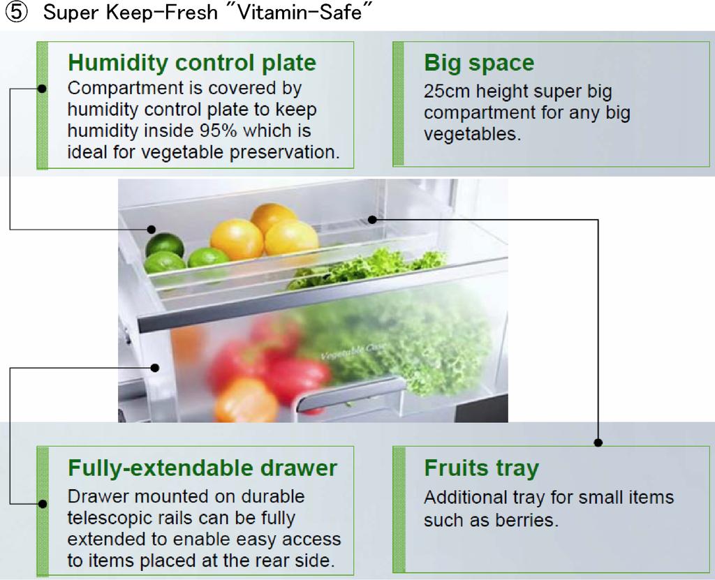
9 Super Keep-Fresh Vitamin-Safe 9

10 10
11 11

12 Super Hygienic 12


13 4.2. Functions

14
15 5 Technical Descriptions 5.1. Temperature control for each compartment FC temperature control The compressor is turned on and off detecting the FC temperature. Operation: The setting temperature -25 C to -17 C, 9 levels change Detection: FCC, ATC sensor 1. When power supply is turned on, FC temperature is displayed on the panel PCB by reading FC setting data of microcomputer memories. The data is written in memory area of microcomputer, 5 seconds after FC setting change. After that, FC temperature is controlled by setting FC temperature of the panel PCB. The FC setting data is memorized, though the power supply of this product is turned off. The setting temperature is fixed, after the time to have set temperature change passed more than 5 seconds. 2. The setting temperature The temperature, when it set on -21 C The OFF/ON temperature value corresponding to each ATC temperature is as shown in the next table. ATC correction temperature Turning off temperature (OFF temperature) Turning on temperature (ON temperature) 34 C or above C C 11 C to 33 C (-23.5)+ {(-23.5)-(-24.0)} (-15.6)+ {(-15.6)-(-16.0)} (ATC correction temperature-10)/ (ATC correction temperature-10)/ (34-10) (34-10) 10 C or below OFF/ON temperature according to FC temperature setting The OFF/ON temperature corresponding to each FC temperature setting is as shown in the following tables. ATC correction temperature Turning off temperature (OFF temperature) Turning on temperature (ON temperature) (-17 C) setting TFOFF + 4 C TFON + 4 C (-18 C) setting TFOFF + 4 C (3 / 4) TFON + 4 C (3 / 4) (-19 C) setting TFOFF + 4 C (2 / 4) TFON + 4 C (2 / 4) (-20 C) setting TFOFF + 4 C (1 / 4) TFON + 4 C (1 / 4) (-21 C) setting TFOFF TFON (-22 C) setting TFOFF C (1 / 4) TFON C (1 / 4) (-23 C) setting TFOFF C (2 / 4) TFON C (2 / 4) (-24 C) setting TFOFF C (3 / 4) TFON C (3 / 4) (-25 C) setting TFOFF C TFON C *: TFOFF and TFON that exist in the following table are considered the temperature calculated by the OFF/ON temperature value at -21 C setting PC temperature control The compressor and 3 way valve are turned on and off detecting the PC temperature. Operation: The setting temperature 1 C to 7 C, 7 levels change Detection: PCC, ATC sensor 1. When power supply is turned on, PC temperature is displayed on the panel PCB by reading PC setting data of microcomputer memories. The data is written in memory area of microcomputer, 5 seconds after PC setting change. After that, PC temperature is controlled by setting PC temperature of the panel PCB. The PC setting data is memorized though the power supply of this appliance is turned off. 15
16 2. The setting temperature The temperature, when it set on 4 C. The OFF/ON temperature value corresponding to each ATC temperature is as shown in the next table. ATC correction temperature Turning off temperature (OFF temperature) Turning on temperature (ON temperature) 34 C or above 8.5 C 10.2 C 11 C to 33 C ( ) ( ) (ATC correction temperature - 10)/ (ATC correction temperature-10)/ (34-10) (34-10) 10 C or below OFF/ON temperature according to PC temperature setting The OFF/ON temperature corresponding to each PC temperature setting is as shown in the following tables. Moreover TPOFF and TPON that exist in the following table are considered the temperature calculated by the OFF/ON temperature value at 4 C setting. ATC correction temperature Turning off temperature (OFF temperature) Turning on temperature (ON temperature) (7 C) setting TPOFF C TPON C (6 C) setting TFOFF C (2 / 3) TPON C (2 / 3) (5 C) setting TFOFF C (1 / 3) TPON C (1 / 3) (4 C) setting TPOFF TPON (3 C) setting TPOFF C (1 / 3) TPON C (1 / 3) (2 C) setting TPOFF C (2 / 3) TPON C (2 / 3) (1 C) setting TPOFF C TPON C *: TPOFF and TPON that exist in the following table are considered the temperature calculated by the OFF/ON temperature value at 4 C setting VC temperature control The single damper motor is turned on and off detecting the VC temperature.driving time. Operation: The setting temperature 5 C to 0 C, 6 levels change Detection: SCC, ATC sensor 1. When power supply is turned on, VC temperature is displayed on the panel PCB by reading VC setting data of microcomputer memories. The data is written in memory area of microcomputer, 5 seconds after VC setting change. 2. According to input of SCC temperature variation, the single damper motor is actuated (normal rotation/reversion). Then the motor is stopped on number of step that set previously. 3. When power supply is turned on, necessarily for getting rid of condition of half opened damper flap, it is closed by 1,850 steps reversion of the single damper motor. 4. After the motor stopped, if there is no variation of input temperature for 60 minutes, the motor is actuated forcibly. When damper flap is opened, it is closed forcibly(1,850 steps reversion). When it is closed, it is opened forcibly (1,850 steps normal rotation). After that, according to the condition of input temperature, the single damper motor is actuated. 5. The damper flap is closed forcibly, during turning on electricity on the heater, during waiting condition after defrosting, during delay of FC fan after defrosting. 6. During compressor stopping, damper flap is closed. 7. The single damper motor wait for 1 second, after its output is stopped. 8. VC temperature adjustment According to VC temperature setting, the single damper flap is opened and closed. 16
17 5.2. FC Defrost Control Cumulating the compressor running time of certain period or time after defrosting according to room temperature and ATC temperature, defrosting cycle starts. Cumulating time for defrosting 4 hours Initially started Cumulating compressor running 8 hours When room and ATC temp. is 25 C or above time 12 hours When room temp. is 19 C or above Cumulating time 28 hours When room temp. is 18 C or below after defrosting Maximum defrosting time is 60 minutes Way Valve Control Cooling Mode Change Control is controlled by detected temperature of PEC, FCC, PCC, SCC Operation condition of 3 Way Valve 1. In case PEC sensor temperature is 4 C or above PEC sensor temperature is Turning on temperature (ON temperature) or above PC cooling mode PEC sensor temperature is Turning off temperature (OFF temperature) or below FC cooling mode 2. In case PEC sensor temperature is less than 4 C FC Cooling Mode is set. However, PC Cooling Mode is set, until PCC sensor temperature is become OFF temperature during PC Cooling Mode. 3. During FC Cooling Mode FCC sensor temperature is OFF temperature or below Compressor off mode 4. However, during FC Cooling Mode, though FCC sensor temperature is OFF temper below, there is a case not to become Compressor OFF Mode, according to VC setting. 5. However, PC Cooling Mode is forcibly ended when reaching at time PC Cooling Mode below.(forcible OFF Cycle Defrost) When condition of PC Cooling Mode is satisfied as above mentioned, it is shifted to PC Cooling Mode Setting operation: Refrigerant Cycle pattern is changed by 3 Way Valve position Basically 3 Way Valve operation of each Mode as shown below. Basic Mode 3Way Valve Compressor condition PC Cooling Mode PC side open ON FC Cooling Mode FC side open ON Compressor OFF Mode PC side open OFF FC Defrost Mode FC side open OFF During waiting after FC FC side open OFF Defrost During Precool Control FC side open ON Initial Control of 3 Way Valve When power is turned on, Initial Control of 3 Way Valve is done. Initial Control: 3 Way Valve is opened toward PC side (Positive pulse 5 time), then 1 second after that, it is opened toward FC side (Negative pulse 5 time) Evacuation Mode When power is turned on, Initial Control of 3 Way Valve is done. Starting: The valve is opened toward PC side of 3way valve when Freezer set button is pressed on Self Diagnosis Mode*. And P FU characters are displayed on the control panel. Self Diagnosis Mode can be started when Super Freeze button on the control panel is pressed more than 5 seconds. Ending: Press Freezer set button again, then Evacuation Mode is ended and Self Diagnosis Mode appear again. During Evacuation Mode, to press Super Freeze button the Mode is ended. Or 7 minutes after starting the Self Diagnosis Display Control, at the same time Self Diagnosis Mode is ended too. When power is turned on: Forcible OFF Cycle Defrost is started from Defrost stopping. Normal Time: PC Cooling Mode is continuously for 10 hours. PC Cooling Mode is reset at the same time with Time Rest Way Valve Control when power is turned on It is FC Cooling Mode from power turning on to 15 minutes, PC Cooling Mode from 15 minutes to 40 minutes, to be normal 3 Way Valve Control after 40 minutes. 17
18 5.4. Antibacterial deodorant control (Deodorizing fan control, Antibacterial PC-LED control) ON/OFF control of Deodorizing fan Press and hold the Hygiene Plus button for 0.5 second. Hygiene Plus indicator lights up and Antibacterial deodorant control starts. Press and hold the Hygiene Plus button for 0.5 second Hygiene Plus indicator lights off and Antibacterial deodorant control stops. ON/OFF of Deodorizing fan is controlled by ATC sensor, FCC sensor, PCC sensor and PC door open or close Operation control of Deodorizing fan 1. Press and hold the Hygiene Plus button for 0.5 second. First of all, it enters A mode that is rapid deodorization driving, the deodorizing fan drives for 120 minutes continuously. After starting B mode that is normal deodorization driving, the deodorizing fan control starts. AT 10 C or below 11 C to 21 C 22 C to 28 C 29 C or above When compressor ON When PC is cooled ON ON ON ON When FC is cooled ON ON ON ON When Compressor OFF 2. Press and hold the Hygiene Plus button for 0.5 second when antibacterial deodorant control starts. When the antibacterial deodorant control stops (C mode), the deodorizing fan stops. 3. When power supply is turned on. The deodorizing fan stops, even if A, B or C mode, when ATC is 34 C or above and while FCC is 27 C or above. 4. When PC door open. The deodorizing fan stop forcibly even if A, B or C mode, While PC door opens. (To be dewy prevention, frost prevention) Antibacterial PC-LED control 1. Basic operation n A or B mode of the deodorizing fan control, antibacterial PC-LED turn on while the deodorizing fan drives. (If the fan stops, the LED is turned off.) 2. Exceptional control In A or B mode of the deodorizing fan control, antibacterial PC-LED is turned on forcibly while PC door opens Photosynthesis-freshness-improving effect control Input: To press and hold the Vitamin-Safe button for 0.5 second. Output: LED of VC (Green LED, Blue LED) The fan drive for 30 minutes after compressor OFF The fan drive for 10 minutes after compressor OFF The fan OFF The fan OFF Content of processing: Press and hold the Vitamin-Safe button for 0.5 second, Vitamin-Safe indicator lights up and both the blue LED and the green LED blink at the same time. It is operating a photosynthesis-freshness-improving effect control. While operating the control, press and hold the Vitamin-Safe button for 0.5 second, the control stops and Vitamin- Safe indicator lights and LED of VC are turned off. Photosynthesis-freshness-improving effect control Blue LED Green LED While operating the control 40Hz flashing (ON/OFF: at each of 9.1msec) While stop OFF OFF 5.6. FC Fan Control FCDC Fan Motor (FC fan) operation is controlled, to prevent a trip of compressor when initial pull down, for making properly the temperature in the FC and the control of a power consumption increase. Detection: ATC sensor 18
19 Control of starting FC fan motor is rotated of high speed, for 10 seconds after starting. Synchronous control of compressor FC fan is operated, while compressor is operated. FC fan is operated, while FC Cooling Mode. Control of Door Open/Close FC fan is stopped while FC door is opened. FC fan delay control, when FC defrost is stopped When Defrost ends, three minutes pass after compressor works, the FC fan does the forcibly stop for six minutes. Control of FC Fan rotational speed High speed drive: DC 12V Common drive: DC 10V Stop: 0V In case normal control ATC correction temperature is 21 C or below ATC correction temperature is 22 C or above, 28 C or below ATC correction temperature is 29 C or above, 33 C or below PC Cooling Mode FC Cooling Mode PC Cooling Mode FC Cooling Mode PC Cooling Mode FC Cooling Mode Common Common Low speed High speed Low speed High speed 5.7. Compressor Rotational Speed Control For securing the amount of cooling according to the overload at a high ambient temperature, the rotational speed of the compressor is changed by difference of temperature between FCC and FC Control setting, PCC and PC Control setting. Detection : FCC, PCC, ATC sensor Normal time The judgment of compressor ON: FCC is ON temperature or above or PC and FC Cooling Mode The judgment of compressor OFF: While FC is cooling FCC is OFF temperature OFF or above While power is turning on of FC Defrost Heater, While waiting of compressor start The use rotational speed The rotational speed of compressor is changed by deference between FCC temperature standard value (ON temperature) and FCC temperature, PCC temperature standard value and PCC temperature. The rotational speed according to ambient temperature is as follows, it doesn't drive in other rotational speeds. The use rotational speed Setting rotational speed of compressor Rotational speed R1 R2 R3 R4 R5 Setting value r/s The use rotational speed according to ambient temperature is as follows Ambient temperature Rotational speed of compressor A 21 C or below 25/39/43 r/s B 22 C to 28 C 25/39/43/59 r/s C 29 C to 33 C 43/59/71 r/s D 34 C or above 59/71 r/s In case Super Freeze Ambient temperature is 21 C or below Ambient temperature is 22 C or above, 33 C or below Ambient temperature is 34 C or above 43 / 59 r/s 59 / 71 r/s 59 / 71 r/s 19
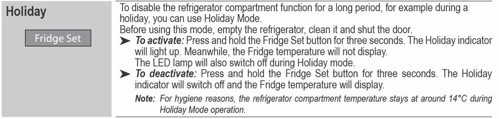
20 *Notes In case of A and B, the rotational speed is 43r/s from when power is turning on to compressor OFF. However in case of setting of Super Freeze, the rotational speed of Super Freeze take precedence 5.8. Compressor starting control The compressor is not start while waiting timer is operating. And when power is turned on, compressor staring control is not available. After power turning on After FC Defrost stopping (Improvement of start after defrost) After compressor stopping (Prevention of trip when re-starting) Sequence protection Under voltage protection, DIP-IPM protection 0 minute 3 minutes 10 minutes 10 minutes 10 minutes 5.9. Holiday Control To activate: Press and hold the Fridge Set button for 3 seconds. The Fridge temperature is not displayed while Holiday indicator lights up. The LED lamp will not light up during Holiday mode To deactivate: Press and hold the Fridge Set button for 3 seconds. The Fridge temperature is displayed while Holiday indicator lights off. For the OFF/ON temperature of PC 4 setting, corresponding to each ATC correction temperature. PC temperature is adjusted to add 10 C to each OFF or ON temperature. The acceptance of the refrigeration setting by to press Fridge Set button becomes to be invalid during Holiday Control. The room lamp is turned off when PC Door is opened, during Holiday Control. 20

21 6 Location of Controls and Components 6.1. Display and Control Panel 21
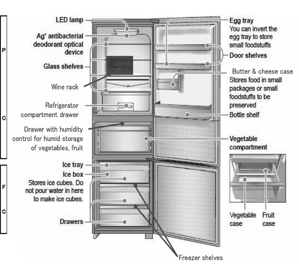
22 6.2. Components 22

23 7 Installation Instructions 7.1. Installation Instructions 23

24 7.2. Getting started 24
25 25
) After Defrost starting, it is operated normally of Defrost Control. 8.2.")
26 8 Test Control 8.1. Compulsion Defrost Defrost start forcibly, to make TEST TERMINAL 1 and 2 touch for an instant. (See the following picture of PCB (CONTROL)) After Defrost starting, it is operated normally of Defrost Control Compulsion FC Fan start Compulsion FC Fan drive high speed, to be making short-circuit* of TEST TERMINAL 1 and 3. (See the following picture of PCB (CONTROL)) Compulsion FC Fan drive is ended when the short-circuit is released To change the rotation speed of compressor Starting: To be making short-circuit of TEST0 POINT and GND on the PCB (CONTROL). (See the following picture of PCB (CONTROL)) To press 1 time "Super Freeze" : Value of compressor rotation 25 r/s To press 2 times "Super Freeze" :Value of compressor rotation 39 r/s To press 3 times "Super Freeze" :Value of compressor rotation 43 r/s To press 4 times "Super Freeze" :Value of compressor rotation 59 r/s To press 5 times "Super Freeze" :Value of compressor rotation 71 r/s Ending: To release short-circuit of TEST0 POINT and GND Cut of waiting compressor start Compressor start waiting is not operated, when to be making short-circuit* of TEST2 POINT and GND. It is ended when the short-circuit is released. (See the following picture of PCB (CONTROL)) *: Use short-circuit tool Picture of PCB (CONTROL) 26
27 9 Service Mode 9.1. Self Diagnosis Display Mode Self Diagnosis Function is available on the model and Self Diagnosis Mode is displayed on the display and control panel at the front center of PC Door, when trouble and/or failure happens. A : How to start When Super Freeze button on the control panel is pressed more than 5 seconds, Self Diagnosis display mode appeared. The sign is displayed at center of Fridge temperature display area and Freezer area. And when there are more than two signs, those are appeared continuously every 1second. Then finally - is displayed at Fridge area and -- is displayed at Freezer area. When there is not any trouble/failure, - is displayed at Fridge temperature area and -- is displayed at Freezer area. B : How to end Self Diagnosis mode ends When Super Freeze button is pressed for less than 1 second while Self Diagnosis display mode Trouble / Failure history display mode A : How to start Trouble / Failure sign is displayed when Super Freeze button is pressed for more than 1 second while Self Diagnosis display mode. When the sign is displayed, - is displayed at left side of Freezer temperature display area. For example: When there is a trouble of FC temperature sensor. Fridge temperature display area: H, Freezer area: - 01 When there is not trouble/failure history. Fridge temperature display area: H, Freezer area: --- B : How to end Trouble / failure history display mode ends when "Super Freeze button" is pressed for more than 1 second while that mode. Or 7 minutes after starting the Self Diagnosis Display mode, Self Diagnosis Mode is ended automatically. 27
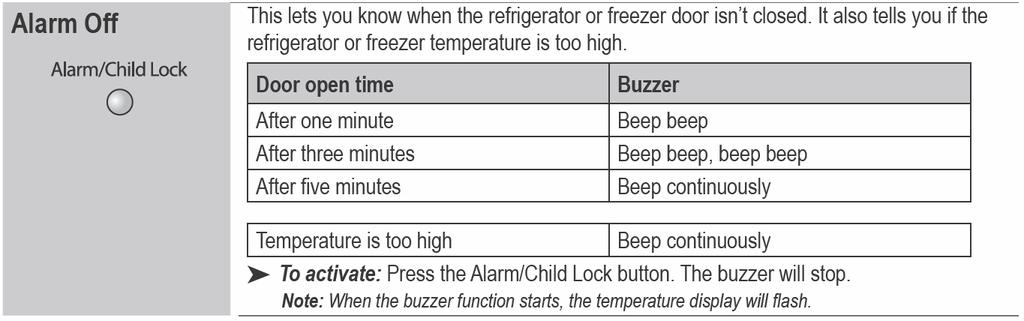
28 9.3. The display sign list of self diagnosis code. Signal Symptom Check point Condition Display release U10 Warning that door is kept open. 1.Close compartment door completely 2.Door SW PCB The sign is displayed when PC / FC Close the door, Adjust door is kept open for more than 1 the door, Replace the 3. Door aliment 4.Control PCB minute. door SW PCB, Replace control PCB H01 H02 H05 FC temperature sensor circuit has trouble. PC temperature sensor circuit has trouble. Sensor DEFROST circuit has trouble. 1.SensorFC 2.Sensor FC circuit 3.Control PCB 1.Sensor PC 2.Sensor PC sircuit 3.Control PCB 1.Sensor DEFROST 2.Sensor DEFROST circuit 3.Control PCB 4.Thermal fuse* H07 Sensor ATC circuit has trouble. 1.Sensor ATC 2.Sensor ATC circuit 3.Control PCB H10 SSC, Vegetable compartment 1.Sensor SC circuit sensor circuit has trouble. 2.Control PCB H12 PEC sensor circuit has trouble. 1.Sensor PEC 2.Sensor PEC circuit 3.Control PCB H31 H35 H36 FC defrost heater circuit has trouble. Refrigerating unit has trouble. (3 way valve / Gas leakage at high pressure side / Poor compression) Refrigerating unit has trouble. (Gas leakage at low pressure side) IPM & Compressor Protection Control has trouble. Under voltage protection has trouble. 1.FC defrost heater 2.Thermal fuse 3.Control PCB 1.3 way valve 2.Gas leakage at high pressure side 3.Poor compression 1.Gas leakage at low pressure side H40 1.Control PCB 2.Compressor(Lock) H41 1.Power supply voltage 2.Control PCB H50 Communication error 1.Control PCB 2.Operation PCB 3.Wire circuit between control PCB and operation PCB Open or short Open or short Open or short (Note) When DFC is opened, thermal fuse is blown because of too long defrosting time. Open or short Open or short Open or short Replace parts Replace parts Replace parts Replace parts Replace parts Sensor PEC can not replace Temperature of defrost Sensor Replace parts does not reach cut-off temperature. Even if compressor runs, FC temperature and DEF temperature Replace parts would not be below 0 C continuously. H40 and H36 display repeatedly. Replace parts Over current flow into IPM for a long time. Low voltage add to unit for a long time. Micro- computer can not read or write the data. H51 Control PCB has trouble. 1.Control PCB Emulation initialization judgment error when power supply is turned on. H52 Control PCB has trouble.(voltage to compressor) 1.Control PCB Inverter voltage is too high. Inverter voltage is too low. Replace parts Replace parts Replace parts Replace parts Replace parts 28
29 10 Troubleshooting Guide FC and PC not cooling at all. [Compressor does not run.] 29
30 10.2. PC is not cooling or poor cooling. [FC cooling condition is normal.] 30
31 10.3. FC is poor cooling. [Compressor run.] 31
32 10.4. VC is poor cooling or excessive cooling. 32
33 11 Disassembly and Assembly Instructions Disassembly of PC (Refrigerator Compartment) Box Fan, Ag Filter, Low Temp Deodorizer 1. Remove Cover Fan & Ag a. Take Tray PC A ssy out. b. Remove two screws on Cover Fan & Ag by a screwdriver (+). c. Grab the rear of Cover Fan & Ag, and remove while pulling it down. FIGURE OF HOLDER FAN & AG THE POINT OF REPLACEMENT OF BOX FAN A SSY Unhook the hook of upper side of Box Fan A'ssy from reverse side. Then pull Box Fan A'ssy out. THE POINT OF REPLACEMENT OF AG FILTER Pull Ag Filter out from hooks of Holder Fan & Ag. 2. Remove Holder Fan & Ag a. Remove the screw of upper side of Box Fan. b. Press the hook toward you, and remove Holder Fan & Ag. c. Take the connector out and pull it out while pressing hook. THE POINT OF REPLACEMENT OF LOW TEMP DEODOR- IZER Unhook the hook of Low Temp Deodorizer from reverse side of Holder Fan & Ag. Then pull Low Temp Deodorizer out. 33
34 PCB (LED) 1. Unhook hooks of left and right side, and pull PCB (LED) in a direction below. Pull the connector out, and remove PCB (LED) SENSOR PC 1. Take Tray PC A'ssy out. 2. Rotate Cover Sensor anti-clockwise, and remove it. 3. Pull Sensor PC from inside Inner Liner like the figure. NOTES Be careful not to break PCB (LED) when it is removed and installed PCB (DEO) 1. Remove the screw that is fixation of Cover LED. Then remove Cover LED out 2. (2)Take PCB (DEO) out from reverse side two Hooks of Cover LED. 3. Pull the connector out while pressing the hook. IN CASE REPLACEMENT SENSOR PC 1. Cut the wire at near Sensor PC. 2. Connect new Sensor PC and wire by Scotch Lock. 3. (3)Install Cover Sensor to rotate clockwise. THE POINT OF WORK 1. Insert deeply each wire one by one in Scotch Lock. The Scotch Lock is the structure that can connect unstripped wires. Then it is unnecessary to use wire stripper. (When you connect wires that was peeled off film, it is easy to come off them.) 2. The lid (color painted) of the Scotch Lock is crimped with pliers. Then the lid height become in the same of the body height of the Scotch Lock. When you crimp the Scotch Lock with pliers, please work while holding these wires to the Scotch Lock side so that these wires should not come off. NOTES Be careful not to break PCB (DEO) when it is removed and installed. 34
35 3. Check good operation or not those parts after the work. CAUTION Be careful not to be bite the wires by Cover Sensor, when store the wires and the Scotch Lock in Cover Sensor Disassembly of VC (Vegetable Compartment) PCB (VC) 1. Remove Crisper A'ssy Pull Crisper Case, take it out from each two portions of Rail VC right and left. -You can see the figure below ( (1)) DUCT VC 1. Remove Crisper A'ssy Pull Crisper Case, take it out from each two portions of Rail VC right and left. -You can see the figure ( (1)). 2. Remove Duct VC A ssy toward you while pulling the hook of upper side. 2. Remove the screw that is fixation of Cover LED on upper side of VC. Then remove Cover LED. 3. (3)Remove PCB (VC) while pressing left and right hooks of reverse side of Cover LED. 4. (4)Pull the connector out while pressing the hook. 3. Remove Duct VC. Remove the connector of Damper Thermostat, then take Duct VC out. Take out INS Duct VCT and INS Duct VCB form four hooks of Duct VC. Tear off Foam tape, removes Sensor SC from fixation part of INS Duct VCT. NOTES Be careful not to break PCB (VC) when it is removed and installed CRISPER A SSY 1. Remove Crisper A'ssy. Pull Crisper Case, take it out from each two portions of Rail VC right and left. 35
36 SENSOR SC A SSY AND DAMPER THERMOSTAT 1. Separate INS Duct VCT and INS Duct VCB Tear off crepe tape, separate INS Duct VCT and INS Duct VCB Disassembly of CASE SW A SSY CASE SW A SSY 1. Insert screwdriver (-) in a gap of the triangle mark portion of Case SW A'ssy then pry off Case SW A'ssy. 2. Remove each parts The point of replacement of Damper Thermostat. a. Take Damper Thermostat out from INS Duct, pull the connector out. b. Replace Damper Thermostat. The point of replacement of Sensor SC A ssy. a. Take Damper Thermostat out from INS Duct, pull the connector out. b. Replace Sensor SC A ssy. NOTES Be careful not to make a scratch by screwdriver (-) to the paint work of Center Crossrail. Please put a tape on the part where a screwdriver (-) touch to prevent paintwork in the Center Crossrail being damaged. 2. Remove two connectors. Do not pull wire so strongly to remove the connector. The connector can be taken out while pressing the hook. NOTES 1. Put heat insulator on around Damper Thermostat as before, after connect the connector with it 2. Install Damper Thermostat securely. It might become cause of leakage of cooling air. 3. Put crepe tape on joint parts, after assembly INS Duct VCT and INS Duct VCB. 4. Fix Sensor SC A ssy to the hook of IND Duct VCT as before. NOTES The connector is classified by the color. Connect those connectors as before so as not to make mistake. Be careful not to bite wires between Case SW A'ssy and Center Crossrail when you install Case SW A ssy. 36
37 11.4. Disassembly of FC (Freezer Compartment) SENSOR FC 1. Take Case FCT A ssy and Case FCB A ssy out of FC. 2. Take Glass Tray FCT and Glass Tray FCB out. a. Remove the screws that are fixation of Holder Glass. (Each of two FC right and left) b. Remove Holder Glass and pull Glass Tray FCT and Glass Tray FCB out. 4. Cut the wire at near the Sensor FC. The figure is left side view also there are Holder Glass R in the right side. 3. Take Cover Connector FC out. a. Remove the screw that is fixation of Cover Connector FC on the left of upper side of FC. 5. Connect new Sensor FC and wires by Scotch Lock. NOTES ON INSTALLATION Hook Sensor FC to the hook of Cover Connector FC as before, store Sensor FC and Scotch Lock reverse side of Cover Connector FC. Connect the connector of Fan Motor FC securely, store the connector to the hook reverse side as before. Insert Cover Connector FC in upper side of FC as before, screw the screws that are fixation of it. b. Pull Cover Connector FC toward you, unhook the Hooks(4 portions). c. Remove sensor FC from the hook of reverse side of Cover Connector FC, pull out the connector for Fan Motor FC. THE POINT OF WORK 1. Insert deeply each wire one by one in Scotch Lock. The Scotch Lock is the structure that can connect unstripped wires. Then it is unnecessary to use wire stripper. (When you connect wires that was peeled off film, it is easy to come off them.) 37
38 2. The lid (color painted) of the Scotch Lock is crimped with pliers. Then the lid height become in the same of the body height of the Scotch Lock When you crimp the Scotch Lock with pliers, please work while holding these wires to the Scotch Lock side so that these wires should not come off. b. Pull Cover Connector FC toward you, unhook the Hooks(4 portions). c. Remove sensor FC from the hook of reverse side of Cover Connector FC, pull out the connector for Fan Motor FC. 3. Check good operation or not those parts after the work. CAUTION Be careful not to bite the wires by Cover Sensor, when store the wires and the Scotch lock in Cover Sensor COVER COIL FC 1. Take Case FCT Assy and Case FCB A ssy out of FC. 2. Take Glass Tray FCT and Glass Tray FCB out. a. Remove the screws that are fixation of Holder Glass FC. (Each of two FC right and left) b. Remove Holder Glass FC and pull Glass Tray FCT and Glass Tray FCB out. 4. Remove Cover Coil FC A ssy a. Remove three screws in front of Cover Coil FC A ssy. b. Remove Cover Coil FC A ssy while pulling bottom side. The figure is left side view also there are Holder Glass R in the right side. 3. Take Cover Connector FC out a. Remove the screw that is fixation of Cover Connector FC on the left of upper side of FC. 38

39 The figure of after Cover Coil FC A ssy is removed SENSOR DEFROST, TEMPER- ATURE FUSE A SSY RADIANT HEATER 1. SENSOR DEFROST a. Remove Holder Def Sensor that is installing upper side of Accumulator. b. Remove Sensor Defrost from Holder Def Sensor. d. Remove the connector of Sensor Defrost, then replace new Sensor Defrost. NOTES ON INSTALLATION OF SENSOR DEFROST Install Sensor Defrost in Holder Def Sensor, then install Holder Def Sensor in upper side of Accumulator as before. Tighten Bag Joint that is put in the connector of Sensor Defrost with other connectors by Cable Tie as before. Store Bag Joint to the place as before. c. Pull Bag Joint from storage part of depths of upper side of FC. Cut Cable Tie of Bag Joint, then take out wires and connectors inside it. 2. TEMP FUSE A SSY a. Cut Cable Tie that is fixation of Temp Fuse A ssy in side of Evaporator. 39


40 b. Pull Bag Joint from storage part of depths of upper side of FC. Cut Cable Tie of Bag Joint, then take Bag Joint. c. Remove the connector of Temperature Fuse A ssy, then replace new Temp Fuse A ssy. NOTES ON INSTALLATION Tighten Temp Fuse A ssy by Cable Tie to pipe of Evaporator. Tighten Bag Joint that is put in the connector of Temp Fuse A ssy with other connectors by Cable Tie as before. Store Bag Joint to the place as before. c. Unhook 10 hooks, then remove the wires of Defrost Heater A ssy. d. Pull Bag Joint from storage part of depths of upper side of FC. Cut Cable Tie of Bag Joint, then take Bag Joint. e. Pull out two connectors of Radiant Heater A ssy, then replace new Defrost Heater A ssy. 3. DEFROST HEATER A SSY a. Remove Defrost Heater A ssy forward from right and left side hooks that are fixation of Defrost Heater A ssy while pressing up hooks. NOTES ON INSTALLATION Install Heater Cover in rubber cap securely. Arrange the lead wires, hook them to the wire hooks. Tighten Bag Joint that is put in the connector of Defrost Heater A ssy with other connectors by Cable Tie as before. Store Bag Joint to the place as before. b. Remove Heater Cover of upper side of Defrost Heater A ssy. NOTES ON INSTALLATION OF COVER COIL FC A SSY Install Cover Coil FC A ssy in upper side of depths of FC, then fix it by three screws. It might be cause of getting frost, in case of imperfect installation of Cover Coil FC A ssy. 40
41 FAN MOTOR FC ASSY 1. Take Case FCT A ssy and Case FCB A ssy out of FC. 2. Take Glass Tray FCT and Glass Tray FCB out. a. Remove the screws that are fixation of Holder Glass. (Each of two FC right and left) b. Remove Holder Glass and pull Glass Tray FCT and Glass Tray FCB out. 4. Remove Cover Coil FC A ssy a. Remove three screws in front of Cover Coil FC A ssy. b. Remove Cover Coil FC while pulling bottom side. The figure is left side view also there are Holder Glass R in the right side. 3. Take Cover Connector FC out a. Remove the screw that is fixation of Cover Connector FC on the left of upper side of FC. 5. Take Fan Motor FC A ssy out a. Separate INS Cover Coil from two hooks of right and left side of Coil Cover FC. b. Take Fan Motor FC A ssy out from INS Cover Coil to press toward the arrow like the figure. b. Pull Cover Connector FC toward you, unhook the Hooks(4 portions). c. Remove sensor FC from the hook of reverse side of Cover Connector FC, pull out the connector for Fan Motor FC A ssy. NOTES ON INSTALLATION You can see the label of Fan Motor FC form this side 41

42 when you install it in INS Cover Coil. Install Fan Motor FC A ssy in INS Cover Coil. It might be cause vibration, abnormal sound, in case of imperfect installation of Fan Motor FC A ssy. Tighten Bag Joint that is put in the connector of Fan Motor FC A ssy with other connectors by Cable Tie as before. Insert Cover Connector FC in upper side of FC as before, screw the screw that is fixation of it. 3. Remove the screw that is fixation of PCB (Panel), and unhook six hooks of PCB (Panel). Then take PCB (Panel) out from Button Control. NOTES ON INSTALLATION OF COVER COIL FC A SSY Install Cover Coil FC A ssy in upper side of depths of FC, then fix it by three screws. It might be cause of getting frost, in case of imperfect installation of Cover Coil FC A ssy Disassembly of PCB (Panel), Button Control Assy PCB (Panel), Out Door Control A SSY 1. Insert screwdriver (-) into the gap between Out Door Control A ssy and Door A ssy PC. Then pry off Out Door Control A ssy. NOTICE Be careful not to break PCB (Panel) when it is removed and installed. It might become cause of defective operation Disassembly of PCB Control, PCB Inverter PCB Control, PCB Inverter 1. Remove + screw and Torx screw, and remove the Cover PCB Assy. 2. Disconnect the connectors, and unscrew the screw of right side of each PCB. Remove each PCB, while unhooking the hooks. NOTICE Please put a tape on the part where a screwdriver (-) touch, to prevent paintwork in the Door A ssy PC being damaged. 2. Pull the connector of PCB (Panel) out while pressing the hook, and take it out from Door A ssy PC. CAUTION Be careful not to touch directly electric parts on the PCB when you remove and install each PCB. 42


. Remove Protector Cover. b.")

43 11.7. Disassembly of Compressor Room Pan Water EVA., Motor Protector, Cluster Block 1. Pan Water EVA a. Pull Power Supply Code out. b. Remove the six screws on Cover Panel Compressor. c. Pull and remove Cover Panel Compressor Assy toward you from upper side. d. Pull Pan Water EVA. toward you while pressing it up. 2. Motor Protector a. Insert a screwdriver (-) into the gap between Protector Cover and Compressor like the figure. Pry off Protector Cover in a screwdriver (-). Remove Protector Cover. b. Take Motor Protector out from inside Protector Cover. 3. Cluster Block a. Pull Cluster Block out from Compressor like the figure. NOTICE When you install Cover Panel Compressor Assy, set the holes of the six screws firstly. Secondly adjust Cover PCB's position, and screw the six screws. NOTICE Be careful not to twist when you pull Cluster Block out or install. 43
44 11.8. The Door Setting Exchange Work Manual This appliance is setting right side opening door when it is shipped from the factory. However you can change the door setting to left side opening to exchange those parts as below. You can exchange those parts to refer to the work manual below. TO PREPARE AND TO CONFIRM FOR THE WORK 1. Confirm the parts Confirm whether there are those parts below or not. (Bundled Parts) A'ssy PC. Remove trays and shelves of reverse side of Door A'ssy PC, to prevent the trays and shelves from cracking and breaking. (When there is some foods on reverse side of the door, it is necessary to take foods out. When you do not take foods out, the floor might be made dirty with the dropping foods.) 3. Unplug the refrigerator Unplug the refrigerator before work for your safety. NOTICE After the power is turned off, the temperature of each compartments are risen. There is turn ned off, the temperature of each compartments are risen. THE POINTS OF WORK Remove Door A ssy PC Remove Cover Hinge Top R a. Insert screwdriver (-) to a gap of Button plate control, and pry it off. b. Remove two screws that are fixation of Cover Hinge Top R. c. Pry off three Hooks (triangle mark part) of Cover Hinge Top R by screwdriver (-), then remove Cover Hinge Top R. 2. Remove Cover Table L. Remove Cover Table L in the same way above. (The matter of importance) When you install an important hinge with the torque restriction, tighten by a torque wrench after it fixes with a plus screwdriver temporarily. There is a possibility of damaging screw when strongly tightening too much. 3. Remove Hinge Top R a. Pull the connector from connector storage part, then pull the connector out while pressing the hook to upper side. b. Remove Three screws that are fixation of Hinge Top R, pull the connector out through the hole of Hinge Top R. c. Remove Three screws that are fixation of Hinge Top L. 2. Remove trays and shelves of reverse side of Door 44
45 3. Remove Hinge Bottom R Remove two screws that are fixation of Hinge Bottom R. Remove Hinge Bottom R Exchange Stopper Door & Latch Door 1. Exchange Stopper Door & Latch Door of Door A ssy FC a. Turn the Door A ssy FC upside down first. Remove the two screws that are fixation of Latch Door R of under side of Door A'ssy FC, then remove Stopper Door and Latch Door R. (Stopper Door and Latch Door R are disused.) b. Put Latch Door L upon Stopper Door L, fix securely on left side of bottom of Door A ssy FC. by the two screws that were removed above (1). CAUTION Be careful not to forcibly bend when the connector is through the hole of Hinge Top R. Because it might be cause to wire cut or connector damage. Please do removing and installation work of Hinge Top R by two persons, the person who has Hinge Top R and the person who has Door A'ssy PC, in total. Because it might be cause of dropping accident of Door A'ssy PC. 4. Remove Door A ssy PC from Hinge Center R while lifting the door Remove Door A SSY FC 1. Remove Hinge Center R a. Open Door A'ssy FC, and remove two screw that are fixation of Hinge Center R. b. Remove Hinge Center R and Shim Hinge FCT. c. Remove Cap Hinge Pin FCT. 2. Exchange Stopper Door & Latch Door of Door A ssy PC Do in the same work as before Exchange Stopper Door & Latch Door of Door A ssy FC. 2. Remove Door A ssy FC from Hinge Bottom R while lifting the door 45
46 Install Door A'ssy FC 1. Install Hinge Bottom L a. Tear off the Label Bottom that is sealed at the position of Hinge Bottom L of bottom and left side of the appliance. b. Seal the Label Bottom at the setting position of Hinge Bottom R of bottom and right side of the appliance. c. Pull out the Cap Hinge that is inserted in the setting hole of Hinge Center L of middle height and left side of the appliance. d. Insert the Cap Hinge in the setting hole of the Hinge Center R of middle height and right side of the appliance. of Hinge Bottom L, and insert Door A ssy FC into Hinge Bottom L. e. Apply the grease of bundled parts on around of Shim Hinge FCT on Door A ssy FC. f. Shim Hinge FCT and Hinge Center L put together, and screw Pin Hinge Center on Hinge Center L. (Torque of screw: 6 ± 2 N m) NOTES Wipe a grease of around the area with a new or cleaned cloth before installing Label Bottom and the Cap Hinge, because grease might remain. Wipe a grease of around gasket touching face of body and the gasket with a new or cleaned cloth. e. Install Hinge Bottom L by bundled screws that are fixation it. (Torque of screw : 6 ± 2 N m) CAUTION Pin Hinge Center is screwed on Hinge Center L to use a torque wrench. Two screws of Hinge Center L are screwed to use a torque wrench. CAUTION Screw these screws up Hinge Center L and hinge Bottom L securely, there must not be them loosening. And screw Pin Hinge Center L up Hinge Center L securely too, there must not be it loosening. Because it might become cause of an accident of falling door and there is a possibility that an unexpected serious accident occurs. CAUTION These screws of Hinge Bottom L are needed to screw to use a torque wrench. 2. Install Door A'ssy FC a. Install Shim Hinge FCT that was removed before (see )- in the hole of upper and left side of Door A ssy FC. b. Install Cap Hinge Pin FCT in upper and right side of Door A ssy FC. c. (3)First open Door A ssy FC, install Hinge Center L in the Refrigerator by bundled screws for fixation. (Torque of screw: 6 ± 2 N m) d. Apply the grease of bundled parts on around pin 46
47 Install Door A'ssy PC Remove the connector that connect with Door A'ssy PC a. Remove the screw that is fixation of Cover Cap Door PCT L. b. Insert screwdriver (-) into a gap of Cover Cap Door PCT L, and pry off hooks (2 portions). Remove Cover Cap Door PCT L. c. Insert screwdriver (-) into a gap of Cover Harness PCT, and pry off hooks (2 portions). Remove Cover Harness PCT. 3. Install Hinge Top L a. Through the connector to the hole of Hinge Top L. d. Pull out the connector that is connected with Door A'ssy PC, and remove the connector while pressing toward upper side. CAUTION Be careful not to forcibly bend when the connector is through the hole of Hinge Top L. Because it might be cause to wire cut and connector damage. b. Apply the grease on the tongue of Hinge Top L and insert it into Door A ssy PC. c. Three screws that are fixation of Hinge Top L are temporarily screwed. d. Adjust Door A ssy PC perpendicularly and horizontally in the same of Door A ssy FC. e. Store the connector in Cover Harness PCT, install Cover Harness PCT in Door A ssy PC as before. 2. Install Door A'ssy PC a. Apply the grease on around Pin Hinge Center b. Lift Door A ssy PC, and insert left bottom of Door A ssy PC into Hinge Center L. 47
48 e. Install and adjust Hinge Top L on the top table, screw three screws that are fixation of it to use a torque wrench. (Torque of screw: 6 ± 2 N m) b. Open Door A ssy PC, put Cover Hinge Top L on this side of the Hinge Top L. c. Insert hooks (2 portions) of out side to under Hinge Top L, and hook the hooks of inside. (Do not forcibly press Cover Hinge Top L. Because it might cause of damage of hooks.) d. Screw the screws that are fixation of Cover Hinge Top L. e. Install Button Plate Control. CAUTION Fix Hinge Top L securely by three screws for fixaiton. In case of not enough fixation, it might become cause of an accident of dropping the Door A'ssy PC. Three screws of Hinge Top L are screwed to use a torque wrench. 4. Install Cover Hinge Top L a. Connect the connector of Door A'ssy PC, fix the connector into storage part. 5. Make the connector of Door A ssy PC waterproof Tighten Bag Joint that is put in the connector of upper and right side of Door A ssy PC by Cable Tie. CAUTION The wire harness is arranged not to touch Hinge Top L, not to bend it. 6. Install Cover Cap Door PCT R and Cover Table R a. Three screws that were removed before (see C) are screwed on the holes of screws that are fixation of Hinge Top R. b. Install Cover Table R in Hooks of Top Table. c. Store the connector of right side of Door A ssy PC in Cover Cap Door PCT R. d. Store Bag Joint in Cover Cap Door PCT R, put and install hook of Cover Cap Door PCT R into Door A ssy PC. e. Screw Cover Cap Door PCT R. 48

49 3. Does the Door open and close smoothly? (Did you apply the grease of bundled parts around driving parts of hinge?) 4. (4)Is there any sound when the Door open and close? 5. Does some character appear on the control display, after turn it on? 6. Can you set a temperature by pressing any button? When there is not any trouble above, you install some trays and shelves in reverse side of Door A'ssy PC as before Final check 1. Is there a gap between the body and the Door A'ssy PC, when the door is closed? (If there is a gap, it might become cause of leakage of cooling air.) NOTES Wipe a grease off with a new or cleaned cloth, after Stopper Door R and Latch Door R are removed. Stopper Door R and Latch Door R, Hinge Top R etc. that are removed are needed to return to the Door Setting. Please keep them carefully. Confirm whether there is a gap to put a sheet of paper between the body and gasket like the figure. 2. Is not Gasket Door slid smoothly, nor be bitten it nor come it off? If there is something wrong like above, apply the grease of bundled parts inside of Gasket Door. 49


50 12 Maintenance Automatic Defrosting Removing and attaching shelves 50

51 12.3. Care and cleaning instructions 51
52 52
53 13 Dimensions Outside (NR-B30FX1, NR-B30FG1) 53
")
54 13.2. Inside (NR-B30FX1) 54
")
55 13.3. Inside (NR-B30FG1) 55
TABLE OF CONTENTS REFRIGERATOR-FREEZER. Model No. NR-BN34FX1 Model No. NR-BN34FW1
 Order Number GORR1405001CE REFRIGERATOR-FREEZER Model No. NR-BN34FX1 Model No. NR-BN34FW1 Product-Color X:Stainless W:White Destination E(Europe Continental) B(U.K.) TABLE OF CONTENTS PAGE 1 Safety Precautions-----------------------------------------------
Micro-computer control (FC:FCC sensor) / Full-automatic direct control (PC:Damper thermo.)
 / Full-automatic direct control (PC:Damper thermo.)") 1.1 Specifications MODEL SPECIFICTIONS Storage Capacity Gross Capacity Outside dimensions Width Depth Height Net weight Type Temperature control Defrosting Defrost water disposal Exterior finish Inner
1.1 Specifications MODEL SPECIFICTIONS Storage Capacity Gross Capacity Outside dimensions Width Depth Height Net weight Type Temperature control Defrosting Defrost water disposal Exterior finish Inner
Model No. NR-BU303 Series
 RBD / PGF / GULF Operating Instructions Refrigerator For Household Use Model No. NR-BU303 Series NR-BU343 Series Contents Safety precautions...2 Installation...4 Parts identification...5 Specification...5
Part 3 Troubleshooting
 Part Troubleshooting What is in this part? This part contains the following chapters: Chapter See page Troubleshooting 2 Error Codes: Hydro-box 7 Error Codes: Outdoor Units Error Codes: System Malfunctions
Micro-computer control (FC:FCC sensor) / Full-automatic direct control (PC :Damper thermo.)
 / Full-automatic direct control (PC :Damper thermo.)") 1. Specifications MODEL NR-B521XZ-S5 SPECIFICTIONS Storage Capacity Gross Capacity 459L (PC:355L,FC:104L) 516L (PC:358L,FC:158L) Outside dimensions Width Depth Height Net weight Type 774 mm 763 mm 1834
1. Specifications MODEL NR-B521XZ-S5 SPECIFICTIONS Storage Capacity Gross Capacity 459L (PC:355L,FC:104L) 516L (PC:358L,FC:158L) Outside dimensions Width Depth Height Net weight Type 774 mm 763 mm 1834
REFRIGERAT A OR USE DF1-15 F ridge
 REFRIGERATOR USE DF1-15 Fridge BEFORE USING THE APPLIANCE. Your new appliance is designed exclusively for domestic use. To ensure best use of your appliance, carefully read the operating instructions which
INSTRUCTION MANUAL (UNIT APPEARANCE MAY VARY FROM IMAGE) BEFORE USE, PLEASE READ AND FOLLOW ALL SAFETY RULES AND OPERATING INSTRUCTIONS.
 BEFORE USE, PLEASE READ AND FOLLOW ALL SAFETY RULES AND OPERATING INSTRUCTIONS.") INSTRUCTION MANUAL Model Number: FR551 REFRIGERATOR-FREEZER (UNIT APPEARANCE MAY VARY FROM IMAGE) BEFORE USE, PLEASE READ AND FOLLOW ALL SAFETY RULES AND OPERATING INSTRUCTIONS. Igloo has a policy of continuous
INSTRUCTION MANUAL Model Number: FR551 REFRIGERATOR-FREEZER (UNIT APPEARANCE MAY VARY FROM IMAGE) BEFORE USE, PLEASE READ AND FOLLOW ALL SAFETY RULES AND OPERATING INSTRUCTIONS. Igloo has a policy of continuous
REFRIGERATOR SAFETY. Your safety and the safety of others are very important.
 REFRIGERATOR SAFETY Your safety and the safety of others are very important. We have provided many important safety messages in this manual for your appliance. Always read and obey all safety messages.
TCW 2000 Ice liner refrigerator and freezer PIJ
 TCW 2000 Ice liner refrigerator and freezer OVER VIEW The unique rotomoulded Chest Freezer and inclined Refrigerator with two separate compartments and compressors worldwide Hold over time @ 32 C Hold
Table of Contents. Specifications... page 2. Installation... page 3. Customizing... page 4. Reversing door swing... page 5
 Introduction The Scotsman Compact Refrigerator is a unique product, capable of being built into a cabinet because of its front vented, forced-air cooling system. It s also designed to be a companion to
ULTRA LOW TEMPERATURE FREEZER. User Manual
 ULTRA LOW TEMPERATURE FREEZER User Manual Note:Kaltis reserves the right to modify any parts of this manual without prior notice. 1. No part of this manual may be reproduced in any form, or translated
GCG-9. Instruction Manual. G-Series Cooler. Manual is for the following models: GCG-9-N13EB G-9-N13EB GCG-9-B13EB UPRIGHT COOLER
 G-Series Cooler UPRIGHT COOLER Manual is for the following models: -N13EB G-9-N13EB -B13EB Instruction Manual FOR YOUR FUTURE REFERENCE This easy-to-use manual will guide you in getting the best use of
Air Conditioner. user installation & manual manual. imagine the possibilities
 ARFSSSBWK Series ARFSSSCUR AJ JNADCH Series Air Conditioner user installation & manual manual This manual is made with 100% recycled paper. imagine the possibilities Thank you for purchasing this Samsung
G-7s. Instruction Manual. G-Series Cooler COUNTERTOP COOLER. Part No.11IPA
 G-Series Cooler COUNTERTOP COOLER Part No.11IPA-061000 Instruction Manual FOR YOUR FUTURE REFERENCE This easy-to-use manual will guide you in getting the best use of your cooler. Remember to record the
FTM419A01W USER S MANUAL FROST FREE REFRIGERATOR
 FROST FREE REFRIGERATOR USER S MANUAL FTM419A01W Please read the manual carefully before operation and keep it for reference. This manual is only for reference, please comply with actual appliance you
TWLRZ-238 REFRIGERATOR
 TWLRZ-238 REFRIGERATOR May 2013 CONTENTS Parts and Features Instructions for Installation Cautions for Safety Operation Cleaning and Maintenance Changing the Light Bulb Reversing the Door 2 3 4 5 6 7 7
STRUCTURE ILLUSTRATION...3 IMPORTANT SAFETY INSTRUCTIONS 4 INSTALLATION INSTRUCTION..4 OPERATING YOUR REFRIGERATOR...5-6
 TABLE OF CONTENTS STRUCTURE ILLUSTRATION....3 IMPORTANT SAFETY INSTRUCTIONS 4 INSTALLATION INSTRUCTION..4 OPERATING YOUR REFRIGERATOR...5-6 FREEZER COMPARTMENT OPERATION 6 CARE & MAINTENANCE..7 CHANGING
4.3 CU.FT. REFRIGERATOR INSTRUCTION MANUAL
 4.3 CU.FT. REFRIGERATOR INSTRUCTION MANUAL Model No.: HVDR430WE HVDR430BE HVDR430SE To ensure proper use of this appliance and your safety, please read the following instructions completely before operating
G-10s. Instruction Manual. G-Series Cooler UPRIGHT COOLER. Part No.11IPA
 G-Series Cooler UPRIGHT COOLER Part No.11IPA-062800 Instruction Manual FOR YOUR FUTURE REFERENCE Thank you for using our product. This manual will guide you in getting the best use of your cooler. Remember
1.7 CU.FT. REFRIGERATOR INSTRUCTION MANUAL MCBR170BMD
 1.7 CU.FT. REFRIGERATOR INSTRUCTION MANUAL Model No.: MCBR170WMD MCBR170BMD To ensure proper use of this appliance and your safety, please read the following instructions completely before operating this
4.5 CU.FT. REFRIGERATOR INSTRUCTION MANUAL
 4.5 CU.FT. REFRIGERATOR INSTRUCTION MANUAL Model No.: MCBR465S To ensure proper use of this appliance and your safety, please read the following instructions completely before operating this appliance.
OPERATING MANUAL AIR CONDITIONER DUCT TYPE. ART Series KEEP THIS MANUAL FOR FUTURE REFERENCE FUJITSU GENERAL LIMITED P/N
 OPERATING MANUAL AIR CONDITIONER DUCT TYPE ART Series KEEP THIS MANUAL FOR FUTURE REFERENCE FUJITSU GENERAL LIMITED P/N9374379293-02 CONTENTS SAFETY PRECAUTIONS... 1 NAME OF PARTS... 2 PREPARATORY OPERATION...
2.4 Cu. Ft. Compact Refrigerator
 2.4 Cu. Ft. Compact Refrigerator User s Manual PLEASE READ THIS MANUAL CAREFULLY BEFORE USING YOUR REFRIGERATOR AND KEEP IT FOR FUTURE REFERENCE. Model MCBR240B Product Registration Thank you for purchasing
CHEST FREEZER INSTRUCTION MANUAL. Model No.: EWCF5WBX EWCF7WBX
 CHEST FREEZER INSTRUCTION MANUAL Model No.: EWCF5WBX EWCF7WBX To ensure proper use of this appliance and your safety, please read the following instructions completely before operating this appliance.
Taizhou LG Electronics Refrigeration Co.,Ltd NO. 12 Ying Bin Road, Hai Ling District, Tai Zhou,Jiang Su, , P.R.China
 Taizhou LG Electronics Refrigeration Co.,Ltd NO. 12 Ying Bin Road, Hai Ling District, Tai Zhou,Jiang Su, 225300, P.R.China ENGLISH Please read this manual carefully before operating your set and retain
UPRIGHT FREEZER WHS-502FWEW1(E) WHS-502FWEB1(E) WHS-502FWESS1(E)
 WHS-502FWEB1(E) WHS-502FWESS1(E)") UPRIGHT FREEZER WHS-502FWEW1(E) WHS-502FWEB1(E) WHS-502FWESS1(E) TABLE OF CONTENTS NAMES OF THE PARTS.2 IMPORTANT SAFETY INSTRUCTIONS..3 INSTALLATION INSTRUCTION BEFORE USING YOUR FREEZER...3 INSTALLING
UPRIGHT FREEZER WHS-502FWEW1(E) WHS-502FWEB1(E) WHS-502FWESS1(E) TABLE OF CONTENTS NAMES OF THE PARTS.2 IMPORTANT SAFETY INSTRUCTIONS..3 INSTALLATION INSTRUCTION BEFORE USING YOUR FREEZER...3 INSTALLING
GCG-10. Instruction Manual. G-Series Cooler. Manual is for the following models: GCG-10-N33EB G-10-N33EB UPRIGHT COOLER
 G-Series Cooler GCG-10 UPRIGHT COOLER Manual is for the following models: GCG-10-N33EB G-10-N33EB Instruction Manual Manual is for the following models: GCG-10-N33EB G-10-N33EB Instruction Manual GCG-10
HOUSEHOLD FREEZER 048-GM-48303/048-GM-48304/048-GM-48305
 HOUSEHOLD FREEZER 048-GM-48303/048-GM-48304/048-GM-48305 TABLE OF CONTENTS NAMES OF THE PARTS 2 IMPORTANT SAFETY INSTRUCTIONS 3 INSTALLATION INSTRUCTIONS BEFORE USING YOUR FREEZER. 3 INSTALLING YOUR FREEZER
SERVICE MANUAL REFRIGERATION
 SERVICE MANUAL REFRIGERATION ELECTROLUX HOME PRODUCTS S.p.A. Publication no. Spares Operations Italy 599 37 75-07 Corso Lino Zanussi, 30 060824 I - 33080 PORCIA / PN (ITALY) ITZ/SERVICE/AA Fax +39 0434
WINDOW TYPE COOLING MODEL AKT7F AKT9F REVERSE CYCLE MODEL AKT7U AKT9U FUJITSU GENERAL LIMITED
 OPERATING MANUAL OPERATING MANUAL BEDIENUNGSANLEITUNG MODE D EMPLOI MANUAL DE FUNCIONAMIENTO MANUALE DI ISTRUZIONI ΕΓΧΕΙΡΙ ΙΟ ΛΕΙΤΟΥΡΓΙΑΣ MANUAL DE INSTRUÇÕES ROOM AIR CONDITIONER WINDOW TYPE COOLING MODEL
FROST FREE REFRIGERATOR INSTRUCTION MANUAL
 FROST FREE REFRIGERATOR INSTRUCTION MANUAL Model No.: MCBR1010W MCBR1010S To ensure proper use of this appliance and your safety, please read the following instructions completely before operating this
CONTENTS SAFETY PRECAUTIONS. En-1 DANGER! CAUTION!
 CONTENTS SAFETY PRECAUTIONS... 1 NAME OF PARTS... 2 PREPARATORY OPERATION... 3 OPERATION... 3 TIMER FUNCTIONS... 5 ON/OFF TIMER... 5 WEEKLY TIMER... 6 TEMPERATURE SET BACK TIMER... 8 FILTER DISPLAY RESET...
INSTRUCTION MANUAL COMPRESSOR DRIVEN WINE COOLER
 INSTRUCTION MANUAL COMPRESSOR DRIVEN WINE COOLER DX-7.22SK DX-19.58SK DX-24.56BBK DX-24.56BSK DX-41.130BBK DX-41.130BSK DX-46.145BK DX-46.145SK DX-94.270DBK DX-94.270DSK DX-181.490DBK DX-181.490DSK This
User Manual. Commercial Refrigerator And Freezer User s Manual
 User Manual Commercial Refrigerator And Freezer User s Manual 05/2016 Reach-in Refrigerator And Freezer Refrigerator model: CFD-1RR, CFD-2RR, CFD-3RR Freezer model: CFD-1FF, CFD-2FF, CFD-3FF Glass Door
HNC-120BE-L/R-B HNC-150BE-L/R-B HNC-180BE-L/R-B HNC-210BE-L/R-B COUNTER SHOWCASE MODEL SERVICE MANUAL HOSHIZAKI
 NO. S051-800 ISSUED: MAR. 26, 2010 REVISED: HOSHIZAKI COUNTER SHOWCASE MODEL HNC-120BE-L/R-B HNC-150BE-L/R-B HNC-180BE-L/R-B HNC-210BE-L/R-B SERVICE MANUAL IMPORTANT This manual should be read carefully
PR-L2466W- PA. Operating Instructions. High Performance Refrigerator PR-L2466W-PA
 Operating Instructions High Performance Refrigerator PR-L2466W- PA PR-L2466W-PA Please read these instructions carefully before using this product, and save this manual for future use. See page 11 for
Owner s Manual Window Air Conditioner
 Owner s Manual Window Air Conditioner G17-5MCVWAC1 G16-5MCVWAC Write the model and serial numbers below for your records: Model # Serial # Date Purchased Please read the entire manual carefully to ensure
Since User Manual LBC6178 Beverage Centre LWC646 Wine Storage Built Under. lemairappliances.com.au
 Since 1956 User Manual LBC6178 Beverage Centre LWC646 Wine Storage Built Under lemairappliances.com.au Congratulations on purchasing your new Lemair product. It is important that you read through the following
INSTALLATION MANUAL. Decoration Panel Provided with Filter Auto Cleaning Function Self Cleaning decoration panel BYCQ140D7GW1 BYCQ140D7GFW1
 INSTALLATION MANUAL Decoration Provided with Filter Auto Cleaning Function Self Cleaning decoration panel BYCQ0D7GW BYCQ0D7GFW BYCQ0D7GW BYCQ0D7GFW Installation manual Contents. SAFETY PRECAUTIONS....
SERVICE MANUAL REFRIGERATION
 SERVICE MANUAL REFRIGERATION Electrolux Home Products S.p.A. Spares Operations Italy Corso lino Zanussi, 30 I - 33080 Porcia (PN) Fax +39 0434 394096 S.O.I. Edition: 10.2006 Publication no. 599 38 38-50
Essentia Project Artica Platform No Frost 60 cm Appliances 2011
 Essentia Project Artica Platform No Frost 60 cm Appliances 2011 Event Ca Maiano, May 2011 Presenter Piotr Kelm Francesco Nieli 0 Legend and User Interface Legend THR3 Interface (SQG_CL_32) MID Indesit
DUCTED AIR CONDITIONER. Owner s Manual. KD Series KD24. Kaden Owner s Manual 1
 DUCTED AIR CONDITIONER Owner s Manual KD Series KD24 Kaden Owner s Manual 1 Table of Contents 1. Safety Precautions 4 2. Indoor Unit Parts and Major Functions 6 3. Care and Maintenance 8 4. Troubleshooting
G-10f/GCG-10f UPRIGHT COOLER
 G-Series Cooler G-10f/GCG-10f UPRIGHT COOLER Manual is for the following models: G-10F, G-10-F33EB GCG-10F, GCG-10-F33EB GCG-10F2, GCG-10-F233EB G-10-F33EB-HC, GCG-10-F33EB-HC GCG-10-F233EB-HC Instruction
INSTALLATION MANUAL. Split-type Air Conditioner (Cooling and Heating) Outdoor Unit UQB09JJWC UQB12JJWC. Indoor Unit AQB09JJWC AQB12JJWC
 Outdoor Unit UQB09JJWC UQB12JJWC. Indoor Unit AQB09JJWC AQB12JJWC") AQB09JJ6WC_IM_E_2585 2006.4.17 4:26 PM Page 17 INSTALLATION MANUAL Indoor Unit AQB09JJWC AQB12JJWC Outdoor Unit UQB09JJWC UQB12JJWC ENGLISH FRANÇAIS ESPAÑOL Split-type Air Conditioner (Cooling and Heating)
AQB09JJ6WC_IM_E_2585 2006.4.17 4:26 PM Page 17 INSTALLATION MANUAL Indoor Unit AQB09JJWC AQB12JJWC Outdoor Unit UQB09JJWC UQB12JJWC ENGLISH FRANÇAIS ESPAÑOL Split-type Air Conditioner (Cooling and Heating)
Manual is for the following models: G-26 GCG-26 GCG-26-C31N* G-26-C31N* GCG-26-C231N* GCG-26-CA31N* *G,I,M,7,J plug. Instruction Manual.
 G-Series Cooler G-26c/GCG-26c UPRIGHT COOLER Manual is for the following models: G-26 GCG-26 GCG-26-C31N* G-26-C31N* GCG-26-C231N* GCG-26-CA31N* *G,I,M,7,J plug Instruction Manual Manual is for the following
SERVICE MANUAL. Refrigerator MODEL: HA10TG31SW HA10TG31SB HA10TG31SS WARNING. Haier Group
 Order. Ref1409S001V0 Refrigerator MODEL: HA10TG31SW HA10TG31SB HA10TG31SS WARNING This service information is designed for experienced repair technicians only and is not designed for use by the general
User s Manual UPRIGHT FREEZER WHS-507FWEW1 / WHS-507FWESS1 WHS-625FWEW1 / WHS-625FWESS1 WHS-772FWEW1 / WHS-772FWESS1
 User s Manual UPRIGHT FREEZER WHS-507FWEW1 / WHS-507FWESS1 WHS-625FWEW1 / WHS-625FWESS1 WHS-772FWEW1 / WHS-772FWESS1 Contents Introductions..................................................... 3 Important
MODEL MC-UL592 MC-UL594 POWER SOURCE. 230V - 240V ~ 50 Hz MAX INPUT 1400 W 1500 W NOMINAL INPUT DIMENSIONS (W x L x H)
") Order Number: PMMA091040CE Vacuum Cleaner MC-UL592/MC-UL594 SPECIFICATION MODEL MC-UL592 MC-UL594 POWER SOURCE 230V - 240V ~ 50 Hz MAX INPUT 1400 W 1500 W NOMINAL INPUT DIMENSIONS (W x L x H) 1200-1300
Order Number: PMMA091040CE Vacuum Cleaner MC-UL592/MC-UL594 SPECIFICATION MODEL MC-UL592 MC-UL594 POWER SOURCE 230V - 240V ~ 50 Hz MAX INPUT 1400 W 1500 W NOMINAL INPUT DIMENSIONS (W x L x H) 1200-1300
Outdoor Beverage Center
 ON/OFF SET TEMPERATURE Outdoor Beverage Center Use and Care Guide Be sure unit is standing upright 24 hours prior to plug-in. Model: BBQ10715 IMPORTANT SAFEGUARDS Read all instructions before using this
Glass Door Refrigerators
 To better help you obtain assistance or service should you ever need it, write down the following information about the product. This information is on the identification label located on the left hand
OPERATING MANUAL. AIR CONDITIONER Duct Type. Indoor Unit ARTG36LH ARTG45LH ARTG54LH ARTG60LH PART NO KEEP THIS MANUAL FOR FUTURE REFERENCE
 OPERATING MANUAL AIR CONDITIONER Duct Type Indoor Unit ARTG36LH ARTG45LH ARTG54LH ARTG60LH KEEP THIS MANUAL FOR FUTURE REFERENCE PART NO. 9374379583 CONTENTS SAFETY PRECAUTIONS... 2 FEATURES AND FUNCTIONS...
Contents. Important Safety Instruction
 1 Contents Important Safety Instruction ------------------------------------------------------------------3 Remove transport packaging------------------------------------------------------------------6
INVERTER ONE-TWO/ONE-THREE/ONE-FOUR/ONE-FIVE SPLIT-TYPE AIR CONDITIONER
 INVERTER ONE-TWO/ONE-THREE/ONE-FOUR/ONE-FIVE SPLIT-TYPE AIR CONDITIONER Owner s Manual Model: 3554190/3554191/3554192/3554193 3554194/3554195/3554196/3554197 IMPORTANT NOTE: Read this manual carefully
WH-TD20B3E5 WH-TD30B3E5
 Order No: PHAAM1004143C2 WH-TD20B3E5 WH-TD30B3E5 WARNING This service information is designed for experienced repair technicians only and is not designed for use by the general public. It does not contain
YC ON-OFF SERIES. Service Manual
 YC ON-OFF SERIES Service Manual CONTENTS 1. Precaution... 3 1.1 Safety Precaution... 3 1.2 Warning... 3 2. Model Lists... 6 3. Dimension... 7 3.1 Indoor Unit... 7 3.2 Outdoor Unit... 11 4. Refrigerant
BLG-HGP Model Bottom Mounted Full-Length Swing Glass Door Freezer Merchandisers
 Installation & Operations Manual for BLG-HGP Model Bottom Mounted Full-Length Swing Glass Door Freezer Merchandisers 2 TABLE OF CONTENTS INTRODUCTION..... 4 STORE CONDITIONS........ 4 WARNING LABELS AND
CABINET PARTS. For Models: ED5SHAXMQ00, ED5SHAMXT00, ED5SHAXMB00 (White) (Biscuit) (Black) REFRIGERATOR. Part No Rev.A
 (Biscuit) (Black) REFRIGERATOR. Part No Rev.A") CABINET PARTS REFRIGERATOR 4 04 Printed In U.S.A. (kdj) 1 Part No. Rev.A LITERATURE PARTS 1 LIT2261135 Energy Guide LIT2255705 Owner s Manual LIT2255380 Service & Wiring Sheet LIT2220407 Modular Icemaker
CABINET PARTS REFRIGERATOR 4 04 Printed In U.S.A. (kdj) 1 Part No. Rev.A LITERATURE PARTS 1 LIT2261135 Energy Guide LIT2255705 Owner s Manual LIT2255380 Service & Wiring Sheet LIT2220407 Modular Icemaker
Inverter Split-type Room Air Conditioner
 OWNER S MANUAL Inverter Split-type Room Air Conditioner Please read the operating instructions and safety precautions carefully and thoroughly before installing and operating your room air conditioner.
NO FROST MODEL: RD-44WC*
 Refrigerator Service manual NO FROST MODEL: RD-44WC*(BCD-322WYA) NOTE: product specifications are subject to change. Comtents Warnings and precautions for safety... 2 Parts Description... 3 Circuit diagrams
Owner s Manual. Middle Static Pressure Duct Type MEU-18MPH2 MEU-24MPH2 MEU-36MPL2 MEU-48MPL2 MIDDLE STATIC PRESSURE DUCT TYPE AIR CONDITIONER
 MIDDLE STATIC PRESSURE DUCT TYPE AIR CONDITIONER Owner s Manual Middle Static Pressure Duct Type MEU-18MPH2 MEU-24MPH2 MEU-36MPL2 MEU-48MPL2 IMPORTANT NOTE: Read this manual carefully before installing
INSTALLATION MANUAL. Split-type Air Conditioner (Cooling and Heating) Indoor Unit AQB18J6WC AQB24J2WC. Outdoor Unit UQB18J6WC UQB24J2WC
 Indoor Unit AQB18J6WC AQB24J2WC. Outdoor Unit UQB18J6WC UQB24J2WC") AQB8J6WC_IM_E_25864 2006.4.4 3:29 PM Page 7 INSTALLATION MANUAL Indoor Unit AQB8J6WC AQB24J2WC Outdoor Unit UQB8J6WC UQB24J2WC ENGLISH FRANÇAIS ESPAÑOL Split-type Air Conditioner (Cooling and Heating)
AQB8J6WC_IM_E_25864 2006.4.4 3:29 PM Page 7 INSTALLATION MANUAL Indoor Unit AQB8J6WC AQB24J2WC Outdoor Unit UQB8J6WC UQB24J2WC ENGLISH FRANÇAIS ESPAÑOL Split-type Air Conditioner (Cooling and Heating)
AUTO COOL DRY FAN SPEED AIR SWING OFF ON TIMER TIMER OFF/ON FAN SPEED MODE TEMP AIR SWING TIMER ON SET OFF CANCEL AC RC SET CHECK CLOCK RESET
 AUTO COOL DRY MODE TIMER ON OFF TIMER OFF/ON TEMP ON TIMER FAN SPEED AIR SWING SET 1 2 3 FAN SPEED AIR SWING OFF CANCEL AC RC SET CHECK CLOCK RESET Order No: PAPAMY1611008CE Indoor Unit CS-MPS9SKH CS-MPS12SKH
Freightliner Refrigerator Troubleshooting Guide For (TJ18F) (TJ22F) (TJ18FP3)
 (TJ22F) (TJ18FP3)") www.dometic.com Freightliner Refrigerator Troubleshooting Guide For Before initiating troubleshooting, the following equipment is recommended: Multimeter, 20 gauge (min) wires to use as jumpers, and 12Vdc
www.dometic.com Freightliner Refrigerator Troubleshooting Guide For Before initiating troubleshooting, the following equipment is recommended: Multimeter, 20 gauge (min) wires to use as jumpers, and 12Vdc
Refrigerator KE T
 Refrigerator KE 680-1-3T Service Manual: H8-74-07 Responsible: U. Laarmann KÜPPERSBUSCH HAUSGERÄTE AG E-mail: uwe.laarmann@kueppersbusch.de Tel.: (0209) 401-732 Customer Service Fax: (0209) 401-743 Postfach
GENERAL 2004 HVAC SYSTEMS. Manual HVAC System - Sorento SPECIFICATIONS. Fig. 1: Air Conditioner Specifications Courtesy of KIA MOTORS AMERICA, INC.
 Fig. 2: Blower & Evaporator Unit Specifications 2004 HVAC SYSTEMS Manual HVAC System - Sorento GENERAL SPECIFICATIONS AIR CONDITIONER Fig. 1: Air Conditioner Specifications BLOWER AND EVAPORATOR UNIT HEATER
GCG-26c. Instruction Manual. G-Series Cooler
 G-Series Cooler UPRIGHT COOLER Manual is for the following models: GCG-26-C14N7 GCG-26-C14NG GCG-26-C14NI GCG-26-C14NM GCG-26-C14NJ GCG-26 G-26-C14N7 G-26-C14NG G-26-C14NI G-26-C14NM G-26-C14NJ G-26 Instruction
BULL INSTRUCTION MANUAL. Model Number: BC-130 REFRIGERATOR BEFORE USE, PLEASE READ AND FOLLOW ALL SAFETY RULES AND OPERATING INSTRUCTIONS.
 BULL INSTRUCTION MANUAL Model Number: BC-130 REFRIGERATOR BEFORE USE, PLEASE READ AND FOLLOW ALL SAFETY RULES AND OPERATING INSTRUCTIONS. 1 REFRIGERATOR SAFETY Your safety and the safety of others are
User Instruction &)+ 4: CFH110QB
+ 4: CFH110QB") User Instruction &)+ 4: CFH110QB 10 Safety Information In the interest of your safety and to ensure the correct use, before installing and first using the appliance, read this user manual carefully, including
User Instruction &)+ 4: CFH110QB 10 Safety Information In the interest of your safety and to ensure the correct use, before installing and first using the appliance, read this user manual carefully, including
Tissue-Tek TEC Plus Cryo Console OPERATING MANUAL
 Tissue-Tek TEC Plus Cryo Console OPERATING MANUAL Sakura Finetek Japan Co., Ltd., Tokyo 103-0023, Japan Sakura Finetek U.S.A., Inc., Torrance, CA 90501, USA Sakura Finetek Europe B.V., Zoeterwoude, Netherlands
INSTRUCTION MANUAL PORTABLE FRIDGE/FREEZER. Models: RVX-35 / RVX-45 / RVX-50 RVX-55 / RVX-65 / RVX-75
 INSTRUCTION MANUAL PORTABLE FRIDGE/FREEZER Models: RVX-35 / RVX-45 / RVX-50 RVX-55 / RVX-65 / RVX-75 PLEASE READ THIS INSTRUCTION MANUAL CAREFULLY BEFORE CONNECTING AND OPERATING THE APPLIANCE. SAVE IT
R410A. AIR CONDITIONER DUCT TYPE / ART Series OPERATING MANUAL. REFRIGERANT This Air Conditioner contains and operates with refrigerant R410A.
 AIR CONDITIONER DUCT TYPE / ART Series OPERATING MANUAL KEEP THIS OPERATION MANUAL FOR FUTURE REFERENCE R410A REFRIGERANT This Air Conditioner contains and operates with refrigerant R410A. THIS PRODUCT
Service Manual IMPORTANT SAFETY NOTICE
 Order No. PHAT070202S3 (Revision : Jul. 20) Service Manual Refrigerator NR-B37MV2 NR-B4MV2 Product Colour Silver (SL) Destination Thailand CFCs have been used in refrigerant as refrigerator and the insulation
Operating Instructions Refrigerator
 Operating Instructions Refrigerator For Household Use Model No. NR-BY552 NR-BY602 Contents NR-BY552 NR-BY602 Safety precautions...2 Required action...4 Installation...5 Parts identification...6 Food storage
MULTI-SPLIT SYSTEM AIR CONDITIONER / HEAT PUMP. YN-M Series. Inverter++ Models. Two, Three, Four, and Five Zones (Dual, Triple, Quad, and Quint Multi)
") MULTI-SPLIT SYSTEM AIR CONDITIONER / HEAT PUMP YN-M Series Inverter++ Models Two, Three, Four, and Five Zones (Dual, Triple, Quad, and Quint Multi) Owner s Manual IMPORTANT NOTICE: Read through and fully
MULTI-SPLIT SYSTEM AIR CONDITIONER / HEAT PUMP YN-M Series Inverter++ Models Two, Three, Four, and Five Zones (Dual, Triple, Quad, and Quint Multi) Owner s Manual IMPORTANT NOTICE: Read through and fully
Intelligent Lead Free Soldering Station OPERATION and MAINTENANCE MANUAL
 Intelligent Lead Free Soldering Station Sensor in front High frequency heating Digital Calibration Rapid recovery of temperature OPERATION and MAINTENANCE MANUAL Thank you for purchasing a lead free soldering
SERVICE Manual FREE JOINT MULTI AIR CONDITIONER
 FREE JOINT MULTI AIR CONDITIONER INDOOR UNIT MH020FPEA MH023FPEA MH026FPEA MH035FPEA MH052FPEA MH8VP2-09 MH9VP2-07 MH9VP2-2 MH026FKEA MH035FKEA MH052FDEA OUTDOOR UNIT MH8VP2X MH9VP2X MH052FXEA2 MH068FXEA4
CABINET PARTS For Models: ET21MMXJW01, ET21MMXJT01 (White) (Biscuit)
 (Biscuit)") CABINET PARTS REFRIGERATOR 11 00 Litho In U.S.A. (cre) 1 Part No. CABINET PARTS 1 LITERATURE PARTS LIT2201079 Service & Wiring Sheet LIT2212437 Energy Label LIT2205266 Use & Care Guide 2 2189410 Hinge
CABINET PARTS REFRIGERATOR 11 00 Litho In U.S.A. (cre) 1 Part No. CABINET PARTS 1 LITERATURE PARTS LIT2201079 Service & Wiring Sheet LIT2212437 Energy Label LIT2205266 Use & Care Guide 2 2189410 Hinge
Owner s Manual Super-Slim Four-Way Cassette
 CASSETTE- TYPE AIR CONDITIONER Owner s Manual Super-Slim Four-Way Cassette IMPORTANT NOTE: Read this manual carefully before installing or operating your new air conditioning unit. Make sure to save this
Refrigerator BRFB1920SS BRFB1900FBI BRFB1920FBI
 Refrigerator BRFB1920SS BRFB1900FBI BRFB1920FBI Table of Contents Symbols and Their Meanings... 3 Product weight... 5 Load bearing capacity of the doors... 5 Climate class... 5 Product Information:...
CABINET PARTS For Models: GS6SHAXKQ01, GS6SHAXKT01, GS6SHAXKB01, GS6SHAXKS01 (White) (Biscuit) (Black) (Stainless Steel)
 (Biscuit) (Black) (Stainless Steel)") CABINET PARTS REFRIGERATOR 3 01 Printed In U.S.A. (mdg) 1 Part No. CABINET PARTS LITERATURE PARTS 1 LIT2216812 Energy Guide LIT2205958 Owner s Manual LIT2216656 Service & Wiring Sheet LIT628370 Modular
CABINET PARTS REFRIGERATOR 3 01 Printed In U.S.A. (mdg) 1 Part No. CABINET PARTS LITERATURE PARTS 1 LIT2216812 Energy Guide LIT2205958 Owner s Manual LIT2216656 Service & Wiring Sheet LIT628370 Modular
Instruction Manual. Chest Freezer. Model: ACFM050ADB INSTALLATION INSTRUCTIONS. Before Using Your Freezer Remove the exterior and interior packing.
 Instruction Manual Chest Freezer Model: ACFM050ADB INSTALLATION INSTRUCTIONS Before Using Your Freezer Remove the exterior and interior packing. Check to be sure you have all of the following parts: 1
MDF-U333 MDF-U537 MDF-U537D
 INSTRUCTION MANUAL BIOMEDICAL FREEZER MDF-U333 MDF-U537 MDF-U537D MDF-U537/U537D Note: 1. No part of this manual may be reproduced in any form without the expressed written permission of SANYO. 2. The
Service Information. WNes 2956 appliance documentation. Service Information no. 27/2004 LHG/TKD-Fe/June SI
 After Sales Service International Service Information Service Information no. 27/2004 LHG/TKD-Fe/June 2004 WNes 2956 appliance documentation Page 1/26 Contents 2.0. Extract from Operating Instructions
Front Roller (2) Screw Roller (Rear) (2) Screw Clip, Grille Screw Insert, Air
 Screw Roller (Rear) (2) Screw Clip, Grille Screw Insert, Air") 2 2174748 Front Roller (2) 3 489456 Screw 4 981122 Roller (Rear) (2) 5 489427 Screw 6 2155013 Clip, Grille 7 489242 Screw 8 2176796 Insert, Air Baffle 9 2156056 Shim 10 2158579 Enclosure, Terminal Block
2 2174748 Front Roller (2) 3 489456 Screw 4 981122 Roller (Rear) (2) 5 489427 Screw 6 2155013 Clip, Grille 7 489242 Screw 8 2176796 Insert, Air Baffle 9 2156056 Shim 10 2158579 Enclosure, Terminal Block
9.9 CU.FT. TOP MOUNT REFRIGERATOR INSTRUCTION MANUAL. Model No.: HVDR1040W HVDR1040B HVDR1040S
 9.9 CU.FT. TOP MOUNT REFRIGERATOR INSTRUCTION MANUAL Model No.: HVDR1040W HVDR1040B HVDR1040S To ensure proper use of this appliance and your safety, please read the following instructions completely before
Double Door Over 70. Service Manual. Models: F NMTZH 821 F T F NMTZH 822 F T
 Double Door Over 70 Service Manual Models: F083975 NMTZH 821 F T F083973 NMTZH 822 F T Contents Parts Description...2 Circuit diagram...3 Cooling diagram...4 The guide for Disassembly Common parts of Refrigerator...5
KSD-35 DR11 KUE-35 DVN11
 FLOOR-STANDING TYPE AIR CONDITIONER Owner s Manual Floor-Standing Type KSD-35 DR11 KUE-35 DVN11 IMPORTANT NOTE: Read this manual carefully before installing or operating your new air conditioning unit.
Operating Instructions Refrigerator
 Operating Instructions Refrigerator For Household Use Model No: Contents Safety precautions...2 Required action...4 Installation...5 Parts identification...6 Temperature control...7 Temperature control
CABINET PARTS For Model: KSSC42QVS03 (Stainless Steel)
") CABINET PARTS 42" BUILT IN REFRIGERATOR 2 12 Litho In U.S.A. (wlc)(bay) 1 Part No. Rev. A CABINET PARTS 1 Literature Parts W10303989 Use & Care Guide W10205643 Energy Guide W10159832 Service & Wiring Sheet
CABINET PARTS 42" BUILT IN REFRIGERATOR 2 12 Litho In U.S.A. (wlc)(bay) 1 Part No. Rev. A CABINET PARTS 1 Literature Parts W10303989 Use & Care Guide W10205643 Energy Guide W10159832 Service & Wiring Sheet
Glass Door Merchandisers GDC10, GDC12F, GDC15, GDC23, GDC24F, GDC40, GDC40F, GDS47, GDC69
 Commercial Refrigerator And Freezer User s Manual Glass Door Merchandisers GDC10, GDC12F, GDC15, GDC23, GDC24F, GDC40, GDC40F, GDS47, GDC69 12/2015 Please read the manual thoroughly prior to equipment
WINDOW TYPE ROOM AIR CONDITIONER OPERATION AND INSTALLATION MANUAL
 MODEL RA-0LDF RA-3LDF WINDOW TYPE ROOM AIR CONDITIONER OPERATION AND INSTALLATION MANUAL AIR DEFLECTORS VERTICAL DEFLECTORS Vertical de ectors at both sides of outlets can be set to either auto-swing or
Compact Refrigerator. User's Manual PLEASE READ THIS MANUAL CAREFULLY BEFORE USING YOUR REFRIGERATOR AND KEEP IT FOR FUTURE REFERENCE.
 Compact Refrigerator User's Manual Model MCBR445B2 / MCBR445S2 PLEASE READ THIS MANUAL CAREFULLY BEFORE USING YOUR REFRIGERATOR AND KEEP IT FOR FUTURE REFERENCE. Product Registration Thank you for purchasing
Owner s Manual INVERTER ONE-TWO/ONE-THREE /ONE-FOUR/ONE-FIVE SPLIT-TYPE AIR CONDITIONER
 INVERTER ONE-TWO/ONE-THREE /ONE-FOUR/ONE-FIVE SPLIT-TYPE AIR CONDITIONER Owner s Manual IMPORTANT NOTE: Read this manual carefully before installing or operating your new air conditioning unit. Make sure
RCM-77. Instruction Manual. G-Series Cooler. U.S. Patent No. 8,215,125 RECHARGE COLD MERCHANDISER
 G-Series Cooler RECHARGE COLD MERCHANDISER U.S. Patent No. 8,215,125 Instruction Manual FOR YOUR FUTURE REFERENCE This easy-to-use manual will guide you in getting the best use of your cooler. Remember
CABINET PARTS REFRIGERATOR. For Models: GD2SHAXKQ03, GD2SHAXKT03, GD2SHAXKB03 (White) (Biscuit) (Black) 5 02 Litho In U.S.A. (mek) 1. Part No.
 (Biscuit) (Black) 5 02 Litho In U.S.A. (mek) 1. Part No.") CABINET PARTS REFRIGERATOR 5 02 Litho In U.S.A. (mek) 1 Part No. CABINET PARTS 1 LITERATURE PARTS LIT2220699 Use & Care Guide LIT2220104 Service & Wiring Sheet LIT2220300 Energy Guide LIT2220407 Modular
CABINET PARTS REFRIGERATOR 5 02 Litho In U.S.A. (mek) 1 Part No. CABINET PARTS 1 LITERATURE PARTS LIT2220699 Use & Care Guide LIT2220104 Service & Wiring Sheet LIT2220300 Energy Guide LIT2220407 Modular
Owner s Manual INVERTER ONE-TWO/ONE-THREE /ONE-FOUR/ONE-FIVE SPLIT-TYPE AIR CONDITIONER
 INVERTER ONE-TWO/ONE-THREE /ONE-FOUR/ONE-FIVE SPLIT-TYPE AIR CONDITIONER Owner s Manual IMPORTANT NOTE: Read this manual carefully before installing or operating your new air conditioning unit. Make sure
OPERATING MANUAL AIR CONDITIONER CASSETTE TYPE. AUT Series KEEP THIS MANUAL FOR FUTURE REFERENCE FUJITSU GENERAL LIMITED P/N
 OPERATING MANUAL AIR CONDITIONER CASSETTE TYPE AUT Series KEEP THIS MANUAL FOR FUTURE REFERENCE FUJITSU GENERAL LIMITED P/N9378015029 CONTENTS SAFETY PRECAUTIONS... 1 NAME OF PARTS... 2 OPERATION... 2
SERVICE INSTRUCTION. DYNAMIC COOLING with 0 zone REFRIGERATION. Fridge/freezer with. Publication number
 SERVICE INSTRUCTION REFRIGERATION DISTRIPARTS AB BOX 501 S-562 80 NORRAHAMMAR Phone 036-31 80 00 Telefax 036-31 81 10 Telefax 036-31 80 88 Publication number 599 51 96-71 Rev. 04-04-20 SV/SERVICE DT/MA/AN
Warning: 230V / 1ph / 50Hz V / 3ph / 50Hz. Remarks: Make sure that you have enough power. (See page 15 Cable table)
") 1 2 Warning: - Do not place your hand or any other objects into the air outlet and fan. It could damage the heat pump and cause injuries; - In case of any abnormality with the heat pump, cut off the power
1 2 Warning: - Do not place your hand or any other objects into the air outlet and fan. It could damage the heat pump and cause injuries; - In case of any abnormality with the heat pump, cut off the power
HRE-MA series HFE-MA series HRFE-MA series
 NO. R262-841 ISSUED: MAY. 31, 2011 REVISED: APR. 30, 2014 HOSHIZAKI COMMERCIAL REFRIGERATOR/FREEZER MODEL HRE-MA series HFE-MA series HRFE-MA series SERVICE MANUAL CONTENTS PAGE I. GENERAL INFORMATION---------------------------------------------------------------------------1