Contents. Version 004 infra_calor D shape U Australia 43/13 Technical specification subject to change
|
|
|
- Lora Wilkerson
- 5 years ago
- Views:
Transcription

1 BROCSCH115.1
2 Contents 1 Introduction Your Safety... 3 Notes for your safety Scope of Delivery Planning... 6 Position of suspension... 6 Positioning... 7 Air supply / Exhaust Requirements Legal Requirements Operating Switching on the heater Switching off the heater Fault Maintenance Technical specification Technical data Operating description Assembly instructions Installation instructions Gas-pipe-system and mounting of heaters Electrical installation (wiring diagram) Commissioning instructions Adjusting nominal thermal load at single-stage operation Adjusting thermal load at two-stage operation Adjusting thermal load for modulating operation Service guide / Trouble shooting Change of gas family Accessories Ball guards Reflector elongation Set angled mounting tubes Water protection cover Gas filter - groups Spare parts Spare parts infra D / calor D 15-40U Spare parts burner unit infra D / calor D 15-40U AGA Certification EC type examination certificate EC declaration of conformity SCHWANK GmbH Bremerhavener Str Cologne Germany Postfach Cologne Germany Tel.: + (49) (0) Fax: + (49) (0) Internet: Schwank companies in: Austria Benelux Canada Czech Republic France Germany Great Britain Hungary Poland Romania Russia USA Distribution in more than 40 countries worldwide


3 1 Introduction Thank you for choosing a high efficiency SCHWANK radiant tube. Your infraschwank D / calorschwank D is a modern and low-pollution tube heater for economic and comfortable heating of industrial and commercial buildings. The design and operation of the heater are according to the requirements of the existing standards. Please read this manual carefully before using the heater. Please follow carefully all instructions and warnings. The manufacturer will not be held responsible for damages resulting from installation errors or failure to comply with the manufacturer s instructions. Grey marked text shows information to two-stage or modulating operation for tube heaters infraschwank D / calorschwank D Follow carefully all warnings in chapter 2 Your Safety. These tube heaters are constructed exclusively for the application of large industrial and commercial space heating. Any other use is not permitted and therefore Schwank is not liable for any improper use. 2 Your Safety You will find the following symbols in this manual: Danger! Note that you and others can be hurt. Attention! Note that the appliance can be damaged. Notes for your safety This appliance is designed according to the requirements of the existing standards. Nevertheless it is possible that dangers for you and others result from the installation and/or operating errors. To avoid this, please read and follow the instructions carefully. General Notes Only use the radiant tube if it is in a technically faultless condition. This manual is an integral and essential part of the product and must be given to the user. Keep the manual near the heater. Any person pursuing any of the following tasks must read this manual: operating assembling installation commissioning maintenance / trouble shooting You need an explicit permission from the manufacturer for any kind of changes and reconstruction. Use original spare parts only. Safety for the electrical equipment Danger of electrical shocks! Electrical shocks can be very dangerous! The electrical installation must be carried out by a qualified service engineer following the existing national and international standards. Check the electrical equipment regularly. Defect wires etc. must be replaced immediately. The appliance must be cut off from the power supply while working with the electrical equipment. Make sure that nobody can connect the appliance to the power supply while you are installing or maintaining the unit. Danger! Note that electrical shocks can be very dangerous. Pay attention while working on the electrical equipment. Advice! You find additional instructions about the application/handling of the heater. After-sales Service For all installation operations, start-up, gas changes, etc. always consult a qualified service engineer. In case of doubt, please contact: Mr. John Balass Devex Systems Pty Limited 5/83 Bassett St Mona Vale NSW 2103 Tel: Fax: info@devexsystems.com.au 3
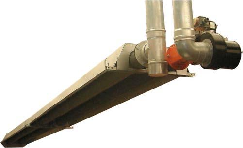
4 3 Scope of Delivery reflector long tube bar reflector short burner unit turnaround box turbulator suspension bracket tube flange packing Fig 1: Radiant tube infraschwank D / calorschwank D 20U Scope of Delivery The radiant tube infraschwank D / calorschwank D consists of: Burner-unit with gas-burner, pre-mixing chamber, ignition and control unit, firing device, gas combination valve (single-, two-stage or modulating), air differential pressure switch, electrical plug connection and fan Radiant tubes with turnaround box, flange packing Corrosion resistant reflector with end cap and brackets for hanging (calorschwank D: isolated reflectors) Accessories Control box with on/off switch and indicator lamp Temperature regulating device Gas cock (gas connection) Gas hose connection Gas filter Supply air- / exhaust flue-system Brackets for wall mounting of angled position (15-30 ) for infraschwank D / calorschwank D Flue gas adapter Ball protection grids (for sport halls) Reflector elongations Set for angled mounting Water protection cover (stainless steel) 4
 7. Test nipple connection pressure 8. Test nipple nozzle pressure 9. Adjustment screw nozzle pressure 10. Adjustment screw start step valve 11.")
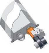
5 Structure of the burner unit Fig. 2: Burner unit 1. Controller 2. Air differential pressure switch 3. Fan air restrictor plate 4. Fan 5. Air baffle plate (only 15 / 20 / 30 / 40U) 6. Gas combination valve (single-, two-stage or modulating) 7. Test nipple connection pressure 8. Test nipple nozzle pressure 9. Adjustment screw nozzle pressure 10. Adjustment screw start step valve 11. Inspection glass 12. Burner cup 13. Burner nozzle 14. Ignition and ionisation electrode 15. Ignition cable 16. Ionisation cable pin power supply socket 18. Locking screw 19. Venturi 20. Burner baffle (only 15 / 20 / 30 / 40U) 21. Gasket 5


6 4 Planning Room temperature control Radiant tube heating-systems must be equipped with a temperature control. Section heating is allowed without temperature control. Position of suspension Suspension height Radiant tubes must be positioned so that no one in the radiation area is exposed to an extreme high heat level. This is ensured when the minimum suspension heights shown in the following table are adhered to: Do not place articles on or against this appliance. Do not use or store flammable materials near this appliance. Do not spray aerosols in the vicinity of this appliance while it is in operation. Nominal thermal load in MJ/h (type) Tab 1: Key: Type Minimum suspension heights A = Minimum height when hanging horizontally B = Minimum height when hanging angled a [cm] Suspension height in m (max. radiation 200 W/m 2 ) A = horizontal B = angled (30 ) 60 (15U) 3.5m 3.1m 75.9 (20U) 4.0m 3.6m (30U) 4.8m 4.3m (40U) 5.5m 4.9m b [cm] c [cm] d [cm] infra calor infra calor 15 U U U U Tab 2: Safe distances Key: a = Minimum radial safety distance (inside radiation area) b = Minimum upper safety distance when hanging horizontally c = Minimum upper safety distance when hanging angled d = Minimum lateral distance to supply pipes outside radiation area Fig 3: Suspension heights and distances for horizontal application Distances to flammable materials in the radiant area Radiant tubes must be positioned so that the surface temperature of components with flammable materials, flammable equipment, stored flammable materials not exceed 65 C above ambient. Fig 4: Suspension heights and distances for angled application Direction of radiation Radiant tubes infraschwank D / calorschwank D can be positioned horizontal or at an angle (max. 30 from vertical). For this purpose suspension steel chains and cables are installed at the suspension brackets. 6
7 Positioning The radiant tube can be mounted with chains (links min. 4 mm) adjustable steel cable (Schwank accessories) If you chose chains please use bolts with lock nuts for fixing the chain to the suspension bracket. The radiant tube has to be fixed by vertical chains etc. to the roof or to supporting devices. wrong Chains and steel cables have to be fixed in vertical direction or slightly diagonally outwards above the fixing points of the suspension brackets to the roof or to supporting devices. Fixing of the suspension cables or chains diagonally inwards to the centre of the heater is not permitted (see Fig 5). Please note that the radiant tube being in operation expands several centimetres because of thermal expansion. Avoid therefore inflexible suspension. Do not use fixing elements like open hooks etc. Hang the heater in balance. We recommend the use of turnbuckles or adjustable steel cable grips for ease of adjustment and balance. Fixing points for chains or steel cables on the heater are shown in Fig. 8 and 9 on pages 12 and 13. Attention! If you do not align the burner unit correctly the device can be damaged. x Correct = vertical or slightly diagonally outwards Fig 6: Slope of radiant tube heater wrong correct SCHWANK GmbH will not accept liability for damages caused by incorrect mounting of the burner unit. Correct mounting is the responsibility of the installer. 15/20/30U: x=15mm 40U: x=20mm x Wrong = diagonally inwards Fig 5: Chains and steel cable mounting 7
8 Air supply / Exhaust Requirements The calculation of air supply / exhaust requirements of a building heated by radiant tube heaters is subject of Australia Standard AS Please follow local bylaws as well. Please see the max. lengths of combustion air supplyand exhaust flue pipe on page 9 (Tab 3, point 3). Place of Installation The room to be heated must have an air volume of minimum 10 m³ for each kw of the nominal thermal load of the installed heater. Air supply (combustion air from inside the room, types A3 and B23) Heating installations with combustion air from inside the room are only allowed in rooms without string air pollution. Otherwise use system with combustion air from outside (type C). In halls and buildings with a normal air change by means of joints and gaps it is not necessary to install additional equipment to ensure combustion air supply. Air supply / exhaust systems For the radiant tube infraschwank D / calor SchwankD the following air supply / exhaust systems are possible: 1. Indirect flue into the room (Type A3 without exhaust system, combustion air from inside the room) 2. Flued with individual exhaust system, combustion air from inside the room (Type B23) 3. Flued with individual exhaust system, combustion air from outside the room (Type C) 4. Flued with flue collecting system and central flue fan combustion air either from inside or from outside (according to EN 777, Type D) 1. Indirect flue into the room (Type A3 without exhaust system combustion air from inside the room) The exhaust air of the tube heater has to be conducted from the inside of the room to the outside. Conduction of the exhaust air may be carried out with one of the following 3 methods: a) Thermal ventilation: Combustion air and exhaust air are to be conducted through fixed outlets positioned on the roof or on the walls of the building. b) Mechanical ventilation: Combustion air and exhaust air are to be conducted through one or more fans positioned on the roof or on the walls of the building. c) Natural ventilation: Combustion air and exhaust air are to be conducted through outlets as a result of differences in pressure and in temperature between the internal and external side of a building. For exact dimensioning and positioning of supply air and exhaust air outlet of the building according AS 5601 or please contact Schwank GmbH 8
9 2. Exhaust flue with individual exhaust system - combustion air from inside the room (Type B23) Only use this system in rooms with no air pollution and without relevant pressure differences to outside. Otherwise use type C. 3. Exhaust flue with individual exhaust system - combustion air from outside the room (Type C) Combustion air and exhaust air are to be conducted by a temperature stable, concentric pipe from a wall or roof entrance. Max. length of the concentric pipe can be 6 m plus two 90 elbows. The concentric pipe ends at a bifurcated pipe. Please ensure that the connection for exhaust air between heater and bifurcated pipe is a flexible pipe. Do not use back-pressure valves or dampers in the exhaust flue. infraschwank D/ calorschwank D, shape U Max. length between heater and roof/wall entrance Tab 3: air / exhaust flue max. number of elbows (90 ) Ø of air/exhaust flue 6 m mm 4. Exhaust flue with flue collecting system and central flue fan (according to EN 777, Type D) The heating installation must not exceed 10 radiant tubes. The exhaust air of each tube is collected via a central collecting tube system by a central flue fan and led to the chimney. Planning, construction and layout of such installations must be carried out by Schwank employees, as well as commissioning. The strict observance of the Schwank layout-drawings and calculation figures are the precondition of the manufacturer s warranty. If the radiant tubes will be installed without their individual flue fans, please note that it could be necessary to install in the collecting tube behind each radiant heater a damper or a pressure-balancing device. This ensures a precise regulation and an even exhaust flue of each radiant tube. See technical instruction infraschwank D / calorschwank D with flue collecting system 9
 is mounted in a position so that the flue gas is diverted from the burner.")
10 Indirect flue into the room with flue gas diverter Installation with indirect flue into the room must be mounted with flue gas diverter to avoid flow back of flue gas in combustion air stream. Note that the flue gas diverter (code no ) is mounted in a position so that the flue gas is diverted from the burner. To prevent CO 2 impingement on wall when configured as an indoor flue less appliance a clearance of 1200mm from the flue outlet is required. flue gas diverter with right mounting position Fig 7: Flue less appliance with flue gas diverter 10
11 5 Legal Requirements We recommend that these installation guidelines should be observed with the relevant Building Standards Regulations of your country. Comply with any local by-laws and the current IEE Wiring Regulations. Notwithstanding their limited scope, the appliance should be installed by a competent person in accordance with the relevant provisions of the Gas Safety (Installation and Use) Regulations. Caution must also be taken of any obligations arising from the Health and Safety of Work Act. Full compliance with all relevant regulations, including amendments in force at the time of installation is a requirement of our warranty. 6 Operating The installation must be carried out by a qualified engineer following the manufacturer s instructions. SCHWANK will not accept liability damages caused by improper assembly and/ or operating of the heater. Proper assembly and operation is the responsibility of the user. Switching on the heater Switch on the heater. The main switch is on the control box. After a pre-purge period of about 25 sec. the ignition starts. Switching off the heater Switch off the heater. If the radiant tube is controlled by a thermostat the heater will be switched on and off automatically. Fault If no flame is reported during the pre-purge period and the safety time (approx. 30 sec.) the heater repeats the ignition process. If there is no flame after the second ignition process the radiant tube switches off automatically and is locked. Investigation and repair must be carried out by authorized personnel. After clearance of the fault the heater can be reset. Lock release (Reset) Interrupt the electric power supply for 3 seconds. Maintenance Maintenance and servicing of the appliance must be carried out by authorised personnel and not less than once a year. Servicing of the heater is essential for continued efficient operation. After any servicing, the heater must be recommissioned as detailed in Chapter


12 7 Technical specification Appliance Automatic heating device, heat transfer by mean of infrared dark radiation. Fuel Types Natural gas Propane Minimum connection pressure in front of valve Type 15-40U Natural Gas 1.13kPa LPG 2.75kPa Attention! Max. connection pressure Natural Gas: 5.0kPa Electrical connection Single phase A.C. 230 V, N, PE - 50Hz (cycles) (approx. 80 VA) Power supply for the heater and fan are connected to the socket of the burner box. To set the burner box free of voltage, it is only necessary to remove the plug of the power supply. The connection cable for the lifting magnet of 2-stage gas combination valve must connect from the connection box (230 V/50 Hz) to the provided luster terminal inside of the burner unit. The connection cable for the lifting magnet of modulating gas combination valve must connect direct from the modulation box to the lifting magnet. The distance between modulation box and burner unit should be < 1,5m. Exhaust gas Flue gas pipe connection Ø 100 Connection at exit of tube infraschwank D / calorschwank D 15U (all dimensions in mm) infraschwank D / calorschwank D 20U (all dimensions in mm) Gas connection 15-30U 40U Detail A / B R=1/2 male R=3/4 male Detail A Cross dimensions at burner unit 15-40U A=80mm Detail B Cross dimensions reflector valid for all types Fig 8: Measurements infraschwank D / calorschwank D 15U and 20U (view from below) 12
 Fig 9: Measurements infraschwank D / calorschwank D 30U and 40U (view from")
13 infraschwank D / calorschwank D 30U (all dimensions in mm) infraschwank D / calorschwank D - shape U infraschwank D / calorschwank D 40U (all dimensions in mm) Fig 9: Measurements infraschwank D / calorschwank D 30U and 40U (view from below) 13
14 Technical data for single and two-stage regulation Gas Natural gas Gas consumption [MJ/h] 1) single state infraschwank D / calorschwank D 15U 20U 30U 40U Gas consumption [MJ/h] 2-stage/modulating max./min. Propane Gas consumption [MJ/h] 2) 2-stage/modulating max./min , Gas consumption [MJ/h] 2-stage/modulating max./min Weight infra / calor [kg] 54 / / / / 171 of air/exhaust flue [mm] Electrical consumption [W] Electrical protection Ø IP 20 Gas connection (male) R½ R 3 / 4 Electrical supply Ignition / Control 230 V/ 50 Hz ~ Spark ignition and ionisation control by automatic controller system CE-Identification AGA Certification no. CE BO ) H i,b = 37.8 MJ/m 3 / 2) H i,b = 95.8 MJ/m 3 Tab 4: Technical data infraschwank D / calorschwank D Gas infraschwank D / calorschwank D 15U 20U 30U 40U Natural gas Burner nozzle [mm] ) Fan air restrictor plate D 15 D 20 D 30 D 40 Air baffle plate D 15 D 20 D 30 + spin D 40 U Burner baffle plate Ø 50 Ø 50 Ø 65 / Nozzle pressure [kpa] 1-stage stage 0.87 / / / / 0.6 Start step pressure [kpa] Start step adjustment [ ] MIN MIN MIN MIN Propane Burner nozzle [mm] ) Fan air restrictor plate D 15 D 20 D 30 D 40 Air baffle plate D 15 D 20 D 30 + spin D 40 U Burner baffle plate Ø 50 Ø 50 Ø 65 Ø 65 Nozzle pressure [kpa] 1-stage stage 2.4 / / / / 1.4 Start step pressure [kpa] Start step adjustment [ ] MAX MAX MAX MAX 1) H i,b = 37.8 MJ/ m 3 / 2) H i,b = 95.8 MJ/m 3 *) IA= inlet angle plate Tab 5: Function parts burner unit infraschwank D / calorschwank D
15 8 Operating description Start-up If heat demand exists, the fan will start up automatically. A differential pressure arises in the burner box, which is reported to the ignition unit via the differential pressure switch. After a pre-purge period of about 25 seconds the automatic ignition starts (max. ignition time 5 sec.). The twin solenoid valve with pressure regulator opens the gas supply to the burner in 2 steps. The burner flame is controlled by an ionisation electrode. The ignition is switched off, if the ionisation electrode reports a flame to the ignition and control unit within the safety time. If the ignition process fails, the ignition unit repeats the start-up for one more time. Fault If no flame is reported during the pre-purge period (including 1 repetition of ignition process), the ignition unit will switch off the radiant tube and will lock it. Investigation and repair must be carried out by authorized personnel only. After clearance of the fault, the interlock can be reset. The lock release can carried out by an interruption of the electric power supply for 3 sec. A new start-up begins. If no flame signal is reported to the ignition and control unit during operation, the solenoid valve shuts and stops the gas supply immediately. A new start-up process is repeated. Operation A very long laminar flame is created in the first tube by the special burner construction. The hot flue heats the tube surface while being fed through the tubes by the fan. The hot tubes emit long-waved infrared radiation which is directed to the room by the reflector construction. The radiant tube infraschwank D / calorschwank D work with a closed combustion system. The combustion air is taken from the room or from the outside. The flue is evacuated indirectly into the room or directly by the exhaust pipe or by a special air/exhaust pipe system. For optimal adaption of heaters performance to the heat demand of the building heaters are offered in 2-stage or modulating operation. Start and ignition of the heater has always to be in full load. After a time of minimal 1 minute the heater can be switched to small step.. Troubleshooting: page 28 Monitoring of the combustion air supply The combustion air supply is permanently controlled by the differential pressure switch during the operation. If the differential pressure switch is not in rest position during the start-up the operation will not start. If the operating contact is not closed during the pre-purge the system will set in interference release. If combustion air supply fails during operation (lack of air), the differential pressure switch will close the gas combination valve and stop the gas supply. A new startup process is to be repeated. 15
. Start mounting the heater at the turnaround box connection.")
16 9 Assembly instructions infraschwank D / calorschwank D 15U Tools you need hexagonal wrench or ratchet (width: 10, 13) socket wrench (width: 7 and 8) Note before mounting Note the distance measure of suspension brackets. Flanges are mounted with flange packing (each 4 screws/washers/lock washers/nuts M8). Start mounting the heater at the turnaround box connection. Turn welding line of the tubes to the side. Tube with turbulator (with paint mark) has to be mounted behind the turnaround box (flow direction). The paint mark showing to the turnaround box! Tube bars have to be fixed by nuts/lock washers/3dwashers M8 on the suspension bracket. First the reflector will be fixed on the U-bend connection by self-tapping screws. For insulated reflectors (calorschwank D) the reflector end with notch on sides shows to the turnaround box. The other reflector ending will be shoved under the clip of the suspension brackets. Reflector and front plate have to be fixed by self-tapping screws. Mounting of burner unit with valve on the top. Indirect flue into the room (Type A3): Flue gas diverter code no Note that the flue gas diverter is mounted in a position so that the flue gas is diverted from the burner. Accessory: Flue gas adapter code no Adapter is mounted at the end of the tube with gasket. Flue gas connection (Type B23, C): version stainless steel: Note that the flue gas flexible pipe is mounted at the end of the tube with gasket. Fig. 10: Mounting of infraschwank D / calorschwank D 15U (all dimensions in mm) Flue gas diverter 16
.")
17 Assembly infraschwank D / calorschwank D 20U Tools you need hexagonal wrench or ratchet (width: 10, 13) socket wrench (width: 7 and 8) Version 004 infra_calor D D shape U U Australia 43/13 Technical specification subject to to change Note before mounting Note the distance measures of suspension brackets. Flanges are mounted with flange packing (each 4 screws/washers/lock washers/nuts M8). Start mounting the heater at the turnaround box connection. Turn welding line of the tubes to the side. Tube with turbulator (with paint mark) has to be mounted behind the turnaround box (flow direction). The paint mark showing to the turnaround box! Tube bars have to be fixed by nuts/3d-washers/lock washers M8 on the suspension brackets. Start the reflector mounting at the turnaround box connection with the longest reflector L=3000mm. Reflector will be fixed on the turnaround box connection by self-tapping screws. For insulated reflectors (calorschwank D) the reflector end with notch on sides shows to the turnaround box. The other reflector endings will be shoved under the clips of the suspension brackets. The short reflector L=1500mm is mounted at the front of the heater. Reflectors will be jointly fixed by 3x M 5 screws and self-locking nuts. Reflector and front plate have to be fixed by selftapping screws. Mounting of burner unit with valve on the top. Indirect flue into the room (Type A3): Flue gas diverter code no Note that the flue gas diverter is mounted in a position so that the flue gas is diverted from the burner. Accessory: Flue gas adapter code no Adapter is mounted at the end of the tube with gasket. Flue gas connection (Type B23, C): version stainless steel: Note that the flue gas flexible pipe is mounted at the end of the tube with gasket. Fig. 11: Mounting of infraschwank D / calorschwank D 20U (all dimensions in mm) Flue gas diverter 17
.")
18 Assembly infraschwank D / calorschwank D 30U Tools you need hexagonal wrench or ratchet (width: 10, 13) socket wrench (width: 7 and 8) hand rivet tool, drill machine, drill 4.9mm Note before mounting Note the distance measures of suspension brackets. Flanges are mounted with flange packing (each 4 screws/washers/lock washers/nuts M8). Start mounting the heater at the turnaround box connection. Turn welding line of the tubes to the side. Tube with turbulator (with paint mark) has to be mounted behind the turnaround box (flow direction). The paint mark showing to the turnaround box! Supporting sleeve for first flange connection: Insert half of the supporting sleeve into first heater tube (slot on top). Drill Ø 4.9mm hole through the tube and sleeve and fix it by rivet. Mount the second tube and fix the sleeve by the rivet as well. Fix the rivets always in the opposite position lateral to the tube. Use only stainless rivets. Tube bars have to be fixed by nuts / 3D washers / lock washers M8 on the suspension brackets. Start the reflector mounting at the turnaround box connection. Reflector will be fixed on the turnaround box connection by self-tapping screws. For insulated reflectors (calorschwank D) the reflector end with notch on sides shows to the turnaround box. The other reflector endings will be shoved under the clips of the suspension brackets. Reflectors will be jointly fixed by 3x M 5 screws and self-locking nuts. Reflector and front plate have to be fixed by selftapping screws. Mounting of burner unit with valve on the top. Indirect flue into the room (Type A3): Flue gas diverter code no Note that the flue gas diverter is mounted in a position so that the flue gas is diverted from the burner. Accessory: Flue gas adapter code no Adapter is mounted at the end of the tube with gasket. Flue gas connection (Type B23, C): version stainless steel: Note that the flue gas flexible pipe is mounted at the end of the tube with gasket. Supporting sleeve 4 rivets (stainless steel) 4,8mm hole to drill 4,9mm Fig. 12: Mounting of infraschwank D / calorschwank D 30U (all dimensions in mm) 18 Flue gas diverter

19 Assembly infraschwank D / calorschwank D 40U Tools you need hexagonal wrench or ratchet (width: 10, 13) socket wrench (width: 7 and 8) infraschwank D / calorschwank D - shape U Version 004 infra_calor D D shape U U Australia 43/13 Technical specification subject to to change Note before mounting Note the distance measures of suspension brackets. Flanges are mounted with flange packing (each 4 screws/washers/lock washers/nuts M8). Start mounting the heater at the turnaround box connection. Turn welding line of the tubes to the side. Tube with turbulator (with paint mark) has to be mounted behind the turnaround box (flow direction). The paint mark showing to the turnaround box! Tube bars have to be fixed by nuts/3d-washers/lock washers M8 on the suspension brackets. Start the reflector mounting at the turnaround box connection. Reflector will be fixed on the turnaround box connection by self-tapping screws. For insulated reflectors (calorschwank D) the reflector end with notch on sides shows to the turnaround box. The other reflector endings will be shoved under the clips of the suspension brackets. Reflectors will be jointly fixed by 3x M 5 screws and self-locking nuts. Reflector and front plate have to be fixed by self-tapping screws. Mounting of burner unit with valve on the top. Indirect flue into the room (Type A3): Flue gas diverter code no Note that the flue gas diverter is mounted in a position so that the flue gas is diverted from the burner. Accessory: Flue gas adapter code no Adapter is mounted at the end of the tube with gasket. Flue gas connection (Type B23, C): version stainless steel: Note that the flue gas flexible pipe is mounted at the end of the tube with gasket. Fig. 13: Mounting of infraschwank D / calorschwank D 40U (all dimensions in mm) Flue gas diverter 19
20 10 Installation instructions a Danger of fire and explosion! Unprofessional handling of gas pipes, gas connections and the appliance can produce gas leaks. It is highly dangerous if gas is ignited! Working on gas pipes and the appliances is only allowed by approved installers. Mount the flexible connection, so that it can compensate the longitudinal expansion of the tube. Only use flexible connections for the radiant tube regarding: gas electricity and air (if necessary) b Fig 14: Longitudinal expansion Gas-pipe-system and mounting of heaters pressure drop value of the Schwank gas-pipe-systems see table 7. Minimum connection pressures in front of valve Natural gas* infraschwank D / calorschwank D shape U type min. connection pressure [kpa] nozzle pressure single stage [kpa] two stage max. - min. [kpa] start step pressure [kpa] 15-40U Propane* 15-40U * Natural gas: H S, B : 37,8 MJ/m 3 Propane: H S,B 95.8 MJ/m 3 Tab 6: min. connection pressures with single and two stage regulation in front of gas combination valve Pressure drop Schwank gas-pipe-systems infraschwank D / calorschwank D shape U Natural gas Propane type gas pipe system pressure drop [kpa] 15-30U 1/2" / L=800mm U 3/4" / L=800mm U 1/2" / L=800mm U 3/4" / L=800mm 0.1 Tab 7: Pressure drop Schwank gas-pipe-systems The max. connection pressure for natural gas is 5.0kPa! In case of contaminated gas pipes and generally at gas pipes of welded black steel have to be mounted gas filter - groups directly in front of the heater (see page 35). All gas installation work must be carried out only by an authorised person in accordance with standard AS Additional installation notices of national or local institutions must be observed. The pipe must be dimensioned in a way that the minimum connection pressure in front of the gas combination valve of the individual devices is available at the nominal thermal load of the entire system, according to table 6. Please consider the pressure drop of the upstream mounted gas connection and gas filter. For the detailed Flexible final connections to the heater must either a) hose assembly to AS/NZS 1869 of a suitable size, temperature and pressure rating or b) a limited flexibility connector to AS 4631 of a suitable size. 20
21 Note the following points while installing the gas-pipe-system: Use only gas lines as per national standards. Never hang heaters on the gas pipes. Mount a manual gas cock upstream of every radiant tube. Close all gas cocks before carrying out the leak test and disconnect the connection between the gas cock and the burner to avoid damages to the gas regulator and gas combination valve. Clean gas pipes before the installation of the heater. Reconnection after pressure control and expansion. Please observe the national standards. 430 mm (+/- 10%) Fig 16: lateral connection 90 bend 430 mm (+/- 10%) Fig. 16: lateral connection 90 bend Connect the heater with an approved flexible hose. Use the following hose length: 15-30U R ½ length 800mm 40U R ¾ length 800mm Mount only a flexible hose with 90 bend or with 2 x 90 elbow with 180 bend according to fig. 15, 16 and 17. Keep the specified installation dimensions. Wrong mounting of flexible hoses shown in Fig. 18 (sketches to) Fig. 17: Alternative flexible hose 180 -bend with 2 x 90 elbow a = 320 mm +/- 10% h = 150 mm h: allowable height displacement for mounting 430 mm (+/- 10%) 430 mm (+/- 10%) Fig 15: Stand connection 90 bend Fig 18: Wrong mounting of flexible hoses 21
22 Gas connection has to be positioned in the axle of the heater. Otherwise torsional forces will operate on the hose! Avoid twisting of the flexible hose! (When tightening the union, counter hold the nipple on the hose.) Pay attention that the flexible hose will not be mechanically damaged by tools etc. Do not buckle the hose. Do not mount damaged flexible hoses! Damaged hoses can break due to the movement of the heater. Electrical installation (wiring diagram) Danger of electric shock! Electric shocks are highly dangerous! Working at the electrical equipment of the appliance is only allowed by professional personnel observing the current IEE regulations. Isolate the electrical supply while working at the electrical equipment of the appliance and safeguard the appliance against unintentional connection to the circuit. The gas supply and electrical cable must be situated on the outside of the radiation and combustion heat. Only use heat-resistant cables near the tubes. Electrical connection Single stage operation Route the connection cable (power supply) to the three-pin plug and connect the cables (see Fig. 19, page 23). Plug in the three-pin plug into the socket of the burner box. Connect the plug of the fan into the corresponding socket at the burner box. Electrical connection two stage operation Route the connection cable (power supply burner unit) to the three-pin plug and connect the cables (see Fig. 20, page 23). The connection cable of the modulation spool connects by a branch box (see Fig.20, page 23). Plug in the three-pin plug into the socket of the burner box. Connect the plug of the fan into the corresponding socket at the burner box. Start and ignition of the heater has always to be in full load. After a time of minimal 1 minute the heater can be switched to small step. You find the three-pin socket for the electrical supply on the burner box. The connection cable of the modulation spool is screw on the gas combination valve. 22 Pay attention of the correct polarity! If the polarity is incorrect, the firing device will not note any ionisation signal! You find the three-pin socket for the electrical supply on the burner box.
23 Gas valve VK 4105C Burner unit 1 2 PE L N PE Control box Thermocontrol Plus M / unoschwank single-stage operation L N PE Electrical supply 1~230Volt, 50Hz, N, PE Fig. 19: Connecting diagram single-stage regulation infraschwank D / calorschwank D Version 004 infra_calor D D shape U U Australia 43/13 Technical specification subject to to change Gas valve VK4115Q / VK 4105Q with lifting magnet 2-stage Time delay 1minute ignition for max. load (integrated in control box duoschwank and Thermocontrol Plus M) two-stage operation Burner unit Control box Thermocontrol Plus M / duoschwank L1 N PE Electrical supply 1~230Volt, 50Hz, N, PE Fig. 20: Connecting diagram two-stage regulation infraschwank D / calorschwank D 1 2 PE Connection box L1 L2 N PE 23
 modulating operation L1 L2 N PE Control box Thermocontrol Plus M / moduschwank L1 N P Electrical supply 1~230Volt, 50Hz, N, PE Fig.")
24 GVK VK 4105N with modulating lifting magnet Burner unit 1 2 PE o Modulation Box (distance to burner unit < 1,5m) Time delay 1minute ignition for max. load (integrated in moduschwank and Thermocontrol Plus M) modulating operation L1 L2 N PE Control box Thermocontrol Plus M / moduschwank L1 N P Electrical supply 1~230Volt, 50Hz, N, PE Fig. 21: Connecting diagram modulating operation infraschwank D / calorschwank D Fig 22: Wiring diagram burner unit infraschwank D / calorschwank D 24
25 Version 004 infra_calor D D shape U U Australia 43/13 Technical specification subject to to change 11 Commissioning instructions Before commissioning Only authorised personnel can curry out this operation. The correct operation and fixing of the heater is prerequisite for the warranty. Checking gas lines and flue system is not included in this service. Check the function of the following equipment: Exhaust flue Combustion air supply Control unit Safety equipment Safety of electrical circuit Pay attention when commissioning! Vaporization of remaining grease of metal units may cause greasy mist. This kind of mist disperses after approx. 30 minutes. During this time the room has to be ventilated. Adjusting nominal thermal load at single-stage operation Attention! The pressure control unit is preadjusted on natural gas / propane. Do not put the appliance into operation uncontrolled. Adjusting the nozzle pressure 1. Open first the gas cock which is at the end of the flexible gas hose (Fig.23, page 26). 2. Open the test nipple connection pressure. Connect the pressure measuring instrument to the test nipple and determine the connection pressure. Close the test nipple after the measurement! 3. Open the test nipple nozzle pressure. Connect the pressure measuring instrument to the test nipple and determine the nozzle pressure. 4. Turn the adjusting screw on the pressure regulator slowly in the + or - -direction while continuously watching the pressure measuring instrument. Stop turning as soon as the required nozzle pressure is reached. The required nozzle pressure for natural gas H (W o,b =50.0 MJ/m 3 ) is shown in table 5 page Remove the protection cap A (see Fig. 24, page 26). 6. Put the radiant tube into operation 7. Turn the adjusting screw B (see Fig. 25, page 26) on the pressure regulator slowly in the + or - - direction while continuously watching the pressure measuring instrument. Stop turning as soon as the required nozzle pressure is reached. 8. Put the protection cap A on the valve after the adjusting. 9. Close the test nipple after the measurement and check if the test nipple is gas-tight. Checking adjustment 1. Turn the adjustment screw slightly to - -direction. Nozzle pressure must drop immediately. If this does not happen, you must readjust the jet pressure until the point is reached at which a decrease or increase in the nozzle pressure is noticeable on the measuring instrument. 2. Close test nipple after the measurement! 3. Remove the measuring instrument and check if the test nipple is gas-tight. 25


 from the lifting magnet (lift the cap with a small screw-driver) 6. Put the radiant tube into operation. 7.")
26 Adjusting thermal load at two-stage operation Adjusting the nozzle pressure 1. Open first the gas cock at the end of the flexible gas hose (Fig.23, page 26). 2. Open the test nipple connection pressure. Connect the pressure measuring instrument to the test nipple and determine the connection pressure. Close the test nipple after the measurement! 3. Open the test nipple nozzle pressure. Connect the pressure measuring instrument to the test nipple and determine the nozzle pressure. 4. Turn the adjusting screw on the pressure regulator slowly in the + or - -direction while continuously watching the pressure measuring instrument. Stop turning as soon as the required nozzle pressure is reached. The required nozzle pressure for natural gas H (W o,b =50.0 MJ/m 3 ) is shown in table 5 page Take off the plastic cap E (see Fig. 25, page 26) from the lifting magnet (lift the cap with a small screw-driver) 6. Put the radiant tube into operation. 7. The electrical supply must activate for burner unit and lifting magnet to adjust the nozzle pressure of max. load. Turn the outer adjusting screw C (width 8) until the required nozzle pressure is reached. 8. The electrical supply must activate only for the burner unit to adjust the nozzle pressure of min. load. Turn the inner adjusting screw D (screwdriver 6x1) until the required nozzle pressure is reached. 9. Checking adjustment nozzle pressure as described by the single stage performance. 10. Close test nipple after the measurement and and check if the test nipple is gas-tight. 11. Put the plastic cap E on the lifting magnet. Fig 23: Fig 24: C Gas cock with integrated TSD Adjusting screw nozzle pressure single stage gas combination valve D A B E Fig 25: Adjusting screw nozzle pressure with lifting magnet two stage gas combination valve 26
27 Version 004 infra_calor D D shape U U Australia 43/13 Technical specification subject to to change Adjusting thermal load for modulating operation Adjusting the nozzle pressure 1. Open first the gas cock which is at the end of the flexible gas hose (Fig.23, page 26). 2. Open the test nipple connection pressure. Connect the pressure measuring instrument to the test nipple and determine the connection pressure. Close the test nipple after the measurement! 3. Open the test nipple nozzle pressure. Connect the pressure measuring instrument to the test nipple and determine the nozzle pressure. 4. Turn the adjusting screw on the pressure regulator slowly in the + or - -direction while continuously watching the pressure measuring instrument. Stop turning as soon as the required nozzle pressure is reached. The required nozzle pressure for natural gas H (W o,b =50.0 MJ/m 3 ) is shown in table 5 page Take off the plastic cap A (see Fig. 26, page 27) from the lifting magnet. 6. Put the radiant tube into operation. In case a different value has to be set the output current value in the Modulation Box has to be changed. Please follow below mentioned procedure [e.g. 12 / 8.5 mbar]: 7. Switch the jumper at the ThermoControl Plus M to Modulation 8. Switch on the Chimney sweeper mode at the ThermoControl Plus M 9. Ensure that the input pressure at the gas pressure regulator is sufficient enough [e.g. 15 mbar] 10. Push the +/- button (button block B ) so that the measured nozzle pressure will be 1 mbar below the required minimum value (e.g. 7.5 mbar). If the value cannot be adjusted, the mechanical limitation at the lifting magnet (large adjusting screw B, Fig. 26) needs to be amended. Afterwards continue with adjusting to the required minimum value 11. To adjust the maximum pressure, the jumper has to be switched to Max. With the +/- buttons adjust the value to 1 mbar above the required maximum pressure (e.g. 13 mbar). In case the value cannot be adjusted the mechanical limitation of the lifting magnet (small adjusting screw C, Fig. 26) needs to be amended. Afterwards continue with adjusting to the required minimum value. 12. Check the minimum value and re-switch the jumper to min position and adjust the value if necessary (e.g. 7.5 mbar). 13. Adjustment of the mechanical pressure range of the lifting magnet: Place the jumper of the Modulation Box to the N position. Chimney sweeper mode needs to be still switched on. Disconnect the power supply (clamp 7 / 8, Fig. 27) of the Modulation Box or the connector of the lifting magnet. Adjust the minimum value to the required nozzle pressure (e.g. 8.5 mbar) at the lifting magnet. Re-connect the electrical connection at the Modulation Box (clamp 7 / 8) or the connector of the lifting magnet and adjust the required maximum value (e.g. 12mbar) at the lifting magnet. 14. Switch off the chimney sweeper mode. 15. Close test nipple after the measurement and and check if the test nipple is gas-tight. 16. Put the plastic cap A on the lifting magnet Fig. 26: Section of modulating lifting magnet Fig. 27: Modulation Box 27
28 12 Service guide / Trouble shooting Maintenance and annual check A regular maintenance is the requirement for a faultless operation of the appliance. According to the National Standard Regulations, heating-systems with radiant tubes must be checked at least once a year. Maintenance and trouble shooting is only allowed by professional personnel that is competent and instructed in radiant tubes. Maintenance must include the following checks: Check the surface of radiant tubes Check the pollution and sooting of tubes clean (if necessary) Check tightness of the tube system including connection to the burner unit Check the air/flue-system clean (if necessary) Check the gas connection Leakage-test Check the connection pressure, nozzle pressure and start step Check gas filter in case of reduced line pressure, in case of pollution change filter set Check the safety functions of the ignition- and ionisation-controls Check the valve functions Check the function of the pressure switch Check the electrical connections Check the slope of the tubes (3 mm/m in direction of the turn around box connection) Check the flexible gas hose and electrical connection to the burner unit Check the room temperature control Check the distances to any flammable materials Check the air/flue ventilation of the room Remove condensation water in the tube Check correct connection of the reflectors Check if the fan impeller runs correctly and is free of any damages Check the tight fit of the fan venturi Check connection and tightness of the fan to the burner unit Any deviations must be fixed immediately. Defect parts must be changed directly. Pressure switches, pressure regulators, valves and safety- and ignition devices can only be maintained by the manufacturer or authorized personnel. Trouble Shooting fault reason No gas (check pre- and nozzle Burner does not start pressure) Fault in electrical supply Thermostat "OFF" Connection of ignition- and ionisation electrode is wrong Differential pressure switch is defect or out of order (contact must be open) Control goes in fault position during prepurge period Control goes in fault position during the safety time In case of doubt, please contact: Mr. John Balass Devex Systems Pty Limited 5/83 Bassett St Mona Vale NSW 2103 Tel: Fax: Flame signal wrongfully caused by electrical defect of control Pressure differential is not sufficient No flame (no ignition, valve doesn't open, no gas) No or poor flame signal (flame does not stick, bad insulation of the flame detector, no contact between burner and earth connection) Wrong polarity Control goes into Flame is off fault position during operation Contact of differential pressure switch opens Flame signal is poor 28
29 13 Change of gas family infraschwank D / calorschwank D - shape U Fig 28: Change of gas family Burner baffle (only 15 / 20 / 30 / 40U) Burner cup Burner nozzle Regulation screw start step Air baffle plate (only 15 / 20 / 30 / 40U) Fan air restrictor Instruction to change the gas family 1. Change the burner nozzle 2. Adjust the new nozzle pressure (see tab. 5, page 14) Instruction to adjust start step pressure 1. Adjust the start step pressure with the regulation screw, the pressure rise and the opening time can be changed between set limits. 2. The start step pressure must be set as the specified values in tab 8. Turn it clockwise with a screwdriver to increase the start step. infraschwank D / calorschwank D shape U gas type adjustment start step pressure regulation screw [kpa] Natural 15-30U MIN 0.4 gas 40 U MIN Adjust the new start step pressure (see tab 8, page 29 ) 4. Stick on the new rating label Propane 15-40U MAX 1.2 Tab 8: Setting regulation screw start step 29
30 14 Accessories Ball guards Ball protection grids acc for using heaters in sport halls (grid 40x40mm). Delivery scope Mounting set complete for each type of heater existing of: infra/calorschwank D shape U 15U 20U 30U 40U Ball protection grid L=1443mm Ball protection grid L=1843mm 2x 2x 2x Ball protection grid L=2203mm 1x Ball protection grid L=2963mm 1x 1x 2x Protection grid burner top 1x 1x 1x 1x Front protection cover burner 1x 1x 1x 1x Protection grid burner end side 1x 1x 1x 1x End bracket with stud bolts M8 1x 1x 1x 1x Holding bracket (1x infra D +1x calor D) 1x 1x 1x Angled bracket with stud bolt M8 4x 4x 6x 8x Clamp 6x 6x 8x 10x Set fixing material 1x 1x 1x 1x Assembling (Description for heater infra/calorschwank D 30 U, other types similar) 1. Mounting heater as usually acc. manual (see chapter 9, page 16-19). 2. Fix end bracket at inner side of turnaround box, open and close again 4 nuts M8 (Fig. 30, page 32) 3. Fix two angled brackets at each tube hanger (screws M8 x 60, nuts) (Fig. 31, page 32) Screw on angled brackets at the inner holes of suspension bracket. 4. Holding bracket put loose on the first reflector (view from burner unit) and screw together with two angled brackets (screws M8 x 60, nuts), holding bracket remain axially movable NOTE: Use the right holding bracket difference infraschwank D or calorschwank D both in the delivery scope (Fig. 32, page 32)! 5. Assembling segments ball protection grids starts on the turnaround box (last suspension bracket for shape L). Put first segment ball protection grid L=2963 mm from below on end bracket and angled brackets of the next suspension bracket Put clamps on stud bolts M8 and mount with self-locking nuts Mount clamp loose on one stud bolt of angled bracket for further assembling next protection grid (Fig. 33, page 32). 6. Put next segment ball protection grid L= 1843mm from below on angled brackets and mount clamp with self-locking nuts M8, clamp and angled bracket connect two segments ball protection grid to each other. Mount clamp loose on one stud bolt of angled bracket for further assembling next protection grid. 7. Put next segment ball protection grid L= 1843mm from below on angled brackets and mount clamps with self-locking nuts M8 Last segment ball protection grid L= 1843mm protects the burner unit at the bottom. 30

31 Version 004 infra_calor D D shape U U Australia 43/13 Technical specification subject to to change 8. version stainlessafter finish assembling of all ball protection grids fix holding bracket with 3x self-tapping screws on the reflector. 9. Push on protection grid burner top from behind over ball protection grid and burner up to the suspension bracket. Note that the lower short bending is on the left side in view from behind. Fix burner protection grid burner top with supplied cable straps or similar at bottom protection grid. 10. Protection grid burner top has to be cut holes depends on installation on-site for flue system and may be gas line. Connect flue system pipes and gas line. NOTE: Select the cutouts large enough to compensate the thermal length expansion of the heater! 11. Insert front protection cover burner between front cover plate reflector and burner unit and fix it with supplied cable straps or similar on protection grid burner top (Fig. 34, page 32). 12. Protection grid burner end side has to be cut hole depends on installation on-site for gas line. Fix with supplied cable straps or similar on protection grid burner top. Please note the required number and length of segments ball protection grids for each type of heater. Compare this to the tabular and graphical overview. Fig. 29: Overview of ball guards 31


32 Fig. 30: Fixed end bracket on turnaround box Fig. 33: Loose mounted clamp Fig. 31: Fixed angled bracket on suspension bracket Holding bracket calor D shape U Holding bracket infra D shape U Fig. 34: Fixing front protection cover burner on protection grid burner top Fig. 32: Holding bracket infra D and calor D 32
 is depend on required protection (one side both side, protection length) and the power of the radiant heater.")
. 2. Fix screws with distance sleeve and mounting angles A at hangers as required. 3. Mount end bracket B at turn around box. 4.")

.")
33 Version 004 infra_calor D D shape U U Australia 43/13 Technical specification subject to to change Reflector elongation Vertical elongation of reflectors b=415mm for thermal protection. The numbers reflector elongation (single sheets) is depend on required protection (one side both side, protection length) and the power of the radiant heater. Delivery scope Reflector elongation consist of numbers of sheet reflector elongation mounting material Assembling 1. Assembling and mounting tubes with reflectors complete acc. manual (see chapter 9, page 16-19). 2. Fix screws with distance sleeve and mounting angles A at hangers as required. 3. Mount end bracket B at turn around box. 4. Put reflector elongation sheet B on mounting angle A. Screw both parts together with the added clip C and screw/nut M8 and lock a nut to ensure the reflector elongation sheets. 5. Fix reflector elongation sheets to another with screw/nut M8. At heaters with axial reflector elongation the last suspension bracket on the burner side must be mounted at the junction point reflector/reflector end plate. A D C Set angled mounting tubes Bracket to ensure form and position of reflectors when the heater is mounted angled (>15 ). Bracket to mount at each junction point reflector/reflector, not at reflector end caps. Delivery scope Mounting set consist of numbers of brackets mounting material Assembling 1. Assembling and mounting of tubes complete (without reflectors) acc. manual (see chapter 9, page 16-19). 2. Lay first reflector on turn around box and first hanger, fix it at turn around box with two screws. 3. Fix angled bracket D with screws and nuts M8 at first hanger, bracket under reflector. 4. Put on next reflector, reflectors are fixed to another by 3 screws/nuts M5, middle screw through angled bracket. 5. Further assembling as usually acc. to manual. D B C Fig 35, 36: Assembling order reflector elongation Fig 37, 38: Assembling order set angled mounting 33
, hinged cover plate and premounted surrounding rubber seal Gas inlet connection with")

34 Water protection cover Protection cover of the burner unit 15-40U with electrical protection class IP 55 against water or aggressive mediums, cover complete in stainless steel. In delivery scope a mounting set existing of: Protection cover with inlet air adapter (premounted and sealed), hinged cover plate and premounted surrounding rubber seal Gas inlet connection with union fitting (premounted) Gasket for mounting water protection cover and radiant tube Assembly instruction 1. Divide gas inlet connection at the union fitting 2. Install with sealant the half of the divided gas inlet connection with coupling fitting to male thread gas connection burner unit. Note 40kW: First replace reducing nipple ¾ x ½ from burner unit! 3. Mount complete burner including burner baffle into protection box, front fixing bolt at burners flange reaches through front of the protection box. 4. Pass other half gas inlet connection through PG gland and connect with burner unit. Union fitting first tighten by hand. 5. Stick gasket on protection box with silicon. Mount complete protection box with burner unit inside at radiant tube flange with gasket between tube flange and protection box. Fix front fixing bolt of the burner unit tight with flange radiant tube. 6. Tighten union fitting of the gas inlet connection with tool. 7. Assemble electrical connection through PG grand and connect with device plug, if necessary pass cable for 2-stage or modulating regulation through the second PG grand. 8. Fit tight the counter nuts of all PG glands. 9. Connect the heater with an approved flexible gas hose. Note 40kW: Mount reducing nipple ¾ x ½ on outer thread gas inlet connection with sealant! 10. Start tube heater, check gas pressures. 11. Close cover plate water protection box with two wing screws. Fig. 39: Mounted burner unit in protection cover with gas inlet and electrical connections Fig. 40: Complete mounted and closed water protection cover 34
 for tube heater 40U. For tube heaters 15-30U a similar gasfilter-group ½ has to be ordered in case the gas pipe is made of black steel (welded).")
35 Gas filter - groups To avoid technical problems with the gas combination valves which are caused by pollution of dust or rust coming out of the gas pipe should to be mounted a gas filter-group ¾ (gas filter + premounted double nipple) for tube heater 40U. For tube heaters 15-30U a similar gasfilter-group ½ has to be ordered in case the gas pipe is made of black steel (welded). gas filter-group Rp ½ for 15-30U gas filter-group Rp 3 / 4 for 40U code no: code no: Assembly instruction Version 004 infra_calor D D shape U U Australia 43/13 Technical specification subject to to change Direct installation between flexible gas pipe and valve burner unit, with a slight radial slope for better cleaning the filter bottom! In case of strong polluted filter pad use the corresponding spare part set for gas filter. Pay attention to the flow direction of the filter! Fig 41: Mounted gas filter-group at tube heater 35

36 15 Spare parts Fig. 42: Spare parts infra D / calor D 20U Spare parts infra D / calor D 15-40U Pos. Part Art.-No. Burner unit infra D / calor D 15 Natural gas Burner unit infra D / calor D 20 Natural gas Burner unit infra D / calor D 30 Natural gas Burner unit infra D / calor D 40 Natural gas Radiant tube L 3050mm infra D / calor D (not in figure 42) Radiant tube L 3050mm with turbulator infra D / calor D (not in figure 42) Radiant tube L 4540mm infra D / calor D Radiant tube L 4540mm infra D / calor D with turbulator Radiant tube L 5950mm infra D / calor D (not in figure 42) Radiant tube L 5950mm stainless steel with welded flanges (not in figure 42) Radiant tube L 3050mm with burner flange (not in figure 42) [only for heringbone systems] Radiant tube L 4540mm with burner flange (not in figure 42) [only for heringbone systems] Radiant tube L 5950mm with burner flange (not in figure 42) [only for heringbone systems] Gasket between tubes and burner infra D / calor D Turnaround box Reflector infra D shape U (L 3000mm) Reflector calor D shape U (L 3000mm) Reflector short infra D 20U (L 1500mm) Reflector short calor D 20U (L 1500mm) Suspension bracket infra D / calor D shape U Tube bar Mounting set infra D / calor D 15U (not in figure 42) Mounting set infra D / calor D 20U (not in figure 42) Mounting set infra D / calor D 30U (not in figure 42) Mounting set infra D / calor D 40U (not in figure 42)

37 Fig. 43: Spare parts burner unit Spare parts burner unit infra D / calor D 15-40U Art.- Pos. Part No. 1 Spark igniter with ionisation cable Ignition wiring with plug Controller Microgas P Pressure switch DL1E with damping nozzle Spare part gas valve cpl. premounted replacement HONEYWELL for SIT infra D / calor D 15-40U / 1-stage with cable valve in cardboard Spare part gas valve cpl. premounted - replacement HONEYWELL for SIT 2-stage / Natural gas infra D / calor D 15-40U / with cable for valve and 2-stage coil in cardboard Spare part gas valve cpl. premounted - replacement HONEYWELL for SIT 2-stage / Propane infra D / calor D 15-40U / with cable for valve and 2-stage coil in cardboard Connection cable lifting magnet modulating valve (not in figure 43) Spare part gas valve HONEYWELL for HONEYWELL 1-stage VK 4105C Spare part gas valve HONEYWELL for HONEYWELL 2-stage / Natural gas VK 4115Q Spare part gas valve HONEYWELL for HONEYWELL 2-stage / Propane VK 4105Q Spare part gas valve HONEYWELL for HONEYWELL modulating VK 4105N Burner cup aluminum complete infra D / calor D 15-30U Burner cup steel complete infra D / calor D 40U Natural gas Fan complete with venturi infra D / calor D 15-40U with transport lock - in cardboard Gas filter complete ½ (for infra D / calor D 15 30U) (not in figure 43) Gas filter complete ¾ (for infra D / calor D 40U)(not in figure 43) Spare part kit for gas filter ½ (not in figure 43) Spare part kit for gas filter ¾ (not in figure 43) The reducing nipple reducing nipple ¾ to ½ installed on site for heaters 40U has to be used again (position 5-7). 37
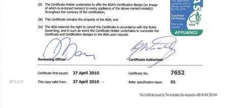
38 16 AGA Certification 38

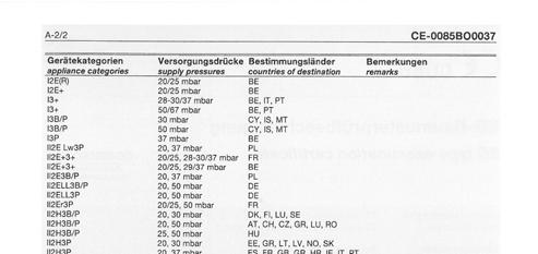
39 17 EC type examination certificate infraschwank D / calorschwank D - shape U 39
40 40
infraschwank D / calorschwank D
 - infraschwank D / calorschwank D Radiant Tube Heater 15 U / 20 U / 30 U / 40 U with single-, two-stage or modulating operation Technical Manual AGA Certificate 7652 0085BO0037 Technical Instructions Operating
U tube models PTU 09, 12, 15, 25, 30, 35, 40, 45. single linear tube models PTS 09, 12, 15, 25, 30, 35, 40, 45
 U tube models PTU 09, 2, 5, 25, 30, 35, 40, 45 & single linear tube models PTS 09, 2, 5, 25, 30, 35, 40, 45 installation, servicing & operating instructions INSTALLATION, SERVICING AND OPERATING INSTRUCTIONS
IDE 20 / IDE 30 / IDE 50 IDE 60 / IDE 80
 IDE 20 / IDE 30 / IDE 50 IDE 60 / IDE 80 EN OPERATING MANUAL OIL HEATER TRT-BA-IDE20-30-50-60-80-TC-001-EN Table of contents Information on the use of this manual... 1 Scope of delivery... 1 General safety...
BENSON LINEAR RADIANT TUBE
 BENSON LINEAR RADIANT TUBE Natural or Propane (Gas fired) I N S T A L L A T I O N C O M M I S S I O N I N G S E R V I C I N G U S E R I N S T R U C T I O N S September 2001 CONTENTS Page Compliance Notices
The Tube Heater Principle
 The Tube Heater Principle Innovative and Energy-saving Industrial Heating Innovative and Energy-saving Industrial Heating The tube heater technology Radiant tube heaters are gas-fired infrared heating
ASSEMBLY INSTRUCTIONS - NXS SERIES. INFRARED RADIANT TUBE HEATER Single and Two Stage Pull Through System (Negative Pressure)
") ASSEMBLY INSTRUCTIONS - NXS SERIES OWNER / INSTALLER: For your safety this manual must be carefully and thoroughly read and understood before installing, operating or servicing this heater. INFRARED RADIANT
ASSEMBLY INSTRUCTIONS - NXS SERIES OWNER / INSTALLER: For your safety this manual must be carefully and thoroughly read and understood before installing, operating or servicing this heater. INFRARED RADIANT
tungsten Smart-heat electric heater
 tungsten Smart-heat electric heater BY BROMIC Installation, instruction and service manual SUITABLE FOR electric HEATER MODELS: tungsten 2000w, 3000W, 4000W- AND tungsten 6000w Version 1.5 USA! IMPORTANT
INSTALLATION, INSTRUCTION AND SERVICE MANUAL
 TUNGSTEN SMART-HEAT ELECTRIC HEATER BY BROMIC INSTALLATION, INSTRUCTION AND SERVICE MANUAL SUITABLE FOR ELECTRIC HEATER MODELS: TUNGSTEN 2000W, 3000W, 4000W- AND TUNGSTEN 6000W Version 1.7 USA! IMPORTANT
Outdoor Tabletop Heater TTH20 Series
 Outdoor Tabletop Heater TTH20 Series FEATURES: The ideal solution for extending the outdoor entertaining season Creates a stylish and attractive ambience Casts an approximate 1 to 1.5 metre circle of radiant
OPTIMA RADIANT TUBE HEATING SYSTEMS. Operation, maintenance and servicing manual
 OPTIM RDINT TUBE HETING SYSTEMS Operation, maintenance and servicing manual CONTENTS GENERL INSTRUCTIONS Section Title Page 1. Preparing the Installation 4 2. Checking the Installation rea 5 3. Flue Connection
Servicing manual. Wall-mounted condensing gas boiler 600 Series - 11S / 19S / 24S / 24C /2002 GB(EN) For trade use
 For trade use") GB122 7210 1300-12/2002 GB(EN) For trade use Servicing manual Wall-mounted condensing gas boiler 600 Series - 11S / 19S / 24S / 24C Please read thoroughly before attempting to diagnose fault List of contents
GB122 7210 1300-12/2002 GB(EN) For trade use Servicing manual Wall-mounted condensing gas boiler 600 Series - 11S / 19S / 24S / 24C Please read thoroughly before attempting to diagnose fault List of contents
Servicing manual. 600 Series - 11S / 19S / 24S / 24C. Wall-mounted condensing gas boiler. For trade use
 GB122 Servicing manual Wall-mounted condensing gas boiler 600 Series - 11S / 19S / 24S / 24C For trade use Please read thoroughly before attemting to diagnose fault 7217 4900 (03/2010) GB/IE List of contents
Patio Heater Model No. GM and GM
 Patio Heater Model No. GM124-003 and GM124-004 FEATURES: The ideal solution for extending the season for outdoor entertaining Maximum output 39.6 MJ/hr Direct ignition Adjustable heat output Safety tip-over
Safety. Operating instructions Ionization pilot burners ZAI, ZMI, ZKIH DANGER. Contents WARNING CAUTION Edition 12.11
 050560 Edition. D F NL I E DK S N P GR TR CZ PL RUS H www.docuthek.com Operating instructions Ionization pilot burners,, Translation from the German 0 Elster GmbH Contents Checking the usage.....................
tungsten Smart-heat electric heater
 tungsten Smart-heat electric heater BY BROMIC Installation, instruction and service manual SUITABLE FOR electric HEATER MODELS: tungsten 2000w, 3000W, 4000W- AND tungsten 6000w Version 1.4 USA! IMPORTANT
INSTALLATION AND OPERATION INSTRUCTIONS OVERHEAD RADIANT TUBE HEATERS
 INSTALLATION AND OPERATION INSTRUCTIONS OVERHEAD RADIANT TUBE HEATERS Models: ADU5, ADU30, ADU35, ADU40, ADU45, ADL5, ADL30, ADL35, ADL40, ADL45 Single Stage Pull Through System (Negative Pressure) 0086
INSTALLATION AND OPERATION INSTRUCTIONS OVERHEAD RADIANT TUBE HEATERS
 INSTALLATION AND OPERATION INSTRUCTIONS OVERHEAD RADIANT TUBE HEATERS Models: PTUL 5, PTUL 0, PTUL 5, PTUL 0, PTUL 5, PTSL 5, PTSL 0, PTSL 5, PTSL 0, PTS L5 Single Stage Pull Through System (Negative Pressure)
Operating instructions
 Operating instructions Capriz 2 24c 28c GB, IE Contents Contents 1 Safety... 3 1.1 Action-related warnings... 3 1.2 Intended use... 3 1.3 General safety information... 4 2 Notes on the documentation...
ATMOSPHERIC GAS BOILER INSTALLATION, OPERATING AND MAINTENANCE MANUAL
 STREBEL GENEVA CE ATMOSPHERIC GAS BOILER INSTALLATION, OPERATING AND MAINTENANCE MANUAL INDEX TABLE 1 TECHNICAL DATA SECTION 1 SECTION 2 SECTION 3 SECTION 4 SECTION 5 SECTION 6 SECTION 7 SECTION 8 SECTION
Light oil burners. One stage operation
 Installation, use and maintenance instructions Light oil burners One stage operation CODE MODEL TYPE 3505 RDB CF 38 50 T3 350050 RDBR CF 6 50 TR 35050 RDBR CF 33 50 TR 35050 RDBR CF 38 50 T3R 350650 RDBR
INSTALLATION AND OPERATION INSTRUCTIONS OVERHEAD RADIANT TUBE HEATERS
 INSTALLATION AND OPERATION INSTRUCTIONS OVERHEAD RADIANT TUBE HEATERS Models: LRU5, LRU5, LRU0, LRU5, LRU0, LRU5, LRL5, LRL5, LRL0, LRL5, LRL0, LRL5 Single Stage Pull Through System (Negative Pressure)
MULTIPLEX SELF RECUPERATIVE gas burner
 Installation - Maintenance MULTIPLEX SELF RECUPERATIVE gas burner SERIES MPSR The Nu-way Multiplex Recuperative System offers the alternative of a self-recuperative burner or a separate recuperator and
Line Pressure ( w.c.) Gas Supply Min. Max. Pressure ( w.c.) Natural Gas Propane Gas
 Gas Supply Min. Max. Pressure ( w.c.) Natural Gas Propane Gas") HVAC Guideline Specifications WHISPER-JET: SET SERIES Two Stage Positive Pressure Gas-Fired Infrared Radiant Tube Type Heater Commercial/Industrial Applications Technical Summary Input Range: 80,000/60,000
HVAC Guideline Specifications WHISPER-JET: SET SERIES Two Stage Positive Pressure Gas-Fired Infrared Radiant Tube Type Heater Commercial/Industrial Applications Technical Summary Input Range: 80,000/60,000
SHORT WAVE INFRARED PANEL DRYER
 INSTRUCTIONS FOR: SHORT WAVE INFRARED PANEL DRYER MODEL: IR3000 Thank you for purchasing a Sealey product. Manufactured to a high standard this product will, if used according to these instructions and
INSTALLATION, INSTRUCTION AND SERVICE MANUAL
 COBALT SMART-HEAT ELECTRIC HEATER BY BROMIC INSTALLATION, INSTRUCTION AND SERVICE MANUAL SUITABLE FOR ELECTRIC HEATER MODELS: COBALT 2000W, 3000W, 4000W- AND COBALT 6000W Version 1.0 USA! IMPORTANT READ
Installation Manual. For Australian refrigerator models: N304M.3 (93 liter 3-way operation with LP gas, 240 volts AC, or 12 volts DC )
") Installation Manual For Australian refrigerator models: N304M.3 (93 liter 3-way operation with LP gas, 240 volts AC, or 12 volts DC ) N404M.3 (128 liter 3-way operation with LP gas, 240 volts AC, or 12
Installation Manual For Australian refrigerator models: N304M.3 (93 liter 3-way operation with LP gas, 240 volts AC, or 12 volts DC ) N404M.3 (128 liter 3-way operation with LP gas, 240 volts AC, or 12
Parts Available from
 Montage und Bedienungsanleitung Manuel d entretien Installation, use and maintenance instructions Installatie-, gebruiks- en onderhoudsvoorschriften Oδηγίες εγκατάστασης, χρήσης και συντήρησης D F GB NL
Propane Heater REMKO PGM 30 REMKO PGM 60
 Propane Heater REMKO PGM 30 REMKO PGM 60 Operation Technology Spare Parts Edition GB L07 REMKO strong as a bear. Operating instructions Make sure to read these instructions carefully before starting/using
INFRARED IP55 HEATER INSTRUCTIONS FOR: MODEL:- QZWP45N 1. SAFETY INSTRUCTIONS
 INSTRUCTIONS FOR: INFRARED IP55 HEATER MODEL:- QZWP45N Thank you for purchasing a Consort Claudgen product. Manufactured to a high standard this product will, if used according to these instructions and
Oil burners Brûleurs fioul Stookoliebranders
 Installation, use and maintenance instructions Manuel d entretien Installatie-, gebruiks- en onderhoudsvoorschriften GB F NL Oil burners Brûleurs fioul Stookoliebranders One stage operation Fonctionnement
INSTALLATION AND OPERATION INSTRUCTIONS Double Linear OVERHEAD RADIANT TUBE HEATERS Models: PTDSL 15, PTDSL 25, PTDSL 30, PTDSL 35, PTDSL 40, PTDSL 45
 INSTALLATION AND OPERATION INSTRUCTIONS Double Linear OVERHEAD RADIANT TUBE HEATERS Models: PTDSL 15, PTDSL 25, PTDSL 30, PTDSL 35, PTDSL 40, PTDSL 45 Single Stage Pull Through System (Negative Pressure)
terrasschwank+ 4A Technical Manual NL (English) Patio gas-infrared-heater 0085BR0505 terrasschwank+ 7/2A with housing
 Patio gas-infrared-heater 0085BR0505 terrasschwank+ 7/2A with housing") Patio gas-infrared-heater terrasschwank+ 4 terrasschwank+ 4A terrasschwank+ 7/2A (manual control) (single-stage automatic control) (two-stage automatic control) terrasschwank+ 7/2A with housing NL (English)
Patio gas-infrared-heater terrasschwank+ 4 terrasschwank+ 4A terrasschwank+ 7/2A (manual control) (single-stage automatic control) (two-stage automatic control) terrasschwank+ 7/2A with housing NL (English)
JUMBO INDIRECT FIRED DIESEL HEATER OPERATING INSTRUCTIONS
 JUMBO INDIRECT FIRED DIESEL HEATER OPERATING INSTRUCTIONS Before using the heater, read and understand all instructions and follow them carefully. The manufacturer is not responsible for damages to goods
Operating instructions
 The energy you need Operating instructions Betacom 3 24c -A (H-GB) 30c -A (H-GB) GB, IE Contents Contents 1 Safety... 3 1.1 Action-related warnings... 3 1.2 Intended use... 3 1.3 General safety information...
Herringbone Linked Flue System
 Herringbone Linked Flue ystem INTALLATION, ERVICING AND OPERATING INTRUCTION CBU09//5-HB, RU(ERU)5-HB, RU30/35/40/45-HB RL09//5-HB,RL5-HB, RL30/35/40/45-HB Gas Fired Products (UK) Ltd. Chapel Lane, Claydon,
HERRINGBONE HB COMBINED FLUE SYSTEM
 HERRINGBONE HB COMBINED FLUE SYSTEM Index 1 2 3 4 5 6 7 General arrangement of Ambi-Rad Herringbone system Instructions and installation Manifold assembly Fan to flue arrangement Commissioning Control
MAINTENANCE AND SERVICE GUIDE
 c Dimensions MAINTENANCE AND SERVICE GUIDE System II 80 and 100 Central Heating Fanned Flue Boiler Sizes in mm Flue types: C 12 or 42: horizontal C 32 xx: vertical concentric C 32 xy: Twin flue Boiler
User Manual. 600mm, 700mm & 900mm Gas Cooktops Model No. CF6GS, CF6GW, CF7GS, CF9GS
 User Manual 600mm, 700mm & 900mm Gas Cooktops Model No. CF6GS, CF6GW, CF7GS, CF9GS For all product enquires, including warranty support, please contact our Customer Care team 1800 444 357 or email customercare@hapl.com.au
SIME FORMAT WALL HUNG BOILERS MODEL 34i AND MODEL 34e. cod A
 cod. 6272262A GENERAL DATA Heating Data Heat Output Input (Adjustable) (Adjustable) Format 34i 11.2 34KW 45 145MJ/hr Format 34e 11.2 34KW 45 145MJ/hr General Specifications FORMAT 34i 34e Main burner injectors
TC MODULE (FFD) (with Gas Hob)
 (with Gas Hob)") TC MODULE (FFD) (with Gas Hob) Installation Instructions REMEMBER: when replacing a part on this appliance, use only spare parts that you can be assured conform to the safety and performance specification
TC MODULE (FFD) (with Gas Hob) Installation Instructions REMEMBER: when replacing a part on this appliance, use only spare parts that you can be assured conform to the safety and performance specification
e Bath Fan with Light User s Guide
 e Bath Fan with Light User s Guide abfl100rnl, BFL125RNL Item Stock Number(s): BFL100RNL, BFL125RNL IMPORTANT INSTRUCTIONS - OPERATING MANUAL READ AND SAVE THESE INSTRUCTIONS READ CAREFULLY BEFORE ATTEMPTING
DH-Direct Fired Poultry Farm Diesel Heater
 DH-Direct Fired Poultry Farm Diesel Heater Comparison of Diesel Heater to Gas Heater Diesel LPG Gas LPG Gas KW 43 70 120 Fuel consumption/hr 3 5.1 8.8 Heat output 37000 60000 100000 Cost of fuel/lit or
INSTALLATION, OPERATING AND SERVICING INSTRUCTIONS BG 2000-S (V13) RU PL DE IT ES NL EN 1 662Y0600 A
 RU PL DE IT ES NL EN 1 662Y0600 A") INSTALLATION, OPERATING AND SERVICING INSTRUCTIONS G 2000-S 25-35 - 45-55 60-70 - 100 (V13) 1 Index WARNINGS GAS FLOW RATE DIMSIONS SETTINGS PARAMETERS SERVICING THE URNER 3 8 13 OPERATING DESCRIPTION
INSTALLATION, OPERATING AND SERVICING INSTRUCTIONS G 2000-S 25-35 - 45-55 60-70 - 100 (V13) 1 Index WARNINGS GAS FLOW RATE DIMSIONS SETTINGS PARAMETERS SERVICING THE URNER 3 8 13 OPERATING DESCRIPTION
HX Field Replacement Kit
 Quantity Kit Part Number Description PE 110 Natural Gas Stainless Steel Condensate Pan PT 110 Natural Gas Polypropylene Condensate Pan Model PE 110 LP Stainless Steel Condensate Pan PT 110 LP Polypropylene
DMG 973. Gas Burner Safety Control. For 2-stage forced draught and combi oil/gas burners, facility to connect an air damper unit
 A Honeywell Company Gas Burner Safety Control For 2-stage forced draught and combi oil/gas burners, facility to connect an air damper unit Possible flame detectors: - Ionisation probe - Infrared flicker
Light oil / kerosene burner
 Installation, use and maintenance instructions Light oil / kerosene burner One stage operation CODE MODEL TYPE 374445 G5 444T50 290238 (5) - 05/20 TECHNICAL DATA Thermal power output 28 60 kw 2.3 5 kg/h
Light oil - kerosene burner
 Installation, use and maintenance instructions Light oil - kerosene burner One stage operation CODE MODEL TYPE 374374 G3B 437T 90 (4) - 05/0 TECHNICAL FEATURES TYPE 437T Thermal power output 9 35 kw.6
Installation and maintenance instructions
 6304 4995 0/004 GB For installer Installation and maintenance instructions Flue gas heat exchanger WT50/60 Please read thoroughly prior to installation and maintenance. Summary About this manual This equipment
Installation Manual EF5000 AUS & NZ
 Installation Manual EF5000 AUS & NZ This manual is ONLY for fires with a serial No. from 80600 to 80999. Important: The appliance shall be installed in accordance with; Local gas fitting regulations Municipal
Pizza Oven with Stand
 Pizza Oven with Stand Cooks up to 3 pizzas at a time Use to cook a variety of food Easy clean vitreous enamel interior Model No. P0104 Powerful 22MJ/h stainless steel burner Viewing window and temperature
TERRACE AND PATIO HEATER HLB-2400/ 2650 SERIES
 TERRACE AND PATIO HEATER HLB-2400/ 2650 SERIES INSTALLATION AND OPERATION GUIDE INDEX General and specifications 1 Security and caution.. 1,2 Tools and accessories required 2 Assembly instructions 3 Verifying
Gas Instantaneous Water Heater
 6 720 607 823 GB (06.06) SM Installation and Operating Instructions Gas Instantaneous Water Heater WR10..B... WR11..B... With electronic ignition and triple safety system consisting of ionisation detector,
Operating instructions
 Operating instructions For the operator Operating instructions HOME SYSTEM GB, IE Publisher/manufacturer Vaillant GmbH Berghauser Str. 40 D-42859 Remscheid Tel. +49 21 91 18 0 Fax +49 21 91 18 28 10 info@vaillant.de
HG 675 CX 60 HG 675 CN 60 HG 675 CW 60
 HG 675 X 60 HG 675 CX 60 HG 675 CN 60 HG 675 CW 60 1 2 1. : 93/68: 90/396: 2006/95/CE: 2004/108/CE: - 1935/2004:. 2002/95/CE: RoHS 2.,.,,,,...,. (,..)..,,.,. ( ),,, ;,,.,.....,.,,,,,,...,. (..),,.,..,.,,,,
Corn Flame Energy Corn Stove Model 3000
 Corn Flame Energy Corn Stove Model 3000 Installation and Operation Guide Read thoroughly before starting installation Save this manual for future reference SAFETY NOTICE If this stove is not properly installed,
SOUND-INSULATED FAN. Iso-K OPERATION MANUAL. Iso-K_v.1(2)-EN.indd :20:59
-EN.indd :20:59") SOUND-INSULATED FAN OPERATION MANUAL _v.1(2)-en.indd 1 10.08.2015 15:20:59 CONTENT Introduction 3 General 3 Safety rules 3 Transport and storage requirements 3 Manufacturer's warranty 3 Fan design 4 Delivery
SOUND-INSULATED FAN OPERATION MANUAL _v.1(2)-en.indd 1 10.08.2015 15:20:59 CONTENT Introduction 3 General 3 Safety rules 3 Transport and storage requirements 3 Manufacturer's warranty 3 Fan design 4 Delivery
Installation Instructions Use and Care Guide Instructions d installation Mode d emploi et d entretien
 Installation Instructions Use and Care Guide Instructions d installation Mode d emploi et d entretien AMCHD36SS/ AMCHD44SS/ INDEX WARNINGS AND REQUIREMENTS... 3 RECOMMENDATIONS AND SUGGESTIONS... 6 DIMENSIONS
AMBIRAD VISION VS RANGE RADIANT TUBE HEATERS SERVICING & COMMISSIONING MANUAL
 Instruction Manual. AMBIRAD VISION VS RANGE RADIANT TUBE HEATERS SERVICING & COMMISSIONING MANUAL Note: For use with all Vision VS models with Generation codes AA & AB. (also for burners fitted with SIT
Model No: Little Devil II (inc ss)
") GAS HEATER Model No: Little Devil II (inc ss) PART NO: 6926020, 6926025 (SS) OPERATION & MAINTENANCE INSTRUCTIONS LS1213 INTRODUCTION Thank you for purchasing this CLARKE Gas Heater. Before attempting
GAS HEATER Model No: Little Devil II (inc ss) PART NO: 6926020, 6926025 (SS) OPERATION & MAINTENANCE INSTRUCTIONS LS1213 INTRODUCTION Thank you for purchasing this CLARKE Gas Heater. Before attempting
INSTRUCTION MANUAL FOR OIL BURNER MODELS
 INSTRUCTION MANUAL FOR OIL BURNER MODELS X500-2 Low voltage 12v dc Brushed motor E90-803-001-005-01 Rev 4-1 - Contents Technical specifications Technical data...3 Working field...3 Dimensions...4 Head
INSTALLATION GUIDE NZ AU E
 GAS COOKTOP CG604DX & CG905DX models INSTALLATION GUIDE NZ AU 590447E 08.17 1 SAFETY AND WARNINGS Electrical shock hazard WARNING! Before carrying out any work on the electrical section of the appliance,
1.03 DELIVERY, STORAGE, AND HANDLING Heater will be stored to secure against damage and handled per manufacturer s recommendations.
 HVAC Guideline Specifications supraschwank Packaged Luminous Infrared Radiant Gas Heater Combined Intensity (produces both Low and High Intensity radiant output) Commercial/Industrial Applications Size
Mikrofill Ethos Condensing combination boiler. Maintenance Instructions 24cc
 Mikrofill Ethos Condensing combination boiler Maintenance Instructions 24cc IMPORTANT Benchmark Installation, Commissioning and Service Record Log Book is enclosed in your customer information pack. This
Proline GAS HOB Model TCG40IX Instruction Book
 Proline GAS HOB Model TCG40IX Instruction Book GB Operating and Installation Instructions Index Technical data and specifications...... 3 Installation...................... 3-6 Ventilation........................
ASSEMBLY, INSTALLATION & SERVICING MANUAL FOR AMBIRAD VISION VSX RANGE OF RADIANT TUBE HEATERS
 ASSEMBLY, INSTALLATION & SERVICING MANUAL FOR AMBIRAD VISION VSX RANGE OF RADIANT TUBE HEATERS INDEX Section Introduction and Document Index Installation Requirements -------------------------------------------------1
Operating Instructions
 Operating Instructions Varioset Standard After-sales service For after-sales service please contact the Veit representative in your country. GmbH & Co. Justus - von - Liebig - Str. 15 D - 86899 Landsberg
Contents authorised persons
 Contents 1. INSTRUCTIONS FOR SAFE AND PROPER USE 4 2. POSITIONING OF THE HOB 6 3. GAS CONNECTION 10 4. ELECTRICAL CONNECTION 11 5. ADAPTATION TO DIFFERENT TYPES OF GAS 12 6. FINAL OPERATIONS 14 7. USING
INSTRUCTION MANUAL FOR OIL BURNER MODELS
 INSTRUCTION MANUAL FOR OIL BURNER MODELS X500 Bio B10 E90-803-001-001-00 Rev 7-1 - Contents Technical specifications Technical data... 3 Working field... 3 Dimensions... 4 Head and electrode settings...
Remeha. Fuel oil/gas boilers P 520. Installation and Service Manual A
 Remeha Fuel oil/gas boilers EN Installation and Service Manual 300016859-001-A 63115 Declaration of conformity The appliance complies with the standard model described in declaration of compliance. It
INSTRUCTION MANUAL FOR OIL BURNER MODELS
 INSTRUCTION MANUAL FOR OIL BURNER MODELS X400 Bio B10 E90-803-001-001-03 Rev 13-1 - Contents Technical specifications Technical data... 3 Working field... 3 Dimensions... 4 Head and electrode settings...
HOT AIR GENERATOR WITH GAS BURNER NA11.45 A GGS. Installation Operation Commissioning Maintenance
 Installation Operation Commissioning Maintenance HOT AIR GENERATOR WITH GAS BURNER GGS NA11.45 A 06-2011 04-2011 CONTENTS 1. DESCRIPTION OF THE UNIT 2. INSTALLATION & CONNECTION 3. COMMISSIONING 4. CARE
F900 SERIES GAS CHARGRILL G9440, G9460, G9490, G User, installation and servicing instructions T Read these instructions before use
 F900 SERIES User, installation and servicing instructions GAS CHARGRILL G9440, G9460, G9490, G94120 Read these instructions before use DATE PURCHASED: MODEL NUMBER: SERIAL NUMBER: DEALER: SERVICE PROVIDER:
Operating instructions
 Operating instructions Gas condensing boiler WARNING: If the information in this manual is not followed exactly, a fire or explosion may result causing property damage, personal injury or loss of life.
INSTALLATION AND MANINTENANCE INSTRUCTIONS
 INSTALLATION AND MANINTENANCE INSTRUCTIONS Appr. Nr. A 9503 T - 0085 AQ 0765 PEGASUS F2 T HIGH EFFICIENCY GAS-FIRED CAST-IRON BOILERS Models 51-68 - 85-102 2 Contents 1. General technical data 2. Dimensional
Ecoboiler T20 & T30 SERVICE MANUAL. Marco Beverage Systems Ltd. 63d Heather Road, Sandyford Industrial Estate, Dublin 18, Republic of Ireland
 Ecoboiler T20 & T30 SERVICE MANUAL Marco Beverage Systems Ltd. 63d Heather Road, Sandyford Industrial Estate, Dublin 18, Republic of Ireland Ireland Tel: (01) 295 2674 Ireland Fax: (01) 295 3715 UK Tel:
Electronic Standard Devices. Annunciator Relay. MR 11 and MRE 11 MR 21 and MRE 21
 Electronic Standard Devices Annunciator Relay MR and MRE MR 2 and MRE 2 The products described in this brochure are intended for industrial use and meet the requirements laid down by the EU directive 7
ATM Lighting sp. z o.o
 INSTALLATION AND MAINTENANCE MANUAL FOR EXPLOSIONPROOF LIGHT FITTING EXL210LED Carefully read the instructions before mounting the light fitting. ATM Lighting sp. z o.o., ul. Budowlanych 31, 80-298 Gdańsk,
Mod. ANBR9..G. CR DOC. NO. GAS-HEATED TILTING BRATT PAN. INSTRUCTIONS FOR INSTALLATION, ADJUSTMENT, USE AND MAINTENANCE...
 -HEATED TILTING BRATT PAN Mod. ANBR9..G. INSTRUCTIONS FOR INSTALLATION, ADJUSTMENT, USE AND MAINTENANCE...page 2-5 APPENDIX....pagina 6-7 Read the manual thoroughly and keep it in a safe place throughout
Service Manual Model 3163
 Service Manual Model 3163 Contents Important Safety Information.......... 1 Specifications.................. 2 General Information.............. 2 Direct Vent Requirements........... 2 Propane System................
EUROBOX SERIES TYPES CM... SM... MM...
 EUROBOX SERIES TYPES CM... SM... MM... AUTOMATIC GAS BURNER CONTROL SYSTEMS FOR GAS BURNERS AND GAS BURNING APPLIANCES WITH OR WITHOUT FAN Application This range of electronic gas burner control systems
READ AND SAVE THESE INSTRUCTIONS
 READ AND SAVE THESE INSTRUCTIONS WARNING TO REDUCE THE RISK OF FIRE, ELECTRIC SHOCK, OR INJURY TO PERSONS, OBSERVE THE FOLLOWING: 1. Use this unit only in the manner intended by the manufacturer. If you
Operating instructions
 Operating instructions (Translation of the original operating instructions) Type TEKA FILTERCUBE-MV TEKA Absaug- und Entsorgungstechnologie GmbH Industriestraße 13 D-46342 Velen Postfach 1137 D-46334 Velen
SERVICE MANUAL. Ecoboiler Model range: T20 ( ) T30 ( )
 T30 ( )") SERVICE MANUAL Ecoboiler Model range: T20 (1000662) T30 (1000663) Marco Beverage Systems Ltd. 63d Heather Road, Sandyford Industrial Estate, Dublin 18, Republic of Ireland Ireland Tel: (01) 295 2674 Ireland
SERVICE MANUAL Ecoboiler Model range: T20 (1000662) T30 (1000663) Marco Beverage Systems Ltd. 63d Heather Road, Sandyford Industrial Estate, Dublin 18, Republic of Ireland Ireland Tel: (01) 295 2674 Ireland
An infrared electric heater blending aesthetics and function
 ELECTRIC An infrared electric heater blending aesthetics and function Witness the art of smart-heating with Bromic Heating s new Tungsten Smart-Heat Electric, an infrared electric heater blending aesthetics
24 VAC SYSTEM CONTROL KIT
 24 VAC SYSTEM CONTROL KIT Model: CK-91F and CK-91FG Designed for use with the SWG Series Power Venter for controlling Natural Gas or L.P. Gas draft induced appliances with a 24 VAC Gas Valve and a 30-millivolt
AMBIRAD VISION VS RANGE RADIANT TUBE HEATERS SERVICING & COMMISSIONING MANUAL
 Instruction Manual. AMBIRAD VISION VS RANGE RADIANT TUBE HEATERS SERVICING & COMMISSIONING MANUAL Note: For use with all Vision VS models with Generation codes AA, AB & AC. (also for burners fitted with
INSTALLATION AND USER S MANUAL COOKER HOOD RS-600/A-S
 INSTALLATION AND USER S MANUAL COOKER HOOD RS-600/A-S RS-600 (CHS60SS)-GB-05.indd 1 6/8/2010 9:30:59 AM TABLE OF CONTENTS 1. Introduction 2 2. Safety precaution 2 3. Intended use 3 4. Parts supplied 3
Installation Instructions Horizon Natural Draft Electronic Ignition Gas Fireplaces
 Installation Instructions Horizon Natural Draft Electronic Ignition Gas Fireplaces Installation Instructions Horizon Natural Draft Electronic Ignition 3 Sided Gas Fireplaces Natural Draft Electronic Ignition
GAS COOKTOP INSTALLATION INSTRUCTIONS
 INSTALLATION AND SERVICE MUST BE PERFORMED BY A QUALIFIED INSTALLER. IMPORTANT: SAVE FOR LOCAL ELECTRICAL INSPECTOR'S USE. READ AND SAVE THESE INSTRUCTIONS FOR FUTURE REFERENCE. WARNING If the information
RWC Issue: F. Description: ARISTON WALL CANOPY Model Numbers: ARCH90BIX. Model may vary slightly from images pictured. All measurements are in mm.
 RWC Issue: F Description: ARISTON WALL CANOPY Model Numbers: ARCH90BIX Model may vary slightly from images pictured. All measurements are in mm. 1 Overview Pre-installation Thank you for purchasing a quality
UV Flame Supervision System
 7 783 UV Flame Supervision System DETACTOGYR LFE50 Series 02 ISO 9001 The LFE50 is a self-checking UV flame supervision system designed for use with continuously operating burners or for burners running
1. GENERAL SAFETY RULES
 ID180 & ID290 Indirect-Fired Diesel/Oil Construction Heaters Sure Flame Products Lethbridge, Alberta, Canada Telephone: (403)328-5353 Fax: (403)328-9956 www.sureflame.ca July 12, 2006 Service and Maintenance
Instructions for use. Gas hobs for installation in worktops GKS GWS GKS GKS
 Instructions for use Gas hobs for installation in worktops GKS 3920.0 GWS 3911.0 GKS 6940.0 GKS 9951.0 For use in: Hong Kong Issue: 2014-01-14 Version: 1.3_EN Identity no.: 073587_HK Welcome 2 Welcome
Mechanical seals external, single or double, to DIN EN 12756
 INSTALLATION AND OPERATING MANUAL Translation of the original manual Series SCK Bearing pedestal group: 0 Mechanical seals external, single or Keep for future use! This operating manual must be strictly
WATLOW IND. WATROD Modular Duct Heater Installation & Maintenance Manual I&M NUMBER: Page: 1 Date:6/11/2008 Rev: 2
 I&M NUMBER: 316-42-15-1 Page: 1 _ Pre Installation Check to make sure that heater received is the same as that ordered. Elements may come in contact with each other during shipment. Minor adjustments to
Moisture inside the drum is due to final testing.
 Safety instructions Scope of delivery depending on model Moisture inside the drum is due to final testing. Removing the transport braces Water connection depending on model The washing machine is heavy
Flow switch. Operating Manual. English manual page Page 1 of 15 Fax:
 Operating Manual www.jlso-tec-trade.de Flow switch English manual page 1-15 Page 1 of 15 Flow switch Table of Contents Page 1 Device Description and Intended Use... 19 1.1 Flow switch version VH...X...
INSTALLATION GUIDE Dual Fuel Ranges
 INSTALLATION GUIDE Dual Fuel Ranges Contents Wolf Dual Fuel Ranges......................... 3 Safety Instructions............................ 4 Dual Fuel Range Specifications.................. 5 Dual Fuel
Installation, Operation and Service Instructions VARIOMAX. (one-stage) (two-stage) VARIOMAX 06 / 1 VARIOMAX 06 / 2 VARIOMAX 12 / 1 VARIOMAX 12 / 2
 (two-stage) VARIOMAX 06 / 1 VARIOMAX 06 / 2 VARIOMAX 12 / 1 VARIOMAX 12 / 2") Installation, Operation and Service Instructions VARIOMAX (one-stage) (two-stage) VARIOMAX 06 / 1 VARIOMAX 06 / 2 VARIOMAX 12 / 1 VARIOMAX 12 / 2 Read and thoroughly understand these instructions before
Installation, Operation and Service Instructions VARIOMAX (one-stage) (two-stage) VARIOMAX 06 / 1 VARIOMAX 06 / 2 VARIOMAX 12 / 1 VARIOMAX 12 / 2 Read and thoroughly understand these instructions before
Glass and Dishwashers AMX / AUX Series
 Glass and Dishwashers AMX / AUX Series INSTALLATION OPERATION VERSION 24.02.04 Important Notes Use in Accordance with Regulations This machine is exclusively to be used to wash ware such as plates, cups,