INSTALLATION, OPERATION AND MAINTENANCE. Bio burners kw
|
|
|
- Jonah Hancock
- 5 years ago
- Views:
Transcription


1 INSTALLATION, OPERATION AND MAINTENANCE Bio burners kw

2 TABLE OF CONTENTS For the new owner...3 Burner data...4 General...5 Shipping, handling and storage Contents of the BioJet burner delivery...8 Burner installation...9 Installation of the burner screw Installation of a pellet feeder...12 Installation of other equipment Back fire protection, connections...16 Connecting the BioJet burner to the boiler water circuit...17 Commissioning and adjustment Use of the burner...20 Maintenance Instructions for emergencies...24 Technical specification...25 Contents of the delivery Warranty...29
3 FOR THE NEW OWNER In this manual, we have gathered the essential information on installation, use and maintenance. Ariterm Oy devices are designed to be reliable, and the the back burning risk has been eliminated with several safety systems. By following the instructions in this manual, it is possible to achieve the best functionality for the HakeJet or BioJet bio burner. The easy use of the burner is also a function of the fuel quality. A safe and functional heating system saves money and user effort. The structure and equipment level of the burner is chosen already in the ordering phase to suit the needs of the customer. This manual is a general manual for the whole Ariterm Bio Burner product family. Because of this, there can be differences between the shipped burner and this manual when it comes to accessories. During installation, situations to which this manual does not give straight answers can arise.
4 BURNER DATA Write down the burner data in the table below. This makes it possible to act faster in maintenance and repair situations. Write the burner model, serial number, date of purchase and date of installation here. MODEL SERIAL NUMBER / YEAR DATE OF PURCHASE DATE OF INSTALLATION DESIGN FUEL INSTALLED BY 4
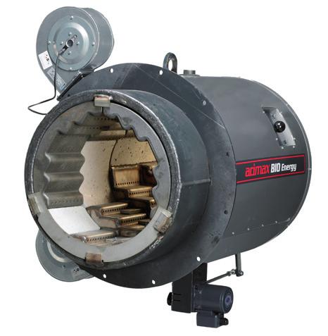
5 GENERAL Ariterm bio burners fulfil the modern usage and safety requirements of wood chip and pellet burning. The Biojet burner is a pipe-type burner that has a water-cooled housing. The Hakejet is halfopen and is air cooled. The fuel is fed into the burner via a screw. Inside the burner, the fuel is mixed with primary and secondary combustion air. The feeding system can consist of one or more feeding screws and a fuel storage. The screws and the fuel storage are chosen according to the fuel used. Systems with more than one feeding screw contain level sensors between the screws to control and maintain a steady fuel flow to the burner. The automation also controls the walking floor silo if installed. The burner grates are made from durable cast iron or fire proof steel (T). The water-cooled housing of the Biojet burner is connected to the water circuit of the boiler. Its maximum pressure class is 4 bar. The equipment is controlled by burner automatics according to the signal from the boiler sensor. The automation logic vary depending on the chosen automatics. With the basic automatics, the burner operates on the operating phase and resting phase principle. With the stepless power control automatics the burner power depends on the boiler power output. The burner can operate continuously on partial output, in which case the resting phase is in operation only when the output requirement is below minimum. The burner needs to be equipped with a back burning protection. This protective equipment varies according to the chosen fuel and feeding system. Note that the chosen fuel also affects the whole system composition. ALWAYS CHECK WITH THE PRODUCT SUPPLIER THAT THE FUEL USED IS SUITABLE FOR THE BURNER! 5


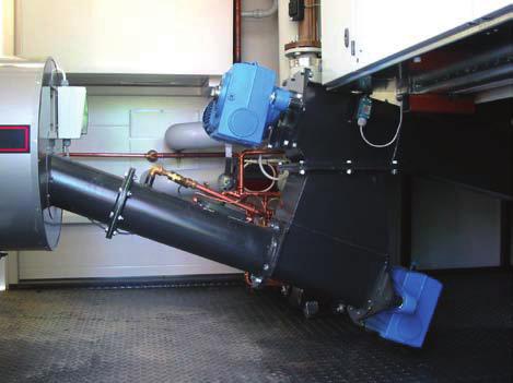
6 SHIPPING, HANDLING AND STORAGE The parts of the burner are packaged in the factory for shipping and short-time storage. However, depending on shipping method and storage, the packages may need extra protection against moisture, battering etc. Picture shows a Hakejet burner with an T2 fuel storage In case you are transporting the bio burner system yourself, it is important to fasten the packages to each other and to the transporting vehicle to avoid damage to the equipment and to uphold traffic safety. The driver is responsible for the correct loading and fastening of the equipment. When handling the burner parts, it is recommended to be careful in order to avoid damage. The burner can be lifted either fastened to the shipping platform or from the hoisting bracket above the burner. The burner parts can be stored outdoors if they are shielded from damp earth and rain. For a long storing period, a better storage space is needed. It is recommended to store the equipment indoors because it contains sensitive parts like electric motors, sensors and the control centre. Ariterm bio burners come in two different models HakeJet kw GRRH cast iron grates ceramic burning chamber 2 fans wood chips and pellets BioJet kw GRRH cast iron grates ceramic burning chamber 2-4 fans wood chips, wood pellets and briquettes, kw only wood pellets 6
7 Reception and handling When receiving the shipment, check that the contents of the delivery match your order and the included final inspection report and equipment list. In uncertain cases, contact Your dealer. Before starting the installation, it is necessary to read not only this installation and operation manual, but also the installation manuals for the boiler, the automatics and a possible fuel storage. This way, you can be sure that the measurements and all the other things that are critical for the successful completion of the installation are in order. The Ariterm bio burner parts must always be installed professionally and according to the requirements. Recommended installation order: 1. Burner is installed into the boiler which is in its final place. Do not connect piping or flue duct. 2. Place the fuel storage in its final place. 3. Install the fuel feeding screws between the burner and the storage. 4. Adjust the boiler and/or the fuel storage so that the screw connections fit together. 5. Fasten the components and finish the installation with pipe and electrical installations. Requirements for Installation and Operating Environment The boiler room must be constructed according to the relevant regulations in the destination country Installation and operating temperature C Combustion air intake to the boiler room. Recommended area 5 cm 2 / installed kw The moisture content of the boiler room air % (to prevent moisture condensation) Required Connections Electric feed via automation cabinet Connecting the cooling circuit of the BioJet burner to the boiler A chimney duct, according to the boiler requirements Water for the automatic extinguishing system. With pellet, a dry powder installation is recommended Space Requirement Note that there needs to be room for both the burner and the burner screw between the boiler and the boiler room wall. A distance of at least one metre between the boiler and the wall is recommended for the sides on which sooting and maintenance tasks will be done. Please take into account that for service reasons the burner can be unfastened. Also take into account feeding screws and replaceability and door openings. 7
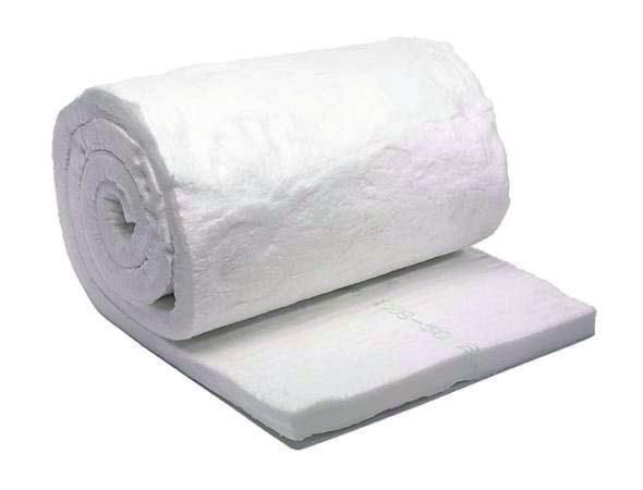
8 CONTENTS OF THE BIOJET BURNER DELIVERY MODEL Nro. Part HakeJet BioJet 1 Silicon pipe, heat resistant X X 2 Sealing ring (plate) 3 Ceramic wool 50x80x600mm2 pcs Cover plate X X fans X X 7 Limit switch (transition limit) X X 8 Limit switch fastener X X 9 Limit switch striking plate X X 10 Condensator box (1-phase fans only) X X 11 Bag of screws X X 12 Cleaning tool X X 13 Secondary air fan duct X X 14 Overheat protector X X A burner delivery normally comes with a burner screw, screw motor, automation and storage. They are chosen according to the used fuel and the type of the fuel storage. Images of parts in the delivery are at the end of this manual. 8
 in the fire chamber the chimney must be according to boiler requirements or be equipped with a flue gas fan.")
9 BURNER INSTALLATION The burner can be installed into a solid fuel boiler that has a power range equivalent to the output of the burner. To ensure a correct under pressure (25-30 Pa) in the fire chamber the chimney must be according to boiler requirements or be equipped with a flue gas fan. This instruction covers the BioJet burner and the HakeJet burner. Note that all instructions do not apply to the HakeJet burner. The burner is connected to the boiler with bolts and the seam is sealed with heat-resistant silicone (1). The connection seam has to be sealed well. No air may leak out! If the burner opening of the boiler is square, a fitting flange (accessory) must be used. The BioJet burner is water cooled and shall be connected to the boiler water circulation. The burner s overheating shield shall be connected to a DN 15 t-branch installed into the pipe ascending from the top of the burner (see picture). The shield stops the system in case there is a malfunction in the burner cooling for some reason. A pump ( see table on page 16) is installed into the return pipe. If shutter valves are installed into the circulation, the handles must be removed. See the installation chart on page 17. 9
10 INSTALLATION OF THE BURNER SCREW The burner screw shall be attached to the burner. The burner screw is usually installed after the burner is installed. 1. Insert the sealing ring (2) into the burner. Do not fasten yet. 2. Wood chip systems: Assemble the screw and the drop funnel and attach the drop funnel to the fuel storage flange. The burner screw insertion should be appr. 15 mm. Adjust the insertion by moving the boiler. Pellet systems: Assemble the burner screw leg and place the screw into the burner hole. Do not mount the screw too steep as this will cause fuel to pile in the burner. 3. Fit the centering sealing ring (2) on the burner screw so that it stays against both the burner and the burner screw as tightly as possible. Position the screw as low as possible in the opening. Attach the ring to the screw pipe by tack welding. NOTE! The burner is a pressure vessel. Avoid attaching the plate into it. HINT: A temporary handle can be welded onto the ring to make installation easier. 4. Seal the gap with ceramic wool. The sealing work must be done with care. 5. Align the cover plates (5) around the burner screw and fasten them with plate screws (11). 6. A drive motor and reduction gear are installed at the end of the feeding screw. Gear positions are described at the end of the manual. Picture shows a wood chip screw. 2 10
11 INSTALLATION OF THE BURNER SCREW 11


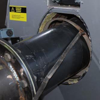
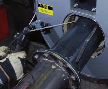
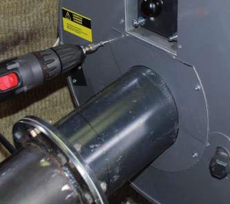
12 INSTALLATION OF A PELLET FEEDER The burner screw can be replaced by a PS-10 pellet feeder when using wood pellets. It has a built-in cell feeder and a level sensor to control the silo screw(s). The pellet feeder gives a more steady fuel flow compared to the traditional system. PS-10 contains a back fire thermostat. It also has an extra back fire safety device. PS-10 installed against a BJ700 burner. Back fire thermostat and transition limit switch installed. The PS-10 is installed in the same manner as the traditional burner screw. 12
 in order to prevent combustion gases to flow in the wrong direction. 2.")
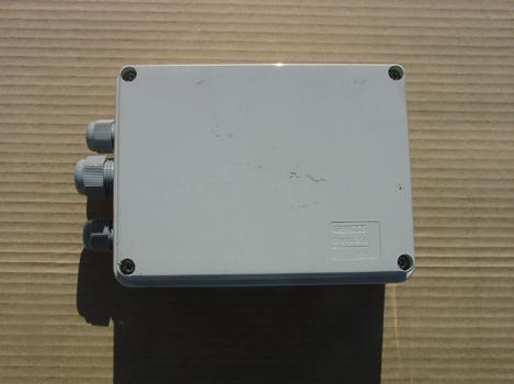
. Finally, install the limit switch striking plate (9). 3. Install the condensator box (10) to a suitable location.")
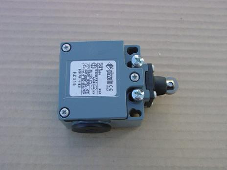
13 INSTALLATION OF OTHER EQUIPMENT 1. Two combustion air fans (6) are included in the burner delivery (BJ pcs, BJ pcs). Install the fans so that the incoming air is not disturbed. An extra air duct belongs to the secondary air fan (the upper) in order to prevent combustion gases to flow in the wrong direction. 2. The limit switch (7) is installed between the burner and the burner screw so that the switch cuts off the power in case of a transition between the screw and the burner. The switch is attached with the aid of a limit switch fastener (8). Finally, install the limit switch striking plate (9). 3. Install the condensator box (10) to a suitable location. Avoid places where the box would be exposed to heat or mechanical shock. Only 1-phase fans. The burner pictured is a BioJet with combustion air fans, limit switch, condensator boxes, back fire thermostat and pulse operated back fire protection. 13


14 INSTALLATION OF OTHER EQUIPMENT Electric Assembly Wiring diagrams are delivered with the chosen automation. Changes and additions made on site which require updating of diagrams are notariterm s responsibility unless otherwise agreed. THE ELECTRIC ASSEMBLY MUST BE DONE BY A PROFESSIONAL ELECTRICIAN. Installation of the Safety System to prevent backfire The Ariterm Bio burners need to be equipped with a sufficient safety system to protect it from backburning. To make the operation of the system safe, it is important to have all the extinguishing systems installed before the burner is started. The systems consist of the following (a-e): See pattern on page 11. a. AVTA safety valve, to be connected to the water supply network (wood chips): - A Danfoss AVTA 15 ( C) thermostat valve (3) is connected to the burner screw pipe and drop funnel (in a 2-screw system). The valve sensor is pushed into the sensor pocket (see image) and the valve is connected to the water supply network. To avoid the possible loss of network pressure, an expansion tank (SS) with a back-pressure valve (4) and an alarm pressure gauge (PIA) can be installed. - After the manual bypass has been installed, water can also be sprayed into the fuel system manually. - The AVTA valve is adjusted to the temperature of approximately 85 C. - Note the installation instructions of the valve sensor! The backfire thermostat sensors and the AVTA valve are installed into their own sensor pockets on the surface of the feeding pipe. Note that the sensor needs to be set tightly against the screw pipe box. If necessary, use a heat conductive adhesive mass or a tightening screw. The screw must not damage the sensor! The backfire thermostat is connected to the burner automatics. AVTA functions with pressurised water b. Pulse operated extinguishing system, to be connected to the water supply network: - The pipe of the magnetic valve (5) is connected to the feeding screw pipe. The valve is controlled by a pulse-controlled backburning protector (6). The backburning protection is adjusted to a temperature of appr. 80 C so that it will start to operate before the AVTA valve. - The operation of the magnetic valve during a power failure can be assured with an UPS (7). - To avoid the possible loss of network pressure, an expansion tank with a back-pressure valve (4) and an alarm pressure gauge (PIA) can be installed. - When used with pellets use only short settings (0,1-0,5 s) A pulse operated backfire protection can be delivered as an accessory. The sensor is installed closest to the burner head and/or so that it will be the first one to go off. NOTE! A pulse-controlled backfire system cannot replace an AVTA or dry powder system! 14


15 INSTALLATION OF OTHER EQUIPMENT NOTE: Extinguishing systems based on water are recommended to be equipped with a stainless steel pressure vessel, back pressure valve and alarming pressure meter. This way a possible lack of pressurized water does not affect the safety. c. Dry powder extinguishing system: - The dry powder extinguishing system consists of a bottle (plus spare bottle), a valve, an extinguishing hose and a red plastic hose. - Mount the 3 hoses between the bottle, screw pipe and drop funnel. - The red plastic hose is installed to the bottle with care. Air tightness is important. The other end is installed on the screw pipe (see picture). - NOTE! Open the bottle set off valve slowly and with a few pauses. The pressure holding the bottle pressure valve will then slowly flow in to the red pipe. A too fast drop of pressure will cause the bottle to go off. - The red hose will melt in case of backburning, release the pressure and set off the valve. NOTE! The dry powder extinguishing system is an accessory. When using pellet as fuel, the water extinguishing system has to be replaced with a dry powder system. The red, gas-filled hose is installed so that it will melt in an overheating situation and set off the dry powder extinguisher device. The powder will burst into the burner screw and extinguish the fire. Replacement bottles will be supplied by Your reseller. d.backfire thermostat: The backfire thermostat (2) is installed onto the burner screw pipe. Location next to the AVTA-valve sensor. In a situation where it goes off, the system is switched off, the burner screw drives forward with an extra pulse and the automation sends an alarm. Set the temperature to approximately 75 C. e. Other safety arrangements: Manual bypass with a shut-off valve installed from the water supply network. Alarm sensor monitoring the silo temperature (9 on page 16) can be installed as an accessory AVTA system extinguishing pipe 2. AVTA system temperature sensor 3. Temperature sensor of the pulse operated extinguishing system 4. Extinguishing pipe of the pulse operated extinguishing system 15
 9. Alarming temperature sensor of the silo In Pellet Systems 1.")
16 BACK FIRE PROTECTION, CONNECTIONS In Wood chip Systems 1. Flame control thermostat 2. Back fire thermostat 3. AVTA valve, self-operated DN Expansion tank l, prepressure 100 kpa 5. Electromagnetic valve, 230 V 6. Pulse controlled burn back protection 7. UPS device 8. Limit switch (transition) 9. Alarming temperature sensor of the silo In Pellet Systems 1. Flame control thermostat 2. Back fire thermostat 3. UPS device 4. Limit switch (transition) 5. Powder extinguishing system In pellet systems PS Flame control thermostat 2. Back fire thermostat 3. UPS device 4. Limit switch (transition) 5. Powder extinguishing system 16
17 CONNECTING THE BIOJET BURNER TO THE BOILER WATER CIRCUIT The BioJet burner is connected to the boiler water circuit according to the pattern below. Example of pipe connections, 300 kw boiler and BioJet burner. Burner cooling pump table (not included in delivery) Burner Pump Connection BJ Grundfos UPS DN 20 BJ 150 Grundfos UPS DN 25 BJ Grundfos UPS DN 25 BJ 300 Grundfos UPS DN 32 BJ Grundfos UPS DN 32 BJ 1000 Grundfos UPS DN 32 BJ 1500 Grundfos UPS DN 32 The boiler circulation pump ensures that the return water is not too cold (min 60 C). Too cold return water will worsen the burning process and cause corrosion on the boiler body! Note! The safety valve must be 4 bars at maximum. The shutter valves between the burner and the boiler are left in the open position and the operating handles are removed. 17
18 COMMISSIONING AND ADJUSTMENT Testing System Operation The operation of the system is tested before commissioning as follows: Switch on the motors (screws and fans) one by one and check the following: rotational directions combustion air fan operation and rotational direction, flue gas extractor operation reverse operation pump operation Check the safety devices: Turn the backfire thermostat down so that it goes off and check function Turn the AVTA valve thermostat until it goes off and check the function. Note that the water flow can be strong, prepare to direct the water to a bucket or floor drain Set the pulse operated backfire trigger point down until it goes off and check the function Check other installed safety devices such as dry boiling apparatus, over heating thermostats etc Check the alarm functions and that a remote alarm is sent, if applicable. See also manual for chosen burner automation! Adjustment The burner and boiler shall be heated up slowly so that the thermal stress can be minimized. Set off the automatic burner control and run the boiler manually on a low power set point. This can take about 1 hour. After the burner and the boiler have been warmed up, the burner is set to a clean and costeffective operation. Normally the combustion air fans are adjusted by the automation but can also be adjusted by the damper plate in the fan air intake. An experienced burner operator can make burner adjustments by visual estimation. The flame must be pale yellow and burning Oxygen(O 2 ) Burning set values 7-9 % evenly. However, more accurate adjustments require the use of a flue gas analyser. Carbon monoxide (CO) Carbon monoxide (CO) ppm, wood chips ppm, pellets Flue gas temperature has no direct impact on the burning process but has a significant effect on the total efficiency of the system. The amount and consistency of the ash are also indicative of the cleanness of the burning. Large amounts of ash or unburned materials are signs of unclean burning. Note! The amount of ash can vary even tenfold depending on the chosen fuel! 18
19 COMMISSIONING AND ADJUSTMENT The lower combustion air fan(s) in the burner functions as the primary air fan. When adjusting the primary air, the power and the fuel flow are adjusted. The secondary combustion air fan is used to fine-tune the burning. Note! Changes in the adjustments need at least a few minutes to take effect. Adjustment Tips If there is too much unburned fuel on the fire grate and/or in the ash, it is necessary to reduce burner screw feed and/or to increase primary air fan power. If the tip of the flame is black and the boiler gets dirty fast, it is necessary to increase secondary air fan power and/or to reduce fuel feed. If the flame is bluish and uneven, it is necessary to reduce secondary air fan power. If the fuel contains lightweight particles, some of them will flow out of the burner on the air current before burning fully. Sparks in the fire chamber and an increased amount of ash are signs of this. To avoid flying particles, reduce air flow (fans). A change in fuel consistency requires new adjustment values. For instance changing from 8 to 6mm wood pellets will change the fuel mix and this requires a new adjustment for best performance. Note! To make the adjustments, the system should be driven with an almost full load. On a smaller load, the boiler reaches the set temperature too quickly, the burner moves into the rest phase, and the adjustments are left incomplete. If the boiler is being commissioned during summertime (small load), the adjustments must be remade when the boiler can be fully loaded. Shutting down the burner Turn the silo screw off. Remaining fuel in fuel hopper and burner screw must be burned away before shutting down the system. NOTE! Ensure that the fire is completely down before leaving! 19
20 USE OF THE BURNER Description of burner automation: See accurate manual Information on the Risks Related to Use In a backburning situation, the fire moves backwards through the burner screw(s) Preventive measures: There needs to be enough under pressure in the boiler, also during burning. The automatic extinguishing systems must always be kept in good condition. The risk has been minimised in design by making the burner screw so long that the safety systems have enough time to go off in a backburning situation. In 1-screw systems, 1,5 metres is a recommended minimum length. A short (< mm) burner screw requires an air tight cell feeder for a constant backfire protection. An airtight fuel container is an absolute requirement in 1-screw systems Refill the container early before the fuel runs out to avoid air flow in the wrong direction. A solid fuel operated system generates heat all the time, also during the rest phase. DO NOT HAVE THE BOILER RUNNING IF ENERGY REQUIREMENT IS TOO LOW Injury caused by power transfer or moving parts in the container Preventative measures: Always keep on the shield covering the moving mechanical parts during operation Switch off the main switch before system maintenance operations Do not enter the fuel container while the system is in operation Exposure to harmful dust Preventative measures: Do not use mouldy wood chip Refill the container early before the fuel runs out Use a breathing mask WARNING! Do not enter an unventilated fuel container. A closed area can be oxygen free and thus cause a life threat. Do not work alone in the fuel container. Tools used must be fit for the purpose! WATCH OUT FOR HOT BURNER SURFACES! The burner is insulated, but certain steel parts are in contact with the burner body and may be hot! THE SAFETY SWITCH HAS TO BE LOCKED OPEN DURING MAINTENANCE! THE SYSTEM CAN BE COMMISSIONED ONLY AFTER THE INSTALLATION IS FINISHED AND AFTER THE SAFETY DEVICES HAVE BEEN TESTED AND FOUND OPERATIONAL! 20

 until the valve opens.")
21 MAINTENANCE Note! Switch the power off the system before repair and maintenance operations! Maintenance Operations To ensure faultless operation and a long product life expectancy, the following maintenance operations have to be performed: Ball bearing lubrication Operation MAINTENANCE OPERATIONS Time during commission + twice / year Flame control thermostat operation testing Turn the thermostat down until the alarm goes off Backfire thermostat operation testing Turn the thermostat down until the alarm goes off AVTA valve operation testing Dip the sensor in hot water ( C over set temperature) until the valve opens. Recommendation: Detach the hose(s) and direct the water into a drain Pulse operated back fire protection operation testing Turn the thermostat down until magnetic valve opens Dry powder extinguishing system operation testing Check that there is pressure in the bottle and the bottle has not expired. twice / year twice / year twice / year once / year every week The fan motors do not usually need maintenance. Screw motor gearboes need no maintenance. Burner cleaning Clean the fire grate surfaces of ash and cinder. Clean the fire grate bottom with a hoover weekly / or as needed 1-3 times / year (see image) The cleaning interval may vary a lot depending on the chosen fuel and load. The bottom of the fire grate of the BioJet burner is cleaned with a suitable vacuum claner. The hose is put in through the opening under the burner. The grate elements closest to the burner opening can only be cleaned after they have been loosened. This must be done from inside of the boiler or by taking the burner off. 21


22 MAINTENANCE HakeJet HakeJet burner grates are cleaned by taking them off. First remove the ceramic vault. Then loosen the secondary combustion air pipes by lifting and pulling. At last lift the grate so it can be cleaned underneath. Removing the vault Removing air pipes Cleaning the grate 22
23 MAINTENANCE Instructions for Possible Operational Malfunctions Malfunction Cause Action A safety device has stopped the system The motor protector has gone off due to too big resistance. The motor shield has gone off due to a missing phase The overheating protector of the boiler or the burner has gone off The flame control thermostat has gone off, due to low temperature of the flue gas. The motor protector for burner cooling pump has gone off Back fire thermostat has gone off due to feeding screw s surface temperature increasing over the set value. AVTA valve has gone off due to increased temperature on feeding screw s surface, and filled the funnel with water. Transition limit switch has gone off because the boiler or the burner screw has moved from its position. Level switches of the hatches have gone off because one of the hatches is open. The flue gas fan has stopped. Remove obstacles from the screw and check that the screw can rotate freely. Reset the alarm. Check that all phases are in condition. Reset the alarm. Check the boiler temperature. Remove the cause of the malfunction. Reset the overheating protector. Reset the alarm. Check the fuel feed. Restart the system. If necessary, decrease the flame control thermostat set value. Check the set value for the motor protector. Check the cause of the back fire. Start the system if it is safe. If necessary, change the set values (exterior temperature may cause a faulty alarm) Drain the water out through the drain hole at the bottom of the funnel. Run the wet fuel trough the burner head to the ash compartment. Feed dry fuel to the burner head and start the system. Remove excess fuel from the burner and boiler. Check the pipe- and other connections and check the operation of flame control. Determine the cause of hatch alarm. Shorten the bar discharger s operation time. Check the operation of feeding funnel s photo cell sensor. Determine the cause of the fault, in power supply or the frequency converters. AVTA valve is leaking through Dirt in valve Open and clean Magnetic valve is leaking through The valve of pulse operated back fire protection doesn t open Heat output is not enough System has stopped Operation alarm Dirt in valve or installed with flow in wrong direction The network pressure is too high Feed from the storage is not enough, smoke gets in the funnel and disturbs the photo cell sensor. Dusty fuel disturbs the photo cell sensor in feeding funnel. Open and clean, remount if needed Reduce the pressure to app. 3 bars. Ensure high enough underpressure in the boiler Feeding funnel s filling delay has to be shortened to app seconds. Check what is causing the alarm. 23
24 INSTRUCTIONS FOR EMERGENCIES The Ariterm bio burner is a safe device when it is used correctly and maintained according to instructions. Some possible emergencies and instructions for action in those cases are described below. Back fire (the fire has spread from the burner to the burner screw) The backfire protection reacts to the rise in the burner screw temperature as follows: 1. The pulse operated backfire protector sprays water into the fuel, which causes its moisture content to rise and the backfire to be extinguished before it can spread further. The system will not stop or set off an alarm. Protection can be increased with a backpressure valve, a pressure tank and an alarming pressure gauge. 2. The backfire thermostat sets off a backfire alarm, stops the system and drives the burner screw for one minute to drive the burning matter back to the burner. The storage screw does not move or transfer more fuel into the burner screw. 3. The AVTA valve goes off and fills the screw pipe and the free fall funnel with water. Protection can be increased with a back-pressure valve, a pressure tank and an alarming pressure gauge (wood chip systems only). Pellet systems are equipped with a powder extinguisher system. If the fire has spread into the fuel storage, DO NOT open the storage door or hatch. CALL THE FIRE BRIGADE! Open the storage sprinkler system valve slowly (if installed). 24
 330 420 520 630 710 790 880 1030 1260 1030 1264 1535 1612 Diameter D")
 400 V 50 Hz 3 x 10 A (3-phase fans) Feeding cable 5 x 1,5 S Fan motor Ziehl-combustion air fan 2x G2E 120-AR77-90 (6001) Ziehl G2E-120/AR77-90, 2 x 80 W (1-phase fans)")
25 TECHNICAL SPECIFICATION BIOJET MAIN MEASUREMENTS OF THE BIOJET BURNER. BIOJET T kw HAVE THE SAME MEASURES THAN BASIC MODEL T Measure C (mm) Diameter D (mm) Weight (kg) Pipe connection DN Electric feed 240 V 50 Hz 1 x 10 A (1-phase fans) 400 V 50 Hz 3 x 10 A (3-phase fans) Feeding cable 5 x 1,5 S Fan motor Ziehl-combustion air fan 2x G2E 120-AR77-90 (6001) Ziehl G2E-120/AR77-90, 2 x 80 W (1-phase fans) Sodeca CMP 512/514/616/718/820, 2-3 x W (3-phase fans) Sodeca-combustion air fan (primary/secondary) x CMP T (13370) 2x CMP-514-2T (13346) 2x CMP-616-2T (13372) 2x CMP T CMP T 2x CMP 616-2T CMP 820-2T 2x CMP 616-2T, 2x CMP 718-2T Max screw angle Screw diameter ø114mm kW Screw diameter ø159mm kW Screw diameter ø159mm kW Screw diameter ø194mm kW HAKEJET MAIN MEASUREMENTS OF THE HAKEJET BURNER 60 kw 80 kw 120 kw 150 kw 200 kw 250 kw 300 kw SCREW MOTORS USED Measure C (mm) Burner screw 114mm Motovario CS 052, 19.2 rpm, 0.55 kw Diameter D (mm) Weight (kg) Electric feed Feeding cable Fan motor Ziehl-combustion air fan Sodeca-combustion air fan Max screw angle 240 V 50 Hz 1 x 10 A (1-phase fans) 400 V 50 Hz 3 x 10 A (3-phase fans) 5 x 1,5 S Ziehl G2E-120/AR77-90/G2E-140: 2 x W W (1-phase fans) Sodeca CMP 512/514: 2 x W (3-phase fans) 2xG2E140/ 2x G2E-120/AR77-90 (6001) P x CMP T (13370) Screw diameter ø114mm kW Screw diameter ø139mm 0 40kW Screw diameter ø159mm 10 60kW Screw diameter ø159mm kW 2x CMP-514-2T (13346) Burner screw 139mm Burner screw 159mm Burner screw 193mm Transtecno TS90L14 B14, 11 rpm, 1.5 kw Transtecno TS90L14 B14, 11 rpm, 1.5 kw Transtecno TS90L14 B14, 11 rpm, 1.5 kw Storage screws and burner screws above 3m designed case by case. 25


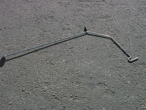
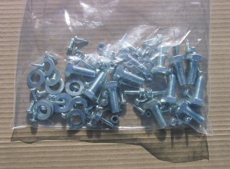
26 CONTENTS OF THE DELIVERY Tube of silicone Sealing ring Cover plate Fans (2-3 pcs) Limit switch (transition limit) Limit switch fastener Limit switch striking plate Condensator box (1-phase) A bag of screws Cleaning tool 26 Ceramic wool
27 NOTES 27
28 WARRANTY Warranty Ariterm Oy grants the equipment it delivers a one-year warranty. The warranty is valid for one year from the commissioning date or at maximum 18 months from the delivery date. The warranty for the pressure vessels manufactured by Ariterm is 5 years from the date of delivery. Ariterm will deliver new parts to replace the faulty ones and the warranty applies to possible manufacturing and material defects. The warranty does not cover consumables or travel costs. The warranty does not cover faults caused by incorrect designing, installation, maintenance or operation, or faults caused by off-specification fuel. Spare part warranty is 12 months. Ariterm will deliver new parts to replace the damaged ones. Unless there are mandatory laws, no other warranty is included in the contract. This paragraph determines exhaustively the Seller s liability for defects and buyer s legal remedies in defect situations. UK Smoke Control Instructions These instructions are intended for use when using any of the below appliances in a Smoke Control Area, when fitted with the correct burner. Arimax 300: Fitted with Biojet Burner 300 Arimax 400: Fitted with Biojet Burner 400 Arimax 500: Fitted with Biojet Burner 500 Fuel, the fuel type that the appliances have been tested on and exempted are wood pellets meeting the below criteria: Diameter 6 8 mm length 5 40 mm Moisture < 10 % Ash content < 0,5 % Net caloric value 4,6 4,9 kwh/kg 28
29 NOTES 29
30 NOTES
31 NOTES 31
32 ORGANISATION CERTIFIED BY PED 2014/68/EU - All Rights to modifications and corrections reserved. ARITERM OY PL 59 (Uuraistentie 1), Saarijärvi Tel , fax
INSTALLATION, OPERATION AND MAINTENANCE. Multijet hydraulic
 INSTALLATION, OPERATION AND MAINTENANCE Multijet 500-1500 hydraulic TABLE OF CONTENTS: FOR THE NEW OWNER 3 INFORMATION ABOUT THE BURNER 4 GENERAL 5 TRANSPORT, HANDLING AND STORAGE 6 MECHANICAL INSTALLATION
TABLE OF CONTENTS ARITERM OY bio burners burn back protection arimax bio kw boilers
 BIO HEATING GUIDE TABLE OF CONTENTS ARITERM OY... 1 Domestic natural renewable energy... 2 Designing and sizing the bio heating system... 2-5 a well designed bio heating system...6-7 bio burners... 8-12
INSTALLATION, OPERATION AND MAINTENANCE. Ariterm Hybrid 20
 INSTALLATION, OPERATION AND MAINTENANCE Ariterm Hybrid 20 TABLE OF CONTENTS General...3 Installation... 4-5 Dimensions - with flue gas exhauster...6 Dimensions - without flue gas exhauster...7 Pipe installations...8
ARITERM OY. Arimatic 500. User manual
 ARITERM OY Arimatic 500 User manual Table of contents 1. General information... 3 2. Transport, storage and package opening... 3 3. Warranty... 3 4. Installation and commissioning... 4 5. System description...
Main components. Buying all components from same manufacturer or reseller it guarantees better compatible and service if something happens
 Main components The bigger the need of heat output is. the bigger the components (storage. boiler. chimney etc.) In private houses the output need of the boiler is about 25 40 kw and in farms from 60 kw-
INSTALLATION AND OPERATING INSTRUCTIONS. Ariterm 60+
 INSTALLATION AND OPERATING INSTRUCTIONS Ariterm 60+ CONTENTS General.... 2 Installation.... 4-5 Installation of temperature limit valve... 6 Measurements and connections... 7 Technical specifications and
INSTALLATION, OPERATION AND MAINTENANCE. Ariterm Vedo
 INSTALLATION, OPERATION AND MAINTENANCE Ariterm Vedo CONTENTS General...3 Installation...4-5 Laddomat 21 Connection diagram...6 Temperature control valve...7 About burning wood...8 Operation...9-11 Service
VETO CLEANER 500 FLUE GAS CLEANER
 As of serial number 3100 0001 VETO CLEANER 500 FLUE GAS CLEANER USER MANUAL SPARE PARTS LIST Manufacturer: ALA TALKKARI Veljekset Ala-Talkkari Oy FI-62130 HELLANMAA TEL. +358 6 433 6333 FAX +358 6 437
Heating, Air Conditioning, Ventilation. Отопление-Кондиционеры-Вентиляция. MTM 8-30 kw UNIVERSAL OIL HEATER OPERATING MANUAL
 Heating, Air Conditioning, Ventilation Отопление-Кондиционеры-Вентиляция MTM 8-30 kw UNIVERSAL OIL HEATER OPERATING MANUAL 1. Usage MTM 8-30 universal oil heater is designed for heating commercial rooms
MCL-BIO. Fuels. Main features. multifuel biomass boiler. group of companies
 multifuel biomass boiler group of companies is an automatic pelletbiomasswood boiler for industrial use (811.16 kw). Thanks to its special design, it can function on multiple fuels without any change on
INSTRUCTION MANUAL FOR OIL BURNER MODELS
 INSTRUCTION MANUAL FOR OIL BURNER MODELS X400 Bio B10 E90-803-001-001-03 Rev 13-1 - Contents Technical specifications Technical data... 3 Working field... 3 Dimensions... 4 Head and electrode settings...
Installation & Maintenance Manual
 Installation & Maintenance Manual MOL 200 S1L (B30A) Oil Burner 11/12 Tel: +44 (0) 1905 794331 Fax: +44 (0) 1905 794017 Email: info@nu-way.co.uk Web: www.nu-way.co.uk DESCRIPTION COMPONENTS 1. Shrouded
TECHNICAL INSTRUCTIONS USE AND MAINTENANCE
 TECHNICAL INSTRUCTIONS USE AND MAINTENANCE Cm Pelet-set For boilers CentroPlus 25/35 and CentroPlus-B 25/35 (solid fuel and wood pellets fuel firing) TUPSCP-K-11-2016-ENG CONTENTS 1.Introduction 2. Status
INSTRUCTIONS FOR INSTALLATION, SETTING AND USE
 BUILT-IN FIREPLACE INSTRUCTIONS FOR INSTALLATION, SETTING AND USE 1. BUILT-IN FIREPLACE SPECIFICATION - WIDE 730 mm - DEPTH 426 mm - HEIGHT 543 mm - NOMINAL POWER 11 KW - CHIMNEY POT DIAMETER Ø 180 mm
INSTRUCTION MANUAL FOR OIL BURNER MODELS
 INSTRUCTION MANUAL FOR OIL BURNER MODELS X500 Bio B10 E90-803-001-001-00 Rev 7-1 - Contents Technical specifications Technical data... 3 Working field... 3 Dimensions... 4 Head and electrode settings...
Installation, operation and care. Pellmax UB. Burner not included Replaces:
 Installation, operation and care Burner not included 2011-11-11 ver: Replaces: Contents 11.11 otes...3 General...4 Function...4 Technical data...5 System principle Pellmax with radiator and tank-in-tank
INSTALLATION AND OPERATING INSTRUCTIONS
 INSTALLATION AND OPERATING INSTRUCTIONS CONTENTS 2 6 7 8 9 10-12 16 17 18 18 19 2 GENERAL TRANSPORTATION, STORAGE AND OPENING THE PACKAGE Receiving the goods - Storage Opening the package 3 INSTALLATION
JUMBO INDIRECT FIRED DIESEL HEATER OPERATING INSTRUCTIONS
 JUMBO INDIRECT FIRED DIESEL HEATER OPERATING INSTRUCTIONS Before using the heater, read and understand all instructions and follow them carefully. The manufacturer is not responsible for damages to goods
VBR EN1.0. Veto Burner Head. 160, 240, 360, 480, 640, 800 and 990 kw. User Manual. Installation and Service. Retailer: Keep this manual.
 VBR20130328EN1.0 Veto Burner Head 160, 240, 360, 480, 640, 800 and 990 kw User Manual Installation and Service Retailer: Keep this manual. 1 Contents 1. Introduction... 4 1.1. Contact information... 4
SWEBO Bioenergy Manual pellet burner PB20 Rev no. Date Page PBM1: (36) Installation and maintenance instructions
 Installation and maintenance instructions") PBM1:12 2018-01-22 1 (36) Installation and maintenance instructions PBM1:12 2018-01-22 2 (36) TABLE OF CONTENTS 1 GENERAL INFORMATION... 5 1.1 PELLET STORAGE... 5 1.2 CONSTRUCTION AND FUNCTION... 6 1.2.1
PBM1:12 2018-01-22 1 (36) Installation and maintenance instructions PBM1:12 2018-01-22 2 (36) TABLE OF CONTENTS 1 GENERAL INFORMATION... 5 1.1 PELLET STORAGE... 5 1.2 CONSTRUCTION AND FUNCTION... 6 1.2.1
INLINE СENTRIFUGAL FAN BOX BOX-R OPERATION MANUAL
 INLINE СENTRIFUGAL FAN BOX BOX-R OPERATION MANUAL CONTENT 3 Introduction 3 General 3 Safety rules 3 Storage and transportation rules 3 Manufacturer s warranty 4 Fan design 4 Delivery set 5 Technical data
INSTRUCTION MANUAL FOR OIL BURNER MODELS
 INSTRUCTION MANUAL FOR OIL BURNER MODELS X500-2 Low voltage 12v dc Brushed motor E90-803-001-005-01 Rev 4-1 - Contents Technical specifications Technical data...3 Working field...3 Dimensions...4 Head
TECHNICAL AND OPERATIONAL DOCUMENTATION
 METAL AND BOILER FACTORY 28-100 Busko-Zdrój, Owczary, ul Przemysłowa 3 Tel No +4841 378 46 19, fax +4841 370 83 10 TECHNICAL AND OPERATIONAL DOCUMENTATION SAS MULTI FLAME BURNER ADAPTED FOR BURNING OF
40E ELECTRIC FAN HEATER
 40E ELECTRIC FAN HEATER PRODUCT MANUAL IMPORTANT READ AND UNDERSTAND THIS MANUAL BEFORE ASSEM- BLING, STARTING OR SERVICING THE HEATER. IMPROPER USE OF HEATER CAN CAUSE SERIOUS INJURY. KEEP THIS MANUAL
SERVICE AND INSTALLATION MANUAL MODELS HDO(H) OIL FOR YOUR SAFETY
 OIL FOR YOUR SAFETY") Bousquet Technologies Inc. 2121, Nobel, Ste Julie, Quebec, Canada, J3E1Z9 SERVICE AND INSTALLATION MANUAL MODELS HDO(H) OIL Oil-Fired air heater for industrial and commercial use. FOR YOUR SAFETY Do not
Bousquet Technologies Inc. 2121, Nobel, Ste Julie, Quebec, Canada, J3E1Z9 SERVICE AND INSTALLATION MANUAL MODELS HDO(H) OIL Oil-Fired air heater for industrial and commercial use. FOR YOUR SAFETY Do not
SWEBO Bioenergy Manual pellet burner PB50 Rev no. Date Page PBM1: (37) Installation and maintenance instructions
 Installation and maintenance instructions") PBM1:12 2008-10-16 1 (37) Installation and maintenance instructions PBM1:12 2008-10-16 2 (37) TABLE OF CONTENTS 1 GENERAL INFORMATION... 5 1.1 PELLET STORAGE... 6 1.2 CONSTRUCTION AND FUNCTION... 7 1.2.1
PBM1:12 2008-10-16 1 (37) Installation and maintenance instructions PBM1:12 2008-10-16 2 (37) TABLE OF CONTENTS 1 GENERAL INFORMATION... 5 1.1 PELLET STORAGE... 6 1.2 CONSTRUCTION AND FUNCTION... 7 1.2.1
100 step modulated Wood Pellet Boiler
 100 step modulated Wood Pellet Boiler EN 303-5 approved by DTI (Danish Technological Institute) Approved for pressure expansion Energy class AA Approved www.kedco.ie Kedco Boiler Manual Version 1.3 Page
PELLET BURNER PV 350
 PELLET BURNER PV 350 INSTRUCTION MANUAL v1.1 1 PRODUCT DESCRIPTION...3 2 SAFETY RULES...3 3 WARNINGS...4 4 INSTALLATION INSTRUCTIONS...5 4.1 BOILER REQUIREMENTS...5 4.2 PELLET CONTAINER...6 4.3 INSTALLATION
SOUND-INSULATED FAN. Iso-K OPERATION MANUAL. Iso-K_v.1(2)-EN.indd :20:59
-EN.indd :20:59") SOUND-INSULATED FAN OPERATION MANUAL _v.1(2)-en.indd 1 10.08.2015 15:20:59 CONTENT Introduction 3 General 3 Safety rules 3 Transport and storage requirements 3 Manufacturer's warranty 3 Fan design 4 Delivery
SOUND-INSULATED FAN OPERATION MANUAL _v.1(2)-en.indd 1 10.08.2015 15:20:59 CONTENT Introduction 3 General 3 Safety rules 3 Transport and storage requirements 3 Manufacturer's warranty 3 Fan design 4 Delivery
Light oil / kerosene burner
 Installation, use and maintenance instructions Light oil / kerosene burner One stage operation CODE MODEL TYPE 374445 G5 444T50 290238 (5) - 05/20 TECHNICAL DATA Thermal power output 28 60 kw 2.3 5 kg/h
Light oil - kerosene burner
 Installation, use and maintenance instructions Light oil - kerosene burner One stage operation CODE MODEL TYPE 374374 G3B 437T 90 (4) - 05/0 TECHNICAL FEATURES TYPE 437T Thermal power output 9 35 kw.6
Internet Version for Reference Only INDUCED DRAFT COMMERCIAL WATER HEATERS SUPPLEMENT INSTRUCTIONS TO PART #
 INDUCED DRAFT COMMERCIAL WATER HEATERS SUPPLEMENT INSTRUCTIONS TO PART #238-39387-00 THIS INSTRUCTION SUPPLEMENT IS ONLY INTENDED TO GIVE INSTALLATION INSTRUCTIONS AND INFORMATION RELATED TO THE INDUCED
Corn Flame Energy Corn Stove Model 3000
 Corn Flame Energy Corn Stove Model 3000 Installation and Operation Guide Read thoroughly before starting installation Save this manual for future reference SAFETY NOTICE If this stove is not properly installed,
USE AND MAINTENANCE. Cm Pelet-set (60-90 kw) TECHNICAL INSTRUCTIONS
 TECHNICAL INSTRUCTIONS") CENTROMETAL d.o.o. Glavna 12 40306 Macinec Croatia tel: +385 40 372 600; fax : +385 40 372 611 TECHNICAL INSTRUCTIONS USE AND MAINTENANCE Cm Pelet-set (60-90 kw) For boilers: EKO-CK P 70-110 TUPS-90K-09-2015-E-N-eng
CENTROMETAL d.o.o. Glavna 12 40306 Macinec Croatia tel: +385 40 372 600; fax : +385 40 372 611 TECHNICAL INSTRUCTIONS USE AND MAINTENANCE Cm Pelet-set (60-90 kw) For boilers: EKO-CK P 70-110 TUPS-90K-09-2015-E-N-eng
PELLETS BURNER 15-60kW MOC
 PELLETS BURNER 15-60kW MOC. Please read those documentation before first start up the unit. Improper burner start may lead to its damage and may create a danger for end user! Table of Contents: 1. Admission
Installation, operation and care Firewood boiler Vedolux 40 UB
 Installation, operation and care Firewood boiler Vedolux 40 UB 2008-09-23 Ver 2 Replaces: 05-11 VEDOLUX 40 UB Notes 0809 To be completed when the Vedolux 40 UB is installed Serial number:... Installation
USE AND MAINTENANCE. Cm Pelet-set TECHNICAL INSTRUCTIONS. (14-35 kw) For boilers: EKO-CK P (EKO-CK 20-40) EKO-CKB P (EKO-CKB 20-40)
 For boilers: EKO-CK P (EKO-CK 20-40) EKO-CKB P (EKO-CKB 20-40)") TECHNICAL INSTRUCTIONS USE AND MAINTENANCE Cm Pelet-set (14-35 kw) For boilers: EKO-CK P 20-40 (EKO-CK 20-40) EKO-CKB P 20-40 (EKO-CKB 20-40) TUPS-K-02-2011-E-N-ENG CONTENTS 1. Introduction....... 2. Status
TECHNICAL INSTRUCTIONS USE AND MAINTENANCE Cm Pelet-set (14-35 kw) For boilers: EKO-CK P 20-40 (EKO-CK 20-40) EKO-CKB P 20-40 (EKO-CKB 20-40) TUPS-K-02-2011-E-N-ENG CONTENTS 1. Introduction....... 2. Status
KITCHEN EXHAUST FAN GLEC-6 INSTALLATION AND MAINTENANCE
 KITCHEN EXHAUST FAN GLEC-6 INSTALLATION AND MAINTENANCE 2 GLEC-6 - Installation and maintenance CONTENTS 1 Important information... 3 2 Safety notes... 3 3 Technical description...4 4 Transport... 6 5
BESF Box Ventilator. Installation & Operating Manual USA CAN READ AND SAVE THESE INSTRUCTIONS
 Installation & Operating Manual 3001806 03.02 USA CAN BESF Box Ventilator READ AND SAVE THESE INSTRUCTIONS 1200 Northmeadow Parkway, STE 180 Roswell, GA 30076 (770) 587-3238 (800) 255-2923 Fax (770) 587-4731
INSTRUCTIONS MANUAL FOR USE AND MAINTENANCE
 INSTRUCTIONS MANUAL FOR USE AND MAINTENANCE Carbel models: C-60 Plus C-70 Plus C-80 Plus C-100 Plus C-70 Plus Double-sided C-80 Plus Double-sided C-100 Plus Double-sided CARBEL C/ Ciudad de Cartagena,
Oil Furnace USER S INFORMATION MANUAL FOR THE OPERATION AND MAINTENANCE OF YOUR NEW OIL-FIRED FURNACE
 Oil Furnace USER S INFORMATION MANUAL FOR THE OPERATION AND MAINTENANCE OF YOUR NEW OIL-FIRED FURNACE MODEL PO8LAA LOW-BOY NOTE TO INSTALLER: THIS MANUAL MUST BE LEFT WITH THE EQUIPMENT USER. MODEL PO8UAA
Indirect gas-fired air heater
 Indirect gas-fired air heater SERIES HD INSTALLATION AND SERVICE MANUAL MANUFACTURED BY : BROTHERS LIMITED WARNING Improper installation, modification, adjustment or maintenance may cause damage, injury
eurofire BIG 100, 200, 300 kw
 Datum 080603, rev 0 eurofire BIG 100, 200, 300 kw The Pellet Burner of the 21 st Century Ekosystem AB Björkevägen 84, S-805 97 GÄVLE, Sweden Table of Contents General Information 3 Read these instructions
INSTRUCTIONS FOR INSTALLATION AND MANUAL Solid fuel stove for central heating THERMO IN
 INSTRUCTIONS FOR INSTALLATION AND MANUAL Solid fuel stove for central heating THERMO IN To respected customer, We are very pleased for your trust and your decision to buy our product. You made a good choice,
Solid fuel hot water boiler TKH KW INSTRUCTIONS MANUAL for usage and maintenance
 Solid fuel hot water boiler TKH 250-400 KW INSTRUCTIONS MANUAL for usage and maintenance Prhovacka bb 22310 Simanovci, Srbija Tel/Fax. +381 22 480404 +381 63 259422 oce@termomont.rs www.termomont.rs April
100 FLUEBOOST
 100 FLUEBOOST f l u e b o o s t 1 0 0 The flueboost is a box shaped centrifugal fan unit with in line spigots for the flue connection, a pressure switch to ensure safe operation, all within a compact package.
INSTALLATION, OPERATION AND MAINTENANCE. ARITERM SWEDEN AB Installation, Operation & Maintenance /28
 INSTALLATION, OPERATION AND MAINTENANCE ARITERM SWEDEN AB Installation, Operation & Maintenance - 2009.02.18-1/28 CONTENTS IMPORTANT INFORMATION 4 4 5 Notification to building authority Inspection Sweeping
INSTRUCTIONS FOR USE OF COMBINED BOILER INTENDED FOR COMBUSTION OF BOTH PELLETS AND SOLID FUEL ABC COMBO
 INSTRUCTIONS FOR USE OF COMBINED BOILER INTENDED FOR COMBUSTION OF BOTH PELLETS AND SOLID FUEL ABC COMBO .Technical specifications Boiler power DESCRIPTION Water content in a boiler Required draft Supply
MANUAL FOR USE AND INSTALATION STOVE MODELS: D11-D17
 MANUAL FOR USE AND INSTALATION STOVE MODELS: D11-D17 CE Tested by the DIN EN 13240 15a B-VG Austria Type 1 Color Emajl d.o.o. Alaginci 87 a 34000 Požega Croatia www.color.hr team@color.hr 1 Attention!
Combined boiler. for solid fuel and pellets
 Combined boiler ATTACK WOOD&PELLET for solid fuel and pellets W W W. A T T A C K. S K MODEL STRUC TURE OF THE AT TACK BOILERS THE NEW LINE OF ATTACK BOILERS FOR WOOD AND PELLETS 3000 000 6000 4 ATTACK
USER S INFORMATION MANUAL
 USER S INFORMATION MANUAL UPFLOW & DOWNFLOW/HORIZONTAL CONDENSING GAS FURNACES SAFETY Recognize this symbol as an indication of Important Safety Information If not installed, operated and maintained in
GLEB Kitchen exhaust fan
 GLEB Kitchen exhaust fan Installation and Maintenance??.1.2013 Contents 1. Important information 2. Safety notes 3. Technical description 4. Transport 5. Mounting instructions 6. Commissioning 7. Maintenance
15 20 kw kw kw
 Burner Set-up Details 15 20 kw 20 26 kw 29 36 kw Riello RDB2 Please read these instructions carefully before commissioning and using this appliance. To be retained by the householder HEALTH AND SAFETY
40E ELECTRIC FAN HEATER
 40E ELECTRIC FAN HEATER PRODUCT MANUAL IMPORTANT READ AND UNDERSTAND THIS MANUAL BEFORE ASSEM- BLING, STARTING OR SERVICING THE HEATER. IMPROPER USE OF HEATER CAN CAUSE SERIOUS INJURY. KEEP THIS MANUAL
ST 40 Oil Burner. Installation & Maintenance Manual
 ST 40 Oil Burner Installation & Maintenance Manual 178 093 13 Thank you for choosing a Nu-way burner. As you would expect from a Company who has a pedigree of more than 75 years in the heating industry,
Kyung Dong Oil Boiler. Contents. 1. General Warnings Safety Warnings
 Contents 1. General Warnings --------------------- 1 2. Safety Warnings ----------------------- 2 3. Parts and structure --------------------- 7 4. Safety Device ------------------------- 9 5. Checkups
Operating manual. Pellet boiler. Orlan Pellet ISO 9001
 Operating manual Pellet boiler Orlan Pellet ISO 9001 Contens 1. Boiler s use...................................................................... 3 2. Boiler s way of working...........................................................
Operating Manual PELLEMATIC PES CMP06 TO_VA6.39 Pelletronic TOUCH ENGLISH. PE 1491 EN_TO 1.0 Europe s specialist in pellet heating
 Operating Manual PELLEMATIC PES 12 56 CMP06 TO_VA6.39 Pelletronic TOUCH ENGLISH PE 1491 EN_TO 1.0 Europe s specialist in pellet heating Title: Operating manual PES 12-56 Article number: PE 1491 EN_TO 1.0
Providing sustainable energy solutions worldwide. Installation- and maintenance instruction MOL1650 T3N 323 2FH.
 178 024 63-2 2016-11-22 Providing sustainable energy solutions worldwide Installation- and maintenance instruction MOL1650 T3N 323 2FH No control DISCRIPTION Components 2 3 4 5 6 7 8 9 18, 19 13 10 17
Silencer Preheater unit Electric post-heating unit Water circulated post-heating unit CO 2 sensor %RH sensor Pressure difference switch LON converter
 VALLOX Product Code: 3158400 L 3158410 R SILENCER (OPTIONAL) INSTRUCTIONS FOR USE AND MAINTENANCE WATER CIRCULATED POST-HEATING UNIT (OPTIONAL) ELECTRIC POST-HEATING UNIT (OPTIONAL)) PREHEATER (OPTIONAL)
1. The structure and its description
 Thank you for using our KYUNG-DONG NAVIEN. To use this boiler in the proper way, be sure to read this manual fully before using it, and keep this manual with the warranty of the quality in a safe place.
BIOMASS BOILER ATTACK PELLET 30 AUTOMATIC PLUS
 BIOMASS BOILER ATTACK PELLET 30 AUTOMATIC PLUS W W W. A T T A C K. S K MODEL STRUC TURE OF THE AT TACK BOILERS THE NEW LINE OF ATTACK BOILERS FOR WOOD AND PELLETS 3000 000 6000 4 ATTACK FD PELLET yattack
READ AND SAVE THESE INSTRUCTIONS
 READ AND SAVE THESE INSTRUCTIONS WARNING TO REDUCE THE RISK OF FIRE, ELECTRIC SHOCK, OR INJURY TO PERSONS, OBSERVE THE FOLLOWING: 1. Use this unit only in the manner intended by the manufacturer. If you
POWER VENTER SYSTEM. Model: PVO-300, PVO-600
 POWER VENTER SYSTEM Model: PVO-300, PVO-600 Included is one ETL and cetl listed Power Venter to be used primarily with a single 120VAC controlled oil fired furnace, boiler, or water heater. The PVO may
Installation, operation and care. Pellet burner Replaces:
 Installation, operation and care Pellet burner 2008-09-01 ver: Replaces: konv006 Contents 0809 General...3 Notes...4. Combustion values Function...5. Technical data Installation...6. Boiler Chimney Boiler
A-150 Installation Instructions
 1. IMPORTANT: Place furnace floor on a flat level surface. The end of the floor without the angle is the stoker-hopper end. Position the floor with the short angle welded to it towards the chimney this
Importance of a Draught Regulator
 Importance of a Draught Regulator The purpose of a chimney (stack) is to generate a draught (draft) that will transport smoke and fumes away from the point of combustion. The chimney design and arrangement
Gasification boiler PYROLYT INSTRUCTION MANUAL. ver. 1.1
 Gasification boiler PYROLYT INSTRUCTION MANUAL ver. 1.1 THERMOSTAHL would like to thank and congratulate you on your purchasing this boiler device and ensure that you have made a good choice. PYROLYT boiler
User Manual Installation, Operation and Service
 V8B20130328EN1.0 Veto 8 User Manual Installation, Operation and Service Retailer: Keep this manual. 1 Contents 1. Introduction... 6 1.1. Contact information... 6 1.2. Type plate and delivery information...
SAUNA HEATER INSTALLATION AND OPERATING MANUAL
 SAUNA HEATER INSTALLATION AND OPERATING MANUAL Type Stoveman 13 Models 13R; 13R-M; 13; 13-M; 13R-LS; 13R-M-LS; 13-M-LS; 13-LS Heating output in the sauna room 15.4 kw Sauna room cubage 6-13 m³ Fuel Wood
USER S INFORMATION MANUAL
 USER S INFORMATION MANUAL UPFLOW/HORIZONTAL & DOWNFLOW TWO STAGE INDUCED DRAFT GAS FURNACES Recognize this symbol as an indication of Important Safety Information If the information in this manual is not
Easyfire Standalone biomass pellet boiler
 Easyfire Standalone biomass pellet boiler DESIGN Essential and pleasant AESTETIC, small size If the humanity is in balance with the resources of nature, the respect for the environment will be possible.
OPERATING & MAINTENANCE MANUAL
 DO NOT DISCARD OPERATING & MAINTENANCE MANUAL Quality Fireplaces for Life INSTALLER: LEAVE THIS MANUAL WITH THE APPLIANCE Contact local building or fire officials about restrictions and installation inspection
Providing sustainable energy solutions worldwide. Installation- and maintenance instruction B 30 A
 178 038 51-2 2016-07-08 Providing sustainable energy solutions worldwide Installation- and maintenance instruction B 30 A DESCRIPTION Components 1. Shrouded disc 2. Nozzle 3. Ignition electrodes 4. Nozzle
SPECIFICATIONS PART NAME
 SPECIFICATIONS MODEL High HEAT RATING Low FUEL TANK CAPACITY BURNING TIME DIMENSIONS(W x D x H) WEIGHT VOLTAGE / FREQUENCY ELECTRICAL CONSUMPTION LC-S27 9,900 BTU / 2.9 kw 2,900 BTU / 0.8 kw 4.0 lit. 14.2~
model No: ir20.v2 FUSE
 InstructioNS for: model No: ir20.v2 INFRARED PARAFfIN / KEROSENE / diesel HEATER 70000Btu 230V Thank you for purchasing a Sealey product. Manufactured to a high standard this product will, if used according
en Direct oil-fired space heaters HD... Operator's manual
 0211670en 002 12.2007 Direct oil-fired space heaters HD... Operator's manual Table of contents 1. Foreword 5 2. Safety information 6 2.1 General recommendations... 6 2.2 Safety devices... 7 2.3 Labels...
HORIZONTAL MULTISTAGE CENTRIFUGAL PUMP
 HORIZONTAL MULTISTAGE CENTRIFUGAL PUMP WWPPCHLFT260 Instructions WWPPCHLFT260_Horizontal Multistage Centrifugal Pump_IB.indd 1 READ THIS MANUAL CAREFULL BEFORE INSTALL, START THE PUMP 1. Suction 2. Plug
Boiler Technical Specifications (2013)
") ACT Bioenergy Boiler Dimensions 0.5-0.85 Million Btu/h (150-250kW) Model CP500 CP600 CP750 CP850 Heat Output in MBtu/h (kw) 510 (150) 610 (180) 750 (220) 850 (250) Height ft (mm) 6 1 (1855) 6 1 (1855)
ACT Bioenergy Boiler Dimensions 0.5-0.85 Million Btu/h (150-250kW) Model CP500 CP600 CP750 CP850 Heat Output in MBtu/h (kw) 510 (150) 610 (180) 750 (220) 850 (250) Height ft (mm) 6 1 (1855) 6 1 (1855)
Ontario Fire Code SECTION 5.10 COMBUSTIBLE DUST PRODUCING PROCESSES. Illustrated Commentary. Office of the Ontario Fire Marshal
 Ontario Fire Code SECTION 5.10 COMBUSTIBLE DUST PRODUCING PROCESSES Illustrated Commentary Office of the Ontario Fire Marshal Combustible Dust Illustrated Commentary 1 Mechanical Exhaust Systems 5.10.1.1.
Wood Pellets Burner Bio comfort
 Wood Pellets Burner Bio comfort 100 step modulated Woody Generation EN 303-5 approved by DTI (Danish Technological Institute) Approved for pressure expansion Energy class AA NBE pellet system INSTALLATION
HOTPLATE COUNTERTOP AND OVEN RANGE
 F900 SERIES User, installation and servicing instructions HOTPLATE COUNTERTOP AND OVEN RANGE E9042, E9084, E9184 Read these instructions before use DATE PURCHASED: MODEL NUMBER: SERIAL NUMBER: DEALER:
CAR-MON DUST COLLECTORS SERIES 207, 2410, 3015
 INSTALLATION-OPERATION-MAINTENANCE CAR-MON DUST COLLECTORS SERIES 207, 2410, 3015 TEFC 3 phase motor Outlet duct Fan wheel housing Inlet duct connection After filter transition Optional after filter unit
Eclipse Self-Check UV Scanner
 856 Instruction Manual 10/18/2010 Eclipse Self-Check UV Model 5602-91 Version 1 Introduction The self-check UV is used for continuous gas or oil flames. A mechanical shutter in the scanner closes briefly
Light oil burners. One stage operation
 Installation, use and maintenance instructions Light oil burners One stage operation CODE MODEL TYPE 3505 RDB CF 38 50 T3 350050 RDBR CF 6 50 TR 35050 RDBR CF 33 50 TR 35050 RDBR CF 38 50 T3R 350650 RDBR
Maintenance 50 Serie CAUTION. Before resetting your electronic card that displays an error code. OVERHEAT MESSAGE
 29-10-2013 CAUTION Before resetting your electronic card that displays an error code. OVERHEAT MESSAGE Service the stove COMPLETELY as described in this manual. Check the chimney pipe. BLOCKED FLUE MESSAGE
Operating Instructions Manual Janfire NH/Integral Pellets Burner with External Auger
 Operating Instructions Manual Janfire NH/Integral Pellets Burner with External Auger 11899008 R1 EN Janfire 2008 Due to constant development, Janfire AB reserves the right to change part or parts of this
USER S MANUAL, MAINTENANCE MANUAL INSTALLATION INSTRUCTIONS
 D F:\Home\RD\ME\FUNNY\FUNNYGB.WP IN-FIRE Jubilee USER S MANUAL, MAINTENANCE MANUAL INSTALLATION INSTRUCTIONS 07DHIFFUA 03/99-1 - Dear Customer! Congratulations on the purchase of your new Bodart & Gonay
User Manual Installation, Operation and Service
 VCM20130328EN1.0 Veto ChipMatic User Manual Installation, Operation and Service Retailer: Keep this manual. 1 Contents 1. Introduction... 6 1.1. Contact information... 6 1.2. Type plate and delivery information...
Gas Fire Patio Heater Q9
 Gas Fire Patio Heater Q9 Instruction Manual Please read the manual BEFORE you unpack or install the fire TABLE OF CONTENTS Warning 3 Getting Started 4 What s Included 5 Assembly Procedures 6 Product Drawing
DH-Direct Fired Poultry Farm Diesel Heater
 DH-Direct Fired Poultry Farm Diesel Heater Comparison of Diesel Heater to Gas Heater Diesel LPG Gas LPG Gas KW 43 70 120 Fuel consumption/hr 3 5.1 8.8 Heat output 37000 60000 100000 Cost of fuel/lit or
Hickory Rotisseries. Machine Type N / 5. 5 E 200ºF - 550ºF. Final Inspection:
 Installation Manual USA Hickory Rotisseries Models: N/5.5 E Machine Type N / 5. 5 E Total Power Rating Elements / Spits Electrical Rating Temperature Range Timer Delivery Date: 6000 or 8400 Watts 4 Elements
Gas Fire Patio Heater Lhotse-817
 Gas Fire Patio Heater Lhotse-817 Instruction Manual Please read the manual BEFORE you unpack or install the fire TABLE OF CONTENTS Warning 3 Getting Started 4 What s Included 5 Assembly Procedures 6 Product
Propane Flame Projector Safety instructions and operating manual
 Bigflame Propane Flame Projector Safety instructions and operating manual 1 Flame projector Bigflame Safety instructions Caution The directions in this manual must be followed strictly. It is imperative
Page 1. Cube Ref:
 Page 1 Cube Ref: 388117 Linedrawing: Technical characteristics: Unit dimensions (cm) Fire box dimensions (cm) Flue Diameter Flue outlet Recommended fuel Log size loading from the front: Panoramic glass
INSTALLATION, COMMISSIONING AND OPERATING MANUAL
 INSTALLATION, COMMISSIONING AND OPERATING MANUAL 1 YTBV-D-CE42_0109 CONTENT Available models and capacities Supplier information Warranty Safety Emergency stops/ shutdowns About this manual Models Physical
Providing sustainable energy solutions worldwide. Installation- and maintenance instruction B 10 E R
 178 013 03-2 2016-05-26 Providing sustainable energy solutions worldwide Installation- and maintenance instruction B 10 E R DESCRIPTION Components 1. Scale, nozzle assembly 2. Nozzle assembly adjustment
TECHNICAL MANUAL BIOTEC 25 AND BIOTEC 40
 TECHNICAL MANUAL BIOTEC 25 AND BIOTEC 40 2 INDEX INDEX Safety information.......4 Technical data...5 Boiler features...6 Technical information........7 Fuel...... 8 Construction and function...... 9 Hydraulic
Multi Energy Boilers. Duo 1 & 2 Triplex 1000 & 3000 Biotriplex. Oil Gas LPG Wood Briquettes Electricity Solar thermal Solar photovoltaics
 Multi Energy Boilers Duo 1 & 2 Triplex 0 & 3000 Biotriplex Oil Gas LPG Wood Briquettes Electricity Solar thermal Solar photovoltaics Jaspi Multi Energy Jaspi has been developing and manufacturing highlong
18E ELECTRIC FAN HEATER
 18E ELECTRIC FAN HEATER MODEL 18E-1 (Single Phase) MODEL 18E-3 (Three Phase) PRODUCT MANUAL IMPORTANT READ AND UNDERSTAND THIS MANUAL BEFORE ASSEM- BLING, STARTING OR SERVICING THE HEATER. IMPROPER USE