CAUTION ! WARNING SAFETY CONSIDERATIONS INTRODUCTION. 38MGR Multi-zone Outdoor Unit Ductless System Sizes 18, 24, 30, 36 and 48
|
|
|
- Clare Bruce
- 5 years ago
- Views:
Transcription

1 38MGR Multi-zone Outdoor Unit Ductless System Sizes 18, 24, 30, 36 and 48 TABLE OF CONTENTS PAGE SAFETY CONSIDERATIONS... 1 INTRODUCTION... 1 MODEL/SERIAL NUMBER NOMENCLATURES... 2 SPECIFICATIONS OUTDOOR... 3 COMPATIBILITY TABLE... 4 DIMENSIONS OUTDOOR... 5 CLEARANCES OUTDOOR... 9 ELECTRICAL DATA... 9 WIRING CONNECTION DIAGRAMS WIRING DIAGRAMS REFRIGERATION CYCLE DIAGRAMS REFRIGERANT LINES SYSTEM EVACUATION AND CHARGING ELECTRONIC FUNCTION TROUBLESHOOTING OUTDOOR UNIT DISPLAY DIAGNOSIS AND SOLUTION APPENDIX SAFETY CONSIDERATIONS Installing, starting up, and servicing air conditioning equipment can be hazardous due to system pressures, electrical components, and equipment location (roofs, elevated structures, etc.). Only trained, qualified installers and service mechanics should install, start up, and service this equipment. Untrained personnel can perform basic maintenance functions such as cleaning coils. All other operations should be performed by trained service personnel. When working on the equipment, observe precautions in the literature and on tags, stickers, and labels attached to the equipment. Follow all safety codes. Wear safety glasses and work gloves. Keep quenching cloth and fire extinguisher nearby when brazing. Use care in handling, rigging, and setting bulky equipment. Read this manual thoroughly and follow all warnings or cautions included in literature and attached to the unit. Consult local building codes and National Electrical Code (NEC) for special requirements. Recognize safety information. This is the safety alert symbol!!. When you see this symbol on the unit and in instructions or manuals, be alert to the potential for personal injury. Understand these signal words: DANGER, WARNING, and CAUTION. Service Manual These words are used with the safety alert symbol. DANGER identifies the most serious hazards which will result in severe personal injury or death. WARNING signifies hazards which could result in personal injury or death. CAUTION is used to identify unsafe practices which may result in minor personal injury or product and property damage. NOTE is used to highlight suggestions which will result in enhanced installation, reliability, or operation.! WARNING ELECTRICAL SHOCK HAZARD Failure to follow this warning could result in personal injury or death. Before installing, modifying, or servicing system, main electrical disconnect switch must be in the OFF position. There may be more than 1 disconnect switch. Lock out and tag switch with a suitable warning label.!! WARNING EXPLOSION HAZARD Failure to follow this warning could result in death, serious personal injury, and/or property damage. Never use air or gases containing oxygen for leak testing or operating refrigerant compressors. Pressurized mixtures of air or gases containing oxygen can lead to an explosion. CAUTION EQUIPMENT DAMAGE HAZARD Failure to follow this caution may result in equipment damage or improper operation. Do not bury more than 36 in. (914 mm) of refrigerant pipe in the ground. If any section of pipe is buried, there must be a 6 in. (152 mm) vertical rise to the valve connections on the outdoor units. If more than the recommended length is buried, refrigerant may migrate to the cooler buried section during extended periods of system shutdown. This causes refrigerant slugging and could possibly damage the compressor at start up. INTRODUCTION This Service Manual provides the necessary information to service, repair, and maintain the multi zone family of heat pumps. Section 2 of this manual has an appendix with data required to perform troubleshooting. Use the Table of Contents to locate a desired topic.

2 MODEL/SERIAL NUMBER NOMENCLATURES Table 1 Unit Sizes SYSTEM TONS kbtuh VOLTAGE - PHASE OUTDOOR MODEL / MGRQ18B / MGRQ24C / MGRQ30D / MGRQ36D / MGRQ48E--3 INDOOR UNIT 38 MG R Q 18 B = OUTDOOR UNIT MG = ALL VOLTAGE 3 = 208/ UNIT TYPE R = OUTDOOR UNIT SYSTEM TYPE Q = HEAT PUMP NOMINAL CAPACITY /2 TONS 24-2 TONS 30-21/2 TONS 36-3 TONS 48-4 TONS NOT USED MAXIMUM NUMBER OF FAN COIL UNITS THAT CAN BE CONNECTED TO THE OUTDOOR UNIT B = 1:2 C = 1:3 D = 1:4 E = 1: V Week of Manufacture Sequential Serial Number Year of Manufacture V = ALL MODELS Use of the AHRI Certified TM Mark indicates a manufacturer s participation in the program For verification of certification for individual products, go to 2
3 SPECIFICATIONS OUTDOOR SYSTEM Performance n-ducted Performance Combination Ducted and n-ducted Performance Ducted Operating Range Piping Refrigerant Electrical Compressor Outdoor Table 2 Outdoor HEAT PUMP Size Outdoor Model 38MGRQ18B--3 38MGRQ24C--3 38MGRQ30D--3 38MGRQ36D--3 38MGRQ48E--3 Max Number of Zones Energy Star YES YES YES YES YES Cooling System Tons Cooling Rated Capacity Btu/h 18,000 24,000 30,000 36,000 48,000 Cooling Cap. Range Min-Max Btu/h 5810~ ~ ~ ~ ~ SEER EER Heating Rated Capacity (47 F) Btu/h 19,000 23,000 28,000 36,000 48,000 Heating Rated Capacity (17 F) Btu/h 12,000 13,600 17,400 23,200 29,600 Heating Max. Capacity (5 F) Btu/h 13,900 23,000 28,000 36,000 36,000 Heating Cap. Range Min-Max Btu/h 5760~ ~ ~ ~ ~ HSPF COP (47 F) W/W COP (17 F) W/W COP (5 F) W/W Energy Star NO YES NO NO NO Cooling System Tons Cooling Rated Capacity Btu/h 18,000 23,000 29,000 35,500 48,000 Cooling Cap. Range Min-Max Btu/h 5795~ ~ ~ ~ ~ SEER EER Heating Rated Capacity (47 F) Btu/h 18,750 22,000 28,000 36,000 49,000 Heating Rated Capacity (17 F) Btu/h 11,700 12,900 17,300 23,800 31,300 Heating Max. Capacity (5 F) Btu/h 14,150 22,000 28,000 35,500 36,400 Heating Cap. Range Min-Max Btu/h 5650~ ~ ~ ~ ~ HSPF COP (47 F) W/W COP (17 F) W/W COP (5 F) W/W Energy Star NO YES NO NO NO Cooling System Tons Cooling Rated Capacity Btu/h 18,000 22,000 28,000 35,000 48,000 Cooling Cap. Range Min-Max Btu/h 5780~ ~ ~ ~ ~ SEER EER Heating Rated Capacity (47 F) Btu/h 18,500 21,000 28,000 36,000 50,000 Heating Rated Capacity (17 F) Btu/h 11,400 12,200 17,200 24,400 33,000 Heating Max. Capacity (5 F) Btu/h 14,400 21,000 28,000 35,000 36,800 Heating Cap. Range Min-Max Btu/h 5539~ ~ ~ ~ ~ HSPF COP (47 F) W/W COP (17 F) W/W COP (5 F) W/W Cooling Outdoor DB Min-Max F( C) -13~ 122 (-25~ 50) -13~ 122 (-25~ 50) -13~ 122(-25~ 50) -13~ 122(-25~ 50) -13~ 122(-25~ 50) Heating Outdoor DB Min-Max F( C) -22~86 (-30~30) -22~86 (-30~30) -22~86 (-30~30) -22~86 (-30~30) -22~86 (-30~30) Total Piping Length ft (m) 131(40) 197(60) 263(80) 328(100) 328(100) Piping to furthest FCU ft (m) 82 (25) 98 (30) 115(35) 115(35) 115 (35) Drop (OD above ID) ft (m) 49(15) 49(15) 49(15) 65(20) 65(20) Lift (OD below ID) ft (m) 49(15) 49(15) 49(15) 65(20) 65(20) Pipe Connection Size-Liquid in (mm) 1/4*2 1/4*3 1/4*4 1/4*4 1/4*5 (6.35*2) (6.35*3) (6.35*4) (6.35*4) (6.35*5) Pipe Connection Size-Suction in (mm) 3/8*2 3/8*3 1/2 *1+ 3/8*3 1/2 *1+ 3/8*3 1/2 *2+ 3/8*3 (9.52*2) (9.52*3) (12.7*1+9.52*3) (12.7*1+9.52*3) (12.7*2+9.52*3) Type R410A R410A R410A R410A R410A Charge lbs (kg) 4.41 (2.0) 6.17(2.8) 6.61 (3.0) (4.6) (4.6) Metering Device EEV EEV EEV EEV EEV Voltage, Phase, Cycle V/Ph/Hz 208/ / / / / Power Supply Indoor unit powered from outdoor unit MCA A MOCP-Fuse Rating A Type Rotary Inverter Rotary Inverter Rotary Inverter Rotary Inverter Rotary Inverter Model ATM150D23UFZ ATF235D22UMT ATF310D43UMT ATQ360D1UMU ATQ360D1UMU Oil Type ESTER OIL VG74 ESTER OIL VG74 ESTER OIL VG74 ESTER OIL VG74 ESTER OIL VG74 Oil Charge Fl. Oz Rated Current RLA Unit Width in (mm) (948) (1047) (1047) (1045) (1045) Unit Height in (mm) (702) (810) (810) (1333) (1333) Unit Depth in (mm) (376) (455) (455) (448) (448) Net Weight lbs (kg) (48) (68) (71) (100.5) (101.5) Airflow CFM 1,390 2,130 2,130 4,500 4,500 Sound Pressure db(a)
4 COMPATIBILITY TABLE High Wall Cassette Ducted Floor Console INDOOR UNIT Table 3 Outdoor OUTDOOR UNIT 38MGRQ18B--3 38MGRQ24C--3 38MGRQ30D--3 38MGRQ36D--3 38MGRQ48E--3 40MAQB09B PEQ009BBMA 40MAQB12B PEQ012BBMA 40MAQB18B PEQ018BBMA 40MAQB24B PEQ024BBMA 40MBQB09C REQ009CBMA 40MBQB12C REQ012CBMA 40MBQB18C REQ018CBMA 40MBQB09D REQ009DBMA 40MBQB12D REQ012DBMA 40MBQB18D REQ018DBMA 40MBQB24D REQ024DBMA 40MBQB09F REQ009FBMA 40MBQB12F REQ012FBMA 4
5 DIMENSIONS OUTDOOR Table 4 Dimensions UNIT SIZE Height in (mm) 27.6 (703) (810) (810) (1333) (1333) Width in (mm) (845) (946) (946) (1045) (1045) Depth in (mm) (335) (386) (386) (380) (380) Weight-Net lbs (kg) (48) (68) (71) (101.5) (101.5) NOTE: Master valves are not available on the size 18 unit. Fig. 1 Outdoor Dimensions Size 18 5
6 DIMENSIONS OUTDOOR (CONTINUED) Master Valve Liquid Line Master Valve Suction Line Fig. 2 Outdoor Dimensions Size 24 Master Valve Liquid Line Master Valve Suction Line Fig. 3 Outdoor Dimensions Size 30 6
7 DIMENSIONS OUTDOOR (CONTINUED) Master Valve Liquid Line Master Valve Suction Line Fig. 4 Outdoor Dimensions Size 36 7
8 DIMENSIONS OUTDOOR (CONTINUED) Master Valve Liquid Line Master Valve Suction Line Fig. 5 Outdoor Dimensions Size 48 8
9 CLEARANCES OUTDOOR A Air-inlet E D B C Air-outlet Fig. 6 Outdoor Unit Clearance Table 5 Outdoor Minimum Value UNIT in. (mm) A 24 (609) B 24 (609) C 24 (609) D 4 (101) E 6 (152) NOTE: Outdoor Unit must be mounted at least 2in (50mm) above the maximum anticipated snow depth. ELECTRICAL DATA Table 6 Multi Zone Outdoor Unit UNIT SIZE SYSTEM VOLTAGE OPERATING VOLTAGE COMPRESSOR OUTDOOR FAN VOLT / PHASE / HZ MAX / MIN* RLA FLA HP W MCA MOCP /1/ / x x *Permissible limits of the voltage range at which the unit will operate satisfactorily. LEGEND FLA - Full Load Amps MCA - Minimum Circuit Amps MOCP - Maximum Over Current Protection RLA - Rated Load Amps 9
10 WIRING All wires must be sized per NEC (National Electrical Code) or CEC (Canadian Electrical Code) and local codes. Use the Electrical Data table MCA (minimum circuit amps) and MOCP (maximum over current protection) to correctly size the wires and the disconnect fuse or breakers respectively. Per the caution note, only stranded copper conductors with a 600 volt rating and double insulated copper wire must be used. The use of BX cable is not recommended. Recommended Connection Method for Power and Communication Wiring Power and Communication Wiring: The main power is supplied to the outdoor unit. The field supplied 14/3 power/communication wiring from the outdoor unit to the indoor unit consists of four (4) wires and provides the power for the indoor unit. Two wires are high voltage AC power, one is communication wiring and the other is a ground wire. Recommended Connection Method for Power and Communication Wiring (To minimize communication wiring interference) Power Wiring: The main power is supplied to the outdoor unit. The field supplied power wiring from the outdoor unit to the indoor unit consists of three (3) wires and provides the power for the indoor unit. Two wires are high voltage AC power and one is a ground wire. To minimize voltage drop, the factory recommended wire size is 14/2 stranded with a ground. Communication Wiring: A separate shielded stranded copper conductor only, with a 600 volt rating and double insulated copper wire, must be used as the communication wire from the outdoor unit to the indoor unit. Please use a separate shielded 16GA stranded control wire.! CAUTION EQUIPMENT DAMAGE HAZARD Failure to follow this caution may result in equipment damage or improper operation. Wires should be sized based on NEC and local codes. Use copper conductors only with a minimum 600 volt rating and double insulated copper wire.! CAUTION EQUIPMENT DAMAGE HAZARD Failure to follow this caution may result in equipment damage or improper operation. Be sure to comply with local codes while running wire from the indoor unit to the outdoor unit. Every wire must be connected firmly. Loose wiring may cause the terminal to overheat or result in unit malfunction. A fire hazard may also exist. Therefore, ensure all wiring is tightly connected. wire should be allowed to touch the refrigerant tubing, compressor or any moving parts. Disconnecting means must be provided and shall be located within sight and readily accessible from the air conditioner. Connecting cable with conduit shall be routed through a hole in the conduit panel. 10
11 CONNECTION DIAGRAMS Indoor Indoor Unit A Unit A Power Supply Signal High Voltage L1 L2 S Ground GND Indoor Indoor Unit B Unit B Power Supply Signal High Voltage L1 L2 S Ground GND FIELD POWER SUPPLY CONNECTING CABLE OUTDOOR TO INDOOR CONNECTING CABLE OUTDOOR TO INDOOR L2 L1(A) L2(A) S(A) L1(B) L2(B)S(B) Main Power to Indoor Power to Indoor Power Supply Indoor Unit A Unit A Unit B Ground Indoor Unit B Signal Signal High High Voltage Voltage Fig. 7 Connection Diagram Size 18K 2 Zone Indoor Indoor Unit A Unit A Power Supply Signal High Voltage L1 L2 S Ground GND Indoor Indoor Unit B Unit B Power Supply Signal High Voltage L1 L2 S Ground GND Indoor Indoor Unit C Unit C Power Supply Signal High Voltage L1 L2 S Ground GND FIELD POWER SUPPLY CONNECTING CABLE OUTDOOR TO INDOOR CONNECTING CABLE OUTDOOR TO INDOOR CONNECTING CABLE OUTDOOR TO INDOOR L2 L1(A) L2(A) S(A) L1(B) L2(B) S(B) L1(C) L2(C) S(C) Main Power to Indoor Power Supply Indoor Unit A Unit A Ground Signal High Voltage Power to Indoor Power to Indoor Indoor Unit B Unit B Indoor Unit C Unit C Signal Signal High High Voltage Voltage Fig. 8 Connection Diagram Size 24K 3 Zone Indoor Indoor Unit A Unit A Power Supply Signal High Voltage L1 L2 S Ground GND Indoor Indoor Unit B Unit B Power Supply Signal High Voltage L1 L2 S Ground GND Indoor Indoor Unit C Unit C Power Supply Signal High Voltage L1 L2 S Ground GND Indoor Indoor Unit D Unit D Power Supply Signal High Voltage L1 L2 S Ground GND FIELD POWER SUPPLY CONNECTING CABLE OUTDOOR TO INDOOR CONNECTING CABLE OUTDOOR TO INDOOR CONNECTING CABLE OUTDOOR TO INDOOR CONNECTING CABLE OUTDOOR TO INDOOR L2 L1(A) L2(A) S(A) L1(B) L2(B) S(B) L1(C) L2(C) S(C) L1(D) L2(D)S(D) Main Power to Indoor Power Supply Indoor Unit A Unit A Ground Signal High Voltage Power to Indoor Power to Indoor Power to Indoor Indoor Unit B Unit B Indoor Unit C Unit C Indoor Unit D Unit D Signal Signal Signal High High High Voltage Voltage Voltage Fig. 9 Connection Diagram Size 30K 4 Zone 11
12 CONNECTION DIAGRAMS (CONTINUED) Indoor Indoor Unit A Unit A Power Supply Signal High Voltage L1 L2 S Ground GND Indoor Indoor Unit B Unit B Power Supply Signal High Voltage L1 L2 S Ground GND Indoor Indoor Unit C Unit C Power Supply Signal High Voltage L1 L2 S Ground GND Indoor Indoor Unit D Unit D Power Supply Signal High Voltage L1 L2 S Ground GND FIELD POWER SUPPLY CONNECTING CABLE OUTDOOR TO INDOOR CONNECTING CABLE OUTDOOR TO INDOOR CONNECTING CABLE OUTDOOR TO INDOOR CONNECTING CABLE OUTDOOR TO INDOOR L2 L1(A) L2(A) S(A) L1(B) L2(B) S(B) L1(C) L2(C) S(C) L1(D) L2(D)S(D) Main Power Supply Ground Power to Indoor Power to Indoor Power to Indoor Power to Indoor Indoor Unit A Unit A Indoor Unit B Unit B Unit C Indoor Unit C Indoor Unit D Unit D Signal Signal Signal Signal High High High High Voltage Voltage Voltage Voltage Fig. 10 Connection Diagram Size 36K 4 Zone Indoor Indoor Unit A Unit A Power Supply Signal High Voltage L1 L2 S Ground GND Indoor Indoor Unit B Unit B Power Supply Signal High Voltage L1 L2 S Ground GND Indoor Indoor Unit C Unit C Power Supply Signal High Voltage L1 L2 S Ground GND Indoor Indoor Unit D Unit D Power Supply Signal High Voltage L1 L2 S Ground GND Indoor Indoor Unit E Unit E Power Supply Signal High Voltage L1 L2 S Ground GND FIELD POWER SUPPLY CONNECTING CABLE OUTDOOR TO INDOOR CONNECTING CABLE OUTDOOR TO INDOOR CONNECTING CABLE OUTDOOR TO INDOOR CONNECTING CABLE OUTDOOR TO INDOOR CONNECTING CABLE OUTDOOR TO INDOOR L2 L1(A) L2(A) S(A) L1(B) L2(B) S(B) L1(C) L2(C) S(C) L1(D) L2(D)S(D) L1(E) L2(E)S(E) Main Power Supply Ground Power to Indoor Power to Indoor Power to Indoor Power to Indoor Power to Indoor Indoor Unit A Unit A Indoor Unit B Unit B Unit C Indoor Unit C Indoor Unit D Unit D Indoor Unit E Unit E Signal Signal Signal Signal Signal High High High High High Voltage Voltage Voltage Voltage Voltage Fig. 11 Connection Diagram Size 48K 5 Zone 12
13 WIRING DIAGRAMS RED(BROWN) BLUE LOW PRESSURE PROTECT RED 4 YELLOW HIGH PRESSURE PROTECT A B INDOOR PIPE OUT TEMP CN29 CN12 CompTop CN14 LOW/HIGH CN15 T2B CN17 T4 T3 CN4 ~ ~ CN5 CN2 CN3 BLUE BLUE IPM BOARD U V W BLUE RED BLACK CN1 CN Y/G P-1 L1-IN CN3 L2-IN CN4 L-OUT S-A S-B CN25 CN MAIN BOARD WHITE WHITE P1 P2 4-WAY CN1 CN2 CN21 CN7 VALVE-B VALVE-A P-2 CN19 CN18 HEAT1 HEAT2 CN6 CN5 CN9 CN8 6 6 Y/G ELECTRONIC EXPANSIVE VALVE ELECTRONIC EXPANSIVE VALVE DC FAN REACTOR V(S) U(R) W(C) COMPRESSOR RED BLACK Y/G L1 L2 BROWN BLUE BLACK BROWN BLUE BLACK L1(A) L2(A) S(A) L1(B)L2(B)S(B) 4-WAY HEATER1 HEATER2 NOTE:Use the magnetic ring (not supplied, optional part) to hitch the connective cable of indoor and outdoor units after installation. one magnetic ring is used for one cable. Y/G POWER Y/G TO B Y/G REACT0R2 R05094A OPTIONAL OPTIONAL Fig. 12 Wiring Diagram 18K 2 Zone Table 7 18K 2 Zone OUTDOOR UNIT MAIN BOARD CODE PART NAME CN3~CN4 Input: 230VAC High voltage CN23,CN25 Output: Pin1 (Connection of the high voltage)--- S"Pin2~Pin3 (230VAC High voltage)--- L1 & L2" P1~P2 Output: Connection of the REACTOR CN1~CN2 Output: 230VAC High voltage----4 Way Valve CN5~CN6 Output: 230VAC High voltage----compressor Crankcase Heater CN8~CN9 Output: 230VAC High voltage----chassis Crankcase Heater P-1~P-2 Connection to the earth CN18, CN19 Output: Pin1-Pin4: Pulse waveform (0-12VDC), Pin5, Pin6 (12VDC)--EEV CN7 Input:Pin1 (0-5VDC), Pin2 (5VDC)--Discharge Sensor CN17 Input: Pin3, Pin4 (5VDC), Pin2 (0VDC), Pin1, Pin5 (0-5VDC)-Cond. and Ambient Temperature CN15 Input: Pin1, Pin3, Pin5 (5VDC) Pin2, Pin4, Pin6 (0-5VDC)--IDU Pipe Temp CN14 Input: Pin2, Pin4 (0VDC), Pin1, Pin3 (0-5VDC)---H/L Pressure Switches CN12 Input: Pin1 (0-5VDC), Pin2 (5VDC)--Compressor Temp CN29~L-OUT Output: 230VAC High voltage--to IPM Board CN 21 Connect to IPM BOARD CODE CN4~CN5 CN2~CN3 U~V~W CN14 CN1 Table 8 18K 2 Zone OUTDOOR UNIT IPM BOARD PART NAME Input: 230VAC High voltage---from the Main Board Output: Connection of the REACTOR Connection to compressor voltage among phases 0~200VAC Connection to DC FAN Connection to MAIN BOARD 13
14 WIRING DIAGRAMS (CONT) RED(BROWN) BLUE LOW PRESSURE PROTECT RED 4 YELLOW HIGH PRESSURE PROTECT A B C INDOOR PIPE OUT TEMP CN29 CN12 CompTop CN14 LOW/HIGH CN15 T2B CN17 T4 T3 CN4 ~ ~ CN5 CN2 CN3 BLUE BLUE IPM BOARD U V W BLUE RED BLACK CN1 CN Y/G P-1 L1-IN CN3 L2-IN CN4 CN25 L-OUT S-A S-B CN23 S-C CN MAIN BOARD WHITE WHITE P1 P2 4-WAY CN1 CN2 CN21 CN7 VALVE-C VALVE-B VALVE-A P-2 CN22 CN19 CN18 HEAT1 HEAT2 CN6 CN5 CN9 CN Y/G ELECTRONIC EXPANSIVE VALVE ELECTRONIC EXPANSIVE VALVE ELECTRONIC EXPANSIVE VALVE DC FAN REACTOR V(S) U(R) W(C) COMPRESSOR RED BLACK Y/G L1 L2 BROWN BLUE BLACK BROWN BLUE BLACK BROWN BLUE BLACK L1(A) L2(A) S(A) L1(B) L2(B) S(B) L1(C)L2(C)S(C) 4-WAY HEATER1 HEATER2 NOTE:Use the magnetic ring (not supplied, optional part) to hitch the connective cable of indoor and outdoor units after installation. one magnetic ring is used for one cable. Y/G POWER Y/G Y/G Y/G REACT0R2 R05094A OPTIONAL OPTIONAL Fig. 13 Wiring Diagrams 24K 3 Zone Max CODE CN3~CN4 CN20,CN23,CN25 P1~P2 CN1~CN2 CN5~CN6 CN8~CN9 P-1~P-2 CN18,CN19,CN22 CN7 CN17 CN15 CN14 CN12 CN29~L-OUT Cn21 CODE CN4~CN5 CN2~CN3 U~V~W CN14 CN1 Table 9 24K 3 Zone Max OUTDOOR UNIT MAIN BOARD PART NAME Input: 230VAC High voltage Output: Pin1 (Connection of the high voltage)--- S" Signal Pin2~Pin3 (230VAC High voltage)---idu Power Output: Connection of the REACTOR Output: 230VAC High voltage---4 way Valve Output: 230VAC High voltage---compressor Crankcase Heater Output: 230VAC High voltage---chassis Crankcase Heater Connection to the earth Output: Pin1-Pin4: Pulse waveform (0-12VDC), Pin5, Pin6 (12VDC)---EEV Input: Pin1 (0-5VDC), Pin2 (5VDC)--- Discharge Temp Input: Pin3, Pin4 (5VDC), Pin2 (0VDC), Pin1, Pin5 (0-5VDC)-Conditioner and Ambient Temperature Input: Pin1, Pin3, Pin5 (5VDC) Pin2, Pin4, Pin6 (0-5VDC)---IDU Pipe Temp Input: Pin2, Pin4 (0VDC), Pin1, Pin3 (0-5VDC)---H/L Pressure Switch Input: Pin1 (0-5VDC), Pin2 (5VDC)---Compressor Temp Output: 230VAC High voltage to IPM Board Connect to the IPM BOARD Table 10 24K 3 Zone Max OUTDOOR UNIT IPM BOARD PART NAME Input: 230VAC High voltage Output: Connection of the REACTOR Connect to compressor voltage among phases 0~200VAC Connect to the DC FAN Connect to the MAIN BOARD 14
15 WIRING DIAGRAMS (CONT) Y/G COMP W V U BLACK RED BLUE Applicable to the units adopting DC motor only 3 FM1 Y/G L-PRO T4 H-PRO T3 TP 3 U V W CN51 BLUE DRIVER BOARD BLUE CN52 CN19 CN55 CN53 CN54 7 OPTIONAL 4-WAY1 SV BLUE HEAT_Y HEAT_D BLACK RED BLUE BLUE RED RED 7 CN6 MAIN BOARD YELLOW CN43 CN41 CN3 CN42 CN22 BLUE CN4 BLACK CN40 CN10 CN44 BLACK CN7 CN5 CN1 CN2 CN30 CN9 CN29 CN8 CN33 CN28 A CN20 B CN21 C CN17 D CN18 E CN19 CN13 T2B-A B C D E CN27 P-1 5(6) 5(6) 5(6) 5(6) 5(6) M M M M M EEV INDOOR PIPE OUT TEMP A B C D E Y/G YELLOW RED BLACK YELLOW BROWN BLUE BLACK BROWN BLUE BLACK BROWN BLUE BLACK BROWN BLUE BLACK L L1 L2 L1(A)L2(A) S(A) L1(B)L2(B) S(B) L1(C) L2(C) S(C) L1(D) L2(D) S(D) POWER TO A Y/G TO B Y/G TO C Y/G TO D Y/G Fig. 14 Wiring Diagrams 30K 4 Zone Max Table 11 30K 4 Zone Max OUTDOOR UNIT MAIN BOARD CODE PART NAME CN1~CN2 Input: 230VAC High voltage CN5~CN6 Output: 230VAC High voltage P-1 Connection to the earth CN10~CN44 Output: 230VAC High voltage Chassis Crankcase Heater CN4~CN40 Output: 230VAC High voltage Compressor Crankcase Heater CN3~CN22 Output:230VAC High voltage CN17~CN21 Output: Pin1-Pin4: Pulse waveform (0-12VDC), Pin5, Pin6 (12VDC) CN7 Output: Pin1 (12VDC), Pin2 (5VDC), Pin3 (EARTH) CN27~CN30 Output: Pin 2~Pin 3 (230VAC High voltage) - IDU Power & "S" CN13 Pin1, Pin3, Pin5, Pin7, Pin9 (5VDC ); Pin2, Pin4, Pin6, Pin8, Pin10 (0-5VDC) CN33 Input: Pin1 (0-5VDC), Pin2 (5VDC) - Discharge Temp CN8 Input: Pin3, Pin4 (5VDC), Pin2 (0VDC), Pin1, Pin5 (0-5VDC) T3 & T4 CN9 Input: Pin2, Pin4 (0VDC), Pin1, Pin3 (0-5VDC) H/L Pressure Switches CODE CN53~CN54 CN55 CN19 U~V~W CN51~CN52 Table 12 30K 4 Zone Max OUTDOOR UNIT PFC & IPM BOARD PART NAME Input: 230VAC High voltage Output: Pin1 (12VDC),Pin2 (5VDC),Pin3 (EARTH) Pin1~Pin3: Connect to FAN voltage among phases 0~200VAC Connect to compressor voltage among phases 0~200VAC CN51~EARTH,CN52~EARTH Output: VDC High voltage Table 13 30K 4 Zone Max CODE PART NAME CODE PART NAME COMP COMPRESSOR L PFC INDUCTOR CAP1 FAN MOTOR CAPACITOR L-PRO LOW PRESSURE SWITCH HEAT CRANKCASE HEATING TP EXHAUST TEMPERATURE SENSOR FM1 OUTDOOR DC FAN SV 4-WAY VALVE FAN1 OUTDOOR AC FAN T3 CONDENSER TEMPERATURE SENSOR EEV ELECTRONIC EXPANSION VALVE T4 OUTDOOR AMBIENT TEMPERATURE SENSOR H-PRO HIGH PRESSURE SWITCH TH HEATSINK TEMPERATURE SENSOR 15
16 5 4 1 ~ 3 ~ 2 ~ WIRING DIAGRAMS (CONT) tes: This symbol indicates the element is optional,the actual shape shall be prevail. CH2 Ferrite bead RED U V W COMP Y/G Ferrite bead YELLOW CH1 CH2 L Ferrite bead Y/G DCFAN2 BLACK Y/G CN2 YELLOW CN6 FAN1 DCFAN1 CN1 CN3 IPM & PFC BOARD Ferrite bead CH2 3 3 CH2 Ferrite bead BLUE RED BLACK INDOOR PIPE OUT TEMP ELECTRONIC EXPANSIVE VALVE A ELECTRONIC EXPANSIVE VALVE B ELECTRONIC EXPANSIVE VALVE C ELECTRONIC EXPANSIVE VALVE D 3 D U W V L-PRO H-PRO CN9 DC MOTOR DRIVER BOARD FAN1 RED TH PIPE TEMP.SENSOR AMBIENT SENSOR BLACK CN1 CON1 FAN2 ELECTRONIC EXPANSIVE VALVE E 2 PAIQI A B C D E RED RED RED RED RED RED YELLOW P6 CN4 CN2 MAIN BOARD 10 CN6 CN12 CN8 CN9 CN11 T2B A B C D E CN15 A CN23 B CN26 C CN30 D CN10 CT1 T3 T4 CN33 E P5 CN19 CN24 CN17 CN3 CN1 P9 E CN13 D CN16 C CN21 B CN29 A CN37 CN20 CN25 CN18 CN28 CN31 CN36 CN32 CN27 CN Y/G WIHTE /RED BLUE BLACK BLUE BLACK BLUE BROWN BLACK BLUE BROWN BLACK BLUE BROWN BLACK BLUE BROWN BLACK BLUE BROWN ORANGE XT2 BLACK RED ORANGE XT1 L1L2 N L XT3 S(E) L2(E) L1(E) S(D) L2(D) L1(D) S(C) L2(C) L1(C) S(B) L2(B) L1(B) S(A) L2(A) L1(A) Ferrite bead 4-WAY SV MAIN POWER SUPPLY TO D OPTIONAL HEAT_D HEAT_Y OPTIONAL TO C TO B TO A CODE CN1~ CN3 CN13, CN16, CN21, CN29, CN37 PART NAME Fig. 15 Wiring Diagrams 36K 4 Zone Max Input: 230VAC High voltage P5, P6, P9 Connection to the earth CN22 CN17~ CN18 CN19~ CN20 CN24~ CN25 CN11 CN12 CN8 CN9 CN15, CN23, CN26 CN30, CN33 CN6 CN2~ CN4 CN10 Table 14 36K 4 Zone Max OUTDOOR UNIT MAIN BOARD Output: Pin1(Connection of the high voltage) S" Pin2~ Pin3 (230VAC High voltage) L1&L2" Output:-24VDC-24VDC Output: 230VAC High voltage to 4 way valve Output: 230VAC High voltage Compressor Crankcase Heater Output: 230VAC High voltage Chassis Crankcase Heater Input: Pin1, Pin3, Pin5, Pin7, Pin9 (5VDC) Pin2, Pin4, Pin6, Pin8, Pin10 (0-5VDC) indoor pipe out sensor Input: Pin1 (0-5VDC), Pin2 (5VDC) Heatsink Temperature Sensor Input: Pin1 (0-5VDC), Pin2 (5VDC) Compressor top sensor(paiqi) Input: Pin3, Pin4 (5VDC), Pin2 (0VDC), Pin1, Pin5 (0-5VDC) Pipe sensor and ambient sensor Output: Pin1-Pin4: Pulse waveform (0-12VDC), Pin5, Pin6 (12VDC) to EEV Communication: Pin1-Pin6: Pulse waveform (0-5VDC), Pin7, Pin9 (0VDC) Pin8 (0-5VDC), Pin10 (5VDC)--to IPM & PFC board Output: 230VAC High voltage to IPM & PFC Board Input: Pin2, Pin4 (0VDC), Pin1, Pin3 (0-5VDC)--H/L Pressure switch 16
17 WIRING DIAGRAMS (CONT) CODE CN1~CN6 CN2~CN6 CN3~CN6 U~V~W CN9 FAN1 PART NAME Output: VDC High voltage Output: VDC High voltage Output: VDC High voltage Table 15 36K 4 Zone Max OUTDOOR UNIT PFC and IPM BOARD Connect to compressor voltage among phases 0~200VAC Communication: Pin1-Pin6: Pulse waveform (0-5VDC), Pin7, Pin9 (0VDC), Pin8 (0-5VDC), Pin10 (5VDC) to the main board Output: Pin1~Pin2: High voltage ( VDC), Pin4 (0-15VDC) Pin5 (0-5.6VDC), Pin6: Pulse waveform (0-15VDC) to drive board CODE CON1 CN1 FAN1 FAN2 Table 16 36K 4 Zone Max OUTDOOR UNIT DC MOTOR DRIVER BOARD PART NAME Output: Pin1~Pin2:High voltage ( VDC) Input:Pin4: Pulse waveform (0-15VDC), Pin3 (0-6.5VDC) Pin2 (0VDC), Pin1 (15VDC) Pin1-Pin3: Connect to FAN voltage among phases 0~200VAC Pin1-Pin3: Connect to FAN voltage among phases 0~200VAC CODE COMP CAP1,CAP2 CT1 D EEV FM1, FM2 FAN1, FAN2 HEAT H-PRO L L-PRO KM SV TP T3 T4 TH PAIQI CH1, CH2, CH3 Table 17 36K 4 Zone Max PART NAME COMPRESSOR FAN MOTOR CAPACITOR AC CURRENT DETECTOR DIODE MODULE ELECTRONIC EXPANSION VALVE OUTDOOR DC FAN OUTDOOR AC FAN CRANKCASE HEATING HIGH PRESSURE SWITCH PFC INDUCTOR LOW PRESSURE SWITCH AC CONTACTOR 4-WAY VALVE EXHAUST TEMPERATURE SENSOR CONDENSER TEMPERATURE SENSOR OUTDOOR AMBIENT TEMPERATURE SENSOR HEATSINK TEMPERATURE SENSOR COMPRESSOR TOP SENSOR (GAS PIPE) FERRITE BEAD 17
18 5 4 1 ~ 3 ~ 2 ~ WIRING DIAGRAMS (CONT) tes: This symbol indicates the element is optional,the actual shape shall be prevail. CH2 Ferrite bead RED U V W COMP Y/G Ferrite bead YELLOW CH1 CH2 L Ferrite bead Y/G DCFAN2 BLACK Y/G CN2 YELLOW CN6 FAN1 DCFAN1 CN1 CN3 BLUE RED BLACK IPM & PFC BOARD Ferrite bead CH2 3 3 CH2 Ferrite bead A INDOOR B PIPE OUT C TEMP D E ELECTRONIC EXPANSIVE VALVE A ELECTRONIC EXPANSIVE VALVE B ELECTRONIC EXPANSIVE VALVE C ELECTRONIC EXPANSIVE VALVE D 3 D U W V L-PRO H-PRO RED CN9 DC MOTOR DRIVER BOARD FAN1 2 TH PIPE TEMP.SENSOR AMBIENT SENSOR BLACK CN1 CON1 FAN2 ELECTRONIC EXPANSIVE VALVE E PAIQI RED RED RED RED RED RED YELLOW P6 CN4 CN2 MAIN BOARD 10 CN6 CN12 CN8 CN9 CN11 T2B A B C D E CN15 A CN23 B CN26 C CN30 D CN10 CT1 T3 T4 CN33 E P5 CN19 CN24 CN17 CN3 CN1 P9 E CN13 D CN16 C CN21 B CN29 A CN37 CN20 CN25 CN18 CN28 CN31 CN36 CN32 CN27 CN Y/G WIHTE /RED BLUE BLACK BLUE BLACK BLUE BROWN BLACK BLUE BROWN BLACK BLUE BROWN BLACK BLUE BROWN BLACK BLUE BROWN ORANGE ORANGE XT2 BLACK RED XT1 L1L2 N L XT3 S(E) L2(E) L1(E) S(D) L2(D) L1(D) S(C) L2(C) L1(C) S(B) L2(B) L1(B) S(A) L2(A) L1(A) Ferrite bead 4-WAY SV MAIN POWER SUPPLY TO E TO D OPTIONAL HEAT_D HEAT_Y OPTIONAL TO C TO B TO A Fig. 16 Wiring Diagrams 48K 5 Zone Max CODE CN1~CN3 CN13,CN16,CN21,CN29,CN37 P5,P6,P9 CN22 CN17~CN18 CN19~CN20 CN24~CN25 CN11 CN12 CN8 CN9 CN15,CN23,CN26 CN30,CN33 CN6 CN2~CN4 CN10 PART NAME Input: 230VAC High voltage Table 18 48K 5 Zone Max OUTDOOR UNIT MAIN BOARD Output: Pin1 (Connection of the high voltage) S" Pin2~Pin3 (230VAC High voltage) L1&L2" Connection to the earth Output:-24VDC-24VDC Output: 230VAC High voltage to 4 way valve Output: 230VAC High voltage Compressor Crankcase Heater Output: 230VAC High voltage Chassis Crankcase Heater Input: Pin1, Pin3, Pin5, Pin7, Pin9 (5VDC) Pin2, Pin4, Pin6, Pin8, Pin10 (0-5VDC) indoor pipe out sensor Input: Pin1 (0-5VDC), Pin2 (5VDC) Heatsink Temperature Sensor Input: Pin1 (0-5VDC), Pin2 (5VDC) Compressor top sensor (PAIQI) Input: Pin3, Pin4 (5VDC), Pin2 (0VDC), Pin1, Pin5 (0-5VDC) Pipe sensor and ambient sensor Output: Pin1-Pin4: Pulse waveform (0-12VDC), Pin5, Pin6 (12VDC) to EEV Communication: Pin1-Pin6: Pulse waveform(0-5vdc), Pin7, Pin9 (0VDC) Pin8 (0-5VDC), Pin10 (5VDC)--to IPM&PFC board Output: 230VAC High voltage to IPM & PFC Board Input: Pin2, Pin4 (0VDC), Pin1, Pin3 (0-5VDC)--H/L Pressure switch 18
19 WIRING DIAGRAMS (CONT) Table 19 48K 5 Zone Max OUTDOOR UNIT PFC and IPM BOARD CODE PART NAME CN1~CN6 Output: VDC High voltage CN2~CN6 Output: VDC High voltage CN3~CN6 Output: VDC High voltage U~V~W Connect to compressor voltage among phases 0~200VAC CN9 Communication: Pin1-Pin6: Pulse waveform (0-5VDC), Pin7, Pin9 (0VDC), Pin8 (0-5VDC), Pin10 (5VDC) to the main board FAN1 Output: Pin1~Pin2: High voltage ( VDC),Pin4 (0-15VDC) Pin5 (0-5.6VDC), Pin6: Pulse waveform (0-15VDC) to drive board CODE CON1 CN1 FAN1 FAN2 Table 20 48K 5 Zone Max OUTDOOR UNIT DC MOTOR DRIVER BOARD PART NAME Output: Pin1~Pin2: High voltage ( VDC) Input: Pin4: Pulse waveform (0-15VDC), Pin3 (0-6.5VDC) Pin2 (0VDC),Pin1 (15VDC) Pin1-Pin3:Connect to FAN voltage among phases 0~200VAC Pin1-Pin3:Connect to FAN voltage among phases 0~200VAC CODE COMP CAP1,CAP2 CT1 D EEV FM1, FM2 FAN1,FAN2 HEAT H-PRO L L-PRO KM SV TP T3 T4 TH PAIQI CH 1, CH 2, CH 3 Table 21 48K 5 Zone Max PART NAME COMPRESSOR FAN MOTOR CAPACITOR AC CURRENT DETECTOR DIODE MODULE ELECTRONIC EXPANSION VALVE OUTDOOR DC FAN OUTDOOR AC FAN CRANKCASE HEATING HIGH PRESSURE SWITCH PFC INDUCTOR LOW PRESSURE SWITCH AC CONTACTOR 4-WAY VALVE EXHAUST TEMPERATURE SENSOR CONDENSER TEMPERATURE SENSOR OUTDOOR AMBIENT TEMPERATURE SENSOR HEATSINK TEMPERATURE SENSOR COMPRESSOR TOP SENSOR (GAS PIPE) FERRITE BEAD 19
20 REFRIGERATION CYCLE DIAGRAMS INDOOR OUTDOOR LIQUID VALVE A EXV A CAPILIARY A CHECK VALVE LIQUID VALVE B EXV B CAPILIARY B CAPILIARY TUBE T3 Condenser temp. sensor HEAT EXCHANGE (EVAPORATOR) T1 Room temp. sensor T4 Ambient temp. sensor HEAT EXCHANGE (CONDENSER) T2 Evaporator temp. sensor middle GAS VALVE A GAS VALVE B T2B-A Evaporator temp. sensor outlet T2B-B 4-WAY VALVE Accumulator Compressor T5 Discharge temp. sensor COOLING HEATING Fig. 17 Refrigeration Cycle Diagram Size 18 INDOOR OUTDOOR LIQUID VALVE A EXV A CAPILIARY A LIQUID VALVE B EXV B CAPILIARY B CHECK VALVE LIQUID VALVE C EXV C CAPILIARY C CAPILIARY TUBE T3 Condenser temp. sensor HEAT EXCHANGE (EVAPORATOR) T1 Room temp. sensor T4 Ambient temp. sensor HEAT EXCHANGE (CONDENSER) T2 Evaporator temp. sensor middle GAS VALVE A GAS VALVE B T2B-A Evaporator temp. sensor outlet T2B-B 4-WAY VALVE GAS VALVE C T2B-C Accumulator Compressor T5 Discharge temp. sensor COOLING HEATING Fig. 18 Refrigeration Cycle Diagram Size 24 20
21 REFRIGERATION CYCLE DIAGRAMS (CONTINUED) INDOOR OUTDOOR LIQUID VALVE A EXV A CAPILIARY A LIQUID VALVE B EXV B CAPILIARY B CHECK VALVE LIQUID VALVE C LIQUID VALVE D EXV C CAPILIARY C EXV D CAPILIARY D CAPILIARY TUBE T3 Condenser temp. sensor HEAT EXCHANGE (EVAPORATOR) T1 Room temp. sensor T4 Ambient temp. sensor HEAT EXCHANGE (CONDENSER) GAS VALVE A T2B-A Evaporator temp. sensor outlet T2 Evaporator temp. sensor middle GAS VALVE B GAS VALVE C GAS VALVE D T2B-B T2B-C T2B-D Accumulator Low pressure switch Compressor 4-WAY VALVE High pressure switch T5 Discharge temp. sensor COOLING HEATING Fig. 19 Refrigeration Cycle Diagram Sizes 30 and 36 INDOOR OUTDOOR LIQUID VALVE A EXV A CAPILIARY A LIQUID VALVE B EXV B CAPILIARY B LIQUID VALVE C EXV C CAPILIARY C CHECK VALVE LIQUID VALVE D LIQUID VALVE E EXV D CAPILIARY D EXV E CAPILIARY E CAPILIARY TUBE T3 Condenser temp. sensor HEAT EXCHANGE (EVAPORATOR) T1 Room temp. sensor T4 Ambient temp. sensor HEAT EXCHANGE (CONDENSER) GAS VALVE A T2 Evaporator temp. sensor GAS VALVE B GAS VALVE C 4-WAY VALVE GAS VALVE D GAS VALVE E Accumulator Low pressure switch Compressor High pressure switch T5 Discharge temp. sensor COOLING HEATING Fig. 20 Refrigeration Cycle Diagram Size 48 21
22 REFRIGERANT LINES General refrigerant line sizing: 1 The outdoor units are shipped with a full charge of R410A refrigerant. All charges, line sizing, and capacities are based on runs of 25 ft. (7.6 m) per number of zones. For runs over 25 ft. (7.6 m), consult long line section on this page for proper charge adjustments. 2 Minimum refrigerant line length between the indoor and outdoor units is 10 ft. (3 m). 3 Refrigerant lines should not be buried in the ground. If it is necessary to bury the lines, not more than 36 in (914 mm) should be buried. Provide a minimum 6 in (152 mm) vertical rise to the service valves to prevent refrigerant migration. 4 Both lines must be insulated. Use a minimum of 1/2 in. (12.7 mm) thick insulation. Closed cell insulation is recommended in all long line applications. 5 Special consideration should be given to isolating interconnecting tubing from the building structure. Isolate the tubing so that vibration or noise is not transmitted into the structure. IMPORTANT: Both refrigerant lines must be insulated separately. The following maximum lengths are allowed: Piping Refrigerant Table 22 Piping and Refrigerant SYSTEM SIZE 18K 24K 30K 36K 48K Min. Piping Length per each indoor unit ft (m) 10 (3) 10 (3) 10 (3) 10 (3) 10 (3) Standard Piping Length per each indoor unit ft (m) 25 (7.5) 25 (7.5) 25 (7.5) 25 (7.5) 25 (7.5) Max. outdoor-indoor height difference (OU higher than IU) ft (m) 49 (15) 49 (15) 49 (15) 65 (20) 65 (20) Max. outdoor-indoor height difference (IU higher than OU) ft (m) 49 (15) 49 (15) 49 (15) 65 (20) 65 (20) Max. height different between indoor units ft (m) 32 (10) 32 (10) 32 (10) 32 (10) 32 (10) Max. Length per each indoor unit ft (m) 82 (25) 98 (30) 115 (35) 115 (35) 115 (35) Max. Piping Length with no additional refrigerant charge per System ft (m) 49 (15) 74 (22.5) 98 (30) 123 (37.5) 123 (37.5) (Standard Piping length x. of Zones) Total Maximum Piping Length per system ft (m) 131 (40) 197 (60) 263 (80) 328 (100) 328 (100) Additional refrigerant charge Oz/ft (between Standard Max piping length) (g/m) 0.16 (15) 0.16 (15) 0.16 (15) 0.16 (15) 0.16 (15) Suction Pipe Size Liquid Pipe Size in (mm) in (mm) 3/8*2 (9.5*2) 1/4 *2 (6.3*2) 3/8*3 (9.5*3) 1/4 *3 (6.3*3) 1/2*1+3/8*3 (12.7*1+9.5*3) 1/4 *4 (6.3*4) 1/2 *2+3/8*2 (12.7*2+9.5*2) 1/4 *4 (6.3*4) 1/2 *2+3/8*3 (12.7*2+9.5*3) 1/4 *5 (6.3*5) Refrigerant Type R410A R410A R410A R410A R410A Charge Amount Lbs (kg) 4.41 (2.0) 6.17 (2.8) 6.61 (3.0) (4.6) (4.6) NOTE: The refrigerant charge included is adequate for the outdoor unit s maximum number of zones multiplied by the standard piping length per zone. Long Line Applications,: 1 change in line sizing is required. 2 Add refrigerant per Table 23. UNIT SIZE ZONES CHARGE oz. (kg.) Table 23 Additional Charge Table Per Zone ADDITIONAL CHARGE REQUIRED AFTER ft. (m) ADDITIONAL CHARGE oz./ft. (g/m) TOTAL MAXIMUM PIPING LENGTH ft. (m.) (2.0) 49 (15) 0.16 (15) 131 (40) (2.8) 74 (22.5) 0.16 (15) 197 (60) (3.0) 98 (30) 0.16 (15) 263 (80) (4.6) 123 (37.5) 0.16 (15) 328 (100) (4.6) 123 (37.5) 0.16 (15) 328 (100) 22
23 SYSTEM EVACUATION AND CHARGING! CAUTION UNIT DAMAGE HAZARD Failure to follow this caution may result in equipment damage or improper operation. Never use the system compressor as a vacuum pump. Refrigerant tubes and indoor coil should be evacuated using the recommended deep vacuum method of 500 microns. The alternate triple evacuation method may be used if the following procedure is followed. Always break a vacuum with dry nitrogen. NOTE: All units (except the 18,000 BTU model) have a Master Suction and Liquid Line Service Valve. System Vacuum and Charge Using Vacuum Pump 1 Completely tighten the flare nuts (A, B, C, D, E). Fully open all circuits service valves. Connect the manifold gage charge hose to the charge port of the low side Master service valve to evacuate all circuits at the same time (see Fig. 21). 2 Connect charge hose to vacuum pump. 3 Fully open the low side of manifold gage (see Fig. 22). 4 Start vacuum pump 5 Evacuate using the triple evacuation method. 6 After evacuation is complete, fully close the low side of manifold gage and stop operation of vacuum pump. 7 The factory charge contained in the outdoor unit is good for up to 25ft. (8 m) of line length. For refrigerant lines longer than 25ft. (8 m), add refrigerant as specified in the ADDITIONAL REFRIGERANT CHARGE table in this document. 8 Disconnect charge hose from charge connection of the low side service valve. 9 Securely tighten caps of service valves. Outdoor Unit Refrigerant Low Side High Side Service Valve Fig. 21 Service Valve 500 microns Low side valve Charge hose A B Manifold Gage High side valve Charge hose Indoor Unit C D Vacuum pump Deep Vacuum Method The deep vacuum method requires a vacuum pump capable of pulling a vacuum of 500 microns and a vacuum gage capable of accurately measuring this vacuum depth. The deep vacuum method is the most positive way of assuring a system is free of air and liquid water (see Fig. 23). MICRONS LEAK IN SYSTEM MINUTES Fig. 23 Deep Vacuum Graph VACUUM TIGHT TOO WET TIGHT DRY SYSTEM Triple Evacuation Method The triple evacuation method should be used. Refer to Fig. 24 and proceed as follows: 1 Pump system down to 500 MICRONS of mercury and allow pump to continue operating for an additional 15 minutes. Unit must maintain 500 microns or less for 30 minutes or more to ensure a dry system. 2 Close service valves and shut off vacuum pump. 3 Connect a nitrogen cylinder and regulator to system and open until system pressure is 2 psig. 4 Close service valve and allow system to stand for 10 minutes. During this time, dry nitrogen will be able to diffuse throughout the system absorbing moisture. 5 Repeat this procedure as indicated in Fig. 24. System will then be free of any contaminants and water vapor. EVACUATE BREAK VACUUM WITH DRY NITROGEN WAIT EVACUATE BREAK VACUUM WITH DRY NITROGEN WAIT EVACUATE CHECK FOR TIGHT, DRY SYSTEM (IF IT HOLDS DEEP VACUUM) RELEASE CHARGE INTO SYSTEM Fig. 24 Triple Evacuation Method Final Tubing Check IMPORTANT: Check to be certain factory tubing on both indoor and outdoor unit has not shifted during shipment. Ensure tubes are not rubbing against each other or any sheet metal. Pay close attention to feeder tubes, making sure wire ties on feeder tubes are secure and tight. Low side valve Fig. 22 Manifold 23
24 ELECTRONIC FUNCTION Abbreviation T1: Indoor ambient temperature T2: Middle indoor heat exchanger coil temperature T2B: Indoor heat exchanger exhaust coil temperature (located on the outdoor unit) T3: Outdoor heat exchanger pipe temperature T4: Outdoor ambient temperature T5: Compressor discharge temperature Electric Control Working Environment Input voltage: 230V Input power frequency: 60Hz Indoor fan standard working amp.: <1A Outdoor fan standard working amp.: <1.5A. Four way valve standard amp.: <1A. Main Protection Compressor Restart Delay The compressor takes 1 minute to start up the first time. Further restarts take 3 minutes. Compressor Discharge Temperature Protection When the compressor s discharge temperature rises, the running frequency is limited according to the following rules: If 221F (105C) T5<230F (110C), maintain the current frequency. If the temperature increases and T5 230F (110C), decrease the frequency to a lower level every 2 minutes until F1. If T5 239F (115C) for 10 seconds, the compressor stops and then restarts until T5<194F (90C). Fan Speed Malfunction If the outdoor fan speed is lower than 100RPM or higher than 2400RPM for 60 seconds or more, the unit stops and the LED displays an E8 failure code. Inverter Module Protection The inverter protection module ensures that faults related to current, voltage, or temperature do not damage the inverter. Low Voltage Protection VOLTAGE limit Compressor Current Limit Protection The temperature interval for the current limit is the same as the range of the T4 frequency limit CoolReturnI CoolT4Zone5I CoolT4Zone4I CoolT4Zone3I CoolT4Zone2I CoolT4Zone1I CoolStopI Fig. 26 Cooling Mode Table 24 Cooling Mode Difference between current limit and shutdown current Cooling T4 50 current limit value Cooling 49>T4 45 current limit value Cooling 44>T4 41 current limit value Cooling 40 > T4 33 current limit value Cooling 32>T4 current limit value Cooling stop protection current value HeatT4Zone4I HeatT4Zone3I HeatT4Zone2I HeatT4Zone1I Fig. 27 Heating Mode VOLT_LTM_FREQ1_ADD VOLT_LTM_FREQ2_ADD Fig. 25 Low Voltage Protection If these protections are triggered, the A/C unit stops and the LED displays the failure code. The unit restarts 3 minutes after the protection mechanism turns off. NOTE: If the low voltage protection triggers and the voltage does not restore to normal within 3 minutes, the protection remains active even after a machine restart. HeatReturnI HeatT4Zone4I HeatT4Zone3I HeatT4Zone2I HeatT4Zone1I HeatStopI Table 25 Heating Mode Difference between current limit and shutdown current Heating T4 15 current limit value Heating 14>T4 10 current limit value Heating 9>T4 6 current limit value Heating 5>T4 current limit value Heating stop protection current value 24
25 Indoor / Outdoor Units Communication Protection If the indoor units do not receive the feedback signal from the outdoor units for 2 consecutive minutes, the unit stops and displays a failure code. High Condenser Coil Temperature Protection T3 Off Decrease Hold Controls and Functions Capacity Request Calculation Cooling Mode: T1 Ts a 4 b 3 c 2 d 1 e 0 f Resume Fig. 28 High Condenser Coil Temperature Protection Outdoor Unit Anti Freezing Protection When T2<39F (4C) for 250 seconds or T2< 32F (0C), the indoor unit capacity demand is zero and resumes the normal operation when T2>46.4F (8C) and the protection time is no less than 3 minutes. Oil Return Rules for Operation: 1 If the compressor frequency remains lower than the frequency set for the setting time, the unit raises the frequency to the frequency set for the setting time and then resumes the former frequency. 2 The EXV continues at 300p while the indoor units maintain their operation. If the outdoor ambient temperature is higher than the set frequency during the oil return, the unit stops the oil return process. Low Outdoor Ambient Temperature Protection When the compressor is off and T4 is lower than 31F( 35C) for 10 seconds, the unit stops and displays LP. When the compressor is on and T4 remains lower than 40F( 40C) for 10 seconds, the unit stops and displays LP. When T4 is no lower than 25.6F( 32C) for 10 seconds, the unit exits protection. Fig. 29 Cooling Mode Table 26 Cooling Mode Capacity Area a b c d e f rm code (N) Table 27 Cooling Mode Model 9K 12K 18K 24K HP NOTE: The final result is an integer. Use Table 28 and the final capacity request to confirm the operating frequency. Table 28 Cooling Mode Frequency (Hz) 0 COOL_F1 COOL_F2 Amendatory Capacity Demand COOL_F24 COOL_F The maximum running frequency is adjusted according to the outdoor ambient temperature. T4FREMAXC0 Fig. 30 Maximum Running Frequency 25
26 Heating Mode T1 Ts f e d c b a Fig. 31 Heating Mode Table 29 Heating Mode Capacity Area a b c d e f rm code (N) Table 30 Heating Mode Model 9K 12K 18K 24K HP NOTE: The final result is an integer. Modify the result according to a T2 average (correction). NOTE: Average value of T2; sum of T2 value of all indoor units)/(indoor units number. C T2 average Decrease frequency Keep frequency Increase frequency Fig. 32 T2 Average Use Table 31 and the final capacity request to confirm the operating frequency. Table 31 T2 Average Frequency (Hz) 0 HEAT_F1 HEAT_F2 Amendatory Capacity Demand HEAT_F24 HEAT_F Fig. 33 T2 Average Defrosting Control Defrosting Conditions After the compressor starts and enters a normal operation, mark the minimum value of T3 from the 10 th to the 15 th minute as T30. If any one of the following conditions is satisfied, the unit enters the Defrosting mode: 1 If the compressor s cumulative running time reaches 29 minutes and T3<TCDI1 and T3+T30SUBT3ONE T30. 2 If the compressor cumulative running time reaches 35 minutes and T3< TCDI2 and T3+T30SUBT3TWO T30. 3 If the compressor cumulative running time reaches 40 minutes and T3< 24C for 3 minutes. 4 If the compressor cumulative running time reaches 120 minutes and T3< 15. Defrost Stop Conditions If any of the following conditions is satisfied, defrosting ends and the unit returns to the normal heating mode: T3 rises above than TCDE1 T3 remains at TCDE2 or above for 80 seconds Machine runs for 10 consecutive minutes in Defrosting mode. The maximum running frequency is adjusted according to the outdoor ambient temperature. 26
27 Defrosting Action 4-way valve defrosng Defrosng over off on compressor Max 10 minutes frequency Cool-F9 frequency T3 C 38 Exit low ambient cooling mode, run with high fan for 1 minute Indoor fan Outdoor fan EXV open 10S 30S off off 480P Compressor stops TimeA 10S An-cold control 480P for 240s 27 off Low Fig. 34 Defrosting Action End Frosting Condition If any one of following items is satisfied, defrosting stops and the machine enters the normal heating mode. 1 T3 > TempQuitDefrost_ADD ; 2 The defrosting time achieves 10 min. 3 Turn to other modes or OFF. Outdoor Fan Control Cooling Mode Under normal operating conditions, the system chooses the running fan speed according to the ambient temperature. Fig. 36 Cooling Mode Keep current fan speed Decrease fan speed Fan stop Increase fan speed Fig. 37 Cooling Mode Heating Mode Under normal operating conditions, the system chooses a running fan speed according to the ambient temperature. Fig. 35 Cooling Mode Fig. 38 Heating Mode When low ambient cooling is in effect: The outdoor fan speed controls logic (low ambient cooling). When T4 < 59 (15 ) and T3 < 86 (30 ), the unit enters into the low ambient cooling mode. The outdoor fan chooses a speed according to T3. When T (38 ) or when T4 68 (20 ), the outdoor fan chooses a speed according to T4 again. 27
28 Electronic Expansion Valve (EXV) Control 1 EXV is fully closed when power is turned on. The EXV will standby with the 350P open and then opens to the target angle after the compressor starts. 2 EXV will close with 160P when the compressor stops. Then EXV will standby with the 350P open and then opens to the target angle after the compressor starts. 3 The action priority of the EXVs is A B C D E. 4 Compressor and the outdoor fan start operation only after the EXV is initialized. Cooling mode 1 The initial open angle of EXV is dependent on indoor model size, adjustment range is p. When the unit starts to work for 3 minutes, the outdoor unit receives the indoor units (of capacity demand) T2B information and calculates their average. After comparing each indoor s T2B with the average. the outdoor gives the following modification commands: if the T2B>average, the relevant valve needs more 16p open. If the T2B = average, the relevant valve s open range remains. If the T2B<average, the relevant valve needs more 16p close. This modification will be carried out every 2 minutes. Heating mode The initial open angle of EXV is 250P, dependent on indoor model size, adjustment range is p. After the unit works for 3 minutes, the outdoor unit receives the indoor units (of capacity demand) T2 information and calculates the their average. After comparing each indoor units T2 with the average, the outdoor unit gives the following modification commands. If the T2<average +2, the relevant valve needs more 16p close. If average +2 the T2 average 2, the relevant valve s open range remains. If the T2< average 2, the relevant valve needs more 16p open. This modification occurs every 2 minutes. Four way valve control In the Heating mode, the four way valve opens. In the Defrosting mode, the four way valve operates in accordance to the Defrosting action. In other modes, the four way valve is closed. When the Heating mode changes to other modes, the four way valve closes after the compressor is off for 2 minutes. Failure or protection (not including discharge temperature protection, high and low pressure protection), the four way valve immediately shuts down. 28
29 TROUBLESHOOTING This section provides the required flow charts to troubleshoot problems that may arise. NOTE: Information required in the diagnoses can be found either on the wiring diagrams or in the appendix. Required Tools: The following tools are needed when diagnosing the units: Digital multimeter Screw drivers (Phillips and straight head) Needle nose pliers Refrigeration gauges Recommended Steps 1 Refer to the diagnostic hierarchy charts below and determine the problem at hand. 2 Go to the chart listed in the diagnostic hierarchy and follow the steps in the chart for the selected problem. For the ease of service, the systems are equipped with diagnostic code display LED s on both the indoor and outdoor units. The outdoor diagnostic display is on the outdoor unit board and is limited to very few errors. The indoor diagnostic display is a combination of flashing LED s on the display panel on the front of the unit. If possible always check the diagnostic codes displayed on the indoor unit first. The diagnostic codes for the indoor and outdoor units are listed in the appendix. Problems may occur that are not covered by a diagnostic code, but are covered by the diagnostic flow charts. These problems are typical air conditioning mechanical or electrical issues that can be corrected using standard air conditioning repair techniques. For problems requiring measurements at the control boards, note the following: 1 Always disconnect the main power. 2 When possible check the outdoor board first. 3 Start by removing the outdoor unit top cover. 4 Reconnect the main power 5 Probe the outdoor board inputs and outputs with a digital multi meter referring to the wiring diagrams. 6 Connect the red probe to hot signal and the black probe to the ground or negative. 7 te that some of the DC voltage signals are pulsating voltages for signal. this pulse should be rapidly moving at all times when there is a signal present. 8 If it is necessary to check the indoor unit board you must start by disconnecting the main power. 9 Next remove the front cover of the unit and then control box cover. 10 Carefully remove the indoor board from the control box, place it face up on a plastic surface (not metal). 11 Reconnect the main power and repeat steps 5, 6, and Disconnect main power before reinstalling board to avoid shock hazard and board damage. Diagnostic Guides OUTDOOR UNIT DISPLAY Table 32 Outdoor Unit Error Display LED STATUS INDOOR UNIT DISPLAY E0 Outdoor EEPROM malfunction F4 E2 Communication malfunction between indoor and outdoor units E1 E3 Communication malfunction between IPM board and outdoor main board E4 Open or short circuit of outdoor temperature sensor (T3 T4 T5 T2B) F2/F1/F3/F6 E5 Voltage protection P1 E6 PFC module protection E8 Outdoor fan speed has been out of control (Only for DC fan motor models) F5 E9 Wrong wiring connection of 24K indoor unit F1 A Indoor unit coil outlet temp. sensor or connector of sensor is defective F2 B Indoor unit coil outlet temp. sensor or connector of sensor is defective F3 C Indoor unit coil outlet temp. sensor or connector of sensor is defective F4 D Indoor unit coil outlet temp. sensor or connector of sensor is defective F5 E Indoor unit coil outlet temp. sensor or connector of sensor is defective F6 F Indoor unit coil outlet temp. sensor or connector of sensor is defective P0 Temperature protection of compressor top P2 P1 High pressure protection P2 P2 Low pressure protection P2 P3 Current protection of compressor F0 P4 Temperature protection of compressor discharge P5 High temperature protection of condenser P6 IPM module protection P0 29

30 OUTDOOR UNIT DISPLAY Outdoor Unit Point Function A check switch is included on the outdoor PCB. Push SW1 to check the unit s status while running. The digital display shows the following codes each time the SW1 is pushed. Fig. 39 Outdoor PCB 30
31 OUTDOOR UNIT DISPLAY (CONT) Table 33 Outdoor PCB. of Display Remark Presses 0 rmal Display Displays running frequency, running state, or malfunction code Actual Data Display Number of Indoor Units Quantity of indoor units with working connection Outdoor unit running mode code Off: 0, Fan only: 1, Cooling: 2, Heating: 3, Forced cooling: 4. Forced defrost:a 3 Indoor unit A capacity 4 Indoor unit B capacity 5 Indoor unit C capacity 6 Indoor unit D capacity 7 Indoor unit E capacity 8 Indoor unit A capacity demand code 9 Indoor unit B capacity demand code 10 Indoor unit C capacity demand code 11 Indoor unit D capacity demand code 12 Indoor unit E capacity demand code 13 Outdoor unit amendatory capacity demand code 14 The frequency corresponding to the total indoor units' amendatory capacity demand 15 The frequency after the frequency limit 16 The frequency sending to compressor control chip 17 Indoor unit A evaporator outlet temperature (T 2B A) 18 Indoor unit B evaporator outlet temperature (T 2B B) 19 Indoor unit C evaporator outlet temperature (T 2B C) 20 Indoor unit D evaporator outlet temperature (T 2B D) 21 Indoor unit E evaporator outlet temperature (T 2B E) 22 Indoor unit A room temperature (T 1 A) 23 Indoor unit B room temperature (T 1 B) 24 Indoor unit C room temperature (T 1 C) 25 Indoor unit D room temperature (T 1 D) 26 Indoor unit E room temperature (T 1 E) 27 Indoor unit A evaporator temperature (T 2 A) 28 Indoor unit B evaporator temperature (T 2 B) 29 Indoor unit C evaporator temperature (T 2 C) 30 Indoor unit D evaporator temperature (T 2 D) 31 Indoor unit E evaporator temperature (T 2 E) 32 Condenser pipe temperature (T3) 33 Outdoor ambient temperature (T4) 34 Compressor discharge temperature (TP) The capacity unit is horse power. If the indoor unit is not connected, the digital display shows the following: -- (9K:1HP,12K:1.2HP,18K:1.5HP) rm code*hp (9K: 1HP,12K: 1.2HP,18K: 1.5HP) If the temperature is lower than -9, the digital display shows -9. If the temperature is higher than 70, the digital display shows 70. If the indoor unit is not connected, the digital display shows: -- If the temperature is lower than 0, the digital display shows 0. If the temperature is higher than 50, the digital display shows 50. If the indoor unit is not connected, the digital display shows: -- If the temperature is lower than -9, the digital display shows -9. If the temperature is higher than 70, the digital display shows 70. If the indoor unit is not connected, the digital display shows: -- The display value is between If the temperature is lower than 30, the digital display shows 30. If the temperature is higher than 99, the digital display shows single and double digits. For example, if the digital display shows 0.5", the compressor discharge temperature is AD value of current The display value is a hex number. For example, the digital display tube shows Cd, 36 AD value of voltage it means AD value is EXV open angle for A indoor unit 38 EXV open angle for B indoor unit 39 EXV open angle for C indoor unit 40 EXV open angle for D indoor unit 41 EXV open angle for E indoor unit Actual data/4. If the value is higher than 99, the digital display shows single and double digits. For example, if the digital display shows 2.0", the EXV open angle is 120 4=480p. Bit7 Frequency limit caused by IGBT radiator The display value is a Bit6 Frequency limit caused by PFC hexadecimal number. For Bit5 Frequency limit caused by T4. example, the digital display show 2A, then Bit5=1, Bit4 Frequency limit caused by T2. 42 Frequency limit symbol Bit3=1, and Bit1=1. Bit3 Frequency limit caused by T3. This means that a Bit2 Frequency limit caused by T5. frequency limit may be Bit1 Frequency limit caused by current caused by T4, T3, or the Bit0 Frequency limit caused by voltage current. 43 Average value of T2 (Sum T2 value of all indoor units)/(number of indoor units in good connection) 44 Outdoor unit fan motor state Off: 0, High speed:1, Med speed: 2, Low speed: 3, Breeze:4, Super breeze: 5 45 The last error or protection code 00 means Malfunction and Protection 46 F indoor unit capacity 47 F indoor unit capacity demand code 48 F indoor unit evaporator outlet temperature (T 2B F) 49 F indoor unit room temperature (T 1 F) 50 F indoor unit evaporator temperature (T 2 F) 51 EXV open angle for F indoor unit 31
32 DIAGNOSIS AND SOLUTION Indoor fan speed has been out of control Malfunction decision conditions Supposed causes Troubleshooting Table 34 Diagnosis and Solution When the indoor fan speed remains low (300RPM) for certain period of time, the unit stops and the LED displays the failure. Wiring mistake Fan assembly faulty Fan motor faulty PCB faulty Shut off the power supply and turn it on 1 minute later. Is it still displaying the error code? The unit operates normally. Shut off the power supply, rotate the fan by hand. Does it rotate properly? Find out the cause and have it solved. For example, check whether the fan is blocked or the bearing is broken? Check the fan motor wires. Are all the connections good? Correct the connections. Check whether the fan motor is normal through index 1. Replace the fan motor If the malfunction still exists, replace the main PCB Check whether the main PCB is normal through index 2. Replace the main PCB. The malfunction is solved. 32
33 DIAGNOSIS AND SOLUTION (CONT) Indoor units mode conflict Error Code Malfunction decision conditions Supposed causes Table 35 Diagnosis and Solution P5 (old model) or - (new model) The indoor units cannot operate the Cooling mode and Heating mode at the same time. The Heating mode has the priority. Suppose indoor unit A is operating under the Cooling or Fan mode, and indoor unit B is set to the Heating mode, then unit A turns off and unit B operates in the Heating mode. Suppose indoor unit A is operating in the Heating mode, and indoor unit B is set to the Cooling or Fan mode, then unit B enters the Standby mode and unit A will not change its operation. Table 36 Mode Conflict COOLING MODE HEATING MODE FAN OFF Cooling Mode Heating Mode Fan Off : mode conflict : Mode conflict 33


34 DIAGNOSIS AND SOLUTION (CONT) EO EEPROM parameter error Error Code Malfunction decision conditions Supposed causes Troubleshooting: Table 37 Diagnosis and Solution E0/F4 Indoor or outdoor PCB main chip does not receive feedback from EEPROM chip Installation mistake PCB faulty Shut off the power supply and turn it on 5 seconds later. Is it still displaying the error code? If the EEPROM chip is welded on main PCB, replace the main PCB directly. Otherwise, check whether the EEPROM chip is plugged into main PCB well. Correct the connection. Replace the main PCB. EEPROM: A read only memory whose contents can be erased and reprogrammed using a pulsed voltage. Fig. 40 EEPROM Chip 34
35 DIAGNOSIS AND SOLUTION (CONT) E2 error (Communication malfunction between the indoor and outdoor units) Error Code Malfunction decision conditions Supposed causes Troubleshooting Table 38 Diagnosis and Solution E2/E1 Indoor unit does not receive feedback from the outdoor unit during 120 seconds or the outdoor unit does not receive feedback from any indoor unit during 180 seconds. Wiring mistake Indoor or outdoor PCB faulty outdoor units Start: Power off, then Power on the A/C by the Breaker. Reconnect the Is it still displaying the error code? Check wiring on the outdoor and indoor terminal follow the wiring diagram. Is all Reconnect the wiring Reconnect the wiring Turn on all indoor units by remote controller. Are all the indoor units displayed? Measure Vs, is it moving voltage between S and L2). Refer PIC 1 A: Is all the wiring between terminal and the indoor PCB connect ok? Change the Indoor PCB Turn off all indoor units. Is the IPM power LED or operating LED lamp on? Refer to PIC2 change IPM Power on by remote controller, is it sll displaying the error code aer 3 minutes? Is main board lamp on? Refer PIC 3. Is the reactor well connected? Reconnect the wiring Are the indoor units number correct? Check on the outdoor check point. 2 for two zone, 3 for three zone, 4 for four zone. Change Outdoor Main PCB Trouble is solved A Change outdoor unit PCB assembly(include wiring) totally 35


36 DIAGNOSIS AND SOLUTION (CONT) Fig. 41 Test the DC voltage Use a multimeter to test the DC voltage between the L2 port and S port of the outdoor unit. The red pin of the multimeter connects with the L2 port while the black pin is for the S port. When AC is normal running, the voltage will move alternately between positive value and negative value. Operang Standby Fig. 42 IPM (For dual/tri zone) 36

37 DIAGNOSIS AND SOLUTION (CONT) Pic 2: IPM (For four or five zone) Standby Power Fig. 43 IPM for four or five zone The main board LED when power on and unit standby. Fig. 44 Main Board Fig. 45 Main Board Check the point button. Press one (1) time to determine how many indoor units are connected. 37
38 DIAGNOSIS AND SOLUTION (CONT) Zero Crossing Detection Error Diagnosis and Solution Error Code Malfunction decision conditions Supposed causes E2 Table 39 Diagnosis and Solution When PCB does not receive zero crossing signal feedback for 4 minutes or the zero crossing signal interval is abnormal Connection mistake PCB faulty Troubleshooting: Check if the connections and power supply is normal. Correct the connections. Turn on the unit when the power supply is good. The indoor main PCB is defective. Replace the main PCB. 38
39 DIAGNOSIS AND SOLUTION (CONT) E3 (Communication malfunction between IPM board and outdoor main board) error diagnosis Error Code Malfunction decision conditions Supposed causes Troubleshooting Table 40 Diagnosis and Solution E3 PCB main chip does not receive feedback from IPM module during 60 seconds. Wiring mistake PCB faulty Communication malfunction between IPM board and outdoor main board Is there at least one LED in the IPM board lit? Check the signal wire between the IPM module and the main board. Is it firmly connected? Reconnect and retry. Does the error still appear? Replace the IPM board, and check if the system runs normally. Replace the outdoor main board, and then check if the system can run normally Replace the electric control box Trouble is solved 39


40 DIAGNOSIS AND SOLUTION (CONT) Remark: Use a multimeter to test the DC voltage between black pin and white pin of signal wire The normal value should be around 5V. Use a multimeter to test the DC voltage between black pin and red pin of signal wire. The normal value should be around 12V. Fig. 46 Test the DC Voltage 40

41 DIAGNOSIS AND SOLUTION (CONT) E4 (open or short circuit of outdoor temperature sensor) diagnosis and solution F1/F2/F3/F4/F5 (open or short circuit of indoor coil temperature sensor) diagnosis and solution Error Code Malfunction decision conditions Supposed causes Table 41 Diagnosis and Solution E4/F1/F2/F3/F4/F5/F6 If the sampling voltage is lower than 0.06V or higher than 4.94V, the LED displays the failure. Wiring mistake Sensor faulty PCB faulty Troubleshooting Check the connections between temperature sensor and PCB. Are the connections good? Correct the connections. Check the resistance value of the sensor via Appendix 1 and Appendix 2 Is it normal? Replace indoor or outdoor PCB. Replace the sensor Fig. 47 Check the Sensor Value 41
42 DIAGNOSIS AND SOLUTION (CONT) E5 (Voltage protection) error Error Code Malfunction decision conditions Supposed causes Troubleshooting Table 42 Diagnosis and Solution E5 An abnormal voltage rise or drop is detected by checking the specified voltage detection circuit. Power supply problems System leakage or block PCB faulty Voltage protection Check the voltage of outdoor unit power supply, whether the voltage between L(L1) and N (L2) is about 187~253VAC Check the power supply Check whether the voltage of IPM board P and N is normal? DC V for 18-24KBtu/h; DC V for 36KBtu/h Replace bridge rectifiers, and then check whether the system can run normally (Only for four zone) Replace IPM board, and then check whether the system can run normally Replace outdoor main board Trouble is solved 42
 Bridge rectifier (for 2-zone/3-zone) Remark:")

 Bridge rectifier (for 2-zone/3-zone)")
43 DIAGNOSIS AND SOLUTION (CONT) IPM board (for 2-zone /3-zone) Fig. 48 IPM Board (for 2 zone/3 zone) Bridge rectifier (for 2-zone/3-zone) Remark: Measure the DC voltage between + and - port. The normal value should be 190V~250V. P(or E1/E2/E3)-N(GND) (for 2-zone/3-zone) Fig. 49 Bridge rectifier (for 2 zone/3 zone) Bridge rectifier (for 2-zone/3-zone) IPM Module (for 2-zone/3-zone) Fig. 50 Bridge Rectifier (for 2 zone/3 zone) and IPM Module (for 2 zone/3 zone) 43
 IPM")

44 DIAGNOSIS AND SOLUTION (CONT) IPM board (for 4-zone) Fig. 51 IPM Board (for 4 zone) 44
 Remark: Measure the")

 IPM Module")
45 DIAGNOSIS AND SOLUTION (CONT) Bridge rectifier (for 5-zone) Remark: Measure the DC voltage between + and - port. The normal value should be 190V~250V. IPM board (for 5-zone) Fig. 52 Bridge Rectifier (for 5 zone) IPM Module (for 5-zone) Fig. 53 IPM Module (for 5 zone) 45
46 DIAGNOSIS AND SOLUTION (CONT) E6 (PFC module protection) error diagnosis and solution Error Code Malfunction decision conditions Supposed causes Table 43 Diagnosis and Solution E6 When the voltage signal that PFC sends to main control board is abnormal, the display LED displays E6 and the AC turns off. Wiring mistake Outdoor PCB faulty Inductance of PFC module faulty PFC module malfunction Troubleshooting PFC module protection Check whether the connecting line between main board and the PFC module is connected tightly Connect it tightly, check normal or not Check whether the voltage range of P-N on IPM module is normal? DC V for 18-24KBtu/h; DC V for 36KBtu/h Replace the outdoor main board Check whether the inductance of the PFC module is good? If the inductance is good, the resistance of the two ports is 0 Replace the inductance Replace the PFC module Trouble is solved 46
 Inductance Fig.")

47 DIAGNOSIS AND SOLUTION (CONT) Inductance Fig. 54 Inductance Two ports of the inductance Fig. 55 Inductance 47
48 DIAGNOSIS AND SOLUTION (CONT) E8 Outdoor fan speed has been out of control Table 44 Diagnosis and Solution Error Code Malfunction decision conditions Supposed causes E8 When outdoor fan speed keeps too low (300RPM) or too high (2400RPM) for certain time, the unit stops and the LED displays the failure. Wiring mistake Fan ass'y faulty Fan motor faulty PCB faulty Troubleshooting Power off, then restart the unit 3 minutes later. Is it still displaying the error code? The unit operates normally Shut off the power supply, rotate the fan by hand. Does it rotate properly? Find out the cause and resolve it. For example, whether the fan is blocked or the screws which secure the fan are tightened. Check the fan motor wiring. Are all of the connections good? Correct the connections Check whether the main PCB is normal through Index 1? Replace the main PCB Replace the fan motor 48
 Power on and when the unit is in standby, measure")


49 DIAGNOSIS AND SOLUTION (CONT) Index 1: DC fan motor (control chip is inside fan motor) Power on and when the unit is in standby, measure the voltage of pin1 pin3, pin4 pin3 in fan motor connector. If the value of the voltage is not in the range showing in below table, the PCB must have problems and need to be replaced. Fig. 56 DC Fan Motor Table 45 DC Motor Voltage Input and Output NO. Color Signal Voltage 1 Red Vs/Vm 200~380V Black GND 0V 4 White Vcc 13.5~16.5V 5 Yellow Vsp 0~6.5V 6 Blue FG 13.5~16.5V Vs Vcc Vsp FG Fig. 57 Test the voltage 49
50 DIAGNOSIS AND SOLUTION (CONT) P0 (Temperature protection of compressor top) error Table 46 Diagnosis and Solution Error Code Malfunction decision conditions Supposed causes P0 If the sampling voltage is not 5V, the LED displays the failure. Wiring mistake Over load protector faulty System block Outdoor PCB faulty Troubleshooting Temperature protection of the compressor top Check the air flow system of the indoor and outdoor units Clear up the air inlet and outlet or the indoor and outdoor heat exchanger. Power off, then restart the unit 10 minutes later. Check whether the compressor top temperature is higher than 212 F (100 C) Check the overload protector of the wiring connection Correct the connection.. Check the refrigerant volume charge Measure the resistance between the two OLP ports. It. is zero (0)? Replace the OLP. Replace the outdoor main PCB. Refrigerant system is blocked, for ex. capillary or welded point of pipes. Recharge the correct refrigerant volume. 50


51 DIAGNOSIS AND SOLUTION (CONT) Fig. 58 Test the voltage 51
52 DIAGNOSIS AND SOLUTION (CONT) P1(High pressure protection) error Error Code Malfunction decision conditions Supposed causes Troubleshooting P1 Table 47 Diagnosis and Solution If the sampling voltage is not 5V, the LED displays the failure. High pressure protection Wiring mistake Over load protector faulty System block Outdoor PCB faulty Is the wiring between the high pressure switch and main control connected well (or correctly)? Connect it well Is the high pressure protector broken? Method: Disconnect : the plug.. Measure the resistance of the high pressure protector, if the protector is normal, the value is o, Replace the high pressure protector Check if the outdoor ambient temperature is higher than 122 F (50 C) Stop the unit. Check if the outdoor ventilation is good NO Improve the unit s ventilation Check if the outdoor fan operates properly Refer to the fan speed out of control malfunction solution. Determine the cause and resolve. Check whether the heat exchanger is dirty. Clean the heat exchanger Replace the outdoor main board. Check if the refrigerant system is ok. 52


53 DIAGNOSIS AND SOLUTION (CONT) Fig. 59 Test the voltage 53
54 DIAGNOSIS AND SOLUTION (CONT) P2 (Low pressure protection) error Table 48 Diagnosis and Solution Error Code Malfunction decision conditions Supposed causes P2 If the sampling voltage is not 5V, the LED displays the failure. Wiring mistake Over load protector faulty System block Outdoor PCB faulty Low pressure protection Is the wiring between the low pressure protector and main control board well connected? Connect the main board correctly Is the low pressure protector broken? Method: Disconnect the plug. Measure the resistance of the low pressure protector. If the protector is normal the value is o Replace the low pressure protector Check if the outdoor ambient temperature is too low Stop the unit Check if the high pressure valve core is opened Fully open the high pressure valve Check is the outdoor fan runs properly in the cooling mode Please refer to the Out of Control fan speed solution. Identify the cause and resolve the issue.. Replace the outdoor main board Refrigerant is low. Add more refrigerant Check if the refrigerant system is operating as designed. 54


55 DIAGNOSIS AND SOLUTION (CONT) Fig. 60 Test the voltage 55
56 DIAGNOSIS AND SOLUTION (CONT) P3 (Current protection of compressor) error Table 49 Diagnosis and Solution Error Code Malfunction decision conditions Supposed causes Troubleshooting P3 If the outdoor current exceeds the current limit value, the LED displays the failure. Wiring mistake Over load protector faulty System block Outdoor PCB faulty Current compressor protection Judge 1: Check if the power supply wire input current is more than 12.5A (18K) For 24K it is 17. For 30K, it is For 36K, it is 23A., Replace the outdoor main board Check if the refrigerant system is working as designed Judge 2: Check if the outdoor ambient temperature is higher than 122 F Stop the unit Judge 3: Check whether the outdoor unit s ventilation is poor Resolve the ventilation issue Judge 4: Check if the heat exchanger is dirty Clean the heat exchanger Judge 5: The refrigerant pipe is blocked Let the refrigerant out, and then use the high pressure nitrogen or refrigerant to blow the pipe, vacuum, and charge the refrigerant again Replace the outdoor main board and check whether the system can run normally Replace the electric control box Trouble is solved 56


57 DIAGNOSIS AND SOLUTION (CONT) Fig. 61 Test the voltage 57
58 DIAGNOSIS AND SOLUTION (CONT) P4 (Temperature protection of compressor discharge) error Table 50 Diagnosis and Solution Error Code Malfunction decision conditions Supposed causes P4 When the compressor discharge temperature (T5) is more than 239F for 10 seconds, the compressor stops and restarts when T5 is less than 194F. Refrigerant leakage Wiring mistake The discharge temperature sensor faulty Outdoor PCB faulty Troubleshooting Temperature protection of the compressor discharge Check if the compressor discharge temp. is higher than 239 F (115 C) Check if the refrigerant is leaking Stop the leak and add refrigerant Check if the connection is right between the compressor discharge temperature sensor and the PCB based on the wiring diagrams Correct the wiring connection Measure the compressor discharge temperature sensor resistance value. If the value is not normal, refer to the Appendix 2. Replace the compressor discharge temp. sensor Replace the outdoor main PCB Replace the high pressure valve assy 58
59 DIAGNOSIS AND SOLUTION (CONT) P5 (High temperature protection of condenser) error Error Code P5 Table 51 Diagnosis and Solution Malfunction decision conditions When outdoor pipe temperature is more than 149 F, the unit stops, and unit runs again when the outdoor pipe temperature is less than 125 F. Supposed causes The condenser temperature sensor faulty Troubleshooting Heat exchanger dirty System block Condenser high temperature protection Check the connection between the temperature sensor and PCB. Correct the connection Check if the condenser temp. is higher than 149 F Check if the C e condenser temp. sensor resistance is normal. Refer to Appendix 1 re 1 Replace the temperature sensor Check if the outdoor ambient temp. is higher than 122 F Stop the unit Check if the outdoor unit ventilation is good Restore good ventilation Check if the outdoor fan runs properly Refer to the fan speed out of control malfunction solution. Identify the cause and resolve it.. Check if the heat exchanger is dirty Clean the heat exchanger Replace the outdoor main board Refrigerant is low. Add refrigerant Check if the refrigerant system is ok 59
60 DIAGNOSIS AND SOLUTION (CONT) P6 (IPM module protection) error Table 52 Diagnosis and Solution Error Code Malfunction decision conditions Supposed causes Troubleshooting P6 When the voltage signal that IPM send to compressor drive chip is abnormal, the display LED shows P6 and the AC turns off. Wiring mistake IPM malfunction Outdoor fan ass y faulty Compressor malfunction Outdoor PCB faulty Check whether the voltage range of P-N on IPM module is normal? DC V for 18-24KBtu/h; DC V for 36KBtu/h Check whether the input power supply is correct? V, 1N, 60Hz Regulate it to correct, then check whether the system can work normally? Check whether the connecting line between the main board and the IPM module is connected tightly check ok or not? Check whether the power supply line is connected correctly and Connect it correctly or not? Check whether the compressor connecting line is connected correctly (tightly) Connect it well, check ok or not? Check whether the lines in E-part box are check ok or not? Replace the IPM module, check whether the system can work normally? Check if the outdoor fan runs properly or the outdoor Refer to 8.5 Trouble Criterion Of Main Parts, check whether the resistance of the fan motor is normal. If not, replace the fan motor. For other models, refer to the resistance between each two terminals, check whether there is the been out of control and have it solved. every reactor is normal? If the line is broken, the resistance of the two ports is (models except for M4OC-36HRFN1-M); Check whether the PFC module is broken Replace the main board; check whether the system can work normally? reactor or replace the PFC module Replace the compressor, check whether the system can work normally? Trouble is solved 60
61 DIAGNOSIS AND SOLUTION (CONT) The cooling operation or heating operation does not operate Supposed cause: 4 way valve faulty Check the 4 way valve. See 4 Way Valve for more information. When cooling, the heat exchanger of the non operating indoor unit frosts. When heating, the non operating indoor unit gets warm. Supposed causes: EXV faulty Wire and tubing connected in reverse Check the EXV. Temperature Sensor Checking Disconnect the temperature sensor from PCB, measure the resistance value with a tester. Temperature Sensors Room temp.(t1) sensor, Indoor coil temp.(t2) sensor, Outdoor coil temp.(t3) sensor, Outdoor ambient temp.(t4) sensor, Compressor discharge temp.(t5) sensor. Measure the resistance value of each winding by using the multi meter. 61
62 APPENDIX 1 Table 53 Temperature Sensor Resistance Value (C K) C K Ohm C K Ohm C K Ohm C K Ohm
63 APPENDIX 2 Table 54 Unit C Discharge Temperature Sensor (C K) B(25/50)=3950K R(90 )=5KΩ±3% APPENDIX 3 Table 55 C and F

64 Compressor Check Measure the resistance value of each winding by using the tester. Fig. 62 Measure the Resistance POSITION Table 56 Compressor Check RESISTANCE VALUE COMPRESSOR ATM150D23UFZ ATF235D22UMT ATF250D22UMT ATF310D43UMT ATQ360D1UMU BLUE - RED 1.72 Ω 0.75 Ω 0.75 Ω 0.65 Ω 0.37 Ω Fig. 63 Test the voltage 64
65 IPM Continuity Check Turn off the power, let the large capacity electrolytic capacitors discharge completely, and dismount the IPM. Use a digital tester to measure the resistance between P and UVWN; UVW and N. Table 57 IPM Continuity Check Digital Tester rmal Resistance Value Digital Tester rmal Resistance Value (+)Red (-)Black (+)Red (-)Black N U U V P V (Several MΩ) W N (Several MΩ) W (+)Red AC Fan Motor Measure the resistance value of each winding by using the tester. Table 58 Resistance Value Position Resistance Value RPG20B RPG28H Black - Red 381Ω±8% (68 F) 342Ω±8% (68 F) 183.6Ω±8% (68 F) 180Ω±8% (68 F) White - Black 267Ω±8% (68 F) 253Ω±8% (68 F) 206Ω±8% (68 F) 190Ω±8% (68 F) Measure the resistance value of each winding by using the tester. Position Black Red Red Yellow Yellow Blue Table 59 Resistance Value Resistance Value YDK70-6FB YDK180-8GB YSK27-4G YSK68-4B YDK45-6B YSK25-6L YDK53-6FB(B) 56Ω±8% 24.5Ω±8% 317Ω±8% 145Ω±8% 345Ω±8% 627Ω±8% 88.5Ω±8% (68F) (68F) (68F) (68F) (68F) (68F) (68F) 76Ω±8% 19Ω±8% 252Ω±8% 88Ω±8% 150Ω±8% 374.3Ω±8% 138Ω±8% (68F) (68F) (68F) (68F) (68F) (68F) (68F) 76Ω±8% 19Ω±8% 252Ω±8% 88Ω±8% 150Ω±8% 374.3Ω±8% 138Ω±8% (68F) (68F) (68F) (68F) (68F) (68F) (68F) 65


66 4 Way Valve 1 Power on, use a digital tester to measure the voltage, when the unit operates in cooling, it is 0V. When the unit operates in the Heating mode, it is about 230VAC. If the value of the voltage is not in the range, the PCB needs to be replaced. Fig. 64 Test the voltage 2 Turn off the power, use a digital tester to measure the resistance. The value should be 1.8~2.5 KΩ. Fig. 65 Test the Resistance 66


67 EXV Check 1 Disconnect the connectors. Fig. 66 Disconnect the connectors LEAD WIRE COLOR Red - Blue Red - Yellow Brown - Orange Brown - White Table 60 Resistance to EXV Coil NORMAL VALUE About 50Ω 67
")

68 EXV Check (CONT) Red- Blue Red - Yellow 68
")
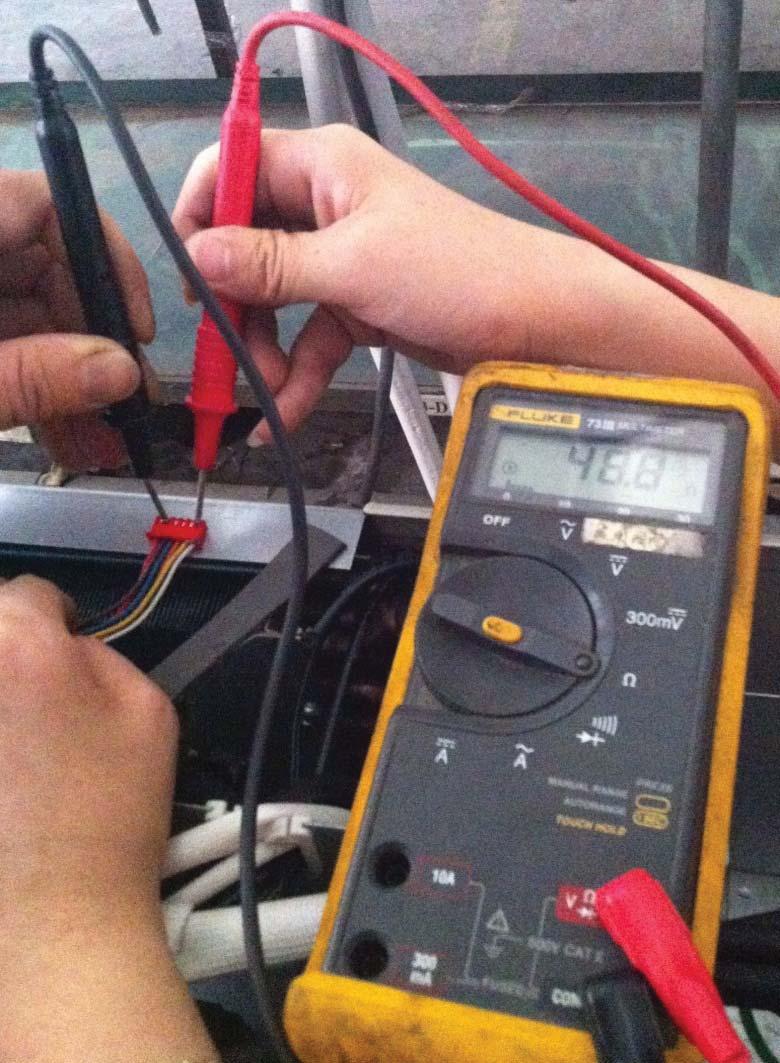
69 EXV Check (CONT) Brown-Orange Brown-White 69


 Turn off the air conditioner and turn off")
 Remove the screws of air outlet grille (4")
 Remove the fan.")
70 DISASSEMBLY INSTRUCTIONS SIZE 18 NOTE: This section is for reference and the photos may have differ slightly from your unit.. Part name Procedures Remarks 1 Fan assembly How to remove the fan assembly. 1) Turn off the air conditioner and turn off the power breaker. 2) Remove the screws of air outlet grille (4 screws). 3) Remove hex nut securing the fan. 4) Remove the fan. Screws of top 5) Remove the top cover screws, and remove the top cover. (3 screws) 70
 Disconnect the fan motor connector CN14 (3p, white) from the IPM board.")

71 DISASSEMBLY INSTRUCTIONS SIZE 18 (CONT) 6) Remove the electrical control box cover. 7) Disconnect the fan motor connector CN14 (3p, white) from the IPM board. 8) Remove the fan motor after unfastening the four screws. 2 Panel plate How to remove the panel plate. Front panel screws 1) Remove the front panel screws then remove the front panel (6 screws). Front panel screws 71
 Remove the big handle Front panel")
.")
, then")

72 DISASSEMBLY INSTRUCTIONS SIZE 18 (CONT) 2) Remove the big handle Front panel screws screws, and remove the big handle (4 screws). 3) Remove the terminal board screws (2) and the right-rear panel screws (7), then remove the right rear panel. Big handle screws Terminal board screws Right-rear panel screws Right-rear panel screws 72
 Unfasten the reactor connector. 4) Unfasten the compressor connector.")
73 DISASSEMBLY INSTRUCTIONS SIZE 18 (CONT) 3 Electrical parts How to remove the electrical parts. 1) Complete the steps in sections 1 & 2. 2) Remove the four (4) screws securing the IPM board. IPM board PCB board 3) Unfasten the reactor connector. 4) Unfasten the compressor connector. 5) Disconnect the following three (3) connection wires and connectors between the IPM and the main control PCB: CN1(5p,white) CN14(3p,white) CN4(red or brown) CN5(blue) 6) Remove the IPM board. 7) Disconnect the connectors and wires connected from PCB and other parts. 73
 CN7:")
 CN18/CN19: Electronic expansive valve A,B (6p/6p,red/red)")
 CN1/CN2 CN5/CN6 CN3 CN4 CN5/CN6: Crankcase heating cable")
 after removing the big handle and the right-rear")
74 DISASSEMBLY INSTRUCTIONS SIZE 18 (CONT) Connectors: CN17 CN15 CN7 CN18/CN19 CN25/CN23 CN17:T3/T4 temperature sensor (2p/2p,white) CN7: Discharge temperature (2p,white) CN15:T2B-A,B temperature sensor (2p/2p,white) CN18/CN19: Electronic expansive valve A,B (6p/6p,red/red) CN25/CN23: S-A,S-B (3p/3p,white/white) Wires: CN1/CN2: 4-way valve (blue-blue) CN1/CN2 CN5/CN6 CN3 CN4 CN5/CN6: Crankcase heating cable (red-red) CN3:L-IN (red) CN4:N-IN (black) 8) Disconnect the grounding wire (yellow-green) after removing the big handle and the right-rear panel. 9) Remove the PCB board. 74
75 DISASSEMBLY INSTRUCTIONS SIZE 18 (CONT) 4 Compressor How to remove the compressor. 1) Complete steps in section 1 & 2. 2) Remove the electrical control box cover. 3) Extract the refrigerant gas. 4) Remove the sound insulation material and crankcase heating cable. 5) Remove the compressor terminal cover and disconnect the crankcase electric heater and compressor from the terminal. 6) Remove the discharge pipe and suction pipe with a burner. 7) Remove the hex nuts and washers securing the compressor to the bottom plate. 8) Lift the compressor. 75
 screws and remove the reactor. Inductance cover screws 6 The 4-way valve How to remove the 4-way valve 1) Complete steps in section 2. 2) Extract the refrigerant gas.")
76 DISASSEMBLY INSTRUCTIONS SIZE 18 (CONT) 5 Reactor How to remove the reactor 1) 2) 3) Complete steps in section 2. Unfasten the connector between the IPM and the reactor. Remove the reactor s three (3) screws and remove the reactor. Inductance cover screws 6 The 4-way valve How to remove the 4-way valve 1) Complete steps in section 2. 2) Extract the refrigerant gas. 3) Remove the electrical parts (see section 3). Coil Welded parts 4) Remove the screw securing the coil and remove the coil. 5) Detach the welded parts of the 4-way valve and pipe. 76
 Remove the electrical parts from section 3.")

 Turn off the air conditioner. Turn off the power breaker.")
 Remove the top cover screws and remove the top cover.")
77 DISASSEMBLY INSTRUCTIONS SIZE 18 (CONT) 7 The expansion valve How to remove the expansion valve 1) Complete the steps in sections 1 & 2. 2) Remove the electrical parts from section 3. 3) Remove the coils. 4) Detach the welded parts of the expansion valves and pipes. Expansion valves Coils DISASSEMBLY INSTRUCTIONS SIZE 24. Part name Procedures Remarks 1 Panel plate How to remove the panel plate. Big handle screws Top cover screws 1) Turn off the air conditioner. Turn off the power breaker. 2) Remove the big handle screws (4), then remove the big handle. 3) Remove the top cover screws and remove the top cover. Top cover screws 4) Remove the right-front side panel screws and remove the right front side panel (1 screws). 5) Remove the front panel screws (8) and remove the front panel. 77
78 DISASSEMBLY INSTRUCTIONS SIZE 24 (CONT) Front panel screws Right front side panel screws 6) Remove the terminal board screws (2), the water collector screws, and the right-rear panel screws (15) and then remove the right-rear panel. Front panel screws Front panel screws Front panel screws 78

79 DISASSEMBLY INSTRUCTIONS SIZE 24 (CONT) Right-rear panel screws Terminal board screws 79

. 2) Remove the hex nut securing the fan.")
 Disconnect the fan motor connector CN14 (5p,white) from the IPM")
80 DISASSEMBLY INSTRUCTIONS SIZE 24 (CONT) How to remove the fan 2 Fan assembly assembly. 1) Remove the top cover, right front side panel and the front panel (see section 1, steps 1-4). 2) Remove the hex nut securing the fan. 3) Remove the fan. 4) Remove the electrical control box. 5) Disconnect the fan motor connector CN14 (5p,white) from the IPM board. 6) Remove the four screws securing the fan motor then remove the fan motor. 80
 Complete the steps in sections 1 & 2. 2) Remove the four screws (4) securing the IPM board.")
 Disconnect the following connection wires and connectors between the IPM and the PCB:")
81 DISASSEMBLY INSTRUCTIONS SIZE 24 (CONT) 3 Electrical parts How to remove the electrical parts. 1) Complete the steps in sections 1 & 2. 2) Remove the four screws (4) securing the IPM board. 3) Unfasten the reactor connector. 4) Unfasten the compressor connector. IPM board PCB board 5) Disconnect the following connection wires and connectors between the IPM and the PCB: CN1(5p,white) CN14(3p,white) CN3(red or brown) CN5(blue) 6) Remove the IPM board. 81
 CN7: Discharge temperature sensor (2p,white) CN17 CN15 CN7 CN18/CN19/CN22 CN12:Ttop temperature sensor(2p,white) CN15:T2B-A,B,C temperature")
82 DISASSEMBLY INSTRUCTIONS SIZE 24 (CONT) 7) Disconnect the connectors and wires connected to the PCB and other parts. Connectors: CN17:T3/T4 temperature sensor (2p/2p,white) CN7: Discharge temperature sensor (2p,white) CN17 CN15 CN7 CN18/CN19/CN22 CN12:Ttop temperature sensor(2p,white) CN15:T2B-A,B,C temperature sensor (2p/2p/2p,white) CN18/CN19/CN22: Electronic expansive valve A,B,C (6p/6p/6p,red/red/red) CN20 CN23 CN25 CN3 CN4 CN25/CN23/CN20: S-A,S-B,S-C (3p/3p/3p,white/white/white) Wires: CN1/CN2: 4-way valve (blue-blue) CN5/CN6: Crankcase heating cable (red-red) CN3:L1-IN (red) CN4:L2-IN (black) CN1/CN2 CN5/CN6 8) Disconnect the grounding wire (yellow-green) after removing the big handle and the right-rear panel. 9) Remove the PCB board. 82
 Extract the refrigerant gas. 4) Remove the sound insulation material and crankcase heating cable.")
83 DISASSEMBLY INSTRUCTIONS SIZE 24 (CONT) 4 Compressor How to remove the compressor 1) Complete steps in sections 1, 2, and 3. 2) Remove the electrical control box and partition plate. 3) Extract the refrigerant gas. 4) Remove the sound insulation material and crankcase heating cable. 5) Remove the compressor terminal cover, the compressor thermo disconnect wires and the compressor from the terminal. 6) Remove the discharge pipe and the suction pipe with a burner. 7) Remove the hex nuts and washers securing the compressor to the bottom plate. 8) Lift the compressor. 83
 Remove the inductance cover screws (2) then remove the inductance cover. 4) Disconnect the two wires connected to the inductance cover.")
 Complete the steps in sections 1 and 2. 2) Extract the refrigerant gas.")
84 DISASSEMBLY INSTRUCTIONS SIZE 24 (CONT) 5 Reactor How to remove the reactor 1) Compete the steps in sections 1 & 2. 2) Unfasten the connector between the IPM and the reactor. 3) Remove the inductance cover screws (2) then remove the inductance cover. 4) Disconnect the two wires connected to the inductance cover. Inductance cover screws 5) Remove the four (4) reactor screws, then remove the reactor. Reactor screws 6 The 4-way valve How to remove the 4-way valve 1) Complete the steps in sections 1 and 2. 2) Extract the refrigerant gas. Coil Welded parts 3) Remove the electrical parts (see section 3). 4) Remove the screw securing the coil then remove the coil. 5) Detach the welded parts of the 4-way valve and pipe. 84
 Remove the electrical parts (see section 3). 3) Remove the coils.")

 Remove the big handle screws.")
85 DISASSEMBLY INSTRUCTIONS SIZE 24 (CONT) 7 The expansion valve How to remove the expansion valve 1) Complete steps in sections 1 and 2. 2) Remove the electrical parts (see section 3). 3) Remove the coils. Expansion valves 4) Detach the welded parts of the expansion valves and the pipes. DISASSEMBLY INSTRUCTIONS SIZE 30. Part name Procedures Remarks 1 Panel plate How to remove the panel plate. Big handle screws 1) Turn off the air conditioner. Turn off the power breaker. Top cover screws 2) Remove the big handle screws. 3) Remove the top cover screws and then remove the top cover (4 screws). Top cover screws 4) Remove the right front side panel screws, and then remove the right front side panel (1 screw). 85
 and remove the front panel.")
, the water collector screws,")

86 DISASSEMBLY INSTRUCTIONS SIZE 30 (CONT) 5) Remove the front panel screws (8) and remove the front panel. Front panel screws Right front side panel screws 6) Remove the terminal board screws (2), the water collector screws, and the right-rear panel screws (15), and then remove the right-rear panel. Front panel screws Front panel screws Front panel screws 86
 Remove the top cover, right front side panel and the front panel from section 1 steps 1-4. 2) Remove the hex nut securing the fan.")
87 DISASSEMBLY INSTRUCTIONS SIZE 30 (CONT) Right-rear panel screws Terminal board screws 2 Fan assembly How to remove the fan assembly 1) Remove the top cover, right front side panel and the front panel from section 1 steps ) Remove the hex nut securing the fan. 87
 Disconnect the fan motor connector CN19(3P, white) from the driver board. 6) Remove the screws (4) and then remove the fan motor. How to remove the electrical 3 Electrical parts parts.")
88 DISASSEMBLY INSTRUCTIONS SIZE 30 (CONT) 3) Remove the fan. 4) Undo the hooks, remove the screws, and then open the electrical control box. 5) Disconnect the fan motor connector CN19(3P, white) from the driver board. 6) Remove the screws (4) and then remove the fan motor. How to remove the electrical 3 Electrical parts parts. 1) Complete steps of sections 1 and 2. 2) Remove the connector. 3) Remove the compressor connector. 4) Remove the PFC inductor connector. Driver board PCB board 88
 CN54-CN6(red) CN53-CN5(black) 6) Remove the screws then remove the driver board.")
 CN33: Discharge temperature sensor (2p,white)")
 CN30/CN29/CN28/CN27: S-A,S-B,S- C,S-D (3p/3p/3p/3p,white) CN30/")
89 DISASSEMBLY INSTRUCTIONS SIZE 30 (CONT) 5) Disconnect the following three connection wires between the driver board and PCB. CN55-CN7(7p,white) CN54-CN6(red) CN53-CN5(black) 6) Remove the screws then remove the driver board. 7) Disconnect the connectors and wires from the PCB and other parts. CN53 CN54 Connectors: CN8:T3/T4 temperature sensor (2p/2p,white) CN33: Discharge temperature sensor (2p,white) CN13:T2B-A,B,C,D temperature sensor (2p/2p/2p/2p,white) CN55 CN18/CN17/CN21/CN20 CN18/CN17/CN21/CN20: Electronic expansive valve A,B,C,D (6p/6p/6p,red/red/red) CN30/CN29/CN28/CN27: S-A,S-B,S- C,S-D (3p/3p/3p/3p,white) CN30/ CN29/ CN9: High and low pressure switch (2p/2p, white) CN8 CN9 89
 CN10/CN44: Crankcase heating cable (black-red) CN1:L1-IN")
 after removing the right-rear panel. 9) Remove the PCB board.")
 Remove the electrical control box and the partition plate. 3) Extract the refrigerant gas.")
 Remove the compressor terminal cover, disconnect the compressor thermo wires, and")
90 DISASSEMBLY INSTRUCTIONS SIZE 30 (CONT) Wires: CN3/CN22: 4-way valve (blue-blue) CN4/CN40: Crankcase heating cable (black-red) CN10/CN44: Crankcase heating cable (black-red) CN1:L1-IN (red) CN2:L2-IN (black) CN3 CN4 CN10 CN22 CN40 CN44 CN13 CN33 CN2 CN1 8) Disconnect the grounding wire (yellow-green) after removing the right-rear panel. 9) Remove the PCB board. How to remove the compressor. 4 Compressor 1) Complete the steps in sections 1, 2, and 3. 2) Remove the electrical control box and the partition plate. 3) Extract the refrigerant gas. 4) Remove the sound insulation material and the crankcase heating cable. 5) Remove the compressor terminal cover, disconnect the compressor thermo wires, and disconnect the compressor from the terminal. 90
91 DISASSEMBLY INSTRUCTIONS SIZE 30 (CONT) 6) Remove the discharge pipe and suction pipe with a burner. 7) Remove the hex nuts and washers securing the compressor to the bottom plate. 8) Lift the compressor. 5 The 4-way valve How to remove the 4-way valve 1) Perform work of item 1,2. 2) Extract the refrigerant gas. 3) Remove the electrical parts (see section 3). 4) Remove the coil screw and remove the coil. 5) Detach the welded parts of the 4-way valve and pipe. Coil Welded parts 6 The expansion valve How to remove the expansion valve 1) Complete the steps of sections 1 and 2. 2) Remove the electrical parts (see section 3). 3) Remove the coils. Expansion valves 4) Detach the welded parts of the expansion valves and the pipes. 91


.")
 Remove the fan.")
92 DISASSEMBLY INSTRUCTIONS SIZE 36 AND 48 Part name Procedures Remarks 1 Fan assembly How to remove the fan assembly. 1) Turn off the air conditioner. Turn off the power breaker. 2) Remove the air outlet grille screws (8). 3) Remove the hex nut securing the fan. 4) Remove the fan. Top screws 5) Remove the top screws (4) and then remove the top cover. 92
, and then remove the front side panel.")


93 DISASSEMBLY INSTRUCTIONS SIZE 36 AND 48 (CONT) 6) Remove the front side panel screw (1), and then remove the front side panel. 7) Disconnect the fan motor connectors FAN1(3p,white) and FAN2(3p,white) from the DC motor driver board. 8) Remove the fan screws and remove the fan motor. 2 Panel plate How to remove the panel plate. 1) Remove the big handle screws (2), then remove the big handle and the water collector. Big handle screws Water collector screws 93
 and the right-rear panel")


94 DISASSEMBLY INSTRUCTIONS SIZE 36 AND 48 (CONT) 2) Remove the terminal board screws (2) and the right-rear panel screws (15) and then remove the right-rear panel. Terminal Board Screws Right-rear panel screws Right-rear panel screws 3 Electrical parts How to remove the electrical parts. 1) Complete steps 5 and 6 from section 1 and all the steps from section 2. IPM board PCB board DC Fan Driver board 2) Disconnect the fan motor connector (5p,white) from the IPM board. 94

 Disconnect the connectors and wires connected from the PCB and the other parts.")
 CN11:T2B-A,B,C,D,E temperature")
95 DISASSEMBLY INSTRUCTIONS SIZE 36 AND 48 (CONT) 3) Disconnect the following connection wires and connectors between the IPM and the other parts. CN2(yellow) CN1(red) CN6(black) CN3(yellow) UVW(black) CN9(10p,white) 4) Remove the screws and then remove the IPM board. 5) Disconnect the connectors and wires connected from the PCB and the other parts. CN3 CN1 Connectors: CN8: Discharge temperature sensor (2p,white) CN12Heatsink temperature sensor(2p,red) CN13 CN16 CN21 CN29 CN37 CN8 CN12 CN9 CN11 CN9:T3/T4 temperature sensor (2p/2p,white) CN11:T2B-A,B,C,D,E temperature sensor (2p/2p/2p/2p/2p,white) CN15/CN23/CN26/CN30/CN33: Electronic expansive valve (6p/6p/6p/6p/6p,red) 95
 CN10: High and low pressure switch (2p/2p,")

 CN3:N-IN (black) 6) Disconnect the grounding wire")
 Complete steps 5 and 6 in section 1 and")
 Remove the sound insulation material and the crankcase heating cable.")
96 DISASSEMBLY INSTRUCTIONS SIZE 36 AND 48 (CONT) CN37/CN29/CN21/CN16/CN13: S- A,S-B,S-C,S-D,S-E (3p/3p/3p/3p/3p,white) CN10: High and low pressure switch (2p/2p, white) Wires: CN17/CN18: 4-way valve (blue-blue) CN10 CN30/CN23 CN19/CN20: connected to crankcase heating cable. (black-red) CN24/CN25: Electric heater of chassis (orange-orange) CN17/CN18 CN19/CN20 CN24/CN25 CN1:L-IN (red) CN3:N-IN (black) 6) Disconnect the grounding wire (yellow-green) after removing the big handle. 7) Remove the PCB board. 4 Compressor How to remove the compressor 1) Complete steps 5 and 6 in section 1 and all the steps in section 2. 2) Extract the refrigerant gas. 3) Remove the sound insulation material and the crankcase heating cable. 4) Remove the compressor terminal cover disconnect the crankcase electric heater wires and compressor from the terminal. 96
97 DISASSEMBLY INSTRUCTIONS SIZE 36 AND 48 (CONT) 5) Remove the discharge pipe and suction pipe with a burner. 6) Remove the hex nuts and washers securing the compressor to the bottom plate. 7) Lift the compressor. 5 The 4-way valve How to remove the 4-way valve 1) Complete steps 5 and 6 from section 1 and all the steps from section 2. 2) Extract the refrigerant gas. 3) Remove the electrical parts (see section 3) Coil Welded parts 4) Remove the coil screw and remove the coil. 5) Detach the welded parts of the 4-way valve and pipe. 97
 Remove the electrical parts (see section 3). 3) Remove the coil. 4) Detach the welded parts of the expansion valves and the pipes. Copyright 2016 CAC/BDP. 7310 W. Morris St.")
98 DISASSEMBLY INSTRUCTIONS SIZE 36 AND 48 (CONT) 6 The expansion valve How to remove the expansion valve 1) Complete the steps in sections 1 and 2. Expansion valves 2) Remove the electrical parts (see section 3). 3) Remove the coil. 4) Detach the welded parts of the expansion valves and the pipes. Copyright 2016 CAC/BDP W. Morris St. Indianapolis, IN Edition Date: 07/16 Manufacturer reserves the right to change, at any time, specifications and designs without notice and without obligations. Catalog.38MGR-01SM Replaces: NEW 98
Installation Instructions
 38MHR Outdoor Unit Single Zone Ductless System Sizes 09 to 24 Installation Instructions NOTE: Read the entire instruction manual before starting the installation. NOTE: Images are for illustration purposes
Product Data INDUSTRY LEADING FEATURES / BENEFITS
 8MGR Multi-zone Outdoor Unit Ductless System Sizes 18, 24, 0, 6 and 48 Fig. 1 18K Fig. 2 24K and 0K Product Data INDUSTRY LEADING FEATURES / BENEFITS A competitively priced and creative solution to design
DLCLRA. INSTALLATION INSTRUCTIONS Outdoor Unit Single Zone Ductless System Sizes 36 to 58 TABLE OF CONTENTS
 DLCLRA INSTALLATION INSTRUCTIONS Outdoor Unit Single Zone Ductless System Sizes 36 to 58 Fig. 1 - Size 36 TABLE OF CONTENTS PAGE SAFETY CONSIDERATIONS... 2 PARTS LIST... 3 SYSTEM REQUIREMENTS... 4 WIRING...
Installation Instructions
 38MPRA Outdoor Unit Single Zone Ductless System Sizes 09 to 12 Installation Instructions NOTES: Read the entire instruction manual before starting the installation. Images are for illustration purposes
Installation Instructions
 38MGQ Multi-Zone Ductless System Sizes 18, 27, 36 and 48 Installation Instructions NOTE: Read the entire instruction manual before starting the installation. TABLE OF CONTENTS PAGE SAFETY CONSIDERATIONS...
Installation Instructions
 38MGR Multi-zone Outdoor Unit Ductless System Sizes 18, 24, 30, 36 and 48 Installation Instructions TABLE OF CONTENTS PAGE SAFETY CONSIDERATIONS... 2 GENERAL... 2 PARTS LIST... 3 SYSTEM REQUIREMENTS...
DLCSRA. INSTALLATION INSTRUCTIONS Outdoor Unit Ductless Split System Sizes 09 to 36 TABLE OF CONTENTS
 DLCSRA INSTALLATION INSTRUCTIONS Outdoor Unit Ductless Split System Sizes 09 to 36 NOTES: Read the entire instruction manual before starting the installation. Images are for illustration purposes only.
Product Data INDUSTRY LEADING FEATURES / BENEFITS
 8MGR Multi-zone Outdoor Unit Ductless System Sizes 18, 24, 0, 6 and 48 Fig. 1 18K Fig. 2 24K and 0K Product Data INDUSTRY LEADING FEATURES / BENEFITS A competitively priced and creative solution to design
DLCMRA. INSTALLATION INSTRUCTIONS Multi zone Outdoor Unit Ductless System Sizes 18, 27, 36 and 48 TABLE OF CONTENTS PAGE SAFETY CONSIDERATIONS...
 DLCMRA INSTALLATION INSTRUCTIONS Multi zone Outdoor Unit Ductless System Sizes 18, 27, 36 and 48 TABLE OF CONTENTS PAGE SAFETY CONSIDERATIONS... 2 GENERAL... 2 PARTS LIST... 3 SYSTEM REQUIREMENTS... 4
TABLE OF CONTENTS. NOTE: Read the entire instruction manual before starting the installation. TROUBLESHOOTING... 13
 R 410A Duct Free Split System Air Conditioner and Heat Pump Product Family: DFS4(A/H) System, DFC4(A/H)3 Outdoor, DFF4(A/H)H Indoor NOTE: Read the entire instruction manual before starting the installation.
Installation Instructions
 8GXM / 0GXM Multi---Split High---Wall Duct Free Split System 8GXM --- Size 18k, k, and 0k 0GXM --- Size 9k, 1k, and 18k Installation Instructions NOTE: Read the entire instruction manual before starting
Installation Instruction
 40GRQ / 619FB / 38GRQ / 538FR High- Wall Ductless Split System Sizes 09-18 Installation Instruction NOTE: Read the entire instruction manual before starting the installation. TABLE OF CONTENTS PAGE SAFETY
Installation Instructions
 40MBFQ Floor Console Ductless System Sizes 09 to 58 Installation Instructions TABLE OF CONTENTS PAGE SAFETY CONSIDERATIONS... 2 PARTS LIST... 3 SYSTEM REQUIREMENTS... 4 WIRING... 4 DIMENSIONS... 5 CLEARANCES...
Installation Instructions
 40MAQ / 38MAQ 619PB / 538PR High---Wall Ductless Split System Sizes 09 to 30 Installation Instructions TABLE OF CONTENTS PAGE PARTS LIST... 2 SAFETY CONSIDERATIONS... 3 SYSTEM REQUIREMENTS... 4 DIMENSIONS...
Installation Instructions
 40MAQ High Wall Ductless Split System Sizes 09 to 36 Installation Instructions NOTE: Read the entire instruction manual before starting the installation TABLE OF CONTENTS PAGE SAFETY CONSIDERATIONS 2 PARTS
Installation Instructions
 40MBFQ Floor Console Ductless System Sizes 09 to 12 Installation Instructions TABLE OF CONTENTS PAGE SAFETY CONSIDERATIONS... 2 PARTS LIST... 3 SYSTEM REQUIREMENTS... 4 DIMENSIONS... 5 CLEARANCES... 5
Installation Instruction
 DLFCAB / DLCCAR / DLFCHB / DLCCHR DLFDAB / DLCDAR / DLFDHB / DLCDHR High- Wall Ductless Split System Sizes 09-36 Installation Instruction NOTE: Read the entire instruction manual before starting the installation.
INSTALLATION INSTRUCTIONS R 410A
 R 410A Ductless Split System Air Conditioner and Heat Pump MODELS: DLC4(A/H) Outdoor, DLF4(A/H) SIZES: 9K, 12K, 18K, 24K, 30K, and 36K NOTE: Read the entire instruction manual before starting the installation.
Product Data INDUSTRY LEADING FEATURES / BENEFITS. 38MBQ Outdoor Unit Single Zone Ductless System Sizes 36 to 48
 38MBQ Outdoor Unit Single Zone Ductless System Sizes 36 to 48 Product Data INDUSTRY LEADING FEATURES / BENEFITS A PERFECT BALANCE BETWEEN BUDGET LIMITS, ENERGY SAVINGS AND COMFORT. The 38MBQ series ductless
Product Data. 38MAQ Outdoor Unit Single Zone Ductless System Sizes 09 to 30 INDUSTRY LEADING FEATURES / BENEFITS
 38MAQ Outdoor Unit Single Zone Ductless System Sizes 09 to 30 Product Data INDUSTRY LEADING FEATURES / BENEFITS A PERFECT BALANCE BETWEEN BUDGET LIMITS, ENERGY SAVINGS AND COMFORT. The 38MAQ series ductless
Installation Instructions
 40MBD Ducted Style Ductless System Sizes 09 to 48 Installation Instructions NOTE: Read the entire instruction manual before starting the installation. TABLE OF CONTENTS PAGE SAFETY CONSIDERATIONS... 2
Service Manual CAUTION ! WARNING SAFETY CONSIDERATIONS INTRODUCTION. 38MA*R Outdoor Unit Single Zone Ductless System Sizes 09 to 36
 38MA*R Outdoor Unit Single Zone Ductless System Sizes 09 to 36 Service Manual TABLE OF CONTENTS PAGE SAFETY CONSIDERATIONS... 1 INTRODUCTION... 1 MODEL / SERIAL NUMBER NOMENCLATURES... 2 SPECIFICATIONS...
Installation Instructions
 40MAQ High Wall Ductless System Sizes 09 to 36 Installation Instructions NOTES: Read the entire instruction manual before starting the installation. Images are for illustration purposes only. Actual models
Service Manual CAUTION ! WARNING INTRODUCTION. 619PB High Wall Ductless System Sizes 09 to 36
 619PB High Wall Ductless System Sizes 09 to 36 Service Manual TABLE OF CONTENTS PAGE SAFETY CONSIDERATIONS... 1 INTRODUCTION... 1 MODEL/SERIAL NUMBER NOMENCLATURES... 2 SPECIFICATIONS... 3 COMPATIBILITY...
MULTI INVERTER SERIE H6M
 MULTI INVERTER SERIE H6M Service manual www.mundoclima.com Thank you very much for purchasing our products. Please read this manual carefully before installing and using the unit. ODMFI-B1-1606 CL20440
CAUTION DLCPRA. SERVICE MANUAL Outdoor Unit Single Zone Ductless System Sizes 09 to 12 ! WARNING
 DLCPRA SERVICE MANUAL Outdoor Unit Single Zone Ductless System Sizes 09 to 12 TABLE OF CONTENTS PAGE SAFETY CONSIDERATIONS... 1 INTRODUCTION... 1 MODEL / SERIAL NUMBER MENCLATURES... 2 SPECIFICATIONS HEAT
Product Data INDUSTRY LEADING FEATURES / BENEFITS. 38MA*R Outdoor Unit Single Zone Ductless System Sizes 09 to 36
 38MA*R Outdoor Unit ingle Zone Ductless ystem izes 09 to 36 Product Data INDUTRY LEADING FEATURE / BENEFIT A PERFECT BALANCE BETWEEN BUDGET LIMIT, ENERGY AVING AND COMFORT. The 38MA*R series ductless systems
Installation Instructions
 40MHH High Wall Ductless System Sizes 09 to 24 Installation Instructions NOTE: Read the entire instruction manual before starting the installation. NOTE: Images are for illustration purposes only. Actual
Product Data. 38MGQ Multi-Zone Ductless System Sizes 18, 27, 36 and 48 INDUSTRY LEADING FEATURES / BENEFITS
 38MGQ Multi-Zone Ductless ystem izes 18, 27, 36 and 48 Product Data INDUTRY LEADING FEATURE / BENEFIT AN INEXPENIVE AND CREATIVE OLUTION TO DEIGN PROBLEM. The 38MGQ ductless inverter driven multi zone
Multi zone Two, Three, Four and Five Zones
 MULTI SPLIT SYSTEM OUTDOOR UNITS SERVICE MANUAL Multi zone Two, Three, Four and Five Zones DC INVERTER MULTI ZONE OUTDOOR UNITS Revision A: ODMI E 1601 PDB55/2016 Model Numbers: YN020GMFI22M2D YN030GMFI22M3D
Product Data INDUSTRY LEADING FEATURES / BENEFITS. 38MHR Outdoor Unit Single Zone Ductless System Sizes 09 to 24
 38MHR Outdoor Unit ingle Zone Ductless ystem izes 09 to 24 Product Data INDUTRY LEADING FEATURE / BENEFIT A PERFECT BALANCE BETWEEN BUDGET LIMIT, ENERGY AVING AND COMFORT. The 38MHR series ductless systems
CAUTION DLFEHA. SERVICE MANUAL High Wall Ductless System Sizes 09 to 24
 DLFEHA SERVICE MANUAL High Wall Ductless System Sizes 09 to 24 TABLE OF CONTENTS PAGE SAFETY CONSIDERATIONS... 1 INTRODUCTION... 1 MODEL/SERIAL NUMBER NOMENCLATURES... 2 SPECIFICATIONS COOLING ONLY...
Service Manual CAUTION
 38MHR Outdoor Unit Single Zone Ductless System Sizes 09 to 24 Service Manual TABLE OF CONTENTS PAGE SAFETY CONSIDERATIONS... 1 INTRODUCTION... 1 MODEL/SERIAL NUMBER NOMENCLATURES... 2 SPECIFICATIONS...
KMIR218-H221 / KMIR327-H217 / KMIR436-H217 / KMIR545-H219
 Multi outdoor units SERVICE MANUAL Multi - Zone heat pump units Model Numbers: KMIR218-H221 / KMIR327-H217 / KMIR436-H217 / KMIR545-H219 Table of Contents 1. Indoor Unit Combination 2. Suggested Indoor
HEAT PUMP INSTALLATION MANUAL
 DUCTLESS INVERTER HEAT PUMP INSTALLATION MANUAL Models: TERRA09HP230V1A TERRA12HP230V1A TERRA18HP230V1B TERRA24HP230V1B Thank you for choosing a Gree Terra Ductless Heat Pump for your customer. Please
CAUTION DLFPHA. SERVICE MANUAL High Wall Ductless System Sizes 09 to 12 ! WARNING
 DLFPHA SERVICE MANUAL High Wall Ductless System Sizes 09 to 12 TABLE OF CONTENTS PAGE SAFETY CONSIDERATIONS... 1 INTRODUCTION... 1 MODEL/SERIAL NUMBER MENCLATURES... 2 SPECIFICATIONS... 3 COMPATIBILITY...
Product Data. DLCERA Outdoor Unit Single Zone Ductless System Sizes 09 to 24 INDUSTRY LEADING FEATURES / BENEFITS
 DLCERA Outdoor Unit ingle Zone Ductless ystem izes 09 to 24 Product Data INDUTRY LEADING FEATURE / BENEFIT NOTE: Images are for illustration purposes only. Actual models may differ slightly. TABLE OF CONTENT
Multi zone. MULTI OUTDOOR UNITsS. CONDENsSING UNITsS. Revision V1.0: Table of Contents
 MULTI OUTDOOR UNITsS sservice MANUAL Multi zone CONDENsSING UNITsS Revision V1.0: 20160616 Table of Contents 1. Indoor Unit Combination 2. Suggested Indoor Unit Model Numbers 3. Dimension Of Outdoor Unit
Installation Instructions
 40MBCQ Cassette Ductless System Sizes 09 to 8 Installation Instructions TABLE OF CONTENTS PAGE SAFETY CONSIDERATIONS... PARTS LIST... 3 SYSTEM REQUIREMENTS... 4 DIMENSIONS INDOOR... 5 CLEARANCES INDOOR...
Installation Instructions
 24AHA4 Performance Series Air Conditioner with Puron Refrigerant 1-1/2 to 5 Nominal Tons Installation Instructions Fig. 1-24AHA4 A07532 SAFETY CONSIDERATIONS Improper installation, adjustment, alteration,
Residential Piping and Long Line Guideline
 AC / HP R-410A Refrigerant Systems Single-Stage, Two-Stage and Variable Speed Models Residential Piping and Long Line Guideline TABLE OF CONTENTS Safety Considerations... 2 Definitions... 2 Introduction...
Product Data INDUSTRY LEADING FEATURES / BENEFITS. 38MPRA Outdoor Unit Single Zone Ductless System Sizes 09 to 12
 38MPRA Outdoor Unit ingle Zone Ductless ystem izes 09 to 12 Product Data INDUTRY LEADING FEATURE / BENEFIT A PERFECT BALANCE BETWEEN BUDGET LIMIT, ENERGY AVING AND COMFORT. The ductless systems are a matched
Service Manual CAUTION. 38MAQ Outdoor Unit Single Zone Ductless System Sizes 09 to 30 ! WARNING SAFETY CONSIDERATIONS
 38MAQ Outdoor Unit Single Zone Ductless System Sizes 09 to 30 TABLE OF CONTENTS PAGE SAFETY CONSIDERATIONS... 1 INTRODUCTION... 1 MODEL/SERIAL NUMBER NOMENCLATURES... 2 SPECIFICATIONS... 3 DIMENSIONS...
WMHP Series R410a Heat Pump INSTALLATION INSTRUCTIONS
 WMHP Series R410a Heat Pump INSTALLATION INSTRUCTIONS **WARNING TO INSTALLER, SERVICE PERSONNEL AND OWNER** Altering the product or replacing parts with non authorized factory parts voids all warranty
Service Manual CAUTION ! WARNING SAFETY CONSIDERATIONS INTRODUCTION 619PB / 538PR HIGH-WALL DUCTLESS SPLIT SYSTEM SIZES 09 TO 30
 619PB / 538PR HIGH-WALL DUCTLE PLIT YTEM IZE 09 TO 30 TABLE OF CONTENT PAGE AFETY CONIDERATION... 1 INTRODUCTION... 1 MODEL / ERIAL NUMBER NOMENCLATURE... 2 TANDARD FEATURE AND ACCEORIE... 3 DIMENION-
Product Data. 38GJQ MULTI-ZONE DUCTLESS SYSTEM MATCHED WITH 40GRQ / 40GJB / 40GJC / 40GJD / 40GJF Indoor Units Sizes 18, 24, 30, 36, 42, 48 and 56
 38GJQ MULTI-ZONE DUCTLESS SYSTEM MATCHED WITH 40GRQ / 40GJB / 40GJC / 40GJD / 40GJF Indoor Units Sizes 18, 24, 30, 36, 42, 48 and 56 Product Data INDUSTRY LEADING FEATURES / BENEFITS AN INEXPENSIVE AND
Service Manual CAUTION. 40MBDQ Ducted Style Ductless System Sizes 18 to 48 ! WARNING
 40MBDQ Ducted Style Ductless System Sizes 18 to 48 Service Manual TABLE OF CONTENTS PAGE SAFETY CONSIDERATIONS... 1 INTRODUCTION... 1 MODEL SERIAL NUMBER NOMENCLATURES... 2 SPECIFICATIONS... 3 COMPATIBILITY...
Service Manual CAUTION ! WARNING SAFETY CONSIDERATIONS INTRODUCTION. 40MFC / 38MFC 40MFQ / 38MFQ High Wall Ductless System Sizes 09 to 22
 40MFC / 38MFC 40MFQ / 38MFQ High Wall Ductless ystem izes 09 to 22 TABLE OF CONTENT PAGE AFETY CONIDERATION... 1 INTRODUCTION... 1 MODEL / ERIAL NUMBER NOMENCLATURE... 2 TANDARD FEATURE AND ACCEORIE...
Installation Instructions
 PREFERREDT SERIES AIR CONDITIONER WITH PURONR REFRIGERANT 1-1/2 TO 5 NOMINAL TONS Installation Instructions Fig. 1 --- 538A NOTE: Read the entire instruction manual before starting the installation. TABLE
Product Data INDUSTRY LEADING FEATURES / BENEFITS. 38MHRB Outdoor Unit Single Zone Ductless System Sizes 09 to 24
 38MHRB Outdoor Unit ingle Zone Ductless ystem izes 09 to 24 Product Data INDUTRY LEADING FEATURE / BENEFIT A PERFECT BALANCE BETWEEN BUDGET LIMIT, ENERGY AVING AND COMFORT. The 38MHRB series ductless systems
R4H4. Product Specifications
 R4H4 Product Specifications EFFICIENT 14 SEER HEAT PUMP ENVIRONMENTALLY BALANCED REFRIGERANT 1-1/2 THRU 5 TONS SPLIT SYSTEM 208 / 230 Volt, 1- phase, 60 Hz REFRIGERATION CIRCUIT S Scroll compressors on
UP TO 17.5 SEER / 13.5 EER / 9.5 HSPF HEAT PUMP ENVIRONMENTALLY BALANCED R- 410A REFRIGERANT 2 THRU 5 TONS SPLIT SYSTEM
 EFFICIENT UP TO 17.5 SEER / 13.5 EER / 9.5 HSPF HEAT PUMP ENVIRONMENTALLY BALANCED R- 410A REFRIGERANT 2 THRU 5 TONS SPLIT SYSTEM 208/230 Volt 1- phase REFRIGERATION CIRCUIT S 2- stage scroll compressors
R4H4. Product Specifications
 ENVIRONMENTALLY SOUND REFRIGERANT R4H4 Product Specifications EFFICIENT 14 SEER HEAT PUMP ENVIRONMENTALLY SOUND R 410A REFRIGERANT 1 1/2 THRU 5 TONS SPLIT SYSTEM 208 / 230 Volt, 1 phase, 60 Hz REFRIGERATION
Installation Instructions Read and become familiar with these instructions before beginning installation.
 KSAIC020230 (208-230V) 24V Interface Kit for Ductless Outdoor Single Zone matched with Air Handler Installation Instructions Read and become familiar with these instructions before beginning installation.
Installation Instructions Read and become familiar with these instructions before beginning installation.
 KSAIC005 (5V) KSAIC00230 (208-230V) 24V Interface Kit for Ductless Systems Installation Instructions Read and become familiar with these instructions before beginning installation. SAFETY CSIDERATIS Read
N4H4. Product Specifications 14 SEER HEAT PUMP. ENVIRONMENTALLY SOUND R 410A REFRIGERANT 1½ THRU 5 TONS SPLIT SYSTEM 208 / 230 Volt, 1 phase, 60 Hz
 ENVIRONMENTALLY SOUND REFRIGERANT N4H4 Performance Series Product Specifications 14 SEER HEAT PUMP ENVIRONMENTALLY SOUND R 410A REFRIGERANT 1½ THRU 5 TONS SPLIT SYSTEM 208 / 230 Volt, 1 phase, 60 Hz REFRIGERATION
Fig. 1 - Unit PHD4 and WPH4
 OWNER S MANUAL 14 SEER Single -Package Heat Pump System with R -410A Refrigerant Single Phase and Three Phase 2 to 5 Nominal Tons PHD4 Series F and WPH4 Series B Fig. 1 - Unit PHD4 and WPH4 A09034 NOTE
For 18 SEER R410A Series Unitary Ducted Split AC
 For 18 SEER R410A Series Unitary Ducted Split AC Thermostat Owner's Manual Commercial Air Conditioners Thank you for choosing MRCOOL, please read this owner s manual carefully before operation and keep
Owner s Information Manual
 50EZ---A and 50VT ---A Comfort and Performance 13 and 14 SEER Single Packaged Heat Pump System With PuronR (R ---410A) Refrigerant Single and Three Phase 2---5 Nominal Tons (Sizes 24---60) Owner s Information
AIR-COOLED CONDENSING UNIT UNITS PRODUCED AFTER JANUARY, 1996 INDEX SCHEMATIC DIAGRAM FIG. NO.
 wiring diagrams AIR-COOLED CONDENSING UNIT 566D Sizes 120-240 Cancels: New WD 566D.120.1 11/15/96 UNITS PRODUCED AFTER JANUARY, 1996 INDEX UNIT 566D 120-240 ELECTRICAL CHARACTERISTICS (V-Ph-Hz) SCHEMATIC
Installation Instructions
 Performance Series Heat Pumps with PURONr Refrigerant 1 --- 1/2 to 5 Nominal Tons Installation Instructions Fig. 1 --- A07532 NOTE: Read the entire instruction manual before starting the installation.
Installation Instructions
 Installation Instructions EHMA SERIES ELECTRIC HEATERS FOR PAM3 SERIES PACKAGE AIR CONDITIONERS PHM3 SERIES PACKAGE HEAT PUMPS TABLE OF CONTENTS SAFE INSTALLATION REQUIREMENTS... 2 GENERAL INFORMATION...
Installation Instructions
 25HHA4 Performance Series Heat Pump with Puron Refrigerant 1-1/2 to 5 Nominal Tons Installation Instructions Fig. 1-25HHA4 A07532 SAFETY CONSIDERATIONS Improper installation, adjustment, alteration, service,
Bosch Split-Type Ductless Air Conditioner / Heat Pump
 Bosch Split-Type Ductless Air Conditioner / Heat Pump Climate 5000 AA Series Service Manual 2 Bosch Climate 5000 AA Series Split Type Ductless Air Conditioner / Heat Pump Service Manual Data subject to
Installation Instructions
 50ES--A, 50EZ--A, 50VG--A, B, 50VL--A, B, 50VR--A, 50VT--A, B 604D-- --A, 607C-- --A, B, 607E-- --A, 704D-- --A, 707C-- --A, B, 707E-- --A PA3G -- -- A, PH3G -- -- A, PA4G, PH4G PAD3, PHD3, PAD4, PHD4,
INSTALLATION INSTRUCTIONS
 INSTALLATION INSTRUCTIONS R 410A Ducted Horizontal Air Conditioner Product Family: HC4A3 Fig. 1 - HC4A3 NOTE: Read the entire instruction manual before starting the installation. TABLE OF CONTENTS PAGE
Product Data. 38MG / 40MA / 40MB Multi- Zone Ductless Split System Size 18k, 27k, 36k and 48k INDUSTRY LEADING FEATURES / BENEFITS
 38MG / 40MA / 40MB Multi- Zone Ductless plit ystem ize 18k, 27k, 36k and 48k Product Data INDUTRY LEADING FEATURE / BENEFIT AN INEXPENIVE AND CREATIVE OLUTION TO DEIGN PROBLEM. The 38MG / 40MA / 40MB ductless
DC INVERTER MULTI-SYSTEM AIR CONDITIONER
 TECHNICAL & SERVICE MANUAL OUTDOOR UNIT : CU-3KE19NBU CU-4KE24NBU CU-4KE31NBU DC INVERTER MULTI-SYSTEM AIR CONDITIONER Capacity at 0V 19,100 BTU/h,200 BTU/h 30,600 BTU/h Outdoor Model No. CU-3KE19NBU CU-4KE24NBU
WCH5**4. Product Specifications
 HEAT PUMP HIGH EFFICIENCY 15 SEER 1-1/2 THRU 5 TONS SPLIT SYSTEM ENVIRONMENTALLY BALANCED R- 410A REFRIGERANT 208 / 230 Volt, 1- phase, 60 Hz This product has been designed and manufactured to meet ENERGY
YN-M SERIES MULTI SPLIT SYSTEM MULTI CIRCUIT OUTDOOR UNITS (2, 3 AND 4 ZONES) SERVICE MANUAL PRE 2014 MODELS (Pre Serials) CONDENSING UNITS
 SERVICE MANUAL PRE 2014 MODELS (Pre Serials) CONDENSING UNITS") YN-M SERIES MULTI SPLIT SYSTEM MULTI CIRCUIT OUTDOOR UNITS (2, 3 AND 4 ZONES) SERVICE MANUAL PRE 2014 MODELS (Pre 50130047 Serials) CONDENSING UNITS Parker Davis HVAC International, Inc. Revision B: ODMI
YN-M SERIES MULTI SPLIT SYSTEM MULTI CIRCUIT OUTDOOR UNITS (2, 3 AND 4 ZONES) SERVICE MANUAL PRE 2014 MODELS (Pre 50130047 Serials) CONDENSING UNITS Parker Davis HVAC International, Inc. Revision B: ODMI
Installation Instructions
 50ZPB, C, 50ZHB, C, PA3Z ---A, PH3Z ---A, PA4Z, PH4Z, PAJ4,PHJ4,WJA4,WJH4 SMALL PACKAGED PRODUCTS (SPP) Accessory Electric Heaters 5---20 kw For 14 SEER, R---410A Manufactured Home Installation Instructions
38GHP AIR-COOLED MULTI SPLIT CONDENSING UNITS
 Concepcion Carrier Air conditioning Company Philippines INSTALLATION MANUAL, START-UP & SERVICE INSTRUCTIONS 38GHP AIR-COOLED MULTI SPLIT CONDENSING UNITS CONTENTS: Physical Data and Dimensions........
NH4H4. Product Specifications 14 SEER HORIZONTAL DISCHARGE HEAT PUMP FOR USE WITH DUCTED INDOOR UNIT
 ENVIRONMENTALLY SOUND REFRIGERANT NH4H4 Product Specifications 14 SEER HORIZONTAL DISCHARGE HEAT PUMP FOR USE WITH DUCTED INDOOR UNIT ENVIRONMENTALLY SOUND R 410A REFRIGERANT 1 1/2 THRU 5 TONS, 208/230
PAJ3. Product Specifications
 13 SEER, R 410A PACKAGE AIR CONDITIONER FOR MANUFACTURED HOUSING, RESIDENTIAL, AND LIGHT COMMERCIAL APPLICATIONS 2 5 TONS Single Phase, 208/230 V, 60 Hz BUILT TO LAST, EASY TO INSTALL AND SERVICE Compact,
UP to 14.5 SEER, PACKAGE AIR CONDITIONER UNIT, 2 to 5 TONS 208/230 Volt, 1 phase, 60 Hz REFRIGERATION CIRCUIT
 SOUND REFRIGERANT ENVIRONMENTALLY PAJ4 Product Specifications UP to 14.5 SEER, PACKAGE AIR CONDITIONER UNIT, 2 to 5 TONS 208/230 Volt, 1 phase, 60 Hz REFRIGERATION CIRCUIT Environmentally sound R-410A
Installation Instructions
 50ES---A, 50EZ---A, 50VL---A, 50VG---A, 50VR---A, 50VT---A, 604D--- ---A, 607C--- ---A, 607E,--- ---A, 704D--- ---A, 707C--- ---A, 707E--- ---A PA3G --- --- A, PH3G --- --- A SMALL PACKAGED PRODUCTS Electric
Product Data INDUSTRY LEADING FEATURES / BENEFITS. 40MB*D / 38MAQ / 38MBQ Ducted Split System Sizes 09 to 48
 40MB*D / 38MAQ / 38MBQ Ducted plit ystem izes 09 to 48 Product Data INDUTRY LEADING FEATURE / BENEFIT A PERFECT BALANCE BETWEEN BUDGET LIMIT, ENERGY AVING AND COMFORT. The 40MBD series ducted split systems
N4H4. Product Specifications
 14 SEER HEAT PUMP ENVIRONMENTALLY BALANCED R- 410A REFRIGERANT 1½ THRU 5 TONS SPLIT SYSTEM 208/230 Volt 1- phase, 208/230 Volt 3- phase, 460 Volt 3- phase; 60 Hz REFRIGERATION CIRCUIT S Scroll compressors
INSTALLATION INSTRUCTIONS
 INSTALLATION INSTRUCTIONS R 410A Ducted Horizontal Heat Pump Product Family: HC4H3 Figure 1 - HC4H3 NOTE: Read the entire instruction manual before starting the installation. TABLE OF CONTENTS PAGE SAFETY
WJH4 Product Specifications
 UP TO 14.5 SEER, R 410A PACKAGE HEAT PUMP FOR MANUFACTURED HOUSING, RESIDENTIAL, AND LIGHT COMMERCIAL APPLICATIONS 2 5 TONS Single Phase, 208/230 V, 60 Hz Use of the AHRI Certified TM Mark indicates a
Submittal Data: UMAT48HP230V1AF. Job Name Location Date. Submitted To
 Innovative Ductless Mini Split Solution Job Name Location Date Purchaser Engineer Submitted To For Unit Designation Schedule No. GENERAL FEATURES -Multi-Speed Fan -4-way Discharge Air -Swing Louvers -Wireless
Packaged Heat Pumps. Owner s Guide to Operating and Maintaining Your Heat Pump
 Packaged Heat Pumps Owner s Guide to Operating and Maintaining Your Heat Pump NOTE TO EQUIPMENT OWNER: For your convenience, please record the model and serial numbers of your new equipment in the spaces
HIGH-WALL DUCTLESS AIR CONDITIONING & HEATING SYSTEM INSTALLATION MANUAL
 HIGH-WALL DUCTLESS AIR CONDITIONING & HEATING SYSTEM INSTALLATION MANUAL Models: RIO09HP115V1A RIO12HP115V1A RIO09HP230V1B RIO12HP230V1B RIO18HP230V1B RIO24HP230V1A Thank you for choosing a Rio Heat Pump
Service Manual AIR CONDITIONER
 Service Manual AIR CONDITIONER DC INVERTER MULTI TYPE This manual applies to models: High Wall Duct Cassette Console Universal CDU 42QHF009DS 42QHF012DS 42QHF018DS 42QSM009DS 42QSM012DS 42QSM018DS 42QTD009DS
WALL MOUNT DUCTLESS AIR CONDITIONING & HEATING SYSTEM INSTALLATION MANUAL
 WALL MOUNT DUCTLESS AIR CONDITIONING & HEATING SYSTEM INSTALLATION MANUAL Models: SAP09HP230V1AO SAP12HP230V1AO SAP18HP230V1AO SAP24HP230V1AO SAP09HP230V1AH SAP12HP230V1AH SAP18HP230V1AH SAP24HP230V1AH
Installation Instructions
 Electric Heaters 5 --- 20 kw Installation Instructions SMALL PACKAGED PRODUCTS 2to5Tons Accessory Electric Heaters (Single---Point Connection) NOTE: Read the entire instruction manual before starting the
INSTALLATION INSTRUCTIONS TABLE OF CONTENTS
 KSAIF KSAIF0501AAA & KSAIF0601AAA Wi-Fi Interface Kit for Ductless Systems INSTALLATION INSTRUCTIONS NOTE: Read and become familiar with these instructions before beginning installation. TABLE OF CONTENTS
Product Data INDUSTRY LEADING FEATURES / BENEFITS
 40MB*D Ducted tyle Ductless ystem izes 09 to 48 Product Data INDUTRY LEADING FEATURE / BENEFIT A PERFECT BALANCE BETWEEN BUDGET LIMIT, ENERGY AVING AND COMFORT. The 40MB*D series ducted style ductless
Installation Instructions
 Evaporator Coil A Coil --- Cased Multipoise NOTE: Read the entire instruction manual before starting the installation. TABLE OF CONTENTS PAGE SAFETY CONSIDERATIONS... 1 INTRODUCTION... 1 INSTALLATION...
Submittal Data: VIR09HP115V1B Job Name Location Date. Submitted To. Innovative Ductless solutions 9,000 BTU/H (115V) Wall Mounted Heat Pump System
 Wall Mounted Heat Pump System") Submittal Data: Job Name Location Date Purchaser Engineer Submitted To For Unit Designation Schedule No. GENERAL FEATURES -Compact and Quiet Design -High Efficiency DC Inverter Technology -Wireless Remote
Submittal Data: Job Name Location Date Purchaser Engineer Submitted To For Unit Designation Schedule No. GENERAL FEATURES -Compact and Quiet Design -High Efficiency DC Inverter Technology -Wireless Remote
Submittal Data: VIR12HP230V1B. Job Name Location Date. Submitted To
 Submittal Data: Innovative Ductless solutions 12,000 BTU/H (208/230V) Wall Mounted Heat Pump System Job Name Location Date Purchaser Engineer Submitted To For Unit Designation Schedule No. GENERAL FEATURES
Installation Instructions
 EHNA Electric Heaters 5-20kW For 60 Hz Small Packaged Products MODELS: PAD3, PHD3, PAD4, PHD4, PAD5, PHD5, WPA3, WPH3 Installation Instructions NOTE: Read the entire instruction manual before starting
Innovative Ductless Mini Split Solution Submittal Data: GUHD24ND3FO/GKH24D3FI Job Name Location Date
 Innovative Ductless Mini Split Solution Submittal Data: GUHD24ND3FO/GKH24D3FI 24,000 BTUH 24,000 Ceiling BTU/H Cassette Ceiling Heat Casse3e Pump Heat System Pump System Job Name Location Date Purchaser
T2CG/T2HG, T3CG/T3HG, T4CG/T4HG Multi-Zone
 T2CG/T2HG, T3CG/T3HG, T4CG/T4HG Multi-Zone Top-Discharge Ductless Split-System Condensing Units for R410 Refrigerant Capacities Multi-Zone Applications T2CG/T2HG, T3CG/T3HG, T4CG/T4HG Units 9,000 12,000
SERVICE MANUAL Room Air Conditioner DC Inverter Multi Split Outdoor units
 SERVICE MANUAL Room Air Conditioner DC Inverter Multi Split Outdoor units FS2MIF-140AE2 FS2MIF-180AE2 FS3MIF-210AE2 FS3MIF-270AE2 FS4MIF-280AE2 FS4MIF-360AE2 FS5MIF-360AE2 NOTE: Before servicing the unit,
DC INVERTER MULTI-SYSTEM AIR CONDITIONER
 TECHNICAL & SERVICE MANUAL OUTDOOR UNIT : CLM97 CLM7 CLM7 FILE NO. Destination: North America DC INVERTER MULTI-SYSTEM AIR CONDITIONER Capacity at 0V 9,700 BTU/h,00 BTU/h 0,600 BTU/h Outdoor Model No.
Duct Free Systems Product Data Digest ¾ to 5 Nominal Tons
 Duct Free Systems Product Data Digest ¾ to 5 Nominal Tons Console Console Condenser & Mulit-Zone Satellite HDC, HDL, HDS & QR Condensers High Wall AN/BK Condensers Under Ceiling Cassette Copyright 2001
Submittal Data: VIR24HP230V1B. Job Name Location Date. Submitted To
 Submittal Data: Innovative Ductless solutions 24,000 BTU/H (208/230V) Wall Mounted Heat Pump System Job Name Location Date Purchaser Engineer Submitted To For Unit Designation Schedule No. GENERAL FEATURES
Installation Instruction
 40QAC / 38HDR 40QAQ / 38QRR Ceiling---Suspended Duct Free Split System Sizes 018 to 060 Installation Instruction 40QAC, QAQ Unit 38HDR, QRR Unit the environmentally sound refrigerant NOTE: Read the entire