YN-M SERIES MULTI SPLIT SYSTEM MULTI CIRCUIT OUTDOOR UNITS (2, 3 AND 4 ZONES) SERVICE MANUAL PRE 2014 MODELS (Pre Serials) CONDENSING UNITS
|
|
|
- Willis Fox
- 6 years ago
- Views:
Transcription
 513-4488 info@pd-hvac.com Model Numbers: YN018GMFI16M2D (Dual) YN027GMFI16M3D (Trio) YN036GMFI16M4D (Quad) Table of Contents 1.")


1 YN-M SERIES MULTI SPLIT SYSTEM MULTI CIRCUIT OUTDOOR UNITS (2, 3 AND 4 ZONES) SERVICE MANUAL PRE 2014 MODELS (Pre Serials) CONDENSING UNITS Parker Davis HVAC International, Inc. Revision B: ODMI C NW 102nd Place, Doral, FL Ph: (305) info@pd-hvac.com Model Numbers: YN018GMFI16M2D (Dual) YN027GMFI16M3D (Trio) YN036GMFI16M4D (Quad) Table of Contents 1. Product Specifications 2. Indoor Unit Combination 3. Suggested Indoor Unit Model Numbers 4. Dimension Of Outdoor Unit 5. Refrigerant Cycle Diagram 6. Installation Details 7. Electronic Function 8. Wiring Diagrams And Electrical Trouble Shooting 9. Disassembly Instructions 10. Exploded View WARNING Installation MUST conform with local building codes or, in the absence of local codes, with the National Electrical Code NFPA70/ANSI C or current edition and Canadian Electrical Code Part1 CSA C The information contained in the manual is intended for use by a qualified service technician familiar with safety procedures and equipped with the proper tools and test instruments Installation or repairs made by unqualified persons can result in hazards to you and others. Failure to carefully read and follow all instructions in this manual can result in equipment malfunction, property damage, personal injury and/or death.
2 CONTENTS 1. Indoor Unit Combination Suggested Indoor Unit Model Numbers Dimensions Of the Outdoor Units: Refrigerant Cycle Diagram Installation Details Wrench torque sheet for installation Connecting the cables Pipe length and the elevation Installation for the first time Adding the refrigerant after running the system for many years Re installation while the indoor unit needs to be repaired Re installation while the outdoor unit needs to be repaired Electronic Function Abbreviation Electric control working environment Main Protection Control and Functions Wiring Diagrams Troubleshooting Safety Indoor Unit Error Display Outdoor Unit Display Diagnosis and Solution Trouble Criterion Of Main Parts Disassembly Instructions Model: YN018GMFI16M2D Model: YN027GMFI16M3D... 90
3 Model: YN036GMFI16M4D Exploded Views: Product Specifications Model YN018GMFI16M2D YN027GMFI16M3D YN036GMFI16M4D Power supply Ph-V-Hz 230V~ 60Hz, 1Ph 230V~ 60Hz, 1Ph 230V~ 60Hz, 1Ph MINIMUM CIRCUIT AMPACITY A MAX.FUSE A Starting current A Model DA130S1C-20FZ DA150S1C-20FZ TNB306FPGMC-L TNB306FPGMC-L Type Twin-rotary Twin-rotary Twin-rotary Twin-rotary Brand GMCC GMCC MITSUBISHI MITSUBISHI Capacity Input Compressor Rated current(rla) Locked rotor Amp(LRA) Thermal protector 1NT01L-4639 or KSD Thermal protector position Capacitor Refrigerant oil/oil charge ESTER OIL VG74/500 ESTER OIL VG74/500 FV50S/1070 FV50S/1070 Model YDK70-6FB YDK70-6FB YDK180-8GB WZDK180-38G Brand Welling Welling Welling Shibaura Input 166/ / / (Output) RLA Outdoor fan motor LRA 0.9 / Winding Resistance 56/76 56/ / /138 / Capacitor Speed 800/ / / -- / Outdoor air flow m3/h Outdoor noise level db(a) Dimension(W*D*H) 845x320x x320x x345x x345x965 Dimension(W*D*H) 33.27x12.6x x12.6x x13.58x x13.58x37.99 Packing (W*D*H) 965x395x x395x x435x x435x1100 Outdoor unit 37.99x15.55x x15.55x x17.13x43.31 Packing (W*D*H) 44.09x17.13x43.31 Net/Gross weight 53.5/57 57/ / / 81 Net/Gross weight / / / / Refrigerant type oz R410A/51 R410A/71 R410A/95 Design pressure PSIG 550/ / /340 Liquid side/ Gas side 2 X Φ6.35/Φ9.52(1/4"/3/8") 3 X Φ6.35/Φ9.52(1/4"/3/8") 4 X Φ6.35/Φ9.52(1/4"/3/8") 4 x Φ6.35/Φ9.52(1/4"/3/8") Max. length for all rooms Max. length for all rooms Max. length for one indoor unit Max. length for one indoor unit Refrigerant piping Max. height difference between indoor and outdoor unit Max. height difference between indoor units Max. height difference between indoor units Connection wiring NO NO NO Plug type NO NO NO Thermostat type Remote control Remote control Remote control cooling 0~50 0~50 0~50-15~50 Operation temperature cooling heating heating 32~122 32~122 32~122-15~24-15~24-15~24 5~75.2 5~75.2 5~75.2 5~122-15~24 5~75.2
4 1. Indoor Unit Combination Multi DC Outdoor Unit Nominal capacity Suggested Combination Limit Multi DC Outdoor Unit Nominal capacity Suggested Combination Limit DUAL ZONE (18K Nominal) 5.2kW (*) None Multi DC Outdoor Unit Nominal capacity Suggested Combination Limit TRIPLE ZONE (27K Nominal) 7.5kW There should be only one Floor Ceiling or Duct unit. QUAD ZONE (36K Nominal) 10.5kW None (*) (*): NOTICE: This combination results in slightly reduced performance. We recommend going one size up for the outdoor section for obtaining fully rated performance.
5 2. Suggested Indoor Unit Model Numbers YN018GMFI 16M2D 9K 12K SUGGESTED INDOOR UNIT WB009GMFI16MLD WB012GMFI16MLD CB012GLFI16MLD RB012GMFI16MLD UB012GMFI16MLD FB012CMFI16MLD YN027GMFI 16M3D 9K 12K 18K SUGGESTED INDOOR UNIT WB009GMFI16MLD WB012GMFI16MLD CB012GLFI16MLD RB012GMFI16MLD UB012GMFI16MLD FB012CMFI16MLD WB018GMFI16MLD CB018GLFI16MLD RB018GMFI16MLD UB018GMFI16MLD YN036GMFI 16M4D 9K 12K 18K SUGGESTED INDOOR UNIT WB009GMFI16MLD WB012GMFI16MLD CB012GLFI16MLD RB012GMFI16MLD UB012GMFI16MLD FB012CMFI16MLD WB018GMFI16MLD CB018GLFI16MLD RB018GMFI16MLD UB018GMFI16MLD
6 3. Dimensions Of the Outdoor Units: Model YN018GMFI16M2D YN027GMFI16M3D Dimension mm (In.) W D H W1 A B 845 (33.3) 320 (12.6) 700 (27.6) 908 (35.7) 560 (22) 335 (13.2) YN036GMFI16M4D 990 (39) 345 (13.6) 965 (38) 1075 (42.3) 624 (24.6) 366 (14.4)
7 4. Refrigerant Cycle Diagram 5.1Refrigeration circuit drawing of inverter dual zone (2 zones) INDOOR OUTDOOR LIQUID VALVE A EXV A CAPILIARY A CHECK VALVE LIQUID VALVE B EXV B CAPILIARY B CAPILIARY TUBE T3 Condenser temp. sensor HEAT EXCHANGE (EVAPORATOR) T1 Room temp. sensor T4 Ambient temp. sensor HEAT EXCHANGE (CONDENSER) T2 Evaporator temp. sensor middle GAS VALVE A GAS VALVE B T2B-A Evaporator temp. sensor outlet T2B-B 4-WAY VALVE Accumulator Compressor T5 Discharge temp. sensor COOLING HEATING 5.2 Refrigeration circuit drawing of inverter triple zone (3 zones) INDOOR OUTDOOR LIQUID VALVE A EXV A CAPILIARY A LIQUID VALVE B EXV B CAPILIARY B CHECK VALVE LIQUID VALVE C EXV C CAPILIARY C CAPILIARY TUBE T3 Condenser temp. sensor HEAT EXCHANGE (EVAPORATOR) T1 Room temp. sensor T4 Ambient temp. sensor HEAT EXCHANGE (CONDENSER) T2 Evaporator temp. sensor middle GAS VALVE A GAS VALVE B T2B-A Evaporator temp. sensor outlet T2B-B 4-WAY VALVE GAS VALVE C T2B-C Accumulator Compressor T5 Discharge temp. sensor COOLING HEATING 5.3 Refrigeration circuit drawing of inverter quad zone (4 zones) INDOOR OUTDOOR LIQUID VALVE A EXV A CAPILIARY A LIQUID VALVE B EXV B CAPILIARY B CHECK VALVE LIQUID VALVE C LIQUID VALVE D EXV C CAPILIARY C EXV D CAPILIARY D CAPILIARY TUBE T3 Condenser temp. sensor HEAT EXCHANGE (EVAPORATOR) T1 Room temp. sensor T4 Ambient temp. sensor HEAT EXCHANGE (CONDENSER) GAS VALVE A T2B-A Evaporator temp. sensor outlet T2 Evaporator temp. sensor middle GAS VALVE B GAS VALVE C GAS VALVE D T2B-B T2B-C Accumulator T2B-D Low pressure switch Compressor 4-WAY VALVE High pressure switch T5 Discharge temp. sensor COOLING HEATING
8 5. Installation Details 6.1 Wrench torque sheet for installation Outside diameter Torque Additional tightening torque Ф6.35mm 1/4in 1500N.cm (11 Lbf.Ft). 1600N.cm (12 Lbf.Ft.) When refrigerant pipe diameter is different from that of outdoor unit union (for 12K and 18K indoor units), additional brass adapter union (supplied) needs to be used on outdoor unit union to change the size. Ф9.52mm 3/8in 2500N.cm (18 Lbf.Ft.) 2600N.cm (19 Lbf.Ft) Ф12.7mm 1/2in 3500N.cm (26 Lbf.Ft) 3600N.cm (27 Lbf.Ft) 6.2 Connecting the cables The power cord connection should be selected according to the following specifications sheet. Unit AWG Dual-zone (18K outdoor unit) 14 Tri-zone (27K/30K outdoor unit). 14 Quad-zone (36K outdoor unit) 12 For indoor unit and outdoor unit connection wire, 16AWG is used for all connections. 6.3 Pipe length and the elevation Maximum piping length and height difference Dual Trio Quad Max. length for all zones 30 (100ft) 45 (150ft) 60 (200ft) Max. length for each zone 20 (65ft) 25 (80ft) 30 (100ft) Max. height OU higher difference than IU 10 (33ft) 10 (33ft) 10 (33ft) between IU OU lower and OU than IU 15 (50ft) 15 (50ft) 15 (50ft) Max. height difference between Indoor Units 10 (33ft) 10 (33ft) 10 (33ft) Additional refrigerant charge Indoor unit Extension pipe diameter Pipe diameter Model (mm/inch) (mm/inch) Liquid 6.35 (1/4) Liquid 6.35 (1/4) 9K Gas 9.52 (3/8) Gas 9.52 (3/8) Liquid 6.35 (1/4) Liquid 6.35 (1/4) 12K 18K Gas 12.7 (1/2) Gas 12.7 (1/2) Outdoor unit union diameter (mm/inch) Liquid 6.35 (1/4) Indoor unit A/B/C/D Gas 9.52 (3/8) 6.4 Installation for the first time Air and moisture in the refrigerant system will create undesirable effects as listed below: Pressure in the system rises. Operating current rises. Cooling or heating efficiency drops. Moisture in the refrigerant circuit may freeze and block capillary tubing. Moisture may lead to corrosion of parts in the refrigerant system (compressor failure!). Therefore, the indoor units and the pipes between indoor and outdoor units must be leak tested and fully evacuated to remove the air and moisture from the system. Leak Check (Soap and Water Method): Apply soap water or a liquid natural detergent on the indoor unit connections and outdoor unit connections by a soft brush to check for leakage of the connecting points of the piping. If bubbles exist, the pipes have leakage. Pre-charged for total pipe length Additional g refrigerant charge oz Dual Triple Quad 15 (50ft) 22.5 (75ft) 30 (100ft) 15g per Additional Meter 0.16 Ozs per Additional Foot 15g per Additional Meter 0.16 Ozs per Additional Foot) 15 x (length for all rooms - 30) 0.16 Ozs per Additional Foot Caution: Refrigerant pipe diameter differs according to indoor unit connected. When extending the pipes, refer to the tables below.
9 1. Evacuation using a vacuum pump 2. Air purging by refrigerant Procedure: 1. Completely tighten the flare nuts of the indoor and outdoor units, confirm that both the 2-way and 3-way valves are set to the fully closed position. 2. Connect the low side hose of the charging manifold set to the 3-way valve's gas service port. 3. Connect the Middle hose of the charging manifold set to the vacuum pump. 4. Fully open the Low side valve of the charging manifold set. 5. Operate the vacuum pump to evacuate. 6. Make evacuation for 30 minutes and check whether the pressure gauge indicates as low as -0.1Mpa (14.5Psi). If the meter does not indicate -0.1Mpa (14.5Psi) after pumping 30 minutes, keep the pump on for 20 minutes more. If the pressure reading can not be obtained as low as -0.1Mpa (14.5Psi) after pumping for 50 minutes, please check if there is any leakage points. After vacuuming, fully close the low side valve of the charging manifold set and than turn off the vacuum pump. Confirm that the pressure gauge needle does not move (within approximately 15 minutes after turning off the vacuum pump). 7. Turn on the core of the 3-way valve (using a properly sized Allen Wrench) about 45 counterclockwise for 6 or 7seconds and observe the sound of the refrigerant coming out. Than re-tighten the valve core. Make sure the pressure indicated on the low side pressure gauge is a little higher than the atmospheric pressure. Then remove the charging hose from the service port of the 3 way valve. 8. Fully open the valve cores of both 2 way valve and 3 way valves and then securely tighten the brass valve cover caps. 1). Confirm that both the 2-way and 3-way service valves are set to the closed position. 2). Connect the charging set and a charging cylinder to the service port of the 3-way valve. 3). Air purging: Open the valves on the charging cylinder and the charging manifold set. Purge the air by loosening the flare nut on the 2-way valve approximately 45 for 3 seconds then closing it for 1 minute; repeat this for 3 additional times. After purging the air, use a torque wrench to tighten the flare nut on the 2-way valve. 4). Check for any gas leakage: Check all flare connections for gas leakage. 5). Discharge the refrigerant: Close the valve on the charging cylinder and discharge the refrigerant by loosening the flare nut on the 2-way valve approximately 45 until the gauge indicates approximately 0.3Mpa (45Psi) to 0.5 Mpa (70Psi).. Tighten the flare nut fully. 6). Disconnect the charge set and the charging cylinder and open both cores of the the 2-way and 3-way valves to fully open position. Be sure to use a proper size hexagonal (Allen) wrench to operate the valve stems. 7). Mount the valve stem caps and the service port cap. Be sure to use a torque wrench to tighten the service port cap to a torque 18N m. Be sure to check the for gas leakages.
10 3. Adding refrigerant if the pipe length exceeds length for factory pre-charge pipe length value. 6.5 Adding the refrigerant after running the system for many years (Recommended only if the refrigerant being added does not exceed 10% of the total refrigerant amount. Otherwise, remove the remaining refrigerant entirely and recharge fully). Procedure: 1). Connect the charging hose to the charging cylinder, open both the 2-way valve and the 3-way valve. Connect the charging hose which you disconnected from the vacuum pump to the valve at the bottom of the cylinder. If the refrigerant is R410A, make sure the cylinder is upside down to ensure liquid charge. 2). Purge the air from the charging hose. Open the valve at the bottom of the cylinder and press the check valve on the charge set to purge the air (be careful of the liquid refrigerant). 3) Put the charging cylinder onto an electronic scale and record the weight. 4) Operate the air conditioner at the cooling mode. 5) Open the valves (Low side) on the charging set and charge the system with liquid refrigerant. 6).When the electronic scale displays the proper weight (refer to the table), disconnect the charge hose from the 3-way valve s service port immediately and turn off the air conditioner 7). Mount the valve stem caps and the service port cap. Be sure to use a torque wrench to tighten the service port cap to a torque 18N m. Be sure to check the gas leakages. Procedure 1). Connect the charging hose to the 3-way service port, open the 2-way valve and the 3-way valve. Connect the charge hose to the valve at the bottom of the cylinder. If the refrigerant is R410A, make the cylinder is upside down to ensure liquid charge. 2). Purge the air from the charge hose. Open the valve at the bottom of the cylinder and press the check valve on the charge set to purge the air (be careful of the liquid refrigerant). 3) Put the charging cylinder onto an electronic scale and record the weight. 4) Operate the system at the cooling mode. 5) Open the valve (Low side) on the charging set and charge the system with liquid refrigerant. 6).When the electronic scale displays the proper weight (refer to the gauge and the pressure of the low side), disconnect the charging hose from the 3-way valve s service port immediately and turn off the air conditioner before disconnecting the hose. 7). Mount the valve stem caps and the service port cap. Use torque wrench to tighten the service port cap to a torque of 18N.m. Be sure to check for any gas leakages.
11 6.6 Re-installation while the indoor unit needs to be repaired 1. Collecting the refrigerant into the outdoor unit. 2. Air purging by the refrigerant Procedure: Procedure 1). Confirm that both the 2-way and 3-way valves are set to the opened position: Remove the valve stem caps and confirm that the valve stems are in the opened position. Be sure to use a properly sized hexagonal (Allen) wrench to operate the valve stems. 2). Connect the low side hose of the charging manifold to the 3-way valve's gas service port. 3). Air purging the charging hose. Open the handle Lo side valve of the manifold slightly to purge air from the charging hose for 5 seconds and then close it quickly. 4). Set the 2-way valve core to fully closed position. 5). Operate the air conditioner at the cooling cycle and stop it when the gauge indicates 0.1Mpa (14.5Psi).. 6). Set the 3-way valve core to the fully closed position immediately Do this quickly so that the gauge ends up indicating 0.3Mpa (43.5Psi) to 0.5 Mpa (72.5Psi). Disconnect the charging set and tighten the 2-way and 3-way valve s stem caps. Use a torque wrench to tighten the 3-way valve's service port cap to a torque of 18N.m. Be sure to check for gas leakage. 1). Confirm that both the 2-way and 3-way valve cores are set to fully closed position. 2). Connect the charging set and a charging cylinder to the service port of the 3-way valve. Leave the valve on the charging cylinder closed. 3). Air purging: Open the valve on the charging cylinder and valve of the charging set. Purge the air by loosening the flare nut on the 2-way valve approximately 45 for 3 seconds then closing it for 1 minute; repeat this for 3 more times. After purging the air, use a torque wrench to tighten the flare nut on the 2-way valve. 4). Check for any gas leakage: Check the flare connections for gas leakage. 5). Discharge the refrigerant: Close the valve on the charging cylinder and discharge the refrigerant by loosening the flare nut on the 2-way valve approximately 45 until the gauge indicates 0.3Mpa (45Psi) to 0.5 Mpa (70Psi).. 6). Disconnect the charging set and the charging cylinder and set the 2-way and 3- way valve cores to the fully open position Be sure to use a proper size hexagonal (Allen) wrench to operate the valve stems. 7). Mount the valve stem caps and the service port cap Be sure to use a torque wrench to tighten the service port cap to a torque 18N.m. Be sure to check the gas leakage.
12 6.7 Re-installation while the outdoor unit needs to be repaired 1. Evacuating the entire system at the bottom of the cylinder. If the refrigerant is R410A, set the cylinder upside down to ensure liquid charge. 2). Purge the air from the charging hose. Open the valve at the bottom of the cylinder and press the check valve on the charge set to purge the air (be careful of the liquid refrigerant). 3) Put the charging cylinder onto an electronic scale and record the weight. Procedure: 1). Confirm that both the 2-way and 3-way valves are set to fully opened position. 2). Connect the vacuum pump to 3-way valve s service port. 3). Evacuate for approximately one hour. Confirm that the low side pressure gauge indicates -0.1Mpa (14.5 Psi). 4). Close the valve (Low side) on the charging set, turn off the vacuum pump and confirm that the gauge needle does not move (within approximately 15 minutes after turning off the vacuum pump). 5). Disconnect the charging hose from the vacuum pump. 2. Refrigerant charging 4). Open the valve (Low side) on the charge set and charge the system with liquid refrigerant If the system cannot be charged fully with the specified amount of refrigerant, or can only be charged with little amount at a time, (approx. 150g (5 Ozs) each time), while operating the air conditioner in the cooling cycle, wait approx. 1 minute and then repeat the procedure. 5).When the electronic scale displays the proper weight, disconnect the charge hose from the 3-way valve s service port immediately If the system has been charged with liquid refrigerant while operating the air conditioner, turn off the air conditioner before disconnecting the hose. 6). Mount the valve stem caps and the service port cap. Use torque wrench to tighten the service port cap to a torque of 18N.m. Be sure to check for gas leakages. Procedure: 1). Connect the charging hose to the charging cylinder, open the 2-way valve and the 3-way valves. Connect the charging hose which you disconnected from the vacuum pump to the valve
13 6. Electronic Function 7.1 Abbreviation T1: Indoor ambient temperature T2: Coil temperature of indoor heat exchanger's mid point. T2B: Coil temperature of indoor heat exchanger's outlet Inverter module Protection. ----Inverter module protection has protection functions against current, voltage and temperature. If these protections are triggered, the corresponding code will display on indoor unit LED and A/C will stop. The unit will recover 3min after the protection conditions disappear Low voltage protection T3: Pipe temperature of outdoor heat exchanger T4: Outdoor ambient temperature Tp: Compressor discharge temperature 7.2 Electric control working environment Input voltage: 230V. VOLTAGE VOLT_RST1_ADD VOLT_LTM1_ADD VOLT_RST2_ADD VOLT_LTM2_ADD No limit VOLT_LTM_FREQ1_ADD VOLT_LTM_FREQ2_ADD Input power frequency: 60Hz Indoor fan normal working amp. is less than 1A Outdoor fan. Normal working amp. is less than 1.5A Four-way valve normal working amp. is less than 1A. 7.3 Main Protection Three Minute Time Delay at restart of the compressor min delay for the 1 st time start-up and 3 minutes delay for subsequent starts Temperature protection of compressor discharge. When the compressor discharge temp. rises, the running frequency will be limited per the below rules: ----If 102 <Tp<115, decrease the frequency to the lower level every 2 minutes till reaching F1. ---If Tp>115 for 10 seconds, the compressor will stop and restart when Tp< Fan Speed is out of control (DC fan motor) When outdoor fan motor speed is lower than 300RPM or higher than 2400RPM for 60 seconds, the whole unit stops and LED displays failure. Note: if the low voltage protection is triggered and not corrected within 3min, it will keep the protection even after restarting the machine Compressor current limit protection If the compressor current exceeds the current limit value for 10 seconds, the compressor frequency will be limited as per the below table. Cooling mode: Current Current limit Frequency limit frequency(hz) value(a) COOL_F16 COOL_F15 ICOOLLMT12 ICOOLLMT11 Decrease the frequency to COOL_F4 and run at COOL_F4 for 3 minutes. COOL_F14 COOL_F13 COOL_F12 COOL_F11 COOL_F10 COOL_F9 COOL_F8 COOL_F7 COOL_F6 COOL_F5 ICOOLLMT10 ICOOLLMT9 ICOOLLMT8 ICOOLLMT7 ICOOLLMT6 ICOOLLMT5 ICOOLLMT4 ICOOLLMT3 ICOOLLMT2 ICOOLLMT1 After that, the frequency will be adjusted according to the capacity demand and rise to the upper level every 3 minutes (When the frequency>cool_f4 via capacity demand). If the current frequency is lower than COOL_F4, the frequency will not be limited. After 10s of the compressor start, if the current>icool, the AC will display the failure for 30 seconds and stop. The AC will restart 3 minutes later.
14 Heating mode: Current Current limit Frequency limit frequency(hz) value(a) HEAT_F16 HEAT_F15 IHEATLMT12 IHEATLMT11 Decrease the frequency to HEAT_F4 and run at HEAT_F4 for 3 minutes. RET_OIL_TIME2_ADD and then resume back to former frequency. 2.During the oil return process, the EXV will stay at 300p setting while the indoor units will keep the current running mode. HEAT_F14 HEAT_F13 HEAT_F12 HEAT_F11 HEAT_F10 HEAT_F9 HEAT_F8 HEAT_F7 HEAT_F6 IHEATLMT10 IHEATLMT9 IHEATLMT8 IHEATLMT7 IHEATLMT6 IHEATLMT5 IHEATLMT4 IHEATLMT3 IHEATLMT2 After that, the frequency will be adjusted according to the capacity demand and rise to the upper level every 3 minutes (When the frequency>heat_f4 via capacity demand) Compressor preheating functions ----Preheating permitting condition: If T4 (outdoor ambient temperature)<3 when newly powered on or if T4<3 and compressor had stopped for over 3 hours, the compressor heating cable will be activated. ----Preheating mode: A weak current flows through the windings of the compressor through its wiring terminal, then the compressor stays heated while it is off. HEAT_F5 IHEATLMT1 ----Preheating release condition: If the current frequency is lower than HEAT_F4, the frequency will not be limited. After 10s of the compressor start, if the current>iheat, the AC will display the failure for 30 seconds and stop. The AC will restart 3 minutes later Indoor / outdoor unit communication protection If the indoor units cannot receive the feedback signal from the outdoor unit for 2 minutes, the system will stop and display the failure High condenser coil temp. protection. When T3>65 for 3 seconds, the compressor will stop while the indoor fan and outdoor fan will continue running. If T4>5 or the capacity demand isn t zero, preheating function will stop Compressor crankcase heater ----Preheating permitting condition: 1 When T4<3 within 5 seconds of being plugged in, the crankcase heater will be active. 2 When T4<3 and the compressor is not running for 3 hours, the crankcase heater will be active. ----Preheating release condition: When T4 5 or the indoor has any capacity demand, the crankcase heater will stop working. When T3<52, the protection will reset and the compressor will restart after 3 minutes Outdoor unit anti-freezing protection When T2B<0 for 250 seconds, the indoor unit capacity demand will be set as zero and reset to normal when T2B> Oil return Running rules: 1.If the compressor frequency stays lower than RET_OIL_FREQ1_ADD for RET_OIL_TIME1_ADD, the system will rise the running frequency to RET_OIL_FREQ2_ADD for
15 7.4 Control and Functions Capacity Request Calculation Total capacity Request=Σ(Norm code HP) /10 modify rate+ correction Cooling mode: T1 Ts a 4 b 3 c 2 d 1 e 0 f According to the final capacity request to confirm the operating frequency, as per the following table. Frequency (Hz) 0 Amendatory capacity demand. COO L_F1 COO L_F COOL _F15 COO L_F Meanwhile the maximum running frequency will be adjusted according to the outdoor ambient temp. T4LimFre5_ADD Capacity area a b c d e f Norm code (N) T4LimFre4_ADD Model 9K 12K 18K 43 T4LimFre3_ADD 42 HP Note: The final result is an integer. Plus all the indoor capacity requests together, then modify it by T T4LimFre2_ADD T4LimFre1_ADD When there is only one indoor unit No limit Cooling Outdoor temperature (T4) >29 18 ~ 29 <17 Modify rate 100% 60% 40% When there are more than one indoor units Cooling Outdoor temperature (T4) >25 17 ~ 25 <17 Modify rate 100% 80% 40% Note: The final result is integer. In low ambient cooling mode, modify rate is fixed at 40%. Heating mode T1 Ts f e d c b a Capacity area a b c d e f Norm code (N) Model 9K 12K 18K HP
16 Plus all the indoor capacity requests together, then modify it by T4 When there is only one indoor unit Heating Outdoor temperature (T4) <0 <12 12 ~ Modify rate 120% 80% 40% 20% When there are more than one indoor units Heating Outdoor temperature (T4) <0 <12 12 ~ Modify rate 120% 100% 80% 60% Note: The final result is integer. Then modify it according to T2 average (correction): Note: Average value of T2:Sum T2 value of all indoor units / indoor units number When T2> T2_ExitT4LowFre_ADD-2 and T4>-6, the highest frequency can t exceed F17 When T2> T2_ExitT4LowFre_ADD-4 and T4>-8, the highest frequency can t exceed F18 When T2> T2_ExitT4LowFre_ADD-6 and T4>-10, the highest frequency can t exceed F19 For all other conditions, the highest frequency is F Defrost control Condition of defrosting: T3 TempEnterDefrost_ADD and lasts for 40 minutes. Defrosting action: 4 way valve defrosting Defrosting over off on compressor Max 10 minutes frequency Indoor fan Outdoor fan 10S 30S Cool F9 off off frequency Compressor stops TimeA 10S Anti cold control EXV open 480P 480P for 240s Condition of ending defrost mode: According to the final capacity request to confirm the operating frequency, as per the following table. Frequency (Hz) Amendatory capacity demand. 0 HEAT _F1 HEAT _F2 HEAT _F15 HEAT _F If any one of following items is satisfied, defrosting will stop and the system will switch to normal heating mode. 1 T3 > TempQuitDefrost_ADD ;. 2 The defrosting time reaches 10min. 3 Turning any other modes on or off. Heating capacity improvement in low ambient heating In heating mode, when T2<T2_ExitT4LowFre_ADD, and T4<-4, there s frequency elevation: elevated frequency= Recent frequency * 110%
17 7.4.3 Outdoor fan control Cooling mode When T3 38 or when T4 20, the outdoor fan will choose its speed according to T4 again. For YN027GMFI16M3D: 38 Exit low ambient cooling mode, run with high fan for 1 minute High 27 Low 30 Low off 23 When low ambient cooling is valid: Heating mode For YN027GMFI16M3D: High Low low ambient cooling For YN018GMFI16M2D, YN030GMFI16M3D and YN036GMFI16M4D: For YN018GMFI16M2D, YN030GMFI16M3D and YN036GMFI16M4D: T4 28 T4 A DC_FAN_HI_SPD_ADD E DC_FAN_SSLOW_SPD_ADD B C D E DC_FAN_MID_SPD_ADD DC_FAN_MIN_SPD_ADD DC_FAN_SLOW_SPD_ADD DC_FAN_SSLOW_SPD_ADD D C B A DC_FAN_SLOW_SPD_ADD DC_FAN_MIN_SPD_ADD DC_FAN_MID_SPD_ADD DC_FAN_HI_SPD_ADD Outdoor fan speed control logic (low ambient cooling) When T4 <15 and T3 < 30, the unit will enter into low ambient cooling mode. The outdoor fan will choose its speed according to T3.
18 7.4.4 Electronic Expansion Valve (EXV) Control 1.EXV will be fully closed when the power is first turned on. Then EXV will stay at standby with 350P open and will open to target angle after compressor starts. 2.EXV will close with -160P when compressor stops. Then EXV will stay at standby with 350P open and will open to target angle after compressor starts. 3.The action priority of the EXVs is A-B-C-D. 4.Compressor and outdoor fan start operation only after EXV is initialized Cooling mode The initial open angle of EXV is 250P, adjustment range is p. When the unit starts to work for 3 minutes, the outdoor will receive indoor units' (of capacity demand) T2B information and calculate an average of them. After comparing each indoor s T2B with the average, the outdoor gives the following modification commands: If the T2B>average, the relevant valve needs 16p more open; If the T2B= average, the relevant valve s open range remains; If the T2B<average, the relevant valve needs 16p more close. This modification will be carried out every 2 minutes Heating mode The initial open angle of EXV is 250P, adjustment range is p.. When the unit starts to work for 3minutes, the outdoor will receive indoor units' (of capacity demand) T2 information and calculate the average of them. After comparing each indoor s T2 with the average, the outdoor gives the following modification commands: If the T2>average+2, the relevant valve needs 16p more close; If average+2 the T2 average-2, the relevant valve s open range remains; If the T2<average-2, the relevant valve needs 16p more open. This modification will be carried out every 2 minutes Four-way valve control In heating mode, four-way valve is activated. In defrosting, four-way valve operates in according to defrosting action. In other modes, four-way valve is deactivated. When the heating mode to other modes, the four-way valve goes off after compressor is off for 2 minutes. Failure or protection (not including discharge temperature protection, high and low pressure protection), four-way valve immediately turns off.
19 7. Wiring Diagrams Wiring diagram of DUAL Circuit Outdoor Unit YN018GMFI16M2D
20 8.2 Wiring diagram of TRIPLE Circuit Outdoor Unit YN027GMFI16M3D
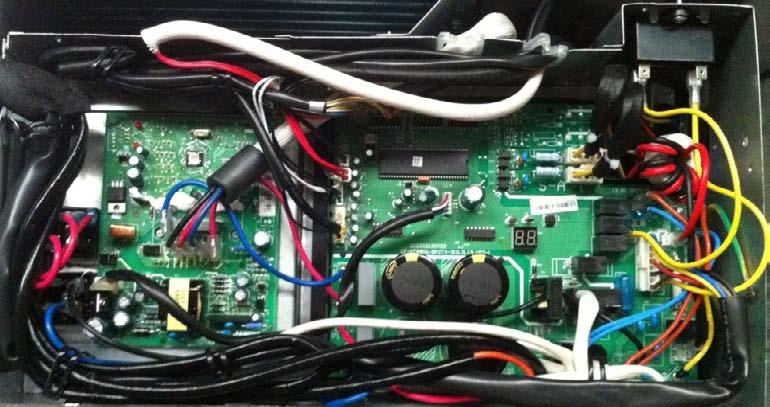
21 PCB board of YN018GMFI16M2D and YN027GMFI16M3D
22 IPM board of YN018GMFI16M2D and YN027GMFI16M3D
23 8.3 Wiring diagram of QUAD (4) Circuit Outdoor Units YN036GMFI16M4D
24 PCB board of YN036GMFI16M4D
25 IPM board of YN036GMFI16M4D
26 8. Troubleshooting 9.1Safety Because there are capacitors on the PCBs and relative circuitry in outdoor units, even after shutting down the power supply, electrical power remain charged in those capacitors. Do not forget to discharge the electrical power remaining in the capacitors before servicing. The value of resistance used for discharging the power should be about 1500 ohms to 2000 ohms. Electrolytic Capacitors (HIGH VOLTAGE! CAUTION!) Bulb (25-40W) The voltage in P3 and P4 in outdoor PCB is high voltage, about 310V The voltage in P5 and P6 in outdoor PCB is high voltage, about 310V
27 8.2 Indoor Unit Error Display WB series Wall Mount Indoor Units: Display Failure ODU Error code E0 Indoor EEPROM malfunction E1 Indoor/ outdoor units communication error E2 Zero-crossing signal error E3 Indoor fan speed has been out of control E5 Open circuit or short circuit of outdoor temperature sensor or outdoor EEPROM malfunction E0,E4 E6 Open circuit or short circuit of T1 or T2 temperature sensor P0 IPM module protection or IGBT over-strong current protection P4 P1 Voltage protection E5 P2 Temperature protection of compressor top P0 P3 Outdoor temperature is lower than -15 C (optional function) P4 Inverter compressor drive protection P7 P5 Mode conflict FB Series Floor Console Indoor Units Operation Timer De-frost Failure X X Open or short circuit of T1 temperature sensor X X Open or short circuit of T2 temperature sensor X X Indoor / outdoor units communication error X Indoor EEPROM malfunction X Outdoor fan speed has been out of control X IPM module protection Open or short circuit of T3 or T4 temperature sensor or Outdoor unit EEPROM parameter error X Temperature protection of compressor top X Inverter compressor drive protection X Mode conflict Indoor fan speed has been out of control flash at 5/sec light ON, X extinguished, flash at 0.5/sec
28 For CB Series Ceiling Cassette, RB Series Ceiling Concealed (Ducted) and UB Series Floor- Ceiling (Flex Mount) Indoor Units: Operation Timer De-frost Alarm Failure Display ODU Error code X X X Open or short circuit of T1 temperature sensor E0 X X X Open or short circuit of T2 temperature sensor E1 X X X Indoor / outdoor units communication error E2 X X X Full-water malfunction E3 X X Indoor EEPROM malfunction E4 X X IPM module protection E5 P4 X X Open or short circuit of T3 or T4 temperature sensor or outdoor EEPROM malfunction X Outdoor fan has been out of control E7 X Indoor fan speed has been out of control F5 X Voltage protection P0 E5 X X Temperature protection of compressor top. P1 P0 X Outdoor unit over-current protection P2 P3 X X Inverter compressor drive protection P4 P7 X Mode conflict P5 flash at 2.5/sec, light ON, X extinguished,, flash at 0.5/sec Note: Digital display is only available for duct type. E6 E0,E4

29 9.3 Outdoor Unit Display Outdoor unit error code function There is a system check switch on the outdoor PCB. Push the switch SW1 to check the states of unit when the unit is running. The digital display will display the follow procedure when push SW1 each time. SW1 Display Remark 1 Indoor unit capacity demand code 2 Outdoor unit running mode code Off:0, Cooling:1, Heating:2 3 Amendatory capacity demand code 4 Outdoor unit fan motor state Off:0, Low speed:1, High speed:2 5 Evaporator outlet temp. for 1# indoor unit Actual data,(if the temp. is lower than -9 degree, the digital display tube 6 Evaporator outlet temp. for 2# indoor unit will show -9.If the temp. is higher than 70 degree, the digital display tube will show 70. If the indoor unit is not connected, the digital display 7 Evaporator outlet temp. for 3# indoor unit tube will show: ) 8 Evaporator outlet temp. for 4# indoor unit 9 Condenser pipe temp. (T3) 10 Outdoor ambient temp.(t4) 11 Compressor discharge temp.(tp) Actual data (If the temp. is lower than 0 degree, the digital display tube will show 0.If the temp. is higher than 99 degree, the digital display tube will show single digit and tens digit. (For example, the digital display tube show 0.5,it means the compressor discharge temp. is 105 degree. If the indoor unit is not connected, the digital display tube will show: ) 12 AD value of current AD data(decimal numeral) 13 EXV open angle for A indoor unit Actual data times 8 14 EXV open angle for B indoor unit Actual data times 8 15 EXV open angle for C indoor unit Actual data times 8 16 EXV open angle for D indoor unit Actual data times 8 17 AD value of voltage AD data(ad data*472/255=actual data) If AD data is higher than 99V, the digital display tube will show single digit and tens digit.
30 18 Indoor unit number The indoor unit can communicate with outdoor unit well. Display Number of indoor unit 19 The last error or protection code 00 means no malfunction 20 frequency value Actual data 21 A indoor unit room temp.(t 1 A) Actual data 22 A indoor unit evaporator temp.(t 2 A) Actual data 23 B indoor unit room temp.(t 1 B) Actual data 24 B indoor unit evaporator temp.(t 2 B) Actual data 25 C indoor unit room temp.(t 1 C) Actual data 26 C indoor unit evaporator temp.(t 2 C) Actual data 27 D indoor unit room temp.(t 1 D) Actual data 28 D indoor unit evaporator temp.(t 2 D) Actual data 29 Check point over Outdoor unit s digital display digits There is a digital display tube in outdoor PCB. Digital display tube display function In standby, the LED displays - - In compressor operation, the LED display the running frequency, In defrosting mode, The LED displays df or alternative displays between running frequency and df (each displays 2s) In compressor pre-heating, The LED displays - - In protection or malfunction, the LED displays error code or protection code.
31 9.3.3 Outdoor unit error display Display digital tube LED STATUS IDU Error (Wall Mount) IDU Error (Others) E0 Outdoor EEPROM malfunction E5 E6 E1 No A Indoor unit coil outlet temp. sensor or connector of sensor is defective E2 No B Indoor unit coil outlet temp. sensor or connector of sensor is defective E3 No C Indoor unit coil outlet temp. sensor or connector of sensor is defective E6 No D Indoor unit coil outlet temp. sensor or connector of sensor is defective E4 Open or short circuit of outdoor temperature sensor(t4) E5 E6 E5 Voltage protection P1 P0 E7 Communication malfunction between IPM board and outdoor main board P0 Temperature protection of compressor discharge (Temperature protection of compressor top(only for M2OC-18HRDN1-M&M3OC-27HRDN1-M) ) P2 P3(P1) P1 High pressure protection (Only for M4OC-36HRDN1-M) P2 Low pressure protection(only form4oc-36hrdn1-m) P3 Current protection of compressor (P2) P4 IPM module protection P0 E5 P6 High temperature protection of condenser P7 Inverter compressor drive protection P4 P4 PF PFC module protection (Only for YN036GMFI16M4D)
32 9.4 Diagnosis and Solution Indoor unit trouble shooting Indoor EEPROM malfunction diagnosis and solution. Malfunction decision conditions Trouble shooting: PCB main chip does not receive feedback from EEPROM chip Installation mistake PCB faulty Supposed causes EEPROM: a read only memory whose contents can be erased and reprogrammed using a pulsed voltage. For the location of EEPROM chip, please refer to the below photos.
33 Indoor / outdoor unit communication error diagnosis and solution. Malfunction decision conditions Supposed causes Indoor unit does not receive the feedback from outdoor unit during 120 seconds. Wiring mistake Indoor or outdoor PCB faulty Trouble shooting:
34 Indoor / outdoor units communication error Start: Power off, then Power on the A/C by the Breaker. (reconnect the power wire). Is it still displaying the error code? Yes Check wiring on the outdoor and indoor terminal follow the wiring diagram. Is all connecting correctly? No Reconnect the wiring No No Reconnect the wiring Yes Turn on all indoor unit by remote controller. Is all indoor unit display No Measure Vs, is it moving alternately between positive value and negative value? (Vs is the voltage between S and L2). Refer PIC 1 No A: Is all the wiring between terminal and Indoor PCB connect ok? Yes Yes Yes Yes Change the Indoor PCB Turn off the all indoor units. Is IPM power LED or operating LED lamp On? Refer PIC2 No change IPM Yes Power on by remote controller, IIs it still displaying the error code after 3 minutes? Is main board lamp on? Refer PIC 3. No Is the reactor connecting well? No Reconnect the wiring Yes Yes Change Outdoor Main PCB No Is indoor units number correct? Check on the outdoor check point. (2 for dual zone, 3 for tri zone, 4 for qua zone). Refer PIC 4. Trouble is solved No first time No second time A Change outdoor unit PCB assembly(include wiring) totally


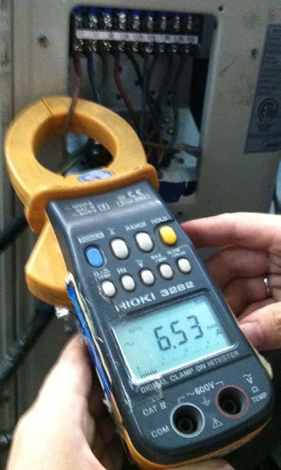
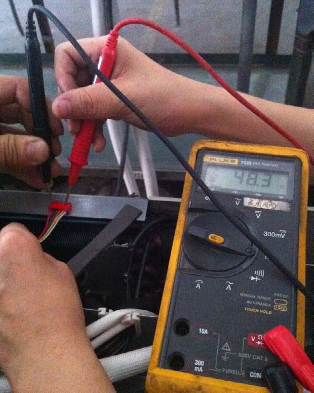
35 Pic 1:Use a multimeter to test the DC voltage between L2 port and S port of outdoor unit. The red pin of multimeter connects with L2 port while the black pin is for S port. When AC is running normally, the voltage will move alternately between positive value and negative value. Pic 2: :IPM (for dual/tri/quad-zone) Power (some modles) Self Check OK Operating

36 PIC3 :Main board LED when power on and unit standby. PIC 4: Check point button, press 18 times for check how many indoor units are connected.
37 zero-crossing signal error diagnosis and solution. Malfunction decision conditions When PCB does not receive zero crossing signal feedback for 4 minutes or the zero crossing signal time interval is abnormal. Supposed causes Connection mistake PCB faulty Trouble shooting:
38 Indoor fan speed has been out of control diagnosis and solution. Malfunction decision conditions When indoor fan speed stays too low (300RPM) for certain time, the unit will stop and the LED will display the failure. Supposed causes Wiring mistake Fan ass y faulty Fan motor faulty PCB faulty Trouble shooting:
39 Index 1: 1.Indoor AC fan motor Measure the resistance value of each winding by using the tester. For the definite value of the resistance, refer to 9.5 Trouble Criterion Of Main Parts 2. Indoor DC fan motor(control chip is inside fan motor) Measure the resistance value of each winding by using the tester. If any resistance value is zero, the fan motor must have problems and need to be replaced. For console: NO. Color 1 Red White 4 Blue 5 Yellow 6 Black
40 For other models: NO. Color 1 Red Black 4 White 5 Yellow 6 Blue Index2: 1: Indoor AC fan motor Power on and set the unit running in fan mode at high fan speed. After running for 15 seconds, measure the voltage of pin1 and pin2. If the value of the voltage is less than 100V(208~240V power supply)or 50V(115V power supply), the PCB must have problems and need to be replaced. 2. Indoor DC fan motor (control chip is inside fan motor) Power on and when the unit is in standby, measure the voltage of pin1-pin3, pin4-pin3 in fan motor connector. If the value of the voltage is not in the range showing in below table, the PCB must have problems and need to be replaced.
41 For other models: For console: DC motor voltage input and output For light commercial (except console): NO. Color Signal Voltage 1 Red Vs/Vm 192V~380V Black GND 0V 4 White Vcc V 5 Yellow Vsp 0~6.5V 6 Blue FG 15V For console: NO. Color Signal Voltage 1 Red VDC 310V White Vcc 15V 4 Blue FG 15V 5 Yellow Vsp 0-7.5V 6 Black GND 0V
42 open or short circuit of temperature sensor diagnosis and solution. Malfunction decision conditions If the sampling voltage is lower than 0.06V or higher than 4.94V, the LED will display the failure. Supposed causes Wiring mistake Sensor faulty PCB faulty Trouble shooting: Check the connections between temperature sensor and PCB. Are the connections good? No Correct the connections. Yes Check the resistance value of the sensor via Appendix 1 and Appendix 2 Is it normal? Yes Replace indoor or outdoor PCB. No Replace the sensor
43 IPM module or IGBT over-strong current protection diagnosis and solution. Malfunction decision conditions Supposed causes Trouble shooting: When the voltage signal that IPM send to compressor drive chip is abnormal, the display LED will show P6 and AC will turn off. Wiring mistake IPM malfunction Outdoor fan ass y faulty Compressor malfunction Outdoor PCB faulty
44 IPM module protection Check whether the voltage range of P N on IPM module is normal? DC V for 18 27KBtu/h; DC V for 36KBtu/h No Check whether the input power supply is correct? V, 1N, 60Hz No Regulate it to correct, then check whether the system can work normally? Yes Yes No Check whether the connecting line between main board and the IPM module is connected tightly No Connect it tightly, check ok or not? Check whether the power supply line is connected correctly and tightly No Connect it correctly and tightly, check ok or not? Yes No Yes No Check whether the connecting line of the compressor is connected correctly or tightly No Connect it well, check ok or not? Check whether the lines in E part box are connected tightly No Connect it tightly, check ok or not? Yes No Replace the IPM module, check whether the system can work normally? No Check if the outdoor fan runs properly or the outdoor unit ventilation is good. No Replace the main board; check whether the system can work normally? Yes For AC fan models, please refer to 9.4 Trouble Criterion Of Main Parts, check whether the resistance of the fan motor is normal. If not, replace the fan motor. For DC fan models, refer to the solution of fan speed has been out of control malfunction. Find out the cause and have it solved. Yes Yes Yes No Check whether the bridge rectifiers are normal? Use the multimeter to measure the resistance between each two terminals, check whether there is the condition that value of resistance is 0 Yes Check whether the connecting line of every reactor is normal? If the line is broken, the resistance of the two ports is (models except for M4OC 36HRFN1 M& M4OC 36HRDN1 M);Check whether the PFC module broken (for M4OC 36HRFN1 M& M4OC 36HRDN1 M) No Replace the bridge rectifiers No No Replace the connecting line or reactor or replace the PFC module(for M4OC 36HRFN1 M) Yes Replace the compressor, check whether the system can work normally? Yes Trouble is solved
45 Over voltage or too low voltage protection diagnosis and solution.
46 Temperature protection of compressor top diagnosis and solution. Malfunction decision conditions Supposed causes If the sampling voltage is not 5V, the LED will display the failure. Wiring mistake Over load protector faulty System block Outdoor PCB faulty Inverter compressor drive error diagnosis and solution The trouble shooting is same with one of IPM module protection(p0).
47 Full-water malfunction diagnosis and solution (For Cassette / Concealed duct) Malfunction decision conditions Supposed causes If the sampling voltage is not 5V, the LED will display the failure. Wiring mistake Water-level switch faulty Water pump faulty Indoor PCB faulty
48 Mode conflict. Error Code Malfunction decision conditions Unit action P5 The indoor units cannot work cooling mode and heating at same time. Heating mode has a priority. When Indoor unit A is working in cooling mode or fan mode, and indoor unit B is set to heating mode, then A will change to off and B will work in heating mode. When Indoor unit A is working in heating mode, and indoor unit B is set to cooling mode or fan mode, then B will change to stand by and A will be no change. Cooling mode Heating Mode Fan Off Cooling mode No Yes No No Heating Mode Yes No Yes No Fan No Yes No No Off No No No No No: No mode conflict; Yes: Mode conflict
49 9.4.2 Outdoor unit trouble shooting E0 (Outdoor EEPROM malfunction) error diagnosis and solution Error Code Malfunction decision conditions Supposed causes Trouble shooting: E0 PCB main chip does not receive feedback from EEPROM chip Installation mistake PCB faulty Outdoor EEPROM malfunction Yes If the EEPROM chip is welded on PCB, replace the PCB directly. Otherwise, check whether the EEPROM chip plugged in PCB well? No Insert the EEPROM well Yes Replace the outdoor main board EEPROM: a read-only memory whose contents can be erased and reprogrammed using a pulsed voltage. For the location of EEPROM chip, please refer to the below photos. Outdoor PCB (YN018GMFI16M2D)

50 E4(open or short circuit of outdoor temperature sensor) diagnosis and solution E1/E2/E3/E6 (open or short circuit of indoor coil temperature sensor) diagnosis and solution. Error Code E1/E2/E3/E4/E6 Malfunction decision conditions Supposed causes If the sampling voltage is lower than 0.06V or higher than 4.94V, the LED will display the failure. Wiring mistake Sensor faulty PCB faulty Trouble shooting:
51 E5 (Voltage protection) error diagnosis and solution. Error Code Malfunction decision conditions Supposed causes Trouble shooting: E5 An abnormal voltage rise or drop is detected by checking the specified voltage detection circuit. Power supply problems. System leakage or block PCB faulty Voltage protection Check the voltage of outdoor unit power supply, whether the voltage between L(L1) and N (L2) is about 187~253VAC No Check the power supply Yes Check whether the voltage of IPM board P and N is normal? DC V for 18-27KBtu/h; DC V for 36KBtu/h No Replace bridge rectifiers, and then check whether the system can run normally No Yes Yes Replace IPM board, and then check whether the system can run normally Yes No Replace outdoor main board Trouble is solved


52 IPM (for dual/trio-zone) bridge rectifier IPM (for quaszone) P-N

53 Remark: Measure the DC voltage between + and - port. The normal value should be 190V~250V.
54 E7 (Communication malfunction between IPM board and outdoor main board) error diagnosis and. Error Code E7 Malfunction decision conditions Supposed causes Trouble shooting: PCB main chip does not receive feedback from IPM module during 60 seconds. Wiring mistake PCB faulty


55 Remark: Use a multimeter to test the DC voltage between black pin and white pin of signal wire The normal value should be around 5V. Use a multimeter to test the DC voltage between black pin and red pin of signal wire. The normal value should be around 12V.
56 P0 (Temperature protection of compressor discharge) error diagnosis and solution. Error Code Malfunction decision conditions Supposed causes Trouble shooting: P0 When the compressor discharge temperature(tp) is more than 115 for 10 seconds, the compressor will stop and reset when Tp is less than 90. Refrigerant leakage Wiring mistake The discharge temperature sensor faulty Outdoor PCB faulty
57 P0 (Temperature protection of compressor top) error diagnosis and solution. (Only for YN018GMFI16M2D and YN027GMFI16M3D) Error Code Malfunction decision conditions Supposed causes Trouble shooting: P0 If the sampling voltage is not 5V, the LED will display the failure. Wiring mistake Over load protector faulty System block Outdoor PCB faulty


58
59 P1 (High pressure protection) error diagnosis and solution. (Only for YN036GMFI16M4D) Error Code Malfunction decision conditions Supposed causes Trouble shooting: P1 If the sampling voltage is not 5V, the LED will display the failure. Wiring mistake Over load protector faulty System block Outdoor PCB faulty


60
61 P2 (Low pressure protection) error diagnosis and solution. (Only for YN036GMFI16M4D) Error Code Malfunction decision conditions Supposed causes Trouble shooting: P2 If the sampling voltage is not 5V, the LED will display the failure. Wiring mistake Over load protector faulty System block Outdoor PCB faulty

62
63 P3 (Current protection of compressor) error diagnosis and solution. Error Code Malfunction decision conditions Supposed causes Trouble shooting: P3 If the compressor current exceeds the current limit value for 10 seconds, the LED will display the failure. Wiring mistake Over load protector faulty System block Outdoor PCB faulty

64
65 P4 (IPM module protection) error diagnosis and solution. Error Code Malfunction decision conditions Supposed causes Trouble shooting: P4 When the voltage signal that IPM send to compressor drive chip is abnormal, the display LED will show P4 and AC will turn off. Wiring mistake IPM malfunction Outdoor fan ass y faulty Compressor malfunction Outdoor PCB faulty
66
67 P6 (High temperature protection of condenser) error diagnosis and solution. Error Code Malfunction decision conditions Supposed causes Trouble shooting: P6 When outdoor pipe temperature is more than 65 C, the unit will stop, and unit runs again when outdoor pipe temperature is less than 52 C The condenser temperature sensor faulty Heat exchanger dirty System block
68 P7 (Inverter compressor drive protection) error diagnosis and solution. The same as P4 (IPM module protection) PF(PFC module protection) error diagnosis and solution. (Only for YN036GMFI16M4D) Error Code PF Malfunction decision conditions Supposed causes When the voltage signal that PFC sends to main control board is abnormal, the display LED will show PF and AC will turn off. Wiring mistake Outdoor PCB faulty Inductance of PFC module faulty PFC module malfunction Trouble shooting:


69 Inductance Two ports of the inductance

70
71 The cooling operation or heating operation does not operate. Supposed causes 4-way valve faulty Check of 4-way, please refer to part 5 in 9.5 Trouble Criterion Of Main Parts When cooling, heat exchanger of non-operating indoor unit freezes. When heating, non-operating indoor unit get warm. Supposed causes EXV faulty Wire and tubing connected in reverse. Check of EXV, please refer to part 6 in 9.5 Trouble Criterion Of Main Parts.
72 9.5 Trouble Criterion Of Main Parts. Spec. Indoor unit Model 9k Wall 12k Wall 18k Wall Indoor fan motor RPG20B RPG20B RPG28H Model 12K Ducted 18K Ducted Indoor fan motor YSK27-4G YSK68-4B Model 12K Cassette 18K Cassette Indoor fan motor WZDK37-38G WZDK37-38G Model 12K Floor-Ceiling 18K Floor-Ceiling Indoor fan motor WZDK55-38GS-W WZDK55-38GS-W Model Indoor fan motor 12K Floor Console RD A Outdoor unit Model Compressor Outdoor fan motor YN018GMFI16M2D YN027GMFI16M3D YN036GMFI16M4D DA130S1C-20FZ DA150S1C-20FZ TNB306FPGMC-L YDK70-6FB YDK53-6FB(B) YDK180-8GB 1.Temperature sensor checking Disconnect the temperature sensor from PCB, measure the resistance value with a tester. Temperature Sensors. Room temp.(t1) sensor, Indoor coil temp.(t2) sensor, Outdoor coil temp.(t3) sensor, Outdoor ambient temp.(t4) sensor, Compressor discharge temp.(tp) sensor. Measure the resistance value of each winding by using the multi-meter.
73 Appendix 1 Temperature Sensor Resistance Value Table ( --K) K Ohm K Ohm K Ohm K Ohm
74 Appendix 2 Unit: ---K Discharge temp. sensor table B(25/50)=3950K R(90 )=5KΩ±3%
 0.")
75 Appendix 3: Compressor check Measure the resistance value of each winding by using the tester. Position Resistance Value DA130S1C-20FZ DA150S1C-20FZ DA250S2C-30MT TNB306FPGMC-L Blue - Red 0.95Ω(20 ) 0.95Ω(20 ) 0.55Ω(20 ) 0.53Ω(20 )
76 3.IPM continuity check Turn off the power, let the large capacity electrolytic capacitors discharge completely, and dismount the IPM. Use a digital tester to measure the resistance between P and UVWN; UVW and N. (+)Red P Digital tester (-)Black N U V W Normal resistance value (Several MΩ) (+)Red U V W (+)Red Digital tester (-)Black N Normal resistance value (Several MΩ) 4. AC Fan Motor. Measure the resistance value of each winding by using the tester. Position Resistance Value RPG20B RPG28H Black - Red 381Ω±8% (20 ) 342Ω±8% (20 ) 183.6Ω±8% (20 ) 180Ω±8% (20 ) (Brand: Weiling) (Brand: Dayang) (Brand: Weiling) (Brand: Wolong) White - Black 267Ω±8% (20 ) 253Ω±8% (20 ) 206Ω±8% (20 ) 190Ω±8% (20 ) (Brand: Weiling) (Brand: Dayang) (Brand: Weiling) (Brand: Wolong) Measure the resistance value of each winding by using the tester.
 317Ω±8% (20 ) 145Ω±8% (20 ) 345Ω±8% (20 ) 627Ω±8% (20 ) 88.")
 138Ω±8% (20 ) Yellow - Blue 76Ω±8% (20 ) 19Ω±8% (20 ) 252Ω±8% (20 ) 88Ω±8% (20 ) 150Ω±8% (20 ) 374.")

77 Position Resistance Value YDK70-6FB YDK180-8GB YSK27-4G YSK68-4B YDK45-6B YSK25-6L YDK53-6FB(B) Black - Red 56Ω±8% (20 ) 24.5Ω±8% (20 ) 317Ω±8% (20 ) 145Ω±8% (20 ) 345Ω±8% (20 ) 627Ω±8% (20 ) 88.5Ω±8% (20 ) Red - Yellow 76Ω±8% (20 ) 19Ω±8% (20 ) 252Ω±8% (20 ) 88Ω±8% (20 ) 150Ω±8% (20 ) 374.3Ω±8% (20 ) 138Ω±8% (20 ) Yellow - Blue 76Ω±8% (20 ) 19Ω±8% (20 ) 252Ω±8% (20 ) 88Ω±8% (20 ) 150Ω±8% (20 ) 374.3Ω±8% (20 ) 138Ω±8% (20 ) 5.4-way valve 1. Power on, use a digital tester to measure the voltage, when the unit operates in cooling, it is 0V. When the unit operates in heating, it is about 230VAC. If the value of the voltage is not in the range, the PCB must have problems and need to be replaced. 2 Turn off the power, use a digital tester to measure the resistance. The value should be 1.8~2.5 KΩ.


78 6.EXV check Disconnect the connectors Red Brown Blue Orange Yellow White Resistance to EXV coil Color of lead wire Normal Value Red- Blue Red - Yellow Brown-Orange About 50Ω Brown-White

79 Red- Blue Red - Yellow


80 Brown-Orange Brown-White
 Stop operation of the air conditioner and turn OFF the power breaker. 2) Remove the screws of top cover, and remove the top cover.")
 5) Remove the screws of big handle, and remove the big handle.")
81 9. Disassembly Instructions Model: YN018GMFI16M2D No. Part name Procedures Remarks How to remove the panel Screws of top cover 1 Panel plate plate. 1) Stop operation of the air conditioner and turn OFF the power breaker. 2) Remove the screws of top cover, and remove the top cover. (9 screws) 3) Remove the screws of right front side panel, and remove the right front side panel (2 screws) 4) Remove the screws of front panel, and remove the front panel. (9 screws) 5) Remove the screws of big handle, and remove the big handle.(4 screws) 6) Remove two screws of terminal board, two screws of water collector and twelve screws of right-rear panel, and remove the right-rear panel. Screws of front panel Screws of rightrear panel Screws of right front side panel Screws of top cover Screws of front panel


82 Screws of big handle Screws of rightrear panel Screws of water collector Screws of terminal board
83 How to remove the fan ass y. 2 Fan ass y 1) Remove the top cover, right front side panel and front panel from item 1.step 1~4 2 2) Remove the hex nut fixing the fan. 3) Remove the fan. 4 4) Remove the two fixing screws and then open the electrical control box cover. 5) Disconnect the fan motor connector CN3(5p,white) from the PCB board. 5 6) Remove the fan motor after unfastening six fixing screws. Note: There are two kinds of screws. Please pay attention to it when install the fan motor.
 Disconnect following connection wires and connectors between IPM and IPM board PCB board PCB.")
, connected to compressor. CN1: (5p, white),connected to CN22 on PCB.")
 Disconnect the connectors Screws of IPM and wires connected from CN21 CN26/CN28 PCB and other parts.")
84 How to remove the electrical 3 Electrical parts parts. 1) Perform work of item 1,2. 2) Disconnect following connection wires and connectors between IPM and IPM board PCB board PCB. CN1 N UVW to compressor P P: (+, red), connected to P2 on PCB. N: (-, blue), connected to P4 on PCB. UVW: (blue-red-black), connected to compressor. CN1: (5p, white),connected to CN22 on PCB. 3) Remove the IPM board after removing the two screws. 4) Disconnect the connectors Screws of IPM and wires connected from CN21 CN26/CN28 PCB and other parts. Connectors: CN14 CN22 CN29/ CN13:T-A,B temp. sensor (2p/2p,white) CN18:T3/T4 temp. sensor (2p/2p,white) CN14: Top temp. sensor (2p, white) CN21: Tdischarge temp. sensor (2p,white) CN3 CN26/CN28: Electronic expansive
 CN7/CN10: Crankcase heating cable (red-red) CN10 CN7 CN9")
 5) Disconnect the grounding wires (yellow-green). 6) Remove the PCB board.")
85 valve A,B (6p/6p,red/red) CN29/CN31: S-A,S-B (3p/3p,white/white) Wires: CN6/CN9: 4-way valve (blue-blue) CN7/CN10: Crankcase heating cable (red-red) CN10 CN7 CN9 CN6 CN11/CN12: Fan capacitor(yellow- yellow) CN1:L-IN (red) CN12 CN11 CN2:N-IN (black) 5) Disconnect the grounding wires (yellow-green). 6) Remove the PCB board. CN1 5 CN2
 Remove the electrical control box and partition plate. 3) Extract refrigerant gas.")
 Remove terminal cover of compressor, and disconnect wires of compressor thermo and compressor from the terminal.")
 Remove the hex nuts and washers fixing the compressor to bottom plate. 8) Lift the compressor.")
86 How to remove the 4 Compressor compressor. 1) Perform work of item 1,2,3. 2) Remove the electrical control box and partition plate. 3) Extract refrigerant gas. 4) Remove the sound insulation material and 6 crankcase heating cable. 5) Remove terminal cover of compressor, and disconnect wires of compressor thermo and compressor from the terminal. 6) Remove the discharge pipe 7 and suction pipe with a burner. 7) Remove the hex nuts and washers fixing the compressor to bottom plate. 8) Lift the compressor. 5 Reactor1 2 How to remove the reactor 1) Perform work of item 1 2) Remove two screws of cover of inductance, and remove the cover of inductance 3) Disconnect two pieces of connection wirings Screws of cover of inductance between reactor and capacitor and connection
 Connection wirings of reactor2 (red, red) 4) Remove")
 Perform work of item 1 2) Disconnect two pieces of")
87 wirings between reactor and rectifier. Connection wirings of reactor1 (blue, orange) Connection wirings of reactor2 (red, red) 4) Remove two screws of each reactor, and remove the reactor. 6 Reactor3 How to remove the reactor 1) Perform work of item 1 2) Disconnect two pieces of connection wirings. 3) Remove two screws of each reactor, and remove the reactor. Screws of reactor Connection wirings
 Remove the electrical parts from item 3. 4) Remove fixing screw of the coil, and remove the coil.")
88 Screws of reactor 7 The 4-way valve How to remove the 4-way valve 1) Perform work of item 1,2. 2) Extract refrigerant gas. 3) Remove the electrical parts from item 3. 4) Remove fixing screw of the coil, and remove the coil. 5) Detach the welded parts of 4-way valve and pipe. Coil Welded parts
 Remove the electrical parts from item 3.. 3) Remove the coils.")
89 8 The expansion valve How to remove the expansion valve 1) Perform work of item 1,2. 2) Remove the electrical parts from item 3.. 3) Remove the coils. 4) Detach the welded parts of expansion valves and pipes. Expansion valves Coils
 Remove the screws of top cover, and remove the top cover.")
 5) Remove the screws of big handle, and remove the big handle.")
90 Model: YN027GMFI16M3D No. Part name Procedures Remarks 1 Panel plate How to remove the panel plate. 1) Stop operation of the air conditioner and turn OFF the power breaker. 2) Remove the screws of top cover, and remove the top cover. (9 screws) 3) Remove the screws of right front side panel, and remove the right front side panel (2 screws) 4) Remove the screws of front panel, and remove the front panel. (9 screws) 5) Remove the screws of big handle, and remove the big handle.(4 screws) Screws of top cover Screws of front panel Screws of right front side panel Screws of top cover 6) Remove two screws of terminal board, two screws of water collector and twelve screws of right-rear panel, and remove the right-rear panel. Screws of rightrear panel Screws of front panel

 Remove the top cover, right")
 Remove the hex nut fixing the fan.")
91 Screws of big handle Screws of right-rear panel Screws of water collector Screws of terminal board How to remove the fan ass y. 2 Fan ass y 1) Remove the top cover, right front side panel and front panel from item 1.step 1~4 2 2) Remove the hex nut fixing the fan. 3) Remove the fan.
 Remove the fan motor after unfastening six fixing screws. Note: There are two kinds of screws. Please pay attention to it when install the fan motor.")
92 4 4) Remove the two fixing screws and then open the electrical control box cover. 5) Disconnect the fan motor connector CN3(5p,white) from the PCB board. 5 6) Remove the fan motor after unfastening six fixing screws. Note: There are two kinds of screws. Please pay attention to it when install the fan motor. How to remove the electrical 3 Electrical parts parts. 1) Perform work of item 1,2. 2) Disconnect following connection wires and connectors between IPM and PCB. P: (+, red), connected to P2 on PCB. IPM board PCB board
,connected to CN22 on PCB. 3) Remove the IPM board after removing the two screws.")
 CN3 CN18:T3/T4 temp.")
 CN28/CN26/CN25: Electronic expansive valve A,B,C (6p/6p/6p,red/red/red) CN31/CN29/CN27:")
93 N: (-, blue), connected to P4 on PCB. CN1 N UVW to compressor P UVW: (blue-red-black), connected to compressor. CN1: (5p, white),connected to CN22 on PCB. 3) Remove the IPM board after removing the two screws. Screws of IPM CN21 CN18 CN13 CN25/CN26/CN28 CN22 CN27/CN29/CN31 4) Disconnect the connectors and wires connected from PCB and other parts. CN10 CN9 Connectors: CN13:T-A,B,C temp. sensor (2p/2p/2p,white) CN3 CN18:T3/T4 temp. sensor (2p/2p,white) CN21: Tdischarge temp. sensor (2p,white) CN28/CN26/CN25: Electronic expansive valve A,B,C (6p/6p/6p,red/red/red) CN31/CN29/CN27: S-A,S-B,S-C (3p/3p/3p,white/white/white) CN7 CN1 CN6 CN12 CN11 5 CN2 Wires: CN6/CN9: 4-way valve (blue-blue)
 Perform work of item 1,2,3. 2) Remove the electrical control box and partition plate. 3) Extract refrigerant gas.")
94 CN7/CN10: Crankcase heating cable (red-red) CN11/CN12: Fan capacitor(yellow- yellow) CN1:L-IN (red) CN2:N-IN (black) 5) Disconnect the grounding wires (yellow-green). 6) Remove the PCB board. How to remove the 4 Compressor compressor. 1) Perform work of item 1,2,3. 2) Remove the electrical control box and partition plate. 3) Extract refrigerant gas. 4) Remove the sound insulation material and crankcase heating cable. 5) Remove terminal cover of compressor, and disconnect wires of compressor thermo and compressor from the terminal. 6) Remove the discharge pipe and suction pipe with a burner. 7) Remove the hex nuts and washers fixing the compressor to bottom plate. 8) Lift the compressor. 6 7
 Disconnect two pieces of connection wirings between")
 Connection wirings of reactor2 (red, red) 4) Remove two screws of each")
95 5 Reactor1 2 How to remove the reactor 1) Perform work of item 1 2) Remove two screws of cover of inductance, and remove the cover of inductance Screws of cover of inductance 3) Disconnect two pieces of connection wirings between reactor and capacitor and connection wirings between reactor and rectifier. Connection wirings of reactor1 (blue, orange) Connection wirings of reactor2 (red, red) 4) Remove two screws of each reactor, and remove the reactor. Screws of reactor
 Remove two screws of each reactor, and remove the reactor.")
 Remove the electrical parts from item 3. 4) Remove fixing screw of the coil, and remove the coil.")
96 6 Reactor3 How to remove the reactor 1) Perform work of item 1 2) Disconnect two pieces of connection wirings. Connection wirings 3) Remove two screws of each reactor, and remove the reactor. Screws of reactor 6 The 4-way valve How to remove the 4-way valve 1) Perform work of item 1,2. 2) Extract refrigerant gas. 3) Remove the electrical parts from item 3. 4) Remove fixing screw of the coil, and remove the coil. 5) Detach the welded parts of 4-way valve and pipe. Coil Welded parts
 Remove the electrical parts from item 3. 3) Remove the coils.")
97 7 The expansion valve How to remove the expansion valve 1) Perform work of item 1,2. 2) Remove the electrical parts from item 3. 3) Remove the coils. 4) Detach the welded parts of expansion valves and pipes. Expansion valves. Coils
 Stop operation of the air conditioner and turn OFF the power breaker.")

 Screws of front panel 4) Remove the screws of front panel,")
98 Model: YN036GMFI16M4D No. Part name Procedures Remarks 1 Panel plate How to remove the panel plate. Screws of top cover 1) Stop operation of the air conditioner and turn OFF the power breaker. Screws of front panel Screws of right front side panel Screws of top cover 2) Remove the screws of top cover, and remove the top cover. (8 screws) 3) Remove the screws of right front side panel, and Screws of rightrear panel remove the right front side panel (2 screws) Screws of front panel 4) Remove the screws of front panel, and remove the front panel. (10 screws) 5) Remove the screws of big
 6) Remove two screws of terminal")


99 handle, and remove the big handle.(4 screws) 6) Remove two screws of terminal board, two screws of water collector and thirteen screws of right-rear Screws of big handle panel, and remove the right-rear panel. Screws of rightrear panel Screws of water collector Screws of terminal board
 Remove the electrical control box cover after remove 5 screws. 5) Disconnect the fan motor connector CN3(5p,white) on the PCB board.")
 Disconnect the following connection wires and connectors on the IPM. P: (+, red), connected to P2 on PCB. PFC board PCB board N: (-, blue), connected to P4 on PCB.")
100 How to remove the fan ass y. 2 Fan ass y 1) Remove the top cover, right front side panel and front panel from item 1.step 1~4. 2 2) Remove the hex nut fixing the fan. 3) Remove the fan. 4) Remove the electrical control box cover after remove 5 screws. 5) Disconnect the fan motor connector CN3(5p,white) on the PCB board. 5 6) Remove the fan motor after unfastening three fixing 6 screws. How to remove the electrical IPM board 3 Electrical parts parts. 1) Perform work of item 1, 2. 2) Disconnect the following connection wires and connectors on the IPM. P: (+, red), connected to P2 on PCB. PFC board PCB board N: (-, blue), connected to P4 on PCB. UVW: (blue-red-black), connected to compressor. CN1: (5p, white),connected to CN22 on PCB. CN202:(2p, white),connected to CN8 on PFC.


, connected to rectifier.")
, connected to CN33 on PCB.")
101 UVW to compressor 3) Remove the IPM board after removing the two screws. P N CN202 CN1 Screws of IPM board 4) Disconnect following connection wires and connectors on the PFC. IPM Board C and CN12: (yellow-yellow), connected to PFC inductance. R and CN12: (blue-red), connected to rectifier. + and - : (red-blue), connected to P1 and P3 on PCB. CN7: (4p,red), connected to CN33 on PCB. CN12 5 CN7 CN8 CN8: (2p,white), connected to CN202 on IPM. 5) Remove the PFC board after remove the two R - C + screws. 6) Disconnect four wires (red-
 Disconnect following connection wires and connectors between PCB and other components.")
, connected to on PFC. RY1: (red), connected to rectifier.")
, connected to CN7 on PFC.")
, connected to 4 way valve.")
102 blue from PFC and blackred from PCB), then the rectifier can be removed. PFC Board 7) Disconnect following connection wires and connectors between PCB and other components. P4: (blue), connected to N on IPM. P2: (red), connected to P on IPM. P1: (red), connected to + on PFC. 6 P3: (blue), connected to on PFC. RY1: (red), connected to rectifier. CN32: (black), connected to rectifier. CN22: (5p, white), connected to CN1 on IPM. CN33: (4p, red), connected to CN7 on PFC. P4 P2 P1 P3 CN11/CN12: (yellow/yellow), connected to fan capacity. RY1 CN32 CN24/CN27/CN29/CN31 CN10 CN1 CN6 CN6/CN9: (blue/blue), connected to 4 way valve. CN7/CN10: (black/red), connected to crankcase heating cable. CN13: T2B-A,B,C,D temp. sensor (2p/2p/2p/2p, white) CN21: Tdischarge temp. sensor (2p, white) CN9 CN11 CN12 CN3 CN7 CN2 CN18: T3/T4/T3/T4 temp. sensor
 CN28/CN26/CN25/CN23: electronic expansive valve")
 CN22 CN33")
, grounding wires of PCB.")

103 (2p/2p, white) CN15: High and low pressure switch (2p/2p, white) CN28/CN26/CN25/CN23: electronic expansive valve A,B,C,D (6p/6p/6p/6p,red/red/red/red) CN31/CN29/CN27/CN24: S-A,B,C,D (3p/3p/3p/3p,white/white/white/white) CN22 CN33 CN1-CN2: (red-black), connected to power terminal P-1: (yellow-green), grounding wires of PCB. 8) Remove the PCB board after remove the fixing screws. CN15 CN21 CN18 CN13 CN28/CN26/CN25/CN23 P-1 How to remove the 4 Compressor compressor.
 Remove terminal cover of compressor, and disconnect wires of compressor thermo and compressor from the terminal. 6) Remove the discharge pipe and suction pipe with a burner.")
 Extract refrigerant gas. 3) Remove the electrical parts from item 3. 4) Remove fixing screw of the coil, and remove the coil. 5) Detach the welded parts of 4-way valve and pipe.")
104 1) Perform work of item 1,2,3 2) Remove the electrical control box and partition plate. 3) Extract refrigerant gas. 4) Remove the sound insulation material and crankcase heating cable. 5) Remove terminal cover of compressor, and disconnect wires of compressor thermo and compressor from the terminal. 6) Remove the discharge pipe and suction pipe with a burner. 7) Remove the hex nuts and washers fixing the compressor to bottom plate. 8) Lift the compressor The 4-way valve How to remove the 4-way valve 1) Perform work of item 1,2. 2) Extract refrigerant gas. 3) Remove the electrical parts from item 3. 4) Remove fixing screw of the coil, and remove the coil. 5) Detach the welded parts of 4-way valve and pipe. Coil Welded parts
 Remove the coils. 4) Detach the welded parts of expansion valves and pipes. Expansion valves Coils 10.")
105 6 The expansion valve How to remove the expansion valve 1) Perform work of item 1,2. 2) Remove the electrical parts from item 3.. 3) Remove the coils. 4) Detach the welded parts of expansion valves and pipes. Expansion valves Coils 10. Exploded Views: Available under a separate document file.
SUPER DC INVERTER MULTI TYPE INSTRUKCJA SERWISOWA
 ODMFI-B-1211 INSTRUKCJA SERWISOWA SUPER DC INVERTER MULTI TYPE K2OD-14HFN1-Q, K2OD-18HFN1-Q, K3OD-21HFN1-Q K3OD-27HFN1-Q, K4OD-28HFN1-Q, K4OA-36HFN1-Q K5OC-36HFN1-Q DC MULTI OUTDOOR UNITS CONTENTS 1. General
SERVICE MANUAL Room Air Conditioner DC Inverter Multi Split Outdoor units
 SERVICE MANUAL Room Air Conditioner DC Inverter Multi Split Outdoor units FS2MIF-140AE2 FS2MIF-180AE2 FS3MIF-210AE2 FS3MIF-270AE2 FS4MIF-280AE2 FS4MIF-360AE2 FS5MIF-360AE2 NOTE: Before servicing the unit,
KMIR218-H221 / KMIR327-H217 / KMIR436-H217 / KMIR545-H219
 Multi outdoor units SERVICE MANUAL Multi - Zone heat pump units Model Numbers: KMIR218-H221 / KMIR327-H217 / KMIR436-H217 / KMIR545-H219 Table of Contents 1. Indoor Unit Combination 2. Suggested Indoor
Multi zone. MULTI OUTDOOR UNITsS. CONDENsSING UNITsS. Revision V1.0: Table of Contents
 MULTI OUTDOOR UNITsS sservice MANUAL Multi zone CONDENsSING UNITsS Revision V1.0: 20160616 Table of Contents 1. Indoor Unit Combination 2. Suggested Indoor Unit Model Numbers 3. Dimension Of Outdoor Unit
Multi zone Two, Three, Four and Five Zones
 MULTI SPLIT SYSTEM OUTDOOR UNITS SERVICE MANUAL Multi zone Two, Three, Four and Five Zones DC INVERTER MULTI ZONE OUTDOOR UNITS Revision A: ODMI E 1601 PDB55/2016 Model Numbers: YN020GMFI22M2D YN030GMFI22M3D
FROZEN SERIE SERVICE MANUAL. DC Inverter R32. Sistemi per la climatizzazione
 DC Inverter R32 Sistemi per la climatizzazione SERVICE MANUAL FROZEN SERIE CONTENTS 1. General information of Outdoor Units... 3 2. Features... 4 3. Dimensions... 5 4. Refrigeration Cycle Diagram... 6
Service Manual AIR CONDITIONER
 Service Manual AIR CONDITIONER DC INVERTER MULTI TYPE This manual applies to models: High Wall Duct Cassette Console Universal CDU 42QHF009DS 42QHF012DS 42QHF018DS 42QSM009DS 42QSM012DS 42QSM018DS 42QTD009DS
MULTI INVERTER SERIE H6M
 MULTI INVERTER SERIE H6M Service manual www.mundoclima.com Thank you very much for purchasing our products. Please read this manual carefully before installing and using the unit. ODMFI-B1-1606 CL20440
KSIM20912-H216 KSIM30912-H216 KSIM40912-H216
 SERVICE MANUAL KLIMAIRE AIRCONDITIONER KSIM DC INVERTER MULTI TYPE KSIM20912-H216 KSIM30912-H216 KSIM40912-H216 DC MULTI OUTDOOR UNITS CONTENTS 1. General information of Outdoor Units...3 2 Features...4
SERVICE MANUAL 42QHF009DS* 42QHF012DS* 42QHF018DS* 42QHF022DS* 38QUS009DS* 38QUS012DS* 38QUS018DS* 38QUS022DS* Indoor unit.
 SERVICE MANUAL Indoor unit Outdoor unit 42QHF009DS* 42QHF012DS* 42QHF018DS* 42QHF022DS* 38QUS009DS* 38QUS012DS* 38QUS018DS* 38QUS022DS* INDEX PART1 GENERAL INFORMATION PART2 ELECTRICAL DIAGRAM PART3 TROUBLE
YC ON-OFF SERIES. Service Manual
 YC ON-OFF SERIES Service Manual CONTENTS 1. Precaution... 3 1.1 Safety Precaution... 3 1.2 Warning... 3 2. Model Lists... 6 3. Dimension... 7 3.1 Indoor Unit... 7 3.2 Outdoor Unit... 11 4. Refrigerant
DuctlessAire ES Series. Service Manual 2016 ABSSA-B4-1601
 DuctlessAire ES Series Service Manual 2016 ABSSA-B4-1601 CONTENTS 1. Precaution... 1 1.1 Safety Precaution... 1 1.2 Warning... 1 2. Model list... 4 3. Dimension... 5 3.1 Indoor Unit... 5 3.2 Outdoor Unit...
TROUBLESHOOTING TROUBLESHOOTING. Indoor unit EEPROM parameter error. Indoor / outdoor units communication error. Zero-crossing signal detection error
 www.olmo-comfort.com TROUBLESHOOTING When below list for identification of error code occurs, please turn off air conditioner and disconnect power, and then contact the qualified professionals for service.
SERVICE MANUAL SPLIT WALL-MOUNTED TYPE MODELS MWCOHC30S/MRCOHC30AS MWCOHC36S/MRCOHC36AS
 SERVICE MANUAL SPLIT WALL-MOUNTED TYPE MODELS MWCOHC30S/MRCOHC30AS MWCOHC36S/MRCOHC36AS CONTENTS 1. Precaution... 1 1.1 Safety Precaution... 1 1.2 Warning... 1 2. Function... 6 3. Dimension... 7 3.1 Indoor
SERVICE MANUAL K LIGHT COMMERCIAL
 SERVICE MANUAL 36 48 60K LIGHT COMMERCIAL Cassette indoor unit Under-ceiling indoor unit Ducted indoor unit 42QTD036DS* 42QTD048DS* 42QTD060DS* 42QZL036DS* 42QZL048DS* 42QZL060DS* 42QSM036DS* 42QSM048DS*
Installation, Operation & Maintenance
 Installation, Operation & Maintenance Contura 5G Series R410a High Ambient & High Efficiency MS-SVX041A-EN 1 Contents 1. Precaution 1.1 Safety Precuation 03 1.2 Warning 03 2. Product Specifications 06
Mission 3D Inverter Series
 Mission 3D Inverter Series Service Manual 2014 MBSEU-A-1412 CONTENTS 1. Precaution... 3 1.1 Safety Precaution... 3 1.2 Warning... 3 2. Function... 6 3. Dimension... 7 3.1 Indoor Unit... 7 3.2 Outdoor Unit...
Dream Inverter Series. Service Manual 2017
 Dream Inverter Series Service Manual 2017 CONTENTS 1. Precaution... 3 1.1 Safety Precaution... 3 1.2 Warning... 3 2. Model List... 6 3. Dimension... 7 3.1 Indoor Unit... 7 3.2 Outdoor Unit... 11 4.Refrigerant
HABITAT USER MANUAL TIN310**V33 TIN414**V33 TIN520**V33 TIN625**V33 TIN1036H2V02 TIN1939H2V02 INVERTER MINI SPLIT
 HABITAT INVERTER MINI SPLIT USER MANUAL TIN310**V33 TIN414**V33 TIN520**V33 TIN625**V33 TIN1036H2V02 TIN1939H2V02 WARNING The information contained in the manual is intended for use by a qualified service
Service Manual for TAS-18EHN, TAS-24EHN
 Service Manual for TAS-18EHN, TAS-24EHN CONTENTS 1. Precaution... 3 1.1 Safety Precaution... 3 1.2 Warning... 3 2. Function... 7 3. Dimension... 8 3.1 Indoor Unit... 8 3.2 Outdoor Unit... 10 4. Refrigerant
NORTH AMERICAN HVAC PRODUCTS LTD 3208 BETA AVE, BURNABY BC V5G 4K4 CSNA-1305-A SERVICE MANUAL AIR CONDITIONER SPLIT WALL-MOUNTED TYPE.
 NORTH AMERICAN HVAC PRODUCTS LTD 3208 BETA AVE, BURNABY BC V5G 4K4 CSNA-1305-A SERVICE MANUAL AIR CONDITIONER SPLIT WALL-MOUNTED TYPE Corona Series CONTENTS 1. Precaution... 1 1.1 Safety Precaution...
SERVICE MANUAL. Room Air Conditioner Split Wall-Mounted Type
 SERVICE MANUAL Room Air Conditioner Split Wall-Mounted Type FSAIF-Pro-95AE2 / FSOAIF-Pro-95AE2 FSAIF-Pro-125AE2 / FSOAIF-Pro-125AE2 FSAIF-Pro-185AE2 / FSOAIF-Pro-185AE2 FSAIF-Pro-245AE2 / FSOAIF-Pro-245AE2
F SERIES ON-OFF SERIES. Service Manual 2016
 F SERIES ON-OFF SERIES Service Manual 2016 CONTENTS 1. Precaution... 3 1.1 Safety Precaution... 3 1.2 Warning... 3 2. Function... 6 3. Dimension... 7 3.1 Indoor Unit... 7 3.2 Outdoor Unit... 9 4. Refrigerant
Bosch Split-Type Ductless Air Conditioner / Heat Pump
 Bosch Split-Type Ductless Air Conditioner / Heat Pump Climate 5000 AA Series Service Manual 2 Bosch Climate 5000 AA Series Split Type Ductless Air Conditioner / Heat Pump Service Manual Data subject to
Blanc ON-OFF Series. Service Manual 2016
 Blanc ON-OFF Series Service Manual 2016 MSMA1A-07HRN1 / MOAB02-07HN1 MSMA1A-09HRN1 / MOAB02-09HN1 MSMA1B-12HRN1 / MOBA01-12HN1 MSMA1C-18HRN1 / MOBA03-18HN1 MSMA1D-24HRN1 / MOCA02-24HN1 1 Blanc On-off DM16-01.01.07en
SERVICE MANUAL. Room Air Conditioner Split Wall-Mounted Type
 SERVICE MANUAL Room Air Conditioner Split Wall-Mounted Type FSAIF-Pro-94AE2 / FSOAIF-Pro-94AE2 FSAIF-Pro-124AE2 / FSOAIF-Pro-124AE2 FSAIF-Pro-184AE2 / FSOAIF-Pro-184AE2 FSAIF-Pro-244AE2 / FSOAIF-Pro-244AE2
Mono DC. VERTU MONO Split DC Inverter Air Conditioner SERVICE MANUAL MSV1-18HRDN1-MQ0W. Revision A: , Content updated.
 VERTU MONO Split DC Inverter Air Conditioner SERVICE MANUAL Mono DC Revision A: 1305080001, Content updated. Model Numbers: 0 MSV1-09HRFN1-MT0W MSV1-12HRDN1-MQ0W MSV1-24HRDN1-MQ0W MSV1-12HRFN1- MT0W MSV1-18HRDN1-MQ0W
Vertu Plus 3D Inverter Series
 Vertu Plus 3D Inverter Series Service Manual 2015 VPSFI -A-1511 CONTENTS 1. Precaution... 3 1.1 Safety Precaution... 3 1.2 Warning... 3 2. Function... 6 3. Dimension... 7 3.1 Indoor Unit... 7 3.2 Outdoor
15C Inverter Series. Service Manual
 15C Inverter Series Service Manual CONTENTS 1. Precaution... 1 1.1 Safety Precaution... 1 1.2 Warning... 1 2. Function... 4 3. Dimension... 5 3.1 Indoor Unit... 5 3.2 Outdoor Unit... 7 4. Wiring Diagram...
KSIN INVERTER SERIES Service Manual 2013
 KSIN INVERTER SERIES Service Manual 2013 CONTENTS 1. Precaution............ 1 1.1 Safety Precaution... 1 1.2 Warning... 1 2. Function............ 6 3. Dimension............ 8 3.1 Indoor Units... 8 3.2
Light Commercial SUPER INVERTER SERIES MULTI TYPE
 Light Commercial SUPER INVERTER SERIES MULTI TYPE Service Manual 2017 CONTENTS 1. General information of Indoor Units... 1 2. Features... 2 3. Dimensions... 12 4. Service Space (unit: mm)... 19 5. Wiring
Westinghouse. Split System Inverter Series. Service Manual
 Westinghouse Split System Inverter Series Service Manual Model: WIWPK/WCHPK Range: 2.6kw 7.6kw CONTENTS 1. Precaution... 1 1.1 Safety Precaution... 1 1.2 Warning... 1 2. Function... 5 3. Dimension... 6
Service Manual CAUTION ! WARNING SAFETY CONSIDERATIONS INTRODUCTION. 38MA*R Outdoor Unit Single Zone Ductless System Sizes 09 to 36
 38MA*R Outdoor Unit Single Zone Ductless System Sizes 09 to 36 Service Manual TABLE OF CONTENTS PAGE SAFETY CONSIDERATIONS... 1 INTRODUCTION... 1 MODEL / SERIAL NUMBER NOMENCLATURES... 2 SPECIFICATIONS...
SEER 15 DC INVERTER SERIES
 NORTH AMERICAN HVAC PRODUCTS LTD Address: 3208 Beta Ave, Burnaby BC Canada V5G 4K4 Tel: 604-4308496 Fax: 1-866-9034371 WWW.NORTHAMERICANHVAC.COM SEER 15 DC INVERTER SERIES Service Manual 2013 SINGLE ZONE
INVERTER SERIE H6 Service manual
 INVERTER SERIE H6 Service manual MUPR-H6 www.mundoclima.com Thank you very much for purchasing our products. Please read this manual carefully before installing and using the unit. AESFI-A-1509 CL20015
Mono 3D. SMART Inverter Air Conditioner SERVICE MANUAL. Revision A: , Content updated.
 z SMART Inverter Air Conditioner SERVICE MANUAL Mono 3D Revision A: 160003001, Content updated. Table of Contents 1. Precaution 2. Part Names And Functions 3. Dimension 4. Refrigerant Cycle Diagram 5.
INSTRUKCJA SERWISOWA 12F INVERTER SERIES. Service Manual FSI-A-1310
 INSTRUKCJA SERWISOWA 12F INVERTER SERIES Service Manual 2013 12FSI-A-1310 CONTENTS 1. Precaution... 3 1.1 Safety Precaution... 3 1.2 Warning... 3 2. Function... 7 3. Dimension... 8 3.1 Indoor Unit... 8
LUNA INVERTER SERIES. Service Manual ASI-A-1301
 LUNA INVERTER SERIES Service Manual 2013 9ASI-A-1301 CONTENTS 1. Precaution... 3 1.1 Safety Precaution... 3 1.2 Warning... 3 2. Function... 7 3. Dimension... 8 3.1 Indoor Unit... 8 3.2 Outdoor Unit...
DCH DCI Series R410A HEATPUMP REFRIGERANT
 DCH DCI Series Indoor Units Outdoor Units JOSI-DCH009-N11 JSP023054 JOAU-DCY009-H11 JSP062910 JOSI-DCH012-N11 JSP023055 JOAU-DCY012-H11 JSP062911 JOSI-DCH018-N11 JSP023056 JOAU-DCY018-H11 JSP062912 JOSI-DCH024-N11
Service Manual. Multi Split Type Heat Pump Air Conditioners. Applied to: HS-9U2IM_HOS-18U2IM HS-9U11IM_HS-12U11IM_HOS-21U11IM
 Service Manual Multi Split Type Heat Pump Air Conditioners Applied to: HS-9U2IM_HOS-18U2IM HS-9U11IM_HS-12U11IM_HOS-21U11IM CONTENT 1. Product features 2. Specification 3. Dimensions 4. Refrigeration cycle
Service manual. MIV V4+ Mini
 DM12-01.01.05en Service manual MIV V4+ Mini DC INVERTER R410A (~220V, 50Hz, 1Ph) MVUH80A-VA1 Contents Part 1 General Information... 1 Part 2 Outdoor Units... 6 Part 3 Installation... 44 DM12-01.01.05en
Corona Plus varmepumper
 Corona Plus varmepumper SERVICEMANUAL MSC-09HRDN1-QD0E MSC-12HRDN1-QC6E CONTENTS 1. Precaution... 1 1.1 Safety Precaution... 1 1.2 Warning... 1 2. Function... 4 3. Dimension... 6 3.1 Indoor Unit... 6 MSC-09HRDN1-QD0(E)
SERVICE MANUAL. KSIO MINI Split DC Inverter Air Conditioner. Model Numbers:
 KSIO MINI Split DC Inverter Air Conditioner SERVICE MANUAL Model Numbers: KSIO009-H124-I KSIO012-H123-I KSIO018-H221-I KSIO024-H219-I KWIO09-H2 KWIO12-H2 Table of Contents 1. Precaution 2. Part Names And
Table of Contents. Page. 1. Safety Precautions Specifications Product Features Maintenance and Disassembly...
 Table of Contents Page 1. Safety Precautions... 1 1. In case of Accidents or Emergency 2. Pre-Installation and Installation 3. Operation and Maintenance 2. Specifications... 3 1. Model Reference 2. Electrical
NORTH AMERICAN HVAC PRODUCTS LTD. Tel: Fax: DC Inverter Single Zone Split Wall-Mounted Type
 NORTH AMERICAN HVAC PRODUCTS LTD Tel: 604-4308496 Fax: 1-866-9034371 www.northamericanhvac.com Service Manual DC Inverter Single Zone Split Wall-Mounted Type Model Refrigerant type Power supply MSV1-18HRDN1-MQ0
PRODIGY 3D Inverter. Technical Manual
 PRODIGY 3D Inverter Technical Manual CONTENTS 1. Precaution... 3 1.1 Safety Precaution... 3 1.2 Warning... 3 2. Function and specifications... 5 3. Dimension... 10 3.1 Indoor Unit... 10 3.2 Outdoor Unit...
Service Manual. Room Air Conditioner Split Wall-Mounted Type. Applies to: HSG-09HRN1 HSG-12HRN1 HSG-18HRN1 HSG-24HRN1
 Service Manual Room Air Conditioner Split Wall-Mounted Type Applies to: HSG-09CRN1 HSG-12CRN1 HSG-18CRN1 HSG-24CRN1 HSG-09HRN1 HSG-12HRN1 HSG-18HRN1 HSG-24HRN1 NOTE: Please read this first before servicing
SERVICE MANUAL INVEST HEAT PUMP DC INVERTER SPLIT WALL-MOUNTED TYPE MSC-24/QD FP MSH-24/QD FP
 SERVICE MANUAL INVEST HEAT PUMP DC INVERTER SPLIT WALL-MOUNTED TYPE MSC-24/QD FP MSH-24/QD FP V1.0 Nov, 2009 CONTENTS 1. Precaution... 1 1.1 Safety Precaution...1 1.2 Warning... 1 2. Function... 4 3. Dimension...
USER MANUAL NEXXOS INVERTER MINI SPLIT NIN413C2V33 NIN720C2V33 NIN728C2V33
 NEXXOS INVERTER MINI SPLIT USER MANUAL NIN413C2V33 NIN720C2V33 NIN728C2V33 WARNING The information contained in the manual is intended for use by a qualified service technician familiar with safety procedures
HKD DCI Series REFRIGERANT R410A HEATPUMP SM HKD DCI 4-A.1 GB REFRIGERANT
 HKD DCI Series Indoor Units AWSI-HKD009-N11 AWSI-HKD012-N11 AWSI-HKD018-N11 AWSI-HKD024-N11 Outdoor Units AWAU-YKD009-H11 AWAU-YKD012-H11 AWAU-YKD018-H11 AWAU-YKD024-H11 REFRIGERANT REFRIGERANT R410A HEATPUMP
Service Manual CAUTION ! WARNING INTRODUCTION. 619PB High Wall Ductless System Sizes 09 to 36
 619PB High Wall Ductless System Sizes 09 to 36 Service Manual TABLE OF CONTENTS PAGE SAFETY CONSIDERATIONS... 1 INTRODUCTION... 1 MODEL/SERIAL NUMBER NOMENCLATURES... 2 SPECIFICATIONS... 3 COMPATIBILITY...
Content Precaution...2 Function...3 Dimension...5 Refrigerant cycle diagram...7 Operation limits...8 Wiring diagram...9 Installation details...
 Cover Content Content 1. Precaution...2 1.1 Safety Precaution...2 1.2 Warning...2 2. Function...3 3. Dimension...5 3.1 Indoor unit...5 3.2 Outdoor unit...5 4. Refrigerant cycle diagram...7 5. Operation
Multi Splits Series. DKH Indoor Units DBC Indoor Units DAQ Indoor Units DCD Indoor Units Outdoor Units JOSI-DKH009-N11
 Multi Splits Series DKH Indoor Units DBC Indoor Units DAQ Indoor Units DCD Indoor Units Outdoor Units JOSI-DKH009-N11 JOAU-ZCY218-H11 JOSI-DKH012-N11 JOSI-DBC012-N11 JOSI-DAQ012-N11 JOSI-DCD012-N11 JOAU-ZCY327-H11
NORTH AMERICAN HVAC PRODUCTS LTD. Tel: Fax: DC Inverter Single Zone Split Wall-Mounted Type
 NORTH AMERICAN HVAC PRODUCTS LTD Tel: 604-4308496 Fax: 1-866-9034371 www.northamericanhvac.com Service Manual DC Inverter Single Zone Split Wall-Mounted Type Vertu series Model Refrigerant type Power supply
CAUTION DLFEHA. SERVICE MANUAL High Wall Ductless System Sizes 09 to 24
 DLFEHA SERVICE MANUAL High Wall Ductless System Sizes 09 to 24 TABLE OF CONTENTS PAGE SAFETY CONSIDERATIONS... 1 INTRODUCTION... 1 MODEL/SERIAL NUMBER NOMENCLATURES... 2 SPECIFICATIONS COOLING ONLY...
VMI-1102-A SERVICE MANUAL AIRCONDITIONER DC INVERTER MULTI TYPE MSV1I-09HRDN1-M TAS-09MVHN TAS-12MVHN INDOOR VERTU DC INVERTER MULTI SERIES
 VMI-1102-A SERVICE MANUAL AIRCONDITIONER DC INVERTER MULTI TYPE MSV1I-09HRDN1-M TAS-09MVHN TAS-12MVHN INDOOR VERTU DC INVERTER MULTI SERIES CONTENTS 1. Precaution... 1 1.1 Safety Precaution...1 1.2 Warning...1
INSTALLATION INSTRUCTIONS R 410A
 R 410A Ductless Split System Air Conditioner and Heat Pump MODELS: DLC4(A/H) Outdoor, DLF4(A/H) SIZES: 9K, 12K, 18K, 24K, 30K, and 36K NOTE: Read the entire instruction manual before starting the installation.
Multi Inverter Air Conditioning Condensing Units - Summary
 Multi Inverter Air Conditioning Condensing Units - Summary Model Description Nominal Max of Cooling Inverter No. Heating of (kw) Fan Condensing (kw) Coils Unit ECO18MS2 Twin Multi Inverter 5kW 5.2 6.1
Part 3 Troubleshooting
 Part Troubleshooting What is in this part? This part contains the following chapters: Chapter See page Troubleshooting 2 Error Codes: Hydro-box 7 Error Codes: Outdoor Units Error Codes: System Malfunctions
Service Manual CAUTION
 38MHR Outdoor Unit Single Zone Ductless System Sizes 09 to 24 Service Manual TABLE OF CONTENTS PAGE SAFETY CONSIDERATIONS... 1 INTRODUCTION... 1 MODEL/SERIAL NUMBER NOMENCLATURES... 2 SPECIFICATIONS...
AIR CONDITIONING SYSTEMS wall mounted unit
 AIR CONDITIONING SYSTEMS wall mounted unit SERVICE MANUAL MODELS: AR1MVI32-09WiFiR/AR1MVO32-09 AR1MVI32-12WiFiR/AR1MVO32-12 AR1MVI32-18WiFiR/AR1MVO32-18 AR1MVI32-24WiFiR/AR1MVO32-24 english CONTENTS 1.
CAUTION ! WARNING SAFETY CONSIDERATIONS INTRODUCTION. 38MGR Multi-zone Outdoor Unit Ductless System Sizes 18, 24, 30, 36 and 48
 38MGR Multi-zone Outdoor Unit Ductless System Sizes 18, 24, 30, 36 and 48 TABLE OF CONTENTS PAGE SAFETY CONSIDERATIONS... 1 INTRODUCTION... 1 MODEL/SERIAL NUMBER NOMENCLATURES... 2 SPECIFICATIONS OUTDOOR...
FIXED SPEED SERIES - 50 HERTZ 2017 SERVICE MANUAL
 FIXED SPEED SERIES - 50 HERTZ 2017 SERVICE MANUAL Table of Contents Page 1. Safety Precautions... 1 1. In case of Accidents or Emergency 2. Pre-Installation and Installation 3. Operation and Maintenance
CAUTION DLCPRA. SERVICE MANUAL Outdoor Unit Single Zone Ductless System Sizes 09 to 12 ! WARNING
 DLCPRA SERVICE MANUAL Outdoor Unit Single Zone Ductless System Sizes 09 to 12 TABLE OF CONTENTS PAGE SAFETY CONSIDERATIONS... 1 INTRODUCTION... 1 MODEL / SERIAL NUMBER MENCLATURES... 2 SPECIFICATIONS HEAT
MODEL: CCT 301 INV CCT 501 INV CCT 70 INV-S CCT 100 INV-S CCT 140 INV-S CCT 170 INV-S
 MODEL: CCT 301 INV CCT 501 INV CCT 70 INV-S CCT 100 INV-S CCT 140 INV-S CCT 170 INV-S Compact Four-way Cassette Type 1. Features... 2. Specification... 3. Dimension... 4. Service Space... 5. Wiring Diagram...
High Wall SERVICE MANUAL. TLCA-TLHA 07 to 18 FSAAAR TLCA-07 / TLHA-07 TLCA-09 / TLHA-09 TLCA-12 / TLHA-12 TLCA-18 / TLHA-18 SM-TLCA-TLHA-07-18GB 06-08
 High Wall TLCA-TLHA 07 to 18 FSAAAR SERVICE MANUAL TLCA-07 / TLHA-07 TLCA-09 / TLHA-09 TLCA-12 / TLHA-12 TLCA-18 / TLHA-18 SM-TLCA-TLHA-07-18GB 06-08 1. Precaution 1.1 Safety Precaution To prevent injury
SERVICE MANUAL MUZ-FH25VE MUZ-FH35VE MUZ-FH50VE OUTDOOR UNIT. No. OBH624. Models HFC. Revision A: MUZ-FH50VE- E1 has been added. Please void OBH624.
 SPLIT-TYPE AIR CONDITIONERS Revision A: MUZ-FH50VE- E1 has been added. Please void OBH624. OUTDOOR UNIT SERVICE MANUAL HFC utilized R410A. OBH624 REVISED EDITION-A Models MUZ-FH25VE MUZ-FH35VE MUZ-FH50VE
Part 5. Troubleshooting. 1. Normal Air Conditioner Phenomenon Air Conditioner Protection in Common
 Part 5 1. Normal Air Conditioner Phenomenon... 1611 2. Air Conditioner Protection in Common... 1611 3. Malfunction Code and... 162 160 1. Normal Air Conditioner Phenomenon 1.1 When outdoor unit appears
Ceiling & Floor type Unit
 Ceiling & Floor type Unit Part 1. Product Features Quietest operation, low noise. Thin design, space-saving. Easy to operate, remote control. 16 Part 2. Specification Model MUA-18HRN2 MUA-24HRN2 MUA-24HRN2
Service Manual CAUTION. 38MAQ Outdoor Unit Single Zone Ductless System Sizes 09 to 30 ! WARNING SAFETY CONSIDERATIONS
 38MAQ Outdoor Unit Single Zone Ductless System Sizes 09 to 30 TABLE OF CONTENTS PAGE SAFETY CONSIDERATIONS... 1 INTRODUCTION... 1 MODEL/SERIAL NUMBER NOMENCLATURES... 2 SPECIFICATIONS... 3 DIMENSIONS...
Warning: 230V / 1ph / 50Hz V / 3ph / 50Hz. Remarks: Make sure that you have enough power. (See page 15 Cable table)
") 1 2 Warning: - Do not place your hand or any other objects into the air outlet and fan. It could damage the heat pump and cause injuries; - In case of any abnormality with the heat pump, cut off the power
1 2 Warning: - Do not place your hand or any other objects into the air outlet and fan. It could damage the heat pump and cause injuries; - In case of any abnormality with the heat pump, cut off the power
Cover. Service Manual PAC9037 PAC12037 PAC13037 PAC18037
 Cover Service Manual PAC9037 PAC12037 PAC13037 PAC18037 Content Content 1. Precaution 2 1.1 Safety Precaution 2 1.2 Warning 2 2. Function 4 3. Dimension 6 3.1 Indoor unit 6 3.2 Outdoor unit 6 4. Refrigerant
CAUTION DLFPHA. SERVICE MANUAL High Wall Ductless System Sizes 09 to 12 ! WARNING
 DLFPHA SERVICE MANUAL High Wall Ductless System Sizes 09 to 12 TABLE OF CONTENTS PAGE SAFETY CONSIDERATIONS... 1 INTRODUCTION... 1 MODEL/SERIAL NUMBER MENCLATURES... 2 SPECIFICATIONS... 3 COMPATIBILITY...
SERVICE MANUAL. Spilt Air Conditioner unit Ceiling & Floor Type FSPI-180AE1 / FSOIF-180AE1 FSPI-240AE1 / FSOIF-240AE1
 SERVICE MANUAL Spilt Air Conditioner unit Ceiling & Floor Type FSPI-180AE1 / FSOIF-180AE1 FSPI-240AE1 / FSOIF-240AE1 FI_SM_FSPI-180-240-AE1_20131010 1 Part 1 Indoor units 1. Features... 3 2. Dimensions...
SERVICE MANUAL MUY-GL24NA - U1. No. OBH733. Models HFC. Revision B: REVISED EDITION-B R410A
 Revision B: MUZ-GL09NA- U8 and MUZ-GL09NAH- U8 have been added. Please void OBH733 REVISED EDITION-A. OUTDOOR INDOOR UNIT UNIT SERVICE MANUAL HFC utilized R410A. OBH733 REVISED EDITION-B Models MUZ-GL09NA
DC INVERTER MULTI-SYSTEM AIR CONDITIONER
 TECHNICAL & SERVICE MANUAL OUTDOOR UNIT : CLM97 CLM7 CLM7 FILE NO. Destination: North America DC INVERTER MULTI-SYSTEM AIR CONDITIONER Capacity at 0V 9,700 BTU/h,00 BTU/h 0,600 BTU/h Outdoor Model No.
SERVICE INSTRUCTION R410A. SPLIT TYPE ROOM AIR CONDITIONER Cassette type Duct type Ceiling type INVERTER AO* G45LETL AO* G54LETL
 SPLIT TYPE ROOM AIR CONDITIONER Cassette type Duct type Ceiling type INVERTER SERVICE INSTRUCTION Models Indoor unit AU* G45LRLA AR* G45LMLA AR* G45LHTA AB* G45LRTA Outdoor unit AO* G45LETL AO* G54LETL
Product Data FEATURES AND BENEFITS. QHF 50Hz Heat Pump Inverter Single Phase 2.5kW to 8.0kW
 0Hz Heat Pump Inverter Single Phase.kW to 8.0kW turn to the experts Product Data FEATURES AND BENEFITS AVAILABLE SIZES: Nominal capacity are available from.kw through 8.0kW to meet the needs of residential
Split DC Inverter Air Conditioner SERVICE MANUAL
 SERIES Split DC Inverter Air Conditioner SERVICE MANUAL Model Numbers: KSIQ012-H118-I, KSIQ018-H216-I, KSIQ024-H216-I, KSIQ036-H216-I Table of Contents 1. Precaution 2. Part Names And Functions 3. Dimension
SERVICE MANUAL MUFZ-KJ50VE - E1, E2, ER1, ER2, ET1, ET2 MUFZ-KJ35VE OUTDOOR UNIT. No. OBH667. Models HFC
 Revision D: MUFZ-KJ25VE - E2, ER2, ET2, MUFZ- KJ35VE - E2, ER2, ET2 and MUFZ- KJ50VE - E2, ER2, ET2 have been added. Please void OBH667 REVISED EDITION-C. OUTDOOR UNIT SERVICE MANUAL HFC utilized R410A.
DC INVERTER MULTI-SYSTEM AIR CONDITIONER
 TECHNICAL & SERVICE MANUAL OUTDOOR UNIT : CU-3KE19NBU CU-4KE24NBU CU-4KE31NBU DC INVERTER MULTI-SYSTEM AIR CONDITIONER Capacity at 0V 19,100 BTU/h,200 BTU/h 30,600 BTU/h Outdoor Model No. CU-3KE19NBU CU-4KE24NBU
DLCLRA. INSTALLATION INSTRUCTIONS Outdoor Unit Single Zone Ductless System Sizes 36 to 58 TABLE OF CONTENTS
 DLCLRA INSTALLATION INSTRUCTIONS Outdoor Unit Single Zone Ductless System Sizes 36 to 58 Fig. 1 - Size 36 TABLE OF CONTENTS PAGE SAFETY CONSIDERATIONS... 2 PARTS LIST... 3 SYSTEM REQUIREMENTS... 4 WIRING...
SERVICE MANUAL. No. OBH747 REVISED EDITION-A. Models HFC
 Revision A: MUZ-HM09/12NA- U8, MUZ-HM09/12NA2- U8, MUZ-HM15/18NA- U1, MUZ-HM15/18NA2- U1 and MUZ-HM24NA2- U1 have been added. Please void OBH747. OUTDOOR INDOOR UNIT UNIT SERVICE MANUAL HFC utilized R410A.
SERVICE MANUAL OUTDOOR UNIT MUZ-FH06NAH MUZ-FH09NAH MUZ-FH06NA MUZ-FH09NA MUZ-FH09NA - 1 MUZ-FH09NAH - 1 MUZ-FH12NA MUZ-FH12NAH
 Revision D: Capacity corrections have been corrected [7-1. 2), 3)]. OBH684 REVISED EDITION-C is void. OUTDOOR UNIT SERVICE MANUAL HFC utilized R410A. OBH684 REVISED EDITION-D Models MUZ-FH06NA MUZ-FH09NA
KDIR TROUBLESHOOTING. Middle Static Pressure Duct Type SERIES
 Middle Static Pressure Duct Type KDIR SERIES Thank you very much for purchasing our air conditioner, Before using your air conditioner, please read this manual carefully and keep it for future reference.
R410A. WALL MOUNTEDtype INVERTER SPLIT TYPE ROOM AIR CONDITIONER. Models Indoor unit Outdoor unit AOYG07LEC AOYG09LEC AOYG12LEC AOYG14LEC
 SERVICE INSTRUCTION SPLIT TYPE ROOM AIR CONDITIONER WALL MOUNTEDtype INVERTER Models Indoor unit Outdoor unit ASYG07LECA ASYG09LECA ASYG12LECA ASYG14LECA AOYG07LEC AOYG09LEC AOYG12LEC AOYG14LEC R410A CONTENTS
Service Manual CAUTION. 40MBDQ Ducted Style Ductless System Sizes 18 to 48 ! WARNING
 40MBDQ Ducted Style Ductless System Sizes 18 to 48 Service Manual TABLE OF CONTENTS PAGE SAFETY CONSIDERATIONS... 1 INTRODUCTION... 1 MODEL SERIAL NUMBER NOMENCLATURES... 2 SPECIFICATIONS... 3 COMPATIBILITY...
DLCMRA. INSTALLATION INSTRUCTIONS Multi zone Outdoor Unit Ductless System Sizes 18, 27, 36 and 48 TABLE OF CONTENTS PAGE SAFETY CONSIDERATIONS...
 DLCMRA INSTALLATION INSTRUCTIONS Multi zone Outdoor Unit Ductless System Sizes 18, 27, 36 and 48 TABLE OF CONTENTS PAGE SAFETY CONSIDERATIONS... 2 GENERAL... 2 PARTS LIST... 3 SYSTEM REQUIREMENTS... 4
INSTALLATION AND USER MANUAL
 INSTALLATION AND USER MANUAL Thank you for choosing our product and trusting our company. This manual is to provide you with necessary information for optimal use and maintenance, please read carefully
SPLIT TYPE ROOM AIR CONDITIONER. WALL MOUNTEDtype INVERTER. Models Indoor unit Outdoor unit AOU 9RLFW1 AOU12RLFW1 ASU 9RLF1 ASU12RLF1 R410A
 SERVICE INSTRUCTION SPLIT TYPE ROOM AIR CONDITIONER WALL MOUNTEDtype INVERTER Models Indoor unit Outdoor unit ASU 9RLF ASURLF AOU 9RLFW AOURLFW R40A CONTENTS. DESCRIPTION OF EACH CONTROL OPERATION. COOLING
SERVICE MANUAL MUZ-D30NA / - MUZ-D36NA / - MUY-D30NA / - MUY-D36NA / - OUTDOOR UNIT. No. OBH502. Models HFC. Revision E: REVISED EDITION-E R410A
 Revision E: Capacity corrections have been corrected [7-1. 2), 3)]. OBH502 REVISED EDITION-D is void. OUTDOOR UNIT SERVICE MANUAL HFC utilized R410A. OBH502 REVISED EDITION-E Models MUZ-D30NA / - 1 / -
SERVICE MANUAL MUZ-DM25VA - E1, ER1, ET1 MUZ-DM35VA - E1, ER1, ET1 OUTDOOR UNIT. No. OBH751. Models HFC R410A
 OUTDOOR UNIT SERVICE MANUAL HFC utilized R410A. Models MUZ-DM25VA - E1, ER1, ET1 MUZ-DM35VA - E1, ER1, ET1 Indoor unit service manual MSZ-DM VA Series (OBH750) CONTENTS 1. TECHNICAL CHANGES 2 2. PART NAMES
R410A. WALL MOUNTEDtype INVERTER SPLIT TYPE ROOM AIR CONDITIONER. Models Indoor unit Outdoor unit AO*G09LTCN AO*G12LTCN AO*G14LTCN
 SERVICE INSTRUCTION SPLIT TYPE ROOM AIR CONDITIONER WALL MOUNTEDtype INVERTER Models Indoor unit Outdoor unit AS*G09LTCB AS*GLTCB AS*G4LTCB AO*G09LTCN AO*GLTCN AO*G4LTCN R40A CONTENTS. DESCRIPTION OF EACH
Installation Instructions
 38MPRA Outdoor Unit Single Zone Ductless System Sizes 09 to 12 Installation Instructions NOTES: Read the entire instruction manual before starting the installation. Images are for illustration purposes
Wired Controller XK60
 Owner's Manual Commercial Air Conditioners Thank you for choosing Commercial Air Conditioners, please read this owner s manual carefully before operation and retain it for future reference. User Notice
SERVICE INSTRUCTION R410A. WALL MOUNTEDtype INVERTER SPLIT TYPE ROOM AIR CONDITIONER. Models Indoor unit Outdoor unit AOU9RLS2H AOU12RLS2H AOU15RLS2H
 SERVICE INSTRUCTION SPLIT TYPE ROOM AIR CONDITIONER WALL MOUNTEDtype INVERTER Models Indoor unit Outdoor unit ASU9RLS ASURLS ASU5RLS AOU9RLSH AOURLSH AOU5RLSH R40A CONTENTS. DESCRIPTION OF EACH CONTROL
Technical Manual. Multi Split Trio Quattro DCI REFRIGERANT R410A HEAT PUMP
 Technical Manual Multi Split Trio Quattro DCI Indoor Units WNG 9 DCI INV WNG 12 DCI INV WNG 18 DCI INV ECF 9 DCI INV ECF 12 DCI INV ECF 18 DCI INV PXD 9 DCI INV PXD 12 DCI INV PXD 18 DCI INV LS 35 DCI
TABLE OF CONTENTS. NOTE: Read the entire instruction manual before starting the installation. TROUBLESHOOTING... 13
 R 410A Duct Free Split System Air Conditioner and Heat Pump Product Family: DFS4(A/H) System, DFC4(A/H)3 Outdoor, DFF4(A/H)H Indoor NOTE: Read the entire instruction manual before starting the installation.
Installation Instructions
 8GXM / 0GXM Multi---Split High---Wall Duct Free Split System 8GXM --- Size 18k, k, and 0k 0GXM --- Size 9k, 1k, and 18k Installation Instructions NOTE: Read the entire instruction manual before starting
INVERTER SPLIT - TYPE
 INVERTER SPLIT - TYPE ISSUE No 2 DATE 04/09/08 P/No 2020323A2868 CONTENTS SAFETY PRECAUTIONS Warning 2 Operating temperature 2 BEFORE INSTALLATION Tools needed for installation 3 Items required for installing