INSTALLATION MANUAL TVS FAN COIL UNITS VERTICAL HIGH-RISE. Redefine your comfort zone.
|
|
|
- Shonda O’Connor’
- 5 years ago
- Views:
Transcription


1 INSTALLATION MANUAL TVS FAN COIL UNITS VERTICAL HIGH-RISE
2 TVS FANCOIL UNITS VERTICAL HIGH RISE Table of Contents Table Of Contents...2 Safety Symbols...3 Safety Considerations...3 Series Features...5 Section 1 - Receipt & Installation...6 Preface...6 Unpacking & Inspection...6 Ship Loose Items...6 Handling & Installation...7 Cooling/Heating Medium Connections... Flex Hose... Factory Installed Risers...9 Factory Furnished, Field Installed Risers...10 Field Furnished And Installed Piping Or Risers...11 Riser Connection...11 Ductwork Connections...12 Field Reconfigurable Risers And Discharge Openings...13 Riser Reconfiguration...13 Discharge Opening Reconfiguration...13 Wall Framing...14 Twin Pack Primary & Secondary Unit Installation...14 Outside Air Connection...15 Manual Outside Air Damper...15 Motorized Outside Air Damper...15 Electrical Connections Shock / Electrical Hazards...16 Thermostats...16 Section 2 - Start-Up...17 General...17 Cooling/Heating System...17 Air System Balancing...1 Water System Balancing...1 Controls Operation...1 Example Wiring Diagrams...19 Section 3 - Normal Operation & Periodic Maintenance...21 General...21 Motor /Blower Assembly...21 Coil...21 Electric Resistance Heater Assembly...21 Electrical Wiring & Controls...22 Valves & Piping...22 Filters, Throwaway...23 Drain...23 Optional Removable Drain Pan...23 Replacement Parts...23 Section 4 - Inspection, Installation & Start -Up Checklist...24 Section 5 - Troubleshooting...26 Section 6 - Recommended Parts List...29 Section 7 - Dimensional Data

3 Safety Symbols The following symbols are used in this document to alert the reader to areas of potential hazard: Check that the unit assembly and component weights can be safely supported by rigging and lifting equipment. danger indicates an imminently hazardous situation which, if not avoided, will result in death or serious injury. warning warning indicates a potentially hazardous situation which, if not avoided, could result in death or serious injury. warning caution identifies a hazard which could lead to damage to the machine, damage to other equipment and or environmental pollution. Usually an instruction will be given, together with a brief explanation. warning The equipment covered by this manual is designed for safe and reliable operation when installed and operated within its design specification limits. To avoid personal injury or damage to equipment or property while installing or operating this equipment, it is essential that qualified, experienced personnel perform these functions using good judgment and safe practices. See the following cautionary statements. danger danger danger ELECTRICAL SHOCK HAZARDS All power must be disconnected prior to installation and serving this equipment. More than one source of power may be present. Disconnect all power sources to avoid electrocution or shock injuries. All unit temporary and permanent supports must be capable of safely supporting the equipment s weight and any additional live or dead loads that may be encountered. All supports must be designed to meet applicable local codes and ordinances. warning All fastening devices must be designed to mechanically lock the assembly in place without the capability of loosening or breaking away due to system operation, vibration, impact or seismic event. caution Secure all dampers when servicing damper, actuator or linkages. Dampers may activate automatically, disconnect control circuits or pneumatic control systems to avoid injury. note is used to highlight additional information which may be helpful to you. All assemblies must be adequately secured during lifting and rigging by temporary supports and restraints until equipment is permanently fastened and set in its final location. Protect adjacent flammable materials when brazing, Use flame and heat protection barriers where needed. Have fire extinguisher available and ready for immediate use. caution MOVING PARTS HAZARDS Motor and Blower must be disconnected prior to opening access panels. Motors can start automatically, disconnect all power and control circuits prior to servicing to avoid serious crushing or dismemberment injuries. HOT PARTS HAZARDS Electric Resistance heating elements must be disconnected prior to servicing. Electric Heaters may start automatically, disconnect all power and control circuits prior to servicing to avoid burns. 3
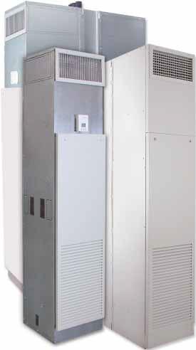
4 TVS FANCOIL UNITS VERTICAL HIGH RISE RAV Series B Features See Section 7 for dimensional drawings 4
5 Section 1 - Receipt & Initial Installation PREFACE Titus fan coils represent a prudent investment which can, with proper installation, operation, and regular maintenance, give trouble-free operation and long service. Your equipment is initially protected under the manufacturers standard warranty; however, this warranty is provided under the condition that the steps outlined in this manual for initial inspection, proper installation, regular periodic maintenance, and everyday operation of the equipment be followed in detail. This manual should be fully reviewed in advance of any actual work being done on the equipment. Should any questions arise, please contact your local Sales Representative or the factory BEFORE proceeding. The equipment covered by this manual is available with a vast variety of options and accessories. Consult the approved unit submittal, order acknowledgment, and other manuals for details on the options and accessories provided with the equipment on each project. UNPACKING & INSPECTION All units are carefully inspected at the factory throughout the manufacturing process under a detailed quality assurance program. All factory furnished major components and subassemblies are carefully tested for proper operation and verified to be in full compliance with the customer order and quality assurance documents. Each unit is then carefully packaged for shipment to avoid damage during normal transport and handling. The equipment must be stored in a dry place in the proper orientation as marked on the packaging. All shipments are made F.O.B. factory and it is the responsibility of the receiving party to inspect the equipment upon arrival. Any obvious damage to the packaging and/or its contents should be recorded on the bill of lading and a claim should be filed with the freight carrier. After determining the condition of the unit s exterior,carefully remove each unit from the packaging and inspect for hidden damage. At this time, check to make sure that ship loose items such as grilles, decorator panels, and thermostats are accounted for. Any hidden damage should be recorded and immediately reported to the carrier, and a claim filed as before. In the event a claim for shipping damage is filed, the unit, shipping package, and all packing must be retained for physical inspection by the freight carrier. All equipment should be stored in the factory shipping package with internal packing in place until installation. A series of rigorous leak tests are performed on all of the piping installed in this equipment to ensure piping integrity. Because this equipment may be shipped with factory supplied external riser piping, it is necessary for the receiving inspector to carefully inspect this piping for signs of shipping damage. If damage is present, a claim must be filed with the freight carrier. At the time of receipt, the equipment type and arrangement should be verified against the order documents. Should any discrepancy be found, the local Sales Representative should be notified immediately so that the proper action may be instituted. Should any question arise concerning warranty repairs, the factory must be notified BEFORE any corrective action is taken. Where local repairs or alterations can be accomplished, the factory must be fully informed as to the extent and expected cost of those repairs before work is begun. Where factory operations are required, the factory must be contacted for authorization to return equipment and a Return Authorization Number will be issued. Unauthorized return shipments of equipment and shipments not marked with an authorization number will be refused. In addition, the manufacturer will not accept any claims for unauthorized expenses. SHIP LOOSE ITEMS Several components are shipped loose for field installation. These may include: thermostat, return air access panel, return air access panel fasteners, discharge grille(s), risers (optional). These parts are shipped loose to offer protection against shipping and job-site damage. Refer to packing slip. HANDLING & INSTALLATION While all equipment is designed and fabricated of sturdy construction and may present a rugged appearance, great care must be taken to assure that no force or pressure be applied to the coil, risers, piping or drain stub-outs during handling. Do not use the risers for lifting the unit. Also, depending on the options and accessories, some units could contain delicate components that may be damaged by improper handling. Wherever possible, all units should be maintained in an upright position and handled by the exterior casing, with no impact forces applied that may damage internal components or painted surfaces. The equipment covered in this manual IS NOT suitable for outdoor installations. The equipment should never be stored or installed where it may be subjected to a hostile environment such as rain, snow, extreme temperatures, or hazardous chemicals. 5

6 TVS FANCOIL UNITS VERTICAL HIGH RISE Section 1 - Receipt & Initial Installation During and after installation, special care must be taken to prevent foreign material such as paint, plaster, and drywall dust from being deposited in the drain pan, electric heater, motor and blower wheels. Failure to do so may have serious adverse effects on unit operation and in the case of the heater, motor and blower assembly, may result in immediate or premature failure. All manufacturers warranties are void if foreign material is allowed to be deposited on the heater, motor or blower wheels of any unit. Some units and/or job conditions may require some form of temporary covering during construction. Condensate pan is internally sloped toward drain connection. Make assurance that unit is level and plumb. Level the unit to insure proper coil operation and condensate drainage. After units are positioned and risers centered in pipe chase, plumb the unit in two directions, using unit casing as a reference. Avoid any interference with wiring, coil, or coil connections, drain pain, and structural components inside the cabinet while using bolts or lag screws to anchor the unit to building. See Fig. 10 for critical penetration areas. After mounting the unit, it is then ready for the various service connections such as water, drain and electrical. At this time it should be verified that the proper types of service are actually provided to the unit. On those units requiring chilled water and/or hot water, the proper line size and water temperature should be available to the unit. The electrical service to the unit should be compared to the unit nameplate to verify compatibility. The routing and sizing of all piping, and the type and sizing of all wiring and other electrical components such as circuit breakers, disconnect switches, etc. should be determined by the individual job requirements and should not be based on the size and/or type of connection provided on the equipment. All installations should be made in compliance with all governing codes and ordinances. Compliance with all codes is the responsibility of the installing contractor. 6 COOLING/HEATING MEDIUM CONNECTIONS note Toxic residues and loose particles resulting from manufacturing and field piping techniques such as joint compounds, soldering flux, and metal shavings may be present in the unit and the piping system. Special consideration must be given to system cleanliness when connecting to solar,domestic or potable water systems. Submittals and Product Catalogs detailing unit operation, controls, and connections should be thoroughly reviewed BEFORE beginning the connection of the various cooling and/or heating mediums to the unit. All accessory valve packages should be installed as required, and all service valves should be checked for proper operation. If coil and valve package connections are made with sweat or solder joint, care should be taken to assure that no components in the valve package are subjected to a high temperature which may damage seals or other materials. Many two-position electric control valves, depending on valve operation, are provided with a manual-opening lever. This lever should be placed in the open position during all soldering or brazing operations. Solder joints with Sil-fos, phos-copper, or similar high temperature alloy. Do not use soft solder.
7 Section 1 - Receipt & Initial Installation FLEX HOSE All Vertical High-Rise and Twin Pack Primary & Secondary units use Kevlar reinforced braided stainless steel flexible hoses for all water piping between the coil and the risers or field piping. This factory piping includes two ball valves per coil, with memory stop. These hoses are designed with swivel connections on both ends, and require either a gasket or O-ring for positive sealing. See Fig. 1 and 2 for connection details. These hoses are designed to provide for riser movement due to thermal expansion, and allow for quick, easy coil removal through the use of the swivel connections. During transit, vibration may cause a connection to loosen. Therefore, all threaded connections must be checked during unit installation. Any fitting that is loose must be tightened. The stationary side of any swivel connection must be prevented from twisting during tightening by the use of a backup wrench. Pressure test all joints before applying water. warning Some hose-to-coil joints are furnished with a removable vulcanized fiber gasket. This gasket (Part No. PH ) must be replaced each time the joint is broken. Later model units have a hose-to-coil joint with a black EDPM gasket (Part No. PH ). This gasket is re-useable, but may be replaced should it become damaged and no longer seal. Figure 1 Flex Hose Connection Figure 2 Ball Valve with Memory Stop 7


8 TVS FANCOIL UNITS VERTICAL HIGH RISE Section 1 - Receipt & Initial Installation FACTORY INSTALLED RISERS Units provided with factory installed water and drain risers include fully insulated risers as specified per order. The flex hose and ball valve described above is assembled to the riser and pressure tested at the factory. Each unit is configured for a specific location in the building, and is marked with that location by room number, floor, riser number, or other identification as specified per order. Figure 3 Factory Installed Risers Units provided with factory installed drain risers are supplied with full height drain risers that extend 3 above the top of the unit, and include the standard swaged section at the top. Field piping and venting of the drain riser must be furnished and installed by others. Factory installed risers are strapped to the unit for shipment to prevent damage during transit. These shipping straps must be removed at installation to allow movement of the risers to assure proper alignment. See Fig. 3 and 4 for details. At no time should a unit be lifted, moved, or otherwise handled by the risers. warning Figure 4 Factory Installed Risers, Primary/Secondary Configurations FIELD PIPING EXCEPT TWIN PACK UNITS Primary Unit (Model TVSM) Secondary Unit (Model TVSS)


9 Section 1 - Receipt & Initial Installation FACTORY FURNISHED, FIELD INSTALLED RISERS Units provided with factory furnished, field installed water and drain risers include fully insulated risers as specified per order, which are shipped separately for installation on the job prior to receipt of the units. The ball valve previously described is assembled to the riser and pressure tested at the factory. The risers are packaged as a kit for a specific location in the building, and each kit is marked with that location by room number, floor, riser number, or other identification as specified per order. Figure 5 Factory Furnished, Field Installed Risers Riser kits that include drain risers are supplied with full height drain risers that extend 3 above the top of the unit, and include the standard swaged section at the top, similar to factory installed riser sets. Field piping and venting of the drain riser must be furnished and installed by others. See Fig. 5 and 6 for details. warning Field installed risers MUST be installed with the proper unit connection height and orientation to allow for correct unit installation at a later date. Swage is always oriented up. Refer to unit dimensional drawings. Figure 6 Factory Furnished, Field Installed Risers, Primary/Secondary PRIMARY UNIT (MODEL TVSM) SECONDARY UNIT (MODEL TVSS) 9
10 TVS FANCOIL UNITS VERTICAL HIGH RISE Section 1 - Receipt & Initial Installation FIELD FURNISHED AND INSTALLED PIPING OR RISERS Units provided for field furnished and installed water and drain piping or risers include the flex hose and ball valve assemblies previously described. These hose and valve assemblies include a stub of copper tube for field connection to the unit piping. The factory hose and valve assemblies are marked by connection type and retracted inside the unit for shipment. Do not braze the pipe stub without opening the ball valve and disconnecting the hose. See Fig. 7 and for details. warning Figure 7 Field Furnished and Factory Installed Risers Field fabricated/installed piping and risers MUST be installed with the proper unit connection height and orientation to allow for correct unit installation at a later date. Refer to unit dimensional drawings. RISER CONNECTION Do not rigidly attach risers to this equipment. Risers must be free to move with thermal expansion and contraction. Units and risers are designed to accommodate a maximum of 3 (1-1/2 up and 1-1/2 down) total vertical movement. To achieve this range of movement, the risers must be installed according to the conditions outlined below. If the total combined riser expansion will exceed 3, additional expansion compensation, such as loops and expansion joints, or alternate riser anchoring techniques must be field furnished and installed. Factory furnished risers are designed with a swage or socket in the top to accommodate 2 of tail piece insertion from the riser above. The riser configuration, when combined with the required length as provided by the customer, is designed to position the riser-to-unit stub out piping at the vertical center of the riser slot in the unit casing. See unit submittal drawings for dimensional details. Due to building construction variations, some risers may require cutting or lengthening to correctly position the riser. Any field modifications are the responsibility of the installer. Figure Field Furnished and Installed Risers Primary/Secondary After all connections are completed, and prior to insulating and furring-in of any riser or piping connections, the system should be tested for leaks. Since some components are not designed to hold pressure with a gas, hydronic systems should be tested with clear water. Care should be taken to completely drain the system, or otherwise protect it from freezing in cold weather. warning 10 Standard unit operating pressure is 300 psig maximum. Field test pressure must not exceed 400 psig maximum. Some optional or special unit piping components may have lower pressure ratings than the standard unit. All valve and piping component pressure ratings must be verified before applying test pressure to the unit.
11 Section 1 - Receipt & Initial Installation warning All water coils and unit piping must be protected from freezing after initial filling with water. Unit coils and piping may still hold enough water to cause damage when exposed to freezing temperatures, even after the system is drained. In the event that leaking or defective components are discovered, the sales representative must be notified BEFORE any repairs are attempted. All leaks should be repaired before proceeding with installation. After all risers and piping are installed and pressure tested, all riser joints must have the insulation joint sealed and all other piping must be insulated in compliance with the project specifications. All chilled water risers, piping, and valves must be insulated or located over a drain pan, to prevent damage from condensation. This includes factory and field piping inside the unit cabinet. Flexible duct connections should be used on all air handling equipment. All ductwork and insulation should be installed to allow proper access to all components for service and repair such as filters motor/blower assemblies, etc. DUAL AIR DISCHARGE UNITS All dual discharge units are provided with a sight and sound baffle in the discharge plenum area (except top discharge units). It is recommended that a discharge grille with a damper be provided in one of the discharge locations to aid in air balancing. Dual discharge units with top discharge must be provided with a field supplied damper in the top discharge duct. The drain should always be connected and piped to an acceptable disposal point. For proper moisture carry-off, the drain piping should be sloped away from the unit at least 1/ per foot. A drain trap is integral to the unit and is necessary for odor containment. The drain riser and piping must be installed to avoid pinching or kinking the unit drain tube. Any required piping or riser penetration fire blocking is the responsibility of the installer. All penetrations for piping and risers should be sealed with materials and techniques suitable for all governing codes and ordinances. DUCTWORK CONNECTIONS All ductwork and/or supply and return grilles should be installed in accordance with the project plans and specifications. If not included on the unit or furnished from the factory, supply and return grilles should be provided as recommend in the product catalog. All units must be installed in non-hazardous areas. Zero clearance to combustible materials is allowed. Units provided with outside air for ventilation should have some form of low temperature protection to prevent coil freeze-up. This protection may be any of several methods such as a low temperature thermostat to close the outside air damper or a preheat coil to temper the outside air before it reaches the unit. It is recommended that outside air is pretreated to regulate its temperature and humidity ratio. It should be noted that none of these methods would adequately protect a coil in the event of power failure. The safest method of freeze protection is to use glycol in the proper percent solution for the coldest expected air temperature. 11
12 TVS FANCOIL UNITS VERTICAL HIGH RISE Section 1 - Receipt & Initial Installation RISER RECONFIGURATION Vertical High-Rise units are furnished with riser slot knockouts in the casing back and both sides. Should it be necessary to relocate risers in the field, the water risers may be disconnected at the swivel joint on the riser isolation valve, and removed from the unit. The drain riser may be removed by moving the drain tube hose clamp and removing the riser tube from the drain hose. The water riser slot knockouts may be removed by clipping the tabs to separate the inner portion of the knockout. See Fig. 9 for details. After opening the riser slot, make a vertical slit in the cabinet insulation with a sharp utility knife. This slit must be centered left to right, and full height in the slot. The water riser may now be re-installed at the desired location by inserting the valve through the new opening. Insert the valve through the opening with care to avoid damage to the cabinet insulation. Make sure that the swivel joint O-ring is undamaged, and re-attach the hose to the valve with the O-ring in place. Replacement O-rings (Part No. PR ) may be ordered through the parts department. Figure 9 Knockout Removal After relocating all the risers, pressure test the joints to assure system integrity. The drain riser slot is already present on the back, left and right sides. To install the drain riser, insert the riser tube into the unit and connect the drain hose using the hose clamp preciously removed. After all the risers have been relocated, inspect the cabinet insulation where the risers were removed, and repair any insulation damage before starting the unit and cover unused openings. DISCHARGE OPENING RECONFIGURATION Vertical High-Rise and Twin Pack Primary & Secondary units are furnished with discharge opening knockouts in all four sides and the top. Should it be necessary to reconfigure a unit for a different discharge arrangement than originally provided, the new discharge opening may be created by clipping the tabs of the desired opening to remove the inner portion of the knockout. The side flanges may then be folded out to provide the drywall stops for the opening. See Fig. 9 for details. After the new opening is created, the cabinet insulation must be trimmed out, and the edges of the insulation should be coated with duct board adhesive or appropriate liner tape to prevent erosion into the air stream. Any unused discharge openings must have the drywall stops bent back flush with the unit casing. The opening must then be covered with an insulated plate. Any cover plates and insulation must be provided and installed by others. Relocating a discharge opening on a double discharge unit may require removal or relocation of any factory provided sight and sound baffle. Consult the factory for details on requirements and relocation of sight and sound baffles. 12 Size 10 and 12 units factory furnished with double discharge do not have discharge knockouts to allow field conversion to a single discharge. Consult the factory for details. warning The manufacturer assumes no responsibility for undesirable system operation due to improper field design, equipment or component selection, and/or installation of ductwork, grilles, and other related components.
13 Section 1 - Receipt & Initial Installation WALL FRAMING All wall framing is the responsibility of others. The Vertical High-Rise and Twin Pack Primary & Secondary unit casing is designed to be concealed by a finished wall or enclosure that is installed in the field by others. This enclosure may be a framed structure with gypsum board or other material covering as selected by others. Where desired, the gypsum board or paneling may be applied directly to the unit casing. If the direct application method is used, care must be taken when installing the fasteners so as not to damage any internal components. See Fig. 10 for critical penetration areas. Figure 10 Critical Penetration Areas Due to factory manufacturing tolerances and job site construction variations, some unit casing surface conditions may exist that could require additional framing or shimming of the finished wall surface. ALL WORK REQUIRED TO ACHIEVE THE DESIRED FINISHED WALL SURFACE CONDITION IS THE RESPONSIBILITY OF OTHERS. 1. Attaching fasteners should be no longer than necessary to provide proper grip 2. Do not locate fasteners where they could penetrate coils, risers, piping, electrical enclosures or other components 3. Do not locate fasteners where they would pose a safety hazard during access or service on any internal components 4. Do not locate fasteners where they would impede the access or removal of any internal component 5. Verify that all enclosure attachment points are located properly and do not pose any safety hazards or damage any internal components, before bringing the enclosure surface to finished condition (i.e. finish drywall or apply wall covering) TWIN PACK PRIMARY & SECONDARY UNIT INSTALLATION (see Section 7 for details) Twin Pack Primary & Secondary units are shipped as a factory assembled pair and are intended for installation with the space separating the units to be included in the wall between the units. Twin Pack Primary & Secondary units are available with fire rated and non-fire rated construction. Nonfire rated unit pairs may be installed as required to achieve the finished wall configuration desired. Wall framing and drywall application should be accomplished as noted above. Fire rated unit pairs are designed to be installed with the space between the units becoming part of a fire rated wall usually used to separate specific occupancies. These unit pairs must be installed according to the procedure shown on Twin Pack Primary & Secondary Installation Instructions to maintain the fire rating for the unit. 13
14 TVS FANCOIL UNITS VERTICAL HIGH RISE Section 1 - Receipt & Initial Installation OUTSIDE AIR CONNECTION The optional 6 diameter round outside air connection is provided with either a round butterfly manual damper, or a rectangular motorized damper assembly, for outside air control. See Fig. 11 for details. Installation of outside air duct connections may require installation of a vapor barrier between the unit and the wall, and may require freeze protection control devices. These components must be supplied and installed by others as required. It is recommended that all outside air be pretreated to regulate its temperature and humidity ratio. Figure 11 Outside Air Connection MANUAL OUTSIDE AIR DAMPER The manual outside air damper may be adjusted by loosening the wing nuts on the top and bottom, and setting the adjustment lever to the required position for the desired amount of outside air. The wing nuts are then tightened to lock the damper in place. MOTORIZED OUTSIDE AIR DAMPER The standard motorized outside air damper is factory wired to open the damper when the fan is operating. Other damper operating sequences are available. See individual order documents to verify actual damper operation. The motorized outside air damper is factory set to drive from full closed to full open. The damper may be adjusted in the field to set the desired amount of outside air by the following steps: 1. Loosen the set screw in the damper actuator set collar and turn on all power and set all controls to call for full outside air. This should drive the damper actuator to the full open position. 2. Manually position the damper blade to achieve the desired amount of outside air 3. Tighten the set screw to lock the damper blade to the actuator set collar 4. Disconnect power or set controls to de-energize the outside air, and verify that the damper drives to the closed position 5. Re-energize the outside air and verify that the damper returns to the position set in Step 2 14
15 Section 1 - Receipt & Initial Installation ELECTRICAL CONNECTIONS SHOCK/ELECTRICAL HAZARDS The unit nameplate lists the unit electrical characteristics such as the required supply voltage, fan and heater amperage, unit minimum circuit ampacity, and maximum overcurrent protective device. The unit wiring diagram shows all unit and field wiring. Since each project is different and each unit on a project may be different, the installer must be familiar with the wiring diagram and nameplate on the unit BEFORE beginning any wiring. Provide for adequately sized fuse, circuit breaker or disconnect means as applicable to meet local and national electrical codes. All electrical connections should be checked for tightness prior to startup. THERMOSTATS Various types of thermostats are available for this unit. Unit surface mounted thermostats are provided with a drywall mud ring for field mounting. The mud ring may be located on the unit front or either side as appropriate in the field. For remote mounted thermostats, the mud ring should be removed from the unit and reinstalled on the thermostat mounting box, or discarded as necessary. Unit surface mounted thermostats are provided with a plug assembly for easy connection. The plug is polarity specific and connects only in one direction. Remote thermostats must be field wired to unit s connection points as indicated on the unit s wiring diagram. All components furnished for field installation, by either the factory or the controls contractor should be located and checked for proper function and compatibility. All internal components should be checked for shipping damage and any loose connections should be tightened to minimize problems during startup. The fan motor(s) should never be controlled by any wiring or device other than the factory furnished switch or thermostat/switch combination, without factory authorization. Any devices such as fan speed switches or thermostats that have been furnished from the factory for field installation must be wired in strict accordance with the applicable wiring diagrams. Failure to do so could result in personal injury or damage to components and will void all manufacturers warranties. Refer to the diagram within unit. All field wiring should be done in accordance with governing codes and ordinances. Any modification of the unit wiring without factory authorization will result in voiding of all factory warranties and will nullify any agency listings. The manufacturer assumes no responsibility for any damages and/or injuries resulting from improperly field installed or wired components. 15
16 TVS FANCOIL UNITS VERTICAL HIGH RISE Section 2 Start-Up GENERAL Before beginning any start-up operation, the startup personnel should familiarize themselves with the unit, options and accessories, and control sequence to understand the proper system operation. All personnel should have a good working knowledge of general start-up procedures and have the appropriate start-up and balancing guides available for consultation. The building must be completely finished including doors, windows, and insulation. All internal walls and doors should be in place and in the normal position. In some cases the interior decorations, curtains and furniture may influence overall system performance by blocking return or supply air openings. The entire building should be as complete as possible before beginning any system balancing. Operation of the unit during construction is not recommended since construction dust will foul filters and coils and can seriously degrade unit performance. The initial step in any start-up operation should be a final visual inspection. All equipment, ductwork, and piping should be inspected to verify that all systems are complete and properly installed and mounted and that no construction debris or foreign articles such as paper or drink cans are left in the units. Each unit should be checked for loose wires, free blower wheel operation, and loose or missing access panels or doors. Except as required during start-up and balancing operations, no fan coil units should be operated without all the proper ductwork attached, supply and return grilles in place, and all access doors and panels in place and secure. A clean filter of the proper size and type must also be installed. Failure to do so could result in damage to the equipment or building and furnishings, and/or void all manufacturers warranties. 16 COOLING/HEATING SYSTEM Prior to the water system start-up and balancing, the chilled/hot water systems should be flushed to clean out dirt and debris, which may have collected in the piping during construction. During this procedure, all unit service valves must be in the closed position. This prevents foreign matter from entering the unit and clogging the valves and metering devices. Strainers should be installed in the piping mains to prevent this material from entering the units during normal operation. During system filling, air venting from the unit is accomplished by the use of the standard manual, or optional automatic, air vent fitting installed on the coil. In the case of the manual air vent fitting, the screw should be turned counterclockwise no more than 1-½ turns to operate the air vent. Automatic air vents may be unscrewed one turn counterclockwise to speed initial venting but should be screwed in for automatic venting after start-up operations warning The air vent provided on the unit is not intended to replace the main system air vents and may not release air trapped in other parts of the system. Inspect the entire system for potential air traps and vent those areas independently as required. In addition, some systems may require repeated venting over a period of time to properly eliminate air from the system. Do not exceed 300 PSIG operating pressure. warning
17 Section 2 Start-Up AIR SYSTEM BALANCING All ductwork must be complete and connected,and all grilles, filters, and access doors and panels must be properly installed to establish actual system operating conditions BEFORE beginning air balancing operations. Each individual unit and associated ductwork is a unique system with its own operating characteristics. For this reason, air balancing is normally done by balance specialists who are familiar with all procedures required to properly establish air distribution and fan system operating conditions. These procedures should not be attempted by unqualified personnel. Units without ductwork do not require air balancing other than selecting the desired fan speed. After the proper system operation is established, the actual unit air delivery and the actual fan motor amperage draw for each unit should be recorded in a convenient place for future reference such as the inspection, installation, and start-up check sheet (see Section 4). Contact the sales representative or the factory for additional copies of this sheet. CONTROLS OPERATION Before proper control operation can be verified all other systems must be in proper operation. The correct water and air temperatures must be present for the control function being tested. Some controls and features are designed not to operate under certain conditions. A wide range of controls and electrical options and accessories may be used with the equipment covered in this manual. Consult the approved unit submittals, order acknowledgment, and other manuals for detailed information regarding each individual unit and its controls. Since controls and features may vary from one unit to another, care should be taken to identify the controls to be used on each unit and their proper control sequence. Information provided by component manufacturers regarding installation, operation, and maintenance of their individual controls is available upon request. WATER SYSTEM BALANCING A complete knowledge of the hydronic system, its components, and controls is essential to proper water system balancing and this procedure should not be attempted by unqualified personnel. The system must be complete and all components must be in operating condition BEFORE beginning water system balancing operations. Each hydronic system has different operating characteristics depending on the devices and controls in the system. The actual balancing technique may vary from one system to another. After the proper system operation is established, the appropriate system operating conditions such as various water temperatures and flow rates should be recorded in a convenient place for future reference such as the inspection, installation, and start-up check sheet (see Section 4). Contact the sales representative or the factory for additional copies of this sheet. Before and during water system balancing, conditions may exist which can result in noticeable water noise or undesired valve operation due to incorrect system pressures. After the entire system is balanced, these conditions will not exist on properly designed systems. 17
18 TVS FANCOIL UNITS VERTICAL HIGH RISE Example Wiring Diagrams Typical 24 VAC Control Drawing (Refer to unit control enclosure for actual order-specific drawing) 1
19 Example Wiring Diagrams Typical 24 VAC Control Drawing (Refer to unit control enclosure for actual order-specific drawing) 19
20 TVS FANCOIL UNITS VERTICAL HIGH RISE Section 3 - Normal Operation & Periodic Maintenance GENERAL Each unit on a job will have its own unique operating environment and conditions that may dictate maintenance schedule for that unit that is different form other equipment on the job. A formal schedule of regular maintenance and an individual unit log should be established and maintained. This will help to achieve the maximum performance and service life of each unit on the job. Information regarding safety precautions contained in the preface at the beginning of this manual should be followed during any service and maintenance operations. For more detailed information concerning service operations, consult your sales representative or the factory. Figure 12 Motor/Blower Assembly MOTOR /BLOWER ASSEMBLY The type of fan operation is determined by the control components and their method of wiring, and may vary from unit to unit. Refer to the wiring diagram for each unit for that unit s individual operating characteristics. All motors have internal automatic reset thermal overloads. Should the assembly require more extensive service, the motor/blower assembly may be removed from the unit to facilitate such operations as motor or blower wheel/housing replacement, etc. The motor/ blower assembly is supplied on a slide-out rail system (see Fig. 12). To remove, loosen the two lock nuts at the rack front and slide the blower assembly out. Disconnect the motor electrical plug to fully remove the assembly from the unit. To reinstall the blower, repeat the removal sequence in reverse order. The rear of the blower must catch on the support bracket supplied. 20 Dirt and dust should not be allowed to accumulate on the blower wheel or housing. This can result in an unbalanced blower wheel condition that can damage a blower wheel or motor. The wheel and housing may be cleaned periodically using a vacuum cleaner and a brush taking care not to dislodge the factory balancing weights on the blower wheel blades. COIL Coils may be cleaned by brushing the entering air face between fins with a soft brush. Brushing should be followed by cleaning with a vacuum cleaner. If a compressed air source is available, the coil may also be cleaned by blowing air through the coil fins from the leaving air face. Vacuuming should again follow this procedure. Units provided with the proper type of air filters, replaced regularly, will still require periodic coil cleaning. ELECTRIC RESISTANCE HEATER ASSEMBLY Electric resistance heaters typically require no normal periodic maintenance when unit air filters are changed properly. The two most important operating conditions for an electric heater are proper airflow and proper supply voltage. High supply voltage and/ or poorly distributed or insufficient airflow over the element will result in element overheating. This condition may result in the heater cycling on the high limit thermal cutout. Open coil strip heaters have an automatic reset switch with a backup high limit thermal switch. Automatic reset switches are as the name implies; they reset automatically after the heater has cooled sufficiently. High limit thermal switches must be replaced once the circuit has been broken. The high limit thermal cutout device is a safety device only and is not intended for continuous operation. With proper unit application and operation, the high limit thermal cutout will not deactivate the heater. This device only operates when some problem exists and ANY condition that causes high limit cutout MUST be corrected immediately. High supply voltage also causes excessive amperage draw and may result in tripping of the circuit breaker or blowing of the fuses on the incoming power supply. warning Window treatments and drapes must not be positioned in a manner which obstructs the airflow through the return air or discharge grilles. After proper airflow and supply power are assured, regular filter maintenance is important to provide clean air over the heater. Dirt that is allowed to deposit on the heating element will cause hot spots and eventual element burn-through. These hot spots will normally not be enough to trip the thermal high limit and may not be evident until actual heater element failure. Heaters may be serviced through the unit s electrical section (see Fig. 13). To remove heater, disconnect unit power, remove heater connecting wiring and the element mounting screws.
21 Section 3 - Normal Operation & Periodic Maintenance ELECTRICAL WIRING & CONTROLS The electrical operation of each unit is determined by the components and wiring of the unit and may vary from unit to unit. Consult the wiring diagram for the actual type and number of controls provided on each unit. The integrity of all electrical connections should be verified at least twice during the first year of operation. Afterwards, all controls should be inspected regularly for proper operation. Some components may experience erratic operation or failure due to age. Wall thermostats may also become clogged with dust and lint and should be periodically inspected and cleaned to provide reliable operation. When replacing any components such as fuses, contactors, or relays, use only the exact type, size, and voltage component as furnished from the factory. Any deviation without factory authorization could result in personnel injury or damage to the unit and will void all factory warranties. All repair work should be done in such a manner as to maintain the equipment in compliance with governing codes and ordinances or testing agency listings. More specific information regarding the use and operating characteristics of the standard controls offered by this manufacturer is contained in other manuals. Figure 13 Electric Heat In the event that a valve or component should need replacement, the same precautions taken during the initial installation to protect the components from excessive heat should observed during replacement. FILTERS, THROWAWAY The type of throwaway filter most commonly used on fan coil units should be replaced on a regular basis. The time interval between each replacement should be established based on regular inspection of the filter and should be recorded in the log for each unit. Refer to the product catalog for the recommended filter size for each product type and size. If the replacement filters are not purchased from the factory, the filters used should be the same type and size as that furnished from or recommended by the factory. Consult the factory for applications using filter types other than the factory standard or optional product. Dirty filters are the cause of the most common system performance complaints. It is essential that filters be serviced on a regular basis. DRAIN The drain should be checked before initial start-up and at the beginning of each cooling season to assure that the drain trap and line are clear. If it is clogged, steps should be taken to clear the debris so that condensate will flow easily. Periodic checks of the drain should be made during the cooling season to maintain a free flowing condensate. Should the growth of algae and/or bacteria be a concern, consult an air conditioning and refrigeration supply organization familiar with local conditions for chemicals available to control these agents. The drain trap is a flexible rubber hose. It is secured to the drain pan and riser with clamps and is easily removable for service. Figure 14 Drain Pan VALVES & PIPING With the exception of strainers, no formal maintenance is required on the valve package components most commonly used with fan coil units. During normal periodic maintenance, the valve packages may be visually inspected for possible leaks. Valve packages with strainers should have the strainers cleaned after startup. The strainers may require cleaning several times immediately after startup until the system is thoroughly cleaned and stabilized. After that, a schedule should be determined for regular inspection of the strainers. 21
22 TVS FANCOIL UNITS VERTICAL HIGH RISE Section 4 Inspection, Installation & Start-Up Checklist RECEIVING & INSPECTION ʋʋ Unit Received Undamaged ʋʋ Unit Arrangement/Hand Correct ʋʋ Unit Arrangement Correct ʋʋ Unit Structural Support Complete & Correct HANDLING & INSTALLATION ʋʋ Unit Mounted Level & Square ʋʋ Proper Access Provided for Unit and Accessories ʋʋ Proper Electrical Service Provided ʋʋ Proper Overcurrent Protection Provided ʋʋ Proper Service/Switch Disconnect Provided ʋʋ Proper Chilled Water Line Size to Unit ʋʋ Proper Hot Water Line to Unit ʋʋ All services to Unit in Code Compliance ʋʋ All Shipping Screws & Braces Removed COOLING/HEATING CONNECTIONS ʋʋ Protect Protect Valve Package Components from Heat ʋʋ Mount Valve Packages ʋʋ Connect Field Piping to Unit ʋʋ Pressure Test All Piping for Leaks ʋʋ Install Drain Line & Traps as Required ʋʋ Insulate all Piping as Required DUCTWORK CONNECTIONS ʋʋ Install Ductwork, Fittings & Grilles as Required ʋʋ Proper Supply & Return Grille Type & Size Used ʋʋ Control Outside Air for Freeze Protection ʋʋ Insulate All Ductwork as Required 22 ELECTRICAL CONNECTIONS ʋʋ Refer to Unit Wing Diagram ʋʋ Connect Incoming Power Service or Services ʋʋ Electrical Service of Correct Voltage or Ampacity to Support Unit Operating Loads ʋʋ All Field Wiring Installed with Code Compliance ʋʋ Check All Wiring for Secure Connections UNIT STARTUP ʋʋ General Visual Unit & System Inspection ʋʋ Record Electrical Supply Voltage ʋʋ Record Ambient Temperature ʋʋ Close All Unit Isolation Valves ʋʋ Flush Water Systems ʋʋ Fill Systems with Water/Refrigerant ʋʋ Vent Water Systems as Required ʋʋ All Ductwork & Grilles in Place ʋʋ All Unit Panels & Filters in Place ʋʋ Start Fans, Etc. ʋʋ Check for Overload Condition of All Units ʋʋ Check All Ductwork & Units for Air Leaks ʋʋ Balance Air Systems as Required ʋʋ Record All Final Settings for Future Use ʋʋ Check Piping & Ductwork for Vibration ʋʋ Check All Dampers for Proper Operation ʋʋ Verify Proper Cooling Operation ʋʋ Verify Proper Heating Operation ʋʋ Reinstall All Covers & Access Panels
23 Section 5 Troubleshooting Symptom No Unit Operation UNIT Blows main unit or fan motor fuse when power is applied to unit FAN doesn t run with power to unit Possible Cause Corrective Action No power to unit Apply proper power to unit Improper power to unit Apply proper power to unit and check for damaged components and/or blown fuses, if furnished Power distribution panel switch or circuit breaker on OFF position Turn power distribution switch or circuit breaker to ON position Unit toggle or door interlock disconnect switch in OFF position Turn unit toggle or door interlock disconnect switch to ON position Fan switch or thermostat system switch in OFF position Turn fan switch or thermostat system switch to ON position Blown or defective unit main fuse, if furnished Check for possible defective component or improper wiring, and replace fuse Blown or defective fan motor fuse, if furnished Check for possible defective component or improper wiring, and replace fuse Defective toggle, door interlock, fan, or thermostat system switch Momentarily jumper suspected component to simulate closed contacts and achieve unit operation. Replace defective device with known good part. Loose or improper wiring from power distribution and/or remote mounted control devices Verify all wiring connections and terminations verify proper wiring of all incoming power devices and remote mounted controls Defective of improperly wired component Using a battery powered continuity tester, check for shorted or grounded components starting at incoming power. Note position of all controls during various component checks. Caution: some voltages have isolated common which may not show a short to chassis ground. Be sure to isolate each control to eliminate faulty reading through a parallel wired component. Fan switch in OFF position Turn fan switch to ON position Thermostat system switch in OFF position Turn thermostat system to ON position Remote start/stop switch in OFF position Turn remote start/stop switch to ON position Loose or improper wiring from fan switch or thermostat to unity Verify all wiring connections and terminations, and verify proper wiring of all control devices Loose or improper wiring from remote start/stop switch to unit start/stop relay Verify all wiring connections and terminations, and verify proper wiring of start/stop switch Defective fan switch Momentarily jumper fan switch to each fan speed wire to simulate proper fan switch operation. Replace defective fan switch. Defective start/stop relay Momentarily jumper start/stop relay to simulate proper relay operation. Replace defective start/stop relay. Defective fan motor Verify proper fan switch operation and replace defective fan motor 23
24 TVS FANCOIL UNITS VERTICAL HIGH RISE Section 5 Troubleshooting Symptom Fan motor hums and/or gets hot, but runs at reduced speed or not at all Possible Cause Corrective Action Improper power applied to unit Apply proper power to unit Defective motor capacitor Replace with known good capacitor Defective fan motor Replace defective motor Blower wheel jammed in housing Reposition blower wheel for proper alignment in housing, or replace if damaged Foreign object in blower wheel Remove foreign object and replace blower wheel if damaged Blower wheel dirty Remove and clean blower wheel taking care not to remove or reposition balance weights Blower wheel bent Replace blower wheel Blower wheel out of balance Replace blower wheel Foreign object in blower wheel Remove foreign object and replace blower wheel if damaged Loose motor mount screws Verify proper motor and blower wheel position and tighten motor mount screws. Do not crush mounting grommets. Broken motor mount frame or mounting screws Replace motor or mounting screws Bent blower wheel Replace blower wheel Blower wheel not positioned properly on blower shaft Check for damage to blower wheel. Reposition blower wheel on motor shaft or replace as required. Incorrect fan speed has been selected Reselect proper fan speed Dirty air filter Replace air filter Dirty coil Clean coil Obstruction in ductwork Check for improperly positioned balancing or fire dampers. Check for fallen duct liner. Repair as required. Actual E.S.P. higher than design Check installation for proper supply and/or return grilles, and compliance with plans and specifications FAN RUNS but vibrates Fan runs but blower wheel rubs housing Fan runs but air delivery is low 24
25 Section 5 Troubleshooting Symptom Fan runs but no heating (Electric heat units) Possible Cause Corrective Action No power to electric heat circuit on units with dual point power Establish power to electric heat circuit Loose or improper wiring from thermostat to electric heat contactor Verify all wiring connections and terminations, and verify proper wiring of thermostat Loose or improper wiring of electric heat element Verify all wiring connections and terminations, and verify proper wiring of electric heat element Defective electric heat contactor With electric heat contactor energized, verify proper voltage on contactor load terminals. Replace as required. Tripped or defective primary high limit switch Turn thermostat to lowest set point and allow fan to run minutes for limit switch to cool and reset. Then turn thermostat to highest set point and check for proper heating operation. If high limit trips again, check for the following conditions: improper voltage to heater element; obstructed fan or unit outlet reducing airflow over heater element; dirty or defective heater element causing hot spot. If heater does not operate after sufficient time for limit switch to cool, disconnect power and check continuously across primary high limit switch. Replace if defective. Tripped secondary high limit switch Secondary high limit switches are designed to trip only during extreme failure conditions. Contact factory before attempting any corrective action. Defective thermostat Momentarily jumper thermostat contacts to simulate proper operation. Replace thermostat as required. Defective electric heat element Disconnect power and check continuity through heat element. Replace as required. Improper aquastat or change over relay operation on units so equipped. (Note: electric heat will not operate when hot water is present at the unit) Verify proper aquastat position on piping and verify proper aquastat and change over relay operation. Replace as required. 25
26 TVS FANCOIL UNITS VERTICAL HIGH RISE Section 6: Recommended Parts List All parts listed are based on standard units. Consult the factory for replacement parts on custom units. note Miscellaneous Components PR British White Spray Paint Can (Off White) PR British White Touch-up Bottle, 6oz. (Off White) PM RB/RA P-Trap PC Drain Pan Float Switch (Models RA) PH P-Trap Tension Clips - 2 Required Thermostat Descriptions Code Control type Change over system switch fan switch Aquastat T01 2 Pipe Heat or Cool Only None None None None T02 2 Pipe Heat/Cool Auto None None Yes T03 2 Pipe Heat or Cool Only None On/Off 3 Speed None T04 2 Pipe Heat/Cool Manual Heat/Off/Cool 3 Speed Yes T05 2 Pipe Heat/Cool Auto On/Off 3 Speed Yes T06 2 Pipe Heat/Cool with Aux. Heat Manual Heat/Off/Cool 3 Speed Yes1 T07 2 Pipe Heat/Cool with Aux. Heat Auto On/Off 3 Speed Yes1 T0 2 Pipe Cool with Electric Heat Auto On/Off 3 Speed None T09 2 Pipe Cool with Electric Heat Manual Heat/Off/Cool 3 Speed None T10 4 Pipe Heat/Cool Auto None None None T11 4 Pipe Heat/Cool Auto On/Off 3 Speed None T12 4 Pipe Heat/Cool Manual Heat/Off/Cool 3 Speed None Note: 1. Other devices may be required for 2 Pipe changeover applications. Thermostat, Wall Mounted1 Unit Surface Mount Wiring Harness Code Part Number Part Number T03 PC T05 PC T06 PC T07 PC T0 PC T09 PC T11 PC T12 PC Note: 1. Includes Model RA unit surface mount. Aquastatd 26 Part Number Description PC Aquastat, with Mounting Clip, 5/ inch pipe
27 Section 6: Recommended Parts List Filters Unit size Nominal filter size Throwaway filter part # Unit size Nominal filter size 03/ x 14 x 1 PM / x 24 x 1 PM / x 24 x 1 PM / x 26 x 1 PM / x 29 x 1 PM / x 29 x 1 PM MODEL RA (Series A) Throwaway filter part # MODEL RA (Series B) Motorized Outside Air Damper Actuators Voltage LH UNIT (CW) 24 PC PC /230 PC Contact Factory Notes: 1. TVS Fan Assembly includes housing, cut off and wheel. Order motor and/or capacitor separately. 2. TVS Fan Assembly available as an assembly only 3. TVS Fan Assembly is standard fan assembly only TVS Fan Assembly1 Unit Size Assembly 03 B B B B B B Fan Coil 3-Speed Motors, Model TVS Unit Size Series A Series B Motor Capacitor Motor Capacitor HP Voltage Part # Value Part # HP Voltage Part # Value Part # 1/ PM uf 370V PE / PM uf 370V PE / PM uf 370V PE / PM uf 370V PE /25 27 PM uf 370V PE / PM uf 370V PE / PM uf 370V PE / PM uf 370V PE / PM uf 370V PE / PM uf 370V PE / PM uf 370V PE / PM uf 370V PE / PM uf 370V PE / PM uf 370V PE / PM uf 370V PE / PM uf 370V PE / PM uf 370V PE / PM uf 370V PE /6 115 PM uf 370V PE /6 115 PM uf 370V PE /6 230 PM uf 370V PE /6 230 PM uf 370V PE /6 277 PM uf 370V PE /6 277 PM uf 370V PE /5 115 PM uf 370V PE /5 115 PM uf 370V PE /5 230 PM uf 370V PE /5 230 PM uf 370V PE /5 277 PM uf 370V PE /5 277 PM uf 370V PE /4 115 PM uf 370V PE /4 115 PM uf 370V PE /4 230 PM uf 370V PE /4 230 PM uf 370V PE /4 277 PM uf 370V PE /4 277 PM uf 370V PE
28 TVS FANCOIL UNITS VERTICAL HIGH RISE Section 6: Recommended Parts List Water Coil Assemblies, Model TVS (Series A) Unit Size 03 / / 0 10 / 12 Coil Rows B R-DG 4 Row Cooling B R-DG 3 Row Cooling/1 Row Heating B74-201R-DG 3 Row Cooling/2 Row Heating B R-DG 4 Row Cooling/1 Row Heating B R-DG 3 Row Cooling B R-DG 4 Row Cooling B R-DG 3 Row Cooling/1 Row Heating B R-DG 3 Row Cooling/2 Row Heating B R-DG 4 Row Cooling/1 Row Heating B R-DG 3 Row Cooling B R-DG 4 Row Cooling B74-200R-DG 3 Row Cooling/1 Row Heating B R-DG 3 Row Cooling/2 Row Heating B R-DG 4 Row Cooling/1 Row Heating B R-DG 06 / 0 10 / 12 2 Coil Rows 3 Row Cooling 4 Row Cooling 3 Row Cooling/1 Row Heating 3 Row Cooling/2 Row Heating 4 Row Cooling/1 Row Heating 3 Row Cooling 4 Row Cooling 3 Row Cooling/1 Row Heating 3 Row Cooling/2 Row Heating 4 Row Cooling/1 Row Heating 3 Row Cooling 4 Row Cooling 3 Row Cooling/1 Row Heating 3 Row Cooling/2 Row Heating 4 Row Cooling/1 Row Heating Description Part # Hose (Standard) PC Part # 3 Row Cooling unit size 03 / 04 RA Riser-to-Coil Hose Assembly Adapter Fitting PR Gasket PH or 004* Unit Isolation Ball Valve PC Viton O-Ring PR Notes: 1. Coils are galvanized casing only, contact Titus sales representative for specials 2. High GPM circuiting refers to CW coil only 3. All heating coils are in reheat position Fan Coil 3-Speed Motors, Model TVS Standard Circuiting # of Ckts. Part # # of Ckts. 1 B R-DG 2 1 B R-DG 2 1 B74-211R-DG 2 1 B R-DG 2 1 B R-DG 2 2 B R-DG 3 2 B R-DG 3 2 B R-DG 3 2 B R-DG 3 2 B R-DG 3 3 B R-DG 4 3 B74-210R-DG 4 3 B R-DG 4 3 B R-DG 4 3 B R-DG 4 Part # B R-DG B R-DG B R-DG B R-DG B R-DG B R-DG B R-DG B R-DG B R-DG B74-212R-DG B R-DG B R-DG B R-DG B R-DG B R-DG High GPM Circuiting # of Ckts Part # -----B R-DG B R-DG B74-213R-DG B R-DG B R-DG
29 Section 6: Recommended Parts List Valve package bodies and actuators valve body Part # valve actuators, standard Vendor # Description Part # Vendor # Voltage PC vt Way NC 1/2 Std. Body PC AG13A volt PC VT Way NC 1/2 Std. Body PC AG13B volt PC AG13D volt PC AG13U volt PC AG13T volt TVS (series A) steel double deflection supply registers Unit Size Nominal Grille Size Part # 03 & x 6 PM & 0 1 x PM PM & 12 (Single) 22 x & 12 (Double) 22 x PM & 04 w/obd1 16 x 6 PM & 0 w/obd1 1 x PM & 12 w/obd1 22 x PM TVS Aluminum double deflection supply registers Series A Unit Size Series B Nominal Grille Size Part # Nominal Grille Size part # 03 & x 6 PM x PM & 0 1 x PM x 12 PM PM & 12 (Single) 22 x 14 PM x & 12 (Double) 22 x PM x 12 PM & 04 w/obd1 16 x 6 PM x PM & 0 w/obd1 1 x PM x 12 PM & 12 w/obd1 22 x PM x 12 PM Notes: 1. Opposed blade dampers (OBD) are used for air balancing purposes on double supply units. Only one may be used per unit and must not be used in any circumstance for single supply registers. TVS Aluminum Double deflection supply registers Series A assemblies Series B assemblies Unit Size Standard Recessed Standard Recessed Unit Size STD. Panel w/ada Tstat w/tmpr. Resist Latch w/ada Tstat & Tmpr. Resist Latch Std.Panel w/ada Tstat w/tmpr. Resist Latch w/ada Tstat & Tmpr. Resist Latch Std. quick open latch assy PH Tamper Resistant Latch Parts Shaft PH Trim Washer PH Pawl Assembly PH Push-On Retainer PH
30 TVS FANCOIL UNITS VERTICAL HIGH RISE Example Wiring Diagrams TVSR Vertical Stack High-Rise Recessed Fan Coil Unit TVSR Vertical Stack High-Rise Recessed Fan Coil Unit 30 Unit Size A B 03 & 04 1 [457] 06 & 0 10 & 12 Single/Double Supply E C D 16 1/2 [419] 16 [406] 6 [152] 20 [50] 1 1/2 [470] 1 [457] 12 [305] 6 [152] 24 [610] 22 1/2 [572] 22 [559] 14 [356] Notes: 1. All dimensions are in inches [mm]. Metric values are soft conversion. 2. All dimensions are ± 1/4 [6mm] 3. Tile ring is installed on front of unit as shown, and may be moved to left or right side of unit in field. Tile ring omitted on units with ADA control mounting location. 4. Wiring from electrical entry point to control enclosure is furnished and installed by others in field 5. Risers available from 3/4 [19mm] to 3 [76mm] diameter with 1/2 [13mm] thick insulation, and 3/4 [19mm] to 2-1/2 [64mm] diameter with 3/4 [19mm] thick insulation. 6. Riser length is 120 [304mm] max. 100 [2540mm] min. 7. Back riser location shown. See arrangement drawings for available unit configurations.. Factory mounted risers shown
31 Example Wiring Diagrams TVSM Vertical Stack High-Rise Primary Shipped Seperate Fan Coil Unit TVSM Vertical Stack High-Rise Primary Fan Coil Unit Unit Size A B 03 & 04 1 [457] 06 & 0 10 & 12 Single/Double supply E C D 16 1/2 [419] 16 [406] 6 [152] 20 [50] 1 1/2 [470] 1 [457] 12 [305] 6 [152] 24 [610] 22 1/2 [572] 22 [559] 14 [356] Notes: 1. All dimensions are in inches [mm]. Metric values are soft conversion. 2. All dimensions are ± 1/4 [6mm] 3. Tile ring is installed on front of unit as shown, and may be moved to left or right side of unit in field. Tile ring omitted on units with ADA control mounting location. 4. Wiring from electrical entry point to control enclosure is furnished and installed by others in field 5. Risers available from 3/4 [19mm] to 3 [76mm] diameter with 1/2 [13mm] thick insulation, and 3/4 [19mm] to 2-1/2 [64mm] diameter with 3/4 [19mm] thick insulation. 6. Riser length is 120 [304mm] max. 100 [2540mm] min. 7. Back riser location shown. See arrangement drawings for available unit configurations.. Factory mounted risers shown 31
32 TVS FANCOIL UNITS VERTICAL HIGH RISE Example Wiring Diagrams TVRS Vertical Stack High-Rise Secondary Shipped Seperate Fan Coil Unit TVSS Vertical Stack High-Rise Primary Fan Coil Unit 32 Unit Size A B 03 & 04 1 [457] 06 &0 10 &1 2 Single supply E C D 16 1/2 [419] 16 [406] 6 [152] 20 [50] 1 1/2 [470] 1 [457] 12 [305] 6 [152] 24 [610] 22 1/2 572] ] 14 [356] Notes: 1. All dimensions are in inches [mm]. Metric values are soft conversion. 2. All dimensions are ± 1/4 [6mm] 3. Tile ring is installed on front of unit as shown, and may be moved to left or right side of unit in field. Tile ring omitted on units with ADA control mounting location. 4. Wiring from electrical entry point to control enclosure is furnished and installed by others in field 5. Risers available from 3/4 [19mm] to 3 [76mm] diameter with 1/2 [13mm] thick insulation, and 3/4 [19mm] to 2-1/2 [64mm] diameter with 3/4 [19mm] thick insulation. 6. Riser length is 120 [304mm] max. 100 [2540mm] min. 7. Back riser location shown. See arrangement drawings for available unit configurations.. Factory mounted risers shown


33 Example Wiring Diagram TVSM/TVSS Vertical Stack High-Rise Twin Pack Coil Unit TVSM PRIMARY TVSS SECONDARY 33
34 TVS FANCOIL UNITS VERTICAL HIGH RISE Example Wiring Diagrams TVSM/TVSS Vertical Stack High-Rise Twin Pack Fan Coil Unit TVSM/TVSS unit cabinet dimensions Supply Air TVSM (Primary) TVSS (Secondary) A 03 & & 04 1 [457] 42 1/4 [1073] 16 1/2 [419] 03 & & 0 20 [50] 46 1/4 [1175] 03 & & [610] 06 & 0 03 & & 0 06 & 0 06 & 0 10 & & & & & 0 10 & & 12 B C D Single /Double Top E F G 16 [406] 6 [152] 1 1/2 [470] 1 [457] 12 [305] 6 [152] 12 [305] 54 1/4 [137] 22 1/2 [572] 22 [559] 14 [356] 14 [356] 20 [50] 46 1/4 [1175] 1 1/2 [470] 1 [457] 12 [305] 6 [152] 12 [305] 24 [610] 54 1/4 [137] 22 1/2 [572] 22 [559] 14 [356] 14 [356] 24 [610] 54 1/4 [137] 22 1/2 [572] 22 [559] 14 [356] 14 [356] Notes: 1. All dimensions are in inches [mm]. Metric values are soft conversion. 2. All dimensions are ± 1/4 [6mm] 3. Thermostat mounting Tile ring is installed on front of unit as shown, and may be moved to left or right side of unit in field. 4. Wiring from electrical entry point to control enclosure is furnished and installed by others in field 5. Risers available from 3/4 [19mm] to 3 [76mm] diameter with 1/2 [13mm] thick insulation, and 3/4 [19mm] to 2-1/2 [64mm] diameter with 3/4 [19mm] thick insulation. 6. Riser length is 120 [304mm] max. 100 [2540mm] min 7. Back riser location shown. See arrangement drawings for available unit configurations.. Factory mounted risers shown 34
35 Example Wiring Diagram TVSR Vertical Stack High-Rise 79" Recessed Fan Coil Unit Notes: 1. All dimensions are in inches [mm]. Metric values are soft conversion. 2. All dimensions are ± 1/4 [6mm] 3. Tile ring is installed on front of unit as shown, and may be moved to left or right side of unit in field. Tile ring omitted on units with ADA control mounting location. 4. Wiring from electrical entry point to control enclosure is furnished and installed by others in field 5. Risers available from 3/4 [19mm] to 3 [76mm] diameter with 1/2 [13mm] thick insulation, and 3/4 [19mm] to 2-1/2 [64mm] diameter with 3/4 [19mm] thick insulation. 6. Riser length is 120 [304mm] max. 100 [2540mm] min. 7. Back riser location shown. See arrangement drawings for available unit configurations.. Single supply size 10 and 12 available in top discharge only 9. Factory mounted risers shown Unit Size A B C 03 & 04 1 [457] 23 3/ [594] 06 & 0 20 [50] 10 & [610] Single Supply Double Supply Top Supply D E D E D E F 16 1/2 [419] 16 [406] 16 [406] 16 [406] 6 [152] 25 3/ [645] 1 1/2 [470] 1 [457] 1 [457] 1 [457] 1 [457] 12 [305] 6 [152] 29 3/ [746] 22 1/2 [572] -- [--] -- [--] 22 [559] 22 [559] 12 [305] 35
36 TVS FANCOIL UNITS VERTICAL HIGH RISE Example Wiring Diagrams TVSR - Vertical Concealed High-Rise 79 Primary Shipped Seperate Fan Coil Unit Notes: 1. All dimensions are in inches [mm]. Metric values are soft conversion. 2. All dimensions are ± 1/4 [6mm] 3. Tile ring is installed on front of unit as shown, and may be moved to left or right side of unit in field. Tile ring omitted on units with ADA control mounting location. 4. Wiring from electrical entry point to control enclosure is furnished and installed by others in field 5. Risers available from 3/4 [19mm] to 3 [76mm] diameter with 1/2 [13mm] thick insulation, and 3/4 [19mm] to 2-1/2 [64mm] diameter with 3/4 [19mm] thick insulation. 6. All piping and insulation between Primary and Secondary units is furnished and installed in the field by others. 7. Riser length is 120 [304mm] max. 100 [2540mm] min.. Back riser location shown. See arrangement drawings for available unit configurations. 9. Single supply size 10 and 12 available in top discharge only 10. Secondary unit stubout dimension is approximate and varies with riser diameter. Stubout extends approximately 4 from riser tube. 11. Water piping connections are 5/ [16mm] O.D. and drain connection is 7/ [22mm] O.D. 12. Factory mounted risers shown 36 Unit Size A B C 03 & 04 1 [457] 24 [610] 06 & 0 20 [50] 10 & [610] single supply double supply top supply D E D E D E F 16 1/2 [419] 16 [406] 16 [406] 16 [406] 6 [152] 26 [660] 1 1/2 [470] 1 [457] 1 [457] 1 [457] 12 [305] 6 [152] 30 [762] 22 1/2 [572] -- [--] -- [--] 22 [559] 22 [559] 12 [305]
37 Example Wiring Diagram TVRS Vertical Concealed High-Rise 79 Secondary Shipped Seperate Fan Coil Unit Notes: 1. All dimensions are in inches [mm]. Metric values are soft conversion. 2. All dimensions are ± 1/4 [6mm] 3. Tile ring is installed on front of unit as shown, and may be moved to left or right side of unit in field. Tile ring omitted on units with ADA control mounting location. 4. Wiring from electrical entry point to control enclosure is furnished and installed by others in field 5. All piping and insulation between Primary and Secondary units is furnished and installed in the field by others. 6. Back connection location shown. See arrangement drawings for available unit configurations. 7. Single supply size 10 and 12 available in top discharge only. All coil and drain connections are retracted and braced internally for shipment 9. Coil connections are 5/ [16mm] O.D. female sweat. Drain P-Trap is designed to accept 7/ [22mm] O.D. copper tube. 10. Secondary units are furnished with factory installed shutoff valves and field connection tubes, unless Primary unit risers are shipped loose. Unit Size A B C 03 & 04 1 [457] 16 1/2 [419] 06 & 0 20 [50] 10 & [610] Single Supply Double Supply Top Supply D E D E D E F 16 [406] 16 [406] 16 [406] 6 [152] 6 [152] 1 1/2 [470] 1 [457] 1 [457] 1 [457] 12 [305] 6 [152] 6 [152] 22 1/2 [572] -- [--] -- [--] 22 [559] 22 [559] 12 [305] 37


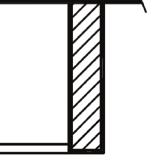
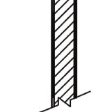
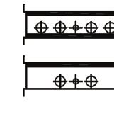
![Risers available from 3/4 [19mm]](/docs-images/82/86765028/images/38-41.jpg "to 3 [76mm] diameter with 1/2")
![[13mm] thick insulation, and 3/4](/docs-images/82/86765028/images/38-43.jpg "[19mm] to 2-1/2 [64mm] diameter")
![with 3/4 [19mm] thick insulation.](/docs-images/82/86765028/images/38-44.jpg "6. Riser length is 120 [304mm]")
![max. 100 [2540mm] min. 7.](/docs-images/82/86765028/images/38-46.jpg "NON-FIRE RATED unit shown with")


38 TVS FANCOIL UNITS VERTICAL HIGH RISE Example Wiring Diagrams TVSM/TVSS - Vertical High-Rise 79 Fire Rated and Non-Fire Rated Fan Coil Unit TVSM PRIMARY TVSS SECONDARY Notes: 1. All dimensions are in inches [mm]. Metric values are soft conversion. 2. All dimensions are ± 1/4 [6mm] 3. Thermostat mounting Tile ring is installed on front of unit as shown, and may be moved to left or right side of unit in field. 4. Wiring from electrical entry point to control enclosure is furnished and installed by others in field 5. Risers available from 3/4 [19mm] to 3 [76mm] diameter with 1/2 [13mm] thick insulation, and 3/4 [19mm] to 2-1/2 [64mm] diameter with 3/4 [19mm] thick insulation. 6. Riser length is 120 [304mm] max. 100 [2540mm] min. 7. NON-FIRE RATED unit shown with type X gypsum board at back of Secondary unit. FIRE RATED units have type X gypsum board at back of both Secondary and Primary units. FIRE RATED unit design has been tested in accordance with UL1479 Fire Tests Of Through Penetration Fire Stops, and is approved to bear the ETL listing mark for Through Penetration Fire Stop Assemblies.. For further fire rating information refer to the installation instructions, page 5 9. See page 40 for dimensions 10. Refer to pages for Twin Pack Primary & Twin Pack Secondary configurations 3
39 Example Wiring Diagram TVSM/TVSS High-Rise unit cabinet dimensions TVSM supply air TVSM (Primary) TVSS (Secondary) A 03 & & 04 1 [457] 42 1/4 [1073] 16 1/2 [419] 03 & & 0 20 [50] 46 1/4 [1175] 03 & & [610] 06 & 0 03 & & 0 06 & 0 06 & 0 10 & & & & &0 10 & & 12 TVSS Supply Air Single Double Single Double E E F G E E F G 16 [406] 6 [152] 6 [152] 1 1/2 [470] 1 [457] 6 [152] 6 [152] 12 [305] 6 [152] 12 [305] 54 1/4 [137] 22 1/2 [572] 22 [559] 12 [305] -[--] 12 [305] 20 [50] 46 1/4 [1175] 1 1/2 [470] 1 [457] 6 [152] 12 [305] 6 [152] 12 [305] 24 [610] 54 1/4 [137] 22 1/2 [572] 22 [559] 12 [305] -[--] 12 [305] 24 [610] 54 1/4 [137] 22 1/2 [572] 22 [559] -[--] 12 [305] -[--] 12 [305] B C D Top Top All dimensions in inches [mm] See page 39 for notes 39
40 TVS FANCOIL UNITS VERTICAL HIGH RISE Example Wiring Diagrams TVS Double Deflection Aluminum Discharge Grille Model Type Unit Size 03 or 04 Type Vertical High-Rise & Twin Pack Primary and Secondary Same Size Units 06 or 0 Cabt. Hgt. Single/Double Supply W H A B 16 [406] 17 11/16 [449] 19 11/16 [500] Std 1 [457] 12 [305] 19 11/16 [500] 13 11/16 [34] 79 Cabt. 1 [457] 19 11/16 [500] 9 11/16 [246] Std 22 [559] 14 [356] 23 11/16 [602] 15 11/16 [39] 79 Cabt Std 79 Cabt. 10 or 12 Model Type Unit Size Cabt. Hgt. Std Single/Double Supply W H A B 1 [457] 12 [305] 19 11/16 [500] 19 11/16 [500] 03 or Cabt. Twin Pack Primary and Secondary Same Size Units 06 or 0 Std 79 Cabt. 10 or 12 Std 79 Cabt [457] 19 11/16 [500] 19 11/16 [500] 22 [559] 14 [356] 23 11/16 [602] 15 11/16 [39] [559] 14 [356] 23 11/16 [602] 15 11/16 [39] Notes: 1. All dimensions are inches [mm]. Metric values are soft conversion. 2. All dimensions are ± 1/4 [6mm] 3. Discharge grilles are shipped loose for field installation 4. Construction is aluminum frame and blades 5. Standard finish is powder coat baked enamel. Color is British White. 6. Installation of grilles on adjacent unit sides may require furring on side away from unit to prevent interference of frames 7. Mounting hardware included
41 Arrangement Drawing TVSR/TVRM/TVSM Vertical High-Rise Fan Coil Unit Arrangement Designations 41
42 TVS FANCOIL UNITS VERTICAL HIGH RISE Arrangement Drawing TVSR w/o Risers & TVRS/TVSS Vertical High-Rise Fan Coil Unit Arrangement Designations 42
43 Arrangement Drawing TVS Vertical High-Rise Fan Coil Unit Outside Inlet Dimensions Notes: Return air and access are always on front of unit This drawing shows available return and outside air inlet locations See arrangement drawings for complete unit riser supply, and return configuration details. Outside air inlet location is always last character in arrangement code TVSR unit with optional riser chase shown. Outside air location designations are typical for all TVS models. 43


44 TVS FANCOIL UNITS VERTICAL HIGH RISE Arrangement Drawing TVRM/TVSM/TVSR Twin Pack Primary & Secondary Configuration TYPICAL UNIT ARRANGEMENTS Shown above Non-Fire Rated TYPICAL UNIT ARRANGEMENTS Notes: 1. For other possible combinations see pages Fire rated units shown. Non-fire rated is standard. 3. See twin-pack Primary & Twin-Pack Secondary installation instructions, pages 56 & Sight and sound baffles provided as required TWIN PACK PRIMARY & SECONDARY FIRE RATED TWIN PACK PRIMARY & SECONDARY NON-FIRE RATED PRIMARY UNIT SECONDARY UNIT 44
45 Arrangement Drawing TVSM / TVSR / TVRS Assembly Instructions Return Panel with Latches, Quick Opening or Tamper Proof 45


46 TVS FANCOIL UNITS VERTICAL HIGH RISE Arrangement Drawing TVRS Ship In Advance Riser Assembly - Preparation Instructions MODEL TVRS SECONDARY UNIT VALVE SHIPS LOOSE MODEL TVRS SECONDARY UNIT RISER STUB-OUT TUBE AS REQUIRED Notes: 1. All risers and valves are shipped with protective caps. These caps should remain in place until installation of the unit. 2. Each valve is supplied with an O-ring that is bagged and shipped loose for field installation by others 3. All risers are factory tested, and guaranteed to be leak free at time of shipment 4. Riser information shown shall reflect matching unit identification labels 5. TVRS, Secondary units will have mirror image orientation and will be labeled in units 6. Condensate P-Trap and hose clamps ships installed in unit for field connections to drain riser 46
SERIES B VERTICAL FLOOR FAN COIL UNIT
 BY JOHNSON CONTROLS Installation, Operation & Maintenance SERIES B VERTICAL FLOOR FAN COIL UNIT New Release Form ET115.24-NOM9 (908) Model VFC/VFE/VFS TABLE OF CONTENTS TABLE OF CONTENTS...2 SAFETY SYMBOLS...3
CDH/CDV Horizontal and Vertical Direct Drive Air Handling Units
 ~~~~~~~~~~~~~~~~~~~~~~~~~~~~~~~~~~ CDH/CDV Horizontal and Vertical Direct Drive Air Handling Units INSTALLATION, OPERATION AND MAINTENANCE MANUAL Stock ID: IOM-BCUDD June, 2001 2001 Environmental Technologies,
Vertical Concealed Fan Coil. FCVC Series MANUAL INSTALLATION, OPERATION, & MAINTENANCE
 MANUAL INSTALLATION, OPERATION, & MAINTENANCE Vertical Concealed Fan Coil FCVC Series v100 Issue Date: 12/21/15 2015 Price Industries Limited. All rights reserved. TABLE OF CONTENTS Product Overview Safety
Modular Hi-Rise Series Fan Coils INSTALLATION, OPERATION, & MAINTENANCE MANUAL
 Modular Hi-Rise Models: MPY, MXY, MAY/MBY Ditto, MMY/MSY, MUY, and MGY BUILD YOUR REPUTATION ON OURS International Environmental Corporation (IEC) works continually to improve its products. As a result,
RBV Installation Manual
 FAN COIL UNITS VERTICAL FLAT TOP CABINET RBV Installation Manual SO TOUGH, WE GUARANTEE IT. RBVR RBVC RBVS www.superiorrex.com Table of Contents Table Of Contents...2 Safety Symbols...3 Safety Considerations...3
CROWN. Boiler Co. Santa-Fe Series. Hydronic Air Handlers INSTALLATION, OPERATION & MAINTENANCE INSTRUCTIONS
 CROWN Boiler Co Santa-Fe Series Hydronic Air Handlers INSTALLATION, OPERATION & MAINTENANCE INSTRUCTIONS These instructions must be affixed on or adjacent to the air handler Models: SAC049A20 SAC059A25
Installation, Operating & Maintenance Instructions. Horizontal Models: LH & HL
 Installation, Operating & Maintenance Instructions Horizontal Models: LH & HL Table of Contents Table of Contents... 2 Product Safety... 2 Important Information About Safety Instructions... 2 Receiving...
SERIES C VERTICAL FLOOR FAN COIL UNIT
 SERIES C VERTICAL FLOOR FAN COIL UNIT Installation, Operation & Maintenance New Release Form 115.24-NOM10 (1210) Model FWC/FWX/FWI TABLE OF CONTENTS TABLE OF CONTENTS...2 SAFETY SYMBOLS...3 SAFETY CONSIDERATIONS...4
Installation, Operating & Maintenance Instructions. Air Handler Models: AH & AV
 Installation, Operating & Maintenance Instructions Air Handler Models: AH & AV Table of Contents Table of Contents... 2 Product Safety... 2 Important Information About Safety Instructions... 2 Receiving...
HP SERIES HPP Plenum Return Shown
 HP SERIES FAN COILS INSTALLATION, OPERATION & MAINTENANCE Supersedes ET115.24-NOM1 (511) Form ET115.24-NOM1 (615) HP SERIES HPP Plenum Return Shown INTRODUCTION ENVIRO-TEC fan coils represent a prudent
Installation & Maintenance Data IM Contents
 Installation & Maintenance Data IM 254-4 Group: Fan Coil Part Number: 107133000 Date: June 1999 SeasonMaker HiLine Fan-coil Units Type KZZ Contents Inspection..................................... 2 Riser
KHGE INSTALLATION GUIDE. Installation, Assembly, Start-up, and Service Instructions
 KHG Series KHGE KHGH KHGP INSTALLATION GUIDE Installation, Assembly, Start-up, and Service Instructions Page: 2 of 38 Page: 3 of 38 TABLE OF CONTENTS General Safety Guidelines & Safety Symbols Section
SeasonMaker Hi-Line Fan-coil Unit Model HSS S30 through S80
 Installation & Maintenance Data IM 255-6 SeasonMaker Hi-Line Fan-coil Unit Model HSS S30 through S80 Group: Fan coil Part Number: # 106332400 Date: August 2000 Table of Contents Inspection............................................................................
Vertical Stack Fan Coil Units Models: TVA, TVE, TVS
 6720 Columbus Road Mississauga, Ontario Canada, L5T 2G1 Tel: (905) 670 3595 Fax: (905) 670 3592 www.temspec.com Vertical Stack Fan Coil Units Models: TVA, TVE, TVS INSTALLATION, OPERATION AND MAINTENANCE
WMHP Series R410a Heat Pump INSTALLATION INSTRUCTIONS
 WMHP Series R410a Heat Pump INSTALLATION INSTRUCTIONS **WARNING TO INSTALLER, SERVICE PERSONNEL AND OWNER** Altering the product or replacing parts with non authorized factory parts voids all warranty
SeasonMaker Hi-Line Fan-coil Units Model HSS S10 & S12
 Installation & Maintenance Data IM 168-5 SeasonMaker Hi-Line Fan-coil Units Model HSS S10 & S12 Group: Fan coil Part Number: # 107132900 Date: June 1999 Table of Contents Inspection............................................................................
TEMSPEC INC. VERTICAL FAN COIL UNIT MODELS TVA, TVE, TVS
 6720 Columbus Road Mississauga, Ontario Canada, L5T 2G1 Tel: (905) 670 3595 Fax: (905) 670 3592 Web: www.temspec.com TEMSPEC INC. VERTICAL FAN COIL UNIT MODELS TVA, TVE, TVS INSTALLATION AND MAINTENANCE
Installation, Operating & Maintenance Instructions. Vertical Stack Models: ER & DR
 Installation, Operating & Maintenance Instructions Vertical Stack Models: ER & DR Table of Contents Table of Contents... 2 Product Safety... 2 Important Information About Safety Instructions... 2 Receiving...
SPX SERIES PACKAGED AIR CONDITIONING/HEAT PUMP UNITS INSTALLATION, OPERATION AND MAINTENANCE INSTRUCTIONS
 SPX SERIES PACKAGED AIR CONDITIONING/HEAT PUMP UNITS INSTALLATION, OPERATION AND MAINTENANCE INSTRUCTIONS **WARNING TO INSTALLER, SERVICE PERSONNEL AND OWNER** Altering the product or replacing parts with
FAN POWERED VAV TERMINALS
 FAN POWERED VAV TERMINALS Models VFR, CFR and CFRQ INSTALLATION, OPERATION AND MAINTENANCE MANUAL All data herein is subject to change without notice. Refer to www.enviro-tec.com for current catalog data
Energy Efficient Easy to Install Extended Service Life. Horizontal Direct Drive Blower Coils
 INSTALLATION, OPERATIONS AND MAINTENANCE MANUAL Energy Efficient Easy to Install Extended Service Life Energy efficient compact blower coils Ideal for educational, hospitality, multi-family, or other commercial
Installation, Operating & Maintenance Instructions. High Performance Horizontal Models: HH & CH
 Installation, Operating & Maintenance Instructions High Performance Horizontal Models: HH & CH Table of Contents Table of Contents... 2 Product Safety... 2 Important Information About Safety Instructions...
Horizontal & Horizontal Quiet Blower Coils
 MANUAL INSTALLATION Horizontal & Horizontal Quiet Blower Coils BCH / BCHQ Series v200 Issue Date: 05/19/15 2015 Price Industries Limited. All rights reserved. TABLE OF CONTENTS Product Overview Safety
T-Series Air Conditioner T15 Model
 INSTRUCTION MANUAL T-Series Air Conditioner T15 Model Protecting Electronics. Exceeding Expectations. McLean Cooling Technology 11611 Business Park Blvd N Champlin, MN 55316 USA Tel 763-323-8200 Fax 763-576-3200
T-SERIES Air Conditioner. T20 Model INSTRUCTION MANUAL nvent Rev. C P/N
 T-SERIES Air Conditioner T20 Model INSTRUCTION MANUAL Rev. C P/N 89114993 TABLE OF CONTENTS Warranty and Return Policy... 2 IMPORTANT NOTICE... 2 RECEIVING THE AIR CONDITIONER... 3 HANDLING AND TESTING
Installation Instructions. For the 18 Built-In Dishwasher and Front Color Panels
 Installation Instructions For the 18 Built-In Dishwasher and Front Color Panels Printed in USA 154232102 Before You Begin DO NOT INSTALL DISHWASHER UNTIL YOU HAVE READ ALL INSTRUCTIONS. FOR YOUR SAFETY,
VERTICAL HIGH OUTPUT VHC-IOM INSTALLATION AND MAINTENANCE INSTRUCTIONS VHC INSTALLER MUST BE A TRAINED, EXPERIENCED SERVICE TECHNICIAN
 VHC INSTALLER MUST BE A TRAINED, EXPERIENCED SERVICE TECHNICIAN 1. PRESSURE CHECK When the valve package is factory installed, the unit is shipped with the coil and associated piping/valve package pressurized.
T-SERIES Air Conditioner. T43 Model INSTRUCTION MANUAL nvent Rev. I P/N
 T-SERIES Air Conditioner T43 Model INSTRUCTION MANUAL Rev. I P/N 10-1008-145 TABLE OF CONTENTS Warranty and Return Policy...2 IMPORTANT NOTICE...2 RECEIVING THE AIR CONDITIONER...3 HANDLING AND TESTING
SPECTRACOOL Air Conditioner. N21 Model INSTRUCTION MANUAL nvent Rev. G P/N
 SPECTRACOOL Air Conditioner N21 Model INSTRUCTION MANUAL Rev. G P/N 89115088 TABLE OF CONTENTS WARRANTY AND RETURN POLICY...2 RECEIVING THE AIR CONDITIONER...3 HANDLING AND TESTING THE AIR CONDITIONER...3
T-Series Air Conditioner T20 Model
 INSTRUCTION MANUAL T-Series Air Conditioner T20 Model Protecting Electronics. Exceeding Expectations. McLean Cooling Technology 11611 Business Park Blvd N Champlin, MN 55316 USA Tel 763-323-8200 Fax 763-576-3200
Daikin Water Cooling, Heating, and High Capacity Booster Coils
 Installation and Maintenance Manual IM 900 Daikin Water Cooling, Heating, and High Capacity Booster Coils Group: Applied Air Part Number: IM 900 Date: February 2008 Types HI-F5, E-F5 2008 Daikin International
T-SERIES Air Conditioner. T50 Model INSTRUCTION MANUAL nvent Rev. F P/N
 T-SERIES Air Conditioner T50 Model INSTRUCTION MANUAL Rev. F P/N 10-1008-203 TABLE OF CONTENTS Warranty and Return Policy...2 RECEIVING THE AIR CONDITIONER...3 HANDLING AND TESTING THE AIR CONDITIONER...3
Horizontal/Side Discharge Condensing Units
 INSTALLATION, OPERATION & MAINTENANCE MANUAL Horizontal/Side Discharge Condensing Units Models CMA12SD-0 CMA18SD-1 CMA24SD-1 CMA30SD-1 CMA36SD-1 CMA48SD-1 517.787.2100 www.marsdelivers.com Horizontal/Side
Duct Heaters volts/1 phase volts/3 phase volts/3 phases volts/3 phases. Flange Type Duct Heater.
 Duct Heaters Synheat duct heaters come in various sizes and dimensions to fit any compartment. There are three types of duct heaters available: open coil, tubular element or finned tubular heating elements
T-SERIES Air Conditioner. T29 Model INSTRUCTION MANUAL nvent Rev. I P/N
 T-SERIES Air Conditioner T29 Model INSTRUCTION MANUAL Rev. I P/N 89104464 TABLE OF CONTENTS Warranty and Return Policy...2 IMPORTANT NOTICE...2 RECEIVING THE AIR CONDITIONER...3 HANDLING AND TESTING THE
SWP. (Models SWP08 through SWP20) IMPORTANT! Read before proceeding! OPERATION & MAINTENANCE MANUAL
 IMPORTANT! Read before proceeding! OPERATION & MAINTENANCE MANUAL") SWP (Models SWP08 through SWP20) OPERATION & MAINTENANCE MANUAL IMPORTANT! Read before proceeding! Read carefully before attempting to assemble, install, operate or maintain the product described. Protect
SWP (Models SWP08 through SWP20) OPERATION & MAINTENANCE MANUAL IMPORTANT! Read before proceeding! Read carefully before attempting to assemble, install, operate or maintain the product described. Protect
INSTALLATION INSTRUCTIONS Cased N Coil, Horizontal ENH4X
 INSTALLATION INSTRUCTIONS Cased N Coil, Horizontal ENH4X NOTE: Read the entire instruction manual before starting the installation. TABLE OF CONTENTS PAGE SAFETY CONSIDERATIONS... 1 INTRODUCTION... 1 INSTALLATION...
Installation Manual CARBONATOR With Plain-Water Booster
 CORNELIUS INC One Cornelius Place Anoka, MN 55303-6234 Telephone (800) 238-3600 Facsimile (763) 422-3246 Installation Manual CARBONATOR With Plain-Water Booster IMPORTANT: It is the responsibility of the
40LM Hz INSTALLATION, START-UP AND SERVICE INSTRUCTIONS CHILLED WATER FAN COIL UNIT
 Carrier International Sdn. Bhd. Malaysia INSTALLATION, START-UP AND SERVICE INSTRUCTIONS CHILLED WATER FAN COIL UNIT 40LM 120-200 50Hz CONTENTS: Physical Data & Dimension 1-3 Safety Considerations 4 Rigging
INSTALLATION MANUAL G*FD SERIES FULL-CASED A COILS UPFLOW/COUNTERFLOW/HORIZONTAL COOLING/HEAT PUMP
 INSTALLATION MANUAL G*FD SERIES FULL-CASED A COILS UPFLOW/COUNTERFLOW/HORIZONTAL COOLING/HEAT PUMP MODELS: ORIFICE METERING DEVICE - G*FD024S14 - G*FD060S24 FACTORY INSTALLED TXV - G*FD024S14T - G*FD060S24T
RV Products Division INSTALLATION INSTRUCTIONS FOR SERIES PACKAGE AIR CONDITIONER
 RV Products Division INSTALLATION INSTRUCTIONS FOR 46413 SERIES PACKAGE AIR CONDITIONER 1. WARNINGS IMPORTANT NOTICE These instructions are for the use of qualified individuals specially trained and experienced
T-Series Air Conditioner T53 Model
 INSTRUCTION MANUAL T-Series Air Conditioner T53 Model Protecting Electronics. Exceeding Expectations. McLean Cooling Technology 11611 Business Park Blvd N Champlin, MN 55316 USA Tel 763-323-8200 Fax 763-576-3200
GENESIS Air Conditioners. All Models INSTRUCTION MANUAL nvent Rev. K P/N
 GENESIS Air Conditioners All Models INSTRUCTION MANUAL Rev. K P/N 89104462 TABLE OF CONTENTS Warranty and Return Policy...2 RECEIVING THE AIR CONDITIONER...3 HANDLING AND TESTING THE AIR CONDITIONER...3
Installation & Maintenance Instructions
 B2451 & B2452 Series Wall Heaters SPECIFICATIONS MODEL VOLTS HZ AMPS WATTS BTUH B2451 120 60 12.5 1500 5120 B2452 240 60 8.3 2000 6826 208 60 7.2 1500 5120 DIMENSIONS OVERALL Height - 14 1/4 Width - 11
Induction Unit. Installation, Operation and Maintenance. Cooling Fresh Air Clean Air
 Induction Unit Installation, Operation and Maintenance Heating Cooling Fresh Air Clean Air i Models and arrangements 1 Performance data 3 Dimensions and data 12 General information 21 Receiving 21 Safety
UNDERCOUNTER REFRIGERATORS AND FREEZERS Installation, Operation and Maintenance Instructions
 UNDERCOUNTER REFRIGERATORS AND FREEZERS Installation, Operation and Maintenance Instructions Please read this manual completely prior to installing and operating this equipment. This manual describes how
MANUAL INSTALLATION. Fan Column. v200 Issue Date: 01/18/ Price Industries Limited. All rights reserved.
 MANUAL INSTALLATION Fan Column v200 Issue Date: 01/18/17 2017 Price Industries Limited. All rights reserved. TABLE OF CONTENTS Product Overview General Safety Information...1 Safety Notices...1 Unit Description...2
PARALLEL RACK SYSTEM INSTALLATION & OPERATIONS MANUAL With Master Rack Compressor Sequencer
 PARALLEL RACK SYSTEM INSTALLATION & OPERATIONS MANUAL With Master Rack Compressor Sequencer 5/16 Rev. A 57-02509 2 Contents INTRODUCTION... 4 WARNING LABELS AND SAFETY INSTRUCTIONS... 5 PS SERIES PARALLEL
INSTALLATION MANUAL UN-CASED A COILS UPFLOW FOR COOLING/HEAT PUMPS FLEX COILS FOR FIELD INSTALLED TXV MODELS: UC LIST OF SECTIONS LIST OF FIGURES
 INSTALLATION MANUAL UN-CASED A COILS UPFLOW FOR COOLING/HEAT PUMPS FLEX COILS FOR FIELD INSTALLED TXV MODELS: UC ISO 9001 Certified Quality Management System SAFETY................................................
REFRIGERATED PREP TABLES Installation, Operation and Maintenance Instructions
 REFRIGERATED PREP TABLES Installation, Operation and Maintenance Instructions Please read this manual completely prior to installing and operating this equipment. This manual describes how to install,
Energy Efficient Easy to Install Extended Service Life. Vertical Direct Drive Blower Coils INSTALLATION, OPERATIONS AND MAINTENANCE MANUAL
 INSTALLATION, OPERATIONS AND MAINTENANCE MANUAL Energy Efficient Easy to Install Extended Service Life Engineered to save our customers money Eliminate the belt and pulleys Energy efficient EC Motor Improve
BR342 Ducted Installation Instructions Australian Version Electronic Wall Control
 Australian Version Electronic Wall Control 1 Introduction The BR342 reverse cycle rooftop air-conditioner is designed for installation onto Recreational Vehicles (RV s) at the time of manufacture or as
Installation Instructions
 CNPVP CNRVP Cased N Coils Upflow --- Downflow Heating --- Cooling Installation Instructions NOTE: Read the entire instruction manual before starting the installation. TABLE OF CONTENTS PAGE SAFETY CONSIDERATIONS...
Model No. Serial No. Original Purchaser. Address. City and State Zip. Dealer. Address. City and State Zip. Installation Date Name Signature
 Your Warranty The manufacturer, Lanco, warrants this fan coil to the original purchaser under the following conditions: LIMITED ONE-YEAR WARRANTY 1. Any part thereof which proves to be defective in material
PROAIR Air Conditioner. CR23 Model INSTRUCTION MANUAL nvent Rev. D P/N
 PROAIR Air Conditioner CR23 Model INSTRUCTION MANUAL Rev. D P/N 89112522 TABLE OF CONTENTS Warranty and Return Policy...2 RECEIVING THE AIR CONDITIONER...3 HANDLING AND TESTING THE AIR CONDITIONER...3
INSTALLATION MANUAL G*FD SERIES FULL-CASED A COILS UPFLOW/COUNTERFLOW/HORIZONTAL COOLING/HEAT PUMP MODELS: TABLE OF CONTENTS LIST OF FIGURES
 INSTALLATION MANUAL G*FD SERIES FULL-CASED A COILS UPFLOW/COUNTERFLOW/HORIZONTAL COOLING/HEAT PUMP MODELS: ORIFICE METERING DEVICE - G*FD024S14 - G*FD060S24 FACTORY INSTALLED TXV - G*FD024S14T - G*FD060S24T
V-SERIES Air Conditioner. VA08 Model INSTRUCTION MANUAL nvent Rev. F P/N
 V-SERIES Air Conditioner VA08 Model INSTRUCTION MANUAL Rev. F P/N 90164959 TABLE OF CONTENTS Warranty and Return Policy...2 RECEIVING THE AIR CONDITIONER...3 HANDLING AND TESTING THE AIR CONDITIONER...3
Installation Instructions
 CNPVP CNRVP Cased N Coils Upflow --- Downflow Heating --- Cooling Installation Instructions NOTE: Read the entire instruction manual before starting the installation. TABLE OF CONTENTS PAGE SAFETY CONSIDERATIONS...
Ceiling Concealed Fan-Coil Unit
 Installation & Maintenance Manual IM 745 Group: Fan-coil Part Number: 106333001 Date: November 2009 Ceiling Concealed Fan-Coil Unit Models: THC02, THC03, THC04, THC06, THC08, THC10, THC12 Table of Contents
INSTALLATION INSTRUCTIONS Cased N Coil, Horizontal ENH4X
 INSTALLATION INSTRUCTIONS Cased N Coil, Horizontal ENH4X NOTE: Read the entire instruction manual before starting the installation. TABLE OF CONTENTS PAGE SAFETY CONSIDERATIONS... 1 INTRODUCTION... 1 INSTALLATION...
COLMAC COIL. Installation, Operation, and Maintenance ENG Rev A. Air Cooled Fluid Coolers. Contents. When you want Quality, specify COLMAC!
 COIL Manufacturing Inc. When you want Quality, specify COLMAC! Installation, Operation, and Maintenance ENG00018621 Rev A Air Cooled Fluid Coolers Contents 1. SAFETY INSTRUCTIONS... 1 2. MODEL NOMECLATURE...
INSTALLATION INSTRUCTIONS
 C7BA & C7BH Series Split System Indoor Cased Coils INSTALLATION INSTRUCTIONS IMPORTANT It is your responsibility to know this product better than your customer. This includes being able to install the
Installation Guide & Owner s Manual. Water Source Heat Pumps Vertical / Horizontal 1 5 Nominal Ton GEOCOOL SERIES
 Installation Guide & Owner s Manual Water Source Heat Pumps Vertical / Horizontal 1 5 Nominal Ton Rev. 042012001 GEOCOOL SERIES Reader should pay particular attention to the words: NOTE, CAUTION, and WARNING.
FLCH4R Garage and Utility Electric Heater
 FLCH4R Garage and Utility Electric Heater Installation, Operation & Maintenance Instructions Model No. Volts Amps Watts BTU/HR Phase High Low High Low High Low Min Fuse Size* FLCH4R 208 17.3 8.66 3600
Installation Instructions
 CNPHP Cased N Coils Horizontal Heating --- Cooling NOTE: Read the entire instruction manual before starting the installation. TABLE OF CONTENTS PAGE SAFETY CONSIDERATIONS... 1 INTRODUCTION... 1 INSTALLATION...
UNDERCOUNTER LABORATORY REFRIGERATORS and FREEZERS Installation, Operation and Maintenance Instructions
 UNDERCOUNTER LABORATORY REFRIGERATORS and FREEZERS Installation, Operation and Maintenance Instructions INSPECTION When the equipment is received, all items should be carefully checked against the bill
R Series B & T2 Model
 FRONT R Series B & T2 Model Fan Forced Wall Heaters 4-1/4 (108mm) NOTE: Knockouts in top same dimensions 3-1/4 3-1/4 (108mm) (108mm) as bottom 16-7/8 (429mm) 13-7/8 (352mm) BOTTOM 13-7/8 (352mm) 7-3/4
Cased Aluminum Coils "Dedicated Upflow / Downflow" Convertible to horizontal with separately purchased kit
 18-AD32D1-3 Cased Aluminum Coils "Dedicated Upflow / Downflow" Convertible to horizontal with separately purchased kit Upflow models: 4PXCAU24BS3HAA 4PXCBU24BS3HAA 4PXCBU30BS3HAA 4PXCCU30BS3HAA 4PXCBU36BS3HAA
DISHWASHER. Models DW2432 and DW2432SS. Installation Manual. Write Serial Number (on inner door of unit) here:
 here:") DISHWASHER Models DW2432 and DW2432SS Installation Manual Write Serial Number (on inner door of unit) here: Felix Storch, Inc. Summit Appliance Division 770 Garrison Avenue Bronx, New York 10474 www.summitappliance.com
DISHWASHER Models DW2432 and DW2432SS Installation Manual Write Serial Number (on inner door of unit) here: Felix Storch, Inc. Summit Appliance Division 770 Garrison Avenue Bronx, New York 10474 www.summitappliance.com
Installation, Operation, and Maintenance Information
 Installation, Operation, and Maintenance Information Low Velocity Unit Coolers Bulletin No. IOM 110.3 Table of Contents Inspection... 2 Installation... 2 4 General... 2 Location... 2 Drain Line... 3 Refrigerant
Standard and CELDEK Evaporative Cooler Modules Installation, Operation, and Maintenance Manual
 Standard and CELDEK Evaporative Cooler Modules Installation, Operation, and Maintenance Manual Standard Evaporative Cooler CELDEK Evaporative Cooler RECEIVING AND INSPECTION Upon receiving unit, check
INSTALLATION INSTRUCTIONS
 INSTALLATION INSTRUCTIONS C7BA Series Split System Indoor Cased Coils IMPORTANT ATTENTION INSTALLERS: It is your responsibility to know this product better than your customer. This includes being able
INSTALLATION, OPERATING & MAINTENANCE INSTRUCTIONS FOR 350 SERIES CIRCULATION HEATERS
 INDEECO Circulation Heaters are designed to provide years of trouble free operation if properly installed and maintained. Please read and follow these instructions for installing and maintaining the heater.
INSTALLATION INSTRUCTIONS Cased N Coil, Horizontal ENH4X
 INSTALLATION INSTRUCTIONS Cased N, Horizontal ENH4X NOTE: Read the entire instruction manual before starting the installation. SAFETY CONSIDERATIONS Improper installation, adjustment, alteration, service,
Modular Hi-Rise Replacement Series MIY INSTALLATION, OPERATION, & MAINTENANCE MANUAL
 minirestoramod BUIL YOUR REPUTATION ON OURS Warnings and Cautions: 1. No attempt should be made to handle, install, or service any unit without following safe practices regarding mechanical equipment.
Standard and CELDEK Evaporative Cooler Modules Installation, Operation, and Maintenance Manual
 Standard and CELDEK Evaporative Cooler Modules Installation, Operation, and Maintenance Manual Standard Evaporative Cooler CELDEK Evaporative Cooler RECEIVING AND INSPECTION Upon receiving unit, check
CELDEK Evaporative Cooler Module Installation, Operation, and Maintenance Manual. CELDEK Evaporative Cooler
 CELDEK Evaporative Cooler Module Installation, Operation, and Maintenance Manual CELDEK Evaporative Cooler RECEIVING AND INSPECTION Upon receiving unit, check for any interior and exterior damage, and
Installation Instructions
 Installation Instructions For the 18" Built-In Dishwasher Sears, Roebuck and Co. Sears Canada, Inc. Hoffman Estates, IL 60179 U.S.A. Toronto, Ontario, Canada M5B 2B8 154435201 Before You Begin DO NOT INSTALL
INSTALLATION INSTRUCTIONS
 INSTALLATION INSTRUCTIONS BUILT-IN BOTTOM MOUNT REFRIGERATOR/FREEZER DBRTGK72SS-GRILLE KIT (FOR designer SERIES ONLY) VIKING RANGE CORPORATION 111 Front Street Greenwood, Mississippi (MS) 38930 USA (662)
INSTALLATION INSTRUCTIONS
 INSTALLATION INSTRUCTIONS BUILT-IN BOTTOM MOUNT REFRIGERATOR/FREEZER BRTGK72SS-GRILLE KIT (FOR PROFESSIONAL SERIES ONLY) VIKING RANGE CORPORATION 111 Front Street Greenwood, Mississippi (MS) 38930 USA
MODELS B1PA024, 030 AND 036
 STELLAR 2000 SINGLE PACKAGE HEAT PUMPS INSTALLATION INSTRUCTION Supersedes: 511.26-N1Y (892) 511.26-N1Y (893) MODELS B1PA024, 030 AND 036 035-11622 GENERAL YORK Model B1PA units are factory assembled heat
GENERAL LABORATORY REFRIGERATORS AND FREEZERS Installation, Operation and Maintenance Instructions
 GENERAL LABORATORY REFRIGERATORS AND FREEZERS Installation, Operation and Maintenance Instructions INSPECTION When the equipment is received, all items should be carefully checked against the bill of lading
FCI500/600/FVI500/FCL/FVL600/FCQ-700 Installation and Maintenance Manual
 FCI500/600/FVI500/FCL/FVL600/FCQ-700 Installation and Maintenance Manual FAN POWERED TERMINALS Receiving Inspection Prior to removing the shipping material, visually inspect the packing materials. There
Installation and Maintenance Manual IM
 Installation and Maintenance Manual IM 1152-2 ThinLine Horizontal Fan Coils and Cabinet Unit Heaters Group: Fan Coil Part Number: 910175957 Date: October 2015 Type FC and FH Exposed Horizontal Cabinet
Installation Instructions
 CNPHP Cased N s Horizontal Heating --- Cooling Installation Instructions NOTE: Read the entire instruction manual before starting the installation. TABLE OF CONTENTS PAGE SAFETY CONSIDERATIONS... 1 INTRODUCTION...
e Bath Fan with Light User s Guide
 e Bath Fan with Light User s Guide abfl100rnl, BFL125RNL Item Stock Number(s): BFL100RNL, BFL125RNL IMPORTANT INSTRUCTIONS - OPERATING MANUAL READ AND SAVE THESE INSTRUCTIONS READ CAREFULLY BEFORE ATTEMPTING
CS/CD/CP AIR COOLED CONDENSING UNITS (P/N E207120C R2)
") CS*/CD*/CP* Series Air Cooled Condensing Units Operating and Installation Manual CS/CD/CP AIR COOLED CONDENSING UNITS (P/N E207120C R2) TABLE OF CONTENTS I. Receipt of Equipment 2 II. Piping...4 III. System
CS*/CD*/CP* Series Air Cooled Condensing Units Operating and Installation Manual CS/CD/CP AIR COOLED CONDENSING UNITS (P/N E207120C R2) TABLE OF CONTENTS I. Receipt of Equipment 2 II. Piping...4 III. System
MHNCCX DX with Hot Water Heat Ceiling Concealed 4-Pipe Heat / Cool Fan Coil 12,000-36,000 BTUH
 MHNCCX DX with Hot Water Heat Ceiling Concealed 4-Pipe Heat / Cool Fan Coil 12,000-36,000 BTUH 318 MHNCCX NOMENCLATURE BREAKDOWN 4-Pipe Heat/Cool Ceiling Concealed Fan Coil MHNCCW- XX - XX Ceiling Concealed
PROAIR Air Conditioner. CR29 Model INSTRUCTION MANUAL nvent Rev. I P/N
 PROAIR Air Conditioner CR29 Model INSTRUCTION MANUAL Rev. I P/N 89104461 TABLE OF CONTENTS Warranty and Return Policy...2 RECEIVING THE AIR CONDITIONER...3 HANDLING AND TESTING THE AIR CONDITIONER...3
Owner s Information Manual
 50EZ---A and 50VT ---A Comfort and Performance 13 and 14 SEER Single Packaged Heat Pump System With PuronR (R ---410A) Refrigerant Single and Three Phase 2---5 Nominal Tons (Sizes 24---60) Owner s Information
Niles Steel Tank Hot Water Generator Installation and Operation Manual
 Niles Steel Tank Hot Water Generator Installation and Operation Manual Contents: Contents 1 Hazard definitions 1 1. General Information.... 2 Availability... 3 Optional Control Packages... 5 2. Installation....
AXPR Wall Mounted Axial Panel Fans
 Bulletin 78-January-03-06 AXPR Wall Mounted Axial Panel Fans INSTALLATION, OPERATION, AND MAINTENANCE MANUAL This publication contains the installation, operation and maintenance instructions for the AXPR
ICE CREAM TOPPING CABINETS REFRIGERATOR or FREEZER Installation, Operation and Maintenance Instructions
 ICE CREAM TOPPING CABINETS REFRIGERATOR or FREEZER Installation, Operation and Maintenance Instructions INSPECTION When the equipment is received, all items should be carefully checked against the bill
INSTALLATION, OPERATION AND MAINTENANCE MANUAL FOR COMMERCIAL INDIRECT POWERED WATER HEATER
 INSTALLATION, OPERATION AND MAINTENANCE MANUAL FOR COMMERCIAL INDIRECT POWERED WATER HEATER ELECTRIC HEATER COMPANY BASE MODEL T Edition 0 HUBBELL ELECTRIC HEATER COMPANY P.O. BOX 88 STRATFORD, CT 0665
Rev. E 2013 Pentair Technical Products P/N Distributed by: McLean Parts
 PROAIR Water-Cooled Air Conditioner CR43WC Model INSTRUCTION MANUAL Rev. E 2013 Pentair Technical Products P/N 10-1008-167 TABLE OF CONTENTS HANDLING & TESTING THE AIR CONDITIONER...3 INSTALLATION INSTRUCTIONS...4
TABLE OF CONTENTS. NOTE: Read the entire instruction manual before starting the installation. TROUBLESHOOTING... 13
 R 410A Duct Free Split System Air Conditioner and Heat Pump Product Family: DFS4(A/H) System, DFC4(A/H)3 Outdoor, DFF4(A/H)H Indoor NOTE: Read the entire instruction manual before starting the installation.
USER S, MAINTENANCE and SERVICE INFORMATION MANUAL
 CONTENTS SAFETY INFORMATION................ 2 FOR YOUR SAFETY....................... 2 SYSTEM OPERATION.................. 2 THERMOSTATS.......................... 2 INTERMITTENT IGNITION DEVICE...........
USER S, MAINTENANCE and SERVICE INFORMATION MANUAL
 CONTENTS SAFETY INFORMATION................ 2 FOR YOUR SAFETY...................... 2 SYSTEM OPERATION.................. 2 THERMOSTATS.......................... 2 INTERMITTENT IGNITION DEVICE..........
KPHE24 SERIES WATER-TO-AIR HEAT EXCHANGER
 Keep This Manual With Heat Exchanger Find additional information on this model at kooltronic.com or use the Technical Documents QR code below. Technical Documents KPHE24 SERIES WATER-TO-AIR HEAT EXCHANGER
INSTALLATION, OPERATION, AND MAINTENANCE MANUAL
 INSTALLATION, OPERATION, AND MAINTENANCE MANUAL TUBE AXIAL FANS BTA, WTA, HTA, DDA The purpose of this manual is to aid in the proper installation and operation of the fans. These instructions are intended