PUR 5-Gallon Pail Unloader EQUIPMENT MANUAL
|
|
|
- Beverly Hoover
- 5 years ago
- Views:
Transcription


1 EQUIPMENT MANUAL
2 1 BACKGROUND PERSONNEL SAFETY MACHINE SAFETY LIST OF ASSEMBLIES SUPPLIED DESCRIPTION THEORY OF OPERATION MAIN COMPONENTS Control Panel Temperature Range Zone Heating Indicator Melt Unit Ready Lamps Temperature Setting to Fahrenheit or Celsius Temperature Loop Control Pump Control Standby Control Open Sensor LED (Safety feature) Auxiliary Input Connection Pump Platen Temperature Hose 1 & 2 Temperature Head 1 & 2 Temperature Pneumatic Control Panel Platen Silicon Seal Product Pressure Regulator Particle Filter Pail Elevator Gear Motor Control TECHNICAL DATA SPECIFICATIONS DATA Components Weight Dimensions ENERGY REQUIREMENTS Electrical Pneumatic Connections INSTALLATION FLOOR SPACE REQUIREMENTS ASSEMBLY CONNECTIONS OPERATIONS POWERING UP THE PUR UNLOADER Daily Start-up RECOVERING FROM AN E-STOP LOADING A PAIL PURGING REMOVING AN EMPTY PAIL DISPENSING Hand Held Applicator...19
3 8.6.2 Automatic Valve SHUTTING THE SYSTEM DOWN MAINTENANCE CONTROL PANEL ELEVATOR Linear Rails Elevator Platform PRODUCT DELIVERY PATH Platen Silicon Seal Hoses Applicator Dispense Nozzle Connections Pressure Regulator TROUBLESHOOTING TABLE COMPONENTS SCHEMATICS Handgun Applicator Hose and Handgun Electrical EG and AG (fixed mount) Applicator REPLACEMENT PARTS...27
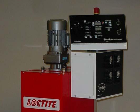
4 1 BACKGROUND This 5-Gallon PUR Product Pail Unloader is designed to extrude Henkel or other PUR products. This equipment has been designed for ease of use and longevity. Its unique pail elevator design permits extrusion of the adhesive product without flexing of hoses or cable bundles. In addition, a number of safety devices are built-in to protect the operator during use of the equipment. Further, the unit s small footprint and easy to use iconic control panel makes it an ideal solution to PUR dispense applications. It is highly recommended that the system be kept sealed as much as possible. PUR product is a moisture cure sensitive material, and is best to keep its exposure to air at a minimum. Once a pail is loaded, do not remove it until another is available for replacement or a system purge is required. The product path is from the pail through the heated platen to the hose and to the applicator. Keep this product path sealed at all times for prolonged trouble-free operation. 2 PERSONNEL SAFETY Wear the following protection when working on or around this equipment: Always wear heat resistant gloves rated to 205 C (400 F). Then using heat resistant gloves, allow all system temperatures to stabilize at 193 C (380 F) or below before attempting operation or maintenance. Use leather or insulating apron when changing pails or performing maintenance on or around the platen. Always wear eye protection when servicing, operating or dispensing the equipment. Properly ventilate equipment according to appropriate MSDS of the hot melt material used. Do not store combustible materials in the vicinity of equipment. Trained operators may perform only external equipment adjustments. Trained maintenance technicians must perform internal adjustments and service. 3 MACHINE SAFETY This equipment contains potential energy (pneumatic and fluid) that can be dangerous if not properly released prior to maintenance or service operations. 2
5 Prior to any repair, machine modifications or maintenance 1. Close main air supply shut-off valve. 2. Turn main electrical power off, if not troubleshooting electrical problems. When loading or unloading product pails, keep hands and body parts away from pinch points such as: 1. Platen and pail. 2. Elevator and machine panels. 3. Machine access door. 4 LIST OF ASSEMBLIES SUPPLIED (1) 5-Gallon PUR Pail Unloader (1) Electrical power cord (un-terminated) (1) Equipment manual 5 DESCRIPTION 5.1 Theory of Operation The 5-Gallon PUR Pail Unloader is designed to extrude PUR product from metal straight-sided containers. A pail is prepared for loading onto the unloader. The access door is opened in order to install a pail of product. The pail is positioned onto the elevator platform and the platen is engaged onto the pail. A heated platen melts the product which then flows towards the center of the platen (by design). As the elevator maintains pressure on the pail, the 3
6 liquefied product is channeled towards the gear pump around the bottom center of the platen. On the control panel, a temperature range is selected that is within the products temperature use. Once the application temperature is reached, the equipment is ready to dispense product. When the applicator trigger is actuated, the gear pump turns on and forces the product down the heated hose and towards the dispense applicator. 5.2 Main Components Control Panel Control and trouble shooting for the entire melt system is accomplished from the melt unit controller front panel. A brief overview of these controls and indicators follow. STANDBY CONTROL PUMP SPEED CONTROL PAIL PURGE/BLOW-OFF ELEVATOR CONTROL TEMP LOOP CONTROL ELEVATOR FUNCTION PUMP CONTROL TEMP RANGE Elevator Control Up (motion) Continuous; solid line Up (motion) Pulse; dashed line Down (motion) Continuous; solid line Down (motion) Pulse; dashed line To make the elevator move, place the Elevator Control selector switch as desired, then press the Elevator function pushbutton Temp Control Purge/Blow-Off Elevator Function Sets Temp Range; temperatures of Platen, Hose, and Applicator Removes air from pail during loading (elevator selector in up position); Injects air into the empty pail for removal (elevator selector in down position). Actuates the ELEVATOR CONTROL function selected 4
7 Pump Speed In increments of 2% (each bar represents 10%) Temp Range Current range selected Pump Control Turns On/Off the Pump Standby Control Places process temperatures set points 40% below nominal for a preset (programmable) time Temperature Range The temperature range indicator is a single 7 segment LED display showing the range currently set for the tank, hose, and head temperatures. A chart indicating the settings for each temperature range is listed as follows: Deg. F (Deg. C) Tank Temperatures Hose and Head Temperatures Range to 195 ºF (49 to 91 ºC) 150 to 225 ºF (66 to 107 ºC) Range to 235 ºF (71 to 113 ºC) 190 to 265 ºF (88 to 129 ºC) Range to 275 ºF (93 to 135 ºC) 230 to 305 ºF (116 to 152 ºC) Range to 315 ºF (116 to 157 ºC) 270 to 345 ºF (132 to 174 ºC) Range to 355 ºF (138 to 179 ºC) 310 to 385 ºF (154 to 196 ºC) Range to 395 ºF (160 to 202 ºC) 350 to 425 ºF (177 to 218 ºC) See section for programming instructions Most manufacturers of hot melt adhesives offer advice for setting the temperatures of the delivery system. In order to reduce degradation of the adhesive, the delivery hose should be at a lower temperature than the applicator and melting tank (or platen) at a lower temperature than the delivery hose. When volume requirements vary, the temperature settings for the melting tank and delivery hose may also vary. The applicator will always be set to the recommended delivery temperature, however certain conditions may require adjustment of this setting. For the purpose of the following example however, we will assume that conditions are ideal. In this example, the adhesive will have a recommended delivery temperature of 350 F. Volume Low Medium High Requirement: Platen Setting Hose Setting Applicator Setting
8 Zone Heating Indicator The series of Loop Output indicators refer to the platen, hose, and head. The LED s will flash amber while warming up. Once the desired temperature has been reached, each LED Loop Indicator output will turn to a green color. Note that all three LED s should be a flashing green color before dispensing adhesive Melt Unit Ready Lamps When the Melt Unit is ready to operate, all three LED indicators as observed on the Loop Output Indicator row of LED s will flash green. Note that the pump will not operate until the Pump Platen is at temperature. The pump platen is at temperature when the associated LED is flashing GREEN. The pump WILL operate even if the HOSE or HEAD is NOT at temperature. It is therefore recommended that adhesive only be dispensed after all of the LED s have changed from a flashing AMBER color to a flashing GREEN color Temperature Setting to Fahrenheit or Celsius o o o Use the Loop Select Up/Down button to select Platen. The LED to the left of the device should show green. Press the Loop Select button four times. The Range indicator will start to blink. Pressing the Loop Select button will toggle the display from degrees C and F and vice-versa Temperature Loop Control It will be necessary to turn ON the accessories that are connected to the platen (hoses & applicators). By using the up/down arrow buttons until the LED is on the device that will be used, for example: Hose 1 and Valve 1. By depressing the On/Off button the LED on the output side will illuminate. In similar manner, the devices that are no longer required can be turned off. When the temperature range is selected ( ), these devices will be supplied power to heat-up. LOOP ON/OFF CONTROL PUMP CONTROL The Platen does not require to be turned ON this is an automatic function. 6
9 Pump Control The pump is typically turned on (Cycle) from Idle automatically when a dispense applicator is triggered (on). Use the On/Off button to turn the Pump on or off manually. On occasion, material may have to be purged without the use of an applicator at the end of a hose. By manually turning this function ON, the pump will come on and allow material to flow (without using an applicator) Standby Control This function is useful on occasions when the machine users have to take an extended time away from the machine, such as a lunch break. Placing the machine in standby automatically lowers all set-point temperatures by approximately 40% from nominal. The lowered temperatures stay at this new setting for a pre-programmed time. After the time expires, the Set-point temperatures go back to the (original) process temperatures. To enter standby mode, just press the STBY button on the control panel as shown in section Use the Set-Temp Increment/Decrement arrows to adjust how long (time) the standby mode is supposed to last (be active). If this function is used during a lunch break, for example, program the STBY time to end about 10 to 15 minutes earlier than the lunch break will last. In this manner, the machine will be up to temperature by the time the user is back from lunch Open Sensor LED (Safety feature) This LED will be illuminated RED in color when an open circuit condition is sensed. It could happen due to a faulty applicator, a main melt unit malfunction, or even a hose that has failed. The affected zone is automatically de-energized and the green LED loop indicator for that zone ceases to function. This provides a very accurate, simple, and fast turn-around time when there is a system problem. For example, if the failure occurred in the HEAD area, a new applicator could easily be replaced, and you would be back in business, up and running! Auxiliary Input Connection One auxiliary connection is available for each hose/applicator employed in the system. Different examples of an auxiliary device might be: foot switches, a timer or pattern controller, which would allow you to apply adhesive in different patterns and pressures (such as a swirl pattern when using a swirl tip) Pump Platen Temperature The pump platen is the first temperature that you would want to select. The pump platen temperature can be independently set using the following procedure: 7
10 a. Select the platen as the device you wish to set. This is accomplished by pressing the Loop Select Up arrow button until the green LED to the left of the Platen label is illuminated. LOOP SELECT UP LOOP SELECT DOWN b. Rapidly press the Loop Select Up button four times. This will change the Range Indicator Digit from a solid state to a blinking state. c. Using either the Set Temp Increment or the Set Temp Decrement button will either increment or decrement the Range Indicator Digit. d. After the Range Indicator Digit has been incremented/decremented, you can now use the Set Temp Increment/Decrement buttons to change the desired temperature. If the Range that you selected in the first part of this procedure is not the range that you desire, you must repeat step #1 until you are at the range you want. SET TEMP INCREMENT/ DECREMENT Hose 1 & 2 Temperature 1. Select Hose 1(2) as the device you wish to set. This is accomplished by either pressing the Loop Select Up or the Loop Select Down buttons until the green LED to the left of the HOSE 1(2) label is illuminated. 2. Use either the Set Temp Increment or Set Temp Decrement buttons to increment/decrement the desired temperature. 8
11 Head 1 & 2 Temperature 1. Select Head 1(2) as the device you wish to set. This is accomplished by either pressing the Loop Select Up or the Loop Select Down buttons until the green LED to the left of the HEAD 1(2) label is illuminated. 2. Use either the Set Temp Increment or Set Temp Decrement buttons to increment/decrement the desired temperature Pneumatic Control Panel Below the Main Control Panel are 4 air pressure regulators that are required for the PUR Unloader to operate properly. Review the illustration below to familiarize yourself with the location of these regulators. ELEVATOR UP ELEVATOR DOWN BLOW-OFF PLATEN SEAL Elevator Up Elevator Down Platen Seal Blow-Off Adjust the rate of rise of the elevator Adjust the rate of descend of the elevator Air pressure to platen s (pail) seal Pressure used to blow air into an empty pail during removal DO NOT exceed 15 PSI on the Platen Seal or damaged to the seal assembly may result Platen Review the call-outs below and become familiar with the platen and associated components and hardware. 9
.")
12 SEAL AIR LINE FRAME TIE RODS (3) BLOW-OFF AIR LINE HEATED HOSE DRIVE MOTOR SHAFT PLATEN HEATER WIRES CONDUIT Silicon Seal This seal is an integral part of this system. The seal will automatically inflate when a new pail is loaded (and elevator control is up and the elevator function pushbutton has been actuated). Once the elevator is raised, the seal inflates and creates a seal; preventing moisture from getting into the pail (or the product from getting out of the pail). When the pail is empty of product and the elevator is cycled down, the seal will automatically deflate to allow the pail to move down and thus be removed. PLATEN SEAL The seal only operates with the actuate function pushbuttons (elevator up/down). It will not deflate (if inflated) and the power is turned OFF Product Pressure Regulator The regulator is used to adjust for product pressure. Increasing the pressure will increase the delivery force of the product. 10
13 Use the motor speed in conjunction with the pressure regulator to achieve a balance between product output volume and pressure of the product coming out of the nozzle. PUMP PRESSURE REGULATOR Particle Filter The particle filter is designed to capture solids and keep them from getting into the gear pump assembly and subsequently into the product path. Be sure to have the system in a maintenance mode before removing the filter. The filter is easily removed with a wrench. The filter can then be replaced with a new one or cleaned and re-installed. When the machine is powered for the first time, inspect the filter after 30 days. Based on the filters condition at the time, devise and schedule an interval maintenance inspection. PARTICLE FILTER Pail Elevator The elevator is powered by an 18 pneumatic cylinder capable of developing up to 5,000 pounds of force. However only minimum air consumption is needed to cycle the elevator. In the event of a power failure, the elevator will be locked into position by a series of 3- way pneumatic valves Gear Motor Control The Gear Motor is brush-less and the speed is fully variable. The motor can be adjusted from 6 Hz to 90 Hz; or from 10 to 150% of the nominal (60Hz) frequency. The Pump Pressure Indicator (with up/down arrows) on the control panel provides this adjustment. 11
14 Each time the button is depressed (lets say up) the frequency increases by 2Hz. With 10 depressions, 1 LED indicator will illuminate. The same goes for decreasing the motor speed. By changing the speed of the motor, more or less product volume can be delivered in the same amount of time. It is best to run the machine at an optimum pressure. Do not run the motor faster than it has to for the particular application. Perform trials into a waste bucket until the best delivery results are obtained. Other factors that influence product output is the temperature of the product (viscosity), pump pressure, hose length, and the nozzle tip. VARIABLE SPEED MOTOR PUMP SPEED CONTROL 12
15 6 TECHNICAL DATA 6.1 Specifications Data Components Platen Gear Motor Pump 2300 Watts/with baked on Teflon coating, silicon inflatable seal ½ hp, 10 to 150% frequency variable Flow rate 197 lb/hr Weight 375 lbs Dimensions 6.2 Energy Requirements Electrical 30W x 22D x 52 ¼H Supply Voltage Amperage 220 VAC, 1 Phase 30 Amp maximum Pneumatic Air Supply / Pneumatic Quality PSI Filtered 1 μm, oil free, non-condensing Connections Inlet Pneumatic Electrical 1/4 tube quick disconnect single-phase power wires 7 INSTALLATION 7.1 Floor Space Requirements Allow for machine size plus hose length. In addition, consider overhead space in the event the process may be more favorable to a hose hanging over the work area rather than having the hose lying on the floor. 13
16 7.2 Assembly A. The machine comes fully assembled. It should be necessary only to remove from the crate and position on the floor space allocated. B. Mount a handle for the dispense applicator to be held when not in use. This will provide a safe location for the applicator when it is HOT. 7.3 Connections An electrical power drop off into the Main Control Panel is required. Single phase power, 220 volts AC, 30 amps. There is one pneumatic (inlet) connection required. The air source port is a female ¼ tube quick disconnect fitting. Connect an air source of 80 PSI, dry, filtered air. 8 OPERATIONS Observe caution when operating the machine. Wear proper safety equipment when handling adhesive product. 8.1 Powering Up the PUR Unloader Ensure that the main circuit breakers are ON. Turn the main power switch to ON. The display indicators on the Control Panel will illuminate. All functions STOP if the pail load/unload access door is open (the control panel will illuminate) Daily Start-up A. Ensure all utilities are connected and available. B. Set (inlet) pneumatic pressure to 80 PSI. Turn on the air supply to the station. C. On the side of the Control Panel, turn the rotary ON/OFF power switch. 14
17 8.2 Recovering from an E-Stop Once an E-Stop occurs, all machine motion stops. Ensure that it is safe to resume dispense operations and then un-twist the E-stop knob. If power has been off for some time, it will be necessary to wait until the process temperatures are reached before beginning a dispense operation. 8.3 Loading a Pail Wear proper safety gear when installing or removing pails from the machine. Use only metal straight-sided pails with no ribs. Once a pail is loaded DO NOT remove it until there is a new pail to immediately replace it or purge material available for a system purge. Try to maintain the system sealed from moisture at all times. A. Remove the lid from the pail. WARNING When raising or lowering the elevator, keep hands and body away from the platen and pail lip. B. Open the access door on the machine and position the pail against the 2 stops on the elevator platform. Close the door; safety switch on door must be closed. C. Adjust the temperatures on the Control Panel as required for the material. D. Place the Elevator Control selector knob to Up and Pulse. Press and release in small increments the Up/Down Elevator Function pushbutton until the pail makes contact with the platen. Look through the top of the access door. As the pail gets closer to the platen, if you notice that the edge of the pail and the platen are not aligned, open the access door or lower the elevator and adjust the centering stops on the elevator platform. E. Place the Elevator Control selector knob to UP and Continuous, and then press the Elevator Function Up/Down button once. Simultaneously, press the PURGE 15
18 pushbutton to evacuate air from the pail as the elevator moves up. The elevator will ascend continuously and stop ascending once it comes into contact with the product in the pail. The platen seal will then inflate to seal the pail. F. Wait until the temperatures are reached for all dispense components before beginning a dispense. G. Adjust the pressure regulator and Gear motor speed if required. 8.4 Purging Purging is required (typically) when a new pail is loaded. Purging removes any air that may have become trapped in the product path. It is most important that all air is removed from the material or it may dispense irregularities and cause internal product curing. The Purge function will only work when the elevator position selector is in the UP position. A. During the Pail Loading procedure press the Purge/Blow-Off pushbutton on the top right corner of the control panel. This will actuate a valve and allow air to be released from the top of the pail as it nears the product in the pail. B. Most of the air from loading the pail should be removed during pail loading and using the Purge pushbutton. If the previous pail was emptied and air bursts were observed at the applicator then: hold the dispense applicator over an empty pail (to capture waste). C. Use the trigger on the applicator until a continuous stream of product is coming out without any burping or voids. This will remove the remaining air from the product path. 8.5 Removing an Empty Pail Wear proper safety gear when installing or removing pails from the machine. DO NOT remove a pail until there is a new pail readily available for loading. DO NOT open the pail access door until the elevator has come completely down. A. Place the Elevator Control selector knob to the Pulse Down position. B. Press and pulse the Elevator Up/Down pushbutton while pulsing the Blow-Off pushbutton until the pail is lowered completely and is not in contact with the platen. The platen seal will deflate automatically. C. If the pail does not lower when the elevator goes down 16
19 a. Ensure that the elevator is not too far from the bottom of the pail. Raise the elevator again if required and keep the pail within 2 to 3 inches from the elevator platform (in the event the pail suddenly drops, it will not be a violent fall). b. Slowly increase the pressure to the Blow-OFF valve; this will blow air into the pail to separate the pail from the platen. c. If necessary, with the elevator down, try to tilt slightly and rotate the pail to break the capillary seal with the platen. 8.6 Dispensing Hand Held Applicator A. Most applications will use a manual applicator. This device has a pump start switch opposite the trigger switch, which needs to be actuated for dispensing. B. Press and hold the applicator s trigger switch for dispensing to take place. Release the trigger to stop the adhesive flow. When starting the machine for the first time each day, it is a good idea to dispense into a waste cup to check that the dispense setup (volume/pressure) is what is desired. Make adjustments if necessary see sections and Automatic Valve A. These valve types are fixed mounted valves for automatic dispensing. The valves are available with electrical control and can be triggered with a footswitch, or can be integrated to a customer control system for remote triggering. B. A pneumatic version of the automatic valve is also available for applications that require fast cycle times; yet, typically have lower viscosities. 8.7 Shutting the System Down The nature of the PUR material is such that it necessitates that the system (material path) be kept seal at all times. Whether overnight, weekend or extended shutdown, it is best to leave the system be as it is. The machine should power up as usual with no expected dispense problems so long as the system has remained sealed. The one area that could experience a problem (most likely due to clogging) is the dispense nozzle. Harden material at the nozzle tip can be removed with a small pick or small drill bit. Care should be observed not to enlarge the nozzle hole size when clearing the clog. 17
20 In event that the machine does not dispense after a start-up, see the Trouble-shooting section of this manual or refer to section MAINTENANCE 9.1 Control Panel The control panel should be kept free of dirt and adhesive in order to provide clear, workable and visible panel indicators and functional buttons. 9.2 Elevator Linear Rails The rails are lubricated for life and require no maintenance. Though it is a good practice to inspect for security, or product splatter build-up (4 month interval to start). Do not allow the machine to operate with a loose rail. 18
21 9.2.2 Elevator Platform Maintain the area where the pail is located clean and free of product. If product hardens and builds gradually here, installing and keeping level new pail loads may become difficult to accomplish. 9.3 Product Delivery Path Platen DO NOT allow the machine to remain off with PUR material on the platen sitting idle for weeks without use. If it is expected that the machine will be shut down for longer than 2 weeks; purge the machine with purge/cleaning product before the shut down. DO NOT attempt to clean the bottom of the platen. The best course is to try to maintain the platen sealed (with a pail) once it has been exposed to PUR material. DO clean spills on top of the platen immediately to keep the surface clean and serviceable. The surface is baked on Teflon and should make clean-ups easier; but do not allow PUR material to sit too long on the platen Silicon Seal The seal is designed for many hours of trouble-free operation. If used properly, the seal is expected to last for the life of the platen. Clean or peel material on the seal immediately to prevent build-up and maintain a good seal Hoses Inspect hoses for fraying and damaged weekly. Hoses can easily become damaged if they are on the floor in a high foot-traffic area. Keep a clear work area for the hose to prevent damage. The following points should be kept in mind concerning hot melt supply hoses: The hose should not be flexed when cold to avoid damage. The hoses have a minimum bend diameter of sixteen inches when hot, further flexure will cause permanent damage. Hot melt fittings must be heated before loosening or tightening to prevent damage. New and clean supply hose fittings do not need to be heated. Support the hose during gluing operations to prevent excessive flexure. Failure to properly support the hose will result in premature failure. 19
22 9.3.4 Applicator Dispense Nozzle The handgun nozzle should never be pointed towards people when the melt unit is powered. Pressures can develop within the hot melt system causing the glue to be projected significant distances. Pointing the handgun at someone (including yourself!) presents a potential burn hazard. The trigger mechanism of the handgun should never be pulled until the entire system is up to operating temperature. Attempts to retract the trigger before glue in the handgun has adequately softened will result in damage to the needle assembly. This damage is not covered under warranty. The backside of the handgun grip contains a yellow lever to control pump motor operation. It is recommended that the front panel of the melt unit be set for idle operation with pump motor control from the handgun switch. This will prevent unnecessary wear on the motor and pump mechanisms. Hot melt fittings must be heated before loosening or tightening to prevent damage. New and clean supply hose fittings do not need to be heated. During normal use, the nozzle should not require maintenance. If the system is shut down for extended periods of time, the tip of the nozzle may become clogged. The best way to clear the nozzle from cured material is using a small pick. In some instances it may be necessary to use a small or fine drill bit to clear the tip Connections There are a number of connections that should be inspected for security and damaged at least weekly. The inspection schedule can be adjusted once a history of the machine s performance is well established. Inspect the aluminum pneumatic lines that attach to the platen for kinks or leaks. Inspect the Gear motor couplings (top and bottom). Inspect the hose connection at the platen. Ensure the security of the (3) tie rods from the platen to the top frame mounts Pressure Regulator This component does not require regular maintenance; though it is a good idea to keep the adjustment knob clean and free of product waste so that it remains serviceable. 20
23 9.4 Troubleshooting Table PROBLEM PROBABLE CAUSE SOLUTION Adhesive does not come out of the Clogged tip Use a small pic to remove cured nozzle material at the tip A small drill bit can be used to clear the nozzle tip as an alternative. Unit does not reach temperature Adhesive not molten Loose connector Failed heater element Wait for proper temperature to be reached. Check the Control Panel for a RED indicator of a failed element. Tighten the connector or replaced the failed component. Not enough or too much material is coming out of the applicator Low or high pump regulator pressure Gear motor is not turning at the proper speed. Adjust the regulator pressure as required. Adjust the speed using the Main Control Panel. Elevator does not move Platen seal is not inflating Power does not stay the machine Dispensing faster than the unit can melt the material. Air source Elevator air regulator Door interlock safety switch is open Insufficient air pressure Elevator selector switch not in Continuous UP position. Interlock switch in main cylinder compartment is not working or needs adjustment. Machine does not have air supply Temperatures exceed allowable range Lower the dispense rate or volume and re-check operation. Check air source to machine. Adjust regulator to proper pressure to move the platform. The door must be closed Adjust the seal regulator Check the position of the selector switch. This switch prevents the seal from inflating before the seal is inside the pail. Ensure that the required air is being sourced to the machine. Over-temperature condition. Allow the machine to cool down and then attempt to power the system again. 21
24 9.5 Components Schematics Handgun Applicator 22
25 9.5.2 Hose and Handgun Electrical 23
26 9.5.3 EG and AG (fixed mount) Applicator 24
27 10 REPLACEMENT PARTS Visit and look in Hot Melt equipment pages, or contact your local Henkel sales representative to request a quote for specific Loctite components. 25
5-Gallon Pail Unloader. Item # EQUIPMENT MANUAL
 5-Gallon Pail Unloader Item # 1012854 EQUIPMENT MANUAL 1 BACKGROUND...2 2 PERSONNEL SAFETY...2 3 MACHINE SAFETY...2 4 LIST OF COMPONENTS SUPPLIED...3 5 DESCRIPTION...3 5.1 THEORY OF OPERATION...3 5.2 MAIN
EQUIPMENT Operation Manual
 EQUIPMENT Operation Manual Loctite Hysol BULK 14 System Part Number 98133, 115VAC Model Part Number 98134, 230VAC Model TABLE OF CONTENTS 1. PLEASE OBSERVE THE FOLLOWING... 4 1.1 Emphasized Sections...
GEMINI TM DYNACONTROL TM HOSES Automatic & Manual Versions FOR DYNAMELT & DYNAMINI TM ADHESIVE APPLICATION SYSTEMS
 ITW Dynatec c. 2006 Page 1 Revised 4/20/07 Description GEMINI TM DYNACONTROL TM HOSES Automatic & Manual Versions FOR DYNAMELT & DYNAMINI TM ADHESIVE APPLICATION SYSTEMS Adhesive supply hoses are electrically-heated,
Setup. Important. Texture Spraying (material supplied from unit)
") Setup Setup Important If you are going to stop spraying for more than 5 minutes, turn sprayer off to prevent shortened pump hose life. Do not allow material to dry inside pump, hoses, gun or spray system.
Setup Setup Important If you are going to stop spraying for more than 5 minutes, turn sprayer off to prevent shortened pump hose life. Do not allow material to dry inside pump, hoses, gun or spray system.
Filabot EX6 Extruder. Operation Manual. CAUTION! Read Carefully. Filabot Vermont, USA, Earth
 Filabot Vermont, USA, Earth 1-802-505-6772 CAUTION! Read Carefully HOT MATERIALS & SURFACES Use gloves and eye protection while operating the EX6 Extruder. The barrel and nozzle are HOT and melted plastic
PWC 1800 PureWaterCooler SERVICE MANUAL. for. PureWaterCooler by Vertex Model PWC P/N man Copyright 2011 Vertex Water Products
 SERVICE MANUAL for by Vertex Model PWC-1800 P/N man-7011 Table of Contents 1. Introduction 2. Cooler Set-up 3. Remove Top Cover 4. Remove/Replace Float 5. Remove/Replace Hot Tank 6. Dispensing Solenoid
Owner s Manual RD432-0 Chemical Controller
 Owner s Manual RD432-0 Chemical Controller Table of Contents I. Introduction page 2 A. Water Chemistry page 2 B. Safety page 3 C. System Components page 4 D. Specifications page 7 E. Controller Panel Descriptions
M770 ph Controller Owner s Manual
 M770 ph Controller Owner s Manual Table of Contents I. Introduction page 2 A. Water Chemistry page 2 B. Safety page 3 C. System Components page 4 D. Specifications page 7 E. Controller Panel Descriptions
Covering Basic Operation for the GMS HM10 Hot Melt Unit (10# Tank)
") GMS Hot Melt Gluing System Operation and Maintenance Manual Covering Basic Operation for the GMS HM10 Hot Melt Unit (10# Tank) GMS INC. 2014 1 GMS INC. 2014 2 TABLE OF CONTENTS HM10 HOT MELT GLUING SYSTEM
GMS Hot Melt Gluing System Operation and Maintenance Manual Covering Basic Operation for the GMS HM10 Hot Melt Unit (10# Tank) GMS INC. 2014 1 GMS INC. 2014 2 TABLE OF CONTENTS HM10 HOT MELT GLUING SYSTEM
HFG 12 and 24 Hydrogen Generators Installation Instructions
 HFG 12 and 24 Hydrogen Generators Installation Instructions Model 12 Model 24 PLEASE READ THESE INSTRUCTIONS FROM BEGINNING TO END BEFORE STARTING YOUR INSTALLATION. If you are still having problems after
Operator: Save these instructions for future use!
 WHITE-RODGERS 1F81-51 Programmable Electronic Digital Multi-stage Thermostat INSTALLATION AND OPERATION INSTRUCTIONS Operator: Save these instructions for future use! FAILURE TO READ AND FOLLOW ALL INSTRUCTIONS
CMU701/ 705 OPERATIONS & INSTRUCTION MANUAL
 CMU701/ 705 OPERATIONS & INSTRUCTION MANUAL MANUFACTURED BY 2519 Fairmont Road Morgantown, West Virginia 26501 PHONE: (304)-983-2642 FAX: (304)-983-2643 www.imswv.com 1 TABLE OF CONTENTS: 1.) Introduction
Introduction... 3 Setup & Suggestions... 4 Basic Use... 4 Setting Time... 4 Setting Temperature... 5 Setting Height / Pressure...
 Table of of Contents Contents... 2 Introduction... 3 Setup & Suggestions... 4 Basic Use... 4 Setting Time... 4 Setting Temperature... 5 Setting Height / Pressure... 6 Aligning the pedestal... 6 Guidelines
P6500W Air Dryer User s Guide
 P6500W Air Dryer User s Guide 1. Welcome & Congratulations Congratulations on your purchase of a new PUREGAS P6500W Air Dryer! We here at PUREGAS are very proud of our products and we are committed to
CAREFULLY READ THESE INSTRUCTIONS BEFORE USING SAFETY PRECAUTIONS USE OF EXTENSION CORDS
 Owner s Manual CR2500ACH CR5000ACH Portable Heating and Air Conditioning Unit Version 02 Table of Contents 1. SAFETY INSTRUCTIONS... 1-1 CAREFULLY READ THESE INSTRUCTIONS BEFORE USING... 1-1 SAFETY PRECAUTIONS...
Axiom Technologies L.L.C Telephone: Pennbright Dr., Suite 220 Fax: XP7 USER S MANUAL
 L.L.C Telephone: 281 931 0907 255 Pennbright Dr., Suite 220 Fax: 281 931 6562 Houston, Texas 77090 www.axiomsafety.com XP7 USER S MANUAL COMPACT MULTI-CHANNEL ALARM & SHUTDOWN SYSTEM GENERAL The XP7 alarm
PWC 7000 PureWaterCooler SERVICE MANUAL. for. PureWaterCooler by Vertex Model Copyright 2012 Vertex Water Products
 SERVICE MANUAL for by Vertex Model 7000 Table of Contents 1. Introduction 2. Cooler Set-up 3. Top Cover Removal 4. Remove/Replace Mechanical Float Valve Assembly 5. Removing/Replacing Control Panel and
8070 Mytee Lite. Instructions for. Please read before use. Register your product at support/register.
 Instructions for 8070 Mytee Lite Please read before use. Register your product at http://www.mytee.com/ support/register Model # Serial # Form # ADP-8070 06-16 1 GENERAL INFORMATION Dear Customer: Congratulations
PRO 2000i LOW LEVEL DEPOSITOR
 DEPOSITORS AND AUTOMATED CAKE PRODUCTION SYSTEMS PRO 2000i LOW LEVEL DEPOSITOR OPERATION AND SPARE PARTS MANUAL Serial No. PR2L- (Please quote this number when ordering spares, and making service calls)
TC-710 RECYCLING BALER
 OPERATING AND MAINTENANCE INSTRUCTIONS TC-710 RECYCLING BALER READ INSTRUCTIONS THOROUGHLY BEFORE OPERATING 3451 S. 40th Street Phoenix, AZ 85040 602.437.5020 800.223.4540 www.tsissg.com info@tsissg.com
ENSPECO Recovery/ Recycle/ Evacuate/ Recharge
 ENSPECO Recovery/ Recycle/ Evacuate/ Recharge RMS 3012 RMS 3034 Approved by UL/SAE to J-1991 R12 Purity Standards Approved by UL/SAE to J-2210 R134 Purity Standards This semi-automatic machine will recover
OPERATION & MAINTENANCE MANUAL TC670
 OPERATION & MAINTENANCE MANUAL TC670 Refrigerant Management Center (Convertible For Use With R12 or R134a) RTI TECHNOLOGIES, INC. 4075 East Market Street York, PA 17402 Manual P/N 035-80342-02 TC670 CONVERTIBLE
PWC-500/1000/1010/1500
 SERVICE MANUAL for by Vertex Model PWC-500/1000/1010/1500 P/N man-7008 Table of Contents 1. Introduction 2. Cooler Set-up 3. Remove Top Cover 4. Remove/Replace Float 5. Remove/Replace Hot Tank 6. Faucet
P4200PM / P5000PM Remote Air Dryer User s Guide
 P4200PM / P5000PM Remote Air Dryer User s Guide 1. Welcome & Congratulations Congratulations on your purchase of a new PUREGAS P4200PM / P5000PM Air Dryer! We here at PUREGAS are very proud of our products
ZD-985 Desoldering Station
 ZD-985 Desoldering Station 2 Contents Contents... 3 Unpacking and Setting Up Your ZD-985 Desoldering Station... 4 Setting Up the Unit... 5 Auto Tip Saver Function... 8 Tips and Techniques... 8 Alloy Melt
INSTANT HOT WATER DISPENSER
 INSTANT HOT WATER DISPENSER Tank Installation Materials required (not provided) 2 mounting bracket screws (and 2 plastic anchors if attaching to drywall) Shut-Off valve and T fitting Components When you
Operator: Save these instructions for future use!
 WHITE-RODGERS 1F82-51 Programmable Electronic Digital Heat Pump Thermostat INSTALLATION AND OPERATION INSTRUCTIONS Operator: Save these instructions for future use! FAILURE TO READ AND FOLLOW ALL INSTRUCTIONS
BEFORE OPERATING THE MACHINE: WARNING
 BEFORE OPERATING THE MACHINE: Read the manual carefully and completely before attempting to operate the unit. This manual has important information for the use and safe operation of the machine. Keep this
5) Do not start or stop the unit by inserting or pulling out the power plug.
 Do not start or stop the unit by inserting or pulling out the power plug.") 3058080 V170306 PURCHASE INFORMATION Thank you for choosing a Soleus Air Portable Air Conditioner. This Owner s Manual will provide you with valuable information necessary for the proper care and maintenance
3058080 V170306 PURCHASE INFORMATION Thank you for choosing a Soleus Air Portable Air Conditioner. This Owner s Manual will provide you with valuable information necessary for the proper care and maintenance
R100 Oil-Less Refrigerant Recovery Unit
 R100 Oil-Less Refrigerant Recovery Unit Operation Manual 1 INTRODUCTION Welcome to simple, efficient refrigerant recovery with your new YELLOW JACKET Refrigerant Recovery Unit, R100. This unit combines
Automatic Hot Melt Gun Model AD-28
 Automatic Hot Melt Gun Model AD-28 Part 6 992A NORDSON CORPORATION AMHERST, OHIO USA 42-4- Nordson CORPORA TION / Amherst, Ohio 44&T/ CONTENTS TECHNICAL PUB /CATION Title Page 42-4-O Contents Page - Description
Installation Instructions. For the 18 Built-In Dishwasher and Front Color Panels
 Installation Instructions For the 18 Built-In Dishwasher and Front Color Panels Printed in USA 154232102 Before You Begin DO NOT INSTALL DISHWASHER UNTIL YOU HAVE READ ALL INSTRUCTIONS. FOR YOUR SAFETY,
TIF9055 Programmable. Owner s Manual Manual del Propietario Manuel du propriétaire Benutzerhandbuch Manuale del proprietario
 TIF9055 Programmable Refrigerant Meter Owner s Manual Manual del Propietario Manuel du propriétaire Benutzerhandbuch Manuale del proprietario TABLE OF CONTENTS 1 General Information 2 Features 3 Controls
OWNER S MANUAL VERSION 4.4 SERIAL # X-1 SINGLE LAYER PRESS. With EG-260 Variable Speed Grinder
 OWNER S MANUAL VERSION 4.4 CONFORMS TO UL STD 763, NSF/ANSI STD 8 CERTIFIED TO CSA STD C22.2 #195 CONFORMS TO CE, IEC TESTED X-1 SINGLE LAYER PRESS With EG-260 Variable Speed Grinder SERIAL # 2 20 INTRODUCTION
OPERATING & SERVICE PARTS MANUAL HDS-215 COMBINATION SHRINK SYSTEM
 OPERATING & SERVICE PARTS MANUAL HDS-215 COMBINATION SHRINK SYSTEM FOR HOT KNIFE AND IMPULSE MACHINES READ ALL INSTRUCTIONS CAREFULLY BEFORE OPERATING EQUIPMENT TABLE OF CONTENTS Electrical Requirements
TABLE OF CONTENTS. NOTE: Read the entire instruction manual before starting the installation. TROUBLESHOOTING... 13
 R 410A Duct Free Split System Air Conditioner and Heat Pump Product Family: DFS4(A/H) System, DFC4(A/H)3 Outdoor, DFF4(A/H)H Indoor NOTE: Read the entire instruction manual before starting the installation.
Non-RTD Hot Melt Hose Replacement
 Instruction Sheet P/N 7C 0 Safety WARNING: System pressurized! Relieve system hydraulic pressure before breaking any hydraulic connection or seal. Failure to relieve the system hydraulic pressure can result
General System Layout Sketch
 General System Layout Sketch EZ-37 Solar Panels PV panel Glycol Fill Valve Expansion Tank ` 1 Introduction This document describes how to install a Heliatos GH type solar water heating system. These systems
MF90 Series Portable Filters (CE)
") "U" & "AU" CONFIGURATIONS CE ONLY MF90 Series Portable Filters (CE) Operation, Service & Parts Manual MF90-110 Dean, a member of the Commercial Food Equipment Service Association, recommends using CFESA
"U" & "AU" CONFIGURATIONS CE ONLY MF90 Series Portable Filters (CE) Operation, Service & Parts Manual MF90-110 Dean, a member of the Commercial Food Equipment Service Association, recommends using CFESA
HOKKIM INTEGRATED AMF CONTROL BOARD MANUAL FOR MODELS: HAMF-8 AND HAMF-4
 HOKKIM INTEGRATED AMF CONTROL BOARD MANUAL FOR MODELS: HAMF-8 AND HAMF-4 INTRODUCTION Thank you for purchasing the Hokkim Integrated Automatic Mains Failure Control Board model HAMF- 8 or HAMF-4. We shall
INSTALLATION INSTRUCTIONS UNDERCOUNTER DISHWASHERS
 INSTALLATION INSTRUCTIONS UNDERCOUNTER DISHWASHERS VIKING 111 Front Street Greenwood, Mississippi 38930 USA (662) 455-1200 IMPORTANT - PLEASE READ AND FOLLOW Before beginning - please read these instructions
CAREFULLY READ THESE INSTRUCTIONS BEFORE USING SAFETY PRECAUTIONS USE OF EXTENSION CORDS
 Owner s Manual CR2500ACH CR5000ACH Portable Heating and Air Conditioning Unit Version 01 Table of Contents 1. SAFETY INSTRUCTIONS... 1-1 CAREFULLY READ THESE INSTRUCTIONS BEFORE USING... 1-1 SAFETY PRECAUTIONS...
ELECTRIC DRILL INSTRUCTIONS. Item #21285
 ELECTRIC DRILL INSTRUCTIONS Item #21285 The EASTWOOD ELECTRIC DRILL is great for use on virtually all metals including steel, aluminum, brass and more. The powerful 6.3 Amp motor and 1/2 capacity chuck
Full Size Canister Service Manual Riccar Models 1700 / 1800 Power Nozzles RPB-100 / RPB-220 / RPB-224 / RPB-250
 Full Size Canister Service Manual Riccar Models 1700 / 1800 Power Nozzles RPB-100 / RPB-220 / RPB-224 / RPB-250 Table of Contents I. General Full Size Canister Issues...2 A. Full Bag Indicator...2 1. General
This Manual is prepared for the use of trained Vulcan Service Technicians and should not be used by those not properly qualified.
 SERVICE MANUAL ERA & EBD SERIES ELECTRIC FRYERS WITH KLEENSCREEN PLUS FILTRATION SYSTEMS 2ER50AF KLEENSCREEN FRYER BATTERY MODEL ML MODEL ML 1ER50A 136730 2XER50AF 136747 1E50BD 136730 2XE50BDF 136747
General Characteristics.3. S.M.A.R.T System Set-up...5. Start-up Procedures.6. Shut-down Procedures 8. General Maintenance..8
 1-800-661-3842 1 TABLE OF CONTENTS General Characteristics.3 How the S.M.A.R.T System Works..3 S.M.A.R.T Technical Specifications..3 Erecting the S.M.A.R.T System..4 S.M.A.R.T System Set-up...5 Start-up
K 2.97 M. Specifications Operating pressure, max PSI Water volume GPM Voltage V Amp draw AMPS
 K 2.97 M High Pressure Washer Operator Manual Overview... 2 Important Precautions... 3-4 Assembly Instructions... 4 Operating Instructions... 5 GFCI Instructions... 6 Using the Accessories... 6 Working
Model K 520 M Part No
 Model K 520 M Part No. 1.069-680.0 High Pressure Washer Operator Manual Overview... 2 Precautions... 2-4 Assembly Instructions... 4 Operating Instructions... 5 Using the Accessories... 6 Working with Detergents...
K 3.97 M. Specifications or visit our website: In USA call: Part No
 K 3.97 M High Pressure Washer Operator Manual Overview... 2 Precautions... 2-4 Assembly Instructions... 4-5 Operating Instructions... 5-6 GFCI Instructions... 6 Using the Accessories... 6 Working with
Autotrol Performa FA Valve
 Autotrol Performa FA Valve With 400 Series Control Water Conditioning Control System Dealer Installation, Operation, and Maintenance Manual Table of Contents Installation................................
M790 ph/orp Controller. Owner s Manual
 M790 ph/orp Controller Owner s Manual Table of Contents I. Introduction page 2 A. Water Chemistry page 2 B. Safety page 3 C. System Components page 4 D. Specifications page 7 E. Controller Panel Descriptions
Desoldering Tool. Instruction Manual
 Desoldering Tool Instruction Manual Thank you for purchasing the Hakko 472D desoldering tool with digital temperature display. Please read this manual before operating the Hakko 472D. Keep this manual
P10KW / P15KW Air Dryer Installation Guide
 P10KW / P15KW Air Dryer Installation Guide This guide covers basic air dryer installation and setup only. Once installation is complete, please refer to the P10KW / P15KW User s Guide for more advanced
OWNER S MANUAL COMMERCIAL COLD PRESS JUICER
 COMMERCIAL COLD PRESS JUICER REV.3 Introduction WARNING: To limit risk of personal injury and material damage, all users must read these instructions in their entirety and follow them strictly. MACHINE
OPERATIONS AND MAINTENANCE MANUAL FOR THE 8-TON TURF CART ENVIRONMENTAL CONTROL UNIT (ECU) PART NUMBER
 PART NUMBER") OPERATIONS AND MAINTENANCE MANUAL FOR THE 8-TON TURF CART ENVIRONMENTAL CONTROL UNIT (ECU) PART NUMBER 2001927 Prepared by: 860 Douglas Way PO Box 530 Natural Bridge Station, VA 24579 1 1.0 SCOPE: This
OPERATIONS AND MAINTENANCE MANUAL FOR THE 8-TON TURF CART ENVIRONMENTAL CONTROL UNIT (ECU) PART NUMBER 2001927 Prepared by: 860 Douglas Way PO Box 530 Natural Bridge Station, VA 24579 1 1.0 SCOPE: This
O PE R AT I ON HO851G REVOLVING TRAY OVEN. MODEL HO851G GAS ML Pan ML Pan ML Pan ML Pan
 O PE R AT I ON HO851G REVOLVING TRAY OVEN MODEL HO851G GAS ML-132160 24 Pan ML-132161 18 Pan ML-132258 36 Pan ML-132259 30 Pan 701 S. RIDGE AVENUE TROY, OHIO 45374-0001 937-332-3000 www.hobartcorp.com
Page 1 of 18. Part# /5/2013
 Part# 1002655-06 8/5/2013 This manual contains important information concerning the installation and operation of the gun washers listed above. Read manual thoroughly and keep for future reference INSTRUCTIONS
Portable Air Conditioner 6,000 BTU 8,000 BTU 10,000 BTU
 Portable Air Conditioner 6,000 BTU 8,000 BTU 10,000 BTU OPERATING INSTRUCTIONS PCR-06-01 PCR-08-01 PCR-10-01 3058080 V170223 PURCHASE INFORMATION Thank you for choosing a Chigo Portable Air Conditioner.
K 2.90 M. Specifications Operating pressure, max PSI Water volume GPM Voltage V Amp draw AMPS
 K 2.90 M High Pressure Washer Operator Manual Overview... 2 Important Precautions... 3-4 Assembly Instructions... 4 Operating Instructions... 5 GFCI Instructions... 6 Using the Accessories... 6 Working
HW-17 Record Cleaning Machine Setup and Instruction Manual
 HW-17 Record Cleaning Machine Setup and Instruction Manual VPI Industries, Inc., 77 Cliffwood Ave. #3B, Cliffwood, NJ 07721 Phone: 732-583-6895, Email: Sales@vpiindustries.com http://www.vpiindustries.com
TECHNICAL INFORMATION T1500 Series Clothes Dryers
 TECHNICAL INFORMATION T1500 Series Clothes Dryers 2003 Miele - Table of Contents 1.0 CONSTRUCTION & DESIGN 1.1 Appliance Overview - Vented 1 1.2 Appliance Overview Condenser Models 2 1.3 Controls Overview
OPERATION AND INSTRUCTION MANUAL NORCLEAN POWERED EDDY CURRENT VACUUM RECOVERY SYSTEM WITH WATER TRAP OPTION
 OPERATION AND INSTRUCTION MANUAL NORCLEAN POWERED EDDY CURRENT VACUUM RECOVERY SYSTEM WITH WATER TRAP OPTION THIS SYSTEM IS TO BE USED FOR REMOVING CONTAMINATED DEBRIS FROM EDDY CURRENT PROBES DURING STEAM
Refrigerant Recovery Machine. Model No Operating Manual
 Refrigerant Recovery Machine Model No. 25700 Operating Manual Safety Precautions WARNING : TO PREVENT PERSONAL INJURY AND / OR EQUIPMENT DAMAGE, CAUTION - Risk of injury. This equipment should only be
INSTALLATION and OPERATION BALL WASHER MODEL NO: BW-022
 Easy Picker Golf Products, Inc. 415 Leonard Blvd. N., Lehigh Acres, FL 33971 PH: 239-368-6600 FAX: 239-369-1579 Service: 800-982-4653 SALES: 800-641-4653 www.easypicker.com salesdept@easypicker.com INSTALLATION
Product Identification
 Operation Manual Toaster Grills Product Identification The Prince Castle 47-ACC & 48-BCC Toaster Grill Series offers two practical options for quick-and-easy bread product toasting. Both models have pivoting
XPS-ProDry User s Guide Dryer Base
 XPS-ProDry User s Guide XPS-ProDry User s Guide Dryer Base For Use with Inkjet Imaging Systems Manual Part#: M-3120 Revision: August 2005 XPS-ProDry User s Guide Written by Frank Mauri & John Brand Published
ENVIRO-PAK. Operation and Maintenance Manual. Manufacturer of
 ENVIRO-PAK H Series Single Chamber Compactor Operation and Maintenance Manual Manufacturer of ENVIRO-PAK SAFESUB WINDCHILLER 800-737-5533 WWW.ENVIRO-PAK.NET SALES@ENVIRO-PAK.NET 4308 West Admiral Doyle
Easy-Lam School Budget Roll Laminator
 DO NOT DISCARD BOX! (If for any reason you need to ship your machine back and you discard your box you will be responsible for purchasing another one plus any freight charges to ship the box to you) Easy-Lam
DEMA SOLID PRODUCT LAUNDRY MASTER TM MODEL: 581L-1W and 581L-2W INSTALLATION INSTRUCTIONS
 Included Parts: A. 581.1 Solid Bowl B. 58.1LA Vacuum Breaker C. 58.6 Stainless Steel Supply Tube D. 58.29 90º Compression Fitting E. 58.24 Straight Compression Fitting F. 58.7 Vinyl Discharge Tube G. 66.123
SERVICE MANUAL VC3ED FULL SIZE ELECTRIC CONVECTION OVEN - NOTICE -
 SERVICE MANUAL VC3ED FULL SIZE ELECTRIC CONVECTION OVEN VC3ED ML-137013 - NOTICE - This Manual is prepared for the use of trained Vulcan Service Technicians and should not be used by those not properly
HEATLESS DESICCANT AIR DRYER INSTRUCTION & MAINTENANCE MANUAL
 HEATLESS DESICCANT AIR DRYER INSTRUCTION & MAINTENANCE MANUAL H-Series & 203 THRU 223 SERIES ARROW PNEUMATICS, INC. REGENERATIVE DRYER DIVISION 2111 WEST 21ST STREET BROADVIEW, IL 60155 708-343-9595 708-343-1907
GARAGE HEATER WITH REMOTE INSTRUCTION MANUAL MODEL: HA24-100E HA24-150E. Figure 1
 GARAGE HEATER WITH REMOTE INSTRUCTION MANUAL MODEL: HA24-100E HA24-150E Figure 1 PET OWNERS WARNING: Health warning for some small pets, including birds, as they are extremely sensitive to the fumes produced
Operator: Save these instructions for future use!
 WHITE-RODGERS 1F83-51 Non-Programmable Electronic Digital Multi-Stage Thermostat INSTALLATION AND OPERATION INSTRUCTIONS Operator: Save these instructions for future use! FAILURE TO READ AND FOLLOW ALL
Operation Manual. Equipment. Operation Manual. Loctite EQ PU20 Digital Peristaltic Dispenser. Part Number:
 Operation Manual Equipment Operation Manual Loctite EQ PU20 Digital Peristaltic Dispenser Part Number: 2265279 Operation Manual Table of Contents 1 Please Observe the Following...3 1.1 Emphasized Sections...3
USER MANUAL. Portable Air Conditioner and Heater With Heat Pump Technology PAC18. Please read this manual carefully prior to operating the product.
 USER MANUAL Portable Air Conditioner and Heater With Heat Pump Technology PAC12 PAC15 PAC18 Please read this manual carefully prior to operating the product. TABLE OF CONTENTS INTRODUCTION... 3 IMPORTANT
Dynaflex Hot melt hoses
 ITW Dynatec GmbH Industriestraße 28 D- 40822 Mettmann phone 0049 (0)2104 915 0 fax 0049 (0)2104 915 111 Dynaflex Hot melt hoses IMPORTANT! - READ ALL INSTRUCTIONS BEFORE OPERATING THIS EQUIPMENT It is
HEATING AND VENTILATION
 SECTION 14-102.04 14-102.04/ 1 2007OC19 DESCRIPTION The heating, ventilation and air conditioning (HVAC) system is designed to optimize passenger comfort. The system regulates interior vehicle atmosphere,
OPERATING INSTRUCTIONS FUSION MODEL 610 DIGITAL DISPENSING SYSTEM
 OPERATING INSTRUCTIONS FUSION MODEL 610 DIGITAL DISPENSING SYSTEM 1 FUSION, INC. MODEL 610 PRECISION DISPENSER The Model 610 Dispenser consists of: (1) Dispenser Control Box (2) Foot Pedal Switch (3) Power
MODEL A18 SOLVENT RECOVERY SYSTEMS (EXPLOSION PROOF UNITS)
") MODEL A18 SOLVENT RECOVERY SYSTEMS (EXPLOSION PROOF UNITS) FOR PROPER AND SAFE USE OF THIS CHEMCHAMP EQUIPMENT, PLEASE FOLLOW THIS DOCUMENT AND LOCAL AUTHORITY. KEEP THIS DOCUMENT FOR FUTURE REFERENCE.
MODEL A18 SOLVENT RECOVERY SYSTEMS (EXPLOSION PROOF UNITS) FOR PROPER AND SAFE USE OF THIS CHEMCHAMP EQUIPMENT, PLEASE FOLLOW THIS DOCUMENT AND LOCAL AUTHORITY. KEEP THIS DOCUMENT FOR FUTURE REFERENCE.
Installation & Operating Guide
 HOT WATER DISPENSER Installation & Operating Guide Read all instructions thoroughly. Keep this guide for future reference. Proof of purchase is required for Warranty. Staple receipt or proof of purchase
OPERATION & MAINTENANCE MANUAL AC860
 OPERATION & MAINTENANCE MANUAL AC860 Refrigerant Handling System Manual P/N 035-80913-00 TABLE OF CONTENTS Startup & Safe Operation... 1 Introduction to the AC860... 2 Control Panel... 3 Keypad Functions...
Operating Manual "Mark II" Solid-State Digital Automatic Controlled Sterilizers
 Operating Manual "Mark II" Solid-State Digital Automatic Controlled Sterilizers Rev. 070129 PLEASE READ CAREFULLY BEFORE ATTEMPTING TO OPERATE YOUR STERILIZER. Copyright: Consolidated Stills and Sterilizers
HEATEC TEC-NOTE. Operation and maintenance Heatec thermal fl uid heaters industrial series IMPOPRTANT NOTICE! CONTENTS. Publication No.
 HEATEC TEC-NOTE Operation and maintenance Heatec thermal fl uid heaters industrial series CONTENTS Important Notice...1 Intended users...2 Scope...2 Prior to initial startup...2 Preliminary tasks...2 Purging
6-SITE SUPER-FLOW SYSTEM Instruction Manual
 6-SITE SUPER-FLOW SYSTEM Instruction Manual oxygenpotsystems.com 1-888-XL-YIELD Globally Sourced Components, Fabricated and Assembled in Southern California, U.S.A. Neither Oxygen Pot Systems, Inc. nor
EC Series Wall Unit Humidifier
 Read and Save These Instructions EC Series Wall Unit Humidifier Controller Operation Manual SEASONAL DRAIN SAFETY CIRCUIT OPEN POWER FILL VALVE OPEN WATER LEVEL FULL COOL DOWN CYCLE DRAIN VALVE OPEN HEATER
HF345 S9 Operators Manual
 HF345 S9 Operators Manual 511 Bailey Ave PO Box 324 New Hampton, IA 50659 Fax: 1-641-394-6224 Email: hotflush@iowatelecom.net Visit us @ www.hotflusher.com FLUSHING PRINCIPLE OIL COOLER INPUT HF FLUID
UNIQUE USER FRIENDLY MICROMETER STYLE ADJUSTMENT
 The series hose crimper with Micrometer Style Adjustment and 80 ton cylinder has the capacity to crimp hoses up to 1-¼" 4 wire (with standard dies) and up to 1-¼" 6 wire and 2" 4 wire (with larger dies).
BLAST-IT-ALL PRESSURE BLAST CABINET
 LARRY HESS AND ASSOCIATES, INC 185 PIPER LANE / SALISBURY, NC 28147 PHONE: 1-800-535-2612 / FAX: 1-704-638-9311 WWW.BLAST-IT-ALL.COM BLAST-IT-ALL PRESSURE BLAST CABINET NOTE: It is the responsibility of
Model No.: PS08-01 PS10-01 Ref: KY80 KY100
 8,000/10,000/12,000 BTU Portable Air Conditioner Operating Instructions Model No.: PS08-01 PS10-01 Ref: KY80 KY100 Model No.: PS12-03 Ref: KY120 3119233 V160310 Thank you for choosing a Soleus Air Portable
INSTALLATION INSTRUCTIONS & HOME OWNERS MANUAL AUTOBOOSTER IMPORTANT SAFETY INFORMATION
 INSTALLATION INSTRUCTIONS & HOME OWNERS MANUAL AUTOBOOSTER IMPORTANT SAFETY INFORMATION When installing or using any high voltage electrical appliance, basic safety precautions should always be followed.
OWNER S MANUAL. Portable Dehumidifier: BHD-H Series BHDP-H Series R-410A
 To Buy: Visit www.sylvane.com or call (800) 934-9194 For Product Support: Contact Comfort-Aire/Heat Controller at (517) 787-2100 OWNER S MANUAL Portable Dehumidifier: BHD-H Series BHDP-H Series R-410A
P.O.D. Pressure On Demand
 P.O.D. Pressure On Demand OWNERS MANUAL & INSTRUCTIONS Please! Read all these instruction carefully before use and save these instructions for future reference. SAFETY INSTRUCTIONS NEVER open the Pressure
Product Instructions. Hydronic Mixing Block Version Wiring Terminal Block Pressure/Temperature Sensor Delivery Fitting (3) Display Screen
 Display Screen") Hydronic Mixing Block Version 1.104 The Hydronic Mixing Block is a mixing device and boiler control, with a built in circulator and system controller. The block can provide either a fixed or reset water
Hydronic Mixing Block Version 1.104 The Hydronic Mixing Block is a mixing device and boiler control, with a built in circulator and system controller. The block can provide either a fixed or reset water
SUPERIOR PERFORMANCE
 Economy (E) Series Blast Cabinet Owner s Manual SUPERIOR PERFORMANCE And Quality In Blast Cleaning Equipment! WARNING READ MANUAL Failure to read, understand & follow all safety and operation procedures
Installation, Operation, and Troubleshooting Manual1. Bill Wallace By Wallace Marine Services, Inc.
 By Wallace Marine Services, Inc. Maintain Your Equipment The Easy Way Bill Wallace 843-693-4336 info@willyvac.com www.willyvac.com Installation, Operation, and Troubleshooting Manual1 NOTES Designed and
BLAST-IT-ALL BUMPER BLASTER
 LARRY HESS AND ASSOCIATES, INC 185 PIPER LANE / SALISBURY, NC 28147 PHONE: 1-800-535-2612 / FAX: 1-704-638-9311 WWW.BLAST-IT-ALL.COM BLAST-IT-ALL BUMPER BLASTER SUCTION BLAST CABINET NOTE: It is the responsibility
ENVIRONMENTAL CONTROL UNIT (ECU) PART NUMBER OPERATIONS AND MAINTENANCE MANUAL
 PART NUMBER OPERATIONS AND MAINTENANCE MANUAL") ENVIRONMENTAL CONTROL UNIT (ECU) PART NUMBER 2001829 OPERATIONS AND MAINTENANCE MANUAL Prepared by: 860 Douglas Way PO Box 530 Natural Bridge Station, VA 24579 1.0 SCOPE: This Operations and Maintenance
ENVIRONMENTAL CONTROL UNIT (ECU) PART NUMBER 2001829 OPERATIONS AND MAINTENANCE MANUAL Prepared by: 860 Douglas Way PO Box 530 Natural Bridge Station, VA 24579 1.0 SCOPE: This Operations and Maintenance
H&H Asia Group Limited
 www.hh.com.hk CS-652 Pneumatic Flat Press Machine Operation Manual is powered by H&H Asia Group Limited e = service@hh.com.hk t = 852.24813068 f = 852.24813727 Room 1117, 11/F, Asia Trade Centre, 79 Lei
OPERATING INSTRUCTIONS MIGHTYLAM 2700 ROLL LAMINATOR
 OPERATING INSTRUCTIONS MIGHTYLAM 2700 ROLL LAMINATOR TABLE OF CONTENTS Safety Messages and Electrical Safeguards...3-4 Introduction... Laminator Features...5 Specifications...5 Intial Set-up...6 Operating
SUPERIOR PERFORMANCE
 LAB-1 ABR BLAST ROOM & MECHANICAL RECOVERY SYSTEM OPERATION & MAINTENANCE MANUAL BLAST ROOM SUPERIOR PERFORMANCE And Quality In Blast Cleaning Equipment! WARNING READ MANUAL Failure to read, understand