Instruction manual - GB. Contents
|
|
|
- Dora Watkins
- 5 years ago
- Views:
Transcription
1 Instruction manual - Contents 1. Intended use 3 2. Technical specifications 3 Control panel for boilers with ventilator 4 Control panel for boiler DC15E 4 Advantages of boilers 5 3. Technical data 6 Boiler drawings key 7 Technical data 7 Drawings of boilers 8 Cut away view - DC15E 9 Cut away view DC70S 9 Extraction ventilator schematics Type and seating of shaped pieces into combustion area Boiler accessories Fuel 12 Basic wood burning data Boiler bases Environment type and boiler placement in a boiler room Chimney Flue-gas duct Fire prevention during installation and use of heating appliances Connecting boilers to the electric network Wiring diagram of electromechanical regulation with extraction ventilátor, type UCJ 4C52 (DC18S DC40SE) and with pressure ventilátor (DC80, DC7OS, DC22SX DC40SX) Wiring diagram of electromechanical regulation with an UCJ 4C52 ( DC5OSE) type extraction ventilator Wiring diagram of electromechanical regulation of the DC15E type boiler Wiring diagram for DC75SE - electromechanical regulation with an UCJ 4C52 type extraction ventilator Obligatory ČSN EN standards dealing with boiler designing and boiler assembly Choice and connection method of control and heating elements Boiler corrosion protection Specified boiler connection with Laddomat Specified boiler connection with thermoregulation Boiler connection with equilizing tank Recommended wiring diagram with Laddomat 21 and accumulators Laddomat Thermoregulatory valve ESBE Operating a system with accumulation tanks 24 The standard ATMOS accumulation tanks provided 24 Tank insulation 24 Advantages Connection of overheat protecting cooling loop with a safety valve Honeywell TS 130-3/4 A or WATTS STS Operating instructions 25 Preparing boilers for operation 25 Ignition and operation 26 Output regulation - electromechanical 26 Draught regulator - HONEYWELL Braukmann FR 124 Assembly instructions Boiler output and combustion setting 28 For boilers with DC18S DC75SE draught ventilator 28 Boiler with compressive ventilator DC70S 28 Setting the servo-drive controlled valve with in-built spring for boilers DC50SE Fuel refill Steady heat operation Boiler cleaning 30 Ceramic ash areas Heating system maintenance - including boilers Use and inspections Possible failures and troubleshooting Spares 33 Heatproof shaped piece (nozzle) replacement 34 Door sealing cord replacement 34 Adjusting the door hinges and locks Environmental protection 35 Disposal of the boiler after expiration of its service life 35 GUARANTEE CONDITIONS 36 BOILER INSTALLATION REPORT 37 ANNUAL INSPECTIONS RECORDS 38 RECORDS OF GUARANTEE PERIOD AND POST-GUARANTEE PERIOD REPAIRS 39-1
2 Instruction manual - WE HOPE YOU WILL BE SATISFIED WITH OUR PROD- UCT, AND WE RECOMMENED TO COMPLY WITH THESE MAIN REGULATIONS NECESSARY FOR LONG SERVICE LIFE AND CORRECT FUNCTION OF THE BOILER 1. Assembly, firing-up test and operator s training must be carried out by an installation company trained by the manufacturer; this company also fills in a boiler installation report (p.37). 2. During the gasification process, wood tar and condensates (acids) form in the fuel storage tank. Therefore, there must be a Laddomat 21 or a thermoregulatory valve installed behind the boiler in order to keep the minimal temperature of water returning to the boiler at 65 C. Operating temperature of water in the boiler must be in the C range. 3. Every circulating pump in the system must be regulated by an individual thermostat in order to keep the specified minimum temperature of water returning to the boiler. 4. The boiler must not be permanently operated in an output lower than 50%. 5. The boiler operates environmentally-friendly at the nominal output level. 6. When operating the boiler in a lower output mode (summer operation or heating up warm service water), it is necessary to fire-up daily. 7. We therefore recommend installing the boiler with accumulating storage tanks and Laddomat 21, which provides 20-30% fuel consumption decrease, and longer service life of both the boiler and the chimney and user-friendlier operation. 8. If you cannot install the boiler into an accumulation system, then we recommend installing it at least with one equalising tank; the volume of which should be 25 l per 1kW of the boiler output. 9. Use only dry fuel with 12-20% moisture content higher moisture content decreases the boiler s performance and increases consumption. Boilers with an extraction ventilator are marked with S (DC 70S excluded) at the end of the label. CAUTION if the boiler is installed with a Laddomat 21 or with a TV 60 C and with the accumulation tanks (see attached schematics), the guarantee period for the boiler drum is extended from 24 to 36 months. The guarantee period for other parts remains unaffected. In non-compliance with these instructions the drum s and the heatproof pipes service life may dramatically decrease. The boiler drum may corrode in as little time as 2 years. 2-
3 Instruction manual - 1. Intended use The environmentally friendly boilers ATMOS DC 15/18/20/22/25/30/32/40/50/70/75 are designed for heating family houses, cottages, holiday houses and other similar objects. Boilers are suitable for buildings with heat loss ranging between kw, depending on type. The boilers are constructed mainly for burning log food. Any type of dry wood is suitable for heating, especially wooden logs, splinters up to a maximum length 330,530,730 and 1,000 mm as per the boiler type. It is possible to use wood of a larger diameter in the form of logs; the nominal output is then decreased and the burning period prolonged. The boiler is not intended for burning saw dust or small-particle wood waste. These can be burnt in small quantities only, together with log-firewood. MAX.10%. Due to their huge feeding hoppers, the boilers save the user a lot of laborious wood treating and splitting operations. They save both - the physical effort and also the time dedicated to these operations. 2. Technical specifications The boilers are designed for burning wood based on generator gasification principle utilising an extraction ventilator (DC15E excluded), which extracts the waste gas from the boiler or blows the air in the boiler. a) Gas extraction ventilator for boilers DC18S, DC22S, DC25S, DC30SE, DC32S, DC50S, DC40SE, DC50SE, DC75SE, DC20GS, DC25GS, DC32GS, DC40GS, DC22SX, DC30SX, DC40SX b) Pressure ventilator for DC70S (DC80) c) Without ventilator DC15E The boiler drum is manufactured as a welded structure from 3-8 mm thick steel sheets. They are made of fuel hopper, which is in the lower part equipped with a heatproof shaped piece with longitudinal opening for combustion products and gates. The burn-off chamber is equipped with ceramic shaped pieces. There is a vertical waste gas duct at the rear of the boiler body which is in its upper section equipped with an ignition valve. The upper part of the waste gas duct is equipped with gas outlet pipe for connecting to chimney. The front wall is in the upper part equipped with stoking door and with ashtray door in the lower part. In the front section of the upper hood there is an ignition valve pull rod. The boilers drum is externally heat insulated with mineral wool placed beneath the sheet metal covers of the boilers external housing. A control panel for electromechanical regulation is situated in the upper part of the boiler. In the rear section of the boilers, there is a primary and secondary air feeding duct fitted with a control valve, which is operated by FR 124 draught regulator. Primary and secondary air is preheated to high temperature. For boilers DC50SE, the valve with the FR 124 draught regulator is replaced with servo drive with inbuilt spring. This boiler also contains two special steel plates alongside the gasifying nozzle. -3
4 Instruction manual - Control panel for boilers with ventilator A) 1 6 B) Control panel for boiler DC15E Thermometer 2. Main switch 3. Waste gas thermostat 4. Control thermostat (boiler) 5. Safety irreversible thermostat 6. Ignition valve pulling rod 7. Area for electronic regulation of the heating system (92x138 mm) 8. Pump thermostat (only DC 15EPL) 4-
5 Instruction manual - Description: 1. Thermometer monitors the temperature of water exiting the boiler. 2. Main switch allows for completely shutting down boiler if necessary. 3. Waste gas thermostat is used to switch off the ventilator when the fuel has burnt out. CAUTION when firing up (igniting), set the waste gas thermostat to ( 0 C - firing-up). After flaring up, set the waste gas thermostat to operation. It is necessary to detect the optimal operating position. Should the waste gas temperature fall below the preset value, the thermostat switches the extraction ventilator off. If you want the ventilator to re-start, set a lower temperature on the waste gas thermostat (set to 0 C - firing-up). 4. Control thermostat (boiler) controls the boiler operation depending on the temperature of water exiting the boiler. 5. Safety irreversible thermostat serves as boiler protection against overheating in case of control thermostat failure or as an indication of exceeding the emergency temperature. If such exceeding occurs, it is then necessary to depress the thermostat. 6. Ignition valve pulling rod serves for opening the ignition valve during heating or inserting fuel. 7. Area for electronic regulation of the heating system can be used to house any type of regulation system that fits into an aperture of 92x138 mm. The electric harness is prefabricated and ready to be used for the regulation s power supply. 8. Pump thermostat in the DC15E boiler for switching the pump in the boiler circle (75-80 C) Advantages of boilers Boilers provide burning at high temperatures with the generator gasification function. That results in fuel saving and ecological operation. The boilers pre-heat the primary and secondary air to a high temperature which results in warm and stable flame of stable burning quality. Boilers marked with GS provide this process in the ceramic combustion area with primary air side inlets. Boilers equipped with extraction ventilator require pleasant and easy operation, and are marked with S (DC70S, DC15E excluded). Large fuel hopper allows burning of the log pieces with the maximum length 330-1,000 mm, depending on the boiler type. Large pieces of waste wood can also be burned. All boilers are equipped with cooling loop for overheating protection. -5
6 Instruction manual - 3. Technical data ATMOS boiler type DC15E DC18S DC22S DC22SX DC25S DC30SX DC32S DC30SE DC25GS DC40SX DC20GS DC32GS Boiler output kw 10-14, Heat-up area m 2 1,8 1,8 2,1 1,9 2,3 2,3 2,9 2,9 1, ,7 2,9 DC40GS DC40SE DC50S DC50SE DC70S DC80 DC75SE ,2 3,5 3,8 4,2 5 5,2 Fuel duct volume dm Feeding inlet dimensions mm 450x x x x x x x x x x x x x x x x315 Specified chimney draught Pa / Max. water overheating kpa Boiler weight kg / Gas-outlet pipe diameter mm Boiler height mm Boiler width mm Boiler depth mm Electric parts ingress protection IP 20 Electric input W Boiler effectiveness % Boiler class 3 Waste gas temperature at nominal output C / Waste gas combustion 0,015 products flow weight kg/s 0,010 0,012 0,014 0,014 0,015 0,017 0,017 0,022 0,012 0,022 0,022 0,025 0,025 0,035 0,035 at nominal output 0,018 Specified fuel Dry wood with heating capacity MJ.kg1, water content at least 12% - max. 20%, average mm Average fuel consumption kg.h -1 3,5 3, ,2 10 3,8 6/7, Per heating season 1 kw = 1 stacked cubic meter Maximum wood length mm Burning time at nominal output hod / Boiler water volume l Hydraulic pressure drop mbar 0,18 0,18 0,21 0,18 0,21 0,21 0,20 0,20 0,22 0,22 0,23 0,22 0,22 0,23 0,25 0,24 Equalising tank minimum volume l Connecting voltage V/Hz 230/50 Specified minimum temperature of water returning to boiler is 65 C when in operation. Specified boiler operating temperature is C. 6-
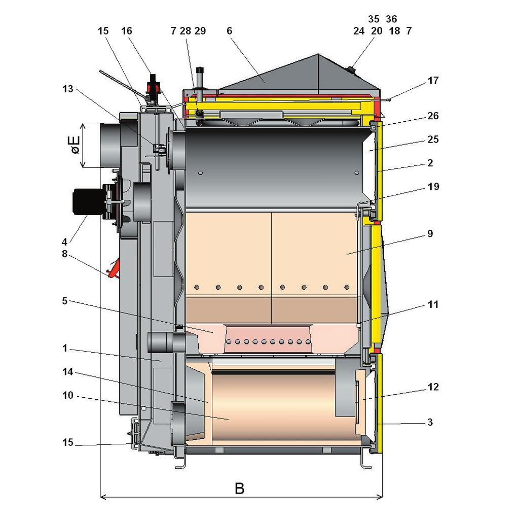
7 Instruction manual - Boiler drawings key 1. Boiler drum 2. Loading door 3. Ash-pan door 4. Ventilator - pressure - extraction 5. Heatproof shaped piece - nozzle 6. Control panel 7. Safety thermostat for pump - 95 C (only for DC75SE) 8. Control valve 9. Heat proof shaped piece for type GS - combustion area side 10. Heat proof shaped piece for type GS - spherical space 11. Sealing nozzle - 12x12 (14 x 14) 12. Heatproof shaped piece half moon 13. Ignition valve 14. Heat proof shaped piece for type GS - rear head of spherical space 15. Cleaning lid 16. Screen 17. Ignition valve pulling rod 18. Thermometer 19. Combustion area screen 20. Switch with an indicator light 22. Draught regulator - Honeywell FR Cooling loop protecting against overheating 24. Ventilator control thermostat (boiler) 25. Door filling - Sibral 26. Door sealing cord 18 x Ceramics - roof 28. Switching thermostat for pump - (only for DC75SE) 29. Ventilator condenser 31. Heatproof shaped piece half moon 32. Heatproof shaped piece combustion area plate Cleaning aperture (DC70S) 35. Waste gas thermostat 36. Safety thermostat Caution in overheat condition must be depressed) 37. Brake valve (only for DC40SE, DC50SE, DC75SE) 38. Spherical space D15 (P) for DC15E 39. Spherical space lining for DC15E 40. Pump thermostat for DC15E 41. Combustion area screen rear (model DCXX- SE) K flue gas duct neck L - water outlet from M - boiler water inlet to N - boiler filling valve P - pipe sleeve sleeve for cooling loop control valve sensor (TS 130, STS 20) Technical data Dimensions DC15E DC32S DC20GS DC22SX DC22S DC25S DC30SX DC18S DC30SE DC40SX DC25GS DC32GS DC40GS DC40SE DC50SE DC50S DC70S DC 80 DC75SE A B C D E F G H CH I J 6/4 6/4 6/4 6/4 6/4 6/4 6/4 6/4 6/4 6/
8 Instruction manual - Drawings of boilers 8-

9 Instruction manual - Cut away view - DC15E Cut away view DC70S Combustion chamber 3. Ash-pan door 5. Heatproof shaped piece - nozzle 31. Heatproof shaped piece half moon 32. Heatproof shaped piece combustion area plate. 34. Cleaning aperture -9
10 Instruction manual - Extraction ventilator schematics CAUTION The exhaust ventilator is provided disassembled. Assembler it on the smoke duct, fasten properly and test its slow operation 1 - Motor 2 - Plate 3 - Rotating wheel (stainless steel) 4 - Nut with left-handed thread and washer 5 - Wing nut 6 - Screw 7 - Large gasket (2 pcs) 8 - Small gasket 4. Type and seating of shaped pieces into combustion area 1. For type DC22S DC25S DC30SX DC32S DC50S DC40SE DC40SX DC50SE 27. Heatproof shaped piece roof is: - for boilers (DC22S, DC25S, DC30SX, DC32S, DC40SE, DC40SX) length 500 mm; - for boilers (DC50S, DC50SE) length 700 mm. Roof of the lower combustion area must always be fully pressed against the boiler rear wall. 10-
, 14.")
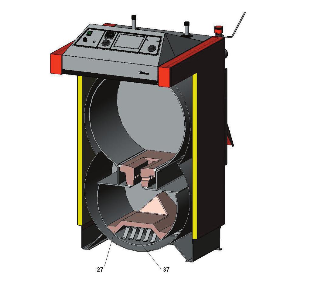
11 Instruction manual - 2. For type DC75SE Roof for this boiler type consist of two pieces see figure (DC75SE 2 x 500mm) 3. For type DC18S DC20GS DC22SX DC25GS DC32GS DC40GS DC30SE 10. Heatproof shaped piece - Spherical space (L+R side), 14. Heatproof shaped piece - rear face with a rearward recess The spherical space must be assembled in a way that ensures that the front section of the piece /10/ is 3 cm away from the front edge of the boiler frame. CAUTION do not turn the rear face when handling 4. For type 39. Combustion area lining (2 x 2 piece) 38. Spherical area DC15E Spherical area /14/ must be pushed to the rear of combustion area -11
12 Instruction manual - 5. For type 31. Heatproof shaped piece half moon. DC70S 32. Heatproof shaped piece combustion area plate (2 pieces) Front shaped piece is removed during boiler clean-up. It is positioned on the front side of the combustion chamber towards the door. 5. Boiler accessories Steel brush with accessories 1 pc Poker 1 pc Filling-in valve 1 pc Operating and maintenance instructions manual 1 pc Draught regulator - HONEYWELL FR 124 (DC50SE excluded) 1 pc Ashtray (only for DC XX GS, DC15E) 1 pc 6. Fuel Specified fuel is dry chopped log fire wood, Ø 8O 150mm, at least two years old, moisture 12% to 20%, caloric power MJ.kg ¹ and log length 330-1,000 mm as per boiler type. Fuel dimensions are stated in section 3 Technical Data. It is also possible to burn large pieces of wood waste in combination (max. 10%) with crude logs. Basic wood burning data You can ensure maximum output and a long service life if you burn wood which has been left for at least 2 years to dry. The following graph illustrates the relationship of moisture content to heating capacity of the fuel. The energy content declines dramatically with increased water contents. Example: Wood with 20% moisture contents has thermal power of 4 kwh /1 kg of wood Wood with 60% moisture contents has thermal power of 1.5 kwh /1 kg of wood Example spruce wood which has been stored for 1 year under shelter see graph 12-
13 Instruction manual - The boilers maximum output with wet fuel illustrated in the graph kw DC15 E - 8 DC 18 S - 13 DC 22 S - 14 DC 25 S - 19 DC 32 S - 24 DC 40 S(E) - 31 DC 50 S(E) - 39 DC 75 S(E) - 53 The information is relevant to other gasification boiler types. Boilers are not suitable for burning wood with moisture content lower than 12%. Fuel heating capacity Wood - type Heating capacity per 1 kg kcal kjoule kwh spruce ,5 pine ,4 birch ,3 oak ,2 beech ,0 Raw wood does not burn easily, produces a lot of smoke and substantially decreases the service life of your boiler and chimney. Boiler output drops as low as 50% and fuel consumption doubles. 7. Boiler bases Boiler type (mm) A B DC15E/DC18S/DC22SX DC20GS DC22S/DC25S/DC30SX DC30SE/DC32S/DC25GS/ DC32GS/DC40GS/DC40SX DC40SE DC50SE DC50S, DC70S DC75SE We recommend providing a concrete (metal) base under the boiler. -13
14 Instruction manual - 8. Environment type and boiler placement in a boiler room Boilers may be used in a basic environment - AA5/ AB5 as specified in Czech standard ČSN / Boilers must be placed in a boiler room with sufficient air access necessary for combustion. Placing boilers in living areas (including halls) is not permitted. The combustion air inlet aperture in the boiler room must be of minimum 250 cm2 for boilers of kw outputs Chimney - 2. Flue duct - 3. Boiler 9. Chimney Connecting the appliance to the chimney vent stack must always be carried out with the permission of the appropriate chimney authority. The vent stack must always be capable of providing sufficient draught and it must discharge the waste gas into the open atmosphere in a reliable manner for all possible operating conditions. The dimensions of the individual vent stack must be correct to ensure good functionality of the boiler; because the draught influences combustion, performance and the service life of the boiler. The chimney draught is directly dependent on its cross section, height and the inner wall ruggedness. It is not permitted to connect another appliance into a chimney into which a boiler is connected. The chimney diameter must not be smaller than the boiler outlet (min. 150 mm). The chimney draught must comply with the specified values (see technical data, page 6). The chimney must not be excessively high, otherwise the boiler effectiveness is decreased and the combustion is affected (the flame breaks ). In case of excessive draught, install a throttle valve in the flue gas duct between the boiler and the chimney. Indicative values of the chimney cross section dimensions: 20 x 20 cm height 7m Ø 20 cm height 8 m 15 x 15 cm height 11 m Ø 16 cm height 12 m Exact chimney dimensions are stipulated in Czech standard ČSN :2002. Specified chimney draught is stated in section 3 Technical Data. 10. Flue-gas duct The flue-gas duct must be connected into the chimney vent stack. If the boiler cannot be connected to the chimney directly, the appropriate flue-gas duct extension must be as short as possible in the given circumstances, but not longer than 1m, it must be without additional heating surface and must incline 14-
15 Instruction manual - upwards in the direction towards the chimney. Flue-gas ducts must be mechanically durable and sealed against combustion products and gas penetration, and it must be possible to clean them inside. The flue-gas ducts must not be lead through another person s apartment or property. The internal diameter of the flue-gas duct must not be larger than the internal diameter of the chimney intake and it must not decrease in width in the direction towards the chimney. Use of elbow-pipes is not suitable. Methods for providing flue-gas duct entries through flammable material structures are stipulated in appendices 2 and 3 of the Czech standard ČSN /97. These are appropriate for mobile installations, wooden cottages etc. 1 Waste gas thermometer 2 Cleaning aperture 3 Throttle valve (draught limiter) In case of excessive chimney draught, install a throttle valve (3) or draught limiter. 11. Fire prevention during installation and use of heating appliances Selected from ČSN /97 Fire safety of local appliances and heat sources. Safe distances When installing the appliance, keep a minimum safe distance of 200 mm from building materials. This distance is valid for boilers and flue-gas ducts positioned near flammable materials of the B, C1 and C2 flammability class materials (the flammability classes are listed in chart 1). It is necessary to double the 200 mm safe distance if the boilers and flue-gas ducts are placed near flammable materials of C3 class (see chart 1). It is also necessary to double the safe distance if the flammability class of the material in question cannot be determined. The safe distance can be decreased to one half (to 100 mm) if a heat insulating, non-combustible screen (asbestos board) of a 5 mm minimum thickness, is placed 25 mm from the protected combustible material (so called flammable insulation). The screening board or protection screen (on the protected object) must exceed the boiler outline including its flue-gas duct on each side by at least 150 mm and by at least 300 mm above its upper surface. The screening board or protection screen must be also used for all fixtures and fittings from combustible materials in cases where the safe distance cannot be maintained (such as in mobile structures or wooden cottages etc. - for more details see ČSN standard). The safe distance must be maintained even when placing fixtures and fittings near the boilers. If boilers are placed on floors from combustible materials, the floor must be fitted with a non-combustible, heat insulating pad exceeding the boiler s ground-outline on the side where the stoking and ash-pan apertures are, by at least 300 mm (in front of the aperture) and on all the other sides by at least 100 mm. The non-combustible, heat insulating pad can be made from any material of A flammability class. -15
 granite, sandstone, concrete, bricks, ceramic tiles,")
 Akumin, Izomin, Heraklit, Lignos, basalt felt boards, fibreglass boards, Novodur deciduous tree wood (oak, beech), Hobrex boards, plywood, Sirkolit, Werzalit, hardened paper (Formica), Ecrona)")


16 Instruction manual - Chart 1 Flammability classes of building materials and products A non-combustible B non-easily flammable C1 low degree of flammability C2 medium degree of flammability C3 high degree of flammability Building materials and products categorised by their flammability class (selected from Czech standard ČSN ) granite, sandstone, concrete, bricks, ceramic tiles, mortars, fireproofing plasters etc.) Akumin, Izomin, Heraklit, Lignos, basalt felt boards, fibreglass boards, Novodur deciduous tree wood (oak, beech), Hobrex boards, plywood, Sirkolit, Werzalit, hardened paper (Formica), Ecrona) coniferous tree wood (pine tree, larch, spruce), chipboards and cork boards, rubber flooring (Industrial, Super) fibreboards (Hobra, Sololak, Sololit), cellulose materials, polyurethane, polystyrene, polyethylene, foamed PVC In circumstances when there is a risk of temporary access of flammable gases or fumes, or during works when a temporary fire or explosion risk may possibly occur (such as gluing linoleum, PVC etc.) the boilers must be put out of operation long enough before the risk occurrence. No items from flammable materials may be placed on the boilers or near them for a distance lower than the specified safe distance. 12. Connecting boilers to the electric network Boilers are to be connected to a 230 V, 50 Hz electric network with electric cord with or without plug. The network connection is of the M type and when replacement is needed the service company must use the same type connection to replace it. Product must be placed in such way that the plug is accessible to operators (as per ČSN EN /1997). Connection may only be carried out by a person qualified in compliance with all valid regulations of the particular country. 13. Wiring diagram of electromechanical regulation with extraction ventilátor, type UCJ 4C52 (DC18S DC40SE) and with pressure ventilátor (DC80, DC7OS, DC22SX DC40SX) 16-


17 Instruction manual Wiring diagram of electromechanical regulation with an UCJ 4C52 ( DC5OSE) type extraction ventilator Possibility to connect the outlet to a pump with a 95 C safety thermostat 15. Wiring diagram of electromechanical regulation of the DC15E type boiler -17

18 Instruction manual Wiring diagram for DC75SE - electromechanical regulation with an UCJ 4C52 type extraction ventilator A and B connecters are used for feeding the heating system electronic regulation and this can be part of panels for some boiler types. 17. Obligatory ČSN EN standards dealing with boiler designing and boiler assembly ČSN EN ČSN /98 ČSN /96 ČSN EN /02 ČSN EN 1443/03 ČSN /97 ČSN /84 ČSN EN ČSN EN ČSN EN ČSN EN Solid fuel boilers for central heating - Central heating, designing and assembly - Safety devices for central heating and hot potable water heating - Designing chimneys and flue-gas ducting - Chimney structures general requirements - Fire safety of local appliances and heat sources - Construction materials flammability class - Floor heating Systems and components Definitions and symbols - Floor heating Systems and components Heat output calculation - Floor heating Systems and components Designing - Heaters Testing and test analysis CAUTION the boiler must be installed in compliance with a design prepared in advance. Installation may only be carried out by persons trained by the manufacturer. 18-
19 Instruction manual Choice and connection method of control and heating elements Boilers are provided to the user with the basic boiler performance control elements compliant with requirements for convenient heating and its safety. The regulation ensures that the required temperature of the water exiting the boiler (80-90 C) is adhered to. The control of mixing valves and pumps is not solved. With the exception of DC75SE, which is equipped with two thermostats 70 C (pump connection temperature during normal operation), 95 C (pump connection temperature during emergency state) for switching the pump in the boiler circle and with the exception of DC15E, which is equipped with thermostat place in the panel and an outlet for the pump in the boiler circle. Connection of these elements is illustrated in the wiring diagram. Each pump in the system must always be controlled by an individual thermostat to avoid a temperature drop of water returning to the boiler under 65 C. When connecting the boiler without an accumulation tank or equalizing tank, the pump placed in the heated building circuit must be switched on and off by an individual thermostat or electronic regulation so that it only operates when the pump in boiler circuit operates. If two thermostats are used each for switching one pump set the thermostat that switches the heated building circuit pump, to 80 C, and the thermostat that switches the boiler circuit pump, to 75 C. Both pumps may only be switched by one thermostat. We recommend to switch the pump in the boiler circle by the means of waste gas thermostat built in the boiler (during fire-up), if the boiler is connected with the accumulation tanks and Laddomat 21 and the if the gravity water circulation which prolongs the required temperature build up functions well in the boiler circle. When switching the pump in the boiler circle by using the waste gas thermostat built in the boiler panel, we recommend to install safety thermostat on the 95 C pump (see electric wiring diagrams). Thermostat in the boiler can be alternatively replaced with an attaching thermostat on the boiler outlet which connects the pump in the boiler circle when the temperature rises to 95 C (parallel connection with the waste gas thermostat). Setting the required water temperature for the building is always achieved by means of a three-way mixing valve. The mixing valve can be regulated manually or by electronic regulation, which contributes to a more convenient and economical operation of the heating system. The connection of all the elements is designed to suit specific conditions of the heating system. Electric installations related to the additional equipping the boilers with the above mentioned elements must be carried out by an expert in compliance with valid ČSN EN standards. When installing the boiler, we recommend using a closed expansion tank. However, an open tank may also be used if permitted in the standards of the specific country. The boiler must always be installed in a way which prevents overheating (and subsequent damage) even during a power cut. It is because the boiler has certain momentum. There are several ways of protecting the boiler from overheating. Connecting an overheat prevention cooling loop with a TS 130 3/4 A (95 C) or WATTS STS 20 (97 C) valve to the public water system. In cases of personal wells, the boiler can be additionally protected by using a back-up power supply (battery with an exchanger) for operation back up of at least one pump. Another option is connecting the boiler to an after-cooling tank and reversal zone valve. When installing the boiler, position the rear section 10 mm higher in order to facilitate circulating and air-bleeding. For the heating system regulation we recommend regulation elements provided by the following companies: a) KOMEXTHERM, Praha Telephone: b) KTR, Uherský Brod Telephone: c) Landis & Staefa Telephone:
20 Instruction manual Boiler corrosion protection The specified solution is connecting the boiler with Laddomat 21 or with a thermoregulatory valve, which can separate the boiler circuit from the heating circuit (primary and secondary circuits), and provide minimum of 65 C for water returning to boiler. The higher the temperature of water returning to the boiler, the fewer tars and acids condensing; which damage the boiler. Temperature of the outgoing water must permanently range between C. The combustion products (waste gas) temperature must not drop below 110 C during normal operation. Low waste gas temperature causes condensation of tars and acids even when the specified outgoing water temperature of (80-90 C) and returning water temperature of (65 C) are adhered to. These conditions may occur when using the boiler to heat hot potable water (HPW) in summer, or when heating only a section of the building. In this case we recommend connecting the boiler with accumulation tanks, or daily firing-up. For outputs of kw it is also possible to keep the minimum temperature of the returning water (65-75 C) by utilising a three-way mixing valve with an electric actuator and electronic regulation. 20. Specified boiler connection with Laddomat
21 Instruction manual Specified boiler connection with thermoregulation ATTENTION when connecting the cooling loop to prevent overheating, it is possible to omit the return valve on the thermo-valve and pump by pass. 22. Boiler connection with equilizing tank -21
22 Instruction manual Recommended wiring diagram with Laddomat 21 and accumulators Pipeline diameters if connected with accumulation tanks Boiler type and output section A section B in copper in steel in copper in steel D15E, DC18S, DC20GS 28x1 25 (1 ) 28x1 25 (1 ) DC22S, DC25S, DC25GS, DC22SX, DC30SX 28x1 25 (1 ) 28x1 25 (1 ) DC32S, DC32GS, DC30SE 35x1,5 32 (5/4 ) 28x1 25 (1 ) DC40GS, DC40SE, DC40SX 35x1,5 32 (5/4 ) 28x1 25 (1 ) DC50S, DC50SE 42x1,5 40 (6/4 ) 35x1,5 32 (5/4 ) DC70S, DC75SE 54x2 50 (2 ) 42x1,5 40 (6/4 ) 22-
23 Instruction manual Laddomat 21 With its construction, Laddomat 21 replaces the traditional connection composed of individual parts. It is composed of a cast-iron body, thermoregulatory valve, pump, non-return flap valve, ball valves and thermometers. When the water temperature reaches 78 C, the thermoregulatory valve opens the water supply from the storage tank. The connection with Laddomat 21 is considerably easier and therefore, we recommend it. A spare thermo-cartridge of 72 C is supplied with the Laddomat 21 device. It is used for boilers over 32 kw. OPERATION DATA Max. operating pressure 0,25 MPa Design pressure 0,25 MPa Test over pressure 0,33 MPa Hoghest operating temperature 100 C WARNING - Laddomat 21 is designed only for boilers with output up to 75 kw (inclusive). We recommend using it only with boilers with output up to 50 kw (inclusive). 25. Thermoregulatory valve ESBE Thermoregulatory valve type ESBE, TV 60 C is used with solid fuel boilers. When the boiler water temperature reaches + 60 C, the thermoregulatory valve opens and fluid from the building heating circuit (2) enters the boiler circuit ( 3 1). Inlets 1 and 3 always remain open. This ensures that the minimum temperature of the water returning to the boiler is maintained. If need be, a thermoregulatory valve set to a higher temperature (E.g. 72 C) may be used. Recommended sizes of the thermoregulatory valve TV 60 C. For boilers: D15E, DC18S, DC20GS, DC22S, DC22SX DC25S, DC25GS, DC30SX... DN 25 DC32S, DC32GS, DC40GS, DC40SE, DC40SX... DN 32 DC50S, DC50SE, DC70S, DC75SE... DN 40, DN 50-23
24 Instruction manual Operating a system with accumulation tanks Ignite the boiler and allow the accumulation tanks to charge to the required water temperature of C by the boiler s maximum output operation (2 to 4 loads). Then leave the boiler to stop burning. Then keep withdrawing heat from the storage utilising three-way valve for a period of time corresponding to the size of accumulation tanks and the external temperature. In the heating season (and if adhering to specified min. accumulation tanks volumes see chart) this could take 1 3 days. If the accumulation method cannot be used, then we recommend using at least one tank of l volume for equalising the boiler start-ups and run-outs. RECOMMENDED MINIMUM ACCUMULATION TANK VOLUMES Type DC15E DC18S DC20GS DC22S DC22SX DC25S DC25GS DC30SX DC32S DC32GS DC40GS DC40SE DC40SX DC50S DC50SE DC70S DC75SE DC100 Output Volume The standard ATMOS accumulation tanks provided TANK TYPE VOLUME ( l ) DIAMETER (mm) HEIGHT (mm) AN AN AN Tank insulation A suitable solution is joint mineral wool insulation of the particular number of tanks (of required volume) placed together into a plasterboard structure, or additional filling with granular insulation. When using the mineral wool, the specified minimum insulation thickness is 120 mm. Another option is purchasing tanks in a leather-cloth housing insulated by mineral wool (see the price list). Advantages The installation with accumulation tanks provides several advantages: - lower fuel consumption (by 20 30%), the boiler operates in full output and at an optimal effectiveness of % until the complete combustion of the fuel - prolonged boiler and chimney service life minimum formation of wood-tars and acids - possibility to combine it with other heating methods accumulated electric power, solar collectors - combination of wall radiators and floor heating - convenient heating and ideal fuel combustion - environmentally friendlier heating 24-
25 Instruction manual Connection of overheat protecting cooling loop with a safety valve Honeywell TS 130-3/4 A or WATTS STS20 (valve opening temperature C) safety valve 6 10 bar non-return flap valve expansion tank of min. 4 l volume non-return flap valve Attention cooling loop to prevent overheating must be used in compliance with EN ČSN only for overheating prevention (never for heating up warm service water). The TS 130-3/4 A or WATTS STS 20 valves, the sensor of which is placed in the rear of the boiler, prevent overheating in the following way: if the boiler water temperature rises above 95 C, the valve opens and allows water from public water supply system to enter the cooling loop. This water then absorbs the excessive energy and exits to the sewer. In case that a non-return flap valve has been installed to the cooling loop water inlet for the purpose of preventing reversed water flow (which might be caused by pressure drop in the public water supply system), the cooling loop must be fitted with a 6 10 bar safety valve or with an expansion vessel of minimum 4 l volume. The boiler must be protected against overheating at all times. If not, its damage or burst may occur. 28. Operating instructions Preparing boilers for operation Before putting boilers into operation, it is necessary to ensure that the system has been filled with water, and air-bled. Wood boilers must be operated in compliance with the instructions stipulated in this manual so that satisfactory and safe functioning is achieved. They can only be operated by adults. -25
26 Instruction manual - Ignition and operation Before fuel ignition, open the ignition valve /13/ by pulling the ignition valve pulling rod /17/ and reduce the waste gas thermostat (DC15E excluded) for the ignition (to minimum - 0 C). Through the top door /2/ insert dry wood kindling on the heatproof shaped piece /5/. Place the kindling perpendicularly to the channel recess in the shaped piece so that a 2 4 cm gap between the recess and fuel is created; which allows the waste gas passage. Place paper or wood wool on top of the kindling, then another layer of kindling and larger amount of dry wood. After ignition close the top door and open the lower door. For faster flaring up the extraction fan may be switched on (DC7OS, DC15E). When the fuel has caught sufficient fire, close the lower door, fill the storage tank completely with fuel and close the ignition valve with its pulling rod /17/. Set the waste gas thermostat into the operating position which it is necessary to determine for ideal operation. On the FR 124 draught (output) regulator /22/ set the required outgoing water temperature C (note DC50SE is not equipped with draught regulator FR 124). If the boiler should work as a gasification appliance, then a layer of glowing charcoal must be kept (known as reduction zone) above the gasifying nozzle. This can be achieved by burning dry firewood of suitable size. When burning moist wood, the burner does not operate as a gasification appliance, the fuel consumption increases dramatically, the boiler does not reach the required output and the service life of both - the boiler and the chimney - decreases. If the specified chimney draught is adhered to, the boiler operates up to 70% output without the ventilator. NOTE when burning wood for the first time, condensation occurs and condensed fluid leakage occurs this is not a defect. Condensation will disappear later. When burning small wood waste particles, it is necessary to monitor the waste gas temperature which must not exceed 320 C. Otherwise, the ventilator (S) may sustain damage. Wood-tar and condensate formation in the hopper is a side effect of wood gasification. NOTE during operation, all doors must be shut and the ignition valve pulling rod must be inserted, otherwise the ventilator (S) may sustain damage. Output regulation - electromechanical Output regulation is achieved by means of a control flap valve /8/ operated by the FR 124 draught regulator /22/ which automatically opens up or shuts down the valve /8/; depending on the pre-set outgoing water temperature (80-90 C) (DC50SE excluded). The output (draught) regulator adjustment should be done carefully because it not only regulates the output; but also protects the boiler against overheating. The setting should be in compliance with the enclosed Assembly and Setting Instructions for the HONEYWELL Braukmann FR 124 type regulator. The overheat protection function can be monitored by checking the regulator s functionality at temperature of 90 C. At this temperature, the control valve /8/ must be almost closed. It is necessary to seek and discover the best setting. You can visually inspect the control valve s /8/ position by looking from the rear side of the ventilator. The ventilator is controlled by a control thermostat situated on the boiler s panel. The regulation is based on the pre-set outgoing temperature value. The temperature set on the thermostat should be 5 C lower than the temperature set on the FR 124 draught regulator. (Indicated by dots on the thermostat scale). 26-
27 Instruction manual - The control panel also comprises of a waste gas thermostat which is used to switch the ventilator off when the fuel has been combusted. When igniting, position to the firing-up position (minimum value). When the fuel has sufficiently flared up, set it to the operating position in which the ventilator runs until the fuel has completely burnt out. It is necessary to seek and discover an optimal position of the thermostat; which depends on type of fuel, chimney draught and other conditions. The outgoing water temperature should be monitored on the thermometer /18/ situated on the control panel. There is also an irreversible safety thermostat on the panel. Wood supply gasification boiler DC50SE is not equipped with Honeywell draught regulator FR 124 and typical regulation valve (aperture for FR 124 on the water outlet from the boiler must be blinded). It is equipped with regulation valve with a servodrive and spring placed in the combustion air inlet. This valve is controlled with regulation and waste gas thermostat in accordance with outlet water temperature; like the draught ventilator. When the thermostat is switched off, it switches off automatically. Regulation valve is set by the manufacturer to a maximum opening of 30 mm. Maximum valve opening can be altered as necessary. This can change the boiler output and its combustion. Boiler DC15E is not equipped with a ventilator, regulation, waste gas and safety thermostat. Output regulation is carried out only with Honeywell FR 124 draught regulator, which controls the regulation air valve. Panel on DC15E type is equipped with a switch and thermostat for a pump. Draught regulator - HONEYWELL Braukmann FR 124 Assembly instructions Disassemble the lever /1/ and coupler /2/ and screw the regulator into the boiler. Setting Heat the boiler to approx. 80 C. Set the setting handle to the temperature read on the boiler thermometer. Tension the air flap valve chain in a way that provides the required boiler output; the gap at the air (control) flap valve may range between 3 50 mm. The valve minimum gap is set by a setscrew to 3 8 mm; boiler service-life prolonging feature, do not decrease. Otherwise, the boiler and ventilator may get covered in tar and their service life would be reduced. In cases where there are insufficient general draught conditions, slightly increase the permissible minimum gap. Draught regulator functional check Set the setting handle to the required temperature of water exiting the boiler (80-90 C). When the water temperature reaches its maximum of 95 C, the control flap valve must be fully closed (only providing the setscrew gap). It is always necessary to fine-tune the specified operating temperature (80-90 C) utilising the mixing valves behind the boiler either manually or by electronic regulation with electric actuator. -27
28 Instruction manual Boiler output and combustion setting For boilers with DC18S DC75SE draught ventilator Basic setting of primary-secondary air ratio (DC18S-DC50SE, DC20GS-DC40GS. DC22SX- DC40SX) Optimum setting: fully closed (5 mm) mm Maximum setting: fully closed (5 mm) mm Basic setting of primary-secondary air ratio for DC75SE boiler Optimum setting: fully closed (20 mm) mm Maximum setting: fully closed (20 mm) mm Without ventilator DC15E Optimum setting: fully closed (5 mm) mm Maximum setting: fully closed (5 mm) mm Boiler with compressive ventilator DC70S Basic setting of primary-secondary air ratio (70kW) Optimum setting: fully closed (5 mm) mm Maximum setting: fully closed (5 mm) mm 28-
. It is number no. 7 on the servo-drive scale. Maximum valve opening can be altered as necessary.")
29 Instruction manual - Setting the servo-drive controlled valve with in-built spring for boilers DC50SE Setting Optimal mm Minimum mm Maximum mm Regulation valve is set by the manufacturer to a maximum opening of 30 mm (see figure). It is number no. 7 on the servo-drive scale. Maximum valve opening can be altered as necessary. This can change the boiler output and its combustion. The valve is closed by the servo-drive (spring) when the ventilator is switched off. The valve closes during power failure. Minimum amount of air is attached to the valve s surface for the inhibition regime. Adjustments to settings should be done on the basis of the waste gas analyzer and maximum temperature; which must not exceed 320 C at the outlet to chimney, at stabilised nominal output /with closed ignition valve/. The boiler is set to optimal operating parameters by the manufacturer. Therefore, make adjustments to settings only in cases where the operation conditions are non-standard (for example - if insufficient chimney draught, pull the regulator pulling rod to its maximum). 30. Fuel refill Before fuelling, open the ignition valve /13/ with the pulling rod /17/. Do not switch the extraction ventilator off. Wait for approximately 10 seconds and slowly open the loading door /2/ so that any accumulated gases are first vented off into the flue-gas duct and not in the boiler room. Before opening the DC70 door, switch the pressure ventilator /4/ off using switch /20/. Cover the glowing charcoals with a wide log. Do not press the fuel on the gasifying nozzle, it can put the flame out. Always fill the hopper completely. In order to prevent excessive smoke formation, load new batch of fuel only after the previous fuel has combusted to at least one third of the loading volume. CAUTION during operation, the ignition valve pulling rod must be retracted, otherwise damage to the ventilator (S) will occur. Otherwise, the ventilator (S) will sustain damage. 31.Steady heat operation It is possible to use boilers for slow-burning operation, i.e. keeping the fire up overnight without the -29
30 Instruction manual - necessity to heat-up during the day. This is only permitted during wintertime. This operating method however decreases the boiler service life. Prepare the boiler for slow-burning operation in the following way: - place several (4 6) larger logs on a glowing layer of partially combusted fuel - turn the mixing valve down After the valve has been turned down, the boiler water temperature increases to C. - the control flap valve /8/ operated by the FR 124 Honeywell draught regulator automatically shuts down and the ventilator switches off (DC15E excluded) the boiler operates in maximum output mode In boilers prepared as previous, the fuel burns for 8 12 hours. The actual slow-burn combustion time depends on the amount of fuel placed in the boiler and on the actual quantity of consumed heat. Even if the boiler operates in the slow-burn mode, it has to keep the output water temperature ranging between C and returning water minimum temperature 65 C. 32. Boiler cleaning It is necessary to clean the boilers regularly and thoroughly every 3 to 5 days because the flue cinder accumulated in the fuel storage tank together with tars and acids dramatically decreases the boiler s service life and output and insulates the heat transfer surface. If excessive amount of cinder in the lower chamber is left to form, then the burn-off area is insufficient and damage to the ceramic nozzle handle or the boiler may occur. Carry out the cleaning procedure by first switching the extraction ventilator on (except for DC15EP), then open the loading door /2/ and sweep the cinder down through the slot into the lower chamber. Leave long pieces of wood which has not fully combusted (charcoals) in the hopper for the next time the boiler is used. Open the cleaning lid /15/ and clean the rear duct with a brush. If the brake valve is inserted in the duct (corrugated sheet), it must be removed before cleaning. Remove all the soot and cinder after opening the lower lid /15/. Open the lower door /3/ and clean the lower chamber from cinder and soot. Remove the layers of dust on the side walls of the lower combustion chamber with a poker or a brush. If there is a roof in the lower combustion area which contains a breaker (corrugated sheet DC40SE, DC50SE, DC75SE), it is necessary to remove the breaker when cleaning and removing the ash. The cleaning interval depends on the fuel quality (wood moisture content), heating intensity, chimney draught and other factors. We recommend cleaning the boilers once a week. Do not pull out the fireclay shaped piece /10/, /14/, /38/, /39/ when cleaning. At least once a year clean the extraction ventilator rotating wheel and via the cleaning hole, inspect the state of the primary to secondary air ratio regulation. For boilers DC50SE, special sheets are placed on the sides next to the gasification nozzles; the sheets improve the combustion quality. Area underneath these sheets must be cleaned regularly once per 7 to 14 days. Boilers DC70S must be checked at least 2x a year and the compressive ventilator and the air duct may need cleaning. If necessary, clean the area behind the heating area rear screen from tars and ash /41/, /19/. 30-

31 Instruction manual - Ceramic ash areas For type DC18S DC20GS DC22SX DC25GS DC32GS DC40GS DC30SE For type DC22S DC25S DC30SX DC32S DC50S DC40SE DC40SX DC50SE DC75SE Maximum ash quantity only up to the upper roof s edge level! For type DC15E Maximum ash quantity! NOTE regular and thorough cleaning is important for permanent stabilised output and a long service life of your boiler. If not cleaned properly, damage to the boiler may occur the manufacturer s guarantee is rendered invalid -31
Wood gasification process...3. Wood as a fuel...3. Boiler construction - its elements...4
 Wood gasification process... Wood as a fuel... Boiler construction - its elements...4 Boiler construction - materials...4 EKO advantages...4 Boiler construction - schematics... Boiler dimensions... Boiler
INSTALLATION AND OPERATING INSTRUCTIONS. Ariterm 60+
 INSTALLATION AND OPERATING INSTRUCTIONS Ariterm 60+ CONTENTS General.... 2 Installation.... 4-5 Installation of temperature limit valve... 6 Measurements and connections... 7 Technical specifications and
WOOD GASIFYING BOILER ATTACK DPX STANDARD / PROFI / LAMBDA INSTRUCTIONS FOR USE WWW. ATTACK.SK
 WOOD GASIFYING BOILER ATTACK DPX STANDARD / PROFI / LAMBDA INSTRUCTIONS FOR USE WWW. ATTACK.SK CONTENTS EN ATTACK DPX THE WOOD GASIFYING BOILER... 4 1 INTRODUCTION... 6 2 3 4 1.1 GENERAL DESCRIPTION...
INSTALLATION, OPERATION AND MAINTENANCE. Ariterm Vedo
 INSTALLATION, OPERATION AND MAINTENANCE Ariterm Vedo CONTENTS General...3 Installation...4-5 Laddomat 21 Connection diagram...6 Temperature control valve...7 About burning wood...8 Operation...9-11 Service
INSTALLATION, OPERATION AND MAINTENANCE. Ariterm Hybrid 20
 INSTALLATION, OPERATION AND MAINTENANCE Ariterm Hybrid 20 TABLE OF CONTENTS General...3 Installation... 4-5 Dimensions - with flue gas exhauster...6 Dimensions - without flue gas exhauster...7 Pipe installations...8
Gasification boiler PYROLYT INSTRUCTION MANUAL. ver. 1.1
 Gasification boiler PYROLYT INSTRUCTION MANUAL ver. 1.1 THERMOSTAHL would like to thank and congratulate you on your purchasing this boiler device and ensure that you have made a good choice. PYROLYT boiler
SOLID FUEL RANGE COOKERS TYPE 9105 TYPE 9107 OPERATION & MAINTENANCE MANUAL INSTALLATION MANUAL
 SOLID FUEL RANGE COOKERS TYPE 9105 TYPE 9107 OPERATION & MAINTENANCE MANUAL INSTALLATION MANUAL TYPE 9105, 9107 07/2014 TYPE 9105, 9107 07/2014 1 OPERATION & MAINTENANCE MANUAL Dear customer, Thank you
REV.01 /
 REV.01 / 2012 123794 CAUTION! Observe the safety instructions of this installation and maintenance manual before placing the boiler in operation. If an unqualified person carries out installation, adjustment,
Operation Manual - GB. Operation Manual.
 Operation Manual Contents 1. Application 5 2. Technical description 5 ayout of the instrument panel 6 3. Technical specifications 7 Captions for the diagrams of the boilers 8 Technical specifications
UNI. Cast-iron solid fuel boiler. Installation and operating instructions
 UNI Cast-iron solid fuel boiler Installation and operating instructions Rev. June 2010 Content: 1. Introduction 2. Characteristics of boilers 3. Technical parameters 4. Delivery and accessories 5. Location
Ladan. Wood gasification boiler. Instruction for use, installation and assembly of boiler.
 Ladan Wood gasification boiler Instruction for use, installation and assembly of boiler. Content Content...2 General description...3 Technical parameters...4 Protection against boiler overheating...5 Dimensional
Figure 1 Solid fuel cook-stove KMŠ 70 and KVŠ 90H
 Figure 1 Solid fuel cook-stove KMŠ 70 and KVŠ 90H 1. 2. 3. 4. 5. 6. 7. Fire box door Ash pan door Air inlet control Fuel drawer Side flue gas connector Oven door with double glass Protective cover for
INSTRUCTIONS MANUAL FOR USE AND MAINTENANCE
 INSTRUCTIONS MANUAL FOR USE AND MAINTENANCE Carbel models: C-60 Plus C-70 Plus C-80 Plus C-100 Plus C-70 Plus Double-sided C-80 Plus Double-sided C-100 Plus Double-sided CARBEL C/ Ciudad de Cartagena,
SOLID FUEL HEATING UNIT TYPES NPS 35 AND NPS 70 ORIGINAL INSTRUCTION MANUAL
 SOLID FUEL HEATING UNIT TYPES NPS 35 AND NPS 70 ORIGINAL INSTRUCTION MANUAL 1. General information The Original Instruction Manual constitutes an integral and material part of the product, and is to be
Index. Operating Instructions. Installation Instructions
 Index Information on the boiler plate Boiler dimensions, Boiler packaging dimensions Technical parameters Introduction Ensuring safety of equipment and people, Head loses 2 3 4 5 6 Operating Instructions
OPERATING INSTRUCTIONS with safety features
 Solid fuel boiler TKK3 with wood pellet burner TERMEC 70-90 KW OPERATING INSTRUCTIONS with safety features Prhova ka bb 22310 imanovci, Srbija Tel/Fax. +381 22 480404 +381 63 259422 oce@termomont.rs www.termomont.rs
BW Type Solid Fuel Boilers Installation and Maintenance Instructions
 BW Type Solid Fuel Boilers Installation and Maintenance Instructions This Installation and Maintenance Instructions contain important information for the safe and correct installation, start-up and trouble-free
Operating and installation instructions for Fire Lotus H586
 Operating and installation instructions for Fire Lotus H586 Version 1, 24 May 2016 Introduction Congratulations on your new Lotus Fire. We hope and believe that it will give you many hours of warmth.
Installation & Manual. Model T-25
 Installation & Manual TR Central Heating Stove With Solid Fuel Model T-25 Tested according to DIN EN 13240 For product efficiency and emission values, see the declaration of conformity! TABLE OF CONTENTS
PELLETS BURNER 15-60kW MOC
 PELLETS BURNER 15-60kW MOC. Please read those documentation before first start up the unit. Improper burner start may lead to its damage and may create a danger for end user! Table of Contents: 1. Admission
SOLID FUEL RANGE COOKER
 SOLID FUEL RANGE COOKER TYPE 9101 OPERATION & MAINTENANCE MANUAL INSTALLATION MANUAL TYPE 9101 07/2014 1 TYPE 9101 07/2014 2 OPERATION AND MAINTENACE MANUAL Dear customer, Thank you for purchasing of the
INSTRUCTION MANUAL & SERVICE MANUAL ORLAN 96 SUPER ORLAN 130 SUPER
 INSTRUCTION MANUAL & SERVICE MANUAL ORLAN 96 SUPER ORLAN 130 SUPER INSTRUCTION MANUAL Content 1. Boiler application...3 2. Principle of work...3 3. Description of the controller...4 3.1. Front panel of
Wood logs boiler with a gasication eect IGNIS KW. INSTRUCTIONS MANUAL for usage and maintenance
 Wood logs boiler with a gasication eect IGNIS 20-40 KW INSTRUCTIONS MANUAL for usage and maintenance Prhovacka bb 22310 Simanovci, Srbija Tel/Fax. +381 22 480404 +381 63 259422 oce@termomont.rs www.termomont.rs
Boiler Technical Specifications (2013)
") ACT Bioenergy Boiler Dimensions 0.5-0.85 Million Btu/h (150-250kW) Model CP500 CP600 CP750 CP850 Heat Output in MBtu/h (kw) 510 (150) 610 (180) 750 (220) 850 (250) Height ft (mm) 6 1 (1855) 6 1 (1855)
ACT Bioenergy Boiler Dimensions 0.5-0.85 Million Btu/h (150-250kW) Model CP500 CP600 CP750 CP850 Heat Output in MBtu/h (kw) 510 (150) 610 (180) 750 (220) 850 (250) Height ft (mm) 6 1 (1855) 6 1 (1855)
TECHNICAL PASSPORT INSTALLATION AND MAINTENANCE MANUAL
 Pellet boiler TECHNICAL PASSPORT INSTALLATION AND MAINTENANCE MANUAL SAFETY 1.1. Notes about this instruction This manual contains important information about proper installation, testing, use and maintenance
Heating, Air Conditioning, Ventilation. Отопление-Кондиционеры-Вентиляция. MTM 8-30 kw UNIVERSAL OIL HEATER OPERATING MANUAL
 Heating, Air Conditioning, Ventilation Отопление-Кондиционеры-Вентиляция MTM 8-30 kw UNIVERSAL OIL HEATER OPERATING MANUAL 1. Usage MTM 8-30 universal oil heater is designed for heating commercial rooms
WOOD GASIFYING BOILER ATTACK DPX STANDARD / PROFI / LAMBDA INSTRUCTIONS FOR USE
 WOOD GASIFYING BOILER ATTACK DPX STANDARD / PROFI / LAMBDA INSTRUCTIONS FOR USE W W W. A T T A C K. S K ATTACK DPX Wood gasifying boiler - Assembly, control heat up and attendance training is perfomed
ISO 9001 TUV CERT CE
 ISO 9001 TUV CERT CE INSTRUCTION MANUAL CONTENT 2 1. Boiler application 2. Principle of work 3. Description of the controller 3.1. Front panel of EKOSTER 2 3.2. Main functions of EKOSTER 2 4. Gasification
INSTALLATION AND SERVICE INSTRUCTIONS. The biggest Czech producer of fi replace inserts. Accurate and precise design of details
 The biggest Czech producer of fi replace inserts Accurate and precise design of details BeF Home, s. r. o. Kotvrdovice 277 679 07 Kotvrdovice Tel.: 516/428 240 Fax: 516/428 244 IČO: 255246 The best price
MANUAL FOR USE AND INSTALATION STOVE MODELS: D11-D17
 MANUAL FOR USE AND INSTALATION STOVE MODELS: D11-D17 CE Tested by the DIN EN 13240 15a B-VG Austria Type 1 Color Emajl d.o.o. Alaginci 87 a 34000 Požega Croatia www.color.hr team@color.hr 1 Attention!
SAUNA HEATER INSTALLATION AND OPERATING MANUAL
 SAUNA HEATER INSTALLATION AND OPERATING MANUAL Type Stoveman 13 Models 13R; 13R-M; 13; 13-M; 13R-LS; 13R-M-LS; 13-M-LS; 13-LS Heating output in the sauna room 15.4 kw Sauna room cubage 6-13 m³ Fuel Wood
KALVIS-2-20, 2-25, 2-30, 2-40
 - 2 - Attention! Get acquainted with this technical certificate before installing the boiler.it will allow you to install the boiler correctly and to run it as efficiently as possible. 1. Technical data.
Biomass. Biomass solid fuel boiler range
 Biomass Biomass solid fuel boiler range Biomass Fuelling positive change For more than150 years, Baxi has been at the forefront of heating technology Baxi leads the way with new and pioneering heating
VICTRIX 90 VICTRIX 115 Wall-hung condensing boilers for high power
 VICTRIX 90 VICTRIX 115 Wall-hung condensing boilers for high power VICTRIX 90 is the new wall-hung condensing boiler for room heating only, set-up for independent functioning and for that in cascade mode
Wood-burning boiler CBB. User Guide E
 EN Wood-burning boiler User Guide 300008541-001-E . Contents 1 Symbols used...........................................................................3 2 Important recommendations...............................................................3
USER MANUAL 9kW LILLY PELLET STOVE
 USER MANUAL 9kW LILLY PELLET STOVE Table of Contents.Overview of Stove Parts... 2.Technical Characteristics... 3 3.Important Information... 4 4.Pellet Specification...5 5.Technology... 6 6.Installation...
INSTRUCTIONS FOR INSTALLATION AND MANUAL Solid fuel stove for central heating THERMO IN
 INSTRUCTIONS FOR INSTALLATION AND MANUAL Solid fuel stove for central heating THERMO IN To respected customer, We are very pleased for your trust and your decision to buy our product. You made a good choice,
MANUAL. Page 1/44
 MANUAL FOR INSTALLATION AND OPERATION OF A HEATING SYSTEM, CONSISTING OF HOT WATER WOOD PELLET BOILER FROM SERIES PELLETHERM V4 AND AUTOMATED WOOD PELLET BURNER FROM SERIES GP IV http:// www.greenecotherm.eu
THE WOOD GASIFYING BOILER ATTACK SLX PROFI / LAMBDA TOUCH INSTRUCTIONS FOR USE
 THE WOOD GASIFYING BOILER ATTACK SLX PROFI / LAMBDA TOUCH INSTRUCTIONS FOR USE W W W. A T T A C K. S K CONTENT 1 INTRODUCTION... 5 2 3 4 5 6 1.1 GENERAL DESCRIPTION... 5 1.2 DESCRIPTION OF MARKINGS OF
Installation, operation and care Firewood boiler Vedolux 40 UB
 Installation, operation and care Firewood boiler Vedolux 40 UB 2008-09-23 Ver 2 Replaces: 05-11 VEDOLUX 40 UB Notes 0809 To be completed when the Vedolux 40 UB is installed Serial number:... Installation
VIADRUS HERCULES U 26 Manual for boiler operation and installation
 VIADRUS HERCULES U 26 Manual for boiler operation and installation GB_2016_48 2010 GB_ 2015_20_model 2010 Table of contents: page 1 Boiler use and advantages... 3 2 Boiler technical data... 3 3 Description...
HERCULES U 32 Manual for boiler operation and installation
 HERCULES U 32 Manual for boiler operation and installation GB_2017_20 GB_2015_46 Content p. 1 Boiler Use and Advantages... 3 2 Technical parameters of the boiler... 3 3 Description... 5 3.1 Boiler Construction...
PELLET BURNER PV 350
 PELLET BURNER PV 350 INSTRUCTION MANUAL v1.1 1 PRODUCT DESCRIPTION...3 2 SAFETY RULES...3 3 WARNINGS...4 4 INSTALLATION INSTRUCTIONS...5 4.1 BOILER REQUIREMENTS...5 4.2 PELLET CONTAINER...6 4.3 INSTALLATION
So old fashioned... As the combustion chamber is completely room sealed, it does not release any smells and does not dirty.
 ARREDO E BENESSERE So old fashioned... An intelligent choice When on a cold winters night the warm glowing flames of the KALDUS boiler are there to welcome you back home, you will be pleased that you decided
PANTHER P Automatic Boiler Operator's Manual
 KOVARSON s.r.o. Lhota u Vsetína 4 755 01, Vsetín tel. CZ: +420 571 420 926 tel. SK: +421 949 176 717 email: info@kovarson.cz PANTHER P Automatic Boiler Operator's Manual - 1 - Dear Customer, Thank you
SOLID FUEL RANGE COOKER TYPE 9114 TYPE /2016 0
 SOLID FUEL RANGE COOKER TYPE 9114 TYPE 9114 04/2016 0 OPERATION & MAINTENANCE MANUAL INSTALLATION MANUAL Declaration KVS EKODIVIZE, a. s. declares that the hygienic character of the baking accessories
INSTRUCTIONS FOR INSTALLATION, SETTING AND USE
 BUILT-IN FIREPLACE INSTRUCTIONS FOR INSTALLATION, SETTING AND USE 1. BUILT-IN FIREPLACE SPECIFICATION - WIDE 730 mm - DEPTH 426 mm - HEIGHT 543 mm - NOMINAL POWER 11 KW - CHIMNEY POT DIAMETER Ø 180 mm
PER-EKO type KSW & KSW PLUS Instruction Manual
 TABLE OF CONTENTS INTRODUCTION..... 3 1. GENERAL INFORMATION..... 3 1.1. Application.. 3 1.2. Fuel..... 3 1.3. Dimensions & technical parameters........ 4 2. BOILER TECHNICAL SPECIFICATION...... 4 2.1.
INSTALLATION AND OPERATING INSTRUCTIONS
 INSTALLATION AND OPERATING INSTRUCTIONS CONTENTS 2 6 7 8 9 10-12 16 17 18 18 19 2 GENERAL TRANSPORTATION, STORAGE AND OPENING THE PACKAGE Receiving the goods - Storage Opening the package 3 INSTALLATION
VIADRUS HERCULES U 24 Manual for boiler operation and installation
 VIADRUS HERCULES U 24 Manual for boiler operation and installation GB_2014_21 Table of contents page 1. Technical information... 3 1.1 Usage... 3 1.2 Boiler advantages... 3 1.3 Boiler technical data...
Remeha. Fuel oil/gas boilers P 520. Installation and Service Manual A
 Remeha Fuel oil/gas boilers EN Installation and Service Manual 300016859-001-A 63115 Declaration of conformity The appliance complies with the standard model described in declaration of compliance. It
INSTRUCTION MANUAL & SERVICE MANUAL ORLIGNO 200
 INSTRUCTION MANUAL & SERVICE MANUAL ORLIGNO 200 CE INSTRUCTION MANUAL Content 1. Boiler application...3 2. Principle of work...3 3. Description of the controller...4 3.1. Front panel of EKOSTER 2...4 3.2.
1. Contents Principle General information Parts list Assembly Technical drawing... 18
 1. Contents 1. Contents... 2. Principle... 2 3. General information... 3-7 4. Parts list... 8 5. Assembly... 9-17 6. Technical drawing... 18 2. Principle All instructions provided with products must be
Installation of a Brunner fireplace. General Indications
 Installation of a Brunner fireplace General Indications CONTENTS 1 Basic informations...3 2 Safety precautions...4 3 Combustion air...5 4 Requirements for location... 6 5 Overview of fire safety and heat
MANUAL INSTRUCTION Solid fuel cooker for central heating - SUPER-THERMO MAGNUM
 MANUAL INSTRUCTION Solid fuel cooker for central heating - SUPER-THERMO MAGNUM DEAR CUSTOMER, We appreciate your trust dedicated to us and your determination to buy our product. You made a good choice,
VIADRUS HERCULES Hercules U U26 AND INSTALLATION
 VIADRUS HERCULES Hercules U U26 MANUAL FOR BOILER Návod OPERATION k obsluze AND INSTALLATION Table of contents: page 1. Boiler use and advantages... 3 2. Boiler technical data... 3 3. Description... 8
OPERATION MANUAL RK-2006LPP AUGER FITTED SOLID FUEL BOILER TEMPERATURE CONTROLLER. Version DC19
 OPERATION MANUAL RK-2006LPP AUGER FITTED SOLID FUEL BOILER TEMPERATURE CONTROLLER Version DC19 1. Application. Controller RK-2006LPP is designed for temperature control of solid fuel fired water boilers
USER S MANUAL, MAINTENANCE MANUAL INSTALLATION INSTRUCTIONS
 D F:\Home\RD\ME\FUNNY\FUNNYGB.WP IN-FIRE Jubilee USER S MANUAL, MAINTENANCE MANUAL INSTALLATION INSTRUCTIONS 07DHIFFUA 03/99-1 - Dear Customer! Congratulations on the purchase of your new Bodart & Gonay
WHE 2.24 / WHE 2.24 FF
 EN Wall-hung gas boilers WHE 2.24 WHE 2.24 FF User Guide 300011777-001-C . Contents 1 Introduction.............................................................................3 1.1 Symbols used...........................................................................................3
PRODUCT INFORMATION SOLARBAYER-BOILER. Technical Hand Book. TÜV-tested according to DIN EN 303-5
 We design for your future PRODUCT INFORMATION SOLARBAYER-BOILER TÜV-tested according to DIN EN 303-5 Technical Hand Book Welcome among the log wood heaters Thank you for choosing a Solarbayer product.
Protection and Control of Solid Fuel Boilers
 Protection and Control of Solid Fuel Boilers thermal relief valves thermostatic valves and pump stations draft regulators www.regulus.eu BOILER PROTECTION AGAINST OVERHEATING Solid fuel boilers may get
Heating with log wood
 English Heating with log wood De Luxe 18-40 Lambda 18-40 1 Competence is our success... HERZ FACTS: 60 subsidiaries Group headquarter in Austria Research & development in Austria Austrian owner 2.600 employees
INSTRUCTIONS FOR INSTALLATION AND USE OF ZINO 700,900,1100
 INSTRUCTIONS FOR INSTALLATION AND USE OF ZINO 700,900,1100 English 09-2011 WARNING : THE SUPLIER TAKES NO RESPONSIBILITY FOR ANY POSSIBLE DAMAGE, POOR WORKING APPLIANCES AND ACCIDENT AS A RESULT OF INCORRECT
VIADRUS HERCULES U26 ECO Manual for boiler operation and installation
 VIADRUS HERCULES U26 ECO Manual for boiler operation and installation GB_2015_21 GB_2016_48 Table of contents: page 1 Boiler use and advantages... 3 2 Boiler technical data... 3 3 Description... 6 3.1
MG SERIES - ENERGY CLASS A. Meeting the. MG series 1 / 7
 Meeting the MG series 1 / 7 Dear clients, Thank you for placing your confidence in our company and congratulations for your choice! You have purchased one of the many products of Gekas Metal company, intended
Combined boiler. for solid fuel and pellets
 Combined boiler ATTACK WOOD&PELLET for solid fuel and pellets W W W. A T T A C K. S K MODEL STRUC TURE OF THE AT TACK BOILERS THE NEW LINE OF ATTACK BOILERS FOR WOOD AND PELLETS 3000 000 6000 4 ATTACK
Importance of a Draught Regulator
 Importance of a Draught Regulator The purpose of a chimney (stack) is to generate a draught (draft) that will transport smoke and fumes away from the point of combustion. The chimney design and arrangement
INSTRUCTIONS MANUAL FOR USE AND MAINTENANCE
 INSTRUCTIONS MANUAL FOR USE AND MAINTENANCE Carbel models: KRONOS 100 KRONOS 80 KRONOS 70 CARBEL C/ Ciudad de Cartagena, 22 46988 Polígono Industrial Fuente de Jarro (Paterna) Valencia Tel. 96 1340716
LOG BURNING BOILERS. Zeroridge Biomass Ed 17A
 A LOG BURNING BOILERS A3 ALOG BURNING BOILERS Overview HDG and SHT log boilers zeroridge Model information Heat output Fuel options and loading options Page HDG R Series Easy controller Fuelling chamber
INSTRUCTION MANUAL. for installation and operation of solid fuel cookers. Victoria and Victoria Lux
 INSTRUCTION MANUAL for installation and operation of solid fuel cookers Victoria and Victoria Lux VICTORIA-05 Ltd. CONTENTS 1. Introduction... 3 2. Technical specifications and description... 3 3. Cooker
1 VICTRIX ZEUS Superior kw I features
 Wall-hung condensing VICTRIX ZEUS Superior kw I is the new range of wall-hung condensing boilers with 54 litre stainless steel storage tank available in two versions with nominal heat output of 26 kw and
Fireplace inserts. Model SK1000, SK2000. Installation instructions Care and firing instructions
 Fireplace inserts Model SK1000, SK2000 Installation instructions Care and firing instructions CONTENTS CONTENTS...2 GENERAL INFORMATION...3 IMPORTANT POINTS...3 PRECONDITIONS...4 Building notice Flue Combustion
SERVICE AND INSTALLATION MANUAL FOR CENTRAL HEATING BOILER BENEKOV R100
 SERVICE AND INSTALLATION MANUAL FOR CENTRAL HEATING BOILER BENEKOV R100 1 Dear customer, thank you for purchasing the automatic boiler BENEKOV R100 and the confidence in the products manufactured by BENEKOVterm
Installation and Operating Instructions
 Installation and Operating Instructions Klapi heater 12/2017 Contents 2 1 General safety instructions 3 2 Klapi heater 4 Heater components 4 3 Technical specifications 5 Rated power, efficiency, emissions,
Installation, operation and care. Pellmax UB. Burner not included Replaces:
 Installation, operation and care Burner not included 2011-11-11 ver: Replaces: Contents 11.11 otes...3 General...4 Function...4 Technical data...5 System principle Pellmax with radiator and tank-in-tank
FIREWOOD HOT WATER CENTRAL HEATING BOILERS MODEL: STADLER TR
 FIREWOOD HOT WATER CENTRAL HEATING BOILERS MODEL: STADLER TR STADLER TR firewood hot water central heating boilers provide comfortable and energy saving heating. Such heating is enabled with integration
LISEO Insert. European Standard Certification UNE EN inserts. LISEO s.r.o. Folknářská 1246/21 Děčín 2 Nové Město
 LISEO Insert European Standard Certification UNE EN-13229 inserts LISEO s.r.o. Folknářská 1246/21 Děčín 2 Nové Město 405 02 INTRODUCTION.4 1. GUARANTEE CONDITIONS.4 1.1. SAFETY WARNINGS....4 1.2. GUARANTEE
EWI-THERM Hot-Air Heating Systems Types Prestige-SE, Optimal-E and H-F-L
 EWI-THERM Hot-Air Heating Systems Types Prestige-SE, Optimal-E and H-F-L Chopped wood Chips/sawdust Wooden pieces Chip briquettes.. the useful and economic alternative to oil, gas and electricity Your
Malm Fireplaces, Inc. 368 Yolanda Avenue, Santa Rosa, CA (707) Fax: (707)
 Fax: (707)") Malm Fireplaces, Inc. 368 Yolanda Avenue, Santa Rosa, CA 95404 (707) 523-7747 - Fax: (707) 571-8036 info@malmfireplaces.com Fire Drum 2 Tested to U/L Standards 1482 and 737 Assembly And Installation Instructions
Malm Fireplaces, Inc. 368 Yolanda Avenue, Santa Rosa, CA 95404 (707) 523-7747 - Fax: (707) 571-8036 info@malmfireplaces.com Fire Drum 2 Tested to U/L Standards 1482 and 737 Assembly And Installation Instructions
DH-Direct Fired Poultry Farm Diesel Heater
 DH-Direct Fired Poultry Farm Diesel Heater Comparison of Diesel Heater to Gas Heater Diesel LPG Gas LPG Gas KW 43 70 120 Fuel consumption/hr 3 5.1 8.8 Heat output 37000 60000 100000 Cost of fuel/lit or
BIOMASS BOILER ATTACK PELLET 30 AUTOMATIC PLUS
 BIOMASS BOILER ATTACK PELLET 30 AUTOMATIC PLUS W W W. A T T A C K. S K MODEL STRUC TURE OF THE AT TACK BOILERS THE NEW LINE OF ATTACK BOILERS FOR WOOD AND PELLETS 3000 000 6000 4 ATTACK FD PELLET yattack
Solid fuel hot water boiler TKH KW INSTRUCTIONS MANUAL for usage and maintenance
 Solid fuel hot water boiler TKH 250-400 KW INSTRUCTIONS MANUAL for usage and maintenance Prhovacka bb 22310 Simanovci, Srbija Tel/Fax. +381 22 480404 +381 63 259422 oce@termomont.rs www.termomont.rs April
1. GENERAL SAFETY RULES
 ID180 & ID290 Indirect-Fired Diesel/Oil Construction Heaters Sure Flame Products Lethbridge, Alberta, Canada Telephone: (403)328-5353 Fax: (403)328-9956 www.sureflame.ca July 12, 2006 Service and Maintenance
Rocket heater GAMERA
 Rocket heater GAMERA High efficiency heater on hard fuel Manufacturer: AGNON Ltd., Bulgaria Hissarya, 4 Han Kubrat STR. +359 885 525 464 WWW.GAMERA.EU ROCKETGAMERA@GMAIL.COM ATTENTION! Read the following
HEATING BOILERS Astra G-18 E Astra G-25 E Astra G-32 E Astra G-40 E
 ASTRA MACHINERY PLANT AB ANNO 1929 HEATING BOILERS Astra G-18 E Astra G-25 E Astra G-32 E Astra G-40 E INSTALLATION AND OPERATION MANUAL CONTACT INFORMATION OF THE FACTORY: MACHINERY PLANT ASTRA AB ULONŲ
TermEfekt USER S MANUAL AIR HEATER. Model PGA 14
 Przedsiębiorstwo Produkcyjno-Wdrożeniowe ARAJ sp. z o.o. 55-080 Kąty Wrocławskie, ul. Mireckiego 30 POLAND USER S MANUAL AIR HEATER TermEfekt Model PGA 14 Kąty Wrocławskie, 2004 Product identification
Operation and installation manual
 1 Operation and installation manual. 2015.12.07 ORIGINAL MANUAL part 1/2 Dear User, To fully understand the principles of proper and economical operation of the boiler and to make it comfortable and safe,
- 12, , TECHNICAL INSTRUCTIONS
 HEATING TECHNIQUE Centrometal d.o.o. - Glavna, Macinec, Croatia, tel: +8 7, fax: +8 7 TECHNICAL INSTRUCTIONS for installation, use and maintenance of hot water boiler and installation of additional equipment
LISEO STOVES. European Standard Certification UNE EN stoves. LISEO s.r.o. Folknářská 1246/21 Děčín 2 Nové Město
 LISEO STOVES European Standard Certification UNE EN-13240 stoves LISEO s.r.o. Folknářská 1246/21 Děčín 2 Nové Město 405 02 INTRODUCTION.3 2 1. GUARANTEE CONDITIONS.3 1.1. SAFETY WARNINGS..3 1.2. GUARANTEE
Specifications 3. Bladder 5. Chimney 12. Air Supply 12. Anti-Rollout Device and Ash Auger Tube 14. Timer 15
 TABLE OF CONTENTS Page No. Specifications 3 Bladder 5 Fire Door 7 Chimney 12 Air Supply 12 Anti-Rollout Device and Ash Auger Tube 14 Timer 15 Supply Line and Return Line Threaded Connectors 15 Low Water
HEATING BOILERS Astra H-25 E Astra H-32 E Astra H-45 E
 ASTRA MACHINERY PLANT AB ANNO 1929 HEATING BOILERS Astra H-25 E Astra H-32 E Astra H-45 E CONTACT INFORMATION OF THE FACTORY: MACHINERY PLANT ASTRA AB ULONŲ G. 33, LT-62161 ALYTUS, LITHUANIA TEL.: +370
INSTRUCTION. for installation and operation of solid fuel fireplace
 INSTRUCTION for installation and operation of solid fuel fireplace SKLADOVA TEHNIKA Division Bitova tehnika 2 Ivan Momchilov St. 5100 Gorna Oryahovitsa CONTENTS 1.Introduction...3 2.Assembling of the fireplace...3
AIREX 2S WOOD PYROLYSIS SUCKING FAN
 AIREX S WOOD PYROLYSIS SUCKING FAN To optimize green energy AIREX S constitutes the evolution of the firewood boilers range: total gasification inverted flame with sucking fan especially suitable to the
TERMOCAST MAXI. Cast iron boiler for solid fuel firing. Installation and User Manual
 TERMOCAST MAXI Cast iron boiler for solid fuel firing Installation and User Manual 2195 Thank you for purchasing Maxi boiler. Please read this manual carefully before installation and operation of your
Aquaflam Wood boiler stoves and fireplace inserts
 www.hsflamingo.com Aquaflam Wood boiler stoves and fireplace inserts AQUAFLAM wood boiler stoves and fireplace inserts from the HS Flamingo workshop have many above-standard features. These innovative
Operating manual. Wood gasification boiler at kw. Orlan STANDARD, SUPER IRL
 Operating manual Wood gasification boiler at 18-80 kw Orlan STANDARD, SUPER IRL ISO 14001 ISO 9001 Contents 1. Boiler s use...3 2. Procedure rule...4 3. Installation...4 3.1. Diagram of chimney choice
W W W. A T T A C K. S K
 Combined boiler ATTACK WOOD&PELLET for WoOd and pellets INSTRUCTIONS FOR USE W W W. A T T A C K. S K CONTENTS CONTENTS... 2 1. GENERAL INFORMATION... 4 1.1 INTRODUCTION... 4 1.2. SAFETY... 4 1.3 BOILER
JÄSPI Solid Fuel Boiler
 JÄSPI Solid Fuel Boiler JÄSPI Solid Fuel Boilers Firewood used in solid fuel heating is a cost-efficient, renewable, and environmentally friendly energy source. The length of firewood can vary from 0.3
INSTALLATION AND OPERATION MANUAL FOR HUUM DROP ELECTRIC SAUNA HEATER
 INSTALLATION AND OPERATION MANUAL FOR HUUM DROP ELECTRIC SAUNA HEATER 2 Table of Contents 1. THINGS TO CHECK BEFORE INSTALLATION... 2 2. INSTALLATION... 2 3. CONTROLLING THE HEATER... 5 4. GUARD RAILS...
INSTALLATION, OPERATION AND MAINTENANCE. ARITERM SWEDEN AB Installation, Operation & Maintenance /28
 INSTALLATION, OPERATION AND MAINTENANCE ARITERM SWEDEN AB Installation, Operation & Maintenance - 2009.02.18-1/28 CONTENTS IMPORTANT INFORMATION 4 4 5 Notification to building authority Inspection Sweeping