Heat pump... Instructions for installation and use. Ed. 09/2009 Réf. :
|
|
|
- Marjory Thornton
- 5 years ago
- Views:
Transcription


1 F GB Heat pump... Instructions for installation and use P I Ed. 09/2009 Réf. :
2 IMPORTANT These installation instructions are an integral part of the product and must be given to the installer and kept by the user. The warnings and indications contained in the present handbook must be carefully read and understood as they provide important information relative to handling and operating safety. This handbook must therefore always be kept available for later consultation. Installation must be carried out in compliance with valid regulations and the manufacturer s instructions by a qualified professional. The term «qualified professional» refers to a person possessing the technical knowledge associated with Z.P.C.E. components and heating installations. An installation error could result in physical injury to persons or animals as well as mechanical damage for which the manufacturer may under no circumstances be held responsible. After having unpacked the heat pump, the content should be checked for possible damage. Before connecting the heat pump, ensure that the data provided by Z.P.C.E. is compatible with the true installation conditions and does not exceed the maximum authorised limits for the product in question. Before beginning any installation, handling or repair work on the heat pump, always isolate the electrical power supply to the unit. In the case of a fault and/or operating error on the heat pump, the electrical power supply must be isolated and no attempt should be made to repair the fault. Repair work may only be carried out by an authorised technical assistance service using original spare parts only. Non-respect of the aforementioned clauses may have a negative influence on the operating safety of the heat pump. To guarantee the efficiency and correct operation of the heat pump, it is important to ensure it is regularly maintained in compliance with the instructions provided by Z.P.C.E. In the case where a heat pump is sold or transferred to another user, always ensure that all technical documentation is sent with the equipment to be used by the new user or installer. This heat pump may only be used for the purpose for which it was designed: to heat a swimming pool; all other uses must be considered inappropriate, incorrect or even dangerous. All contractual or extra-contractual responsibilities of Z.P.C.E. will be considered nil and void for any damage caused by installation or operating errors, or due to non-respect of the instructions provided by Z.P.C.E. or valid installation standards for the equipment object of the present document.
3 CONTENTS 1 General General terms of delivery Voltage Water treatment Description Presentation Edenpac 1, 2, 3, 4 and Edenpac Edenpac 7 and Dimensional characteristics Edenpac 1, 2, 3, 4 and Edenpac 6, 7 and 8 3 Installation Connections Access to the electrical card Edenpac with single fan Edenpac with double fan 4.2 Hydraulic connections Electric connections Regulator operation Presentation Setting the target temperature Starting up Check Start up the heat pump Checking Troubleshooting Winter storage Maintenance instructions Recycling the product Electrical diagrams Electrical diagram EdenPAC single-phase Electrical diagrams EdenPAC three-phase


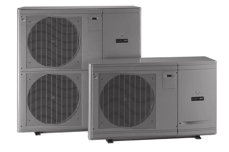
4 1. GENERAL 1.1 General terms of delivery Any equipment, even CARRIAGE and PACKING FREE, travel at the consignee s risk. The consignee shall make reserves in writing on the CARRIER S delivery bill if he notes damage caused during transport (confirmation to be sent to the CARRIER within 48 hours by registered mail with acknowledgement of receipt). Reminder: The unit must be shipped and stored in the upright position on a pallet and in the original packaging. In the contrary case, place the unit in the vertical position on the pallet and check its global state (in case of doubt regarding the unit s good state of operation establish reserves in writing with the carrier). Under no circumstances may the heat pump be operated immediately if it was placed horizontally. Wait at least 12 hours before operating the pump 1.2 Voltage Prior to any operation, check that the voltage on the name plate of the appliance corresponds to the mains voltage provided on site. 1.3 Water treatment In order to use our appliances under the best conditions, the following parameters must be respected: free chlorine: max. 2.5 mg/l, total bromine: max. 5.5 mg/l, ph between 6.9 and 8.0. If chemical or electrophysical disinfection systems are used, the installer and user must contact the supplier to ensure they are compatible with our materials. These systems must be installed after the heating system. 2. DESCRIPTION 2.1 Presentation Contents after unpacking: The unit with its instructions, warranty card + + Note: inside the appliance you will find a sachet of accessories. To extract it, see paragraph 4.1 of these instructions. Content of sachet: two sealing rings + two half-union connectors Ø50 with strap - four silent blocks a plastic cap - a grooved elbow union - four anchor bolts and dowels (only supplied with double fan unit). Must be installed with a double fan machine 2
 12 Pool inlet water connection (40/49")
5 2.1.1 Edenpac 1, 2, 3, 4 and Front panel with polypropylene grid 2 Motor fan unit 3 Access door to digital display (EVK) 4 Electric board 5 Flow switch 6 TITANIUM condenser 7 Control sensor 8 Cased SCROLL compressor 9 Arched plate fin evaporator Anti-frost sensor 11 Fastening plates (with silent blocks) 12 Pool inlet water connection (40/49 male screw fastening) 13 Packing gland (and/or cable inlet) 14 Pool outlet water connection (40/49 male screw fastening) 2 15 Removable polypropylene panel to access the technical compartment 16 Closing snap clips 17 Phase order relay on three-phase PAC Dehydrator Grooved elbow Plastic plug EVK digital display front panel EVK control plate Connecting cable between the plate and the EVK digital display 4/20 ma pressure sensor Progressive starter on single-phase PAC 16 Attention! Never use the panel reinforcement as a load-bearing support. 15 3

 4 Electric board 5 Flow switch 6 TITANIUM condenser 7")
 12 Pool inlet water connection (40/49 male")
 15 Removable polypropylene panel to access the technical")

6 2.1.2 Edenpac Attention! Never use the panel reinforcement as a load-bearing support Front panel with polypropylene grid 2 Motor fan unit 3 Access door to digital display (EVK) 4 Electric board 5 Flow switch 6 TITANIUM condenser 7 Control sensor 8 Cased SCROLL compressor 9 Arched plate fin evaporator Anti-frost sensor 11 Fastening plates (with silent blocks) 12 Pool inlet water connection (40/49 male screw fastening) 13 Packing gland (and/or cable inlet) 14 Pool outlet water connection (40/49 male screw fastening) 15 Removable polypropylene panel to access the technical compartment 16 Closing snap clips 17 Phase order relay on three-phase PAC Dehydrator Grooved elbow Plastic plug EVK digital display front panel EVK control plate Connecting cable between the plate and the EVK digital display 4/20 ma pressure sensor 4
 9 Arched plate fin evaporator Anti-frost sensor 11 Fastening plates 12 Pool")
 15 Removable polypropylene panel to access the technical compartment 16 Closing snap clips 1 EVK")
7 2.1.3 Edenpac 7 and Attention! Never use the panel reinforcement as a load-bearing support Access door to digital display (EVK) 9 Arched plate fin evaporator Anti-frost sensor 11 Fastening plates 12 Pool inlet water connection (40/49 male screw fastening) 13 Packing gland (and/or cable inlet) 14 Pool outlet water connection (40/49 male screw fastening) 15 Removable polypropylene panel to access the technical compartment 16 Closing snap clips 1 EVK digital display front panel 5
8 2.2 Dimensional characteristics Edenpac 1, 2, 3, 4 and 5 Dimensions of the appliance with packaging (in mm): To be transported upright in its original packaging close to the installation site. 870 Weight of Edenpac 1 with packaging: 96 kg Weight of Edenpac 2 with packaging: 98 kg Weight of Edenpac 3 with packaging: 101 kg Weight of Edenpac 4-5 with packaging: 110 kg 6
9 2.2.2 Edenpac 6, 7 and 8 Side view EdenPAC 6 Side view EdenPAC 7 and 8 Rear view EdenPAC 6 Rear view EdenPAC 7 and 8 Dimensions of the appliance with packaging (in mm) : To be transported upright in its original packaging close to the installation site Weight of Edenpac 6 with packaging: 145 kg Weight of Edenpac 7 with packaging: 175 kg Weight of Edenpac 8 with packaging: 170 kg 7
10 3. INSTALLATION Tools required for installation: - 1 set of flat head screwdrivers - 1 set of crosshead screwdrivers - 1 cutter - 1 wire stripper - 1 pipe or round head spanner 13-1 ratchet spanner - 1 pliers - 2 straps (for handling) Choose the appliance installation site according to the following criteria: the appliance must be installed outdoors the clearance around the appliance must be respected (see minimum dimensions on the drawings below) to avoid recycling of cold air produced. vers égout 4 m Dense obstacle (hedge, wall, fencing). the installation must be simple and allow for easy maintenance interventions. the appliance must be installed on a solid base (fastening centre distance 810 x 370) and protected against flooding (using a «concrete» base with drain facility for condensation or installation of an additional condensation evacuation kit placed at your disposal in the accessories sachet). The silent blocks supplied must be used, paying attention not to compress them too much when tightening the fastening screws. To use the additional condensation evacuation kit: - Use the grooved elbow union and cap. - The tank is equipped with two evacuation holes, one for the cap and the other for the grooved elbow union (their position is interchangeable). Note: To facilitate installation raise the unit 100 mm above the ground with the additional blocks made of a hard, water-resistant material (not supplied). the appliance must be level to allow for the gravitational evacuation of possible condensation produced during operation. 8

11 the blower must not be directed towards surrounding windows. vibrations and noise must not be transmitted to a building close by. the heat pump must be installed at a minimum distance from the end of the pool, as defined by the applicable national electrical standards. In France, the NF C standard (section 702) specifies that this device must be installed more than 2 meters from any basin or water reserve. In case it may be subjected to water jets, provide for a minimum distance of 3.5 meters. Attention! Do not lift the appliance by picking it up at the front and/or the water inlet/outlet points. Use 2 lifting slings (not supplied) placed on either side of the appliance (see drawing below). The handle on the right side may be used only to help with the final positioning of the appliance. Slings Do not install the heat pump close to an inflammable gas source. Do not install the heat pump close to a road or path to protect the appliance against mud splashing. Avoid places that are subject to strong winds, in particular if the wind blows against the appliance s air outlet. The installation as well as electric and hydraulic connections must be carried out in compliance with applicable standards, in particular standard NF C for France (equivalent to CE I 364). Keep the appliance out of reach of children. 4. CONNECTIONS 4.1 Access to the electric card Edenpac with single fan Turn the clips ¼ turn clockwise on the front panel 1 using a flat head screwdriver. Unscrew the 2 screws 2 and 3 on the right side using a cross head screwdriver. Slide the entire front panel forward and then down

12 4.1.2 Edenpac with double fan Turn the 2 clips 1a and 1b in the front ¼ turn clockwise using a flat head screwdriver. Unscrew the 2 screws 2 and 3 on the right side using a cross head screwdriver. Slide the entire front panel forward and then down a 1b 4.2 Hydraulic connections Connect the appliance s PVC Ø 50 hose water inlet and outlet (according to symbols) to the removable fittings provided with the heat pump. See symbols : for inlet and for outlet. Connection is established with a by-pass on the pool filtration circuit after the filter and before the water treatment device (see diagrams below). - Hydraulic circuit test pressure: 3 bars - Hydraulic circuit operating pressure: 1.5 bar Edenpac 1,2,3,4 and 5: average water flow 3.8 to 6.5 m³/h- pressure drop 1.3 to 1.7 mce (0.13 to 0.17 bar) V1 V2 V3 V5 V4 V1-V2-V3: By-pass valve V5-V4: Regulator valve* * Recommended to facilitate adjustment close to the machine. 10
13 Edenpac 6, 7 and 8: average water flow 7.5 to 10 m³/h- pressure drop 1.1 to 1.3 mce (0.11 to 0.13 bar) With EdenPAC 7 and 8 V5 V1 V4 V2 V3 V5 V4 V1-V2-V3: By-pass valve V5-V4: Regulator valve* * Recommended to facilitate adjustment close to the unit. 4.3 Electric connections The power supply of the heat pump must pass via a protection facility and circuit-breaker (not supplied) in compliance with applicable standards and regulations. The appliance is foreseen for connection to the mains circuit with TT and TN.S neutral connection (according to NF C or national standards in force). Supply cable section: protection: - Edenpac 1: 3 x 2.5 mm²* (single-phase 230V/1/50Hz) 16 A - Edenpac 2: 3 x 2.5 mm²* (single-phase 230V/1/50Hz) 16 A - Edenpac 3: 3 x 4 mm²* (single-phase 230V/1/50Hz) 20 A - Edenpac 3: 5 x 2.5 mm²* (three-phase 400V/3N/50Hz) 10 A - Edenpac 4: 3 x 6 mm²* (single-phase 230V/1/50Hz) 25 A - Edenpac 5: 5 x 2.5 mm²* (three-phase 400V/3N/50Hz) 12 A - Edenpac 6: 5 x 2.5 mm²* (three-phase 400V/3N/50Hz) 16 A - Edenpac 7: 3 x 10 mm²* (single-phase 230V/1/50Hz) 50 A - Edenpac 8: 5 x 4 mm²* (three-phase 400V/3N/50Hz) 25 A * This section is indicative and must be checked and adapted, if necessary, according to installation conditions. Electrical protection: circuit breaker (curve D) or fuse (Am) delayed designed for motors adapted to the type of unit (refer to the protection values above) with a protection system by 30 ma differential on the incoming supply side (circuit breaker or switch). Configuration of supply terminal In single phase 230V 50Hz with neutral + phase + earth Configuration of supply terminal In three-phase 400V 50Hz with neutral + phase + earth Note: The acceptable voltage variation during operation is ± 10% The cable ways and ducts must be fastened. Only use cable suitable for outdoor use. Use the packing glands and cable inlets to feed the cables into the unit. 11
14 Optional remote control functions: Remote On/Off start up: The terminals 26 and 27 of the Edenpac heat pump enable a remote start up by means of a switch or any other device. The heat pump is supplied with a jumper between these terminals. If this function is used, the jumper shall be removed. Otherwise it shall be kept. Priority to heating: A heating device, whatever it is, is designed to heat the water of the pool only when the water circulates. Most of the time, a pool is filtered between 6 and 8 hours a day. But such a time can t be sufficient sometimes to maintain the water at the desired temperature, depending on the seasons. This is the reason why the Edenpac, like all models of ZPCE s range, is equipped with the priority to heating function that will manage the temperature of the pool, taking itself the time to do it without caring of the scheduled time of operation of the filtration. Terminals 4 and 5 shall be connected to the terminals of the filtration timer (see attached diagram). Every hour, the contact between 4 and 5 is going to be closed, starting up the filtration for 5 minutes. If after 5 minutes, the temperature of the water is over the required temperature, the filtration shuts off for one more hour. Otherwise, the filtration and the heat pump are going to keep on operating until the desired temperature is reached. By this mean, the user is sure the water is always ready for bath, at day or at night. If this option is not used, the heat pump will operate only while the filtration runs. Terminal rail in heat pump 1 Filter timer Phase F Attention! Incorrect connection of terminals and 4-5 could result in damage to the regulator and cancellation of the guarantee. Contactor Filter pump or Independent cable Neutral Never power the filter pump motor directly through terminals 4-5 located on plate. Terminals 4-5 may remain live even if the heat pump is disconnected from the power source. Before performing any work on the machine, cut off the power to the filter timer at its circuit breaker (F on the diagram above.) It is possible to connect a remote control module (1) (with display). To do this use terminals: (signals A-B) and for 12 Vac or Vdc supply of the interface A1 card. Important: To connect the remote On/Off (2) functions, and/or heating priority (3), use cables with a section of at least 1mm². Packing glands and cable inlets are available for passage of these cables into the unit. To connect the remote module (1) (max. distance = 50 m) use a shielded cable of 4x0.75 mm² minimum (connected the braid shielded on terminal 41 on the heat pump and the remote control module). (1) module available as an optional extra (2) it is essential to use an independent cable for connection of this function (terminals 26 and 27) (3) it is essential to use an independent cable for connection of this function (terminals 4 and 5) 5. REGULATOR OPERATION Remote On/Off switch 5.1 Presentation The EVK setting thermostat with digital display is supplied fitted in the appliance, electrically connected and preset in the factory for swimming pool heating. Setting principle: a control sensor placed at the water inlet side of the heat pump measures the temperature in the pool and compares it to the target temperature. If the water temperature becomes or is lower than the target temperature, the regulator unit authorises heating after a set time of 180 seconds, the Led blinks and then remains on. 12
 Decrease value (DOWN) Program temperature or set regulator parameters On/Off (1), Stand-by (1) (red dot), Fault reset (1) Stop operation in Heating mode Remarks: - when a defrost")
15 Filter pump control/heat pump on (if connected) Compressor operation (blinking = timer) Heating mode Defrost cycle (blinking = timer) Temperature display in C or F Measurement indication in bar Increase value (UP) Decrease value (DOWN) Program temperature or set regulator parameters On/Off (1), Stand-by (1) (red dot), Fault reset (1) Stop operation in Heating mode Remarks: - when a defrost cycle is in progress, it ends with maintaining ventilation except if the ambient temperature drops below +5 C or if filtration is stopped (J1 open). - in the case where the unit requests heating (Leds and on or on and blinking) led remains on (contact 4-5 closed) for 120 s then switches off (contact 4-5 open). 5.2 Setting the target temperature Press and hold the key to display the target temperature, and then press key to increase it or key to decrease it. Then release both keys to return to the display of the water temperature. then then Locking of the keyboard: press and 2 seconds => Loc is displayed. Loc is displayed if one presses on a key in locking mode. Unlocking of the keyboard: press and 2 seconds => UnL is displayed. Note: the maximum target temperature is limited to 32 C in order to protect the swimming pool liner. This high target may, however, be modified by the installer, but at his own responsibility. 6. STARTING UP Appliance Power consumption* Technical characteristics: Power restored* Rated current consumption* Max. current consumed Acoustic power Acoustic power at 10 m Net weight EDENPAC 1 Single phase 1,8 kw 8,5 kw 7,8 A 13,5 A 65,5 dba 37,5 dba 86 kg EDENPAC 2 Single phase 2,04 kw 10 kw 9,8 A 15 A 66,5 dba 38,5 dba 87 kg EDENPAC 3 Single phase 2,42 kw 12 kw 13 A 16 A 66,5 dba 38,5 dba 90 kg EDENPAC 3 Three phase 2,46 kw 12 kw 5,8 A 7 A 66,5 dba 38,5 dba 90 kg EDENPAC 4 Single phase 3,15 kw 15 kw 15,2 A 19 A 67,4 dba 39,4 dba 94 kg EDENPAC 5 Three phase 3,22 kw 16 kw 6 A 9 A 70 dba 42 dba 99 kg EDENPAC 6 Three phase 4,02 kw 21 kw 7 A 11 A 71,5 dba 43,5 dba 130 kg EDENPAC 7 Single phase 4,8 kw 24 kw 26 A 45 A 70 dba 42 dba 165 kg EDENPAC 8 Three phase 5,5 kw 28,5 kw 10 A 18 A 71,6 dba 43,6 dba 160 kg * With ambient air at + 15 C and pool water at 24 C Appliance protection index: IP 24. Refrigerant gas type: R410A (see product name plate for refrigerant charge) Do not vent R410A into atmosphere: R410A is a fluorinated greenhouse gas, covered by Kyoto Protocol, with a Global Warming Potential (GWP) = (Directive of the EC 842/2006) 13
16 Heat pump operating conditions: The outside temperature must be higher than +5 C (automatic shut-off by anti-frost sensor SD2) and below +38 C. A sufficient water flow must pass into the heat pump. Note: The heat pump stops heating the pool when it starts a defrost cycle that can occur when surrounding air temperature is between 5 and 12 C. The operation of the compressor is interrupted but the fan keeps running, according to the information provided by the defrost sensor SD3 which is factory-set to -10 C in the refrigeration circuit. As soon as this temperature increases to 3 C, the fan switches off and a 120 to 300 second time period starts (depending on the compressor stoppage time) before the fan and compressor restart simultaneously. Possible traces of humidity at the base of the unit are due to normal condensation of the water vapour in the air or due to the defrost cycle in progress (phenomenon visible if the additional condensation evacuation kit is not used). 6.1 Check that the hydraulic connections are correctly tightened. that there is no water leak. that the appliance is stable (with a level gauge and spirit level). that the cables are correctly connected to their terminals. Incorrectly tightened cables may cause overheating of terminals. that the cables cannot be damaged by sharp metal sheets or elements. the earth connection. that no tools or other objects have been left inside the appliance. 6.2 Start up the heat pump Switch on the heat pump power supply protection device located inside the filter control cabinet. Start filtration. Set the by-pass and setting valves* as follows: - Valve V1 slightly closed to increase the filter pressure from 150 to 200g (0.15 to 0.20 bar). - Valve V2 fully open. - Valve V3 fully open. - Valve V4 fully open. - Valve V5 half closed. * see paragraph 4.2. If the valves (V4 & V5) are not present, open Valve V2 and close Valve V3 half-way. Check that the swimming pool water hydraulic circuit has been vented. start the heat pump if it is standby mode (red dot) by pressing for 3 seconds, ON appears on the display for a period of 5 s before displaying the water temperature. Set the target temperature ( then or then ) => if the pool should be heated: Led blinks and then remains on after approx. 2 to 3 minutes max. and the heat pump starts. Note: with an EdenPAC 7 single-phase unit, the compressors start up one after the other (the N 1 then N 2) in 36 seconds intervals. Flow rate adjustment, read the refrigerating pressure and the temperature probes: 1) Press for 3 seconds read the value with key : - if the value expressed in bars is red with a high digit : the flow rate adjustment is too high; - if the value expressed in bars is green : the flow rate adjustment is correct; - if the value expressed in bars is red with a low digit : the flow rate adjustment is too low; - if the value is flashing red, wait for the timeout of 5 minutes to elapse (return to the pull-down menu by pressing ) 2) Press ; are displayed; 3) Press to display the desired probe value in C (return to the pull-down menu by pressing ) 4) Press or press for 3 seconds to return to the temperature display. Reminder: If, when setting the by-pass and setting valves, the flow rate is less than 1.5 m3/h the heat pump will not function (the flow switch remains open and the regulator displays the message AId alternating with the water temperature). Adjust the setting valves : -V5- (if present) or -V3- and -V1-. When the heat pump is running: -If the flow rate switch switches on or off for a period longer than or equal to 3 s, a timer of 130 seconds* min. is activated before the unit starts again. 14
17 * For information: this time period may increase during a defrost cycle or if the compressor stop time is less than 180 s. -In case of a power failure, a timer of 125 seconds starts when the power supply is restored before the unit starts again. Observation: when the water attains the target temperature (Leds and off) the heat pump switches off automatically. Reminder: the 3-phase heat pump is equipped with a phase order control system (KA1) used to check that the phase order is correct at start up (and during operation) and to signal a phase order fault (regulator indicates dcp fault and the orange led KA1 inside the unit is off. The green led remains on as long as phases L2 and L3 are present). In that event, switch off and isolate the unit and it is sufficient to invert two phase wires directly on the main supply terminal. ATTENTION! this operation must be carried out by a qualified and authorised professional 6.3 Checking Check that the heat pump stops heating when: the target temperature on the digital display thermostat is decreased. filtration is switched off or valve V2 or V4 closed. 6.4 Troubleshooting The states: : Example of the pool water temperature display. : Alternating Info: led remains on for 120s after the status signal (except in the case of a defrost cycle with the remote On/Off function (CAd) and SD3 < 3 C). N Message Designation Cause Remedy Reset Flow switch open for more than 3 s. 1- Filter pump is off (filter timer is outside the operating time limit) 2- Insufficient water flowing through the unit 3- Flow controller damaged or disconnected 1- Wait for the programmed filter time period * Test possible in mode : filtration «manual» 2- Adjust the BY-PASS * Filtration on 3- Change or reconnect the flow controller Automatic after timer Anti-frost safety triggered Outside temperature too low (< à +5 C) Wait for natural rise of outside temperature Automatic Anti-frost protection heater is on Outside temperature too low (< +3 C) with compressor OFF Wait for natural rise of outside temperature Automatic Remote control ON/OFF. Remote control on OFF (Contact open) 1- Switch the remote control to ON (Contact closed) 2- Contact a ZPCE approved technician to check the cable linking the remote control box to the unit Automatic Faults: Info: led remains on for 120s after a fault is indicated (except in the case of a dc indication when the heat pump remains operational). N Message Designation Cause Remedy Reset Control sensor fault Sensor defective or disconnected Replace or reconnect the sensor Cut power supply or press button if dsr starts blinking Anti-frost sensor fault Sensor defective or disconnected Replace or reconnect the sensor Cut power supply or press button if dsa starts blinking Defrost sensor fault Sensor defective or disconnected Replace or reconnect the sensor Cut power supply or press button if dsd starts blinking Low pressure fault in refrigerating circuit Insufficient refrigerant Consult a ZPCE-approved technician to look for leaks and refill refrigerant Automatic (if less than 4 faults within an hour) or by pressing the button if dbp starts blinking 15
18 High pressure fault in refrigerating circuit 1- Water and air mixture passing in the appliance 2- Refrigerant overload 1- Purge hydraulic circuit 2- Consult a ZPCE-approved technician to check the refrigerant level Automatic (if less than 4 faults within an hour) or by pressing the button if dhp starts blinking Pressure sensor defect Sensor out of order or disconnected Change or connect the sensor Automatic Phase order fault (only on threephase heat pumps) Defrost cycle Time Out 1- Incorrect wiring at unit supply terminals 2- Modification of phase order by electrical supplier 3- Temporary failure of one or several phases Incorrect signal from the defrost sensor or defrost cycle too long (> one hour) Voltage error Network power insufficient 1- Check wiring at unit supply terminals 2- Contact your local electricity supplier to ensure no modifications have been made to your supply Consult a ZPCE-approved technician to check the sensor and operation of the defrost cycle. 1- Check the main power line, 2- See with the electrical network supplier Cut power supply or press the button if dcp starts blinking Cut power supply or press the button if dtd starts blinking (after stand by Ofr5 =>. and switch the regulator on again by pressing ) Automatic EEPROM fault Incorrect parameter data in the regulator EEPROM Consult a ZPCE-approved technician to replace the regulator Cut off power Only on Edenpac 7 Connection fault High or low pressure fault in refrigerating circuit Remote control module (optional) incorrectly connected or declared present for the regulator but in reality absent 1- Water and air mixture passing in the appliance 2- Refrigerant overload 3- Insufficient refrigerant Consult a ZPCE-approved technician and refer to the installation instructions of the remote control module 1- Purge hydraulic circuit 2- Consult a ZPCE-approved technician to check the refrigerant level 3- Consult a ZPCE-approved technician to look for leaks and refill refrigerant Automatic Automatic (if less than 4 faults within an hour) or by pressing the button if dhp or dbp starts blinking 6.5 Winter storage Set control in standby by pressing for 3 seconds, is displayed for 5 s before a small red dot appears. Close the valves V2 and V3 of the BY-PASS. Open valves V4 and V5 next to the unit (if present). Drain the water condenser (RISK OF FROST) by unscrewing the two pool water inlet and outlet unions on the side of the heat pump. Lightly retighten the two unions to avoid any risk of foreign bodies entering the condenser. Do not hermetically seal the unit (risk of condensation). A special-purpose ventilated cover is available (optional accessory provided by ZPCE). Incorrect winter storage automatically cancels the GUARANTEE. 7. MAINTENANCE INSTRUCTIONS Tasks to be carried out by a qualified and authorised person: The following operations must be carried out at least once a year: Clean the evaporator at the back of the heat pump (with a soft brush and gentle water spray). - Never use a high-pressure cleaner for this operation - Check the settings. Check safety devices. Check sealing of the cooling circuit on the EdenPAC 6 & 8. Check electrical connections and terminals (retighten the supply cable terminals). Check earth connections. Do not use solvents to clean the outside of your unit, PAC NET offers an optional specific cleaning kit. All interventions must be carried out by persons who are qualified and authorised to work on this type of equipment. Before working on the appliance, ensure that the power supply is disconnected and secured. Warning! If the Heating priority function is connected, voltage may remain in the adjustment plate 8. RECYCLING THE PRODUCT Please refer to the paragraph with the 16 symbol at the end of the instructions.
19 9. ELECTRICAL DIAGRAMS 9.1 Electrical diagram EdenPAC single-phase IMPORTANT Elimination or shunting of one of the safety or remote control devices automatically cancels the GUARANTEE. 17
20 IMPORTANT Elimination or shunting of one of the safety or remote control devices automatically cancels the GUARANTEE. 18
21 9.2 Electrical diagrams EdenPAC three-phase IMPORTANT Elimination or shunting of one of the safety or remote control devices automatically cancels the GUARANTEE. 19
22 IMPORTANT Elimination or shunting of one of the safety or remote control devices automatically cancels the GUARANTEE. For ongoing improvement, our products are subject to change without notice. - Edition 09/
23 ADDITIONAL RECOMMENDATIONS In relation with the Pressurised Equipment Directive (PED-97/23/CE) I. Installation and maintenance Before beginning any installation, commissioning, operation or maintenance work, the persons responsible for these tasks must have read and understood all instructions and recommendations contained in the unit installation instructions as well as in the project technical file. The person responsible for final acceptance of the unit must carry out a visual inspection to detect any damage the unit may have suffered during transport: refrigeration circuit, electrical enclosure, frame and casing. The unit may not be installed close to: - a heat source - combustible materials - the air duct outlet of an adjacent building. For certain appliances, it is essential to fit protection grids if the unit is installed in an area which is unprotected and easily accessible. The appliance may only be installed, commissioned, serviced and repaired by properly qualified persons in accordance with directives, laws, valid regulations and acceptable professional practice. During installation, repair and maintenance work, it is strictly prohibited to step on pipes and hoses as these could break and the escaping refrigerant could cause serious scalding. When servicing the appliance, the composition and state of heat carrying fluid must be checked, as well as the absence of any refrigerant. During the annual unit sealing test in accordance with valid legislation, the high and low pressure switches must be checked to ensure they are securely fastened to the refrigeration circuit and that they shut-off the electrical circuit when tripped. During maintenance work, ensure there are no traces of corrosion or oil around refrigeration components. Before beginning work on the refrigeration circuit, isolate the appliance and wait several minutes before removing the temperature or pressure sensors. Certain elements such as the compressor and associated piping may attain temperatures in excess of 100 C and high pressures with the consequent risk of severe scalding. II. Repair All work on the refrigeration circuit must be carried out with total respect of valid safety regulations and acceptable professional practice: recuperation of refrigerant, nitrogen brazing, etc All brazing work must be carried out by a qualified brazer/welder. In the case of units filled with R410A, refer to the specific indications in the installation instructions. This unit contains pressurized components, some of which may be manufactured by ZPCE, this is the case of piping elements. Only use the original spare parts indicated in the spare parts list to replace a defective refrigeration component. Replacement pipes must always be made of copper in compliance with standard NF EN Leak detection, pressure test: - never use oxygen or dry air, risk of fire or explosion - use dry nitrogen or the mixture of nitrogen and refrigerant indicated on the name plate - The test pressure for both the high and low pressure circuits must not exceed 42 bar. The high pressure circuit pipes are made of copper and have a diameter equal to or greater than 1 5/8. A certificate as indicated in 2.1 in compliance with standard NF EN will be requested from the supplier and filed in the installation technical documentation. The use of non-original spare parts, modifications to the refrigeration circuit, replacement of the refrigerant with a refrigerant type other than that indicated on the name plate, use of the appliance under conditions outside the application limits indicated in the associated documentation will result in a cancellation of the EC label and PED conformity and the person who carried out these modifications will be sole responsible for the consequences. The technical data relative to the safety requirements of the various applicable directives must be indicated on the name plate. This data must be recorded in the unit installation instructions which are included in the installation technical file: - Model code serial number - Max. and min. OT - OP - Year of manufacture - EC label - Manufacturer s address - Refrigerant and weight - Electrical parameters - Thermo-dynamic and acoustic performance. CONFORMITY CERTIFICATE EDENPAC SWIMMING POOL HEAT PUMPS Are fully compliant with: ELECTROMAGNETIC COMPATIBILITY directive 89/336/CEE LOW VOLTAGE directive 73/23/CEE The following harmonised standards have been applied: NF EN NF EN

24 Your appliance is reaching the end of its working life. You would like to get rid of it or replace it. Please do not throw it into the dustbin or into your local council s selective sorting containers. When this symbol appears on a new appliance, it means that the equipment must not be thrown away and that it will be collected selectively so that it can be reused, recycled or recovered. Any substances it may contain which are potentially dangerous to the environment will be eliminated or neutralised. You can give it to a community association who will be able to repair it and put it back into circulation. If you buy a new one, you can take the old one to the store or ask the delivery man to take it back. This is known as a One-for-One exchange. Otherwise please take it to a waste collection centre, if your local council has set up a selective collection system for these products. GIVE THE APPLIANCE TO A COMMUNITY TAKE THE USED DEVICE BACK TO THE DISTRIBUTOR WHEN MAKING A NEW PURCHASE TAKE THE USED DEVICE TO A WASTE GB
25 N o t e s - N o t e n - A a n t e k e n i n g - N o t a s - N o t a
26 N o t e s - N o t e n - A a n t e k e n i n g - N o t a s - N o t a
27 N o t e s - N o t e n - A a n t e k e n i n g - N o t a s - N o t a
28 Votre installateur - Your installer Zodiac, la maîtrise des éléments. Mondialement reconnu pour la qualité et la fiabilité de ses produits dans les secteurs de l aéronautique et du nautisme, Zodiac engage son nom dans l univers de la piscine pour vous offrir toute une gamme de piscines, nettoyeurs automatiques, systèmes de traitement d eau, systèmes de chauffage et de déshumidification de piscines. En s appuyant sur le savoir-faire technologique et l expérience de PSA, Zodiac vous apporte la garantie d appareils de très haut niveau tant dans leur conception que dans leurs performances. Un véritable gage d efficacité et de tranquillité! Zodiac, mastering the elements. Renowned worldwide for the quality and reliability of its products in the aeronautical and marine sectors, Zodiac has now brought its expertise to swimming pools, to bring you a full range of pools, automatic pool cleaners, water treatment systems, heating and dehumidification units. Backed by PSA technology, expertise and experience, Zodiac brings you the reassurance of top quality equipment in terms of both design and performance. A real guarantee of efficiency and peace of mind! Chauffage et déshumidification de piscines - Heating and dehumidification of pools ZPCE - Boulevard de la Romanerie BP Saint Barthélemy d Anjou Cedex - France Tél Fax
CONTENTS. 1.1 General terms of delivery Voltage Water treatment... 2
 CONTENTS 1 General... 2 1.1 General terms of delivery... 2 1.2 Voltage... 2 1.3 Water treatment... 2 2 Description... 2 2.1 Presentation... 2 2.1.1 Edenpac 2, 3, 4 and 5 2.1.2 Edenpac 6 2.2 Dimensional
04/ EDPAC025FAA - EDPAC035FAA - EDPAC045FAA - EDPAC037FAA - EDPAC057FAA -EDPAC067FAA
 2 to 6 GB Heat pump... Instructions for installation and use Ed. 04/2005 - EDPAC025FAA - EDPAC035FAA - EDPAC045FAA - EDPAC037FAA - EDPAC057FAA -EDPAC067FAA Réf. : 1011463-02 IMPORTANT These installation
Instructions for installation and use RE/I. Industrial electric heater for swimming pool
 Instructions for installation and use RE/I Industrial electric heater for swimming pool Réf. : N.D.010.A.EN Ver. 06-2010 1. Installation... 2 1.1 General... 2 1.1.1 Precautions... 2 1.1.2 General terms
Instructions for installation
 Instructions for installation Read this notice carefully before installing, maintaining or repairing this appliance! The symbol indicates important information that you must take into account to avoid
4D - 5D - 6D. Heat pump... Instructions for installation and use. All seasons
 F GB D All seasons NL E 4D - 5D - 6D P I F GB Heat pump... Instructions for installation and use D NL E P I Ed. 04/2007 - EDPAC045DFAB - EDPAC057DFAB - EDPAC067DFAA Réf. : 1011475-02 IMPORTANT These installation
1M-2M. Heat pump... Instructions for installation and use. Ed. 10/ POPAC065FAA - ONEPAC065FAA - POPAC075FAA - ONEPAC075FAA - Réf.
 1M-2M F GB Heat pump... Instructions for installation and use D NL E P I Ed. 10/2006 - POPAC065FAA - ONEPAC065FAA - POPAC075FAA - ONEPAC075FAA - Réf. : 1011482-01 IMPORTANT These installation instructions
1. Information before installation General terms of delivery, storage and transport
 EN Read this manual carefully before installing, maintaining or repairing this device! The symbol indicates important information that must be taken into account in order to avoid risk of personal injury
1. Information before installation General terms of delivery, storage and transport
 EN Read this manual carefully before installing, maintaining or repairing this device! The symbol indicates important information that must be taken into account in order to avoid risk of personal injury
Instructions for installation and use English. More documents on: H B /09
 TM Instructions for installation and use English EN More documents on: www.zodiac-poolcare.com H0538700.B - 2015/09 Read this manual carefully before installing, maintaining or repairing this appliance!
Installation instructions SIROCCO Air dehumidifier for indoor swimming pools
 Installation instructions SIROCCO 55-80-110 Air dehumidifier for indoor swimming pools Réf. : N.D.005.A.EN - Ver. 02-2010 1. Installation... 2 1.1 General... 2 1.1.1 Precautions... 2 1.1.2 General terms
Z300 PM30 EverFirst H B Instructions for installation and use English. More documents on:
 Z300 PM30 EverFirst Instructions for installation and use English EN More documents on: www.zodiac-poolcare.com H0548600.B - 2016-05 WARNINGS Failure to respect the warnings may cause serious damage to
CHGV AIR COOLED WATER CHILLER WITH HYDRAULIC EQUIPMENT AIR / WATER 47 to 78 kw
 TECHNICAL INSTRUCTIONS CHGV AIR COOLED WATER CHILLER WITH HYDRAULIC EQUIPMENT AIR / WATER 47 to 78 kw CHGV 50 CHGV 64 CHGV 72 CHGV 80 PHRV heat pump model also available November 2007 10 12 167 - GB -
CHGV AIR COOLED WATER CHILLER WITH HYDRAULIC EQUIPMENT AIR / WATER 21 to 39 kw
 TECHNICAL INSTRUCTIONS CHGV AIR COOLED WATER CHILLER WITH HYDRAULIC EQUIPMENT AIR / WATER 21 to 39 kw CHGV 22 CHGV 2 CHGV 32 CHGV 40 PHRV heat pump model also available September 2007 10 12 11 - GB - 02
FloPro e3 H C /01. Instructions for installation and use - English. More documents on:
 FloPro e3 Instructions for installation and use - English Filtration pump Translation of the original instructions in french EN More documents on: www.zodiac-poolcare.com H0538700.C - 2017/01 WARNINGS
PHRIE / PHIE InvERTER monoblock air To water HEaT PumP medium TEmPERaTuRE
 TEcHnIcal InsTRucTIons PHRIE / PHIE InvERTER monoblock air To water HEaT PumP medium TEmPERaTuRE PHRIE 095 PHRIE 1 PHIE 095 PHIE 1 PHRIE 155 PHRIE 157 PHRIE 175 PHRIE 177 PHRIE 195 PHRIE 197 PHRIE 7 PHRIE
CHGV AIR COOLED WATER CHILLER WITH HYDRAULIC EQUIPMENT AIR / WATER 47 to 78 kw
 TECHNICAL INSTRUCTIONS CHGV AIR COOLED WATER CHILLER WITH HYDRAULIC EQUIPMENT AIR / WATER 47 to 78 kw CHGV CHGV 64 CHGV 72 CHGV 80 PHRV heat pump model also available May 2006 10 12 167 - GB - 00 MARKING
INSTALLATION AND USER MANUAL
 INSTALLATION AND USER MANUAL t Thank you for choosing Aqua inverter heat pump. This manual provides you necessary information for optimal use and maintenance, please read it carefully and keep it for subsequent
Instructions for installtion and use English
 FR Instructions for installtion and use English EN More languages on: www.zodiac-poolcare.com H03746-00.A - WBU02005-2012/10 Read this manual carefully before installing, maintaining or repairing this
INSTALLATION AND USER MANUAL for your heat pump
 INSTALLATION AND USER MANUAL for your heat pump Models 120 / 150 / 200 / 280 2 Thank you Dear Customer, Thank you for your purchase and for your confidence in our products. These are the result of many
INSTALLATION AND USER MANUAL for your heat pump
 INSTALLATION AND USER MANUAL for your heat pump Models 120 / 150 / 200 / 280 2 Thank you Dear Customer, Thank you for your purchase and for your confidence in our products. These are the result of many
INSTALLATION AND USER MANUAL
 INSTALLATION AND USER MANUAL Thank you for choosing inverter heat pump. This manual provides you necessary information for optimal use and maintenance, please read it carefully and keep it for subsequent
CHG AIR COOLED WATER CHILLER WITH CONDENSATION BY HELICOIDAL AIR 8 to 17 kw
 TECHNICAL INSTRUCTIONS CHG AIR COOLED WATER CHILLER WITH CONDENSATION BY HELICOIDAL AIR 8 to 17 kw CHG 1 CHG 1 8. kw. kw.7 kw 1. kw April 7 19 - GB - 2 MARKING This product marked conforms to the essential
Installer manual AG-AA10. Air/air heat pump IHB GB AG-AA10-30 AG-AA10-40/50
 -30 Installer manual Air/air heat pump -40/50 IHB GB 1516-1 331554 Table of Contents 1 Important information 2 5 Installation 7 Safety information 2 Model combinations 7 Read before starting the installation
Read this manual through carefully before installing/using the cleaner, paying special attention to the SAFETY INSTRUCTIONS
 PW1370TD 2 EN Read this manual through carefully before installing/using the cleaner, paying special attention to the SAFETY INSTRUCTIONS 3 E3 E1 C3 A1-A2-A3-A4 B4 B1 B5 B2 C1 B3 D 1 4 1 2 3 4 5 6 7 Ø13
Progress plus Instruction manual
 GB Progress plus Instruction manual Figure 1 Figure 2 Figure 3 Figure 4 Figure 5 Figure 6 Figure 7 Figure 8 Figure 10 Please read this user s manual carefully to ensure proper use, maintenance and installation.
INSTALLATION AND USER MANUAL
 INSTALLATION AND USER MANUAL Thank you for choosing our product and trusting our company. This manual is to provide you with necessary information for optimal use and maintenance, please read carefully
Installation instructions CAE. Air dehumidifier for indoor swimming pools
 Installation instructions CAE Air dehumidifier for indoor swimming pools Réf. : N.D.006.A. - Ver. 02-2010 1. Installation... 2 1.1 General... 2 1.1.1 Precautions... 2 1.1.2 General terms of delivery...
PHRT HEAT PUMP WITH HYDRAULIC EQUIPMENT AIR / WATER 9 to 18 KW
 TECHNICAL INSTRUCTIONS PHRT HEAT PUMP WITH HYDRAULIC EQUIPMENT AIR / WATER to KW PHRT PHRT PHRT PHRT For terminal units and boiler overhaul applications Heating Cooling PHRT.00 kw -. kw PHRT.0 kw /.0 kw
SMART EVO 2 - User Manual ELECTRICAL PANEL FOR 2 MOTORS
 SMART EVO 2 - User Manual ELECTRICAL PANEL FOR 2 MOTORS CONTENTS 1. INTRODUCTION... 5 2. WARNINGS... 6 3. GENERAL DESCRIPTION... 7 4. INSTALLATION... 8 5. LUMINOUS INDICATORS AND COMMANDS... 9 6. DIP-SWITCH
AUTOMATIC VACUUM UNIT
 USER MANUAL (REV. D) AUTOMATIC VACUUM UNIT Part No. / Art. Nr. / Réf.: 29726, 29736 1 1.INTRODUCTION A SAFETY REGULATIONS manual is delivered with this manual. MEANING OF THE PICTOGRAMS USED IN THIS MANUAL
Swimming Pool Heat Pump
 Swimming Pool Heat Pump Operation and Installation Manual MODEL FH-020 CONTENTS INTRODUCTION Index............ 2 The unit...... 2 SAFETY INSTRUCTIONS... 4 Electrical Installation Warning.. 4 Location Warning
Swedish design and manufacture since 1967
 Swedish design and manufacture since 167 PVP MA20-14 rev.2 Manual User manual Copyright 2017 Pahlén AB, Box 728, SE-14 27 Upplands Väsby, Sweden Tel. +46 8 54 110 50, Fax +46 8 50 868 80, e-mail: info@pahlen.se,
INSTALLATION, COMMISSIONING AND OPERATING MANUAL
 INSTALLATION, COMMISSIONING AND OPERATING MANUAL 1 YTBV-D-CE42_0109 CONTENT Available models and capacities Supplier information Warranty Safety Emergency stops/ shutdowns About this manual Models Physical
HT V2 HT Split
 Scroll compressor Refrigerant R07C Aqu@Scop HT V Aqu@Scop HT Split High Temperature Air-to-Water Heat Pumps Models -, -7 and 8-9.0 to 7.9kW Aqu@Scop HT V / Aqu@Scop HT Split Installation examples - Single
WHE 2.24 / WHE 2.24 FF
 EN Wall-hung gas boilers WHE 2.24 WHE 2.24 FF User Guide 300011777-001-C . Contents 1 Introduction.............................................................................3 1.1 Symbols used...........................................................................................3
Owner s Manual for Swimming Pool Heat Pump
 Owner s Manual for Swimming Pool Heat Pump FC Series nirvanahp.com CONTENTS How it works 1 Installation 2 3 Settings 4 5 6 7 Start-up 8 Winterizing 9 Maintenance 10 Troubleshooting 11 12 13 Warranty 14
PORTABLE AIR CONDITIONER (LOCAL)
") EN PORTABLE AIR CONDITIONER (LOCAL) OPERATING INSTRUCTIONS Read the instructions carefully before operating the appliance or carrying out maintenance work. Observe all the safety instructions; failure
EN PORTABLE AIR CONDITIONER (LOCAL) OPERATING INSTRUCTIONS Read the instructions carefully before operating the appliance or carrying out maintenance work. Observe all the safety instructions; failure
USER GUIDE ENGLISH TOPSTART Ref. TSWZ, TSWRS or TSG Between 0.5 and 3 kw
 The TopStart is a compact electric coolant heater with circulating pump for marine engines, generating sets and all types of vehicles located inside or outside (protected place only). TABLE OF CONTENTS
USER GUIDE. DRENA 2 - User Manual ELECTRICAL PANEL FOR 2 MOTORS - WASTE WATER -
 USER GUIDE DRENA 2 - User Manual ELECTRICAL PANEL FOR 2 MOTORS - WASTE WATER - II CONTENTS 1. SYMBOLS AND WARNINGS... 5 2. GENERAL INFORMATION... 6 3. WARNINGS... 7 4. GENERAL DESCRIPTION... 8 5. INSTALLATION...
EBAC MODEL CD425 ( ) INDUSTRIAL DEHUMIDIFIER OWNER S MANUAL
 INDUSTRIAL DEHUMIDIFIER OWNER S MANUAL") EBAC MODEL CD425 (1018110) INDUSTRIAL DEHUMIDIFIER OWNER S MANUAL Ebac Industrial Products 704 Middle Ground Boulevard Newport News, VA 23606 Tel: 757 873 6800 Fax: 757 873 3632 Website: www.ebacusa.com
EBAC MODEL CD425 (1018110) INDUSTRIAL DEHUMIDIFIER OWNER S MANUAL Ebac Industrial Products 704 Middle Ground Boulevard Newport News, VA 23606 Tel: 757 873 6800 Fax: 757 873 3632 Website: www.ebacusa.com
OIL COOLER INSTRUCTION HANDBOOK
 OIL COOLER INSTRUCTION HANDBOOK INDEX 1. GENERALITY 2 1.1 OPERATING RANGE 1.2 IMPORTANT 2. INSTALLATION 3 2.1 TRANSPORTATION 2.2 INSTALLATION LOCATION 2.3 PIPING 2.4 WIRING (see the electrical diagram
SPA DE USO PRIVADO SPA FOR PRIVATE USE SPA POUR UN USAGE PRIVÉ SPA FÜR PRIVATE NUTZUNG SPA PER USO PRIVATO SPA PARA USO PRIVADO SPA VOOR PRIVE-GEBRUIK
 SPA DE USO PRIVADO SPA FOR PRIVATE USE SPA POUR UN USAGE PRIVÉ SPA FÜR PRIVATE NUTZUNG SPA PER USO PRIVATO SPA PARA USO PRIVADO SPA VOOR PRIVE-GEBRUIK MANUAL DE INSTALACIÓN INSTALLATION MANUAL MANUEL D
Installation instructions Danfoss heat pump DHP-R
 Installation instructions Danfoss heat pump DHP-R Table of contents DHP-R 1 Important information........................................................... 5 1.1 Refrigerant...5 1.2 Noise and vibrations...5
TTV 1500 / TTV 3000 OPERATING MANUAL CONVEYING FAN TRT-BA-TTV TC EN
 TTV 1500 / TTV 3000 EN OPERATING MANUAL CONVEYING FAN TRT-BA-TTV1500-3000-TC2016-26-004-EN Table of contents Notes regarding the operating manual... 2 You can download the current version of the operating
USER S MANUAL. VCU/VCUN Series CENTRIFUGAL FAN IN SCROLL CASING
 USER S MANUAL VCU/ Series CENTRIFUGAL FAN IN SCROLL CASING 2 CONTENTS Introduction Use Delivery set Designation key Technical data Safety requirements Design and operating logic Mounting and set-up Connection
Installation, operating and servicing instructions
 English 57-115 - 144-1 - 259 Installation, operating and servicing instructions ITALIA EN 1 ITALIA English INDEX WARnINGS 3 Who should read these instructions 3 Symbols 3 Recommendations 3 Importants notes
Warning: 230V / 1ph / 50Hz V / 3ph / 50Hz. Remarks: Make sure that you have enough power. (See page 15 Cable table)
") 1 2 Warning: - Do not place your hand or any other objects into the air outlet and fan. It could damage the heat pump and cause injuries; - In case of any abnormality with the heat pump, cut off the power
1 2 Warning: - Do not place your hand or any other objects into the air outlet and fan. It could damage the heat pump and cause injuries; - In case of any abnormality with the heat pump, cut off the power
CONTENTS. 1. Safety recommendations 2 Table of warning and attention plates 3. Description of the unit 4. Operation 5. Handling
 CONTENTS 1. Safety recommendations 2 Table of warning and attention plates 3. Description of the unit 4. Operation 5. Handling 6. Installation 6.1 Plates 6.2 Dimensions 6.3 Location 6.4 Free room 6.5 Installation
Inverter Swimming Pool Heat Pump
 P Inverter Swimming Pool Heat Pump Content I. Application... 2 II. Features... 2 III. Technical Parameter... 3 IV. Dimension... 4 V. Installation instruction... 5 VI. Operation instruction... 9 VII. Testing...
Instructions for installation and use English
 FR N Instructions for installation and use English EN H03839-00.A - W2365A - 2012/10 Read this manual carefully before installing, maintaining or repairing this appliance! The symbol indicates important
PORTABLE AIR CONDITIONER (LOCAL)
") EN PORTABLE AIR CONDITIONER (LOCAL) OPERATING INSTRUCTIONS Read the instructions carefully before operating the appliance or carrying out maintenance work. Observe all the safety instructions; failure
EN PORTABLE AIR CONDITIONER (LOCAL) OPERATING INSTRUCTIONS Read the instructions carefully before operating the appliance or carrying out maintenance work. Observe all the safety instructions; failure
Instructions for the fan motor control system with integrated wiring terminals SILVER C
 Instructions for the fan motor control system with integrated wiring terminals SILVER C 1. General The motor control system is used for controlling the type EC, 0.41-10 kw fan motors in the SILVER C units.
PORTABLE AIR CONDITIONER (LOCAL)
") EN PORTABLE AIR CONDITIONER (LOCAL) OPERATING INSTRUCTIONS Read the instructions carefully before operating the appliance or carrying out maintenance work. Observe all the safety instructions; failure
EN PORTABLE AIR CONDITIONER (LOCAL) OPERATING INSTRUCTIONS Read the instructions carefully before operating the appliance or carrying out maintenance work. Observe all the safety instructions; failure
/2010 US/CA
 6 720 646 148-11/2010 US/CA (en) For the user User s Instructions Condensing gas boiler Logamax plus GB162-L.B. 80 kw/100 kw Please read thoroughly before operating This manual is available in the English
OWNER S MANUAL HIGH WALL INVERTER. (English) (MSHVD1S SERIES)
 (MSHVD1S SERIES)") OWNER S MANUAL HIGH WALL INVERTER (English) (MSHVD1S SERIES) IMPORTANT As with any product that has moving parts or is subject to wear and tear, it is VERY IMPORTANT that you maintain your air conditioner
OWNER S MANUAL HIGH WALL INVERTER (English) (MSHVD1S SERIES) IMPORTANT As with any product that has moving parts or is subject to wear and tear, it is VERY IMPORTANT that you maintain your air conditioner
EBAC MODEL CD425 ( ) INDUSTRIAL DEHUMIDIFIER OWNER S MANUAL
 INDUSTRIAL DEHUMIDIFIER OWNER S MANUAL") EBAC MODEL CD425 (1018110) INDUSTRIAL DEHUMIDIFIER OWNER S MANUAL Ebac Industrial Products, Inc. 700 Thimble Shoals Blvd, Suite 109 Newport News, VA. 23606-2575 Tel: (757) 873 6800 Fax: (757) 873 3632
EBAC MODEL CD425 (1018110) INDUSTRIAL DEHUMIDIFIER OWNER S MANUAL Ebac Industrial Products, Inc. 700 Thimble Shoals Blvd, Suite 109 Newport News, VA. 23606-2575 Tel: (757) 873 6800 Fax: (757) 873 3632
TIH 300 S / TIH 400 S / TIH 500 S / TIH 700 S / TIH 900 S / TIH 1100 S
 TIH 300 S / TIH 400 S / TIH 500 S / TIH 700 S / TIH 900 S / TIH 1100 S EN OPERATING MANUAL INFRARED HEATING PANEL TRT-BA-TIH300S-TIH400S-TIH500S-TIH700S-TIH900S-TIH1100S-TC-002-EN Table of contents Notes
Swimming Pool Heat Pump
 Swimming Pool Heat Pump - Operation and Installation Manual - Model:LCSPI-95BP,LCSPI-135BP,LCSPI-180BP, LCSPI-220BP, LCSPI-280BP TABLE OF CONTENT INTRODUCTION...... 2 This manual... 2 The Heat Pump...
Telephone Helpline: (Australia) Blast Chiller / Freezer. Instruction Manual. Model DN492-A DN494-A
 Blast Chiller / Freezer. Instruction Manual. Model DN492-A DN494-A") Blast Chiller / Freezer Instruction Manual Model DN492-A DN494-A 1 Safety Tips Position on a flat, stable surface. A service agent/qualified technician should carry out installation and any repairs if
Blast Chiller / Freezer Instruction Manual Model DN492-A DN494-A 1 Safety Tips Position on a flat, stable surface. A service agent/qualified technician should carry out installation and any repairs if
environmental climate control equipment & solutions AQUACOOL Water-to-water heat pump with passive energy recovery
 environmental climate control equipment & solutions AQUACOOL Water-to-water heat pump with passive energy recovery made in France www.ett.fr energie transfert thermique c o n t e n t s General description...
HyBo - Hydraulic Interface Unit AMBIENT HEATING AND DOMESTIC HOT WATER PRODUCTION FOR CENTRAL HEATING SYSTEM UNIT CODE EHIU1
 HyBo - Hydraulic Interface Unit AMBIENT HEATING AND DOMESTIC HOT WATER PRODUCTION FOR CENTRAL HEATING SYSTEM UNIT CODE EHIU1 INSTALLATION, COMMISSIONING AND OPERATING INSTRUCTIONS Contents Unit as delivered
OWNER S MANUAL HIGH WALL INVERTER. (English) (BSHVD1S SERIES)
 (BSHVD1S SERIES)") OWNER S MANUAL HIGH WALL INVERTER (English) (BSHVD1S SERIES) IMPORTANT As with any product that has moving parts or is subject to wear and tear, it is VERY IMPORTANT that you maintain your air conditioner
OWNER S MANUAL HIGH WALL INVERTER (English) (BSHVD1S SERIES) IMPORTANT As with any product that has moving parts or is subject to wear and tear, it is VERY IMPORTANT that you maintain your air conditioner
Electronically controlled instantaneous water heater. MCX: 27300, and models. Installation instructions
 Electronically controlled instantaneous water heater MCX: 27300, 27400 and 27600 models Installation instructions These appliances deliver water not exceeding 50 ºC in accordance with AS3498. 1. Overview
POLYMIX PX-IG 2000 Operating Instructions
 POLYMIX PX-IG 2000 Operating Instructions Voltage D 100-120V, 50/60 Hz D 210-250V, 50/60 Hz Please check that the voltage is correct and corresponds with the nameplate on the back of the machine. Manual
Smart Smart IR. Service instruction SALES DATE MANUFACTURED ON (DATE): APPROVAL MARK SOLD. model (check applicable) is recognized as serviceable
: APPROVAL MARK SOLD. model (check applicable) is recognized as serviceable") Smart Smart IR model (check applicable) is recognized as serviceable Service instruction SALES DATE MANUFACTURED ON (DATE): SOLD APPROVAL MARK SMART-EN-04 BLAUBERG Company is happy to offer your attention
Smart Smart IR model (check applicable) is recognized as serviceable Service instruction SALES DATE MANUFACTURED ON (DATE): SOLD APPROVAL MARK SMART-EN-04 BLAUBERG Company is happy to offer your attention
SP40DUPRO. Installation and user manual (pleasee keep this document carefully) INDICATIONS STATED ON THE NAMEPLATE OF THE UNIT :
 INDICATIONS STATED ON THE NAMEPLATE OF THE UNIT :") Installation and user manual (pleasee keep this document carefully) SP40DUPRO INDICATIONS STATED ON THE NAMEPLATE OF THE UNIT : o Model :.. o Serial N :.. o Purchase date :... Page 2 GB User manual Table
Installation and user manual (pleasee keep this document carefully) SP40DUPRO INDICATIONS STATED ON THE NAMEPLATE OF THE UNIT : o Model :.. o Serial N :.. o Purchase date :... Page 2 GB User manual Table
Operating instructions Page 14. Refrigerator Read the operating instructions before switching on for the first time
 Operating instructions Page 14 Refrigerator Read the operating instructions before switching on for the first time 7085 039-00 LKv 5710 Content Disposal notes... 14 Description of the appliance... 14 Safety
OWNER S MANUAL. High-Wall Fan Coil Unit CONTENTS
 OWNER S MANUAL High-Wall Fan Coil Unit Page GENERAL 2,3 OPERATING MODES 2 REMOTE CONTROL 2 OPERATION 3-9 REMOTE CONTROL OPERATION 3 INDOOR UNIT DISPLAY 5 EMERGENCY OPERATION 5 PRESSING THE ON/OFF BUTTON
E-COMBI EVO E-SYSTEM EVO
 E-COMBI EVO E-SYSTEM EVO User s manual CONDENSING WALL-HUNG GAS BOILER G.C.N.:47-116-68 (24 kw) G.C.N.:47-116-69 (30 kw) G.C.N.:47-116-70 (38 kw) G.C.N.:41-116-39 (24 kw) G.C.N.:41-116-40 (30 kw) Country
FW422. Integrated In Column Larder Fridge. Installation, use and maintenance.
 FW422 Integrated In Column Larder Fridge Installation, use and maintenance www.cda.eu Contents: 3 Important information 5 Important safety warnings 6 Before first use 7 Setting the temperature 7 Guidance
USER MANUAL TPS-M5/M55/M555
 VERY IMPORTANT Please read this instruction guide before install and using your mini portable type air conditioner unit. This instruction manual is the universal-purpose version for the units that you
PDA20DX Air Purifying Dehumdifier Manual
 PDA20DX Air Purifying Dehumdifier Manual Index Important Safe Guards Ambient Environment For Operating Components Diagrams---Parts Names Operating Introduction---How to operate - Functions of Control Panel
CENTRIFUGAL FAN IN SCROLL CASING. Helix S-Vent OPERATION MANUAL
 CENTRIFUGAL FAN IN SCROLL CASING Helix S-Vent EN OPERATION MANUAL Helix / S-Vent www.blaubergventilatoren.de CONTENTS CONTENTS 3 Introduction 3 Use 3 Delivery set 4 Technical data 10 Safety requirements
NON-CYCLING REFRIGERATED AIR/GAS DRYERS QPNC 75 to QPNC 250 OPERATOR S MANUAL
 NON-CYCLING REFRIGERATED AIR/GAS DRYERS QPNC 75 to QPNC 250 OPERATOR S MANUAL DATE OF PURCHASE: MODEL: SERIAL NO.: Record above information from nameplate. Retain this information for future reference.
Condensing Unit Installation and Operating Instructions
 Bulletin WCU_O&I 01 June 2003 Condensing Unit Installation and Operating Instructions WCU Air Cooled Condensing Unit Table of Contents Section 1. Section 2. Section 3. Section 4. Section 5. Section 6.
SMART. 4,9 49,5 kw. Air cooled liquid chillers and heat pumps equipped with scroll compressor and axial fans T_SMT_0609_GB
 T_SMT_0609_GB 4,9 49,5 kw Air cooled liquid chillers and heat pumps equipped with scroll compressor and axial fans INDEX SERIES IDENTIFICATION... 3 MODEL IDENTIFICATION... 3 CE CONFORMITY... 3 WORKING
OWNER S MANUAL. Vintage Signature Series models: AC750, AC1050, AC1100, AC1250, AC1500, AC1750. Proudly Made in the USA.
 OWNER S MANUAL Vintage Signature Series models: AC750, AC1050, AC1100, AC1250, AC1500, AC1750 Proudly Made in the USA support@aquacomfort.com 888-475-7443 Manufacturing High Quality, High Efficiency Heat
OPERATION AND MONTAGE MANUAL ROOF FANS
 NO RFEC/U/2017-1 (EN) (valid since 18.08.2017) ROOF FANS RF/EC...-... / RFV/EC...-... Venture Industries Sp. z o.o. is not responsible for any damage caused by improper use of the fan and reserves the
DRYTEK 1 - User Manual ELECTRICAL PANEL FOR 1 MOTOR WITH POWER FACTOR CONTROL
 DRYTEK 1 - User Manual ELECTRICAL PANEL FOR 1 MOTOR WITH POWER FACTOR CONTROL CONTENTS 1. INTRODUCTION... 5 2. WARNINGS... 6 3. GENERAL DESCRIPTION... 7 4. INSTALLATION... 8 5. CONTROL PANEL... 9 5.1
Installation Manual. Instrucciones de instalación y manual de usuario 1
 Installation Manual Instrucciones de instalación y manual de usuario 1 Installation instructions and user manual V8 2 INDEX 1 GENERAL SAFETY WARNINGS... 4 2 OPERATING PRINCIPLE... 5 3 TECHNICAL FEATURES...
PC20-AMFII / PC40-AMF USER MANUAL
 VERY IMPORTANT PC20-AMFII / PC40-AMF USER MANUAL Please read this instruction guide before install and using your portable air conditioner unit. This instruction manual is the universal-purpose version
INSTALLATION AND USER MANUAL
 Swimming Pool Heat Pump Swimming Pool Heat Pump INSTALLATION AND USER MANUAL Thank you for choosing our product and trusting our company. This manual is to provide you with necessary information for optimal
SOUND-INSULATED FAN. Iso-K OPERATION MANUAL. Iso-K_v.1(2)-EN.indd :20:59
-EN.indd :20:59") SOUND-INSULATED FAN OPERATION MANUAL _v.1(2)-en.indd 1 10.08.2015 15:20:59 CONTENT Introduction 3 General 3 Safety rules 3 Transport and storage requirements 3 Manufacturer's warranty 3 Fan design 4 Delivery
SOUND-INSULATED FAN OPERATION MANUAL _v.1(2)-en.indd 1 10.08.2015 15:20:59 CONTENT Introduction 3 General 3 Safety rules 3 Transport and storage requirements 3 Manufacturer's warranty 3 Fan design 4 Delivery
EBC20. Instructions for fitting, installation and operation. Read and save these instructions!
 EBC20 UK Instructions for fitting, installation and operation Read and save these instructions! 2 3002878 EBC20 UK 290415 1. Product information............................................... 4 1.1 Delivery.............................................................
Instructions of use and maintenance page 2 Electric and refrigerating diagrams page 3 Manual of the thermostat page 4 Spare parts page 6
 INOUK Upright refrigerated display Instructions of use and maintenance page 2 Electric and refrigerating diagrams page 3 Manual of the thermostat page 4 Spare parts page 6 Rue Charles Hermite Z.I. des
LOCAL AIR CONDITIONER
 EN LOCAL AIR CONDITIONER OPERATING INSTRUCTIONS Read the instructions carefully before operating the appliance or carrying out maintenance work. Observe all the safety instructions; failure to observe
FWC153, FWC304, FWC604 & FWC624
 FWC153, FWC304, FWC604 & FWC624 Wine Coolers Installation, use and maintenance www.cda.eu Important The CDA Group Ltd cannot be held responsible for injuries or losses caused by incorrect use or installation
AUTOMATIC ICE-CUBE MAKER - INSTRUCTIONS AND WARNINGS
 AUTOMATIC ICE-CUBE MAKER - INSTRUCTIONS AND WARNINGS Dear Customer, Congratulations on having chosen a quality product which will certainly fully meet your expectations. Thank you for having purchased
LS Condensate Removal Pump Installation, Operation and Service Instructions
 Bell & Gossett Instruction Manual 6-71-075-115 LS Condensate Removal Pump Installation, Operation and Service Instructions INSTALLER: PLEASE LEAVE THIS MANUAL FOR THE OWNER S USE. WARNING: This safety
OWNER S MANUAL. Models: AC110, AC125, AC150 made from 2003 through Proudly Made in the USA
 OWNER S MANUAL Models: AC110, AC125, AC150 made from 2003 through 2010 Proudly Made in the USA support@aquacomfort.com www.aquacomfort.com/service-and-support/ (888) 475-7443 Manufacturing High Quality,
USER MANUAL. Danfoss Heat Pump DHP-R VUIFK102
 USER MANUAL Danfoss Heat Pump DHP-R VUIFK102 Table of contents 1 Important information........................................................... 4 1.1 Safety precautions...4 1.2 Protection...4 2 About
OMNITOP Refrigerated Display with Ventilated Cooling
 OMNITOP Refrigerated Display with Ventilated Cooling Instructions of use and maintenance page 2 Electric and refrigerating diagrams page 3 Manual of the thermostat page 4 Spare parts page 6 Rue Charles
Operating instructions
 The energy you need Operating instructions Betacom 3 24c -A (H-GB) 30c -A (H-GB) GB, IE Contents Contents 1 Safety... 3 1.1 Action-related warnings... 3 1.2 Intended use... 3 1.3 General safety information...
DIMENS. MIN TYPICAL MAX A 71.0 (2.795) 71.0 (2.795) 71.8 (2.826) B 29.0 (1.141) 29.0 (1.141) 29.8 (1.173)
 71.0 (2.795) 71.8 (2.826) B 29.0 (1.141) 29.0 (1.141) 29.8 (1.173)") Evco S.p.A. Code 104K204E05 page 1/5 EVK204 Digital controller for ventilated refrigerating units, with HACCP and Energy Saving functions version 1.05 GB ENGLISH 1 PREPARATIONS 1.1 Important Please read
Evco S.p.A. Code 104K204E05 page 1/5 EVK204 Digital controller for ventilated refrigerating units, with HACCP and Energy Saving functions version 1.05 GB ENGLISH 1 PREPARATIONS 1.1 Important Please read
RM85 INDUSTRIAL DEHUMIDIFIER OWNER S MANUAL
 RM85 INDUSTRIAL DEHUMIDIFIER OWNER S MANUAL www.eipl.co.uk Page 1 of 12 INTRODUCTION Designed for a wide range of applications, the RM85 is a rugged, industrial unit, which utilizes an energy-efficient
General safety precautions English
 English A min (m 2 ) 550 530 540 510 520 490 500 470 480 450 460 430 440 410 420 390 400 370 380 350 360 330 340 310 320 290 300 270 280 250 260 230 240 210 220 190 200 170 180 150 160 130 140 110 120
ELECTRIC BOILERS FOR CENTRAL HEATING
 ELECTRIC BOILERS FOR CENTRAL HEATING TermoMax INSTRUCTIONS FOR INSTALLATION INSTRUCTIONS FOR INSTALLATION We reserve the right of alternations WE ARE NOT LIABLE FOR DAMAGES RESULTING FROM NON- OBSERVING
USER MANUAL ACQUAHOME 32 B BLU
 USER MANUAL ACQUAHOME 32 B BLU Dear Customer, Thank you for preferring a T heating unit, a modern, high-quality product that is able to guarantee your maximum well-being for a long period of time, with
General safety precautions English
 English A min (m 2 ) 550 530 540 510 520 490 500 470 480 450 460 430 440 410 420 390 400 370 380 350 360 330 340 310 320 290 300 270 280 250 260 230 240 210 220 190 200 170 180 150 160 130 140 110 120
Epsilon Echos kw. General information Air-Water unit with scroll compressors driven by DC inverter. Unique selling points
 Epsilon Echos+ 5 38 kw General information Air-Water unit with scroll compressors driven by DC inverter Configuration /LN: Low noise unit /HP: Reversible heat pump /LE /HP: Reversible condensing unit Unique