DXAIR Indoor Pool Dehumidification Systems
|
|
|
- Katrina Gregory
- 5 years ago
- Views:
Transcription


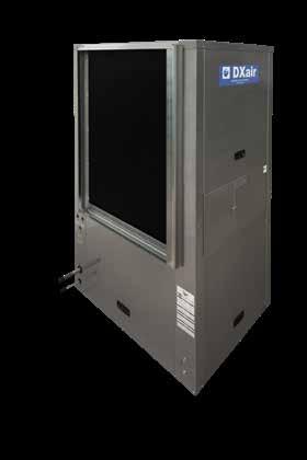
1 DXAIR Indoor Pool Dehumidification Systems Stainless Steel Series 2-20 Tons The perfect balance of water and air. (800)


2 TABLE OF CONTENTS DXair Stainless Steel Pool Dehumidifiers...3 DXair Models Available...4 Model Configuration...5 Standard Units...6 Performance Data...7 Electrical Data...8 Physical Data...9 Blower Curves...10 Installation Drawings...13 High and Ultra CFM Units...15 Overview...16 Performance Data...17 Physical Data...19 Electrical Data...20 Blower Curves...22 Installation Drawings...25 TAC Units...26 Performance Data...27 Physical Data...28 Electrical Data...29 Blower Curves...30 Installation Drawings...32 Guide Specifications...33 Example Air Delivery - Duct System Layout for all DXair Systems

3 DXAIR STAINLESS STEEL POOL DEHUMIDIFIERS DXair currently offers the industry s only complete line of high grade 304 Stainless Steel indoor pool dehumidification systems. One consolidated unit includes heating, cooling, dehumidification & pool heat recovery. These highly efficient units not only reduce operating costs, but contribute to reducing carbon dioxide emissions, a leading cause of global warming. Featuring: High Grade Stainless Steel cabinet Non-Reversing Geothermal based systems New TAC Models (Take Apart Construction, up to 20 tons that fit through a 36" doorway) Lowest industry refrigerant capacity (Green/LEED) Smallest footprint in the industry Many units can be built with high CFM capabilities ranging from 3000 CFM to 5000 CFM. Cleanable evaporator coils (no 6 or 8-row coils used) Copeland scroll compressors Specified optional for outdoor remote condensers RRS (reduced refrigeration systems) with fluid coolers Cupronickel heat exchangers for pool heating Non-ozone depleting R-410A refrigerant All panels removable for easy service Large blowers can be removed for smaller doorways and re-installation All air coils ElectroFin coated Bidirectional expansion valve Corrosion-proof, stainless steel drain pan ETL Certified to UL & CSA Standards Made in the USA Fault retry to eliminate nuisance service calls DXair exclusive MAX-evap included Extended unit warranty TO REQUEST A QUOTE, VISIT: dxair.com/request-a-quote 3
 Tonnage Standard")
4 SS SERIES MODELS AVAILABLE Standard Tonnage Standard Airflow CFM Optional Airflows, CFM High Ultra DVA N/A N/A DVA N/A DVA N/A DVA , 3200, 3600, DVA , 3200, 3600, DVA , DVA DVA N/A 5000 Take Apart Construction (TAC) Tonnage Standard Airflow CFM Optional Airflows, CFM High Ultra DVD , 6400, 7200, ,000 DVD , 6400, 7200, ,000 DVD , ,000 DVD N/A 10,000 N/A = Not Available 1 Units can be factory ordered at any of these settings or can be adjusted in the field. Additional models available. Contact DXair Sales for availability of models not listed. 4
 Single Stage=A Dual Compressor=D Nominal BTU (4,5,6) x 1000 Voltage (7) 208 / 230 V, 1ph=1 208 / 230 V. 3ph=2 460 / 480 V.")
5 MODEL CONFIGURATION DXair Model Configurator D V A R S N - L - X X - X X Model Number Digits DVA RSN-L-XX-XX Brand (1) DXair=D Unit Style (2) Vertical=V Hydronic=W CompressorType (3) Single Stage=A Dual Compressor=D Nominal BTU (4,5,6) x 1000 Voltage (7) 208 / 230 V, 1ph=1 208 / 230 V. 3ph=2 460 / 480 V. 3ph=3 Heat Exchanger (8) Fluid Cooler, Copper Coax=C Fluid Cooler, Cupronickel Coax=N Remote Condenser (supplied by others)=r Titanium (Load) & Copper (Source) Coax=T Reserved (14,15) XX=Reserved Miscellaneous Kits (12,13) *Any combination of two H=Heat Mode Kit T=Take Apart Construction X=None Return Airflow Configuration (11) L=Left Return (Standard) R=Right Return X=N/A Pool Heater (10) N=Cupronickel X=None CFM (9) A=Standard, Horizontal Supply B=Ultra CFM, Horizontal Supply C-Ultra CFM, Vertical Supply H=High CFM, Horizontal Supply S=Standard, Vertical Supply V=High CFM, Vertical Supply X=N/A 5

 6")
6 STANDARD UNITS STANDARD UNITS (2-10 TONS) 6

7 STANDARD UNITS PERFORMANCE DATA STANDARD UNITS (2-10 TONS) Cooling Performance - Fluid Cooler 1 Entering Water Temperature 59 F 77 F 86 F Model Fluid Flow GPM Airflow CFM DVA , , , DVA , , , DVA , , , DVA , , , DVA , , , DVA , , , DVA , , , DVA , , , Performance data was taken at noted water temperatures and return air conditions of 80.6 F Dry Bulb and 66.2 F Wet Bulb 2 3 Phase only Cooling Performance - Remote Condenser 1 Entering Air Temperature 70 F 80 F 90 F Model Fluid Flow GPM Airflow CFM DVA-024 N/A , , , DVA-041 N/A , , , DVA-053 N/A , , , DVA-061 N/A , , , DVA-073 N/A , , , DVA-097 N/A , , , DVA-110 N/A , , , DVA N/A , , , Performance data was taken at noted outside air temperatures and return air conditions of 80.6 F Dry Bulb and 66.2 F Wet Bulb 2 3 Phase only Dehumidification Performance Model Return Air Temp F Moisture Relative Humidity 50% RH lbs/h 60% RH lbs/h DVA DVA DVA DVA DVA DVA DVA DVA

8 STANDARD UNITS ELECTRICAL DATA STANDARD UNITS (2-10 TONS) Model Voltage Voltage Phase Hz Compressor Blower Total Min Max Fuse Code RLA LRA FLA FLA Ampac. HACR 1 208/ DVA / / / DVA / / / DVA / / / DVA / / / DVA / / / DVA / / / DVA / / DVA / /
9 STANDARD UNITS PHYSICAL DATA STANDARD UNITS (2-10 TONS) Model SS DVA-024 SS DVA-041 SS DVA-053 SS DVA-061 SS DVA-073 SS DVA-097 SS DVA-110 SS DVA-120 Compressor Nominal Tonnage Compressor Qty Compressor Type Scroll Scroll Scroll Scroll Scroll Scroll Scroll Scroll Max design pressure (psig) Blower and Motor Nominal CFM Nominal External Static Pressure (in H 2 O) Blower wheel size (dia x w) 9 x 9 9 x 9 9 x 9 10 x x x x x 11 Motor Type PSC PSC PSC PSC PSC CAP START CAP START CAP START Motor HP 1/3 1/2 1/ /2 1 1/2 1 1/2 Motor Speeds Drive Type Direct Direct Direct Direct Direct Belt Belt Belt Air Coils Coil Type Tube and Fin Tube and Fin Tube and Fin Tube and Fin Tube and Fin Tube and Fin Tube and Fin Tube and Fin Fin Spacing (fins/in) Coil Coating ElectroFin ElectroFin ElectroFin ElectroFin ElectroFin ElectroFin ElectroFin ElectroFin Evap Coil Dimensions (H" x W") 27 x x x x x x x x 25 Reheat Coil Dimensions (H" x W") 27 x x x x x x x x 25 Air Filter size (H" x W" x D") 29 x 28 x 1 29 x 28 x 1 29 x 28 x 1 38 x 28 x 1 38 x 28 x 1 38 x 28 x 1 38 x 28 x 1 38 x 28 x 1 FC, Fluid Cooler Option Hx Type Coaxial Tube in Tube Coaxial Tube in Tube Coaxial Tube in Tube Coaxial Tube in Tube Coaxial Tube in Tube Coaxial Tube in Tube Coaxial Tube in Tube Coaxial Tube in Tube Hx & Piping Liquid Volume (gal) Refrigeration Charge R410A (lbs/oz) 4/8 4/8 4/8 6/4 6/4 6/4 7/0 7/0 Min Flow (gpm) DX, Remote Condenser Heat Exchanger Hot Gas connection size (in) 7/8 7/8 7/8 7/8 7/8 7/8 7/8 7/8 Liquid connection size (in) 1/2 1/2 1/2 1/2 1/2 1/2 1/2 1/2 Hot Gas line 50ft max (in) Liquid line 50ft max (in) 1/2 1/2 5/8 5/8 5/8 3/4 7/8 7/8 3/8 3/8 1/2 1/2 1/2 1/2 5/8 5/8 Liquid connections, FNPT Source Loop Hx Condensate Drain 3/4 3/4 3/4 3/4 3/4 3/4 3/4 3/4 Pool Heater 1/2 1/2 1/2 1/2 1/2 1/2 1/2 1/2 Weight Shipping (lbs) Specifications subject to change. Shipping weights include the pallet and the box. Subtract 17 lbs for actual operating weight. When choosing the Remote Condenser option rather than the Fluid Cooler option, subtract 65 lbs. from shipping weight for actual operating weight. Note: Options will determine final operating weight. 9


10 STANDARD UNITS BLOWER CURVES DVA-024, 800CFM DVA-041, 1200 CFM 10

11 STANDARD UNITS BLOWER CURVES DVA-053, 1600 CFM DVA-061, 2000 CFM 11


12 STANDARD UNITS BLOWER CURVES DVA-073, 2400 CFM DVA-097, 3200 CFM 12

13 STANDARD UNITS BLOWER CURVES DVA-110, 3600 CFM DVA-120, 4000 CFM 13
14 STANDARD UNITS DXAIR SS SERIES DVA-024 TO 073 STANDARD CFM UNITS (2-10 TONS) Installed Dimensions Back Left Right Front Left Front Right Front Right Front Right 14
15 STANDARD UNITS DXAIR SS SERIES DVA-097 TO DVA-120 STANDARD CFM UNITS (8-10 TONS) Installed Dimensions Back Left Right Front Left Front Right NOTE: Blower can be removed for doorways and shipping Right Back Right Back 15


 16")
16 HIGH & ULTRA CFM UNITS HIGH & ULTRA CFM UNITS (3-20 TONS) 16
17 HIGH & ULTRA CFM UNITS OVERVIEW High CFM and Ultra CFM Models offer the same capacity as Standard models but with the added benefit of higher air flows and the ability to operate at higher static pressures. This allows for greater air exchanges per hour. In conjunction with these higher CFM models, the Max Evap Option will bypass the additional airflow in order to maintain the coldest possible evaporator coil and remove the highest amount of moisture. High and Ultra CFM options are offered on the following models: Standard CFM - Option A or S Total Airflow, CFM External Static Pressure (ESP), in WC DVA DVA DVA DVA DVA DVA DVA DVA DVD DVD DVD DVD High CFM - Option H or V DVA DVA DVA , 3200, 3600, DVA , 3200, 3600, DVA , DVA DVD , 6400, 7200, DVD , 6400, 7200, DVD , Ultra CFM - Option B or C DVA DVA DVA DVA DVD , DVD , DVD , DVD , Units can be factory ordered at any of these settings or can be adjusted in the field. 17

18 HIGH & ULTRA CFM UNITS PERFORMANCE DATA HIGH & ULTRA CFM UNITS (3-10 TONS) Cooling Performance - Fluid Cooler1 Entering Water Temperature 59 F 77 F 86 F Fluid Flow Airflow Model GPM CFM DVA , , , DVA , , , DVA , 3200, 3600, 4000, , , , DVA , 3200, 3600, 4000, , , , DVA , 4000, , , , DVA , , , , DVA , , , Performance data was taken at noted water temperatures and return air conditions of 80.6 F Dry Bulb and 66.2 F Wet Bulb. 2 3 Phase only Cooling Performance - Remote Condenser1 Entering Air Temperature 70 F 80 F 90 F Fluid Flow Airflow Model GPM CFM DVA-041 N/A , , , DVA-053 N/A , , , DVA-061 N/A 3000, 3200, 3600, 4000, , , , DVA-073 N/A 3000, 3200, 3600, 4000, , , , DVA-097 N/A 3600, 4000, , , , DVA-110 N/A 4000, , , , DVA N/A , , , Performance data was taken at noted outside air temperatures and return air conditions of 80.6 F Dry Bulb and 66.2 F Wet Bulb 2 3 Phase only Dehumidification Performance Model Return Air Temp F Moisture Relative Humidity 50% RH lbs/h 60% RH lbs/h DVA DVA DVA DVA DVA DVA DVA

19 HIGH & ULTRA CFM UNITS PERFORMANCE DATA (10-20 TONS) Cooling Performance - Fluid Cooler 1 Model Fluid Flow GPM DVD DVD Airflow CFM Fluid Cooler Entering Water Temperature 59 F 77 F 86 F 6000, 6400, 7200, 8000, 10, , , , , 6400, 7200, 8000, 10, , , , DVD , 8000, 10, , , , DVD , , , , Performance data was taken at noted water temperatures and return air conditions of 80.6 F Dry Bulb and 66.2 F Wet Bulb 2 3 Phase only HIGH & ULTRA CFM UNITS Cooling Performance - Remote Condenser 1 Remote Condenser Entering Air Temperature 70 F 80 F 90 F Model DVD-120 DVD-144 Fluid Flow GPM N/A N/A Airflow CFM 6000, 6400, 7200, 8000, 10, , , , , 6400, 7200, 8000, 10, , , , DVD-196 N/A 7200, 8000, 10, , , , DVD N/A 10, , , , Performance data was taken at noted outside air temperatures and return air conditions of 80.6 F Dry Bulb and 66.2 F Wet Bulb 2 3 Phase only Dehumidification Performance Model Return Air Temp F Moisture Relative Humidity 50% RH lbs/h 60% RH lbs/h DVD DVD DVD DVD
20 HIGH & ULTRA CFM UNITS PHYSICAL DATA - HIGH AND ULTRA CFM MODELS (3-20 TONS) High and Ultra CFM models utilize the same compressor, air coils, water connections, remote condenser connections, and other components as the Standard cfm models. Information regarding these components can be found in the Physical Data - Standard CFM Units section. Information on components that differ from Standard models is presented here. HIGH CFM OPTION Model DVA-041 DVA-053 DVA-061 DVA-073 DVA-097 DVA- 110 DVD-120 DVD-144 DVD-196 CFM Option Code V V H or V H or V H or V H or V H or V H or V H or V Nominal tonnage Blower and Motor CFM (factory or field adj) , 3200, , 3200, 3600, , , 6400, 7200, , 6400, 7200, , 8000 Blower wheel size (dia x w) 10 x x x x x x 11 (2x) 15 x 11 (2x) 15 x 11 (2x) 15 x 11 Motor Type PSC PSC Cap Start Cap Start Cap Start Cap Start Cap Start Cap Start Cap Start Motor HP /2 1 1/2 1 1/2 1 1/2 (2x) 1 1/2 (2x) 1 1/2 (2x) 1 1/2 Motor Speeds Drive Type Direct Direct Belt Belt Belt Belt Belt Belt Belt Weight Shipping (lbs) ULTRA CFM OPTION Model DVA-061 DVA-073 DVA-097 DVA-110 DVA-120 DVD-120 DVD-144 DVD-196 DVD-240 CFM Option Code B or C B or C B or C B or C B or C B or C B or C B or C B or C Nominal tonnage Blower and Motor CFM ,000 10,000 10,000 10,000 Blower wheel size (dia x w) 15 x x x x x 11 (2x) 15 x 11 (2x) 15 x 11 (2x) 15 x 11 (2x) 15 x 11 Motor Type 3 ph 3 ph 3 ph 3 ph 3 ph 3 ph 3 ph 3 ph 3 ph Motor HP (2x) 3 (2x) 3 (2x) 3 (2x) 3 Motor Speeds Drive Type Belt Belt Belt Belt Belt Belt Belt Belt Belt Weight Shipping (lbs)
21 HIGH & ULTRA CFM UNITS HIGH CFM ELECTRICAL DATA (3-16 TONS) Model Voltage Voltage Phase Hz Compressor Blower Total Min. Max Fuse Code RLA LRA FLA FLA Ampac. HACR High CFM 1 208/ DVA / / / DVA / / / DVA / / / DVA / / / DVA / / / DVA / / / DVD / / / DVD / / / DVD / /

22 SS SERIES SPECIFICATION GUIDELINES HIGH & ULTRA CFM UNITS ULTRA CFM ELECTRICAL DATA (5-20 TONS) 1 Model Voltage Voltage Phase Hz Compressor Blower Total Min. Max Fuse Ultra CFM 1 Code RLA LRA FLA FLA Ampac. HACR DVA-061 DVA-073 DVA-097 DVA-110 DVA / / / / / / / / / / DVD-120 DVD-144 DVD-196 DVD / / / / / / / / Ultra CFM units are only available as 3 phase units. 22

23 HIGH & ULTRA CFM UNITS BLOWER CURVES DVA-041, 1400 CFM DVA-053, 2000 CFM 23


24 HIGH & ULTRA CFM UNITS BLOWER CURVES DVA-061, -073, 3000 CFM DVA-061, -073, 3200 CFM 24


25 HIGH & ULTRA CFM UNITS BLOWER CURVES DVA-061, -073, -097, -110, 4000 CFM DVA-061 to -120, 5000 CFM and DVD-120 to -240: 10,000 CFM 1 1 DVD units utilize two (2) 15 x 11 blowers operating in parallel for 2x flow and require the same ESP for each blower. 25
26 HIGH & ULTRA CFM UNITS DXAIR SS SERIES DVA-061 to 120, HIGH CFM OPTION (5-10 TONS) Installed Dimensions Back Left Right Front Left Front Right Larger Blower Package Right Back Right Back 26


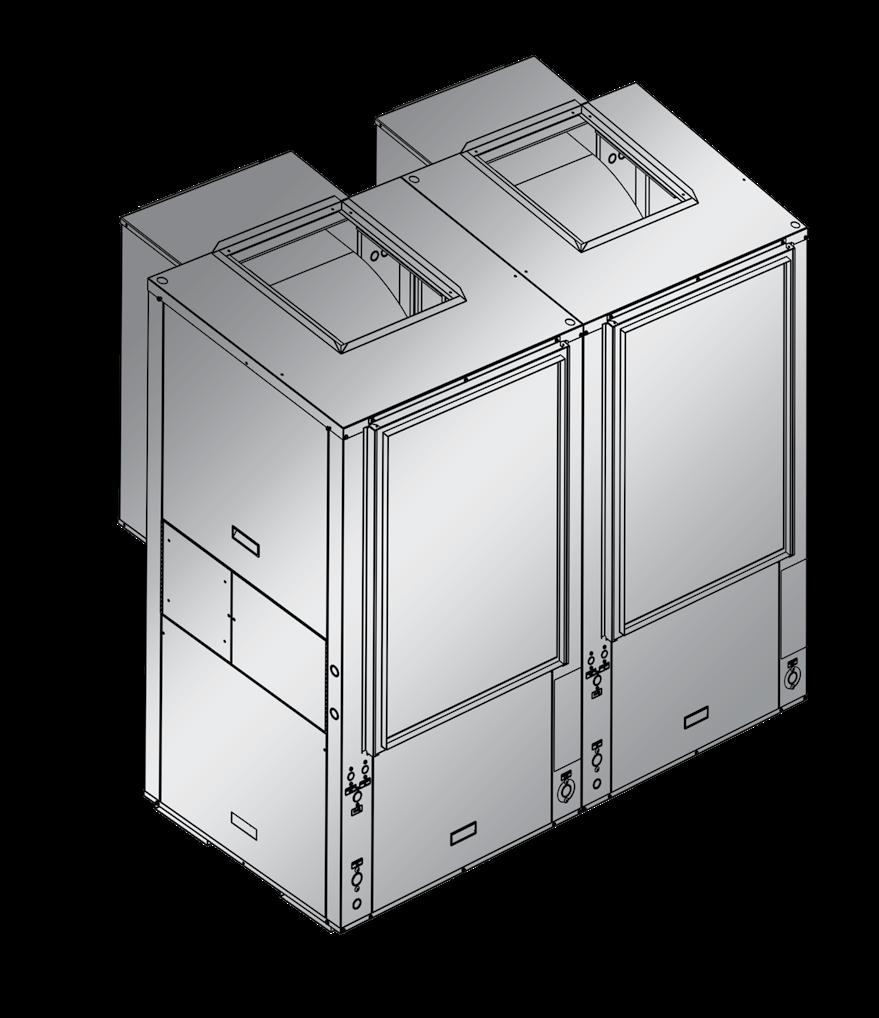

27 TAC UNITS TAKE APART CONSTRUCTION (TAC) UNITS (10-20 TONS) 27

28 TAC UNITS TAKE APART CONSTRUCTION (TAC) UNITS (10-20 TONS) TAC units offer increased capacity in a modular footprint that makes them easy to move into spaces with limited entry ways. TAC PERFORMANCE DATA Cooling Performance - Fluid Cooler 1 Fluid Cooler Entering Water Temperature 59 F 77 F 86 F Model Fluid Flow GPM Airflow CFM DVD , , , DVD , , , DVD , , , DVD , , , Performance data was taken at noted water temperatures and return air conditions of 80.6 F Dry Bulb and 66.2 F Wet Bulb 2 3 Phase only Cooling Performance - Remote Condenser 1 Remote Condenser Entering Air Temperature 70 F 80 F 90 F Model Fluid Flow GPM Airflow CFM DVD-120 N/A , , , DVD-144 N/A , , , DVD-196 N/A , , , DVD N/A , , , Performance data was taken at noted outside air temperatures and return air conditions of 80.6 F Dry Bulb and 66.2 F Wet Bulb 2 3 Phase only Dehumidification Performance Model Return Air Temp F Moisture Relative Humidity 50% RH lbs/h 60% RH lbs/h DVD DVD DVD DVD
29 TAC UNITS PHYSICAL DATA - TAC UNITS (10-20 TONS) Model SS DVD-120 SS DVD-144 SS DVD-196 SS DVD-240 Compressor Nominal Tonnage Compressor Qty Compressor Type Scroll Scroll Scroll Scroll Max design pressure (psig) Blower and Motor Nominal CFM Nominal External Static Pressure (in H 2 O) Blower wheel size (dia x w) 10 x x x x 11 Motor Type PSC PSC Cap Start Cap Start Motor HP /2 1 1/2 Motor Speeds Drive Type Direct Direct Belt Belt Air Coils Coil Type Tube and Fin Tube and Fin Tube and Fin Tube and Fin Fin Spacing (fins/in) Coil Coating ElectroFin ElectroFin ElectroFin ElectroFin Evap Coil Dimensions (H x W ) (x2) 36 x x x x 25 Reheat Coil Dimensions (H x W ) (x2) 36 x x x x 25 Air Filter size (H x W x D ) (x2) 38 x 28 x 1 38 x 28 x 1 38 x 28 x 1 38 x 28 x 1 FC, Fluid Cooler Option Hx Type Coaxial Coaxial Coaxial Coaxial Hx & Piping Water Volume (gal) Refrigeration Charge R410A (lbs/oz)/circuit 6 / 4 6 / 4 6 / 4 7 / 0 Min Flow (gpm) (1/2 each coil) DX, Remote DX Condenser Option Hot Gas connection size (in) (x2) 7/8 7/8 7/8 7/8 Liquid connection size (in) (x2) 1/2 1/2 1/2 1/2 Hot Gas line 50ft max (in) 5/8 5/8 3/4 7/8 Liquid line 50ft max (in) 1/2 1/2 1/2 5/8 Water connections, FNPT Source Loop Hx Condensate Drain 3/4 3/4 3/4 3/4 Pool Heater 1/2 1/2 1/2 1/2 Weight Shipping (lbs) Specifications subject to change. 29

30 SS SERIES SPECIFICATION GUIDELINES TAC UNITS TAC ELECTRICAL Model Voltage Voltage Phase Hz Compressor Blower Total Min. Max Fuse Code RLA LRA FLA FLA Ampac. HACR 1 208/ DVD / / / DVD / / / DVD / / DVD / /

 31")
31 TAC UNITS BLOWER CURVES DVD-120, 4000 CFM 1 1 DVD units utilize two (2) blowers operating in parallel for 2x flow and require the same ESP for each blower. DVD-144: 4800 CFM 1 1 DVD units utilize two (2) blowers operating in parallel for 2x flow and require the same ESP for each blower. 31

 32")
32 TAC UNITS BLOWER CURVES DVD-196: 6400 CFM 1 1 DVD units utilize two (2) blowers operating in parallel for 2x flow and require the same ESP for each blower. DVD-240: 8000 CFM 1 1 DVD units utilize two (2) blowers operating in parallel for 2x flow and require the same ESP for each blower. 32
33 TAC UNITS DXAIR SS SERIES DVD-120 TO DVA-240 TAC UNITS (10-20 TONS) Installed dimensions 33
34 GUIDE SPECIFICATIONS 1.0 General Furnish and install as indicated on the plans with capacities and characteristics as listed in the schedule and the specifications that follow. 2.0 Fluid Cooled The units shall be designed to operate with entering fluid temperatures between 50 F (10 C) and 100 F (38 C) in cooling Basic Construction A. Units shall have the air flow arrangement as shown on the plans. If units with these arrangements are not used, the contractor supplying the unit is responsible for any extra costs incurred by other trades and must submit detailed mechanical drawings showing ductwork requirements and changes or relocation of any other mechanical or electrical system. If other arrangements make servicing difficult, the contractor must provide access panels and clear routes to ease service. The architect must approve all changes 10 days prior to bid. B. All units shall have stainless steel drain pans to comply with this project s IAQ requirements. Painted steel or plastic is not acceptable. C. The cabinet shall be fabricated from 18 ga. 304 series stainless steel for superior corrosion protection. 34 All interior surfaces shall be lined with 1/2 inch thick, 1.5 lb. / density, Micromat insulation for thermal protection and acoustical attenuation. All insulation must meet NFPA 90A and 90B for fire protection and shall be certified to meet the GREENGUARD Indoor Air Quality Standard for Low Emitting Products. One blower access panel and two compressor compartment access panels shall be removable with supply and return air ductwork in place. D. Units shall have a suspended compressor with dual physical isolation. This shall consist of mounting the compressor to a heavy-gauge mounting plate with engineered vibration isolation grommets. This sub assembly shall then be attached to the base of the cabinet with additional engineered vibration isolation grommets for enhanced sound and vibration dampening. The compressor shall be located in an insulated compartment physically separated from the air stream to further reduce sound transmission. E. Units shall have a washable 1-inch thick electrostatic return filter as standard. The filter rack shall incorporate a 3/4-inch duct flange to eliminate the need for a field installed duct collar. The units shall have an insulated divider panel between the air handling section and the compressor section to minimize the transmission of compressor noise and to permit service testing without air bypass. F. Cabinets shall have separate holes and knockouts for entrance of line voltage and low voltage control wiring. Supply and return liquid connections shall be 1-inch NPT brass female pipe thread fittings and mounted flush to cabinet exterior. Connections that require a backup wrench or extrude past the unit corner post are not acceptable. Condensate connections shall be 3/4-inch NPT brass female pipe thread fittings and mounted flush to cabinet exterior. G. Evaporator Coils: All units shall have evaporator coils with a maximum of 4 refrigerant lines aligned perpendicular to the return airflow. Evaporator coils with more than 4 refrigerant lines are not allowed Fan and Motor Assembly The fan motor shall be a 3-speed, permanently lubricated, Permanent Split (PSC) type with thermal overload protection. The motor shall have the capability to be wired for low, medium, and high speed. A. The fan shall be direct-drive or belt driven centrifugal forward curved type with a dynamically balanced wheel. The housing and wheel shall be designed for quiet low velocity operation. Direct-drive or belt driven fan is dependent on unit capacity and/or optional equipment.
35 2.03 Refrigerant Circuit Units shall use R-410A refrigerant. All units shall have a factory sealed and fully charged refrigerant circuit with the following components: A. Compressors shall be hermetic motor scroll compressors specifically designed for R-410A refrigerant and shall be internally sprung, be externally isolated, and shall have integral internal thermal overload protection. B. Refrigerant metering shall be performed by balancedport thermal expansion valves with external equalizer. C. Two finned air coil heat exchangers constructed of lanced and rippled aluminum fins not exceeding sixteen fins per inch bonded to rifled copper tubes in a staggered pattern. Air coils shall have a 600 PSIG (4140 kpa) minimum working pressure. One air coil shall be the evaporator. The other air coil shall be the condenser for the full dehumidification mode and shall be inactive in the full cooling mode. Air coils shall have an ElectroFin coating to protect against salt air and other corrosive and chemical environments. This does not negate maintaining proper pool chemistry at all times. D. Cooling Diverting Valves shall be 4-way solenoid activated refrigerant valves which shall fail safe to the full dehumidification mode should the solenoid fail to function. Valves which fail to the cooling operation mode shall not be allowed. E. Liquid-cooled condenser heat exchanger shall be a coaxial (tube in tube) refrigerant to liquid heat exchanger. This exchanger shall be the condenser in the full cooling mode and shall be inactive in the full dehumidification mode. It shall be of copper inner liquid tube and steel outer refrigerant tube design rated to withstand 600 PSIG minimum working refrigerant pressure and 400 PSIG minimum working liquid pressure. The manufacturer will offer as a factory option a Cupro-Nickel liquid coil. The liquid tube of this optional refrigerant to liquid heat exchanger shall have cupronickel liner. F. Pool Heater coaxial (tube in tube) refrigerant to liquid heat exchanger shall be standard. It shall be of copper inner liquid tube and steel outer refrigerant tube design rated to withstand 600 PSIG minimum working refrigerant pressure and 300 PSIG minimum working liquid pressure. The manufacturer shall offer as a factory option a Cupro-Nickel pool heater coil. The liquid tube of this optional refrigerant to liquid heat exchanger shall have a cupronickel liner. G. Safety controls shall include both a high pressure and low pressure switch. 1. Low pressure cutout set at 40 PSIG (280 kpa) for loss of charge protection. 2. High pressure cutout set at 600 PSIG (4125 kpa). Temperature sensors shall not be used as safety controls. H. Access fittings shall be factory installed on high and low pressure refrigerant lines to facilitate field service. I. Activation of any safety device shall prevent compressor operation via a lockout circuit. The lockout circuit shall only be reset by interrupting power at the contractor-supplied disconnect switch. Units which may be reset via thermostat controls shall not be acceptable. Refer to subsequent Solid State Lockout Controller section for additional requirements Electrical Controls and safety devices shall be factory wired and mounted within the unit. Controls shall include blower relay, compressor contactor, 24Vac transformer, mode-change relay and dual-function timer, diverting valve coil, and Solid State Lockout Controller (SSLC). The standard transformer shall be rated for a minimum 100 VA and shall have a push button reset circuit breaker on the secondary power. All units shall be name-plated for use with time delay fuses or HACR circuit breakers. Unit controls shall be 24Vac. 24Vac control connections shall be labeled by function code to allow for ease of field wiring. Field wiring of supply voltage shall be directly to the compressor contactor. The electrical control system function codes are as follows: 35
36 1. H = Dehumidification mode. 2. Y = Cooling mode. 3. G = Blower. 4. R = 24Vac power 5. F = Fault, 24Vac output, 0.50amp maximum 6. P = Pump output, 24Vac, 0.25amp maximum 7. D = Damper output, 24Vac, 0.25amp maximum 8. C = Common, chassis ground. 9. W = Heat mode (optional) The electrical control system provides the following functions: Function Dehumidification mode Cooling Mode Heat Mode (optional) Blower only Control Connections R connected to H R connected to Y R connected to W R connected to G Comment Fault indication F F is energized whenever the SSLC is in lockout. Pump output P Energized when unit is in the Cooling or Heat modes. De-energized when unit is in Dehumidification mode. Damper output D Energized when unit is in Dehumidification mode. Notes: 1. Cooling mode has priority over dehumidification mode. A dual-function timer and the mode-change relay work together to allow the SSLC to provide anti-short cycle delay times between mode transitions. 2. Blower operates continuously with R connected to G. Blower also operates continuously in Dehumidification, Cooling, or Heat modes Solid-State Lockout Controller (SSLC) All units shall have a Solid State Lockout Controller with the following features: 1. Random start time delay on initial power. 2. Anti-short cycle time delay (5 minute delay on break). 3. High refrigerant pressure lockout. 4. Low refrigerant pressure lockout VAC alarm output for remote fault indication. 6. Test mode (reduces all time delays to 5 seconds for diagnostic work). 7. Lockout reset on power reset. The SSLC will begin the 5-minute anti-short cycle time delay after a Y call ends, after a H call ends, after transition from cooling to dehumidification, or after transition from dehumidification to cooling. After the time delay, the contactor will energize as long as the high and low pressure switches are closed along with a Y or H call. If either switch is open after the delay, the contactor will not energize. If either switch opens while the contactor is energized, the contactor will de-energize immediately, and SSLC will begin the anti-short cycle delay. The contactor will not be allowed to energize again until the anti-short cycle delay and both pressure switches are closed. If SSLC has three high pressure or low pressure switch faults in a 60-minute period, it will lock out the contactor and energize the fault output. A manual reset of power will be required to reset the lockout condition. The SSLC has a status LED to indicate which type of fault or lockout has occurred. If a high pressure fault or lockout occurs, the status LED will blink once. If a low pressure fault or lockout occurs, the status LED will blink twice. 36
37 2.06 Installation and Operation Considerations A. Condensate Drain Piping Condensate piping can be made of steel, copper or PVC pipe. In most cases, PVC Pipe eliminates the need to wrap insulation around the pipe to prevent sweating. A ¾ FPT condensate drain connection is installed in the unit. The condensate piping must be trapped at the unit and pitched away from the unit not less than ¼ per foot. A vent is required after the trap so that the condensate will drain away from the unit. This vent can also act as a clean out if the trap becomes clogged. The condensate drain should NOT be directly piped to a drain/waste/vent stack. Check your own local codes for correct application of condensate piping to drains. B. Low Temperature Well Water When low temperature well water (LIQUID COOLED SYSTEM) is utilized as the liquid source (below 55 Degrees F), a means of establishing two flow rates, one for the cooling/reheat mode and one for the heating mode is recommended. IN the cooling mode at low entering liquid temperatures and standard flow rates, discharge pressures and corresponding discharge gas temperatures are relatively low. At these conditions when the reheat mode is initiated, the lower temperature discharge gas can reduce reheat capacity. A means to reduce the liquid flow rate and elevate the discharge pressure/temperature in cooling/ reheat mode should be provided. The simplest way to accomplish the above is to install liquid modulating valves. C. Serviceability All units are designed to be serviced from the front of the unit. Schrader vales for high and low pressure gauges and the electrical box components are easily accessible for diagnosing and servicing the unit. Insulated bulkheads in all units, separate the compressor section from the blower section, allowing the unit to be serviced during operation. Do not install units in any unconditioned space, crawl spaces, under the pool, closets, garages, above ceilings, attic spaces, spaces accessed by a trap door or limited access. These units must be checked and serviced on a regular basis; installing them in areas where they are not accessible to the end user and preventive maintenance leads to problems with service and maintenance. Separate electrical knockouts in the unit corner post allow for easy and safe routing of high and low voltage lines to the inside of the cabinet. D. Unit Location DO NOT STORE Pool equipment and/or pool chemicals in the mechanical space designed for the DXAir Dehumidification System. Failure to follow these instructions may void your warranty as chemicals are highly corrosive and destructive to any HVAC system. Any mechanical device will, at some point in time, require servicing and repair. With this in mind, sufficient mechanical space must be designed and sufficient clearances around each horizontal and vertical unit must be provided clearance is required around the unit and access panels. Proper clearances for installation of peripherals and space must be allowed for the proper duct work installation. Choking down ductwork in this mechanical space will have negative air flow effects for your pool room. Sufficient space must be provided for filter replacement and access to the compressors. Units should be set on a piece of rubber,neoprene or other vibration absorbing material at least 1/3- ½ thick. The pad should extend ¾ over the entire base of the unit. Avoid direct line of sight to the unit. Install a sound baffle over any door that has a return air grille. E. Sound Sound is becoming an increasingly important factor in all HVAC Installations. Most of the problems associated with HVAC generated noise can be avoided by paying close attention to the equipment placement in properly designed mechanical space and the duct work/air delivery system. F. Duct Work/Air Delivery System DXair requires a very high standard of duct system for all our systems. All specifications for the air delivery system 37


38 must be met. All ASHRAE and ACCA Manuals pertaining to properly designed and sized duct work must be followed as well. Proper air delivery design and air turnover rates are critical to maintaining the required temperatures and relative humidity within the environment. Overhead or underground ducting can be used. A continuous loop of duct work is recommended at a.20 static on supply and.07 on one high return air. High supply, low return, low supply high return is recommended in all installations. All diffusers should be double deflection linear diffusers and must move proper air flow to all glass/skylights and other surfaces that are prone to reaching Dew Point Temperature when the outdoor temperature falls below indoor pool room temperature. Diffusers are not designed to "blow down" across an open pool, nor are they to be installed in walls between windows blowing across an open pool. All diffusers must be deflected at the glass areas to prevent condensation. Where duct work cannot prevent stratification, ceiling fans blowing up are recommended. All skylights must be addressed with air flow via duct work or ceiling fans blowing up. No Fiberboard or flex duct should be used in the air delivery system unless approved in writing by DXair engineering. EXAMPLE AIR DELIVERY DUCT SYSTEM LAYOUT FOR ALL DXAIR SYSTEMS Supply Duct Required to allow for Air Flow over All Glazed Areas POOL ROOM DEHUMIDIFICATION SYSTEM Typical Pool Layout Pool Water Return Line DXair Continuous Loop Supply Air Turning Vanes Auxiliary Heat Electric Gas/Propane Hot Water Coil High Return Air Mechanical Space DXair Dehumidifier Canvas /Rubber Duct Isolation Check or manual diverting valve to waste heat to pool water Pool Filter NOTE: Example Drawing only not to scale. This example is underground ducting with a high return air. Overhead ducting would utilize a low return air. Note all diffusers are deflected at all glass surfaces to move warm air and prevent condensation. DXAir will provide engineering and shop drawings for the air delivery system for your project. 38


39 DXair SS Series Guide Specifications DXAir Phone: Fax: Revised Copyright 2018 DXair. All rights reserved. Subject to change, addition, deletion, obsolesce or upgrades at any time.
GTIP60 ISO GT Series, Inch Pounds - 60 Hz GT (iso) Spec Guide Drawings Spec Sheets Low Temp Heating P/T Charts
 Spec Guide Drawings Spec Sheets Low Temp Heating P/T Charts") GTIP60 ISO GT Series, Inch Pounds 60 Hz GT010070 (iso) Spec Guide Drawings Spec Sheets Low Temp Heating P/T Charts Rev: 903 Rev 1 Revisions: 31103 Changed HZ dwg to field convertible 5902 changed Unit
GTIP60 ISO GT Series, Inch Pounds 60 Hz GT010070 (iso) Spec Guide Drawings Spec Sheets Low Temp Heating P/T Charts Rev: 903 Rev 1 Revisions: 31103 Changed HZ dwg to field convertible 5902 changed Unit
GUIDE SPECIFICATIONS AQUARIUS ii
 Catalog (AP Technical Data Sheet) GUIDE SPECIFICATIONS AQUARIUS ii AP Series Two Stage R-410A GENERAL Units shall be performance certified to ISO standard 13256-1 for Water Loop Heat Pump, Ground Water
GUIDE SPECIFICATIONS AQUARIUS ii
 Catalog (AP Technical Data Sheet) GUIDE SPECIFICATIONS AQUARIUS ii AP Series Two Stage R-410A GENERAL Units shall be performance certified to ISO standard 13256-1 for Water Loop Pump, Ground Water Pump
Greensource Residential Water Source Heat Pumps. Simply Smart. i Series: SV Model. boschheatingandcooling.com
 Greensource Residential Water Source Heat Pumps i Series: SV Model Simply Smart The i Series SV Model is a cost-effective single stage water source heat pump that is designed for commercial retrofit and
DXair Pool Dehumidifiers
 DXair Pool Dehumidifiers LV Series / to 6 Ton G-60 Galvanized The option-rich DXair LV Series pool dehumidifier has one of the smallest cabinets in the industry, making it a great choice for replacement
ENGINEERING GUIDE. Water-Cooled Self-Contained Units C-Series, Vertical
 ENGINEERING GUIDE Water-Cooled Self-Contained Units C-Series, Vertical TABLE OF CONTENTS Introduction...2 Product Overview...3 Nomenclature...4 General Data...5 Cooling Performance Data....6 Evaporator
Advance Release September 2009
 Vertical Air Cooled DSV Series R 410A Model DSV096 DSV120 DSV144 DSV180 Nominal Cooling (Tons) 8 10 12 15 Refrigerant R 410A R 410A R 410A R 410A Cooling Performance Gross Cooling Capacity(Btu/h) 95,000*
MACH N-407 Heat Pump Air-Cooled Chiller
 MACH060-01-N-407 Heat Pump Air-Cooled Chiller Heat Pump Air-Cooled Chillers for Global Residential and Light Commercial Microclimates MACH NOMENCLATURE BREAKDOWN MACH-060-01 - N - 407 Refrigerant Type
DSV Model Air Cooled Self Contained Indoor Packaged Units 3-5 Tons Preliminary Application Data
 DSV Model Air Cooled Self Contained Indoor Packaged Units 3-5 Tons Preliminary Application Data July 28, 2008 Page 1 1 of 3 PROJECT: TAG: Gross Cooling Capacity [Btuh]: 37,800* Design CFM: 1,200 Seasonal
GUIDE SPECIFICATIONS. WW Series Water-to-Water Reverse Cycle Chillers & Low Temp Boilers. WW Reverse Cycle Chillers / Low Temperature Boilers
 GUIDE SPECIFICATIONS WW Series Water-to-Water Reverse Cycle Chillers & Low Temp Boilers WW024-072 Reverse Cycle Chillers / Low Temperature Boilers GENERAL Units shall be Underwriter Laboratories (UL) listed
MAC N-407 Air-Cooled Chiller
 MAC036-01-N-407 Air-Cooled Chiller Air-Cooled Chillers for Global Residential and Light Commercial MicroClimates MAC036 NOMENCLATURE BREAKDOWN MAC036-01 - N - 407 Refrigerant Type Air-Cooled Chiller 036=
Greensource iseries Water Source Heat Pumps. SV Model. Made in Florida boschheatingandcooling.com
 boschheatingandcooling.com 1 Greensource iseries Water Source Heat Pumps SV Model Made in Florida boschheatingandcooling.com 1 Replacement Water Source Heat Pump About the Bosch Group The Bosch Group has
TECHNICAL GUIDE DESCRIPTION SPLIT-SYSTEM AIR-COOLED CONDENSING UNITS MODELS: HF-07 FEATURES B-0703
 TECHNICAL GUIDE SPLIT-SYSTEM AIR-COOLED CONDENSING UNITS MODELS: HF-07 DESCRIPTION These Sunline 2000 units are completely assembled, piped and wired at the factory to provide one-piece shipment and rigging.
technical guide Water-Cooled Self-Contained Units
 technical guide Water-Cooled Self-Contained Units C-Series, Vertical Technical Guide: YK145.00-EG3 (710) TABLE OF CONTENTS Water-Cooled Self-Contained Units Introduction...............................................................................
MIN. CCT. QTY RLA LRA HP FLA AMPACITY /1/ /3/
 1 of 3 Cooling Capacity [Btuh] 24,800 * Condensing Unit SEER: 13.0 ** Condensing Unit CFM: 1,600 Condenser Fan No./Type: 1/CENTRIFUGAL Diameter x Width [in]: 10x10 Drive: Adjustable Belt Motor HP: 0.5
water to water heat pumps
 AQUARIUS WW SERIES water to water heat pumps O ur Aquarius WW Series water-cooled modular reverse cycle chillers are designed to meet all your replacement or new construction chiller requirements. Specifically
MHNCCX DX with Hot Water Heat Ceiling Concealed 4-Pipe Heat / Cool Fan Coil 12,000-36,000 BTUH
 MHNCCX DX with Hot Water Heat Ceiling Concealed 4-Pipe Heat / Cool Fan Coil 12,000-36,000 BTUH 318 MHNCCX NOMENCLATURE BREAKDOWN 4-Pipe Heat/Cool Ceiling Concealed Fan Coil MHNCCW- XX - XX Ceiling Concealed
MAC-036HE-02-L High Efficiency Air-Cooled Chiller Air-Cooled Chillers for Global Residential and Light Commercial Micro Climates Rev 1.
 MAC-036HE-02-L High Efficiency Air-Cooled Chiller Air-Cooled Chillers for Global Residential and Light Commercial Micro Climates Rev 1.1 HVAC Guide Specifications Air-Cooled Liquid Chiller with Low Ambient
MAC-048HE-01-L High Efficiency Air-Cooled Chiller Air-Cooled Chillers for Global Residential and Light Commercial Micro Climates Rev 1.
 MAC-048HE-01-L High Efficiency Air-Cooled Chiller Air-Cooled Chillers for Global Residential and Light Commercial Micro Climates Rev 1.1 HVAC Guide Specifications Air-Cooled Liquid Chiller with Low Ambient
Indoor Air Handlers with Compressors MVS and MVW
 Indoor Air Handlers with Compressors MVS60-90-120-144 and MVW60-90-120-144 General Description The Marvair Marine self-contained water and air cooled air conditioners are designed for both new installations
MAC-060HE-01-L High Efficiency Air-Cooled Chiller Air-Cooled Chillers for Global Residential and Light Commercial Micro Climates Rev 1.
 MAC-060HE-01-L High Efficiency Air-Cooled Chiller Air-Cooled Chillers for Global Residential and Light Commercial Micro Climates Rev 1.2 HVAC Guide Specifications Air-Cooled Liquid Chiller with Low Ambient
TECHNICAL GUIDE SPLIT-SYSTEM AIR-COOLED EVAPORATOR BLOWER 25, 30, 40 & 50 TON LA300, LB360, 480 & 600 (50 Hz) PROVEN PERFORMANCE GENERAL FEATURING
 PROVEN PERFORMANCE GENERAL FEATURING") TECHNICAL GUIDE SPLIT-SYSTEM AIR-COOLED EVAPORATOR BLOWER 25, 30, 40 & 50 TON LA300, LB360, 480 & 600 (50 Hz) PROVEN PERFORMANCE GENERAL The LA/LB line is a flexible performer. LA300, LB360 & 480 can be
TECHNICAL GUIDE SPLIT-SYSTEM AIR-COOLED EVAPORATOR BLOWER 25, 30, 40 & 50 TON LA300, LB360, 480 & 600 (50 Hz) PROVEN PERFORMANCE GENERAL The LA/LB line is a flexible performer. LA300, LB360 & 480 can be
EMBASSY SERIES SINGLE PACKAGE AIR CONDITIONERS (WATER-COOLED) C2ED060, 090, 120 & 180 5, 7-1/2, 10 & 15 Nominal Tons
 C2ED060, 090, 120 & 180 5, 7-1/2, 10 & 15 Nominal Tons") 560.20-TG1Y (388) EMBASSY SERIES SINGLE PACKAGE AIR CONDITIONERS (WATER-COOLED) C2ED060, 090, 120 & 180 5, 7-1/2, 10 & 15 Nominal Tons Each circuit includes a fully hermetic compressor with a crankcase
560.20-TG1Y (388) EMBASSY SERIES SINGLE PACKAGE AIR CONDITIONERS (WATER-COOLED) C2ED060, 090, 120 & 180 5, 7-1/2, 10 & 15 Nominal Tons Each circuit includes a fully hermetic compressor with a crankcase
B. Unit construction shall comply with ASHRAE 15 Safety Code, NEC, and ASME applicable codes (U.S.A. codes).
.") Guide Specifications PART 1 GENERAL 1.01 SYSTEM DESCRIPTION Microprocessor controlled, air-cooled liquid chiller utilizing scroll compressors, low sound fans, hydronic pump system and optional fluid storage
Guide Specifications PART 1 GENERAL 1.01 SYSTEM DESCRIPTION Microprocessor controlled, air-cooled liquid chiller utilizing scroll compressors, low sound fans, hydronic pump system and optional fluid storage
Product Data. Features/Benefits. OMNIZONE 50BV Remote Air-Cooled and Water-Cooled Indoor Self-Contained Systems and Water Source Heat Pumps
 Product Data OMNIZONE 50BV020-064 Remote Air-Cooled and Water-Cooled Indoor Self-Contained Systems and Water Source Heat Pumps 18 to 60 Nominal Tons omnizonebwlogo 50BVC,E,J,K,Q020-034 SINGLE PIECE OMNIZONE
MAC-120HE-03 Air-Cooled Chiller
 MAC-120HE-03 Air-Cooled Chiller 10 Ton / 120,000 BTUH Air-Cooled Chiller 380/415/460-3-50/60 1 HVAC Guide Specifications Air-Cooled Liquid Chiller Nominal Size: 10 Tons Multiaqua Model Number: MAC-120HE-03
Compact, Self-Contained unit that offer low installation cost plus dependable performance.
 0 Compact, Self-Contained unit that offer low installation cost plus dependable performance. From carrier s excellence in engineering come a new, compact of single package horizontal and vertical water
Water-Cooled Self-Contained Units
 CATALOG FORM SK145.15-EG1 (1017) Water-Cooled Self-Contained Units C-Series, Vertical Nomenclature WATER-COOLED SELF-CONTAINED UNIT 1, 2 3 4, 5, 6 7 8 9 10 11 12 13 14 15 16 17 CS V 180 B 2 M 1 V A A A
SECTION WATER-SOURCE UNITARY HEAT PUMPS
 SECTION 23 81 46 PART 1 - GENERAL 1.1 DESCRIPTION SPEC WRITER NOTES: 1. Use this section only for NCA projects. 2. Delete between // // if not applicable to project. Also delete any other item or paragraph
VERTICAL STACK INNKEEPER GUIDE SPECIFICATION CGC Hybrid Heat Pump System
 VERTICAL STACK INNKEEPER GUIDE SPECIFICATION CGC Hybrid Heat Pump System PART 1 SYSTEM DESCRIPTION 1.1 The HVAC system is based on the CGC HYBRID Hydronic Heat Pump System. 1.2 The system will automatically
VertiCool Aurora Engineering Guide
 Engineering Guide Effective August 2016 Air-Cooled, Water-Cooled and Water Source Heat Pump Contents Product Features... 3 Options... 4 Physical Data...5-6 Air-Cooled Performance Data (a) (b) (c)...7-8
TECHNICAL GUIDE. Description SPLIT-SYSTEM AIR-COOLED CONDENSING UNITS YD360, 480 & THRU 50 NOMINAL TONS YTG-B-0811
 Description These units are completely assembled, piped and wired at the factory to provide one-piece shipment and rigging. Each unit is pressurized with a holding charge of Refrigerant R-410A for storage
Commercial High-Efficiency Condensing Units
 FORM NO. A22-194 REV. 2 Supersedes Form No. A22-194 Rev. 1 Commercial High-Efficiency Condensing Units RAWL High Efficiency 6.5 & 7.5 TON MODEL [22.86 & 26.38 kw] TABLE OF CONTENTS Model Number Designation...2
MHCCW Chilled Water Ceiling Concealed With 5kW Electric Heat 2-Pipe Heat / Cool Fan Coil 30,000 BTUH
 MHCCW-10-05 Chilled Water Ceiling Concealed With 5kW Electric Heat 2-Pipe Heat / Cool Fan Coil 30,000 BTUH Rev. 1.21 HVAC Guide Specifications Chilled Water Fan Coil with Electric Heat 2-Pipe Nominal Size:
MHCCW Chilled Water Ceiling Concealed Without Electric Heat 2-Pipe Heat / Cool Fan Coil 18,000 BTUH
 MHCCW-06-00 Chilled Water Ceiling Concealed Without Electric Heat 2-Pipe Heat / Cool Fan Coil 18,000 BTUH Rev. 1.21 HVAC Guide Specifications Chilled or Hot Water Fan Coil 2-Pipe Nominal Size: 18,000 BTUH
Technical Development Program COMMERCIAL HVAC SYSTEMS. Water Source Heat Pump Systems PRESENTED BY: Ray Chow. Sales Engineer
 Technical Development Program PRESENTED BY: COMMERCIAL HVAC SYSTEMS Water Source Heat Pump Systems Ray Chow Sales Engineer TDP Updates Menu Section 1 Section 2 Section 3 Section 4 Section 5 Section 6 Section
ENGINEERING SPECIFICATIONS
 ENGINEERING SPECIFICATIONS RH-24-HAC-P-1L-C-SDE*F Horizontal Single Stage R410a Model Size 24 Reversing (Heating AND Cooling) 208/230-1-60VAC Liquid to Air Geothermal Heat Pumps Maritime Geothermal Ltd.
VariCool VAV Engineering Guide
 Engineering Guide Effective September 2017 Water-Cooled and Chilled Water, Variable Air Volume Contents Product Features... 3 UNIT FEATURES... 3 Product Features... 4 Marvel Plus Microprocessor Control
ENGINEERING SPECIFICATIONS
 ENGINEERING SPECIFICATIONS RH-12-HAC-P-1L-C-SDE*F Horizontal Single Stage R410a Model Size 12 Reversing (Heating AND Cooling) 208/230-1-60VAC Liquid to Air Geothermal Heat Pumps Maritime Geothermal Ltd.
Greensource Residential Geothermal Heat Pumps. Think Green Think Renewable Think. iseries: SV Model Split System. boschheatingandcooling.
 Greensource Residential Geothermal Heat Pumps iseries: SV Model Split System boschheatingandcooling.com 1 boschheatingandcooling.com Think Green Think Renewable Think 1 Residential Geothermal Heat Pumps
K*ES120 DESCRIPTION TECHNICAL GUIDE SPLIT-SYSTEM EVAPORATOR BLOWERS 10 NOMINAL TONS EER 8.5 ACCESSORIES FIELD INSTALLED TABLE 1: ARI RATINGS*
 TECHNICAL GUIDE SPLIT-SYSTEM EVAPORATOR BLOWERS K*ES120 10 NOMINAL TONS EER 8.5 DESCRIPTION These completely assembled dual circuit evaporator blower units include a well-insulated cabinet, a DX cooling
MERIT Series R-410A - Upflow / Horizontal
 PRODUCT SPECIFICATIONS AIR HANDLERS CBX5UH (-0) MERIT Series R-0A - Upflow / Horizontal Bulletin No. 0770 January 07 Supersedes August 06 Nominal Capacity -.5 to 5 Tons Optional Electric Heat -.5 to 0
AVAILABLE WITH ENERGY SAVING ECM MOTOR
 WATER SOURCE HEAT PUMP WSHC/WSHX HORIZONTAL Water Source Heat Pumps 3/4 thru 5 Tons HIGHLY EFFICIENT HIGH PERFORMANCE QUIET OPERATION STANDARD FEATURES 100% Factory run tested. All units operate with environmentally
DSH Model Air Cooled Self Contained Indoor Packaged Units 2-5 Tons Preliminary Application Data
 DSH Model Air Cooled Self Contained Indoor Packaged Units 2-5 Tons Preliminary Application Data July 28, 2008 Page 1 1 of 3 PROJECT: TAG: Gross Cooling Capacity [Btuh]: 25,240* Design CFM: 800 Seasonal
15 SEER, PACKAGE AIR CONDITIONING UNITS, 2-5 TONS Single Phase, 208/230 V, 60 Hz COOLING
 SOUND REFRIGERANT ENVIRONMENTALLY PAN5 Product Specifications 15 SEER, PACKAGE AIR CONDITIONING UNITS, 2-5 TONS Single Phase, 208/230 V, 60 Hz REFRIGERATION CIRCUIT Environmentally sound R--410A refrigerant
SKYPAK II, 3 Ton Series, gives you a
 SKYPAK II 3 ton Heating And Cooling self-contained Package SKYPAK II, 3 Ton Series, gives you a complete air-conditioning and heating system as an all in one package unit. Designed for convenient through-the-wall
100 TON AIR-COOLED SCROLL PACKAGED. Call us today! (800) SPECIFICATIONS GENERAL DIMENSIONS ELECTRICAL DATA ADDITIONAL INFORMATION
 SPECIFICATIONS GENERAL DIMENSIONS ELECTRICAL DATA ADDITIONAL INFORMATION") 100 TON AIR-COOLED SCROLL PACKAGED SPECIFICATIONS Call us today! (800)341-4297 Trane Portable Packaged Air Conditioner units contain the best compressor technology available, in order to achieve the highest
100 TON AIR-COOLED SCROLL PACKAGED SPECIFICATIONS Call us today! (800)341-4297 Trane Portable Packaged Air Conditioner units contain the best compressor technology available, in order to achieve the highest
Today s Value-Added Performers. The DRY-30 Series Dehumidifiers from DryAire Systems.
 Today s Value-Added Performers. The DRY-30 Series Dehumidifiers from DryAire Systems. The DRY-30 Series Dehumidifiers, like all equipment manufactured by DryAire Systems combines more standard features
VertiCool CLASSIC. Engineering Guide. Effective March Air-Cooled, Water-Cooled, Chilled Water and Water Source Heat Pump
 VertiCool CLASSIC Engineering Guide Effective March 2018 Air-Cooled, Water-Cooled, Chilled Water and Water Source Heat Pump Contents Product Features... 3 UNIT FEATURES... 3 OPTIONS:... 3 Physical Data...
Today s Value-Added Performers. The DRY-40A Series Dehumidifiers from DryAire Systems.
 Today s Value-Added Performers. The DRY-40A Series Dehumidifiers from DryAire Systems. The DRY-40A Series Dehumidifiers, like all equipment manufactured by DryAire Systems combines more standard features
TECHNICAL GUIDE MODELS: H5CE090, H3CE120 & H1CE /2, 10, & 12-1/2 NOMINAL TONS EER DESCRIPTION
 TECHNICAL GUIDE SPLIT-SYSTEM AIR-COOLED CONDENSING UNITS SUNLINE 2000ô MODELS: H5CE090, H3CE120 & H1CE150 7-1/2, 10, & 12-1/2 NOMINAL TONS 9.0-9.5 EER DESCRIPTION These Sunline 2000ô units are completely
Product Data. FF1DNA, FF1DNE Fan Coil Units. Sizes 018 thru 030 FEATURES/BENEFITS
 Product Data FF1DNA, FF1DNE Fan Coil Units Sizes 018 thru 030 FF1D FEATURES/BENEFITS The FF1DNA and FF1DNE Fan Coil units are designed as upflow indoor air handlers for split-system heat pumps and air
SPLIT-SYSTEM EVAPORATOR BLOWERS K2EU060, K4EU090, K3EU120 & K1EU180 5 Thru 15 Nominal Tons DESCRIPTION ACCESSORIES FIELD INSTALLED
 (491) SPLIT-SYSTEM EVAPORATOR BLOWERS K2EU060, K4EU, K3EU & K1EU180 5 Thru 15 Nominal Tons DESCRIPTION These completely assembled units include a well-insulated cabinet, a DX cooling coil with copper tubes
SPLIT-SYSTEM EVAPORATOR BLOWER DESCRIPTION ACCESSORIES - FIELD INSTALLED. K5EU090 and K4EU Hz 7.5 and 10 NOMINAL TONS SUNLINE 2000 (WORLD 50 HZ)
") (994) SPLIT-SYSTEM EVAPORATOR BLOWER K5EU090 and K4EU120 50 Hz 7.5 and 10 NOMINAL TONS SUNLINE 2000 (WORLD 50 HZ) DESCRIPTION These completely assembled units include a well-insulated cabinet, a DX coil
(994) SPLIT-SYSTEM EVAPORATOR BLOWER K5EU090 and K4EU120 50 Hz 7.5 and 10 NOMINAL TONS SUNLINE 2000 (WORLD 50 HZ) DESCRIPTION These completely assembled units include a well-insulated cabinet, a DX coil
TECHNICAL GUIDE DESCRIPTION SPLIT-SYSTEM AIR-COOLED CONDENSING UNITS. HA300, HB360, HB480 & HB thru 50 NOMINAL TONS (50 Hz)
") DESCRIPTION These units are completely assembled, piped and wired at the factory to provide one-piece shipment and rigging. Each unit is pressurized with a holding charge of refrigerant-22 for storage
DESCRIPTION These units are completely assembled, piped and wired at the factory to provide one-piece shipment and rigging. Each unit is pressurized with a holding charge of refrigerant-22 for storage
SKYPAK II, 3 Ton Series, gives you a
 SKYPAK II 3 ton Heating And Cooling self-contained Package SKYPAK II, 3 Ton Series, gives you a complete air-conditioning and heating system as an all in one package unit. Designed for convenient through-the-wall
FF1DNA, FF1DNE FAN COIL UNITS. Sizes 018, 024, 030. Form No. PDS FF1D.18.3 FEATURES FF1D
 FAN COIL UNITS FF1DNA, FF1DNE Sizes 018, 024, 030 FF1D FEATURES The FF1DNA and FF1DNE Fan Coil units are designed as upflow indoor air handlers for split-system heat pumps and air conditioners. They are
MERIT Series R-410A - Upflow / Horizontal
 PRODUCT SPECIFICATIONS AIR HANDLERS CBX5UH (-0) MERIT Series R-0A - Upflow / Horizontal Bulletin No. 060 March 05 Supersedes November 0 Nominal Capacity -.5 to 5 Tons Optional Electric Heat -.5 to 0 kw
CWA4 Chilled & Hot Water Fan Coil
 CWA4 Chilled & Hot Water Fan Coil 4-Pipe Heat & Cool Fan Coil 24,000-60,000 BTUH 259 CWA4 NOMENCLATURE BREAKDOWN 4-Pipe Heat & Cool Multiposition Fan Coil Nominal BTUH 24=24,000 36=36,000 48=48,000 60=60,000
FLD = Furnished by Trane U.S. Inc. / Installed by Equipment Submittal Page 3 of 13
 Tag Data - Split System Air Conditioning Units (Large) (Qty: 6) Item Tag(s) Qty Description Model Number A1 20 ton vfd 6 6-25 Ton Unitary Split Systems ( SSC2 TTA24004H00-TWE240E404A TTA Air Condensing
WE ARE PLEASED TO PROVIDE THE ENCLOSED SUBMITTAL FOR YOUR REVIEW AND APPROVAL
 PREPARED FOR: DATE: JOB NAME: WE ARE PLEASED TO PROVIDE THE ENCLOSED SUBMITTAL FOR YOUR REVIEW AND APPROVAL EQUIPMENT DETAILS ITEM TAG DESCRIPTION MODEL NUMBER 1 2 3 4 5 6 7 8 9 10 11 12 13 14 15 EQUIPMENT
Technical Guide DESCRIPTION CHAMPION SPLIT-SYSTEM EVAPORATOR BLOWER L4EU240A 20 NOMINAL TONS (WORLD 50 HZ) FEATURES XTG-A-0307
 FEATURES XTG-A-0307") DESCRIPTION Technical Guide CHAMPION SPLIT-SYSTEM EVAPORATOR BLOWER L4EU240A 20 NOMINAL TONS (WORLD 50 HZ) This 20 ton evaporator blower is designed with two distinct modules to provide maximum application
DESCRIPTION Technical Guide CHAMPION SPLIT-SYSTEM EVAPORATOR BLOWER L4EU240A 20 NOMINAL TONS (WORLD 50 HZ) This 20 ton evaporator blower is designed with two distinct modules to provide maximum application
CATALOG. SKYPAK Self-Contained Heating/Cooling Units
 CATALOG SKYPAK Self-Contained Heating/Cooling Units FORM SK145.00-EG6 (1211) TABLE OF CONTENTS SKYPAK Self-Contained Heating/Cooling Units Introduction...3 Product Overview...3 Nomenclature...4 SKYPAK
60 TON AIR-COOLED CHILLER. Call us today! (800) PA-ACCTR-60 GENERAL DIMENSIONS ELECTRICAL DATA 60 TON AIR-COOLED CHILLER FEATURES
 PA-ACCTR-60 GENERAL DIMENSIONS ELECTRICAL DATA 60 TON AIR-COOLED CHILLER FEATURES") 60 TON AIR-COOLED CHILLER PA-ACCTR-60 Call us today! (800)341-4297 The 60-Ton portable chiller package features a Trane CGAM chiller unit. Trane leads the industry in providing some of the most reliable,
60 TON AIR-COOLED CHILLER PA-ACCTR-60 Call us today! (800)341-4297 The 60-Ton portable chiller package features a Trane CGAM chiller unit. Trane leads the industry in providing some of the most reliable,
High Heat COP. High/Low Stage
 SOUND REFRIGERANT ENVIRONMENTALLY PHN5 Product Specifications 15 SEER, 8.0 HSPF, PACKAGE HEAT PUMP, 2-5 TONS Single Phase, 208/230V, Hz. REFRIGERATION CIRCUIT R--410A refrigerant Copper tube/aluminum fin
C13-Series Engineering Guide
 Engineering Guide Effective January 2018 Horizontal Air-Cooled, Water-Cooled, Chilled Water and Heat Pump Contents Product Features............................... 3 Product Options................................
THE WALL-MOUNT ONE TON AIR CONDITIONER. Green Refrigerant. 12,000 Btuh EER Right Side Control Panel. Engineered Features
 THE WALL-MOUNT ONE TON AIR CONDITIONER W2AAA 2,000 Btuh.00 EER Right Side Control Panel 60Hz Green Refrigerant R-4A The Bard Wall-Mount One Ton Air Conditioner is a self contained energy efficient heating
PACKAGE AIR CONDITIONER
 PACKAGE AIR CONDITIONER FORM NO. ATZ-206 TZAA- HIGH EFFICIENCY SERIES NOMINAL SIZE 10 TON [35.2 kw] 10 TON MODEL [35.2 kw] This product is shipped with a nitrogen holding charge that must be vented prior
SPXB-HW Series Single Package Vertical Unit Cooling with Hot Water Heat 1 through 2 tons, up to 47,800 BTUH Heating
 SPXB-HW Series Single Package Vertical Unit Cooling with Hot Water Heat 1 through tons, up to 7,800 BTUH Heating The SPXB-HW Series "Suite 0" is a compact, throughthe-wall single package vertical HVAC
PAJ3. Product Specifications
 13 SEER, R 410A PACKAGE AIR CONDITIONER FOR MANUFACTURED HOUSING, RESIDENTIAL, AND LIGHT COMMERCIAL APPLICATIONS 2 5 TONS Single Phase, 208/230 V, 60 Hz BUILT TO LAST, EASY TO INSTALL AND SERVICE Compact,
MODELS B1PA024, 030 AND 036
 STELLAR 2000 SINGLE PACKAGE HEAT PUMPS INSTALLATION INSTRUCTION Supersedes: 511.26-N1Y (892) 511.26-N1Y (893) MODELS B1PA024, 030 AND 036 035-11622 GENERAL YORK Model B1PA units are factory assembled heat
Product Data. Features/Benefits All in one package cooling efficiency, installation convenience and ease of accessibility allow for timesaving
 Product Data ROOMTOP 50AH024-096 Standard Efficiency Horizontal Indoor Single-Package Cooling Units with PURON Refrigerant (R-410A) 2 to 8 Nominal Tons The 50AH single-package cooling units feature: ASHRAE
Product Specifications. Vertical Floor Consoles By First Co.
 NOW WITH 18 GAUGE CABINET AND FACTORY INSTALLED SERVICE SWITCH Product Specifications VFB Series VSB Series VCB Series Vertical Console Fan Coils 300-00 CFM Vertical Floor Consoles By First Co. VFB Series
THE WALL-MOUNT ONE TON AIR CONDITIONER GREEN REFRIGERANT R-410A. 10,800 Btuh 9.00 EER Right Side Control Panel. Engineered Features
 THE WALL-MOUNT ONE TON AIR CONDITIONER W2A,800 Btuh 9.00 EER Right Side Control Panel 60Hz GREEN REFRIGERANT R-A The Bard Wall-Mount One Ton Air Conditioner is a self contained energy efficient heating
MERIT SERIES Up Flow / Horizontal
 A I R H A N D L E R S CB26UH / CBX26UH MERIT SERIES Up Flow / Horizontal E N G I N E E R I N G D A T A Bulletin No. 210429 December 2006 Supersedes November 2006 Nominal Capacity 1.5 to 5 Tons Optional
Technical Guide SUNLINE 2000 DESCRIPTION ACCESSORIES FIELD INSTALLED SPLIT-SYSTEM EVAPORATOR BLOWER K4EU NOMINAL TONS (WORLD 50 HZ)
") Technical Guide SUNLINE 2000 SPLIT-SYSTEM EVAPORATOR BLOWER K4EU180 15 NOMINAL TONS (WORLD 50 HZ) DESCRIPTION These completely assembled units include a well-insulated cabinet, a DX cooling coil with copper
Technical Guide SUNLINE 2000 SPLIT-SYSTEM EVAPORATOR BLOWER K4EU180 15 NOMINAL TONS (WORLD 50 HZ) DESCRIPTION These completely assembled units include a well-insulated cabinet, a DX cooling coil with copper
CHAMPION SPLIT-SYSTEM EVAPORATOR BLOWER DESCRIPTION FEATURES L2EU NOMINAL TONS
 550.23-TG5Y (893) CHAMPION SPLIT-SYSTEM EVAPORATOR BLOWER L2EU240 20 NOMINAL TONS DESCRIPTION This 20 ton evaporator blower is designed with two distinct modules to provide maximum application flexibility.
RetroAire Model Number: 9,000 to 36,000 Btuh (2.6 to 10.5 kw)
") Indoor Single Package Vertical, Air-Cooled Heat Pump Unit RetroAire Model Number: Capacity Range: VPRH 9,000 to 36,000 Btuh (2.6 to 10.5 kw) Part 1 General 1.01 UNIT DESCRIPTION A. Indoor, single package
Indoor Single Package Vertical, Air-Cooled Heat Pump Unit RetroAire Model Number: Capacity Range: VPRH 9,000 to 36,000 Btuh (2.6 to 10.5 kw) Part 1 General 1.01 UNIT DESCRIPTION A. Indoor, single package
Rooftop Units 60HZ. PACKAGED HEAT PUMPS 13HPP / rhp13 PRODUCT SPECIFICATIONS 13 HPP 36 A P - 1 A RHP 13 A 36 T - 1 A MODEL NUMBER IDENTIFICATION
 PRODUCT SPECIFICATIONS PACKAGED HEAT PUMPS 3HPP / rhp3 Rooftop Units 60HZ Bulletin No. 0634 October 04 Supersedes October 0 MODEL NUMBER IDENTIFICATION -PHASE MODELS Nominal SEER (3HPP Shown) Unit Type
TECHNICAL GUIDE SPLIT-SYSTEM AIR-COOLED EVAPORATOR BLOWER 25, 30, 40 & 50 TON LA300, LB360, 480 & 600 PROVEN PERFORMANCE GENERAL FEATURING
 TECHNICAL GUIDE SPLIT-SYSTEM AIR-COOLED EVAPORATOR BLOWER 25, 30, 40 & 50 TON LA300, LB360, 480 & 600 PROVEN PERFORMANCE GENERAL The LA/LB line is a flexible performer. LA300, LB360 & 480 canbepositionedinupto12differentpositionsandsuspended
DRY CHARGE UNITS. 1.5 to 5 Tons. HEAT PUMP OUTDOOR UNITS lps13dc PRODUCT SPECIFICATIONS L P S 13 DC MODEL NUMBER IDENTIFICATION
 HEAT PUMP OUTDOOR UNITS lps13dc DRY CHARGE UNITS PRODUCT SPECIFICATIONS Bulletin No. 210637 June 2014 Supersedes June 2012 1.5 to 5 Tons MODEL NUMBER IDENTIFICATION L P S 13 DC - 036-230 - 2 Lennox Minor
MHNCCW (4-Pipe) Chilled/Hot Water Ceiling Concealed 208/230V 4-Pipe Heating & Cooling Fan Coil 12,000 BTUH
 Chilled/Hot Water Ceiling Concealed 208/230V 4-Pipe Heating & Cooling Fan Coil 12,000 BTUH") MHNCCW-04-01 (4-Pipe) Chilled/Hot Water Ceiling Concealed 208/230V 4-Pipe Heating & Cooling Fan Coil 12,000 BTUH Rev. 1.2 HVAC Guide Specifications Chilled and Hot Water Fan Coil 4-Pipe Nominal Size: 12,000
MHNCCW-04-01 (4-Pipe) Chilled/Hot Water Ceiling Concealed 208/230V 4-Pipe Heating & Cooling Fan Coil 12,000 BTUH Rev. 1.2 HVAC Guide Specifications Chilled and Hot Water Fan Coil 4-Pipe Nominal Size: 12,000
CWA2 Chilled Water Fan Coil With or Without Electric Heat 2-Pipe Heat / Cool Fan Coil 18,000-60,000 BTUH
 CWA2 Chilled Water Fan Coil With or Without Electric Heat 2-Pipe Heat / Cool Fan Coil 18,000-60,000 BTUH 233 CWA2 NOMENCLATURE BREAKDOWN 2-Pipe Heat/Cool with Electric Heat Multiposition Fan Coil Nominal
SPLIT-SYSTEM EVAPORATOR BLOWER DESCRIPTION FEATURES L4EU NOMINAL TONS
 036-21096-001 (0101) SPLIT-SYSTEM EVAPORATOR BLOWER L4EU240 20 NOMINAL TONS DESCRIPTION This 20 ton evaporator blower is designed with two distinct modules to provide maximum application flexibility. The
AP- Series AeroPak Thru-The-Wall (Modular) Package Units Electric Cooling / Electric Heat Electric Cooling / Gas Heat Heat Pump / Electric Heat
 Package Units Electric Cooling / Electric Heat Electric Cooling / Gas Heat Heat Pump / Electric Heat") AP- Series AeroPak Thru-The-Wall (Modular) Package Units Electric Cooling / Electric Heat Electric Cooling / Gas Heat Heat Pump / Electric Heat Electric (Modular) Heat Option 4.75 Kw, 7.5 kw, 9.5 kw, 14.25
AP- Series AeroPak Thru-The-Wall (Modular) Package Units Electric Cooling / Electric Heat Electric Cooling / Gas Heat Heat Pump / Electric Heat Electric (Modular) Heat Option 4.75 Kw, 7.5 kw, 9.5 kw, 14.25
13 GEP A L P - 1 A
 PRODUCT SPECIFICATIONS PACKAGED GAS / ELECTRIC 3GEP MERIT SERIES Residential - R-40A Bulletin No. 20602 December 202 Supersedes October 202 SEER - 3.00 AFUE - 80% 2 to 5 Tons Cooling Capacity - 22,800
UP to 14.5 SEER, PACKAGE AIR CONDITIONER UNIT, 2 to 5 TONS 208/230 Volt, 1 phase, 60 Hz REFRIGERATION CIRCUIT
 SOUND REFRIGERANT ENVIRONMENTALLY PAJ4 Product Specifications UP to 14.5 SEER, PACKAGE AIR CONDITIONER UNIT, 2 to 5 TONS 208/230 Volt, 1 phase, 60 Hz REFRIGERATION CIRCUIT Environmentally sound R-410A
Commercial High-Efficiency Condensing Units
 FORM NO. A22-193 REV. 3 Supersedes Form No. A22-193 Rev. 2 Commercial High-Efficiency Condensing Units 15 & 20 TON MODEL [52.8 & 70.3 kw] 10 & 12.5 TON MODEL [35.2 & 44.0 kw] 10 THROUGH 20 NOMINAL TON
Advance Product Data. Features/Benefits. 42WKN Hydronic Fan Coil Units
 Advance Product Data 42WKN Hydronic Fan Coil Units 3 4 to 2 1 2 Tons UNIT SIZES 004-010 UNIT SIZES 016,020 The new Carrier Hydronic Cassette offers a modern solution for a wide variety of small and medium
VERTICOOL TECHNICAL DATA MANUAL. Vertical Air/Water Cooled 3-25 Tons
 491 East Princess Street York, PA 17403 877-905-1111 717-843-4311 Fax: 717-854-4462 uca@unitedcoolair.com www.unitedcoolair.com VERTICOOL TECHNICAL DATA MANUAL Vertical Air/Water Cooled 3-25 Tons UNITED
The Premium Quality Fan Coil Units for Vertical, Horizontal (Left or Right) Application with Direct Expansion, Hydronic or Electric Heat
 Application with Direct Expansion, Hydronic or Electric Heat") Producing Quality Heating & Cooling Equipment For Over 50 Years DUW/DUX SERIES 1.5 THROUGH 5 TON VERTICAL OR HORIZONTAL FAN COIL UNITS The Premium Quality Fan Coil Units for Vertical, Horizontal (Left
Producing Quality Heating & Cooling Equipment For Over 50 Years DUW/DUX SERIES 1.5 THROUGH 5 TON VERTICAL OR HORIZONTAL FAN COIL UNITS The Premium Quality Fan Coil Units for Vertical, Horizontal (Left
EP Model. EP Model Water Source Heat Pump. ½ to 6 Ton
 EP Water Source Heat Pump ½ to 6 Ton Industry-leading single-stage efficiencies, standard features, and a variety of options - providing energy efficient solutions to accommodate your building requirements.
Technical Guide DESCRIPTION ACCESSORIES FIELD INSTALLED SPLIT-SYSTEM EVAPORATOR BLOWERS. 7-1/2 and 10 NOMINAL TONS LA090 & LA120 SUPPLY AIR PLENUMS
 Technical Guide SPLIT-SYSTEM EVAPORATOR BLOWERS 7-1/2 and 10 NOMINAL TONS LA090 & LA120 DESCRIPTION These completely assembled units include a well-insulated cabinet, a DX cooling coil with copper tubes
RGE 13 A T - 1 A
 PRODUCT SPECIFICATIONS PACKAGED GAS / ELECTRIC 3GEP / RGE3 Rooftop Units 60HZ Bulletin No. 2063 December 202 Supersedes October 202 MODEL NUMBER IDENTIFICATION -PHASE MODELS SEER - 3.00 (3GEP Shown) AFUE
DRY CHARGE UNITS. 1.5 to 5 Tons AIR CONDITIONERS LCS13DC PRODUCT SPECIFICATIONS L C S 13 DC MODEL NUMBER IDENTIFICATION
 CONDITIONERS DRY CHARGE UNITS PRODUCT SPECIFICATIONS Bulletin No. 20636 May 204 Supersedes March 202.5 to 5 Tons MODEL NUMBER IDENTIFICATION L C S 3 DC - 036-230 - 2 Lennox Minor Revision Number Air Conditioner
SECTION WATER-SOURCE UNITARY HEAT PUMPS
 PART 1 - GENERAL 1.1 DESCRIPTION SECTION 23 81 46 WATER-SOURCE UNITARY HEAT PUMPS SPEC WRITER NOTES: 1. Delete between // // if not applicable to project. Also delete any other item or paragraph not applicable
1-1/2 THRU 2-1/2 TONS SPLIT SYSTEM FWM Series
 1-1/2 THRU 2-1/2 TONS SPLIT SYSTEM FWM Series Rated in accordance with ARI Standard 210. Certification applies only when used with proper components as listed with ARI. FEATURES Designed as an upflow indoor
Air-Cooled Split System Condensing Unit for Rooftop Systems and Air Handlers
 Catalog 221-1 Air-Cooled Split System Condensing Unit for Rooftop Systems and Air Handlers Model RCS 025C to 135C R-22/R-407C Refrigerant Contents Introduction............................... 3 The Condensing
SPXA / SPXA-HP Series Single Package Vertical Unit Straight Cool and Heat Pump 3/4 through 2 tons, up to 10 kw Electric Heat
 NOW WITH VA TRANSFORMER! SPXA / SPXA-HP Series Single Package Vertical Unit Straight Cool and Heat Pump / through tons, up to 1 kw Electric Heat The SPXA Series "Suite " is a compact, through-the-wall
TECHNICAL GUIDE GENERAL SPECIFICATIONS COMMERCIAL SPLIT-SYSTEM COOLING UNITS FOUR PIPE SYSTEM OUTDOOR UNIT: INDOOR UNIT:
 GENERAL SPECIFICATIONS OUTDOOR UNIT: TECHNICAL GUIDE COMMERCIAL SPLIT-SYSTEM COOLING UNITS FOUR PIPE SYSTEM MODELS HB 180 & HB 240 MODELS LB 180 & LB 240 15 & 20 NOMINAL TONS 9.7 EER Two independent refrigerant