ICE CHILLER Thermal Storage Products... F2. Benefits... F4. Proven Technology... F7. Construction Details TSU-M - Internal Melt Application...
|
|
|
- Loren Gaines
- 5 years ago
- Views:
Transcription

1 - F 1 Product Detail ICE CHILLER... F2 Benefits... F4 Proven Technology... F7 Construction Details -M - Internal Melt Application... F9 Engineering Data -M... F11 Engineering Specifications -M... F19 Construction Details -C/D - External Melt Application... F20 Engineering Data -C/D... F22 Engineering Specifications -C/D... F29 Engineering Considerations ICE CHILLER Products... F30

2 - F 2 ICE CHILLER Thermal Storage Products General Description Cooling with ice thermal storage can be the most cost-effective, reliable system approach to cooling offices, schools, hospitals, malls and other buildings, and provides a steady source of low temperature fluids for process cooling applications. These systems are environmentally friendly because they help lower energy consumption and reduce greenhouse gas emissions. With thousands of successful installations worldwide, BAC is the global leader in the application of ice thermal storage. Key Features Lowest first cost Reduced energy cost Variable capacity Improved system reliability Reduced maintenance Environmentally friendly Proven technology Baltimore Aircoil


3 - F 3... because temperature matters


4 - F 4 Benefits Lowest First Cost Systems with ice thermal storage can be installed at the same or lower first cost than traditional systems when designed with the colder supply water available from ice. The savings that result from the use of smaller chillers and cooling towers, reduced pump and pipe sizes and less connected horsepower, offset the cost of the ice thermal storage equipment. Additional savings can be found when using lower temperature air distribution, which allows reduced ductwork and fan sizes. Smaller Chillers and Heat Rejection Equipment: By designing the system around 24-hour per day chiller operation, the size of the chillers and cooling towers or air-cooled condensers required for an ice system is significantly reduced, when compared to conventional chillers and heat rejection equipment sized for the instantaneous peak load. A typical thermal storage design includes chillers that provide 50 to 60% of the peak cooling load. The balance of the cooling requirement is provided from the ice storage system. Reduced Pump and Pipe Sizes: Pump and pipe sizes are also reduced in a properly designed ice storage system. Substantial savings in the chilled water distribution loop are realized when the system design incorporates reduced flow rates that result from using a larger temperature range in the water loop. Use of a larger temperature range, for example 10 C instead of the more traditional 5.5 C temperature range results in a reduction of pipe size. Condenser water pipe sizes are reduced due to lower flow requirements for the smaller chiller. Pump savings due to reduced chilled water and condenser water flow rates are also realized. Reduced Cooling Coil and Supply Air Fan Sizes: Cooling coils sized using lower supply water temperatures and traditional supply air temperatures are generally smaller due to fewer rows. The reduction in rows leads to lower supply fan kw. Baltimore Aircoil

5 - F 5 Reduced Air Handling Equipment: When the air distribution is designed with lower supply air temperatures, the size of the ductwork, fans and fan motors are reduced. Reduced Electrical Distribution: Smaller chillers, heat rejection equipment and pumps require less horsepower than a traditional system, which results in smaller transformers, switchgear, wire sizes and starter panels. Reduced Generator Size: If a facility has a generator for daily or back-up power, the size of the generator will be significantly reduced when the peak electrical load of the facility is reduced using ice storage. Reduced Energy Cost An ice thermal storage system reduces peak demand, shifts energy usage to non-peak hours, saves energy, and reduces energy costs. Reduces Peak Demand and Shifts Energy Usage: With less connected horsepower, ice storage can lower peak electrical demand for the HVAC or process cooling system by 50% or more. Since most electrical rates include demand charges during peak demand times and/or higher day versus night kwh charges, savings on electrical bills can be substantial. In areas with real time pricing, where the electric rate varies hour by hour based on the market price of electricity, day to night kwh costs can vary by 500 to 1000%. The use of electricity at night versus peak daytime hours can lead to large savings on energy bills. Saves Energy: In addition, total annual kilowatt-hours used are less when the system is designed taking advantage of the low supply water temperature available from the ice storage system. Lower kwh consumption is possible for five reasons: 1. Although making ice requires more energy than producing chilled water, the efficiency penalty is not as large since the ice is made at night when condensing temperatures are lower, increasing the efficiency of the chiller. 2. Ice systems typically operate the chiller at full load. Chillers are inefficient when run with low loads during the spring and fall. A typical chiller will operate at less than 30% capacity for half the year. 3. Reduced pumping horsepower. 4. Reduced fan horsepower due to lower air pressure drop across the cooling coil. A higher chilled water temperature differential across the cooling coil usually results in fewer rows and therefore a lower pressure drop. 5. The ability to recover waste heat from the chiller for heating water both night and day. Additional kwh savings are possible if the air distribution is designed to take advantage of the low temperatures available from the ice storage system. As the electric industry continues to deregulate, and time-of-use rates, real time pricing schedules and negotiated power prices become standard, ice storage can provide even greater future savings in operating costs.... because temperature matters


6 - F 6 Variable Capacity The ice thermal storage system will maintain a constant supply temperature regardless of the variations in instantaneous cooling demand. The flow and entering water temperature set the instantaneous capacity. Improved System Reliability Ice storage systems provide the reliability necessary to ensure air-conditioning is available. With traditional systems, installing multiple chillers provides redundancy. In the event of a mechanical failure of one chiller, the second chiller provides limited cooling capacity. The maximum available cooling for the traditional system would only be 50% on a design day. Most ice storage systems utilize two chillers in addition to the ice storage equipment. Two chillers are designed to provide approximately 60% of the required cooling on a design day while the ice storage provides the remaining 40% of the cooling capacity. In the event only one chiller is available to provide cooling during the day, up to 70% of the cooling capacity is available. The one operable chiller provides 30% of the cooling requirement while the ice provides up to 40%. Based on typical HVAC load profiles and ASHRAE weather data, 70% of the cooling capacity would meet the total daily cooling requirements 85% of the time. Reduced Maintenance The ice thermal storage coils have no moving parts so very little maintenance is required. Because the chillers, pumps and heat rejection equipment are smaller, ice storage systems will have less maintenance than a traditional system. The ice thermal storage system also allows a chiller to undergo routine maintenance during the day when the ice storage can handle the system load. Environmentally Friendly Reducing energy consumption and using electricity at night will reduce global warming. Electricity generated at night generally has a lower heat rate (lower fuel use per power output), and therefore lower carbon dioxide and greenhouse gas emissions resulting in less global warming. The California Energy Commission concluded that the use of electricity at night created a 31% reduction in air emissions over the use of electricity during the day. With smaller chillers, an ice thermal storage system reduces the amount of refrigerant in a system. Most refrigerants in use today are slated to be banned in the future under the Montreal Protocol because they contribute to global warming. Using smaller amounts of refrigerant helps to save the ozone and reduce global warming. Baltimore Aircoil
.")

7 - F 7 Proven Technology BAC has successfully applied ice thermal storage technology to thousands of installations worldwide. BAC has the application and system experience to assist you in the design, installation and operation of your ice storage system. B.A.C. has supplied ICE CHILLER Thermal Storage Products for projects that range in size from 90 to 125,000 ton-hours (0,3 to 441,3 MWh). Installations include office buildings, hospitals, manufacturing processes, schools, universities, sports arenas, produce storage facilities, hotels and district cooling applications. The BAC product offering provides system design flexibility. Ice can be built using ammonia or various glycols on steel coils and is used to provide either chilled water or glycol to the cooling system. This flexibility, combined with a broad range of application experiences, allows B.A.C. to provide a cost-effective product to meet your specific requirements. CNES - Toulouse (France) The cooling plant of the Centre Nationale d Etudes Spatiales (CNES) in Toulouse, incorporated 3 centrifugal chillers, each 3 MW cooling capacity. As the facilities grew in size over the years, the plant became short of capacity on peak cooling load days. Rather than adding another chiller to increase the maximum cooling capacity, CNES wanted a more energy and cost efficient solution. An 11 MWh Ice Thermal Storage System, proved to be the most economical. During daytime the chillers run continuously at maximum capacity and thus at highest efficiency. At night ice is built to take advantage of the lower off-peak electricity costs. CNES CSELT - Turin (Italy) Designing a high quality and reliable climate control system with a low first cost and a low operating cost for the new CSELT (Centro SIP Elaborazione Telecomunicazioni) Research Centre was an ambitious goal. This requirement however was fully met by using standard glycol chillers with a 13 MWh BAC Thermal Storage System. During the night ice is built to provide part of the cooling capacity for the next day. In the daytime the water from the cooling load is first cooled by the chillers and then further cooled to the design temperature by the BAC Thermal CSELT Storage System. This series arrangement, with the chiller upstream in the most favourable position, is only possible due to the high melt off capacity offered by the BAC ICE CHILLER which guarantees a constant low leaving water temperature from the Thermal Storage System.... because temperature matters The ICE CHILLER Product line includes a variety of factory-assembled units. For large applications, where space is limited or factory-assembled units are not cost effective, ICE CHILLER Thermal Storage Coils are available for installation in field-erected tanks.

 This new 90.")

8 - F 8 Academic Hospital - Groningen (Netherlands) The cooling for the HVAC system in the new Academic Hospital in Groningen is provided by a standard 650 kw glycol chiller and a 6 MWh BAC ICE CHILLER Thermal Storage System. The system design makes full use of the low leaving water temperatures available from the ICE CHILLER Thermal Storage System by placing the chiller upstream and in series with the ICE CHILLER. This provides the most economical solution, an overall low energy cost and a great flexibility in the cooling plant operation. Academic Hospital KBC - Leuven (Belgium) This new m building for the KBC bank headquarter has a total daily cooling load of 26 MWh with a peak of 3 MW. The HVAC system selected by the owner included a Thermal Storage System because of its low first cost, economical operating cost and high system reliability. A 1 MW chiller combined with a 10 MWh BAC Thermal Storage System can easily satisfy the 3MW peak cooling load. Energy costs are lower than with a conventional system because electrical demand charges and expensive day rates are reduced to a minimum. KBC Bank Granada Centre - Riyadh (Saudi Arabia) The designers of the Granada Centre in Riyadh, Saudi Arabia were confronted with a limited electrical power supply to the new site. This forced the client to consider all possible load shifting alternatives. After careful review of the available options it was decided to limit the power demand of the chillers and shift the generation of cooling to off-peak periods. From the maximum cooling demand, being kw, about kw is delivered directly by the chillers. The remaining cooling will come from the ice storage units. The ice storage plant includes 22 ice storage tanks model 761 M with a total ice storage capacity of kwh. Baltimore Aircoil Granada Centre
 4.")
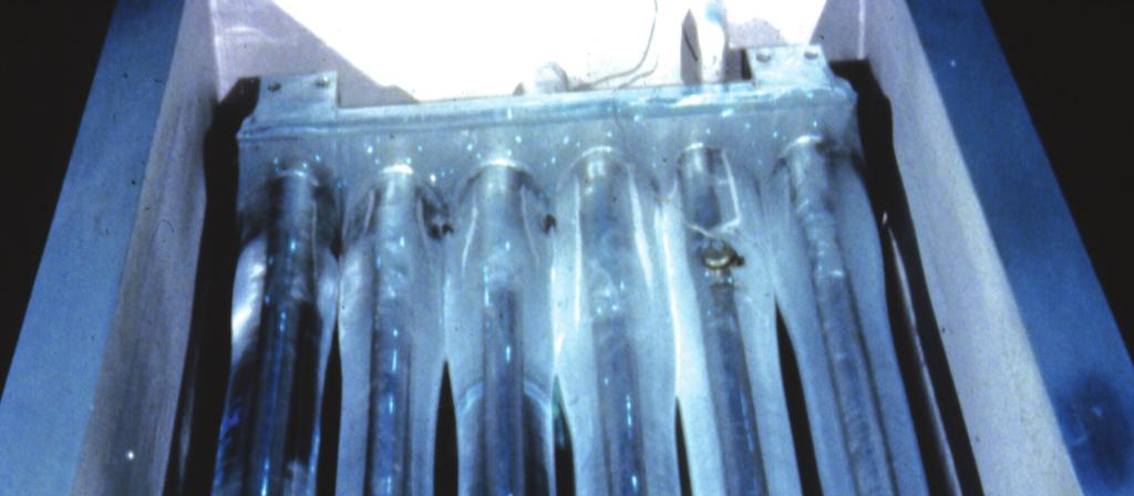
9 - F 9 Construction Details -M - Internal Melt Application 1. Covers Watertight Heavy-gauge Z600 Hot-dip galvanized steel panels Insulated with 50 mm extruded polystyrene insulation 2. Coil Support Beams Prevent contact between coil and primary liner 3. Glycol Connections Threaded connections Flanged connections (optional) 4. Galvanised Steel Coil Hot-dip galvanized after fabrication (HDGAF) Steel tubing, encased in a steel framework Pneumatically tested at 13 bar... because temperature matters
10 - F 10 Rated for 10 bar operating pressure 5. Primary Liner Single piece 48-hour integrity test before shipment 6. Extruded Polystyrene Insulation 110 mm of total insulation 20 mm of insulation between primary and secondary liner Contributes to total insulating value of 3,1m C/W 7. Secondary Liner/Vapor Barrier Prevents moisture from penetrating through the insulation 8. Wall Panel Heavy-gauge glavanised steel with double brake flanges Extruded polystyrene insulation Contributes to total insulating value of 3,1m C/W 9. Sight Tube Visual indicator of the amount of ice remaining in unit 10. Ice Inventory Sensor (Optional) - Not Shown Mechanical Water Level Difference Transmitter provides an electrical 4-20 ma output signal which is proportional to the amount of ice in inventory Baltimore Aircoil
11 - F 11 Engineering Data -M -M & -LM Units REMARK: Do not use for construction. Refer to factory certified dimensions & weights. This brochure includes data current at time of publication, which should be reconfirmed at the time of purchase. In the interest of product improvement, specifications, weights and dimensions are subject to change without notice. Up-to-date engineering data and more can be found at 1. Outlet; 2. Inlet; 3. Sight Tube; 4. Access Hatch. Model -M Latent Capacity (kwh) Approx. Sh. Weight (kg) Approx. Op. Weight (kg) Tank Water Volume (l) Coil Glycol Volume (l) Connection Size ND Unit Width Unit Length Unit Height H1-237M M M M Tank Height H2 Model -LM Latent Capacity (kwh) Approx. Sh. Weight (kg) Approx. Op. Weight (kg) Tank Water Volume (l) Coil Glycol Volume (l) Connection Size ND Unit Width Unit Length Unit Height H1 Tank Height H2 -L184M L370M L462M L592M because temperature matters
 BAC will manufacture custom ICE CHILLER Thermal Storage Coils to meet project specific requirements.")
12 - F 12 General Notes 1. All dimensions are in mm. Weights are in kg. 3. All connections are threaded 2. Unit should be continuously supported on a flat level surface. Custom Coils for Internal Melt Application (-M) BAC will manufacture custom ICE CHILLER Thermal Storage Coils to meet project specific requirements. BAC has done extensive research and testing on the build and melt characteristics of ice storage. This research and testing has resulted in selection capabilities unmatched by any other company in the industry. 4. H1, H2 = installed height. Coils are capped for shipping and storage. Add 75 mm for shipping height. BAC can predict the temperatures required on an hour by hour basis for building ice on custom Installation of Coil Module coils, over a variety of conditions and build times. The physical space available, load profile, discharge temperatures, chiller capacity and operating sequences can be evaluated to find the design that best meets the application. The ICE CHILLER Thermal Storage Coils are constructed of continuous 26,7 mm O.D. all prime surface serpentine steel tubing. The coils are assembled in a structural steel frame designed to support the weight of the coil stack with a full ice build. After fabrication the coils are tested for leaks using 13 bar air pressure under water, then hot-dip galvanized for corrosion protection. The coils are configured to provide countercurrent glycol flow in adjacent circuits for maximum storage capacity. Individual coils can be factory-assembled into modules of two (2) coils for optimization of transport cost and reduction of site assembly time. Glycol manifolds are coated with zinc-rich, cold galvanizing finish at the factory. Necessary support steel and lifting lugs are provided on the modules to allow for lifting into and final positioning within the storage tank. Load Profile A daily load profile is the hour by hour representation of cooling loads for a 24 hour period. Most HVAC applications use a daily load profile to determine the amount of storage required. Some HVAC systems apply a weekly load profile. For conventional air conditioning systems, chillers are selected based on the peak cooling load. For ice storage systems, the chillers are selected based on the kwh of cooling required and a defined operating strategy. Typical HVAC Load Profile Thermal storage systems provide much flexibility for varying operating strategies as long as the total kwh selected are not exceeded. This is why an accurate load profile must be provided when designing an ice storage system. Load profiles take many different shapes based on the application. The figure above illustrates a typical HVAC load profile for an office building with a 1750 kw peak cooling load and a 12 hour Baltimore Aircoil
13 - F 13 cooling requirement. The shape of this curve is representative of most HVAC applications. For preliminary equipment selections, BAC's ICE CHILLER Thermal Storage Unit Selection Program can generate a similar load profile. Information required is the estimated building peak cooling load and duration of the cooling load. The Air Conditioning & Refrigeration Institute (ARI) has published Guideline T, "Specifying the Thermal Performance of Cool Storage Equipment." The purpose of Guideline T is to establish the minimum user specified data and supplier specified performance data. Design data provided by the engineer includes: System Loads, Flow Rates and Temperatures. Operating Strategies Once the load profile is generated, the next step in selecting Thermal Storage equipment is to define an operating strategy or in other words, determine the hours per day during which the glycol chiller is allowed to operate. Which operating strategy to use is dependent upon the load profile (application), the utility rate structure, the energy cost and the equipment first cost. In other words, the economical balance between the system installation and operating cost or the payback period must be calculated. There are 2 different operating strategies, either full or partial storage. Full Storage Systems store all the cooling capacity required during the off peak periods and eliminate the need to operate the chiller(s) during the utility on-peak period. This strategy shifts the largest amount of electrical demand and results in the lowest operating cost. However, the equipment first cost is considerably higher than partial storage systems due to larger chiller and storage requirement and full storage is therefore seldom used. Partial Storage Systems require that the chiller(s) operate also during the on-peak period. The partial storage system allowing the glycol chiller to run for 24 hours per day at its full capacity is most commonly used as it results in the smallest chiller selection. In many cases, the smaller chiller selection is the driving force for an ice storage system because of lower installed electrical kw, smaller refrigerant charge, smaller cooling towers or other heat rejection equipment (lower noise), smaller standby chillers (if required), lower capital and maintenance cost,... Other partial storage operating strategies stop the chiller a few hours per day when electricity cost are high and/or where non-cooling electricity usage are important (so when the chiller operation would increase the electrical demand). It is however important to know that the more hours the chiller is stopped during the day, the larger its size will be. Furthermore, if the chiller is stopped during the cooling period, the size of the storage equipment needs to be increased. If the chiller is stopped during the non-cooling period, the ice build time is reduced and therefore lower glycol temperatures are required and the chiller COP is reduced. Besides determining when the chiller should run or be stopped, an other aspect of operating strategy is if during melt-out, priority is given to the chiller or to the ice to cover the presented cooling load. In a chiller priority system the chiller always operates at full capacity. When the cooling load exceeds the chiller performance, the excess is covered by the melting ice. A constant portion of the load is covered by the chiller while the variation in load is covered by the ice. In an ice priority system, a constant part of the load is covered by the ice, where the variation in load is taken by the chiller. Because the chiller does not continuously operate at its maximum capacity, it will be oversized versus the chiller priority system. Ice priority systems result in oversized ice and chiller selections and are therefore seldom used.... because temperature matters
14 - F 14 Normal practice is that partial storage systems using chiller priority with 24h chiller operation are most commonly used. Modes of Operation The modular ICE CHILLER Thermal Storage Unit can operate in any of five distinct operating modes. These modes of operation provide the flexibility required by building operators to meet their daily HVAC cooling requirements. Ice Build: In this operating mode, ice is built by circulating a 25% solution (by weight) of inhibited ethylene glycol at negative temperatures through the coils contained in the ICE CHILLER Thermal Storage Unit. During this operating mode, the chiller's operating conditions are monitored and the chiller is turned off when the minimum supply glycol temperature off the chiller is reached. Optionally, the ICE LOGIC Ice Quantity Meter is available to control the chiller operation. The figure illustrates typical chiller supply temperatures for 8, 10 and 12 hour build Chiller Supply Temperatures cycles. For a typical 10 hour build time, the supply glycol temperature is never lower than -5,5 C. As the graph illustrates, for build times exceeding 10 hours, the minimum glycol temperature is greater than -5,5 C. For build times less than 10 hours, the minimum glycol temperature will be lower than -5,5 C at the end of the build cycle. This performance is based on a chiller flow rate associated with a 3 C range. When a larger temperature range is the basis of the chiller selection, the chiller supply temperatures will be lower than shown in the figure above. Ice Build with Cooling: When cooling loads exist during the ice build period, some of the cold ethylene glycol used to build ice is diverted to the cooling load to provide the required cooling. The amount of glycol diverted is determined by the building loop set point temperature. BAC recommends that this mode of operation be applied on systems using primary/secondary pumping (See further for system schematic). This reduces the possibility of damaging the cooling coil or heat exchanger by pumping cold glycol, lower than 0 C, to this equipment. Cooling Ice only: In this operating mode the chiller is off. The warm return ethylene glycol solution iscooled to the desired set point temperature by melting ice stored in the modular ICE CHILLER Thermal Storage Unit. Cooling Chiller only: In this operating mode the chiller supplies all the building cooling requirements. Glycol flow is diverted around the thermal storage equipment to allow the cold supply glycol to flow directly to the cooling load. Temperature set points are maintained by the chiller. Cooling Ice with Chiller: In this operating mode, cooling is provided by the combined operation of the chiller and thermal storage equipment. The glycol chiller pre-cools the warm return glycol. The partially cooled glycol solution then passes through the ICE CHILLER Thermal Storage Unit where it is cooled by the ice to the design temperature. Baltimore Aircoil
15 - F 15 System Schematics Two basic flow schematics are applied to select ICE CHILLER Thermal Storage Units. The figure illustrates a single piping loop with the chiller installed upstream of the thermal storage equipment. This design allows the thermal storage system to operate in four of the five possible operating modes. They are Ice Build, Cooling-Ice Only, Cooling-Chiller Only and Cooling Ice with Chiller. For this figure the following control logic is applied: Single loop Chiller Upstream MODE CHILLER P-1 V-1 V-2 Ice Build On On A-B C-B Cooling Ice Only Off On Modulate A-B Cooling Chiller Only On On C-B A-B Cooling Ice with Chiller On On Modulate A-B Valve V-1 modulates in response to temperature sensor, TS-1. Valve V-2 could be positioned to either maintain a constant flow, less than P-1, or modulate in response to the return glycol temperature from the cooling load. When the building loop contains chilled water, a heat exchanger must be installed to separate the glycol loop from the building s chilled water loop. On applications where an existing water chiller is available, it can be installed in the chilled water loop to reduce the load on the thermal storage system. This design should not be used when there is a requirement to build ice and provide cooling. This would require the cold return glycol from the thermal storage equipment be pumped to the cooling load or heat exchanger. Since the glycol temperature is below 0 C, the cooling coil or heat exchanger is subject to freezing. The flow schematic illustrated in the figure details a primary/ secondary pumping loop with the chiller located upstream of the thermal storage equipment. This design allows the system to operate in all five operating modes. For this figure the following control logic is applied: MODE CHILLER P-1 P-2 V-1 V-2 Ice Build On On Off A-B A-C Ice Build with Cooling On On On A-B Modulate Cooling - Chiller Only On On On C-B A-B Cooling Ice Only Off On On Modulate A-B Cooling Ice with Chiller On On On Modulate A-B... because temperature matters
16 - F 16 Primary/Secondary Pumping Loop Chiller Upstream Valve V-1 and Valve V-2 modulate, depending on the operating mode, in response to temperature sensor, TS-1. The benefit provided by the primary/secondary pumping loop is that the system can build ice and provide cooling without fear of freezing a cooling coil or heat exchanger. This system design also allows for different flow rates in each of the pumping loops. When the flow rates in the pumping loops are different, the glycol flow rate in the primary loop should be greater than or equal to the glycol flow rate in the secondary loop. If not, colder supply glycol temperatures from the primary loop are needed to guarantee the design TS-1 set point (because there is always a mix with warm return glycol from the secondary loop. This reduces the chiller COP. At very large flow rate differences, negative glycol temperatures out of the would be needed to obtain TS-1 (which is impossible) As in the single loop schematic, a heat exchanger and a base water chiller can be added to the system schematic. Variations to these schematics are possible but these are the most common for thermal storage systems. One common variation positions the chiller downstream of the thermal storage equipment. This design is used when the glycol temperatures off the ice cannot be maintained for the entire cooling period. By positioning the chiller downstream of the ice, the chiller is used to maintain the required supply temperature. In both of the above figures, the chiller is installed upstream of the ice. This offers two significant advantages compared to system designs that locate the chiller downstream of the ice. First, the chiller operates at higher glycol temperatures to precool the return glycol. This enables the chiller to operate at a higher capacity, which reduces the amount of ice required. Second, since the chiller is operating at higher evaporator temperatures, the efficiency of the chiller is improved. Chiller Performance Most packaged chillers can provide a wide range of glycol discharge temperatures and are suited for thermal storage applications. Chiller types applied to thermal storage applications include reciprocating, rotary screw and centrifugal. The chiller type used depends on capacity, glycol discharge temperature, efficiency, condenser type, and refrigerant. Chiller capacity and glycol discharge temperature must be evaluated when designing a thermal storage system. Different glycol discharge temperatures are required for various operating modes that affect the chiller capacity. The chiller capacity provided at -5,5 C is considerably less than the chiller capacity with a 6 C glycol discharge temperature. Chillers selected for use with the BAC's ICE CHILLER Thermal Storage Units should be able to provide -5,5 C glycol when applied to a 10-hour build cycle. Longer build times result in higher Baltimore Aircoil
17 - F 17 glycol temperatures at the end of the build period while shorter build times require the chiller to supply glycol colder than -5,5 C. The chiller capacity required could limit the use of a specific chiller type on small applications. The nominal capacity range for each chiller type is shown in the table below. Chiller Type Reciprocating Nominal Capacity (kw) Range kw Rotary Screw Centrifugal kw kw+ Centrifugal and rotary screw chillers have the highest efficiencies with COP s from 5,9 to 4,7 at 6 C chiller discharge temperature and 4,0 to 3,2 when providing -5,5 C glycol. Reciprocating chillers are less efficient and have COP s ranging from 4,1 to 3,2 when providing 6 C glycol and 3,2 to 2,7 when making ice at -5,5 C. The heat rejection function of an ice storage system can be handled by any of three types of refrigerant condensers: air cooled, water-cooled or evaporative. An air cooled condenser removes heat from the refrigerant and condenses it by forcing air over an extended surface coil through which the refrigerant vapour is circulated. The latent heat of the refrigerant is removed by sensibly heating the air. The condenser capacity is determined by the ambient dry bulb temperature. A water-cooled condenser with a cooling tower rejects heat from a refrigeration system in two steps. First, the refrigerant is condensed by the water flow in the condenser. Second, heat is rejected to the atmosphere as the condenser water is cooled by a cooling tower. The evaporative condenser combines a water cooled condenser and cooling tower in one piece of equipment. It eliminates the sensible heat transfer step of the condenser water. This allows a condensing temperature substantially closer to the design wet bulb temperature. Variations in condensing temperatures should be considered when evaluating chiller performance. Reduced night-time ambient dry bulb and wet bulb temperatures offer lower condensing temperatures which help offset the reduction in chiller capacity and chiller efficiency. The percent of nominal chiller capacity at various glycol discharge temperatures are shown below. Glycol Discharge Temperature Percent of Nominal Capacity* 6,0 C 97 % 2,0 C 85 % -5,5 C 66 % Note: * Nominal capacity of the chiller is based on cooling water to 6oC.... because temperature matters

18 - F 18 Nominal capacity ratings are based on: z 30 C condenser water or 46 C condensing temperature for cooling operation z 26,5 C condenser water or 40,5 C condensing temperature for ice build operation The refrigerant types for chillers also vary. Centrifugal chillers are available for use with R-134a, R-123 and R-22. Reciprocating and rotary screw chillers are available for use with R 134a, R-22 and R-717 (ammonia). Baltimore Aircoil
19 - F 19 Engineering Specifications -M 1.0 ICE CHILLER Thermal Storage Unit 1.1 General: The ICE CHILLER Thermal Storage Unit shall be Baltimore Aircoil Model -. Overall unit dimensions shall not exceed approximately m by m with an overall height not exceeding m. The operating weight shall not exceed kg 1.2 Thermal Capacity: Each unit shall have a latent kwh storage capacity of kwh to be generated in hours when supplied with l/s of a 25% (by weight) solution of industrially inhibited ethylene/propylene glycol. The minimum glycol temperature 2.0 Construction Details 2.1 Tank: The tank shall be constructed of heavy-gauge Z600 galvanized steel panels and include double brake flanges for structural strength. The tank walls shall be supplied with a minimum of 110 mm of insulation that provides a total insulating value of 3,1 m C/W. The tank design shall utilize two liners. The 1,5 mm E.P.D.M. liners shall be of single piece construction and be suitable for low temperature applications. Liners shall be separated from each other by 20 mm of extruded polystyrene insulation. The tank bottom shall be insulated with 70 mm extruded, polystyrene insulation. 2.2 Covers: The ICE CHILLER Thermal Storage Unit shall be provided with watertight, sectional covers constructed of Z600 hot-dip galvanized steel. The covers shall be insulated with a minimum of 50 mm of extruded polystyrene insulation. 2.3 Heat Transfer Section: Contained within the tank shall be a steel heat exchanger that is constructed of 26,7 mm O.D., all prime surface serpentine steel tubing encased in a steel framework. The coil, which is hot-dip galvanized after fabrication, shall be tested at 1300 kpa air required during the ice build operating mode shall be C. Rated system performance shall be provided in the format recommended by the Air-Conditioning & Refrigeration Institute (ARI) Guideline T. The thermal storage units shall be modular in design. Unit design shall allow units of different sizes to be installed in order to optimize unit selection and minimize space requirements. Tanks sizes can be mixed due to internal piping arrangements that create a balanced flow due to uniform pressure drop through the coil circuits. pressure under water and rated for 1000 kpa operating pressure. The coil circuits are configured to provide maximum storage capacity. Each unit shall be supplied with threaded connections. 2.4 Sight Tube: Each ICE CHILLER Thermal Storage Unit shall be provided with a sight tube mounted on the end of each unit.. The sight tube, which shall be fabricated from clear plastic pipe, displays the tank water level and corresponding ice inventory. Optionally, the exclusive B.A.C. ICE LOGIC Ice Quantity Controller is available for both manual and automatic chiller control. 2.5 Heat Transfer Fluid System: The heat transfer fluid shall be an industrially inhibited, 25% by weight, ethylene glycol solution specifically designed for HVAC applications. The 25% (by weight) solution is designed to provide freeze/burst and corrosion protection as well as efficient heat transfer in water based, closed loop systems. Corrosion inhibitors shall be provided to keep pipes free of corrosion without fouling.... because temperature matters

20 - F 20 Construction Details -C/D - External Melt Application 1. Tank The tank is constructed of heavy-gauge, Z600 hot-dip galvnised steel, reinforced with full-length structural steel angles beneath and on all four sides. All seams are welded to ensure watertight construction. A zinc rich coating is applied to all exposed edges and welds. 2. Insulation Extruded polystyrene insulation is provided between the tank and the exterior panels. The insulation is 80 mm thick on the tank sides and ends, and 50 mm thick on the bottom and inside the covers 3. Exterior Panels Exterior panels sealed at all seams provide a complete vapor barrier and protect the insulation. They are furnished with B.A.C. s exclusive BALTIBOND Corrosion Protection System. 4. Air Pump Centrifugal regenerative blower for field mounting to supply low pressure air for agitation of the water. Pump is complete with a weather protected inlet air filter and is suitable for outdoor applications. Baltimore Aircoil
21 - F Covers Sectional insulated tank covers are proided with B.A.C. s exclusive BALTIBOND Corrosion Protection System. 6. Galvanised Steel Coil Hot-dip galvanised after fabrication (HDGAF) Steel tubing encased in a steel framework Pneumatically tested at 15 bar (31bar) for glycol (ammonia) applications Rated for 10 bar (22 bar) operating pressure 7. ICE-LOGIC Ice Thickness Controller (Not Shown) An electronic, multi-point ice thickness control is mounted on the unit. A control relay is provided to deactivate the refrigeration system when a full build of ice is reached. 8. Air Distribution Low pressure air from the air pump is distributed below the coils through multiple perforated PVC pipes.... because temperature matters
22 - F 22 Engineering Data -C/D -95C C & -185C C REMARK: Do not use for construction. Refer to factory certified dimensions & weights. This brochure includes data current at time of publication, which should be reconfirmed at the time of purchase. In the interest of product improvement, specifications, weights and dimensions are subject to change without notice. Up-to-date engineering data and more can be found at 1. Coil Connections; 2. Make-up ND50; 3. Overflow ND50; 4. Water Out; 5. Water In; 6. Drain ND50; 7. ICE LOGIC. Model Op. Weight (kg) Sh. Weight (kg) Air Pump (kw) Water Volume (l) Pull Down Volume (l) Coil Volume (l) R-717 Charge (kg) Water Conn. In ND Water Conn. Out ND H H1 mm L W -95C , x C , x C , x C , x C , x C , x C , x C , x C , x C , x C , x C , x C , x C , x C , x C , x C C & -790D D REMARK: Do not use for construction. Refer to factory certified dimensions & weights. This brochure includes data current at time of publication, which should be reconfirmed at the time of purchase. In the interest of product improvement, specifications, weights and dimensions are subject to change without notice. Up-to-date engineering data and more can be found at Baltimore Aircoil
23 - F Coil Connections; 2. Make-up ND50; 3. Overflow ND50; 4. Water Out; 5. Water In; 6. Drain ND50; 7. ICE LOGIC. Model Op. Weight (kg) Sh. Weight (kg) Air Pump (kw) Water Volume (l) Pull Down Volume (l) Coil Volume (l) R-717 Charge (kg) Water Conn. In ND Water Conn. Out ND -480C , x C , x C , x C , x C , x C , x D , x D , x D D D H H1 L , x , x , x W TSC-95C - TSC-1050C & TSC-790D - TSC-1440D REMARK: Do not use for construction. Refer to factory certified dimensions & weights. This brochure includes data current at time of publication, which should be reconfirmed at the time of purchase. In the interest of product improvement, specifications, weights and dimensions are subject to change without notice. Up-to-date engineering data and more can be found at because temperature matters
 Coil Volume (l) R-717 Charge (kg) Data Per Coil H H 1 L W TSC-95C TSC-115C TSC-120C TSC-145C TSC-170C TSC-200C TSC-225C 1 1 1 1 1 1 1 1065 1205 1315 1500 1635 1950 2135 297 340 368 453")
24 - F 24 Model TSC No Coils Sh. Weight (kg) Coil Volume (l) R-717 Charge (kg) Data Per Coil H H 1 L W TSC-95C TSC-115C TSC-120C TSC-145C TSC-170C TSC-200C TSC-225C TSC-185C TSC-230C TSC-270C TSC-310C TSC-350C TSC-290C TSC-340C TSC-400C TSC-450C TSC-480C TSC-590C TSC-700C TSC-800C TSC-910C TSC-1050C TSC-790D TSC-940D TSC-1080D TSC-1220D TSC-1440D General Notes 1. All dimensions are in mm. Weights are in kg. 2. Unit should be continuously supported on a flat levelsurface. 3. All connections are threaded 4. H1 = installed height. Coils are capped for shipping and storage. Add 75 mm for shipping height. 5. Refrigerant charge listed is operating charge for pump recirculated bottom feed. For other feed systems, consult your BAC Balticare Representative. Baltimore Aircoil

25 - F 25 Custom Coils for External Melt Application (-C/D) BAC will manufacture custom ICE CHILLER Thermal Storage Coils to meet project specific requirements. B.A.C. has done extensive research and testing on the build and melt characteristics of ice storage. This research and testing has resulted in selection capabilities unmatched by any other company in the industry. BAC can predict the temperatures required on an hour by hour basis for building ice on custom coils, over a variety of conditions and build times. The physical space available, load profile, Coils installed in Concrete Tank discharge temperatures, chiller capacity and operating sequences can be evaluated to find the design that best meets the application. The ICE CHILLER Thermal Storage Coils are constructed of continuous 26,7 mm O.D. all prime surface serpentine steel tubing. The coils are assembled in a structural steel frame designed to support the weight of the coil stack with a full ice build for glycol (ammonia) application. After fabrication the coils are tested for leaks using 15 bar (31bar) air pressure under water, then hotdip galvanized for corrosion protection. The coils are configured to provide countercurrent glycol flow in adjacent circuits for maximum storage capacity. Individual coils can be factory-assembled into modules of two (2) coils for optimization of transport cost and reduction of site assembly time. Glycol manifolds are coated with zinc-rich, cold galvanizing finish at the factory. Necessary support steel and lifting lugs are provided on the modules to allow for lifting into and final positioning within the storage tank. Modes of Operation The ICE CHILLER Thermal Storage Unit operates in two main operating modes or cycles. A possible combination of these cycles of operation provides the flexibility to meet the daily HVAC or cooling requirements. Long periods of simultaneously circulating glycol or ammonia through the coil tubes and circulating water through the ICE CHILLER should however be avoided to optimise system performance. Ice Build: In this operating cycle, ice is built by circulating ammonia or a 30% solution (by weight) of inhibited ethylene/propylene glycol through the coils contained in the ICE CHILLER Thermal Storage Unit. The below table illustrates typical temperatures for 8, 10, 12 and 14 hour build cycles. At the start of the ice build cycle, the temperature will be higher while at the end of the ice build cycle, the temperatures will be lower. Unit Capacity & Average Temperatures for Glycol Applications Model Nominal Capacity (kwh) Flow (l/s) Dp Build Time (h) & Glycol Temperature ( C) 8 h 10 h 12 h 14 h In Out In Out In Out In Out -95C 325 2,4 111,0-8,8-4,4-6,9-3,4-5,8-2,8-5,0-2,4-115C 404 2,4 130,3-9,4-3,8-7,4-2,9-6,2-2,4-5,3-2,1-120C 422 2,8 100,7-9,0-4,2-7,1-3,2-5,9-2,7-5,1-2,3... because temperature matters
26 - F 26 Unit Capacity & Average Temperatures for Glycol Applications Model Nominal Capacity (kwh) Flow (l/s) Dp Build Time (h) & Glycol Temperature ( C) 8 h 10 h 12 h 14 h In Out In Out In Out In Out -145C 510 2,8 117,9-9,5-3,7-7,5-2,8-6,3-2,4-5,4-2,1-170C 597 2,8 134,4-10,0-3,2-7,9-2,4-6,6-2,1-5,7-1,8-200C 703 5,4 71,0-8,7-4,4-6,9-3,4-5,8-2,9-4,9-2,5-225C 791 5,4 78,6-9,0-4,2-7,1-3,2-5,9-2,7-5,1-2,3-185C 650 4,7 111,0-8,8-4,4-6,9-3,4-5,8-2,8-5,0-2,4-230C 808 4,7 130,3-9,4-3,8-7,4-2,9-6,2-2,4-5,3-2,1-270C 949 8,5 63,4-8,4-4,8-9,6-3,7-5,6-3,1-4,8-2,7-310C ,5 71,0-8,7-4,5-6,8-3,5-5,7-2,9-4,9-2,5-350C ,5 78,6-8,9-4,3-7,1-3,3-5,9-2,8-5,1-2,4-290C ,7 117,9-9,5-3,7-7,5-2,8-6,3-2,4-5,4-2,1-340C ,7 134,4-10,0-3,2-7,9-2,4-6,6-2,1-5,7-1,8-400C ,7 71,0-8,7-4,4-6,9-3,4-5,8-2,9-4,9-2,5-450C ,7 78,6-9,0-4,2-7,1-3,2-5,9-2,7-5,1-2,3-480C ,7 93,8-9,2-4,1-7,2-3,1-6,1-2,6-5,2-2,2-590C ,7 108,2-9,7-3,4-7,7-2,6-6,4-2,2-5,6-1,9-700C ,4 135,8-10,1-3,1-8,0-2,3-6,7-1,9-5,8-1,7-800C ,5 72,4-8,7-4,4-6,9-3,4-5,8-2,9-4,9-2,5-910C ,5 79,3-9,0-4,2-7,1-3,2-5,9-2,7-5,1-2,3-1050C ,0 137,3-10,1-3,1-8,0-2,4-6,7-2,0-5,7-1,7-790D ,4 73,1-8,2-5,0-6,5-3,8-5,4-3,2-4,7-2,8-940D ,4 82,7-8,6-4,6-6,7-3,6-5,7-3,0-4,8-2,6-1080D ,4 91,7-8,8-4,4-7,0-3,3-5,8-2,8-5,0-2,4-1220D ,4 100,7-9,1-4,1-7,2-3,1-6,1-2,6-5,2-2,3-1440D ,4 114,5-9,6-3,6-7,6-2,7-6,3-2,3-5,4-2,0 Unit Capacity for Ammonia Applications Model Pump Recirculation Refrigerant Feed Nominal Capacity kwh Gravity Flooded Refrigerant Feed Nominal Capacity kwh Model Pump Recirculation Refrigerant Feed Nominal Capacity kwh Gravity Flooded Refrigerant Feed Nominal Capacity kwh -95C C C C C C C C C C C C C C C C C D C D C D C D 4040 N.A. Baltimore Aircoil
27 - F 27 Unit Capacity for Ammonia Applications Model Pump Recirculation Refrigerant Feed Nominal Capacity kwh Gravity Flooded Refrigerant Feed Nominal Capacity kwh Model Pump Recirculation Refrigerant Feed Nominal Capacity kwh Gravity Flooded Refrigerant Feed Nominal Capacity kwh -290C D 4639 N.A. -340C Storage Factor Design Evaporator Temperature Pump Recirculation Refrigerant Feed C Ice Melt: In this operation cycle the warm return water is cooled by direct contact between the water and the ice, melting ice stored in the modular ICE CHILLER Thermal Storage Unit. System Schematics Temperatures for Ammonia Applications Design Evaporator Temperature Gravity Flooded Refrigerant Feed C Build Time Build Time Storage 8 h 10 h 12 h 14 Factor 8 h 10 h 12 h 14 h 1,00-6,1-4,9-4,1-3,6 1,00-5,8-4,8-4,2-3,7 1,05-5,7-4,6-3,9-3;4 1,05-5,5-4,6-3,9-3,5 1,10-5,3-4,3-3,7-3,2 1,10-5,2-4,3-3,7-3,3 1,15-5,0-4,1-3,5-3,0 1,15-5,0-4,1-3,6-3,2 1,20-4,7-3,9-3,3-2,8 1,20-4,7-3,9-3,4-3,0 1,25-4,5-3,7-3,1-2,7 1,25-4,5-3,8-3,3-2,9 1,30-4,3-3,5-3,0-2,6 1,30-4,3-3,6-3,1-2,8 The basic ice storage system includes an ICE CHILLER Thermal Storage Unit, a refrigeration system and ice water pump as shown below. The ICE CHILLER Unit consists of a multiple tube serpentine coil submerged in an insulated tank of water. Both the coil and tank are constructed from hot-dip galvanized steel for corrosion protection. When no cooling load exists, the refrigeration system operates to build ice on the outside surface of the coil. This refrigeration effect is provided by feeding refrigerant directly into the coil. To increase the heat transfer during the ice build cycle the water is agitated by air bubbles from a low pressure distribution system beneath the coil. When the ice has reached design thickness, BAC s exclusive ICE-LOGIC Ice Thickness Controller sends a signal to turn off the refrigeration system. When chilled water is required for cooling, the chilled water pump is started, and the melt out cycle begins. Warm water returning from the load circulates through the ICE CHILLER tank and is cooled by direct contact with the melting ice. During this cycle, the tank water is also agitated to enhance heat transfer and typically provides a constant supply water temperature of 1 C or less. For a closed chilled water loop see figure below. With this system, warm return water from the load is pumped through a heat exchanger and cooled by the ice water circuit from the ICE CHILLER Unit. For more detailed information on the design and operation of BAC ICE CHILLER Thermal Storage Units, contact your local BAC Balticare Representative.... because temperature matters

28 - F 28 Basic Scheme External Melt Scheme with Intermediate Heat Exchanger Baltimore Aircoil
Product Introduction...F2. Benefits...F4. Proven Technology...F8. Construction Details...F12. Engineering Data...F14. Custom Coils...
 ICE CHILLER F1 Product Detail Product Introduction....................................F2 Benefits................................................F4 Proven Technology......................................F8
THERMAL ICE STORAGE: Application & Design Guide
 THERMAL ICE STORAGE: Application & Design Guide Table of Contents: 1. Introduction A. History of Thermal Energy Storage B. Operating and Cost Benefits 2. Applications A Fundamental System B. HVAC Cooling
A Technical Introduction to Cool Thermal Energy Storage Commercial Applications
 A Technical Introduction to Cool Thermal Energy Storage Commercial Applications Cool Thermal Energy Storage is a new application of an old idea that can cut air conditioning energy costs in half while
Building air conditioning systems using Ice-Cel thermal storage can be designed which cost little or no more than conventional chiller-only systems.
 WHY THERMAL STORAGE? Thermal storage is a technology that has come of age. It meets today's need for flexible energy management. Whether you're the owner of a large building, a school executive, a hospital
Evaporative Condensers
 J2 BAC offers evaporative condensers in six different styles to suit every industry application. CXV Models - CXV models deliver efficient performance in an easy-to-maintain package. BAC s combined flow
Closed Circuit Cooling Towers
 VFL - C 35 Closed Circuit Cooling Towers Product Detail VFL Closed Circuit Cooling Tower... C36 Benefits... C38 Construction Details... C40 Custom Features and Options... C41 Accessories... C43 Engineering
Evaporative Condensers
 VXC - E 13 Evaporative Condensers Product Detail VXC Evaporative Condensers... E14 Benefits... E16 Construction Details... E18 Custom Features and Options... E20 Accessories... E22 Engineering Data...
HVAC Water chiller selection and optimisation of operation
 HVAC Water chiller selection and optimisation of operation Introduction Water-chiller is a broad term describing an overall package that includes an electrical control panel, refrigeration plant, water
INTEGRATED SOLUTIONS BY ICE-CEL. Tube-In-Tank Ice Thermal Storage Systems. Products that perform...by people who care.
 INTEGRATED SOLUTIONS BY ICE-CEL Tube-In-Tank Ice Thermal Storage Systems INTEGRATED SOLUTIONS BY Products that perform...by people who care. WHY THERMAL STORAGE? Thermal storage is a technology that has
Method to test HVAC equipment at part load conditions
 IPLV Method to test HVAC equipment at part load conditions For water cooled chillers: 100% load ( % hrs) + 75% ( Hrs ) + 50% ( Hrs ) + 25% ( Hrs ) = IPLV value Manufacturer can favor this number by tweaking
BASE LEVEL AUDIT REQUIREMENTS REFRIGERATION SYSTEMS 1. SITE DATA COLLECTION. Business Name. Site physical address (Street, Suburb, City)
") BASE LEVEL AUDIT REQUIREMENTS REFRIGERATION SYSTEMS 1. SITE DATA COLLECTION Business Name Site physical address (Street, Suburb, City) Nature of site / business operation Electricity Supplier Power factor
BASE LEVEL AUDIT REQUIREMENTS REFRIGERATION SYSTEMS 1. SITE DATA COLLECTION Business Name Site physical address (Street, Suburb, City) Nature of site / business operation Electricity Supplier Power factor
VTL Open Cooling Towers... B98. Benefits... B100. Construction Details... B102. Custom Features and Options... B103. Accessories...
 . - B 97 Product Detail... B98 Benefits... B100 Construction Details... B102 Custom Features and Options... B103 Accessories... B Engineering Data... B107 Structural Support... B111 Engineering Specifications...
1.1 This section applies to air handling units for HVAC Systems.
 AIR HANDLING UNITS GENERAL INFORMATION 1.1 This section applies to air handling units for HVAC Systems. DESIGN REQUIREMENTS 2.1 Design Criteria a. The decision to use modular central station air handling
SYSTEM DESIGN REQUIREMENTS
 P a g e 1 SYSTEM DESIGN REQUIREMENTS WFC-S SERIES WATER-FIRED SINGLE-EFFECT ABSORPTION CHILLERS / CHILLER-HEATERS Yazaki WFC-S Series water-fired chillers and chiller-heaters are available with nominal
2013 Guideline for Specifying the Thermal Performance of Cool Storage Equipment. AHRI Guideline T (I-P)
") 2013 Guideline for Specifying the Thermal Performance of Cool Storage Equipment AHRI Guideline T (I-P) IMPORTANT SAFETY DISCLAIMER AHRI does not set safety standards and does not certify or guarantee the
2013 Guideline for Specifying the Thermal Performance of Cool Storage Equipment AHRI Guideline T (I-P) IMPORTANT SAFETY DISCLAIMER AHRI does not set safety standards and does not certify or guarantee the
Commercial Buildings Chilled water systems efficiency By Jens Nørgaard, Senior Application Manager, Grundfos, Denmark
 Commercial Buildings Chilled water systems efficiency By Jens Nørgaard, Senior Application Manager, Grundfos, Denmark Introduction: Energy use is the single largest operating expense in commercial office
Life-Cycle Energy Costs and Greenhouse Gas Emissions for Gas Turbine Power
 energy center Paper Report Summary 210-1 174-2 Fixed and Floating Head Pressure Comparison for Madison Ice Arena Life-Cycle Energy Costs and Greenhouse Gas Emissions for Gas Turbine Power July 1998 April,
Energy Efficiency Through Waste Heat Recovery. Heat Recovery Centrifugal Chillers and Templifier Water Heaters
 Energy Efficiency Through Waste Heat Recovery Heat Recovery Centrifugal Chillers and Templifier Water Heaters Innovative Solutions for Saving Energy McQuay offers two innovative methods of saving energy
HVAC - Central System Thermal Storage
 HVAC - Central System Thermal Storage General Thermal storage is a cost saving technique, and in some cases, energy saving technology. Commercial cooling can account for as much as 40% of peak demand on
Chiller Plant Design. Julian R. de Bullet President debullet Consulting
 Chiller Plant Design Julian R. de Bullet President debullet Consulting 703-483-0179 julian@debullet.com This ASHRAE Distinguished Lecturer is brought to you by the Society Chapter Technology Transfer ASHRAE
Air Conditioning Clinic
 Air Conditioning Clinic Ice Storage Systems One of the Systems Series August 2012 TRG-TRC019-EN Ice Storage Systems One of the Systems Series A publication of Trane Preface Ice Storage Systems A Trane
INTRODUCTION HVAC BASICS AND HVAC SYSTEM EFFICIENCY IMPROVEMENT SECTION O 4/19/2012
 HVAC BASICS AND HVAC SYSTEM EFFICIENCY IMPROVEMENT SECTION O INTRODUCTION HVAC systems or Heating, Ventilating and Air-Conditioning systems control the environment for people and equipment in our facilities.
Closed Circuit Cooling Towers
 Closed Circuit Cooling Towers Overview Closed circuit cooling towers provide evaporative cooling for many types of systems, and the specific application will largely determine which BAC Closed Circuit
JCseries EVAPORATIVE CONDENSER. engineering data
 JCseries EVAPORATIVE CONDENSER engineering data Recold JC Series Evaporative Condenser Contents 2 Construction... 3 Schematic... 4 Engineering Data... 5 Selection Procedure... 6-9 Multi-Circuited Selection
Closing the Loop What s best for your system?
 What s best for your system? Heat Rejection System Design Choices Consulting Engineers have two choices when designing a heat rejection system whether the cooling loop is open to the atmosphere or a closed
BRINE CIRCULATED ICE THERMAL STORAGE SYSTEM DESIGN - CASE ILLUSTRATION - Partial Ice Storage for Air Conditioning Application
 1 BRINE CIRCULATED ICE THERMAL STORAGE SYSTEM DESIGN - CASE ILLUSTRATION - Partial Ice Storage for Air Conditioning Application By: T. S. Wan Date: Oct. 7, 1995 Copy Right 1995 by T. S. Wan All rights
Energy Savings Potential of Passive Chilled Beam System as a Retrofit Option for Commercial Buildings in Different Climates
 Purdue University Purdue e-pubs International High Performance Buildings Conference School of Mechanical Engineering 2014 Energy Savings Potential of Passive Chilled Beam System as a Retrofit Option for
AIR-CONDITIONING SYSTEMS AND APPLICATIONS. Abdullah Nuhait Ph D. King Saud University
 AIR-CONDITIONING SYSTEMS AND APPLICATIONS Abdullah Nuhait Ph D. King Saud University AIR-CONDITIONING SYSTEMS Earliest air conditioning system used only for heating (winter) Provided heated air for comfort
Series. Chillers and. Features: Application Flexibility Minimizes Installation Time and Reduces Cost
 LL Chillers and Outdoor Mechanical Rooms Air-Cooled Features: Air-cooled condenser chillers with capacities from 35-345 tons Evaporative-cooled condenser chillers with capacities from 35-540 tons Variable
DIVISION 15 MECHANICAL
 DIVISION 15 MECHANICAL A. GENERAL DESIGN CONDITIONS 1. Design occupied spaces to maintain 72 F and a space dew point temperature not to exceed 55 F. 2. Design classroom and office space buildings with
terminal units only provide sensible cooling, a separate dehumidification system is usually needed.
 providing insights for today s hvac system designer Engineers Newsletter volume 44 3 Dual-Temperature Chiller Plants This Engineers Newsletter describes several dual-temperature configurations that can
TrilliumSeries Condenser 1 TRILLIUMSERIES CONDENSER 10 ECOFLEX CONTROLS 11 SELECTION AND PAYBACK ANALYSIS SOFTWARE 3 BENEFITS 8 MODES OF OPERATION
 TrilliumSeries Condenser T A B L E O F C O N T E N T S 1 TRILLIUMSERIES CONDENSER 3 BENEFITS 8 MODES OF OPERATION 9 ENGINEERING DATA 10 ECOFLEX CONTROLS 11 SELECTION AND PAYBACK ANALYSIS SOFTWARE 12 CO
Fans and Pumps I. Dr. Sam C. M. Hui Department of Mechanical Engineering The University of Hong Kong
 MEBS6008 Environmental Services II http://www.mech.hku.hk/bse/mebs6008/ Fans and Pumps I Dr. Sam C. M. Hui Department of Mechanical Engineering The University of Hong Kong E-mail: cmhui@hku.hk Sep 2012
CTI Sponsored Educational Program
 Presented By: Kent Martens SPX Cooling Technologies, Inc. Slide No.: 1 CTI Mission Statement To advocate and promote the use of environmentally responsible Evaporative Heat Transfer Systems (EHTS) for
TrilliumSeries. Condenser
 TrilliumSeries Condenser TrilliumSeries Condenser The TrilliumSeries Condenser uses a patented Dry-Coil Adiabatic Design that saves energy, reduces refrigerant change, and lowers operating costs. The TrilliumSeries
Reinventing Energy Efficiency WARMNESS.
 Residential WATER2WATER WT SERIES Reinventing Energy Efficiency WARMNESS www.fhp-mfg.com Environmental stewardship is a core philosophy for FHP Manufacturing from design to production to the reduction
Adsorption Chillers Energysmart Green Cooling
 Adsorption Chillers Energysmart Green Cooling New Partners in innovation Leaders in Dehumidification... Worldwide Power Partner Inc USA www.bryair.com Recover Low Grade Process Waste Heat For Energy Smart
PINNACLE SERIES DEDICATED OUTDOOR AIR SYSTEM ENERGY EFFICIENT DEHUMIDIFICATION
 ENERGY EFFICIENT DEHUMIDIFICATION PINNACLE SERIES DEDICATED OUTDOOR AIR SYSTEM Provides a very high degree of latent cooling using only a minimal amount of conventional cooling input Substantial energy
Gas-Fired Double-Effect Chiller-Heater
 Gas-Fired Double-Effect Chiller-Heater CH-K Series: 30, 40, 50, 60, 80, 100 RT Cooling with Standard Heating Capacities W E A R E F R I E N D L Y T O T H E E A R T H Gas-Fired Double-Effect Chiller-Heater
Product Introduction...E35. Benefits...E37. Construction Details...E39. Custom Features & Options...E41. Accessories...E44. Engineering Data...
 Series V Closed Circuit Cooling Towers Product Detail Closed Circuit Cooling Towers Product Introduction...................................E35 Benefits...............................................E37
MH fluid cooler HYBRID DESIGN. HIGHER PERFORMANCE.
 MH fluid cooler HYBRID DESIGN. HIGHER PERFORMANCE. Hybrid Design. Utilizing a combination of evaporative fill media and prime surface coil(s), the MH Fluid Cooler offers significantly improved performance
Alfa Laval Wet Surface Air Coolers (WSAC ) FAQs
 FAQs") Alfa Laval Wet Surface Air Coolers (WSAC ) FAQs Q: How is the WSAC a closed-loop cooling system? A: The WSAC is a closed-loop cooling system because the process loop being cooled is inside the tube bundles
Alfa Laval Wet Surface Air Coolers (WSAC ) FAQs Q: How is the WSAC a closed-loop cooling system? A: The WSAC is a closed-loop cooling system because the process loop being cooled is inside the tube bundles
How to Cut Chiller Energy Costs by 30%
 How to Cut Chiller Energy Costs by 30% Pre-packaged retrofit cuts centrifugal compressor chiller energy costs by 30% while reducing required maintenance and extending operating life at Duke Realty Corporation
MH Fluid Cooler HYBRID DESIGN. HIGHER PERFORMANCE.
 MH Fluid Cooler HYBRID DESIGN. HIGHER PERFORMANCE. Hybrid Design. Utilizing a combination of evaporative fill media and prime surface coil(s), the MH Fluid Cooler offers significantly improved performance
Air Conditioning Clinic. Absorption Water Chillers One of the Equipment Series TRG-TRC011-EN
 Air Conditioning Clinic Absorption Water Chillers One of the Equipment Series TRG-TRC011-EN Absorption Water Chillers One of the Equipment Series A publication of The Trane Company Worldwide Applied Systems
RSES Technical Institute Training Manual 3 72 hours, 72 NATE CEHs, 7.2 CEUs
 Lesson 1 - Basic Heat Pump Theory (Part 1) Describe the basic operation of a heat pump. Explain the function of various heat pump controls. Interpret the wiring diagrams and performance data provided by
Guide Spec Summary. Option List. Date: 05/21/2001. EarthWise VAV Terminal Units Full Spec. Prepared by: Phone Number: Prepared for:
 Date: 05/21/2001 Time: 02:57:44 PM Job Name: EarthWise VAV Terminal Units Full Spec Location: AnyTown, Earth Prepared by: Phone Number: Prepared for: Guide Spec Summary Option List SINGLE & DUAL DUCT UNIT
CONTENTS. B. System Design and Performance Requirements
 15625 Water Chillers This document provides design standards only, and is not intended for use, in whole or in part, as a specification. Do not copy this information verbatim in specifications or in notes
OACS Outdoor Air-Cooled Central Chillers
 OACS Outdoor Air-Cooled Central Chillers Proudly Made In The USA since 1977 A Complete Central Chiller System Complete Central Chiller system with Integrated Reservoir and Pump all mounted on a single
9. ENERGY PERFORMANCE ASSESSMENT OF HVAC SYSTEMS
 9. ENERGY PERFORMANCE ASSESSMENT OF HVAC SYSTEMS 9.1 Introduction Air conditioning and refrigeration consume significant amount of energy in buildings and in process industries. The energy consumed in
Lenntech. Tel Fax
 Lenntech info@lenntech.com Tel. +31-152-610-900 www.lenntech.com Fax. +31-152-616-289 MC Fluid Cooler Unmatched reliability Heavy-duty construction, high performance design and our five-year mechanical
DEMONSTRATION OF ADVANCED INTEGRATED HVAC&R SYSTEMS IN A LOBLAWS SUPERMARKET IN CANADA
 DEMONSTRATION OF ADVANCED INTEGRATED HVAC&R SYSTEMS IN A LOBLAWS SUPERMARKET IN CANADA Daniel Giguère, Technology Expert Georgi Pajani, Engineer Sophie Hosatte, Section Head, Buildings CETC-Varennes, Natural
DISTRIBUTION SYSTEMS. Water Piping and Pumps
 DISTRIBUTION SYSTEMS Water Piping and Pumps Technical Development Programs (TDP) are modules of technical training on HVAC theory, system design, equipment selection and application topics. They are targeted
RAPB. Multi-Purpose Facility. Characteristics of Hockey Rink. Project profile Refrigeration technological innovation
 Project profile Refrigeration technological innovation RAPB REFRIGERATION ACTION PROGRAM FOR BUILDINGS Dow Centennial Centre (Alberta) NEW CONSTRUCTION Summary Potential for total heat recovery from refrigeration
July 2012 was a significant date for the HVAC and Refrigeration industry as it saw the introduction of the Carbon Tax and the HFC Levy.
 Parilla Thermal Storage Project In 2013 Glaciem Cooling Technologies undertook the commercialisation of its Thermcold Thermal Storage system, the system which has been operating now for over two years
Guidelines for energy efficient heating, ventilation and air conditioning (HVAC) systems
 systems") Guidelines for energy efficient heating, ventilation and air conditioning (HVAC) systems If you're a designer or a BCA, this guidance on the energy efficiency of HVAC systems in commercial buildings may
Guidelines for energy efficient heating, ventilation and air conditioning (HVAC) systems If you're a designer or a BCA, this guidance on the energy efficiency of HVAC systems in commercial buildings may
Be sustainable while protecting your business
 Be sustainable while protecting your business Aquaflair 50Hz Air-cooled chillers and free-cooling chillers with double screw compressors and HFO R1234ze refrigerant (400V/3ph/50Hz) 300-1000 kw Aquaflair
The Creative and Performing Arts High School (CAPA) Pittsburgh, PA 11/11/2002 Andrew Tech Mechanical Option Prof. S. A. Mumma
 Pittsburgh, PA 11/11/2002 Andrew Tech Mechanical Option Prof. S. A. Mumma") Objectives and Requirements For the Creative and Performing Arts High School (CAPA), the main objective of the mechanical design is to provide an energy efficient system that is easily maintainable and
Objectives and Requirements For the Creative and Performing Arts High School (CAPA), the main objective of the mechanical design is to provide an energy efficient system that is easily maintainable and
Evaporative Cooling Products
 Evaporative Cooling Products 1 1 Chapter 1: Evaporative Cooling Products Cooling towers and evaporative condensers are efficient and cost effective means of removing heat from air conditioning, refrigeration
PAPER NO: ANDREW RUSHWORTH
 PAPER NO: 18-15 CATEGORY: HVAC Applications COOLING TECHNOLOGY INSTITUTE Closing The Loop Which Method is Best for Your System? FRANK MORRISON ANDREW RUSHWORTH BALTIMORE AIRCOIL COMPANY The studies and
Overview. Heating and Cooling System Strategy
 HEATING AND COOLING SYSTEM UPGRADES Overview Heating and cooling systems are the largest single consumers of energy in buildings. These systems condition the air within a building so that occupants are
AC SYSTEM CONFIGURATION- CENTRAL CHILLER PLANT
 AC SYSTEM CONFIGURATION- CENTRAL CHILLER PLANT Central Chiller Plant (with Cooling Tower and Chilled Water distribution) The other AC configuration is called a Chilled Water or Larger Cooler system. It
Cold Weather Operation Of Cooling Towers
 This article was published in ASHRAE Journal, March 2014. Copyright 2014 ASHRAE. Posted at www.ashrae.org. This article may not be copied and/or distributed electronically or in paper form without permission
APPA Institute for Facilities Management. Energy & Utilities Cooling Production (316) Purpose of Today s Presentation. Agenda
 Purpose of Today s Presentation. Agenda") APPA Institute for Facilities Management Energy & Utilities Cooling Production (316) Mark St. Onge, EFP 1 Purpose of Today s Presentation To provide a broad understanding of central cooling production
APPA Institute for Facilities Management Energy & Utilities Cooling Production (316) Mark St. Onge, EFP 1 Purpose of Today s Presentation To provide a broad understanding of central cooling production
c o n d e n s e r Glossary of Terms
 c o n d e n s e r Glossary of Terms ARI Standard Conditions 85 F. water inlet; 95 F. water out; 105 F. condensing; 0.0005 fouling factor Flow Rate or Velocity The speed at which the condensing water travels
Nirvana. Cycling Refrigerated Dryers
 Nirvana Cycling Refrigerated Dryers Nirvana Cycling Refrigerated Dryers Reliability Is Our Design Ingersoll Rand's Nirvana Cycling Refrigerated Dryer provides reliability like no other dryer in its class:
Topic 2. ME 414/514 HVAC Systems Overview Topic 2. Equipment. Outline
 ME 414/514 HVAC Systems Overview Equipment Outline 2-1 The Complete System 2-2 The Air-Conditioning and Distribution System 2-3 Mechanical Equipment Air-handling Equipment Heating Equipment Boilers Furnaces
Dehumidifying with Dedicated Outdoor Air
 Dehumidifying with Dedicated Outdoor Air System Configurations Figure 71. Configurations for dedicated outdoor-air systems A dedicated outdoor-air handler separately filters, cools, dehumidifies, heats,
MTW Series Modular Oil Free Centrifugal Chillers
 TW Series odular Oil Free Centrifugal Chillers Cooling Capacity:300-2890kW odular Chiller agnetic Levitating Centrifugal Compressor Stainless Steel PHE Refrigerant R134A ax. COP: 12w/w TW Series odular
Vicot Air Conditioning Co., Ltd. CONTENT
 CONTENT I. Introduction 2 II. Absorption Principle 3 III. GAX Absorption Cycle 3 IV. Major Component Description and Function 4 V. Features 4 VI. Performance curve 5 VII. Nomenclature 5 VIII. Technical
Brown University Revised August 3, 2012 Facilities Design & Construction Standards SECTION AIR HANDLING UNITS
 SECTION 23 70 00 AIR HANDLING UNITS PART 1. GENERAL 1.1 Section includes air-handling units to 15,000 cfm and accessories. 1.2 Related Sections 1 : A. Division 01 - Brown University Standard for Narragansett
HYBRID ADIABATIC Cooling System
 Blending Conveying Drying Process Cooling Heat Transfer Size Reduction HYBRID ADIABATIC Cooling System Water & Energy Savings Low Maintenance Improved Health & Safety Hybrid design combines dry cooler
Un-Used Series CXV Evaporative Condenser
 Un-Used Series CXV Evaporative Condenser Mfg: Baltimore Aircoil Company Stock No. NBAC01. Model: CXV-253 Serial No. Un-Used Baltimore Aircoil Company CXV Evaporative Condenser. Model CXV-253. BAC Series
Parilla Thermal Storage Project Case Study. May Page 1 of 11
 Parilla Thermal Storage Project Case Study May 2014 Page 1 of 11 BACKGROUND Parilla Premium Potatoes is a large refrigerated storage facility (Figure 1) located in South Australia; the facility consists
PACKAGED REFRIGERATION EQUIPMENT
 PACKAGED REFRIGERATION EQUIPMENT BUYER S GUIDE WHAT TO LOOK FOR WHEN SELECTING LOW-CHARGE PACKAGED REFRIGERATION EQUIPMENT for your facility 2 Packaged Refrigeration Equipment Buyer s Guide What to look
- Essay Control Functions and Benefits
 - Essay Control Functions and Benefits E 005 07/01 A hydronic heating control system performs many complex and important functions. Each of these functions provide benefits that make the system comfortable,
A Cover ENERGY EFFICIENT
 A Cover Refrigeration ENERGY EFFICIENT EQUIPMENT toolkit 1 CONTENTS and partners 2 Introduction 3 equipment & processes 3 Optimise operating conditions 4 upgrade equipment 4 Cool the product before refrigeration
Sustainable Techniques in Refrigerated Space
 Sustainable Techniques in Refrigerated Space Sustainability and high performance of refrigerated space used for the preservation of perishable product capitalizes on conservation techniques which reduce
Ammonia. Background on ammonia as a refrigerant
 Ammonia Danfoss Industrial refrigeration has written a technical paper on things to consider when changing from HFC/HCFC s to ammonia. It outlines some of the main differences between the different plant
H EDRICK ASSOCIATES OF GRAND RAPIDS West Michigan s Factory Representative
 A U.S. Environmental Protection Agency survey released in 2007 concluded that IT data centers consumed 61 billion kw of electricity at a total cost of $4.5 billion in 2006. As energy costs continue to
Daikin Blueprint: Delivering Hot Water with a Chiller
 Daikin Blueprint: Delivering Hot Water with a Chiller Analyzing the design of heat recovery on air-cooled chillers and the effect it has on building energy consumption By Paul Crisman Daikin Chiller Applications
DENVER PUBLIC SCHOOLS DESIGN AND CONSTRUCTION STANDARDS This Standard is for guidance only. SECTION REFRIGERATION
 PART 0 A/E INSTRUCTIONS 0.01 DESIGN REQUIREMENTS A. General: 1. Design and specify refrigeration systems and equipment in accordance with "Energy Conservation Standards" stipulated in Section 15010, Basic
APPLICATIONS FOR HVAC SYSTEMS
 H E A T E X C H A N G E R S BULLETIN NO. TIS-112A PLATE & FRAME HEAT EXCHANGERS APPLICATIONS FOR HVAC SYSTEMS THE heat transfer people H E A T E X C H A N G E R S 2 Highly Efficient Low Cost Expandable
Heat Recovery Dehumidification (HRD) system. Designed for municipal swimming pools
 system. Designed for municipal swimming pools") Heat Recovery Dehumidification (HRD) system Designed for municipal swimming pools A dehumidification and ventilation system with dynamic heat pump heat recovery to swimming pool water and air ENVIRONMENTAL
Heat Recovery Dehumidification (HRD) system Designed for municipal swimming pools A dehumidification and ventilation system with dynamic heat pump heat recovery to swimming pool water and air ENVIRONMENTAL
Water Piping and Pumps
 Technical Development Program DISTRIBUTION SYSTEMS Water Piping and Pumps PRESENTED BY: Michael Ho carriertdp@gmail.com 424-262-2144 Menu Section 1 Section 2 Section 3 Section 4 Section 5 Section 6 Section
A. Air Handling Units shall be designed to the specific requirements of the application: Recirculation or 100% Makeup.
 SECTION 23 70 00- CENTRAL HVAC EQUIPMENT PART 1: GENERAL 1.1 PURPOSE: A. This standard is intended to provide useful information to the Professional Service Provider (PSP) to establish a basis of design.
Modular Active. Chilled. Beams
 Modular Active Chilled Beams How Twa MAC Beams Work Primary air (100% outside air) is dehumidified to between 50-57 F dew point and is used to: control the latent requirements of the space, provide fresh
By Thomas H. Durkin, P.E., Member ASHRAE, and James B. (Burt) Rishel, P.E., Fellow/Life Member ASHRAE
 Rishel, P.E., Fellow/Life Member ASHRAE") By Thomas H. Durkin, P.E., Member ASHRAE, and James B. (Burt) Rishel, P.E., Fellow/Life Member ASHRAE T he advent of the small scroll or screw chiller, capable of producing condenser water as high as 140
By Thomas H. Durkin, P.E., Member ASHRAE, and James B. (Burt) Rishel, P.E., Fellow/Life Member ASHRAE T he advent of the small scroll or screw chiller, capable of producing condenser water as high as 140
Energy efficient vacuum freezing ice slurry generation using a R718 compressor
 Institute of Air-handling and Refrigeration (ILK Dresden) Energy efficient vacuum freezing ice slurry generation using a R718 compressor ATMOsphere Europe 2013 ILK Dresden R&D company Founded in 1964 Re-established
Energy Management and Controls
 As with the Chapter Review Tests and the Final Exam, the tests your understanding of the materials underlying the learning objectives. After you ve reviewed your answers to the Chapter Review Tests, try
Air-Cooled Variable Speed Drive Screw Chillers. Super Efficient Super Quiet. Cooling Capacity Range kw R134a
 Air-Cooled Variable Speed Drive Screw Chillers Super Efficient Super Quiet Cooling Capacity Range 540-1405 kw R134a World s first low sound Air-Cooled variable speed drive screw chiller The recognition
SECTION REFRIGERATION. 1. Reciprocating Compressors (Hermetic). 2. Reciprocating Compressors (Open Drive). 3. Water Cooled Condensing Units.
. 2. Reciprocating Compressors (Open Drive). 3. Water Cooled Condensing Units.") SECTION 15650 REFRIGERATION PART 1 - GENERAL 1.01 SUMMARY A. Section Includes: 1. Reciprocating Compressors (Hermetic). 2. Reciprocating Compressors (Open Drive). 3. Water Cooled Condensing Units. 4. Air
SECTION 15650 REFRIGERATION PART 1 - GENERAL 1.01 SUMMARY A. Section Includes: 1. Reciprocating Compressors (Hermetic). 2. Reciprocating Compressors (Open Drive). 3. Water Cooled Condensing Units. 4. Air
HONORABLE MENTION: COMMERCIAL BUILDINGS, EXISTING
 ASHRAE s BEST This article was published in ASHRAE Journal, November 2010. Copyright 2010 American Society of Heating, Refrigerating and -Conditioning Engineers, Inc. Reprinted here by permission from
TOTAL SYSTEM EFFICIENCY: SYSTEM APPLICATIONS & DESIGNS. David Grassl PE Mechanical Engineer Principal
 TOTAL SYSTEM EFFICIENCY: SYSTEM APPLICATIONS & DESIGNS David Grassl PE Mechanical Engineer Principal Similar to traditional boiler systems, condensing boiler systems have many designs they can operate
60Hz. R134a HXWC SERIES. 205 to 560 Tons. Products That Perform...By People Who Care WATER-COOLED SEMI-HERMETIC SCREW COMPRESSOR WATER CHILLERS
 R Products That Perform...By People Who Care FORM NO: MS0455A WATER-COOLED SEMI-HERMETIC SCREW COMPRESSOR WATER CHILLERS R134a HXWC SERIES 205 to 560 Tons 60Hz INTRODUCTION Dunham-Bush's HXWC water cooled
EP SERIES PACKAGED ENERGY RECOVERY SYSTEM ENERGY EFFICIENT AIR COMFORT
 ENERGY EFFICIENT AIR COMFORT EP SERIES PACKAGED ENERGY RECOVERY SYSTEM Certified total energy recovery performance (sensible and latent) up to 90% efficient. Double-wall panel construction eliminates exposed
DEHUMIDIFICATION: Ice Arena Application & Product Guide. Design, construct and operate to control indoor humidity in ice rinks
 DEHUMIDIFICATION: Ice Arena Application & Product Guide Design, construct and operate to control indoor humidity in ice rinks Munters is the world leader in dehumidification Munters is the largest manufacturer
New PHE applications in construction & HVAC.
 New PHE applications in construction & HVAC Static head isolation Static Head isolation A temperature gradient present in different levels Different sizing of AHU / FCU required Reduces pressure head in
NRP MULTIPURPOSE HEAT PUMPS 2 AND 4-PIPE SYSTEMS PLUS PRODUCTION OF DOMESTIC HOT WATER
 NRP MULTIPURPOSE HEAT PUMPS AND 4-PIPE SYSTEMS PLUS PRODUCTION OF DOMESTIC HOT WATER Multipurpose air cooled units with axial fans. For external installation. High efficiency version. NRP MULTIPURPOSE
Choose the winning team. Heat transfer technology for industrial cooling and air conditioning
 Choose the winning team Heat transfer technology for industrial cooling and air conditioning Alfa Laval makes it easy Buying heat exchange components for industrial cooling and air conditioning projects