RSMV Technical Guide
|
|
|
- Ezra Warren
- 5 years ago
- Views:
Transcription

1 RSMV Technical Guide
2 TABLE OF CONTENTS OVERVIEW... 4 Features and Applications... 4 Module Dimensions... 5 INSTALLATION & WIRING... 6 Input Wiring... 6 Suction Pressure Sensor...6 Head Pressure Sensor...6 Coil Temperature Sensors... 6 Output Wiring... 7 Expansion Valves... 7 Modulating Compressor... 7 Condenser Fan Signal...7 INPUTS & OUTPUTS... 8 SEQUENCE OF OPERATIONS Cooling Mode Dehumidifi cation Operation Expansion Valve Operation...11 Head Pressure Control WattMaster Controls Inc NW River Park Drive Parkville, MO Toll Free Phone: PH: (816) FAX: (816) mail@wattmaster.com Visit our web site at WattMaster Form: AA-RSMV-TGD-01B Copyright August 2017 WattMaster Controls, Inc. AAON Part Number: V87390 AAON is a registered trademark of AAON, Inc., Tulsa, OK. Neither WattMaster Controls, Inc. nor AAON assumes any responsibility for errors or omissions in this document. This document is subject to change without notice. 2
3 TABLE OF CONTENTS RSMV LCD SCREENS RSMV Main Screens Map RSMV Module Screens...13 System Status Screens Sensor Status Screens Setpoint Status Screens Alarms Screen and Defi nitions Alarm History Screen Protected Screens Map Diagnostics Screens Alarm Counts Screen VFD Test Screens Address Screen TROUBLESHOOTING LED Diagnostics OE Suction Pressure Transducer Testing for R410A Coil Temperature Testing Head Pressure Transducer Troubleshooting APPENDIX: SYSTEM CONFIGURATION USING PRISM One Condenser Per RSMV One Condenser Per 2 RSMVs One Condenser For 3 RSMVs One Condenser For 4 RSMVs System Confi guration Options
4 OVERVIEW RSMV Overview RSMV Features & Applications The OE RSMV Refrigerant System Module for VFD Compressors (RSMV) (AAON Part No: V42440) monitors and controls one refrigeration circuit of the HVAC unit. The module is designed for R410-A refrigerant. The RSMV is connected to the VCC-X / VCCX2 Controller. Up to 4 RSMV s can be connected, depending on the size of the system. There are 2 E-BUS Expansion Ports which allow the use of communicating sensors and the E-BUS Modules. The RSMV provides 4 analog inputs, 3 binary inputs, 3 relays, and 4 analog outputs. See Figures 2 & 3, pages 6 & 7 for wiring. The RSMV Module provides the following: Modulates the Compressors to satisfy the Suction Coil (Saturated) Temperature. The Suction Coil (Saturated) Temperature Setpoint is reset by the VCC-X / VCCX2 Controller to maintain the Supply Air Temperature during Cooling Mode. During Dehumidification Mode, it controls the Compressors to the Suction (Saturation) Temperature Setpoint. Modulates the Condenser Fan to maintain the Head Pressure Setpoint. Modulates the Expansion Valves to maintain the Superheat Setpoint. Provides alarms and safeties for the compressor and condenser operation. Provides a 2 x 8 LCD character display and 4 buttons that allow for status of system operation, system setpoints, system configurations, sensors, and alarms. and to change the module s address, if necessary. 4
5 OVERVIEW RSMV Dimensions ALARM M UP MENU ENTER +5 V SUCTION RELAY CONTACT 5.00 PRESSURE 5.63 RATING IS 1 AMP TERMINALS SP COMP OE RSMV REFRIGERANT SYSTEM MODULE V +5 V HP COIL TEMP 1 COIL TEMP 2 TEMP 3 E-BUS SENSOR HEAD PRESSURE SENSOR COMP STATUS 1 COMP STATUS 2 NOT USED NOT USED COIL TEMP SENSORS BINARY INPUTS WattMaster Overlay # SW Rev1F ANALOG OUTPUTS E-BUS DOWN AAON No.: V VAC COMP 2 CONDENSER NOT USED COMMON EXPANSION VALVE 1 EXPANSION VALVE 2 RELAY OUTPUT BLACK WHITE RED GREEN BLACK WHITE RED GREEN MOD COMP SIG CONDENSER FAN SIG +24 VAC " DEPTH Figure 1: Refrigerant System Module Dimensions 5
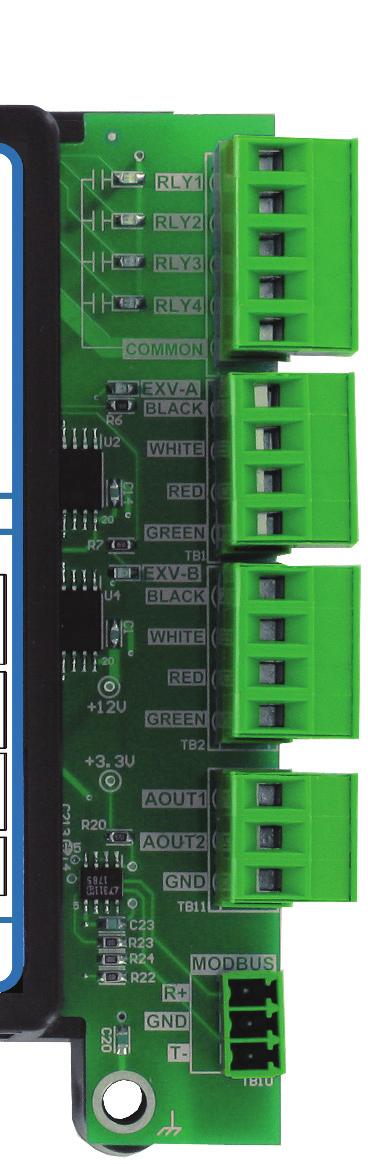
6 WIRING RSMV Inputs Wiring RSMV Wiring The RSMV is connected to the VCC-X or VCCX2 Controller. Up to 4 RSMV s can be connected, depending on the size of the system. There are 2 E-BUS Expansion Ports which allow the use of communicating sensors and the E-BUS Modules. The RSMV provides 4 analog inputs, 3 binary inputs, 3 relays, and 4 analog outputs. See Figure 2, below for inputs wiring and Figure 3, page 7 for outputs wiring. Suction Pressure Sensor Wiring The OE Suction Pressure Transducer must be wired as shown in Figure 2, below. It is required for all compressorized VCC-X / VCCX2 applications. The Suction Pressure Sensor is used to measure suction pressure at the HVAC unit s DX evaporator coil suction line. This suction line pressure is converted to saturated refrigerant temperature by the RSMV Controller. This temperature is used by the RSMV to accurately control the Expansion Valves to maintain Superheat to provide optimum performance of the system. The saturated refrigerant temperature is used to properly control the compressors to maintain a given Suction Coil (Saturated) Temperature Setpoint. In Cooling and Heat Pump mode, the VCC-X / VCCX2 resets the Suction Coil (Saturated) Temperature Setpoint to maintain a given supply air temperature setpoint. In Dehumidification mode, the Suction Coil (Saturated) Temperature Setpoint is a user configurable setpoint that can be reset based on indoor humidity levels. REFRIGERANT SYSTEM MODULE FOR VFD COMPRESSORS (RSMV) SUCTION PRESSURE SENSOR HEAD PRESSURE SENSOR (BY OTHERS) COIL (SUCTION LINE) TEMP. 1 SENSOR COIL (SUCTION LINE) TEMP. 2 SENSOR COMPRESSOR STATUS 1 RD WH BK RD WH BK +V SP +V HP TEMP1 TEMP2 BIN1 BIN2 ALARM OE RSMV REFRIGERANT SYSTEM MODULE V +5 V SP +5 V HP COIL TEMP 1 COIL TEMP 2 TEMP 3 E-BUS SUCTION PRESSURE SENSOR HEAD PRESSURE SENSOR COMP STATUS 1 COMP STATUS 2 NOT USED NOT USED COIL TEMP SENSORS BINARY INPUTS WattMaster Overlay # SW Rev1F M MENU UP ENTER DOWN AAON No.: V42440 RELAY OUTPUT RELAY CONTACT TERMINALS RATING IS 1 AMP COMP 1 24 VAC COMP 2 CONDENSER NOT USED COMMON BLACK EXPANSION WHITE VALVE 1 RED GREEN BLACK EXPANSION WHITE VALVE 2 RED GREEN ANALOG OUTPUTS E-BUS MOD COMP SIG CONDENSER FAN SIG +24 VAC COMPRESSOR STATUS 2 24VAC Size Transformer For Correct Total Load. RSMV = 18 VA Line Voltage Figure 2: RSMV Inputs Wiring 6
7 WIRING RSMV Outputs Wiring CAUTION: The Shraeder port used for installation of the suction pressure transducer should be located in a vertical position of the suction line to prevent refrigerant oil from accumulating in the sensor. Head Pressure Control The RSMV can monitor a Head Pressure Transducer and control Condenser Fans to maintain a Head Pressure Setpoint. The Condenser Fan will be controlled with a 0-10 VDC output signal. Coil Temperature Sensors The Coil Temperature Sensors are used to measure Coil Temperature after each evaporator coil line. This temperature combined with the calculated saturated refrigerant temperature is used to calculate the Superheat of each individual evaporator coil. The Superheat is used to drive the Expansion Valves to maintain a given Superheat Setpoint. Condenser Configuration Options Please see the Appendix on page 25 for Condenser Configuration details. REFRIGERANT SYSTEM MODULE FOR VFD COMPRESSORS (RSMV) NOTE: ALL RELAY OUTPUTS ARE NORMALLY OPEN AND RATED FOR 24 VAC POWER ONLY - 1 AMP MAXIMUM LOAD ALARM RLY1 RLY2 RLY3 24 VAC ONLY COMPRESSOR 1 ENABLE COMPRESSOR 2 ENABLE CONDENSER ENABLE OE RSMV REFRIGERANT SYSTEM MODULE V M MENU UP ENTER DOWN AAON No.: V42440 COMM BK WH RD GRN EXPANSION VALVE 1 +5 V SP +5 V HP COIL TEMP 1 COIL TEMP 2 TEMP 3 E-BUS SUCTION PRESSURE SENSOR HEAD PRESSURE SENSOR COMP STATUS 1 COMP STATUS 2 NOT USED NOT USED COIL TEMP SENSORS BINARY INPUTS WattMaster Overlay # SW Rev1F RELAY OUTPUT RELAY CONTACT TERMINALS RATING IS 1 AMP COMP 1 24 VAC COMP 2 CONDENSER NOT USED COMMON BLACK EXPANSION WHITE VALVE 1 RED GREEN BLACK EXPANSION WHITE VALVE 2 RED GREEN ANALOG OUTPUTS E-BUS MOD COMP SIG CONDENSER FAN SIG +24 VAC AOUT1 AOUT2 BK WH RD GRN + COM EXPANSION VALVE 2 MODULATING COMPRESSOR 24VAC + COM CONDENSER FAN SIGNAL Connect to VCC-X or VCCX2 Controller Line Voltage Size Transformer For Correct Total Load. RSMV = 18 VA Figure 3: RSMV Outputs Wiring 7
8 INPUTS & OUTPUTS RSMV Module Input/Output Maps Zone Zone Input/Output Map See Table 1 for the RSM for VFD Compressor Inputs/Outputs REFRIGERATION SYSTEM MODULE FOR VFD COMPRESSORS Analog Inputs 1 Suction Pressure Sensor (SP) 2 Head Pressure Sensor (HP) 3 4 Coil (Suction Line) Temperature Sensor 1 (TEMP1) Coil (Suction Line) Temperature Sensor 2 (TEMP2) Binary Inputs 1 Compressor Status 1 (BIN1) 2 Compressor Status 2 (BIN2) Analog Outputs (0-10 VDC) 1 Modulating Compressor (AOUT1) 2 Condenser Fan Signal (AOUT2) Stepper Motor Outputs 1 Expansion Valve 1 (EXV-1) 2 Expansion Valve 2 (EXV-2) Binary Outputs (24 VAC) 1 Compressor 1 Enable Relay (R1) 2 Compressor 2 Enable Relay (R2) 3 Condenser Enable Relay (R3) Table 1: RSMV Inputs & Outputs 8
9 INPUTS & OUTPUTS RSMV Inputs & Outputs RSMV - Inputs & Outputs +5V VDC Power This output is a 5 VDC output that supplies power to the Suction Pressure Transducer. SP - Suction Pressure Transducer The Suction Pressure Sensor is used to measure suction pressure at the HVAC unit s DX evaporator coil suction line. This suction line pressure is converted to saturated refrigerant temperature. This temperature combined with the measured temperature of the coil temperature sensors is used to calculate Superheat. The Superheat is used to drive the Expansion Valves to maintain a certain Superheat Setpoint. The saturated refrigerant temperature is also used in the Dehumidification mode of operation to properly control the compressors to maintain a given Suction Coil (Saturated) Temperature Setpoint. +5V VDC Power This output is a 5 VDC output that supplies power to the Head Pressure Transducer. HP - Head Pressure Transducer The Head Pressure Transducer is used to measure Head Pressure at the discharge line. This Head Pressure is used to drive the Condenser Fans to maintain a given Head Pressure Setpoint. TEMP1 & TEMP2 - Coil (Suction Line) Temperature Sensor 1 & Sensor 2 Input These Sensors are used to measure the Coil (Suction Line) Temperature after each evaporator coil line. This temperature combined with the calculated saturated refrigerant temperature is used to calculate the Superheat of each individual evaporator coil. The Superheat is used to drive the Expansion Valves to maintain a given Superheat Setpoint. BIN1 - Compressor Status 1 When this wet contact input closes, a 24 volt signal to Binary Input #1 indicates that Compressor 1 is running. Typically, the source for this is a relay output from the compressor VFD drive. If Binary Input 1 opens, Compressor 1 Enable Relay will de-energize and a Compressor Alarm will be generated. BIN2 - Compressor Status 2 When this wet contact input closes, a 24 volt signal to Binary Input #2 indicates that Compressor 2 is running. Typically, the source for this is a relay output from the auxiliary contact on the compressor starter. If Binary Input 2 opens, Compressor 2 Enable Relay will de-energize and a Compressor Alarm will be generated. NOTE: The Binary Inputs require wet contacts (24 VAC only) to recognize an active input. If you provide dry contacts, the contact closure will not be recognized. AOUT1 - Modulating Compressor Signal This 0-10 VDC output is used to control a Modulating Compressor to maintain the Cooling Supply Air Temperature Setpoint. AOUT2 - Condenser Fan VFD Signal This is a direct acting output signal that is used to modulate the Condenser Fan VFD (0-10 VDC signal) on an Air Cooled unit. EXV-1 The Electronic Expansion Valve 1 is driven to maintain Superheat for Evaporator Coil 1 of its particular refrigerant system. EXV-2 The Electronic Expansion Valve 2 is driven to maintain Superheat for Evaporator Coil 2 of its particular refrigerant system. RLY1 - Compressor 1 Enable This relay turns on the Modulating Compressor. RLY2 - Compressor 2 Enable This relay turns on the Fixed Compressor. RLY3 - Condenser Enable This relay turns on the Condenser Fan / Water Valve. 9
10 Zone SEQUENCE OF OPERATIONS Cooling Mode & Dehumidification Operation Zone Cooling Mode Operation Dehumidification Operation In the Cooling Mode, as the Supply Air Temperature (SAT) rises above the Active SAT Cooling Setpoint, the compressors will stage on and modulate to maintain the Active Evaporator Coil Suction (Saturated) Temperature Setpoint. One set of tandem compressors (a VFD compressor and a fixed stage compressor) are controlled per Refrigerant System Module-VFD Compressor (RSMV). Multiple RSMVs are needed for multiple sets of tandem compressors In units with one set of tandem compressors, if the VFD compressor modulates to 100% and the SAT is still above the SAT Cooling Setpoint for the Cooling Stage Up Delay, then the fixed compressor will stage on. The VFD compressor will then be allowed to modulate as necessary to maintain the Active Evaporator Coil Suction (Saturated) Temperature Setpoint. Minimum off times must also be met before compressors can stage on. To stage down compressors, if the VFD compressor(s) have modulated down to 30% for the Stage Down Delay period and the SAT has fallen below the SAT Cooling Setpoint minus the Stage Control Window, then the last compressor to have staged on (VFD or Fixed) will stage off assuming its Minimum Run Time has been met. Any remaining VFD compressors are then allowed to modulate as needed. If the last remaining VFD compressor reaches 0% for the Stage Down Delay, it will stage off. Once in Dehumidification Mode, units with fixed compressors will activate the compressors to maintain the Evaporator Coil Suction (Saturated) Temperature Setpoint. An RSMV Module will be required for each fixed compressor or each fixed compressor tandem pair in order to monitor the suction (saturated) temperature and control the compressor(s) accordingly. Each RSMV will independently activate and stage its compressor(s) to maintain that circuit s Suction (Saturated) Temperature Setpoint. The staging of compressors on an RSMV is subject to Stage Up and Stage Down Delays as well as compressor Minimum Run Times and Minimum Off Times. A suction pressure transducer is used and the VCC-X / VCCX2 Controller converts that to a Suction (Saturated) Temperature value On units with one or more sets of VFD/Fixed tandem compressors, each set of tandem compressors (one circuit) will be controlled by a separate RSMV Module with its own Suction Pressure Transducer (converted to a Suction (Saturated) Temperature). Once the unit enters the Dehumidification Mode, each RSMV will initially activate the VFD compressor as required to maintain the Suction (Saturated) Temperature Setpoint. At that point each RSMV will modulate its VFD compressor and enable the fixed compressor, as necessary, to maintain the Suction (Saturated) Temperature Setpoint for that circuit. If the VFD compressor reaches 100% for the Stage Up Delay and the Suction (Saturated) Temperature is still above setpoint, then the fixed compressor will stage on while the VFD compressor modulates as needed. If the VFD compressor has modulated down to 0% and the Suction (Saturated) Temperature is 5 degrees below the Suction (Saturated) Temperature for the Stage Down Delay period, the fixed compressor will stage off and the VFD compressor will continue to modulate. During this operation, compressor Minimum Run Times and Minimum Off Times must be met. SAFETY: If the Coil Temperature drops below 32 F, any cooling remaining on will be forced to stage off. 10
11 SEQUENCE OF OPERATIONS Electronic Expansion Valve Operation & Head Pressure Control Electronic Expansion Valve (EXV) Operation If EXV s are being used, a Coil (Suction Line) Temperature Sensor will measure the Coil (Suction Line) Temperature after each Evaporator Coil line for each compressor, and this sensor will be connected to an RSMV Module. This temperature will be used in conjunction with the calculated saturated refrigerant temperature to calculate the Superheat of each evaporator coil. The EXV for each coil will then be controlled to maintain the Superheat Setpoint. Head Pressure Control The Refrigeration System Module for VFD Compressors (RSMV) can monitor a Head Pressure Transducer and control a Condenser Fan to maintain a Head Pressure Setpoint. The RSMV must be configured for an Air Cooled Condenser. A Condenser Relay is commanded on when the first compressor is enabled (except if the unit is in Heat Pump Defrost Mode). On an Air Cooled Unit, the Condenser Fan will be controlled with 0-10 VDC output signal. When the Condenser Signal first activates, it maintains at 100% for 10 seconds. In the Cooling Mode, the Condenser Signal will modulate to maintain the Cooling Head Pressure Setpoint. The signal can modulate between 15% and 100%. If the Head Pressure exceeds 550 PSIG, the condenser control signal will immediately go to 100% and a High Head Pressure Alarm will be generated. The alarm will be deactivated when the Head Pressure drops below 540 PSIG. In the Dehumidification Mode, the Condenser Output Signal controls to the Reheat Head Pressure Setpoint. High Head Pressure conditions produce the same effects as in the Cooling Mode. If no Head Pressure Sensor is detected, the Condenser the Condenser Output Signal will be maintained at 100%. 11
12 RSMV LCD SCREENS LCD Display Screen & Navigation Keys LCD Display Screen & Navigation Keys The LCD display screens and buttons allow you to view status and alarms, and enable force modes. See Figure 4, below and refer to Table 2 for descriptions. NAVIGATION KEY MENU UP KEY FUNCTION Use the MENU key to move through screens within Main Menu categories and return to the Main Menu while at other screens. Use this key to adjust setpoints and change confi gurations. DOWN Use this key to adjust setpoints and change confi gurations. ENTER Use the ENTER key to navigate through the Main Menu Screen categories. Figure 4: LCD Display and Navigation Keys Table 2: Navigation Key Functions 12
13 RSMV LCD SCREENS Main Screen Map & RSMV Module Screens RSMV Main Screens Map Refer to the following map when navigating through the LCD Main Screens. To scroll through the screens, press the <MENU> button. RSMV 1072vXXX RSMV Module Screens Refer to the following map when navigating through the RSMV Screens. From the RSMV MODULE Screen, press <ENTER> to scroll through the screens. RSMV 1072vXXX Press to scroll through REFRIG MODULE Screens. Press Press to go to SYSTEM STATUS Screens. SYSTEM STATUS to scroll through SYSTEM STATUS Screens. E-BUS # E-BUS COMMUNICATION DIAGNOSTICS Number of COMM packets received. Press to go to SENSOR STATUS Screen. SENSOR STATUS SOFTWARE 1072vXXX Press Press to scroll through SENSOR STATUS Screens. to go to ALARMS Screens. CURRENT SOFTWARE VERSION You can access the protected screens from this screen by holding the <UP> button for 5 seconds. Press ALARMS to scroll through ALARMS Screens. ADDRESS # Press Press to go to ALARM HISTORY Screens. ALARM HISTORY to scroll through ALARM HISTORY Screens. CURRENT BOARD ADDRESS SYS TYPE COOL ONLY Press to go to SETPOINT STATUS Screens. CURRENT SYSTEM TYPE Press SETPOINT STATUS to scroll through SETPOINT STATUS Screens. #OF COMP # # OF COMPRESSORS 13
14 RSMV LCD SCREENS System Status Screens #OF EXVs # # OF EXPANSION VALVES COMP A1-D1 OFF/ MODULATING % COMPRESSOR A1, B1, C1, D1 (based on board address) OFF / MOD POSITION OFF: Compressor is off. MODULATING PERCENTAGE: 0-100% COMP A1 MOD OR FIXED COMPRESSOR A1 STATUS COMP A2-D2 ON/OFF # OF COND 1 or 0 COMPRESSOR A2, B2, C2, D2 (based on board address) ON, OFF, FORCE ON: Compressor is on. OFF: Compressor is off. # OF CONDENSERS COND FAN NOT USED/OFF/ MODULATING % System Status Screens Refer to the following map when navigating through the System Status Screens. From the SYSTEM STATUS Screen, press <ENTER> to scroll through the screens. CONDENSER FAN NOT USED, OFF, MOD POSITION OFF: Condenser is off. MODULATING PERCENTAGE: 0-100% SYSTEM STATUS EXV A1-D1 0% MODE EXV A1, B1, C1, D1 (based on board address) EXV VALVE POSITION 0 to 100 percent SYSTEM MODE Possible choices are OFF, COOL, HEAT, DEHUMID, FORCE EXV A2-D2 0% EXV A2, B2, C2, D2 (based on board address) EXV VALVE POSITION 0 to 100 percent 14
15 RSMV LCD SCREENS Sensor Status & Setpoint Status Screens Sensor Status Screens Refer to the following map when navigating through the Sensor Status Screens. From the SENSOR STATUS Screen, press <ENTER> to scroll through the screens. SENSOR STATUS COIL 2 XX DEG COIL TEMPERATURE 2 READING FROM TEMPERATURE SENSOR INPUT SUCTION XXX PSI SUCTION PRESSURE READING FROM INPUT CALC CT XX DEG CALCULATED COIL TEMPERATURE FROM SUCTION PRESSURE INPUT HEAD XXX PSI HEAD PRESSURE READING FROM INPUT Setpoint Status Screens Refer to the following map when navigating through the Setpoint Status Screens. From the SETPOINT STATUS Screen, press <ENTER> to scroll through the screens. SETPOINT STATUS SUPRHT 1 XX DEG CURRENT SUPERHEAT 1 CALCULATION HEADPR SP 340 PSI SUPRHT 2 XX DEG HEAD PRESSURE SETPOINT Valid range is 275 to 475 PSI. Default is 340 PSI. CURRENT SUPERHEAT 2 CALCULATION SPRHT SP 15 COIL 1 XX DEG SUPERHEAT SETPOINT SETTING Valid range is 1 to 30 degrees. Default is 15 degrees. COIL TEMPERATURE 1 READING FROM TEMPERATURE SENSOR INPUT 15
16 RSMV LCD SCREENS Setpoint Status Screens & Alarms Screen COILT SP 40 COIL TEMPERATURE SETPOINT SETTING Valid range is 35 to 70 degrees. Default is 40 degrees. Alarms Screen LOW SUCT 95 psi LOW SUCTION PRESSURE SETPOINT SETTING Default is 95 PSI. If an alarm is present, the ALARM LED above the LCD display will light up red and blink. The Alarms will display and scroll automatically from the ALARMS screen when alarms are present. ALARMS COIL TEMP A2 FAILURE: This alarm will occur if the coil temperature is not within operable range (below -32F or above 310F). This could be the result of a bad sensor or faulty wiring. This alarm will shut down the system. The system will reset after 5 minutes if the sensor is detected. COMPRESSOR (COMP) A1 FAILURE: This alarm will occur if the compressor fails to run 45 seconds after the relay is activated or if the signal is lost after activation. This will cause an alarm and will shut down the compressor (relay). The system will retry after 5 minutes. COMPRESSOR (COMP) A2 FAILURE: This alarm will occur if the compressor fails to run 45 seconds after the relay is activated or if the signal is lost after activation. This will cause an alarm and will shut down the compressor (relay). The system will retry after 5 minutes. LOW SUPERHEAT 1 (SH1) DETECTED: This alarm will be activated when the Superheat is less than 4 degrees for 2 minutes during normal operation or for 4 minutes during the fi rst 10 minutes. The system will shut down and will retry after 5 minutes. LOW SUPERHEAT 2 (SH2) DETECTED: This alarm will be activated when the Superheat is less than 4 degrees for 2 minutes during normal operation or for 4 minutes during the fi rst 10 minutes. The system will shut down. The system will shut down and will retry after 5 minutes. HIGH SUPERHEAT 1 (SH1) WARNING: If superheat is above 25 degrees for 2 minutes, this alarm will appear on the module only. It will not be sent to the main controller to display on Prism 2. HIGH SUPERHEAT 2 (SH2) WARNING: If superheat is above 25 degrees for 2 minutes, this alarm will appear on the module only. It will not be sent to the main controller to display on Prism 2. HIGH SUPERHEAT 1 (SH1) FAILURE: If superheat is above 30 degrees for 10 minutes, it will fail the compressors. It will retry after 5 minutes. If it fails twice in 2 hours, it will lock out the compressors. The alarms are as follows: NO ALARMS: This will be shown if there are no current alarms. NO SUCTION PRESSURE SENSOR (SUCT) DETECTED: This alarm indicates the Suction Pressure Sensor is not detected by the system. The system will shut down due to Unsafe Suction safety and will retry after 5 minutes. HIGH HEAD PRESSURE (HP) DETECTED: This indicates a High Head Pressure Alarm condition which is activated when the Head Pressure rises above 550 PSIG. This will cause the condenser to go to 100%. NO HEAD PRESSURE SENSOR (HEAD) DETECTED: This alarm indicates the Head Pressure Sensor is not detected by the system. This will cause the condenser to go to 100%. COIL TEMP A1 FAILURE: This alarm will occur if the coil temperature is not within operable range (below -32F or above 310F). This could be the result of a bad sensor or faulty wiring. This alarm will shut down the system. The system will reset after 5 minutes if the sensor is detected. HIGH SUPERHEAT 2 (SH2) FAILURE: If superheat is above 30 degrees for 10 minutes, it will fail the compressors. It will retry after 5 minutes. If it fails twice in 2 hours, it will lock out the compressors. HIGH SUPERHEAT LOCKOUT: If the module fails on high superheat twice in 2 hours, it will lock out the compressors. LOW SUCTION PRESSURE (SP) DETECTED: This alarm will occur if suction pressure falls below the low suction pressure setpoint for 20 seconds. The system will try to protect by lowering compressor modulation percentage. LOW SUCTION PRESSURE FAILURE: This alarm will occur if suction pressure stays below the low suction pressure setpoint for 1 minute or falls below 40 psi for 5 seconds. This alarm will shut down the system. The system will retry after 5 minutes. EBUS SLAVE (SLV) TIMEOUT: This alarm indicates that communication has been lost between the RSMV and the Main controller or other E-BUS modules that may be connected. This can be the result of a bad cable, a missing cable, or the module not being confi gured properly. 16
17 RSMV LCD SCREENS Alarm History & Protected Screens Alarm History Screens The ALARM HISTORY Screen displays past alarms, if any, and how long ago the last of each type occurred. From the ALARM HISTORY Screen, press <ENTER> to scroll through the history screens. ALARM HISTORY Protected Screens Map Refer to the following map when navigating through the LCD Protected Screens. From the RSMV Screen, press <ENTER> twice to get to the Software Screen. Then hold the <UP> button for 5 seconds. To scroll through the rest of the screens, press the <MENU> button. RSMV 1072vXXX The Alarm will appear on the first line and the second line will display how long ago each alarm last occurred. As a result, the alarms listed on the ALARMS screen will be abbreviated as follows in order of the way they are listed in the prior ALARMS screen section. E-BUS +0 LOW SP Low Suction Pressure UNSAFE SP Unsafe Suction Pressure SP SENSE No Suction Pressure Sensor Detected HIGH HP High Head Pressure HP SENSE No Head Pressure Sensor Detected CL TEMP 1 Coil Temp 1 Failure CL TEMP 2 Coil Temp 2 Failure COMP 1 FL Compressor 1 Failure COMP 2 FL Compressor 2 Failure LOW SH1 Low Superheat 1 LOW SH2 Low Superheat 2 HI SH1 High Superheat 1 Failure HI SH2 High Superheat 2 Failure COMM T/0 E-BUS Slave Timeout Hold SOFTWARE 1072v101 for 5 seconds. DIAGNSTC ALARM COUNTS NOTE: The screen will display minutes for the first 60 minutes of alarm occurrence, hours for the next 72 hours of alarm occurrence, and days for the next 30 days of alarm occurrence. After 30 days, the alarm will clear. Alarm history is not stored in memory. So, if power VFD TEST ADDRESS 1(152) ENTER TO EXIT 17
18 RSMV LCD SCREENS Diagnostic Screens Diagnostic Screens Refer to the following map when navigating through the Diagnostic Screens. From the DIAGNSTC Screen, press <ENTER> to scroll through the screens. DIAGNSTC SP-A VLT X.XX SUCTION PRESSURE SENSOR VOLTAGE Displays the current voltage of the Suction Pressure Sensor. WDOG CNT # WATCH DOG TIMER Displays the number of times the board has been reset due to watchdog timer overflow. HP-A VLT X.XX HEAD PRESSURE SENSOR VOLTAGE Displays the current voltage of the Head Pressure Sensor. PWER CNT # POWER LOSS COUNT Displays the number of times the board has been reset due to power loss. BIN 1 - BIN 4 ON/OFF BINARY INPUTS #1 - #4 Displays the current status of each Binary Input. EPROM: HOLD DOWN TO TMP1 VLT X.XX COIL TEMPERATURE SENSOR 1 VOLTAGE Displays the current voltage of the 1st Coil Temperature Sensor. LOAD DEFAULTS TMP2 VLT X.XX COIL TEMPERATURE SENSOR 2 VOLTAGE Displays the current voltage of the 2nd Coil Temperature Sensor. 18
19 RSMV LCD SCREENS Diagnostic Screens TMP5 VLT X.XX AOUT-2 V vdc TEMPERATURE SENSOR 5 VOLTAGE (NOT USED) CONDENSER FAN FORCE MODE 1.0 to 10.0 = Active Force Mode. Press the <UP> and <DOWN> buttons to increase and decrease the value. FORCE MODE ON/OFF FORCE MODE Displays the current status of Force Mode. Values are ON/OFF. EXV 1-4 % #% EXPANSION VALVES OPEN PERCENTAGE 1.0 to 10.0 = Active Force Mode. Press the <UP> and <DOWN> buttons to increase and decrease the value. If forced on, the following screens will appear: RLY 1-4 ON/OFF ENTER TO EXIT RELAYS 1-4 FORCE MODE Press the <UP> and <DOWN> buttons to select ON or OFF for each relay AOUT-1 V vdc ALARM COUNTS Screens From the ALARM COUNTS Screen, press <ENTER> to scroll through the screens. Each screen will display the name of the alarm and how many times the alarm has occurred since you last cleared the alarms. The only way to clear these alarm counts is by using Prism 2 and selecting, Select Alarms to Delete from the ALARM button menu. See Alarm Polling in the Prism 2 Technical Guide for more information. MODULATING COMPRESSOR FORCE MODE 0.0 to 10.0 = Active Force Mode. Press the <UP> and <DOWN> buttons to increase and decrease the value. 19
20 RSMV LCD SCREENS VFD Test Screens & Address Screen Zone Zone VFD Test Screens Address Screen Refer to the following map when navigating through the VFD Test Screens. VFD test screens are only used when VFD is connected via MODBUS communications. From the VFD TEST Screen, press <ENTER> to scroll through the screens. VFD TEST ENABLED/ DISABLED VFD COMPRESSOR TEST Values are Enable or Disabled. ADDRESS 1(152) CURRENT BOARD ADDRESS Confi gure the address according to which refrigerant circuit this module represents 1=A, 2=B, 3=C, 4=D Number in parentheses is E-BUS address. Module 1 s address is 152, Module 2 s address is 153, Module 3 s address is 154, Module 4 s address is 155 VFD FREQ 0.0 HZ VFD COMPRESSOR FREQUENCY Current VFD Frequency. Values are 0.0 HZ to VFD VOLT 0.0 VFD COMPRESSOR VOLTAGE Current VFD Voltage. VFD AMPS 0 VFD COMPRESSOR AMPS Current VFD Amps. 20
21 TROUBLESHOOTING RSMV LED Diagnostics Using RSMV LEDs To Verify Operation The RSMVs are equipped with LEDs that can be used to verify operation and perform troubleshooting. There are LEDs for communication, operation modes, and diagnostic codes. See Figure 5, below for the LED locations. The LEDs associated with these inputs and outputs allow you to see what is active without using a voltmeter. The LEDs and their uses are as follows: Diagnostic LEDs STATUS - If the software is running, this LED should blink at a rate of 1 blink per second. ALARM (on board) - If the module does not receive communications for more than 1 minute, this LED will light up, the relays will turn off, and the Analog Outputs will go to 0 VDC. ALARM (above LCD display) This red LED will light up and stay lit when there is an alarm present. The type of alarm will display on the LCD display. The ALARM LED also blinks when the expansion valve is initializing at startup. COMM - Every time the module receives a valid E-BUS request from the VCC-X / VCCX2 Controller, this LED will blink on and then off, signifying that it received a valid request and responded. POWER - This LED will light up to indicate that 24 VAC power has been applied to the controller. Binary Input LEDs BIN1 - This green LED will light up when Compressor Status 1 contact is closed. BIN2 - This green LED will light up when Compressor Status 2 switch is closed. BIN3 - This green LED will light up when the Outside Coil Temperature switch is closed. Relay LEDs RLY1 - RLY4 - These green LEDs will light up when the relays are enabled and will stay lit as long as they are active. RSMV Stepper Motor Valve LEDs EXV-1 - This green LED will light up when Expansion Valve 1 is modulating. EXV-2 - This green LED will light up when Expansion Valve 2 is modulating. ALARM LED RSMV STATUS ALARM COMM POWER LEDs ALARM M MENU UP ENTER RELAY LEDs EXV-1 LED OE RSMV REFRIGERANT SYSTEM MODULE V DOWN AAON No.: V42440 BINARY INPUT LEDs +5 V SP +5 V HP COIL TEMP 1 COIL TEMP 2 TEMP 3 E-BUS SUCTION PRESSURE SENSOR HEAD PRESSURE SENSOR COMP STATUS 1 COMP STATUS 2 NOT USED NOT USED COIL TEMP SENSORS BINARY INPUTS WattMaster Overlay # SW Rev1F RELAY OUTPUT RELAY CONTACT TERMINALS RATING IS 1 AMP COMP 1 24 VAC COMP 2 CONDENSER NOT USED COMMON BLACK EXPANSION WHITE VALVE 1 RED GREEN BLACK EXPANSION WHITE VALVE 2 RED GREEN ANALOG OUTPUTS E-BUS MOD COMP SIG CONDENSER FAN SIG +24 VAC EXV-2 LED Figure 5: RSMV LED Locations 21
22 TROUBLESHOOTING Zone OE Suction Pressure Transducer Testing Zone OE Suction Pressure Transducer Testing for R410A Refrigerant The Evaporator Coil Temperature is calculated by converting the Suction Pressure to Temperature. The Suction Pressure is obtained by using the OE Suction Pressure Transducer, which is connected into the Suction Line of the Compressor. Use the voltage column to check the Suction Pressure Transducer while connected to the RSMV Module(s). The VCC-X / VCCX2 and the RSMV Module(s) must be powered for this test. Read voltage with a meter set on DC volts. Place the positive lead from the meter on the SP terminal located on the RSMV Module(s) terminal block. Place the negative lead from the meter on the ground () terminal located adjacent to the SP terminal on the RSMV Module(s) terminal block. Use a refrigerant gauge set and/or an accurate electronic thermometer to measure the temperature or suction line pressure near where the Suction Pressure Transducer is connected to the suction line. Measure the Voltage at the SP and terminals and compare it to the appropriate chart depending on the refrigerant you are using. If the temperature/voltage or pressure/voltage readings do not align closely with the chart, your Suction Pressure Transducer is probably defective and will need to be replaced. See the OE Suction Pressure Transducer, Pressure, Temperature, and Voltage Chart for R410A Refrigerant testing. The charts show a temperature range from 20 F to 80 F. For troubleshooting purposes, the DC Voltage readings are also listed with their corresponding temperatures and pressures. Temperature F OE Suction Pressure Transducer Coil Pressure Temperature Voltage Chart for R410A Refrigerant Pressure PSI Signal DC Volts Temperature F Pressure PSI Signal DC Volts Table 3: Coil Pressure/Voltage/Temp for OE Suction Pressure Transducers - R410A Refrigerant 22
23 TROUBLESHOOTING Temperature Sensor Testing Coil Temperature Sensor Testing The following sensor voltage and resistance table is provided to aid in checking sensors that appear to be operating incorrectly. Many system operating problems can be traced to incorrect sensor wiring. Be sure all sensors are wired per the wiring diagrams in this manual. If the sensors still do not appear to be operating or reading correctly, check voltage and/or resistance to confirm that the sensor is operating correctly per the tables. Please follow the notes and instructions that appear after the chart when checking sensors. Temperature Resistance Voltage for Type III 10 K Ohm Thermistor Sensors Temp (ºF) Temp (ºC) Resistance (Ohms) Input (VDC) Temperature Resistance Voltage for Type III 10 K Ohm Thermistor Sensors Temp (ºF) Temp (ºC) Resistance (Ohms) Input (VDC) Table 4, cont.: Temperature/Resistance for Type III 10K Ohm Thermistor Sensors Thermistor Sensor Testing Instructions Use the resistance column to check the thermistor sensor while disconnected from the controllers (not powered). Use the voltage column to check sensors while connected to powered controllers. Read voltage with meter set on DC volts. Place the - (minus) lead on terminal and the + (plus) lead on the sensor input terminal being investigated. If the voltage is above 4.88 VDC, then the sensor or wiring is open. If the voltage is less than 0.05 VDC, then the sensor or wiring is shorted. Table 4: Temperature/Resistance for Type III 10K Ohm Thermistor Sensors 23
24 TROUBLESHOOTING Zone Head Pressure Transducer Troubleshooting Zone Head Pressure Transducer Troubleshooting If you suspect there is a problem related to the head pressure transducer, measurements can be taken at the HP terminal. Reference Table 5, below. Head Pressure Transducer Chart Voltage Pressure Voltage Pressure Table 5: Head Pressure Transducer Chart 24

25 APPENDIX: CONDENSER OPTIONS Single Condenser Per 1 Module Single Condenser Per 1 Module In Single Condenser Per 1 Module wiring configuration, the Condenser Signal is wired to AO2 and the Condenser Relay RLY3 is enabled. Refer to the figures below for Prism 2 configuration and Modular Service Tool Screen selection. Figure 6: Prism 2 Condenser Configuration RSMV & RSMV-HP Condenser Options Configuration Screen RSM#1-4 CONFIGURATION Condenser Options 1 Cond per 1 RSMV USE < or > TO CHANGE Select the 1 Condenser per 1 RSMV option on the above Hand Held Service Tool Screen. 25

26 APPENDIX: CONDENSER OPTIONS Single Condenser Per Two Modules Single Condenser Per 2 Modules In Single Condenser Per 2 Modules wiring configuration, if using 2 modules, the Condenser Signal is wired to AO2 on the 1st module but not the 2nd module and the Condenser Relay RLY3 is enabled on the 1st module but not the 2nd module. If using 4 modules, the Condenser Signal is wired to AO2 on the 1st and 3rd modules but not the 2nd and 4th modules and the Condenser Relay RLY3 is enabled on the 1st and 3rd modules but not the 2nd and 4th modules. Refer to the figures below for Prism 2 configuration and Modular Service Tool Screen selection. Figure 7: Prism 2 Condenser Configuration RSMV & RSMV-HP Condenser Options Configuration Screen RSM#1-4 CONFIGURATION Condenser Options 1 Cond per 2 RSMVs USE < or > TO CHANGE Select the 1 Condenser per 2 RSMVs option on the above Hand Held Service Tool Screen. 26

27 APPENDIX: CONDENSER OPTIONS Single Condenser for Three Modules Single Condenser for 3 Modules In Single Condenser for 3 Modules wiring configuration, the Condenser Signal is wired to AO2 on the 1st module but not the 2nd & 3rd modules and the Condenser Relay RLY3 is enabled on the 1st module but not the 2nd & 3rd modules. Refer to the figures below for Prism 2 configuration and Modular Service Tool Screen selection. Figure 8: Prism 2 Condenser Configuration RSMV & RSMV-HP Condenser Options Configuration Screen RSM#1-4 CONFIGURATION Condenser Options 1 Cond for 3 RSMVs USE < or > TO CHANGE Select the 1 Condenser for 3 RSMVs option on the above Hand Held Service Tool Screen. 27
28 APPENDIX: CONDENSER OPTIONS Single Condenser for Four Modules Zone Zone Single Condenser for 4 Modules In Single Condenser for 4 Modules wiring configuration, the Condenser Signal is wired to AO2 on the 1st module but not the 2nd, 3rd, or 4th modules and the Condenser Relay RLY3 is enabled on the 1st module but not the 2nd, 3rd, or 4th modules. Refer to the figures below for Prism 2 configuration and Modular Service Tool Screen selection. Figure 9: Prism 2 Condenser Configuration RSMV & RSMV-HP Condenser Options Configuration Screen RSM#1-4 CONFIGURATION Condenser Options 1 Cond for 4 RSMVs USE < or > TO CHANGE Select the 1 Condenser for 4 RSMVs option on the above Hand Held Service Tool Screen. 28

29 APPENDIX A - SYSTEM CONFIGURATIONS System Configurations System Configuration Using Prism 2 Refer to Figure 10 below in setting RSMV configuration options. Figure 10: Prism 2 RSMV Configuration Screen Single Compressor Configuration Select this configuration if the RSMV only has one Compressor wired to it. If there are two Compressors, leave this selection blank. Single Evaporator Coil Configuration Select this configuration if the RSMV only has one Expansion Valve wired to it. If there are two Expansion Valves, leave this selection blank. Fixed Compressors Configuration Select this configuration if the RSMV only has Fixed Compressors wired to it. If the first Compressor is Modulating, leave this selection blank. Single Condenser Coil Expansion Valve Configuration This configuration only applies when using the RSMV-HP. Select this configuration when Expansion Valve 3 is wired and Expansion Valve 4 is not wired. If both are connected, leave this selection blank. Copeland VFD Configuration Select this configuration if the RSMV is controlling a Copeland VFD through the MODBUS connection. Single Compressor Startup Select this configuration if the desired startup routine enables one compressor at a time on the system. Leaving this blank makes the first compressor on each module enabled at startup which is the default method. Most systems require the first compressor on each module to be enabled to achieve the full evaporator coil face active. 29
30 NOTES 30
31 NOTES 31
32 2425 So. Yukon Ave Tulsa, OK Ph: (918) Fax: (918) AAON Part No.: V87390 WM Form: AA-RSMV-TGD-01B Printed in the USA Copyright August 2017 All Rights Reserved WattMaster Controls, Inc NW River Park Drive Parkville, MO 64152
RSMSD Technical Guide
 RSMSD Technical Guide www.aaon.com AAON/WattMaster Controls Inc. 8500 NW River Park Drive Parkville, MO 64152 Toll Free Phone: 866-918-1100 PH: (816) 505-1100 FAX: (816) 505-1101 E-mail: mail@wattmaster.com
Factory Packaged Controls. MHGRV-X Controller Field Technical Guide
 Factory Packaged Controls MHGRV-X Controller Field Technical Guide TABLE OF CONTENTS CONTROLLER OVERVIEW... 3 Features...3 INSTALLATION & WIRING... 4 Important Wiring Considerations...5 MHGRV-X Controller
Water Source Heat Pump Module Technical Guide
 Factory Packaged Controls Tulsa Water Source Heat Pump Module WSHP WSHP Protection Module Module Orion No.: OE334-23-WPM-A NON-DIGITAL COMPRESSORS #1 THRU #4 +5V SUCT. +5V SUCTION PR. SENSOR PRES PRES
Factory Packaged Controls. MHGRV-X Controller Field Technical Guide
 Factory Packaged Controls MHGRV-X Controller Field Technical Guide TABLE OF CONTENTS CONTROLLER OVERVIEW... 3 Features... 3 INSTALLATION & WIRING... 4 Important Wiring Considerations... 4 MHGRV-X Controller
VCM-X Controller Technical Guide
 2 2 www.orioncontrols.com VCM-X Controller Technical Guide VCM-X Controller Code: SS1026 & Y200920 Version 2.0 and up; VCM-X Modular Controller: Tulsa - SS1030; Coil - SS1034 VCM-X WSHP Controller: Tulsa
VCC-X Controller Technical Guide
 VCC-X Controller Technical Guide VCC-X Controller Code: SS1079 Version 1.0 and up Requires Service Tool SD Code: SS1063 Version 1.0 and up Requires System Manager SD Code: SS1068 Version 1.11 and up Requires
VCM-X Modular E-BUS Controller Technical Guide
 www.orioncontrols.com VCM-X Modular E-BUS Controller Technical Guide VCM-X Modular E-BUS Controller: Tulsa - SS1030; Coil - SS1034 VCM-X WSHP E-BUS Controller: Tulsa - SS1032; Coil - SS1033 Requires Service
Refrigeration Controller Operator s Manual (HRC) PO Box 6183 Kennewick, WA
 PO Box 6183 Kennewick, WA") Refrigeration Controller Operator s Manual (HRC) PO Box 6183 Kennewick, WA 99336 www.jmcvr.com 1-509-586-9893 Table of Contents TABLE OF FIGURES...1 OVERVIEW OF THE HRC CAPABILITIES...2 INSTALLATION AND
Refrigeration Controller Operator s Manual (HRC) PO Box 6183 Kennewick, WA 99336 www.jmcvr.com 1-509-586-9893 Table of Contents TABLE OF FIGURES...1 OVERVIEW OF THE HRC CAPABILITIES...2 INSTALLATION AND
VCB-X Modular Service Tool Technical Guide. VCB-X Controller Code: SS1051 Version 2.0 Requires Service Tool Code: SS1041 Version 2.
 VCB-X Modular Service Tool Technical Guide VCB-X Controller Code: SS1051 Version 2.0 Requires Service Tool Code: SS1041 Version 2.0 and up Table of Contents INTRODUCTION... 3 Modular Service Tool...3 SYSTEM
Pioneer Gold Controller Technical Guide
 Pioneer Gold Controller Technical Guide Pioneer Gold Controller Code: Version 1.03 Electric Heat Expansion Module Code: Version 1.0 Used with AAON WSHP WV Series Vertical and WH Series Horizontal This
VCM-X / RNE Controller Operator Interface SD Technical Guide
 VCM-X / RNE Controller Operator Interface SD Technical Guide VCM-X Controller Code: SS1026 VCM-X E-BUS Controller Codes: SS1030, SS1032, SS1033, SS1034 RNE Controller Code: SS1045 VAV/Zone Controller Code:
VCCX2 Controller Operator Interface SD Technical Guide
 www.orioncontrols.com VCCX2 Controller Operator Interface SD Technical Guide VCCX2 Controller Code: SS1088 Version 1.0 & up VAV/Zone Controller Code: SS8011 Requires Service Tool SD Code: SS1063 Requires
VCM-X / RNE Operator Interfaces Technical Guide
 Factory Packaged Controls VCM-X / RNE Operator Interfaces Technical Guide VCM-X Controller Code: SS1026, SS1030, SS1032, SS1033, SS1034 Requires System Manager Code: SS1028 Version 1.0 and up Requires
FOR SERVICE TECHNICIAN S USE ONLY
 F SERVICE TECHNICIAN S USE ONLY NOTE: This sheet contains important Technical Service Data. Tech Sheet Do Not Remove Or Destroy DANGER Electrical Shock Hazard Only authorized technicians should perform
Digital Precise Air Control - DPAC
 Digital Precise Air Control - DPAC Mode Enable Sensor Options The temperature of this sensor will determine if the unit is in heating, cooling or vent mode during Occupied operation. The following options
Application and Installation Bulletin for Master-Bilt Refrigeration Superheat Controller Kit Assembly(A ), 120/208/240/1/60, R404A, LT/MT APPS
, 120/208/240/1/60, R404A, LT/MT APPS") Application and Installation Bulletin for Master-Bilt Refrigeration Superheat Controller Kit Assembly(A900-22007), 120/208/240/1/60, R404A, LT/MT APPS Introduction The superheat controller is designed
Application and Installation Bulletin for Master-Bilt Refrigeration Superheat Controller Kit Assembly(A900-22007), 120/208/240/1/60, R404A, LT/MT APPS Introduction The superheat controller is designed
FOR SERVICE TECHNICIAN S USE ONLY
 FOR SERVICE TECHNICIAN S USE ONLY NOTE: This sheet contains important Technical Service Data. Tech Sheet Do Not Remove Or Destroy DANGER Electrical Shock Hazard Only authorized technicians should perform
RNE Modular Controller Technical Guide
 Factory Packaged Controls RNE Modular Controller Technical Guide RNE Modular Controller: Tulsa - SS1045 Requires Service Tool Code: SS1056 Version 1.0 and up RS-485 COMMUNICATION LOOP. WIRE R TO R, T TO
VCCX2 Controller Operator Interface SD Technical Guide
 www.orioncontrols.com VCCX2 Controller Operator Interface SD Technical Guide VCCX2 Controller Code: SS1088 Version 1.0 & up VAV/Zone Controller Code: SS8011 Requires Service Tool SD Code: SS1063 Requires
Pioneer Gold Controller Technical Guide. Pioneer Gold Controller Code: Version 1.1 Used with AAON WSHP WV Series Vertical and WH Series Horizontal
 Pioneer Gold Controller Technical Guide Pioneer Gold Controller Code: Version 1.1 Used with AAON WSHP WV Series Vertical and WH Series Horizontal WARNING QUALIFIED INSTALLER IMPROPER INSTALLATION, ADJUSTMENT,
TWLC - Tempered Water Logic Controller. The Intelligent Control
 TWLC - Tempered Water Logic Controller The Intelligent Control Chiller Controls Features: Up to six (6) stages: individual board for each stage maximizes redundancy. Menu driven access and programming.
DXM2 Digital Heat Pump Controller
 APPLICATION, OPERATION & MAINTENANCE MANUAL DM2 Digital Heat Pump Controller Heat Controller, Inc. 1900 Wellworth Ave. Jackson, MI 49203 (517)787-2100 www.heatcontroller.com Application, Operation, & Maintenance
GeneSys Air-Cooled Screw Compressor Chiller
 Operation Manual OM AGSB-5 Group: Chiller Part Number: 331373201 Date: June 2005 Supersedes: OM AGSB-4 GeneSys Air-Cooled Screw Compressor Chiller AGS 230A/B through AGS 475A/B, 60 Hertz AGS 206A/B through
UNIT DIGITAL CONTROLS APPLICATION, OPERATION & MAINTENANCE
 DM2 Digital Heat Pump Controller Rev: 3 November 2017 DM2 Overview 3 Physical Dimensions and Layout 4 Layout and Connections 5 Field Selectable Inputs 6 Safety Features 8 Unit Operation Description 10
Installation and Operation Manual
 Quick Response Controller H-IM-QRC April 2018 Part No. 29702401 Replaces H-IM-QRC (08/17) Installation and Operation Manual Table of Contents Heatcraft Quick Response Controller Board Layout... 2 Installation
B-40/B-41 Modulating Temperature Controller
 INSTALLATION & OPERATING INSTRUCTIONS B-40/B-41 Modulating Temperature Controller For Raytherm Boilers & Water Heaters H2 514-4001 WH2 2100-4001 Catalog No. 5000.70 Effective: 12-21-11 Replaces: NEW P/N
Open Protocol Data Communications
 MicroTech Series-100 Centrifugal Chiller Open Protocol Data Communications Information Packet Version 3.2 April, 1996 - C O N F I D E N T I A L - This Document may not be copied or reproduced in any way
HP727S. Single speed swimming pool heat pump controller Operation manual TABLE OF CONTENTS
 HP727S Single speed swimming pool heat pump controller Operation manual TABLE OF CONTENTS 1. General Description 2. Specifications 3. Installation Instructions 4. Electrical Wiring 5. Instrument Wiring
CommStat 6. Controller for Redundant HVAC Systems PRODUCT DATA SHEET
 CommStat 6 Controller for Redundant HVAC Systems PRODUCT DATA SHEET General Description The CommStat 6 HVAC controller is designed for controlling up to six redundant air conditioners in an E-House or
FOR SERVICE TECHNICIAN S USE ONLY
 F SERVICE TECHICIA S USE OY TE: This sheet contains important Technical Service Data. Tech Sheet Do ot Remove Or Destroy DAGER Electrical Shock Hazard Only authorized technicians should perform diagnostic
Installation and Operation Manual
 Beacon II Refrigeration Systems H-IM-79G April 2018 Part No. 25001401 Replaces H-IM-79F (08/17) Installation and Operation Manual Table of Contents Beacon II Board Layout... 2 Installation Tips... 3 Refrigerant
Installation and Operation Manual
 Beacon II Refrigeration Systems H-IM-79F April 2017 Part No. 25001401 Replaces H-IM-79E (6/11) Installation and Operation Manual Table of Contents Beacon II Board Layout... 2 Installation Tips... 3 Refrigerant
ModSync Sequencing System Installation & Operation Manual. For use with Fulton Steam Boilers.
 ModSync Sequencing System Installation & Operation Manual For use with Fulton Steam Boilers. Revision 3.0 8/21/2008 - 2 - Table of Contents Introduction Page 4 Features Page 4 Sequence of Operation Page
User s Manual. TIGER S EYE E-Series Mark V Jockey. TIGERFLOW Systems, Inc Mint Way Dallas, Texas
 User s Manual TIGER S EYE E-Series Mark V Jockey TIGERFLOW Systems, Inc. 4034 Mint Way Dallas, Texas 75237 214-337-8780 www.tigerflow.com TABLE OF CONTENTS Introduction... 4 Sequence of Operation... 5
 ZIP Economizer Method of Operation Sequence of Operation States Virgin State The ZIP Economizer comes shipped from the factory in this state. Setup Incomplete will be displayed. No control will occur until
Product Manual SZ1144
 Product Manual SZ1144 Refrigeration Temperature Monitor Communicating Controls Description The SZ1144 is a microprocessor-based monitoring and alarm interface designed to monitor up to four 1000 Ω platinum
Product Manual SZ1145
 Product Manual SZ114 General Purpose Monitor Communicating Controls Description The SZ114 is a microprocessor-based monitoring and alarm interface designed to monitor up to four 1000 Ω platinum temperature
UPM I. Unit Protection Module. Installation and Operation Manual (2015/06)
") UPM I Unit Protection Module Installation and Operation Manual 6 720 220 321(2015/06) 2 Key to Symbols Contents Key To Symbols...2 Warnings...2 Specifications... 3 Unit Protection Module (UPM)....3 Power
UPM I Unit Protection Module Installation and Operation Manual 6 720 220 321(2015/06) 2 Key to Symbols Contents Key To Symbols...2 Warnings...2 Specifications... 3 Unit Protection Module (UPM)....3 Power
RCS Residential Control Systems Inc.
 RCS Residential Control Systems Inc. Model TZ16 Z-Wave Communicating Thermostat with Rev P HVAC Control Unit INSTALLATION AND OPERATION MANUAL DCN: 141-00882 Rev 02 5/18/06 This manual applies to the following
D-PAC. Digital Precise Air Control System. Functionality Factory Testing Ease of Installation Ease of Maintenance Energy Efficiency
 Digital Precise Air Control System D-PAC Functionality Factory Testing Ease of Installation Ease of Maintenance Energy Efficiency AAON 24 South Yukon Avenue Tulsa, Oklahoma 747 (918) 583-2266 Fax (918)
Unit Coolers. Installation and Operations Manual
 Publication No. HT-EN-IOM-0918A Unit Coolers Installation and Operations Manual Table of Contents Introduction and Board Layout...2 Safety Considerations...3 System Installation...3-4 Start-Up/ Commissioning...5
REACH-IN SAFETEMP (-AAC)
") Slide 1 REACH-IN SAFETEMP (-AAC) FH1-AAC RH2-AAC-HD The Hoshizaki line of reach-ins consists of two types of refrigerators and freezers. The high end TEMPGUARD (-SSB) and the mid-range SAFETEMP ( AAC).
Slide 1 REACH-IN SAFETEMP (-AAC) FH1-AAC RH2-AAC-HD The Hoshizaki line of reach-ins consists of two types of refrigerators and freezers. The high end TEMPGUARD (-SSB) and the mid-range SAFETEMP ( AAC).
Tempered Water Logic Control OPERATION l TROUBLE SHOOTING
 Tempered Water Logic Control OPERATION l TROUBLE SHOOTING English For MPE Multiple Chiller Units Control Panel TEMPERED WATER SYSTEMS L-2199 Rev. 20080223 Revision: L-2199 20101104 *** IMPORTANT NOTICE
Reference Guide for Microprocessor Controller
 Document 483232 Microprocessor Controller for Energy Recovery Reference Guide for Microprocessor Controller Please read and save these instructions for future reference. Read carefully before attempting
MicroTech Water-Cooled Screw Chiller Controller
 BACnet Data Information Packet BD 02-8 Group: Controls Date: January 2003 MicroTech Water-Cooled Screw Chiller Controller Point mapping data for the MicroTech BACdrop Gateway with PMF version 1.10 software
TECHNICAL SERVICE DEPARTMENT Technical Service Bulletin Heat Pump Water Heater (Generation 4) Troubleshooting (Effective 1 Nov 2016)
 Troubleshooting (Effective 1 Nov 2016)") No Power,, Fan or Compressor Nothing happens at all. No compressor motor; no fan; no display. 1. See use and care manuals to turn unit ON and set operating MODE. 2. Check for the presence of power at the
No Power,, Fan or Compressor Nothing happens at all. No compressor motor; no fan; no display. 1. See use and care manuals to turn unit ON and set operating MODE. 2. Check for the presence of power at the
Manual Supplement. Model Number: 8680-N2. Communications Protocol. Contents of this manual supplement include:
 Model Number: 8680-N2 Product/System Title: Room Pressure AOC Controller with N2 Communications Protocol Contents of this manual supplement include: 1) Sequence of Operation 2) Variable map 3) Description
Installation and Operation Manual
 SENTRY Protect Plus QUADPLEX PANEL Installation and Operation Manual For Hardwired Pumps Environment e Corporation Table of Contents 1 Overview...3 2 Sentry Protect Plus Quadplex Menu Flowchart...4 3 Wiring
Installation and Operation Manual
 Cold Storage Solutions Controller (CSS) H-IM-CSS June 2015 Part No. 29702401 Installation and Operation Manual Table of Contents CSS Controller Board Layout... 2 Installation Tips... 3 Refrigerant Line
ACDU02 Communicating Service Tool
 ACDU02 Communicating Service Tool Operation Manual 97B0106N01 Rev.: 4/17/14 Caution: These instructions are intended to be used by the installer or service personnel. End users are NOT advised to change
L SERIES UNITS 505,191M. 4/2006 Supersedes 504,908M
 Litho U.S.A. 26 L SERIES UNITS 55,191M 4/26 Supersedes 54,98M M1 7 VERSION 5.2 INTEGRATED MODULAR CONTROL (IMC) GUIDE TO THE M1 7 VERSION 5.2 INTEGRATED MODULAR CONTROL USED IN L SERIES AND S CLASS 3 THROUGH
TAP v2.10 Version Date: 6/12/13. Document Microprocessor Controller for Tempered Air Products
 Document 475595 Microprocessor Controller for Tempered Air Products Reference Guide for the Microprocessor Controller Please read and save these instructions. Read carefully before attempting to operate
ATC32U01A Communicating, Programmable Thermostat
 ATC32U01A Communicating, Programmable Thermostat Installation Manual 97B0055N07 Created: 10/1/12 Caution: These instructions are intended to be used by the installer or service personnel. End users are
L SERIES UNITS 504,908M. 10/2004 Supersedes 9/2004
 Litho U.S.A. 4 L SERIES UNITS 54,98M /4 Supersedes 9/4 M 7 VERSION 5.x INTEGRATED MODULAR CONTROL (IMC) GUIDE TO THE M 7 VERSION 5.x INTEGRATED MODULAR CONTROL USED IN L SERIES AND S CLASS 3 THROUGH 5
OPERATING MANUAL Enertronic Control System 2
 OPERATING MANUAL Enertronic Control System 2 The integrated control system for Lennox chillers in the Ecologic range Manufacturer: Lennox Benelux B.V. Postbus 1028, 3860 BA NIJKERK Watergoorweg 87, 3861
CB/CF. Series CONDENSERS AND CONDENSING UNITS. Features:
 CB/CF CONDENSERS AND CONDENSING UNITS CF CB Features: 2-70 ton air-cooled condensing units and remote air-cooled condensers Air-source heat pump configurations for energy efficient heating Variable capacity
Smart Temp. Model
 Smart Temp Model 42-160 SINGLE STAGE PROGRAMMABLE THERMOSTAT 1 Heat / 1 Cool Single Stage Thermostat. 5+2 Programmable, Compatible with Gas Heat & Heat Pump System Installation and Operation Manual SPECIFICATIONS:--------------------------------------------------------------------------------
PAC-2750 ELECTRIC COOLING FAN CONTROLLER
 PAC-2750 ELECTRIC COOLING FAN CONTROLLER IMPORTANT NOTE: The +12V for the controller should NOT be taken from the same circuit as the Fan Power 12V as this can cause the fan to cycle on and off. Required
Installation and Operation Manual for QS/QV and Aura Units
 Advanced program capabilities. Installation and Operation Manual for QS/QV and Aura Units Standard controller with interface mounted in unit. Optional hand-held user interface available. Multiple communication
Subcooling is defined as the point at which liquid is cooled below it s condensing temperature. Example: Refrigerant R404A
 Installation & Service Manual S E C T I O N 26 Enviroguard III ENVIROGUARD III is a patented refrigerant control system that utilizes floating head technology (Nature s Cooling). The amount of liquid refrigerant
Smart Temp. ApolloP/n Installation Manual. Version 1.0
 Smart Temp ApolloP/n 44-800 Installation Manual Version 1.0 TABLE OF CONTENTS Introduction...6 Getting started...7 Installing the thermostat...8 Disassembly...8 Thermostat location...8 Mounting the subbase...8,
Sales and Engineering Data Sheet ED
 Sales and Engineering Data Sheet ED 15121-7 Group: Controls Part Number: ED 15121 Date: July 2017 MicroTech III Chiller Unit Controller Protocol Information Modbus Networks ANSI/ASHRAE 135-2004, BACnet
D A R A - 4. Data Aire Relay Auto-Changeover
 D A R A - 4 Data Aire Relay Auto-Changeover WARNING: If adding the DARA-4 panel to existing units that did not include a DARA-4 panel when originally purchased it will be necessary to add a relay or relays.
MicroTech Series-200 Flooded Screw Chiller
 Open Protocol Data Infomation Packet Version 1.0 Group: Controls Date: February 1997 MicroTech Series-200 Flooded Screw Chiller Open Protocol Data Communications 2002 McQuay International - C O N F I D
TMC. Installation and Operation Manual TMC. Temperature and Pressure Monitoring for Heating and Cooling Applications. Temperature Monitoring Control
 Installation and Operation Manual Temperature and Pressure Monitoring for Heating and Cooling Applications Temperature Monitoring Control VALVE OPEN ALARM System= 128 o F Alarm At= 130 o F RESET /BACK
ATC32U02 igate Communicating, Programmable Thermostat
 ATC32U02 igate Communicating, Programmable Thermostat Installation Manual 97B0055N03 Rev.: 2/24/14 Caution: These instructions are intended to be used by the installer or service personnel. End users are
Networkable Fan Coil Controller Specification and Installation Instructions
 Controller Models EFCB10T-OE1 (24Vac / 0 relays) EFCB12T-OE1 (240Vac / 0 relays) EFCB10TU4-OE1 (24Vac / 4 relays) EFCB12TU2-OE1 (240Vac / 2 relays) EFCB12TU4-OE1 (240Vac / 4 relays) TFL Series Thermostat
T-32-TS Touchscreen Thermostat. Installation Manual
 T-32-TS Touchscreen Thermostat Installation Manual TABLE OF CONTENTS Introduction...4 Getting Started...5 Installing the Thermostat...6, 8 Disassembly...6 Thermostat Location...6 Mounting the Subbase...6,
DOAS CM3500 Controller
 DOAS CM3500 Controller Table of Contents Dehumidification Equipment Standard Limited Warranty 3 Installation 4 IAQ Controller Details 7 Alarms 27 Hardware Details 30 Specifications 33 Points List 37 Revision
ATC32U01 igate Communicating, Programmable Thermostat
 ATC32U01 igate Communicating, Programmable Thermostat Installation Manual 97B0055N03 Rev.: 2/4/13 Caution: These instructions are intended to be used by the installer or service personnel. End users are
Tranquility Digital Quick Start Guide
 Tranquility Digital Quick Start Guide 97B0107N01 Residential Packaged and Split DIGITAL Geothermal Heat Pumps With igate and vflow Technology B Step Title Page 1 Thermostat Confi guration 3 Staging 3 Auxiliary
MODEL AC-SCC-5 INSTALLATION, OPERATION & MAINTENANCE MANUAL
 5CIM2-0413 W30-AC0056 MODEL AC-SCC-5 INSTALLATION, OPERATION & MAINTENANCE MANUAL Multi-zone Hydronic Chiller Interface Module SECTION 1: INTRODUCTION Unit description... 5 Location... 5 Handling... 5
Tranquility Digital Quick Start Guide
 Tranquility Digital Quick Start Guide 97B0107N01 Residential Packaged and Split DIGITAL Geothermal Heat Pumps With igate and vflow Technology Rev.: January 25, 2016 Step Title Page 1 Thermostat Confi guration
Fan Coil Thermostat Controller Specification and Installation Instructions. Model TFHB24F3XYZ1 with External Humidity Sensor and BACnet Communication
 Model TFHB24F3XYZ1 with External Humidity Sensor and BACnet Communication Description The TFHB24F3XYZ1 is a fully configurable controller designed specifically for 2 pipe and 4 pipe fan coil applications.
Hoffman Controls 759-ECM. Installation & Operating Instructions. Introduction. Installation. Pre-Installation Information/ Instruction
 Hoffman Controls Installation & Operating Instructions Introduction CAUTION Failure to read and understand the accompanying instructions and diagrams prior to energizing the Controller may result in permanent
DXM CONTROLS. DXM Digital Heat Pump Controllers. Application, Operation, & Maintenance. Table of Contents
 Table of Contents DXM CONTROLS DXM Electronic Controls Features Comparison 2 DXM Electronic Heat Pump Controls 3 DXM Physical Dimensions & Layout 4 DXM Controls 5 DXM Service & Application Notes 13 Troubleshooting
Comfort System T-21-P Touchscreen Thermostat Installation Manual
 Comfort System T-21-P Touchscreen Thermostat Installation Manual Version 1.40 INTRODUCTION The Comfort System T-21-P is a feature-rich touchscreen thermostat that can be battery powered or hardwired to
Bottom Mount Refrigerator---Technical Information
 Bottom Mount Refrigerator---Technical Information WARNING Electrical Shock Hazard Disconnect power before servicing. Replace all parts and panels before operation. Failure to do so can result in death
EKC 347 Liquid Level Controller REFRIGERATION AND AIR CONDITIONING. Manual
 EKC 347 Liquid Level Controller REFRIGERATION AND AIR CONDITIONING Manual Contents Introduction...3 Valve compatibility...3 Features...3 Application examples...3 Ordering...3 Operating the EKC 347...4-5
Due to a possibility of personal injury or property damage, always contact an authorized technician for service or repair of this refrigerator.
 Bottom Mount Refrigerator Technical Information Due to a possibility of personal injury or property damage, always contact an authorized technician for service or repair of this refrigerator.! CAUTION
CommStat 4. Controller for Redundant Telecom HVAC Systems PRODUCT DATA SHEET. Features and Benefits
 CommStat 4 PRODUCT DATA SHEET Controller for Redundant Telecom HVAC Systems General Description The CommStat 4 is an HVAC controller designed specifically for controlling two redundant air conditioners,
EOS INTERFACE GUIDE AND POINTS LIST For EOS BTCII Firmware Version J1239D-570 and newer
 Installation and interface must be performed by a qualified controls technician. IMPORTANT: THIS MANUAL CONTAINS INFORMATION REQUIRED FOR INSTALLATION, INTERFACE AND CONFIGURATION OF THIS EQUIPMENT. READ
JBL2088HES JBL2088HES0, JBR2088HES JBR2088HES0, JFC2089HEP JFC2089HEP0, JFC2089HES JFC2089HES0, JFC2089HPF JFC2089HPF0, JFC2089HPY JFC2089HPY0
 Bottom Mount Refrigerator Technical Information JBL2088HES JBL2088HES0, JBR2088HES JBR2088HES0, JFC2089HEP JFC2089HEP0, JFC2089HES JFC2089HES0, JFC2089HPF JFC2089HPF0, JFC2089HPY JFC2089HPY0 Due to a possibility
Controls Lite. Controls Instruction, Operation, and Maintenance. IOM-C Part Number
 Controls Lite Controls Instruction, Operation, and Maintenance Part Number 481331 Page 1 Table of Contents Valent Overview... 5 Controls Lite Strategy... 5 Equipment and Control... 6 Third-Party Control
AE R1 October to 5 Ton ZPS*K6 Copeland Scroll Two-Stage Compressors
 October 2017 1.5 to 5 Ton ZPS*K6 Copeland Scroll Two-Stage Compressors Safety Safety Instructions... 2 Safety Icon Explanation... 2 Instructions Pertaining to Risk of Electrical Shock, Fire, or Injury
I/O ZONE 560/583 AND OPERATION MANUAL
 UPM I I/O ZONE 560/583 INSTALLATION AND OPERATION MANUAL 1 UNIT PROTECTION MODULE HARDWARE OPERATION IMPORTANT: This manual is for UPM board part numbers 8733 800 259. See controller label as shown in
L SERIES UNITS 504,520M. 10/2001 Supersedes 504,413M
 Litho U.S.A. 2 L SERIES UNITS 54,52M /2 Supersedes 54,4M M 6 VERSION 4. INTEGRATED MODULAR CONTROL (IMC) GUIDE TO THE M 6 VERSION 4. INTEGRATED MODULAR CONTROL USED IN L SERIES THROUGH TON UNITS TABLE
SERIES VAC Microprocessor-Based Direct Spark Ignition Control with Inducer Blower Relay FEATURES APPLICATIONS SPECIFICATIONS DESCRIPTION
 R SERIES 35-61 24 VAC Microprocessor-Based Direct Spark Ignition Control with Inducer Blower Relay F-35-61 August 2015 FEATURES Safe start with DETECT-A-FLAME flame sensing technology Custom pre-purge
CONTENTS. Installation Guide. VT7200 Series
 VT7200 Series Installation Guide For mercial HVAC Applications November 2015 CONTENTS Installation 2 Location 2 Installation 2 Configurable BI/UI inputs overview 4 Network ready 6 Terminal, Identification
QUICK REFERENCE GUIDE P.C. BOARD/WALL THERMOSTAT FOR 6536A891, 6536B891 & 6536C891 TWO TON PACKAGED HEAT PUMPS
 QUICK REFERENCE GUIDE P.C. BOARD/WALL THERMOSTAT FOR 6536A891, 6536B891 & 6536C891 TWO TON PACKAGED HEAT PUMPS Note: This manual may also be used for 6536-871 series heat pumps if the 6535-3209 Replacement
Water-Cooled Scroll Compressor Chillers
 Operating Manual OM WGZ-2 Group: Chiller Part Number: 331374501 Effective: March 2005 Supercedes: OM WGZ-1 Water-Cooled Scroll Compressor Chillers WGZ 030AW To WGZ 120AW, Packaged Water-Cooled Chiller
MicroTech Series 200 Centrifugal Chiller
 Protocol Data Information Packet Version 2.2 Group: Controls Date: March 1999 MicroTech Series 200 Centrifugal Chiller Data Communications Packet for Protocol 2002 McQuay International Revision History
WARNING IMPORTANT. iharmony Zoning System CONTROLS KITS AND ACCESSORIES. Installation Instructions for the iharmony Zoning System (10C16)
") CONTROLS KITS AND ACCESSORIES 2016 Lennox Industries Inc. Dallas, Texas, USA 9/2016 Supersedes11/2015 iharmony Zoning System Installation Instructions for the iharmony Zoning System (10C16) WARNING Improper
CONTROLS KITS AND ACCESSORIES 2016 Lennox Industries Inc. Dallas, Texas, USA 9/2016 Supersedes11/2015 iharmony Zoning System Installation Instructions for the iharmony Zoning System (10C16) WARNING Improper
Pump-Down Controller MODEL 4052
 Pump-Down Controller 4-20mA Input/Scalable Output Seal Fail Monitoring Duplex Pump Alternation Hand-Off-Auto Controls Dual Run-time Meters RS-485/Modbus Communications DESCRIPTION The Model 4052 Pump-Down
1.0 Digital Controller
 Form CP-AHU D19_D21_D22 (11-17) D303072-A Obsoletes Forms CP-Preeva-D21 (1-16) Doc No 303072, CP-Preeva-D19 (1-16) Doc No 303071 Applies to: Preeva, MAPS, MAPS II, RPB, RPBL & SSCBL Series For Air Handler
CXM/DXM. Application, Operation & Maintenance Instructions 97B0003N08 Revision: 01/10/05. CXM/DXM Digital Heat Pump Controllers.
 CXM/DXM CXM/DXM Digital Heat Pump Controllers Application, Operation & Maintenance Instructions 97B0003N08 Revision: 01/10/05 Table of Contents CXM / DXM Control Features Comparison 2 Part I - CXM Control
*IG1583EW* Aurora Touch UPC Kit Instruction Guide. Aurora Touch UPC Kit Instruction Guide
 Aurora Touch UPC Kit Instruction Guide For use in single compressor water-to-air equipment utilizing fi rmware UPCSWASTD01-01 Aurora Touch UPC Kit Instruction Guide *IG1583EW* IG1583EW 08/14 Aurora Touch
MYRIAD DPC DUPLEX PUMP CONTROLLER INSTRUCTION MANUAL VERSION 3.7
 MYRIAD DPC DUPLEX PUMP CONTROLLER INSTRUCTION MANUAL VERSION 3.7 VISIT OUR WEBSITE SIGMACONTROLS.COM MYRIAD DPC MANUAL 013114 1 2 TABLE OF CONTENTS INTRODUCTION 3 Ordering Information Specifications Features
CM3500 Controller - ClimateMaster DOAS Water-Source Heat Pumps - Rev.: 7 Oct, 2008B
 2 CM3500 Controller - ClimateMaster DOAS Water-Source Heat Pumps - Rev.: 7 Oct, 2008B CAUTION CAUTION - ONLY TRAINED, QUALIFIED PERSONNEL SHOULD INSTALL AND/OR SERVICE CLIMATEMASTER EQUIPMENT. SERIOUS
Installation and Operation. Tracer ZN521 Zone Controller CNT-SVX07C-EN
 Installation and Operation Tracer ZN521 Zone Controller CNT-SVX07C-EN Installation and Operation Tracer ZN521 Zone Controller CNT-SVX07C-EN April 2005 CNT-SVX07C-EN Tracer ZN521 Zone Controller Installation