Evacuated Tube Solar Collector
|
|
|
- Aldous Fields
- 5 years ago
- Views:
Transcription

1 Evacuated Tube Solar Collector Installation, commissioning and maintenance instructions Models: LHP20 LHP30 installation manual_lhp evacuated tube collector_december 2017 Page 0
2 CONTENTS 0 1 INTRODUCTION Preliminary Information Aim And Content Of The Manual How To Store The Manual Manual Updates 4 2 GENERAL DESCRIPTION OF SYMBOLS USED 5 3 HOW TO USE THIS MANUAL Potential Risks Limitations And Prohibited Use Unit Identification 6 4 SAFETY 7 5 TECHNICAL CHARACTERISTICS LHP20 & LHP Collector Description Technical Data Table 8 6 Working with the collectors Storing The Collectors Unpacking Collectors Moving The Collectors 9 7 INSTALLING THE COLLECTORS Locating The Collector 10 8 ROOF TYPES Flat Roof Sloping 11 9 ROOF FIXINGS Flat Roof A-frame Assembly Sloping Roof CONNECTING THE COLLECTORS Arrays And Banks Connecting flow and return Multiple Manifold Connection Fitting The Collector Sensor 28 Page 1
3 11 STAGNATION COLLECTOR COOLING SYSTEM Collector Cooling Schematics PIPE WORK Pipe Sizing Flow Rate Balancing The Flow Pipe Work Distance Pump Head Pipe Materials Pipe Jointing Methods Expansion Vessel Sizing Pipe Insulation SYSTEM COMPONENTS Solar Controller Solar Pump Station Alarm Module Flow Sensor Solar Expansion Vessel Intermediate Vessel Heat Meter Collection Vessel Heat Transfer Fluid (Glycol) STORAGE VESSEL Storage Volume Coil Size Single Coil Vessel Twin Coil Vessels Thermal Store Direct Vessel SCHEMATICS Pre-heat System Using Single Coil Vessel Pre-heat System Using Twin Coil Vessel Pre-heat System Using Plate Heat Exchanger Pre-heat System Using Thermal Store WIRING 48 Page 2
4 17.1 Solar Controller (LPC) Pump High Limit Control Other Ancillaries Wiring Diagram PASTEURISATION Pasteurisation Pump Immersion Heater De-stratification Pump Thermal Stores FINAL CHECKS PRIOR TO COMMISSIONING COMMISSIONING Pressure Testing Pipe Work Setting The Solar Expansion Vessel Cushion Pressure Filling The Hydraulic Circuit Setting The Flow Rate Controller Settings Draining The Hydraulic Circuit MAINTENANCE Monthly Annual Carried Out By Competent Service Engineer DECOMMISSIONING Electrical Isolation Removal Of The Heat Transfer Fluid - Glycol Removal Of The Solar Pipe Work Loop Dismantle And Removal Of The Collectors Disposal FAULT FINDING COMMISSIONING RECORD MAINTENANCE RECORDS Monthly Record Annual Record WARRANTY 68 Page 3
5 1 INTRODUCTION 1.1 PRELIMINARY INFORMATION Reproduction, storage or transmission of any part of this publication in any form, without the prior written consent of the Lochinvar Limited, is prohibited. The collector, to which these instructions refer, is designed to be used for the purposes described and to be operated in accordance with these instructions. Lochinvar Limited will not be liable for claims for damage caused to persons, animals, material goods or property caused by improper installation, adjustment and maintenance or improper use. Any use not specified in this manual is prohibited. This document is intended to provide information only and does not form a contract with third parties. Lochinvar Limited pursues a policy of constant improvement and development of its products and therefore reserves the right to change the specifications and the documentation at any time, without notice and without obligation to update existing equipment. 1.2 AIM AND CONTENT OF THE MANUAL These instructions are intended to provide the information required for the selection, installation, use and maintenance of the collector. They have been prepared in accordance with the European Union laws and with the technical standards in force at the date of issue of the instructions. 1.3 HOW TO STORE THE MANUAL The manual must be kept in a suitable place with easy access for users and operators, protected from dust and damp. The manual must always accompany the unit during the entire life cycle of the same and therefore must be transferred to any subsequent user. 1.4 MANUAL UPDATES It is recommended that the manual is updated to the latest revision available. If updates are sent to the customer, they must be added to this manual. The latest information regarding the use of its products is available by contacting Lochinvar Limited. Page 4
6 2 GENERAL DESCRIPTION OF SYMBOLS USED Symbols used within this document PROHIBITED (YOU MUST NOT) A black symbol inside a red circle with a red diagonal indicates an action that should not be performed WARNING A black symbol added to a yellow triangle with black edges indicates a hazard or danger ACTION REQUIRED A white symbol inserted in a blue circle indicates an action that must be taken to avoid risk READ AND UNDERSTAND THE INSTRUCTIONS Read and fully understand all instructions before attempting to operate maintain or install the unit. ELECTRICAL HAZARD Observe all signs placed next to the pictogram. The symbol indicates components of the unit and actions described in this manual that could create an electrical hazard. HOT SURFACES The symbol indicates those components with a high surface temperature that could create a risk. This symbol shows essential information which is not safety related Recover or recycle material Page 5
7 3 HOW TO USE THIS MANUAL The manual is an integral part of the unit. Users or operators must consult the manual before performing any operation and especially so when transporting, handling, installing, maintaining, or dismantling the unit in order to eliminate uncertainty and reduce risk. In these instructions symbols have been used (described in the following paragraphs) to draw the attention of operators and users to the operations that have a higher risk and which must be performed safely. 3.1 POTENTIAL RISKS Whilst the manual has been designed to minimise any risk posed to the safety of people working with the equipment, it has not been technically possible to eliminate all risk. Please ensure suitable PPE is worn whilst working on the equipment, taking note of all safety precautions within the document. This equipment is not intended for use by persons (including children) with reduced physical, sensory or mental capabilities, or lack of experience and knowledge, unless they have been given supervision or instruction concerning use of the equipment by a person responsible for their safety. Children should be supervised to ensure that they do not play with the equipment. 3.2 LIMITATIONS AND PROHIBITED USE The collector is designed and built exclusively for the uses described in Limitations of use of the technical manual. Any other use is prohibited because it may pose a potential risk to the health of operators and users. The collector is not suitable for use in environments with: Excessively dusty or potentially explosive atmospheres Where there are aggressive atmospheres See section 7 regarding location 3.3 UNIT IDENTIFICATION There is no data plate on the collectors Page 6
8 4 SAFETY CAUTION BURN HAZARD When handling the collectors remember that they have been designed to convert light into heat and accordingly parts of them will get very hot if left out in the sun even for a short period of time, even if the system is empty. When working at heights always assess the risks before you start work. Always assess the risks before you start work. Take care when carrying the collectors to a roof. Carrying and manipulating heavy weights and large frames onto a roof are difficult and can cause you to slip. Do not lift beyond your safe carrying capacity and remove trip hazards. Page 7

9 5 TECHNICAL CHARACTERISTICS LHP20 & LHP COLLECTOR DESCRIPTION The Lochinvar LHP solar collector is a vertically mounted heat pipe evacuated tube collector. The collector fits into a dry pocket of the manifold and comprises of a 360⁰ absorber for optimum solar coverage. The collector is delivered as 2 or 3 separate items as follows; Tubes in box of 10 (LHP20 has 2 boxes 20 tubes, LHP30 has 3 boxes 30 tubes) Manifold comes with fixing points for sloping roof A-Frame if ordered 5.2 TECHNICAL DATA TABLE LHP20 LHP30 Number of Efficiency n o (Aperture) % a1a with wind, in relation to aperture W/(m 2 K) a2a with wind, in relation to aperture W/(m 2 K 2 ) Grid dimensions (length x width x depth) mm 2000 x 1689 x x 2489 x 100 Gross surface area m Aperture area m Collector contents litres Weight kg Max. working pressure bar 8 8 Max. stagnation temperature C Min / max inclination 25/65 25/65 Recommended flow of heat transfer fluid 120 L/h per collector 180 L/h per collector Maximum number of tubes per bank Maximum number of banks No limit No limit Glass material Borosilicate glass 3.3 Borosilicate glass 3.3 Collector material Test and approvals Copper, Al alloys, brass, glass and mineral wool EN 12975, Solar Keymark ISO 9001 Copper, Al alloys, brass, glass and mineral wool EN 12975, Solar Keymark ISO 9001 RHI ready Yes Yes Page 8
10 6 WORKING WITH THE COLLECTORS 6.1 STORING THE COLLECTORS To prevent damage to the collector during storage, the boxes that make up the collectors should be stored securely; particular attention should be made to the box of tubes as these can break if heavy items are placed on the box. The tubes must also be covered to prevent them from absorbing light thus generating heat until they are ready to be commissioned. If storing the collectors on a roof, ensure they are sufficiently secure to prevent them falling from the roof during high winds. Do not store collectors on a fragile roof. Collectors must be covered until they are commissioned this will prevent the collectors from absorbing light and generating heat failure to do this may result in damage to the collectors which would not be covered under warranty. 6.2 UNPACKING COLLECTORS It is recommended to transport the boxes that make up the collectors to the place of installation, and then carefully open the boxes to build the collectors. The packaging is designed to be fully recyclable. Dispose of all packaging in an environmentally friendly way by taking it to a recycling centre. 6.3 MOVING THE COLLECTORS Take care when carrying the collectors or the collector components; make sure that all necessary supports and harnesses are available to help with this job. The collectors should be transported carefully to prevent damage to the tubes or the manifold hydraulic connections do not carry or support the collector by these connections. CAUTION BURN HAZARD The condenser bulb on top of the collector tube, and any connected pipe work may become very hot when exposed to sunlight (even on dull days). Exercise extreme caution when working on or near the collectors. Do not attempt to carry the collectors or the boxes that make up the collectors in windy conditions as the collectors may catch the wind and cause injury to the person carrying the collector. Page 9
11 7 INSTALLING THE COLLECTORS 7.1 LOCATING THE COLLECTOR Positioning the collector is important for optimum performance. Ideally the collectors should be mounted South Facing when installed in the northern hemisphere Between angles of 35º to 65º - lower angles will perform better in the summer and a steeper angle will perform better in the winter. An angle of 48º will give a good middle position to cover all the seasons within the year. If a south facing position isn t available then good results can still be achieved by positioning the collectors facing anywhere in an arc south west to south east. Good results can also be achieved by installing on an east/west split. This is when half the collectors face east and half the collectors face west, this way you will receive energy onto the collectors as the sun rises in the east and then energy will slowly move over to the west facing collectors as it sets. You may need to increase the number of collectors as half the collectors may not be receiving any energy at any one time. On an east west split you may need to increase the number of collectors by 30%. Splitting the array becomes more expensive and creates a more complex system. West facing roofs perform better than east if possible fit as many onto the west facing roof as possible. Do not install the collectors facing north as performance will be greatly reduced. When positioning the collectors ensure they are fully clear from any products of combustion from nearby flue terminals. Any flue products should clear the top of the collectors by 2 meters. If flue products are allowed to condense against the collectors the corrosive action of the flue products may damage the collectors and void any manufacturer warranties. Avoid positioning the collectors in areas of shade such caused by buildings or trees. If surveying an area during the winter consider that deciduous trees will have no leaves, during the spring/summer they may cast shadows when the leaves grow back. The collectors must not be fitted at an angle of less than 25º, failure to meet the minimum angle may cause damage to the collectors which would not be covered under the collector warranty Page 10

. 8.")
12 8 ROOF TYPES The fixing method will be dependent on your roof type. There are generally two roof types for which different fixing kits are available. See separate roof fixing manual, available from FLAT ROOF Flat roofs can be made of many different materials such as concrete or metal, generally collectors installed on flat roofs will use an A frame to ensure the collectors sit at the correct angle (between 35⁰ and 65⁰). 8.2 SLOPING This could be slate, tile or metal, there are in addition specialist roof coverings, which are generally not suited to installing solar thermal. For sloping roofs first determine the roof finish such as tile, slate or metal and then select the correct roof fixing kit. Page 11


13 9 ROOF FIXINGS 9.1 FLAT ROOF When installing on a flat roof the collectors are mounted on an A-Frame. The A-Frame needs to be attached to the flat roof and there are 2 options for achieving this: Fixing Points The preferred fixing method is for the roof structure to have suitable fixing points or steels installed which allow the A frames to be bolted down to the roof structure. The fixing points are then used to mount channels of unistrut the collector A-frame can then be mounted to the unistrut. See 9.1 for dimensions of the A-frame the angle the A-frame is set will alter the dimensions. Ballast If suitable fixing points have not been included within the roof structure or the roof type doesn t allow such fixings then the A Frame will need to be secured down using ballast. When this method is used then an additional H- Frame is required. The H-Frame should be designed for sitting on a flat roof, it should be fitted with support feet to spread the load of the solar collector(s), the H-Frame will require a channel to insert the required ballast to hold down the frame. When in position the A-Frame is simply secured to the H-Frame. Lochinvar do not provide ballast calculations, the amount of ballast required is subject to site conditions and will be influenced by location, height, type of collector used amongst other considerations. Due to each project location being unique each project should have the ballast requirements calculated by a suitable qualified person such as a structural engineer. Support frame suppliers may also provide this service. Images showing A-Frame supported by H-Frame and A-Frame supported by roof fixings and unistrut In areas where there may be heavy snow fall please ensure the bottom of the collectors are at least 150mm above ground level. Lochinvar do not provide the H-FRAME, this will need to be sourced independently. Please make sure you have sufficient distance between the front and rear legs to attach A-Frame to the H-Frame. Refer to 9.1 Page 12
14 9.1 A-FRAME ASSEMBLY The following images show the Assembly of the A-Frame. The angle can be adjusted as shown. When fitting the A-Frame to fixing points such as unistrut then fix using the circular feet at the base of the frame. Lochinvar provide two types of A-Frame. The standard A-Frame is made of stainless steel. Installations within 1 mile of the coast should use our Aluminium version of the A-Frame. ANGLE º MEASUREMENT A (height of back leg) MEASUREMENT B (distance from front legs to back legs) Table showing the dimensions of the A-Frame at various adjustable angles standard Steel frame. ANGLE º MEASUREMENT A (height of back leg) MEASUREMENT B (distance from front legs to back legs) Table showing the dimensions of the A-Frame at various adjustable angles Aluminium frame (used in coastal areas). Page 13
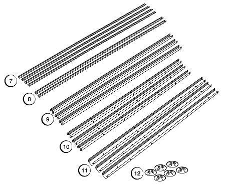
15 Page 14
16 Step 1 & 2 Page 15
17 Step 3 & 4 Page 16
18 Step 5 & 6 Page 17
19 Fitting the tubes When the frame has been assembled and fitted to the roof the tubes can then be fitted to the manifold. It is recommended to fill the system before fitting the tubes the tubes fit into a dry pocket so can be fitted after the system is filled. Filling the system prior to fitting the tubes will prevent the collectors from generating heat when trying to commission the system. See section 20 Page 18
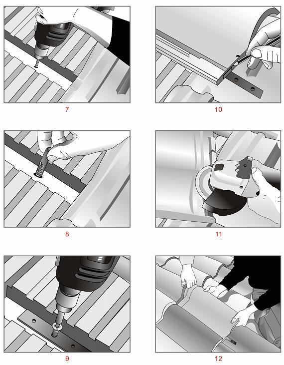
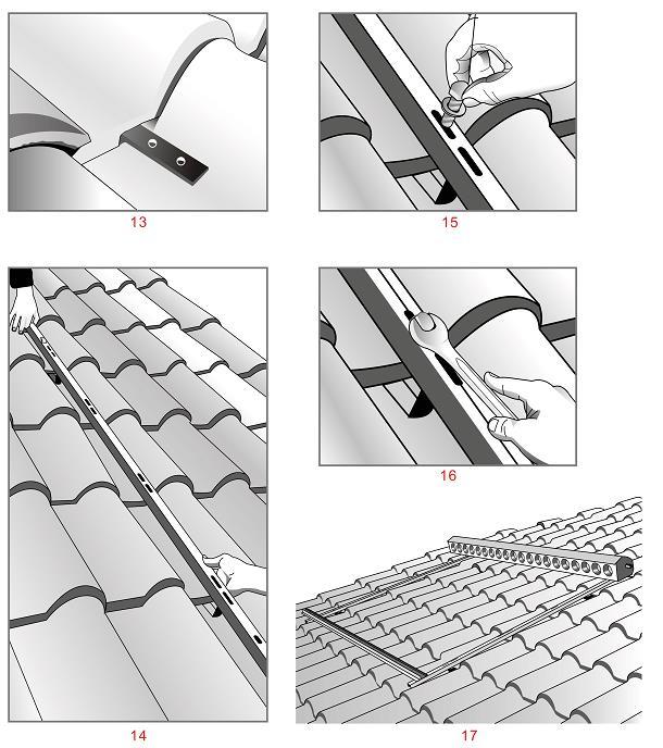
20 9.2 SLOPING ROOF Depending on the roof finish this will determine the correct roof fixing. The frame that holds the manifold and tubes is assembled the same it is the method of securing this frame to the roof that differs. Below shows how the frame would secure to a pitched tiled/slate roof and to a metal standing seam roof. Assembling frame 1 Manifold 2 Roof Strap (may not be required on metal roof) 3 Front Track 4 Bottom Track 5 Foot Holder 6 Tube 7 Bolt & Nut Lock Assembly Page 19
21 Page 20

22 ON ROOF TILE / SLATE KIT Page 21
23 Page 22
24 Page 23

25 ON ROOF METAL The frame is built in exactly the same way as before, however now the roof straps are not required and the frame should be fitted directly to the roof, this is done by fixing channels of unistrut to the roof via a standing seam clamp and then clamping the frame to the unistrut see below image.. Page 24
26 Fitting the tubes When the frame has been assembled and fitted to the roof the tubes can then be fitted to the manifold. It is recommended to fill the system before fitting the tubes the tubes fit into a dry pocket so can be fitted after the system is filled. Filling the system prior to fitting the tubes will prevent the collectors from generating heat when trying to commission the system. See section 20 Page 25

27 10 CONNECTING THE COLLECTORS It is recommended to fill the system before fitting the tubes the tubes fit into a dry pocket so can be fitted after the system is filled. Filling the system prior to fitting the tubes will prevent the collectors from generating heat when trying to commission the system. See section ARRAYS AND BANKS The complete installation of the solar collectors is called the solar array, the solar array may comprise separate groups of collectors, and these groups of collectors are called collector banks. A mix of LHP can be fitted to any one bank, however the total number of tubes in any one bank must not exceed 300 tubes. The flow must be balanced to each bank, the flow may also vary to each individual bank depending on the number of collectors fitted, and as such flow setters may need to be fitted as to regulate the individual flow rates. The maximum number of LHP TUBES in a single bank is CONNECTING FLOW AND RETURN The flow and return connections connected straight onto the manifold connections using the 2 22mm supplied fittings. Page 26


28 10.1 MULTIPLE MANIFOLD CONNECTION Multiple banks will have the flow and return connections connected to the manifold connections at each end of the bank, each manifold will then be joined together using a flexible 22mm straight coupling supplied with the collector. 22mm flexible coupling for joining collectors in a manifold. When installing multiple collectors spare connection sets and flow and return connectors may be left over. Page 27


29 10.1 FITTING THE COLLECTOR SENSOR The collector sensor should be fitted to the end collector on the array, this should be on the hot flow side of the array, if there are multiple banks then it should be fitted to the end collector of the array likely to receive the greatest solar energy. If the collectors have been installed on an east/west split or a similar type of split arrangement then 2 sensors should be fitted, one to the end collector in each relevant array. If using 2 sensors then please ensure a suitable solar controller is used that accommodates multiple sensors. The pocket for the sensor is located on the right hand side of the manifold see below image Apply heat transfer paste to the sensor before inserting into the sensor pocket this will ensure good thermal conductivity. Only use the sensor with the black cable, this cable is UV protected and can withstand the high temperatures associated with the collector. The sensor cable provided with the Lochinvar solar controller is around one meter long; this will need to be extended to reach the solar controller in the plant room. To extend the cable then a 2 core shielded cable (0.75mm²) should be used. It is advisable to use a 4 core cable, this way if any issues occur with one of the cores supplying the sensor it will be easy to change onto one of the spare cores. Page 28
30 11 STAGNATION Stagnation occurs when the solar storage vessel has reached its set point yet the collectors are still gaining energy from the sun. Stagnation refers to the fact that the solar pump has turned off meaning that the heat transfer fluid (glycol) is now stagnant in the pipe work. Short periods of stagnation are completely acceptable, however longer periods of stagnation can cause problems as follows; If the collectors reach lockout temperature 130⁰C (factory setting on the controller) due to the above, then the solar controller will lock out and not return to normal until the collectors cool down. If the solar storage vessel was to then cool down the available energy wouldn t be transferred from the collectors as the system is locked out meaning any solar gains would be lost. The glycol may lose its antifreeze properties, meaning adequate freezing protection is lost. Inhibitors designed to protect the pipe work begin to degrade and the glycol can become slightly acidic this can result in pipe work damage. In extreme circumstances the glycol can break down into a syrup like substance blocking the collectors and associated pipe work. This may result in collector damage and major repair work. Preventing prolonged stagnation; Don t oversize the system by having too many collectors Ensure the correct size storage vessel is selected see section 15 Ensure the correct flow rate is set for the arrays see section 13.2 Prolonged periods of system stagnation can still occur even with good system design. The amount of solar energy available to the system can be affected if the collectors lock out by exceeding their maximum working temperature. Using a collector cooling system as shown in section 12 can prevent systems from exceeding their maximum working temperature.. 12 COLLECTOR COOLING SYSTEM A collector cooling system works by allowing the collectors to dissipate their heat even when the solar storage vessel has reached set point. If the solar storage vessel reaches set point then the solar controller monitors the collector temperature, if the collector temperature during stagnation starts to rise and reaches 100⁰C (still below the maximum lockout temperature) then the solar pump is switched back on except this time a 3 way diverter valve is opened and diverts the glycol away from the solar storage vessel (apart from option 1 below) and passes to another place that the heat can be utilised or dumped to atmosphere. When the collectors have cooled back down to 90⁰C then the pump is turned off. If at any time the solar storage vessel calls for heat again then the 3 port valve is switched again and all the energy is transferred back to the vessel. 2 options are shown below for cooling the collectors using this method. 1. Divert the heat to a large thermal mass such as a swimming pool system or an area of ground utilised by a ground source heat pump. As above the excess heat would be transferred to the thermal mass thus keeping the collectors below the maximum lockout temperature and also protecting the glycol from damage. 2. By using a cooling fan, the cooling fan comprises of a finned heat exchanger that has a fan blowing across it as the hot glycol passes through the heat exchanger the heat is lost through the heat exchanger as the air passes over it very similar to how a car radiator works COLLECTOR COOLING SCHEMATICS Lochinvar limited may provide technical advice and guidance to assist with best practice, optimisation and installation of Lochinvar products; however, we will not be liable for any duties as designers under construction (design and management regulations 2015). In all cases where information is provided, the customer must assess and manage risks associated with the technical information and advice provided. Page 29
31 COOLING FAN LOCATED NEAR PLANT ROOM The above cooling system works as per the description found in section 12, note the 3 port valve; this will divert the glycol away from the coil and pass through the cooling fan until the collectors drop down to 90⁰C. If at any point the pre-heat vessel calls again for heat then the valve will again change position and normal flow to the coil will continue. The 3 port valve is energised via the solar controller the 3 port valve will have a switched output that can be used to energise a relay to switch on the cooling fan. NOTE the cooling fan will require its own power supply. Page 30

32 COOLING FAN LOCATED ON ROOF FAR FROM PLANT ROOM The above cooling system works as per the description found in section 12; the main difference with this layout is that the collector cooling fan is a great distance away from the plant room. To prevent having to run a long leg of pipe work from the outlet of the cooling fan to the negative side of the pump on the pump station, two 3 port valves are used; One on the roof to bypass to the cooling fan One in the plant room to bypass the coil The working principle is the same with the 3 ports valves diverting flow to the cooling fan and bypassing the pre-heat coil until the collector temperatures cool, again if at any time the pre-heat vessel calls for heat normal flow will start and heat the vessel. 13 PIPE WORK The 3 port valve is energised via the solar controller the 3 port valve will have a switched output that can be used to energise a relay to switch on the cooling fan. NOTE the cooling fan will require its own power supply. Page 31
33 13.1 PIPE SIZING When selecting the correct pipe work size it is important to have the following information; Required flow rate of the heat medium (Glycol) Head available from the pump Total pipe work distance including number and type of fittings 13.2 FLOW RATE The flow rate when using the LHP collector is calculated as follows For optimum performance of the collector we recommend a flow rate of 1ltrs/minute per 10 tubes, when the pump speed is at 100%. The solar controller will modulate the pump speed down as the temperature difference between the collectors and the storage vessel becomes less. Example Setting; 2 x LHP 30 collectors = 2x 30 tubes = 60 tubes total = 6ltrs/min flow rate when the pump is at 100% speed setting BALANCING THE FLOW When installing the collector banks it is important to have the correct flow going to each bank see section Banks may have a different amount of collectors per bank meaning different flow rates to each bank. To correctly balance the flow then it is recommended to fit solar approved flow setters on the flow side of the pipe work feeding each bank. To set the flow open all of the flow setters fully and set the main flow using the flow setter on the pump station see section When the combined flow has been set next adjust the flow to each bank by adjusting the individual flow setters. On systems with equal collectors in the banks, it is possible to balance the flow to the individual banks by balancing the pipe work on a reverse flow or return (tichelmann principle). The flow rate would then be set as per section PIPE WORK DISTANCE Measure the total distance of the pipe work in your solar loop, count the number of elbows and other fittings that will be installed on the loop. You will need this information to calculate your pipe work pressure drop. Page 32

34 13.5 PUMP HEAD This is the head available following the pressure drop across the solar array and the coil or plate heat exchanger feeding the pre-heat vessel. The pressure drop from your collectors and pre-heat vessel will be available from the supplier. When you know the system head loss, excluding the pipe work, look at the pump curve at the required flow rate and this will give you the head available from the pump. Now deduct the system head loss and this will show you what you have available for your pipe work/fittings. Pressure drops for pipe lengths/fittings can be found in documents such as the institute of plumbing design guide select a pipe size and calculate the pressure drop per metre, make sure that this combined pressure drop can be met by the available head from the pump. If using a Lochinvar solar package and assuming the total pipe work length is no more than 100 metres (50 metres each way) then the following can be used as a guideline. Number of LHP Tubes Up to 80 tubes Up to 240 tubes Up to 300 tubes Pipe size 15mm 22mm 28mm TABLE INDICATING TYPICAL SMOOTH COPPER PIPE WORK SIZE DEPENDENT ON COLLECTOR QUANTITY Solar approved automatic air-vents should be used on all high sections of pipe work to prevent airlocks when filling the system. The automatic air-vents should be isolated by using a check valve fitted beneath the air vent when the system has been filled - if the vent is left open it can result in a loss of fluid as vapour when the system goes into stagnation PIPE MATERIALS Only the following types of pipe are permitted on solar thermal installations Copper Stainless steel Mild steel continuous flexible stainless pipe, this is a corrugated type of pipe and is useful on small systems using short runs this type of pipe work comes pre-insulated and has a 2 core cable running its entire length that can be used for connecting the solar collector sensor. Flexible stainless steel pipe Due to the high pressure drop of this type of pipe work, systems with long pipe runs and high flow rates should not use flexible stainless steel pipe. Page 33
35 13.7 PIPE JOINTING METHODS Due to potential high stagnation temperatures and the chemical properties of glycol, only the following pipe jointing methods are permitted Brazed Solar Press Fit ( press fit with solar rated EPDM O-Rings) Compression If using jointing compounds please ensure these are solar rated. The following jointing methods must not be used Solder PEX Plastic PEX-ALU-PEX Galvanised pipe or fittings Page 34
36 13.8 EXPANSION VESSEL SIZING Every solar thermal system will have a solar expansion vessel included within the equipment supplied. This has been based on an average system and as such as part of the installation/commissioning procedure the size must be checked to ensure the vessel is large enough and if required swapped for a larger vessel. Failure to check and install a correctly sized expansion vessel will lead to overheating problems and premature component failure that will not be covered under the manufactures warranty In order to accurately size a solar expansion vessel we need to use the following formulae: V N =((V e + V v + V d ) x (P max +1)) /(P max -P prec ) Where VN =nominal expansion vessel volume Ve =expansion volume of the solar fluid (expansion coefficient (0.09) x system volume) Vv =amount of fluid in the expansion vessel in litres (0.02 x system volume) minimum must be 3 litres Vd=volume of steam in litres (1.1 x system volume) Pmax= maximum working pressure of the system in bar Pprec= pre-charge pressure of the expansion vessel EXAMPLE SIZING Solar collector volume=60 litres Solar pipe work and other components = 105 litres Glycol 42% Maximum working temperature of the system 130 C Safety valve setting 6 bar Minimum working pressure 0.7 bar Static head on the system 20 metre Ve = 0.09 x =14.85 Vv = 0.02 x =3.3 litres( minimum must be 3 litres) Vd= 1.1 x =93.4 Pmax= 0.9 x 6 =5.4bar Pprec = =2.7 bar V N =(( ) x (5.4+1)) /( )= V N = x (6.4 / 2.7) = V N = x 2.37 = V N = litres The nearest equivalent or larger sized commercially available vessel should be chosen The sizing of the solar expansion vessel is for guidance only, sizing should be checked and verified by a competent engineer Page 35
37 13.9 PIPE INSULATION Pipe insulation in a solar thermal installation is very important; the heat energy gained by the collectors needs to be transferred to the vessel with minimum heat losses. When selecting insulation for the solar pipe work the following should be considered; Sufficient insulation thickness (see table) No gaps ensure fittings, vessels and connections are also insulated) Insulation type is suitable external pipe work should be UV protected, be suitable for all weather conditions and have a level of protection from birds and animals. The insulation should be suitable for high temperature use PIPE SIZE mm INSULATION THICKNESS mm Up to Up to >42 Equal to the nominal width of the pipe TABLE SHOWING MINIMUM INSULATION THICKNESS Do not insulate the section of pipe work between the solar expansion vessel and the system, this will allow heat to be dissipated from the glycol whilst expanding into the expansion vessel; this will increase the life expectancy of the expansion vessel. Page 36


38 14 SYSTEM COMPONENTS In order for a solar thermal system to operate correctly and efficiently, certain key components are required. Component type and quantity will vary on each individual system design; however the following components are commonly used; Solar controller Pump station Alarm module Flow sensor Solar expansion vessel Intermediate Vessel Heat meter Collection vessel Heat transfer fluid Storage vessel - this may be a single or twin coil indirect vessel or a thermal store Page 37
39 14.1 SOLAR CONTROLLER The solar controller is the brains of the system, monitoring temperatures and system problems. The controller runs the solar pump station along with various other system components SOLAR PUMP STATION A solar pump station transports the solar fluid (Glycol) through the solar system. The solar controller powers the pump station depending on the settings made within the controller ALARM MODULE The AM1 alarm module connects directly to the solar controller. The alarm module has a volt free contact that will close in the event of a system fault. The module also flashes red NOTE under normal operation the module is illuminated red and only flashes red on fault FLOW SENSOR The solar controller uses the flow sensor to monitor the flow of glycol within the solar circuit. In the event of a noflow situation, for example a pump failure, the controller will display a fault and close the contact on the AM1 module SOLAR EXPANSION VESSEL An expansion vessel absorbs the expansion volume of the solar fluid within the solar system as it heats keeping the system at a semi constant pressure. These expansion vessels are factory set with a cushion pressure of 3bar (this pressure can be adjusted) and are available in five different sizes (24, 35, 50, 80 and 100 litres). See section 13.8 expansion vessel sizing INTERMEDIATE VESSEL An intermediate vessel sits above the solar expansion vessel see below drawing. Evacuated tube systems can experience high glycol temperatures. The intermediate vessel is basically a hollow vessel that holds a volume of glycol acting as a heat sync cooling down the glycol within the intermediate vessel. It is this cooler glycol that will be pushed into the solar expansion vessel during expansion thus protecting the diaphragm on the solar expansion vessel. Page 38
40 14.7 HEAT METER In order to claim the Renewable Heat Incentive (RHI) for eligible installations, a suitable heat meter is required. The HM1.5 is an MID Class 2 RHI compliant heat meter suitable for solar thermal systems. The heat meter is mains powered and comes complete with a volt free contact, which closes each time the system generates 1 kwh of energy. The heat meter also has a MBUS connection. The heat meter is calibrated on supply depending on the Glycol type used. The meter measures the temperature difference across the flow and return pipe work, along with the flow rate within the system. With this information, the heat meter calculates the energy transferred to the water and displays this in kwh COLLECTION VESSEL If an over pressure situation occurs, such as a failure of the expansion vessel the pump station has a 6 bar pressure relief valve that will discharge the excess pressure. Rather than discharging Glycol onto the plant room floor or down a drain point, we collect the discharged glycol in a container for re-use. The container should be large enough to hold the full contents of the solar thermal collectors HEAT TRANSFER FLUID (GLYCOL) Glycol is the solar fluid that circulates around the solar thermal system and transfers heat energy from the collectors to the storage vessel. This Glycol is a 40% mixed solution, is corrosion inhibited and has an anti-frost agent. Lochinvar only recommend the following glycol; HGLHTF - High Grade Lochinvar Heat Transfer Fluid THESOL 20ltr tubs To maintain the warranty on the collectors it is important that any future glycol replacement uses THESOL glycol (available from Lochinvar limited). Page 39
41 Technical data sheet for Lochinvar Heat Transfer Fluid - THESOL To maintain the warranty on the collectors it is important that any future glycol replacement uses THESOL glycol (available from Lochinvar limited). Page 40

42 15 STORAGE VESSEL The energy collected by the solar collectors is used to heat the cold water supply that feeds your primary heat source, such as a direct fired water heater. Sizing the storage vessel correctly is important to ensure that the solar thermal system operates efficiently for as long as possible to take advantage of the almost free limitless energy. Storage vessels are sized on both the storage volume and coil size STORAGE VOLUME The vessel should be sufficiently sized to store the energy from the collectors, it is recommended to have 50ltrs of storage per m² of collector (active area). For sites such as a hotel when the main peak demand may be in the evening, it is recommended to have even higher storage so as to capture as much free energy during the day as possible. Sites with higher demand throughout the day may have smaller storage as the pre-heat may never reach set point anyway. Number of tubes Active Surface area Storage for High Demand System (litres) Storage for Low Demand System (litres) TABLE SHOWING TYPICAL EXAMPLES OF MINIMUM AND MAXIMUM STORAGE VESSELS DEPENDENT ON SYSTEM DEMAND 15.2 COIL SIZE SINGLE COIL VESSEL In order for the system to operate efficiently and without problems, the vessel must have a coil sized at 0.2m² of coil surface area for every m² of collector absorber area. Example calculation (5 LHP30 Evacuated tube collectors on a Low demand system) see above LHP30 Absorber area 2.8m 2 Recommended minimum coil surface area for 5 x LHP30+ = 5 x 2.8m² = total absorber area 14m² 0.2 x 14 = 2.8 = minimum coil surface area of 2.8m² Minimum storage vessel size required = 5 x LHP30 = 150 tubes (see table above) =700Litres Most standard hot water vessels will not have a coil large enough to operate correctly on a solar thermal system. Only use vessels specially designed with oversized coils. Do not use a vessel with an undersized coil; this will result in overheating of the solar thermal array, this could cause safety devices to operate and/or damage the glycol within the system TWIN COIL VESSELS The lower coil is used to heat the cold feed on a twin coil vessel, the upper coil is heated by the primary heat source to provide the domestic hot water at the correct temperature. When selecting a twin coil vessel attention needs to be made to the upper and lower volumes fed by the coils for example a 1000ltr twin coil will have typically 400ltrs available for your solar volume and 600ltrs available for your domestic hot water. The volume and coil sizes shown in sections 15.1 and 15.2 still need to be adhered to. If the coil size on a single coil vessel for the required volume isn t adequate it may be possible to use a twin coil vessel and connect the two coils in series, this way you may achieve a greater coil surface area. Page 41
43 15.4 THERMAL STORE A thermal store is able to combine multiple heat sources for the generation of hot water. When used with a solar system it is typically only connected to the solar circuit. The thermal store comprises of a store of water that is heated by the solar collectors via an indirect coil, the water that is heated stays within the vessel as a thermal store. A large stainless steel domestic hot water coil is submerged within this thermal store and as cold water passes through this coil, heat energy is transferred indirectly from the thermal store to the cold water. Due to the fact the water inside the thermal store is separate from the domestic hot water there is a much lower legionella risk, thus a pasteurisation (see section 18) may not be required. When connecting to the solar circuit sections 15.1 and 15.2 should still be adhered to, dependent on how many coils are being utilised by the solar circuit. A risk assessment should be carried out on any installation to ascertain the individual legionella risk DIRECT VESSEL Systems that have a large number of collectors may not have a suitable indirect vessel available due to the coil size. This may mean having multiple indirect vessels to increase the coil surface area available. An alternative is to use a direct vessel with a plate heat exchanger see schematic The plate heat exchanger should be sized so its capacity matches that of the solar array in terms of power. The power of the array will vary depending on each installation, however if the following calculation is done this will assist in sizing the capacity of the plate. The average solar radiation in the UK is 1000W/m² - the LHP20 has an active absorber area of 1.9m² and the LHP30 a surface area of 2.8m² meaning the potential solar radiation hitting the absorber would be 1000W/m² x 1.9 = 1900W or 1.9kW per LHP20 and 1000W/m² x 2.8 = 2800W or 2.8kW per LHP30. Due to the efficiency of the collector this will then be reduced the efficiency of the LHP20 and LHP30 is 59% meaning the LHP20 could potentially receive 1900W x 0.59 = 1121W or 1.1kW per LHP20 collector. The LHP30 could potentially receive 2800W x 0.59 = 1652W or 1.6kW per LHP30 collector. Example a 150 collector system would require a plate heat exchanger with a power capacity of 150 tubes (5xLHP30) x 1.6kW (potential power of the collector) = 5x 1.6kW = 8kW (power of the plate heat exchanger). Other considerations when sizing the plate heat exchanger would be; The flow rate on the primary side of the plate (the solar circuit side) Flow/Return temperatures on the primary side (the solar circuit side) of the plate, it s best to use poor performing temperatures when sizing the plate for example 50/30⁰C The flow rate on the secondary side (this will normally be the same as the primary but would be supplied by the plate manufacturer) Flow/Return temperatures on the secondary side of the plate, it s best to use poor performing temperatures when sizing the plate for example 25/45⁰C The medium used on the primary/secondary side, for example glycol on the primary and water on the secondary. Suitable pumps are selected for both the primary and secondary sides taking into account the flow rates and pressure drops. Using the above information a suitable plate should then be able to be sized and selected from a plate manufacturer. Page 42
44 16 SCHEMATICS Solar thermal systems tend to be bespoke in design; as such it is difficult to show schematics to cover every design. The schematics shown in sections 16.1, 16.2, 16.3, 16.4 are generic but typically all designs follow this principle. Lochinvar limited may provide technical advice and guidance to assist with best practice, optimisation and installation of Lochinvar products; however, we will not be liable for any duties as designers under construction (design and management regulations 2015). In all cases where information is provided, the customer must assess and manage risks associated with the technical information and advice provided. Page 43
45 16.1 PRE-HEAT SYSTEM USING SINGLE COIL VESSEL This is the most common type of solar pre-heat system. The solar collectors heat a pre-heat vessel which then feeds the primary water heater, such as a direct fired storage water heater. The vessel would be correctly sized in accordance with section 15. Due to the fact the pre-heat vessel may at times not fully reach 60ºC the vessel will need to be pasteurised as per section 18 SINGLE COIL PRE-HEAT SYSTEM Page 44
46 16.2 PRE-HEAT SYSTEM USING TWIN COIL VESSEL This section is similar to the single coil system; the difference being that instead of the pre-heat then feeding a separate water heater or indirect vessel, the upper coil is the primary heat source providing the DHW, the cold feed is simply pre-heated in the lower section of the vessel via the solar coil. The vessel should be sized in accordance to section 15. To pasteurise this type of vessel a pump should be fitted to the vessel to comply with section 18. TWIN COIL PRE-HEAT SYSTEM Page 45
47 16.3 PRE-HEAT SYSTEM USING PLATE HEAT EXCHANGER If a selected vessel doesn t have an adequate coil size as per section 15 then a plate heat exchanger should be sized and selected, this would then be connected to a direct storage vessel that would be heated via the plate. The pre-heat vessel will need to be pasteurised as per section 18. PRE-HEAT SYSTEM USING A PLATE HEAT EXCHANGER Page 46
48 16.4 PRE-HEAT SYSTEM USING THERMAL STORE A thermal store incorporates two internal coils and multiple connections. The main body of water within the HSV is heated via the indirect coil(s) and acts as the heat transfer to the high recovery stainless steel DHW coil which can be used to provide a pre-heated cold feed to a primary heat source. Due to the low volume of potable water within the DHW coil and when used under normal operating conditions the build up of legionella bacteria is greatly reduced, meaning that a pasteurisation regime is not usually required however a risk assessment should be made on each individual project to ascertain if such a regime is required. Details on sizing a thermal store can be found in section 15.4 PRE-HEAT SYSTEM USING THERMAL STORE Page 47

49 17 WIRING 17.1 SOLAR CONTROLLER (LPC) The control of the system is provided by the solar controller; all other system components connect back to this unit. The controller has 4 individual relay outputs with a maximum 1A draw from each relay. These relays can be used to operate valves and pumps. There is also a permanent live output from the controller which can be used to power items such as the heat meter or a solar display, the maximum current draw from this output is shown on the below table. LPC SOLAR CONTROLLER Power Supply VAC ( Hz) Internal Fuse 4A Power Consumption Standby <1W Total Switching Capacity 4A 240VAC Relay 1 to 3 Type Semiconductor relay 1A max each Relay 4 Electromechanical relay 1A max VBUS Current Supply 35 ma Always disconnect the controller from the power supply before opening the housing. A separate manual is available for the solar controller which gives further installation details. To access the wiring terminals on the solar controller make sure power is off to the unit and then remove the small screw in the centre of the controller, this will then give access to the terminals on the controller. SOLAR CONTROLLER Page 48
50 17.2 PUMP The pump is located within the solar pump station. All the pumps supplied by Lochinvar are of the high efficiency type with PWM control. The pump can be wired directly to the solar controller, the controller will provide the pump with a power supply and the control will be performed by the PWM connection. For full details on wiring the pump see section 17. For systems using multiple pumps on the same controller it may be required to fit a separate permanent power supply for the pumps and only wire the PWM controls back to the controller. SINGLE PUMP CONNECTED TO SOLAR CONTROLLER TWO PUMPS CONNECTED TO SOLAR CONTROLLER WITH SEPARATE POWER SUPPLY Page 49
51 17.3 HIGH LIMIT CONTROL Solar thermal pre-heat systems must comply with regulations in terms of temperature control, Lochinvar recommends the use of a 2 port motorised valve connected via a high limit stat. The power supply that opens the 2 port valve is wired in series with the high limit stat, in the event that the stat detects a temperature above 82 C then the power supply to the 2 port valve is cut, this will close the valve and stop any further flow of energy into the vessel via the indirect coil. The solar thermal system has a flow sensor connected to the primary flow which will then detect a no-flow situation and alarm the system. When the cause of the over-heat has been found then the high limit stat can be reset allowing the 2 port valve to again open and normal flow on the primary circuit to resume OTHER ANCILLARIES 2 PORT VALVE CONNECTED IN SERIES WITH HIGH LIMIT STAT The system may have solar Ancillary components these can be connected to and controlled by the solar controller; some items can take their power supply from the controller depending upon the Amps required. Always check with the solar control ICM instructions before connecting any ancillary equipment. The wiring diagram below shows connection for common system components, this wiring diagram may slightly differ depending on any particular system design. This is a list of the common system components that connect to the solar controller. Pump station details shown in 17.2, can be controlled by the solar controller AM1 alarm module - details shown in 14.3, connected to the VBUS connection to the controller Heat meter details shown in 14.7 the heat meter requires a power supply, this can be taken from the solar controller. Flow sensor details shown in 14.4 the flow sensor connects to VFS or RPS depending on the type of flow sensor used. Pasteurisation pump details shown in section 18 the pump may be controlled by the solar controller Sensors the collector and vessel sensors connect directly to the solar controller. Various other components can be connected to the solar controller; this is all dependent on the individual design. For further details on this refer to the relevant manual for the system component or the separate manual for the solar controller. Page 50
52 17.5 WIRING DIAGRAM The below wiring diagram only covers the LPC controller supplied by Lochinvar Limited other controllers may be used please refer to the relevant manual. FOR FURTHER DETAIL PLEASE REFER TO THE INDIVIDUAL COMPONENT MANUALS. TYPICAL WIRING DIAGRAM LAYOUT Page 51
53 18 PASTEURISATION Legionella bacteria are commonly found in water. The bacteria multiply where temperatures are between C and nutrients are available. The bacteria are dormant below 20 C and do not survive above 60 C. Legionella legislation requires any hot water storage vessel to raise the temperature of the stored water to 60 C for at least 60 minutes every day. Due to the intermittent energy input from solar thermal there may be days when this is not achieved, during winter months this period could be extended. Solar pre-heat systems must comply with the ACOP and guidance on regulations covering L8 and HSG274 part 2 - Legionella control in water systems. One method of control is thermal disinfection; this is achieved by lifting the pre-heat vessel to 60ºC and holding this temperature for one hour. The solar controller can be programmed to run a thermal disinfection if required, it will do this by monitoring the pre-heat vessel, if the vessel fails to achieve 60ºC during its monitoring period it will use one of the below methods to lift the vessel temperature to 60ºC for one hour. The time this is done can also be programmed. The thermal disinfection should be programmed to run at a time that will not affect any potential solar thermal gains into the storage vessel. This will be site dependent but with careful planning the potential loss of solar gains can be minimised. Thermal disinfection can be achieved in one of the following ways, these can either be controlled by the BMS or the solar controller itself Details on programming the solar controller can be found in the separate manual for the controller PASTEURISATION PUMP The pre-heat vessel can be heated by the primary heat source such as a storage water heater or boiler with indirect vessel, the hot DHW flow from the primary heat source will have a section of pipe work that feeds to the cold feed of the pre-heat vessel. When this pump is energised it will circulate the water from the pre-heat vessel to the primary heat source until the pre-heat vessel is heated to 60ºC PASTEURISATION METHODS Page 52
54 18.2 IMMERSION HEATER An immersion heater can be fitted to the pre-heat vessel and be powered to come on at a given time to lift the vessel to 60ºC. IMMERSION HEATER AND DE-STRATIFICATION PUMP USED FOR PASTEURISATION If the immersion heater is powered by the solar controller then this must be done via a separate volt free relay powered by the controller due to the high current draw from the immersion heater. It may be advisable to also fit a de-stratification pump to the vessel to ensure the complete contents of the vessel are heated to 60ºC and not just the volume of water above the immersion heater, this pump could be energised to come on at the same time as the immersion heater DE-STRATIFICATION PUMP When using a twin coil vessel, normally the primary heat source is used to heat the upper coil thus maintaining the top section of the vessel to 60ºC. A pump can be fitted to the pre-heat vessel to circulate the contents of the vessel so the top coil can heat the complete vessel to the required 60ºC THERMAL STORES Thermal stores such as the HSV range available from Lochinvar generally do not require a pasteurisation regime as they do not store domestic hot water but utilise a pre-heat coil to heat the cold water as it flows through the pre-heat coil. The use of a HSV thermal store will reduce the energy impact of pasteurising the pre-heat store daily which can during winter months negate any energy savings from the solar thermal system. Further details of the HSV thermal store can be found at Any solution used must comply with the requirements of part G of the building regulations and a thorough risk assessment undertaken as required under legionella legislation. Page 53
55 19 FINAL CHECKS PRIOR TO COMMISSIONING Ensure that no more than 300 tubes are connected in any single bank Make sure the relevant roof fixing kit is correct, if using A-Frame ballast ensure correct ballast has been used. Make sure the flow return connections to each bank of collectors are correct and that the pipe work is balanced or flow setters have been used The solar sensor is installed in the pocket below the top right hand connection only a single sensor is required for the complete array, unless a split system is being used such as an east/west split. It is recommended to fill the system before fitting the tubes the tubes fit into a dry pocket so can be fitted after the system is filled. Filling the system prior to fitting the tubes will prevent the collectors from generating heat when trying to commission the system. See section 20 Page 54
56 20 COMMISSIONING The following Commissioning regime must be followed along with the record sheet in section 22.This is a requirement under the solar thermal collector warranty. This should only be completed by a suitably competent person. Commissioning should be carried out by a suitably competent engineer. COLLECTORS MUST BE COVERED THE DAY BEFORE COMMISSIONING Before starting check the collector temperature on the solar control, if this is higher than 30 C then commissioning cannot take place. Prior to commissioning the following checks should be made All pipe work and wiring connections are correct The collectors are sufficiently cool prior to filling Pipe Work has been pressure tested if not then start at section 20.1 if pipe work has been pressure tested and a certificate is available to show this then start at section PRESSURE TESTING PIPE WORK Prior to filling the system it is advisable to check the integrity of the hydraulic circuit by pressure testing the pipe work. To pressure test the hydraulic circuit, the circuit will need to be filled and held under pressure for a period of time, this time can be site specific but is typically for around 2 hours. To fill the circuit follow the instructions given in the relevant pump station manual with your system. The system may be filled and pressure tested with either; GLYCOL (Only use glycol supplied by Lochinvar see section 14.9) this is the preferred method. Air using compressed air and leak detect spray air testing is more hazardous than using glycol, as such this manual doesn t cover this process and if this is the chosen method then the correct procedure in terms of safe working should be followed. DO NOT USE WATER TO PRESSURE TEST THE PIPE WORK It may not be possible to fully empty the contents of the collectors following a pressure test. If pressure testing during sub-zero temperatures it is advised to do this with GLYCOL, otherwise irreparable damage may occur to the collectors. To pressure test the system with glycol then the following or a similar method should be followed and a test certificate signed and kept as a record this has been done. Please ensure any pressure gauges used are calibrated and have been serviced. 1. Start to fill the hydraulic circuit refer to the relevant solar pump station manual for details on filling the system. Whilst filling it is advisable to walk the route to look for any obvious leaks. If caught early this may be heard as air leaking from the circuit. 2. Release air from all high sections in the pipe work, to ensure the complete circuit is full and there are no air locks. The use of solar approved Automatic Air-Vents should be used on all high points. 3. Once the system is full then raise the pressure into the system, this pressure varies depending on site but typically the pressure should be set to 3 bar and held for 2 hours if the pressure gauge still reads 3 bar after the given time period then the test has passed if there has been a significant drop in pressure then the leak will need to be detected and the test repeated. 4. When the test has been completed this should be witnessed and a test certificate signed and kept as a record of the test. 5. Drain the system by relieving the pressure the air vents at the highest points may again need to be opened to allow air back into the system and allow the glycol to drain off. Page 55

57 The pressure relief valve on the solar pump station is factory set to 6 bar if this is exceeded during the pressure test then the valve will discharge and may release hot liquid into the area. If site requirements require a pressure test at higher pressures, the solar thermal collectors should be isolated before any high pressure testing is carried out to prevent damage which would not be covered under the collector warranty SETTING THE SOLAR EXPANSION VESSEL CUSHION PRESSURE The cushion pressure on the expansion vessel should be set to 0.2 bar less than the cold fill pressure; typically the fill pressure will be 2bar, as such set the cushion pressure on the expansion vessel to 1.8 bar FILLING THE HYDRAULIC CIRCUIT The system is filled via the solar pump station for connection details please refer to the separate manual for your particular pump station. Please make sure the pipe work is fully flushed of any potential debris prior to filling. Filling the circuit is similar to the procedure when pressures testing the pipe work; however it is now important to make sure that all the air bubbles are removed from the circuit (even micro air bubbles) this can only be achieved by circulating the Glycol mix around the hydraulic circuit using a filling station. TYPICAL FILLING STATION TYPICAL PUMP STATION 1. Fill the filling station with Glycol have further glycol available to top up. 2. Connect the filing station to the solar pump station, the flow from the filling station should connect to point (C) and the return to the filling station should connect to point (D) full details of connection can be found in the separate pump station manual depending on the model used. 3. Close the isolating valve (B) located just above the flow setter (A) on the pump station; this will prevent glycol re-circulating just around the filling station. 4. Open the fill (C) and return valve (D), in the beginning only slightly open valve (D) on the pump station 5. Switch on the solar filling station, glycol will now be pumped into the solar loop and air will be seen pushing into the glycol stored in the filling station. Keep an eye on the level of glycol in the filling station and fill as necessary. Page 56

58 Any air vents on the pipe work may need to be open during the filling stage to allow the removal of any air-locks. Ensure these are then closed when the loop is full. 6. Continue circulating the glycol around the circuit adding more glycol into the filling station and the level stops dropping indicating the loop is full. Continue circulating for a period of time until no more air bubbles are seen in the filling station. To assist with air removal from the circuit, try stopping and starting the filling station, the sudden changes in fluid motion can dislodge trapped air bubbles. Occasionally open the isolation valve on the flow meter to make sure no air is trapped in the sight glass. 7. When satisfied all the air is removed from the solar loop, isolate the return valve (D) and fully open the isolation valve (B) just above the flow setter (A), continue pumping into the solar loop this will cause the pressure in the loop to rise, continue to do this until the required pressure is set. This must be set to 2 bar minimum but may be higher depending upon site requirements. 8. When the pressure has been set switch off the filling station and isolate the fill loop connection (C). 9. Check the circuit for leaks and monitor the system pressure for drops. 10. The above procedure may need to be repeated if all the air hasn t been removed or the pressure drops with no signs of any leak. 11. If the plumbing is sound and no leaks are found then disconnect the filling station and drain back into the glycol containers any unused glycol. Cap the fill (C) and return points (D) on the solar pump station. It is advisable to return and check the system 2 weeks after initial fill to ensure no air-locks have formed. If air-locks have formed then the above procedure should be repeated SETTING THE FLOW RATE Setting the correct flow rate depending on the size of the array is important to ensure that all the energy is removed from the collectors and delivered to the pre-heat vessel as efficiently as possible. See section 13.2 for recommended flow rates. Check the individual manual for your pump station, however; most pump stations set their flows by the following method. If the solar pump has speed settings, set the pump to the lowest speed. Switch the pump to manual via the solar controller see the individual manual for the solar controller for details on how to do this. Locate the adjusting screw (B) above the site glass and turn clockwise to decrease the flow. The flow rate will be shown on the site glass gauge (A), do this until the required flow is measured. If the required flow can t be met then change the pump speed up one level and try adjusting again. CLOSE UP VIEW OF FLOW SETTER Pump stations may have modulating PWM pumps for these pump stations the pump will find its own flow rate depending on the collector and vessel temperature. The pipe work still needs to be balanced as per section Page 57
59 20.5 CONTROLLER SETTINGS When the system has been filled and the flow set then the controller should next be programmed. Full details for programming the controller can be found in the individual manual for the LPC controller. Depending on the individual design of the system depends on the program that will be set on the controller, however, the key points to cover when programming the controller are as follows; Vessel set point The set point you would like to heat the pre-heat vessel to should be programmed the standard set point is 60⁰C but this can be adjusted to a higher temperature of 65⁰C. If the maximum energy from the collectors is to be stored then you could increase the set point to 80⁰C, however this is close to the high limit set point which is typically 82⁰C. If temperatures above 65⁰c are stored in the pre-heat vessel it will be necessary to fit a tempering valve to ensure high temperatures are not supplied at the outlets. Collector switch on set point This is the temperature difference that needs to exist between the pre-heat vessel and the collectors. Typically this would be set to 10K meaning the collectors will need to be 10K hotter than the pre-heat vessel for the solar pump to switch on. Collector switch off set point This is what the temperature difference needs to drop between the collectors and the pre-heat vessel to for the solar pump to turn off. We recommend this is set to 5K. Minimum collector switch on temperature A minimum collector temperature can be set that the collector needs to reach before the solar pump will switch on, independent to the collector switch on point. This is to prevent the solar pump activating if the collectors are sat at a low temperature but still 6⁰C above the pre-heat vessel. This is an optional setting however it is normally recommended to keep the system inactive unless the collectors reach a minimum temperature of around 25⁰C. Maximum collector temperature before lockout During times when the pre-heat vessel is at set point and the solar pump has turned off, the collectors will still be receiving energy and their temperature will increase, this is called stagnation. If the collectors reach a certain temperature the glycol may begin to boil and vapour will form, when this happens the solar pump should be prevented from activating (as the preheat vessel drops in temperature) to prevent the circulation of steam which will damage system components. The factory set point for this is 130⁰C. Flow sensor It is recommended to fit a flow sensor to the solar loop, Lochinvar supply a flow sensor with all their solar packages. When fitted the flow sensor connects to the solar controller and the controller needs to be programmed depending on the type of flow sensor fitted. Pasteurisation settings If the solar controller is used to run the pasteurisation cycle see section 18. The monitoring period, pasteurisation time and set points are all programmed into the controller. During the monitoring period, if the solar controller reads the pre-heat vessel has reached the minimum set point, say 60 ⁰C, and remained at that temperature for 1 hour during the monitoring period it will cancel the pasteurisation run for that particular day. Depending on the system design many other parameters can be set the above points are the main settings that need consideration on the majority of installations. On completion fill in the Commissioning sheet, see section 24 Page 58
60 20.6 DRAINING THE HYDRAULIC CIRCUIT CAUTION BURN RISK Before draining the hydraulic circuit please make sure the system is at a safe temperature to discharge the glycol to prevent the risk of burns. It is highly advisable to cover the collectors or perform maintenance first thing in the morning to prevent there being high temperatures or pressures in the solar primary circuit. To drain the hydraulic circuit of glycol complete the following Isolate the system electrically If possible cover the collectors Open any air valves ( only if the primary solar circuit is at a safe temperature and pressure) at the highest point on the system, this may be the air valve located on the top left of each collector bank. Locate drain valves at the lowest point of the system Open drain points and collect glycol in suitable containers See glycol disposal in section 22 To refill the circuit with Glycol following section MAINTENANCE Isolate any electrical supplies before carrying out any electrical work. The following maintenance regime must be followed to maintain an efficient operating system and is a requirement under the solar thermal collector warranty. This should only be completed by a suitably competent person. If the electrical supply to the system is to be switched off then do this at a time of low solar gain or cover the collectors, this is to prevent the collectors reaching their maximum temperature see maximum collector temperature in section MONTHLY The solar controller should be checked to ensure the system is operating correctly, from the display you can view the collector and vessel temperatures. If the system is in fault then an error code will be displayed. Check for weeps/leaks from pipe work Check the system pressure, the system pressure should be within +/- 0.5 bar from the initial fill pressure. If the system has a pressure outside of the normal ranges report this to a service engineer. If no flow sensor is fitted to the system then ensure adequate flow is present when the pump is running Check the condition of the solar pre-heat vessel. Visual inspection that there is no damage to collectors or fixings In addition to the above, every installation should have a specific anti-legionella regime in place and the details of this should be logged. Page 59
61 21.2 ANNUAL CARRIED OUT BY COMPETENT SERVICE ENGINEER Speak with the customer to establish if they are happy with their system and to discuss anything they may have noticed during their weekly checks. Speaking with the customer can save valuable time in determining the correct operation of the system. Check for damage to the absorber or glass along with the integrity of the mounting frame. If roof access isn t available then a visual inspection from the ground is normally suffice. Do not clean the collector glass, aggressive washing may cause damage to the surface of the collector and affect performance. If there is heavy debris such as bird droppings then this should be removed very carefully with warm water. Check the system pressure, the system pressure should be within +/- 0.5 bar from the initial fill pressure. If there is a major drop in the pressure, check for glycol in the discharge container. If no glycol is found in the discharge container then this may indicate a leak on the pipe work that needs to be located. If the pressure is higher than expected then follow the next step. Isolate the expansion vessel from the solar circuit and use a manometer to check the cushion pressure on the expansion vessel; this should be 0.2 bar less than the cold fill pressure of the solar circuit (this pressure should have been recorded on the initial commissioning sheet). Manually operate the pump and check that there is correct circulation in terms of flow rate around the solar circuit. See section If the flow rate can t be adjusted then check the integrity of the pump or for any blockages around in-line filters, items such as heat meters have in-line filters built into the unit. If everything is clear then the blockage may be down to degraded glycol. Drain off a small amount of glycol and place into a small container. Take a sample of this glycol and place it onto a refractometer, this will allow you to view the antifreeze level of the glycol. Check the data sheet for the glycol used and this will allow you to determine if the glycol is still protecting from freezing to a sufficient level. Now dip a ph test strip into the glycol, the target value for the glycol should be approx As glycol breaks down it becomes more acidic and this may cause damage to the pipe work and system components, as such if the ph level drops less than ph7 replace the glycol. See section 20.6 CAUTION BURN RISK If replacing the glycol please make sure the system is at a safe temperature to discharge the glycol to prevent the risk of burns. Run a visual inspection of the pre-heat vessel for signs of leaks or damage to its insulation. Check the vessel for scale formation and remove as necessary, also check the condition of any sacrificial anodes or that any impressed current system such as the Correx system is working correctly. Check the settings in the solar controller to ensure that they are set to provide optimal performance of the system. Following the conversation with the customer, as mentioned in the first step, you may find you wish to make certain setting adjustments. See section 20.5 and the individual manual for the solar controller for moiré detail. Page 60
62 22 DECOMMISSIONING Due to the pressure and potential temperatures found within a solar thermal system, decommissioning should only be conducted by a suitable competent engineer. CAUTION BURN RISK Cover the collectors or complete the works during a time of low solar gain such as early morning to reduce the possibility of high temperatures. The decommissioning of a system will be completed in 5 steps as follows; 22.1 ELECTRICAL ISOLATION Isolate the solar controller from the mains Remove all electrical connections to the controller from sensors, valves and other ancillary components such as the heat meter Remove all earth cables from pipe work 22.2 REMOVAL OF THE HEAT TRANSFER FLUID - GLYCOL Drain the system see section REMOVAL OF THE SOLAR PIPE WORK LOOP Remove all pipe work between collectors and pump station Remove all pipe work in the plant room Remove all system components connected to the solar loop such as the solar expansion vessel Disconnect pipe work to the solar pre-heat vessel Depending on the position of drain valves, fully removing all the glycol from the circuit is difficult, please note that when removing pipe work at the lowest levels of the circuit then glycol my still be present in the pipe work and fittings DISMANTLE AND REMOVAL OF THE COLLECTORS Remove the collectors and all related fixing frames. Remove any ballast that may have been used to support the frames Any roof penetrations should be made weather tight CAUTION BURN RISK The collectors may still be hot even if they have been drained of all their contents. Page 61

63 22.5 DISPOSAL All components such as the collectors, solar pump station and other solar ancillaries may be stored and used again. Glycol The glycol used in solar thermal systems is called propylene glycol; propylene glycol is non-volatile but is miscible with water. Propylene glycol is not subject to registration as a hazardous material according to EEC directives; the solution should be disposed of taking into consideration local environmental and health and safety legislation. Although glycol is not harmful to marine life and is fully biodegradable we recommend you contact your local authority to find out if any special landfill points will accept the solution. There are also a number of specialist companies that will remove substances such as glycol. If the glycol is to be stored and used on a future project then please check its suitability, see check glycol in section Any stored glycol must be stored in a suitable container and clearly labelled to show the glycol stored, any relevant COSHH data should also be made available when storing the glycol. Remove any debris left over from the decommissioning and leave the area the system was installed Clean and tidy. Following decommissioning any waste materials should be recycled responsibly. Page 62
64 23 FAULT FINDING For faults relating to individual components please refer to the relevant component ICM instructions; below details a number of situations and items to check. In the event of a fault on the solar thermal system leave the system switched on as other features may still be active to protect the system. Issue Remedy The solar display shows the solar pump, if the pump is flashing then the pump should be active, if the pump is static then follow the below. 1. Is there sufficient temperature difference between the solar collectors and the storage vessel? For the system to transfer heat energy from the collectors to the vessel there needs to be a temperature difference of 10K. 2. Is the Storage vessel already at set-point? If the storage vessel is already at set-point then the pump will stop transferring heat energy from the collectors to the vessel. Solar Pump not running 3. Have the collectors reached lock-out temperature? If the collectors reach a temperature of 130 C then the controller disables the pump until the collectors cool down, this is to prevent the pump circulating glycol that may have gone through a phase change from liquid to steam. 4. Has the High-Limit stat tripped? If the storage vessel has reached 82 C then it may be that the high limit stat has tripped, this will close a 2 port valve and prevent the pump from flowing. Most systems will have a flow sensor fitted and the controller will detect no flow and alarm the system. The display should read EFLOW if this is the case. 5. Pump failed it may be the pump has seized or failed, repair or replace. 6. Air lock it is possible for air bubbles to form in the solar circuit, if allowed to build up this may cause an air lock and prevent flow, again the controller should detect this and alarm the system with an EFLOW error code. 7. Blocked filter it is possible on older systems that any components such as the heat meter which have filters fitted have become blocked thus reducing or stopping the flow Clean or replace filters as necessary. Page 63
65 Issue Remedy 1. Check the pressure gauge against the pressure recorded during commissioning of the system it is normal to have +/- 0.5 bar difference due to fluctuations in temperature. 2. Air in circuit if the system is a new installation or recently had new glycol fitted, it is possible that when the initial system pressure was set that there was air in the circuit, after a few days this air is removed thus dropping the pressure. If no leaks are found then top up the system again. Pressure Low or Lost in the solar circuit 3. Has the glycol discharged from the circuit? check the glycol discharge container for glycol TAKE CARE AS THE GLYCOL MAY STILL BE HOT If glycol has discharged then check what has caused the over pressure in the circuit, most likely cause is a failure or incorrect cushion pressure on the solar expansion vessel. 4. Leaks on the circuit if the glycol hasn t discharged into the storage container then it may be a leak on the system. Check pipe work/fittings for leaks and repair as necessary. Poor Temperature in the storage vessel Collector temperature very high above 130 C and vessel cold. Exclamation mark shown in warning triangle on the solar display. Solar display blank 1. Check that the system is actually running and that there is sufficient temperature difference between the collectors and the storage vessel. For the transfer of heat energy there needs to be a temperature difference of 6K between the solar collectors and the storage vessel. The higher the temperature difference the greater the transfer of heat. 2. Has there been a recent demand on the system? If there has been a recent demand on the system it is possible for the pre-heat vessel to sit at a lower temperature whilst the collectors re-heat the vessel. 3. Poor flow rate check that the flow rate on the circuit matches the flow rate set during commissioning of the system. As a rule the flow rate should be 1ltr/min per collector. 1. If the collectors exceed their maximum operating temperature typically 130 C, the system will be locked out. Temperatures above 130 C means there is likely to be glycol vapour in the circuit, this would cause issues if the pump tried to circulate the glycol, as such the pump is disabled and the system locks out. As the collector temperature cools back below 130 C the system will return to normal. 1. Check power has not been switched off to the controller. 2. Check the main fuse hasn t tripped or the 4 amp fuse within the controller hasn t blown refer to separate manual for the solar controller. Page 64
66 24 COMMISSIONING RECORD SOLAR CIRCUIT Solar collectors installed as per manufacturer s instructions Flow balanced to individual banks using flow setters or similar Solar flow/return pipe work installed using brazed, compression or specialist high temperature press-fit system YES NO N/A Pipe work pressure tested and certificate supplied to Lochinvar Glycol checked and at the correct levels, record PH and freeze temperature protection temperature Isolatable high temperature AAV s fitted to all high points on pipe work Solar safety valve discharge to collection facility All pipe work insulated with suitable high temperature insulation System Flow rate set? Record figure in box Water to the DHW circuit SOLAR CYLINDER Solar vessel and main DHW unit (such as water heater) are full and flushed Solar vessel T&P valve fitted in accordance with G3 2 Port valve fitted to solar circuit and wired to high limit stat on solar vessel Pasteurisation pump fitted and wired back to solar controller or BMS 240V supply wired to solar control unit ELECTRICAL COMPONENTS All interconnecting wires completed between control and pump station All interconnecting wires completed between solar controller and ancillary items such as flow meter, heat meter and alarm module All sensor fitted and wired back to solar controller (solar array and vessel) 240V supply wired to collector cooling fan via supplied control unit ( if fitted) 240V supply wired to solar display panel if fitted Installation/Commissioning company MCS Installer? Signature of engineer Print Name Date Page 65
67 25 MAINTENANCE RECORDS The following maintenance regime must be followed to maintain an efficient operating system and is a requirement under the solar thermal collector warranty. This should only be completed by a suitably competent person. It is important to maintain maintenance records for the solar thermal system failure to produce maintenance records will invalidate any manufacturer s warranty Please copy this page and complete the two tables below on both a monthly and annual basis place a tick in each check box upon completion MONTHLY RECORD CHECK Solar Controller Check For Leaks System Pressure System Flow Storage Vessel Collector/Frame Inspection MONTH TICK WHEN COMPLETE JAN FEB MAR APR MAY JUN JUL AUG SEP OCT NOV DEC Signature Print Name Date Page 66
68 25.2 ANNUAL RECORD CHECK Speak To Customer to Discuss Any Issues Inspect Full solar Array Including Mounting System Check Glycol PH and Antifreeze Properties, record results below Glycol antifreeze protection temperature see 21.2 Glycol PH level see 21.2 Check Cushion Pressure Of Solar Expansion Vessel Check System Pressure Check Storage Vessel for Leaks/Corrosion Check Any Corrosion Devices Such As Anodes On Vessel Check Solar Pipe Work For Leaks/Weeps YEAR TICK WHEN COMPLETE Signature Print Name Date Page 67
69 26 WARRANTY A separate copy of the warranty terms and conditions is available from Model Warranty Period Working Temperature / Intended Use No temperature restrictions LHP20 LHP30 5 years Proof of annual system maintenance Proof that THESOL glycol has been used Components Warranty Our warranty is to provide a replacement component in exchange for the return of the defective component and is subject to an audit upon receipt of the faulty component. Replacement components must be paid for in full prior to dispatch unless we agree otherwise. The warranty does not include any labour costs or carriage of the returned component. LHP Range Evacuated Tube Collector Warranty The LHP range of collectors have a manufacturing defect warranty. This provides coverage to the end user via Lochinvar. If the collector becomes unserviceable due to a material or workmanship defect it will be replaced. Damage to the collector due to the following, is not a defect in the material or workmanship of the collector and is therefore not covered by the warranty. Lack of maintenance to the solar thermal system, resulting in glycol forming deposits in the collector. Not installed as per manufacturers and MCS guidelines, along with the relevant British standards. Severe damage from foreign objects. Cleaning the glass on the collector this damages the special glazing. Warranty Procedures If a claim is to be made under the terms of our warranty, the original purchaser of the appliance should place a purchase order for the required component and obtain a Sales Return Order (SRO) number for the return of the defective component. To process any warranty claim, we require the following information: Appliance model number Date and proof of purchase Brief description of fault Upon receipt of the defective component, it will be tested and if the component is found to be faulty, a credit will be raised against the relevant invoice. The warranty period starts from the date of delivery of the original appliance unless the equipment is commissioned by Lochinvar, in which case the warranty period will begin from the completion date of the initial commissioning. Warranties are subject to the equipment being installed and maintained in accordance with the relevant Installation Commissioning and Maintenance Instructions and do not cover failures due to deliberate misuse, malicious damage, neglect, unauthorised alterations or repairs, accidental damage or third party damage. The warranty is held by the company/organisation that has placed the purchase order with us and is only valid if the appliance supplied has been paid for in full. Lochinvar s total liability is limited to the value of the warranted appliance or component and it shall not be responsible for any loss of income, profits (actual or anticipated), contracts or for any other business related loss, indirect or consequential losses arising in connection with the warranted appliance or component. We retain the exclusive right to replace the product or offer a refund at our sole discretion. Such remedy shall be your sole and exclusive remedy for any breach of warranty. Lochinvar s standard terms and conditions apply to this warranty and in the event of any inconsistency between the two, the wording in this warranty shall prevail. Page 68
70 NOTES NOTES Page 69
71 NOTES NOTES Page 70
72 NOTES NOTES Page 71

73 Page 72
Flat Plate Solar Collector
 Flat Plate Solar Collector Installation, commissioning and maintenance instructions Models: LSP20+ LSP20+H installation manual_flat plate collector_augus t2017 Page 0 CONTENTS 0 1 INTRODUCTION... 3 1.1
Solar heating systems
 03 energy efficiency Compact, "ALL-IN-ONE" solar system Solar panel for swimming pools Hydraulic components Drain-Unit: dual hydraulic unit with drain back system Drain-Unit: hydraulic unit with drain-back
SOLAR HEATING SYSTEMS
 introducing SOLAR HEATING SYSTEMS TM the low carbon water heating system June 2008 Irl 1 In this environmentally challenging world, it s time to rethink our heating.....while we still have time. There
Components for solar heating systems
 solarorkli Components for solar heating systems Components for heating and plumbing Components for solar heating systems Manifolds and distribution equipment Thermostatic valves Manual valves Motorised
maximise the sun s energy with warmflow solar Warmflow Solar
 maximise the sun s energy with warmflow solar Warmflow Solar Warmflow Solar warmflow solar - the perfect choice Warmflow has been established as a privately owned company since 1970. During this time we
Installation and Commissioning Manual
 Manual Advance Buffer Vessels for Ground Source Heat Pump Systems Installation and Commissioning Manual Copyright 2015 Kensa Heat Pumps Ltd Page 1 of 12 Contents Page Section Description Page 1... Safety
TABLE OF CONTENTS TECHNICAL DOCUMENTATION 03. Technical Data Electrical Details Connection Details Dimensions Standing Losses
 INSPIRED H I G H H O T EF F ICIENCY E F F I C I E N C Y W A T E R S Y S T E M S E XT REME HIGH EFFICIENCY HO T W AT ER SY ST EMS w i th I N JECT I O N DYN A M I C S T ECHN I CAL DO CUME N TA T I O N I
Solar thermal domestic hot water system
 Solarflo Solar thermal domestic hot water system Introduction to Baxi For more than 150 years, Baxi has been at the forefront of heating technology a renowned and respected brand, which has consistently
Risk Assessment and Control Measures for Household Hot Water Systems
 Risk Assessment and Control Measures for Household Hot Water Systems Introduction and Scope The impending changes to the Part G Building regulations have focussed attention on some of the potential hazards
Unvented Calorifier Range. Operating and Maintenance Manual. For Models & 500
 Unvented Calorifier Range. Operating and Maintenance Manual. For Models 125 300 & 500 Telephone 08456 448802 Fax 08456 448803 Emial info@mhgheating.co.uk Web www.mhgheating.co.uk TABLE OF CONTENTS. Section
COMMERCIAL SOLAR SOLUTIONS
 Worldwide experience Biggest range of options Total package solutions 52 Commercial Solar NPT200 collectors provide hot water to Urbanest Student Accommodation Cleveland Street, Redfern NSW COMMERCIAL
ADVANCE ELECTRIC THERMAL STORE
 ISSUE 13 1118 INSTALLATION AND USER GUIDE ADVANCE ELECTRIC THERMAL STORE ADVANCE APPLIANCES LTD HOUSEHOLDER PLEASE RETAIN AND ENSURE SERVICE RECORDS ARE KEPT UP TO DATE. 2 INTRODUCTION Advance thermal
SEALED THERMAL STORE
 ISSUE 3 0717 INSTALLATION AND USER GUIDE ENERGYMANAGER SEALED THERMAL STORE ADVANCE APPLIANCES LTD PLEASE RETAIN AND ENSURE SERVICE RECORDS ARE KEPT UP TO DATE. SCHEMATIC DIAGRAM OF ENERYMANAGER THERMAL
ADVANCE UNIVERSAL MULTI-FUEL THERMAL STORE
 ISSUE 6 1016 INSTALLATION AND USER GUIDE ADVANCE UNIVERSAL MULTI-FUEL THERMAL STORE ADVANCE APPLIANCES LTD PLEASE RETAIN AND ENSURE SERVICE RECORDS ARE KEPT UP TO DATE. IMPORTANT: Gravity circultation
Installation, Operating and Servicing Instructions
 EN 0 / 0 / 00 / 800 Installation, Operating and Servicing Instructions excellence in hot water EN Y000.D EN INDEX Warnings Who should read these instructions Symbols Recommendations Applicable standards
SOLAR WATER HEATING SYSTEM VERSOSUN THERMAL SOLUTIONS
 SOLAR WATER HEATING SYSTEM VERSOSUN THERMAL SOLUTIONS SOLAR WATER HEATING SYSTEM VERSOSUN THERMAL SOLUTIONS SOLAR THERMAL SOLUTIONS The great advantage of having a Solar Water heater is ITS FREE! The benefits
Extreme Domestic Hot Water Loading System TECHNICAL DOCUMENTATION. Issue 11/09
 I N S P I R E D E F F I C I E N C Y Extreme Domestic Hot Water Loading System TECHNICAL DOCUMENTATION Issue 11/09 Technical data Description Extreme 200 Extreme 300 Extreme 500 Weight (empty) kg 63 77
CodeNotes. Solar Water Heating Systems Based on the 2018 International Solar Energy Provisions (ISEP ) Introduction OFFICIAL
 Introduction OFFICIAL") CodeNotes is provided courtesy of the ICC PMG Official Membership Council OFFICIAL CodeNotes Solar Water Heating Systems Based on the 2018 International Solar Energy Provisions (ISEP ) Introduction Solar
CodeNotes is provided courtesy of the ICC PMG Official Membership Council OFFICIAL CodeNotes Solar Water Heating Systems Based on the 2018 International Solar Energy Provisions (ISEP ) Introduction Solar
PLEASE LEAVE THIS MANUAL WITH THE OSO UNIT AFTER INSTALLATION INSTALLATION MANUAL
 PLEASE LEAVE THIS MANUAL WITH THE OSO UNIT AFTER INSTALLATION SOLARCYL IM/SC INSTALLATION MANUAL This manual gives detailed advice for installation and should be read carefully prior to fitting any unvented
PHRIE / PHIE InvERTER monoblock air To water HEaT PumP medium TEmPERaTuRE
 TEcHnIcal InsTRucTIons PHRIE / PHIE InvERTER monoblock air To water HEaT PumP medium TEmPERaTuRE PHRIE 095 PHRIE 1 PHIE 095 PHIE 1 PHRIE 155 PHRIE 157 PHRIE 175 PHRIE 177 PHRIE 195 PHRIE 197 PHRIE 7 PHRIE
Technical description. Atec.
 www.thermia.com Thermia Värmepumpar is not liable or bound by warranty if these instructions are not adhered to during installation or service. The English language is used for the original instructions.
the electric heating company ELECTRIC BOILER HANDBOOK
 the electric heating company ELECTRIC BOILER HANDBOOK About Us Innovative heating and hot water specialists, The Electric Heating Company, have developed their product portfolio to accommodate almost any
IMAGINATION SOLAR LTD. Installation Guide B1. Planning the Plumbing and Wiring
 Page 1 of 8 IMAGINATION SOLAR LTD Installation Guide B1 Planning the Plumbing and Wiring Unit 4 Montpelier Central, Station Road Bristol BS6 5EE t: 0117 942 6668 f: 0117 942 8998 e: enquiries@imaginationsolar.com
General System Layout Sketch
 General System Layout Sketch EZ-37 Solar Panels PV panel Glycol Fill Valve Expansion Tank ` 1 Introduction This document describes how to install a Heliatos GH type solar water heating system. These systems
Atmos EasySolar. Installation Instructions for. Sloping roof and flat roof installation with evacuated tube collector
 Atmos EasySolar Installation Instructions for Atmos EasySolar Sloping roof and flat roof installation with evacuated tube collector Atmos Heating Systems TBS Building Supplies Ltd Hackwood Road Daventry
Understanding Solar Types
 Understanding Solar Types Understanding Solar Water Heating Technologies, Advantages, Disadvantages, Types and Our Opinions 1 Initial Steps to Understand There are 2 main components; the solar collector
Atmos EasySolar. Installation Instructions for. In-roof and flat roof installation with flat plate collectors
 Atmos EasySolar Installation Instructions for Atmos EasySolar In-roof and flat roof installation with flat plate collectors Atmos Heating Systems West March Daventry Northants, NN11 4SA Tel: 01327 871990
Installation & Operation Manual Models: TSU
 TSU-I-O Rev A Installation & Operation Manual Models: TSU 150-940 CAUTION: This appliance is not intended for potable water. This manual must only be used by a qualified heating installer / service technician.
... Green Building Details
 Combining Solar HW with Radiant Floor using a Demand Water Heater back-up and a Tempering Tank with a line voltage three-way valve to prevent heating the solar storage with the gas DHW... A short list
UNIQ HEAT BATTERIES REFERENCE MANUAL_V2.2. Version: 2018_07_19_v2.2
 UNIQ HEAT BATTERIES REFERENCE MANUAL_V2.2 Version: 2018_07_19_v2.2 Abstract This is a quick reference guide for selecting the UniQ range of heat batteries for the required application. For designing a
UK arotherm Schematics and installation guide
 UK arotherm Schematics and installation guide Air to Water Heat Pumps (AWHP) Controls: VRC 700, VR 70, VR 91 The Vaillant heat pump booklet contains documentation to assist in the design, installation
Solar Thermal Energy
 Solar Thermal Energy INDEX Residential Applications Flat Plate Solar Collectors... 5 SOL 200 and SOL 200 H... 7 Mediterráneo 200... 8 Mediterráneo SLIM 200... 9 Hydraulic fittings and mounting systems...
General safety precautions English
 English 1 1 1.1 About the documentation The original documentation is written in English. All other languages are translations. The precautions described in this document cover very important topics, follow
economy environment engineering excellence Advanced Commercial Hot & Warm Water Solutions
 economy environment engineering excellence Advanced Commercial Hot & Warm Water Solutions Edwards Advanced Commercial Solutions Edwards Hot Water manufacture a wide range of commercial water heating equipment
Unvented Electric Water Heater 10/15 litre Undersink
 Unvented Electric Water Heater 10/15 litre Undersink Fitting Instructions and User Guide 1 CONTENTS SECTION PAGE 1.0 INTRODUCTION 2 2.0 TECHNICAL SPECIFICATION 3 3.0 INSTALLATION 4 4.0 COMMISSIONING 9
heat interface units A BOILER WITHOUT A FLAME
 A BOILER WITHOUT A FLAME heat interface units Communal Heat Networks A central boiler house will generate heat which is distributed through a network of pipe to each home or apartment in the building.
Installation, Operating and Servicing Instructions
 ENGLISH 0 / 0 / 0 / 0 / 00 Installation, Operating and Servicing Instructions FRANCAIS NEDERLANDS ESPAÑOL Y000.A EN ESPAÑOL NEDERLANDS FRANCAIS ENGLISH INDEX WARNING Who should read these instructions
User Manual. Electric Heating Element MEG DRY MOA REG 2 REG 3
 User Manual Electric Heating Element MEG DRY MOA REG 2 REG 3 User Manual Our products have been designed and manufactured in such a way to ensure that all quality, functionality and aesthetic requirements
union swing check valve spring loaded check valve purging valve pressure relief valve relief valve metered balancing valve
 VENT APPENDIX A: PIPING SYMBOL LEGEND GENERIC COMPONENTS CALEFFI COMPONENTS circulator circulator w/ ThermoBloc union circulator w/ swing check spring loaded balancing balancing w/ gate check globe s purging
Kills bills. How Vaillant technologies reduce home heating bills
 Kills bills How Vaillant technologies reduce home heating bills Energy efficiency is a choice For most people, home heating and hot water systems have always been out of sight and out of mind. But now,
ADVANCE ECB ELECTRIC COMBINATION BOILER
 ISSUE ISSUE 45 0115 0317 INSTALLATION AND USER GUIDE ADVANCE ECB ELECTRIC COMBINATION BOILER ADVANCE APPLIANCES LTD HOUSEHOLDER - PLEASE RETAIN AND ENSURE SERVICE RECORDS ARE KEPT UP TO DATE 1 SCHEMATIC
Solar station DKP 6-8 / DKP Installation and Service Manual C
 EN Solar station DKP 6-8 / DKP 9-20 Installation and Service Manual 300014274-001-C Contents 1 Introduction.............................................................................3 1.1 Used symbols...........................................................................................3
Synergy3 Owner s Manual. Owner s Manual. Geothermal Heating Cooling Hot Water
 Owner s Manual Geothermal Heating Cooling Hot Water 13 Contents System Benefits 2 How GeoExchange Systems Work 3 GeoExchange System Types 4 WaterFurnace Quality Commitment 5 Warranty 5 Operating Procedures
5 YEAR ADVANCE PLUS WARRANTY. High efficiency condensing combi and system boilers
 5 YEAR WARRANTY ADVANCE PLUS High efficiency condensing combi and system boilers Android Apple WALL HUNG BOILERS Advance Plus ADVANCE PLUS HIGH EFFICIENCY BOILER RANGE The Advance Plus range is the latest
UPONOR Ltd. Specification for UPONOR Q&E PEX Shrinkfit Plumbing Systems
 UPONOR Ltd Specification for UPONOR Q&E PEX Shrinkfit Plumbing Systems Reference Page(s) UPONOR Q&E PEX 2 Operating Conditions 2 Pipe Properties 2 Fittings Range 3 Radiator Heating Systems 3 H&C Water
USER MANUAL INSTALLATION INSTRUCTIONS WARRANTY REGISTER
 USER MANUAL INSTALLATION INSTRUCTIONS WARRANTY REGISTER GREENGLO MAINS PRESSURE INTEGRATED WATER HEATER SINGLE COIL SERIES & DOUBLE COIL SERIES GREENGLO SAVER Customer Congratulations for choosing a GreenGlo
Compact HE. High efficiency combi boiler. Installation & Servicing Instructions THESE INSTRUCTIONS TO BE RETAINED BY USER
 Compact HE High efficiency combi boiler Installation & Servicing Instructions THESE INSTRUCTIONS TO BE RETAINED BY USER Vokèra is a licensed member of the Benchmark scheme which aims to improve the standards
! The Caution Symbol (exclamation point) alerts you to a "CAUTION", a safety or
 alerts you to a CAUTION, a safety or") I&M NUMBER: 316-42-10-1 Page: 1 Pre Installation Check to make sure that heater received is the same as that ordered. Elements may come in contact with each other during shipment. Minor adjustments to
I&M NUMBER: 316-42-10-1 Page: 1 Pre Installation Check to make sure that heater received is the same as that ordered. Elements may come in contact with each other during shipment. Minor adjustments to
THROUGH-WALL AIR-TO-AIR HEAT PUMP AND AIR CONDITIONER. Instruction Manual. Model AMB-12H
 THROUGH-WALL AIR-TO-AIR HEAT PUMP AND AIR CONDITIONER Instruction Manual Model AMB-12H PLEASE READ THIS INSTRUCTION MANUAL CAREFULLY BEFORE USING THIS UNIT. Table of Contents 1. SAFETY WARNINGS 2 2. CONSTRUCTION...
Electronically controlled instantaneous water heater CEX 9. CEX9: C models. Instructions for the user
 Electronically controlled instantaneous water heater CEX 9 CEX9: 27900-50 C models Instructions for the user For 50 ºC models, the appliance delivers water not exceeding 50 ºC in accordance with AS3498.
H o t Wa te r Syste m s. Senator Electric Flow Boilers. Making Life Simpler
 H o t Wa te r Syste m s Senator Electric Flow Boilers Making Life Simpler Electric Wet Central Heating The Range Senator electric flow boiler is designed to heat re-circulated water used in wet central
Wood Boiler Plumbing Schematics
 Wood Boiler Plumbing Schematics Solo Plus Froling FHG Solo Innova Excel Multi-Fuel 2 TABLE OF CONTENTS Section Page 1.0 Introduction..4 2.0 Plumbing Diagrams....5 2.1 Plumbing Example-Solo/Excel 1........5
General safety precautions English
 English 1 1 1.1 About the documentation The original documentation is written in English. All other languages are translations. The precautions described in this document cover very important topics, follow
Broag Pressurisation equipment
 Broag Pressurisation equipment Compact wall mounted and free standing pressurisation units, utilising the latest microprocessor control. For use on sealed heating and cooling systems, offering accurate
Installation and user manual
 Installation and user manual Please read carefully and retain for future reference Models EcoHeat: C3, C5, C6, C8, C9, C11, C12 Rev.1_09-07-15 Page 1 Table of Contents 1 IMPORTANT: WARNINGS 1.1 GENERAL
EASY$ TIP SHEETS. Energy Advice Saving Yukoners Money. How hydronic heating systems work
 EASY$ TIP SHEETS Energy Advice Saving Yukoners Money Quick Links How hydronic heating systems work Advantages Disadvantages Design alternatives Baseboard convectors Residential Hydronic Heating A residential
1 Exam Prep Solar Water and Pool Heating Manual (UCF) Questions and Answers (Plumbing Contractor)
 Questions and Answers (Plumbing Contractor)") 1 Exam Prep Solar Water and Pool Heating Manual (UCF) Questions and Answers (Plumbing Contractor) 1. For year-round use, a collector tilt of degrees works best for a project located in Tampa, Florida.
1 Exam Prep Solar Water and Pool Heating Manual (UCF) Questions and Answers (Plumbing Contractor) 1. For year-round use, a collector tilt of degrees works best for a project located in Tampa, Florida.
BOILER HOUSE PRODUCTS GMS
 GMS BOILER HOUSE PRODUCTS Contents Page 2 Introduction 3 Condensate Pumpsets 6 Blowdown Vessels 8 Boiler Feed Tanks Page 10 Chemical Dosing Pots 11 Vent Heads 11 De-Aerator Heads Introduction to Boiler
Operating instructions Oil condensing boiler
 Operating instructions Oil condensing boiler COB COB-CS Boiler for heating Boiler with stratification cylinder Wolf GmbH Postfach 1380 D-84048 Mainburg Tel. +49-8751/74-0 Fax +49-8751/741600 Internet:
CodeNotes. Solar Water Heating Systems Based on the 2015 International Solar Energy Provisions. Introduction. Solar Water Heating System Designs
 CodeNotes is provided courtesy of the ICC PMG Official Membership Council CodeNotes Solar Water Heating Systems Based on the 2015 International Solar Energy Provisions Introduction Solar water heating
WATLOW IND. WATROD Circulation Heater Installation & Maintenance Manual I&M NUMBER: Page: 1 Date: 6/11/2008 Rev: 2.00
 I&M NUMBER: 316-42-5-1 Page: 1 Pre Installation Check to make sure that heater received is the same as that ordered. Watlow heaters are built to comply with UL and CSA dielectric requirements, it may be
prestige Control Application Supplement - TriMax
 prestige Control Application Supplement - TriMax L I S T E D WARNING This document is intended to be used by a factory trained and qualified heating contractor or service technician only. Read all instructions
Residential Gas Condensing Boiler Greenstar ZBR16/21/28/35/42-3A... ZWB28/35/42-3A...
 70 80 99-00-O Residential Gas Condensing Boiler ZBR//8/35/4-3A... ZWB8/35/4-3A... 70 80 993 (03/03) CA/US Operating Instructions Contents Contents Key to symbols and safety instructions............................
water solar heating SOLAR
 solar water heating what is solar water heating? Solar Water heating is the means of collecting the energy from solar radiation (or sunlight) to heat water. The purpose of this is to: / Reduce annual fuel
Installation and operation instructions Solar stations SolarBloC midi Premium DN 20 SolarBloC maxi Premium DN 25
 PAW GmbH & Co. KG Böcklerstr. 11, D-31789 Hameln, Germany Phone: +49-5151-9856-0, Fax: +49-5151-9856-98 E-mail: info@paw.eu, Web: www.paw.eu Installation and operation instructions Solar stations SolarBloC
prestige Control Application Supplement - TriMax
 prestige Control Application Supplement - TriMax L I S T E D WARNING This document is intended to be used by a factory trained and qualified heating contractor or service technician only. Read all instructions
Schuco SS-TC/SC Cylinders
 Cylinders Installation, User and Service Domestic Hot Water Cylinder Storage Capacities 90, 125, 150, 170, 200, 250 & 300, Litres Important -This should be left with the Cylinder after Installation Schueco
SmartRad Planning Manual
 SmartRad Planning Manual Issue 1 15 April 2010 Dimplex SmartRad Fan Convector Models SRX80, SRX120, SRX140 & SRX180 Applies to models with White Glass, Black Glass and Metal facias Contents 1 Introduction
WATLOW IND. WATROD Flange Heater Installation & Maintenance Manual I&M NUMBER: Page: 1 Date:6/11/2008 Rev: 2.00
 I&M NUMBER: 316-42-8-1 Page: 1 _ Pre Installation Check to make sure that heater received is the same as that ordered. Elements may come in contact with each other during shipment. Minor adjustments to
General System Layout Sketch
 General System Layout Sketch SW-38 Solar Panel(s) Hot Water Cold Water PV panel Glycol RV Water Heater WITH built in Heat Exchanger Water Ports ` Glycol Fill Valve 1 Pump Solar Powered Expansion Tank Glycol
Instructions for Use. To b e l e f t w i t h t h e u s e r. Clearly Solar System. including. Fluropro. Solar Differential Controller
 Instructions for Use To b e l e f t w i t h t h e u s e r Clearly Solar System including Fluropro Solar Differential Controller 1 www.glow-worm.co.uk WARNINGS SAFETY The fluropro must be installed by a
Solar water heating system
 Solar water heating system Perhaps the most popular application of solar systems is for domestic water heating. The popularity of these systems is based on the fact that relatively simple systems are involved
User Manual. 60 cm Knob control 4 zone ceramic cooktop
 User Manual HHC601 60 cm Knob control 4 zone ceramic cooktop OTE: This User Instruction Manual contains important information, including safety & installation points, which will enable you to get the most
SOLARHOT. SuperVox. Description / Applications System Overview. Installation/ Owner s Manual
 SOLARHOT SuperVox Installation/ Owner s Manual Description / Applications System Overview The SOLARHOT SuperVox solar thermal glycol system. The SuperVox allows for easy installation of large solar water
Aluminium range of condensing boilers. Works every time. Designed to meet carbon reduction targets. Lifetime service and support
 Aluminium range of condensing boilers Outputs from 30kW to 600kW Designed to meet carbon reduction targets Lifetime service and support Works every time. www.pottertoncommercial.co.uk Aluminium range of
TIH 300 S / TIH 400 S / TIH 500 S / TIH 700 S / TIH 900 S / TIH 1100 S
 TIH 300 S / TIH 400 S / TIH 500 S / TIH 700 S / TIH 900 S / TIH 1100 S EN OPERATING MANUAL INFRARED HEATING PANEL TRT-BA-TIH300S-TIH400S-TIH500S-TIH700S-TIH900S-TIH1100S-TC-002-EN Table of contents Notes
Operating instructions
 Operating instructions Gas condensing boiler WARNING: If the information in this manual is not followed exactly, a fire or explosion may result causing property damage, personal injury or loss of life.
Illustration shows item no Z Original operating manual. Operating manual. BlueMobil eco. Item no: Z-3278
 Illustration shows item no Z-3278 Operating manual BlueMobil eco Item no: Z-3278 Original operating manual Important Copyright It is essential that you read this manual thoroughly before the initial operation
Illustration shows item no Z Original operating manual. Operating manual. BlueMobil 60. Item no: Z-3285
 Operating manual BlueMobil 60 Item no: Z-3285 Original operating manual Illustration shows item no Z-3285 Important Copyright It is essential that you read this manual thoroughly before the initial operation
CROWN WATER HEATERS CPU10 - CPU15 CPOS10 - CPOS15
 CROWN WATER HEATERS CPU10 - CPU15 CPOS10 - CPOS15 COMPACT PLUS 10 and 15 Litre Unvented Under and Over Sink Water Heater INSTALLATION AND USER GUIDE 1 DIMENSIONS 10L - 250mm 15L - 310mm 100mm 80mm 410mm
Technical Data Sheet for Sunergy SOLAR ENERGY PROCESSOR Model SEP3G10
 Technical Data Sheet for Sunergy SOLAR ENERGY PROCESSOR Model SEP3G1 Minus7 equipment and Systems are to be designed, installed and maintained by Minus7 personnel only. Contents General Description! 2
Why Vaillant? aurotherm Solar Thermal. The TECHNICAL Brochure. Because we provide the best solar systems under the sun
 Why Vaillant? Because we provide the best solar systems under the sun aurotherm Solar Thermal 1 The TECHNICAL Brochure Contents Why solar thermal? 5 The Vaillant Experience 6 aurotherm solar flat plate
FSW300 Series Flow Switch
 . FSW300 Series Flow Switch - 2 - Series FSW300 Series FSW300 Table of contents page 0 About this operating manual... 4 1 Device description... 5 1.1 Intended use... 5 1.1.1 Reed contact - Switching of
High Output Boiler Systems
 High Output Boiler Systems Information for Dual System link up methods Instructions for Use, Installation & Servicing For use in GB & IE (Great Britain & Republic of Ireland). IMPORTANT THE OUTER CASING,
OVERVIEW OF THE ELECTRIC RADIATORS RANGE
 ELECTRIC HEATING OVERVIEW OF THE ELECTRIC RADIATORS RANGE Our contemporary slimline design range of electric radiators spans from 500 watts to 2000 watts in output, covering the most popular requirements
CRU-S Series Stainless Steel Condensate Recovery Unit
 IM-UK-CRU-S UK Issue 1 CRU-S Series Stainless Steel Condensate Recovery Unit 1. Safety information 2. General product information 3. Installation 4. Commissioning 5. Storage, shutdown and equipment protection
UN-VENTED & VENTED STAINLESS STEEL HOT WATER CYLINDERS
 UN-VENTED & VENTED STAINLESS STEEL HOT WATER CYLINDERS cyclone key advantages Cyclone... Responding rapidly to changing market expectations we have evolved the Joule Cyclone vented and unvented stainless
Why Vaillant? Home Heating Guide. Because they can reduce our heating bills and our carbon footprint
 Home Heating Guide Why Vaillant? Because they can reduce our heating bills and our carbon footprint Because we re here to help If you have any questions, please call 01634 292300. We can also give you
Installation Instructions
 Installation Instructions Solar Collector Kit Solar Collector Add On Kit WARNING: Plumber Be Aware Use copper pipe ONLY. Plastic pipe MUST NOT be used. It is a requirement of a solar water heater installation
Electronically controlled instantaneous water heater. MCX: 27300, and models. Installation instructions
 Electronically controlled instantaneous water heater MCX: 27300, 27400 and 27600 models Installation instructions These appliances deliver water not exceeding 50 ºC in accordance with AS3498. 1. Overview
MEGAFLO HE Iss 1
 MEGAFLO HE 1 36 00 5843 Iss 1 Contents Contents SECTION PAGE 1 INTRODUCTION... 3 2 GENERAL REQUIREMENTS... 4 3 INSTALLATION - GENERAL... 5 4 INSTALLATION - DIRECT UNITS... 8 5 INSTALLATION - INDIRECT UNITS...
WAIWELA SERIES-TWO WATER HEATERS
 WAIWELA SERIES-TWO WATER HEATERS ELECTRIC INSTANTANEOUS WATER HEATER INSTALLATION GUIDE AND OWNERS MANUAL MODELS COVERED WET-12 T, TC, T2-240/208 V SPECIAL, V READ THE GENERAL SAFETY SECTION BEGINNING
AquaCyl solar system solar water heating solution for the larger home with greater hot water demand (2 or more bathrooms in use simultaneously)
") AquaCyl solar system solar water heating solution for the larger home with greater hot water demand (2 or more bathrooms in use simultaneously) solar collector AquaCyl cylinder system boiler Making life
AquaCyl solar system solar water heating solution for the larger home with greater hot water demand (2 or more bathrooms in use simultaneously) solar collector AquaCyl cylinder system boiler Making life
A hydronic system controls comfort by delivering heated or cooled fluid to the conditioned space through pipes.
 Introduction to Hydronics A hydronic system controls comfort by delivering heated or cooled fluid to the conditioned space through pipes. Hydronic heating systems use hot water or steam to deliver the
Solar. domestic hot water systems. Using the sun s energy to provide hot water
 Solar domestic hot water systems Using the sun s energy to provide hot water Introduction Soaking up the sun Solar heating for domestic hot water is the fastest growing renewable technology across Europe
Trade of Plumbing. Module 2: Domestic Hot and Cold Water Service Unit 10: Hot Water Supply Phase 2
 Trade of Plumbing Module 2: Domestic Hot and Cold Water Service Unit 10: Hot Water Supply Phase 2 Table of Contents List of Figures... 4 List of Tables... 5 Document Release History... 6 Module 2 Domestic
New Zip AquaFlo. Stainless steel cylinders for mains pressure hot water
 New Zip AquaFlo Stainless steel cylinders for mains pressure hot water 2 AquaFlo II Zip AquaFlo II is a range of direct and indirect stainless steel cylinders designed to provide mains pressure hot water
Electronically controlled instantaneous water heater. DEX: C models. Instructions for the user
 Electronically controlled instantaneous water heater DEX: 27930-50 C models Instructions for the user For 50 ºC models, the appliance delivers water not exceeding 50 ºC in accordance with AS3498. MADE
INSTALLATION & USER INSTRUCTIONS
 INSTALLATION & USER INSTRUCTIONS CHARMOUTH WALL MOUNTED ELECTRIC FIRE Model shown: Charmouth All instructions must be handed to the user for safekeeping. Revision L - 08/15 1 I N S TA L L AT I O N & U
Operating instructions
 Operating instructions For the operator Operating instructions HOME SYSTEM GB, IE Publisher/manufacturer Vaillant GmbH Berghauser Str. 40 D-42859 Remscheid Tel. +49 21 91 18 0 Fax +49 21 91 18 28 10 info@vaillant.de