Purewell VariHeat c Boilers
|
|
|
- Randell Carpenter
- 5 years ago
- Views:
Transcription


1 Purewell VariHeat c Boilers Cast Iron, Pre-mix, Condensing, Modular Boilers with Automatic Ignition for Heating and Domestic Hot Water Installations Installation, Commissioning and Servicing Instructions MODELS - 70c, 95c, 110c, 140c & 180c NATURAL GAS I 2H IMPORTANT NOTE THESE INSTRUCTIONS MUST BE READ AND UNDERSTOOD BEFORE INSTALLING, COMMISSIONING, OPERATING OR SERVICING EQUIPMENT
2
3 Purewell VariHeat c Boilers Cast Iron, Pre-mix, Condensing, Modular Boilers with Automatic Ignition for Heating and Domestic Hot Water Installations Installation, Commissioning and Servicing Instructions MODELS - 70c, 95c, 110c, 140c & 180c NATURAL GAS I 2H NOTE: THESE INSTRUCTIONS MUST BE READ AND UNDERSTOOD BEFORE INSTALLING, COMMISSIONING, OPERATING OR SERVICING EQUIPMENT. THE PUREWELL BOILER IS INTENDED FOR USE AS A COMMERCIAL APPLIANCE AND IS NOT CERTIFIED FOR USE IN DOMESTIC APPLICATIONS. THIS BOILER IS FOR USE ON GROUP H NATURAL GAS (2 ND FAMILY) I2H PLEASE ENSURE RELEVANT INFORMATION REQUIRED WITHIN DOCUMENT IS FOUND BEFORE FIRING BOILER. COUNTRY OF DESTINATION : UNITED KINGDOM & REPUBLIC OF IRELAND THIS BOILER COMPLIES WITH ALL RELEVANT EUROPEAN DIRECTIVES. PRODUCT IDENTIFICATION No. 86CN70 PUBLICATION NO ISSUE T MARCH 2015 Page 1 i
4 CONTENTS PAGE 1.0 INTRODUCTION SUPPLY AND DELIVERY SIZE AND SPACE REQUIREMENTS SITE LOCATION AND PREPARATION Site Location 4.2 Gas Supply 4.3 Flues 4.4 Water Supply 4.5 Condensate Connections 4.6 Electrical Supply 5.0 BOILER ASSEMBLY Flue Pipe 5.2 Water Connections 5.3 Electrical Connections 6.0 PRE-COMMISSIONING Gas Supply 6.2 Ventilation 6.3 Pipework, Valves and Pump 6.4 Flue 6.5 Electrical 7.0 CHECKS PRIOR TO LIGHTING Boiler Gas System Leak Check 7.2 Checks Prior to Lighting the Boiler 7.3 Initial Lighting 7.4 Combustion Checks 7.5 User Instructions 7.7 Burner Resistance Check 8.0 BOILER CONTROLS Controls Overview 8.2 Controls Operation 8.3 Functions 8.4 LMU Fault Log 9.0 FAULT FINDING SERVICING REPLACEMENT OF FAILED COMPONENTS Igniter and Flame Probe Assembly 11.2 Temperature Limiter 11.3 Main Gas Valve 11.4 Combustion Fan 12.0 RECOMMENDED SPARES Page 2 ii
5 APPENDICES PAGE APPENDIX A GAS DATA APPENDIX B ELECTRICAL CONNECTIONS AND CONTROLS APPENDIX C FLUE DATA APPENDIX D VENTILATION APPENDIX E WATER DATA PICTORIAL AND DIAGRAMATICAL DATA Figure 2.1 Boiler Delivery... 2 Figure 2.2 Boiler Package Dimensions... 3 Figure 2.3 Header Kit Package Dimensions... 3 Figure 3.1 Dimensions and Clearances... 4 Figure Manifold Dimensions for a 2 Boiler Installation... 4 Figure Manifold Dimensions for a 3 Boiler Installation... 5 Figure Manifold Dimensions for a 4 Boiler Installation... 5 Figure 4.2 Gas Connection Point... 6 Figure 4.3 Flue Connection Point... 8 Figure 4.4 Water Connection Points... 9 Figure Boiler Condensate Connection Figure Boiler Condensate Connection Figure 4.6 Electrical Connections Figure Rear Water Connections Figure Test Point Locations On Gas Valves Figure Gas System Leak Check Figure Location Gas Isolating Valve / Safety Temperature Limiter Figure Boiler Display With Low Inlet Gas Pressure Error Figure Low Gas Pressure Switch Figure Boiler Display With Low Inlet Gas Pressure Lock-out Figure Display For Boiler Ignition Figure Removal of Sample Point Plug Figure Combustion Analyser Probe setting Figure Burner Pressure Test Point Figure Fan Assembly PV70/95/110c High fire / Low Fire Adjustment Figure Fan Assembly PV140/180c High Fire / Low Fire Adjustment Figure 8.1 General Overview Of Boiler Fascia Panel Figure General Overview Of Boiler Controls Figure 8.2 System Configuration Of Boiler Control (LMU) & System Peripherals Figure Info Display Parameters Figure Operation & Display Philosophy Figure Screen Legend Figure Default Display Figure Display Of Status Code Figure Display of Lockout Code Figure Heating Circuit Setpoint Temperature Figure Overview Of End User Parameters Figure Error Codes Figure Operating Mode Symbols Figure Operating Phases Figure 9.0 Wiring Schematic Figure 11.1 HSI & Flame Probe Sensing Figure 11.2 Gas Valve Assembly Model PV70c Figure 11.3 Combustion System Assembly PV70c (exploded view) Figure 11.4 Combustion System Assembly PV70c Figure Combustion System Assembly PV180c..44 Figure Gas Valve Assembly Models PV95c/110c/140c Figure Combustion system Assembly Models PV95c/110c/140c(exploded view) Figure Combustion system Assembly Models PV95c/110c/140c Figure 11.5 Gas Train Assembly Figure 11.6 Casing Assembly Figure 11.7 Secondary Heat Exchanger Assembly Page 3 iii
6 Figure 11.8 Heat Exchanger Assembly PV70c/PV95c/PV110c Figure 11.9 Heat Exchanger Assembly PV140c/PV180c FIGURES PAGE Figure A1 Gas Data Figure B1.1 Electrical Supply Figure B1.2 External Control Wiring for Multiple Boiler Installation Figure B2.0 In-line Fuse Figure C1 Flue Data Figure C1.1 Flue Resistance Figure C1.2 Open Flue (Natural Draught) B23 Flue System Figure D1 Mechanical Ventilation Flow Rates Figure E1 Water Data Figure E1.1 Cold Feed and Vent Pipe Sizes Figure E1.2 Typical Piping Layouts Figure E1.3.1 Schematic for Single Boiler System Figure E1.3.2 Schematic for Single Boiler, Primary Circuit System Figure E1.3.3 Schematic for Single Boiler (External 0~10V) Multi Circuit System Figure E1.3.4 Schematic for Multiple Boiler (Cascade) Primary Circuit System Page 4 iv
7 1.0 INTRODUCTION 1.1 A competent person holding GAS SAFE registration or equivalent must install this boiler. All installations MUST conform to the relevant Gas Safety and Building Regulations. Health & Safety requirements must also be taken into account when installing any equipment. Failure to comply with the above may lead to prosecution. 1.2 These instructions are for Group H Natural Gas (2nd Family) only. The information relating to Natural Gas firing is to be found in Appendix A. Boilers MUST NOT use gas other than that for which they were designed and made. 1.3 The Purewell VariHeat is a fully modulating, premix condensing, gas fired boiler manufactured from horizontal cast iron heat exchanger sections, connected to an economiser located in the base of the boiler. The boiler is floor mounted and is intended for the heating of Commercial and Industrial premises. It may also be used to supply hot water for these premises via an indirect cylinder Each boiler module has a dedicated Siemens LMU microprocessor based boiler management system, controlling and monitoring all safety and functional aspects of the boiler performance and it s integration with external system controls The Purewell VariHeat boiler is delivered to site fully assembled fitted with it s casing and controls. Care should be taken when manoeuvring the boiler into position to avoid damage Each of the boiler models is designed for direct connection to a flue system. The flue system must be suitable for pressurised wet operation. The flue outlets from more than one unit may be connected to a single chimney. No draught diverter is fitted to the boiler nor is a fixed diverter required in the flue system. However a draught stabiliser is recommended for some installations see Appendix C (Page 48) The Purewell VariHeat has a low water content and minimum flow rates MUST be maintained above the recommended levels shown in Appendix E (Page 52) 1.4 If the boiler is to be connected to an un-vented (pressurised) heating system, care must be taken to ensure all extra safety requirements are met and that the relevant interlocks will shut down the boiler(s) should a high or low pressure fault occur. The pressurisation unit must also incorporate a low level water switch, which protects the water pumps, and will directly or indirectly shut down the boiler plant should a low water condition occur. Consideration should also be given to the maximum working pressure of the boiler as per Appendix E. Consult Hamworthy Heating Technical Department for help or assistance if in doubt. 1.5 The Purewell VariHeat boiler is not suitable for direct connection to domestic hot water supplies or gravity fed heating systems. 1.6 The Purewell VariHeat boiler can be installed with either reverse return water flow layout or with single pipe header layout (non HHL supply). See Appendix E for typical schematic layout. 1.7 It is good practice in all heating installations to use some form of water treatment to reduce formation of lime scale and black iron oxide sludge. The high efficiencies produced by the Purewell VariHeat Boiler can easily be reduced by lime scale formation. If a pressurisation unit is used, it is prudent to include an hours run meter to give an indication of pump running time and hence raw water make-up. Any leaks should be attended to as soon as possible to avoid scale build up within the boiler's waterways. 1.8 Each Purewell Variheat module is supplied with volt free contact outputs for Normal Run, Boiler lock-out from a General Fault, 0~10v analogue control input. Also provided are connections for BMS, Shunt Pump & Remote On/Off control as well as connections to a boiler lock circuit (causing the boiler to go to standby). 1.9 Options Optional reverse return header kits are available in 2, 3 & 4 boiler configuration covering models 70c, 95c, 110c, 140c & 180c. These kits incorporate all necessary valves and interconnecting pipework. Refer to individual kit instructions for details Controls peripherals The LMU boiler management system has the potential to accept the following control options: External sensor Allows direct weather compensation on an individual boiler. Not to be used for multiple boiler systems Clip in module (LPB Bus) Allows communication with multiple boilers under the control of a Merley cascade control Merley cascade control Allows cascade management of up to 12 boilers, and interface with a BMS system The QAA is a digital multi-functional room unit for one or 2 heating circuits and d.h.w. control. 1

8 2.0 SUPPLY AND DELIVERY Your boiler is despatched to site as a pre-assembled and tested unit. Each boiler is delivered by a tail lift vehicle and lowered to ground level. It is the installers responsibility to convey the boiler to the plantroom. Figure Boiler Delivery The base of each boiler is specially designed to accept a standard pallet truck. This allows the boiler to be manoeuvred into position without any pallets to remove. Additionally the boiler is designed to pass through a standard doorway where access is restricted. NOTE: The boiler is supplied with cardboard corner protection and shrink wrapped for protection during handling. However, when manoeuvring the boiler, care must be taken to avoid damage to the casing. The boiler must be kept upright during handling. Care must be exercised to avoid toppling the boiler as this will result in damage. The flue connection & condensate trap to the boiler are packaged separately to avoid damage. The flue components consist of an adaptor elbow, gasket and straight length of 150mm diameter flue pipe. The condensate trap is supplied loose beneath the front cover. 2
9 Figure Boiler Packaged Dimensions Model Depth Width Height Weight Purewell VariHeat 70c 170kg Purewell VariHeat 95c 170kg Purewell VariHeat 110c 1090mm 550mm 1190mm 170kg Purewell VariHeat 140c 230kg Purewell VariHeat 180c 230kg Delivery Verification When taking delivery please ensure that you have received the correct number of boilers and ancillary packages to fulfil your order. If any item is missing please contact our after sales service team. Please provide details of your order such as order number and contract number as well as a detailed description of the missing item. Reverse Return Header Sets Where reverse return header sets are used these are packaged separately from the boilers. Ancillary items such as isolation valves and flexible boiler connectors are packaged in a cardboard box on the same pallet. The whole is shrink wrapped for security and basic protection. Model Configuration Length mm Weight kg 70c -140c 2 boilers c -140c 3 boilers c -140c 4 boilers c 2 boilers c 3 boilers c 4 boilers Figure Header Kit Packaged Dimensions 3
10 3.0 SIZE AND SPACE REQUIREMENTS 3.1 The Purewell VariHeat boiler range has been designed to utilise minimum floor space, therefore it is important the plantroom has sufficient ceiling height to allow for installation and connection to the flue system. A minimum distance of 50mm must be maintained from easily flammable materials Also important is allowance for sufficient access at front, sides and rear of boiler for flue and pipework connections. Ensure a minimum height of 150mm above the boiler for removal of the covers. Do not run cabling through the top or display covers. See Figure 3.1 below. Figure Dimensions and Clearances 3.2 The Hamworthy Heating Ltd water manifold kit is designed to provide a compact solution for connecting the boilers to the gas supply and flow and return water connections. (Refer to the Manifold Kit Installer s Guide for specific details.) Figure Manifold Dimensions for a 2 Purewell VariHeat boiler installation 4

11 Figure Manifold Dimensions for a 3 Purewell VariHeat boiler installation Figure Manifold Dimensions for a 4 Purewell VariHeat boiler installation Safety Valve: As each kit is provided with a 3 port isolating valve for use on the flow pipe, individual safety valves are not required on each module and a common valve can be fitted in the combined flow pipe. However, each boiler has a Rp1 connection (plugged) in the rear of the boiler heat exchanger assembly for use on applications where module isolating valves are not of the 3 port type.. 5
12 4.0 SITE LOCATION AND PREPARATION 4.1 Site Location. The floor or plinth for the boilers and water manifold kit must be both flat and level to ensure correct alignment of fittings and connections. The floor or plinth must be sufficiently strong to support the weight of both the boilers and manifold kit where used. The floor or plinth must be fireproof in accordance with BS The plantroom must have sufficient space for installation of boilers, manifold kits, pipework, pumps controls, flues ventilation, access and servicing and other items of plant. 4.2 Gas Supply. Gas supply pipes must be in accordance with BS 6891 or IGE/UP/2 Gas supply connection to the boiler must not be smaller than the connection on the boiler - R1 Gas installation must be soundness tested to BS 6891 or IGE/UP/1 & IGE/UP/1A. Gas installation must be purged to BS 6891 or IGE/UP/1 & IGE/UP/1A. Inlet gas pressure to boiler should be nominal 20mbar (minimum 17.5mbar) dynamic at the connection to the boiler. Boiler house gas isolation valve must be clearly identified and installed close to the entrance / exit. R 1 Gas Connection Figure 4.2 Gas Connection Point 6
13 4.3 Flues Flue termination, routing and construction must comply with the requirements of the Clean Air Act 1993 Chimney Memorandum, BS 6644 BS 5440 and IGE/UP/10. Any flue must be self supporting and separable from the boiler for servicing requirements. The maximum number of modules firing into a common chimney is 9. For larger installations refer to HHL Technical. Due to the low flue gas temperature, 50 C (condensing) - 75 C (non-condensing), condensation will occur in the flue, flue materials must be non-corrosive and utilise fully sealing joints. Flue construction is recommended of a twin wall, insulated type to maintain buoyancy within the flue. Adequate facilities must be provided for draining the flue condensation. Horizontal flue runs must be kept as short as possible and be inclined at minimum 2 towards the termination. The flue system must be designed acknowledging that there may be a positive pressure generated by the boiler combustion fan. Refer to Appendix C. The flue system must be designed to limit the max. suction (cold) to 30Pa negative, measured at the connection to the boiler. If the suction is greater than 30Pa, refer to HHL Technical. This condition must then be checked hot and with all boilers firing, the max. pressure at the connection to the boiler should be 100Pa positive. In the event that the flue system when hot does generate a suction, the max. suction is 100Pa. Any stabiliser fitted must be in or close to the vertical chimney. Fan dilution - the design must provide for the use of balancing and trim dampers, and their location and operation must be such that the constraints detailed above can be met. Care must be taken to ensure that the fan performance is matched to deliver the appropriate dilution, whilst ensuring that the excessive suction is not applied to the boilers. If in doubt, refer to HHL Technical. Fan assist - the use of fan assist must only be a last resort, as the boilers have sufficient fan performance to drive the system. If in doubt, refer to HHL Technical. Connecting flue systems may be smaller in internal diameter than the boiler connection and must be designed to deliver the necessary condition at the connection to the boiler. Refer to Hamworthy Heating Technical dept. for assistance. 7
14 Figure 4.3 Flue Connection Point Flue fixing bracket Flue Pipe Elbow Flue Connection as delivered Flue Connection fitted 8
15 4.4 Water Supply Feed and Expansion tanks to comply with static height requirements of BS6880 & BS6644. Cold feed and open vent pipes to comply with requirements of BS Pressurised system to comply with BS It is recommended that the system pipework is flushed twice before water treatment. In hard water areas (>180mg CaCO 3 /litre) precautions such as water treatment are strongly recommended to prevent the build up of sludge and scale and also to control the system water ph to between 7.0 & 8.0. Leaks in the system pipe work should be fixed to prevent dilution of water treatment. Maximum working water pressure is 6 bar. For minimum water pressure see Appendix E - Water Data (Page 54) Flow Connection Model Type PV70c, 95c & 110c Return Connection Model Type PV140c & 180c Figure 4.4 Water Connection Points 9


16 4.5 Condensate Connections Provision must be made for removal of condensate from the boiler and flue system. Condense is mildly acidic, typically ph 3 - ph 5. Condense pipework must be non-corrosive and not copper. Hamworthy recommend 32mm dia. Plastic waste pipe. Condense may be discharged to a standard drain subject to National or Local regulations. Location of condense pipework should prevent freezing within tundishes, traps and pipework. Do not allow blockage or damage to the condensate trap. The connection to the boiler condense drain accepts a straight pushfit coupling for 32mm i.d. plastic waste pipe. Figure Boiler Condensate Pipework Connection Boiler Condensate Connection (32mm o/d) Figure Boiler Condensate Connection 10
17 4.6 ELECTRICAL SUPPLY WARNING! THIS APPLIANCE MUST BE EARTHED IN ACCORDANCE WITH IEE REGULATIONS Boiler electrical supplies must not be switched by a time clock. Boilers are suitable for 230Volt, 50Hz supply. External fuses should be rated for 10 amps Wiring must be completed in heat resistant cable size 1.0mm² csa. Each module should have individual means of isolation. Electrical isolators must facilitate complete electrical isolation. Electrical isolators must have contact separation of minimum 3mm in all poles. Electrical isolators must be installed in readily accessible locations. Electrical supplies to boiler modules should only serve the boiler. Where volt free contacts are used, these too must be individually isolatable. Time clock control should be via the boiler modules Remote On/Off circuit (30V DC). Any circuit connected to the Remote On/Off MUST be volt free ADDITIONAL INFORMATION REGARDING ELECTRICAL SUPPLIES IS GIVEN IN BS EN60335, Part 1. NOTE: The appliance MUST be isolated from the electrical supply if electric arc welding is carried out on connecting pipework. FOR DETAILED WIRING INSTRUCTIONS SEE SECTIONS 5.3, 9.0 & APPENDIX B Figure Electrical Connections 11
 are the only items that will need assembling on site.")
18 5.0 BOILER ASSEMBLY General Boilers are despatched to site as fully assembled units. The flue pipe, chimney, condensate drain connection and pipework manifold set (where applicable) are the only items that will need assembling on site. During assembly it is important to take care to prevent damage to the boiler casing. DO NOT STAND ON THE CASING PANELS. Boiler positioning must allow the minimum clearances detailed in Section 3.0 to facilitate access for flue and pipework connections as well as maintenance. Boilers can be positioned side by side, no clearance is necessary. 5.1 Flue Pipe So as to avoid damage, the flue connecting pipe is supplied separately. Fit the elbow to the base of the boiler and secure using the gasket and 4 - M8 nuts and washers. Moisten the lip seal and engage the flue pipe into the elbow. Secure the flue pipe to the boiler casing using the bracket supplied. 5.2 Water Connections: Connecting pipework must be self-supporting to avoid stress on the boiler connections. Local unions are recommended in the pipework to facilitate future servicing requirements. Rp1 Safety Valve (behind flue pipe) Flow R2 Male thread. Indicated by a red dot on boiler. Gas R1 Male thread. Return R2 Male thread. Indicated by a blue dot on boiler. Figure Rear Water Connections Condense 32mm dia. Male plain. Offset and below return connection. Open Vented sytems Boilers must not be capable of isolation from the vent pipe. Valves between boiler and vent pipe to be three way type such that when boiler is isolated from vent pipe it is open to atmosphere. Safety valves should either be mounted on the boiler by using the connection provided, or it should not be possible to isolate a safety valve common to more than one boiler from each boiler. BS6644 provides details. Sealed Systems A boiler must not be capable of isolation from the individual or common safety valve. Valves between boiler and common safety valve to be three way type such that when boiler is isolated from safety valve it is open to atmosphere. The boiler is provided with a connection on the boiler for the safety valve. Where using Hamworthy Heating Ltd pipework kits, assembly of these is detailed in the Instruction manual supplied with kit. 5.3 Electrical Connections: The following electrical connections are provided on each module on a rail at the base of the front of the boiler. Supply: Live, Neutral and Earth. See Section 4.6 for details. Live and Neutral connections for Shunt pump or Primary Pump Boiler Overheat Fault Alarm Signal Output Common Fault Alarm Signal Output Boiler Normal Run Signal Output Remote On/Off 0-10v Analogue Control Signal Input External sensors Cascade Management of Multiple Boiler Installations with Merley sequence controller. 12
19 6.0 PRE-COMMISSIONING The following checks must be carried out before the boiler is commissioned. 6.1 Gas Supply. Ensure that gas installation pipework and meter have been soundness tested and purged to IGE/UP/1 or IGE/ UP/1A as appropriate. Test and purge certificates should be available for viewing. 6.2 Ventilation Ensure that ventilation and air supply to plantroom is correct - refer to Appendix D (page 46). Air supply around the rear of appliance is unobstructed. 6.3 Pipework, Valves and Pump Ensure that; Pipework and valve arrangement is installed to Hamworthy Heating recommendations. Circulating system is full of water, vented and pressurised appropriately. Circulation pump is fitted, working and interlocked where required. Pipework connections to boiler are fitted correctly. All necessary isolation valves are open. Safety valve is correctly sized and located. Condense connections on boiler and flue are connected and piped to drain. Heat load is available. 6.4 Flue Ensure that; Flue system is correctly designed and installed to suit boilers. Flue passages to chimney are clear. Fill traps with water. 6.5 Electrical Ensure that; Electrical connections are correct and isolatable. External controls are operational. WARNING: IF THE FRONT COVER IS REMOVED WHILST THE BOILER IS OPERATIONAL, CARE MUST BE TAKEN WITH ELECTRICAL COMPONENTS AND ACCESS TO PRIMARY INSULATION. 13
20 7.0 CHECKS PRIOR TO LIGHTING IMPORTANT: BEFORE PROCEEDING TO LIGHT THE BOILER, ENSURE THAT THE PRE- COMMISSIONING CHECKS HAVE BEEN CARRIED OUT AND THE RESULTS SATISFACTORY. 7.1 Boiler Gas System Leak Check Ensure that the appliance manual gas service valve is in the OFF position. Although the boiler receives a gas leak check and gas train component integrity check prior to leaving the factory, transport and installation may have caused disturbance to unions. A procedure guide is given below. Care must be taken not to allow leak detection fluid on or near any electrical parts or connections. Position X (Test Point) Low Gas Pressure Switch Figure Test Point Locations On Gas Valves Note: - Main gas supply pressure - G20-20mbar Figure Gas System Leak Check Diagram To Check Valve B 1) Turn off the electrical power and gas to the appliance. 2) By unscrewing screw at Position X of Figure remove the red gas pressure switch (L.H.S picture) or loosen the test point valve plug (R.H.S picture). 3) Connect the manometer to gas valve test point. 4) With A, B closed open C and monitor manometer over a 2 minute period, a rise indicates a leak on valve B. 5) Reinstall red gas pressure switch or shut valve plug in test point. To Check Valve A 1) Repeat steps 1, 2, 3 & 5 above. 2) Open C. 3) Open B to produce the main gas supply pressure between A and B. 4) Close B 5) System may be considered sound if over a period of 2 minutes any drop in pressure is less than 0.5 mbar (0.2" wg.). NOTE: Allow a manometer stabilisation period of approximately 1-minute before each 2 minute check period. Following soundness tests close valve B and remove manometer connections and tighten test points. 14
 Ensure that the gas supply is connected but turned to the \"off\" position.")
 Ensure the electrical mains supply is correctly connected but the boiler isolator(s) are switched off. Remove the plastic covers by turning the fixing screws anti-clockwise a 1/4 of a turn.")
21 7.2 Checks Prior to lighting the boiler NOTE! Refer to Appendix A for Natural Gas maximum gas inlet pressure for normal operation. The following checks must be made prior to lighting the boiler. 1) Ensure that the gas supply is connected but turned to the "off" position. Any unions or fittings are correctly tightened, test points are closed, and that the ignition and probe leads are connected correctly. 2) Ensure the electrical mains supply is correctly connected but the boiler isolator(s) are switched off. Remove the plastic covers by turning the fixing screws anti-clockwise a 1/4 of a turn. Check all wiring loom connections such as fan and gas valve, are correct and secure. Test the operation of the safety temperature limiter by removing the clip & bulb from the pocket in the front of the heat exchanger, and carefully apply a heat source to the bulb. The limit stat reset button should lift & protrude through the hole in the controls fascia. To reset, firmly press the button through the access hole in the controls fascia using a terminal screwdriver. If satisfactory, refit the bulb in the pocket and secure with the clip. Ensure that all limiter bulbs /sensors are fully inserted into the pockets. The flow and return temperature sensors are located at the rear of the boiler in the flow and return pipes. 3) Check setting of both the safety temperature limiter and control thermostat. The safety temperature limiter is set at 95 C. The Safety Temperature limiter, is to be found on the rear of the display fascia bracket. (See figure 8.1.2) To remove the safety temperature limiter the plastic display cover of the boiler must be removed by turning the four 1/4 turn screws visible on the outside of the moulding anti-clockwise a 1/4 turn. Then unscrew the screws securing the thermostat from its mounting plate found on the rear of the bridging piece of the metal control bracket. The control thermostat is factory set to a flow temperature of 80 C and must be re-set to suit the application. Use button (4) on the fascia as detailed in section Controls Operation. 4) Before ignition of the boiler it must be ensured that all parts of the appliance are clean and free from debris. Special attention should be paid to ensure that the air inlet to the fan/venturi is clean and unobstructed. Figure Location Gas Isolating Valve/Safety Temperature Limiter Air Inlet Position Of Safety Temperature Limiter Reset 5) Ensure the heating system circulation / shunt pump is operational and that the pipework is free of air. 6) To ensure correct ignition of the boiler it is recommended to check the resistance of the hot surface igniter. This should be checked cold, using a suitable ohmmeter, by disconnecting the igniter from the control panel cable and measuring the resistance across the pins of the 2 way connector. The reading should be approximately 70 to 110 ohms. Gas Isolating Valve Gas Pressure Test Point 7.3 INITIAL LIGHTING Only competent persons registered for working on non-domestic gas appliances should attempt the following operations. Before attempting to commission any boiler, ensure that personnel involved are aware of what action is about to be taken. Record all readings for future reference on relevant commissioning sheet. Allow system to warm up sufficiently to check operation of control thermostat. A combustion check must be taken when first commissioning the boiler. A sampling point is provided in the base of the boiler. NOTE! Care should be exercised when the boiler is firing as the flue components can achieve temperatures, which could cause injury if touched. 15
 Disconnect the electrical plug to the gas valve. 4) Turn on the gas isolating valve (See fig 7.2.1) and boiler electrical supply. The boiler will display the screen of Fig 7.3.1. Fig 7.3.1 - Boiler Display With Low Inlet Gas Pressure Error Note: A gas supply pressure above 12.")

 Check and adjust if necessary the low gas inlet pressure switch located on the side of the boiler gas valve. Fig 7.3.")
22 Lighting the boiler 1) Refer to figure 8.1 for an overview of the control panel & what the push buttons do. 2) Ensure that both gas & electrical supplies are isolated (off) from the boiler. 3) Disconnect the electrical plug to the gas valve. 4) Turn on the gas isolating valve (See fig 7.2.1) and boiler electrical supply. The boiler will display the screen of Fig Fig Boiler Display With Low Inlet Gas Pressure Error Note: A gas supply pressure above 12.5 mbar will remove the Low Gas Pressure block on operation (indicated by the flashing E132 ) and in place of this code the present time will be displayed. The difference between a block & lockout is that a block on operation occurs with a non safety critical fault condition. The boiler then automatically restarts on removal of the fault. A lockout requires the boiler to be manually reset after a safety critical fault has been resolved. 5) Check and adjust if necessary the low gas inlet pressure switch located on the side of the boiler gas valve. Fig Low Gas Inlet Pressure Switch 6) Press the Mode button to select desired operation. The boiler will then go through the start-up sequence provided that the remote on/off contact is made and or the BMS system is in demand. 7) Check that the Hot Surface Igniter begins to glow, by looking inside the boiler through the oval viewing window within the recess at the top right hand side of the boiler. (At this point, no gas is present in the boiler so no ignition occurs). 8) On failure to sense presence of a flame the boiler will display a flashing Error code of 133, before making a second ignition attempt. The boiler will then go to lockout. The boiler will display the screen of Fig ) Carefully reconnect the electrical plug to the gas valve and secure with the appropriate screw(s). Fig Boiler Display With Low Inlet Gas Pressure 10) Turn on the gas and electrical supplies to the boiler & press the Reset button to remove the lock-out condition. The boiler will commence the ignition sequence. This time when the gas valve is energised, the gas will light. At the end of the 5 second ignition proving period, the hot surface igniter will be switched off and the fascia display will show a flame symbol to the left hand side of the temperature displayed. See Fig After a period of 15 seconds the fan will alter speed and the burner modulation will be set according to the heat load. If after the 10 second flame proving period the flame signal is below 3µA the boiler will shut down and attempt one restart. If unsuccessful the boiler will display an error code of E128. Fig Display For Boiler Ignition 10) Check the flame ionisation signal generated whilst the boiler is firing. This can be viewed directly from the display by accessing information level C1. The value is set to read dc μa. Refer to section Controls Operation. 16
23 7.3.2 Safety Checks To check for correct operation of the controller, with the boiler running, carefully disconnect the flame probe lead from the flame probe. The boiler will shutdown, attempt to relight once & then lock out causing Error code E128 to appear on the display. Carefully reconnect the probe lead then press the Reset button to recommence the light-up sequence With the boiler firing, turn off the gas isolating valve and the boiler will shut down in Blocked mode showing E132 on the display. Wait at least 30 Seconds before opening the gas Isolating valve when the block will clear and the boiler will recommence the light-up sequence Flame Signal Assessment The flame ionisation signal generated whilst the boiler is firing, can be viewed by using the following procedure Pressing the info button on the display screen : Press both up & down keys together for 5 seconds: To bring you into the Extended Info Mode Using up & down arrow keys scroll through B, C or D modes & select Mode C Using the keys scroll through the options presented & select C1 to show the flame signal The value of the flame signal visible is set to read dc μa To return to the default fascia display press the Mode button again Adjusting the settings of the boiler The desired Flow temperature setpoint can be set as follows: Press the button With the boiler showing one of the Status Screens, press the Up / Down key for the screen showing the actual flow temperature set point (factory set to a maximum flow temperature of 80 C) By pressing the keys will increase or decrease the setpoint in 1 C increments After changing the set-point to the desired value the Mode key must be pressed to store this value and return to the boiler s default display. Should a set point higher than 80 C be required, please contact Hamworthy Heating, as programming for a higher maximum outlet temperature is restricted by a factory set access code. 17
 Put boiler into service mode (Section 8.2.8.1 Page 29) to enable the High & Low CO 2 figures to be measured. 2) Remove the sample point plug from the front of the base of the boiler.")
24 7.4 Combustion Checks The boiler is factory preset, however, where checks need be undertaken during servicing to confirm correct performance within the installation. 1) Put boiler into service mode (Section Page 29) to enable the High & Low CO 2 figures to be measured. 2) Remove the sample point plug from the front of the base of the boiler. 3) Ensure that an insertion distance of 100mm is set on the combustion analyser probe. NOTE: THIS DISTANCE MUST BE SET TO ENSURE ACCURATE ANALYSIS OF THE FLUE GASES. 4) Insert the probe into the base up to the set stop position. 5) For Low Fire & High Fire Target CO 2 figures see information below. Flue Gas Sampling Point Figure Removal of Sample Point Plug 6) CO = 0-50ppm: however figure should not exceed 200ppm under normal operating conditions. 7) If the combustion readings fall within the required range, the boiler is set and operating correctly. 8) Remove the combustion analyser probe & replace the sample point plug in the front of the base of the boiler. Figure Combustion Analyser Probe Setting 9) If the combustion is outside of the ranges defined below, the factory sealed valves may be adjusted using the following procedure : 70c High Fire Target Nat Gas - 9.5% ±0.25% CO 2 If combustion level is outside of this range use the Cross Head Throttle Screw to adjust the mixture. THIS SETTING MUST BE CORRECT BEFORE CONTINUING To increase the CO 2 level, turn the adjustment anti-clockwise. Figure Adjusting gas valve throttle 95c/110c/140c High Fire Target Nat Gas - 9.5% ±0.25% CO 2 If combustion level is outside of this range use the Cross Head Throttle Screw to adjust the mixture. THIS SETTING MUST BE CORRECT BEFORE CONTINUING To increase the CO 2 level, turn the adjustment anti-clockwise. Figure Adjusting gas valve throttle 18


25 180c High Fire Target Nat Gas 9.5% ±0.25% CO 2 If combustion level is outside of this range use the Cross Head Throttle Screw to adjust the mixture. THIS SETTING MUST BE CORRECT BEFORE CONTINUING To increase the CO 2 level, turn the adjustment anti-clockwise. Figure Adjusting gas valve throttle 70c Low Fire Target Nat Gas 9.5% ±0.25% CO 2 If combustion readings are outside target range use Torx Bit to make adjustments To increase the CO 2 level, turn the adjustment clockwise. Figure Adjusting gas valve offset 95c/110c/140c Low Fire Target 95c & 110c - Nat Gas 9.5% ±0.25% CO 2 140c - Nat Gas 8.5% ±0.25% CO 2 If combustion readings are outside target range use Torx Bit to make adjustments To increase the CO 2 level, turn the adjustment clockwise. Figure Adjusting gas valve offset 180c Low Fire Target Nat Gas 8.5% ±0.25% CO 2 If combustion readings are outside target range use Torx Bit to make adjustments To increase the CO 2 level, turn the adjustment clockwise. Figure Adjusting gas valve offset 19
26 7.5 Refer to section Controls Operation, to set the relevant boiler parameters and timings specific to the installation. 7.6 User s Instructions The boiler owner or their representative should be made aware of the lighting and operating instructions. A practical demonstration should be given describing each functional step. This Installer's Guide and User s Instructions should then be handed over & kept in a safe place for easy reference. 7.7 Burner Resistance Check The burner pressure can be measured via a test point located on the gas inlet manifold as shown in figure Typical burner pressures measured for a new, clean burner are listed in the table below. Model Typical Burner Pressure Clean burner low fire High Fire Low Gas Pressure Switch Set Point mbar 70c 0.34 mbar 1.39 mbar c 0.46 mbar 1.94 mbar c 0.54 mbar 2.46 mbar c 0.87 mbar 5.73 mbar c mbar Burner pressure test point Figure Burner pressure test point 20


27 Pressure Feed Back Tube Pressure Switch Low Fire Gas Adjustment Factory Sealed High Fire Gas Adjustment Factory Sealed Outlet Gas Pressure Test Point Figure Example Fan Assembly PV70c High Fire Gas Adjustment Factory Sealed Low Fire Gas Adjustment Factory Sealed Pressure Switch Outlet Gas Pressure Test Point Figure Example Fan Assembly PV140c & PV180c 21
28 8.0 BOILER CONTROLS 8.1 CONTROLS OVERVIEW The Purewell VariHeat control system is a self contained, microprocessor based package (Siemens LMU64), controlling and monitoring all safety and functional aspects of the boiler performance and it s integration with external system controls. Access to boiler performance information is via the HMI Facia display screen consisting of 2x16 character backlit LCD unit and 10 buttons for operation and setting of the boiler. The system is compatible with BMS (or other) external controls via an enable or 0~10V DC input signal. The optional outside and mixed flow sensors are supplied by Hamworthy Heating Ltd to ensure safe and reliable operation. The system provides as standard, 2 volt free contacts for external fault indication - Normal Run & General Fault. The Siemens LMU64 control system allows the connection of multiple boilers to a Merley cascade controller to enable control of up to 12 multiple boilers. Note: To ensure safe and reliable operation, all wiring between sensors & boilers must be separated from mains voltage wiring Button Function 1 Reset Lockouts 2 Not Used 3 Selection of Operating Mode Automatic (time control) Continuous Normal temperature Continuous Reduced setback temperature Standby - boiler off. 4 Adjustment of boiler or room temperature 5 Not used 6, 7 Selection of operating parameter 8, 9 Adjustment of parameter value 10 Select Information display screens Figure General Overview of Panel Fascia 22

29 Clip in Module Vfc / 0~10v LMU64 Controller ( For Part No s See Page 44 ) IEC Mains Outlet Socket Air Pressure Switch Igniter Transformer Display Screen Safety Temperature Limiter Perspex Cover Figure General Overview of Controls 23
 & system peripherals 8.2.1 - Info button - refer to figure 8.")


30 8.2 CONTROLS OPERATION RVS controller Figure System configuration of boiler control (LMU) & system peripherals Info button - refer to figure 8.1 A change on the information level can be made at any time by pressing the Info button. Additional pushes of the Info button will deliver the following data sequence provided by the information level. dhw temperature - not used Water Pressure X. Operating phase - refer to section Outside temperature Ex Error code - refer to section Boiler temperature Press one of these buttons to return to the default display 24 PUREWELL VariHeat c /T
31 Extended Info mode - when on the information level, extended info mode levels b, c & d can be displayed. Refer to Figure Press both line selection buttons simultaneously for at least 3 seconds Press one of these buttons to select the required display level Press one of these buttons to select the required display value of the level Press the Info button to switch to the info display Press one of these buttons to return to the default display Button Operation Function Lockout reset Enable dhw mode Enable heating circuit mode Resetting the LMU dhw on/off - not used selection of operating mode: Automatic operation Continuous Normal Operation Continuous Reduced Operation Standby Heating circuit temperature setpoint Adjustment of boiler or room temperature setpoint. dhw temperature setpoint Adjustment of dhw temperature setpoint - not used Line selection (down / up) Adjustment of settings Information Enable Maintenance mode Selection of operating parameter Adjustment of parameter settings Select information display screens Press buttons simultaneously to select 25
32 Figure Info display parameters The parameters of groups b,c and d can only be displayed Display level Name of LMU... variable Description General information (Enduser level) Temperatures (Service level) ¹) b 0 DiagnoseCode LMU...-internal software diagnostic code b 1 TkRuec Boiler return temperature b 2 TbwIst2 DHW temperature sensor 2 Not used b 3 Tabgas Flue gas temperature Not used b 4 TiAussen Outside temperature b 5 TaGem Composite outside temperature b 6 TaGed Attenuated outside temperature b 7 TvIst Flow temperature AGU b 8/ b9 Reserved Process values (Service level) ²) C 0 Reserved C 1 IonStrom Ionization current C 2 Gebl_Drehz Fan speed C 3 Gebl_PWM_AusAkt Current fan control (PWM) C 4 RelModLevel Relative output C 5 Pumpe_PWM Pump setpoint (PWM) Not used C 6 ek0 Control differential C 7/ C8/ C9 Reserved Setpoints (Service level) ³) d 0 Reserved d 1 Tsoll Setpoint of 2-position or modulating controller (PID) d 2 TkSoll Current boiler temperature setpoint d 3 TsRaum Room temperature setpoint d 4 TbwSoll DHW temperature setpoint Not used d 5 PhzMax Maximum degree of modulation in heating mode d 6 NhzMax Maximum speed at maximum output in heating mode d 7/ d8/ d9 Reserved Note 1) 1 Press Info button 2 Press buttons for at least 3 seconds 3 Choose the relevant parameter with buttons Note 2) 1 Press Info button 2 Press buttons for at least 3 seconds 3 Press button 4 Choose the relevant parameter with buttons Note 3) 1 Press Info button 2 Press buttons for at least 3 seconds 3 Press button twice 4 Choose the relevant parameter with buttons Note after about 8 minutes, the display will automatically change to the default display. 26


33 Figure Operation and display philosophy 27
34 Figure Screen Legend Character Display Function 1 Water pressure sensor signal Display of water pressure (6 pointers) in increments up to 10bar 2 Display (2) 4 x 7 large segments Display of current value 3 Maintenance indicator flashing Upper arrow - Chimney Sweep active Lower arrow - Controller Stop active 4 Display symbols Meaning of symbols: Display of dhw temperature or dhw heating active not used Display of boiler or room temp. setpoint, or space heating active. Display of outside temperature. Operational level Normal Operational level Reduced Display of flame Display of fault 5 Display (1) 4 x 7 small segments Display of time of day, parameter settings or error code. 6 Operating mode of heating circuit Operating mode is, or changes to: Automatic Continuous Normal operation Continuous Reduced operation Standby 7 Operating mode of dhw. On or Off - not used 8 Time bar Display of time program of heating circuit 28


35 Default Display 1 Operating mode of heating circuit 2 Operation of dhw circuit - not used 3 Operational level of heating circuit 4 Time of day 5 Actual value of boiler temperature 6 Water pressure 7 Flame status 8 Time pointer 9 Operating mode of boiler Figure Default display If no button is pressed for about 8 minutes, the screen will automatically return to the default display. When a status code is displayed, the display (1) shows alternatively the time of day and the error code. (1) Press the Info button for the display of the error code (2) Press simultaneously both line selection buttons for 3 seconds. The internal error code will be displayed. Example 4975 Press the info button to return to the info display. Press to return to the default display. Figure Display of Status Code 29
 The LMU will go to lockout Example: E150 (2) Press the Info button")


36 Lockout Display In the case of a lockout code, the error code display flashes together with an Alarm symbol ; (1) The LMU will go to lockout Example: E150 (2) Press the Info button to switch to the error code Press both line selection buttons simultaneously for 3 seconds. The internal error code will be displayed Example 238 Press the Info button to switch to the Info display Figure Display of lockout code Press Note: button to return to the default display After rectification of the fault, press the reset (>0.6 seconds) to reset the LMU Adjusting the heating circuit setpoint temperature Press the flow temperature button circuit setpoint to adjust the heating (1) Press Press to adjust the required setpoint to return to the default value Changes will be stored. Figure Heating circuit setpoint temperature The room temperature setpoint or boiler temperature setpoint will be changed depending on the plant s configuration ( with or without outside sensor). If no button is pressed for about 8 minutes, the screen will automatically return to the default display. Changes will be stored. 30
37 Parameter settings for the Enduser The boiler is supplied with default settings. These must be modified to suit individual Enduser needs. Press one of the line selection buttons. This will take you to programming level <<Enduser>> Press the line selection button to choose the relevant line. The display shows <<Pxxx>> Adjust the required value with one of these buttons. The adjustment is stored as soon as you change to some other line (to alter individual items, a change of parameter is required). The Enduser Parameter list details all possible settings. Press button to leave the programming level. Changes will not be stored Press the Info button to leave the programming level. Changes will be stored Note: If no button is pressed for about 8 minutes, the screen will automatically return to the default display. Changes will not be stored. When switching to another level, changes will be stored. Figure Overview of Enduser parameters Line Function Range Unit Resolution Default value Time of day 1 Time of day :59 h / min 1 min --- Setpoints 5 Reduced room temperature setpoint «TrSollRed» or (reduced boiler temperature setpoint «TvSollRed») (When using an additional room unit, line 5 will be hidden) Time program HK1 (heating circuit 1) TRF...TRN C Time program HC1 switch-on time 1 st period 00: :00 hh:mm 10 min 06:00 12 Time program HC1 switch-off time 1 st period 00: :00 hh:mm 10 min 22:00 13 Time program HC1 switch-on time 2 nd period 00: :00 hh:mm 10 min 24:00 14 Time program HC1 switch-off time 2 nd period 00: :00 hh:mm 10 min 24:00 15 Time program HC1 switch-on time 3 rd period 00: :00 hh:mm 10 min 24:00 16 Time program HC1 switch-off time 3 rd period 00: :00 hh:mm 10 min 24: Start-up / Initialisation On startup after power-on, or after a lockout reset, the setpoints will be initialized. These setpoints apply until a first adjustment is made (e.g. via the screen display or PC parameterization): After a readjustment, these values will be overwritten with the new value and permanently stored in the LMU. When a new startup is made, or after power-on, the previous settings will be stored in the LMU. Also, the software version number of the operator module and that of the connected type of LMU... will be delivered. 31
38 FUNCTIONS Chimney Sweep function The chimney sweep function enables the boiler to be started up in heating mode by pressing both buttons simultaneously for more than 3 seconds but for no more than 6 seconds. On the display, the upper arrow of the maintenance function flashes and the currently selected temperature appears. This function serves for making measurements on the boiler. When the chimney sweep function is activated, the boiler will deliver maximum output until the limit thermostat cuts out. To ensure maximum supply of heat, the chimney sweep function generates the forced signal for heat supply. During the time that the Chimney Sweep is activated, an appropriate status code is delivered. To close the function, press button Controller Stop function The controller stop function enables the boiler s heat output to be adjusted manually in heating mode by pressing both buttons simultaneously for more than 6 seconds. On the display, the lower arrow of the maintenance function flashes and the currently selected temperature appears and the display shows the adjusted relative boiler output. The function serves for making measurements on the boiler and allows the boiler output to be increased / decreased by pressing buttons. Minimum and maximum output can be selected by pressing the line selection buttons Note: - If the controller stop function is triggered via PC tool ACS420, the current setpoint of burner output will appear on the display, but the settings are locked. To close the function, press button Time of day function To ensure that this function operates, the time of day and time settings must be correctly set. Refer to section, Parameter settings for Enduser, to setup the program. Note:- each time button is pressed during the time setting, the seconds are set to 0 and the clock continues to run while making the setting Fault Error code display (LMU6.. version 2.08) In the event of a nonvolatile LMU... lockout position, fault is continually displayed. In addition, the diagnostic code on the display flashes (refer to figure 8.2.4). To cancel the lockout position, press lockout reset button for at least 2 seconds Heating circuit operating modes The control provides 4 different heating circuit operating modes for LMU... heating circuit 1. They can be directly selected depending on the requirements - figure The operating modes are selected by pressing button. On the LCD, a pointer below the respective symbol points to the selected heating circuit operating mode. 32
39 Figure LMU Error Codes Error code Internal Error- Code Potential cause Actions 0 No entry in code 10 Fault outside sensor Short Circuit Boiler Flow Sensor Check temp sensor in water flow pipe & replace if necessary 143 Open Circuit Boiler Flow Sensor Check connections to temp sensor in water flow pipe Check temp sensor in water flow connection & replace if necessary 28 Fault flue gas sensor 32 Fault flow temperature sensor Short Circuit Boiler Rtn Sensor Check temp sensor in water rtn pipe & replace if necessary Open Circuit Boiler Rtn Sensor Check connections to temp sensor in water rtn pipe Check temp sensor in water rtn connection & replace if necessary 50 Fault DHW temperature sensor 1 52 Fault DHW temperature sensor 2 61 Fault room unit 1 62 Wrong room unit 1 or wrong radio clock connected 77 Fault air pressure sensor 78 Fault water pressure sensor LPB Short Circuit or no power supply Check connections to clip in (switch off and isolate boiler before working on mains wiring) 82 Address collision on LPB Data overflow in EEPROM 92 Hardware fault in electronics 95 Invalid time of day clock time masters 105 Maintenance message 110/111 Limit thermostat has cut out Allow the boiler to cool and reset thermostat Investigate cause of overheating (see section 9.3) 113 Flue gas supervision equipment has cut out 117 Water pressure too high 118 Water pressure too low 119 Water pressure switch has cut out 128 Loss of flame during operation Check connections to flame probe Investigate flame probe condition Check combustion when boiler is firing 130 Flue gas limit temperature exceeded 132 Safety shutdown Check gas pressure Check flue & condensate trap for blockages Check safety switches 133 No flame on completion of safety time Check operation of gas valve 134 Loss of flame during operation 140 Inadmissible LPB segment number/device N 148 Incompatibility LPB... interface / basic unit Relay clip in faulty Check connections to clip in Check and replace clip in module (switch off and isolate boiler before working on mains wiring) 152 Fault in connection with LMU settings 153 LMU has locked out Press reset button (code appears if reset button is pressed when there areno faults) 154 Flow Problems Check water flow through the boiler & Check the pumps 160 Fan speed threshold not reached Check obstructions in fan, burner & flue. Check non-return valve operates Check heat exchanger for debris 161 Maximum fan speed exceeded 162 Fault air pressure switch (does not close) 164 Fault heating circuit flow switch / pressure switch 166 Fault air pressure switch (does not open) 180 Chimney sweep function active 181 Controller stop function active 183 LMU... in parameter setting mode 33
40 Operating mode Designation Effect of selection Automatic operation Heating circuit 1 (HC1) according to time switch program 1 Standby Continuous Normal operation Continuous Reduced operation Figure Operating Mode Symbols Heating circuit 1 switched off Frost protection functions active Heating circuit 1 continuously on according to the adjusted nominal room temperature setpoint or heating circuit setpoint Reduced room temperature set point or heating circuit frost protection setpoint Display of operating phases (display level A4) The operating phases according to the LMU s sequence diagram can be displayed (display level A4 press Info button 3 times). Assignment of the display code and the LMU... s phase designation is as follows: Display Meaning Internal operating phases of the LMU Standby (no demand for heat) PH_STANDBY 01 Prevention of startup PH_STARTVER 02 Fan runup PH_THL1_1 PH_THL1_2 03 Prepurging PH_TV 04 Waiting time PH_TBRE PH_TW1 PH_TW2 05 Preignition time PH_TVZ 06 Safety time, constant PH_TSA1_1 PH_TSA2_1 07 Safety time, variable PH_TSA1_2 PH_TSA2_2 10 Heating operation PH_TI PH_MODULATION Heating mode 11 DHW operation PH_TI PH_MODULATION DHW mode 12 Parallel operation of space heating and DHW heating PH_TI PH_MODULATION Heating and DHW mode 20 Postpurging with the last control of operation PH_THL2_1 PH_TN_1 21 Postpurging with control of prepurging PH_THL2_2 PH_TN_2 22 Home run PH_TNB PH_TLO PH_TNN 99 Lockout position (display of the current error code) PH_STOER Note: -If operating phases are passed very quickly or skipped, the relevant display code will not appear. 34
41 8.3 - Functions Frost Protection Note: - to access this function, the circulating pump must be wired to the LMU through a suitable contactor. There are two levels of frost protection available dependent on the sensor options used. 1st stage - When the boiler water temperature is below 5 C, the burner and the heating pump are switched on. When the temperature increases and exceeds 15 C, the burner stops and the pump continues for the duration of the pump overrun. 2nd stage - This additional function uses the outside air temperature (if a sensor has not been fitted, the function is blocked) and provides three levels of activation. If the outside temperature is less than or equal to 5 C, the pump operates continuously If the outside temperature is between 4 & 1.5 C, the pump operates for 10 minutes every 6 hours. If the outside temperature is greater than 1.5 C, the pump is switched off. Note:- any demand for dhw is given priority. Should protection be required for the building fabric, then a QAA73 programmable room sensor must be used to maintain the internal building temperature Anti Legionella To prevent the development of pathogenic bacteria in the domestic hot water tank during prolonged shut downs or low storage temperatures, the dhw must be heated once a week to a temperature greater than 60 C. The anti legionella function heats the dhw once a week on Monday, after the first load, to 65 C Pump overrun When the heating mode ends, the heating circuit pump remains on for a period (depending on the settings used - QAA73: 544). In dhw systems, when the dhw heating period ends, the heating pump remains on until the return temperature drops below 70 C. During this period, the dhw selector valve (if fitted) is in the open position Pump or selector valve kick If either the heating circuit pump or dhw selector valve have not been activated for more than 24hours, then during an off period the pump or valve is activated for 5 seconds Boiler overheat protection The boiler flow sensor in combination with the return sensor, provide overheat protection as follows: If the first level temperature is exceeded, a fault code is displayed. If the second level temperature is exceeded, an alarm code is displayed and the boiler will switch off. The boiler must be reset to restart. To restart the boiler, the temperature must fall, accordingly the fan and pump will continue to operate until the boiler heat exchanger temperature drops. Additionally, should the T across the boiler heat exchanger exceed 25 C, the burner will reduce output to minimum rate. Should the T exceed 30 C, the burner will shutdown Anti-cycling Dependent on the installation and the minimum firing rate of the boiler, the control monitors the heating temperature curve and will hold off a boiler from firing and thus reduce the number of operations Automatic summer / winter switching Note: - This function is only available when an outside sensor is fitted. The automatic summer/ winter switching function enables the summer mode to be switched to winter mode (vice versa) throughout the year, without the need for manual intervention. The heating is shut down when the average outside temperature measured over the preceding 24hours is greater than 1 C above the set point (20 C). The heating is automatically started up again when the average outside temperature measured over the preceding 24hours is less than 1 C below the lower limit of the hysteresis threshold of the set point (18 C). Note: - The switch over setting is set to 19 C and can only be changed using the QAA73 room sensor. The automatic mode must obviously be activated on the boiler as well as on the QAA73, for the function to operate. The function is automatically activated by a default setting in the QAA73. 35
42 Start-up / initialisation On startup after power-on, or after a lockout reset, the setpoints will be initialized. These setpoints apply until a first adjustment is made (e.g. via the display or PC parameterization): After a readjustment, these values will be overwritten with the new value and permanently stored in the LMU. When a new startup is made, or after power-on, the previous settings will be stored in the LMU. Also, the software version number of the operator module and that of the connected type of LMU... will be delivered to the display BMS 0~10v DC control of LMU Before programming changes are made, ensure the boiler is set to standby mode. The following parameters need to be changed on the boiler LMU when a BMS 0-10 V signal is being used to control the boiler modules directly. All parameters can be changed using the keypad on the boiler display panel or via the computer link using the Siemens software. Press and hold both up and down arrow keys for at least five seconds to enter advanced parameter list H90 displayed top right of HMI screen. Use either up or down arrow key to scroll through the parameter list and stop at H618 - Default value is 0 Two options for control are available : Option 1 (preferred option for multiple boilers on a modulating 0-10V signal controlling the load) To enable 0-10v control over the boiler power range, change the setting by using the + or key and set value to 5. Press mode button to store change and return to home screen. Option 2 (if the 0-10V signal is only being used to enable the boilers and is not modulating) To enable 0-10v control over the boiler temperature set point, change the setting by using the + or key and set value to 4. Press mode button to store change and return to home screen Press and hold both up and down arrow keys for at least five seconds to enter advanced parameter list H90 displayed top right of HMI screen. Use either up or down arrow key to scroll through the parameter list and stop at H622 - Default value is 80 Change this value to match the required flow temperature set point at maximum (10v) e.g. 80 = 80 C max set point. Press mode button to store change and return to home screen 0-10v signal wiring can now be connected to connections 15 and 16 of the terminal rail to control the boiler. Boiler PC Req d setting Function V - temperature V - load (preferred option for modulating load) As req d (80 C) Max temp = 10 V As req d (20%) Min % load = 20 % It may be necessary, depending on the operating temperature required, to raise the maximum operating temperature possible from the individual boiler modules. As standard the boiler modules leave the factory with a maximum operating temperature of 85 C. Where a higher operating temperature is required the following parameter change must be made As req d (90 C) Max operating temp Access to LMU Fault Log The LMU control retains historical fault information of the last 6 faults, as read only via the Engineer level access. The current fault relates to the actual lockout at the time of the visit. Once reset, the current fault becomes the 1st fault and the remaining history is shifted back to the 5th fault, losing the previous 5th fault history. The Albatros code is the E display code supported by the internal code. See figure Note : When connecting to a QAA73 unit refer to Hamworthy OEM manual When connecting to a Merley control unit refer to Hamworthy OEM manual


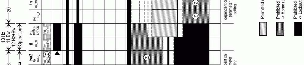
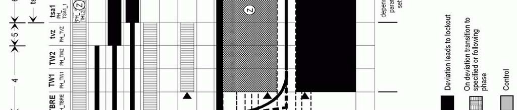
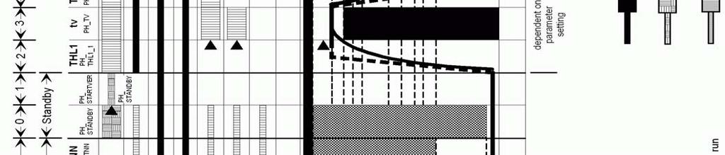
43 Figure Operating phases 37
44 Figure 9.0 Boiler Wiring Schematic 38 PUREWELL VariHeat c /T
45 9.0 FAULT FINDING The Purewell VariHeat boiler is equipped with full self diagnostic fault indication, which is displayed on the screen - refer to section Controls Operation. Should a fault occur which cannot be reset, or a fault repeatedly occurs, contact Hamworthy Heating for assistance. Do not continue to operate or use the boiler as this may cause damage to the boiler or controls. 9.1 Safety Features Summary Safety Temperature Limiter 1 The electronic control thermostat has several safety levels built in such that a controlled shutdown should occur before the limit thermostat is activated. Should these safety levels be overridden (say external pump overrun failure after shutdown) the temperature limit thermostat will trip initiating a boiler shutdown, preventing the boiler from firing. Should the control thermostat fail, causing an overheat condition, the safety temperature limiter will trip thus creating an immediate shutdown regardless of firing mode. An overheat message on the controls fascia will indicate that this condition has occurred. The limiter thermostat is reset by depressing the reset pin protruding through the hole in the centre of the controls fascia. If, after pushing the pin in, the display screen does not reset and the boiler does not light up, it could be that the boiler is still too hot, i.e. the control thermostat has not re-set. An investigation should be carried out to ascertain the reason for the overheating. An obvious reason would be too low a water flow rate through the boiler Flame Probe The flame is under constant supervision by the burner logic controller through use of a flame probe. This is accomplished by measuring the flame's ability to rectify an AC current. If the flame diminishes for whatever reason and the rectified current drops below the controllers minimum (3µA DC), the controller will induce a non-volatile lockout which will require a manual re-set ( on/off button situated on the controls fascia) to re-start the control sequence Fault Finding Procedures General error messages are detailed in section 8 to assist with fault finding. If the boiler still cannot be operated satisfactorily after following the instructions, consult your Hamworthy Heating for assistance. 9.3 Possible Causes of Boiler Lockout 1) Ignition failure due to faulty igniter. 2) Ignition failure due to faulty gas valve. 3) Ignition failure due to No or low gas supply pressure. 4) No ignition due to faulty controller. 5) Ignition failure due to faulty flame probe or sensing circuit. 6) High temperature 7) Unnecessary pressing of reset when boiler is running 10.0 SERVICING Should a fault code appear which cannot be reset, or a fault code repeatedly occurs, contact Hamworthy Heating for assistance. Do not continue to operate or use the boiler as this may cause damage to the controls. A competent person registered for working on non domestic gas appliances should check and ensure that the flue, its support and terminal, the ventilation to the boiler house, safety valve, condensate trap, drain, water filter if fitted, pressure gauge etc., are in a serviceable and working condition, and still comply with the relevant standards and codes of practice - see Section 4 & Appendices 10.1 Regular servicing is recommended, preferably by a Hamworthy appointed person, and at least annually, to ensure trouble free operation. For the Purewell VariHeat, Hamworthy would recommend an additional 6 monthly examination following commissioning, acknowledging site conditions and running hours. Although cleaning of flueways may not be necessary on a yearly basis inspection of the flueways must be undertaken annually and it is important that all controls and safety features are checked for correct operation. NOTE! Measuring flue gas CO 2 and gas temperatures will give an indication of the state of the boiler flueways and waterways. Results should be compared with previously measured values to establish possible loss of efficiency. Should remedial work be carried out on a boiler within a bank of boilers, then the non-firing module must be 39
46 electrically isolated so as to prevent accidental operation., in the event that the installation is required for ongoing heating requirements The procedures detailed relate to a single boiler and must be carried out on all boilers within a bank. Before servicing the boiler, the following procedure must be carried out: - WARNING: Isolate the electrical supply and turn off the gas isolating valve to the boiler being serviced. 1) To remove the front casing door, remove the four 1/4 turn screws securing the fascia moulding. Pivot the fascia moulding about it s bottom edge to 45 degrees and lift off. Store in a safe place to avoid damage. Remove the two 1/4 turn screws (rotate clockwise a 1/4 turn) securing the front casing door and lift off from the front brace. Remove the two 1/4 turn screws fixing the top panel and slide the panel in the direction of the rear of the boiler to disengage from the securing pins on the back panel. 2) Turn off gas service cock. 3) Disconnect the gas valve plug assembly from the gas valve & the low gas pressure switch plug. Disconnect the gas valve inlet flange from the gas valve. Disconnect the 3 & 5 way electrical plugs from the fan body. 4) Disconnect igniter and probe leads. Disconnect the fan/gas valve assembly from the burner body by removing the 4 M8 nuts securing the transition duct to the burner. Carefully place the fan/gas valve to one side. 5) Loosen the 4 - M8 nuts securing the burner clamping flange to the tie rods and carefully remove the clamp. The burner assembly can be removed by withdrawing upwards (care is required when removing the burner as the Hot Surface Igniter element is fragile). Check condition of igniter assembly and probe for damage. Clean as required. Check burner surface and clean using a soft brush if required (if possible use compressed air to blow out the dust inside the burner. A damaged burner must be replaced. 6) Examine the non return valve located in the fan/burner duct for free operation and integrity of the foam seal. Replace if necessary. 7) The procedure to disconnect the fan from the boiler so the fan impellor can be inspected & cleaned using a soft brush & compressed air is as follows. I) For model PV70c/95c/110c (Refer to Figures 11.2.& 11.3 for parts assembled between the gas valve & fan ) A) Disconnect the silicon tube attached to the gas valve. B) Disconnect the gas valve from the air box lid by removing the screws in the square flange of the lid. C) Remove the screws securing the air-box from it s lid. D) Unscrew the screws fixing the venturi to the metal plate molded in the airbox. E) Remove the screws behind the venturi fixing the airbox to the fan. II) For Models PV140c/180c (Refer To Figure 11.4 For Fan/Gas Valve Assembly) remove the screws attaching the metal bracket & plastic venturi to the fan. A) Remove the screws securing the gas valve to the corrugated gas supply pipe. B) The subassembly of gas valve, metal bracket & plastic venturi can be carefully removed for access to the fan The boiler flueways can now be cleaned as follows:- 1) Remove the inspection panel secured to the front base of the boiler must be removed. 2) Using a suitable brush, clean the vertical fins on the castings below the burner. 3) Using a torch, inspect the fin matrix of the secondary heat exchanger situated below the cast iron sections and clean using compressed air or a water hose. Any debris dislodged can be removed from the sump through the inspection panel. 4) Re-assemble the boiler in the reverse order to that shown above. Ensure a new seal is fitted to the top casting / burner joint to maintain a gas tight seal, (see spares list). Ensure that a new seal is fitted to the inspection panel. The boiler s operation may be affected if these seals are do not form a gas tight joint. 5) Re-assemble the burner and clamp plate to the top casting and secure using the M8 nuts and tie rods, ensuring that the joint is sound. Assemble the gas valve, fan, transition duct using new gaskets. Refit the gas inlet flange to the gas valve using a new O ring. Check all gas connections are tightened securely before opening the gas service cock. Re-connect electrical connections. Switch on the electricity supply and re-light the boiler following the procedure detailed in section ) Take exhaust gas readings and compare with section 7.4. Ensure no gas leaks are evident from the gas connections, refer to section 7.1 for procedure. Check thermostat settings and adjust if required. 7) Re-fit casing panels and tidy floor around boiler as necessary. 40
47 11.0 REPLACEMENT OF FAILED COMPONENTS There are a number of components listed below which can be replaced simply and quickly by following the given procedure. In each case carry out the appropriate part of the commissioning procedure & check the operation of each component replaced. See Section 7.3:Commissioning and Testing NOTE: Isolate electrical supply to the boiler and turn off the gas supply after removing controls cover and before commencing any servicing or component exchange procedure Igniter and Flame Probe Assembly Both Igniter and flame probe are secured in the same manner. Reference to Figure 11.1 shows position of igniter assembly. To remove assembly disconnect the plug/socket on the supply lead and remove the screw securing the igniter to the burner front panel. Figure 11.1 shows diagram of igniter assembly and relevant components. Generally remove any loose sooty deposits and clean as required. Before renewing the Hot Surface Igniter ensure the protective sleeve is removed from the new Igniter (care is required as the Igniter element is Fragile). Ensure positions of components are as recommended in Figure Safety Temperature Limiter (Limit Stat) With the boiler front cover removed, the Limit Stat is situated on the rear of the control panel fascia bracket to the left hand side of the main PCB. Remove the 'push on' spade connections from the temperature limiter body noting position of coloured cables. Remove plastic cover (if fitted) and unscrew holding nut to detach temperature limiter from housing. Gently feed the capillary back through the controls bulkhead. Re-set temperature limiter to 95 C. Check the operation of the device by carefully applying a heat source to the bulb. Re-assemble temperature limiter into controls housing ensuring correct cable notation. Refer to Figure Main Gas Valve. NOTE! Hamworthy Heating strongly recommend that a new gas valve assembly is fitted to ensure safe, reliable operation of the boiler. The gas valve is supplied as a factory set component & must not be tampered with. 1) Disconnect the gas valve electrical plug. Remove the four socket head screws securing the gas valve inlet flange. Take the weight of the gas valve and remove the four socket head screws securing the gas valve to the airbox lid (PV70c/90c/110c), welded bracket with pipe (PV140c/PV180c). Withdraw the gas valve. 2) Always fit new O rings to both inlet and outlet when replacing the gas valve. Always test for gas soundness after replacement parts have been fitted. Refer to Section 7.1, if necessary for valve integrity check procedure. 3) Re-light the boiler using instructions on the inside of the door. Check for correct operation. If necessary, refer to Section 7.4 Commissioning the Boiler, for correct procedures Combustion Fan NOTE! To remove the fan, it is necessary to remove the gas valve & airbox (PV70c/90c/110c), or remove the metal bracket fixing the venturi to the fan (PV140/PV180c). Replacement on Models PV70c/PV95c/PV110c 1) Disconnect the gas valve plug assembly from the gas valve. Disconnect the gas valve inlet flange from the gas valve. Disconnect the 3 & 5 way electrical plugs from the fan body. 2) Disconnect the fan/gas valve assembly from the burner body by removing the 4 M8 nuts securing the transition duct to the burner. 3) Remove the screws securing the airbox lid to the airbox and carefully store the lid & gas valve assembly. 4) Note correct orientation of the venturi with baffle & remove the screws of the venturi. Remove the screws securing the airbox to the fan. Carefully store all of the air inlet box components. 5) Remove the screws securing the fan outlet to the burner transition duct. Beware there is a non return valve fitted between these components. 6) Re-assemble in reverse order using new gaskets where appropriate. After assembly and prior to re-fitting the assembly to the burner, check for correct and free operation of the non return valve in the burner transition duct. Replacement on Models PV140c - PV180c 1) Repeat Steps 1 & 2 above. 2) Unscrew the metal bracket from the gas valve & fan. See Figure
48 Figure Hot Surface Igniter and Flame Sensing Probe Positions Venturi Seal Gas Pressure Switch Venturi Gas Valve Figure Gas Valve Assembly Models PV70c 42
 748010342 M8x20 Screw Figure 11.")
49 Fan Burner Elbow Gasket Fan Elbow Seal Flapper Valve HSI Burner Flame Probe Figure Combustion System Assembly PV70c Fan Gas Pressure Switch Gas Valve M5x 12 Screw Gas/Air Mixer (Venturi) M8x20 Screw Figure Combustion System Assembly Model PV70c 43

50 Gas Pressure Switch Fan Gas Valve M5x 12 Screw Gas Valve Mounting Bracket Gas/Air Mixer (Venturi) M8x20 Screw Figure Combustion System Assembly Models PV180c Venturi Seal Gas Pressure Switch Venturi Gas Valve Figure Gas Valve Assembly Models PV 95c/ 110c/ 140c 44

51 Fan Burner Elbow Gasket Fan Elbow Seal Flapper Valve Flame Probe Burner HSI Figure Combustion System Assembly PV 95c/ 110c/ 140c Fan Gas Pressure Switch Gas Valve M6x16 Screw Gas/Air Mixer (Venturi) Figure Combustion System Assembly Model PV 95c/ 110c/ 140c 45
52 Gas Hose (PV70c - PV110c) (PV140c/PV180c) Gas Pipe Ball Valve M8 Flange Nut Test Point QA Label M8x16 Screw Figure Gas Train Assembly /4 Turn Screw Top Cover Back Panel Cable Clip /4 Turn Screw LHS Panel ( RHS) Control Cover /4 Turn Fastener Clip Cable Clip /4 Turn Screw /4 Turn Receptacle Side Rail /4 Turn Screw Front Cover Brace Front Cover Moulding Figure Casing Assembly 46
53 Base Top Clamp Distribution Screen Secondary Heat Exchanger Gasket Door Seal Secondary Heat Exchanger Tube Flange Seal Screw Tube Flange Seal Base Casting Variheat Skid Figure Secondary Heat Exchanger Assembly Flue Spigot Gasket Condensate Section Clamp Combustion Chamber Burner Gasket Thermostat Pocket R1/4 Sensor Pocket Outlet Connection Tie Rod K NTC Temp Sensor Section Seal Water Connection Assembly Heat Exchanger Section Flexible Connector Water Connection Gasket Figure Heat Exchanger Assembly ( model 70c 110c shown for illustration) 47


54 Burner Gasket Combustion Chamber O-ring Tube Section Seal Elbow O-Ring Heat Exchanger Tie Rod Section Flexible Connector Heat Exchanger Water Connection Gasket Figure Heat Exchanger Assembly ( model 140c - 180c shown for illustration) 48
55 12.0 RECOMMENDED SPARES Please Note:- To ensure the correct spare parts are despatched by our spares department, it is imperative that the complete Boiler/Module/Control Panel Serial Numbers are given. The Boiler and Module Serial Numbers are located on the Data Plates affixed to the front of the heat exchanger base casting The Electrical Serial Number is located inside the Control panel on the maximum power rating label. These numbers MUST be quoted when ordering spare parts. SPARES ITEM PART No. ELECTRICAL ITEMS LMU 64 Boiler Controller - 70c LMU 64 Boiler Controller - 95c LMU 64 Boiler Controller - 110c LMU 64 Boiler Controller - 140c LMU 64 Boiler Controller - 180c AGU2.310A109 Display PCB Flow / Return Sensor Temperature Limiter Hot Surface Igniter (HSI) Replacement Kit Flame Sensing Probe T2A 5x20 Fuse T1A 5x20 Fuse MECHANICAL ITEMS Burner Gas Valve (70c) Gas Valve (95c - 110c) Gas Valve O Ring (70c ) Gas Valve O Ring (95c -140c ) Gas Valve (180c) Gas Valve O Ring (140c - 180c) Combustion Fan (70c) Combustion Fan (95c - 140c) Combustion Fan (180c) Low Gas Pressure Switch (70c -140c) Low Gas Pressure Switch (180c) Set of Gaskets (Routine Service - combustion system) Set of Gaskets (Major Service - combustion system plus heat exchanger) For service or spares please contact :- Hamworthy Heating Limited Fleets Corner Poole Dorset BH17 0HH Phone Number Fax Number Service Spares Technical
56 APPENDIX A - GAS DATA Natural Gas GENERAL DATA Purewell VariHeat - non condensing BOILER MODEL Model 70c 95c 110c 140c 180c Boiler Input (maximum) - kw (Gross) Boiler Input (maximum) - kw (Nett) Boiler Output (maximum) 80/60 C - kw Boiler Output (minimum) 80/60 C - kw GENERAL DATA Purewell VariHeat - condensing BOILER MODEL Model 70c 95c 110c 140c 180c Boiler Output (maximum) 50/30 C - kw Boiler Output (minimum) 50/30 C - kw GAS DATA Gas Inlet Connection Pipe Thread Size R1 Nominal Gas Inlet Pressure - mbar 20 Maximum Gas Inlet Pressure - mbar 25 Gas Flow Rate (maximum) - m 3 /h Target CO 2 % at High / Low fire ±0.25% 9.5 / / 8.5 Figure A1 - Gas Data 50
57 APPENDIX B - ELECTRICAL CONNECTIONS AND CONTROLS ELECTRICAL DATA Model 70c 95c 110c 140c 180c Normal Supply Voltage 230V ~ 50Hz Power Consumption (maximum)* - W Start and Run Current (per boiler) - A Figure B1.1 - Electrical Supply *Where The max allowable power output from the IEC Outlet is 460 W (fitted with A T2A fuse). IMPORTANT: Individual boiler modules must be earthed. The boiler must be isolated from the mains electricity supply in the event of electric arc welding being carried out on any connecting pipework. 1.1 Wiring external to the boiler must be installed in accordance with the IEE Regulations and any local regulations which apply. Wiring must be completed in heat resistant 3-core cable of 1.0mm² cross sectional area. Boilers are normally supplied for connection to a 230 volts, 50Hz mains supply. The BIC 930 control is supplied with a replaceable fuse (T1.25A). External fuses should be 10A for all boiler modules Phase Electrical Supplies. Banks of VariHeat boilers and boilers installed in close proximity to each other MUST NOT be supplied from different phases of a 3 phase supply. The method of connection to the mains electricity supply must facilitate complete electrical isolation of the single boiler with a separation of at least 3mm in all poles. 1.3 A mains isolator must be provided adjacent to each boiler in a readily accessible position. The supply should only serve the boiler. 1.4 Volt free contact electrical supplies must be isolatable where fitted. 1.5 Further details regarding connection to the electricity supply are given in BS EN 60335, Part 1. WARNING: THE MAINS POWER SUPPLY MUST NOT BE SWITCHED BY A TIME-CLOCK CONTROL. CAUTION: DO NOT FEED MAINS VOLTAGE ONTO THE TIMER TERMINALS 1.6 The mains power supply must be maintained at all times. Each Purewell VariHeat boiler incorporates a remote stop/start loop, which can be used to operate the boiler(s) under a timed regime. The boiler controls provide a 30V DC signal that can be fed through a volt free contact for operation. Refer to BS 6644 for further information on installing the electrical supply. NOTE: FOR ELECTRICAL CONNECTIONS TO BOILER SEE FIGURE 4.5 FOR BOILER WIRING SCHEMATIC SEE FIGURE 9.0 FOR MULTIPLE BOILER WIRING SEE FIGURE B1.2 & B1.3 FOR CONTROL WIRING SEE FIGURE E1.3.1 TO E


58 Figure B1.2 - External Control Wiring for Multiple Module Installation 52
59 2.0 - Ignition transformer in-line fuse From February 2013 (serial no. ending 8510Q onwards) an in-line fuse has been introduced on the power supply between the ignition transformer and the main LMU. The fuse is rated at T1A (slow blow) and can be located on the control panel as in fig. B2.0 below. The condition of the fuse should be checked when investigating a possible LMU malfunction. HHL part number for spare T1A 5x20 fuse Figure B2.0 In-line Fuse 53
60 APPENDIX C - FLUE DATA Natural Gas FLUE DATA Model 70c 95c 110c 140c 180c Nominal Flue Diameter - mm 150 Pressure (Max) at the boiler flue outlet - Pa/mbar 100 / 1.0 Approx. Flue Gas Temperature 80/60 C - C (Gross) Approx. Flue Gas Temperature 50/30 C - C (Gross) Approx. Flue Gas 9.5% CO 2 - m 3 /h* Figure C1 Flue Data * Note:- Flue gas volumes are corrected to a flue gas temperature of 15 C and barometric pressure of mbar. C1.0 FLUE SYSTEM 1. Detailed recommendations for flue systems are given in BS 6644, and IGE/UP/10. All flue discharges for plant exceeding 135kW net input must comply with the third edition of the 1956 Clean Air Act Chimney Memorandum. WARNING: THE FLUE DISCHARGE FROM A VARIHEAT BOILER WILL GENERATE A PLUME AT THE TERMINAL EXIT. THIS MUST BE CONSIDERED WITH REGARD TO TERMINAL LOCATION AND ADJACENT BUILDING FABRIC. C1.1 General Requirements For single boiler installations only the Purewell VariHeat c series of boilers are designed to be used with a forced draught flue system. Flue systems should be designed in accordance with regulations and with reference to BS 6644 and IGE/UP/10. Open (Natural draught ) Flue. Type B23: Intake from ventilated plant room and discharge via vertical flue. Fig C1.2 The connection to the boiler is suitable for 150mm flue duct, for connection to an open flue (chimney) system. The resistance and maximum length of the flue system components is detailed in Figure C1.1 The following points should be noted: a. Due to the high thermal efficiency of the boiler condensation in the flue will occur. It is strongly recommended that twin wall or insulated flue pipe is used on all external flue installations. b. Care should be taken to ensure that the flue is installed such that any condensation is continuously drained. All flues should have a maximum slope of 2 upwards in the direction of the exhaust gas flow (no horizontal sections). All joints should be such that any condensation is directed back down the slope to an open drain connection in the flue. The drain pipe must be manufactured from a corrosion resistant material and be at least 15mm diameter. It must also have a fall of at least 2-3 (approx mm per meter) and connect to a drain via a waste trap. c. Boiler flue outlet sizes - A flue system designed with the same diameter as the boiler flue outlet may not provide satisfactory performance in all applications. Consideration must be given to the correct calculation of the required flue size. If in any doubt consult Hamworthy Heating Ltd who can supply a full flue design and installation service. C1.2 Waste Gas Volume and Temperature. It is recommended that the volume and temperature of the waste gases used for design of the flue system are as given in Table C1 above. 54
61 C1.3 Materials. Materials used for the flue system must be mechanically robust, resistant to internal and external corrosion, noncombustible and durable under the conditions to which they are likely to be subjected. Consideration must be given to avoid possible freezing of condense water traps and pipework C1.4 Suction The flue system must be designed acknowledging that there is a positive pressure of generated by the boiler combustion fan available to the flue system. It is recommended that a draught stabiliser is fitted to the flue system where the draught is likely to become ve at the boiler connection. C1.5 Disconnection Provisions should be made for disconnection of the flue pipe for servicing. It is advisable that bends are fitted with removable covers for inspection and cleaning as appropriate. WARNING: THE FLUE SYSTEM MUST BE SELF SUPPORTING AND NOT PRESENT A RISK TO PEOPLE IN OR AROUND THE BUILDING. C1.6 Flue Discharge The flue system must ensure safe and efficient operation of the boiler to which it is attached, protect the combustion process from wind effects and disperse the products of combustion to the external air. The flue must terminate in a freely exposed position and be so situated as to prevent the products of combustion entering any opening in a building. Where the flue diameter is less than 204mm (8 ) diameter a terminal must be fitted. Where the flue is of a larger size, consideration should be given to the fitting of a flue discharge terminal or grille to stop ingress of birds etc. C1.7 Surface Temperatures Combustible materials in the vicinity of the boiler and flue shall not exceed 65 C during boiler operation. The flue shall not be closer than 50mm to any combustible material, except where it passes through such material with a non-combustible sleeve when the air gap may not be less than 25mm. C1.8 Location The flue system must not be placed or fitted where there is undue risk of accidental damage to the flue pipe or undue danger to persons in the vicinity. Check that the flue and chimney are clear from any obstruction. Purewell VariHeat boilers are suitable for installation in a balanced compartment in accordance with the requirements of BS Consult Hamworthy Heating Technical Department for help or assistance if in doubt. C1.9. Condensate Discharge Due to the high thermal efficiency of the boiler, condensation will occur within the boiler casing during firing from cold conditions. A drain with an integral trap is fitted to the rear of each module suitable for connection to a 32mm plastic waste pipe (not Hamworthy Heating Ltd supply), which must be connected to a tundish (not Hamworthy Heating Ltd supply). Discharge piping from a tundish should be of synthetic material due to the mild acidity of the condensate (ph 3-5), with all discharge piping having a minimum fall of 30mm/m away from the boiler. Consideration should be given to possible freezing of condense water traps and pipework. This must be avoided at all times by routing pipework within the building, where possible. It is strongly recommended that on modular installations, the common header and chimney system must have separate drains for condensate disposal - refer to section
62 Model Component 70c 95c 110c 140c 180c Straight tube ø150mm maximum length (m) bend ø150mm Equivalent tube length (m) bend ø150mm Equivalent tube length (m) Figure C1.1 - Flue Resistance Figure C1.2 - Open (Natural Draught) B23 Flue System 56
63 APPENDIX D - VENTILATION D1.1 Air Supply Detailed recommendations for air supply are given in BS The following notes are intended to give general guidance. In all cases there must be provision for an adequate supply of air for both combustion and general ventilation, in addition to that required for any other appliance. Combustion air for the boiler is drawn through the rear of the boiler casing. The area must be kept open and free from blockage at all times. D1.2 Air Supply by Natural Ventilation The boiler room must have, or be provided with, permanent air vents directly to the outside air, at high level and at low level. For an exposed boiler house, air vents should be fitted, preferably on all four sides, but at the least on two sides. Air vents should have negligible resistance and must not be sited in any position where they are likely to be easily blocked or flooded or in any position adjacent to an extraction system which is carrying flammable vapour. Grilles or louvres must be so designed that high velocity air streams do not occur within the space housing the boiler. The air supplied for boiler house ventilation shall be such that the maximum temperatures within the boiler house shall be as follows; 1) At floor level (or 100mm above floor level) = 25 C 2) At mid-level (1.5m above floor level) = 32 C 3) At ceiling level (or 100mm below ceiling level) = 40 C. Where both low and high level openings are used, the grilles shall have a total minimum free area of: Low level (inlet) cm² per kilowatt of total rated net heat input. High level (output) cm² per kilowatt of total rated net heat input. If the boilers are to operate during the summer months for 75% of the time a further 1 cm² or for 100% of the time a further 2 cm² should be added per kw to both high & low openings. D1.3 Air Supply by Mechanical Ventilation Air supplied to the boiler room by Mechanical means should be as follows: 1) Mechanical ventilation must be interlocked with the boilers to prevent operation in the event of ventilation fan failure 2) Mechanical inlet and mechanical extract can be utilised providing the design extraction rate does not exceed one third of the design inlet rate. 3) Mechanical extract ventilation with natural inlet ventilation MUST NOT be used. Figure D1 Mechanical Ventilation Flow Rates Boilers Without Draught Diverters Flow rate per kw total rated heat input (net) Inlet air (Combustion ventilation) m³/h Difference between inlet and extract air (Inlet minus extract ventilation) m³/h Volume /
64 APPENDIX E - WATER DATA WATER DATA Model 70c 95c 110c 140c 180c Water Connections (Flow & Return) R2 male Maximum Water Pressure - bar g 6 Water Content (not including headers) - litres System Design Flow 11 C T Rise - litre/s Minimum Flow 20 C T Rise - litre/s Waterside Pressure 11 C T Rise - mbar Waterside Pressure 20 C T Rise - mbar Figure E1 - Water Data E1.1 Water Circulation System The Purewell VariHeat boiler has a low water content and the requirements of minimum water flow are given in the above table. Recommendations for the water circulation system are given in BS The following details are of particular importance for the correct installation of the water circulation system: 1) In a combined central heating and hot water system the hot water storage vessel must be of the indirect cylinder or calorifier type. The hot water storage vessel should be insulated, preferably with not less than 75mm (3 ) thick mineral fibre, or its thermal equivalent. 2) Circulating pipework not forming part of the useful heating surface should be insulated to help prevent heat loss and possible freezing, particularly where pipes are run through roof spaces and ventilated cavities. Cisterns situated in areas which may be exposed to freezing conditions should also be insulated. Furthermore, insulation exposed to the weather should be rendered waterproof. 3) Drain valves must be located in accessible positions which permit the draining of the whole system, including the boiler and hot water storage vessel. 4) Each boiler module has R2 male flow (indicated with a red spot) and return (indicated with a blue spot) connections. Boilers should be connected by flow and return headers. Headers should be connected to the system in a reverse / return arrangement (the water flow in each header is in the same direction) to ensure equal flow in each module, or with a single pipe header system. Figure E1.2 on the following page show typical layouts. 5) Ideally, individual valves should be fitted to each module to enable isolation from the system, however, the arrangement must comply with the requirements of BS E1.2 Minimum System Water Pressure To comply with guidance note PM5 (Health and Safety Executive), the minimum pressure requirements at the boiler are given below as examples:- 1) Single installed boiler running at 82 C flow temperature. Minimum head required is not less than 2.0 metres or 0.2 bar. 2) Single installed boiler running at 90 C flow temperature. Minimum head required = 3.0 metres or 0.30 bar. 3) Modular boiler installation running at 82 C flow temperature and 11 C rise across system. Minimum head required = 4.4 metres or 0.43 bar. 4) Modular boiler installation running at 82 C flow temperature and 15 C rise across system. Minimum head required = 6.5 metres or 0.64 bar. E1.3 Pressure Relief Valve (Safety Valve) The most important single safety device fitted to a boiler is its safety valve. Each boiler module is provided with a capped R1 stub pipe for the fitting of a safety valve (not supplied). BS 6644 provides comprehensive information for the selection and location of safety valves and attention is drawn to the higher capacity requirements of safety valves for pressurised hot water systems. Boiler Output Feed mm Vent mm kW kw kw Figure E1.1 Cold Feed and Vent Pipe Sizes 58


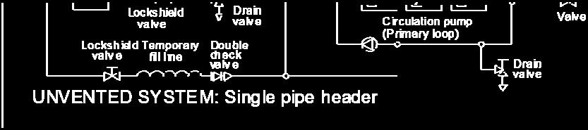
65 Figure E1.2 - Typical Piping Layouts 59
66 E1.4 Open Vent and Cold Feed Pipe. Every boiler or group of boilers should have an open vent pipe and cold feed pipe installed between the boiler and the first water isolating valve. The minimum bore (mm) of these pipes per installation is shown in the table. The vent pipe must rise continually, any valve fitted between a boiler and the open vent pipe for maintenance purposes shall be of the 3 way type such that when closed to the vent pipe the boiler will be open to atmosphere. The vent pipe shall be protected against freezing where this might occur. See BS 6644 for detailed information on Open Vent and Cold Feed Pipes. E1.5 Altitude Gauge (Water Pressure Gauge) Every boiler or group of boilers should be provided with an altitude gauge complete with isolating valve. See Figure E1.2 for typical position. E1.6 Thermometer A thermometer complete with pocket should be fitted in the pipework to indicate water flow temperature. See Figure E1.2 for typical position. E1.7 Drain Valves Each boiler is fitted with a 15mm NB drain valve in the boiler return to drain the boiler only. The heating system in total should have drain valves as recommended by BS See Figure E1.2 for typical position. E1.8 Circulating Pump One or more circulating pumps will be required to circulate water around the boilers and heating system. The pump should be sited to facilitate servicing. It is important that when Purewell VariHeat boilers are used to replace boilers on an existing system, the pumps should be checked for performance against the new boiler waterside pressure loss to ensure that the minimum flow rate can be obtained. It is also important that the existing system be flushed through twice to remove any loose matter which may have accumulated. If in any doubt regarding the cleanliness of the system, a coarse filter should be fitted in the return pipework to the boilers. If boiler / system pump(s) are not controlled by the boiler, a pump overrun (not Hamworthy Heating Ltd supply) should be fitted which must run for a minimum of 5 minutes on shutdown of the last boiler. E1.9 Minimum Water Flow Rates Minimum water flow rates are shown in table at beginning of Appendix E. These flow rates should be maintained through the boiler at all times whilst the boiler is firing. If the water flow rate is allowed to fall below the minimum the boiler heat exchanger could fail due to the resultant scale formation. Particular attention should be paid to the restriction of external flow circuits during periods of low heat demand. E1.10 Waterside Pressure Drop The waterside hydraulic resistance (Pressure drop) is given in table E1 at beginning of Appendix E. E1.11 Water Flow Controls Any external mixing valve / shunt pump or similar controls MUST always ensure that the minimum water flow rate as given in table at beginning of Appendix E is maintained. If there is any doubt relating to site flow conditions it is suggested that a flow switch is fitted. The flow switch should be connected such that the boiler will shut down if insufficient flow occurs. E1.12 Frost Protection Consideration should be given to fitting a frost thermostat set at approximately 4 C E1.13 Unvented Systems Refer to Figure E1.2 for typical layout of an unvented (Pressurised) Hot Water System. For system design refer to BS 7074 Part 2. In order to correctly size a pressurisation unit for any heating system the following parameters 60
 Maximum flow temperature ( C) 4) Maximum system hot working pressure, generally given in bar gauge.")

67 are required. 1) Static height of highest component in system (metres) 2) System volume. If this is not known, a general rule of thumb of 10litres/kW of installed boiler power can be used. 3) Maximum flow temperature ( C) 4) Maximum system hot working pressure, generally given in bar gauge. From the parameters given, Hamworthy Heating can size the pressurisation unit and also the expansion vessel required. Care must be taken in sizing expansion vessels to ensure maximum acceptance factors are not exceeded. Normally manufacturers of vessels impose a limit of 0.5. This value must not be exceeded at any time during the operation of the boiler, this includes the over pressure condition should a safety valve lift. Consideration should also be given to sizing of the safety valve(s) in the system. Refer to BS 6644: Part 1 for further information and to BS 6880: Part 1 for design considerations. Figure E Schematic for Single Boiler System QAC34 (HHL ) Figure E Schematic for Single Boiler, Primary Circuit System 61
Wessex ModuMax mk3 Boilers
 Wessex ModuMax mk3 Boilers Condensing Fully Modulating, Pre-Mix, Gas Fired, Modular Boilers for Heating and Domestic Hot Water Installations Installation, Commissioning and Servicing Instructions Models
Hamworthy Fleet Vertical Floor Standing. Condensing Boilers Natural Gas Outputs 80kW to 1050kW 5 YEAR HEAT EXCHANGER WARRANTY
 Hamworthy Fleet Vertical Floor Standing Condensing Boilers Natural Gas Outputs 80 to 1050 5 YEAR HEAT EXCHANGER WARRANTY Fleet V Floor Standing Vertical Boilers The Fleet range of commercial boilers has
Hamworthy. Wessex Modumax. High Efficiency, Fully Modulating Boilers Condensing & Non Condensing, Pre-mix, Gas Fired. Outputs 100kW to 750kW
 Hamworthy Wessex Modumax High Efficiency, Fully Modulating Boilers Condensing & Non Condensing, Pre-mix, Gas Fired Outputs 100kW to 750kW Wessex ModuMax High Efficiency, Condensing Compact space saving
Hamworthy. Purewell VariHeat
 up to Seasonal efficiency (gross) Hamworthy Purewell VariHeat High Efficiency, Fully Modulating Boilers Condensing & Non Condensing Cast Iron, Pre-mix, Modular Gas Fired Single Boiler Outputs 65kW to 180kW
ATMOSPHERIC GAS BOILER INSTALLATION, OPERATING AND MAINTENANCE MANUAL
 STREBEL GENEVA CE ATMOSPHERIC GAS BOILER INSTALLATION, OPERATING AND MAINTENANCE MANUAL INDEX TABLE 1 TECHNICAL DATA SECTION 1 SECTION 2 SECTION 3 SECTION 4 SECTION 5 SECTION 6 SECTION 7 SECTION 8 SECTION
USER GUIDE. IMAX XTRA EL kW. For Installation Guide see reverse of book
 USER GUIDE IMAX XTRA EL 320-620kW For Installation Guide see reverse of book When replacing any part on this appliance, use only spare parts that you can be assured conform to the safety and performance
ProCon Boiler Controller Commissioning Quick Reference Guide
 ProCon Boiler Controller Commissioning Quick Reference Guide This sheet is intended as a quick reference guide and should be read in conjunction with the operating and maintenance manual for the boiler
Quickheat 30 weather compensated boiler control
 Quickheat 0 weather compensated boiler control A compact and sophisticated heating controller The compact KM controller is designed for the control of fan assisted boilers with modulating burners. The
Hamworthy Fleet Horizontal Floor Standing. Condensing Boilers Natural Gas Outputs 40kW to 350kW 5 YEAR HEAT EXCHANGER WARRANTY
 Hamworthy Fleet Horizontal Floor Standing Condensing Boilers Natural Gas Outputs 40kW to 350kW 5 YEAR HEAT EXCHANGER WARRANTY Fleet H Floor Standing Horizontal Boilers The Fleet range of commercial boilers
ProCon 16, 31, 47 & 75. RVA 63 Boiler and Circuit Controller Commissioning Data.
 ProCon 16, 31, 47 & 75. RVA 63 Boiler and Circuit Controller Commissioning Data. The RVA63 controller can be utilized to control the following system configurations via LPB communication. Equipment Required
Hamworthy. Stratton Wall Hung. Stainless Steel Condensing Boilers Natural Gas or LPG Outputs 45kW to 100kW
 Hamworthy Stratton Wall Hung Stainless Steel Condensing Boilers Natural Gas or LPG Outputs 45kW to 100kW Stratton Wall Hung, Pre-mix Gas Fired Modular Boilers The new Stratton boiler from Hamworthy brings
Contents. 1 General Appliance Type Single Units Cascade Manager Units Cascade Slave Units...
 1 Contents 1 General... 3 1.1 Appliance Type... 3 1.1.1 Single Units... 3 1.1.2 Cascade Manager Units... 4 1.1.3 Cascade Slave Units... 4 2 Installation... 5 2.1 Installation Regulations and Requirements...
TABLE OF CONTENTS TECHNICAL DOCUMENTATION 03. Technical Data
 INSPIRED EF F ICIENCY CONDENSING BOILERS ETHOS 350 & 550 FLO O R ST AN D I N G CO N DE N SI N G BOI L E R S T ECHN I CAL DO CUME N TA T I O N I SSUE 0 3 /1 6 R e v. 0 1 TABLE OF CONTENTS 1. 2. 3. 4. 5.
Heat 45 & 55. User Instructions FAN POWERED HIGH EFFICIENCY MODULATING DOMESTIC CONDENSING GAS COMBINATION BOILER
 Heat 45 & 55 User Instructions FAN POWERED HIGH EFFICIENCY MODULATING DOMESTIC CONDENSING GAS COMBINATION BOILER CE/PI No. 86-CN-69 Heat 45 - GC No. 41-930-40 Heat 55 - GC No. 41-930-41 These instructions
Hamworthy. Fleet Wall Hung. Condensing Boilers Natural Gas Outputs 40kW to 150kW 5 YEAR HEAT EXCHANGER WARRANTY
 Hamworthy Fleet Wall Hung Condensing Boilers Natural Gas Outputs 40kW to 150kW 5 YEAR HEAT EXCHANGER WARRANTY Fleet Wall Hung Boilers The Fleet range of commercial boilers has been designed by Hamworthy,
Hamworthy. Stratton Wall Hung. Stainless Steel Condensing Boilers Natural Gas or LPG Outputs 45kW to 100kW
 Hamworthy Stratton Wall Hung Stainless Steel Condensing Boilers Natural Gas or LPG Outputs 45kW to 100kW Stratton Wall Hung, Pre-mix Gas Fired Modular Boilers The new Stratton boiler from Hamworthy brings
JANUS 3 CIRCULATOR WATER HEATER INSTALLATION, COMMISSIONING & SERVICING INSTRUCTIONS G.C. No
 JANUS 3 CIRCULATOR WATER HEATER INSTALLATION, COMMISSIONING & SERVICING INSTRUCTIONS G.C. No 53 416 06 Publication No. ZZ 180/17 May 2000 These appliances are tested and certified by B G Technology for
Cast Iron Boilers. G Series ( kW)
") Cast Iron Boilers G Series (320-1017kW) Mikrotherm G Series Cast Iron Boilers The Mikrotherm G Series of cast iron sectional boilers offer all the advantages of cast iron durability and longevity coupled
Cast Iron Boilers G Series (320-1017kW) Mikrotherm G Series Cast Iron Boilers The Mikrotherm G Series of cast iron sectional boilers offer all the advantages of cast iron durability and longevity coupled
Clyde CK40. Cast Iron Boiler. Engineering Data Sheet 663/8 May Natural gas Class D oil Dual Fuel. 350 kw to 500 kw
 atural gas Class D oil Dual Fuel 350 kw to 500 kw Clyde CK40 Cast Iron Boiler Contents Page General information Dimensions 3 Technical data 3 Installation requirements 4 & 5 Boiler control panel 6 Wiring
ProCon 16, 31, 47, 75, 77 & HT. RVA 46. Zone Controller Commissioning Data.
 ProCon 16, 31, 47, 75, 77 & HT. RVA 46. Zone Controller Commissioning Data. The RVA 46 Zone Controller can only be used in conjunction with a RVA47 controlled boiler installation. The RVA46 controller
prestige Condensing Water Boiler SERVICE TECHNICIAN S TROUBLE SHOOTING GUIDE TSG-SOLO-9/04
 prestige Condensing Water Boiler SERVICE TECHNICIAN S TROUBLE SHOOTING GUIDE 2004-28 TSG-SOLO-9/04 Table of Contents INTRODUCTION Page 1 SERVICING TIPS AND INSTRUCTIONS Page 3 CONTROL MODULE DISPLAY -
Installation and Operating Manual for the EcoStar 500 Oil Condensing Floor Standing Range Output Range kw
 Installation and Operating Manual for the EcoStar 500 Oil Condensing Floor Standing Range Output Range 15.5 28.4 kw 1 Section 1.0 Appliance Type 1.1 ECOSTAR 500 Standard 1.2 ECOSTAR 500 Enhanced 2.0 Installation
Superior. A Compact Floor Standing Gas Fired, High Efficiency Condensing Hot Water Boiler. Outputs 120, 160, 200, 240, 280 kw
 Superior A Compact Floor Standing Gas Fired, High Efficiency Condensing Hot Water Boiler Outputs 120, 160, 200, 240, 280 kw 1 The Superior is a, pre-assembled floor standing, gas fired high efficiency
Installation, operating and servicing instructions
 English 57-115 - 144-1 - 259 Installation, operating and servicing instructions ITALIA EN 1 ITALIA English INDEX WARnINGS 3 Who should read these instructions 3 Symbols 3 Recommendations 3 Importants notes
Mikrofill Ethos Condensing combination boiler. Maintenance Instructions 24cc
 Mikrofill Ethos Condensing combination boiler Maintenance Instructions 24cc IMPORTANT Benchmark Installation, Commissioning and Service Record Log Book is enclosed in your customer information pack. This
ProCon Streamline Gas Condensing Boiler. Installation and Operating Manual.
 1 MHG Heating Ltd ProCon Streamline Gas Condensing Boiler. Installation and Operating Manual. Unit 4 Epsom Downs Metro Centre, Waterfield, Tadworth, Surrey, KT20 5LR Telephone 08456 448802 Fax 08456 448803
Aqua Balance. AquaBalance TM CONTROL MODULE QUICK START GUIDE LEGEND
 Aqua Balance AquaBalance TM CONTROL MODULE QUICK START GUIDE 10 1 Domestic Hot Water temperature setpoint decreasing button 2 Domestic Hot Water temperature setpoint increasing button 3 Central Heating
12.0 Servicing. Electrode Position Fig Annual Servicing Inspection (Cont) 4 ±0.5
 4 ±0.5") 4 ±0.5 12.0 Servicing 12.2 Annual Servicing Inspection (Cont) Flame Sensing 5 ±1 10 ±1 Position Fig. 45 Spark Ignition 5. Remove the clip securing the gas feed pipe to the air/gas venturi. Disconnect the
4 ±0.5 12.0 Servicing 12.2 Annual Servicing Inspection (Cont) Flame Sensing 5 ±1 10 ±1 Position Fig. 45 Spark Ignition 5. Remove the clip securing the gas feed pipe to the air/gas venturi. Disconnect the
SIME FORMAT WALL HUNG BOILERS MODEL 34i AND MODEL 34e. cod A
 cod. 6272262A GENERAL DATA Heating Data Heat Output Input (Adjustable) (Adjustable) Format 34i 11.2 34KW 45 145MJ/hr Format 34e 11.2 34KW 45 145MJ/hr General Specifications FORMAT 34i 34e Main burner injectors
TABLE OF CONTENTS TECHNICAL DOCUMENTATION 03. Technical Data
 INSPIRED EF F ICIENCY CONDENSING BOILERS ETHOS 70, 90, 1 10 & 130 W ALL MO UN T ED CO N D EN SI N G BO I L E R S T ECHN I CAL DO CUME N TA T I O N I SSUE 1 0 /1 7 Re v. 0 3 TABLE OF CONTENTS 1. 2. 3.
Hamworthy. Varmax. New. Fully modulating, low NOx, stainless steel, condensing boilers Natural Gas or LPG Outputs 120kW to 900kW
 New Twin return connections Wide differential temperature up to Seasonal efficiency (gross) Hamworthy Varmax Fully modulating, low NOx, stainless steel, condensing boilers Natural Gas or LPG Outputs 120kW
95% Hamworthy Fully Modulating, Low NOx, Stainless Steel, Condensing Modular Boilers. Wessex ModuMax mk3. New. Restyled with latest Siemens controls
 New Restyled with latest Siemens controls 40 C ΔT ErP & Part L 2013 Compliant up to 95% Seasonal efficiency (gross) Hamworthy Fully Modulating, Low NOx, Stainless Steel, Condensing Modular s Available
Compact HE. High efficiency combi boiler. Installation & Servicing Instructions THESE INSTRUCTIONS TO BE RETAINED BY USER
 Compact HE High efficiency combi boiler Installation & Servicing Instructions THESE INSTRUCTIONS TO BE RETAINED BY USER Vokèra is a licensed member of the Benchmark scheme which aims to improve the standards
Powerstock Storage Tank
 Powerstock Storage Tank Models ST300, ST500, ST750 & ST1000 INSTALLATION, COMMISSIONING AND SERVICING INSTRUCTIONS THE POWERSTOCK STORAGE TANK IS INTENDED FOR USE AS A COMMERCIAL APPLIANCE. PUBLICATION
M116 / M450 USER AND MAINTENANCE MANUAL FOR MODULATING-CONTROL BOILER WITH GAS BURNER EQUIPPED FOR NATURAL GAS. Type : B23 ATLANTIC 2000
 M SERIES M116 / M45 USER AND MAINTENANCE MANUAL FOR MODULATING-CONTROL BOILER WITH GAS BURNER EQUIPPED FOR NATURAL GAS Type : B23 Country BE CH ES FR GB IE IT LU NL PT Category I2E(R)B I2H I2H I2Esi I2H
Osprey 2 CFL
 Osprey 2 CFL 125-150 - 180-220 Gas Fired Floor Standing Boiler Installation and Servicing Instructions Please leave these instructions with the user Natural Gas Potterton Osprey 2 CFL 125 G.C.N o 41 590
Servicing manual. Wall-mounted condensing gas boiler 600 Series - 11S / 19S / 24S / 24C /2002 GB(EN) For trade use
 For trade use") GB122 7210 1300-12/2002 GB(EN) For trade use Servicing manual Wall-mounted condensing gas boiler 600 Series - 11S / 19S / 24S / 24C Please read thoroughly before attempting to diagnose fault List of contents
GB122 7210 1300-12/2002 GB(EN) For trade use Servicing manual Wall-mounted condensing gas boiler 600 Series - 11S / 19S / 24S / 24C Please read thoroughly before attempting to diagnose fault List of contents
Bosch Group. 15SBi / 24SBi. WALL MOUNTED BOILERS FOR CENTRAL HEATING and Indirect supply of domestic hot water
 Bosch Group 15SBi / 24SBi WALL MOUNTED BOILERS FOR CENTRAL HEATING and Indirect supply of domestic hot water INSTALLATION AND SERVICING INSTRUCTIONS 24SBi This appliance is for use with Natural Gas or
Servicing manual. 600 Series - 11S / 19S / 24S / 24C. Wall-mounted condensing gas boiler. For trade use
 GB122 Servicing manual Wall-mounted condensing gas boiler 600 Series - 11S / 19S / 24S / 24C For trade use Please read thoroughly before attemting to diagnose fault 7217 4900 (03/2010) GB/IE List of contents
Baxi Maxflow Combi WM
 Baxi Maxflow Combi WM Gas Fired Wall Mounted Combination Boiler with Unvented Hot Water Storage Please keep these instructions safe. Should you move house, please hand them over to the next occupier. User
BAXI BOSTON ALL MODELS FLOOR STANDING OPEN FLUE (OF) CENTRAL HEATING BOILERS INSTALLATION AND SERVICING INSTRUCTIONS. GAS TYPE G20 (Natural Gas)
 CENTRAL HEATING BOILERS INSTALLATION AND SERVICING INSTRUCTIONS. GAS TYPE G20 (Natural Gas)") BAXI BOSTON ALL MODELS FLOOR STANDING OPEN FLUE (OF) CENTRAL HEATING BOILERS INSTALLATION AND SERVICING INSTRUCTIONS GAS TYPE G20 (Natural Gas) BAXI BOSTON 80 OF G.C. No 41 077 65 BAXI BOSTON 70 OF G.C.
BAXI BOSTON ALL MODELS FLOOR STANDING OPEN FLUE (OF) CENTRAL HEATING BOILERS INSTALLATION AND SERVICING INSTRUCTIONS GAS TYPE G20 (Natural Gas) BAXI BOSTON 80 OF G.C. No 41 077 65 BAXI BOSTON 70 OF G.C.
prestige Condensing Water Boiler SERVICE TECHNICIAN S TROUBLE SHOOTING GUIDE TSG-PRESTIGE Date revised: 11/10/08
 prestige Condensing Water Boiler SERVICE TECHNICIAN S TROUBLE SHOOTING GUIDE Date revised: 11/10/08 2008-36 TSG-PRESTIGE Table of Contents INTRODUCTION Page 1 SERVICING TIPS AND INSTRUCTIONS Page 3 CONTROL
Hamworthy. Dorchester DR-SA & DR-SE Fully Automatic and Permanent Pilot Direct Gas-Fired Storage Water Heaters. Exceeds Minimum Requirements
 Exceeds Minimum Requirements Hamworthy Dorchester DR-SA & DR-SE Fully Automatic and Permanent Pilot Direct Gas-Fired Storage Water Heaters 18.9 kw to 20.1 kw, Natural Gas or LPG Continuous outputs 369
Forced draught gas burner
 Installation, use and maintenance instructions Forced draught gas burner Code Model Type 3751982 GAS 3 519T80 291 (3) - 02/2010 DECLARATION Declaration of conformity in accordance with ISO / IEC 17050-1
Concord Super Series 4
 Concord Super Series 4 Installation, Commissioning and Servicing Instructions 50 to 600 Vertical and 250 to 600 Horizontal Modular Gas Fired Boilers Assembly and Installation Instructions for Ideal Concord
400G/L PX (CF) Servicing Instructions. For use in GB and IE PLEASE READ THESE INSTRUCTIONS BEFORE SERVICING THIS APPLIANCE
 Servicing Instructions. For use in GB and IE PLEASE READ THESE INSTRUCTIONS BEFORE SERVICING THIS APPLIANCE") Servicing Instructions 400G/L PX (CF) For use in GB and IE DESN 511420 C Remember, when replacing a part on this appliance, use only spare parts that you can be assured conform to the safety and performance
Servicing Instructions 400G/L PX (CF) For use in GB and IE DESN 511420 C Remember, when replacing a part on this appliance, use only spare parts that you can be assured conform to the safety and performance
Alpha CombiMax 350 and 600
 Installation and Servicing Instructions Alpha CombiMax 350 and 600 Unvented Hot Water Store for use with the Alpha 240/280 Range of Gas Fired Combination Boilers For Technical help or for Service call...
GAS FIRED ATMOSPHERIC ELECTRONIC VERSION kw
 GAS FIRED ATMOSPHERIC ELECTRONIC VERSION 51-102 kw GENERAL DESCRIPTION 900 D a3 1000 762 672 E 222 The PEGASUS F2 range of atmospheric natural gas-fired boilers are constructed of cast iron finned sections
Installation and Servicing Instructions. Alpha CB50
 Installation and Servicing Instructions Alpha CB50 Wall Mounted, Fan Assisted, Room Sealed, Gas Fired Combination Boiler with Unvented Hot Water Storage For Technical help or for Service call... ALPHA
Compact. Installation & Servicing Instructions THESE INSTRUCTIONS TO BE RETAINED BY USER
 Compact Installation & Servicing Instructions THESE INSTRUCTIONS TO BE RETAINED BY USER Contents Design principles and operating sequence Page 1.1 Principle components 2 1.2 Central heating mode 2 1.3
Enzo Concealed Shower Mixing Valve
 Enzo Concealed Shower Mixing Valve EZ40010CP, EZ40013CP & EZ40014CP Installation and Maintenance Instructions In this procedure document we have endeavoured to make the information as accurate as possible.
95M-200. Gas-Fired Direct Vent Modulating Hot Water Boiler. Control Manual And Troubleshooting Guide. P/N , Rev.
 95M-200 Gas-Fired Direct Vent Modulating Hot Water Boiler Control Manual And Troubleshooting Guide P/N 24000604, Rev. C [04/09] WARNING! Revise boiler control parameters only if you fully understand the
Hamworthy. Melbury HE. High Efficiency Steel Shell Power Flame Boilers Gas, Oil, Biofuel or Dual Fuel Burners. Outputs 530kW to 10000kW
 Hamworthy Melbury HE High Efficiency Steel Shell Power Flame Boilers Gas, Oil, Biofuel or Dual Fuel Burners Outputs 530 to 10000 Melbury HE High Efficiency Steel Shell Boilers Gas, Oil, Biofuel or Dual
400GL PX (PF) Servicing Instructions. For use in GB and IE PLEASE READ THESE INSTRUCTIONS BEFORE SERVICING THIS APPLIANCE
 Servicing Instructions. For use in GB and IE PLEASE READ THESE INSTRUCTIONS BEFORE SERVICING THIS APPLIANCE") Servicing Instructions 400GL PX (PF) For use in GB and IE DESN 512548 A Remember, when replacing a part on this appliance, use only spare parts that you can be assured conform to the safety and performance
Servicing Instructions 400GL PX (PF) For use in GB and IE DESN 512548 A Remember, when replacing a part on this appliance, use only spare parts that you can be assured conform to the safety and performance
Control Application. Supplement - ACVMax
 prestige Control Application Supplement - ACVMax L I S T E D WARNING This document is intended to be used by a factory trained and qualified heating contractor or service technician only. Read all instructions
Baxi Maxflow Combi FS
 Baxi Maxflow Combi FS Gas Fired Floor Standing Combination Boiler with Unvented Hot Water Storage Please keep these instructions safe. Should you move house, please hand them over to the next occupier.
Power Flame Incorporated
 Power Flame Incorporated SUGGESTED SPECIFICATION FOR MODEL NVC ULTRA LOW NOx GAS BURNERS SUB 9 PPM NOx THE POWER TO MANAGE ENERGY 2001 South 21st Street, Parsons, Kansas 67357 Telephone: 620-421-0480,
Installation and Operating Manual for the ProCon 47, 75 & 77 Wall Mounted Condensing Boiler Range
 Installation and Operating Manual for the ProCon 47, 75 & 77 Wall Mounted Condensing Boiler Range 1 Section Page # 1.0 Appliance Type 3 2.0 Installation Regulations and Requirements 4 2.1 Appliance Warranties
CARVER CASCADE 2 & CASCADE 2 GE CARAVAN WATER HEATER INSTALLATION INSTRUCTIONS LEAVE THESE INSTRUCTIONS WITH THE USER
 CARVER - CASCADE 2 & CASCADE 2 GE CARAVAN WATER HEATER INSTALLATION INSTRUCTIONS LEAVE THESE INSTRUCTIONS WITH THE USER 1:0 SPECIFICATIONS Water capacity Water connections Water supply 9 litres (2 gallons)
Enzo and Enzo Deluxe Safe Touch Thermostatic Shower EN10031CP & EN10035CP
 Enzo and Enzo Deluxe Safe Touch Thermostatic Shower EN10031CP & EN10035CP Installation and Maintenance Instructions In this procedure document we have endeavoured to make the information as accurate as
Inta City Concealed Shower Mixing Valve CT80010CP
 Inta City Concealed Shower Mixing Valve CT80010CP Installation and Maintenance Instructions In this procedure document we have endeavoured to make the information as accurate as possible. We cannot accept
Sirius FS. Working towards a cleaner future
 Sirius FS Floor Standing Stainless Steel Condensing Boilers Single Boiler Applications: 50 to 160kW Modular Boiler Applications: up to 640kW Working towards a cleaner future heating specialists 1. Product
CaterSense 03 & ATSC-02-xx
 CaterSense 03 & ATSC-02-xx GAS SUPPLY INTER-LOCK STATION with INBUILT FAN SPEED CONTROL & CO 2 MONITORING (Optional Gas Pressure Proving) INSTALLATION and COMMISSIONING INSTRUCTIONS CS-ATSC-INST-CO2 Page
RVA /109. Heating Circuit ZONE Controller. Instructions for the INSTALLER
 Heating Circuit ZONE Controller RVA 46.531/109 Zonal temperature controller for control of a lowtemperature heating system, for use with condensing gas boilers Instructions for the INSTALLER INDEX Page
INSTALLATION AND SERVICING
 INSTALLATION AND SERVICING IMAX XTRA E80 E120 E160 E200 E240 E280 For Users Guide see reverse of book When replacing any part on this appliance, use only spare parts that you can be assured conform to
CAST IRON PREMIX HIGH EFFICIENCY GAS FIRED BOILER kw BRILEY DESIGN MANUAL
 BRILEY CAST IRON PREMIX HIGH EFFICIENCY GAS FIRED BOILER 60 140 kw 0604.2 Beeston Briley cast-iron premix gas-fired boiler 60-140kW Contents 1 Boiler specifications Page 3 2 Appliance general dimensions
MODEL SF-10 CONTROL OPERATION AND INSTRUCTION MANUAL
 MODEL SF-10 CONTROL OPERATION AND INSTRUCTION MANUAL The SF-10 Temperature Control () is an efficient boiler operator with a digital LCD display with backlight, a boiler pump output, and an alarm. The
USER INSTRUCTIONS & CUSTOMER CARE GUIDE Si II SERIES
 24-28Si II SERIES G.C. NUMBERS APPLIANCE NATURAL GAS L.P.G. 24Si II 47 311 65 47 311 66 28Si II 47 311 67 47 311 68 USER INSTRUCTIONS & CUSTOMER CARE GUIDE EXCELLENCE COMES AS STANDARD CONTENTS Page No.
prestige Control Application Supplement - ACVMax
 2015-10 Prestige ACVMax Control Sup 12-14-15_ACVMax_Control 12/15/15 7:36 AM Page 1 prestige Control Application Supplement - ACVMax L I S T E D WARNING This document is intended to be used by a factory
Open Vented Condensing Boilers
 Dimplex 18 OV Dimplex 32 OV Open Vented Condensing Boilers User s Operating Instructions These instructions should be left with the user Dimplex Boilers 2008 CONTENTS SECTION DESCRIPTION PAGE 1.0 Using
MAINTENANCE AND SERVICE GUIDE
 c Dimensions MAINTENANCE AND SERVICE GUIDE System II 80 and 100 Central Heating Fanned Flue Boiler Sizes in mm Flue types: C 12 or 42: horizontal C 32 xx: vertical concentric C 32 xy: Twin flue Boiler
QAA Room Unit for Boiler Control with OpenTherm Interface Basic Documentation. Siemens Building Technologies Landis & Staefa Division
 QAA73.110 Room Unit for Boiler Control with OpenTherm Interface Basic Documentation Edition 1.0 Device series A CE1P2284en 07.05.2001 Siemens Building Technologies Landis & Staefa Division 2/64 Landis
Bosch Group. 24CDi OF WALL MOUNTED COMBINATION BOILER FOR CENTRAL HEATING AND MAINS FED DOMESTIC HOT WATER INSTALLATION AND SERVICING INSTRUCTIONS
 Bosch Group 24CDi OF WALL MOUNTED COMBINATION BOILER FOR CENTRAL HEATING AND MAINS FED DOMESTIC HOT WATER INSTALLATION AND SERVICING INSTRUCTIONS GC NUMBER 47 311 32 (N.G) GC NUMBER 47 311 33 (L.P.G.)
WATER-TUBE POOL HEATERS
 XTHERM, TYPE P - MODELS 1005A-2005A SUGGESTED SPECIFICATIONS Catalog No.: 6000.63B Effective: 3-01-15 Replaces: 9-01-09 WATER-TUBE POOL HEATERS PART 1 - GENERAL 1.1 SUMMARY A. Section includes condensing,
Gas Fired Humidifier. SKG Series Combustion Field Adjustment Instructions. SKG Combustion Field Adjustment Instructions
 Fired Humidifier SKG Series SKG - 180301 Standard Combustion Adjustment SKG Fired Humidifier All installation work must be carried out by suitably qualified personnel and must conform to local codes and
TopGas Cascade Condensing Gas Boilers Technical Information and Assembly Manual Output range 60 to 720 kw /17 Subject to modification
 TopGas Cascade Condensing Gas Boilers Technical Information and Assembly Manual Output range 60 to 720 kw Subject to modification Contents 1. Important Information 4 1.1. Documentation 4 1.2. Guarantee
TERMO ELECTRIC BOILERS MANUAL OSO TERMO RS -E OSO TERMO PLUS - E OSO TERMO PTV E
 TERMO ELECTRIC BOILERS MANUAL OSO TERMO RS -E OSO TERMO PLUS - E OSO TERMO PTV E B C Contents 1. Introduction... 1 1.1. Applicable documents... 1 1.2. Retention of documents... 1 1.3. Features and benefits...
Q - Series Boiler. Troubleshooting Manual
 Q - Series Boiler Troubleshooting Manual WARNING There are a number of live tests that are required when fault finding this product. Extreme care should be used at all times to avoid contact with energized
Unvented Electric Water Heater 10/15 litre Undersink
 Unvented Electric Water Heater 10/15 litre Undersink Fitting Instructions and User Guide 1 CONTENTS SECTION PAGE 1.0 INTRODUCTION 2 2.0 TECHNICAL SPECIFICATION 3 3.0 INSTALLATION 4 4.0 COMMISSIONING 9
Installation and Servicing Instructions
 Installation and Servicing Instructions Alpha HE CB25/33 and HE SY25 Wall Mounted, Fan Assisted, Room Sealed, Gas Fired, High Efficiency Condensing Boiler Range For Technical help or for Service call...
Installation and Servicing Instructions. Alpha 240/280. Range of Wall Mounted, Fan Assisted, Room Sealed, Gas Fired Combination Boilers
 Installation and Servicing Instructions Alpha 240/280 Range of Wall Mounted, Fan Assisted, Room Sealed, Gas Fired Combination Boilers For Technical help or for Service call... ALPHA HELPLINE Tel: (0322)
PLEASE LEAVE THIS MANUAL WITH THE OSO UNIT AFTER INSTALLATION INSTALLATION MANUAL
 PLEASE LEAVE THIS MANUAL WITH THE OSO UNIT AFTER INSTALLATION SOLARCYL IM/SC INSTALLATION MANUAL This manual gives detailed advice for installation and should be read carefully prior to fitting any unvented
AFUE 95% Heating Input 50,000 to 200,000 Btuh
 PRODUCT SPECIFICATIONS WATER HEATERS / BOILERS GWM-IE Gas-Fired, Modulating, Condensing, Wall Hung Hot Water Boiler Bulletin No. 210650 March 2018 Supersedes December 2015 AFUE 95% Heating Input 50,000
Up to 94.6% Thermal Efficiency HIGH EFFICIENCY COMMERCIAL CONDENSING BOILERS OPERATING CONTROL FEATURING A BUILT-IN CASCADING SEQUENCER
 HIGH EFFICIENCY COMMERCIAL CONDENSING BOILERS OPERATING CONTROL FEATURING A BUILT-IN CASCADING SEQUENCER 5 MODELS: 399,000 800,000 BTU/HR FIRING RATE MODULATION TO 5:1 LESS THAN 30 ppm NOx DIRECT-VENT
96% AFUE Efficiency CONDENSING RESIDENTIAL GAS BOILERS CONTROL WITH ADVANCED USER FEATURES MODELS FROM 80,000 TO 285,000 BTU/HR
 CONDENSING RESIDENTIAL GAS BOILERS CONTROL WITH ADVANCED USER FEATURES MODELS FROM 80,000 TO 285,000 BTU/HR 5:1 FIRING RATE MODULATION LESS THAN 20 ppm NOx DIRECT VENT FLEXIBILITY TO 100 FEET 96% AFUE
Baxi System 100 HE Plus. User s Operating Instructions. Wall Mounted Powered Flue Condensing Gas Fired Central Heating Boiler
 User s Operating Instructions Baxi System 100 HE Plus Wall Mounted Powered Flue Condensing Gas Fired Central Heating Boiler Please keep these instructions safe. Should you move house, please hand them
B-40/B-41 Modulating Temperature Controller
 INSTALLATION & OPERATING INSTRUCTIONS B-40/B-41 Modulating Temperature Controller For Raytherm Boilers & Water Heaters H2 514-4001 WH2 2100-4001 Catalog No. 5000.70 Effective: 12-21-11 Replaces: NEW P/N
Logic+ Combi
 USER GUIDE Logic+ Combi 24 30 35 When replacing any part on this appliance, use only spare parts that you can be assured conform to the safety and performance specification that we require. Do not use
Dovre 250 Cast Iron Gas Stove
 Dovre 50 Cast Iron Gas Stove NATURAL GAS AND LPG INSTALLATION, SERVICING AND USER INSTRUCTIONS THIS PRODUCT IS FOR USE ONLY IN GREAT BRITAIN AND IRELAND These instructions are to be left with the customer,
External Module Floor Standing Condensing Oil Boiler Range ADDENDUM ATTENTION INSTALLERS - UPDATED INFORMATION!
 Grant Vortex Pro External Module Floor Standing Condensing Oil Boiler Range ADDENDUM ATTENTION INSTALLERS - UPDATED INFORMATION! LOW Nox yellow flame (riello rdb 2.2 bx) burner fitted The Grant Vortex
Enzo Safe Touch Thermostatic Shower EZ10010CP & EZ10014CP
 Enzo Safe Touch Thermostatic Shower EZ10010CP & EZ10014CP Installation and Maintenance Instructions In this procedure document we have endeavoured to make the information as accurate as possible. We cannot
A/23 MFFI - A/27 MFFI
 A/23 MFFI - A/27 MFFI G.C.N. 47-6-0 / 47-6-2 Servicing Instructions Type C Boilers LEAVE THESE INSTRUCTIONS ADJACENT TO THE GAS METER TABLE OF CONTENTS Page No.. SERVICING INSTRUCTIONS. Replacement of
Utility and Utility System Floor Standing Condensing Oil Boiler Range ADDENDUM ATTENTION INSTALLERS - UPDATED INFORMATION!
 Grant Vortex Eco Utility and Utility System Floor Standing Condensing Oil Boiler Range ADDENDUM ATTENTION INSTALLERS - UPDATED INFORMATION! LOW Nox yellow flame (riello rdb 2.2 bx) burner fitted The Grant
BENSON LINEAR RADIANT TUBE
 BENSON LINEAR RADIANT TUBE Natural or Propane (Gas fired) I N S T A L L A T I O N C O M M I S S I O N I N G S E R V I C I N G U S E R I N S T R U C T I O N S September 2001 CONTENTS Page Compliance Notices
USERS GUIDE. Esprit eco 24, 30. For installation guide see reverse of book
 USERS GUIDE Esprit eco 24, 30 For installation guide see reverse of book When replacing any part on this appliance, use only spare parts that you can be assured conform to the safety and performance specification
Vortex 15/21 Utility and Outdoor Module Vortex Combi 21 and Outdoor Vortex Combi 21
 Part No. DOC 38 Rev. 02 January 2007 SUPPLEMENTARY INSTALLATION and SERVICING INSTRUCTIONS Vortex 15/21 Utility and Outdoor Module Vortex Combi 21 and Outdoor Vortex Combi 21 For use with Kerosene only
Plus Bath Shower Mixing Valve CP and PL30020CP
 Plus Bath Shower Mixing Valve 920000CP and PL30020CP Installation and Maintenance Instructions In this procedure document we have endeavoured to make the information as accurate as possible. We cannot
Installation and Servicing Instructions. Alpha CD50
 Installation and Servicing Instructions Alpha CD50 Wall Mounted, Fan Assisted, Room Sealed, Gas Fired, High Efficiency, Condensing Combination Boiler with Unvented Hot Water Storage For Technical help
SABRE. Installation & Servicing Instructions THESE INSTRUCTIONS TO BE RETAINED BY USER
 SABRE Installation & Servicing Instructions THESE INSTRUCTIONS TO BE RETAINED BY USER INTRODUCTION The Sabre range of appliances are combined central heating and domestic hot water boilers, which by design
Control Products & Systems OEM
 LMS The modular management system for condensing boilers Control Products & Systems OEM www.siemens.com/buildingtechnologies-oem LMS advanced electronics and proven software At times of dwindling resources,