BRINK Renovent HR Installation and Operation Manual
|
|
|
- Jewel Stone
- 5 years ago
- Views:
Transcription


1 BRINK Renovent HR Installation and Operation Manual
2
3 Table of contents Chapter Application 1 1 Page Version Ducts connection options FIlter door position options Bypass Technical information Fan graphs Design Exploded view appliance Function components Operation Outline description LED indication system and control panel Bypass conditions Frost protection Filter indication Option pcb Installation Installation general Placing the appliance Connecting ducts Connecting the condensate discharge Electric connections Connecting the multiple switch Connecting the OpenTherm connector Connecting the power plug Connections / dimensions Renovent HR Connections / dimensions type Medium right-hand version Connections / dimensions type Medium left-hand version Connections / dimensions type Large right-hand version Connections / dimensions type Large left-hand version Putting into operation Switching the appliance on and off Setting the air quantity Other user settings Installer settings Menu structure display Diagram menu structure Readouts User readouts Installer readout Modifying settings Modifying settings by the user Modifying settings by the installer Adjustable settings table Fault Trouble shooting Filter fouled indication Display codes Renovent HR Medium/Large
4 Table of contents Maintenance User maintenance Installer maintenance Electric diagrams Basic diagram without bypass Basic diagram with bypass Wiring diagram with bypass Wiring diagram without bypass Wiring diagram connection preheater to Renovent HR without option pcb Service Exploded view Renovent HR Medium/ Large Service articles Chapter Page Appendixes Declaration of conformity Renovent HR Medium/Large
5 Application Chapter 1 An appliance from the updated Brink Renovent HR series is a constant-volume fans. The new generation stands out for its: indication on the multiple switch; completely new frost protection system that ensures optimum performance of the appliance, even at very low atmospheric temperatures; The appliance comes ready for use. All control equipment has been mounted and checked in the factory. On installation, the appliance must be connected to the air ducts, the condensate discharge, the mains supply and the multiple switch. with the aid of the control panel on the appliance. See Chapter 4 for a detailed description 4. The possibilities of the Renovent HR can be extended using the separately available option pcb that the installer can place in the appliance. For a description of the possibilities of the option pcb, see section 4.6 and wiring diagram section 9.4. This option pcb is described in more detail in the installation instructions that come with the option pcb. It is possible to connect a Brink preheater to the basic pcb of the Renovent HR without having to install an option pcb (see section 9.4). Renovent HR Medium/Large 1
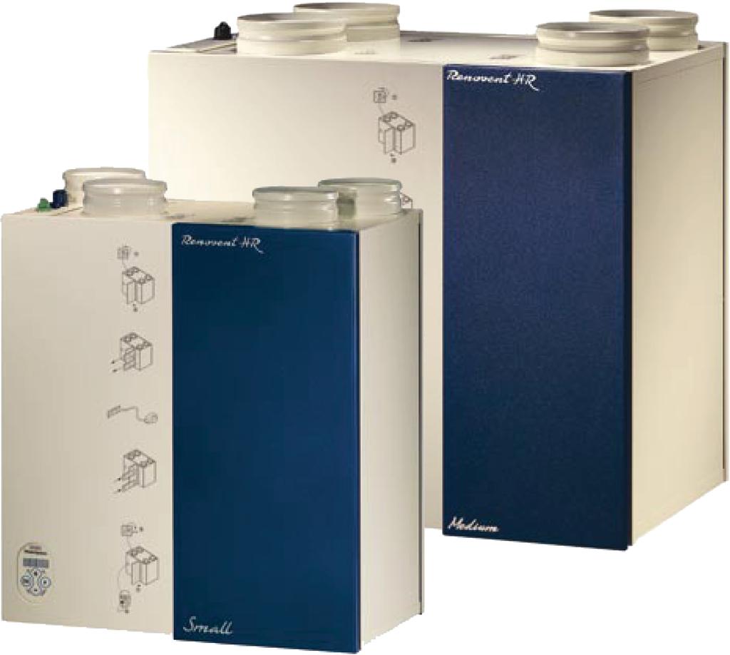
6 Chapter 2 Version The Renovent HR is available in two versions as regards ventilation capacity: Renovent Medium has a ventilation capacity of up to 300 m 3 /h at 150 Pa resistance in the duct system; Renovent Large produces a maximum of 400 m 3 /h at 150 Pa resistance in the duct system. 2.1 Ducts connection options The Renovent HR is available in three versions as regards ducts connections: all connections at the top; type 4/0 to dwelling" at the bottom; type 3/1 to dwelling and from dwelling at the bottom; type 2/2 Both versions are available in various versions as regards bypass unit. The Renovent HR comes ready to plug in with a 230 V mains plug and a connection for the low-voltage multiple switch on the outside of the appliance. For pictures and dimensions of these appliances, see sections to Filter door position options The appliance is available ex factory in a right-hand or lefthand version. That changes the position of the duct connections. on the left-hand side of the appliance. It is possible to convert a right-hand appliance into the left-hand side by reversing the appliance, exchanging front and rear covers and moving the display. Similarly, a left-hand version can be converted into a right-hand one. 2.3 Bypass The appliance can be supplied ex factory with a nearly 100% bypass, which can be used to interrupt the heat recovery, if desired, to supplied fresh, cool outside air. The information and diagram in these installation instructions refer to the 100% bypass that is supplied ex factory; in this version the heat exchanger is equipped with a sliding grate that shuts off the air- supply air is shut off; in the left-hand version the discharge air possible to mount a sliding grate. The operation and preconditions of the bypass control are explained in more detail in section 4.3. The bypass unit that is 2 Renovent HR Medium/Large
7 Version Chapter Technical information Renovent HR Medium Renovent HR Large Supply voltage [V~/Hz] 230/50 Protection degree IP31 Dimensions (w x h x d) [mm] 675 x 602 x x 602 x 430 Duct diameter [mm] Ø160 Ø180 External diameter condensate discharge [mm] Ø20 Massa [kg] (Excl. bypass unit of 3.5 kg) Filter class G3 (F6 optional) Fan setting Ventilation capacity [m 3 /h respectively] Permissible resistance ducts system [Pa] Rated power [W] Rated current [A] Static pressure [Pa] Noise capacity level Lw (A) Housing emission [db(a)] < Duct from dwelling [db(a)] < < Duct to dwelling bypass unit Supply voltage [V/Hz] 230/50 Protection degree IP31 Dimensions (w x h x d) [mm] 675 x 602 x 85 Weight [ kg] 3.5 Rated power [W] 0.5 Rated current [A] 0.02 Renovent HR Medium/Large 3
8 Chapter 2 Version 2.5 Fan graphs Flow rate [m 3 /h respectively] Fan graph Renovent HR Medium 5677-A Note: The value stated in the circle is the capacity per fan (in Watt) Resistance ducts system [Pa] Resistance ducts system [Pa] Flow rate [m 3 /h respectively] Fan graph Renovent HR Large 5678-A Note: The value stated in the circle is the capacity per fan (in Watt) 4 Renovent HR Medium/Large
9 Design Chapter Exploded view appliance Function components 1 Interior temperature sensor Measures the temperature of the air from the dwelling. 2 Heat exchanger Ensures heat transfer between input and output air 3 Filters 4 Atmospheric temperature sensor Measures outside air temperature. 5 Communication port 6 Metric swivel Swivel for feeding through power cable 230 Volt 7 OpenTherm connection Two-pole connector for OpenTherm control 8 Option pcb (non-standard) Contains various additional control inputs and outputs for provisions such as a preheater, a postheater, two control valves, CO 2 sensor, H 2 O sensor and emergency setting. 9 Input fan Feeds fresh air into the dwelling. 10 Basic pcb Contains the control electronics for the basic functions. 11 Computer port Computer connection for service purposes. 12 Control panel Interface between user and control electronics. 13 Output fan Discharges fouled air from the dwelling to the atmosphere. 14 Duct spigots Connections for the input and output ducts. 15 Connection condensate discharge Connection condensate discharge. Renovent HR Medium/Large 5
10 Chapter 4 Operation 4.1 Outline description An appliance from the Renovent HR series is a highly advanced heat recovery unit, specially designed for minimum energy consumption and maximum comfort. This is achieved with the aid of various electronic control systems. A control unit with microprocessor controls and monitors the safe operation of the appliance and ensures that the air quantities remain constant and at the preset values. The Renovent HR comes with an control panel with display, enabling stepless adjustment of the volume without having to open the appliance. Moreover, information regarding the operation can be read out from the outside of the appliance. 4.2 LED display system and control panel be used to retrieve and modify the settings in the control unit program. The control panel has four keys and a display Example: The display now shows that the appliance is running at venti- 280 m 3 /h. Control panel Renovent HR The 4 keys have the following functions: F Function key / switching on and off parameter menu + Next parameter / increase value - Previous parameter / decrease value OK Switching on and off settings menu / manual 1 = Display 3 = Key increase parameter 4 = Function key 5 = Key reduce parameter On the left the display indicates the ventilation setting or the parameter type. On the right it shows the readout value, for instance the preset volume. Other commands can be entered with key combinations. F & - (reset), parameter value back to factory setting OK & + (ON),O switch on appliance OK & - (OFF),F switch off appliance Wherever this booklet states that a key has to be pressed, the key in question is printed in quotation marks and in bold. Example: - press key OK. 4.3 Bypass conditions The bypass, if mounted, makes it possible to supply fresh outside air that is not heated by the heat exchanger. Particularly during summer nights it is desirable to supply cooler outside air. Then the hot air in the dwelling is replaced by cooler outside air in so far as possible. The bypass damper opens when the interior temperature exceeds an adjustable temperature (standard 22 C) while the outside air is warmer than an adjustable temperature (standard 10 C) but colder than the interior air. Out- air quality is optimal, irrespective of the bypass setting. The installer can set the bypass for different situations at adjustable parameter I8 (also see 6.4). 6 Renovent HR Medium/Large
11 Operation Chapter Frost safety The frost protection system ensures that the secondary side of the heat exchanger (outlet side) does not freeze up by in- dependent on the outside air temperature and the pressure across the heat exchanger. 4.5 Filter indication mation refer to sections 7.2 and Option pcb The Renovent HR appliance can be equipped with an option pcb (article code ). It provides the following functions. Input 0-10 V for a carbon dioxide sensor When several people are present in the dwelling, more C0 2 is produced and then this sensor automatically increases the ventilation quantity. Input 0-10 V for a moisture sensor When the moisture content in the dwelling increases, for instance when someone is taking a shower, this sensor automatically increases the ventilation quantity. Switching input for bedroom valve. With this input (make contact) the bedroom valve can be controlled, for instance using a time switch. Switching output for bedroom valve 24 VAC The option pcb has a built-in control for a 24 VAC bedroom valve. Such a valve can directly be connected to the pcb. The valve can be controlled from the switching input for the bedroom valve. If it is recommended to combine the discharge of the central heating and the Renovent HR appliance, the Renovent con- safety valve. The valve can directly be connected to this pcb Control for preheater up to 1000 W The preheater ensures that the input air is kept above 0 C, so the Renovent HR can continue the balanced ventilation also at very low atmospheric temperatures. The option pcb contains a control for a preheater up to 1000 W. The preheater can be connected to the option pcb without separate control. The hook-up wire of the preheater must be fed into the appliance; the 230 V power cable must separately be connected to the option pcb. Control for postheater up to 1000 W The postheater ensures that the supply air that is blown into the dwelling can be kept at the preset temperature. That way additional warmth can be brought into the dwelling. The option pcb contains a control for a postheater up to 1000 W. The postheater can be connected to the option pcb without separate control. The hook-up wire of the postheater must be fed into the appliance; the 230 V power cable must separately be connected to the option pcb. Two freely programmable make contact inputs These inputs make it possible : to open the bypass without regard for the temperature conditions; to switch the inlet or outlet low or high, to circumvent the frost protection; to switch the inlet low when the bypass opens. Switch input for emergency. emergency mode. As standard that is set to switch off the fans. Renovent HR Medium/Large 7
12 Chapter 5 Installation 5.1 Installation general The appliance installation procedure can be summarised as follows: 1. Placing the appliance ( 5.2) 2. Connecting the ducts ( 5.3) 3. Connecting the condensate discharge ( 5.4) 4. Electric connection: Connecting the multiple switch and, if necessary, the mains power and the OpenTherm connector ( 5.5) The Renovent HR must be installed in accordance with: Quality requirements ventilation systems dwellings, Quality requirements balanced ventilation in dwellings, The regulations for ventilation of dwellings and residential buildings The safety regulations for low-voltage installations, The regulations for connection to interior sewers in dwellings and residential buildings, Any additional regulations of the local utilities The installation instructions for the Renovent HR. 5.2 Placing the appliance An appliance from the Renovent HR series can directly be mounted to the wall using the suspension strips supplied for that purpose. For a vibration-free result the appliance must be mounted to a solid wall with a minimum mass of 200 kg/m 2.A measures such as double panelling or extra studs are required. (article code ). In addition, the following aspects must be taken into account. The appliance must be placed level. The installation room must be such that a good condensate discharge with air trap and pitch for condensate can be made. The installation room must be frost-free. Make sure there is a free space of at least 70 cm at the front of the appliance and a free headroom of 1.8 m 1.8 m. 5.3 Connecting ducts valve. The appliance itself controls the air quantities. To prevent condensation on the outside of the outside air input duct and the air output duct from the Renovent HR, these ducts must externally be provided with a vapour barrier as far as the appliance. If Brink synthetic (EPE) pipe is used here, additional insulation is not necessary. Use Brink thermally insulated hoses for deviating diameters. For optimum fan noise damping, it is recommended to use Brink acoustic hoses with a length of 1 metre (Medium version) between the appliance and the ducts from and to the dwelling. 1.5 metre (Large version). Pay attention to crosstalk and installation noise, also for incorporated ducts. Design the duct with separate branches to the damper to prevent crosstalk. If necessary, the input ducts must be insulated, for instance when they are installed outside the insulated envelope. Preferably use Brink incorporated ducts. These ducts have been developed with a view to a low duct resistance. A minimum duct resistance of 160 mm recommended for the Renovent Medium. A diameter of 180 mm is recommended for the Renovent Large. The duct must always have an adequate diameter, that is a diameter of Ø150 mm for air quantities up to 250 m 3 /h, a diameter of Ø160 mm for air quantities up to 325 m 3 /h and a diameter of Ø180 mm for air quantities up to 400 m 3 /h. The duct spigots of the Reno- loose sealing rings ø160 mm. The duct spigots of the Reno- eccentric adapters of ø180 mm. The centre of the connecting duct can be shifted by rotating these eccentric adapters Renovent HR Medium/Large
13 Installation Chapter A 1 = Renovent HR (place level) 2 = Recommended inlet air suction 3 = Input air suction through the roof area 4 = Input air suction under the tiles 5a = Free suction bottom roof area 5b = Free suction top roof area 6 = Sewer relief 7 = Recommended location ventilation air output; use Brink insulated sleeve. recovery pipe 9 = Condensate discharge 10 = Acoustic hose 11 = Ducts from and to dwelling Arrange the exterior air supply from the shadowed side of the dwelling, for instance from the wall or overhang. If the outdoor air is sucked in from under the tiles, it must be ensured that no condensation develops in the roof boarding and no water can run in. Ventilation air can be sucked in from under the tiles if air can access freely at the top and the bottom of the roof area and the sewage vent stack does not end under the tiles. This solution is not recommended for the Renovent with bypass. Always use an insulated ventilation roof sleeve. The maximum permissible resistance in the duct system is 150 Pa at the maximum ventilation capacity. If the resistance of the duct system is higher, the maximum ventilation capacity will be lower. The location of the mechanical ventilation output and the sewer stack vent relative to the input must be chosen to prevent nuisance. Choose the location of the input valves to prevent fouling and draught. We recommend the use the Brink weak-inductive input dampers A = Spacing 10 mm above roof deck B = Roof insulation C = Seal with foam D = Pipe for make-up air to be carefully insulated and provided with vapour barrier Feed the output duct through the roof boarding in such a manner that no condensation develops in the roof boarding. Install the output duct between the Renovent HR and the roof sleeve in such a manner that surface condensation is prevented. 1 = Brink low-inductive supply valves 2 = Input from wall 3 = Suction valve in ceiling or high in wall 4 = Prevent crosstalk 5 = Preferably Brink incorporated ducts a = Gap under the door 2 cm A Renovent HR Medium/Large 9
14 Chapter 5 Installation 5.4 Connecting the condensate discharge The condensate discharge line for the Brink Renovent HR is fed through the lower panel. The condensate must be discharged through a drainpipe. The drain must discharge under the water level in the U-trap. The condensate discharge comes separately with the appliance and the installer must screw it into the underside of the appliance. This condensate discharge connection has an external connecting diameter of 20 mm. The condensate discharge line can be glued to it, if necessary using a square bend. The installer can glue the condensate discharge in the desired position in the lower part of the appliance. See the drawing below for an example of a connection to a drainpipe. Pour water into the drip tray to create an air trap Electric connections The appliance comes with a 230 V mains plug Connecting the multiple switch The multiple switch (not supplied with the appliance) is connected to the modular connector type RJ12 that is placed at the top cases requires an RJ11 plug in combination with a 4-core modular cable. Dependent on the type of multiple switch that is used, a plug RJ11 or RJ12 can be connected to it. ses requires an RJ12 plug in combination with a 6-core modular cable. Refer to the next page for examples of wiring diagrams. Connector B is a 2-pole screw connector which is used in combination with demand-controlled ventilation A A = Modular connector B = OpenTherm connector 10 Renovent HR Medium/Large
15 Installation Chapter 5 switch, viz.: nector (6-core cable, two modular connectors RJ12/6), connector (4-core cable, one modular connector RJ11/4 (Note that for both modular connectors the tab must be mounted on the side of the mark on the modular cable) E2075-E The colours of wires C1 - C6, and C1 to C4 respectively, indicated in the diagrams above may vary; that depends on the type of modular cable used. Renovent HR Medium/Large 11
16 Chapter 5 Installation Connecting the OpenTherm connector In combination with demand-controlled ventilation, the appliance can also be controlled with the OpenTherm protocol instead of as low-voltage switch. OpenTherm allows continu- tage cable with a core diameter of at least 0.8 mm must be used as connecting cable. Interchanging the cable connection ce's performance Connecting the power plug The appliance can be connected to an easily accessible, earthed wall socket with the plug that is mounted to the appliance. The electric installation must comply with the requirements of your power company. Warning The fans and control print carry a high voltage. Always take the voltage from the appliance by pulling the mains plug when working on the appliance. 12 Renovent HR Medium/Large
17 Installation Chapter Connections and dimensions Renovent HR Connections Renovent HR Medium right-hand version Renovent HR Medium right-hand 2/ Renovent HR Medium right-hand 4/ I = To dwelling II = To atmosphere III = From dwelling IV = From atmosphere Renovent HR Medium right-hand 3/ A = Top view B = Front view C = Side view D = Bottom view E = Electric connections F = Detail wall mounting (make sure to correctly place the rubber strip, washers and caps) G = Connection condensate discharge Renovent HR Medium/Large 13
18 Chapter 5 Installation Connections Renovent HR Medium left-hand version Renovent HR Medium left-hand 2/ Renovent HR Medium left-hand 4/ I = To dwelling II = To atmosphere III = From dwelling IV = From atmosphere Renovent HR Medium left-hand 3/ A = Top view B = Front view C = Side view D = Bottom view E = Electric connections F = Detail wall mounting (make sure to correctly place the rubber strip, washers and caps) G = Connection condensate discharge 14 Renovent HR Medium/Large
19 Installation Chapter Connections Renovent HR Large right-hand version Renovent HR Large right-hand 2/ Renovent HR Large right-hand 4/ I = To dwelling II = To atmosphere III = From dwelling IV = From atmosphere Renovent HR Large right-hand 3/ A = Top view B = Front view C = Side view D = Bottom view E = Electric connections F = Detail wall mounting (make sure to correctly place the rubber strip, washers and caps) G = Connection condensate discharge Renovent HR Medium/Large 15
20 Chapter 5 Installation Connections Renovent HR Large left-hand version Renovent HR Large left-hand 2/ Renovent HR Large left-hand 4/ I = To dwelling II = To atmosphere III = From dwelling IV = From atmosphere Renovent HR Large left-hand 3/ A = Top view B = Front view C = Side view D = Bottom view E = Electric connections F = Detail wall mounting (make sure to correctly place the rubber strip, washers and caps) G = Connection condensate discharge 16 Renovent HR Medium/Large
21 Putting into operation Chapter Switching the appliance on and off There are two methods to switch the appliance on or off. 1. Through software; the appliance remains connected to the mains, when switching off bu software only the fans are stopped. 2. Removing the mains plug or inserting it into the wall socket; the voltage is taken from the appliance. Switching on Mains power: connect the mains plug to the electric installation Through software; simultaneously press keys OK and + to switch on the appliance through software (Only possible after the appliance has been switched off through software.) 6.2 Setting the air quantity The air quantity of the Renovent HR Medium/Large for settings 1, 2 and 2 have been adjusted in the factory at 100, /150/200 and 225/300 m 3 /h. The performance of the Renovent depends stance. Important: Setting 1: must always be lower than setting 2. Setting 2: must always be lower than setting 3; Setting 3: adjustable between 50 and 300/400 m 3 /h; If these conditions are not complied with, the air quantity of the higher setting will automatically be adjusted. here the air quantity for setting 3 will be changed from 300 to 280 m 3 /h): 1. Press key F during 3 seconds to call up the settings menu. tes the position of the 3-way switch. >3s >3s Switching off Through software; simultaneously press keys OK and - to switch on the appliance through software. The text OFF appears on the display. Mains power: pull the mains plug from the mains to take the voltage from the appliance. >3s 2. Use key + to select the desired parameter (U1 = setting 1: 1, U2 = setting 2: 2, U3 = setting 3; U4, U5 and U8 only apply when a bypass unit is used). 3. Press key OK during 1 second to read the selected parameter value NOTE! When working on the appliance, always take the voltage and subsequently pulling the mains plug. 4. The keys + or - can be used to modify the selected parameter value. Renovent HR Medium/Large 17
22 Chapter 6 Putting into operation A saved and stored; B removed; C put back to factory setting. A Simultaneously press keys F and + F than + ) to store - - value. Press key OK to go back to the settings menu; if required, several settings can now be sive). Now continue with item 6. C Simultaneously press keys F and - to go back to the factory setting. The factory setting will The factory setting remains on the display. Press key OK to go back to the settings menu; if required, several settings can now be sive). Now continue with item Press key F during 1 second to leave the settings menu. B Press key OK to go back to the settings menu without sa- previous setting will be maintained. If required, several set- item 2 to 5 inclusive). Now continue with item Other user settings In addition to the air quantities per setting, the user can also adjust the following parameters. U4. Minimum atmospheric temperature bypass. This is the minimum atmospheric temperature at which the bypass conditions. U5. Minimum indoor temperature for the bypass. This is the minimum indoor temperature at which the bypass opens, ditions. U8 Not applicable These setting possibilities are only relevant if the appliance is equipped with a bypass. These bypass settings are made in the same manner as described in section 6.2. Refer to the table in section for the factory settings. 18 Renovent HR Medium/Large
23 Putting into operation Chapter Installer settings ration of the appliance, these have been placed in a separate installer parameters set. Consequently, these parameters can plained in section I1. Fixed imbalance. This can be used to keep the pressure in the dwelling at a higher (+) or lower (-) level than the atmospheric pressure. Positive imbalance (+): the output fan ventilates the set value in [m 3 /h] less than the input fan. Negative imbalance (-): the input fan ventilates the set value in [m 3 /h less than the output fan. I2. No contact step 11 This setting determines the ventilation position when no switch contact is connected to position 1; the appliance will start running at the ventilation position set here. I3. Not applicable. I4. Switch line 1 step. Determines what position of the multiple switch matches line 1 on the control unit. I5. Switch line 2 step. Determines what position of the multiple switch matches line 2 on the control unit. I6. Switch line 3 step. Determines what position of the multiple switch matches line 3 on the control unit.n 7. Imbalance permissible? This determines whether for instance the frost protection may affect the imbalance.mo I8 Bypass mode. There is a choice between 3 situations Mode 0 Mode 1 (standard setting) Mode 2 The bypass valve is not operated The bypass valve - if installed - is opened when the temperature conditions are complied with The inlet fan starts running at the lowest possible rpm if the temperature conditions are complied with I9. Hysteresis bypass. Here it can be entered how much the indoor temperature may drop before the bypass closes or the inlet fan starts running at the normal rpm. I10. Constant pressure switched off. Here it can be set whether in all cases the fans are running sure when a certain resistance is exceeded. I11. Preheater or postheater. This indicates whether a preheater or postheater is connected is. Setting I11 I12. Temperature preheater. This sets the offset temperature preheater. I13 Filter message. and the LED of the 3-way switch. I14 Presence option pcb. This indicates whether an option pcb is mounted. Option setting when heat recovery is used in combination with central heating; only heat recovery or the combination central heating + heat recovery. Only heat recovery = 0; Central heating + heat recovery = 1 I16 Fan setting for central heating + heat recovery Fan(s) off for central heating + heat recovery (only applicable if I15 = 1). Setting I16 Situation 0 No preheater or postheater 1 Preheater connected to basic pcb 2 & 3 Only use this setting for option pcb Situation fan(s) 1 Output fan off 2 Input fan off 3 Both fans off I17 Repeat time in hours for switching off the fan(s) selected under I16 for central heating + heat recovery. I18 Maximum switch-off time in seconds for the fan(s) selected under I16 for central heating + heat recovery. I19 Minimum switch-off time in seconds for the fan(s) selected under I16 after switching on 230V for central heating + heat recovery. Refer to the table in section for the factory setting Renovent HR Medium/Large 19
24 Chapter 6 Putting into operation 6.5 Menu structure display The menu structure is divided into a readout section and a settings section. The number of visible parameters depends on the parameter set. The user has the parameter set "user"; a more comprehensive readout programme is available for the installer. It can be activated by simultaneously pressing keys F and OK during 3 seconds Diagram menu structure Operating condition Press key OK and - > second Switching off the appliance Press key OK and + > second Switching on the appliance READOUT SECTION Press OK key Press OK key Press + and - key Reset fault Display user data - If no key is operated during 5 minutes Press + or - key Press OK and F - key > 3 seconds Readout menu installer Press + or - key Display installer data. - If no key is operated during 5 minutes Press F - key > 3 seconds Settings menu User Installer - Press key F > 1 second - If no key is operated during 5 minutes - Press key F and OK > 3 seconds Press + or - key Activate parameter set installer Press + or - - SETTINGS SECTION - Press key OK > 1 second - If no key is operated during 1 minute Select parameters: - standard U1 - U8 - with option pcb (n.a.) U1 - U8 Press OK > 1 second to display the selected parameter setting Select parameters: - standard U1 - U8 I1 - I14 - with option pcb U1 - U8 (n.a.) I1 - I19 P1 - P17 Press OK > 1 second to display the selected parameters - Press key OK > 1 second - If no key is operated during 1 minute Press keys + or - Press key + or - - Restore all Factory settings Press key F - If no key is operated during 1 minute Modify selected setting Modify selected setting - If no key is operated during 1 minute Press key F Press key F or + - Press key F or + > 1 second Press key F Factory setting Press key F or - - Press key F or - > 1 second Factory setting Do not save Press key OK - Press key OK > 1 second Do not save Renovent HR Medium/Large
25 Putting into operation Chapter Readouts settings As standard the current position of the multiple switch and the connected output volume are shown (Operational mode). On the left the position of the multiple switch (position 1, 2 or 3) is shown and to the right of the dot the volume of the output fan is shown. a = Setting the multiple switch b = Volume output fan Reading out settings by the user The user can read out other relevant data using keys "+ and - (step 0 to step 6). Step numbers are not shown on the display! See the table of section for user readout; when no key is operated during 5 minutes, the display automatically returns to operational mode. Key + can be used to scroll through the menu; key - always takes you back to step 0. Modifying settings is not possible in this situation Reading out settings by the installer A more comprehensive readout programme is available for the installer. Pressing keys F and OK during 3 seconds calls up all installer data. In this menu the values cannot Activating this menu always calls up step no. 7 (see table below); pressing key "+" calls up the installer and user data and pressing key "-" takes you back to step no. 1. After 5 minutes this menu automatically disappears and the display will show the operational situation again. In the event of an error, the error code appears on the display; see also chapter 7. >3s Step number Readout (example) Description Remark installer User No.1 2,200 Current position/outlet volume [m 3 /h] No.2 C 0 Message code operating condition C0 = No message C3 = The input fan runs in constant pressure mode C6 = The output fan runs in constant pressure mode No.3 bp.1 Bypass status (only if mounted) 0 = bypass valve shut, 1 = bypass valve automatic 2 = input at minimum No.4 tp.9 Temperature from atmosphere [ C] At negative temperature (below 0 C) then readout tp.9. No.5 ts.21 Temperature from indoors [ C] No.6 In.0 n.a. No.7 u.156 Current input volume [m 3 /h] No U Current output volume [m3 /h] No.9 t.180 Current pressure input duct [Pa] No.10 A.180 Current pressure output duct [Pa] No.11 u0.0 Status frost protection 0 = none, 1-4 = imbalance, 5 = input fan off No.12 St.9 Temperature to atmosphere [ C] If not connected St.75 (Sensor not connected as standard) No.13 Pt.18 Temperature to indoors [ C] If not connected Pt.75 (Sensor not connected as standard) Renovent HR Medium/Large 21
26 Chapter 6 Putting into operation 6.7 Modifying settings Modifying settings by the user The user can modify a limited number of settings, that is U1 to U8 inc. (see table section 6.7.3); how to modify these settings Modifying settings by the installer The installer can modify more settings. When parameters are set incorrectly, the appliance can no longer perform up to Also refer to the diagram menu structure section The following actions are required to modify the settings from operational mode: (By way of example parameter 18 (bypass mode) is changed from 1 to 2.) 1 Press key F during 3 seconds to activate the settings menu. 2 Press key F and key OK during 3 seconds to activate the comprehensive installer parameters set. 3 The desired parameter can be found with the aid of keys + and -. (See table section 6.7.3) 4 Pressing key OK calls up this setting. >3s >3s is described in detail in section 6.2 and is also shown in the diagram menu structure of section 6.5. A be saved and stored B be removed; C be restored to factory setting. A Simultaneously press keys F and + setting; this value now blinks 3x red; the value remains on the display. Press key OK to return to the settings menu; if required, other (step 2 - step 5) Continue with step 7. B Press key OK to go back to the settings menu without sa- previous setting will be maintained. Continue with step 7. C Simultaneously press keys F and - F and then - ) to go back to the factory setting. The factory setting will blink 3 times and remain at that value. been removed. Press key OK to return to the settings menu. Continue with step 7. 5 Use keys + and - to modify the value. 7 Press key F during 1 second to leave the settings menu Renovent HR Medium/Large
27 Putting into operation Chapter Adjustable settings table De user-adjustable parameters are indicated with U ; the installer-adjustable parameters are indicated with I (basic pcb) or P (option pcb). Adjustable parameter Description Setting range Factory setting U 1 Volume step (max-10) 100 U 2 Volume step (max-5) Medium 150 Large 200 U 3 Volume step (Medium) (Large) 225 Medium 300 Large User U 4 Minimum atmospheric temperature bypass U 5 Minimum indoor temperature bypass U 8 Not applicable (off) I 1 Fixed imbalance I 2 No contact step 0,1,2,3 1 I 3 Not applicable I 4 Switch line 1 step 0,1,2,3 1 I 5 Switch line 2 step 0,1,2,3 2 I 6 Switch line 3 step 0,1,2,3 3 I 7 Imbalance permissible (Yes) I 8 Bypass mode 0,1,2 1 I 9 Hysteresis bypass I10 Constant pressure switched off (no) I11 Preheater or postheater 0, 1, 2, 3 0 I12 Offset temperature preheater I13 Filter message on/off (on) I14 Option pcb present (no) I (heat recovery) I16 Fan off 1,2,3 1 (Output fan) I17 Repeat time (hours) installer I18 Minimum switch-off time fan(s) (seconds) I19 Minimum switch-off time fan(s) after switching on 230V (second) For a description of these settings refer to section 6.2 and 6.3 for U1 - U8 and section 6.4 for I1 - I19. The description of parameters P1 - P17 that may be displayed are included in the installation instructions that come with the option pcb. Renovent HR Medium/Large 23
28 Chapter 7 Fault 7.1 Trouble shooting If the control system detects an error, this is shown on the display by means of a number, preceded by a letter F (Failure). If 3-way switch will also start blinking. The examples shown here is the error F9.; this means something is wrong with the wiring to the atmospheric temperature sensor or with the sensor itself. The appliance remains in this error mode until the problem in question has been solved. Then the appliance will reset itself (auto reset) and the display will once more show operational mode. The table to section 7.3 gives an overview of the errors, possible causes and the actions to be undertaken. 7.2 Filter indication If the display shows the message " FIL then this means the tion has been mounted (= option), then simultaneously with this message on the display, the LED on the switch will light up. OK The text FIL will blink for a moment and then the display will return to operational mode Renovent HR Medium/Large
29 Fault Chapter Display codes Table fault codes Fault code Cause Action user Action installer F2 The inlet fan has stopped. Contact the installer. Replace the inlet fan; it is defective. F5 The outlet fan has stopped. Contact the installer. Replace the outlet fan; it is defective. F9 The temperature sensor that measures the temperature of the input air is defective. The appliance operates as expected, but the bypass is out of operation. Contact the installer. Check the wiring from the sensor to the basic pcb. Check the sensor connection to the wiring. Replace the sensor. F10 The temperature sensor that measures the temperature of the output air is defective. The appliance operates as expected, but the bypass is out of operation. Contact the installer. Check the wiring from the sensor to the basic pcb. Check the sensor connection to the wiring. Replace the sensor. Note! If setting 2 does not work with a mechanical rpm control device such as a multiple switch, the RJ connector has been connected the wrong way round. Cut off one of the RJ connectors to the rpm control and mount a new connector the other way round. Renovent HR Medium/Large 25
30 Chapter 8 Maintenance 8.1 User maintenance User maintenance is limited to periodically cleaning or repla- indicated on the display (it shows the text " FIL ) or, if a multiple 1 Put the 3-way switch at setting 1 to let the appliance s fans out. Without bypass unit With bypass unit indication must be reset by pressing key OK during 1 second. has been reset. The appliance will return to operational mode Put the 3-way switch back to the original setting. taken out. Without bypass unit With bypass unit 5387-B 26 Renovent HR Medium/Large
31 Maintenance Chapter Installer maintenance Installer maintenance includes cleaning the heat exchanger and fans. Dependent on the conditions, this must done about once every three years. 1 Switch off the appliance on the control panel (simultaneously press keys "OK and - and "-" during 3 seconds) and switch off the power supply. 4 If the appliance is equipped with the optional bypass unit, it must now be removed. First remove the display (see item 7 for appliance without bypass unit) and unscrew the four hexagon socket bolts M6 x 16; pull the connectors and take the bypass unit from the appliance. Only for Renovent HR equipped with the optional bypass unit! 5 Remove the heat exchanger. Be careful not to damage the foam parts in the appliance. Without bypass unit 3 Remove the move the front cover. With bypass unit 6 Clean the heat exchanger using hot water (55 C max.) and a regular detergent. Rinse the exchanger with hot water. remove the valve control device from the sliding grate. Without bypass unit With bypass unit 5388-A Renovent HR Medium/Large 27
32 Chapter 8 Maintenance 7 Remove the control panel. 10 Remove the spiral casing. 11 Clean the fan with a soft brush Make sure the balancing weights do not shift A 12 Place the spiral casing back on the fan unit Pull all connectors from the basic pcb. Take the earth wire from the housing. 13 Place the fan unit back in the appliance. 14 Place the earth wire back and replace the connectors that were pulled. 15 Mount the control panel. 16 Place the heat exchanger back into the appliance. 17 Place the front cover and, if applicable, the bypass unit back. facing the exchanger. 20 Switch on the power supply. 9 Remove the fan unit. 21 Switch off the appliance on the control panel (simultaneously press keys OK and + during 3 seconds) indication must be reset by pressing key OK during second 28 Renovent HR Medium/Large
33 Electric diagrams Chapter Basic diagram without bypass indoor temperature sensor outdoor temperature sensor BASIC PCB RNV-04 input Fan output Fan Preheater OpenTherm connector n.c. Maximum 24V50mA! n.c. control panel n.c. 230 Vac 50 Hz emergency bedroom valve contact P1 contact P2 postheater OPTION PCB RNV-02 preheater postheater bedroomvalve, 24Vac,10 VA 24Vac, 10 VA E Renovent HR Medium/Large 29
34 Chapter 9 Electric diagrams 9.2 Basic diagram with bypass indoor temperature sensor outdoor temperature sensor BASIC PCB RNV-04 input fan output fan preheater OpenTherm connector Maximum 24V50mA! control panel emergency bedroom valve contact P1 contact P2 postheater OPTION PCB RNV-02 pre heater postheater bedroomvalve, 24Vac,10 VA 24Vac, 10 VA E Renovent HR Medium/Large
35 Electric diagrams Chapter Wiring diagram without bypass 1 = Absence mode 2 = Presence mode 3 = Cooking/showering mode C1 = brown C2 = blue C3 = green/yellow C5 = white C9 = red C10 = yellow E a = 3-way switch B = OpenTherm connector C = Interior temperature sensor D = Basic pcb E = Input fan F = Output fan G = Control panel H = Atmospheric temperature sensor J = Option pcb (not mounted as standard) Renovent HR Medium/Large 31
36 Chapter 9 Electric diagrams 9.4 Wiring diagram with bypass 1 = Absence mode 2 = Presence mode 3 = Cooking/showering mode C1 = brown C2 = blue C3 = green/yellow C4 = black C5 = white C6 = no.1 C7 = no.7 C9 = red C10 = yellow C14 = blue/white E A = 3-way switch B = OpenTherm connector C = Interior temperature sensor D = Basic pcb E = Input fan F = Output fan G = Control panel H = Atmospheric temperature sensor J = Option pcb (not mounted as standard) K = Valve control device sliding grate (only for bypass ex factory) L = Valve control device bypass valve (only if bypass is mounted) M = Bypass pcb (not mounted as standard) 32 Renovent HR Medium/Large
37 Electric diagrams Chapter Wiring diagram connection preheater to Renovent HR without option pcb C1 = brown C2 = blue C3 = green/yellow C4 = black E A = Heating coil B = Maximum safety with manual reset C = Connecting plug 230V50Hz D = Cable to be connected by installer L = LED maximum safety; lights up when activated Note! Parameter I11 must be set at 1 when connecting the preheater to the basic pcb! See section 6.4 Renovent HR Medium/Large 33
38 Chapter 10 Service 10.1 Exploded view Renovent HR Medium/ Large When ordering parts, in addition to the article code number (see exploded view), please state the type of the heat recovery appliance, the serial number, the year of production and the name of the part: Example Appliance type : Renovent HR 4/0 R Medium Serial number : Year of construction : 2009 Part : Fan Article code : Quantity : 1 N. B.: Appliance type, serial number and year of production are EX A 10.2 Article codes service parts Renovent HR Medium/Large No. Article description Article code 1 Filter kit (standard version) Filter kit (version with bypass) Fan Medium Fan Large Basic pcb Medium Basic pcb Large Temperature sensor Heat exchanger or Heat exchanger with grid (only for factory-mounted bypass) Control panel with display prior notice. 34 Renovent HR Medium/Large
39 DECLARATION OF CONFORMITY The heat recovery appliances type Renovent HR Medium/Large, manufactured by Brink Climate Systems B.V. in Staphorst, the Netherlands, bear the CE label and satisfy the machine directive 89/392/EEC, the low voltage directive 73/23/EEC, the materials directive ROHS 2002/95/EC and the EMC directive 89/336/EEC. Brink Climate systems B.V. warrants that the Renovent HR Medium/Large heat recovery appliances are manufactured from high-quality materials and that continuous quality control ensures that they comply with the above directives. Brink Climate Systems B.V. W. Hijmissen, Managing director Renovent HR Medium/Large 35
40 Brink Climate Systems Ireland Ltd Unit 5D, Killowen House, Southern Link Business Park, Naas, Co. Kildare Tel: Fax:
Renovent Excellent 180 (Plus)
") Renovent Excellent 180 (Plus) INSTALLATION INSTRUCTIONS (English) WWW.BRINKAIRFORLIFE.NL 614293-D Installation instructions Heat recovery appliance Renovent Excellent 180 (Plus) STORE NEAR THE APPLIANCE
Renovent Excellent 180 (Plus) INSTALLATION INSTRUCTIONS (English) WWW.BRINKAIRFORLIFE.NL 614293-D Installation instructions Heat recovery appliance Renovent Excellent 180 (Plus) STORE NEAR THE APPLIANCE
Renovent Excellent 450 (Plus)
") Renovent Excellent 450 (Plus) INSTALLATION INSTRUCTIONS (English) 614298-B Installation instructions Heat recovery appliance Renovent Excellent 450 (Plus) STORE NEAR THE APPLIANCE This appliance can be
Renovent Excellent 450 (Plus) INSTALLATION INSTRUCTIONS (English) 614298-B Installation instructions Heat recovery appliance Renovent Excellent 450 (Plus) STORE NEAR THE APPLIANCE This appliance can be
Technical Sheet. Heat recovery appliance Renovent Excellent 180 (Plus) Renovent Excellent 180 1
 Renovent Excellent 180 1") Technical Sheet Heat recovery appliance Renovent Excellent 180 (Plus) Renovent Excellent 180 1 Application The Brink Renovent Excellent is a heat recovery ventilation unit with an efficiency of 95%, a
Technical Sheet Heat recovery appliance Renovent Excellent 180 (Plus) Renovent Excellent 180 1 Application The Brink Renovent Excellent is a heat recovery ventilation unit with an efficiency of 95%, a
MRXBOX90S. Mechanical Ventilation with Heat Recovery. Installation and Maintenance
 MRXBOX90S Mechanical Ventilation with Heat Recovery Installation and Maintenance The EMC Directive 2004/08/EC The Low Voltage directive 2006/95/EC.0 Introduction The Nuaire MRXBOX90S is a heat recovery
Renovent Sky 300 (Plus)
") Renovent Sky 300 (Plus) INSTALLATION INSTRUCTIONS (English) WWW.BRINKAIRFORLIFE.NL 612378-E Renovent Sky 300 (Plus) STORE NEAR THE APPLIANCE This appliance can be used by children aged from 8 years and
Renovent Sky 300 (Plus) INSTALLATION INSTRUCTIONS (English) WWW.BRINKAIRFORLIFE.NL 612378-E Renovent Sky 300 (Plus) STORE NEAR THE APPLIANCE This appliance can be used by children aged from 8 years and
That allows for installation of a lowresistance ducts system directly from the appliance. CONSTANT FLOW FANS
 Heat Recovery Units Balanced ventilation brings comfort and health to your home throughout the year. After all, wouldn t you like to always have plenty of clean, fresh air in your home? HRV ensures t hat
Air Comfort. Installation instructions (English) A
 A") Air Comfort Installation instructions (English) WWW.BRINKAIRFORLIFE.NL 614788-A This appliance may be used by children as of 8 years of age, persons of reduced mental or physical capacities and those of
Air Comfort Installation instructions (English) WWW.BRINKAIRFORLIFE.NL 614788-A This appliance may be used by children as of 8 years of age, persons of reduced mental or physical capacities and those of
CI/SfB (57.5) November 2008
 November 2008") CI/SfB (57.5) climate systems November 2008 High-comfort, low-energy ventilation An energy efficient, fresh, clean and healthy climate - all year round Ubbink Heat Recovery Ventilation (HRV) systems provide
CI/SfB (57.5) climate systems November 2008 High-comfort, low-energy ventilation An energy efficient, fresh, clean and healthy climate - all year round Ubbink Heat Recovery Ventilation (HRV) systems provide
Demand ventilation 2.0
 2.0 INSTALLATION INSTRUCTIONS (English) WWW.BRINKAIRFORLIFE.NL 611586-D Installation instructions 2.0 STORE NEAR THE APPLIANCE This appliance may be used by children aged 8 and above, persons with reduced
Technical Sheet. Heat recovery appliance Renovent Excellent 400 (Plus) Renovent Excellent 400 1
 Renovent Excellent 400 1") Technical Sheet Heat recovery appliance Renovent Excellent 400 (Plus) Renovent Excellent 400 1 Application The Brink Renovent Excellent is a ventilation unit with heat recovery with an efficiency of 95%,
Technical Sheet Heat recovery appliance Renovent Excellent 400 (Plus) Renovent Excellent 400 1 Application The Brink Renovent Excellent is a ventilation unit with heat recovery with an efficiency of 95%,
Instructions for the fan motor control system with integrated wiring terminals SILVER C
 Instructions for the fan motor control system with integrated wiring terminals SILVER C 1. General The motor control system is used for controlling the type EC, 0.41-10 kw fan motors in the SILVER C units.
Silencer Preheater unit Electric post-heating unit Water circulated post-heating unit CO 2 sensor %RH sensor Pressure difference switch LON converter
 VALLOX Product Code: 3158400 L 3158410 R SILENCER (OPTIONAL) INSTRUCTIONS FOR USE AND MAINTENANCE WATER CIRCULATED POST-HEATING UNIT (OPTIONAL) ELECTRIC POST-HEATING UNIT (OPTIONAL)) PREHEATER (OPTIONAL)
Installation and Operating Instructions DÜRR Regeneration Unit for X-ray developers XR 24, XR24 II, XR 24 Nova, XR 24 Pro
 Installation and Operating Instructions DÜRR Regeneration Unit for X-ray developers XR 24, XR24 II, XR 24 Nova, XR 24 Pro 2006/01 Content Important Information 1. Notes... 3 1.1 CE - Labeling... 3 1.2
DC Heat Recovery Unit MVHR Wholehouse heat recovery unit
 DC Heat Recovery Unit MVHR Wholehouse heat recovery unit Stock Ref. N DC Heat Recovery Unit MVHR 443423 Installation, Maintenance & Users Instructions PLEASE READ INSTRUCTIONS IN CONJUNCTION WITH ILLUSTRATIONS.
Instructions for the fan motor control system, SILVER C
 Instructions for the fan motor control system, SILVER C 1. General The motor control system is used for controlling the type EC, 0.41-10 kw fan motors in the SILVER C units. The motor control system is
Settings and Maintenance of the CombinAir
 Atmos CombinAir Settings and Maintenance of the CombinAir Issue 13.8.10 Operation and commissioning: The control unit on the front of the CombinAir is used to adjust the settings during commissioning.
Evap WTW INSTALLATION INSTRUCTIONS D
 Evap WTW INSTALLATION INSTRUCTIONS (English) WWW.BRINKAIRFORLIFE.NL 614796-D English (EN) Installation instructions Humidifier for central ventilation with heat recovery KEEP WITH THE PRODUCT This product
Products documentation (REVISION DATE: 03/10/2011) OMFP6010 (60cm PIROLITIC OVEN)
 OMFP6010 (60cm PIROLITIC OVEN)") Products documentation (REVISION DATE: 03/10/2011) OMFP6010 (60cm PIROLITIC OVEN) Ovens Service Manual Models OMFP6010 CONTENTS This document has been published to be used for service only. The contents
Products documentation (REVISION DATE: 03/10/2011) OMFP6010 (60cm PIROLITIC OVEN) Ovens Service Manual Models OMFP6010 CONTENTS This document has been published to be used for service only. The contents
Healthy, comfortable and energy-efficient ventilation
 Healthy, comfortable and energy-efficient ventilation partner Renovent Excellent 180, 300 and 400 Silent and energy-efficient ventilation 300/400 180 Central ventilation The Renovent Excellent is a mechanical
Installation and Operating Manual
 Installation and Operating Manual SR868C6 System Regulator for Solar Thermal Systems Display Panel Illustration Pos. Button on display panel Button description 1 Green lamp Power indication lamp 2 On/Off
Copperad. Copperad Fan Convectors (November 2005 onwards) Installation, Operation and Maintenance Instructions To be retained by the user
 Installation, Operation and Maintenance Instructions To be retained by the user") Copperad Fan Convectors (November 2005 onwards) Installation, Operation and Maintenance Instructions To be retained by the user Copperad QA/IOM/58 Issue 2 1 GENERAL 1.1 GENERAL DESCRIPTION This manual
Copperad Fan Convectors (November 2005 onwards) Installation, Operation and Maintenance Instructions To be retained by the user Copperad QA/IOM/58 Issue 2 1 GENERAL 1.1 GENERAL DESCRIPTION This manual
PELLET BURNER PV 350
 PELLET BURNER PV 350 INSTRUCTION MANUAL v1.1 1 PRODUCT DESCRIPTION...3 2 SAFETY RULES...3 3 WARNINGS...4 4 INSTALLATION INSTRUCTIONS...5 4.1 BOILER REQUIREMENTS...5 4.2 PELLET CONTAINER...6 4.3 INSTALLATION
MRXBOX95B-LOFT. Mechanical Ventilation Unit with Heat Recovery & Summer Bypass for Loft Mounting. Installation and Maintenance
 MRXBOX95B-LOFT Mechanical Ventilation Unit with Heat Recovery & Summer Bypass for Loft Mounting Installation and Maintenance The EMC Directive 2004/108/EC The Low Voltage directive 2006/95/EC 1.0 Introduction
Warnings, Safety Information and Guidance
 EN SR700 SRHRV Fan TP600 Single Room Heat Recovery Ventilation Fan Unit SRC Controller TP590 Single Room Heat Recovery Ventilation Controller Unit Product Installation Manual ventilation systems Warnings,
INSTRUCTIONS OPTICLIMATE PRO3 SPLIT. Please take note of: - High temperature protection on page 9 - Clear alarm history on page 15
 INSTRUCTIONS OPTICLIMATE PRO3 SPLIT Please take note of: - High temperature protection on page 9 - Clear alarm history on page 15 1 Content - Technical data / Specifications 3 - Installation 4 - Electrical
INTEGRA PLUS ABC. 230V~ 50Hz. Stock Ref. N. Installation and Wiring Instructions IPX2
 INTEGRA PLUS Installation and Wiring Instructions Stock Ref. N INTEGRA PLUS 437666 230V~ 50Hz ABC PLEASE READ INSTRUCTIONS IN CONJUNCTION WITH ILLUSTRATIONS. PLEASE SAVE THESE INSTRUCTIONS. IPX2 VENT-AXIA
CASSETTE UNIT. Comfort Circle
 CASSETTE UNIT Comfort Circle Comfort Circle cassette unit All-round comfort With today's energy prices, building owners are increasingly aware of the need for an efficient climate system to heat or cool
PRODUCT DATA COMFORT 5000 BY NILAN. Ventilation & passive heat recovery. Passive heat recovery. < 5300 m 3 /h
 PRODUCT DATA COMFORT 5000 BY NILAN Ventilation & passive heat recovery Commercial Passive heat recovery Ventilation < 5300 m 3 /h COMFORT 5000 The Comfort 5000 is a ventilation unit suitable for central
OPERATING MANUAL Enertronic Control System 2
 OPERATING MANUAL Enertronic Control System 2 The integrated control system for Lennox chillers in the Ecologic and Seconscrew ranges Manufacturer Lennox Benelux B.V. Postbus 1028, 3860 BA NIJKERK Watergoorweg
FWC860 Wine Cooler Installation, Use and Maintenance
 FWC860 Wine Cooler Installation, Use and Maintenance Customer Care Department The Group Ltd. Harby Road Langar Nottinghamshire NG13 9HY T : 01949 862 012 F : 01949 862 003 E : customer.care@cda.eu W :
FLEXIT S4 X/TT - A4 X/TT S7 X/TT - A7 X/TT
 94108E-06 2005-10 FLEXIT S4 X/TT - A4 X/TT S7 X/TT - A7 X/TT User Manual Air Handling Unit Cabinet Models with Heat Recovery Contents 1 Important Safety Instructions...3 2 Method of Operation - System...3
Xcell 270 Longlife DC wholehouse heat recovery unit
 Xcell 270 Longlife DC wholehouse heat recovery unit Installation and maintenance instructions Xpelair Xcell 270 Longlife DC wholehouse heat recovery unit Xcell 270, Xcell 270BP Please leave this leaflet
JS. Bosch Remote Control
 6720606990-00.1JS Bosch Remote Control For: GWH 635 ES/635 ESO/250SX/250SXO/2400E /2400EO/2400ES/2700ES/715ES/C800ES/C920ES /C920ESC/EVOLUTION 500/INTEGRA 500/C1210ES /C1210ESC/C1050ES/C950ES/940ES/940ESO/830ES
MiLAB Oxygen Control MANUAL & INSTALLATION. MOC-100 Ver 3.0
 MiLAB Oxygen Control MANUAL & INSTALLATION MOC-100 Ver 3.0 Contents 1 INTRODUCTION...3 2 FUNCTIONS...4 2.1 O 2 REGULATION...4 2.2 DISPLAY BOARD...4 2.3 COMMUNICATION THROUGH PANEL...5 2.3.1 Set parameters...5
PRODUCT DATA COMFORT 450 BY NILAN. Ventilation & passive heat recovery. Passive heat recovery. < 450 m 3 /h
 PRODUCT DATA COMFORT 40 BY NILAN Ventilation & passive heat recovery Domestic Passive heat recovery Ventilation < 40 m /h COMFORT 40 Product description The Comfort 40 is an energy-efficient ventilation
FLUEBOOST. flueboost 350 gas fire model
 350 FLUEBOOST flueboost 350 gas fire model The flueboost is a box shaped unit with in line spigots for the flue connection, a pressure switch to ensure safe operation and plug-in electrical fittings for
User Manual. Dryer Controller M720
 User Manual Dryer Controller M720 Hardware version 1.00 Software version 1.00 Preliminary version Manual M720 Dryer controller Page 1 of 42 Document history Preliminary version: - Created in April, 2009
MODEL: DV72 R & L. Mechanical Ventilation with Heat Recovery Installation Instructions and User Manual
 90000556/90000557 Issue 10 9/17 MODEL: DV72 R & L Mechanical Ventilation with Heat Recovery Installation Instructions and User Manual Commissioning Data: to be completed by the installer Date of installation:
MRXBOX95-LH1/LH2. Mechanical Ventilation Unit with Heat Recovery for Loft Mounting Installation and Maintenance. Spigot 4.
 MRXBOX95-LH1/LH2 Mechanical Ventilation Unit with Heat Recovery for Loft Mounting Installation and Maintenance The EMC Directive 2004/108/EC The Low Voltage Directive 2006/95/EC 1.0 Introduction Unit must
GB User and maintenance manual
 GB User and maintenance manual IMPORTANT SAFETY INSTRUCTIONS These instructions shall also be available on website: docs.whirlpool.eu. YOUR SAFETY AND THAT OF OTHERS IS VERY IMPORTANT This manual and
Drying Cabinet Installation and Operating Manual
 Drying Cabinet Installation and Operating Manual Model:- ECO Dryer 2.0 HP Heat Pump Technology CONTENTS THIS USER MANUAL 3 DATA PLATE DETAILS 3 ADVICE ON SAFE OPERATION 3 DESCRIPTION OF THE CABINET 4 AIR
Purge Ventilation Unit. Product Manual. ventilation systems TP625
 EN Purge Ventilation Unit TP625 Product Manual ventilation systems Warnings, Safety Information and Guidance Important Information Important: read these instructions fully before the installation of this
MWS5. Miniature Microwave Presence Detector (standalone) Product Guide. Overview. Features
 Product Guide. Overview. Features") Product Guide MWS5 Miniature Microwave Presence Detector (standalone) Overview The MWS5 series of miniature microwave presence detectors provide automatic control of lighting loads with optional manual
Product Guide MWS5 Miniature Microwave Presence Detector (standalone) Overview The MWS5 series of miniature microwave presence detectors provide automatic control of lighting loads with optional manual
QAF63.2 QAF63.6. Frost sensors for use on the air side. Building Technologies HVAC Products
 1 821 1821P01 Frost sensors for use on the air side Active capillary tube sensor for measuring the lowest temperature within a range of 0 15 C Operating voltage AC 24 V Signal output DC 0...10 V Use On
Oakton TEMP 9500 Advanced Multiparameter Controller
 Oakton TEMP 9500 Advanced Multiparameter Controller Models: 89800-03 & 89800-04 Oakton Instruments 625 E Bunker Ct. Vernon Hills, IL 60061, USA 1-888-4OAKTON (1-888-462-5866) info@4oakton.com Contents
OPERATING MANUAL Enertronic Control System 2
 OPERATING MANUAL Enertronic Control System 2 The integrated control system for Lennox chillers in the Ecologic range Manufacturer: Lennox Benelux B.V. Postbus 1028, 3860 BA NIJKERK Watergoorweg 87, 3861
Tempest TP420/180 Electric Pressure Washer
 Please dispose of packaging for the product in a responsible manner. It is suitable for recycling. Help to protect the environment, take the packaging to the local amenity tip and place into the appropriate
Installation and maintenance instructions for cabin units type vertical IDAC (V50)
") GB Installation and maintenance instructions for cabin units type vertical IDAC (V50). Application. Bundled parts. Handling. Marking. Weight. Transport. Storage 5. Installation 5. Mounting 5. Water trap
GB Installation and maintenance instructions for cabin units type vertical IDAC (V50). Application. Bundled parts. Handling. Marking. Weight. Transport. Storage 5. Installation 5. Mounting 5. Water trap
Advance Optima Module Magnos 17
 Advance Optima Module Magnos 17 Service Manual 43/24-1002-0 EN Table of Contents Page Chapter 1: Description of functions 1-1 Chapter 2: Module variants and components 2-1 Chapter 3: Analyzer variants
USER MANUAL AND TECHNICAL MANUAL
 USER MANUAL AND TECHNICAL MANUAL Kanmed Universal Warming Cabinets Kanmed Blanket Warming Cabinets Kanmed Combination Cabinet GE-2300-070 / 4 2014-05-12 NOTE: This manual contains important information
ROOM-BY-ROOM DEMAND CONTROLLED HEAT RECOVERY VENTILATION
 ROOM-BY-ROOM DEMAND CONTROLLED HEAT RECOVERY VENTILATION 2 AERECO Room-by-room demand controlled heat recovery ventilation REVOLUTION IN THE WORLD OF HEAT RECOVERY VENTILATION Through its new ventilation
Atmos EasySolar. Installation Instructions for. Sloping roof and flat roof installation with evacuated tube collector
 Atmos EasySolar Installation Instructions for Atmos EasySolar Sloping roof and flat roof installation with evacuated tube collector Atmos Heating Systems TBS Building Supplies Ltd Hackwood Road Daventry
PowerVent. Installation manual (GB) English. Store this document in a safe place UK
 English. Store this document in a safe place UK") PowerVent Installation manual (GB) Store this document in a safe place 959.034.03.UK GB Contents Blz Foreword 3 1. Introduction 3 2. CE declaration 4 3. SAFETY 4 3.1 General 4 3.2 Regulations 4 3.3 Precautions
PowerVent Installation manual (GB) Store this document in a safe place 959.034.03.UK GB Contents Blz Foreword 3 1. Introduction 3 2. CE declaration 4 3. SAFETY 4 3.1 General 4 3.2 Regulations 4 3.3 Precautions
VENTILATION & HEATING CATALOGUE.
 VENTILATION & HEATING CATALOGUE www.simx.co.nz TABLE OF CONTENTS HOME VENTILATION AND HEAT TRANSFER SmartVent Positive Selection Guide 150 SmartVent Positive System Ducting Guide 151 SmartVent Positive
SERVICE MANUAL MULTI DECK 60 HOT MERCHANDISER MULTI DECK 100 HOT MERCHANDISER MULTI DECK 120 HOT MERCHANDISER CLASSIC DECK HOT MERCHANDISER
 SERVICE MANUAL MULTI DECK 60 HOT MERCHANDISER MULTI DECK 100 HOT MERCHANDISER MULTI DECK 120 HOT MERCHANDISER CLASSIC DECK HOT MERCHANDISER Classic Deck Hot Multi Deck 60 Multi Deck 100 Multi Deck 120
Pre-programmed room controller with communication and hidden setpoint
 revision 02 2016 RC-C3H Pre-programmed room controller with communication and hidden setpoint RC-C3H is a complete pre-programmed room controller from the Regio Midi series intended to control heating
Operating Manual. Please keep this manual. with the unit! Cooling Unit. For Heat Recovery Unit santos (F) 570 DC. Status:
 570 DC. Status:") Cooling Unit For Heat Recovery Unit santos (F) 570 DC Operating Manual Please keep this manual with the unit! Status: 04.10 Design version: R Right (supply air) L Left (supply air) Paul Wärmerückgewinnung
Cooling Unit For Heat Recovery Unit santos (F) 570 DC Operating Manual Please keep this manual with the unit! Status: 04.10 Design version: R Right (supply air) L Left (supply air) Paul Wärmerückgewinnung
fwc152 / fwc303 / fwc603 / fwc623 Wine Coolers Manual for Installation, Use and Maintenance
 fwc152 / fwc303 / fwc603 / fwc623 Wine Coolers Manual for Installation, Use and Maintenance Customer Care Department The Group Ltd. Harby Road Langar Nottinghamshire NG13 9HY T : 01949 862 012 F : 01949
User and maintenance manual
 GB User and maintenance manual IMPORTANT SAFETY INSTRUCTIONS These instructions shall also be available on website: docs.whirlpool.eu. YOUR SAFETY AND THAT OF OTHERS IS HIGHLY IMPORTANT. This manual and
Atmos EasySolar. Installation Instructions for. In-roof and flat roof installation with flat plate collectors
 Atmos EasySolar Installation Instructions for Atmos EasySolar In-roof and flat roof installation with flat plate collectors Atmos Heating Systems West March Daventry Northants, NN11 4SA Tel: 01327 871990
Technical Information HXV - HRV Ventilation
 Technical Information HXV - HRV Ventilation General description Technical data Accessories VENTILATION HXV 5 1 General description 1.01-1.02 2 Technical data 2.01-2.02 3 Accessories 3.01-3.03 HRV 5 4 General
Thank you for choosing EnviroVent
 01 Introduction Thank you for choosing EnviroVent The fastest growing ventilation company in the UK You are about to install a product that is designed to outlast the life-cycle of the building. Once installed
CROWN WATER HEATERS CPU10 - CPU15 CPOS10 - CPOS15
 CROWN WATER HEATERS CPU10 - CPU15 CPOS10 - CPOS15 COMPACT PLUS 10 and 15 Litre Unvented Under and Over Sink Water Heater INSTALLATION AND USER GUIDE 1 DIMENSIONS 10L - 250mm 15L - 310mm 100mm 80mm 410mm
Extreme Domestic Hot Water Loading System TECHNICAL DOCUMENTATION. Issue 11/09
 I N S P I R E D E F F I C I E N C Y Extreme Domestic Hot Water Loading System TECHNICAL DOCUMENTATION Issue 11/09 Technical data Description Extreme 200 Extreme 300 Extreme 500 Weight (empty) kg 63 77
OVERVIEW and SYSTEM GUIDE. Swegon CASA. Residential ventilation for optimal operating economy and the greatest comfort.
 OVERVIEW and SYSTEM GUIDE Swegon CASA Residential ventilation for optimal operating economy and the greatest comfort. www.swegon.com Swegon your system supplier Supply air diffuser Vapour barrier for duct
VERSO-P, VERSO-R Series Air Handling Units with C3 Control System Electrical Installation and Operation Manual
 VERSO-P, VERSO-R Series Air Handling Units with C3 Control System Electrical Installation and Operation Manual EN Table of Contents 1. INSTALLATION MANUAL...3 1.1. Air Handling Units Sections Connection...3
Lo-Carbon Sentinel Kinetic Horizontal
 Lo-Carbon Sentinel Kinetic Horizontal MVHR Unit Features & Benefits Manufactured in the UK Building Regulations ADF compliant Recognised in SAP Appendix Q Energy Savings Trust best practice compliant Up
Pre-programmed room controller with communication
 revision 02 2016 RC-C3 Pre-programmed room controller with communication RC-C3 is a complete pre-programmed room controller from the Regio Midi series intended to control heating and cooling in a zone
KOMFORT EC S5B KOMFORT EC D5B KOMFORT EC S. Heat and Energy Recovery Ventilators
 KOMFORT EC S5B KOMFORT EC D5B KOMFORT EC S Heat and Energy Recovery Ventilators 2018 AIR HANDLING UNITS 2 CONTENT KOMFORT EC S5B270(-E) 4 KOMFORT EC D5B1(-E) 8 KOMFORT EC S(B)(-E) 12 AIR HANDLING UNITS
Primo Hotel. General. Indoor climate units for hotel rooms
 Indoor climate units for hotel rooms General Primo Hotel indoor climate unit Ceiling-mounted indoor climate units for ventilation, cooling and heating High capacity; occupies little space Dry system without
Alarm System SECURE AS 302
 Alarm System SECURE AS 302 Operating Manual SECURE Light app now available! Table of Contents Before You Start.................................. 4 User Information....................................4
INSTRUCTIONS FOR USE. To make the most of your new oven, read the user's instructions carefully and keep them on hand for consultation in the future.
 INSTRUCTIONS FOR USE INSTALLATION...4 SAFEGUARDING THE ENVIRONMENT... 7 IMPORTANT NOTES... 7 BEFORE USING THE OVEN... 8 OVEN ACCESSORIES... 9 CARE AND MAINTENANCE... 10 TROUBLESHOOTING GUIDE... 12 AFTER
Manual Comfort Air Curtain
 Manual Comfort Air Curtain Model DF Version 2.0 Original Manual English a COMFORT AIR CURTAIN... Contents 1 Introduction 3 1.1 About this manual 3 1.2 How to read this manual 3 1.3 About the unit 4 1.4
Energy-efficient heat source provides comfort in large rooms
 AIR HEATER NOZ NOZ air heater Energy-efficient heat source provides comfort in large rooms When it comes to providing large, and often high buildings, with the best possible source of efficient heating
Instructions for the heat exchanger control system SILVER C RX, RECOnomic, sizes 100/120, RECOsorptic, sizes
 Instructions for the heat exchanger control system SILVER C RX, RECOnomic, sizes 100/120, RECOsorptic, sizes 50-120 1 General The heat exchanger control system is a control system for 380 W step motors
Itho Advance heat recovery ventilation unit. comfortable. indoor climate
 Itho Advance heat recovery ventilation unit comfortable indoor climate Advance heat recovery ventilation unit In order to make modern dwellings more energy efficient the insulation and air tightness has
Instructions for the hand-held micro terminal of the fan motor control system, TBLZ-2-75 SILVER C
 Instructions for the hand-held micro terminal of the fan motor control system, TBLZ-2-75 SILVER C 1. General The hand-held micro terminal is used for setting the motor parameters of the SILVER C. 2. Installation
Dryer Controller M720
 User Manual Dryer Controller M720 Hardware version 2.00 Software version 2.00 Manual M720 Dryer controller Page 1 of 60 Document history Preliminary version: - Created in April, 2009 Hardware Version 2.00,
Aprilaire Dehumidifier Troubleshooting Manual Models 1830, 1850, 1870
 Aprilaire Dehumidifier Troubleshooting Manual Models 1830, 1850, 1870 Table of Contents Troubleshooting Diagnostic Codes... 2 E1... 2 E2, E3... 3 E4.4 E5, E6... 7 E7, E8... 8 E9.9 Verifying Capacity...
F17W44_MFB_F_EN INSTALLATION INSTRUCTIONS
 F17W44_MFB_F_EN INSTALLATION INSTRUCTIONS Contents Page User instructions 3-5 General 3 Fan installation 3-4 Maintenance 3 Electrical installation 5 Troubleshooting 5 Technical description 6-8 General
TSEK VHR EC HEAT RECOVERY UNITS
 TSEK EC HEAT RECOVERY UNITS TS EN ISO 9001:2008 SN: 01 100 901925 General Information TSEK VENCO Heat Recovery Ventilation Units () are designed for saving energy and also improving indoor air quality.
Mobile Air Conditioner Instruction Manual Model TC-N9KM
 Mobile Air Conditioner Instruction Manual Model TC-N9KM Please read and retain these instructions for future reference SPECIFICATION Model no. Cooling capacity Power/Ampere consumption for cooling* Air
E21.X.01.6C-05 Operating Manual EB2000 MC page 1. Operating manual EB2000 MC. for up to 9 sensor modules. Version 3.0
 E21.X.01.6C-05 Operating Manual EB2000 MC page 1 Operating manual EB2000 MC EASYBUS-display with MIN-/MAX-alarm for up to 9 sensor modules Version 3.0 Pursuant to EN 50 081-1 and EN 50 082-2 for unlimited
MEV SPIDER INSTALLATION GUIDE FOR ENGINEER / INSTALLER
 MEV SPIDER INSTALLATION GUIDE FOR ENGINEER / INSTALLER Safety IMPORTANT Be sure to have read and understood these instructions before beginning the installation process. PRE-INSTALLATION CHECK LIST Make
ACN SMOKE INSTALLATION AND MAINTENANCE
 NovAx ACN SMOKE INSTALLATION AND MAINTENANCE 918149-0 English 918149-0 GB Installation and maintenance NovAx smoke exhaust fan type ACN smoke 1. Application 2. Handling 2.1 Marking 2.2 Weight 2.3 Transport
Swegon CASA R120. Ventilation unit with rotary heat exchanger HOME VENTILATION
 Swegon CASA R120 Ventilation unit with rotary heat exchanger Ventilation unit for residential houses, multi-storey buidings and holiday cottages under 230 m 2. The unit is equipped with rotary heat exchanger.
HEAT RECOVERY AIR HANDLING UNIT
 HEAT RECOVERY AIR HANDLING UNIT OPERATION MANUAL KOMFORT_L v2(2)_en.indd 1 07.08.2015 15:0:44 CONTENTS Introduction General Safety regulations Transportation and storage regulations Manufacturer's warranty
DYNACIAT LGN. Description. Split system Water chillers. High energy efficiency Compact and quiet Scroll compressors Brazed-plate heat exchangers
 High energy efficiency Compact and quiet Scroll compressors Brazed-plate heat exchangers Self-adjusting electronic control Cooling capacity: 35 to 700 kw 410A Cooling Operation DYNACIAT - DYNACIAT POWER
MANUAL. OEM (Unit) OZONE GENERATOR (100VA, 200VA and 300VA) INDEX
 OZONE GENERATOR (100VA, 200VA and 300VA) INDEX") MANUAL OEM (Unit) OZONE GENERATOR (100VA, 200VA and 300VA) INDEX 1) Technical Specifications: (100VA, 200VA, 300VA) 2) Introduction 3) Construction 4) Operation and maintenance a) Operating Procedure b)
MANUAL OEM (Unit) OZONE GENERATOR (100VA, 200VA and 300VA) INDEX 1) Technical Specifications: (100VA, 200VA, 300VA) 2) Introduction 3) Construction 4) Operation and maintenance a) Operating Procedure b)
SLTC919 UNDERMOUNT RANGEHOOD INSTALLATION INSTRUCTIONS
 Congratulations on your purchase! Thank you for choosing a Sirius product. SLTC919 UNDERMOUNT RANGEHOOD INSTALLATION INSTRUCTIONS SLTC919 520 EAN # 9351116002244 SLTC919 580 EAN # 9351116002251 www.siriusbrand.com
Slimline 150 & 300 Exceptionally low energy consumption. High Efficiency, Low Profile Heat Recovery Range
 & 300 Exceptionally low energy consumption High Efficiency, Low Profile Heat Recovery Range & 300 High Efficiency, Low Profile Heat Recovery Range High-efficiency, low profile MVHR units to deliver exceptionally
Air Conditioner PORTABLE. Instruction Manual. Your Guarantee. Portable Air Conditioner / Heater. For models WA-1010E, WA-1010H, WA-1010M
 Portable Air Conditioner / Heater Your Guarantee If this product is found to be faulty as a result of faulty materials or workmanship within one year from date of purchase, it will be repaired or replaced
PROGRAMMABLE 7-DAY RF THERMOSTAT
 PROGRAMMABLE 7-DAY RF THERMOSTAT Installation and user instruction This instructions to be retained by the user 1 Thank you for choosing Beretta s radio frequency (RF) Radiostat. This central heating control
REPAIR INSTRUCTIONS. TUMBLE DRYER Vented WTA34.. / WTA35..
 REPAIR INSTRUCTIONS TUMLE DRYER Vented WTA34.. / WTA35.. I. SAFETY INFORMATION Page 1 II. OPERATION Page 1 III. DESCRIPTION OF FUNCTION / TECHNICAL INFORMATION Page 2 IV. CONSUMPTION RATES / ENERGY REQUIREMENT
Titon HRV1 Q Plus HRV1.5 Q Plus HRV2 Q Plus Heat Recovery Ventilation Units
 Titon HRV1 Q Plus HRV1.5 Q Plus HRV2 Q Plus Heat Recovery Ventilation Units Product Manual ventilation systems 2 PCT Patent Application No PCT/GB2009/000114 Contents Introduction...................................
Mira Platinum Wireless Controller
 Mira Platinum Wireless Controller These instructions must be left with the user User Guide 1 CONTENTS Introduction...3 General...3 Safety Information...3 Control Layout...4 Display Symbols...5 Using the
PRODUCT DATA COMFORT 600 BY NILAN. Ventilation & passive heat recovery. Passive heat recovery. < 800 m 3 /h
 PRODUCT DATA COMFORT 00 BY NILAN Ventilation & passive heat recovery Domestic Passive heat recovery Ventilation < 800 m /h COMFORT 00 Product description The Comfort 00 is an energy-efficient ventilation
WHA 3000V Hot Air Station
 WHA 3000V Hot Air Station Operating Instructions Version 1.1 Page 1 of 14 Table of contents 1. Description 5 Technical data 5 2. Commissioning 6 2.1 Manual operating mode 6 2.2 Automatic operating mode
Sanitary Water Tank INSTALLATION & SVC MANUAL
 http://biz.lgservice.com Sanitary Water Tank INSTALLATION & SVC MANUAL MODEL : PHS Series CAUTION Before Servicing the unit, read the safety precautions in this manual. Only for authorized service personnel.
PRELIMINARY EDITION
 3 131 PRELIMINARY EDITION 14.01.2003 Synco 700 Heating Controllers Heating controller for medium-size and large buildings. The is used as a heating circuit or primary controller. The controller is supplied