CHROMOPHARE D650, D660, D530, & D540 PREINSTALLATION MANUAL
|
|
|
- Joella Bryan
- 6 years ago
- Views:
Transcription

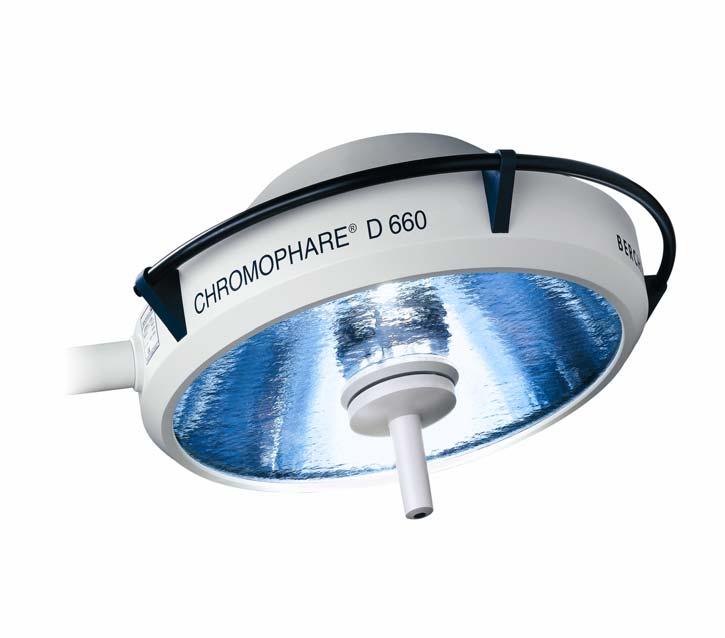
1 CHROMOPHARE D650, D660, D530, & D540 PREINSTALLATION MANUAL
2 Pre-Install Manual: Related Publications: Operator Manual This manual contains proprietary information of BERCHTOLD Corporation. It shall not be reproduced in whole or in part without the written permission of BERCHTOLD Corporation. ETL/CETL LISTED TO IEC MEDICAL ELECTRICAL EQUIPMENT CHROMOPHARE IS A REGISTERED TRADEMARK OF BERCHTOLD CORPORATION.
3 PRE-INSTALLATION GUIDE TABLE OF CONTENTS TABLE OF CONTENTS INTRODUCTION & GENERAL INFORMATION...2 SUPERSTRUCTURE DESIGN AND SPECIFICATION INFORMATION...3 RECOMMENDED DESIGN SPECIFICATIONS...3 MINIMUM DESIGN SPECIFICATIONS BY PRODUCT TYPE...3 ELECTRICAL REQUIREMENTS...5 ELECTRICAL REQUIREMENTS FOR STANDARD MOUNTING...5 STANDARD MOUNTING DETAILS (SEE PAGE 6 FOR LAYOUT DIAGRAM)...6 LOW PROFILE MOUNTING LAYOUT DIAGRAM...7 LOW PROFILE MOUNTING DETAILS (SEE PAGE 7 FOR LAYOUT DIAGRAM)...8 FLAT PANEL PRODUCTS (WITH AND WITHOUT LIGHTS)...9 WALL CONTROL BOX DIMENSIONS...10 SK BOX DIMENSIONS...10 PRE-INSTALLATION GUIDE PUBLICATION HISTORY...11 PUBLICATION HISTORY...11 REV Page 1
4 INTRODUCTION & GENERAL INFORMATION PRE-INSTALLATION GUIDE INTRODUCTION & GENERAL INFORMATION This Pre-Installation Guide details and describes the structural, mechanical, and electrical requirements of the room or site to allow proper installation of BERCHTOLD CHROMOPHARE D-Series Surgical Lights and Flat Panel products. (D-Series Surgical Lights include D650, D660, D530, and D540.) It is intended for use by technical individuals involved in the specification, design, and construction of the room or site, such as architects, structural engineers, contractors, electricians, and pipe fitters. The Hospital and/or its contractors are responsible for the preparation of the room or site including the superstructure design and installation and all other mechanical and electrical requirements described within this guide and those specified by AHJ (Authorities Having Jurisdiction). Painting and flooring need to be completed before the product can be installed. Questions pertaining to the information contained in this guide can be addressed by contacting your local BERCHTOLD Technical Service Representative or BERCHTOLD Technical Service at This guide is applicable to the following BERCHTOLD products: CHROMOPHARE D650 and D660 CHROMOPHARE D530 and D540 All multiple combinations of the CHROMOPHARE D-Series. Stand alone Flat Panel Products Flat Panel combined with either one or two CHROMOPHARE D-Series lights REV. 2 Page 2
5 PRE-INSTALLATION GUIDE SUPERSTRUCTURE DESIGN AND SPECIFICATION INFORMATION SUPERSTRUCTURE DESIGN AND SPECIFICATION INFORMATION The customer/contractor has responsibility to ensure the superstructure design meets specifications. BERCHTOLD recommends that a Structural Engineer be involved in the design of the superstructure. Important: Weights and moments must be adjusted when designing for use in seismic zones. Check with your local construction-engineering agency for applicable local and state codes. RECOMMENDED DESIGN SPECIFICATIONS BERCHTOLD Corporation STRONGLY recommends that the superstructure be designed to meet the following specifications. (Reference drawing on next page). Designing to these specifications will allow combinations of Light or Flat Panel product to be hung from the structure. Product Type Weight (T) Moment (M) lbs. ft-lb with less than 0.1 º Light / Flat Panel Combinations Loads to support structure Case Fp Tmax (LBS) Vmax (LBS) Mmax (Ft-#) MINIMUM DESIGN SPECIFICATIONS BY PRODUCT TYPE If the customer decides to design the superstructure to the requirements of the specific product type, the superstructure design specifications can be found in the table below. Product Type Weight (T) lbs. Moment (M) ft-lb with less than 0.1 º rotation at Single Light Double Light or Double Flat Panel Triple Light Flat Panel only Single Light with Flat Panel Double Light with Flat Panel Single Light with Double Flat Panel REV Page 3
6 PRE-INSTALLATION GUIDE SUPERSTRUCTURE DESIGN AND SPECIFICATION INFORMATION A representative superstructure is shown below. The engineer of record must verify that any structure meets all applicable building codes, especially in seismic zones. Important design notes: 1. Four (4) kickers are needed. 2. Kickers should be anchored (welding preferred) to the mounting ring as shown in Detail A. Do NOT anchor to vertical pipe. 3. The Mounting Ring (provided by BERCHTOLD) should be installed flush with the ceiling with the studs pointing down. Call for additional details. NOTES: 1. LOAD USED FOR DESIGN: TOTAL WT.: LB. MAX. STATIC TORQUE 1538 FT-LB 2. MOUNTING RING IS DESIGNED FOR A MAXIMUM BRACE FORCE OF IN BRACING CONFIGURATION SHOWN Mounting Ring ¾ X 12 Internally Threaded Holes for Threaded Rods. Plate Supplied By BERCHTOLD. 6-7/8 Hole PLAN A-A Superstructure Design See Specifications on Page REV. 2 Page 4
7 ELECTRICAL REQUIREMENTS PRE-INSTALLATION GUIDE ELECTRICAL REQUIREMENTS Hospital/Contractor has responsibility for completing all wiring and conduit runs detailed below BEFORE the product can be installed. ELECTRICAL REQUIREMENTS FOR STANDARD MOUNTING Check with Site Project Manager or BERCHTOLD Customer Service to determine whether Standard Mounting or Low Profile Mounting style is to be used. Standard Mounting Layout Diagram (see page 6 for details and description) REV Page 5
8 ELECTRICAL REQUIREMENTS PRE-INSTALLATION GUIDE STANDARD MOUNTING DETAILS (SEE PAGE 5 FOR LAYOUT DIAGRAM) 1. AC Wiring Wiring should be 3 wire, 14AWG min., and 600V. Wiring for lights should be flexible conduit exiting ceiling at the mounting ring and falling 18, min., below ceiling. CHROMOPHARE lights require a 120VAC, 50/60 Hz supply. BERCHTOLD recommends a separate 120VAC supply for each mounting ring. Each light head draws 2 Amps. 2. Conduit and boxes A standard 4X4 junction box should be installed in the wall for mounting of the light Wall Control. Front of box should be flush with the wall. BERCHTOLD suggests that this box be located approximately 53 off the floor. For each mounting ring a minimum 1 conduit, with finish grommets at each end, should be installed from the Wall Control junction box and terminated as close to the mounting ring as possible. Note: Conduit openings need to be easily accessible at both ends. 3. Optional Equipment (Contractors please check with customer to see if any options are to be installed.) ChromoVision camera system - Minimum 1 conduit, with finish grommets at each end, should be installed from the mounting ring to either a junction box used for mounting the camera control or the documentation console, per customer specification. Communication Interface Systems Conduit as required by the manufacturer of the interface unit REV. 2 Page 6
9 PRE-INSTALLATION GUIDE ELECTRICAL REQUIREMENTS LOW PROFILE MOUNTING LAYOUT DIAGRAM (See page 8 for details and description) REV Page 7
10 ELECTRICAL REQUIREMENTS PRE-INSTALLATION GUIDE LOW PROFILE MOUNTING DETAILS (SEE PAGE 7 FOR LAYOUT DIAGRAM) 1. SK Box Mounting SK box must be mounted within 10 of mounting ring and be easily accessible. An access panel close to the box mounting location is recommended. Single Light SK box weighs approximately 30 lbs.; double Light SK box weighs approximately 50 lbs. 2. AC Wiring (to input of SK box) AC supply should be 120VAC, 50/60 Hz. Wiring to be 3 wires, 14AWG min., 600V rated wire and run per local code to the SK box and terminated to the fused terminal block inside the SK box. Each light head draws 2 Amps. 3. DC Wiring (from SK Box to Mounting Ring) 12 AWG, 600 volt, 1 pair per light head and 1 ground wire per mounting ring. Wire is terminated to the non-fused terminal block inside the SK box. Wiring should run from output of SK box and fall 18, min., from ceiling at the mounting ring. 4. Conduit and boxes A standard 4X4 junction box should be installed in the wall for mounting of the light Wall Control. Front of box should be flush with the wall. BERCHTOLD suggests that this box be located approximately 53 off the floor. Minimum 1 conduit, with finish grommets at each end, should be installed from the Wall Control junction box and terminated at the SK box AC wiring As required by local code. DC wiring As required by local code. Note: Conduit openings need to be easily accessible at both ends. 5. Optional Equipment (Contractors please check with customer to see if any options are to be installed.) ChromoVision camera system - Minimum 1 conduit, with finish grommets at each end, should be installed from the SK box to either a junction box used for mounting the camera control or the documentation console, per customer specification. Note: Conduit openings need to be easily accessible at both ends. Communication Interface Systems Conduit as required by the manufacturer of the interface unit REV. 2 Page 8
11 PRE-INSTALLATION GUIDE ELECTRICAL REQUIREMENTS FLAT PANEL PRODUCTS (WITH AND WITHOUT LIGHTS) When included as part of a Light assembly: 1. AC wiring (In addition to Light AC wiring) Should be 3 wire, 14AWG min., and 600V. Conduit as required by local code. Wiring should exit ceiling at the mounting ring and fall 18, min., below ceiling. 2. Low voltage video cable conduit If conduit for low voltage cable is required by code then BERCHTOLD suggests 2 conduit to allow for the various types and quantities of video cabling that can be run. Conduit should run from the mounting ring to a destination determined by the customer. Note: Conduit openings need to be easily accessible at both ends. Stand Alone Flat Panel Products: 1. AC wiring Should be 3 wire, 14AWG min., 600V. Conduit as required by local code. Wiring should exit ceiling at the mounting ring and fall 18, min., below ceiling. 2. Low voltage video cable conduit If conduit for low voltage cable is required by code then BERCHTOLD suggests 2 conduit to allow for the various types and quantities of video cabling that can be run. Conduit should run from the mounting ring to a destination determined by the customer. Note: Conduit openings need to be easily accessible at both ends. REV Page 9
12 BOX DIMENSIONS PRE-INSTALLATION GUIDE WALL CONTROL BOX DIMENSIONS Back Panel (BERCHTOLD Dwg ) SK BOX DIMENSIONS SK Box for Single & Double Light Note: Triple light uses one double SK box and one single SK box. BERCHTOLD dwg , Hoffman Engineering No. A-14N126 REV Page 10
13 PRE-INSTALLATION GUIDE PUBLICATION HISTORY PRE-INSTALLATION GUIDE PUBLICATION HISTORY This publication describes the equipment as of the date of issue listed below. BERCHTOLD Corporation reserves the right to make changes in design or specifications at any time without notice. If you find any difference between the equipment you received and the components or assemblies described in this publication, contact BERCHTOLD Customer Service at for information. PUBLICATION HISTORY Revision Issue Date Revision 1 Original Issue: September 2002 (ECO 20149) Revision 2 November (ECO 21108) TELETOM is a Registered Trademark of BERCHTOLD Corporation BERCHTOLD Corporation. All Rights Reserved REV Page 11
14 SAFE INNOVATIVE BERCHTOLD BERCHTOLD Corporation 1950 Hanahan Road Charleston, SC Phone: Phone: Fax: Manual No
TELETOM EQUIPMENT MANAGEMENT SYSTEMS
 TELETOM EQUIPMENT S VERSATILE USA MANUFACTURED EACH TELETOM IS CUSTOM-CONFIGURED, ASSEMBLED AND TESTED PRIOR TO SHIPPING ENSURING GREATER RELIABILITY AND A MORE TIMELY ON-SITE INSTALLATION. ACCESSORIES
Ceiling Mount Pre-Installation Guidelines
 Ceiling Mount Pre-Installation Guidelines This guide is a general overview of the mounting requirements, not full installation instructions. It is recommended that the full installation manual be completely
Control Panel 2.0 Installation Guide
 Control Panel 2.0 Installation Guide Product Description The View Control Panel 2.0 houses the control components and power source that are responsible for the operation of a View Dynamic Glass system.
30901 TL-15 UNITIZED AHD AND RECEIVING SAFE WITH SECUROMATIC AFTER HOUR DEPOSITORY WALK-UP
 L909 CALL -800-999-00 090 TL- UNITIZED AHD AND RECEIVING SAFE WITH SECUROMATIC AFTER HOUR DEPOSITORY WALK-UP SPECIFICATIONS SAFE: mm ( CARBON STEEL PLATE, WELDED CONSTRUCTION. DOOR: 2mm (") STEEL LAMINATED
DENVER PUBLIC SCHOOLS DESIGN AND CONSTRUCTION STANDARDS This Standard is for guidance only. SECTION PUMPS
 PART 0 A/E INSTRUCTIONS 0.01 Design Requirements A. Pumping system design 1. A primary-secondary pumping system is preferred. Redundant pipes are required for chillers and boilers. 2. Select pumps to operate
Model 9001, Alarm
 INSTALLATION, OPERATION & MAINTENANCE INSTRUCTIONS 1455 Kleppe Lane Sparks, NV 89431-6467 (775) 359-4712 Fax (775) 359-7424 E-mail: haws@hawsco.com website: www.hawsco.com No. 2080202(27) Model 9001, 9001.5
Sidel Combi-Combi Therm & CO2 Counter Installation Guide
 Sidel Combi-Combi Therm & CO2 Counter Installation Guide Introduction Thank you for purchasing the Sidel Combi-Combi Therm & CO 2 Counter. The Combi-Combi Therm & CO 2 Counter control panel should be installed
Total Articulating Service Column - TASC 2000 Series
 Total Articulating Service Column - TASC 2000 Series lements The TASC Pendant is available in single and double arm configurations ach joint has a rotation range up to 330 Pendant head can be custom-designed
RELEASE DEVICES RELEASE DEVICE-WPS MODELS A/B INSTALLATION MANUAL U.L. LISTED CANADIAN LISTED CSFM: :100 GENERAL DESCRIPTION:
 RELEASE DEVICES MADE IN THE U.S.A. RELEASE DEVICE-WPS MODELS A/B INSTALLATION MANUAL U.L. LISTED CANADIAN LISTED CSFM: 7300-1418:100 GENERAL DESCRIPTION: S/N: The "WPS" World Power Series, Time Delay Release
Model 9001, Alarm
 INSTALLATION, OPERATION & MAINTENANCE INSTRUCTIONS 1455 Kleppe Lane Sparks, NV 89431-6467 (775) 359-4712 Fax (775) 359-7424 E-mail: haws@hawsco.com website: www.hawsco.com Model 9001, 9001.5 Alarm No.
Firefly II Multi Voltage RELEASE DEVICES. Firefly II & IIB-MV INSTALLATION MANUAL
 Firefly II Multi Voltage RELEASE DEVICES Firefly II & IIB-MV INSTALLATION MANUAL GENERAL DESCRIPTION: S/N The The Cookson Company Firefly II-MV time delay release devices are designed for use on rolling
ACSI MODEL 1410 POWER SUPPLY INSTALLATION INSTRUCTIONS
 II 1400-3 ACSI MODEL 1410 POWER SUPPLY INSTALLATION INSTRUCTIONS Features: For use with doors or groups of doors that must interlock with each other to regulate control of accessing one area from another,
RV30, RV36, RV46. 30, 36, 46 Wide, Raised Vent. Adjustable anchor legs. Front View
 Document # PG08-003 Revised 04/30/09 Page 1/7 1/2 (13 mm) thick stiffener across back 3 1/8" (79 mm) 2" (51 mm) 1 15/16" (49 mm) 1 13/16" (46 mm) 3/16" (5 mm) 2 5/16" (59 mm) Top cap with vent down 15/16"
MANUAL RESET ALARM RELEASE
 Fire Door Release MODEL AR-D MANUAL RESET ALARM RELEASE INSTRUCTION MANUAL AR-D GENERAL INFORMATION 1. Review all installation instructions, procedures, cautions and warnings contained within this manual
ACSI AO ELECTRIC LATCH RETRACTION CONTROLLER INSTALLATION INSTRUCTIONS I.D. 1089, REV. F
 II 1400-2 ACSI 1406-04-AO ELECTRIC LATCH RETRACTION CONTROLLER INSTALLATION INSTRUCTIONS I.D. 1089, REV. F INSTALLATION Transformer Model BE31763001 by Basler Electric, Transformer Model 2010028 by Galaxy
SOLID STATE SECURITIES, INC. THE "SS90" SERIES RELEASE DEVICES MADE IN THE U.S.A. SS90-WPS MODEL A/B INSTALLATION MANUAL
 S S S S S S LISTED L * PATENT PENDING S S 90 OLID TATE ECURITIES, INC SOLID STATE FAIL-SAFE UNIT U 99Y9 RESET RELEASING DEVICE SOLID STATE SECURITIES, INC. THE "SS90" SERIES RELEASE DEVICES MADE IN THE
120 VOLT POTENTIAL PRESENT. MAKE SURE POWER INPUT TO UNIT IS TURNED OFF DURING INSTALLATION AND WIRING PROCEDURE.
 00000 (0) 00 PowerMatic Low Energy Power Operator Wiring Instructions 0 VOLT POTENTIAL PRESENT. MAKE SURE POWER INPUT TO UNIT IS TURNED OFF DURING INSTALLATION AND WIRING PROCEDURE. REQUIREMENTS: U.L.
Operating & Maintenance Manual. Alert-4 Ethernet LCD Master Alarm
 Operating & Maintenance Manual Alert-4 Ethernet LCD Master Alarm w w w. a m i c o. c o m Contents User Responsibility 4 Introduction 4 Features 5 Description of the Alarm 5 Shipment Details 5 The Alarm
UHIR Series. Horizontal or Vertical Mounting Industrial / Commercial Electric Unit Heater. Owner s Manual
 UHIR Series Horizontal or Vertical Mounting Industrial / Commercial Electric Unit Heater Owner s Manual This manual covers installation, maintenance and repair parts. Read carefully before attempting to
DPM-G DPM-CR DPM-W DPM-B INDOOR DOME PENDANT MOUNT INSTALLATION MANUAL
 DPM-G DPM-CR DPM-W DPM-B INDOOR DOME PENDANT MOUNT INSTALLATION MANUAL MANUAL NUMBERS 517646-1960 517645-1960 517702-1960 517783-1960 Ultrak, Inc. 4465 Coonpath Road NW Carroll, OH 43112 (740) 756-9222
A m e r i c a s D e n t a l E q u i p m e n t C o m p a n y. Rev 2/15. D a n s e r e a u
 A m e r i c a s D e n t a l E q u i p m e n t C o m p a n y Rev 2/15 D a n s e r e a u (8 0 0 ) 423-5657 / WWW.DHPDENTAL.COM CUSTOMER SUPPORT INF ORMATION Dansereau Health Products, Inc. has been manufacturing
OPR Power Series AC to DC POWER SUPPLY SERIES WITH REMOTE MANAGEMENT AND ALARM SYSTEMS. Model Nos. OPR200-24S / OPR200-24R. Manual
 OPR Power Series AC to DC POWER SUPPLY SERIES WITH REMOTE MANAGEMENT AND ALARM SYSTEMS Model Nos. OPR200-24S / OPR200-24R Manual Revision F May 2010 Optimal Power Supplies LLC www.optimal-power.com i PROPRIETARY
Proximity Series. features: specifications: options: in-wall box. what great systems are built on.
 in-wall box bring technology from the rack to the display with flexible and efficient storage of devices, cables and power for complete, reliable AV systems. features: Available in two sizes to fit the
Installing the Cisco ONS FAP-4 Fuse Alarm Panel
 Installing the Cisco ONS 15454-FAP-4 Fuse Alarm Panel Product Number: 15454-FAP-4= This document explains how to install, test, operate, and maintain the Cisco ONS 15454-FAP-4 fuse alarm panel. This document
ecolor Graze Powercore Linear LED surface light for wall washing and grazing
 Linear LED surface light for wall washing and grazing Linear LED surface light for wall washing and grazing linear LED lighting fixtures are ideal for surface grazing and wall-washing applications that
HARMONY LED385 EXAMINATION LIGHTING SYSTEM
 HARMONY LED385 EXAMINATION LIGHTING SYSTEM APPLICATION The Harmony LED385 Examination Lighting System, available in two configurations, is a variable intensity light for examination, treatment, critical
Guidelines for Earthquake Bracing of Residential Water Heaters
 Guidelines for Earthquake Bracing of Residential Water Heaters Department of General Services Division of the State Architect 1102 Q Street, Suite 5100 Sacramento, CA 95814 Phone: (916) 324-7099 Fax: (916)
Access Point Mounting Instructions
 Published: November 8, 010 Revised: November 9, 011 Contents Introduction, page 1 Mounting Hardware, page 1 Mounting an Access Point Below a Suspended Ceiling, page 5 Mounting an Access Point on a Hard
92 RAILWAY ST. SEAFORTH, ONTARIO CANADA, N0K 1W0 TEL: ABSOLUTE AIR INSTALLATION MANUAL
 92 RAILWAY ST. SEAFORTH, ONTARIO CANADA, N0K 1W0 TEL: 519-527- 2198 ABSOLUTE AIR INSTALLATION MANUAL 2014-04-10 PAGE 1 OF 18 REV 3 TABLE OF CONTENTS 1 INSTALLATION GUIDELINES FOR ABSOLUTE AIR FAN... 3
PRE-INSTALLATION GUIDE for MODELS
 DENTAL VACUUM SYSTEMS PRE-INSTALLATION GUIDE for MODELS VS50NEO & VS80NEO Check VacStar NEO Model Being Installed: VS50NEO VS80NEO Doctor: Address: Phone#: Dealer: Dealer Address: PRODUCT SPECIFICATIONS
THE "SS90" SERIES RELEASE DEVICES MADE IN THE U.S.A. MODELS A/B INSTALLATION MANUAL
 S S S S S S OLID TATE ECURITIES, INC S S 90 SOLID STATE FAIL-SAFE UNIT * PATENT PENDING LISTED 99Y9 RESET U L RELEASING DEVICE SOLID STATE SECURITIES, INC. THE "SS90" SERIES RELEASE DEVICES MADE IN THE
SAPS GUARDRAIL CONCRETE
 SAPS GUARDRAIL CONCRETE The SAPS guardrail for concrete applications attaches to an embedded anchor and provides a 5000 lb point of tie-off. The 42 inch and 60 inch models meet OSHA height requirements.
OPERATION MANUAL. Move it. Hang it. Rack it. Stack it. MaxPower Corporation 230 Yuma Street Denver, CO
 OPERATION MANUAL Complete Instructions for and Operation MaxPower Corporation 230 Yuma Street Denver, CO 80223 800-576-3966 www.coolcube10.com Move it. Hang it. Rack it. Stack it. 05/05 P/N: 5-TC600-2510
CLASSIC. SIDE CABINET Installation Instructions
 CLASSIC SIDE CABINET Installation Instructions THIS MANUAL IS FOR AUTHORIZED AND QUALIFIED INSTALLATION PERSONAL ONLY! Table of Contents General Information...3 CCS Overview...4 CCS Cabinet Dimensions...5
MADE IN THE U.S.A. MODELS A/B INSTALLATION MANUAL
 RELEASE DEVICES MADE IN THE U.S.A. MODELS A/B INSTALLATION MANUAL U.L. LISTED CANADIAN LISTED CSFM: 7300-1418:100 GENERAL DESCRIPTION: S/N: These Time Delay Release Devices are U.L. Listed, Canadian Listed,
Emergency Lighting Transfer System Model: ELTS2 Installation and User Operation Manual
 Emergency Lighting Transfer System Model: ELTS2 Installation and User Operation Manual Part Number: 1096M1200 Rev: E Released: 2018-07 ETC is a registered trademark of Electronic Theatre Controls, Inc.
PRE-INSTALLATION GUIDE for MODELS
 DENTAL VACUUM SYSTEMS PRE-INSTALLATION GUIDE for MODELS VS20NEO & VS40NEO Check VacStar NEO Model Being Installed: VS20NEO VS40NEO Model VS20NEO Model VS40NEO Doctor: Address: Phone#: Dealer: Dealer Address:
SERVICE PARTS/OPERATION for
 T--357 Manual SERVICE PARTS/OPERATION for MCC Heater Units 12-XXXX Series T -357 REV. 05/2015 2012 Mobile Climate Control Table of Contents SAFETY SUMMARY... Safety-1 UNIT SPECIFICATIONS... Spec-1 MAINTENANCE...
Model 9001EXP Alarm. NOTE TO INSTALLER: Please leave this information with the Maintenance Department. LIMITED WARRANTY
 INSTALLATION, OPERATION & MAINTENANCE INSTRUCTIONS 1455 Kleppe Lane Sparks, NV 89431-6467 (775) 359-4712 Fax (775) 359-7424 E-mail: haws@hawsco.com website: www.hawsco.com Model 9001EXP Alarm No. 2080203(24)
Elements Headwall System (P2008A)
") Figure 1. Elements Headwall System American Society of Mechanical Engineers 3 (ASME ) ASME B16.22: Wrought Copper and Copper Alloy Solder Joint Pressure Fittings American Standard Test Method 4 International
Figure 1. Elements Headwall System American Society of Mechanical Engineers 3 (ASME ) ASME B16.22: Wrought Copper and Copper Alloy Solder Joint Pressure Fittings American Standard Test Method 4 International
WARNING. Installation Tip: Try out this unit before installing onto a fire door system. Test and learn the release INTRODUCTION
 WARNING 1. CAUTION: Review all installation instructions, procedures, cautions and warnings contained within this manual prior to installing and/or servicing this product. As with all releasing device
PRE-INSTALLATION GUIDE
 Dry Vacuum System Part Numbers V15, 2V15, 3V15 and 4V15 PRE-INSTALLATION GUIDE All pumps comply with NFPA 99C level 3 reuirements. All installations must conform to local codes. System being installed:
AVANI Grinding Booth
 AVANI Grinding Booth GB-6066-DD Customer: Kelly Walsh Customer PO#: 11305 AVANI SO#: Serial #: 153920-153921 Ship Date / Install Date: Tested By: Please read and save these instructions. Read carefully
MANUAL RESET ALARM RELEASE
 Fire Door Release MODEL AR-D2 MANUAL RESET ALARM RELEASE INSTRUCTION MANUAL AR-D2 GENERAL INFORMATION 1. Review all installation instructions, procedures, cautions and warnings contained within this manual
CATALOGUE. Request to Exit Products Relays, Fuses & Timers TROJAN DEVELOPMENTS Product Catalogue.
 CATALOGUE 2018 Product Catalogue Request to Exit Products Relays, Fuses & Timers CONTENTS Table of Contents Introduction: 3 Request & Emergency Egress Devices: Prox Rex 4 Press Rex 5 Em Rex 6 Smart Em
MODELS SafeSite LED Linear, Class I Div. 1 2 & 4 Versions
 INSTALLATION AND MAINTENANCE MANUAL SAFESITE LED LINEAR FIXTURE Document No: 9100-127-1402-99 Rev K December, 2016 MODELS SafeSite LED Linear, Class I Div. 1 2 & 4 Versions SUITABLE FOR WET LOCATIONS in
INSTALLATION INSTRUCTIONS
 INSTALLATION INSTRUCTIONS Flow Lighting QuickLED NEW FIXTURE 2x4 2x2 1x4 Corporate 1240 Texan Trail, Suite 102 Grapevine, TX 76051 (817)435-8484 Office www.flowledlighting.com READ AND FOLLOW ALL SAFETY
Sprinkler Permit Applications
 REQUIREMENTS FOR NFPA 13 SYSTEM Building Inspections Sprinkler Permit Applications A complete application for a Sprinkler Permit will comply with the requirements of Chapter 8 of NFPA 13. Hydraulic calculations
5900 Series X-in Low Energy Power Operator
 5900 Series X-in Low Energy Power Operator INTRODUCTION The Norton 5900 Series X-in is a full-featured, extremely quiet, low energy door operator designed for moderate to high traffic doors. This cost-effective
SECTION WET-PIPE SPRINKLER SYSTEMS EASY RISER CHECK VALVE
 SECTION 21 1313 WET-PIPE SPRINKLER SYSTEMS PART 1 GENERAL 1.01 SECTION INCLUDES A. Wet-pipe sprinkler system. B. System design, installation, and certification. C. Fire department connections. 1.02 RELATED
FIGURE 1 MODEL RFIII ECLH CONCEALED HSW SPRINKLER ASSEMBLY AND FEATURES. 5/16" (7,9 mm) MIN. 9/16" (14,3 mm) MAX.
 MIN. 9/16 (14,3 mm) MAX.") Worldwide Contacts www.tyco-fire.com Model RFIII 8.0 K-factor Flat Plate Concealed Horizontal Extended Coverage Quick Response Light Hazard Sidewall Sprinkler General Description Response Sprinkler is
Worldwide Contacts www.tyco-fire.com Model RFIII 8.0 K-factor Flat Plate Concealed Horizontal Extended Coverage Quick Response Light Hazard Sidewall Sprinkler General Description Response Sprinkler is
Product Data. FF1DNA, FF1DNE Fan Coil Units. Sizes 018 thru 030 FEATURES/BENEFITS
 Product Data FF1DNA, FF1DNE Fan Coil Units Sizes 018 thru 030 FF1D FEATURES/BENEFITS The FF1DNA and FF1DNE Fan Coil units are designed as upflow indoor air handlers for split-system heat pumps and air
/9308 External Battery Chargers Installation Instructions
 4081-9306/9308 External Battery Chargers Installation Instructions Introduction This publication describes the installation procedure for an External Battery Charger used with the 4100U or 4100ES System.
SPECIFICATIONS: FIREGUARD CROSS CORRIDOR CC
 SPECIFICATIONS: FIREGUARD CROSS CORRIDOR CC SECTION 08 35 13.23 ACCORDION FOLDING FIRE DOORS PART 1 GENERAL 1.01 SUMMARY OF WORK A. Division 0 and 1, as indexed, apply to this section. B. Furnish and install
FIRE ALARM: BY OTHERS, IF REQUIRED.
 x x x x x x OS LIGHTING S FLUORESCENT LIGHT FIXTURE, SEE LIGHT FIXTURE SCHEDULE FOR SIZE AND MOUNTING. FLUORESCENT STRIP LIGHT FIXTURE, SEE LIGHT FIXTURE SCHEDULE FOR SIZE AND MOUNTING. WALL BRACKET FLUORESCENT
2409/2900. Fire Guard
 2409/2900 Fire Guard Table of Contents Features and Additional Fire Opening Devices... 1 2409 Single-Point Hold Open Applications and Mounting Details... 2 2409 Track Assemblies, Arms and Components...
Cooktop Chimney Ventilation Hoods
 INSTALLATION GUIDE Cooktop Chimney Ventilation Hoods Contents Wolf Cooktop Chimney Ventilation Hoods.......... 3 Cooktop Chimney Hood Specifications............ 4 Cooktop Chimney Hood Installation.............
GAS MONITOR Model Model
 Sierra Monitor Corporation 1991 Tarob Court, Milpitas, CA 95035 (408) 262-6611 (800) 727-4377 (408) 262-9042 - Fax E-mail: sierra@sierramonitor.com Web Site: www.sierramonitor.com GAS MONITOR Model 2350-00
IVR15-RPS O.D. Solid State Illuminated Rail Remote Power Supply
 IVR15RPS O.D. Solid State Illuminated Rail Remote Power Supply 1.50 recognized 0.3 90 APERTURE Ends of Illuminated rail field cutable to a minimum of 2 1/8 in length. Illuminated rail is available with
FIRE ALARM: BY OTHERS, IF REQUIRED.
 x x x x x x OS LIGHTING S FLUORESCENT LIGHT FIXTURE, SEE LIGHT FIXTURE SCHEDULE FOR SIZE AND MOUNTING. CAPITAL LETTER DENOTES TYPE, LOWER CASE LETTER DENOTES SWITCH LEG. FLUORESCENT STRIP LIGHT FIXTURE,
Installation and Operation Manual Low Power (LP) DC Power System
 DC Power System") Installation and Operation Manual Low Power (LP) DC Power System LPS Power Enclosure LPB Battery Enclosure 2051259 R3 Information in this document is subject to change without notice and does not represent
Installation and Operation Manual Low Power (LP) DC Power System LPS Power Enclosure LPB Battery Enclosure 2051259 R3 Information in this document is subject to change without notice and does not represent
Installation, Operation and Maintenance Instructions
 Installation, Operation and Maintenance Instructions Speakman Company Safe-T-Zone Heat Traced Emergency Stations You have selected the designated item: SE-7001 OTHER: SERIAL NO: 3/08 Rev-3 92-2904 INSTALLATION
Detection System Model 3500 Series
 Detection System Model 3500 Series Architect/Contractor Information Package 3M Library Systems 3M Center, Building 225-4N-14 St. Paul, Minnesota 55144-1000 Copyright 2001-2006 3M. All rights reserved.
Section COMMUNICATION EQUIPMENT ROOM FITTINGS. Section Communications Cabinets, Racks, Frames and Enclosures
 PART 1 GENERAL 1.1 WORK INCLUDED Section 27 11 00 COMMUNICATION EQUIPMENT ROOM FITTINGS Section 27 11 16 Communications Cabinets, Racks, Frames and Enclosures A. Provide all labor, materials, and equipment
Installation Instructions. PS902 Power Supply. These instructions cover the following parts: PS902 Power Supply Specifi cations:
 F1! 44487023 These instructions cover the following parts: PS902 Power Supply Installation Instructions! DANGER: To avoid risk of electric shock, turn off AC power before installing or servicing PS902
PS6 SERIES. Installation PS6 SERIES. Power Supplies c/w Fire Panel Interface, EOL Trigger and Standby Power Option
 Installation PS6 SERIES Power Supplies PS6 SERIES Power Supplies c/w Fire Panel Interface, EOL Trigger and Standby Power Option Installation and Specifications Manual ISDPS6_SERIES 08121590 PCN15016 R05/15GR
Installation Instructions 30 French Door Built-in Wall Ovens
 Installation Instructions 30 French Door Built-in Wall Ovens Questions? Call 1.800.GE.CARES (1.800.432.2737) or visit www.geappliances.com In Canada, call 1.800.561.3344 or visit www.geappliances.ca DESIGN
SECTION SPRINKLER SYSTEMS
 SECTION 15325 SPRINKLER SYSTEMS PART 1 - GENERAL 1.1 SECTION INCLUDES A. Wet-pipe sprinkler systems. B. Preaction sprinkler systems. C. System design, installation, and certification. D. Fire department
B. Configuration of system shall be through Schneider Electric in Homewood, Illinois (Jerry Lanfear ).
.") SECTION 28 13 00 - ACCESS CONTROL PART I - GENERAL 1.1 SUMMARY A. This specification section describes the furnishing, installation, commissioning, and programming of a complete, turnkey, hardwired Andover
SECTION 28 13 00 - ACCESS CONTROL PART I - GENERAL 1.1 SUMMARY A. This specification section describes the furnishing, installation, commissioning, and programming of a complete, turnkey, hardwired Andover
Installation/Owner s Manual Models 1504 / 1506
 Installation/Owner s Manual Models / Programmable Stand Alone Digital Keypad Entry Devices Use this manual for circuit board - Revision G or higher. --H--7 Control a main entry point plus an additional
OCH-SSE series Direct Wired Units Indoor * and Outdoor Comfort Heaters
 TPI Corporation P.O. Box 4973 Johnson City, TN 37601 www.tpicorp.com OCH-SSE series Direct Wired Units Indoor * and Outdoor Comfort Heaters *EXCLUDING RESIDENCES IMPORTANT SAFETY INFORMATION INSIDE possible
Single Point Freeze Protection Heat Trace Control TRACON MODEL FPT 130 Installation and Operation Manual
 We manage heat MANUAL Single Point Freeze Protection Heat Trace Control TRACON MODEL FPT 130 Installation and Operation Manual 1850 N Sheridan Street South Bend, Indiana 46628 (574) 233-1202 or (800) 234-4239
Use & Care Manual. Electric Tankless Water Heaters. With Installation Instructions for the Installer AP15447 (10/10)
") Use & Care Manual With Installation Instructions for the Installer Electric Tankless Water Heaters The purpose of this manual is twofold: one, to provide the installer with the basic directions and recommendations
Use & Care Manual With Installation Instructions for the Installer Electric Tankless Water Heaters The purpose of this manual is twofold: one, to provide the installer with the basic directions and recommendations
INSTALLATION INSTRUCTIONS FOR 6532 SERIES PACKAGE HEAT PUMP
 INSTALLATION INSTRUCTIONS FOR 6532 SERIES PACKAGE HEAT PUMP RV Products A Division of Airxcel, Inc. P.O. Box 4020 Wichita, KS 67204 1976-360 (1-02) PP TABLE OF CONTENTS 1. Warnings......................................................
5900 SERIES Low Energy Power Operator
 Low Energy Power Operator introduction The Norton 5900 Series is a full-featured, extremely quiet, low energy door operator designed for moderate to high traffic doors. This cost-effective operator is
MECKLENBURG COUNTY. Land Use and Environmental Service Agency Code Enforcement 8/10/11 ELECTRICAL CONSISTENCY MEETING. Code Consistency Questions
 MECKLENBURG COUNTY Land Use and Environmental Service Agency Code Enforcement 8/10/11 ELECTRICAL CONSISTENCY MEETING Code Consistency Questions 1. Is low voltage cable allowed to be run through drilled
Model 8140 & 8141 Fresh Air Ventilator Installation and Operations Manual
 Model 8140 & 8141 Fresh Air Ventilator Installation and Operations Manual FILTER COVER VENTILATION CONTROLLER INLET COLLAR OUTLET COLLAR SAFETY INSTRUCTIONS WARNING 1. 120 Volts may cause serious injury
Division 21: FIRE SUPRESSION WET-PIPE SPRINKLER PROTECTION SYSTEM. The Academy Sept Table of Contents 1 Division 21
 Division 21: FIRE SUPRESSION 21 1313 WET-PIPE SPRINKLER PROTECTION SYSTEM Table of Contents 1 Division 21 SECTION 21 1313 WET-PIPE SPRINKLER PROTECTION SYSTEM PART 1 - GENERAL 1.1 RELATED DOCUMENTS A.
Installation, Operation & Service Manual
 Installation, Operation & Service Manual WARNING Improper installation, adjustment, alteration, service or maintenance can result in death, injury or property damage. Read the Installation, Operation and
108A OTP1800. Grid Support. General Description
 Operation Manual 108A OTP1800 ON/OFF Main Switch On/Off Alarm Switch Digital Control Module Grid Support Alarm Fuse 250 Volt 15 amp Load Outlet Sensor Input Inlet General Description This control is a
Classic Twelve O clock Cabinet Installation Instructions
 Classic Twelve O clock Cabinet Installation Instructions CF36 CF42 THIS MANUAL IS FOR AUTHORIZED AND QUALIFIED INSTALLATION PERSONEL ONLY! Table of Contents General Information... 3 CF36 Cabinet Overview...
AIR ONE PROFILER TOP and SIDE DRYER INSTALLATION MANUAL Part # DRYRPROFLRXXXXXX (ALL COLORS)
") AIR ONE PROFILER TOP and SIDE DRYER INSTALLATION MANUAL Part # DRYRPROFLRXXXXXX (ALL COLORS) TABLE OF CONTENTS Equipment Specifications Page: 1 Suggested Tools and Installation Materials Page: 2 Installation
AIR ONE PROFILER TOP and SIDE DRYER INSTALLATION MANUAL Part # DRYRPROFLRXXXXXX (ALL COLORS) TABLE OF CONTENTS Equipment Specifications Page: 1 Suggested Tools and Installation Materials Page: 2 Installation
Clean Air Products 90-Degree Low Profile Left Hand ADA Compliant Air Shower Purchase Specification
 Clean Air Products 90-Degree Low Profile Left Hand ADA Compliant Air Shower Purchase Specification 1. Purpose This specification describes a single person air shower (aka decontamination shower) used to
installation and operation manual for Hunter Ceiling Fans
 For Your Records and Warranty Assistance Model Name: Catalog/Model No.: Serial No.: Date Purchased: Where Purchased: For reference also attach your receipt or a copy of your receipt to the manual. installation
Installation Instructions. Mira LED Light System
 Installation Instructions Mira LED Light System w w w. a m i c o. c o m Contents Symbols Used in This Manual 4 Safety Instructions 5 Variants 7 Scope Of Delivery 8 Installing Mira LED Ceiling Mounted Installing
Installation Instructions Induction Cooktop
 Installation Instructions Induction Cooktop Models: RNCT304 and RNCT365 Part No. 107240 Rev. A Table of Contents Important Safety Instructions... 1 Important Information About Safety Instructions... 1
DONALD H. BERG, ARCHITECT
 DONALD H. BERG, ARCHITECT DVA PROJECT 632-CSI-402 PET/CT ROOM #A0-10 RENOVATION BASEMENT LEVEL, BUILDING 200 ARCHITECT S PROJECT No. 0917-02 ADDENDUM NO. 1 JUNE 25, 2018 Page 1 of 1 ARCHITECTURAL 1. Specifications:
MBCE-110/230FR Flame Sensor Module
 MBCE-1001 FEBRAURY 6, 2017 MBCE-110/230FR Flame Sensor Module exida FMEDA SIL2 SEE NOTE 1 ON PAGE 4 DESCRIPTION The MBCE-110/230FR modules provide visual indication and electrical outputs that signal the
PowerWave 2 Busway System
 PowerWave 2 Busway System Guide Specifications (Revision 004, 11/17/2017) 1 GENERAL 1.1 Summary This specification covers the electrical characteristics and general requirements for a continuous opening,
INSTALLATION INSTRUCTIONS FOR 6536 SERIES TWO TON PACKAGED HEAT PUMP
 INSTALLATION INSTRUCTIONS FOR 6536 SERIES TWO TON PACKAGED HEAT PUMP TABLE OF CONTENTS 1. Warnings...2 2. Component Match-Up...2 3. Unit Depiction Figures...3 4. Blower Performance Data...5 5. General
2 PREPARE THE OPENING
 Installation Instructions 27 & 30 Electric Built-In Wall Ovens Questions? Call 1.800.GE.CARES (1.800.432.2737) or visit www.geappliances.com In Canada, call 1.800.561.3344 or visit www.geappliances.ca
CONTINENTAL METAL PRODUCTS. Stainless Steel Healthcare Equipment Meeting the Demands of the OR. Proudly Made in the USA for over 65 years
 healthcare division CONTINENTAL METAL PRODUCTS Stainless Steel Healthcare Equipment Meeting the Demands of the OR Proudly Made in the USA for over 65 years Surgical Scrub Sinks CMP has been manufacturing
1-1/2 THRU 2-1/2 TONS SPLIT SYSTEM FWM Series
 1-1/2 THRU 2-1/2 TONS SPLIT SYSTEM FWM Series Rated in accordance with ARI Standard 210. Certification applies only when used with proper components as listed with ARI. FEATURES Designed as an upflow indoor
Dual Point General Purpose Heat Trace Control TRACON MODEL GPT 230 Installation and Operation Manual
 We manage heat MANUAL Dual Point General Purpose Heat Trace Control TRACON MODEL GPT 230 Installation and Operation Manual 1850 N Sheridan Street South Bend, Indiana 46628 (574) 233-1202 or (800) 234-4239
ISIMET Series Shop Controller
 ISIMET 5000 6000 Series Shop Controller Installation, Maintenance, Operations, and Start-up Instructions The 5000 / 6000 Series Shop Controllers can be utilized to control multiple utility services, gas
Installation Instructions
 Installation Instructions Electric Drop-In Range JDS28, JDP39 Questions? Call 800.GE.CARES (800.432.2737) or Visit our Website at: ge.com BEFORE YOU BEGIN Read these instructions carefully and completely.
WIDE-DISPERSION FLUSH-MOUNT CEILING SPEAKER
 WIDE-DISPERSION FLUSH-MOUNT CEILING SPEAKER F-282C F-2322C F-232C F-22C F-232SC F-22SC DESCRIPTION TOA introduces a new range of ceiling-mounted speakers that have been designed and engineered to overcome
Colibri. Automatic Tank Gauge CL6 Series Installation Guide
 Colibri Automatic Tank Gauge CL6 Series Installation Guide Manual # Revision Date Changes from Previous Revision 000-2153 C Jan. 2013 Pipe compound brand change, Updated Control drawing. Franklin Fueling
Installation Instructions
 Instructions for Frontload Washers Original Instructions Keep These Instructions for Future Reference. (If this machine changes ownership, this manual must accompany machine.) www.alliancelaundry.com Part
PART 4 ELECTRICAL STANDARDS
 PART 4 ELECTRICAL STANDARDS 1.0 INTRODUCTION AND SCOPE: These standards reflect the general requirements and recommendations of elevator contractors, with respect to the power distribution system to achieve