APPENDIX J. Noise Assessment
|
|
|
- Adelia Robertson
- 6 years ago
- Views:
Transcription
1 APPENDIX J Noise Assessment


2 West Cape Wind Farm Environmental Noise Impact Report September 2006

3 September 19, 2006 Ventus Energy Inc Royal Bank Plaza, South Tower P.O. Box Bay St, Suite 3230 Toronto, Ontario M5J 2J1 Attention: Reference: Mr. Zohrab Mawani, Business Development Manager West Cape Wind Farm Phase II, Environmental Noise Impact Report Dear Mr. Mawani, We are pleased to present an electronic copy of the Environmental Noise Impact Report for all 55 turbines to be installed as part of Phase I and Phase II of the West Cape Wind Farm. This report provides the noise results and conclusions for the West Cape Wind Farm turbine layout provided to MKI by Ventus September 6, 2006 and includes the revised position of turbine C8 confirmed on September 18, The work was performed based on your direction, with input from Hugh Campbell, Vice President of Engineering & Technology with Ventus. This report contains nine sections that describe the site, the methodology, interpretation of results, and conclusions. Three appendices are included which outline building locations around the project, noise level calculations, and turbine noise specifications as provided by the manufacturer. A hard copy of this report will be provided to Ventus Energy Inc. at the conclusion of the study. It is predicted that under several simultaneous worst-case scenarios for noise levels, including a maximum theoretical sound power level of db(a) for the turbines, there is a potential for noise levels at 15 points of reception surrounding the West Cape Wind Farm to be in excess of the voluntary 45 db(a) night-time noise guideline. We would like to thank you and the Ventus staff who assisted with this assessment. Sincerely, M. K. INCE AND ASSOCIATES LTD. Martin Ince, P. Eng. M. K. INCE AND ASSOCIATES LTD.
4 WEST CAPE WIND FARM ENVIRONMENTAL NOISE IMPACT REPORT Ventus Energy Inc West Cape Wind Farm Environmental Noise Impact Report Table of Contents 1.0 Introduction General Description of Wind Turbine Installation Site and Surrounds Description of Receptors Noise Regulations Background West Cape Wind Farm Noise Receptors West Cape Wind Farm Noise Limit Classification Description of Sources Wind Turbine Description Wind Farm Layout Turbine Noise Emission Rating and Data Octave Band Data Tonality Low Frequency Sound Impact Assessment Calculated Noise Levels Noise Model Qualifications Mitigation Measures Conclusions Recommendations Qualifications And Limitations List of Tables Table 1 Table 2 Vestas V-80 General Specifications.4 V80 A-Weighted, Background Corrected, Measured Apparent Sound Power Level...6 List of Figures Figure 1 V80 Noise Emission Curve for db(a) Noise Emission....5 M. K. INCE AND ASSOCIATES LTD. September 19, 2006
5 WEST CAPE WIND FARM ENVIRONMENTAL NOISE IMPACT REPORT List of Appendices Appendix A Appendix B Appendix C West Cape Wind Farm: GPS Co-ordinate List West Cape Wind Farm: Noise Calculations & Map West Cape Wind Farm: Turbine Manufacturer Noise Specifications M. K. INCE AND ASSOCIATES LTD. September 19, 2006
6 WEST CAPE WIND FARM ENVIRONMENTAL NOISE IMPACT REPORT 1.0 INTRODUCTION This report has been produced in accordance with the direction provided by Zohrab Mawani of Ventus Energy Inc (Ventus) to Martin Ince of M.K. Ince & Associates Ltd (MKI). MKI was retained by Ventus to prepare an environmental noise impact assessment for the proposed West Cape Wind Farm(the Project) in Prince County, Prince Edward Island. The report has been produced to fulfill Ventus requirements under the Provincial Environmental Impact Assessment process and the Federal Environmental Screening Assessment process. This report: a) Outlines critical points of noise reception near the project. An additional point of reception was added on June 20, 2006 in order to account for a new residence under construction. b) Discusses noise guidelines in jurisdictions outside of PEI, as well as community noise guidelines set by the World Health Organization. Several considerations raised by Health Canada in reference to another Ventus wind project in PEI are also addressed. c) Suggests a noise limit classification for all points of noise reception. d) Provides a summary of noise levels as predicted by the ISO ( Acoustics- Attenuation of sound during propagation outdoors ) method. The calculations include all 55 turbines that comprise the project. e) Provides maps of the project area with the turbine layouts, noise receptors, and noise contour lines for an assumed turbine noise output of db(a). M. K. INCE AND ASSOCIATES LTD. 1 September 19, 2006
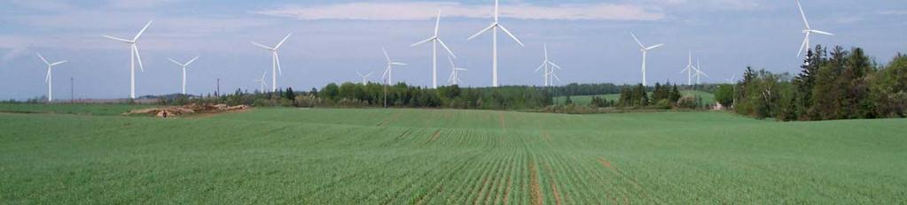
7 WEST CAPE WIND FARM ENVIRONMENTAL NOISE IMPACT REPORT 2.0 GENERAL DESCRIPTION OF WIND TURBINE INSTALLATION SITE AND SURROUNDS The West Cape Wind Farm project area lies on the shores of the West Cape of PEI and is near the community of O Leary in Prince County. The small communities of Springfield West, West Point, Glenwood, Knutsford, Dunblane, Millburn, West Cape, Haliburton and Cape Wolfe lie within or are very near the project area. Land usage in the area is primarily agricultural with some heavily forested areas, which are used for clear-cutting timber and for recreational activities. There are also a number of commercial operations within the region. Cedar Dunes Provincial Park lies approximately 2.5 km south of the project area. Highways 14 & 142 are the main arteries running through the project area and are also the most heavily populated roadways. The majority of dwellings surrounding the Project are full-time residences. The official North Cape Coastal Drive tourist route runs between the project area and PEI s west coast along Highway 14. The topography in the project area features gently rolling hills and farmland, with steep bluffs along much of the surrounding Atlantic Ocean coastline. 3.0 DESCRIPTION OF RECEPTORS 3.1 Noise Regulations Background Acoustic emissions and impacts from wind turbines specifically are currently unregulated in PEI. Federal jurisdiction of noise emissions is concerned with minimizing the health impacts of such emissions. Various other jurisdictions around the world have developed guidelines and regulations pertaining to noise from turbines and noise impact on residents Noise Level Calculation Method and Assumptions Noise levels at potential receptors are predicted with the ISO calculation method Acoustics-attenuation of sound during propagation outdoors. This method accounts for site geometry, atmospheric conditions, and terrain type. For this calculation several worst-case scenarios are assumed: No acoustic shielding or damping from vegetation or buildings etc. Atmospheric conditions for least impeded noise propagation. No meteorological correction factor. Noise calculations are performed with an assumed maximum rated noise emission from the individual wind turbines of db(a). M. K. INCE AND ASSOCIATES LTD. 2 September 19, 2006
8 WEST CAPE WIND FARM ENVIRONMENTAL NOISE IMPACT REPORT The db(a) noise emission value corresponds to the db(a) maximum theoretical noise output of the turbine, described in Section 5.0, plus an additional 2 db(a) due to the uncertainty associated with the theoretical noise curve. This noise emission level is considered to be significantly conservative but is recommended by the manufacturer. Measured octave band noise data for the V80 is not used in the calculations as the theoretical noise emission level used is higher than those measured in reality, therefore no octave band data that corresponds to the db(a) noise level is available. The WindPro 2.5 software used for the noise calculation has generated typical generic octave band data for each scenario based on turbine power level and rotor RPM and dimensions. There is no tonal quality to the generated octave band data. More information on tonality is covered in Section West Cape Wind Farm Noise Receptors A list of residences surrounding the West Cape Wind Farm was compiled by GPCo Inc during an on-site visit and was provided to MKI. The list is included as Appendix A. Ventus informed MKI on June 20, 2006 of an additional residence being constructed by Johnathan MacLelland at UTM NAD83 Zone 20 co-ordinates E N. This location was included as a noise receptor in this noise impact assessment. Appendix B shows a map of the noise reception points in relation to the turbine layout for the project. Isolines indicating noise levels around the turbines are also included for a maximum turbine noise output level of db(a). 3.3 West Cape Wind Farm Noise Limit Classification No regulations in PEI specifically govern acoustic impacts from wind turbines. Other jurisdictions have set limits for noise at a dwelling. A night-time noise level limit of 45 db(a) is used for residences in rural Denmark and several US Counties with substantial wind energy development. The Ontario Ministry of the Environment uses a variable scale of noise limits at a receptor between 40 and 53 db(a) in rural settings, depending on wind speed. The Ontario regulations also exempt residences on properties with turbines from noise level limits. The World Health Organization s publication Guidelines for Community Noise indicates that annoyance health effects in outdoor living areas generally do not begin until sustained noise levels reach 50 db(a). These guidelines state that at night the noise at the outside façade of the living spaces should not exceed 45 db(a). For the West Cape Wind Farm project, a voluntary night-time noise level limit of 45 db(a) and a voluntary day-time noise level limit of 50 db(a) at an ear level of 1.8 m above ground (significantly above average height) at any dwelling location are proposed as noise level guidelines. These suggestions are within the World Health Organization guideline for health effects and are comparable to other limits in Canada and the world. In addition, it is suggested that residences on properties with wind turbines be allowed up to an additional 5 db(a) of noise with approval from the property owner in question. This suggestion is intended to reflect the observation that annoyance impacts from noise will be less for those who are supportive of the project and receive a direct benefit from the project. M. K. INCE AND ASSOCIATES LTD. 3 September 19, 2006
9 WEST CAPE WIND FARM ENVIRONMENTAL NOISE IMPACT REPORT 4.0 DESCRIPTION OF SOURCES 4.1 Wind Turbine Description The Vestas V80 turbines proposed for use in the West Cape Wind Farm project are horizontal-axis turbines with three bladed upwind rotors, a rotor diameter of 80 metres and a hub-height of 80 metres. The turbine is active yaw and pitch regulated, and features variable-speed control with an asynchronous generator. Table 1 provides the general specifications for the Vestas V80 turbine. Figure 1 presents the theoretical noise specifications for the V80 as provided by Vestas. Table 1: Vestas V80 General Specifications OPERATING DATA Rated capacity (MW) 1.8 Cut-in Wind Speed (m/s) 4 Cut-out Wind Speed (m/s) 25 Rated Wind Speed (m/s) 14 ROTOR Number of Rotor Blades 3 Rotor Diameter (m) 80 Swept Area (m 2 ) 5027 Rotor Speed (RPM) 16.8 TOWER Conical Tubular Steel Hub Height (m) 80 OptiTip pitch control system, Micro-processor POWER CONTROL control of all the turbine functions with the option of remote monitoring. 4.2 Wind Farm Layout This report covers the full 55 turbines that will be installed once Phase I and Phase II construction is completed for the West Cape Wind Farm. A map illustrating the turbine layout is included in Appendix B. M. K. INCE AND ASSOCIATES LTD. 4 September 19, 2006

10 WEST CAPE WIND FARM ENVIRONMENTAL NOISE IMPACT REPORT 5.0 TURBINE NOISE EMISSION RATING AND DATA The noise emission data for the Vestas V80 was provided by Vestas in a document titled General Specification V MW and is included in Appendix C. An additional document titled Acoustic Noise Measurement, Final Report, V MW has been provided which documents onsite noise measurements of operational V80s across a range of wind speeds. The additional document is also included in Appendix C. For this evaluation the upper limit of the noise data included in the General Specification V MW document is used based on the preference of the turbine manufacturer. The theoretical noise data contained in the document is shown below as Figure 1. The theoretical calculated noise curve for the V80 at a 78 m hub height indicates that maximum turbine sound power level is /- 2 db(a). For the calculations contained in this report, the upper limit of db(a) is used (further discussion of selecting the 78 m hub height data is included below Figure 1). The db(a) value is significantly conservative in comparison to the maximum measured db(a) sound power level presented in the Acoustic Noise Measurement, Final Report, V MW document and included as Table 2. Due to the difference between the theoretically calculated and measured sound power levels, noise levels at receptors predicted in this report are expected to be higher than actual noise levels experienced upon turbine installation. Figure 1: V80 Noise Emission Curve for db(a) Noise Emission Noise data corresponding to the 78 m hub height was used in the calculations. It is assumed that noise data listed for the 78 m hub height will be accurate for the 80 m hub height proposed for the West Cape Wind Farm turbines. This assumption is due to the close proximity of the 78 m and 80 m hub heights and the small variation shown between the 100 m and 78 m hub height data. M. K. INCE AND ASSOCIATES LTD. 5 September 19, 2006
 sound power level were generated by the WindPro 2.5 software used to perform the noise calculations. No measured octave band data corresponding to the 106.")
11 WEST CAPE WIND FARM ENVIRONMENTAL NOISE IMPACT REPORT Table 2: V80 A-Weighted, Background Corrected, Measured Apparent Sound Power Level 5.1 Octave Band Data Octave band data for the db(a) sound power level were generated by the WindPro 2.5 software used to perform the noise calculations. No measured octave band data corresponding to the db(a) sound power level was available as measured octave band data corresponds to a lower sound power level. The generated octave band data is generic based on turbine power output and rotor dimensions and RPM. It has no tonal quality. The generated octave values are shown in Appendix B and are considered to be reasonable values for the V80 if it were to produce a db(a) sound power level. 5.2 Tonality Tonality refers to higher levels of noise emitted from a narrow band of frequencies. Most modern turbines do not have a tonal quality to their noise emission that is significant enough to require a noise penalty. V80 tonality is addressed on page 19 of the Acoustic Noise Measurement, Final Report, V MW document in Appendix C. The document does not indicate that tonal penalties are required based on the spectral noise emission data measured for the V Low Frequency Sound Low frequency sound was not addressed in the calculations contained in this report. There is little concrete scientific evidence to guide impact evaluation of low frequency sound. The Ontario Ministry of the Environment stated in a document titled Frequently Asked Questions for Wind Energy Projects dated July 2005: Infrasound/low frequency noise emissions were characteristics of some early wind turbine models. This has been attributed to early designs in which turbine blades are downwind of the main tower. This phenomenon does not occur with upwind turbine technology. Modern designs of wind turbine generators generally have the blades upwind of the tower (the rotor facing the wind). The basic advantage of upwind designs is that one avoids the wind shade behind the tower. There is no evidence that the current (upwind) turbine technology presents any problems related to the generation of infrasound/low frequency sound energy. M. K. INCE AND ASSOCIATES LTD. 6 September 19, 2006
12 WEST CAPE WIND FARM ENVIRONMENTAL NOISE IMPACT REPORT Based on the ISO calculation method, it can be concluded that if the full noise emission frequency band is included in the noise calculations and noise limits are not exceeded, low frequency noise emission levels alone will not exceed the same (or higher) noise limits in the A-weighted decibel scale. No known jurisdictions currently apply specific noise emission limits to low frequency noise. Research in the field of low frequency/infra sound from wind turbines is ongoing. 6.0 IMPACT ASSESSMENT 6.1 Calculated Noise Levels Calculated noise levels for each receptor are included in Appendix B. The highest calculated noise level at any receptor corresponding to a db(a) turbine sound power level is 46.9 db(a) which in excess of the voluntary night-time noise guideline. In total there are 15 residences in excess of the voluntary night-time noise guideline when it is assumed the turbine sound power level will be db(a). There are no receptors calculated to show noise levels higher than the suggested day-time noise guideline of 50 db(a). No known schools, daycares, or senior residence facilities are predicted to be affected by noise levels above 45 db(a) at night and 50 db(a) during the day, from the 55 project turbines. 6.2 Noise Model Qualifications Modeled noise impacts from the West Cape Wind Farm are based on a worst-case scenario where the turbine sound power level is db(a), where crops, wood lots, and vegetation are not present, and atmospheric conditions allow for least impeded noise propagation. Actual noise levels at receptors are likely to be lower than predicted by the model for several reasons: The theoretical sound power level provided by the manufacturer is shown to be 2.8 db(a) higher than that measured in reality, see Appendix C. Wood lots present throughout the project area will reduce noise from turbines. Porous ground cover (crops, agricultural fields, grass, unpacked snow, etc) will exist in higher proportions for the majority of time than the modeled 70% of ground surface area. Buildings such as barns, storage sheds, and other houses will reduce noise levels at certain receptors. Local landscaping such as trees, shrubs, and hedges will reduce noise levels at certain receptors M. K. INCE AND ASSOCIATES LTD. 7 September 19, 2006
13 WEST CAPE WIND FARM ENVIRONMENTAL NOISE IMPACT REPORT Noise levels at receptors are likely to be reduced based on wind direction Atmospheric conditions will vary and will provide greater impedance to noise propagation. Background noise close to the receptor will mask turbine noise and reduce the perceived noise level from the project. Background noise is likely to increase with increasing turbine noise output as wind speeds increase (except in the case of a temperature inversion). Based on the various noise reducing factors not quantified in the noise calculations, it is likely that actual noise levels at receptors will be less than predicted in this report. Post Phase II construction, on-site noise complaints monitoring and/or measurements will assist in quantifying noise levels at receptors, see Section Mitigation Measures Based on the 55 turbine layout provided to MKI on September 6, 2006, a maximum turbine sound power level of db(a), and a night-time noise guideline of 45 db(a), noise impact mitigation measures may be required at certain residences under certain conditions, depending on the noise reducing influence of various factors listed in Section 6.2. The extent of noise impedance from these sources is beyond the scope of this report and will differ with location. The following is a list of pro-active noise impact mitigation measures that can be utilized at certain receptors if necessary: Installation of vegetative shielding such as trees, hedges, and vines. Installation of a physical barrier such as a wall or fence. Upgrading of windows or doors on a residence. Forming an agreement with the property owner for compensation. Shutting down specific turbines during night-time hours when the wind direction propagates noise more readily toward certain receptors 7.0 CONCLUSIONS When modeled according to the ISO 9613 method Acoustics-attenuation of sound during propagation outdoors and the turbine layout provided to MKI by Ventus on September 6, 2006, with the updated position for turbine C8, it is predicted that under several simultaneous worstcase scenarios for noise propagation there is a potential for noise levels at 15 points of reception surrounding the West Cape Wind Farm to be in excess of the voluntary 45 db(a) night-time noise guideline. M. K. INCE AND ASSOCIATES LTD. 8 September 19, 2006
14 WEST CAPE WIND FARM ENVIRONMENTAL NOISE IMPACT REPORT The following conclusions and conditions are also listed: The db(a) turbine sound power level corresponds to the maximum theoretical noise output of the turbine plus 2 db(a) due to the uncertainty associated with the calculation method. The db(a) sound power level is 2.8 db(a) higher than actual measured noise data and is significantly conservative. It has yielded calculated results that are expected to be higher than those found in reality. The highest predicted noise level at a receptor surrounding the West Cape Wind Farmis 46.9 db(a) under the simultaneous worst-case conditions listed in this report. No known residences, schools, daycares, or senior residence facilities are predicted to be affected by turbine noise greater than 45 db(a) at night and 50 db(a) during the day. Tonality penalties were not applied to the turbine noise emission levels. Octave band noise emission data used for the calculations were generated by WindPro 2.5 software as no octave band data exists for the high noise emission level used for the calculations. The available measured octave band data for maximum turbine output corresponds to a lower sound power level than was used in the calculations. An assumed ground porosity of 0.7 was used for the calculations. Conservative assumptions have been selected for the turbine sound power level, ground porosity, and atmospheric conditions. In addition, the presence of foliage and other sound impeding obstacles were not modeled. Therefore the results of the calculations performed for this report are considered to be significantly conservative. Quantification of such sound impeding factors is best done through on-site measurements. 8.0 RECOMMENDATIONS The following requirement has been given by the Department of Environment, Energy and Forestry in relation to Phase I of the project: West Cape Wind Energy Inc [Ventus holding company for the West Cape Wind Farm] must immediately establish a noise monitoring and resolution system once the wind Farm is operational. MKI recommends that: The noise monitoring and resolution system should remain in place after Phase II construction. M. K. INCE AND ASSOCIATES LTD. 9 September 19, 2006
15 WEST CAPE WIND FARM ENVIRONMENTAL NOISE IMPACT REPORT 9.0 QUALIFICATIONS AND LIMITATIONS M.K. Ince & Associates Ltd. has prepared this report in accordance with its proposal and information provided by its Client. The information and analysis contained herein is for the sole benefit of the Client and may not be relied upon by any other person. The contents of this report are based upon our understanding of guidelines and regulations which we believe to be current at this time. Changes in guidelines, regulations, and enforcement polices can occur at any time, and such changes could affect the conclusions and recommendations of this report. While we have referred to, and made use of reports and specifications prepared by others, we assume no liability for the accuracy of the information contained within those reports and specifications. M. K. INCE AND ASSOCIATES LTD. 10 September 19, 2006
16 APPENDIX A West Cape Wind Farm: GPS Co-ordinate List Residences
17 West Cape dwellings' coordinates NAD 83 Property Eastings Northings Altitude ID (m) (m) (m)
18
19
20
21 APPENDIX B West Cape Wind Farm: Noise Calculation & Map Phase I & II 55 V80 Turbines db(a) Turbine Noise Emission

22 Project: West Cape Description: Sept 6th Update, C8 moved dba (Maximum theoretical turbine output + 2 dba) 0.7 Ground Porosity No foliage noise shielding effects No background masking noise No tonality 1.8 m receiver height (ear level of tall person) WindPro Generated Octave band data used due to noise emmision level being much higher than measured noise data (no available octave band data for the emission level) DECIBEL - Main Result Calculation: Sept 6th Update: All Turbines, dba, 0.7 Ground Porosity WindPRO 2 version Apr 2006 Printed/Page 19/09/ :35 AM / 1 Licensed user: M.K.Ince and Associates, Wind Energy Engineering 984 Garden Lane, RR#1 Millgrove CA-ONTARIO L0R 1V Calculated: 18/09/2006 1:05 PM/ Noise calculation model: ISO General Wind speed: 6.0 m/s Ground attenuation: General, Ground factor: 0.7 Meteorological coefficient, C0: 0.0 db Type of demand in calculation: 1: WTG noise is compared to demand (DK, DE, SE, NL etc.) Noise values in calculation: All noise values are mean values (Lwa) (Normal) Pure tones: Pure and Impulse tone penalty are added to WTG source noise Height above ground level, when no value in NSA object: 1.8 m Don't allow override of model height with height from NSA object Deviation from "official" noise demands. Negative is more restrictive, positive is less restrictive.: 0.0 db(a) New WTG Scale 1:250,000 Noise sensitive area WTGs UTM NAD83 Zone: 20 WTG type Noise data East North Z Row Valid Manufact. Type Power Diam. Height Creator Name Wind Status Hub LwA,ref Pure Octave data/description speed height tones data [m] [kw] [m] [m] [m/s] [m] [db(a)] 1 393,804 5,166, S21 No VESTAS V80-1.8MW 60Hz 1, USER Runtime input 6.0 User value db Generic *) 2 394,127 5,169, S6 No VESTAS V80-1.8MW 60Hz 1, USER Runtime input 6.0 User value db Generic *) 3 392,628 5,169, S2 No VESTAS V80-1.8MW 60Hz 1, USER Runtime input 6.0 User value db Generic *) 4 393,124 5,172, C14 No VESTAS V80-1.8MW 60Hz 1, USER Runtime input 6.0 User value db Generic *) 5 395,353 5,174, N6 No VESTAS V80-1.8MW 60Hz 1, USER Runtime input 6.0 User value db Generic *) 6 395,141 5,176, N1 No VESTAS V80-1.8MW 60Hz 1, USER Runtime input 6.0 User value db Generic *) 7 394,053 5,171, C21 No VESTAS V80-1.8MW 60Hz 1, USER Runtime input 6.0 User value db Generic *) 8 395,720 5,171, C27 No VESTAS V80-1.8MW 60Hz 1, USER Runtime input 6.0 User value db Generic *) 9 393,358 5,174, C3 No VESTAS V80-1.8MW 60Hz 1, USER Runtime input 6.0 User value db Generic *) ,401 5,168, S18 No VESTAS V80-1.8MW 60Hz 1, USER Runtime input 6.0 User value db Generic *) ,586 5,176, N2 No VESTAS V80-1.8MW 60Hz 1, USER Runtime input 6.0 User value db Generic *) ,982 5,176, N3 No VESTAS V80-1.8MW 60Hz 1, USER Runtime input 6.0 User value db Generic *) ,216 5,176, N4 No VESTAS V80-1.8MW 60Hz 1, USER Runtime input 6.0 User value db Generic *) ,675 5,176, N5 No VESTAS V80-1.8MW 60Hz 1, USER Runtime input 6.0 User value db Generic *) ,069 5,173, C1 No VESTAS V80-1.8MW 60Hz 1, USER Runtime input 6.0 User value db Generic *) ,741 5,173, C2 No VESTAS V80-1.8MW 60Hz 1, USER Runtime input 6.0 User value db Generic *) ,352 5,173, C4 No VESTAS V80-1.8MW 60Hz 1, USER Runtime input 6.0 User value db Generic *) ,799 5,173, C5 No VESTAS V80-1.8MW 60Hz 1, USER Runtime input 6.0 User value db Generic *) ,599 5,173, C6 No VESTAS V80-1.8MW 60Hz 1, USER Runtime input 6.0 User value db Generic *) ,289 5,172, C7 No VESTAS V80-1.8MW 60Hz 1, USER Runtime input 6.0 User value db Generic *) ,040 5,172, C9 No VESTAS V80-1.8MW 60Hz 1, USER Runtime input 6.0 User value db Generic *) ,895 5,172, C10 No VESTAS V80-1.8MW 60Hz 1, USER Runtime input 6.0 User value db Generic *) ,229 5,172, C11 No VESTAS V80-1.8MW 60Hz 1, USER Runtime input 6.0 User value db Generic *) ,074 5,172, C12 No VESTAS V80-1.8MW 60Hz 1, USER Runtime input 6.0 User value db Generic *) ,473 5,172, C13 No VESTAS V80-1.8MW 60Hz 1, USER Runtime input 6.0 User value db Generic *) ,455 5,172, C15 No VESTAS V80-1.8MW 60Hz 1, USER Runtime input 6.0 User value db Generic *) ,898 5,172, C16 No VESTAS V80-1.8MW 60Hz 1, USER Runtime input 6.0 User value db Generic *) ,975 5,171, C17 No VESTAS V80-1.8MW 60Hz 1, USER Runtime input 6.0 User value db Generic *) ,886 5,171, C18 No VESTAS V80-1.8MW 60Hz 1, USER Runtime input 6.0 User value db Generic *) ,749 5,170, C19 No VESTAS V80-1.8MW 60Hz 1, USER Runtime input 6.0 User value db Generic *) ,260 5,170, C20 No VESTAS V80-1.8MW 60Hz 1, USER Runtime input 6.0 User value db Generic *) ,989 5,171, C22 No VESTAS V80-1.8MW 60Hz 1, USER Runtime input 6.0 User value db Generic *) ,738 5,171, C23 No VESTAS V80-1.8MW 60Hz 1, USER Runtime input 6.0 User value db Generic *) ,590 5,171, C24 No VESTAS V80-1.8MW 60Hz 1, USER Runtime input 6.0 User value db Generic *) ,452 5,171, C25 No VESTAS V80-1.8MW 60Hz 1, USER Runtime input 6.0 User value db Generic *) ,339 5,171, C26 No VESTAS V80-1.8MW 60Hz 1, USER Runtime input 6.0 User value db Generic *) ,623 5,171, C28 No VESTAS V80-1.8MW 60Hz 1, USER Runtime input 6.0 User value db Generic *) ,828 5,169, S1 No VESTAS V80-1.8MW 60Hz 1, USER Runtime input 6.0 User value db Generic *) ,043 5,169, S3 No VESTAS V80-1.8MW 60Hz 1, USER Runtime input 6.0 User value db Generic *) ,351 5,169, S4 No VESTAS V80-1.8MW 60Hz 1, USER Runtime input 6.0 User value db Generic *) ,842 5,169, S5 No VESTAS V80-1.8MW 60Hz 1, USER Runtime input 6.0 User value db Generic *) Continued on next page... WindPRO is developed by EMD International A/S, Niels Jernesvej 10, DK-9220 Aalborg Ø, Tlf , Fax , windpro@emd.dk
23 Project: West Cape Description: Sept 6th Update, C8 moved dba (Maximum theoretical turbine output + 2 dba) 0.7 Ground Porosity No foliage noise shielding effects No background masking noise No tonality 1.8 m receiver height (ear level of tall person) WindPro Generated Octave band data used due to noise emmision level being much higher than measured noise data (no available octave band data for the emission level) DECIBEL - Main Result Calculation: Sept 6th Update: All Turbines, dba, 0.7 Ground Porosity WindPRO 2 version Apr 2006 Printed/Page 19/09/ :35 AM / 2 Licensed user: M.K.Ince and Associates, Wind Energy Engineering 984 Garden Lane, RR#1 Millgrove CA-ONTARIO L0R 1V Calculated: 18/09/2006 1:05 PM/ continued from previous page UTM NAD83 Zone: 20 WTG type Noise data East North Z Row Valid Manufact. Type Power Diam. Height Creator Name Wind Status Hub LwA,ref Pure Octave data/description speed height tones data [m] [kw] [m] [m] [m/s] [m] [db(a)] ,664 5,169, S7 No VESTAS V80-1.8MW 60Hz 1, USER Runtime input 6.0 User value db Generic *) ,976 5,169, S8 No VESTAS V80-1.8MW 60Hz 1, USER Runtime input 6.0 User value db Generic *) ,286 5,169, S9 No VESTAS V80-1.8MW 60Hz 1, USER Runtime input 6.0 User value db Generic *) ,835 5,168, S10 No VESTAS V80-1.8MW 60Hz 1, USER Runtime input 6.0 User value db Generic *) ,143 5,169, S11 No VESTAS V80-1.8MW 60Hz 1, USER Runtime input 6.0 User value db Generic *) ,448 5,169, S12 No VESTAS V80-1.8MW 60Hz 1, USER Runtime input 6.0 User value db Generic *) ,988 5,168, S13 No VESTAS V80-1.8MW 60Hz 1, USER Runtime input 6.0 User value db Generic *) ,341 5,168, S14 No VESTAS V80-1.8MW 60Hz 1, USER Runtime input 6.0 User value db Generic *) ,729 5,168, S15 No VESTAS V80-1.8MW 60Hz 1, USER Runtime input 6.0 User value db Generic *) ,210 5,168, S16 No VESTAS V80-1.8MW 60Hz 1, USER Runtime input 6.0 User value db Generic *) ,587 5,168, S17 No VESTAS V80-1.8MW 60Hz 1, USER Runtime input 6.0 User value db Generic *) ,827 5,168, S19 No VESTAS V80-1.8MW 60Hz 1, USER Runtime input 6.0 User value db Generic *) ,584 5,167, S20 No VESTAS V80-1.8MW 60Hz 1, USER Runtime input 6.0 User value db Generic *) ,633 5,172, updated C8 No VESTAS V80-1.8MW 60Hz 1, USER Runtime input 6.0 User value db Generic *) *)Notice: One or more noise data for this WTG is generic or input by user Calculation Results Sound Level Noise sensitive area UTM NAD83 Zone: 20 Demands Sound Level Demands fulfilled? No. Name East North Z Imission height Noise From WTGs Noise [m] [m] [db(a)] [db(a)] A Noise Sensitive Point: 45 db Dist: 0 m (239) 392,351 5,167, Yes B Noise Sensitive Point: 45 db Dist: 0 m (240) 392,336 5,167, Yes C Noise Sensitive Point: 45 db Dist: 0 m (241) 392,497 5,167, Yes D Noise Sensitive Point: 45 db Dist: 0 m (242) 398,751 5,171, Yes E Noise Sensitive Point: 45 db Dist: 0 m (243) 394,409 5,170, Yes F Noise Sensitive Point: 45 db Dist: 0 m (244) 396,845 5,171, Yes G Noise Sensitive Point: 45 db Dist: 0 m (245) 398,888 5,171, Yes H Noise Sensitive Point: 45 db Dist: 0 m (246) 398,943 5,171, Yes I Noise Sensitive Point: 45 db Dist: 0 m (247) 398,848 5,171, Yes J Noise Sensitive Point: 45 db Dist: 0 m (248) 398,809 5,171, Yes K Noise Sensitive Point: 45 db Dist: 0 m (249) 398,752 5,171, Yes L Noise Sensitive Point: 45 db Dist: 0 m (250) 398,617 5,171, Yes M Noise Sensitive Point: 45 db Dist: 0 m (251) 398,485 5,171, Yes N Noise Sensitive Point: 45 db Dist: 0 m (252) 398,453 5,171, Yes O Noise Sensitive Point: 45 db Dist: 0 m (253) 398,323 5,171, Yes P Noise Sensitive Point: 45 db Dist: 0 m (254) 398,326 5,171, Yes Q Noise Sensitive Point: 45 db Dist: 0 m (255) 398,296 5,171, Yes R Noise Sensitive Point: 45 db Dist: 0 m (256) 398,270 5,171, Yes S Noise Sensitive Point: 45 db Dist: 0 m (257) 398,058 5,171, Yes T Noise Sensitive Point: 45 db Dist: 0 m (258) 397,649 5,171, Yes U Noise Sensitive Point: 45 db Dist: 0 m (259) 397,483 5,171, Yes V Noise Sensitive Point: 45 db Dist: 0 m (260) 397,379 5,171, Yes W Noise Sensitive Point: 45 db Dist: 0 m (261) 397,381 5,171, Yes X Noise Sensitive Point: 45 db Dist: 0 m (262) 397,146 5,171, Yes Y Noise Sensitive Point: 45 db Dist: 0 m (263) 397,188 5,171, Yes Z Noise Sensitive Point: 45 db Dist: 0 m (264) 397,190 5,171, Yes AA Noise Sensitive Point: 45 db Dist: 0 m (265) 397,147 5,171, Yes AB Noise Sensitive Point: 45 db Dist: 0 m (266) 396,643 5,171, Yes AC Noise Sensitive Point: 45 db Dist: 0 m (267) 396,290 5,171, Yes AD Noise Sensitive Point: 45 db Dist: 0 m (268) 396,285 5,171, Yes AE Noise Sensitive Point: 45 db Dist: 0 m (269) 396,314 5,170, Yes AF Noise Sensitive Point: 45 db Dist: 0 m (270) 396,136 5,170, Yes AG Noise Sensitive Point: 45 db Dist: 0 m (271) 396,063 5,170, Yes AH Noise Sensitive Point: 45 db Dist: 0 m (272) 396,152 5,170, Yes AI Noise Sensitive Point: 45 db Dist: 0 m (273) 396,021 5,170, Yes AJ Noise Sensitive Point: 45 db Dist: 0 m (274) 396,042 5,170, Yes AK Noise Sensitive Point: 45 db Dist: 0 m (275) 395,983 5,170, Yes AL Noise Sensitive Point: 45 db Dist: 0 m (276) 395,914 5,170, Yes AM Noise Sensitive Point: 45 db Dist: 0 m (277) 395,789 5,170, Yes AN Noise Sensitive Point: 45 db Dist: 0 m (278) 395,765 5,170, Yes Continued on next page... WindPRO is developed by EMD International A/S, Niels Jernesvej 10, DK-9220 Aalborg Ø, Tlf , Fax , windpro@emd.dk
24 Project: West Cape Description: Sept 6th Update, C8 moved dba (Maximum theoretical turbine output + 2 dba) 0.7 Ground Porosity No foliage noise shielding effects No background masking noise No tonality 1.8 m receiver height (ear level of tall person) WindPro Generated Octave band data used due to noise emmision level being much higher than measured noise data (no available octave band data for the emission level) DECIBEL - Main Result Calculation: Sept 6th Update: All Turbines, dba, 0.7 Ground Porosity WindPRO 2 version Apr 2006 Printed/Page 19/09/ :35 AM / 3 Licensed user: M.K.Ince and Associates, Wind Energy Engineering 984 Garden Lane, RR#1 Millgrove CA-ONTARIO L0R 1V Calculated: 18/09/2006 1:05 PM/ continued from previous page Noise sensitive area UTM NAD83 Zone: 20 Demands Sound Level Demands fulfilled? No. Name East North Z Imission height Noise From WTGs Noise [m] [m] [db(a)] [db(a)] AO Noise Sensitive Point: 45 db Dist: 0 m (279) 395,662 5,170, Yes AP Noise Sensitive Point: 45 db Dist: 0 m (280) 395,608 5,170, Yes AQ Noise Sensitive Point: 45 db Dist: 0 m (281) 395,561 5,170, Yes AR Noise Sensitive Point: 45 db Dist: 0 m (282) 395,530 5,170, Yes AS Noise Sensitive Point: 45 db Dist: 0 m (283) 395,496 5,170, Yes AT Noise Sensitive Point: 45 db Dist: 0 m (284) 396,164 5,171, Yes AU Noise Sensitive Point: 45 db Dist: 0 m (285) 394,892 5,170, Yes AV Noise Sensitive Point: 45 db Dist: 0 m (286) 394,786 5,170, Yes AW Noise Sensitive Point: 45 db Dist: 0 m (287) 394,722 5,170, Yes AX Noise Sensitive Point: 45 db Dist: 0 m (288) 394,618 5,170, Yes AY Noise Sensitive Point: 45 db Dist: 0 m (289) 394,694 5,170, Yes AZ Noise Sensitive Point: 45 db Dist: 0 m (290) 394,280 5,170, Yes BA Noise Sensitive Point: 45 db Dist: 0 m (291) 394,126 5,170, Yes BB Noise Sensitive Point: 45 db Dist: 0 m (292) 394,072 5,170, Yes BC Noise Sensitive Point: 45 db Dist: 0 m (293) 394,017 5,170, Yes BD Noise Sensitive Point: 45 db Dist: 0 m (294) 393,665 5,170, No BE Noise Sensitive Point: 45 db Dist: 0 m (295) 393,479 5,170, No BF Noise Sensitive Point: 45 db Dist: 0 m (296) 393,432 5,170, No BG Noise Sensitive Point: 45 db Dist: 0 m (297) 393,319 5,170, No BH Noise Sensitive Point: 45 db Dist: 0 m (298) 393,270 5,170, No BI Noise Sensitive Point: 45 db Dist: 0 m (299) 393,222 5,170, No BJ Noise Sensitive Point: 45 db Dist: 0 m (300) 392,377 5,170, No BK Noise Sensitive Point: 45 db Dist: 0 m (301) 392,494 5,168, Yes BL Noise Sensitive Point: 45 db Dist: 0 m (302) 392,161 5,168, Yes BM Noise Sensitive Point: 45 db Dist: 0 m (303) 392,252 5,168, Yes BN Noise Sensitive Point: 45 db Dist: 0 m (304) 392,165 5,168, Yes BO Noise Sensitive Point: 45 db Dist: 0 m (305) 392,478 5,168, No BP Noise Sensitive Point: 45 db Dist: 0 m (306) 392,071 5,168, Yes BQ Noise Sensitive Point: 45 db Dist: 0 m (307) 392,120 5,168, Yes BR Noise Sensitive Point: 45 db Dist: 0 m (308) 392,100 5,168, Yes BS Noise Sensitive Point: 45 db Dist: 0 m (309) 392,346 5,168, No BT Noise Sensitive Point: 45 db Dist: 0 m (310) 392,097 5,169, Yes BU Noise Sensitive Point: 45 db Dist: 0 m (311) 392,219 5,169, No BV Noise Sensitive Point: 45 db Dist: 0 m (312) 392,149 5,169, No BW Noise Sensitive Point: 45 db Dist: 0 m (313) 392,381 5,170, No BX Noise Sensitive Point: 45 db Dist: 0 m (314) 392,316 5,170, Yes BY Noise Sensitive Point: 45 db Dist: 0 m (315) 392,245 5,170, Yes BZ Noise Sensitive Point: 45 db Dist: 0 m (316) 392,472 5,171, No CA Noise Sensitive Point: 45 db Dist: 0 m (317) 392,313 5,171, Yes CB Noise Sensitive Point: 45 db Dist: 0 m (318) 392,487 5,171, No CC Noise Sensitive Point: 45 db Dist: 0 m (319) 392,534 5,172, Yes CD Noise Sensitive Point: 45 db Dist: 0 m (320) 392,595 5,172, Yes CE Noise Sensitive Point: 45 db Dist: 0 m (321) 392,597 5,172, Yes CF Noise Sensitive Point: 45 db Dist: 0 m (322) 392,226 5,172, Yes CG Noise Sensitive Point: 45 db Dist: 0 m (323) 392,327 5,172, Yes CH Noise Sensitive Point: 45 db Dist: 0 m (324) 392,352 5,172, Yes CI Noise Sensitive Point: 45 db Dist: 0 m (325) 392,634 5,173, Yes CJ Noise Sensitive Point: 45 db Dist: 0 m (326) 392,847 5,173, Yes CK Noise Sensitive Point: 45 db Dist: 0 m (327) 392,745 5,173, Yes CL Noise Sensitive Point: 45 db Dist: 0 m (328) 392,785 5,174, Yes CM Noise Sensitive Point: 45 db Dist: 0 m (329) 392,835 5,174, Yes CN Noise Sensitive Point: 45 db Dist: 0 m (330) 392,843 5,174, Yes CO Noise Sensitive Point: 45 db Dist: 0 m (331) 392,877 5,174, Yes CP Noise Sensitive Point: 45 db Dist: 0 m (332) 392,847 5,174, Yes CQ Noise Sensitive Point: 45 db Dist: 0 m (333) 392,933 5,174, Yes CR Noise Sensitive Point: 45 db Dist: 0 m (334) 392,943 5,174, Yes CS Noise Sensitive Point: 45 db Dist: 0 m (335) 392,904 5,174, Yes CT Noise Sensitive Point: 45 db Dist: 0 m (336) 392,858 5,174, Yes CU Noise Sensitive Point: 45 db Dist: 0 m (337) 392,947 5,174, Yes CV Noise Sensitive Point: 45 db Dist: 0 m (338) 392,931 5,174, Yes CW Noise Sensitive Point: 45 db Dist: 0 m (339) 393,048 5,174, Yes Continued on next page... WindPRO is developed by EMD International A/S, Niels Jernesvej 10, DK-9220 Aalborg Ø, Tlf , Fax , windpro@emd.dk
25 Project: West Cape Description: Sept 6th Update, C8 moved dba (Maximum theoretical turbine output + 2 dba) 0.7 Ground Porosity No foliage noise shielding effects No background masking noise No tonality 1.8 m receiver height (ear level of tall person) WindPro Generated Octave band data used due to noise emmision level being much higher than measured noise data (no available octave band data for the emission level) DECIBEL - Main Result Calculation: Sept 6th Update: All Turbines, dba, 0.7 Ground Porosity WindPRO 2 version Apr 2006 Printed/Page 19/09/ :35 AM / 4 Licensed user: M.K.Ince and Associates, Wind Energy Engineering 984 Garden Lane, RR#1 Millgrove CA-ONTARIO L0R 1V Calculated: 18/09/2006 1:05 PM/ continued from previous page Noise sensitive area UTM NAD83 Zone: 20 Demands Sound Level Demands fulfilled? No. Name East North Z Imission height Noise From WTGs Noise [m] [m] [db(a)] [db(a)] CX Noise Sensitive Point: 45 db Dist: 0 m (340) 393,057 5,174, Yes CY Noise Sensitive Point: 45 db Dist: 0 m (341) 393,024 5,174, Yes CZ Noise Sensitive Point: 45 db Dist: 0 m (342) 393,135 5,174, Yes DA Noise Sensitive Point: 45 db Dist: 0 m (343) 393,146 5,174, Yes DB Noise Sensitive Point: 45 db Dist: 0 m (344) 393,171 5,174, Yes DC Noise Sensitive Point: 45 db Dist: 0 m (345) 393,251 5,174, Yes DD Noise Sensitive Point: 45 db Dist: 0 m (346) 393,246 5,174, Yes DE Noise Sensitive Point: 45 db Dist: 0 m (347) 393,330 5,174, Yes DF Noise Sensitive Point: 45 db Dist: 0 m (348) 393,370 5,174, Yes DG Noise Sensitive Point: 45 db Dist: 0 m (349) 393,441 5,175, Yes DH Noise Sensitive Point: 45 db Dist: 0 m (350) 393,477 5,175, Yes DI Noise Sensitive Point: 45 db Dist: 0 m (351) 393,667 5,175, Yes DJ Noise Sensitive Point: 45 db Dist: 0 m (352) 393,660 5,175, Yes DK Noise Sensitive Point: 45 db Dist: 0 m (353) 393,716 5,175, Yes DL Noise Sensitive Point: 45 db Dist: 0 m (354) 393,771 5,175, Yes DM Noise Sensitive Point: 45 db Dist: 0 m (355) 393,636 5,175, Yes DN Noise Sensitive Point: 45 db Dist: 0 m (356) 393,793 5,175, Yes DO Noise Sensitive Point: 45 db Dist: 0 m (357) 393,873 5,175, Yes DP Noise Sensitive Point: 45 db Dist: 0 m (358) 393,812 5,175, Yes DQ Noise Sensitive Point: 45 db Dist: 0 m (359) 394,206 5,175, Yes DR Noise Sensitive Point: 45 db Dist: 0 m (360) 394,052 5,175, Yes DS Noise Sensitive Point: 45 db Dist: 0 m (361) 394,248 5,175, Yes DT Noise Sensitive Point: 45 db Dist: 0 m (362) 394,187 5,175, Yes DU Noise Sensitive Point: 45 db Dist: 0 m (363) 394,288 5,176, Yes DV Noise Sensitive Point: 45 db Dist: 0 m (364) 394,408 5,176, Yes DW Noise Sensitive Point: 45 db Dist: 0 m (365) 394,695 5,175, Yes DX Noise Sensitive Point: 45 db Dist: 0 m (366) 394,551 5,176, Yes DY Noise Sensitive Point: 45 db Dist: 0 m (367) 394,615 5,176, Yes DZ Noise Sensitive Point: 45 db Dist: 0 m (368) 394,743 5,176, Yes EA Noise Sensitive Point: 45 db Dist: 0 m (369) 394,652 5,176, Yes EB Noise Sensitive Point: 45 db Dist: 0 m (370) 394,782 5,176, Yes EC Noise Sensitive Point: 45 db Dist: 0 m (371) 395,097 5,177, Yes ED Noise Sensitive Point: 45 db Dist: 0 m (372) 395,057 5,177, Yes EE Noise Sensitive Point: 45 db Dist: 0 m (373) 395,147 5,177, Yes EF Noise Sensitive Point: 45 db Dist: 0 m (374) 395,107 5,177, Yes EG Noise Sensitive Point: 45 db Dist: 0 m (375) 395,151 5,177, Yes EH Noise Sensitive Point: 45 db Dist: 0 m (376) 395,174 5,177, Yes EI Noise Sensitive Point: 45 db Dist: 0 m (377) 395,225 5,177, Yes EJ Noise Sensitive Point: 45 db Dist: 0 m (378) 395,356 5,177, Yes EK Noise Sensitive Point: 45 db Dist: 0 m (379) 395,474 5,177, Yes EL Noise Sensitive Point: 45 db Dist: 0 m (380) 395,413 5,177, Yes EM Noise Sensitive Point: 45 db Dist: 0 m (381) 394,208 5,175, Yes EN Noise Sensitive Point: 45 db Dist: 0 m (382) 394,592 5,176, Yes EO Noise Sensitive Point: 45 db Dist: 0 m (383) 393,505 5,175, Yes EP Noise Sensitive Point: 45 db Dist: 0 m (384) 393,568 5,175, Yes EQ Noise Sensitive Point: 45 db Dist: 0 m (385) 393,623 5,175, Yes ER Noise Sensitive Point: 45 db Dist: 0 m (386) 393,754 5,174, Yes ES Noise Sensitive Point: 45 db Dist: 0 m (387) 393,827 5,174, Yes ET Noise Sensitive Point: 45 db Dist: 0 m (388) 393,954 5,174, Yes EU Noise Sensitive Point: 45 db Dist: 0 m (389) 393,984 5,174, Yes EV Noise Sensitive Point: 45 db Dist: 0 m (390) 394,109 5,174, Yes EW Noise Sensitive Point: 45 db Dist: 0 m (391) 394,612 5,174, Yes EX Noise Sensitive Point: 45 db Dist: 0 m (392) 394,656 5,174, Yes EY Noise Sensitive Point: 45 db Dist: 0 m (393) 395,106 5,174, Yes EZ Noise Sensitive Point: 45 db Dist: 0 m (394) 395,177 5,174, Yes FA Noise Sensitive Point: 45 db Dist: 0 m (395) 395,207 5,174, Yes FB Noise Sensitive Point: 45 db Dist: 0 m (396) 395,312 5,174, Yes FC Noise Sensitive Point: 45 db Dist: 0 m (397) 395,647 5,173, Yes FD Noise Sensitive Point: 45 db Dist: 0 m (398) 395,670 5,173, Yes FE Noise Sensitive Point: 45 db Dist: 0 m (399) 395,720 5,173, Yes FF Noise Sensitive Point: 45 db Dist: 0 m (400) 395,841 5,173, Yes Continued on next page... WindPRO is developed by EMD International A/S, Niels Jernesvej 10, DK-9220 Aalborg Ø, Tlf , Fax , windpro@emd.dk
26 Project: West Cape Description: Sept 6th Update, C8 moved dba (Maximum theoretical turbine output + 2 dba) 0.7 Ground Porosity No foliage noise shielding effects No background masking noise No tonality 1.8 m receiver height (ear level of tall person) WindPro Generated Octave band data used due to noise emmision level being much higher than measured noise data (no available octave band data for the emission level) DECIBEL - Main Result Calculation: Sept 6th Update: All Turbines, dba, 0.7 Ground Porosity WindPRO 2 version Apr 2006 Printed/Page 19/09/ :35 AM / 5 Licensed user: M.K.Ince and Associates, Wind Energy Engineering 984 Garden Lane, RR#1 Millgrove CA-ONTARIO L0R 1V Calculated: 18/09/2006 1:05 PM/ continued from previous page Noise sensitive area UTM NAD83 Zone: 20 Demands Sound Level Demands fulfilled? No. Name East North Z Imission height Noise From WTGs Noise [m] [m] [db(a)] [db(a)] FG Noise Sensitive Point: 45 db Dist: 0 m (401) 396,012 5,173, Yes FH Noise Sensitive Point: 45 db Dist: 0 m (402) 396,344 5,173, Yes FI Noise Sensitive Point: 45 db Dist: 0 m (403) 394,803 5,174, Yes FJ Noise Sensitive Point: 45 db Dist: 0 m (404) 394,938 5,174, Yes FK Noise Sensitive Point: 45 db Dist: 0 m (405) 394,921 5,174, Yes FL Noise Sensitive Point: 45 db Dist: 0 m (406) 394,177 5,174, Yes FM Noise Sensitive Point: 45 db Dist: 0 m (407) 394,196 5,174, Yes FN Noise Sensitive Point: 45 db Dist: 0 m (408) 398,754 5,174, Yes FO Noise Sensitive Point: 45 db Dist: 0 m (409) 395,917 5,172, Yes FP Noise Sensitive Point: 45 db Dist: 0 m (410) 398,707 5,174, Yes FQ Noise Sensitive Point: 45 db Dist: 0 m (411) 398,742 5,174, Yes FR Noise Sensitive Point: 45 db Dist: 0 m (412) 399,123 5,174, Yes FS Noise Sensitive Point: 45 db Dist: 0 m (413) 394,053 5,174, Yes FT Noise Sensitive Point: 45 db Dist: 0 m (414) 399,439 5,174, Yes FU Noise Sensitive Point: 45 db Dist: 0 m (415) 399,572 5,174, Yes FV Noise Sensitive Point: 45 db Dist: 0 m (416) 399,636 5,174, Yes FW Noise Sensitive Point: 45 db Dist: 0 m (417) 396,414 5,173, Yes FX Noise Sensitive Point: 45 db Dist: 0 m (418) 396,442 5,172, Yes FY Noise Sensitive Point: 45 db Dist: 0 m (419) 396,296 5,172, Yes FZ Noise Sensitive Point: 45 db Dist: 0 m (420) 398,193 5,174, Yes GA Noise Sensitive Point: 45 db Dist: 0 m (421) 396,196 5,172, Yes GB Noise Sensitive Point: 45 db Dist: 0 m (422) 397,128 5,167, Yes GC Noise Sensitive Point: 45 db Dist: 0 m (423) 396,806 5,167, Yes GD Noise Sensitive Point: 45 db Dist: 0 m (424) 396,634 5,167, Yes GE Noise Sensitive Point: 45 db Dist: 0 m (425) 396,587 5,167, Yes GF Noise Sensitive Point: 45 db Dist: 0 m (426) 396,300 5,167, Yes GG Noise Sensitive Point: 45 db Dist: 0 m (427) 396,201 5,167, Yes GH Noise Sensitive Point: 45 db Dist: 0 m (428) 395,866 5,167, Yes GI Noise Sensitive Point: 45 db Dist: 0 m (429) 395,831 5,166, Yes GJ Noise Sensitive Point: 45 db Dist: 0 m (430) 395,295 5,167, Yes GK Noise Sensitive Point: 45 db Dist: 0 m (431) 395,179 5,167, Yes GL Noise Sensitive Point: 45 db Dist: 0 m (432) 395,006 5,167, Yes GM Noise Sensitive Point: 45 db Dist: 0 m (433) 395,001 5,167, Yes GN Noise Sensitive Point: 45 db Dist: 0 m (434) 394,760 5,167, Yes GO Noise Sensitive Point: 45 db Dist: 0 m (435) 394,568 5,167, Yes GP Noise Sensitive Point: 45 db Dist: 0 m (436) 394,287 5,167, Yes GQ Noise Sensitive Point: 45 db Dist: 0 m (437) 394,065 5,167, Yes GR Noise Sensitive Point: 45 db Dist: 0 m (438) 393,808 5,167, Yes GS Noise Sensitive Point: 45 db Dist: 0 m (439) 393,400 5,167, Yes GT Noise Sensitive Point: 45 db Dist: 0 m (440) 393,268 5,167, Yes GU Noise Sensitive Point: 45 db Dist: 0 m (441) 393,239 5,167, Yes GV Noise Sensitive Point: 45 db Dist: 0 m (442) 393,171 5,167, Yes GW Noise Sensitive Point: 45 db Dist: 0 m (443) 393,108 5,167, Yes GX Noise Sensitive Point: 45 db Dist: 0 m (444) 393,036 5,167, Yes GY Noise Sensitive Point: 45 db Dist: 0 m (445) 392,942 5,167, Yes GZ Noise Sensitive Point: 45 db Dist: 0 m (446) 397,513 5,165, Yes HA Noise Sensitive Point: 45 db Dist: 0 m (447) 397,479 5,165, Yes HB Noise Sensitive Point: 45 db Dist: 0 m (448) 397,395 5,165, Yes HC Noise Sensitive Point: 45 db Dist: 0 m (449) 397,340 5,165, Yes HD Noise Sensitive Point: 45 db Dist: 0 m (450) 397,188 5,165, Yes HE Noise Sensitive Point: 45 db Dist: 0 m (451) 397,222 5,165, Yes HF Noise Sensitive Point: 45 db Dist: 0 m (452) 397,152 5,165, Yes HG Noise Sensitive Point: 45 db Dist: 0 m (453) 397,045 5,165, Yes HH Noise Sensitive Point: 45 db Dist: 0 m (454) 397,054 5,165, Yes HI Noise Sensitive Point: 45 db Dist: 0 m (455) 396,615 5,164, Yes HJ Noise Sensitive Point: 45 db Dist: 0 m (456) 396,494 5,164, Yes HK Noise Sensitive Point: 45 db Dist: 0 m (457) 396,341 5,164, Yes HL Noise Sensitive Point: 45 db Dist: 0 m (458) 396,329 5,164, Yes HM Noise Sensitive Point: 45 db Dist: 0 m (459) 396,254 5,164, Yes HN Noise Sensitive Point: 45 db Dist: 0 m (460) 396,195 5,164, Yes HO Noise Sensitive Point: 45 db Dist: 0 m (461) 396,183 5,164, Yes Continued on next page... WindPRO is developed by EMD International A/S, Niels Jernesvej 10, DK-9220 Aalborg Ø, Tlf , Fax , windpro@emd.dk
27 Project: West Cape Description: Sept 6th Update, C8 moved dba (Maximum theoretical turbine output + 2 dba) 0.7 Ground Porosity No foliage noise shielding effects No background masking noise No tonality 1.8 m receiver height (ear level of tall person) WindPro Generated Octave band data used due to noise emmision level being much higher than measured noise data (no available octave band data for the emission level) DECIBEL - Main Result Calculation: Sept 6th Update: All Turbines, dba, 0.7 Ground Porosity WindPRO 2 version Apr 2006 Printed/Page 19/09/ :35 AM / 6 Licensed user: M.K.Ince and Associates, Wind Energy Engineering 984 Garden Lane, RR#1 Millgrove CA-ONTARIO L0R 1V Calculated: 18/09/2006 1:05 PM/ continued from previous page Noise sensitive area UTM NAD83 Zone: 20 Demands Sound Level Demands fulfilled? No. Name East North Z Imission height Noise From WTGs Noise [m] [m] [db(a)] [db(a)] HP Noise Sensitive Point: 45 db Dist: 0 m (462) 396,153 5,164, Yes HQ Noise Sensitive Point: 45 db Dist: 0 m (463) 396,120 5,164, Yes HR Noise Sensitive Point: 45 db Dist: 0 m (464) 396,082 5,164, Yes HS Noise Sensitive Point: 45 db Dist: 0 m (465) 396,012 5,164, Yes HT Noise Sensitive Point: 45 db Dist: 0 m (466) 395,727 5,164, Yes HU Noise Sensitive Point: 45 db Dist: 0 m (467) 395,698 5,164, Yes HV Noise Sensitive Point: 45 db Dist: 0 m (468) 395,538 5,164, Yes HW Noise Sensitive Point: 45 db Dist: 0 m (469) 395,502 5,164, Yes HX Noise Sensitive Point: 45 db Dist: 0 m (470) 395,252 5,164, Yes HY Noise Sensitive Point: 45 db Dist: 0 m (471) 395,205 5,164, Yes HZ Noise Sensitive Point: 45 db Dist: 0 m (472) 395,132 5,164, Yes IA Noise Sensitive Point: 45 db Dist: 0 m (473) 394,822 5,164, Yes IB Noise Sensitive Point: 45 db Dist: 0 m (474) 394,773 5,164, Yes IC Noise Sensitive Point: 45 db Dist: 0 m (475) 394,739 5,164, Yes ID Noise Sensitive Point: 45 db Dist: 0 m (476) 394,657 5,164, Yes IE Noise Sensitive Point: 45 db Dist: 0 m (477) 394,525 5,164, Yes IF Noise Sensitive Point: 45 db Dist: 0 m (478) 394,427 5,164, Yes IG Noise Sensitive Point: 45 db Dist: 0 m (479) 394,284 5,164, Yes IH Noise Sensitive Point: 45 db Dist: 0 m (480) 394,109 5,164, Yes II Noise Sensitive Point: 45 db Dist: 0 m (481) 393,517 5,166, Yes IJ Noise Sensitive Point: 45 db Dist: 0 m (482) 393,421 5,166, Yes IK Noise Sensitive Point: 45 db Dist: 0 m (483) 393,411 5,166, Yes IL Noise Sensitive Point: 45 db Dist: 0 m (484) 393,449 5,166, Yes IM Noise Sensitive Point: 45 db Dist: 0 m (485) 393,260 5,166, Yes IN Noise Sensitive Point: 45 db Dist: 0 m (486) 393,116 5,166, Yes IO Noise Sensitive Point: 45 db Dist: 0 m (487) 393,084 5,167, Yes IP Noise Sensitive Point: 45 db Dist: 0 m (488) 393,068 5,167, Yes IQ Noise Sensitive Point: 45 db Dist: 0 m (489) 392,908 5,167, Yes IR Noise Sensitive Point: 45 db Dist: 0 m (490) 392,743 5,167, Yes IS Noise Sensitive Point: 45 db Dist: 0 m (491) 392,669 5,167, Yes IT Noise Sensitive Point: 45 db Dist: 0 m (492) 392,668 5,167, Yes IU Noise Sensitive Point: 45 db Dist: 0 m (493) 399,218 5,171, Yes IV Noise Sensitive Point: 45 db Dist: 0 m (494) 399,157 5,171, Yes IW Noise Sensitive Point: 45 db Dist: 0 m (495) 399,075 5,171, Yes IX Noise Sensitive Point: 45 db Dist: 0 m (496) 399,010 5,171, Yes IY Noise Sensitive Point: 45 db Dist: 0 m (497) 398,991 5,171, Yes IZ Noise Sensitive Point: 45 db Dist: 0 m (498) 397,271 5,166, Yes JA Noise Sensitive Point: 45 db Dist: 0 m (499) 397,150 5,167, Yes JB Noise Sensitive Point: 45 db Dist: 0 m (500) 395,931 5,164, Yes JC Noise Sensitive Point: 45 db Dist: 0 m (501) 395,770 5,164, Yes JD Noise Sensitive Point: 45 db Dist: 0 m (502) 394,947 5,164, Yes JE Noise Sensitive Point: 45 db Dist: 0 m (503) 394,216 5,164, Yes JF Noise Sensitive Point: 45 db Dist: 0 m (504) 392,457 5,167, Yes JG Noise Sensitive Point: 45 db Dist: 0 m (505) 392,447 5,167, Yes JH Noise Sensitive Point: 45 db Dist: 0 m (506) 392,380 5,167, Yes JI Noise Sensitive Point: 45 db Dist: 0 m (507) 392,381 5,167, Yes JJ Noise Sensitive Point: 45 db Dist: 0 m (508) 394,011 5,164, Yes JK Noise Sensitive Point: 45 db Dist: 0 m (509) 393,939 5,164, Yes JL Noise Sensitive Point: 45 db Dist: 0 m (510) 393,962 5,164, Yes JM Noise Sensitive Point: 45 db Dist: 0 m (783) 392,283 5,169, No Distances (m) WTG NSA A B C D E F Continued on next page... WindPRO is developed by EMD International A/S, Niels Jernesvej 10, DK-9220 Aalborg Ø, Tlf , Fax , windpro@emd.dk
28 Project: West Cape Description: Sept 6th Update, C8 moved dba (Maximum theoretical turbine output + 2 dba) 0.7 Ground Porosity No foliage noise shielding effects No background masking noise No tonality 1.8 m receiver height (ear level of tall person) WindPro Generated Octave band data used due to noise emmision level being much higher than measured noise data (no available octave band data for the emission level) DECIBEL - Main Result Calculation: Sept 6th Update: All Turbines, dba, 0.7 Ground Porosity WindPRO 2 version Apr 2006 Printed/Page 19/09/ :35 AM / 7 Licensed user: M.K.Ince and Associates, Wind Energy Engineering 984 Garden Lane, RR#1 Millgrove CA-ONTARIO L0R 1V Calculated: 18/09/2006 1:05 PM/ continued from previous page WTG NSA G H I J K L M N O P Q R S T U V W X Y Z AA AB AC AD AE AF AG AH AI AJ AK AL AM AN AO AP AQ AR AS AT AU AV AW AX AY AZ BA BB BC BD BE BF BG BH BI BJ BK BL BM BN BO BP Continued on next page... WindPRO is developed by EMD International A/S, Niels Jernesvej 10, DK-9220 Aalborg Ø, Tlf , Fax , windpro@emd.dk
29 Project: West Cape Description: Sept 6th Update, C8 moved dba (Maximum theoretical turbine output + 2 dba) 0.7 Ground Porosity No foliage noise shielding effects No background masking noise No tonality 1.8 m receiver height (ear level of tall person) WindPro Generated Octave band data used due to noise emmision level being much higher than measured noise data (no available octave band data for the emission level) DECIBEL - Main Result Calculation: Sept 6th Update: All Turbines, dba, 0.7 Ground Porosity WindPRO 2 version Apr 2006 Printed/Page 19/09/ :35 AM / 8 Licensed user: M.K.Ince and Associates, Wind Energy Engineering 984 Garden Lane, RR#1 Millgrove CA-ONTARIO L0R 1V Calculated: 18/09/2006 1:05 PM/ continued from previous page WTG NSA BQ BR BS BT BU BV BW BX BY BZ CA CB CC CD CE CF CG CH CI CJ CK CL CM CN CO CP CQ CR CS CT CU CV CW CX CY CZ DA DB DC DD DE DF DG DH DI DJ DK DL DM DN DO DP DQ DR DS DT DU DV DW DX DY DZ Continued on next page... WindPRO is developed by EMD International A/S, Niels Jernesvej 10, DK-9220 Aalborg Ø, Tlf , Fax , windpro@emd.dk
30 Project: West Cape Description: Sept 6th Update, C8 moved dba (Maximum theoretical turbine output + 2 dba) 0.7 Ground Porosity No foliage noise shielding effects No background masking noise No tonality 1.8 m receiver height (ear level of tall person) WindPro Generated Octave band data used due to noise emmision level being much higher than measured noise data (no available octave band data for the emission level) DECIBEL - Main Result Calculation: Sept 6th Update: All Turbines, dba, 0.7 Ground Porosity WindPRO 2 version Apr 2006 Printed/Page 19/09/ :35 AM / 9 Licensed user: M.K.Ince and Associates, Wind Energy Engineering 984 Garden Lane, RR#1 Millgrove CA-ONTARIO L0R 1V Calculated: 18/09/2006 1:05 PM/ continued from previous page WTG NSA EA EB EC ED EE EF EG EH EI EJ EK EL EM EN EO EP EQ ER ES ET EU EV EW EX EY EZ FA FB FC FD FE FF FG FH FI FJ FK FL FM FN FO FP FQ FR FS FT FU FV FW FX FY FZ GA GB GC GD GE GF GG GH GI GJ Continued on next page... WindPRO is developed by EMD International A/S, Niels Jernesvej 10, DK-9220 Aalborg Ø, Tlf , Fax , windpro@emd.dk
31 Project: West Cape Description: Sept 6th Update, C8 moved dba (Maximum theoretical turbine output + 2 dba) 0.7 Ground Porosity No foliage noise shielding effects No background masking noise No tonality 1.8 m receiver height (ear level of tall person) WindPro Generated Octave band data used due to noise emmision level being much higher than measured noise data (no available octave band data for the emission level) DECIBEL - Main Result Calculation: Sept 6th Update: All Turbines, dba, 0.7 Ground Porosity WindPRO 2 version Apr 2006 Printed/Page 19/09/ :35 AM / 10 Licensed user: M.K.Ince and Associates, Wind Energy Engineering 984 Garden Lane, RR#1 Millgrove CA-ONTARIO L0R 1V Calculated: 18/09/2006 1:05 PM/ continued from previous page WTG NSA GK GL GM GN GO GP GQ GR GS GT GU GV GW GX GY GZ HA HB HC HD HE HF HG HH HI HJ HK HL HM HN HO HP HQ HR HS HT HU HV HW HX HY HZ IA IB IC ID IE IF IG IH II IJ IK IL IM IN IO IP IQ IR IS IT Continued on next page... WindPRO is developed by EMD International A/S, Niels Jernesvej 10, DK-9220 Aalborg Ø, Tlf , Fax , windpro@emd.dk
32 Project: West Cape Description: Sept 6th Update, C8 moved dba (Maximum theoretical turbine output + 2 dba) 0.7 Ground Porosity No foliage noise shielding effects No background masking noise No tonality 1.8 m receiver height (ear level of tall person) WindPro Generated Octave band data used due to noise emmision level being much higher than measured noise data (no available octave band data for the emission level) DECIBEL - Main Result Calculation: Sept 6th Update: All Turbines, dba, 0.7 Ground Porosity WindPRO 2 version Apr 2006 Printed/Page 19/09/ :35 AM / 11 Licensed user: M.K.Ince and Associates, Wind Energy Engineering 984 Garden Lane, RR#1 Millgrove CA-ONTARIO L0R 1V Calculated: 18/09/2006 1:05 PM/ continued from previous page WTG NSA IU IV IW IX IY IZ JA JB JC JD JE JF JG JH JI JJ JK JL JM WTG NSA A B C D E F G H I J K L M N O P Q R S T U V W X Y Z AA AB AC AD AE AF AG AH AI AJ AK AL AM AN Continued on next page... WindPRO is developed by EMD International A/S, Niels Jernesvej 10, DK-9220 Aalborg Ø, Tlf , Fax , windpro@emd.dk
33 Project: West Cape Description: Sept 6th Update, C8 moved dba (Maximum theoretical turbine output + 2 dba) 0.7 Ground Porosity No foliage noise shielding effects No background masking noise No tonality 1.8 m receiver height (ear level of tall person) WindPro Generated Octave band data used due to noise emmision level being much higher than measured noise data (no available octave band data for the emission level) DECIBEL - Main Result Calculation: Sept 6th Update: All Turbines, dba, 0.7 Ground Porosity WindPRO 2 version Apr 2006 Printed/Page 19/09/ :35 AM / 12 Licensed user: M.K.Ince and Associates, Wind Energy Engineering 984 Garden Lane, RR#1 Millgrove CA-ONTARIO L0R 1V Calculated: 18/09/2006 1:05 PM/ continued from previous page WTG NSA AO AP AQ AR AS AT AU AV AW AX AY AZ BA BB BC BD BE BF BG BH BI BJ BK BL BM BN BO BP BQ BR BS BT BU BV BW BX BY BZ CA CB CC CD CE CF CG CH CI CJ CK CL CM CN CO CP CQ CR CS CT CU CV CW CX Continued on next page... WindPRO is developed by EMD International A/S, Niels Jernesvej 10, DK-9220 Aalborg Ø, Tlf , Fax , windpro@emd.dk
34 Project: West Cape Description: Sept 6th Update, C8 moved dba (Maximum theoretical turbine output + 2 dba) 0.7 Ground Porosity No foliage noise shielding effects No background masking noise No tonality 1.8 m receiver height (ear level of tall person) WindPro Generated Octave band data used due to noise emmision level being much higher than measured noise data (no available octave band data for the emission level) DECIBEL - Main Result Calculation: Sept 6th Update: All Turbines, dba, 0.7 Ground Porosity WindPRO 2 version Apr 2006 Printed/Page 19/09/ :35 AM / 13 Licensed user: M.K.Ince and Associates, Wind Energy Engineering 984 Garden Lane, RR#1 Millgrove CA-ONTARIO L0R 1V Calculated: 18/09/2006 1:05 PM/ continued from previous page WTG NSA CY CZ DA DB DC DD DE DF DG DH DI DJ DK DL DM DN DO DP DQ DR DS DT DU DV DW DX DY DZ EA EB EC ED EE EF EG EH EI EJ EK EL EM EN EO EP EQ ER ES ET EU EV EW EX EY EZ FA FB FC FD FE FF FG FH Continued on next page... WindPRO is developed by EMD International A/S, Niels Jernesvej 10, DK-9220 Aalborg Ø, Tlf , Fax , windpro@emd.dk
35 Project: West Cape Description: Sept 6th Update, C8 moved dba (Maximum theoretical turbine output + 2 dba) 0.7 Ground Porosity No foliage noise shielding effects No background masking noise No tonality 1.8 m receiver height (ear level of tall person) WindPro Generated Octave band data used due to noise emmision level being much higher than measured noise data (no available octave band data for the emission level) DECIBEL - Main Result Calculation: Sept 6th Update: All Turbines, dba, 0.7 Ground Porosity WindPRO 2 version Apr 2006 Printed/Page 19/09/ :35 AM / 14 Licensed user: M.K.Ince and Associates, Wind Energy Engineering 984 Garden Lane, RR#1 Millgrove CA-ONTARIO L0R 1V Calculated: 18/09/2006 1:05 PM/ continued from previous page WTG NSA FI FJ FK FL FM FN FO FP FQ FR FS FT FU FV FW FX FY FZ GA GB GC GD GE GF GG GH GI GJ GK GL GM GN GO GP GQ GR GS GT GU GV GW GX GY GZ HA HB HC HD HE HF HG HH HI HJ HK HL HM HN HO HP HQ HR Continued on next page... WindPRO is developed by EMD International A/S, Niels Jernesvej 10, DK-9220 Aalborg Ø, Tlf , Fax , windpro@emd.dk
36 Project: West Cape Description: Sept 6th Update, C8 moved dba (Maximum theoretical turbine output + 2 dba) 0.7 Ground Porosity No foliage noise shielding effects No background masking noise No tonality 1.8 m receiver height (ear level of tall person) WindPro Generated Octave band data used due to noise emmision level being much higher than measured noise data (no available octave band data for the emission level) DECIBEL - Main Result Calculation: Sept 6th Update: All Turbines, dba, 0.7 Ground Porosity WindPRO 2 version Apr 2006 Printed/Page 19/09/ :35 AM / 15 Licensed user: M.K.Ince and Associates, Wind Energy Engineering 984 Garden Lane, RR#1 Millgrove CA-ONTARIO L0R 1V Calculated: 18/09/2006 1:05 PM/ continued from previous page WTG NSA HS HT HU HV HW HX HY HZ IA IB IC ID IE IF IG IH II IJ IK IL IM IN IO IP IQ IR IS IT IU IV IW IX IY IZ JA JB JC JD JE JF JG JH JI JJ JK JL JM WTG NSA A B C D E F G H I J K L Continued on next page... WindPRO is developed by EMD International A/S, Niels Jernesvej 10, DK-9220 Aalborg Ø, Tlf , Fax , windpro@emd.dk
37 Project: West Cape Description: Sept 6th Update, C8 moved dba (Maximum theoretical turbine output + 2 dba) 0.7 Ground Porosity No foliage noise shielding effects No background masking noise No tonality 1.8 m receiver height (ear level of tall person) WindPro Generated Octave band data used due to noise emmision level being much higher than measured noise data (no available octave band data for the emission level) DECIBEL - Main Result Calculation: Sept 6th Update: All Turbines, dba, 0.7 Ground Porosity WindPRO 2 version Apr 2006 Printed/Page 19/09/ :35 AM / 16 Licensed user: M.K.Ince and Associates, Wind Energy Engineering 984 Garden Lane, RR#1 Millgrove CA-ONTARIO L0R 1V Calculated: 18/09/2006 1:05 PM/ continued from previous page WTG NSA M N O P Q R S T U V W X Y Z AA AB AC AD AE AF AG AH AI AJ AK AL AM AN AO AP AQ AR AS AT AU AV AW AX AY AZ BA BB BC BD BE BF BG BH BI BJ BK BL BM BN BO BP BQ BR BS BT BU BV Continued on next page... WindPRO is developed by EMD International A/S, Niels Jernesvej 10, DK-9220 Aalborg Ø, Tlf , Fax , windpro@emd.dk
38 Project: West Cape Description: Sept 6th Update, C8 moved dba (Maximum theoretical turbine output + 2 dba) 0.7 Ground Porosity No foliage noise shielding effects No background masking noise No tonality 1.8 m receiver height (ear level of tall person) WindPro Generated Octave band data used due to noise emmision level being much higher than measured noise data (no available octave band data for the emission level) DECIBEL - Main Result Calculation: Sept 6th Update: All Turbines, dba, 0.7 Ground Porosity WindPRO 2 version Apr 2006 Printed/Page 19/09/ :35 AM / 17 Licensed user: M.K.Ince and Associates, Wind Energy Engineering 984 Garden Lane, RR#1 Millgrove CA-ONTARIO L0R 1V Calculated: 18/09/2006 1:05 PM/ continued from previous page WTG NSA BW BX BY BZ CA CB CC CD CE CF CG CH CI CJ CK CL CM CN CO CP CQ CR CS CT CU CV CW CX CY CZ DA DB DC DD DE DF DG DH DI DJ DK DL DM DN DO DP DQ DR DS DT DU DV DW DX DY DZ EA EB EC ED EE EF Continued on next page... WindPRO is developed by EMD International A/S, Niels Jernesvej 10, DK-9220 Aalborg Ø, Tlf , Fax , windpro@emd.dk
39 Project: West Cape Description: Sept 6th Update, C8 moved dba (Maximum theoretical turbine output + 2 dba) 0.7 Ground Porosity No foliage noise shielding effects No background masking noise No tonality 1.8 m receiver height (ear level of tall person) WindPro Generated Octave band data used due to noise emmision level being much higher than measured noise data (no available octave band data for the emission level) DECIBEL - Main Result Calculation: Sept 6th Update: All Turbines, dba, 0.7 Ground Porosity WindPRO 2 version Apr 2006 Printed/Page 19/09/ :35 AM / 18 Licensed user: M.K.Ince and Associates, Wind Energy Engineering 984 Garden Lane, RR#1 Millgrove CA-ONTARIO L0R 1V Calculated: 18/09/2006 1:05 PM/ continued from previous page WTG NSA EG EH EI EJ EK EL EM EN EO EP EQ ER ES ET EU EV EW EX EY EZ FA FB FC FD FE FF FG FH FI FJ FK FL FM FN FO FP FQ FR FS FT FU FV FW FX FY FZ GA GB GC GD GE GF GG GH GI GJ GK GL GM GN GO GP Continued on next page... WindPRO is developed by EMD International A/S, Niels Jernesvej 10, DK-9220 Aalborg Ø, Tlf , Fax , windpro@emd.dk
40 Project: West Cape Description: Sept 6th Update, C8 moved dba (Maximum theoretical turbine output + 2 dba) 0.7 Ground Porosity No foliage noise shielding effects No background masking noise No tonality 1.8 m receiver height (ear level of tall person) WindPro Generated Octave band data used due to noise emmision level being much higher than measured noise data (no available octave band data for the emission level) DECIBEL - Main Result Calculation: Sept 6th Update: All Turbines, dba, 0.7 Ground Porosity WindPRO 2 version Apr 2006 Printed/Page 19/09/ :35 AM / 19 Licensed user: M.K.Ince and Associates, Wind Energy Engineering 984 Garden Lane, RR#1 Millgrove CA-ONTARIO L0R 1V Calculated: 18/09/2006 1:05 PM/ continued from previous page WTG NSA GQ GR GS GT GU GV GW GX GY GZ HA HB HC HD HE HF HG HH HI HJ HK HL HM HN HO HP HQ HR HS HT HU HV HW HX HY HZ IA IB IC ID IE IF IG IH II IJ IK IL IM IN IO IP IQ IR IS IT IU IV IW IX IY IZ Continued on next page... WindPRO is developed by EMD International A/S, Niels Jernesvej 10, DK-9220 Aalborg Ø, Tlf , Fax , windpro@emd.dk
41 Project: West Cape Description: Sept 6th Update, C8 moved dba (Maximum theoretical turbine output + 2 dba) 0.7 Ground Porosity No foliage noise shielding effects No background masking noise No tonality 1.8 m receiver height (ear level of tall person) WindPro Generated Octave band data used due to noise emmision level being much higher than measured noise data (no available octave band data for the emission level) DECIBEL - Main Result Calculation: Sept 6th Update: All Turbines, dba, 0.7 Ground Porosity WindPRO 2 version Apr 2006 Printed/Page 19/09/ :35 AM / 20 Licensed user: M.K.Ince and Associates, Wind Energy Engineering 984 Garden Lane, RR#1 Millgrove CA-ONTARIO L0R 1V Calculated: 18/09/2006 1:05 PM/ continued from previous page WTG NSA JA JB JC JD JE JF JG JH JI JJ JK JL JM WindPRO is developed by EMD International A/S, Niels Jernesvej 10, DK-9220 Aalborg Ø, Tlf , Fax , windpro@emd.dk
42 Project: West Cape Description: Sept 6th Update, C8 moved dba (Maximum theoretical turbine output + 2 dba) 0.7 Ground Porosity No foliage noise shielding effects No background masking noise No tonality 1.8 m receiver height (ear level of tall person) WindPro Generated Octave band data used due to noise emmision level being much higher than measured noise data (no available octave band data for the emission level) DECIBEL - Assumptions for noise calculation Calculation: Sept 6th Update: All Turbines, dba, 0.7 Ground Porosity WindPRO 2 version Apr 2006 Printed/Page 19/09/ :35 AM / 21 Licensed user: M.K.Ince and Associates, Wind Energy Engineering 984 Garden Lane, RR#1 Millgrove CA-ONTARIO L0R 1V Calculated: 18/09/2006 1:05 PM/ Noise calculation model: ISO General Wind speed: 6.0 m/s Ground attenuation: General, Ground factor: 0.7 Meteorological coefficient, C0: 0.0 db Type of demand in calculation: 1: WTG noise is compared to demand (DK, DE, SE, NL etc.) Noise values in calculation: All noise values are mean values (Lwa) (Normal) Pure tones: Pure and Impulse tone penalty are added to WTG source noise Height above ground level, when no value in NSA object: 1.8 m Don't allow override of model height with height from NSA object Deviation from "official" noise demands. Negative is more restrictive, positive is less restrictive.: 0.0 db(a) Octave data required Air absorption ,000 2,000 4,000 8,000 [db/km] [db/km] [db/km] [db/km] [db/km] [db/km] [db/km] [db/km] WTG: VESTAS V80-1.8MW 60Hz 60Hz !O! Noise: Runtime input Source Source/Date Creator Edited 30/12/1899 USER 30/12/ :00 AM Octave data Status Hub height Wind speed LwA,ref Pure tones [m] [m/s] [db(a)] [db] [db] [db] [db] [db] [db] [db] [db] User value No Generic data WindPRO is developed by EMD International A/S, Niels Jernesvej 10, DK-9220 Aalborg Ø, Tlf , Fax , windpro@emd.dk

 DECIBEL - 1-50 000 Calculation: Sept 6th Update: All Turbines, 106.4 dba, 0.")


43 Project: West Cape Description: Sept 6th Update, C8 moved dba (Maximum theoretical turbine output + 2 dba) 0.7 Ground Porosity No foliage noise shielding effects No background masking noise No tonality 1.8 m receiver height (ear level of tall person) WindPro Generated Octave band data used due to noise emmision level being much higher than measured noise data (no available octave band data for the emission level) DECIBEL Calculation: Sept 6th Update: All Turbines, dba, 0.7 Ground Porosity File: bmi WindPRO 2 version Apr 2006 Printed/Page 19/09/ :35 AM / 22 Licensed user: M.K.Ince and Associates, Wind Energy Engineering 984 Garden Lane, RR#1 Millgrove CA-ONTARIO L0R 1V Calculated: 18/09/2006 1:05 PM/ km Map: , Print scale 1:100,000, Map center UTM NAD 83 Zone: 20 East: 395,132 North: 5,171,451 Noise calculation model: ISO General. Wind speed: 6.0 m/s New WTG Noise sensitive area Height above sea level from active line object 35.0 db(a) 40.0 db(a) 45.0 db(a) 50.0 db(a) 55.0 db(a) WindPRO is developed by EMD International A/S, Niels Jernesvej 10, DK-9220 Aalborg Ø, Tlf , Fax , windpro@emd.dk
44 APPENDIX C ***CONFIDENTIAL*** West Cape Wind Farm: Turbine Manufacturer Noise Specifications General Specification V MW Acoustic Noise Measurement, Final Report, V MW
45 Item no R7 General Specification V MW 60 Hz, OptiSlip - Wind Turbine (6a)
46 Item no.: R7 Date: Class: I General Specification V MW OptiSlip 60Hz Wind Turbine Type: Gen. spec. Contents...Page 1. Introduction Wind Climate Wind Turbine Description General Overview OptiSlip Description Power Curves and Sound Levels Power Curve for Vestas V MW, IEC class I Power Curve for Vestas V MW, IEC class I Annual Production V MW, IEC Class I Noise Curves V80 1.8MW, IEC Class I Calculated Data for Vestas V MW, IEC Class II Power Curve for Vestas V MW, IEC Class II Annual Production V MW, IEC Class II Noise Curves V80 1.8MW, IEC Class II Specifications Rotor Blades Blade Bearing Blade Hub Main Shaft Bearing Housing Main Bearings Machine Foundation Yaw System Yaw Gears Steel Tower Gearbox Couplings Generator Parking Brake Hydraulic Unit Anemometer and Wind Direction Sensor Lightning Protection Control Unit Transformer Weights Installation Terrain Climatic Conditions Grid Connection General Reservations, Notes and Disclaimers Performance Note Page: 2 of 18
47 Item no.: R7 Date: Class: I General Specification V MW OptiSlip 60Hz Wind Turbine Type: Gen. spec. 1. Introduction The Vestas V MW wind turbine is based on experience gained from several generations of Vestas Wind Turbines. It is designed around a platform closely resembling the Vestas V MW Wind Turbine The Vestas 1.8 MW, with a rotor diameter of 80 m (264 ft.), utilises the Vestas OptiSlip concept. When compared to regular pitch or stall regulated wind turbines, OptiSlip technology produces a smoother power output and significant load reductions. The Vestas OptiTip feature is also standard on the Vestas V MW turbine. OptiTip continuously optimises the blade tip angle for improved power performance and reduced sound emission. 2. Wind Climate Turbulence describes short-term wind variations or fluctuations. The conditions for which the VESTAS V MW wind turbine was designed are listed below. IEC Class Tower height [m] I II A- parameter [m/s] C- parameter [-] Turbulence at 15 m/s [%] Reference wind 1) [m/s] Reference wind 2) [m/s] ) 10 min., 50 year wind 2) 5 sec., 50 year wind gust Wind speed and turbulence are referenced at hub height. The maximum wind speeds at which the turbine may be operated are listed below. Model Wind gust Max. Acc. [m/s 2 ] Stop Wind Speed/ Restart Wind Speed [m/s] V MW 10 25/20 Page: 3 of 18
48 Item no.: R7 Date: Class: I General Specification V MW OptiSlip 60Hz Wind Turbine Type: Gen. spec. 3. Wind Turbine Description The Vestas V MW is a pitch-regulated, upwind wind turbine with active yaw and a three - blade rotor. The blades are made of glass fibre reinforced epoxy. Each blade consists of two shells, bonded to a supporting beam. Special steel root inserts connect the blade to the blade bearing. The blade bearing is a 4-point contact ball bearing bolted to the blade hub. The main shaft transmits the power to the generator through a combined planetary-helical gearbox. Power is transmitted from the gearbox to the generator via a maintenance-free composite coupling. The generator is an asynchronous (induction) 4-pole generator with wound rotor and Vestas OptiSlip technology. Grid connection is accomplished through thyristors that are by-passed after generator cut-in. The pitch system together with the unique Vestas OptiSlip generator combine to maintain smooth, nominal power output at higher wind speeds. This power output is hence independent of air temperature and air density. At lower wind speeds, the pitch system and OptiTip technology optimise the power through the calculated blade pitch angle. Turbine braking is accomplished by full blade feathering. A secondary fail-safe mechanical brake system is mounted on the High- Speed shaft connecting the gearbox to the generator. All turbine functions are monitored and controlled by microprocessor-based control units in the nacelle. Blade pitch changes are activated by hydraulics that also supply mechanical brake-system pressure. Each blade is equipped with a hydraulic cylinder enabling the blade to rotate 95. Four (4) electrical yaw gear-motors perform nacelle yawing. The yaw bearing system is a plain bearing system with built-in friction and self-locking mechanisms. The power transformer, which converts generator voltages to distribution-level voltages of up to 34.5 kv, is housed in the nacelle. The glass fibre reinforced nacelle cover provides protection for the components in it. A central opening provides access to the nacelle from the tower. The nacelle houses the internal 800-kg (1760-lb.) service crane. As an option, this can be enlarged for the hoisting of main components (SWL = 7500 kg, (16534 lbs.)). The steel tower is supplied with the standard Vestas American Wind Technology coating system as specified in Section 7. The customer may choose to use an optional system based upon specific environmental conditions of the proposed site. Page: 4 of 18
49 Item no.: R7 Date: Class: I General Specification V MW OptiSlip 60Hz Wind Turbine Type: Gen. spec. 4. General Overview Model V Rotor Diameter 80 m [264 ft.] Nominal RPM Hub Height 15.5/ /67/78 m. [198/221/257 ft.] 5. OptiSlip Description Asynchronous (induction) generator slip is defined as the difference between the synchronous speed and the actual generator speed. The standard slip for big, nonregulated asynchronous generators is about 1%, such that the rpm value is 1% higher when the generator is completely loaded, than without the load. Thus, speed and load changes are interdependent. The Vestas OptiSlip allows the generator slip to vary from 1% to 10%, reducing speed and load interdependency. Through OptiSlip technology, the excess power of a sudden wind gust is not sent directly to the electrical grid. As a further advantage, the resulting mechanical loads on the wind turbine are also reduced. Nevertheless, wind power during a wind gust is not lost, but briefly stored in a flywheel consisting of blades, gear and generator. The power during a wind gust leads to a short acceleration condition. The Vestas OptiSlip with the Vestas pitch regulation system then reduces the rpm to a constant speed. At that time the stored power is released and sent to the electrical grid. Vestas OptiSlip provides the benefit of smooth electrical grid power quality, while minimising wind turbine loads. Vestas OptiSlip was introduced in 1994 and is operating successfully on thousands of Vestas wind turbines around the world. Page: 5 of 18
50 Item no.: R7 Date: Class: I General Specification V MW OptiSlip 60Hz Wind Turbine Type: Gen. spec. 6. Power Curves and Sound Levels 6.1 Power Curve for Vestas V MW, IEC class I Power Curve for Vestas V MW, IEC class I The parameters for the curves are: Frequency: 60 Hz. Rotor diameter: 80 meters [264 ft.] Nominal Rotor speed: 16.8 rpm. Tip angle: Pitch regulated Turbulence: 10 % The power curve is measured on the low-voltage side of the transformer. Transformer and high-voltage cable losses are not accounted for. Electrical-power [kw] as a function of wind speed [m/s] at hub height and density [kg/m 3 ] V 10 [m/s] Page: 6 of 18
51 Item no.: R7 Date: Class: I General Specification V MW OptiSlip 60Hz Wind Turbine Type: Gen. spec. Power [kw] V MW Air density kg/m Wind speed [m/s] Wind speed is represented as a 10-minute average value with a reference point at the hub height and perpendicular to the rotor plane Annual Production V MW, IEC Class I The estimated production is corrected to the standard air density of kg/m3 and calculated on the assumption that the availability is 100 %, at a hub height of 78 m [257.4 ft.] and with a 25 m/s stop wind speed. Mean Wind speed [m/s] Annual Production [MWh] C = 1.5 C = 2.0 C = Page: 7 of 18
52 Item no.: R7 Date: Class: I General Specification V MW OptiSlip 60Hz Wind Turbine Type: Gen. spec. 6.2 Noise Curves V80 1.8MW, IEC Class I All noise curves are calculated at 8 m/s at a height of 10-m [33 ft.]. Theoretical calculated noise curve for the V80-1,8MW in roughness class 2 (Hubheight = 78/100 m) 112 Sound Power Level [db(a) re 1pW] Hub height = 100m 4m/s = db(a) WAeq 5m/s = db(a) WAeq 6m/s = 103 db(a) WAeq L 7m/s = db(a) L 8m/s = db(a) L 9m/s = db(a) 10m/s = db(a) WAeq Accuracy = +/- 2 db(a) Hub height = 78m 4m/s = db(a) WAeq 5m/s = db(a) WAeq 6m/s = db(a) WAeq L 7m/s = db(a) L 8m/s = db(a) L 9m/s = db(a) 10m/s = db(a) WAeq Accuracy = +/- 2 db(a) 94 Acceptance Level = L WAeq + Accuracy Wind speed in 10 meters height above ground level [m/s] Page: 8 of 18
53 Item no.: R7 Date: Class: I General Specification V MW OptiSlip 60Hz Wind Turbine Type: Gen. spec. 6.3 Calculated Data for Vestas V MW, IEC Class II Power Curve for Vestas V MW, IEC Class II The parameters for the curves are: Frequency: 60 Hz. Rotor diameter: 80 meters [264 ft.] Nominal Rotor speed: 15.5 rpm. Tip angle: Pitch regulated Turbulence: 10 % The power curve is measured on the low-voltage side of the transformer. Transformer and high-voltage cable losses are not accounted for. Electrical-power [kw] as a function of wind speed [m/s] at hub height and density [kg/m 3 ] V 10 [m/s] Wind speed is represented as a 10-minute average value with a reference point at the hub height and perpendicular to the rotor plane. Page: 9 of 18
54 Item no.: R7 Date: Class: I General Specification V MW OptiSlip 60Hz Wind Turbine Type: Gen. spec. Power [kw] V MW Air density kg/m Wind speed [m/s] Annual Production V MW, IEC Class II The estimated production is corrected to the standard air density of kg/m3 and calculated on the assumption that the availability is 100 %, the hub height is 78 m [257.4 ft.] and with a 25 m/s stop wind speed. Annual Production [MWh] Mean Wind speed [m/s] C = 1.5 C = 2.0 C = Page: 10 of 18
55 Item no.: R7 Date: Class: I General Specification V MW OptiSlip 60Hz Wind Turbine Type: Gen. spec. 6.4 Noise Curves V80 1.8MW, IEC Class II All noise curves are calculated at 8 m/s at a height of 10-m [33 ft.]. Theoretical calculated noise curve for the V80-1,8MW in roughness class 2 (Hubheight = 78/100 m) 112 Sound Power Level [db(a) re 1pW] Hub height = 100m 4m/s = 99.8 db(a) WAeq 5m/s = db(a) WAeq 6m/s = db(a) WAeq L 7m/s = 102 db(a) L 8m/s = db(a) L 9m/s = db(a) 10m/s = db(a) WAeq Accuracy = +/- 2 db(a) Acceptance Level = L WAeq + Accuracy Hub height = 78m 4m/s = 99.7 db(a) WAeq 5m/s = db(a) WAeq 6m/s = db(a) WAeq L 7m/s = db(a) L 8m/s = db(a) L 9m/s = db(a) 10m/s = db(a) WAeq Accuracy = +/- 2 db(a) Wind speed in 10 meters height above ground level [m/s] Page: 11 of 18
56 Item no.: R7 Date: Class: I General Specification V MW OptiSlip 60Hz Wind Turbine Type: Gen. spec. 7. Specifications 7.1 Rotor 7.2 Blades Diameter: 80 m [264 ft.] Swept area: 5027 m 2 [54,114 ft 2 ] Rotational speed static, rotor: 16.8 RPM (IEC Class I) 15.5 RPM (IEC Class II) Rotational direction: Clockwise (front view) Orientation: Upwind Tilt: 6 Blade coning 2 Number of blades: 3 Aerodynamic brakes: Full feathering Principle: Shells bonded to supporting beam Material: Glass fibre reinforced epoxy Blade connection: Steel root inserts Air foils: NACA63 profile series and FFA-W3 Length: 39 m [129 ft.] Chord (width) (blade root/blade 3.52 m /0.48 m [11.62 ft/1.6 ft] tip): Twist (blade root/blade tip): 13 /0 Weight per blade: Approx. 6,500 kg. (14,300 lbs.) 7.3 Blade Bearing Type: 7.4 Blade Hub Type: Material: 7.5 Main Shaft Type: Material: 7.6 Bearing Housing Type: Material: 7.7 Main Bearings Type: 4-point contact ball bearing Cast ball hub EN-GJS U-LT Forged, hollow shaft 42CrMo4 V / EN10083 Cast foot housing with lowered centre EN-GJS U-LT Spherical roller bearings from recognised suppliers Page: 12 of 18
57 Item no.: R7 Date: Class: I General Specification V MW OptiSlip 60Hz Wind Turbine Type: Gen. spec. 7.8 Machine Foundation Type: 7.9 Yaw System Type: Material: Yawing speed: 7.10 Yaw Gears Type: Motor: Cast EN-GJS U-LT Plain bearing system with built-in friction Forged yaw ring: heat-treated. Plain bearings: PETP. < 0.5 /sec Planetary-/worm gear combination, 2 step planetary/1 step worm gear with torque limiter 2.5 kw, 6 pole, asynchronous (induction) 7.11 Steel Tower Type: Conical tubular Material: ASTM A709-Grade 36 or 50 Surface treatment: Painted in accordance with ISO Corrosion class, outside: C4 Corrosion class, inside C3 Top diameter for all towers: 2.3 m (7.6 ft) Bottom diameter for all towers 4.0 m (13.2 ft) Exact Hub Height 3-section, modular tower (60 m): 60 m (198 ft) 3-section, modular tower (67 m): 67 m (221 ft) 4-section, modular tower (78 m): 78 m (257 ft) The exact hub height includes 0.4 m [1.3 ft] distance from the top of the foundation to the top of the foundation insert section flange, and 1.7 m [5.61 ft] distance from the top flange to the centre of the hub Gearbox IEC1A Type: 1 planetary stage / 2 helical stages Ratio: 60 Hz: 1: Hz: 1:120.6 IEC2A 1 planetary stage / 2 helical stages Cooling: Oil-pump with oil-cooler Oil-pump with oil-cooler Oil heater: 2 kw 2 kw Oil filtration: 3 µm off-line filter unit + 25µm inline filter 3 µm off-line filter unit + 25µm inline filter Manufacturer: Vestas has a number of sub-suppliers of gearboxes. All gearboxes are in compliance with Vestas specifications. Page: 13 of 18
58 Item no.: R7 Date: Class: I General Specification V MW OptiSlip 60Hz Wind Turbine Type: Gen. spec Couplings Main shaft-gearbox: Type: Gearbox: Type: Shrink disc, conical Composite shaft 7.14 Generator Type: Asynchronous [induction] with wound rotor, slip-rings and VRCC (OptiSlip technology) Rated power: 1.8 MW Voltage: 690 VAC Frequency: 60Hz No. of poles: 4 Class of insulation: F or better Class of protection: IP54 Slip regulation interval: 1-10 % Nominal slip: 4% Nominal speed: 1872 RPM Power factor, generator: 0.90 Rated current: 1673 Power factor correction: 864 kvar Resulting power factor 690V: Resulting current: 1507 Amps 7.15 Parking Brake Type: Diameter: Disc material: 7.16 Hydraulic Unit Pump capacity: Max. Pressure: Brake pressure: Oil quantity: Motor: Disc Brake 600 mm [24 inches] SJV l/min (11.6 gal/min) 200 bar (2900 psi) 28 bar (406 psi) 300 l (79.3 gal) 18.5 kw 7.17 Anemometer and Wind Direction Sensor Type: 1 ultrasonic sensor 7.18 Lightning Protection Down-conductors in blades Equipotential bonding A down-conductor is placed in each rotor blade The machine frames, crane bars, crane pillars and the tower are equipotentially bonded Page: 14 of 18
59 Item no.: R7 Date: Class: I General Specification V MW OptiSlip 60Hz Wind Turbine Type: Gen. spec Control Unit Power current: Voltage: Frequency Power supply for light and plugs: Computer: Communication: Program memory: Programming language: Configuration: Operation: Display: Processor Supervision/control: Information: Commands: 3 x 690 VAC 60 Hz 110 VAC ARCNET EPROM (flash) Modula-2 Modules Numeric keyboard + function keys 4 x 40 characters Yawing Hydraulics Ambient Surroundings (wind, temperature) Rotation Generator Pitch system Grid Power factor correction Thyristors Remote monitoring Operating data Production Operation log Alarm log Run/Pause Man. Yaw start/stop Maintenance routine REMOTE SUPERVISION Possible serial communication connection Transformer Type: Cast resin Rated Power: 1850 kva High voltage: 6 34,5 kv (36kV equipment voltage) Frequency 60 Hz Vector group: Yn/Yn, unless otherwise specified Low voltage: 690 Vac HV Tabs: +/- 2 x 2.5% Impedance voltage: 6.8% Page: 15 of 18
60 Item no.: R7 Date: Class: I General Specification V MW OptiSlip 60Hz Wind Turbine Type: Gen. spec Weights [Weights in tons = 1000 kg] Nacelle: Rotor: [70 tons] [37.5 tons] 8. Installation 8.1 Terrain Particular considerations must be taken if the terrain has a slope of more than 10 within a 100-m [330ft.] radius of the turbine. In all cases, it is recommended to consult Vestas prior to final site selection. 8.2 Climatic Conditions The turbine is designed for an ambient temperature range of -20 C [-4 o F] to +40 C [+104 o F]. At temperatures less than 20 C [-4 o F] and greater than +40 C [+104 o F] the turbine will not generate power, and special considerations must be undertaken. The turbine has been designed in accordance with IEC class I A wind conditions and can be placed in wind farms with a minimum distance of 5 (five) rotor diameters (400 m/1320 ft) between all turbines. If the turbines are placed in a single row, perpendicular to the predominant wind direction, the distance between adjacent turbines must be a minimum of 4 (four) rotor diameters (320 m/1056 ft). The relatively humidity can be 100 % (max. 10 % of the time). Corrosion Corrosion protection is in accordance with ISO Standard All Vestas turbines are produced and protected according to the following corrosion classes: Outside fittings and sensors are corrosion protected to class C3. Inside surfaces, directly exposed to outside air, e.g. inside nose cone and transformer housing are corrosion protected to class C3. Inside surfaces, not directly exposed to outside air, e.g. component inside the nacelle, are corrosion protected to class C3. If supplied by Vestas, towers are available in different corrosion protection classes. Standard Vestas towers are protected to class C4 on outside surfaces and C3 in- Page: 16 of 18
61 Item no.: R7 Date: Class: I General Specification V MW OptiSlip 60Hz Wind Turbine Type: Gen. spec. side. Foundations are classified according to ISO Standard , corrosion class IM3. Customer supplied towers must meet the above requirements. 8.3 Grid Connection The turbine can be connected to a High-voltage grid at a range of kv, where 36 kv (U m ) is the highest equipment voltage. The electrical grid Highvoltage cable connection is made at the tower base. The low-voltage/high-voltage transformer must be special-ordered to correspond to the desired grid voltage. At the turbine ordering stage, Vestas will need precise information about the interconnecting grid voltage so that the low voltage/high voltage transformer's nominal voltage and winding connection can be correctly specified. Winding connections in both Y- and Y-Y (low voltage/high voltage) configurations are available. As an option, Vestas can also provide a High voltage switch gear installation to isolate the turbine from the interconnecting grid. The following ranges are requirements for nominal High-voltage grid operating parameters: a) within +5/-5% of nominal voltage, and b) within +2/-3 Hz of nominal frequency. NOTE: GRID FREQUENCY FLUCTUATIONS OF AN INTERMITTENT OR RAPID NATURE CAN CAUSE SERIOUS TURBINE DAMAGE AND SHOULD BE MINIMIZED. Averaged over the wind turbine s lifetime, grid drop-out (loss of grid power) is to occur no more than once a week (e.g. maximum of 52 occurrences within a year). The grounding system must be designed (by others) in accordance with the local soil conditions. The resistance to neutral earth must be according to the requirements of the local authorities. Vestas requires that the electrical ground connection has a maximum resistance of 10 Ω. Harmonics and Capacitors for Power Factor Correction The 5th and 7th harmonics are sinusoidal voltages with frequencies of 300 Hz and 420 Hz, respectively. Harmonics are caused by different equipment (e.g. welding machines, converters and drives) connected to the same power supply systems as the wind turbine. Harmonics in power supply system may cause overload conditions that could lead to a reduction in the lifetime of the power factor correction capacitors. The turbine is equipped with reactors to reduce the harmonic load at the capacitors. The power factor correction system is designed to operate at a harmonic spectrum according to the following European and American standards: VDE 0160, IEEE 519, IEC and EN Page: 17 of 18
62 Item no.: R7 Date: Class: I General Specification V MW OptiSlip 60Hz Wind Turbine Type: Gen. spec. 9. General Reservations, Notes and Disclaimers All data are valid at sea level (ρ=1.225 kg/m 3 ). Machine de-rating may be necessary at other altitudes. Periodic operational disturbances and generator power de-rating may be caused by combination of high winds, low voltage or high temperature. Vestas recommends that the electrical grid be as close to nominal as possible with little variation in frequency. A certain time allowance for turbine warm-up must be expected following grid dropout and/or periods of very low ambient temperature. If the wind turbine is sited at elevations greater than 1000 m (3300 ft) above sea level, a higher than usual temperature rise may occur in electrical components. In such cases, a periodic power reduction from rated electrical output may occur. This may occur even when the ambient temperature remains within specified limits. Furthermore, sites situated at greater than 1000 m (3300 ft.) above sea level usually experience an increased risk of icing in most climates. Because of continuous development and product upgrade, Vestas reserves the right to change or alter these specifications at any time. 10. Performance Note THE PERFORMANCE OF THE VESTAS V MW WIND TURBINES CAN AND WILL VARY DEPENDING ON NUMEROUS VARIABLES, MANY OF WHICH ARE CONSIDERED AS PART OF THE PERFORMANCE MEASUREMENT STANDARD SET FORTH IN THE GENERAL SPECIFICATIONS. MANY OF THESE VARIABLES INCLUDING, BUT NOT LIMITED TO, SITE LOCATION, INSTALLATION, TURBINE CONDITION, TURBINE MAINTENANCE AND ENVIRONMENTAL/CLIMATIC CONDITIONS ARE BEYOND THE CONTROL OF VESTAS. UNLESS OTHERVISE CONTRACTUALLY AGREED IN WRITING, ALL PERFORMANCE SPECIFICATIONS SET FORTH IN THIS GENERAL SPECIFICATION INCLUDING, BUT NOT LIMITED TO, POWER CURVES, ANNUAL PRODUCTIONS AND NOISE EMISSIONS SHOULD BE USED FOR GUIDEANCE ONLY, AND NOT AS A PREDICTOR OR GUARANTEE OF FUTURE PERFORMANCE. FOR ADDITIONAL INFORMATION REGARDING THE INSTALLATION, MAINTENANCE AND PERFORMANCE OF THE VESTAS V80 1.8MW WIND TURBINES, PLEASE CONTACT VESTAS DIRECTLY. Page: 18 of 18
63 Item no R0 - Class 1 Acoustic Noise Measurement Final Report V MW 60HZ Based on Power Performance Test Report for the Vestas V80 in Pincher Creek, Alberta, Canada, Vestas 1002, Global Energy Concepts, Kirkland, Washington, 21 January 2003
64 Acoustic Noise Measurement Report for the Vestas V80 Wind Turbine in Tiverton, Ontario, Canada Vestas4002 CONFIDENTIAL February 11, 2003 Prepared for: Vestas Wind Systems A/S Smed Sørensens Vej 5 DK-6950 Ringkøbing Denmark Prepared by: Global Energy Concepts, LLC 5729 Lakeview Drive NE, Suite 100 Kirkland, Washington Phone: (425) Fax: (425)
65
66 Acoustic Noise Measurement Report for the Vestas V80 Wind Turbine Tiverton, ON Confidential Vestas4002 Table of Contents 1. Introduction Scope Background References Turbine Description Site Description Site Conditions Technical Approach Test Instrumentation Data Reduction Methodology Data Selection Wind Speed Correction A-Weighted Sound Power Level A-Weighted One-Third Octave Band Levels Tonal Analysis Uncertainty Analysis A-Weighted Apparent Sound Power Level One-Third Octave Spectra Tonality Deviations Results Collected Data Results Sound Power Level and Sound Pressure Level A-Weighted One-Third Octave and Tonal Analysis Appendix A Power Curve Used for Wind Speed Calculation Appendix B Site Photos Appendix C Instrumentation Calibrations Global Energy Concepts, LLC ii February 11, 2003
67 Acoustic Noise Measurement Report for the Vestas V80 Wind Turbine Tiverton, ON Confidential Vestas4002 List of Figures Figure 1-1. Test Site Topography...3 Figure 2-1. Met Tower Top Instrumentation Elevation View from Wind Turbine...5 Figure 2-2. Met Tower Top Instrumentation Plan View...6 Figure 4-1. Collected Data...14 Figure 4-2. A-Weighted, Background Corrected, Apparent Sound Power Level Versus Standardized Wind Speed...15 Figure 4-3. A-Weighted Sound Pressure Levels, Binned Average Turbine Operating and Background Measurements Versus Standardized Wind Speed...17 Figure 4-4. A-Weighted Sound Pressure Levels, Turbine Operating and Background Measurements Versus Standardized Wind Speed...17 Figure 4-5. A-Weighted Sound Pressure Levels, Turbine Operating and Background Measurements Versus Measured Wind Speed at 10-m Height...18 Figure 4-6. A-Weighted Sound Pressure Levels, Turbine Operating Versus Measured Electrical Power Not Corrected for Background Noise...18 Figure 4-7. A-Weighted One-Third Octave Spectra, Background and Operating, 6 m/s Standardized Wind Speed...20 Figure 4-8. A-Weighted One-Third Octave Spectra, Background and Operating, 7 m/s Standardized Wind Speed...21 Figure 4-9. A-Weighted One-Third Octave Spectra, Background and Operating, 8 m/s Standardized Wind Speed...22 Figure A-Weighted One-Third Octave Spectra, Background and Operating, 9 m/s Standardized Wind Speed...23 Figure A-Weighted One-Third Octave Spectra, Background and Operating, 10 m/s Standardized Wind Speed...24 Figure Typical Energy Averaged Spectrum from 0 Hz to 120 Hz...25 Figure Possible Tone Criteria: Tone Figure Typical 20 to 120 Hz 10-Second Energy Averaged Spectra with Local Max Identified as Tone Figure A-Weighted Spectra in Tone 1 Critical Band...26 Figure Typical to Hz 10-Second Energy Averaged Spectra with Local Max Identified as Tone Global Energy Concepts, LLC iii February 11, 2003
68 Acoustic Noise Measurement Report for the Vestas V80 Wind Turbine Tiverton, ON Confidential Vestas4002 List of Tables Table 1-1. Turbine Description...2 Table 1-2. Turbine and Turbine Component Identification...2 Table 1-3. Meteorological Conditions During the Test Period...4 Table 2-1. Test Instrumentation...7 Table 2-2. Instrument Calibrations...8 Table 2-3. Recorded Data...9 Table 2-4. Variables for Standardizing Wind Speed...10 Table 2-5. Type B Uncertainty Components...12 Table 2-6. Overall Uncertainty Components...13 Table 4-1. Turbine Description...14 Table 4-2. A-Weighted, Background Corrected, Measured Apparent Sound Power Level...16 Table 4-3. A-Weighted Continuous Sound Pressure Level...16 Table 4-4. A-Weighted One-Third Octave Sound Pressure Levels for 6 m/s Standardized Wind Speed, Corrected for Background Noise...20 Table 4-5. A-Weighted One-Third Octave Sound Pressure Levels for 7 m/s Standardized Wind Speed, Corrected for Background Noise...21 Table 4-6. A-Weighted One-Third Octave Sound Pressure Levels for 8 m/s Standardized Wind Speed, Corrected for Background Noise...22 Table 4-7. A-Weighted One-Third Octave Sound Pressure Levels for 9 m/s Standardized Wind Speed, Corrected for Background Noise...23 Table 4-8. A-Weighted One-Third Octave Sound Pressure Levels for 10 m/s Standardized Wind Speed, Corrected for Background Noise...24 Table 4-9. Tonality and Tonal Audibility Results...27 Table Tonal Analysis Results for 6 m/s Standardized Wind Speed, V S...28 Table Tonal Analysis Results for 7 m/s Standardized Wind Speed, V S...28 Table Tonal Analysis Results for 8 m/s Standardized Wind Speed, V S...28 Table Tonal Analysis Results for 9 m/s Standardized Wind Speed, V S...29 Table Tonal Analysis Results for 10 m/s Standardized Wind Speed, V S...29 Global Energy Concepts, LLC iv February 11, 2003
69 Acoustic Noise Measurement Report for the Vestas V80 Wind Turbine Tiverton, ON Confidential Vestas Introduction 1.1 Scope This report presents the results of acoustic noise measurements conducted on one Vestas V80 wind turbine located in the HuronWind wind farm near Tiverton, Ontario, Canada. The turbine under measurement is designated number 4, and is one of five V80s and one Tacke 600 kw machine that make up the wind farm. The acoustic measurement was conducted to document acoustic noise emissions from the wind turbine in accordance with the IEC acoustic noise measurement standard [1]. The measurement was conducted on 22 November This report meets the requirements of the IEC standard and covers the methodology, equipment, and the results of the acoustic noise measurement. 1.2 Background This report is the second acoustic emissions measurement report published by GEC for turbine number 4 in the HuronWind wind farm near Tiverton, Ontario. The first report [2] was published January 23, Both reports cover the analysis of the same measured acoustic data; however, each one uses a different power curve to determine the wind speed. The power curve used in this report was measured from the same type of turbine, although with different controller parameter settings, than those in use during the acoustic measurement [3]. Comparing the two acoustic emissions reports allows the general comparison of the noise emissions and wind speed relationship for two different controller parameter settings. However, this report does not take into account possible noise emission differences caused by the different controller parameter settings; these can only be characterized by a new acoustic measurement. Additional uncertainty was assigned to the calculated sound power level values reported herein to accommodate this limitation. 1.3 References 1. Wind Turbine Generator Systems, Part 11: Acoustic Noise Measurement Technique Ed. 2, IEC 88/166/FDIS, Project , International Electrotechnical Commission, Netherlands, Acoustic Noise Measurement Report for the Vestas V80 Wind Turbine in Tiverton Ontario, Canada, Vestas4001A, Global Energy Concepts, Kirkland, Washington, January 23, Power Performance Test Report for the Vestas V80 in Pincher Creek, Alberta, Canada, Vestas1002, Global Energy Concepts, Kirkland, Washington, 21 January General Specification, V MW, 60 Hz, OptiSlip Wind Turbine, Item No R3 Class 1, Vestas, Denmark, 28 May Turbine Description The V80 wind turbine is an upwind, 3 bladed, active yaw turbine incorporating full-span pitch control and constant-speed operation. Table 1-1 lists general details of the V80 turbine as noted in the General Specification [4]. Table 1-2 lists the serial numbers of the turbine and significant components. Global Energy Concepts, LLC 1 February 11, 2003
70 Acoustic Noise Measurement Report for the Vestas V80 Wind Turbine Tiverton, ON Confidential Vestas4002 Item Table 1-1. Turbine Description IEC Class 1 Grid Frequency 60 Hz Value Special Features OptiSlip and OptiTip [4] Rated Power Rotor Diameter Rotor Speed Generator Speed Power Regulation Shaft Tilt Hub Height Distance from Rotor Center to Tower Center Line Tower Type Cut-in Wind Speed Rated Wind Speed Cut-out Wind Speed Generator Voltage Power Factor 1800 kw 80 m 16.8 rpm 1872 rpm Pitch control 6 degrees 80 m 4.5 m Conical tubular steel 4 m/s 15 m/s 25 m/s 690 VAC at rated power, compensated Table 1-2. Turbine and Turbine Component Identification Item Manufacturer/Model Identification Number Turbine Vestas V Blades Vestas 40020, 40031, Gearbox Hansen 021R0EA Generator Leroy Somer NE05 Controller Version Vestas Not Available 1.5 Site Description The wind farm is located on agricultural land approximately 7 km northwest of the town of Tiverton, Ontario, Canada, at an elevation of approximately 233 m. The latitude and longitude coordinates for the Global Energy Concepts, LLC 2 February 11, 2003

71 Acoustic Noise Measurement Report for the Vestas V80 Wind Turbine Tiverton, ON Confidential Vestas4002 turbine under measurement are N by W. Figure 1-1 shows the site layout and topography of the wind farm and surrounding areas. Turbines 2 through 6 are Vestas V80 machines. Turbine 1 is a 600 kw Tacke unit. The terrain within the wind farm is very flat. Grasses and dry underbrush characterize the vegetation growing on the wind farm. The surrounding terrain is gently rolling to the north, east and south with very little mean elevation change. A 40-m bluff is less than 200 m northwest of the western turbine row. Relatively flat terrain exists from the bottom of the bluff to the shore of Lake Huron (elevation of 177 m) approximately 3 km to the northwest. Woods occupy land to the north of the wind farm. These deciduous trees are approximately 15 m high and are at a distance of about 550 m from the turbine under measurement. As can be seen on Figure 1-1 and in the site photos in Appendix B, the parked wind turbines numbered 5 and 3, as well as the aforementioned woods, were upwind of Turbine 4 during the acoustic noise measurement. The prevailing direction for the wind site ranges seasonally from northeast to southwest. 1 km Figure 1-1. Test Site Topography Global Energy Concepts, LLC 3 February 11, 2003
72 Acoustic Noise Measurement Report for the Vestas V80 Wind Turbine Tiverton, ON Confidential Vestas Site Conditions The Ontario test site was subject to a range of environmental conditions during the test period as described in Table 1-3. The minimum and maximum values are based on the 1-second sampling, except in the case of the air density, where they are based on the 10-minute averages. Acoustic measurements were not made during periods of precipitation. Table 1-3. Meteorological Conditions During the Test Period Variable Average Minimum Maximum 10-m Height Measured Wind Speed, m/s Air Pressure, hpa Air Temperature, C Air Density, kg/m 3 * * Calculated from temperature and pressure according to the test standard [1]. 2. Technical Approach 2.1 Test Instrumentation The acoustic emissions testing was conducted in accordance with the IEC standard. The Standard requires that for noise measurements when the turbine is operating, wind speed is determined either by measuring the electrical output and determining wind speed using a representative power curve or from direct measurement with an anemometer. The former technique is preferred and was used for this test. For background noise measurements, measuring wind speed with an anemometer is required. The wind speed and wind direction measurements were made using sensors mounted on a meteorological mast 2.0 diameters (160 m) north (5 True) of the wind turbine. The wind speed and wind direction sensors were mounted 10 m above ground level on a horizontal tube 0.5 m long projecting upwind of the met mast. The wind speed and wind direction sensors were mounted so they did not interfere with each other. A temperature sensor and radiation shield were mounted 9 m above the ground on the met mast. See Figures 2-1 and 2-2 for sketches of the instrument installation at the top of the meteorology mast. Barometric pressure measurements were made using hand-held sensors at ground level at least every two hours during acoustic noise measurements. The turbine power signal was obtained from a Norma power analyzer which in conjunction with current transducers measures the electrical power output from the turbine. The current transducers were mounted in the base of the turbine on the high-voltage cable. The voltage taps were taken from the turbine controller at the 690-V level. Accounting for the voltage difference and the current transducer s scale, the Norma was programmed to generate a power signal from 0 to 5 V that corresponded to -200 to 2000 kw. Two microphones were used during the measurement. These microphones were located 15 east and 15 west of a position downwind of the turbine directly in line with both the turbine and met mast. The standard requires that in order for a measurement to be valid, the microphone must be located within 15 Global Energy Concepts, LLC 4 February 11, 2003
73 Acoustic Noise Measurement Report for the Vestas V80 Wind Turbine Tiverton, ON Confidential Vestas4002 of the 1-minute average wind direction. By positioning the microphones in this configuration and selecting one valid microphone based on wind direction, a 60 total valid wind direction sector was achieved. The microphones were each mounted on a round 1.0-m diameter acoustically hard sound board made from plywood 12 mm thick. Each sound board was placed 120 m from the center of the wind turbine tower at approximately the same elevation. Figure 2-2 shows the layout of the test site. The microphone power supply and measurement system were located in a van near the met mast. Microphone B was located in a fallow agricultural field covered by bare dirt and patchy short grass. Microphone A was located on a dirt road with some short grass and dry underbrush several meters away. Table 2-1 summarizes the instrumentation. Table 2-2 provides the calibration information. The instrument calibrations are found in Appendix C. WIND VANE ANEMOMETER TEMPERATURE SENSOR 10 m 10.2 m 9 m GROUND Figure 2-1. Met Tower Top Instrumentation Elevation View from Wind Turbine Global Energy Concepts, LLC 5 February 11, 2003
74 Acoustic Noise Measurement Report for the Vestas V80 Wind Turbine Tiverton, ON Confidential Vestas4002 ANEMOMETER AND WIND DIRECTION SENSORS N 0.5 m MET MAST 50 TEMPERATURE SENSOR 5 DEG TRUE WIND TURBINE UNDER MEASUREMENT 180 m 120 m TO TOWER C L TO ROTOR HUB CENTER 120 m TO TOWER C L TO ROTOR HUB CENTER MICROPHONE A MICROPHONE B Figure 2-2. Met Tower Top Instrumentation Plan View Global Energy Concepts, LLC 6 February 11, 2003
75 Acoustic Noise Measurement Report for the Vestas V80 Wind Turbine Tiverton, ON Confidential Vestas4002 Table 2-1. Test Instrumentation Item Manufacturer & Model Data Acquisition System B&B Electronics SDA Real Time Analyzer Larson Davis 2900 DAT Player/Recorder Teac RD 135T Microphone A, B Larson Davis 2559 Preamplifier A, B Larson Davis 900B Windscreen A, B Larson Davis WS-1 Sound Board A, B Fabricated on site Acoustic Calibrator Larson Davis CA250 Wind Speed Davis Instruments TWR-3 Wind Direction Davis Instruments TWR-3 Barometric Pressure Nike Ascent Compass Air Temperature Pacer Industries HTA4200 Air Temperature Radiation Shield R.M. Young Power Transducer Norma D6000 Global Energy Concepts, LLC 7 February 11, 2003
76 Acoustic Noise Measurement Report for the Vestas V80 Wind Turbine Tiverton, ON Confidential Vestas4002 Item Table 2-2. Instrument Calibrations Serial Number Data Acquisition System N/A N/A Calibration By / Date Real Time Analyzer 227 West Caldwell Calibration Laboratories on 28 December 2000 DAT Player/Recorder West Caldwell Calibration Laboratories on 2 January 2001 Microphone A 1810 West Caldwell Calibration Laboratories on 29 December 2000 Microphone B 1844 West Caldwell Calibration Laboratories on 29 December 2000 Preamplifier A 3991 West Caldwell Calibration Laboratories on 29 December 2000 Preamplifier B 1682 West Caldwell Calibration Laboratories on 29 December 2000 Windscreen A, B N/A N/A Sound Board A, B N/A N/A Acoustic Calibrator 1983 West Caldwell Calibration Laboratories on 17 July 2002 Wind Speed Davis Instruments on 12 December 2002 Wind Direction Davis Instruments on 12 December 2002 Barometric Pressure N/A Air Temperature Pacer Industries Inc. on 22 December 2000 Air Temperature N/A N/A Radiation Shield Power Transducer K AREPA Test & Kalibrering A/S on 15 November Data Reduction Methodology The following sections describe the general methodology used to assemble the test data for evaluation. The data acquisition system measured and recorded sound pressure, meteorological and turbine power signals as well as calculated 1-minute averages of these values and 1-minute energy averaged one-third octave sound pressure levels from 0 to 10,000 Hz. These raw and calculated data were automatically imported into a spreadsheet. Data available in the files included the fields described in Table 2-3. Acoustic signals were also recorded on DAT in real time. The tonality analysis was performed with the dynamic signal analyzer on the recorded sound pressure level data, after the field measurement was completed. Global Energy Concepts, LLC 8 February 11, 2003
77 Acoustic Noise Measurement Report for the Vestas V80 Wind Turbine Tiverton, ON Confidential Vestas4002 Table 2-3. Recorded Data Signal Logged Measurement Units Date and Time Time at end of sample period Julian day 24 hour clock Wind Speed Average, Min, Max m/s Wind Direction Average, Min, Max Degrees relative to wind turbine Air Temperature Average, Min, Max C Barometric Pressure Instantaneous reading hpa Turbine Output Power Average, Min, Max kw Sound Pressure Level One-Third Octave Sound Pressure Level Scaled signal representing time series sound pressure Scaled signal representing time series sound pressure binned into one-third octave db db Data Selection Data corresponding to the following circumstances were removed from the valid data set: 1. Wind direction was outside the valid measurement sector of 335 to 35 relative to true north. 2. Interrupting noise sources such as a passing vehicle, insect or airplane that showed influence on the acoustic measurement. 3. Sound pressure level signal overload of real time analyzer. Some overloads occurred from lowfrequency noise in order to maximize system dynamic range. The valid microphone was selected according to the following criteria:: 1. The sound pressure level from Microphone A was used if the wind direction was between 5 and The sound pressure level from Microphone B was used if the wind direction was between 335 and Wind Speed Correction Consistent with the standard, for turbine operating acoustic measurements, the wind speed at sea level reference conditions at 10-m height with 0.05-m roughness length (V S ) was calculated using the 1-minute average measured electrical power and a measured sea level density power curve corrected for the reference conditions using Equation 1. Table 2-4 defines the variables for Equation 1. The power curve used to determine V S is included as Appendix A. This curve is the sea level adjusted measured power curve published in the power performance test report [3], dated 24 December 2002, for the GEC conducted power performance test in accordance with IEC on a similar IEC Class I V80 near Pincher Creek, Alberta, Canada. Global Energy Concepts, LLC 9 February 11, 2003
78 Acoustic Noise Measurement Report for the Vestas V80 Wind Turbine Tiverton, ON Confidential Vestas4002 zref H ln ln z oref zo Vs = Vz Equation 1 H z ln ln zoref zo Table 2-4. Variables for Standardizing Wind Speed Parameter Description Value Units V s Corrected wind speed N/A m/s V z Wind speed measured at anemometer height z N/A m/s z oref Reference roughness length of 0.05 m 0.05 m z o Roughness length 0.05 m H Rotor center height 80 m z ref Reference height 10 m 10 m z Anemometer height (turbine rotor) 80 m For background noise measurements, turbine power is not available for determining V S and for noise measurements when the turbine power is greater than 95% of rated power, calculating wind speed from power output is not accurate. Therefore, according to the standard, a correction factor for measured wind speed (standardized for sea level air density) was used to determine the standardized wind speed for background measurements and periods when the power exceeded 95% of rated power. This factor, Ê, is the average quotient of V S as calculated from power and measured 10 m-height wind speed corrected for sea level air density during periods of valid turbine operating acoustic measurements. For this measurement period, Ê was calculated as Wind speed for background noise measurements and periods when the power exceeded 95% of rated power, was then defined as the product of the measured wind speed corrected for sea level density and Ê A-Weighted Sound Power Level The corrected standardized wind speed, V S, data were binned into bin widths of 0.5 m/s. The measured turbine operating sound pressure levels were averaged in each bin to determine the valid reference position sound pressure level, L Aeq, at each integer V S (6, 7, 8, 9, 10 m/s). A linear regression analysis was performed on the measured background noise data. This analysis yields the background noise level at each integer V S, which is used to correct the turbine operating data for background noise A-Weighted One-Third Octave Band Levels The one-third octave band sound pressure levels of the noise signal at the microphone were obtained using the spectrum analyzer concurrent with the 1-minute sound pressure level calculations. As in the L Aeq analysis, the turbine operating data were corrected for background noise. Only valid acoustic data were used for one-third octave analyses. Global Energy Concepts, LLC 10 February 11, 2003
79 Acoustic Noise Measurement Report for the Vestas V80 Wind Turbine Tiverton, ON Confidential Vestas Tonal Analysis To analyze the tonality of the turbine, valid noise data from the microphone were played back from the DAT recorder to the signal analyzer. The signal analyzer was set to perform Fast Fourier Transforms (FFTs) using a Hanning window in the time domain and 1600 lines resolution. Consistent with the standard, second turbine operating energy averaged narrowband spectra between 0 and 1500 Hz and then 1500 to 5000 Hz were analyzed with a frequency resolution of 3.1 Hz. These spectra were further narrowed in order to compare any suspected tones with the masking level in the tone s critical band. One 120-second background noise spectra is analyzed for each integer V S and used to correct the operating spectra. Only valid acoustic data were used for tonal analyses. Each line in the identified tone s critical band is then classified according to the following criteria: 1. Lines are classified as masking if their RMS-averaged levels are less than 6 db above the L 70% sound pressure level. The L 70% sound pressure level is the energy average of the 70% of spectral lines in the critical band with the lowest levels. 2. Lines are classified as tones if their RMS-averaged levels are more than 6 db above the L pn,avg sound pressure level. The L pn,avg sound pressure level is the energy average of the spectral lines classified as masking. 3. Where there are several adjacent lines classified as tones, the line having the greatest level is identified. Adjacent lines are then only classified as tones if their levels are within 10 db of the highest level. 4. Lines are classified as neither tones nor masking if their RMS-averaged levels are: more than 6 db above the L 70% sound pressure level and less than 6 db above the L pn,avg sound pressure level, or represent a portion of an increasing or decreasing non-tonal trend in an adjacent band. The wind turbine noise tonality and tonal audibility are then calculated from the processed and categorized narrow band spectra. 2.3 Uncertainty Analysis A-Weighted Apparent Sound Power Level The type A uncertainty for the apparent sound power level, L WA, is the standard error of the estimated A-weighted sound pressure level, L Aeq, at each integer V S. This is found from the linear regression analysis. 2 Σ( y yest ) U A = Equation 2 N 2 Where: U A = Type A uncertainty for apparent sound power level, y = measured sound pressure level, y est = estimated sound pressure level using linear regression, N = number of measurements used in the linear regression. The type A apparent sound power level uncertainty analysis resulted in a calculated uncertainty value, U A, of 0.3 db. This value was calculated using 51 pairs of data at integer V S values of 6, 7 and 8 m/s. Global Energy Concepts, LLC 11 February 11, 2003
80 Acoustic Noise Measurement Report for the Vestas V80 Wind Turbine Tiverton, ON Confidential Vestas4002 The type B uncertainty is calculated using Equation 3. The type B components are listed in Table 2-5. Table 2-5. Type B Uncertainty Components Parameter Description Value Units Source U B Type B uncertainty for apparent sound power level 0.9 db Calculation U B1 Calibration of the instruments 0.2 db Calibrator calibration U B2 Tolerances on the measurement chain 0.2 db Estimate U B3 Sound board 0.3 db Estimate U B4 Distance from microphone to hub 0.1 db Estimate U B5 Acoustic impedance of air 0.1 db Estimate U B6 Turbulence 0.3 db Estimate U B7 Wind speed, measured and derived from power 0.6 db U B8 Wind direction 0.3 db Controller setting different between power curve measurement and acoustic measurement, Anemometer calibration. Sensor calibration and mounting estimate U B9 Background correction 0.1 db Applied background correction B 2 B1 2 B2 2 B3 2 B4 2 B5 2 B6 U = U + U + U + U + U + U + U + U + U Equation 3 2 B7 2 B8 2 B9 Type A and B uncertainties are combined into one standard uncertainty by Equation 4. The results are listed in Table 2-6. C 2 A 2 B U = U + U Equation 4 Where: U C = Overall standard uncertainty for apparent sound power level. Global Energy Concepts, LLC 12 February 11, 2003
81 Acoustic Noise Measurement Report for the Vestas V80 Wind Turbine Tiverton, ON Confidential Vestas4002 Table 2-6. Overall Uncertainty Components Parameter Description Value Units U C U A U B Overall standard uncertainty for apparent sound power level Type A uncertainty for apparent sound power level Type B uncertainty for apparent sound power level 1.0 db 0.4 db 0.9 db One-Third Octave Spectra For the third octave band, U A for each band is the standard error on the averaged band level, computed as the standard deviation divided by (N-1) 1/2, where N is the number of measured spectra. The value for U B3 is considered much larger than for L WA, and is estimated to be 1.7 db for one-third octave bands Tonality For tonality, U A for each tone is the standard error on the averaged maximum tone level. The values of U B1, U B4, and U B6 can be estimated to be smaller than for L WA. The value of U B3 is estimated to be 1.7 db. 3. Deviations 1. The turbine operating sound pressure level at each integer wind speed was determined as the wind speed binned average value (0.5 m/s bin width) at that integer wind speed. This was used in lieu of the specified second-order regression that was judged to be a poor curve fit for this particular data set. For the same reason, a linear regression was used to determine the background sound pressure level at each integer wind speed instead of the specified second-order regression. 2. The specified procedure to determine if local maxima are possible tones was not used for spectra from 20 to 120 Hz in the narrowband analysis. The substitute method used is explained in Section The calibration for the anemometer used for direct wind speed measurements was overdue during the test. The use of an in situ correlation between derived wind speed from power and measured wind speed eliminates the possible inaccuracy of using an out-of-calibration anemometer. The anemometer was post-test calibrated to ensure it met the manufacturer s specifications. 4. The power curve used to determine wind speed for turbine operating measurements was measured on the same type of wind turbine although with different controller parameter settings than those in use during the acoustic measurement. Additional uncertainty was assigned to the calculated sound power level values reported herein to accommodate this limitation. Global Energy Concepts, LLC 13 February 11, 2003
82 Acoustic Noise Measurement Report for the Vestas V80 Wind Turbine Tiverton, ON Confidential Vestas Results 4.1 Collected Data Table 4-1 details the amount of data collected and the data removed for the specified reasons. Figure 4-1 displays the distribution of the collected data. Table 4-1. Turbine Description Item Number of 1-minute points Total collected data 321 Removed for invalid wind direction, turbine faults/offline, etc. 71 Valid data used, turbine operating 148 Valid data used, background Number of Samples Background Noise Vs (m/s) WT Noise Figure 4-1. Collected Data Global Energy Concepts, LLC 14 February 11, 2003
83 Acoustic Noise Measurement Report for the Vestas V80 Wind Turbine Tiverton, ON Confidential Vestas Results Sound Power Level and Sound Pressure Level As described in Section 2, data were processed into a set of valid data for use in the final results. The background corrected measured apparent sound power of the wind turbine is displayed graphically in Figure 4-2 and in tabular format in Table 4-2. Table 4-3 and Figures 4-3 and 4-4 display the sound pressure levels for both turbine operating and background noise measurements. Figure 4-5 shows the turbine operating sound pressure levels versus the measured wind speed at 10-m height. Figure 4-6 shows the turbine operating sound pressure levels versus turbine electrical power LWA, db V S (m/s) Figure 4-2. A-Weighted, Background Corrected, Apparent Sound Power Level Versus Standardized Wind Speed Global Energy Concepts, LLC 15 February 11, 2003
84 Acoustic Noise Measurement Report for the Vestas V80 Wind Turbine Tiverton, ON Confidential Vestas4002 Table 4-2. A-Weighted, Background Corrected, Measured Apparent Sound Power Level V S (m/s) L WA, db N/A V S (m/s) Table 4-3. A-Weighted Continuous Sound Pressure Level L Aeq, Turbine Operating w/o Background Correction (db) No. of Data Points in Bin, Turbine Operating L Aeq, Background Noise (db) L Aeq,c, Background Corrected (db) N/A N/A Global Energy Concepts, LLC 16 February 11, 2003
85 Acoustic Noise Measurement Report for the Vestas V80 Wind Turbine Tiverton, ON Confidential Vestas Operating Background L Aeq,dB y = x V S (m/s) Figure 4-3. A-Weighted Sound Pressure Levels, Binned Average Turbine Operating and Background Measurements Versus Standardized Wind Speed Operating Background L Aeq,dB V S (m/s) Figure 4-4. A-Weighted Sound Pressure Levels, Turbine Operating and Background Measurements Versus Standardized Wind Speed Global Energy Concepts, LLC 17 February 11, 2003
86 Acoustic Noise Measurement Report for the Vestas V80 Wind Turbine Tiverton, ON Confidential Vestas Operating Background LAeq,dB V measured, 10 m (m/s) Figure 4-5. A-Weighted Sound Pressure Levels, Turbine Operating and Background Measurements Versus Measured Wind Speed at 10-m Height L Aeq, db Power (kw) Figure 4-6. A-Weighted Sound Pressure Levels, Turbine Operating Versus Measured Electrical Power Not Corrected for Background Noise Global Energy Concepts, LLC 18 February 11, 2003
87 Acoustic Noise Measurement Report for the Vestas V80 Wind Turbine Tiverton, ON Confidential Vestas A-Weighted One-Third Octave and Tonal Analysis Results of A-weighted one-third octave spectra analysis for integer standardized wind speeds, with background noise correction, are displayed in Tables 4-4 to 4-8 and Figures 4-7 to Note that for integer wind speeds 6 and 10 m/s, the background noise influences the wind turbine noise above 6300 Hz. Above 6300 Hz, electrical noise from the long cable run is responsible for the higher reported background noise. As per the standard, the average frequency (523.4 Hz) for Tone 2 was used for determining audibility. Two intermittent tones were identified from the measured data and subsequently analyzed. Tone 1 is centered on 31.3 Hz and Tone 2 was located between 516 and 525 Hz. Neither tone was present in the majority of spectra analyzed nor could be audibly differentiated from the background noise by the test engineers. As shown in Figure 4-12, the magnitude of the measured frequency spectra generally decreases rapidly as frequency increases from zero Hz to about the frequency of Tone 1. The critical band used for the tonal analysis on Tone 1 was calculated according to the standard as 20 Hz to 120 Hz. This critical band includes some spectral lines with frequencies less than Tone 1 that are part of the aforementioned decreasing magnitude trend from the adjacent band. Some of these lines have magnitudes greater than 6 db above the average masking level of the critical band and thus would normally be classified as tones. However, these lines are not actually tones but are more accurately described as masking noise that is steeply sloped in the vicinity of 31.3 Hz. Therefore an alternative preliminary tone identification method was used to identify possible tones between 20 and 120 Hz. To determine if the local maxima at 31.3 Hz in each spectra was more than 6 db above the local masking level, an approximation of the masking level at 31.3 Hz was required. This approximated value was defined as the average of the sound pressure levels at 25 and 37.5 Hz. These two spectra represent the masking level trend in the region of Tone 1 but are not influenced by Tone 1. The local maximum was then classified as a possible tone if the sound pressure level of the peak was more than 6 db greater than the approximated masking level at 31.3 Hz. Figure 4-13 shows a sample of Tone 1 and the method used to determine if the local maximum is a possible tone. For the 31.3 Hz local maxima that passed the possible tone criteria, a detailed narrowband analysis of the tone was completed. Spectral lines at 25 Hz and below were classified as neither tones nor masking in these analyses. Figures 4-14 and 4-16 and Tables 4-9 to 4-14 show the results of the tonal analysis. Figure 4-15 shows the A-weighted spectra levels in the critical band for Tone 1. This graphic shows that Tone 1 is indistinguishable from the background noise when A-weighting is applied. This is consistent with the test engineers being unable to audibly distinguish the tone from the background noise during the measurement. Global Energy Concepts, LLC 19 February 11, 2003
88 Acoustic Noise Measurement Report for the Vestas V80 Wind Turbine Tiverton, ON Confidential Vestas4002 Table 4-4. A-Weighted One-Third Octave Sound Pressure Levels for 6 m/s Standardized Wind Speed, Corrected for Background Noise Frequency (Hz) Sound Pressure Level (db) Frequency (Hz) Sound Pressure Level (db) N/A /3 Octave Band Sound Pressure Level, db WT Noise Background Frequency (Hz) Figure 4-7. A-Weighted One-Third Octave Spectra, Background and Operating, 6 m/s Standardized Wind Speed Global Energy Concepts, LLC 20 February 11, 2003
89 Acoustic Noise Measurement Report for the Vestas V80 Wind Turbine Tiverton, ON Confidential Vestas4002 Table 4-5. A-Weighted One-Third Octave Sound Pressure Levels for 7 m/s Standardized Wind Speed, Corrected for Background Noise Frequency (Hz) Sound Pressure Level (db) Frequency (Hz) Sound Pressure Level (db) /3 Octave Band Sound Pressure Level, db WT Noise Background Frequency (Hz) Figure 4-8. A-Weighted One-Third Octave Spectra, Background and Operating, 7 m/s Standardized Wind Speed Global Energy Concepts, LLC 21 February 11, 2003
90 Acoustic Noise Measurement Report for the Vestas V80 Wind Turbine Tiverton, ON Confidential Vestas4002 Table 4-6. A-Weighted One-Third Octave Sound Pressure Levels for 8 m/s Standardized Wind Speed, Corrected for Background Noise Frequency (Hz) Sound Pressure Level (db) Frequency (Hz) Sound Pressure Level (db) /3 Octave Band Sound Pressure Level, db WT Noise Background Frequency (Hz) Figure 4-9. A-Weighted One-Third Octave Spectra, Background and Operating, 8 m/s Standardized Wind Speed Global Energy Concepts, LLC 22 February 11, 2003
91 Acoustic Noise Measurement Report for the Vestas V80 Wind Turbine Tiverton, ON Confidential Vestas4002 Table 4-7. A-Weighted One-Third Octave Sound Pressure Levels for 9 m/s Standardized Wind Speed, Corrected for Background Noise Frequency (Hz) Sound Pressure Level (db) Frequency (Hz) Sound Pressure Level (db) /3 Octave Band Sound Pressure Level, db WT Noise Background Frequency (Hz) Figure A-Weighted One-Third Octave Spectra, Background and Operating, 9 m/s Standardized Wind Speed Global Energy Concepts, LLC 23 February 11, 2003
92 Acoustic Noise Measurement Report for the Vestas V80 Wind Turbine Tiverton, ON Confidential Vestas4002 Table 4-8. A-Weighted One-Third Octave Sound Pressure Levels for 10 m/s Standardized Wind Speed, Corrected for Background Noise Frequency (Hz) Sound Pressure Level (db) Frequency (Hz) Sound Pressure Level (db) N/A N/A N/A 50 1/3 Octave Band Sound Pressure Level, db WT Noise Background Frequency (Hz) Figure A-Weighted One-Third Octave Spectra, Background and Operating, 10 m/s Standardized Wind Speed Global Energy Concepts, LLC 24 February 11, 2003
93 Acoustic Noise Measurement Report for the Vestas V80 Wind Turbine Tiverton, ON Confidential Vestas db Hz Figure Typical Energy Averaged Spectrum from 0 Hz to 120 Hz Possible Tone if > 6 db Local Masking Level Approximation Hz Figure Possible Tone Criteria: Tone 1 Global Energy Concepts, LLC 25 February 11, 2003
94 Acoustic Noise Measurement Report for the Vestas V80 Wind Turbine Tiverton, ON Confidential Vestas Neither Tone Masking L70% + 6 db L70% Lpn,avg + 6 db Lpt,max - 10 db db Hz Figure Typical 20 to 120 Hz 10-Second Energy Averaged Spectra with Local Max Identified as Tone db Neither Tone Masking L70% + 6 db L70% Lpn,avg + 6 db Lpt,max - 10 db Hz Figure A-Weighted Spectra in Tone 1 Critical Band Global Energy Concepts, LLC 26 February 11, 2003
95 Acoustic Noise Measurement Report for the Vestas V80 Wind Turbine Tiverton, ON Confidential Vestas Neither Tone Masking L70% L70% + 6 db Lpn,avg + 6 db Lpt,max - 10 db db Hz Figure Typical to Hz 10-Second Energy Averaged Spectra with Local Max Identified as Tone 2 Table 4-9. Tonality and Tonal Audibility Results Item Frequency (Hz) L (db) L a (db) 6 m/s, Tone m/s, Tone m/s, Tone Influenced by background 9 m/s, Tone m/s, Tone m/s, Tone m/s, Tone m/s, Tone m/s, Tone m/s, Tone Global Energy Concepts, LLC 27 February 11, 2003
96 Acoustic Noise Measurement Report for the Vestas V80 Wind Turbine Tiverton, ON Confidential Vestas4002 Table Tonal Analysis Results for 6 m/s Standardized Wind Speed, V S 10-Sec Sample # L k (db) L k (db) Tone 1 Tone Table Tonal Analysis Results for 7 m/s Standardized Wind Speed, V S 10-Sec Sample # L k (db) L k (db) Tone 1 Tone Table Tonal Analysis Results for 8 m/s Standardized Wind Speed, V S 10-Sec Sample # L k (db) L k (db) Tone 1 Tone Influenced by 4 Background Global Energy Concepts, LLC 28 February 11, 2003
97 Acoustic Noise Measurement Report for the Vestas V80 Wind Turbine Tiverton, ON Confidential Vestas4002 Table Tonal Analysis Results for 9 m/s Standardized Wind Speed, V S 10-Sec Sample # L k (db) L k (db) Tone 1 Tone Table Tonal Analysis Results for 10 m/s Standardized Wind Speed, V S 10-Sec Sample # L k (db) L k (db) Tone 1 Tone Global Energy Concepts, LLC 29 February 11, 2003
98 Acoustic Noise Measurement Report for the Vestas V80 Wind Turbine Tiverton, ON Confidential Vestas4002 Appendix A Power Curve Used for Wind Speed Calibration [3] V80 Measured Electrical Power Output at kg/m 3 Air Density Normalized Hub Height Wind Speed (m/s) Power Output (kw) N/A Global Energy Concepts, LLC A-1 February 11, 2003

99 Acoustic Noise Measurement Report for the Vestas V80 Wind Turbine Tiverton, ON Confidential Vestas4002 Appendix B Site Photos Figure B-1. Wind Turbine Under Measurement and Met Tower Global Energy Concepts, LLC B-1 February 11, 2003

100 Acoustic Noise Measurement Report for the Vestas V80 Wind Turbine Tiverton, ON Confidential Vestas4002 Figure B-2. Wind Turbine Under Measurement and Microphone A Global Energy Concepts, LLC B-2 February 11, 2003

101 Acoustic Noise Measurement Report for the Vestas V80 Wind Turbine Tiverton, ON Confidential Vestas4002 Figure B-3. Wind Turbine Under Measurement and Microphone B Global Energy Concepts, LLC B-3 February 11, 2003

102 Acoustic Noise Measurement Report for the Vestas V80 Wind Turbine Tiverton, ON Confidential Vestas4002 Appendix C Instrumentation Calibrations Global Energy Concepts, LLC C-1 February 11, 2003
103 Acoustic Noise Measurement Report for the Vestas V80 Wind Turbine Tiverton, ON Confidential Vestas4002 Global Energy Concepts, LLC C-2 February 11, 2003

104 Acoustic Noise Measurement Report for the Vestas V80 Wind Turbine Tiverton, ON Confidential Vestas4002 Global Energy Concepts, LLC C-3 February 11, 2003
105 Acoustic Noise Measurement Report for the Vestas V80 Wind Turbine Tiverton, ON Confidential Vestas4002 Global Energy Concepts, LLC C-4 February 11, 2003

106 Acoustic Noise Measurement Report for the Vestas V80 Wind Turbine Tiverton, ON Confidential Vestas4002 Global Energy Concepts, LLC C-5 February 11, 2003

107 Acoustic Noise Measurement Report for the Vestas V80 Wind Turbine Tiverton, ON Confidential Vestas4002 Global Energy Concepts, LLC C-6 February 11, 2003

108 Acoustic Noise Measurement Report for the Vestas V80 Wind Turbine Tiverton, ON Confidential Vestas4002 Global Energy Concepts, LLC C-7 February 11, 2003

109 Acoustic Noise Measurement Report for the Vestas V80 Wind Turbine Tiverton, ON Confidential Vestas4002 Global Energy Concepts, LLC C-8 February 11, 2003
The school s metal push-out windows were assessed and nothing of concern was noted.
 February 15, 2017 Courtney Wilton Portland Public Schools 501 North Dixon Portland, OR 97227 Via email: Regarding: cwilton@pps.net Lead Paint Condition Assessment Faubion at Tubman 2231 N Flint Avenue
PBS observed paint chips in the garden, which is located approximately six to 10 feet from painted surfaces that were in intact condition.
 December 30, 2016 Courtney Wilton Portland Public Schools 501 North Dixon Portland, OR 97227 Via email: Regarding: cwilton@pps.net Lead Paint Condition Assessment Arleta Elementary School 5109 SE 66th
PBS did not observe any paint chips on soil at the school, and no areas of major concern were observed.
 January 6, 2017 Courtney Wilton Portland Public Schools 501 North Dixon Portland, OR 97227 Via email: Regarding: cwilton@pps.net Lead Paint Condition Assessment Cleveland High School 3400 SE 26th Avenue
POSTING (DATE/TIME): FROM: / 5:00PM UNTIL: / 5:00PM Pgs. 1 of 12
: FROM: / 5:00PM UNTIL: / 5:00PM Pgs. 1 of 12") BID NUMBER: ITB-DOT-16/17-9011-GH BID TITLE: FDOT APL Traffic Equipment Supplemental STATE OF FLORIDA DEPARTMENT OF TRANSPORTATION BID TABULATION FAILURE TO FILE A PROTEST WITHIN THE TIME PRESCRIBED IN
BID NUMBER: ITB-DOT-16/17-9011-GH BID TITLE: FDOT APL Traffic Equipment Supplemental STATE OF FLORIDA DEPARTMENT OF TRANSPORTATION BID TABULATION FAILURE TO FILE A PROTEST WITHIN THE TIME PRESCRIBED IN
For the sake of this investigation, it is assumed that all paint and varnish at the school contains some concentration of lead.
 October 5, 2016 Courtney Wilton Portland Public Schools 501 rth Dixon Portland, OR 97227 Via email: Regarding: cwilton@pps.net Lead Paint Condition Assessment Hayhurst Elementary School 5037 SW Iowa Street
Wayside horn noise investigation
 Wayside horn noise investigation Simon Moore AECOM, Level 28, 91 King William Road, Adelaide, Australia ABSTRACT Warning horns are used by trains and sounded when approaching a level to warn of its presence.
Pedestrian Annual Count Report
 Pedestrian Annual Count Report 2016 Table of contents Contents Overview 1 Materials and methodology 5 Results 10 Appendix A 13 Contact Information Jordan Kocak, Pedestrian and Bicycle Coordinator Jordan.Kocak@hennepin.us
QUANTIFICATION OF TONAL PENALTIES IN ENVIRONMENTAL NOISE ASSESSMENTS
 QUANTIFICATION OF TONAL PENALTIES IN ENVIRONMENTAL NOISE ASSESSMENTS S.A. Nordby O.-H. Bjor Norsonic AS, Tranby, Norway Norsonic AS, Tranby, Norway 1 INTRODUCTION Most people listening to an unwanted noise
DLA Land and Maritime - VQ Supplemental Information Sheet for Electronic QPL-55302
 Specification Details: Specification: MIL-DTL-55302 Title: Connectors, Printed Circuit Subassembly and Accessories Federal Supply Class (FSC): 5935 Conventional: Yes Specification contains quality assurance
INTERNATIONAL STANDARD
 INTERNATIONAL STANDARD IEC 61400-11 Edition 2.1 2006-11 Edition 2:2002 consolidated with amendment 1:2006 Wind turbine generator systems Part 11: Acoustic noise measurement techniques Reference number
Queen St E & Leslie St Noise Analysis Toronto, Ontario. Toronto Transit Commission Streetcar Department 1900 Yonge Street Toronto, ON M4S 1Z2
 ASSESSMENT REPORT - Project: 151.08 Queen St E & Leslie St Noise Analysis Toronto, Ontario Prepared for: Toronto Transit Commission Streetcar Department 1900 Yonge Street Toronto, ON M4S 1Z2 Prepared by:
 Reed, Wells, Benson & Company Consulting Engineeers Firm Registration F-2176 #: COIT CENTRAL TOWER SUITE 1100 12001 NORTH CENTRAL EXPWY DALLAS, TEXAS 75243 RWB PHONE: (972 788-4222 FAX: (972) 788-0002
Brief Synopsis of the Japanese MOE Sponsored Evaluation of Wind Turbine Noise
 Brief Synopsis of the Japanese MOE Sponsored Evaluation of Wind Turbine Noise Principal Investigator: Dr. Hideki Tachibana Presented by Mark Bastasch, PE, INCE Slides Courtesy of Dr. Tachibana Research
Technical Note. Noise emission from Dehumidifier Type C65E TC Project no.: I Page 1 of July 2016
 Technical Note Noise emission from Dehumidifier Type C65E-11.1 Performed for COTES A/S Project no.: I101033 Page 1 of 10 01 July 2016 DELTA Venlighedsvej 4 2970 Hørsholm Denmark Tel. +45 72 19 40 00 Fax
D AVID L ORD, P H.D. Principal Consultant. February 17, 2014 Cate School Sound Level Assessment Project 1436
 APPENDIX E NOISE 4 5 d B. c o m, L L C Acoustics Consulting P.O. Box 1406 San Luis Obispo California 93406 D AVID L ORD, P H.D. Principal Consultant tel. 805.704.8046 email: dl@45db.com February 17, 2014
ISO INTERNATIONAL STANDARD
 INTERNATIONAL STANDARD ISO 22868 Second edition 2011-03-01 Forestry and gardening machinery Noise test code for portable hand-held machines with internal combustion engine Engineering method (Grade 2 accuracy)
Avicii 2014 Centennial Parklands, Sydney 25 th January 2014
 Avicii 2014 Centennial Parklands, Sydney 25 th January 2014 Prepared for Centennial Parklands Centennial Park and Moore Park Trust by The P.A. People Pty Ltd A.C.N. 000 919 255 9 11 Leeds Street Rhodes
SERVICE MANUAL. Room Air Conditioner
 SERVICE MANUAL Room Air Conditioner MODELS AF-S60FX AF-R80FX AF-S80FX AF-S85FX AF-R100FX AF-S100FX AF-R120FX AF-S120FX AF-S125FX In the interests of user-safety (Required by safety regulations in some
Application Note. Application Note for BAYEX
 Application Note Application Note for BAYEX Preface This application note provides the user a more detailed description of the Bayesian statistical methodology available in Version 8.05 and above, of the
Analysis of Potential Community Noise Impacts
 "\-A Veneklasen Associates v~ Consultants in Acoustics AV/ T Environmental Noise Catch Melrose Roof Level Restaurant 8715 Melrose Ave. West Hollywood, CA 90069 Analysis of Potential Community Noise mpacts
draft dated 9/17/2015 page 1
 247-32 Glare, noise, odor and other nuisances B. Noise 1. Intent Town of Pendleton The Pendleton Town Board determines that the creation of unreasonable noise within the Town limits of Pendleton is detrimental
Fire Sprinklers Working Group Final Report
 Introduction The Building Act received Royal Assent on March 25, 2015. The Act aims to establish more consistent building requirements across British Columbia and create a more robust and modern building
Sound Performance Rating of Outdoor Unitary Equipment
 2015 Standard for Sound Performance Rating of Outdoor Unitary Equipment AHRI Standard 270 WITH ADDENDUM 1, Sound Performance Rating of Outdoor Unitary Equipment March 2016 Note: This addendum is not ANSI
ISO 6393 INTERNATIONAL STANDARD. Earth-moving machinery Determination of sound power level Stationary test conditions
 INTERNATIONAL STANDARD ISO 6393 Third edition 2008-03-15 Earth-moving machinery Determination of sound power level Stationary test conditions Engins de terrassement Détermination du niveau de puissance
SECTION 39. Title V, Chapter 6, Article 2, added to the Zoning Code of Sacramento County shall read as follows: GREENBACK LANE SPECIAL PLANNING AREA
 SECTION 39. Title V, Chapter 6, Article 2, added to the Zoning Code of Sacramento County shall read as follows: GREENBACK LANE SPECIAL PLANNING AREA 506-20. INTENT. It is the intent of the Board of Supervisors
Proposed Kenmount Hill CDS Amendment. Public Hearing October 25 th, 2018
 Proposed Kenmount Hill CDS Amendment Public Hearing October 25 th, 2018 History of Kenmount Hill Why Kenmount Hill? Why Now? We are a city with a vision for growth and the development of Kenmount Hill
HALF MOON BAY LOCAL COASTAL PROGRAM. d), JOHN M. St>NGER ASSOCIATES INC S.F.' CA EIOO VISUAL RESOURCES OVERLAY.
, JOHN M. St>NGER ASSOCIATES INC S.F.' CA EIOO VISUAL RESOURCES OVERLAY.") VISUAL RESOURCES OVERLAY Old Downtown Jl&& Scenic Hillsides Ocean Views from Highway 1 HALF MOON BAY LOCAL COASTAL PROGRAM d), JOHN M. St>NGER ASSOCIATES INC S.F.' CA. 94114 EIOO 217 CHAPTER 7: VISUAL
VISUAL RESOURCES OVERLAY Old Downtown Jl&& Scenic Hillsides Ocean Views from Highway 1 HALF MOON BAY LOCAL COASTAL PROGRAM d), JOHN M. St>NGER ASSOCIATES INC S.F.' CA. 94114 EIOO 217 CHAPTER 7: VISUAL
November 29, Courtney Wilton Portland Public Schools 501 North Dixon Portland, OR 97227
 November 29, 2016 Courtney Wilton Portland Public Schools 501 North Dixon Portland, OR 97227 Via email: Regarding: cwilton@pps.net Lead Paint Condition Assessment Duniway Elementary School 7700 SE Reed
1 Introduction - The rating level. 3 Subjective or objective analysis? 2 Determination of the adjustment for annoying tones
 Noise can be said to be tonal if it contains a distinguishable, discrete, continuous note. This may include a whine, hiss, screech, hum, etc., and any such subjective finding is open to discussion when
3.10 LAND USE SETTING PROJECT SITE EXISTING LAND USE DESIGNATIONS AND ZONING. General Plan Land Use Designations.
 This section of the Draft EIR addresses the existing land uses on and adjacent to the project site and discusses the potential impacts of the proposed project on existing land uses. Key issues addressed
An Installers Guide to
 An Installers Guide to Installing an Air Conditioner? Noise from air conditioners can disturb neighbours. The noise can disrupt sleep, interfere with normal daily activities and can have significant impacts
This document is a preview generated by EVS
 INTERNATIONAL STANDARD ISO 18738-2 First edition 2012-10-15 Measurement of ride quality Part 2: Escalators and moving walks Mesure de la qualité de déplacement Partie 2: Escaliers mécaniques et trottoirs
STAFF REPORT TO COUNCIL PLANNING AND DEVELOPMENT
 DATE: April 29, 2013 STAFF REPORT TO COUNCIL PLANNING AND DEVELOPMENT 1100 Patricia Boulevard, Prince George, B.C., V2L 3V9 TO: FROM: SUBJECT: MAYOR AND COUNCIL JESSE DILL, PLANNER Development Variance
S TAR-ORION S OUTH D IAMOND P ROJECT E NVIRONMENTAL I MPACT S TATEMENT APPENDIX A FUNDAMENTALS OF ACOUSTICS
 APPENDIX 5.2.5-A FUNDAMENTALS OF ACOUSTICS Definition of Acoustical Terms Acoustics is the study of sound and noise is defined as unwanted sound. Airborne sound is a rapid fluctuation or oscillation of
STORMWATER MANAGEMENT CODES ANALYSIS RICHLAND COUNTY, SC SITE PLANNING ROUNDTABLE
 STORMWATER MANAGEMENT CODES ANALYSIS RICHLAND COUNTY, SC SITE PLANNING ROUNDTABLE Codes analyses for each subcommittee were completed to assist participants of the Richland County Site Planning Roundtable.
Case Study 1 Underground Car Park
 Case Study 1 Underground Car Park Dorota Brzezińska 1, Janusz Paliszek 2, Piotr Smardz 2, Renata Ollesz 1, Karol Kaczor 2 1 Lodz University of Technology, GRID - Lodz, 2 INBEPO Wroclaw, Poland Building
505 Petaluma Boulevard South Petaluma, California Tel: Fax:
 Page 1 of 8 505 Petaluma Boulevard South Petaluma, California 94952 Tel: 707-766-7700 Fax: 707-766-7790 www.illingworthrodkin.com illro@illingworthrodkin.com April 3, 2013 Claudine Asbagh Assistant Planner
Planning & Zoning Commission Meeting Date: February 18, 2012
 Meeting Date: February, Request Reduce the required 5-foot buffer yard to accommodate a 5-foot drive approach on the northeast side of the property. Section 5. states that adjacent CM and RSF- zoning districts
EXPERIMENTAL ACOUSTIC CHARACTERIZATION OF A WET VACUUM CLEANER
 EXPERIMENTAL ACOUSTIC CHARACTERIZATION OF A WET VACUUM CLEANER Cinzia Buratti, Elisa Moretti and Michele Urbani Department of Industrial Engineering, University of Perugia, via G. Duranti 67, 06125 Perugia,
CHAPTER 2 SUMMARY 1. PROJECT SUMMARY DATA
 CHAPTER 2 SUMMARY This is an Initial Study format used to determine, pursuant to CEQA Guidelines Section 15177, whether a project 1) is within the scope of a Master EIR (MEIR), 2) may result in additional
MSL A B A BK3 OS P AB
 Peerless Pump Company, LLC MSLA & MSMR Multistage Pump Selection SECTION 2920 Page 1 1. Select basic Pump size based on Hydraulics. (Use RAPID Version 6.2) 2. Review suction pressure 3. Look at Shut-Off
Rezoning. Rezone from A-1 to RH to create 9 suburban single family residential lots. Approval to Proceed
 City of Surrey PLANNING & DEVELOPMENT REPORT Rezoning Proposal: Rezone from A-1 to RH to create 9 suburban single family residential lots. Recommendation: Approval to Proceed Location: 18712 and Portion
Hydrologic Assessment of using Low Impact Development to Mitigate the Impacts of Climate Change. Chris Jensen, AScT Master of Science Thesis
 Hydrologic Assessment of using Low Impact Development to Mitigate the Impacts of Climate Change Chris Jensen, AScT Master of Science Thesis Bowker Creek Initiative April 12, 2012 Outline 1. Future Impacts
ROCKEFELLER UNIVERSITY
 ROCKEFELLER UNIVERSITY NEW RIVER BUILDING AND FITNESS CENTER Draft Environmental Impact Statement CEQR No. : 14DCP019M Lead Agency: New York City Department of City Planning Prepared By: AKRF, Inc. November
Loudspeaker s frequency response was measured in-room, using windowed MLS techniques. The 0.5m set-up and results are presented on the pictures below.
 Rear Loudspeaker Transducer Measurements Loudspeaker s frequency response was measured in-room, using windowed MLS techniques. The 0.5m set-up and results are presented on the pictures below. Tweeter frequency/phase
3.1 This evidence is based on the landscape and visual impact assessment included in Chapter 10 and Appendix I of the EIS.
 LANDSCAPE & VISUAL 1 QUALIFICATIONS AND EXPERIENCE 1.1 My name is Raymond Holbeach and I am a Regional Director for RPS Planning & Environment with full responsibility for management of the RPS Belfast
Configurable Pressure Transducer Model FP Issue 1. Sensing and Internet of Things. Datasheet FEATURES DESCRIPTION DIFFERENTIATION
 Sensing and Internet of Things Configurable Pressure Transducer Model FP5000 DESCRIPTIN The Honeywell Model FP5000 Series is a media-isolated piezoresistive silicon pressure sensor offering multiple output
ORIGA-SENSOFLEX Displacement Measuring System for Cylinder Series OSP-P
 ORIGA-SENSOFLEX Displacement Measuring System for Cylinder Series OSP-P Contents Description Data Sheet No. Page Overview P-1.50.001E 117-118 Technical Data SFI-plus P-1.50.002E-1, 2 119-120 Dimensions
Auditing Association of Canada (AAC) Annual Conference North York, AMEC Environment & Infrastructure
 Annual Conference North York, AMEC Environment & Infrastructure") Auditing Association of Canada (AAC) Annual Conference North York, 2013 AMEC Environment & Infrastructure The Role of the Fire Code in Compliance Auditing Peter Beukema, P. Eng., EP(CEA), EP(EMSLA) Senior
Auditing Association of Canada (AAC) Annual Conference North York, 2013 AMEC Environment & Infrastructure The Role of the Fire Code in Compliance Auditing Peter Beukema, P. Eng., EP(CEA), EP(EMSLA) Senior
Susan Wakil Health Building. Noise and Vibration Monitoring Report 26 September 24 November S180787RP1 Revision 0 Monday, 17 December 2018
 Susan Wakil Health Building Noise and Vibration Monitoring Report 26 September 24 November 2018 Monday, 17 December 2018 Document Information Project Client Susan Wakil Health Building Construction Monitoring
Addressing Sound Masking Requirements in the National Fire Alarm and Signaling Code and UL Standards
 Addressing Sound Masking Requirements in the National Fire Alarm and Signaling Code and UL Standards Wayne D. Moore, P.E., CFPS, SET Vice President JENSEN HUGHES 117 Metro Center Boulevard, Suite 1002
GUILDFORD BOROUGH GREEN BELT AND COUNTRYSIDE STUDY
 GUILDFORD BOROUGH GREEN BELT AND COUNTRYSIDE STUDY Volume II - Addendum On behalf of Guildford Borough Council PPG Ref : BNL.0287 April 2014 COPYRIGHT The conents of this document must not be copied or
Link loss measurement uncertainties: OTDR vs. light source power meter By EXFO s Systems Engineering and Research Team
 Link loss measurement uncertainties: OTDR vs. light source power meter By EXFO s Systems Engineering and Research Team INTRODUCTION The OTDR is a very efficient tool for characterizing the elements on
ISO INTERNATIONAL STANDARD. Small craft Airborne sound emitted by powered recreational craft Part 1: Pass-by measurement procedures
 Provläsningsexemplar / Preview INTERNATIONAL STANDARD ISO 14509-1 First edition 2008-10-01 Small craft Airborne sound emitted by powered recreational craft Part 1: Pass-by measurement procedures Petits
STAFF REPORT FOR STANDARD COASTAL DEVELOPMENT PERMIT #CDP FEBRUARY 26, 2015 CPA - 1 PO BOX 238 APTOS, CA 94001
 STAFF REPORT FOR STANDARD COASTAL DEVELOPMENT PERMIT #CDP 2014-0030 FEBRUARY 26, 2015 CPA - 1 OWNER/APPLICANT: AGENT: REQUEST: HANS HEIM PO BOX 238 APTOS, CA 94001 JAMES HAY PO BOX 762 MENDOCINO, CA 95460
112th Avenue Light Rail Options Concept Design Report JUNE 2010 PREPARED FOR PREPARED BY TBG PGH
 112th Avenue Light Rail Options Concept Design Report JUNE 2010 PREPARED FOR PREPARED BY TBG060310124909PGH C ontents Introduction 1 Project Overview 1 Public Involvement and Technical Coordination 4 Description
In-Field Quantification of Fan Performance in Tunnel-Ventilated Freestall Barns ABSTRACT INTRODUCTION
 In-Field Quantification of Fan Performance in Tunnel-Ventilated Freestall Barns by Katherine Lankering, Research Associate Curt Gooch, P.E., Senior Extension Associate Scott Inglis, Research Associate
M7 Naas to Newbridge Bypass Upgrade Scheme. Landscape and Visual Impact Assessment Brief of Evidence
 M7 Naas to Newbridge Bypass Upgrade Scheme Landscape and Visual Impact Assessment Brief of Evidence Presented by Richard Butler, Cunnane Stratton Reynolds Landscape Architect: BL Arch (University of Pretoria,
Assessment of Landscape, Visual and Natural Character Effects
 Assessment of Landscape, Visual and Natural Character Effects Consent Footprint Amendments Mangamaunu Half Moon Bay Okiwi Bay South Report prepared for: New Zealand Transport Agency and KiwiRail Holdings
SOUND TECHNICAL REPORT FOR THE SAND HILL PROPOSED WIND PROJECT ALAMEDA COUNTY, CALIFORNIA
 SOUND TECHNICAL REPORT FOR THE SAND HILL PROPOSED WIND PROJECT ALAMEDA COUNTY, CALIFORNIA P REPARED FOR: New Dimension Energy Company 221 Crescent Street, Suite 103A Waltham, MA 02453 Contact: Charlie
In order to ensure that there is a clear interpretation of this report the following meanings should be applied to the acoustic terminology:
 GLOSSARY OF TERMS In order to ensure that there is a clear interpretation of this report the following meanings should be applied to the acoustic terminology: Ambient sound level or ambient noise means
TERRESTRIAL NATURAL HERITAGE SYSTEM STRATEGY APPENDIX F: MODEL POLICIES FOR THE IMPLEMENTATION OF THE TARGET TERRESTRIAL NATURAL HERITAGE SYSTEM
 TERRESTRIAL NATURAL HERITAGE SYSTEM STRATEGY APPENDIX F: MODEL POLICIES FOR THE IMPLEMENTATION OF THE TARGET TERRESTRIAL NATURAL HERITAGE SYSTEM C H A P T E R 1 M O D E L P O L I C I E S F O R I M P L
Room Acoustics, PA Systems and Speech Intelligibility for Voice Alarm Systems using the example of the Cruise Center Steinwerder
 Room Acoustics, PA Systems and Speech Intelligibility for Voice Alarm Systems using the example of the Cruise Center Steinwerder Anselm Goertz - IFAA Alfred Schmitz - IFAA TOA Partner Meeting September
Amendment C146 Melton Planning Scheme Expert Evidence Statement Traffic & Transport Beattys Road, Plumpton
 235 311 Beattys Road, Plumpton 16585REP001C-F 21 November 2016 onemilegrid.com.au 1/59 Keele Street, Collingwood, VIC 3066 (03) 9939 8250 onemilegrid ABN: 79 168 115 679 (03) 9939 8250 1/59 Keele Street
City of Surrey PLANNING & DEVELOPMENT REPORT File:
 City of Surrey PLANNING & DEVELOPMENT REPORT Planning Report Date: February 24, 2014 PROPOSAL: Temporary Use Permit in order to permit existing outdoor container storage, vehicle parking, RV storage, and
Greenwood Aggregates Proposed Violet Hill Pit Peer Review Visual Assessment OUR FILE 1767 B
 KITCHENER WOODBRIDGE LONDON KINGSTON BARRIE BURLINGTON DRAFT FOR DISCUSSION October, 18 Town of Mono 79 Mono Centre Road Mono, ON L9W 6S Att: David Trotman/Director of Planning Dear Mr. D. Trotman: RE:
Prediction of Psychoacoustic Parameters
 Minneapolis, Minnesota NOISE-CON 2005 2005 October 17-19 Prediction of Psychoacoustic Parameters Klaus HEAD acoustics GmbH Ebertstrasse 30a 52134Herzogenrath Germany klaus.genuit@head-acoustics.de André
DIGITAL CENTRALIZED Section NANOMASKIT
 Page 1 of 8 1 GENERAL 1.1 RELATED SECTIONS 1.2 REFERENCES.1 Section 16010 Electrical General Requirements.2 Section 16120 Wire and Cable.3 Section 16993 Electrical Starting and Testing General Requirements
Protection Chapter 0827 Open-Air Burning
 827.1.1 Citation 827.2.1 Barbeque - defined 827.2.2 Camp site - defined 827.2.3 City - defined Protection Chapter 0827 Open-Air Burning 827.2.4 Cooking fire - defined 827.2.5 Fire Chief - defined Chapter
REQUEST FOR QUALIFICATIONS
 REQUEST FOR QUALIFICATIONS for the City of Lake Forest Issue Date: September 23, 2015 Bid Due Date: October 19, 2015 The City of Lake Forest 800 N. Field Drive Lake Forest, Illinois 60045 THE CITY OF LAKE
TRIO Compact Gas Barbecue
 TRIO Compact Gas Barbecue G43017 DANGER If you smell Gas 1. Shut off gas to the appliance. 2. Extinguish any open flame. 3. Open lid. 4. If odor continues, keep away from the appliance and immediately
Sprinkler System Installer Consultation Discussion Guide
 Sprinkler System Installer Consultation Discussion Guide SUBMISSIONS DUE: NOVEMBER 09, 2018 Introduction This consultation guide is sent on behalf of the Sprinkler System Installer Provincial Advisory
Handbook Qualification Quiet Room label
 Handbook Qualification Quiet Room label Version 1.0 2015 This publication is Copyright protected Content Contents 1 Introduction 5 Which sound levels must be determined? 5 What is the airborne sound insulation
SITE SUMMARY REPORT Arlington Dump NONCD Yadkin County
 SITE SUMMARY REPORT Arlington Dump NONCD 0000644 Yadkin County Hurricane Recovery Act of 2005 State of North Carolina State Contract N06009S Schnabel Project No. 06210002.15 July 31, 2009 Prepared for:
The attached report presents the results of the observations and monitoring performed on April 10, 11, and 19, 2018 by Devin Porter of ATC.
 171 Commerce Street PO Box 1486 Williston, VT 05495 Telephone 802-862-1980 Fax 737-207-8272 www.atcgroupservices.com Mr. John Stewart South Burlington School District 500 Dorset St. South Burlington, VT
Technical Note. Noise emission from Dehumidifier Type C35E-3.3 and Type C35E-5.6. TC Project no.: T Page 1 of 10.
 Technical Note Noise emission from Dehumidifier Type C35E-3.3 and Type C35E-5.6 Performed for COTES A/S TC-100902 Project no.: T211658 Page 1 of 10 15 January 2016 DELTA Venlighedsvej 4 2970 Hørsholm Denmark
The IEC Certification Process. Introduction to Windflow
 Quality Turbines for New Zealand The IEC Certification Process Presentation by Emma Patrick Windflow Technology Limited Introduction to Windflow Windflow Technology Limited New Zealand company Wind turbine
Lighting Guidelines. Planning Services Department Corporation of the Municipality of Clarington
 Lighting Guidelines Planning Services Department Corporation of the Municipality of Clarington APPROVED BY COUNCIL ON MARCH 22, 2010 PREFACE In 2005, the area municipalities of Durham Region began the
THE CITY OF VAUGHAN BY-LAW BY-LAW NUMBER
 THE CITY OF VAUGHAN BY-LAW BY-LAW NUMBER 123-2013 A By-law to designate the whole of the City of Vaughan as a Site Plan Control Area, and to adopt site development guidelines and rules of procedure for
BY-LAW NO AND WHEREAS Council has, by By-law Number adopted a Forest Fire Management Plan for the Town of Bracebridge;
 A BY-LAW OF THE CORPORATION OF THE TOWN OF BRACEBRIDGE TO REGULATE THE SETTING OF FIRES AND TO SET OUT PRECAUTIONS TO BE TAKEN WITH OPEN AIR FIRES, BARBECUES AND GAS FIRED OUTDOOR APPLIANCES WHEREAS, Section
UNDERSTANDING ELECTRICAL SAFETY RISKS
 UNDERSTANDING ELECTRICAL SAFETY RISKS The Electrical Safety Program at BC Safety Authority (BCSA) is responsible for overseeing the safety of electrical systems across British Columbia in accordance with
Amendment C147 Melton Planning Scheme Expert Evidence Statement Traffic & Transport , Taylors Road, Plumpton
 905 959, 961 1025 Taylors Road, Plumpton 16520REP001B-F 22 November 2016 onemilegrid.com.au 1/59 Keele Street, Collingwood, VIC 3066 (03) 9939 8250 onemilegrid ABN: 79 168 115 679 (03) 9939 8250 1/59 Keele
Module Features are-configurable, no module jumpers to set
 December 2011 PACSystems* RX3i Isolated Thermocouple Input Module, 6 Channels, IC695ALG306 Isolated Thermocouple Input Module, 12 Channels, IC695ALG312 Isolated Thermocouple Input module IC695ALG306 provides
BRIDGECLIMB SYDNEY REDUCING TONAL NOISE FROM SAFETY LATCHES
 BRIDGECLIMB SYDNEY REDUCING TONAL NOISE FROM SAFETY LATCHES Conrad M. Weber Heggies Australia Pty Ltd, Sydney, Australia Abstract Each year, thousands of Sydneysiders and visitors climb Sydney s most prominent
Pre-Bid Meeting Minutes 2018 A & E RFP February 6, :00 a.m.
 Attendees: Pre-Bid Meeting Minutes 2018 A & E RFP February 6, 2019 10:00 a.m. Anthony Shomin Sue Martin Architectural & Engineer Professionals KCKHA Modernization Coordinator KCKHA Modernization Admin.
DETECTION AND MONITORING OF ACTIVE FIRES USING REMOTE SENSING TECHNIQUES
 DETECTION AND MONITORING OF ACTIVE FIRES USING REMOTE SENSING TECHNIQUES Source: Unknown n.d., http://www.hotrodsandclassics.net/featuredpictures/featurepictures2.htm. by Claire Riddell DETECTION AND MONITORING
AND STATEMENT OF EVIDENCE OF JOHN LONINK ON BEHALF OF CHRISTCHURCH CITY COUNCIL SPECIFIC PURPOSE (GOLF RESORT) ZONE
 ZONE") Page 1 of 13 BEFORE THE CHRISTCHURCH REPLACEMENT DISTRICT PLAN INDEPENDENT HEARINGS PANEL IN THE MATTER of the Resource Management Act 1991 and the Canterbury Earthquake (Christchurch Replacement District
Page 1 of 13 BEFORE THE CHRISTCHURCH REPLACEMENT DISTRICT PLAN INDEPENDENT HEARINGS PANEL IN THE MATTER of the Resource Management Act 1991 and the Canterbury Earthquake (Christchurch Replacement District
MONTGOMERY COUNTY PLANNING DEPARTMENT
 MONTGOMERY COUNTY PLANNING DEPARTMENT THE MARYLAND-NATIONAL CAPITAL PARK AND PLANNING COMMISSION MCPB Item No.: Date: 5-03-18 Pike and Rose, Phase I: Site Plan Amendment No. 82012002D Rhoda Hersson-Ringskog,
NEW HV/LV TRANSFORMER SUBSTATION WITHIN A BUILDING INTENDED FOR OTHER NON ELECTRICAL USES WITH ADVANCED FUNCTIONALITIES
 NEW HV/LV TRANSFORMER SUBSTATION WITHIN A BUILDING INTENDED FOR OTHER NON ELECTRICAL USES WITH ADVANCED FUNCTIONALITIES Javier CORMENZANA Ormazabal Spain jco@orrmazabal.com Sergio SEBASTIAN Ormazabal -
Local Ordinance Targeted to Low-Frequency Noise
 Local Ordinance Targeted to Low-Frequency Noise Bennett M. Brooks, PE Brooks Acoustics Corporation 27 Hartford Turnpike, Vernon, CT 06066 USA 1-800-817-5831 bbrooks@brooks-acoustics.com www.brooks-acoustics.com
LAND USE ASSESSMENT REPORT (LUAR) PROPOSED AFFORDABLE HOUSING COMPLEX MAIN ROAD PDE FILE NUMBER: REZ
 PROPOSED AFFORDABLE HOUSING COMPLEX MAIN ROAD PDE FILE NUMBER: REZ") LAND USE ASSESSMENT REPORT (LUAR) PROPOSED AFFORDABLE HOUSING COMPLEX 560-564 MAIN ROAD PDE FILE NUMBER: REZ13-00008 PREPARED FOR P.O. BOX 908 ST. JOHN'S, NL CANADA A1B 4C4 PROPONENT BROOKSIDE DEVELOPMENTS
LAND USE ASSESSMENT REPORT (LUAR) PROPOSED AFFORDABLE HOUSING COMPLEX 560-564 MAIN ROAD PDE FILE NUMBER: REZ13-00008 PREPARED FOR P.O. BOX 908 ST. JOHN'S, NL CANADA A1B 4C4 PROPONENT BROOKSIDE DEVELOPMENTS
CHAPTER 13 DESIGN GUIDELINES
 CHAPTER 13 DESIGN GUIDELINES Section 1300.00 Section 1300.01 Design Guidelines Purpose The purposes of this section are to: A. The purpose of this Section is to establish procedures and standards to serve
CEE:3371 Principles of Hydraulics and Hydrology Project #2 Flow Measurement with a Weir
 CEE:3371 Principles of Hydraulics and Hydrology Project #2 Flow Measurement with a Weir Problem Statement The Iowa DNR plans to monitor a proposed prairie restoration project in eastern Iowa as an experiment.
DNV BUSINESS ASSURANCE
 DNV BUSINESS ASSURANCE FULL QUALITY ASSURANCE CERTIFICATE EC Certificate No. 3949-2013-CE-RGC-ACCREDIA This certificate consists of 5 pages This is to certify that the quality management system of Lung
Definition of Cumulative Landscape and Visual Effects
 SECTION 5: GUIDANCE FOR ASSESSING CUMULATIVE LANDSCAPE AND VISUAL EFFECTS 5.1 Although this landscape sensitivity and capacity study has identified that parts of the National Park may be able to accommodate
 M E M O R A N D U M To: Martha Staskus From: Eddie Duncan, INCE Bd. Cert. Subject: Georgia Mountain Community Wind Winter Sound Compliance Monitoring Brief Date: April 26, 2013 Winter sound compliance
Non-technical summary
 Non-technical summary Introduction NTS.1 is applying for outline planning permission for a residential development of up to 80 dwellings on land at Hambrook, on the northern fringe of Bristol. NTS.2 An
3.10 Land Use and Planning
 3.10 This section describes the regulatory and environmental setting for land use and planning in the program and individual project areas. It also describes impacts on land use and planning that could
Garden Bridge Planning Application
 Planning Application Additional Verified photomontages and assessment September 2014 Contents Page 1 Visual assessment 2 1.1 Introduction 2 1.2 Baseline 2 1.3 Potential effects and good environmental
June 22, 2018 Project No /2100
 June 22, 2018 Project No. /2100 Riotrin Properties (Gloucester 3) Inc. c/o Riocan Management Inc. Riocan Yonge Eglinton Centre 2300 Yonge Street, Suite 500 Toronto, Ontario M4P 1E3 PHASE I ENVIRONMENTAL