Moulded Case Circuit breakers
|
|
|
- Ami Harrell
- 5 years ago
- Views:
Transcription


1 GE Industrial Solutions Moulded ase ircuit breakers Record* ge.com/ex/industrialsolutions
2
3 Record*.2 Introduction.3 Moulded ase ircuit reaker - thermal magnetic.4 Moulded ase ircuit reaker - thermal magnetic and leakage.5 General specifications Introduction and specifications Order codes Dimensions and applications Numerical index.1
 breaker frame sizes with rated current from 16 up to 800.")
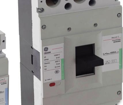
4 Record* Moulded case circuit breaker Low-Voltage Moulded ase ircuit reaker (M) pplicable scope Record* has a rated insulation voltage of 1000V which is suitable for low-voltage distribution and motor protection application. vailable in five (5) breaker frame sizes with rated current from 16 up to 800. pplication Record* can be used for installation in the industrial segment, factories, residential and commercial sectors. The breakers are suitable to be installed in enclosures and switchboards. Features The Record* breakers are compact and have high breaking capacity. They can also be installed vertically or horizontally. ccessories are standardized for easy installation. The circuit breaker is compliant with IE standard. Standard operating conditions ltitude: Up to 2000m above sea level. mbient temperature: -5 ±40 (Operation of continuous 24 hours average not more than +35 ). Other atmospheric conditions: Salt spray, oil mist (moderate) & mold. Installation category of circuit breaker connecting to the main circuit: ategory III. Pollution level: Not exceeding class 3. The RecordTM circuit breakers should be utilised under normal ambient operating conditions. The breakers are not suitable to be installed in a potentially explosive and corrosive environment such as explosive chemical, corrosive gas and dust exposure..2
 1000 1000 1000 1000 1000 Rated insulation impulse withstand voltage Uimp (Kilovolt) 8 8 8")
 400V 35 50 35 50 35 50 70 35 50 70 50 70 Rated service breaking capacity Ics (k) 400V")

 Mechanical 12500 12500 8000 8000 5000 Electrical (full current) 4000 5000 2500 2500 2500 Line thermal Trip unit magnetic trip")
 mm Weight (kg) Fixed Plug-in Front connection Rear connection Fixed front connect. 3P Fixed front connect.")
5 Moulded ase ircuit reaker - thermal magnetic IE Standard ircuit breaker Types S N S N S N H S N H N H Number of poles 3P/4P 3P/4P 3P/4P 3P/4P 3P/4P Rated insulation voltage Ui (Volts) Rated insulation impulse withstand voltage Uimp (Kilovolt) Rated operating voltage (50/60Hz) Volts Line protection device ategory of use Suitable as isolator Yes Rated current Ith=Ie at Rated ultimate breaking capacity Icu (k) 400V Rated service breaking capacity Ics (k) 400V Endurance (O cycle) Mechanical Electrical (full current) Line thermal Trip unit magnetic trip Fixed Motor magnetic only trip Installation (1) ircuit breaker Types S N S N S N H S N H N H Introduction Installation method onnection method Dimension (w x h x d) mm Weight (kg) Fixed Plug-in Front connection Rear connection Fixed front connect. 3P Fixed front connect. 3P S 92*150*100 N 92*150*118 S 105*150*122.5 N 105*150*139.5 Yes Yes 150*257* *270* *280*162 4P 122*150* *150* *257* *240* *280*162 S 1.34 N 1.71 S 1.84 N P ) The circuit breaker, only allows upper incoming and lower outgoing, no reverse connection. 2) The interphase barrier is standard configuration of the circuit breaker..3
 1000 1000 1000 1000 Rated insulation impulse withstand voltage Uimp (Kilovolt) 8 8 8 8 Rated operating voltage Volts (50/60Hz) 400 400 400 400")
 400V 37.5 37.5 52.")
6 Record* Moulded case circuit breaker Moulded ase ircuit reaker - thermal magnetic and leakage IE Standard ircuit breaker E125 E250 E400 E630 Type N N H H Number of poles Number of poles 3P/4P 3P/4P 3P/4P 3P/4P Rated insulation voltage Ui (Volts) Rated insulation impulse withstand voltage Uimp (Kilovolt) Rated operating voltage Volts (50/60Hz) Line protection device ategory of use Suitable as isolator Yes Rated current Ith=Ie at Rated ultimate short-circuit breaking capacity Icu (k) 400V Rated service short-circuit breaking capacity Ics (k) 400V Endurance (O cycle) Mechanical Electrical (full current) Line thermal magnetic trip Motor magnetic Fixed only trip Rated residual operating current I no Rated residual non-operating current I no Rated residual short-circuit making current I m Installation (1) Delay/non-delay 100/300/500 (m) 300/500/1000 (m) 1/2 I no 1/4 I no 300/500/1000 (m) 1 / 3 / 10 / 30 () ircuit breaker E125 E250 E400 E630 Type N N H H Installation method Fixed Yes Plug-in No Yes onnection method Front connection Rear connection Yes Dimension (w x h x d) mm Fixed front connect. 3P 150*92*87 150*105* *257* *280*162 4P 150*122*87 150*142* *257* *280*162 Weight (kg) Fixed front connect. 3P P ) For the circuit breaker, only top incoming and bottom outgoing are allowed, reverse connection is not permitted. 2) The interphase barrier is standard configuration of the circuit breaker..4
7 General specifications Moulded ase ircuit reaker model explanation Record series circuit breaker model quick selection table Record series circuit breaker with leakage protection model quick selection table Product specification Product specification ircuit breaker E ircuit breaker with leakage protection Frame level Frame level reaking capacity reaking capacity Number of poles Number of poles 125 S = 35K 3 = 3P 250 N = 50K 4 = 4 pole 4 trips 400 H = 70K R = 4 pole 3 trips Trip Rated current Protection against earth leakage current 125 S = 35K 3 = 3P TM Line thermal with delay - without alarm output 250 N = 50K 4 = 4 pole 4 trip magnetic without delay - without alarm output 400 H = 70K R = 4 pole 3 trips protection E with delay - with alarm output 630 M Magnetic only protection F without delay - with alarm output TM Trip Line thermal magnetic protection 630 M Magnetic only 800 protection For example: 125N3TM125 series circuit breaker Frame K 3P Line thermal magnetic trip 125 Rated current General specifications For example: E125N3TM016 E series circuit breaker with leakage protection Frame K - 3P Line thermal magnetic trip 16 Leakage delay type Record* - General specifications Rated current K 3P - 50K 3P 4P K 3P - 50K 3P 4P 35K 3P K 3P - 70K 3P 4P 35K 3P K 3P - 70K 3P 4P K 3P - 70K 3P 4P Rated current E125 50K 3P 4P E250 50K 3P 4P E400 70K 3P 4P E630 70K 3P 4P.5

8
9 Just rely on us
10
11 Record*.2 frame.6 E frame.12 ccessories.16 uxiliary contact - suitable for /E.16 larm contact.17 Under-voltage release.18 Electrical operators.19 Rotary handle.19 onnections for Ms / E.19 Operation and maintenance Introduction and specifications Order codes Dimensions and applications Numerical index.1
12 Record* frame 125 Thermal magnetic protection 3 Poles 4 Poles 4 Trips 4 Poles 3 Trips In () at. no. Ref. no. at. no. Ref. no. at. no. Ref. no. Thermal magnetic type 35k S 50k N S3TM S3TM S3TM S3TM S3TM S3TM S3TM S3TM S3TM S3TM N3TM N4TM NRTM N3TM N4TM NRTM N3TM N4TM NRTM N3TM N4TM NRTM N3TM N4TM NRTM N3TM N4TM NRTM N3TM N4TM NRTM N3TM N4TM NRTM N3TM N4TM NRTM N3TM N4TM NRTM frame 250 Thermal magnetic protection 35k S 3 Poles 4 Poles 4 Trips 4 Poles 3 Trips In () at. no. Ref. no. at. no. Ref. no. at. no. Ref. no S3TM S3TM S3TM S3TM S3TM S3TM S3TM S3TM k N N3TM N4TM NRTM N3TM N4TM NRTM N3TM N4TM NRTM N3TM N4TM NRTM N3TM N4TM NRTM N3TM N4TM NRTM N3TM N4TM NRTM N3TM N4TM NRTM
13 frame 400 Thermal magnetic protection 3 Poles 4 Poles 4 Trips 4 Poles 3 Trips In () at. no. Ref. no. at. no. Ref. no. at. no. Ref. no. 35k S S3TM S3TM S3TM S3TM S3TM k N 70K H N3TM N3TM N3TM N3TM N3TM H3TM H4TM HRTM H3TM H4TM HRTM H3TM H4TM HRTM H3TM H4TM HRTM H3TM H4TM HRTM Order codes frame 630 Thermal magnetic protection 35k S 50k N 70K H 3 Poles 4 Poles 4 Trips 4 Poles 3 Trips In () at. no. Ref. no. at. no. Ref. no. at. no. Ref. no S3TM S3TM S3TM N3TM N3TM N3TM H3TM H4TM HRTM H3TM H4TM HRTM H3TM H4TM HRTM frame 800 Thermal magnetic protection 3 Poles 4 Poles 4 Trips 4 Poles 3 Trips In () at. no. Ref. no. at. no. Ref. no. at. no. Ref. no. 50k N N3TM N3TM N3TM K H H3TM H4TM HRTM H3TM H4TM HRTM H3TM H4TM HRTM
14 Record* frame 125 Magnetic only protection 3 Poles 4 Poles 4 Trips 4 Poles 3 Trips In () at. no. Ref. no. at. no. Ref. no. at. no. Ref. no. Thermal magnetic type 35k S 50k N S3M S3M S3M S3M S3M S3M S3M S3M S3M S3M N3M N4M NRM N3M N4M NRM N3M N4M NRM N3M N4M NRM N3M N4M NRM N3M N4M NRM N3M N4M NRM N3M N4M NRM N3M N4M NRM N3M N4M NRM frame 250 Magnetic only protection 35k S 3 Poles 4 Poles 4 Trips 4 Poles 3 Trips In () at. no. Ref. no. at. no. Ref. no. at. no. Ref. no S3M S3M S3M S3M S3M S3M S3M S3M k N N3M N4M NRM N3M N4M NRM N3M N4M NRM N3M N4M NRM N3M N4M NRM N3M N4M NRM N3M N4M NRM N3M N4M NRM
15 frame 400 Magnetic only protection 3 Poles 4 Poles 4 Trips 4 Poles 3 Trips In () at. no. Ref. no. at. no. Ref. no. at. no. Ref. no. 35k S S3M S3M S3M S3M S3M k N 70K H N3M N3M N3M N3M N3M H3M H4M HRM H3M H4M HRM H3M H4M HRM H3M H4M HRM H3M H4M HRM Order codes frame 630 Magnetic only protection 35k S 50k N 70K H 3 Poles 4 Poles 4 Trips 4 Poles 3 Trips In () at. no. Ref. no. at. no. Ref. no. at. no. Ref. no S3M S3M S3M N3M N3M N3M H3M H4M HRM H3M H4M HRM H3M H4M HRM
16 Record* E frame E125 Thermal-magnetic protection 3 Poles 4 Poles 4 Trips 4 Poles 3 Trips In () at. no. Ref. no. at. no. Ref. no. at. no. Ref. no. Leakage type 50k N With delayed residual current device 16 E125N3TM E125N4TM E125NRTM E125N3TM E125N4TM E125NRTM E125N3TM E125N4TM E125NRTM E125N3TM E125N4TM E125NRTM E125N3TM E125N4TM E125NRTM E125N3TM E125N4TM E125NRTM E125N3TM E125N4TM E125NRTM E125N3TM E125N4TM E125NRTM E125N3TM E125N4TM E125NRTM E125N3TM E125N4TM E125NRTM With residual current device 16 E125N3TM E125N4TM E125NRTM E125N3TM E125N4TM E125NRTM E125N3TM E125N4TM E125NRTM E125N3TM E125N4TM E125NRTM E125N3TM E125N4TM E125NRTM E125N3TM E125N4TM E125NRTM E125N3TM E125N4TM E125NRTM E125N3TM E125N4TM E125NRTM E125N3TM E125N4TM E125NRTM E125N3TM E125N4TM E125NRTM With delayed residual current device and alarm 16 E125N3TM016E E125N4TM016E E125NRTM016E E125N3TM020E E125N4TM020E E125NRTM020E E125N3TM025E E125N4TM025E E125NRTM025E E125N3TM032E E125N4TM032E E125NRTM032E E125N3TM040E E125N4TM040E E125NRTM040E E125N3TM050E E125N4TM050E E125NRTM050E E125N3TM063E E125N4TM063E E125NRTM063E E125N3TM080E E125N4TM080E E125NRTM080E E125N3TM100E E125N4TM100E E125NRTM100E E125N3TM125E E125N4TM125E E125NRTM125E With residual current device and alarm 16 E125N3TM016F E125N4TM016F E125NRTM016F E125N3TM020F E125N4TM020F E125NRTM020F E125N3TM025F E125N4TM025F E125NRTM025F E125N3TM032F E125N4TM032F E125NRTM032F E125N3TM040F E125N4TM040F E125NRTM040F E125N3TM050F E125N4TM050F E125NRTM050F E125N3TM063F E125N4TM063F E125NRTM063F E125N3TM080F E125N4TM080F E125NRTM080F E125N3TM100F E125N4TM100F E125NRTM100F E125N3TM125F E125N4TM125F E125NRTM125F
17 E frame E250 Thermal-magnetic protection 3 Poles 4 Poles 4 Trips 4 Poles 3 Trips In () at. no. Ref. no. at. no. Ref. no. at. no. Ref. no. With delayed residual current device 100 E250N3TM E250N4TM E250NRTM E250N3TM E250N4TM E250NRTM E250N3TM E250N4TM E250NRTM E250N3TM E250N4TM E250NRTM E250N3TM E250N4TM E250NRTM E250N3TM E250N4TM E250NRTM E250N3TM E250N4TM E250NRTM E250N3TM E250N4TM E250NRTM k N With residual current device 100 E250N3TM E250N4TM E250NRTM E250N3TM E250N4TM E250NRTM E250N3TM E250N4TM E250NRTM E250N3TM E250N4TM E250NRTM E250N3TM E250N4TM E250NRTM E250N3TM E250N4TM E250NRTM E250N3TM E250N4TM E250NRTM E250N3TM E250N4TM E250NRTM With delayed residual current device and alarm 100 E250N3TM100E E250N4TM100E E250NRTM100E E250N3TM125E E250N4TM125E E250NRTM125E E250N3TM140E E250N4TM140E E250NRTM140E E250N3TM160E E250N4TM160E E250NRTM160E E250N3TM180E E250N4TM180E E250NRTM180E E250N3TM200E E250N4TM200E E250NRTM200E E250N3TM225E E250N4TM225E E250NRTM225E E250N3TM250E E250N4TM250E E250NRTM250E Order codes With delayed residual current device and alarm 100 E250N3TM100F E250N4TM100F E250N4TM100F E250N3TM125F E250N4TM125F E250N4TM125F E250N3TM140F E250N4TM140F E250N4TM140F E250N3TM160F E250N4TM160F E250N4TM160F E250N3TM180F E250N4TM180F E250N4TM180F E250N3TM200F E250N4TM200F E250N4TM200F E250N3TM225F E250N4TM225F E250N4TM225F E250N3TM250F E250N4TM250F E250N4TM250F
18 Record* E frame E400 Thermal-magnetic protection 3 Poles 4 Poles 4 Trips 4 Poles 3 Trips In () at. no. Ref. no. at. no. Ref. no. at. no. Ref. no. With delayed residual current device 225 E400H3TM E400H4TM E400HRTM E400H3TM E400H4TM E400HRTM E400H3TM E400H4TM E400HRTM E400H3TM E400H4TM E400HRTM E400H3TM E400H4TM E400HRTM Leakage type 70k H With residual current device 225 E400H3TM E400H4TM E400HRTM E400H3TM E400H4TM E400HRTM E400H3TM E400H4TM E400HRTM E400H3TM E400H4TM E400HRTM E400H3TM E400H4TM E400HRTM With delayed residual current device and alarm 225 E400H3TM225E E400H4TM225E E400HRTM225E E400H3TM250E E400H4TM250E E400HRTM250E E400H3TM315E E400H4TM315E E400HRTM315E E400H3TM350E E400H4TM350E E400HRTM350E E400H3TM400E E400H4TM400E E400HRTM400E With residual current device and alarm 225 E400H3TM225F E400H4TM225F E400HRTM225F E400H3TM250F E400H4TM250F E400HRTM250F E400H3TM315F E400H4TM315F E400HRTM315F E400H3TM350F E400H4TM350F E400HRTM350F E400H3TM400F E400H4TM400F E400HRTM400F E frame E630 Thermal-magnetic protection 3 Poles 4 Poles 4 Trips 4 Poles 3 Trips In () at. no. Ref. no. at. no. Ref. no. at. no. Ref. no. With delayed residual current device 400 E630H3TM E630H4TM E630HRTM E630H3TM E630H4TM E630HRTM E630H3TM E630H4TM E630HRTM k H With residual current device 400 E630H3TM E630H4TM E630HRTM E630H3TM E630H4TM E630HRTM E630H3TM E630H4TM E630HRTM With delayed residual current device and alarm 400 E630H3TM400E E630H4TM400E E630HRTM400E E630H3TM500E E630H4TM500E E630HRTM500E E630H3TM630E E630H4TM630E E630HRTM630E With residual current device and alarm 400 E630H3TM400F E630H4TM400F E630HRTM400F E630H3TM500F E630H4TM500F E630HRTM500F E630H3TM630F E630H4TM630F E630HRTM630F
19 E frame E125 Magnetic-only protection 3 Poles 4 Poles 4 Trips 4 Poles 3 Trips In () at. no. Ref. no. at. no. Ref. no. at. no. Ref. no. 50k N With delayed residual current device 16 E125N3M E125N4M E125NRM E125N3M E125N4M E125NRM E125N3M E125N4M E125NRM E125N3M E125N4M E125NRM E125N3M E125N4M E125NRM E125N3M E125N4M E125NRM E125N3M E125N4M E125NRM E125N3M E125N4M E125NRM E125N3M E125N4M E125NRM E125N3M E125N4M E125NRM With residual current device 16 E125N3M E125N4M E125NRM E125N3M E125N4M E125NRM E125N3M E125N4M E125NRM E125N3M E125N4M E125NRM E125N3M E125N4M E125NRM E125N3M E125N4M E125NRM E125N3M E125N4M E125NRM E125N3M E125N4M E125NRM E125N3M E125N4M E125NRM E125N3M E125N4M E125NRM With delayed residual current device and alarm 16 E125N3M016E E125N4M016E E125NRM016E E125N3M020E E125N4M020E E125NRM020E E125N3M025E E125N4M025E E125NRM025E E125N3M032E E125N4M032E E125NRM032E E125N3M040E E125N4M040E E125NRM040E E125N3M050E E125N4M050E E125NRM050E E125N3M063E E125N4M063E E125NRM063E E125N3M080E E125N4M080E E125NRM080E E125N3M100E E125N4M100E E125NRM100E E125N3M125E E125N4M125E E125NRM125E Order codes With residual current device and alarm 16 E125N3M016F E125N4M016F E125NRM016F E125N3M020F E125N4M020F E125NRM020F E125N3M025F E125N4M025F E125NRM025F E125N3M032F E125N4M032F E125NRM032F E125N3M040F E125N4M040F E125NRM040F E125N3M050F E125N4M050F E125NRM050F E125N3M063F E125N4M063F E125NRM063F E125N3M080F E125N4M080F E125NRM080F E125N3M100F E125N4M100F E125NRM100F E125N3M125F E125N4M125F E125NRM125F
20 Record* E frame E125 Magnetic-only protection 3 Poles 4 Poles 4 Trips 4 Poles 3 Trips In () at. no. Ref. no. at. no. Ref. no. at. no. Ref. no. With delayed residual current device 100 E250N3M E250N4M E250NRM E250N3M E250N4M E250NRM E250N3M E250N4M E250NRM E250N3M E250N4M E250NRM E250N3M E250N4M E250NRM E250N3M E250N4M E250NRM E250N3M E250N4M E250NRM E250N3M E250N4M E250NRM Leakage type 50k N With residual current device 100 E250N3M E250N4M E250NRM E250N3M E250N4M E250NRM E250N3M E250N4M E250NRM E250N3M E250N4M E250NRM E250N3M E250N4M E250NRM E250N3M E250N4M E250NRM E250N3M E250N4M E250NRM E250N3M E250N4M E250NRM With delayed residual current device and alarm 100 E250N3M100E E250N4M100E E250NRM100E E250N3M125E E250N4M125E E250NRM125E E250N3M140E E250N4M140E E250NRM140E E250N3M160E E250N4M160E E250NRM160E E250N3M180E E250N4M180E E250NRM180E E250N3M200E E250N4M200E E250NRM200E E250N3M225E E250N4M225E E250NRM225E E250N3M250E E250N4M250E E250NRM250E With residual current device and alarm 100 E250N3M100F E250N4M100F E250NRM100F E250N3M125F E250N4M125F E250NRM125F E250N3M140F E250N4M140F E250NRM140F E250N3M160F E250N4M160F E250NRM160F E250N3M180F E250N4M180F E250NRM180F E250N3M200F E250N4M200F E250NRM200F E250N3M225F E250N4M225F E250NRM225F E250N3M250F E250N4M250F E250NRM250F
21 E frame E400 Magnetic-only protection 3 Poles 4 Poles 4 Trips 4 Poles 3 Trips In () at. no. Ref. no. at. no. Ref. no. at. no. Ref. no. With delayed residual current device 225 E400H3M E400H4M E400HRM E400H3M E400H4M E400HRM E400H3M E400H4M E400HRM E400H3M E400H4M E400HRM E400H3M E400H4M E400HRM k H With residual current device 225 E400H3M E400H4M E400HRM E400H3M E400H4M E400HRM E400H3M E400H4M E400HRM E400H3M E400H4M E400HRM E400H3M E400H4M E400HRM With delayed residual current device and alarm 225 E400H3M225E E400H4M225E E400HRM225E E400H3M250E E400H4M250E E400HRM250E E400H3M315E E400H4M315E E400HRM315E E400H3M350E E400H4M350E E400HRM350E E400H3M400E E400H4M400E E400HRM400E With residual current device and alarm 225 E400H3M225F E400H4M225F E400HRM225F E400H3M250F E400H4M250F E400HRM250F E400H3M315F E400H4M315F E400HRM315F E400H3M350F E400H4M350F E400HRM350F E400H3M400F E400H4M400F E400HRM400F E frame E630 Magnetic-only protection 3 Poles 4 Poles 4 Trips 4 Poles 3 Trips In () at. no. Ref. no. at. no. Ref. no. at. no. Ref. no. Order codes With delayed residual current device 400 E630H3M E630H4M E630HRM E630H3M E630H4M E630HRM E630H3M E630H4M E630HRM k H With residual current device 400 E630H3M E630H4M E630HRM E630H3M E630H4M E630HRM E630H3M E630H4M E630HRM With delayed residual current device and alarm 400 E630H3M400E E630H4M400E E630HRM400E E630H3M500E E630H4M500E E630HRM500E E630H3M630E E630H4M630E E630HRM630E With residual current device and alarm 400 E630H3M400F E630H4M400F E630HRM400F E630H3M500F E630H4M500F E630HRM500F E630H3M630F E630H4M630F E630HRM630F
22 Record* ccessories Single auxiliary contact For breaker type at. no. Ref. no. at. no. Ref. no. Single auxiliary contact LEFT RIGHT 125/E FS1L FS1R /E FS1L FS1R /630/800 - E400/ FS1L FS1R Dual auxiliary contact ccessories Dual auxiliary contact: LEFT RIGHT 125/E FS2L FS2R /E FS2L FS2R /630/800 - E400/ FS2L FS2R Single alarm contact LEFT RIGHT 125/E ML MR /E ML MR /630/800 - E400/ ML MR uxiliary and larm contacts module Single alarm contact LEFT RIGHT 125/E FST1L FST1R /E FST1L FST1R Dual alarm contact 400/630/800 - E400/ FST2L FST2R Shunt release Shunt release LEFT RIGHT 125/E V E125SHTL SHTR /E V E250SHTL SHTR /630/800 - E400/ V E400SHTL SHTR Under-voltage release Under-voltage release LEFT 125/E V 125UVRN /E V 125UVR /E V 250UVRN /E V 250UVR /630 - E V 400UVRN /630 - E V 400UVR /E V 800UVRN /E V 800UVR N Rotary handle Rotary handle 125/E NRF /E NRF /E400 3P 400NRF /E400 4P 400NRF NRF13 630NRF NRF14 630NRF NRF13 800NRF NRF14 800NRF N.12 Notes: The last 2 digits of the product model 1. stands for round cover plate, 2. 3P stands for 3Poles breaker mounting, 3. 4P stands for 4Poles breaker mounting
23 ccessories Electric operating mechanism For breaker type at. no. Ref. no. 125/E V 125FMFS /E V 250FMFS /E V 400FMF V 630FMF /E V 800FMF Extended spreader For breaker type at. no. Ref. no. at. no. Ref. no. Spreader busbar: 3P 4P 125/E SS SS /E SS SS /E SS SS SS SS /E SS SS Rear connections Order codes For breaker type at. no. Ref. no. at. no. Ref. no. Rear terminal: 3P 4P 125/E R R /E R R /E R R R R /E R R Plug-in kit - Front connections For breaker type at. no. Ref. no. at. no. Ref. no. Front connections: 3P 4P FMFS FMFS N 400/E FMF FMF Plug-in kit - Rear connections For breaker type at. no. Ref. no. at. no. Ref. no. Rear connections: 3P 4P DDF DDF DDF DDF /E DDF DDF DDF DDF /E DDF DDF
24 Record* ccessories ode ccessory 3P 4P 3P 4P 3P 4P 3P 4P 3P 4P 00 None Shunt release Low voltage Ms - E 20 Dual auxiliary contact 21 Single auxiliary contact 30 Under-voltage release 40 Shunt release + dual auxiliary contacts 41 Shunt release + single auxiliary contact 50 Shunt release + undervoltage release 60 Two groups of dual auxiliary contact 61 Two groups of single auxiliary contact 62 Double auxiliary cont. + single auxiliary contact 70 Under-voltage release + dual auxiliary contact 71 Under-voltage release + single auxiliary contact 08 larm contact 18 Shunt release + alarm contact 28 Dual auxiliary contact + alarm contact 38 Under-voltage release + alarm contact 48 Shunt release, single auxiliary + alarm contact Single auxiliary alarm contact Dual auxiliary contact + single auxiliary alarm contact 78 Under-voltage release, single auxiliary + alarm contact - Handle Legend Single auxiliary contact Left mounting Right mounting Dual auxiliary contact larm contact Shunt release Undervoltage release Single auxiliary alarm contact.14
25 ccessories - E ode ccessory 10 Shunt release P 4P 4P 4P 20 Dual auxiliary contact 21 Single auxiliary contact 30 Under-voltage release 40 Shunt release + dual auxiliary contacts 41 Shunt release + single auxiliary contact 60 Two groups of dual auxiliary contact 61 Two groups of single auxiliary contact 62 Double auxiliary cont. + single auxiliary contact 70 Under-voltage release + dual auxiliary contact 71 Under-voltage release + single auxiliary contact 08 larm contact 28 Dual auxiliary contact + alarm contact 58 Under-voltage release + alarm contact Order codes 68 Dual auxiliary contact + single auxiliary alarm contact Handle Legend Single auxiliary contact Left mounting Right mounting Dual auxiliary contact larm contact Shunt release Undervoltage release Single auxiliary alarm contact Note: E series 3P product could only use left-mounted single accessory..15
26 Record* Low voltage Ms / E uxiliary contact - suitable for /E uxiliary contacts and its combination The circuit breaker in "open" or "tripped" position 1 - haracteristics of auxiliary contacts ircuit breaker frame Rated thermal current Ith urrent consumption at 400V /E Dual auxiliary contact Single auxiliary contact Technical parameters of the auxiliary contact - suitable for /E uxiliary contact wiring diagram F11 F14 F12 F24 F22 F14 F12 F14 Power supply Normally open F11 F21 F11 F12 Normally closed 2 - Electrical endurance ategory of use Making reaking Frequency Operating frequency (times/hour) Response time I/Ie U/Ue cosφ I/Ie U/Ue cosφ I/Ie U/Ue cosφ s D Pe 1 1 6Pe T Operating threshold ategory of use Making reaking Frequency Operating frequency (times/hour) Response time I/Ie U/Ue cosφ I/Ie U/Ue cosφ I/Ie U/Ue cosφ s D Pe Pe T0.95 larm contact uxiliary contact wiring diagram larm contact Ue=220V, Ith=3 ircuit breaker in "open" and "close" position ircuit breaker in "tripped" position When the circuit breaker is closed and opened normally, the contact does not work. The contact changes its normal state only after tripping (or fault trip) occurs, with open state turning into closed, and closed state into open. fter the circuit breaker is reset, the contact returns to its original position..16
27 Under-voltage release The under-voltage release opens the circuit breaker when supply voltage drops to a value below 35% to70% to its rated voltage. When the power supply is equal or greater than 85% of the rated voltage, closing of the circuit breaker is allowed. haracteristics reaker type urrent consumption (m) Power consumption (W) ontrol circuit: 50/60Hz 230V 400V Note: the undervoltage must be be energized so that the circuit breaker ccan be reset and closed. Wiring diagram 400V 50/60Hz 230V 50/60Hz 400V 50/60Hz cosφ 125/E /E /E /E P1 P2 Power input ccessories Shunt release The shunt release will trip the circuit breaker when the rated control voltage is between 70% and 110%. Wiring diagram urrent consumption of 1 Recommended diagram for D power supply Power input haracteristics reaker type urrent consumption (m) Power consumption (W) 400V 230V D 220V D 24V 400V 230V D 220V D 24V 125/E /E /E /E
28 Record* Electrical operators The wiring diagram of the external accessories of the breaker is displayed in the dotted box. Wiring diagram Low voltage Ms / E Power supply P1 P2 S1 S2 S4 External power supply M ontrol circuit S1 (closed) S2 (opened) Description S1, S2: Push-but ton (provided by user) : Wiring terminal P1, P2: External power supply Specifications: 50/60Hz, 230V, 400V D 24V, 100V, 220V haracteristics reaker type Operating current () H Operating power (W) Life span Height of the operator H (mm) 125/E /E /E /E
29 Rotary handle - S1- Dimensions H Ø5.5 Ø36 Note: Handle cover is round ircuit breaker 24 D MIN=50mm Mounting method and external dimension of rotary handle Rotary handle reaker Dimensions (mm) Mounting method H Metal 3P 4P S /E S /E S /E Vertical S S /E or ccessories Note: Standard depth is 150mm onnections for Ms / E onnection of main terminals Rated urrent () ross section of cable (mm 2 ) onnection of insulated busbar and cables Rated urrent () ross section of cable Dimension of copper bar Quantity ross section area (mm 2 ) Quantity Min. dimension (mm 2 ) , (1) Note 1: Select a suitable connection accessory to the breaker termination and wiring requirement. Note 2: the copper bar termination to be connected with the proper spreader busbar. Operation and maintenance The features and accessories of the circuit breaker are set by the manufacturer. Do not adjust them during operation. The breakers are designed to isolate, switch and protect low-voltage distribution circuits. The trip units have been designed with the trip unit ratings indicated in mperes. To prevent unauthorized tampering of the breaker setting, each trip unit comes with a transparent, tamper-free cover. The circuit breakers are calibrated in the factory and no further calibration is required. The time current curves of the breakers are published in this catalogue..19

30
31 Just rely on us
32 Record* Low voltage Ms / E.22
33 Record* Power connections and installation (S, N) (S, N) (S, N, H) (S, N, H) (N, H).7 E Power connections and installation E.8 Installation with plug-in Introduction and specifications pplications.12 haracteristics and curves Order codes Dimensions and applications Numerical index.1
34 Power connections and installation Dimensions Power connections and installation (S, N) Front connection (3P, 4P) Mounting hole dimensions for front connection Type H H1 125S N Rear connection (3P, 4P) Mounting hole dimensions for rear connection.2
35 Dimensions Power connections and installation (S, N) Front connection (3P, 4P) Dimensions and applications Mounting hole dimensions for front connection Type H H1 250S N 250 4P Rear connection (3P, 4P) Mounting hole dimensions for rear connection.3
36 Record* Power connections and installation Dimensions Power connections and installation (S, N, H) Front connection (3P, 4P) Mounting hole dimensions for front connection Rear connection (3P, 4P) Mounting hole dimensions for rear connection.4
37 Dimensions Power connections and installation (S, N, H) Front connection (3P, 4P) Mounting hole dimensions for front connection Dimensions and applications Rear connection (3P, 4P) Mounting hole dimensions for rear connection.5
 Mounting hole dimensions for front connection Rear connection (3P, 4P) Mounting hole dimensions for rear")
38 Record* Power connections and installation Dimensions Power connections and installation (N, H) Front connection (3P, 4P) Mounting hole dimensions for front connection Rear connection (3P, 4P) Mounting hole dimensions for rear connection.6
 Mounting method W L2 M H1 H2 H3 H4 3P 4P 1 Ø 1 E125 225 92 122 50 8 24 87 118-60 204 4.5 30 E250 252 107 142 65 8 24 105.5 139.5-70 213 4.")
39 Dimensions Power connections and installation -E Front connection (3P, 4P) Mounting hole dimensions for front connection Dimensions and applications Overall dimension and mounting dimension reaker type L1 Manual mounting dimension (mm) Mounting method W L2 M H1 H2 H3 H4 3P 4P 1 Ø 1 E E E E Overall dimension of cover reaker type D E F E E E E
40 Record* Dimensions Power connections and installation Installation with plug-in Through back plate reaker type L L1 L2 d D E H1 H /E /E Note: For 4 Pole breaker, dimension of E is added to, L2, and D..8
41 Dimensions Installation with plug-in Through panel Dimensions and applications reaker type L1 L2 d E /E /E Note: For 4 Pole breakers 1.reaker frame 250 and below, dimension of E is added to, L2 2.reaker frame 400 and above, dimension of E is added. Dimension of remain the same..9
42 Record* Dimensions Power connections and installation Installation with plug-in On back plate reaker type L1 E d M H h M M /E M M /E M
43 Dimensions Installation with plug-in On DIN-rail Dimensions and applications reaker type E /E /E Note: For 4 Pole breaker E is additional dimension to..11
44 Record* pplications Performance Ms - Series Rated current () Thermal release (ambient temperature +40 ) 1.05In (cold state) non-tripping time (h) 1.3In (hot state) tripping time (h) Tripping current of magnetic release () 10 In In ( 1±20%)* Line thermal magnetic 63<In In ( 1±20%) protection for the circuit 10 In 800 Heat dissipation reaker type 1.0In (cold state) non-tripping time (h) 2 2 Max. rated current () 1.2In (hot state) tripping time (h) 12In ( 1±20%) Heat dissipation (W) - 3P Notes Provides protection for the motor Front and rear connection Plug-in front connection Plug-in rear connection 125 (S, N)- (16-25) (S, N) - (32-100) (S, N) - (125) (S, N) - ( ) (S, N) - (250) (S, N, H) - ( ) (S, N, H) - ( ) (N, H) - ( ) Derating factor mbient temperature reaker type Note: The derating factors above are measured under the rated current of the breaker frame..12


45 pplications urrent temperature characteristic - time/current characteristic 125 current temperature characteristic 125 S/N time/current characteristic curve pplications 250 current temperature characteristic 250 S/N time/current characteristic curve 400 current temperature characteristic 400 S/N/H time/current characteristic curve.13


46 Record* pplications - urrent temperature characteristic - time/current characteristic 630 current temperature characteristic 630 S/N/H time/current characteristic curve Ms - Series 800 current temperature characteristic 800 N/H time/current characteristic curve.14
 operating time (h) Operating current of electromagnetic trip () 10 In 63 1 1 10In ( 1±20%) 63<In 800 2 2 10In ( 1±20%) 16 In 800 1.")
47 pplications E Operating performance of trip Rated current () Thermal trip (ambient temperature +40 ) 1.05In (cold state) non-operating time (h) 1.3In (hot state) operating time (h) Operating current of electromagnetic trip () 10 In In ( 1±20%) 63<In In ( 1±20%) 16 In In (cold state) non-operating time (h) 2 2 Remarks Power distribution type 1.2In (hot state) operating time (h) 12In ( 1±20%) Motor protection type Reference table of power loss reaker type Making current () Total power loss of the four poles (W) Front and rear connection E125 Direct heating type (16-25) E125 Indirect heating type (32-125) E E E pplications Derating factor of change of ambient temperaturederatin Temperature Derating factor (In) reaker type E E E E haracteristic curve of circuit breaker - E E125 current temperature characteristic E125 time/current characteristic curve.15


48 Record* pplications E - urrent temperature characteristic - time/current characteristic E250 current temperature characteristic E250 time/current characteristic curve Ms - leakage type Operating time t/s E400 current temperature characteristic E400 time/current characteristic curve Operating time t/s E630 current temperature characteristic E630 time/current characteristic curve Operating time t/s.16
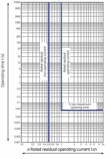
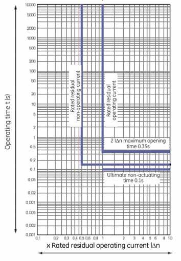
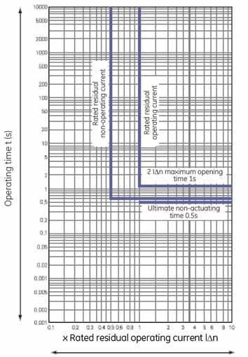
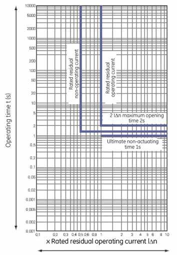
49 pplications haracteristic curve of residual current protection of circuit breaker pplications.17

 0.5/1.15/2.15 0.35/1/2 0.25/0.9/1.")


50 Record* haracteristic curve of residual current protection of circuit breaker Residual current operating time Ms - leakage type mbient temperature Residual current IΔt 2 IΔn 5 IΔn 10 IΔn Non-delay Maximum opening time (s) Delay Maximum opening time (s) 0.5/1.15/ /1/2 0.25/0.9/ /0.9/1.9 Ultimate non-actuating time t (s) - 0.1/0.5/1 - - Residual current settings rotary switch schematic E125/250 E400 E125/250 E400/630 E630 Wiring diagram of alarm non-tripping module Note: P1, P2 are the terminal blocks of normally closed contact P3, P4 are the terminal blocks of normally open contact P5, P6 are the terminal blocks of 230V power supply.18
51 Record* Introduction and specifications Order codes.2 Numerical index by reference number.5 Numerical index by catalogue number Dimensions and applications Numerical index.1
52 Record* y reference number Numerical index Ref. no. at. no. Page E250N3M E250N3M E250N3M100E E250N3M100F E250N3M E250N3M E250N3M125E E250N3M125F E250N3M E250N3M E250N3M140E E250N3M140F E250N3M E250N3M E250N3M160E E250N3M160F E250N3M E250N3M E250N3M180E E250N3M180F E250N3M E250N3M E250N3M200E E250N3M200F E250N3M E250N3M E250N3M225E E250N3M225F E250N3M E250N3M E250N3M250E E250N3M250F E250N4M E250N4M E250N4M100E E250N4M100F E250N4M E250N4M E250N4M125E E250N4M125F E250N4M E250N4M E250N4M140E E250N4M140F E250N4M E250N4M E250N4M160E E250N4M160F E250N4M E250N4M E250N4M180E E250N4M180F E250N4M E250N4M E250N4M200E E250N4M200F E250N4M E250N4M E250N4M225E E250N4M225F E250N4M E250N4M E250N4M250E E250N4M250F E250NRM E250NRM E250NRM100E E250NRM100F E250NRM E250NRM E250NRM125E E250NRM125F E250NRM E250NRM E250NRM140E E250NRM140F E250NRM E250NRM E250NRM160E E250NRM160F E250NRM E250NRM E250NRM180E E250NRM180F E250NRM E250NRM E250NRM200E E250NRM200F.10 Ref. no. at. no. Page E250NRM E250NRM E250NRM225E E250NRM225F E250NRM E250NRM E250NRM250E E250NRM250F E400H3M E400H3M E400H3M225E E400H3M225F E400H3M E400H3M E400H3M250E E400H3M250F E400H3M E400H3M E400H3M315E E400H3M315F E400H3M E400H3M E400H3M350E E400H3M350F E400H3M E400H3M E400H3M400E E400H3M400F E400H4M E400H4M E400H4M225E E400H4M225F E400H4M E400H4M E400H4M250E E400H4M250F E400H4M E400H4M E400H4M315E E400H4M315F E400H4M E400H4M E400H4M350E E400H4M350F E400H4M E400H4M E400H4M400E E400H4M400F E400HRM E400HRM E400HRM225E E400HRM225F E400HRM E400HRM E400HRM250E E400HRM250F E400HRM E400HRM E400HRM315E E400HRM315F E400HRM E400HRM E400HRM350E E400HRM350F E400HRM E400HRM E400HRM400E E400HRM400F E630H3M E630H3M E630H3M400E E630H3M400F E630H3M E630H3M E630H3M500E E630H3M500F E630H3M E630H3M E630H3M630E E630H3M630F E630H4M E630H4M E630H4M400E E630H4M400F E630H4M E630H4M E630H4M500E E630H4M500F.11 Ref. no. at. no. Page E630H4M E630H4M E630H4M630E E630H4M630F E630HRM E630HRM E630HRM400E E630HRM400F E630HRM E630HRM E630HRM500E E630HRM500F E630HRM E630HRM E630HRM630E E630HRM630F MR NRF FS1R FS2R SHTR UVRN UVR MR NRF FS1R FS2R SHTR UVRN UVR NRF FS1R FS2R SHTR UVRN ML FS1L FS2L ML FS1L FS2L NRF MR ML FS1L NRF FST2R FST2L FS2L NRF NRF NRF FST1L FST1L FST1R FST1R E125SHTL E250SHTL E400SHTL UVR UVRN UVR SS SS SS SS SS SS R R DDF DDF FMFS R R DDF DDF FMFS SS SS R R DDF DDF SS SS R R4.13 Ref. no. at. no. Page DDF DDF R R DDF DDF FMF FMF FMF S3TM S3TM S3TM S3TM S3TM S3TM S3TM S3TM S3TM S3TM S3TM S3TM NRTM NRTM NRTM NRTM NRTM NRTM NRTM NRTM NRTM NRTM NRTM NRTM N3TM N3TM N3TM N3TM N3TM N3TM N3TM N3TM N3TM N3TM S3TM S3TM S3TM S3TM S3TM S3TM N3TM N3TM N3TM N3TM N3TM N3TM N3TM N3TM N4TM N4TM N4TM N4TM N4TM N4TM N4TM N4TM N4TM N4TM NRTM NRTM NRTM NRTM NRTM NRTM N4TM N4TM N4TM N4TM N4TM N4TM N4TM N4TM S3TM S3TM S3TM S3TM S3TM N3TM N3TM
Residual Current Devices
 Residual devices F200 Series UL 1053 Residual devices F200 Series Residual Current Devices Description The F200 Series residual devices offer a wide range of product for all of your fault protection needs.
Operation and use. Functions and characteristics
 Operation and use Function Vigirex relays measure the earth-leakage current in an electrical installation via their associated toroids. Vigirex relays may be used for: b residual-current protection (RH10,
±6kV ±2.5kV (AS unit, close condition) Conventional Free Air Thermal Current (Ith) 250V AC (COSφ=0.95) 0.15A AC
 Conventional Free Air Thermal Current (Ith) 250V AC (COSφ=0.95) 0.15A AC") TEST SWITH STT type TEST SWITH High safety and contact reliability lever operation type Test Switch onformity with major standards STT type conforms to IE0- and applies to UL. Open-ircuit prevention Internal
TEST SWITH STT type TEST SWITH High safety and contact reliability lever operation type Test Switch onformity with major standards STT type conforms to IE0- and applies to UL. Open-ircuit prevention Internal
Molded Case Circuit Breakers, Bulletin 140G
 ROCKWELL AUTOMATION PROCUREMENT SPECIFICATION PROCUREMENT SPECIFICATION Molded Case Circuit Breakers Bulletin 140G NOTICE: The specification guidelines in this document are intended to aid in the specification
Bulletin 140G Molded Case Circuit Breakers Product Selection 225 A, I-Frame
 Product Selection 225 A, I-Frame Assembled 225 A I-Frame Interrupting Rating/Breaking Capacity Thermal-Magnetic Circuit Breakers Interrupting Rating (50/60 Hz), UL 489/CSA C22.2-5, No. 5-02 [ka] Thermal-Magnetic,
1.Application. 2.Main Technical Specifications B-10
 NS Series Moulded Case Circuit Breaker 1.Application NS series moulded case circuit breaker is one of breaker which adopts international advanced design, manufacture technology to develop. The rated insulating
PLANET -DIN PAGE 12-2 PAGE 12-6 PAGE 12-5
 LEVEL TROL S PAGE -2 PAGE -5 PAGE -6 LEVEL TROL S For conductive liquids Single, dual or multivoltage Emptying or filling functions Multifunction Automatic resetting Modular and plug-in versions. ELETRODES
Cat. N. Cat. N (s) 1. DESCRIPTION - USE 3. OVERALL DIMENSIONS. Technology : 4. PREPARATION - CONNECTION 2. PRODUCT RANGE
 1. DESCRIPTION - USE 3. OVERALL DIMENSIONS. Technology : 4. PREPARATION - CONNECTION 2. PRODUCT RANGE") Cat. N STOP & GO automatic resetting 87045 LIMOGES Cedex - FRANCE Telephone : + 33 5 55 06 87 87 Fax: + 33 5 55 06 88 88 Cat. N (s) : 4 062 88 / 4 062 89 CONTENTS PAGE 1. Description - Use... 1 2. Product
Cat. N STOP & GO automatic resetting 87045 LIMOGES Cedex - FRANCE Telephone : + 33 5 55 06 87 87 Fax: + 33 5 55 06 88 88 Cat. N (s) : 4 062 88 / 4 062 89 CONTENTS PAGE 1. Description - Use... 1 2. Product
Moulded case circuit brakers
 Moulded case circuit brakers CONTENT Range 1 Protection Releases 2 Salient Features 5 Accessories 7 Widest Range 10 Time Current Characteristics 12 Overall Dimensions 14 SN4 SN3 SN2 SN1 3 RANGE SN1 Rated
RD3 and RCQ020 Electronic low-voltage residual current devices for miniature and moulded-case circuit-breakers
 RD3 and RCQ020 Electronic low-voltage residual current devices for miniature and moulded-case circuit-breakers 2CSC444001B0201 RD3 and RCQ020 A unique and complete range for residual current protection
Monitoring Relays. 3RN1 Thermistor Motor Protection. For PTC sensors. 7/120 Siemens LV 1 T 2008
 Monitoring Relays Siemens G 2008 Overview Thermistor motor protection devices are used for direct monitoring of the motor winding temperature. For this purpose, the motors are equipped with temperature-dependent
DEB71. Earth Leakage Monitoring Relay. Benefits. Description
 Earth Leakage Monitoring Relay Benefits Adjustable trip level. Adjustable leakage threshold from 30mA to 5A or from 300mA to 30A. 2 outputs. Two relay outputs provide, besides the alarm signal an additional
LAWSON FINAL DISTRIBUTION PRODUCTS RANGE
 FINAL DISTRIBUTION PRODUCTS RANGE ISO 14001:2004 Certified ISO 9001:2008 Certified FUSES INDIA LTD Lawson Fuses India Ltd is a wholly owned subsidiary of Lawson Fuses Ltd,a long established UK company
www. ElectricalPartManuals. com Annunciator unit Features Self-contained microprocessor-based annunciator unit with 64 alarm channels Application
 Features Self-contained microprocessor-based annunciator unit with 64 alarm channels pplication larm channels activated by normally open or normally closed contact Small and large stand-alone annunciator
QA(13) - Series Miniature Circuit Breakers
 - Series Miniature Circuit Breakers") 1 pole 2 pole 3 pole 3 + N Features AC Circuit Breaker Hydraulic-Magnetic technology 100% rating capability, independent of ambient temperature VC 8036 compliant (SANS 556-1) VDE approved, CE certified
1 pole 2 pole 3 pole 3 + N Features AC Circuit Breaker Hydraulic-Magnetic technology 100% rating capability, independent of ambient temperature VC 8036 compliant (SANS 556-1) VDE approved, CE certified
Product Bulletin. Zenith Controls. Automatic Transfer Switch. ZTG Series. Fully Approved. Design and Construction Features
 e G Zenith Controls Product ulletin ZTG Series utomatic Transfer Switch LD/LCD indicators for ease of viewing and long life Nonvolatile memory clock battery backup not required for standard switch operation
LINETRAXX RCMA420. Residual current monitor for monitoring AC, DC and pulsed DC currents in TN and TT systems
 LINETRAXX RCMA420 Residual current monitor for monitoring AC, DC and pulsed DC currents in TN and TT systems RCMA420_D00059_01_D_XXEN/06.2016 LINETRAXX RCMA420 Residual current monitor for monitoring AC,
Installation, operating and servicing instructions
 English 57-115 - 144-1 - 259 Installation, operating and servicing instructions ITALIA EN 1 ITALIA English INDEX WARnINGS 3 Who should read these instructions 3 Symbols 3 Recommendations 3 Importants notes
LINETRAXX VME420. Multi-functional relay for overvoltage, undervoltage and frequency monitoring in AC/DC systems with external supply voltage
 LINETRAXX VME420 Multi-functional monitoring relay for undervoltage, overvoltage and frequency monitoring in AC/DC systems with separate supply voltage VME420_D00026_01_D_XXEN/06.2016 LINETRAXX VME420
Welcome to Hager Presentation
 Welcome to Hager Presentation Topics Intro to Hager Group Circuit Protection Enclosures Q&A IIEE Manila 4 th August 17 13.03.2009 2 Company presentation Who we are Hager Group is a leading provider of
30GN FLOTRONIC II AIR-COOLED CHILLERS
 30GN-19SB 30GN040-110 FLOTRONIC II AIR-COOLED CHILLERS PERFORMANCE DATA FIELD WIRING DIAGRAM 1998 Carrier Corporation Syracuse, New York 13221 Form 30GN-19SB Supersedes 30GN-6SB, 30GN-7SB, 30GN-8SB, Printed
30GT FLOTRONIC AIR-COOLED CHILLERS
 30GT-41SB 30GT040-110 FLOTRONIC AIR-COOLED CHILLERS PERFORMANCE DATA FIELD WIRING DIAGRAM 1998 Carrier Corporation Syracuse, New York 13221 Form 30GT-41SB Supersedes 30GT-21SB, 30GT-22SB, 30GT-23SB, Printed
Independent, accredited testing station Member laboratory of STL and LOVAG
 Independent, accredited testing station Member laboratory of STL and LOVAG TYPE TEST REPORT NO. 3096.2081034.859 GSAB Elektrotechnik GmbH Lindenstraße 23 99718 Greußen GERMANY GSAB Elektrotechnik GmbH
Circuit Breaker with Residual Current Protection (CBR)
") Circuit Breaker with Residual Current Protection (CBR) 3A-30mA-100mA-300mA-500mA- Safety and protection are the prime purposes of Terasaki products. You care about safety and protection. The users of products
Circuit Breaker with Residual Current Protection (CBR) 3A-30mA-100mA-300mA-500mA- Safety and protection are the prime purposes of Terasaki products. You care about safety and protection. The users of products
Refrigerated Air Dryer
 Refrigerated ir ryer Series For use in North, entral & South merica Protect Pneumatic quipment from Moisture! n air dryer removes the vapor from the moist compressed air delivered by the compressor, and
ISOMETER isomed427p. Application Medical IT system in accordance with IEC , IEC , IEC and DIN VDE
 Insulation monitoring device with integrated load and temperature monitoring and locating current injector for insulation fault location systems for medical IT systems _D00043_02_D_XXEN/09.2016 Insulation
1.7. Insulation fault evaluators EDS460/490 EDS461/491
 Dipl.-Ing. W. Bender GmbH & Co. KG Londorfer Str. 65 35305 Grünberg Tel.: 06401 807-0 Fax: 06401 807-59 Insulation fault evaluators EDS460/490 EDS461/491 Insulation fault evaluators with display and control
1.7. Insulation fault evaluators EDS460/490 EDS461/491
 Bender Incorporated 700 Fox Chase, Coatesville PA 1930 Tel.: (800) 356-466 Fax: (610) 383-7100 Insulation fault evaluators EDS460/490 EDS461/491 Insulation fault evaluators with display and control function
LINETRAXX VMD420. Multi-functional voltage relay for 3(N)AC systems, frequency/overvoltage/undervoltage, phase, phase failure, asymmetry
AC systems, frequency/overvoltage/undervoltage, phase, phase failure, asymmetry") LINETRAXX VMD420 Multi-functional voltage relay for 3(N)AC systems, frequency/overvoltage/undervoltage, phase, phase failure, asymmetry VMD420_D00137_02_D_XXEN/06.2016 LINETRAXX VMD420 Multi-functional
LINETRAXX VMD420 Multi-functional voltage relay for 3(N)AC systems, frequency/overvoltage/undervoltage, phase, phase failure, asymmetry VMD420_D00137_02_D_XXEN/06.2016 LINETRAXX VMD420 Multi-functional
7XG3120 ReyArc20 Arc Fault Monitor Relay Energy Management
 Reyrolle Protection Devices 7XG3120 ReyArc20 Arc Fault Monitor Relay Energy Management 7XG3120 - Arc Fault Monitor Relay The over-current caused by an arc is, due to its resistance, lower than the over-current
Model VPS Pressure Limiting (VFD) Electric Fire Pump Controller with Soft Start Bypass
 Electric Fire Pump Controller with Soft Start Bypass") Project: Customer: Engineer: Pump Manufacturer: Submittal Document Model VPS Pressure Limiting (VFD) with Soft Start Bypass Contents: Data Sheets Dimensional Data Wiring Schematics Field Connections Note:
Project: Customer: Engineer: Pump Manufacturer: Submittal Document Model VPS Pressure Limiting (VFD) with Soft Start Bypass Contents: Data Sheets Dimensional Data Wiring Schematics Field Connections Note:
SENTRY. MCB Isolator RCCB Distribution Boards ACCL
 SENRY M Isolator R Distribution oards L - ll in ne bout Honeywell Environmental and Energy Solutions, India Environmental and Energy Solutions (E&ES), India, is part of Honeywell's global utomation and
Datasheet - AZM ZRK 24 VAC/DC Solenoid interlock / AZM 170
 http://www.schmersal.net/datenblatt?lang=en&produkt=ax4732937owob0f8o2640384... 29/09/2011 Datasheet - AZM 170-11ZRK 24 VAC/DC Solenoid interlock / AZM 170 Preferred typ thermoplastic enclosure Double-insulated
Operating instructions Safety-monitoring module SRB 302X3. 1 About this document
 1 About this document Operating instructions... pages 1 to 6 Translation of the original operating instructions 1.1 Function This operating instructions manual provides all the information you need for
Refrigerated Air Dryers
 Refrigerated ir ryers /IU Series Protect Pneumatic quipment from Moisture! n air dryer removes the vapor from the moist compressed air delivered by the compressor, and prevents it from causing the pneumatic
enproteko.com Specifications Ratings Item voltage to 24 VAC 5/6 Hz 24 VAC 5/6 Hz or 24 VDC Allowable voltage Characteristics 85% to 11% of power suppl
 enproteko.com Temperature Monitoring Relay K8AB-TH Compact and Slim Relay Ideal for Temperature Alarms and Monitoring Excessive increases can be prevented and abnormal s can be monitored. Temperature monitoring
Operating instructions Safety-monitoring module SRB 302X3. 1. About this document. Content
 8 Appendix 8.1 Wiring examples...4 8.2 Start configuration...4 8.3 Sensor configuration...4 8.4 Actuator configuration...5 Operating instructions.............pages 1 to 6 Original 9 EU Declaration of conformity
Refrigerated Air Dryers
 Refrigerated ir Dryers Protect Pneumatic Equipment from Moisture! n air dryer removes the vapor from the moist compressed air delivered by the compressor, and prevents it from causing the pneumatic equipment
FALCON SERIES 12 METAL CLAD
 We engineer, we assure. FALCON SERIES 12 METAL CLAD Until 11kV - 31,5 ka With Withdrawable, Air-Insulated, Medium Voltage Distribution Panel Saudi Cable Company REF: EMCF-EN-16-03 2 www.elimsan.com FALCON
Refrigerated Air Dryers
 Refrigerated ir ryers Protect Pneumatic quipment from Moisture! n air dryer removes the vapor from the moist compressed air delivered by the compressor, and prevents it from causing the pneumatic equipment
User's Manual. Model VJQ8 Pulse to Analog Converter. (Multi-function) MODEL AND SUFFIX CODES CAUTIONARY NOTES FOR SAFE USE OF THE PRODUCT
 MODEL AND SUFFIX CODES CAUTIONARY NOTES FOR SAFE USE OF THE PRODUCT") User's Manual Model VJQ8 Pulse to Analog Converter (Multi-function) (Isolated Single-output and Isolated Dualoutput Types) Thank you for purchasing the JUXTA Signal Conditioner. Please read through this
User's Manual Model VJQ8 Pulse to Analog Converter (Multi-function) (Isolated Single-output and Isolated Dualoutput Types) Thank you for purchasing the JUXTA Signal Conditioner. Please read through this
Refrigerated Air Dryer
 Refrigerated ir ryer E/F Series For use in Europe, sia and Oceania Standard/ E Series H HW Power supply voltage: Single-phase 230 V (50Hz) 3E 4E 6E 8E 11E 15E1 22E 37E 55E 75E ir flow capacity (m3/h [NR])
Dipl.-Ing. W. Bender GmbH & Co. KG Londorfer Str Grünberg Tel.: Fax:
 Dipl.-Ing. W. Bender GmbH & Co. KG Londorfer Str. 5 505 Grünberg Tel.: 00 807-0 Fax: 00 807-259 Insulation monitoring device for unearthed AC/DC systems (IT systems for the supply of operating theatre
Datasheet - MZM 100 ST2-1P2PWREM-A
 30.05.2015-14:45:08h Datasheet - MZM 100 ST2-1P2PWREM-A Solenoid interlock / MZM 100 Preferred typ Guard locking monitored Automatic latching Solenoid interlocks (for the protection of man) with innovating
120D, 150D, 190D, 240D, 370B. How to Order 220V 240V 400V 440V. Note 1) Select one applicable voltage. Voltage. Voltage. Symbol. Model 370B 220V 240V
 Select one applicable voltage. Voltage. Voltage. Symbol. Model 370B 220V 240V") Refrigerant R7 0, 0 90 I ir compressor Refrigerant 0kW kw 90kW kw Refrigerant R 70 I Refrigerant R7, R Series I Large 0,, 90,, 70 0 90 R7 Size 70 7 9 0 90 Three Voltage 7 9 Voltage 00/00 to 0V (/Hz) 0V
Refrigerant R7 0, 0 90 I ir compressor Refrigerant 0kW kw 90kW kw Refrigerant R 70 I Refrigerant R7, R Series I Large 0,, 90,, 70 0 90 R7 Size 70 7 9 0 90 Three Voltage 7 9 Voltage 00/00 to 0V (/Hz) 0V
GREEN REFRIGERANT R-410A
 PH-SERIES PCKGED HET PUMPS Cooling Capacities: 2, to 6, Heating Capacities:, to 2, SEER:. HSPF: GREEN REFRIGERNT R-4 FRONT (INDOOR IRFLOW) END OF UNIT CK (OUTDOOR IRFLOW) END OF UNIT Standard Engineered
Flopurge TS. Operation Manual
 Flopurge TS Operation Manual Part Number 079-0204 Spectron Gas Control Systems United Kingdom Unit 4, Herald Court, University of Warwick Science Park, Coventry, CV4 7EZ +44 (0)24 7641 6234 sales@spectron-gcs.com
Datasheet - AZM 161SK-12/12RK-024
 Print - Create PDF - Create EXCEL file - Hide system components 21.04.2011-14:21:41h Datasheet - AZM 161SK-12/12RK-024 Solenoid interlock / AZM 161 thermoplastic enclosure Double-insulated Interlock with
Datasheet - MZM 100 ST-SD2PREM-A
 19.03.2014-10:31:42h Datasheet - MZM 100 ST-SD2PREM-A Solenoid interlock / MZM 100 Preferred typ Guard locking monitored Automatic latching Solenoid interlocks (for the protection of man) with innovating
TOSVERT VF-S15. ATEX Guide. ATEX applications in explosive gas atmosphere or in the presence of combustible dust
 5 TOSVERT VF-S15 ATEX Guide ATEX applications in explosive gas atmosphere or in the presence of combustible dust -ontents- 1. Functional Safety and ATEX applications... 1 1.1 General... 1 2. Applications
Residual current monitor RCM470LY/RCM475LY. for TN and TT systems (AC and pulsating DC currents)
") Residual current monitor RCM470LY/RCM475LY for TN and TT systems (AC and pulsating DC currents) TDB401003en/03.2010 Residual current monitor RCM470LY Residual current monitor for TN and TT systems (AC
Residual current monitor RCM470LY/RCM475LY for TN and TT systems (AC and pulsating DC currents) TDB401003en/03.2010 Residual current monitor RCM470LY Residual current monitor for TN and TT systems (AC
TRACENET TM TCM18 CONTROL AND MONITORING SYSTEM
 TRACENET TM TCM18 CONTROL AND MONITORING SYSTEM APPLICATION OVERVIEW Control and monitoring systems play an essential role in heat tracing applications which range from freeze protecting water lines to
17 TH APRIL 2017 Switch Board Monitoring Protecting Switchboard. Courtesy of ABB. Paul Lee
 17 TH APRIL Switch Board Monitoring Protecting Switchboard Courtesy of ABB. www.fengshengelectric.com.sg Paul Lee Agenda 1. Introduction 2. IEC 61439 3. Why Switchboard Monitoring 4. Switchboard Monitoring
INDEX. Air flow capacity SCFM (m 3 /h [ANR]) Model Outlet air pressure dew point Note) 37 F (2.8 C) 45 F (7.2 C) 50 F (10 C)
![INDEX. Air flow capacity SCFM (m 3 /h [ANR]) Model Outlet air pressure dew point Note) 37 F (2.8 C) 45 F (7.2 C) 50 F (10 C)](/thumbs/85/92875324.jpg "INDEX. Air flow capacity SCFM (m 3 /h [ANR]) Model Outlet air pressure dew point Note) 37 F (2.8 C) 45 F (7.2 C) 50 F (10 C)") Refrigerated ir ryer Series IF For use in North, entral & South merica Protect Pneumatic quipment from Moisture! n air dryer removes the vapor from the moist compressed air delivered by the compressor,
Refrigerated ir ryer Series IF For use in North, entral & South merica Protect Pneumatic quipment from Moisture! n air dryer removes the vapor from the moist compressed air delivered by the compressor,
Latch key safety limit switches Technical data
 Latch key safety Safety General Data Standards IE 6047-1, IE 6047-5-1, EN 6047-1, EN 6047-5-1, UL 508, and SA 22-2 No. 14 ertifications - Approvals UL and SA Air temperature near the device during operation
GM420. Digital Ground Continuity Relay For AC Systems. Technical Bulletin NAE /
 3 GM20 Digital Ground Continuity Relay For AC Systems Technical Bulletin NAE03230 / 0.20 GM20 Ground continuity monitor For AC systems Description The GM20 monitors the loop resistance of ground conductors
Ordering Key. Dielectric strength
 Controllers AC Semiconductor Controller Type Soft starting and stopping of 3-phase squirrel cage motors Low inrush and reduced vibration during starting Integrated bypassing of semiconductors Rated operational
Datasheet - MZM 100 B ST2-SD2PREM-A
 30.05.2015-14:46:12h Datasheet - MZM 100 B ST2-SD2PREM-A Solenoid interlock / MZM 100 Preferred typ Actuator monitored Automatic latching Solenoid interlocks (for the protection of man) with innovating
DATASHEET PolySwitch RKEF Devices
 DTSHEET PolySwitch Devices For use in a wide variety of general electronic products, ranging from industrial controls to battery packs, PolySwitch devices are functionally equivalent to the PolySwitch
TRACENET TM TCM18 CONTROL AND MONITORING SYSTEM
 TRACENET TM TCM18 CONTROL AND MONITORING SYSTEM APPLICATION OVERVIEW Control and monitoring systems play an essential role in heat tracing applications which range from freeze protecting water lines to
ISOSCAN EDS460/490 EDS461/491. Insulation fault locators with control and display function for EDS systems (insulation fault location systems)
") ISOSCAN EDS460/490 EDS461/491 Insulation fault locators with control and display function for EDS systems (insulation fault location systems) EDS460-490_D00085_01_D_XXEN/01.2017 ISOSCAN EDS460/490 EDS461/491
ISOSCAN EDS460/490 EDS461/491 Insulation fault locators with control and display function for EDS systems (insulation fault location systems) EDS460-490_D00085_01_D_XXEN/01.2017 ISOSCAN EDS460/490 EDS461/491
Circuit Protector. GCP Series. Features. Electromagnetic Overcurrent Protection. Approvals. AC/DC Dual Voltage. Easily Identified ON/OFF Indicator
 Circuit Protector GCP Series Features Electromagnetic Overcurrent Protection Overcurrent is prevented by an electromagnet, which is more appropriate and effective for circuit protection than the thermostatic
Index Arc Guard Systems. Arc Guard Systems. Arc Guard Systems Industrial Automation Supply - Tel:
 Systems Index Systems - Systems Systems...1 -.16 General information Description...1 System description...2 Overview...3 Ordering details Arc monitor with detectors...4 Current sensing unit...5 Technical
TTSIM-1A. TraceTek Sensor Interface Module with Relay. Installation/Operation Instructions. Installation Items (not supplied) Tools Required.
 Tools Required.") TTSIM-1A TraceTek Sensor Interface Module with Relay Installation Items (not supplied) General Information Installation/Operation Instructions Please read these instructions and keep them in a safe place.
TTSIM-1A TraceTek Sensor Interface Module with Relay Installation Items (not supplied) General Information Installation/Operation Instructions Please read these instructions and keep them in a safe place.
Student Services & Classroom Addition. A. Section includes distribution panelboards and lighting and appliance branch-circuit panelboards.
 SECTION 262416 - PANELBOARDS PART 1 - GENERAL 1.1 SUMMARY A. Section includes distribution panelboards and lighting and appliance branch-circuit panelboards. 1.2 PERFORMANCE REQUIREMENTS A. Seismic Performance:
INSTALLATION INSTRUCTIONS
 Loop Alarm Model SC1290 and SCL1290 INSTALLATION INSTRUCTIONS LOVE LOVE CONTROLS a Division of Dwyer Instruments, Incorporated PO Box 338 Michigan City, IN 46361-0338 (800) 828-4588 (219) 879-8000 FAX
FALCON SERIES 12 METAL CLAD
 We engineer, we assure. FALCON SERIES 12 METAL CLAD Until 11kV - 31,5 ka With Withdrawable, Air-Insulated, Medium Voltage Distribution Panel Saudi Cable Company REF: EMCF-EN-16-02 2 www.elimsan.com 3 FALCON
ISOSCAN EDS460-DG. Insulation fault locator for DC IT systems with high system leakage capacitances
 ISOSCAN Insulation fault locator for DC IT systems with high system leakage capacitances _D00108_00_D_XXEN/05.2015 ISOSCAN Insulation fault locator for DC IT systems with high system leakage capacitances
Revision: None DCN No. First Issue Date: November 30, 1998 Product: Standard DCT, 120-volts
 Figure 1Document: SPEC-112 Revision: None DCN No. First Issue Date: November 30, 1998 Product: Standard DCT, 120-volts construction requirements of UL approved Class H (180 C) insulation system. Transformers
CAST IRON ATMOSPHERIC BOILERS
 CST IRON TMOSPHERIC OILERS 006 gas-fired, central heating only, electronic ignition High efficiency boilers designed heating large domestic application. Ideal for installation in any boiler room. Cast-iron
INSTALLATION INSTRUCTIONS
 Loop Alarm Model SC1490 and SCL1490 INSTALLATION INSTRUCTIONS LOVE LOVE CONTROLS a Division of Dwyer Instruments, Incorporated PO Box 338 Michigan City, IN 46361-0338 (800) 828-4588 (219) 879-8000 FAX
Series P215LR/BR Single/Dual Pressure Input Condenser Fan Speed Controllers For Single Phase Motors (incl. built-in RFI suppression filter)
") PSC9713 European Refrigeration Controls Catalogue Catalog Section 4 Product Bulletin Series Single/Dual Pressure Input Condenser Fan Speed Controllers For Single Phase Motors (incl. built-in RFI suppression
PSC9713 European Refrigeration Controls Catalogue Catalog Section 4 Product Bulletin Series Single/Dual Pressure Input Condenser Fan Speed Controllers For Single Phase Motors (incl. built-in RFI suppression
Datasheet - AZM 161SK-12/12RK-024
 30.10.2017-13:15:19h Datasheet - AZM 161SK-12/12RK-024 Solenoid interlock / AZM 161 Preferred typ Thermoplastic enclosure Double-insulated Interlock with protection against incorrect locking. 130 mm x
CALEFFI. Modulating temperature regulating unit for heating and cooling with high temperature distribution kit. series /04 GB.
 Modulating temperature regulating unit for heating and cooling with high temperature distribution kit series cert. n ISO / GB Function The modulating temperature regulating unit with high temperature distribution
ISIS SAFETY SYSTEM Installation guide
 ISIS SAFETY SYSTEM Installation guide CAUTION This information is designed to help suitably qualified personnel install and operate Mechan Safety equipment. Before using this product, read this guide thoroughly
SMART EVO 2 - User Manual ELECTRICAL PANEL FOR 2 MOTORS
 SMART EVO 2 - User Manual ELECTRICAL PANEL FOR 2 MOTORS CONTENTS 1. INTRODUCTION... 5 2. WARNINGS... 6 3. GENERAL DESCRIPTION... 7 4. INSTALLATION... 8 5. LUMINOUS INDICATORS AND COMMANDS... 9 6. DIP-SWITCH
Datasheet - AZM ZRK 24 VAC/DC
 Print - Create PDF - Create EXCEL file - Hide system components 21.04.2011-10:13:56h Datasheet - AZM 170-02ZRK 24 VAC/DC Solenoid interlock / AZM 170 thermoplastic enclosure Double-insulated Compact design
INSTALLATION INSTRUCTIONS
 INSTALLATION INSTRUCTIONS Page 1 of 2 Ref: IW250DLQRST Rev 8 Oct 03 Products Covered 256-PLL 256-PLD 256-PAS 256-PAQ 256-PAT 256-PAR Introduction Models 256-PLL, 256PLD Paralleling Protector modules provide
A. Section includes distribution panelboards and lighting and appliance branch-circuit panelboards.
 SECTION 262416 - PANELBOARDS PART 1 - GENERAL 1.1 SUMMARY A. Section includes distribution panelboards and lighting and appliance branch-circuit panelboards. 1.2 PERFORMANCE REQUIREMENTS A. Seismic Performance:
VAMP 120 & 121. Arc flash detection units. Product picture
 Arc flash detection units VAMP 120 and 121(D) are extremely fast arc flash detection units for LV and MV switchgear and controlgear. The units are especially designed to increase the safety and to minimize
Model VPS + VPU Pressure Limiting (VFD) Electric Fire Pump Controller with Soft Start Bypass with Automatic Power Transfer Switch
 Electric Fire Pump Controller with Soft Start Bypass with Automatic Power Transfer Switch") Project: Customer: Engineer: Pump Manufacturer: Technical Data Submittal Document Model VPS + VPU Pressure Limiting (VFD) with Soft Start Bypass with Automatic Transfer Switch Contents: Data Sheets Dimensional
Project: Customer: Engineer: Pump Manufacturer: Technical Data Submittal Document Model VPS + VPU Pressure Limiting (VFD) with Soft Start Bypass with Automatic Transfer Switch Contents: Data Sheets Dimensional
ISOMETER IR425. Insulation monitoring device for unearthed AC/DC control circuits (IT systems)
") Insulation monitoring device for unearthed AC/DC control circuits (IT systems) TDB103005en/05.2013 Insulation monitoring device for unearthed AC/DC control circuits (IT systems) Product description The
Insulation monitoring device for unearthed AC/DC control circuits (IT systems) TDB103005en/05.2013 Insulation monitoring device for unearthed AC/DC control circuits (IT systems) Product description The
LMR Electric Fire Pump Controllers Features
 1-1 Printer / Recorder The industrial grade thermal printer is housed in a rugged steel enclosure within the controller. The on/off switch, feed and reset buttons are front accessible. A bi-color status
GROUND FAULT PROTECTION PANELs. the power to protect GPD/GPFJ TYPES GPD, GPFJ, GPAD AND GPAFJ
 GPD/GPFJ GROUND FAULT PROTECTION PANELs the power to protect TYPES GPD, GPFJ, GPAD AND GPAFJ Instruction Manual C-231EM Revision February 2009 ground fault protection panels The I-GARD Ground Fault Protection
Flostop TS D7E and A8E. Operation Manual
 Flostop TS D7E and A8E Operation Manual United Kingdom Spectron Gas Control Systems Ltd, Unit 4, ATU1, University of Warwick science Park, Coventry, +44 (0) 24 7641 6234 sales@spectron-gcs.com Germany
SECTION PANELBOARDS. A. Drawings and general provisions of the Contract, including General and Supplementary Conditions, apply to this Section.
 PART 1 - GENERAL 1.1 RELATED DOCUMENTS A. Drawings and general provisions of the Contract, including General and Supplementary Conditions, apply to this Section. 1.2 SUMMARY A. This Section includes the
THERMAL BUILDING SOLUTIONS EN-TraceTekTTSIM1A-IM-H /16
 TraceTek TTSIM-1A TraceTek Sensor Interface Module with Relay Installation/OPERATION Instructions Approvals and Certifications TYPE NM General Signaling Equipment 76LJ Only AC versions are UL listed and
Smart Classroom Design
 RWANDA EDUCATION BOARD P.O Box 3817 KIGALI Telephone : (+250) 255121482 E-mail: info@reb.rw Website: www.reb.rw Smart Classroom Design Concept Note September 2018 Background Rwanda Vision 2020 aims at
* Consult factory on conditions for approval acceptability
 6 Introduction Guide Guide to Power Protection How various power protection devices work How to use power protection devices 39 6600 Series Sub-miniature bimetal thermostat 8-PIN DIP package configuration
PURIFICATION SOLUTIONS. R-Series 1. cycling refrigeration compressed air dryers flow capacity: scfm ( Nm 3 /hr)
") PURIFITION SOLUTIONS R-Series R cycling refrigeration compressed air dryers flow capacity: 20-2000 scfm (34-3400 Nm 3 /hr) R-Series cycling refrigeration compressed air dryers flow capacity: 20-2000 scfm
PURIFITION SOLUTIONS R-Series R cycling refrigeration compressed air dryers flow capacity: 20-2000 scfm (34-3400 Nm 3 /hr) R-Series cycling refrigeration compressed air dryers flow capacity: 20-2000 scfm
Specification Document. Heat-resisting Type Water Leakage Sensor FR-AD
 TS-KS-W1164-8 To: Specification Document Heat-resisting Type Water Leakage Sensor FR-AD Date:( ) System Equipment Division Electronic Materials & System Equipment Group TATSUTA Electric
IM 77J01H07-01E 1st Edition Nov th Edition Feb Fixed code 0 Always 0
 User s Manual Model VJH Isolator (Multi-function) (Isolated Single-output and Isolated Dual-output Types) --, Naka-cho Musashino-shi, Tokyo 80-80 Japan Thank you for purchasing the JUXTA Signal Conditioner.
Installation Instructions CS3 Three Phase Solid State Relay
 Installation Instructions CS3 Three Phase Solid State elay 1 PK522-3 0037-75550 March 2018 Important Safeguards HIGH VOLTAGE is used in the operation of this equipment; DEATH ON CONTACT may result if personnel
EARTH LEAKAGE RELAY. User Manual - Issue 1.0
 Earth Leakage Relay www.sifamtinsley.co.uk Multifunction Meters Transducers & Isolators Temperature Controllers Converters & Recorders Digital Panel Meters Current Transformers Analogue Panel Meters EARTH
1S25. Arc Fault Monitor 4 Zones, 8 Sensors. Features. Introduction. ARC Fault Protection
 Technical Bulletin Arc Fault Monitor 4 Zones, 8 Sensors Features Four independent arc fault tripping zones 1 or 2 arc fault sensors per zone allowing up to 8 arc fault sensors per module Trip indication
ISOMETER IR425. Insulation monitoring device for unearthed AC/DC control circuits (IT systems)
") ISOMETER IR425 Insulation monitoring device for unearthed AC/DC control circuits (IT systems) IR425-D4_D00039_04_D_XXEN/05.2017 ISOMETER IR425 Insulation monitoring device for unearthed AC/DC control circuits
ISOMETER IR425 Insulation monitoring device for unearthed AC/DC control circuits (IT systems) IR425-D4_D00039_04_D_XXEN/05.2017 ISOMETER IR425 Insulation monitoring device for unearthed AC/DC control circuits
DC POWER DISTRIBUTION BOARD
 DC POWER DISTRIBUTION BOARD February 2016 Engineering Department WEST BENGAL STATE ELECTRICITY TRANSMISSION COMPANY LIMITED Regd. Office: VidyutBhawan, Block DJ, Sector-II, Bidhannagar, Kolkata 700091.
Contents. Preface. Chapter 2 Faults, types and effects The development of simple distribution systems Faults-types and their effects 7
 Practical Power System Protection for Engineers and Technicians Contents Preface ix Chapter 1 Need for protection 1 1.1 Need for protective apparatus 1 1.2 Basic requirements of protection 2 1.3 Basic
1. Instruction. 1.5 Warranty Comar Condensatori S.p.A. guarantees its own products for twelve months from purchase
 Index 1 Instruction p.20 1.1 Introduction p.20 1.2 Operator safety p.20 1.3 Instruction for proper installation p.21 1.4 leaning p.21 1.5 Warranty p.21 2 General p.22 2.1 Unit description p.22 2.2 Mechanical
AQ 100 Series. Arc Flash Protection System
 AQ 100 Series Arc Flash Protection System THE CONSEQUENCES OF AN ARC FAULT IN HIGH VOLTAGE SWITCHGEAR THE CONSEQUENCES OF AN ARC FAULT IN OIL-FILLED SWITCHGEAR Arc Phenomena Arc Phenomena Arc fault - facts