AdHoc Committee on Healthcare Meeting #14 April 1-2, 2015 AHC Group A Changes (Agenda Item 5.0)
|
|
|
- Douglas James
- 5 years ago
- Views:
Transcription
1 AdHoc Committee on Healthcare Meeting #14 April 1-2, 2015 AHC Group A Changes (Agenda Item 5.0) This list is a compilation of 2015 Cycle code changes related to the above AdHoc Area of Study. E Page 2 E Page 6 E Page 7 E Page 8 E Page 9 E Page 10 E Page 11 E Page 12 E Page 13 E Page 14 E Page 15 E Page 17 E Page 18 E Page 20 E Page 21 E Page 22 E Page 23 E Page 24 E Page 26 E Page 27 FS Page 28 FS Page 30 FS Page 31 FS Page 32 FS Page 33 FS Page 34 FS Page 35 FS Page 48 FS Page 49 G 5-15 Page 51 G Page 52 G Page 54 G Page 55 G Page 57 G Page 58 G Page 59 G Page 61 G Page 66 G Page 68 G Page 71 G Page 72 G Page 73 G Page 74 G Page 75 FG Page 76 M Page 77 M Page 78 M Page 80 P Page 81 P Page 86 P Page 90 P Page 91 P Page 92 P Page 93 P Page 94 P Page 95 P Page 96 P Page 97 P Page 103 P Page 104 P Page 105 P Page 106 PM 5-15 Page 111 EB Page 117 EB Page 118 EB Page 121 EB Page of 122
2 E (New), (New), , , , , ; (IFC[BE] (New), , , , , ) Proponent: Charles Barlow, representing EverGlow NA, Inc International Building Code Add new definitions as follows: SECTION 202 DEFINITIONS DAYLIGHT RESPONSIVE CONTROL. A device or system that provides automatic control of electric light levels based on the amount of daylight in a space. GENERAL LIGHTING. Lighting that provides a substantially uniform level of illumination throughout an area. General lighting shall not include decorative lighting or lighting that provides a dissimilar level of illumination to serve a specialized application or feature within such area. OCCUPANT SENSOR CONTROL. An automatic control device or system that detects the presence or absence of people within an area and causes lighting, equipment or appliances to be regulated accordingly. TIME SWITCH CONTROL. An automatic control device or system that controls lighting or other loads, including switching off, based on time schedules. Revise as follows: SECTION 1008 MEANS OF EGRESS ILLUMINATION Means of egress illumination. Illumination shall be provided in the means of egress in accordance with Section Under emergency power, means of egress illumination shall comply with Section Illumination required. The means of egress serving a room or space shall be illuminated at all times that the room or space is occupied. Exceptions: 1. Occupancies in Group U. 2. Aisle accessways in Group A. 3. Dwelling units and sleeping units in Groups R-1, R-2 and R Sleeping units of Group I occupancies EmergencyIllumination power for illuminationsupply. The power supply for means of egress illumination shall normally be provided by the premises' electrical supply. Add new text as follows: Lighting controls. General lighting in the means of egess shall be permitted to use daylight responsive controls, occupant sensor controls and time switch controls. In rooms and spaces where emergency lighting is required in Sections , and , the lighting controls for the general means of egress lighting shall comply with all of the following: 1. The daylight responsive controls, occupant sensor controls and time switch controls are listed and evaluated to automatically energize the controlled lights upon device failure or loss of normal power. 2. For occupant sensor controls, the control is activated by any occupant movement in the area served by the controlled lights and illumination timers are set for a durations of 15 minutes minimum. 3. A daylight responsive control or occupant sensor control does not control lights required as a charging source for photoluminescent egress path markings in accordance with Section A daylight responsive controls, occupant sensor controls or time switch controls does not control electrical power to, or illumination for exit signs in accordance with Section A daylight responsive controls, occupant sensor controls or time switch controls does not control emergency egress lighting required in Section of 122
3 Revise as follows: Illumination level under normal power. The means of egress illumination level shall be not less than 1 footcandle (11 lux) at the walking surface. Exception: For auditoriums, theaters, concert or opera halls and similar assembly occupancies, the illumination at the walking surface is permitted to be reduced during performances by one of the following methods provided that the required illumination is automatically restored upon activation of a premises' fire alarm system: 1. Externally illuminated walking surfaces shall be permitted to be illuminated to not less than 0.2 footcandle (2.15 lux). 2. Steps, landings and the sides of ramps shall be permitted to be marked with self-luminous materials in accordance with Sections , and by systems listed in accordance with UL Exit discharge. In Group I-2 occupancies where two or more exits are required, on the exterior landings required by Section , means of egress illumination levels for the exit discharge shall be provided such that failure of any single lighting unit shall not reduce the illumination level on that landing to less than 1 footcandle (11 lux) GeneralIllumination of the means of egress under emergency power. In the event of power supply failure in rooms and spaces that require two or more means of egress, an emergency electrical system shall automatically illuminate all of the following areas: 1. Aisles. 2. Corridors. 3. Exit access stairways and ramps Buildings. In the event of power supply failure in buildings that require two or more means of egress, an emergency electrical system shall automatically illuminate all of the following areas: 1. Interior exit access stairways and ramps. 2. Interior and exterior exit stairways and ramps. 3. Exit passageways. 4. Vestibules and areas on the level of discharge used for exit discharge in accordance with Section Exterior landings as required by Section for exit doorways that lead directly to the exit discharge Rooms and spaces. In the event of power supply failure, an emergency electrical system shall automatically illuminate all of the following areas: 1. Electrical equipment rooms. 2. Fire command centers. 3. Fire pump rooms. 4. Generator rooms. 5. Public restrooms with an area greater than 300 square feet (27.87 m 2 ) Duration and controls. The emergency power system shall provide power for a duration of not less than 90 minutes and shall consist of storage batteries, unit equipment or an on-site generator. Lights for the emergency illumination of the means of egress shall not be controlled by daylight responsive controls, occupant sensor controls or time switch controls. The installation of the emergency power system shall be in accordance with Section Illumination level under emergency power. Emergency lighting facilities shall be arranged to provide initial illumination that is not less than an average of 1 footcandle (11 lux) and a minimum at any point of 0.1 footcandle (1 lux) measured along the path of egress at floor level. Illumination levels shall be permitted to decline to 0.6 footcandle (6 lux) average and a minimum at any point of 0.06 footcandle (0.6 lux) at the end of the emergency lighting time duration. A maximum-to-minimum illumination uniformity ratio of 40 to 1 shall not be exceeded. In Group I-2 occupancies, failure of any single lighting unit shall not reduce the illumination level to less than 0.2 foot-candle (2.2 lux). SECTION 1013 EXIT SIGNS Power source. Exit signs shall be illuminated at all times. Lights for the illumination of exit signs and the 3 of 122
4 electrical power to the exit signs shall not be controlled by daylight responsive controls, occupant sensor controls or time switch controls. To ensure continued illumination for a duration of not less than 90 minutes in case of primary power loss, the sign illumination means shall be connected to an emergency power system provided from storage batteries, unit equipment or an on-site generator. The installation of the emergency power system shall be in accordance with Chapter 27. Exceptions: 1. Approved exit sign illumination means that provide continuous illumination independent of external power sources for a duration of not less than 90 minutes, in case of primary power loss, are not required to be connected to an emergency electrical system. 2. Group I-2 Condition 2 exit sign illumination shall not be provided by unit equipment battery only. SECTION 1025 LUMINOUS EGRESS PATH MARKINGS Illumination. Where photoluminescent exit path markings are installed, they shall be provided with not less than 1 footcandle (11 lux) of illumination for not less than 60 minutes prior to periods when the building is occupied and continuously during occupancy. Lighting that is the charging source for photoluminescent egress path markings shall not be controlled by daylight responsive controls or occupant sensor controls. Reason: The entire Section 1008 is being shown so that the reorganization for means of egress lighting sections and references are clear. The four definitions match those currently in the IECC for these types of controls. The proper operation of (electrical) general lighting used to provide minimum illumination in the means of egress must not be compromised when operated under normal electrical power. In areas where emergency lighting is installed aisles, corridors, exit access stairways and ramps the need for reliable (electrical) general lighting and electrical emergency lighting cannot be overestimated. This proposal seeks to impose minimum listing, testing and performance requirements on lighting controls if they are used in the means of egress in areas where electrical emergency lighting are required. The overwhelming majority of emergency evacuations take place when the (electrical) general lighting is operating properly providing a minimum of 1 ft-c of illumination when measured at floor level. In areas of the means of egress where (electrical) emergency lighting is required to be installed and maintained, these luminaires provide safe illumination during emergency evacuations. Proper illumination in exit stairs and exit access corridors has been shown to be so valuable to safe egress during emergency evacuations that code authorities now require (non-electrical) luminous egress path markings in the exit stairs of high rise buildings. Some local jurisdictions also require luminous egress path markings installed at the perimeter of exit passageways in public buildings, schools, healthcare facilities and hotels. Lighting controls daylight responsive controls, occupant sensor controls and time switch controls - currently installed in the areas of the means of egress of some buildings where electrical emergency lighting is required to be installed and maintained - are being used to reduce illumination levels below 1 footcandle at the walking surface when normal electrical power is available. If the egress capacity of a specific means of egress is required during periods of reduced or completely powered off illumination, the building owner is creating an unsafe condition. Worse, if the lighting controls fail to operate properly during an emergency evacuation, the remaining egress capacity may not be sufficient to safely and quickly evacuate the building. To meet code requirements, the building owner should maintain minimum illumination levels where electrical emergency lighting is required to be installed and maintained at all times the specific means of egress is required, or he should use lighting control devices that meet the conditions above. The proper operation of emergency lighting must not be compromised when operated under normal power. Lighting controls and occupancy sensors currently installed in the means of egress of some buildings are causing the improper activation of emergency lighting when normal electrical power is still available. Although these lighting controls are likely improperly installed, there should be specific language in the building and fire codes that this is not allowed. In other facilities, lighting controls on luminaires used for emergency illumination in the means of egress control illumination levels during operation with normal power. In these buildings, there should be emergency luminaires in the means of egress without lighting controls or occupancy sensors to provide the minimum illumination levels required under emergency power. The Commercial Energy Chapter of the IEC 2015 specifies the use of various lighting controls and interior lighting power allowances for commercial buildings. Paragraph C405.2 Lighting Controls (Mandatory) states that lighting controls are not required in areas required to be continuously illuminated, interior exit stairways, interior exit ramps and exit passageways. Yet, lighting controls are increasingly installed in these areas. Additionally, it is commonly thought that the requirement for these lighting controls is to power off the general lighting in these areas. The IEC allows for the dimming of lights. Minimum illumination levels required by the IBC 2015 and IFC 2015 in the means of egress can be easily accomplished with dimming controls. There is NO specific code requirement that prohibits the use of lighting controls on electrical emergency lighting or electrical exit signs. There is NO specific code requirement the prohibits the use of lighting controls on (electrical) general lighting - where electrical emergency lighting is required to be installed and maintained - that might affect the normal operation of electrical emergency lighting or electrical exit signs. There is NO specific code requirement in Section 1008 Means of Egress Illumination that qualifies the use of lighting controls used to control general lighting in the means of egress areas such as rooms and spaces where emergency lighting is required. There is NO specific code requirement for the use of lighting controls used to control (electrical) general lighting where photoluminescent egress path markings are installed. Cost Impact: Will not increase the cost of construction There should be no additional cost to the building owner. This proposal suggests that lighting controls daylight responsive controls, occupant sensor controls and time switch controls - should not be used to save energy and money at the expense of life safety. 4 of 122
5 Traditionally, building and fire codes have required continuous and minimum illumination in the means of egress, for reasons of life safety. During periods when normal electrical power operates properly, this minimum illumination level is 1 ft-candle when measured at the walking surface. For periods when normal electrical power fails and emergency electrical power sources ONLY are available, the average illumination is 1 ft-c with a minimum of 0.6 ft-c along the path of egress where electrical emergency lighting is required to be installed and maintained. Power for electrically powered emergency lighting and exit signs is required to maintain required illumination levels for at least 90 minutes after the failure of (electrical) general lighting. E : (New)- BARLOW of 122
6 E , ; (IFC[BE] , ) Proponent: John Williams, CBO, CBO, Chair, Adhoc Healthcare Committee, representing Adhoc Health Care Committee Carl Baldassarra, P.E., FSFPE, Chair, Code Technology Committee, representing Code Technology Committee 2015 International Building Code Revise as follows: Exit discharge. In Group I-2 occupancies where two or more exits are required, on the exterior landings required by Section , means of egress illumination levels for the exit discharge shall be provided such that failure of any single lighting unitbulb or ballast shall not reduce the illumination level on that landing to less than 1 footcandle (11 lux) Illumination level under emergency power. Emergency lighting facilities shall be arranged to provide initial illumination that is not less than an average of 1 footcandle (11 lux) and a minimum at any point of 0.1 footcandle (1 lux) measured along the path of egress at floor level. Illumination levels shall be permitted to decline to 0.6 footcandle (6 lux) average and a minimum at any point of 0.06 footcandle (0.6 lux) at the end of the emergency lighting time duration. A maximum-to-minimum illumination uniformity ratio of 40 to 1 shall not be exceeded. In Group I-2 occupancies, failure of any single lighting unitbulb or ballast shall not reduce the illumination level to less than 0.2 foot-candle (2.2 lux). Reason: The proposed language would better define what constitutes a failure of a lighting unit. The ICC Ad Hoc Committee on Healthcare (AHC) has just completed its 4th year. The AHC was established by the ICC Board to evaluate and assess contemporary code issues relating to hospitals and ambulatory healthcare facilities. This is a joint effort between ICC and the American Society for Healthcare Engineering (ASHE), a subsidiary of the American Hospital Association, to eliminate duplication and conflicts in healthcare regulation. Information on the AHC, including: meeting agendas; minutes; reports; resource documents; presentations; and all other materials developed in conjunction with the AHC effort can be downloaded from the AHC website at: The ICC Code Technology Committee (CTC) has just completed its 10th year. The ICC Board has decided to sunset the CTC. The sunset plan includes re-assigning many of the CTC Areas of Study to the applicable Code Action Committee (CAC). The two remaining CTC Areas of Study are Care Facilities and Elevator Lobbies/WTC Elevator issues. This proposal falls under the Care Facilities Area of Study. Information on the CTC, including: the sunset plan; meeting agendas; minutes; reports; resource documents; presentations; and all other materials developed in conjunction with the CTC effort can be downloaded from the CTC website at: Cost Impact: Will not increase the cost of construction This is a clarification of requirements; therefore there is no change in construction cost. E : WILLIAMS of 122
7 E , (New); (IFC[BE] , (New)) Proponent: Daniel Nichols, New York State Division of Building Standards and Codes, representing New York State Division of Building Standards and Codes 2015 International Building Code Revise as follows: Exit discharge.group I-2. In Group I-2 occupancies where two or more exits are required, on the exterior landings required by Section , means of egress illumination levels for the exit discharge shall be provided such that failure of any single lighting unit shall not reduce the illumination level on that landing to less than 1 footcandle (11 lux).. Add new text as follows: Exit Discharge. Illumination shall be provided along the path of travel for the exit discharge from each exit to the public way. Exceptions: Illumination for the exit discharge is not be required to the public way when the path of the exit discharge meets all of the following requirements: 1. The path of exit discharge is illuminated from the exit for a travel distance of 50 feet ( mm) minimum or a distance of 1.5 times the total building height, whichever is greater. 2. A dispersal area shall be provided with all the following: 2.1. The dispersal area is illuminate The area is sized to accommodate not less that 5 square feet (0.46 m 2 ) for each person using the exit discharge and wheelchair spaces in accordance with Section The dispersal area shall be located on the same lot and located at the end of the illuminated path of exit discharge The area is permenantly maintained and identified as an illuminated dipersal area The area shall be provided with a safe and unobstructed path of travel from the building. Reason: The purpose of this code change proposal is to limit the amount of light required for safe exiting from a building. On large parcels and when buildings are construted on existing private campuses (i.e. business parks, college/university), the need to provide required lighting to the public way can be significant. In such locations, it is appropriate to provide a termination of illumination requirements (both continuous and emergency) at a safe distance from the building requiring egress. IBC Section already permits the use of a safe dispersal area when access to a public way is cannot be provided. This proposal builds off of the same requirements found in to create a termination point of illumination without the requirement of not having access to a public way. The only two changes to the safe dispersal area is the addition of the wheelchair spaces to the total termination area sizing (matching the size and ratio of spaces from the area of refuge requirements) and the addition of a 150% safety factor to address buildings over 35 feet tall. With an increased concern about energy usage and light pollution in some communities, having appropriate safeguards within the code that address building occupant safety and ways to minimize required illuminiation is mutually beneficial. Cost Impact: Will not increase the cost of construction The allowed reduction in illumination will provide a reduction in cost of construction since illumination requirements will be limited. This applies to both illuminiation provided under normal power and emergency power. E : NICHOLS of 122
8 E ; (IFC[BE] ) Proponent: Stephen DiGiovanni, Clark County Building Department, representing Southern Nevada Chapter of ICC 2015 International Building Code Two-way communication. A Where elevators are provided as part of an accessible means of egress, a two-way communication system complying with Sections and shall be provided at the landing serving each elevator or bank of elevators on each accessible floor that is one or more stories above or below the level of exit discharge. Exceptions: 1. Two-way communication systems are not required at the landing serving each elevator or bank of elevators where the two-way communication system is provided within areas of refuge in accordance with Section Two-way communication systems are not required on floors provided with ramps conforming to the provisions of Section Two-way communication systems are not required at the landings serving only service elevators that are not designated as part of the accessible means of egress or serve as part of the required accessible route into a facility. 4. Two-way communication systems are not required at the landings serving only freight elevators. 5. Two-way communication systems are not required at the landing serving a private residence elevator. Reason: Current code requires two-way communication for elevator landings in all buildings two stories or greater, regardless of the design for accessible means of egress. This proposal attempts to tie the requirement for two-way communication to only serve when elevators are provided as a part of the accessible egress. Section only requires elevators to be part of the accessible means of egress when the building has a required accessible floor that is four or more stories above or below the level of exit discharge. In buildings that are less than these limits, the accessible means of egress may be provided by other means, such as stairs, ramps, and other components permitted by Section , such that any elevators in such a building are not required to be constructed in accordance with Section Due to the standby requirements in Section , designers may choose to not provide accessible egress via the elevator, when permitted to by Section , instead designing the accessible egress via other components. There is concern that placing the two-way communication in every elevator will lead occupants away from the actual means of egress. This change is intended to associate the elevator two-way communication system from to elevators that are constructed in accordance with Section to be a part of the accessible route, where such accessible elevators are either required by Section , and optioned by the designer in accordance with Section Cost Impact: Will not increase the cost of construction This proposal will not increase the cost of construction as the proposal may lead to less installations of two-way communication systems. E : DIGIOVANNI of 122
9 E ; (IFC[BE] ) Proponent: Edward Kulik, Chair, representing Building Code Action Committee 2015 International Building Code Revise as follows: Two-way communication. A two-way communication system complying with Sections and shall be provided at theeach landing serving each elevator or bank of elevators on each required by Section to serve as part of the accessible floor that is one or more stories above or below the levelmeans of exit dischargeegress. Exceptions: 1. Two-way communication systems are not required at the landing serving each elevator or bank of elevators where the two-way communication system is provided within areas of refuge in accordance with Section Two-way communication systems are not required on floors provided with ramps conforming to the provisions of Section Two-way communication systems are not required at the landings serving only service elevators that are not designated as part of the accessible means of egress or serve as part of the required accessible route into a facility. 4. Two-way communication systems are not required at the landings serving only freight elevators. 5. Two-way communication systems are not required at the landing serving a private residence elevator. Reason: This public proposal is submitted by the ICC Building Code Action Committee (BCAC). The BCAC was established by the ICC Board of Directors to pursue opportunities to improve and enhance an assigned International Code or portion thereof. This includes both the technical aspects of the codes as well as the code content in terms of scope and application of referenced standards. Since its inception in July, 2011, the BCAC has held 13 open meetings and numerous workgroup calls which included members of the BCAC as well as any interested party to discuss and debate the proposed changes and the public comments. Related documentation and reports are posted on the BCAC website at: Code proposal does not change the existing requirements in the Code. Some users of the Code have interpreted that the literal text of Section also applies to any floor that is accessible to the handicap because the elevator(s) has been provided for convenience of the occupants of the building, even though it was not required by Section If the elevators are required to be an accessible means of egress under Section , then the additional elevator requirements under Section are also required (i.e. special emergency operation and signaling per ASME A17.1, standby power, and accessed from an area of refuge). Because of these extra life safety design features for the handicap for such elevators being a required accessible means of egress under the Code, the requirement for two-way communication is also required for their elevator landings on the floor. However, there are buildings with elevators that are accessible to the handicap because they have elevators, but such elevators are not required accessible means of egress under Section As such, the elevator landings are not required to comply with the additional requirements under Section Providing two-way communications at such elevator landing that are not required to meet the requirements for a required accessible means of egress makes no sense and would provide a false sense of security. In summary, this code proposal is only intended as a clarification of the existing requirement for placement of two-way communication at elevators landings that are required by the Code to be a required accessible means of egress. Cost Impact: Will not increase the cost of construction Clarification of the existing code requirement. Therefore, could be a cost saving. E : KULIK of 122
10 E ; (IFC[BE] ) Proponent: Masoud Sabounchi, Representing Colorado Chapter of ICC, representing masoud sabounchi 2015 International Building Code Two-way communication. A two-way communication system complying with Sections and shall be provided at the landing serving each elevator or bank of elevators on each accessible floor that is one or more stories above or below the level of exit discharge. Exceptions: 1. Two-way communication systems are not required at the landing serving each elevator or bank of elevators where the two-way communication system is provided within areas of refuge in accordance with Section Two-way communication systems are not required on floors provided with ramps conforming to the provisions of Section Two-way communication systems are not required at the landings serving only service elevators that are not designated as part of the accessible means of egress or serve as part of the required accessible route into a facility. 4. Two-way communication systems are not required at the landings serving only freight elevators. 5. Two-way communication systems are not required at the landing serving a private residence elevator. 6. Two-way communication systems are not required in Group I-2 Condition 2 occupancies. Reason: Group I-2 Condition 2 includes facilities that provide nursing and medical care on a 24 hour basis. These facilities have life-safety and fire protection system as well as staffing that allow defend in place emergency procedures. Providing 2-way communication at elevator landings in a hospital building and having physically challenged individuals go to an elevator lobby/landing and wait for evacuation by emergency responders creates conflict with the emergency evacuation plan of the facility where occupants are relocated from one smoke compartment to another. Cost Impact: Will not increase the cost of construction This proposal will not increase cost of construction E : SABOUNCHI of 122
11 E ; (IFC[BE] ) Proponent: John Williams, CBO, CBO, Chair Adhoc Healthcare Committee, representing Adhoc Health Care Committee Carl Baldassarra, P.E., FSFPE, Chair, Code Technology Committee, representing Code Technology Committee 2015 International Building Code Revise as follows: Two-way communication. A two-way communication system complying with Sections and shall be provided at the landing serving each elevator or bank of elevators on each accessible floor that is one or more stories above or below the level of exit discharge. Exceptions: 1. Two-way communication systems are not required at the landing serving each elevator or bank of elevators where the two-way communication system is provided within areas of refuge in accordance with Section Two-way communication systems are not required on floors provided with ramps conforming to the provisions of Section Two-way communication systems are not required at the landings serving only service elevators that are not designated as part of the accessible means of egress or serve as part of the required accessible route into a facility. 4. Two-way communication systems are not required at the landings serving only freight elevators. 5. Two-way communication systems are not required at the landing serving a private residence elevator. 6. Two-way communication systems are not required in Group I-2 facilities. Reason: It is important to note that this is not the two way communication system typically utilized by the fire department. That system is defined in the IFC and will remain as required. A two way communication system is part of accessible means of egress and required to allow for persons with disabilities to contact emergency responders. In Group I-2 facilities the strategy for emergencies is defend in place, with trained staff. Most of the patients will be considered persons with disabilities, and their safety will be addressed through the fire and safety evacuation plans with staff assistance. Therefore, the need for the two way communication system is addressed by an alternative means and would not be used in these types of facilities. Since this was not added to the code in 2009, deleting this issue would not be conflict with what is referenced in the 2010 ADA Standard for Accessible Design. This system could also be confused as being used for medical emergencies or as a general information phone. The ICC Ad Hoc Committee on Healthcare (AHC) has just completed its 4th year. The AHC was established by the ICC Board to evaluate and assess contemporary code issues relating to hospitals and ambulatory healthcare facilities. This is a joint effort between ICC and the American Society for Healthcare Engineering (ASHE), a subsidiary of the American Hospital Association, to eliminate duplication and conflicts in healthcare regulation. Information on the AHC, including: meeting agendas; minutes; reports; resource documents; presentations; and all other materials developed in conjunction with the AHC effort can be downloaded from the AHC website at: The ICC Code Technology Committee (CTC) has just completed its 10th year. The ICC Board has decided to sunset the CTC. The sunset plan includes re-assigning many of the CTC Areas of Study to the applicable Code Action Committee (CAC). The two remaining CTC Areas of Study are Care Facilities and Elevator Lobbies/WTC Elevator issues. This proposal falls under the Care Facilities Area of Study. Information on the CTC, including: the sunset plan; meeting agendas; minutes; reports; resource documents; presentations; and all other materials developed in conjunction with the CTC effort can be downloaded from the CTC website at: Cost Impact: Will not increase the cost of construction The deletion of two way communication system will be a saving in initial construction and maintenance/monitoring of the system. E : WILLIAMS of 122
12 E ; (IFC[BE] ) Proponent: Robert Davidson, Davidson Code Concepts, LLC, representing Davidson Code Concepts, LLC 2015 International Building Code Revise as follows: Two-way communication. A two-way communication system complying with Sections and shall be provided at the landing serving each elevator or bank of elevators on each accessible floor that is one or more stories above or below the level of exit discharge. Exceptions: 1. Two-way communication systems are not required at the landing serving each elevator or bank of elevators where the two-way communication system is provided within areas of refuge in accordance with Section Two-way communication systems are not required on floors provided with ramps conforming to the provisions of Section Two-way communication systems are not required at the landings serving only service elevators that are not designated as part of the accessible means of egress or serve as part of the required accessible route into a facility. 4. Two-way communication systems are not required at the landings serving only freight elevators. 5. Two-way communication systems are not required at the landing serving a private residence elevator. 6. Two-way communication systems are not required in Group I-3 facilities. Reason: It is important to note that this is not the two way communication system typically utilized by the fire department. That system is defined in the IFC and will remain as required. A two way communication system is part of accessible means of egress and required to allow for persons with disabilities to contact emergency responders. In Group I-3 facilities the strategy for emergencies is defend in place, with trained staff. Therefore, the need for the two way communication system is addressed by an alternative means and would not be used in these types of facilities. There is also a high chance of vandalism in these facilities. Since this was not added to the code in 2009, deleting this issue would not be conflict with what is referenced in the 2010 ADA Standard for Accessible Design. Cost Impact: Will not increase the cost of construction The deletion of two way communication system will be a saving in initial construction and maintenance/monitoring of the system. E : DAVIDSON of 122
13 E (New); (IFC[BE] (New)) Proponent: Edward Kulik, Chair, representing Building Code Action Committee 2015 International Building Code Add new text as follows: Monitored or recorded egress. Where electrical systems which monitor or record egress activity are incorporated, the locking system shall comply with Sections , , , or Reason: Monitored egress is where an active device requiring credentials is used to monitor who is egressing. The active device could be a card reader, keypad, iris scan, finger scan, etc. A monitored egress device could be utilized on any of the five "special locking arrangements" of Sections , , , or provided the functions of that specific locking arrangement are retained and maintained. Examples: a keypad could be installed next to an electromagnetically locked egress door; a card reader could be installed next to a delayed egress door; or a keypad installed in the approach area of a sensor release door. The special locking arrangement would need to fully comply with its requirements. This public proposal is submitted by the ICC Building Code Action Committee (BCAC). The BCAC was established by the ICC Board of Directors to pursue opportunities to improve and enhance an assigned International Code or portion thereof. This includes both the technical aspects of the codes as well as the code content in terms of scope and application of referenced standards. Since its inception in July, 2011, the BCAC has held 13 open meetings and numerous workgroup calls which included members of the BCAC as well as any interested party to discuss and debate the proposed changes and the public comments. Related documentation and reports are posted on the BCAC website at: Cost Impact: Will not increase the cost of construction No cost impact unless the building owner chooses to install a system to monitor or record egress. E : (New)-KULIK of 122
14 E (New); (IFC[BE] (New)) Proponent: John Woestman, Kellen Company, representing Builders Hardware Manufacturers Association (BHMA) 2015 International Building Code Add new text as follows: Monitored or recorded egress. Where electrical systems which monitor or record egress activity are incorporated, the locking system shall comply with Sections , , , or or shall be readily openable from the egress side without the use of a key or special knowledge or effort. Reason: Monitored egress is where an active device requiring credentials is used to monitor who is egressing. The active device could be a card reader, keypad, iris scan, finger scan, etc. A monitored egress device could be utilized on any of the four "special locking arrangements" of Sections , , , or provided the functions of that specific locking arrangement are retained and maintained. Examples: a keypad could be installed next to an electromagnetically locked egress door; a card reader could be installed next to a delayed egress door; or a keypad installed in the approach area of a sensor release door. The special locking arrangement would need to fully comply with its requirements. The BHMA members, while conducting a final review of the Building Code Action Committee (BCAC) proposal on the same topic realized the proposed language without the "or shall be readily openable...." phrase could be interpreted as requiring one of the special locking arrangements of , , or if a monitored egress system is installed. This added phrase helps to clarify a monitored egress system may also be installed where doors are readily openable, as required in We apologize for not catching this nuance in adequate time to offer this suggestion to the BCAC during one of the BCAC meetings. Cost Impact: Will not increase the cost of construction No cost impact unless the building owner chooses to install a system to monitor or record egress. E : (New)- WOESTMAN of 122
15 E ; (IFC[BE] ) Proponent: Johnna Grizzard, Chesterfield County (Virginia) Department of Building Inspection, representing Virginia Building and Code Officials Association 2015 International Building Code Revise as follows: Controlled egress doors in Groups I-1 and I-2. Electric locking systems, including electro-mechanical locking systems and electromagnetic locking systems, shall be permitted to be locked in the means of egress in Group I-1 or I-2 occupancies where the clinical needs of persons receiving care require their containment or where there is a risk of child abduction from nursery and obstetric areas. Controlled egress doors shall be permitted in such occupancies where the building is equipped throughout with an automatic sprinkler system in accordance with Section or an approved automatic smoke or heat detection system installed in accordance with Section 907, provided that the doors are installed and operate in accordance with all of the following: 1. The door locks shall unlock on actuationresult of the automatic sprinkler system or automatic fire detection system.a key-operated switch or other manual device is provided adjacent to each door equipped with the locking device. Such switch or other device, when operated, shall result in direct interruption of power to the lock--independent of the control system electronics. All clinical staff shall have the keys or other means necessary to operate the locking systems. 2. The door locks shall unlock on loss of power controlling the lock or lock mechanism. Loss of power to the lock or locking system shall automatically unlock the dors. 3. The door locking system shall be installed to have the capability of being unlocked by a switch, keypad, or other approved device located at the fire command center, a nursing station or other approved location. The switch shall directly break power to the lock.all clinical staff shall have the keys, codes or other means necessary to release the locking systems. 4. A building occupant shall not be required to pass through more than one door equipped with a controlled egress locking system before entering an exit. 5. The procedures for unlocking the doors shall be described and approved as part of the emergency planning and preparedness required by Chapter 4 of the International Fire Code. 6. All clinical staff shall have the keys, codes or other means necessary to operate the locking systems. 7. Emergency lighting shall be provided at the door. 8. The door locking system units shall be listed in accordance with UL 294. Exceptions: 1. Items 1 through 4 shall not apply to doors to areas occupied by persons who, because of clinical needs, require restraint or containment as part of the function of a psychiatric treatment area. 2. Items 1 through 4 shall not apply to doors to areas where a listed egress control system is utilized to reduce the risk of child abduction from nursery and obstetric areas of a Group I-2 hospital. Reason: As currently written, these systems could be designed and installed such that they are totally dependent upon digitally programmed "request to exit" control functions. Loss of power to the control system, programming error, or loss of input-output digital signals could prevent the system from releasing. Where systems are designed to prevent egress from occupied areas, they must be designed with an absolutely positive releasing function only possible by "direct interruption of power to the lock independent of the control system electronics" (2015 IBC ). Similar code language has been used under previous "Special Locking Device" code provisions and is currently used under "Sensor Release of Electrically Locked Egress Doors," Section , "Electromagnetically Locked Egress Doors," Section While the code provisions must be adaptable to meet safety and security concerns while enabling the utilization of rapidly changing technology, the basic premise of code development has been providing safe egress for building occupants. In I-1 and I-2 occupancies, trained staff is always present. So, modifying from the public-accessible special locking locking system bypass required by other egress-controlled conditions (e.g. delayed egress, sensory-release of electromagnetically locked egress doors), to staffoperated, key-secured bypass mechanisms that meet the performance provisions of proposed Items 1 7 provides occupant safety while providing greater flexibility to address security concerns. Strike Item 1: Automatically releasing exit/egress upon fire protection system activation may not provide improved life safety. Releasing the entire locking system upon activation of sprinkler system or fire alarm activation in areas not immediately affecting secured areas could create a greater occupant safety hazard than providing staff-assisted egress or controlled relocation of occupants to protected areas. 15 of 122
16 Often in I-1/I-2 occupancies, there are secured and unsecured wings/sections. By requiring the doors to unlock upon activation of the fire sprinkler and fire detection system, doors in secured areas could be unlocked even if they are not affected by the event. For example, the sprinkler system piping would have to be subdivided so that there is a different waterflow alarm for each wing. This would provide a defend-inplace design where secured areas would not be unlocked if there was an event on the other side of the floor or building. In other words, based on the current Item 1, the "security zones" would need to coincide with the smoke zones and sprinkler waterflow zones in order to prevent the entire building from unlocking. This would require complicated fire alarm system programming and possibly expensive changes to the sprinkler, smoke-management, and fire alarm designs. This provision would not prohibit the locking device(s) to unlock upon activation of the fire sprinkler or fire detection system activation, but would remove the requirement to do so while adding the requirement for a device at each door that would manually interrupt power to the lock. New Item 1: All locking mechanisms preventing passive egress require power to the locking mechanism when locked in order to meet the definition of "fail safe." Locking mechanisms that require power to release the lock function are defined as "fail secure," and are therefore not permitted to be installed in a means of egress. This new provision assures that the power to the lock must be removed without requiring any dependency on "request to exit" digital programming or input signal processing. The provision permitting the use of a keyed switch maintains occupant security and safety directly under the control of trained staff. Where installed correctly to "direct interruption of power to the lock independent of the control system electronics," the reliability of this circuitry exceeds all other integrated circuit configurations such as digitally-controlled fire alarm system interface. Revised Item 2: This provision requires egress-controlled locks to be "fail safe." The locking system could be provided with standby power such as a UPS or generator circuit. Hospitals and larger I-1 facilities utilize a generator(s) to power life safety systems, and the locking systems could be integrated into the emergency standby power circuits. "System" is included in "loss of power to the locking system," because by definition loss of power to a "fail safe" locking mechanism shall release the lock. The important issue is actually loss of power to the locking system. If the lock was tied without power the system may not perform digitally programmed input-output release functions. This language is consistent with Item 2 of "Sensor Release of Electrically Locked Egress Doors," Section and Item 4 of "Electromagnetically Locked Egress Doors," Section Revised Item 3: This provision is significantly different than Item 1, because this item permits the use of a "request to exit" device that is dependent upon digital programming or input signal processing. While a digital device requires system power and programmed input-output logic to perform unlocking functions, which does not meet the definition of "fail safe," this provision provides greater flexibility without requiring a continuous power circuit. Specific areas immediately affected by the hazard could be released while other non-affected areas requiring security or occupant containment could be maintained. This circuit configuration is consistent with typical installations found in special locking systems installed in I-1/I-2 occupancies under current and previous code editions. Delete Exception 1: This is sufficiently addressed under application provisions "clinical needs of persons receiving care require their containment." The qualifying conditions to utilize the referenced locking provisions should be sufficient to strictly limit application of restricted egress-only hardware to areas requiring high priority for occupant safety and security. This exception greatly reduces life safety by omitting the requirement for controlled egress arrangements in areas such as memory care wings from meeting the performance criteria in Items 1-7. With the proposed Items 1-7, means of egress and security can be achieved. Delete Exception 2: This is relocated to the code section above to be included in the application provisions: "where there exists a risk of child abduction from nursery and obstetric areas." This exception greatly reduces life safety by omitting the requirement for controlled egress arrangements in areas such as nursery and obstetric areas from meeting the performance criteria in Items 1-7. With the proposed Items 1-7, means of egress and security can be achieved. Cost Impact: Will not increase the cost of construction This proposed code modification should actually reduce costs. Providing a key or secure-switch mechanism located adjacent to the door to interrupt a low-voltage circuit would be a minor expense. Permitting digitally controlled release devices to be located remotely provides system design flexibility, which reduces cost. Deleting presently mandated digitally controlled release devices should be a significant a cost reduction. E : GRIZZARD of 122
17 E ; (IFC[BE] ) Proponent: John Williams, CBO, Chair, representing Adhoc Health Care Committee 2015 International Building Code Revise as follows: Power source. Exit signs shall be illuminated at all times. To ensure continued illumination for a duration of not less than 90 minutes in case of primary power loss, the sign illumination means shall be connected to an emergency power system provided from storage batteries, unit equipment or an on-site generator. The installation of the emergency power system shall be in accordance with Chapter 27. Group I-2 Condition 2 exit sign illumination shall not be provide by unit equipment batteries only. ExceptionsException: 1. Approved exit sign illumination means that provide continuous illumination independent of external power sources for a duration of not less than 90 minutes, in case of primary power loss, are not required to be connected to an emergency electrical system. 2. Group I-2 Condition 2 exit sign illumination shall not be provided by unit equipment battery only. Reason: This exception is a requirement for Group I-2 that exceeds the base paragraph requirements. It is proposed to be moved to the main paragraph to make it a requirement. As an exception it would be a choice. This requirement was added by E AMPC. A correllative change is planned for the Group B cycle to IFC Chapter Emergency power duration and installation. Emergency power for means of egress illumination shall be provided in accordance with Section 604. In other than Group I-2, emergency power shall be provided for not less than 60 minutes for systems requiring emergency power. In Group I-2, essential electrical systems shall comply with Sections and Means of egress. In addition to the means of egress requirements in Section 1104, Group I-2 facilities shall meet the means of egress requirements in Section through Exit signs and emergency illumination. The power system for exit signs and emergency illumination for the means of egress shall provide power for not less than 90 minutes and consist of storage batteries, unit equipment or an on-site generator Emergency power for operational needs. The essential electrical system shall be capable of supplying services in accordance with NFPA 99. The ICC Ad Hoc Committee on Healthcare (AHC) has just completed its 4th year. The AHC was established by the ICC Board to evaluate and assess contemporary code issues relating to hospitals and ambulatory healthcare facilities. This is a joint effort between ICC and the American Society for Healthcare Engineering (ASHE), a subsidiary of the American Hospital Association, to eliminate duplication and conflicts in healthcare regulation. Information on the AHC, including: meeting agendas; minutes; reports; resource documents; presentations; and all other materials developed in conjunction with the AHC effort can be downloaded from the AHC website at: Cost Impact: Will not increase the cost of construction This is a movement of requirements only, therefore, there is no change in cost. E : WILLIAMS of 122
18 E Table ; (IFC[BE] Table ) Proponent: John Williams, CBO, Chair, representing Adhoc Health Care Committee 2015 International Building Code TABLE MINIMUM CORRIDOR WIDTH OCCUPANCY MINIMUM WIDTH (inches) Any facilities not listed below 44 Access to and utilization of mechanical, plumbing or electrical systems or equipment 24 With an occupant load of less than Within a dwelling unit 36 In Group E with a corridor having an occupant load of 100 or more 72 In corridors and areas serving stretcher traffic in occupancies where patients receive outpatient medical care, that causes the patient to be incapable of selfpreservation ambulatory care facilities 72 Group I-2 in areas where required for bed movement 96 For SI: 1 inch = 25.4 mm. Reason: The intent of this proposal is coordination of this table with the defined term for ambulatory care facilities. The ICC Ad Hoc Committee on Healthcare (AHC) has just completed its 4th year. The AHC was established by the ICC Board to evaluate and assess contemporary code issues relating to hospitals and ambulatory healthcare facilities. This is a joint effort between ICC and the American Society for Healthcare Engineering (ASHE), a subsidiary of the American Hospital Association, to eliminate duplication and conflicts in healthcare regulation. Information on the AHC, including: meeting agendas; minutes; reports; resource documents; presentations; and all other materials developed in conjunction with the AHC effort can be downloaded from the AHC website at: Cost Impact: Will not increase the cost of construction This is a clarification; therefore, there is no change in cost. 18 of 122
19 Staff note: There is a published errata to Table The errata has been incorporated into the table as existing text. E : T WILLIAMS of 122
20 E ; (IFC[BE] ) Proponent: John Williams, CBO, CBO, Chair, Adhoc Healthcare Committee, representing Adhoc Health Care Committee Carl Baldassarra, P.E., FSFPE, Chair, Code Technology Committee, representing Code Technology Committee 2015 International Building Code Revise as follows: General. Approved luminous egress path markings delineating the exit path shall be provided in high-rise buildings of Group A, B, E, II-1, I-3, I-4, M, and R-1 occupancies in accordance with Sections through Exception: Luminous egress path markings shall not be required on the level of exit discharge in lobbies that serve as part of the exit path in accordance with Section , Exception 1. Reason: The intent of this proposal is to delete Group I-2 from the facilities that require luminous egress path markings. Hospitals and nursing homes have trained staff that operate with a defend-in-place strategy for fires. The emergency generators are continually monitored and maintained, so the change of the emergency egress lighting required in the means of egress (Section 1008) failing is extremely minimal. Requiring egress path marking is the stairways in high-rise hospitals and nursing homes is a redundant feature that is costly and unnecessary. In addition, the hospitals will have the emergency lighting on their emergency generator, not just battery power. For the stripes to be utilized, both the general means of egress lighting and the emergency lighting has to have failed. The ICC Ad Hoc Committee on Healthcare (AHC) has just completed its 4th year. The AHC was established by the ICC Board to evaluate and assess contemporary code issues relating to hospitals and ambulatory healthcare facilities. This is a joint effort between ICC and the American Society for Healthcare Engineering (ASHE), a subsidiary of the American Hospital Association, to eliminate duplication and conflicts in healthcare regulation. Information on the AHC, including: meeting agendas; minutes; reports; resource documents; presentations; and all other materials developed in conjunction with the AHC effort can be downloaded from the AHC website at: The ICC Code Technology Committee (CTC) has just completed its 10th year. The ICC Board has decided to sunset the CTC. The sunset plan includes re-assigning many of the CTC Areas of Study to the applicable Code Action Committee (CAC). The two remaining CTC Areas of Study are Care Facilities and Elevator Lobbies/WTC Elevator issues. This proposal falls under the Care Facilities Area of Study. Information on the CTC, including: the sunset plan; meeting agendas; minutes; reports; resource documents; presentations; and all other materials developed in conjunction with the CTC effort can be downloaded from the CTC website at: Cost Impact: Will not increase the cost of construction The deletion of luminous egress markings will be a saving in initial construction, maintenance cost of the markings and a savings in energy if the lights do not have to stay on. E : WILLIAMS of 122
21 E (IFC[BE] ) Proponent: Carl Baldassarra, P.E., FSFPE, Chair, ICC Code Technology Committee, representing Code Technology Committee 2015 International Building Code Revise as follows: General. Approved luminous egress path markings delineating the exit path shall be provided in high-rise buildings of Group A, B, E, II-1, I-2, I-3, M, and R-1 occupancies in accordance with Sections through Exception: Luminous egress path markings shall not be required on the level of exit discharge in lobbies that serve as part of the exit path in accordance with Section , Exception 1. Reason: The intent of this proposal is to delete Group I-4 from the facilities that require luminous egress path markings. The current provisions appear to have been written for single occupancy buildings in mind. While there could be a day care in a high rise building, there is no justification for the presence of a small Group I-4 in a building to require photoluminescent stripes throughout. Perhaps additional clarification is needed for mixed use buildings and when luminous egress path markings should be required, however, that is outside the scope of the CTC Care committees, so nothing is proposed at this time. The ICC Code Technology Committee (CTC) has just completed its 10th year. The ICC Board has decided to sunset the CTC. The sunset plan includes re-assigning many of the CTC Areas of Study to the applicable Code Action Committee (CAC). The two remaining CTC Areas of Study are Care Facilities and Elevator Lobbies/WTC Elevator issues. This proposal falls under the Care Facilities Area of Study. Information on the CTC, including: the sunset plan; meeting agendas; minutes; reports; resource documents; presentations; and all other materials developed in conjunction with the CTC effort can be downloaded from the CTC website at: Cost Impact: Will not increase the cost of construction This will eliminate a requirement for luminous egress path markings in buildings that had a day care but were not one of the use groups named. E : BALDASSARRA of 122
22 E ; (IFC[BE] ) Proponent: Robert Davidson, Davidson Code Concepts, LLC, representing Davidson Code Concepts, LLC 2015 International Building Code Revise as follows: General. Approved luminous egress path markings delineating the exit path shall be provided in high-rise buildings of Group A, B, E, I I-1, I-2, I-4, M, and R-1 occupancies in accordance with Sections through Exception: Luminous egress path markings shall not be required on the level of exit discharge in lobbies that serve as part of the exit path in accordance with Section , Exception 1. Reason: The intent of this proposal is to delete Group I-3 from the facilities that require luminous egress path markings. Jails have trained staff that operate with a defend-in-place strategy for fires. The emergency generators are continually monitored and maintained, so the change of the emergency egress lighting required in the means of egress (Section 1008) failing is extremely minimal. Requiring egress path marking is the stairways in high-rise jails is a redundant feature that is costly and unnecessary. Cost Impact: Will not increase the cost of construction The deletion of luminous egress markings will be a saving in initial construction, maintenance cost of the markings and a savings in energy if the lights do not have to stay on. E : DAVIDSON of 122
23 E ; (IFC[BE] ) Proponent: John Williams, CBO, Chair, representing Adhoc Health Care Committee 2015 International Building Code Revise as follows: Capacity. The capacity of the refuge area shall be computed based on a net floor area allowance of 3 square feet ( m 2 ) for each occupant to be accommodated therein. Where the horizontal exit also forms a smoke compartment, the capacity of the refuge area for Groups I-1, I-2 and I-3 occupancies and Group B ambulatory care facilities shall comply with Section , , and as applicable. Exceptions: The net floorarea allowable per occupantshall beas follows for the indicated occupancies: 1. Six square feet (0.6 m 2 ) per occupant for occupancies in Group I Fifteen square feet (1.4 m 2 ) per occupant for ambulatory occupancies in Group I Thirty square feet (2.8 m 2 ) per occupant for nonambulatory occupancies in Group I-2. Reason: This proposal clarifies the capacity requirements for horizontal exit refuge areas for defend in place occupancies. Currently, the requirements for defend in place occupancies are located in the exception, rather than being located in the body of the text. Since the exception would be more restrictive than the section, we are suggesting moving the requirements by reference into the main body of the text. In addition, by a reference back to the refuge area capacities in Chapter 4, the provisions will always stay coordinated. The ICC Ad Hoc Committee on Healthcare (AHC) has just completed its 4th year. The AHC was established by the ICC Board to evaluate and assess contemporary code issues relating to hospitals and ambulatory healthcare facilities. This is a joint effort between ICC and the American Society for Healthcare Engineering (ASHE), a subsidiary of the American Hospital Association, to eliminate duplication and conflicts in healthcare regulation. Information on the AHC, including: meeting agendas; minutes; reports; resource documents; presentations; and all other materials developed in conjunction with the AHC effort can be downloaded from the AHC website at: Cost Impact: Will not increase the cost of construction This is a reference to more specific requirements already in the code. E : WILLIAMS of 122
24 E , (New), TABLE (New) Proponent: Joseph Hetzel, representing DASMA 2015 International Building Code Revise as follows: Public entrances. In addition to accessible entrances required by Sections through , at least 60 percent of all public entrances shall be accessible. Exceptions: 1. An accessible entrance is not required to areas not required to be accessible. 2. Loading and service entrances that are not the only entrance to a tenant space. Add new text as follows: Automatic Doors. For buildings or facilities having occupant loads greater than or equal to that specified in Table , at least one accessible public entrance shall be either a power-operated door or a low-energy poweroperated door. TABLE PUBLIC ENTRANCE WITH POWER-OPERATED DOOR OCCUPANCY MINIMUM OCCUPANT LOAD I-1, I-2 50 A-1, A-2, A-3, A R B, E, M, R (Renumber subsequent sections.) Reason: The proposed language is conceptually based on code language currently in existence, and successfully used, in the province of Ontario, Canada. It is widely accepted that automatic doors in general enhance overall accessibility. The occupancies cited as requiring power-operated doors are associated with locations where either a high degree of public use would be anticipated, or a serious need exists among the population using a particular occupancy. The Table is needed in Section 1105, where accessible entrances are governed. Occupant loads have been determined as follows: Groups A and I-2: From Table , where these Groups are classified as Risk Category III described as "buildings and other structures that represent a substantial hazard to human life in the event of failure". Other Groups in proposed Table : From Table , which states that three exits or exit access doorways shall be provided from any space with an occupant load of 501 to 1000, and four shall be provided with an occupant load greater than The thresholds have been chosen so as not to place a disproportional economic burden on smaller occupancies such as small assembly buildings or strip mall businesses. The thresholds also assume that a minimum of 0.4% of the population will be in need of accessibility at any given time for the specified occupancies. The anticipated accessibility need should exceed this estimate a large enough percentage of time to constitute a critical mass of facilities needing power-operated doors when meeting the established thresholds. The population requiring accessibility commonly needs accommodations to enter assembly, business, mercantile, hotel/motel, and institutional facilities as part of their everyday life. Cost Impact: Will increase the cost of construction The code change proposal will increase the cost of construction, which will be offset by the significant enhancement of accessibility and the side benefit of increased public convenience. 24 of 122
25 25 of 122 E : HETZEL3472
26 E Proponent: Margaret Calkins, representing Rothschild Foundation ADA Task Force 2015 International Building Code Group I-2 nursing homes. Accessible units and Type B units shall be provided in nursing homes of Group I-2 occupancies in accordance with Sections and Accessible units. At least 50 percent but not less than one of each type of the dwelling units and sleeping units shall be Accessible units. Revise as follows: Type B units. In structures with four or more dwelling units or sleeping units intended to be occupied as a residence, every dwelling unit and sleeping unit intended to be occupied as a residence shall be a Type B unit. ExceptionExceptions: 1. The number of Type B units is permitted to be reduced in accordance with Section At the water closet, two installed swing-up grab bars shall be permitted as an alternative to reinforcements for rear and side grab bars. Reason: It has long been recognized that most older adults do not have the upper body strength and mobility/range of motion to complete a sliding transfer onto a toilet. Even individuals who use a wheelchair for mobility needs, if they are capable of bearing weight (fully or partially) use a stand-turn-sit action to transfer onto and off of the toilet, either independently or with assistance. Recently completed research by Sanford and Calkins has shown that both elders and care partners prefer bilateral swing up grab bars over the typical side and rear wall grab bar congifuration. Three test conditions included the traditional ADA congifuration with the toilet 18" from the sidde wall and a wall mounted grab bar; bilateral grab bars located at the ADA specified distances (16-18" from the center line of the toilet, mounted 34" above the floor); and a user defined configuration that varied between individuals. From the interum report for the research: Configuration Preference: Regardless of level of assistance (independent, 1-person assist or 2-person assist) residents overwhelming preferred the individualized configuration to either the ADA side bar or the bilater fold down grab bars are ADA dimensions. The majority of residents (70% or greater) preferred the grabbars at 13" from the center line of the toilet. The mean preferred height was 32.8" above the floor. Finally,having the wall located 24" from the center line of the toilet was felt to be sufficient for caregiver maneuverability over 84% of the time. Among 30 resident who performed independent transfers 86.2% (n=25) preferred the individualized configuration over the ADA (n=2) or bilateral ADA (n=2) grab bar configuration (missing data on 1 resident). Among 22 residents who required a 1-person assist, 78.3% (n=18) preferred the individualized configuration over the ADA (n=0) or bilateral ADA (n=4). Finally, among 23 residents who required a 2-person assist, 82.6% (n=19)preferred the individualized configuration to the ADA (n=3) or bilateral ADA configuration (n=1). Similar findings were reported by staff for assisted transfers. For those assisting with 1-person assisted transfers, 76.2% (n=16) preferred the individualized configuration to the ADA (n=1) or the bilateral ADA (n=4). For those assisting with a 2-person assisted trasnfer, 58% (n=14) preferred the individualized configuration, although 33% preferred the biateral configuration, while only 8.3% (n=2) preferred the ADA side bar. Mean Rating for Safety: Mean ratings for the location and style of grab bar to help with safe transfers and support staff to provide assistance were also calculated. On a 5 point scale where 1=strongly disagree and 5=strongly agree. both residents and staff gave consistently higher ratings to the individualized configuration (means ranged from ) than to either the standard ADA configuration (means ranged from ) or the bilateral ADA configuration (means ranged from ). The timing of this research was such that we were unable to make proposals for changes to ANSI on specifications for either Accessible or Type B units. Thus, at this time we are only looking to specifically alow bi-lateral fold-up grab bar as an alternative to providing side and back wall blocking in Type B units. We recognize that fold-up grab bars are not prohibited in Type B units, however, in some states because this option is not specifically defined, AHJs are relcutant to allow them to be installed during construction. Our goal is to make sure that bilateral fold up grab bars are an option in Group I2 buildings. Bibliography: [Proposal for additions to accessibility guidelines for bursing home and assisted living residents in toileting and bathing] [Report/Document #] [Rothschild Foundation ASA Task Force] [2012] [1-58] [ Cost Impact: Will not increase the cost of construction As an option, this will not have any mandatory cost increase. Owners may choose to install bilater grab bars if they want to better suppport their residents and caregivers. 26 of 122 E : CALKINS5440
27 E Proponent: Margaret Calkins, representing Rothschild Foundation ADA Task Force 2015 International Building Code Group I-2 hospitals. Accessible units and Type B units shall be provided in general-purpose hospitals, psychiatric facilities and detoxification facilities of Group I-2 occupancies in accordance with Sections and Accessible units. At least 10 percent, but not less than one, of the dwelling units and sleeping units shall be Accessibleunits. Exception: Entry doors to Accessibledwelling units or sleeping units shall not be required to provide the maneuvering clearance beyond the latch side of the door. Revise as follows: Type B units. In structures with four or more dwelling units or sleeping units intended to be occupied as a residence, every dwelling unit and sleeping unitintended to be occupied as a residence shall be a Type B unit. ExceptionExceptions: 1. The number of Type B units is permitted to be reduced in accordance with Section At the water closet, two installed swing-up grab bars shall be permitted as an alternative to reinforcements for rear and side grab bars. Reason: This same proposal is being included for hospitals for 2 reasons. First, the majority of patient days (roughly 65%) are used by people over the age of 65. Second, having bilateral grabbars provides better support for anyone who is frail or might have balance issues. The rest of this justification is the same. Recently completed research by Sanford and Calkins has shown that both elders and care partners prefer bilateral swing up grab bars over the typical side and rear wall grab bar congifuration. Three test conditions included the traditional ADA congifuration with the toilet 18" from the sidde wall and a wall mounted grab bar; bilateral grab bars located at the ADA specified distances (16-18" from the center line of the toilet, mounted 34" above the floor); and a user defined configuration that varied between individuals. From the interum report for the research: Configuration Preference: Regardless of level of assistance (independent, 1-person assist or 2-person assist) residents overwhelming preferred the individualized configuration to either the ADA side bar or the bilater fold down grab bars are ADA dimensions. The majority of residents (70% or greater) preferred the grabbars at 13" from the center line of the toilet. The mean preferred height was 32.8" above the floor. Finally,having the wall located 24" from the center line of the toilet was felt to be sufficient for caregiver maneuverability over 84% of the time. Among 30 resident who performed independent transfers 86.2% (n=25) preferred the individualized configuration over the ADA (n=2) or bilateral ADA (n=2) grab bar configuration (missing data on 1 resident). Among 22 residents who required a 1-person assist, 78.3% (n=18) preferred the individualized configuration over the ADA (n=0) or bilateral ADA (n=4). Finally, among 23 residents who required a 2-person assist, 82.6% (n=19)preferred the individualized configuration to the ADA (n=3) or bilateral ADA configuration (n=1). Similar findings were reported by staff for assisted transfers. For those assisting with 1-person assisted transfers, 76.2% (n=16) preferred the individualized configuration to the ADA (n=1) or the bilateral ADA (n=4). For those assisting with a 2-person assisted trasnfer, 58% (n=14) preferred the individualized configuration, although 33% preferred the biateral configuration, while only 8.3% (n=2) preferred the ADA side bar. Mean Rating for Safety: Mean ratings for the location and style of grab bar to help with safe transfers and support staff to provide assistance were also calculated. On a 5 point scale where 1=strongly disagree and 5=strongly agree. both residents and staff gave consistently higher ratings to the individualized configuration (means ranged from ) than to either the standard ADA configuration (means ranged from ) or the bilateral ADA configuration (means ranged from ). The timing of this research was such that we were unable to make proposals for changes to ANSI on specifications for either Accessible or Type B units. Thus, at this time we are only looking to specifically alow bi-lateral fold-up grab bar as an alternative to providing side and back wall blocking in Type B units. We recognize that fold-up grab bars are not prohibited in Type B units, however, in some states because this option is not specifically defined, AHJs are relcutant to allow them to be installed during construction. Our goal is to make sure that bilateral fold up grab bars are an option in Group I3 buildings. Cost Impact: Will not increase the cost of construction As an alterantive, this will not automatically increase construction costs. It is an option that owners can decide to install in type B units. 27 of 122 E : CALKINS5439
28 FS Part I: Part II: 709.5, THIS IS A 2 PART CODE CHANGE. BOTH PARTS WILL BE HEARD BY THE IBC-FIRE SAFETY COMMITTEE. SEE THE TENTATIVE HEARING ORDERS FOR THIS COMMITTEE. Proponent: Robert Davidson, Davidson Code Concepts, LLC, representing SAFTI FIRST (rjd@davidsoncodeconcepts.com) Part I 2015 International Building Code Revise as follows: Openings. Openings in a fire partition shall be protected in accordance with Section 716. The total area of the fire-protection-rated glazing in fire door side lights and transoms and in fire window assemblies shall not exceed 25 percent of the area of a common wall with any room. Part II 2015 International Building Code Revise as follows: Openings. Openings in a smoke barrier shall be protected in accordance with Section 716. The total area of the fire-protection-rated glazing in fire door side lights and transoms and in fire window assemblies shall not exceed 25 percent of the area of a common wall with any room. Exceptions: 1. In Group I-1 Condition 2, Group I-2 and ambulatory care facilities, where a pair of opposite-swinging doors are installed across a corridor in accordance with Section , the doors shall not be required to be protected in accordance with Section 716. The doors shall be close fitting within operational tolerances, and shall not have a center mullion or undercuts in excess of 3 / 4 inch (19.1 mm), louvers or grilles. The doors shall have head and jamb stops, and astragals or rabbets at meeting edges. Where permitted by the door manufacturer's listing, positive-latching devices are not required. 2. In Group I-1 Condition 2, Group I-2 and ambulatory care facilities, horizontal sliding doors installed in accordance with Section and protected in accordance with Section Interior fire window assemblies. Fire-protection-rated glazing used in fire window assemblies located in fire partitions, smoke barriers and fire barriers shall be limited to use in assemblies with a maximum fire-resistance rating of 1 hour in accordance with this section. Reason: The intent of this proposal is to address an anomaly in the current code language. For fire barriers there is a limitation on the total amount of openings permited of any type: "707.6 Openings. Openings in a fire barrier shall be protected in accordance with Section 716. Openings shall be limited to a maximum aggregate width of 25 percent of the length of the wall, and the maximum area of any single opening shall not exceed 156 square feet (15 m2). Openings in enclosures for exit access stairways and ramps, interior exit stairways and ramps and exit passageways shall also comply with Sections 1019, and , respectively." In addition to that restriction the code also limits fire-protection-rated glazing to 1 hour or less fire-resistance-rated assemblies. And the amount of fire-protection-rated fire windows in a wall section is further restricted: " Interior fire window assemblies. Fire-protection-rated glazing used in fire window assemblies located in fire partitions and fire barriers shall be limited to use in assemblies with a maximum fire-resistance rating of 1 hour in accordance with this section." " Area limitations. The total area of the glazing in fire-protection-rated window assemblies shall not exceed 25 percent of the area of a common wall with any room." The combination of the overall opening limitation in Section for fire barriers, and the fire window fire-protection-rated glazing protection requirements in Section limit the total amount of fire-protection-rated glazing that can be utilized for the purpose of limiting the use of a 28 of 122
29 product that allows radiant heat to go through the protected opening. However, when you get to the Fire Partition portion of the code there is no overall limitation in openings. The fire-protected-rated fire windows still must comply with the limitations of Section but what is lost is control of the amount of fire-protection-rated glazing used in fire door sidelights and transoms because there is no overall restriction on the amount of openings which would include the entire fire door assembly. This allows for additional fire-protection-rated glazing and radiant heat transfer beyond the amount restricted by Section for fire windows. The proposed language is intended to capture fire-protection-rated glazing in fire door sidelites and transoms for appllication of the restriction found at Section NFPA 80, "Standard for Fire Doors and Other Opening Protectives" includes background on radiant heat concerns in Annex I; the following is an extract of that information: NFPA "I.1 Background. Fire windows were originally designed for protecting openings in exterior walls. In such applications, radiant heat transfer was not a significant consideration, since the main function of fire windows was to contain the flames within the building. However, where fire windows are used in interior partitions, users of this standard might need to consider radiant heat transfer during fire. Exiting through corridors and past fire windows could be compromised, and combustible materials on the unexposed side of fire windows could be ignited. The information that follows is a guide to the evaluation of radiant heat transfer through fire windows. Recent revisions to this standard have permitted very large areas of fire protection rated glazing materials to be used in interior partitions, limited only by the size of the test furnace. Also, recent technological advances in the glazing industry have compounded the problem of radiant heat transfer by making it possible to provide glazing materials with fire protection ratings of 60 minutes and 90 minutes. Historically, fire windows, including glass block, have been limited to a 45-minute rating by the standard fire test, NFPA257, Standard on Fire Test for Window and Glass Block Assemblies. This time limit was predicated on the failure of wired glass at approximately 1600 F (870 C). [1] Some manufacturers also have developed fire resistance rated glazing assemblies that meet the requirements of a fire resistance rated wall assembly (currently up to 2 hours). These glazing materials, however, do not transmit excessive radiant heat, since they are re-quired to limit the temperature rise on the unexposed face to 250 F (121 C). " Cost Impact: Part I: Will increase the cost of construction This proposal could create a minimal increase in the cost of construction by limiting the amount of fire-protection rated glazing in a given common wall in a room. Part II: Will increase the cost of construction This proposal could create a minimal increase in the cost of construction by limiting the amount of fire-protection rated glazing in a given common wall in a room. FS : DAVIDSON of 122
30 FS Proponent: John Williams, CBO, CBO, Chair, Adhoc Healthcare Committee, representing Adhoc Health Care Committee Carl Baldassarra, P.E., FSFPE, Chair, Code Technology Committee, representing Code Technology Committee 2015 International Building Code Revise as follows: Openings. Openings in a smoke barrier shall be protected in accordance with Section 716. Exceptions: 1. In Group I-1 Condition 2, Group I-2 and ambulatory care facilities, where a pair of opposite-swinging doors are installed across a corridor in accordance with Section , the doors shall not be required to be protected in accordance with Section 716. The doors shall be close fitting within operational tolerances, and shall not have a center mullion or undercuts in excess of 3 / 4 inch (19.1 mm), louvers or grilles. The doors shall have head and jamb stops, and astragals or rabbets at meeting edges. Where permitted by the door manufacturer's listing, positive-latching devices are not required. Factory applied or field applied protective plates are not required to be labeled. 2. In Group I-1 Condition 2, Group I-2 and ambulatory care facilities, horizontal sliding doors installed in accordance with Section and protected in accordance with Section 716. Reason: Smoke barrier doors are typically installed across corridors and patient treatment areas. These doors see a very high volume of gurney and bed traffic, as well as carts, wheeled equipment and transport devices. As a result they are often damaged. This proposal would allow the installation of a non-labeled protective plate, usually made of steel or other resilient material, to be installed on these doors to protect them from excessive wear and damage. Due to the size of equipment being wheeled through, these protective plates need to be allowed to be greater than 48" high. Currently NFPA 80 would require that the protective plates on rated doors be limited to 48" and that they be labeled. The doors in smoke barriers do not function as true fire doors. This section contains many special directives and requirements exempting smoke barriers doors from meeting fire door requirements. This code change follows with the established intent of this section. Smoke barriers are intended to be substantial construction and providing protective plates provides additional protection to the doors keeping the original construction free from damage thus in a more substantial manner. They do not provide the same fire resistance rating as a true 1 hour fire barrier. A correlative change is planned for the IFC Section as part of the Group B proposals. The ICC Ad Hoc Committee on Healthcare (AHC) has just completed its 4th year. The AHC was established by the ICC Board to evaluate and assess contemporary code issues relating to hospitals and ambulatory healthcare facilities. This is a joint effort between ICC and the American Society for Healthcare Engineering (ASHE), a subsidiary of the American Hospital Association, to eliminate duplication and conflicts in healthcare regulation. Information on the AHC, including: meeting agendas; minutes; reports; resource documents; presentations; and all other materials developed in conjunction with the AHC effort can be downloaded from the AHC website at: The ICC Code Technology Committee (CTC) has just completed its 10th year. The ICC Board has decided to sunset the CTC. The sunset plan includes re-assigning many of the CTC Areas of Study to the applicable Code Action Committee (CAC). The two remaining CTC Areas of Study are Care Facilities and Elevator Lobbies/WTC Elevator issues. This proposal falls under the Care Facilities Area of Study. Information on the CTC, including: the sunset plan; meeting agendas; minutes; reports; resource documents; presentations; and all other materials developed in conjunction with the CTC effort can be downloaded from the CTC website at: Cost Impact: Will not increase the cost of construction Allowing the use of non-labled plates will be less costly than requiring labeled plates. FS : WILLIAMS of 122
31 FS , Proponent: John Woestman, Kellen Company, representing Builders Hardware Manufacturers Association (BHMA) 2015 International Building Code Revise as follows: Openings. Openings in a smoke barrier shall be protected in accordance with Section 716. Exceptions: 1. In Group I-1 Condition 2, Group I-2 and ambulatory care facilities, where a pair of opposite-swinging doors are installed across a corridor in accordance with Section , the doors shall not be required to be protected in accordance with Section 716. The doors shall be close fitting within operational tolerances, and shall not have a center mullion or undercuts in excess of 3 / 4 inch (19.1 mm), louvers or grilles. The doors shall have head and jamb stops, and astragals or rabbets at meeting edges. Where permitted by the door manufacturer's listing, positive-latching devices are not required. 2. In Group I-1 Condition 2, Group I-2 and ambulatory care facilities, horizontal sliding doors installed in accordance with Section and protected in accordance with Section Group I-2 and ambulatory care facilities. In Group I-2 and ambulatory care facilities, where doors are installed across a corridor, the doors shall be automatic-closing by smoke detection in accordance with Section and shall have a vision panel with fire-protection-rated glazing materials in fire-protection-rated frames, the area of which shall not exceed that tested in accordance with the testing requirements of Section 716 for fireprotection-rated glazing. Reason: Exception 1 is the only application in the code where non-fire-rated and non-smoke-rated doors are allowed to "protect" openings in required smoke barriers. Elsewhere in the code, openings in smoke barriers are required to be protected with opening protectives which comply with Section 716. The occupancies and uses of Exception 1 (other than I-1) are also the only occupancies and uses identified in the code where required fire response plans may allow a defend-in-place strategy. From an objective perspective, openings in the required smoke barriers in an occupancy which may have defend-in-place fire safety procedures should be held to no less of a performance standard than required for other occupancies. Also missing in the application of Exception 1, by allowing non-fire-rated doors and non-smoke-rated doors, is the code requirement these doors be installed in accordance with NFPA 80 for fire doors, or NFPA 105 for smoke doors; and the ongoing IFC requirement these doors be maintained in accordance with NFPA 80 and / or NFPA 105. This code proposal proposes to address this discrepancy by deleting "not" from Exception 1. In , the phrase "the area of which shall not exceed that tested" raises the question of "Tested to what performance requirement(s)?" This proposal attempts to answer that question. Cost Impact: Will increase the cost of construction Installing opening protectives (door assemblies) which comply with the requirements of IBC Section 716 Opening Protectives cost more than installing doors which do not. FS : WOESTMAN of 122
32 FS (New), Chapter 35 Proponent: William Koffel, representing Firestop Contractors International Association 2015 International Building Code Add new text as follows: Contractor Qualifications In buildings of Group I-2 occupancy, listed through-penetration firestop systems shall be installed by contractors certified by an organization accredited to the criteria set forth ISO by a recognized accreditation body complying to ISO Documentation shall be submitted to the code official verifying certification of the contractor. Exception: Repairs, Level 1 Alterations, and Level 2 Alterations as defined in the International Existing Building Code. Add new standard(s) as follows: ISO Conformity assessment General requirements for accreditation bodies accrediting conformity assessment bodies ISO Conformity assessment Requirements for bodies certifying products, processes and services Reason: The proposed language addresses the issues and concerns expressed in the past by the Code Development Committee 1. Availability of contractors - The application of the section has been restricted to buildings of Group I-2. Such construction projects, especially Level 3 Alternations and new construction generally attract regional general contractors and therefore firestop contractors will also be attracted from a regional basis. Presently there are contractors in every state. It is also anticipated that additional contractors will seek the necessary qualification between the time when the proposal is approved and the code is adopted and enforced. 2. References to specific qualification programs - The proposed language eliminates the references to the existing UL and FM programs and instead provides the criteria for the certification process and certifying organization. This approach is similar to what is being proposed for ICC 1000 and the text is similar to a definition being developed by the IAS for a certification agency. 3. Small projects - By exempting Repairs, Level 1 Alterations, and Level 2 Alterations, smaller construction projects will not required outside specialty contractors. Proper design, selection, installation, and inspection of through penetration firestop systems are critical to maintaining the integrity of the fire resistance rated assembly that is being penetrated. There are existing approval or qualification programs administered by FM Approvals and UL for contractors who install materials that become firestop systems. Contracting firms are eligible to obtain the FM Approval and/or UL Qualification. The costs range from $6,000 to $10,000 for the initial audit and about $3,000 annually for ongoing audits. Currently, companies of all sizes are FM 4991 Approved or UL Qualified in areas where the I-Codes are adopted. Cost Impact: Will increase the cost of construction While the cost of construction may increase for certain projects, there will also be substantial cost savings on other projects in which substantial remediation activities have been necessary to correct improper or deficient installations. Most owners will be getting the job done correctly at a lower cost by eliminating the need for corrective actions immediately after the construction is completed. Analysis: A review of the standard proposed for inclusion in the code, ISO and ISO 17065, with regard to the ICC criteria for referenced standards (Section 3.6 of CP#28) will be posted on the ICC website on or before April 2, FS : (New)-KOFFEL of 122
33 FS (New), , (New) Proponent: John Woestman, Kellen Company, representing Builders Hardware Manufacturers Association (BHMA) 2015 International Building Code Add new definition as follows: SECTION 202 DEFINITIONS DELAYED ACTION CLOSER. Self-closing device that incorporates a delay prior to the intiation of closing. Delayed action closers are mechanical devices with an adjustable delay Automatic-closing fire door assemblies. Automatic-closing fire door assemblies shall be self-closing in accordance with NFPA 80. Add new text as follows: Delayed action closers Doors required to be self-closing and not requried to be automatic closing shall be permitted to be equipped with delayed action closers with not more than 60 seconds delay before the door is closed. Reason: The IBC is silent regarding allowing delayed action closers, and applicable requirements. Delayed action closer functionality is commonly required and / or desired for closers installed on doors. Example: delayed action closers are frequently used in schools to allow a teacher to lead a group of students from one area of the building to another. A door with a delayed action closer allows the teacher with a group of students to pass through the door before it closes, helping to keep the group intact. Unlike automatic-closing doors which are commonly held in an open position, self-closing doors which are not automatic-closing doors are normally in a closed position unless being used. Thus, in a fire situation, the doors within the scope of this proposal would be closed except when being used and during the relatively brief delay caused by the delayed action closer. The delay of delayed action closers is usually adjustable. A maximum 60 seconds delay seems reasonable for a common application in schools. For reference; IBC definition: SELF-CLOSING. As applied to a fire door or other opening protective, means equipped with a device that will ensure closing after having been opened. Cost Impact: Will not increase the cost of construction None. Delayed action closers are not currently required or prohibited by the code. This proposal provides appropriate guidance where delayed action closers are installed. FS : WOESTMAN of 122
34 FS Proponent: John Williams, CBO, Chair, representing Adhoc Health Care Committee Adolf Zubia, Chair, reprsenting Fire Code Action Committee 2015 International Building Code Revise as follows: Smoke-activated doors. Automatic-closing doors installed in the following locations shall be permitted to have hold-open devices. Doors shall automatically closeautomatic-closing by the actuation of smoke detectors installed in accordance with Section or by loss of power to the smoke detector or hold-open device. Doors that are automaticclosing by smoke detection shall not have more than a 10-second delay before the door starts to close after the smoke detector is actuated.: Automatic-closing doors that protect openings installed in the following locations shall comply with this section: 1. Doors installed across a corridor. 2. Doors installed in the enclosures of exit access stairways and ramps in accordance with Sections 1019 and 1023, respectively. 3. Doors that protect openings in exits or corridors required to be of fire-resistance-rated construction Doors that protect openings in walls that are capable of resisting the passage of smoke that seperate incidental uses in accordance with Section Doors installed In fire wall walls in accordance with Section In fire barriers in accordance with Section Doors installed In fire partitions in accordance with Section Doors installed In smoke barriers in accordance with Section Doors installed In smoke partitions in accordance with Section Doors installed In shaft enclosures in accordance with Section Doors installed In waste and linen chutes, discharge openings and access and discharge rooms in accordance with Section Loading doors installed in waste and linen chutes shall meet the requirements of Sections and Doors installed in the walls for compartmentation of underground buildings in accordance with Section Doors installed in the elevator lobby walls of underground buildings in accordance with Section Reason: The intent of this proposal is clarification. Current items 1, 2, 3, 10 and 11 are addressed in the items specific to smoke barriers, shaft enclosures, fire barriers and smoke barriers respectively. They should be deleted as redundant. Current items 4 through 9 and 12 are reworded to be consistent and to be technically correct. Fire barriers were added to the list to address doors that protect openings in exit enclosures, vertical shafts, incidental uses, etc. Items are proposed to be renumbered to be in the same order as they are found in the code. The ICC Ad Hoc Committee on Healthcare (AHC) has just completed its 4th year. The AHC was established by the ICC Board to evaluate and assess contemporary code issues relating to hospitals and ambulatory healthcare facilities. This is a joint effort between ICC and the American Society for Healthcare Engineering (ASHE), a subsidiary of the American Hospital Association, to eliminate duplication and conflicts in healthcare regulation. Information on the AHC, including: meeting agendas; minutes; reports; resource documents; presentations; and all other materials developed in conjunction with the AHC effort can be downloaded from the AHC website at: This ICC committee was established by the ICC Board of Directors to pursue opportunities to improve and enhance assigned International Codes or portions thereof. This includes both the technical aspects of the codes as well as the code content in terms of scope and application of referenced standards. Since its inception in July, 2011, the Fire-CAC has held 10 open meetings and numerous Regional Work Group and Task Group meetings and conference calls which included members of the committees as well as any interested party to discuss and debate the proposed changes. Related documentation and reports are posted on the FAC website at: Cost Impact: Will not increase the cost of construction This proposal is a clarification of requirements; therefore, there is no increase in cost. FS : WILLIAMS of 122
35 FS (New) Proponent: Adolf Zubia, representing Fire Code Action Committee 2015 International Building Code Delete Section 716 in its entirety and replace as follows: General Opening protectives required by other sections of this code shall comply with the provisions of this section Alternative methods for determining fire protection ratings The application of any of the alternative methods listed in this section shall be based on the fire exposure and acceptance criteria specified in NFPA 252, NFPA 257 or UL 9. The required fire resistance of an opening protective shall be permitted to be established by any of the following methods or procedures: 1. Designs documented in approved sources. 2. Calculations performed in an approved manner. 3. Engineering analysis based on a comparison of opening protective designs having fire protection ratings as determined by the test procedures set forth in NFPA 252, NFPA 257 or UL Alternative protection methods as allowed by Section Glazing Glazing used in fire door assemblies and fire window assemblies shall comply with this section in addition to the requirements of Sections and 716.3, respectively Safety glazing Fire-protection-rated glazing and fire-resistance-rated glazing installed in fire doorassemblies and fire window assemblies shall comply with the safety glazing requirements of Chapter 24 where applicable Marking fire-rated glazing assemblies. Fire-rated glazing assemblies shall be marked in accordance with Tables A, B and C Fire-rated glazing identification For fire-rated glazing, the label shall bear the identification required in Tables A and B. "D" indicates that the glazing is permitted to be used in fire door assemblies and that the glazing meets the fire protection requirements of NFPA 252. "H" shall indicate that the glazing meets the hose stream requirements of NFPA 252. "T" shall indicate that the glazing meets the temperature requirements of Section The placeholder "XXX" represents the fire-rating period, in minutes Fire-protection-rated glazing identification For fire-protection-rated glazing, the label shall bear the following identification required in Tables A and C: "OH XXX." "OH" indicates that the glazing meets both the fire protection and the hose-stream requirements of NFPA 257 or UL 9 and is permitted to be used in fire window openings. The placeholder "XXX" represents the fire-rating period, in minutes Fire-resistance-rated glazing identification For fire-resistance-rated glazing, the label shall bear the identification required in Section and Table A Fire-rated glazing that exceeds the code requirements Fire-rated glazing assemblies marked as complying with hose stream requirements (H) shall be permitted in applications that do not require compliance with hose stream requirements. Fire-rated glazing assemblies marked as complying with temperature rise requirements (T) shall be permitted in applications that do not require compliance with temperature rise requirements. Fire-rated glazing assemblies marked with ratings (XXX) that exceed the ratings required by this code shall be permitted Fire-resistance-rated glazing Fire-resistance-rated glazing tested as part of a fire-resistance-rated wall or floor/ceiling assembly in accordance with ASTM E 119 or UL 263 and labeled in accordance with Section shall not otherwise be required to comply with this section where used as part of a wall or floor/ceiling assembly Glazing in fire door and fire window assemblies Fire-resistance-rated glazing shall be permitted in fire door assemblies and fire window assemblies where tested and installed in accordance with their listings and where in compliance with the requirements of Sections and 716.3, respectively. TABLE A MARKING FIRE-RATED GLAZING ASSEMBLIES 35 of 122
36 FIRE TEST STANDARD MARKING DEFINITION OF MARKING ASTM E 119 or UL 263 W Meets wall assembly criteria. NFPA 257 or UL 9 OH Meets fire window assembly criteria including the hose stream test. NFPA 252 or UL 10B or UL 10C D H T Meets fire door assembly criteria. Meets fire door assembly hose stream test. Meets 450ºF temperature rise criteria for 30 minutes XXX The time in minutes of the fire resistance or fire protection rating of the glazing assembly. For SI: ºC = [(ºF) - 32]/1.8. TABLE B OPENING FIRE PROTECTION ASSEMBLIES, RATINGS AND MARKINGS TYPE OF ASSEMBLY REQUIRED WALL ASSEMBLY RATING (hours) MINIMUM FIRE DOOR AND FIRE SHUTTER ASSEMBLY RATING (hours) DOOR VISION PANEL SIZE b FIRE- RATED GLAZING MARKING DOOR VISION PANEL d MINIMUM SIDELIGHT/ TRANSOM ASSEMBLY RATING (hours) Fire Fire protection resistance FIRE-RATED GLAZING MARKING SIDELIGHT/TRANSOM PANEL Fire Fire protection resistance 4 3 See Note b D-H-W- 240 Not Permitted 4 Not Permitted W-240 Fire walls and fire 3 3 a See Note b D-H-W- 180 Not Permitted 3 Not Permitted W-180 barriers having a required fireresistance rating sq. / 2 in. 100 sq. in. = D-H- 90 >100 sq. in.= D- H-W-90 Not Permitted 2 Not Permitted W-120 greater than 1 hour 1 1 / sq. / 2 in. 100 sq. in. = D-H- 90 >100 sq. in.=d- Not Permitted 1 1 / 2 Not Permitted W-90 H-W-90 Enclosures for shafts, interior exit stairways and interior exit ramps / sq. in. 100 sq. in. = D-H- 90 > 100 sq. in.=d- H-T-W-90 Not Permitted 2 Not Permitted W of 122
37 100 sq. Horizontal exits in fire sq. in. in. = D-H- 180 > 100 sq. in.=d- H-W-240 Not Permitted 4 Not Permitted W-240 walls e 3 3 a 100 sq. in. 100 sq. in. = D-H- 180 > 100 sq. in.=d- Not Permitted 3 Not Permitted W-180 H-W-180 Fire barriers having a required fireresistance rating of 1 hour: Enclosures forshafts,exit access stairways, exit access ramps, interior exit sq. in. c 100 sq. in. = D-H- 60 >100 sq. in.= D-H-T-W- 60 Not Permitted 1 Not Permitted W-60 stairways and interior exit ramps; and exit passageway walls Fire protection Other fire barriers 1 3 /4 Maximum size tested D-H 3 /4 D-H Fire partitions: 1 1 /3 b Maximum size tested D-20 3 /4 b D-H-OH-45 Corridor walls /3 b Maximum size tested D-20 1 /3 D-H-OH-20 Other fire 1 Maximum 3 /4 size tested D-H-45 3 /4 D-H-45 partitions 0.5 Maximum 1 /3 size tested D-H-20 1 /3 D-H of 122
38 TYPE OF ASSEMBLY REQUIRED WALL ASSEMBLY RATING (hours) MINIMUM FIRE DOOR AND FIRE SHUTTER ASSEMBLY RATING (hours) DOOR VISION PANEL SIZE b FIRE- RATED GLAZING MARKING DOOR VISION PANEL d MINIMUM SIDELIGHT/ TRANSOM ASSEMBLY RATING (hours) Fire Fire protection resistance FIRE-RATED GLAZING MARKING SIDELIGHT/TRANSOM PANEL Fire Fire protection resistance 100 sq / sq. in. b in. = D-H- 90 >100 sq. in = D- Not Permitted 3 Not Permitted W-180 H-W sq. Exterior walls / sq. in. b in. = D-H- 90 >100 sq. in.= D- Not Permitted 2 Not Permitted W-120 H-W-90 Fire protection 1 3 /4 Maximum size D-H-45 3 /4 D-H-45 tested Fire protection Smoke barriers 1 1 /3 Maximum size D-20 3 /4 D-H-OH-45 tested For SI: 1 square inch = mm. a. Two doors, each with a fire protection rating of 1 1 / 2 hours, installed on opposite sides of the same opening in a fire wall, shall be deemed equivalent in fire protection rating to one 3-hour fire door. b. Fire-resistance-rated glazing tested to ASTM E 119 in accordance with Section shall be permitted, in the maximum size tested. c. Except where the building is equipped throughout with an automatic sprinkler and the fire-rated glazing meets the criteria established in Section d. Under the column heading "Fire-rated glazing marking door vision panel," W refers to the fire-resistance rating of the glazing, not the frame. e. See Section TABLE C FIRE WINDOW ASSEMBLY FIRE PROTECTION RATINGS TYPE OF WALL ASSEMBLY REQUIRED WALL ASSEMBLY RATING (hours) MINIMUM FIRE WINDOW ASSEMBLY RATING (hours) FIRE-RATED GLAZING MARKING 38 of 122
39 Interior walls Fire walls All NP a W-XXX b Fire barriers >1 1 NP a NP a W-XXX b W-XXX b Incidental use areas (Section ), Mixed occupancy separations (Section ) 1 3 /4 OH-45 or W-60 Fire partitions /4 1 /3 OH-45 or W-60 OH-20 or W-30 Smoke barriers 1 3 /4 OH-45 or W-60 Exterior walls > / 2 3 /4 1 /3 OH-90 or W-XXX b OH-45 or W-60 OH-20 or W-30 Party wall All NP Not Applicable NP = Not Permitted. a. Not permitted except fire-resistance-rated glazing assemblies tested to ASTM E 119 or UL 263, as specified in Section b. XXX = The fire rating duration period in minutes, which shall be equal to the fire-resistance rating required for the wall assembly Fire door assemblies Fire door assemblies required by other sections of this code shall comply with the provisions of this Section. Fire door frames with transom lights, sidelights or both shall be permitted in accordance with Section Testing requirements Approved fire door and fire shutter assemblies shall be constructed of any material or assembly of component materials that conforms to the test requirements of Sections , , or and the fire protection rating indicated in Table B. Exceptions: 1. Labeled protective assemblies that conform to the requirements of this section or UL 10A, UL 14B, and UL 14C for tin-clad fire door assemblies. 2. Floor fire door assemblies in accordance with Section Side-hinged or pivoted swinging doors Fire door assemblies with side-hinged and pivoted swinging doors shall be tested in accordance with NFPA 252 or UL 10C. After 5 minutes into the NFPA 252 test, the neutral pressure level in the furnace shall be established at 40 inches (1016 mm) or less above the sill Other fire door assemblies. Fire door assemblies with other types of doors, including swinging elevator doors, horizontal sliding fire door assemblies, and fire shutter assemblies, bottom and side-hinged chute intake doors, and tophinged chute discharge doors, shall be tested in accordance with NFPA 252 or UL 10B. The pressure in the furnace shall be maintained as nearly equal to the atmospheric pressure as possible. Once established, the pressure shall be maintained during the entire test period Other fire door assemblies Fire door assemblies with other types of doors, including swinging elevator doors, horizontal sliding fire door assemblies, and fire shutter assemblies, bottom and side-hinged chute intake doors, and tophinged chute discharge doors, shall be tested in accordance with NFPA 252 or UL 10B. The pressure in the furnace shall be maintained as nearly equal to the atmospheric pressure as possible. Once established, the pressure shall be maintained during the entire test period Glazing in transoms lights and sidelights in corridors and smoke barriers Glazing material in transom 39 of 122
40 lights and sidelights of fire door assemblies shall be tested in accordance with NFPA 257 or UL 9, including the hose stream test, in accordance with Section Smoke and draft control Smoke and draft control door assemblies shall be tested in accordance with UL Performance requirements Fire door assemblies shall be installed in the assemblies specified in Table B and shall comply with the fire-protection rating specified Door assemblies in corridors and smoke barriers Fire door assemblies required to have a minimum fire protection rating of 20 minutes where located in corridor walls or smoke barrier walls having a fire-resistance rating in accordance with Table B shall be tested in accordance with NFPA 252 or UL 10C without the hose stream test. Exceptions: 1. Viewports that require a hole not larger than 1 inch (25 mm) in diameter through the door, have not less than a 0.25-inch-thick (6.4 mm) glass disc and the holder is of metal that will not melt out where subject to temperatures of 1,700 F (927 C). 2. Corridor door assemblies in occupancies of Group I-2 shall be in accordance with Section Unprotected openings shall be permitted for corridors in multitheater complexes where each motion picture auditorium has not fewer than one-half of its required exit or exit access doorways opening directly to the exterior or into an exit passageway. 4. Horizontal sliding doors in smoke barriers that comply with Sections and in occupancies in Group I Smoke and draft control The air leakage rate of the door assembly shall not exceed 3.0 cubic feet per minute per square foot ( m3/s m2) of door opening at 0.10 inch (24.9 Pa) of water for both the ambient temperature and elevated temperature tests. Louvers shall be prohibited Door assemblies in other fire partitions Fire door assemblies required to have a minimum fire protection rating of 20 minutes where located in other fire partitions having a fire-resistance rating of 0.5 hour in accordance with Table B shall be tested in accordance with NFPA 252, UL 10B or UL 10C with the hose stream test Doors in interior exit stairways and ramps and exit passageways Fire door assemblies in interior exit stairways and ramps and exit passageways shall have a maximum transmitted temperature rise of not more than 450 F (250 C) above ambient at the end of 30 minutes of standard fire test exposure. Exception: The maximum transmitted temperature rise is not required in buildings equipped throughout with an automatic sprinkler system installed in accordance with Section or Glazing in doors Fire-protection-rated glazing in excess of 100 square inches (0.065 m2) is not permitted. Fire-resistance-rated glazing in excess of 100 square inches (0.065 m2) shall be permitted in fire doors. Listed fireresistance-rated glazing in a fire door shall have a maximum transmitted temperature rise in accordance with Section when the fire door is tested in accordance with NFPA 252, UL 10B or UL 10C Fire doors Fire doors installed within a fire door assembly shall meet the fire rating indicated in Table B Fire door frames Fire door frames installed as part of a fire door assembly shall meet the fire rating indicated in Table B Glazing in fire door assemblies Fire-rated glazing and fire resistance-rated glazing conforming to the opening protection requirements in Section shall be permitted in fire door assemblies Size limitations Fire-resistance-rated glazing shall comply with the size limitations in Section Fire-protection-rated glazing shall comply with the size limitations of NFPA 80, and as provided in Section Fire-resistance-rated glazing in door assemblies in fire walls and fire barriers rated greater than 1 hour. Fire-resistance-rated glazing tested to ASTM E 119 or UL 263 and NFPA 252, UL 10B or UL 10C shall be permitted in fire door assemblies located in fire walls and in fire barriers in accordance with Table B to the maximum size tested and in accordance with their listings Fire-protection-rated glazing in door assemblies in fire walls and fire barriers rated greater than 1 hour. Fire-protection-rated glazing shall be prohibited in fire walls and fire barriers except as provided in Sections and Horizontal exits Fire-protection-rated glazing shall be permitted as vision panels in self-closing swinging fire door assemblies serving as horizontal exits in fire walls where limited to 100 square inches (0.065 m2) with no dimension exceeding 10 inches (0.3 mm). 40 of 122
41 Fire barriers Fire-protection-rated glazing shall be permitted in fire doors having a 1-1/2-hour fire protection rating intended for installation in fire barriers, where limited to 100 square inches (0.065 m2) Elevator, stairway and ramp protectives Approved fire-protection-rated glazing used in fire door assemblies in elevator, stairway and ramp enclosures shall be so located as to furnish clear vision of the passageway or approach to the elevator, stairway or ramp Glazing in door assemblies in corridors and smoke barriers In a 20-minute fire door assembly, the glazing material in the door itself shall have a minimum fire-protection-rated glazing of 20 minutes and shall be exempt from the hose stream test ] Glazing in fire door frames with transom lights and sidelights Door frames with transom lights, sidelights or both, shall be permitted where a 3/4-hour fire protection rating or less is required in accordance with Table B. Fire door frames with transom lights, sidelights, or both, installed with fire-resistance-rated glazing tested as an assembly in accordance with ASTM E 119 or UL 263 shall be permitted where a fire protection rating exceeding 3/4 hour is required in accordance with Table B Fire door hardware and closures Fire door hardware and closures shall be installed on fire door assemblies in accordance with requirements of this section Door closing Fire doors shall be latching and self- or automatic-closing in accordance with this section. Exceptions: 1. Fire doors located in common walls separating sleeping units in Group R-1 shall be permitted without automatic- or self-closing devices. 2. The elevator car doors and the associated hoistway enclosure doors at the floor level designated for recall in accordance with Section shall be permitted to remain open during Phase I emergency recall operation Latch required Unless otherwise specifically permitted, single fire doors and both leaves of pairs of sidehinged swinging fire doors shall be provided with an active latch bolt that will secure the door when it is closed Chute intake door latching Chute intake doors shall be positive latching, remaining latched and closed in the event of latch spring failure during a fire emergency Auomatic-closing fire door assemblies Automatic-closing fire door assemblies shall be self-closing in accordance with NFPA Smoke-activated doors Automatic-closing doors installed in the following locations shall be automaticclosing by the actuation of smoke detectors installedin accordance with Section or by loss of power to the smoke detector or hold-open device. Doors that are automatic-closing by smoke detection shall not have more than a 10- second delay before the door starts to close after the smoke detector is actuated: 1. Doors installed across a corridor. 2. Doors installed in the enclosures of exit access stairways and ramps in accordance with Sections 1019 and 1023, respectively. 3. Doors that protect openings in exits or corridors required to be of fire-resistance-rated construction. 4. Doors that protect openings in walls that are capable of resisting the passage of smoke in accordance with Section Doors installed in smoke barriers in accordance with Section Doors installed in fire partitions in accordance with Section Doors installed in a fire wall in accordance with Section Doors installed in shaft enclosures in accordance with Section Doors installed in waste and linen chutes, discharge openings and access and discharge rooms in accordance with Section Loading doors installed in waste and linen chutes shall meet the requirements of Sections and Doors installed in the walls for compartmentation of underground buildings in accordance with Section Doors installed in the elevator lobby walls of underground buildings in accordance with Section Doors installed in smoke partitions in accordance with Section Doors in pedestrian ways Vertical sliding or vertical rolling steel fire doors in openings through which pedestrians travel shall be heat activated or activated by smoke detectors with alarm verification Swinging fire shutters Where fire shutters of the swinging type are installed in exterior openings, not less than 41 of 122
42 one row in every three vertical rows shall be arranged to be readily opened from the outside, and shall be identified by distinguishing marks or letters not less than 6 inches (152 mm) high Rolling fire shutters Were fire shutters of the rolling type are installed, such shutters shall include approved automatic-closing devices Labeled protective assemblies. Fire door assemblies shall be labeled by an approved agency. The labels shall comply with NFPA 80, and shall be permanently affixed to the door or frame Fire door labeling requirements Fire doors shall be labeled showing the name of the manufacturer or other identification readily traceable back to the manufacturer, the name or trademark of the third party inspection agency, the fire protection rating and, where required for fire doors in interior exit stairways and ramps and exit passageways by Section , the maximum transmitted temperature end point. Smoke and draft control doors complying with UL 1784 shall be labeled as such and shall comply with Section Labels shall be approved and permanently affixed. The label shall be applied at the factory or location where fabrication and assembly are performed Light kits, louvers and components Listed light kits and louvers and their required preparations shall be considered as part of the labeled door where such installations are done under the listing program of the third-party agency. Fire doors and fire door assemblies shall be permitted to consist of components, including glazing, vision light kits and hardware that are listed or classified and labeled for such use by different third-party agencies Oversized doors Oversized fire doors shall bear an oversized fire door label by an approved agency or shall be provided with a certificate of inspection furnished by an approved testing agency. Where a certificate of inspection is furnished by an approved testing agency, the certificate shall state that the door conforms to the requirements of design, materials and construction, but has not been subjected to the fire test Smoke and draft control door labeling requirements Smoke and draft control doors complying with UL 1784 shall be labeled in accordance with Section and shall show the letter "S" on the fire-rating label of the door. This marking shall indicate that the door and frame assembly are in compliance where listed or labeled gasketing is installed Fire door frame labeling requirements Fire door frames shall be labeled showing the names of the manufacturer and the third-party inspection agency Fire door glazing labeling requirements Fire-rated glazing shall bear a label or other identification showing the name of the manufacturer, the test standard and information required in Table A that shall be issued by an approved agency and shall be permanently identified on the glazing Fire door operator labeling requirements Fire door operators for horizontal sliding doors shall be labeled and listed for use with the assembly Installation of fire door assemblies and fire shutter assemblies Fire door assemblies and shutters shall be installed in accordance with the provisions of this section and NFPA Doors assemblies in corridors and smoke barriers Installation of smoke doors shall be in accordance with NFPA Fire window assemblies Fire window assemblies required by other sections of this code shall comply with the provisions of this Section Testing requirements Fire window assemblies shall be constructed of any material or assembly of component materials that conforms to the test requirements of Section and and the fire protection rating indicated in Table C Testing under positive pressure NFPA 257 or UL 9 shall evaluate fire-protection-rated glazing under positive pressure. Within the first 10 minutes of a test, the pressure in the furnace shall be adjusted so not less than two-thirds of the test specimen is above the neutral pressure plane, and the neutral pressure plane shall be maintained at that height for the balance of the test Nonsymmetrical glazing systems Nonsymmetrical fire-protection-rated glazing systems in fire partitions, fire barriers or in exterior walls with a fire separation distance of 5 feet (1524 mm) or less pursuant to Section 705 shall be tested with both faces exposed to the furnace, and the assigned fire protection rating shall be the shortest duration obtained from the two tests conducted in compliance with NFPA 257 or UL Performance requirements Fire window assemblies shall be installed in the assemblies specified in Table C and shall comply with the fire-protection rating specified Interior fire window assemblies Fire-protection-rated glazing used in fire window assemblies located in fire 42 of 122
43 partitions and fire barriers shall be limited to use in assemblies with a maximum fire-resistance rating of 1 hour in accordance with this section Where 3/4-hour fire protection window assemblies permitted Fire-protection-rated glazing requiring 45- minute opening protection in accordance with Table C shall be limited to fire partition designed in accordance with Section 708 and fire barriers utilized in the applications set forth in Sections and where the fireresistance rating does not exceed 1 hour. Fire-resistance-rated glazing assemblies tested in accordance with ASTM E 119 or UL 263 shall not be subject to the limitations of this section Area limitations The total area of the glazing in fire-protection-rated window assemblies shall not exceed 25 percent of the area of a common wall with any room Where 1/3-hour fire-protection window assemblies permitted. Fire-protection-rated glazing shall be permitted in window assemblies tested to NFPA 257 or UL 9 in smoke barriers and fire partitions requiring 1/3-hour opening protection in accordance with Table C Fire window frames Fire window frames installed with a fire window assembly shall meet the fire-protection rating indicated in Table C Window mullions Metal mullions that exceed a nominal height of 12 feet (3658 mm) shall be protected with materials to afford the same fire-resistance rating as required for the wall construction in which the protective is located Glazing in fire window assemblies Glazing in fire window assemblies shall be fire protection rated in accordance with this section and Table C. Fire-protection-rated glazing in fire window assemblies shall be tested in accordance with and shall meet the acceptance criteria of NFPA 257 or UL 9. Fire-protection-rated glazing shall comply with NFPA 80. Openings in nonfire-resistance-rated exterior wall assemblies that require protection in accordance with Section 705.3, 705.8, or shall have a fire protection rating of not less than 3/4 hour. Fire-protection-rated glazing in 0.5-hour fire-resistance-rated partitions is permitted to have an 0.33-hour fire protection rating Glass and glazing Glazing in fire window assemblies shall be fire-protection-rated glazing installed in accordance with and complying with the size limitations set forth in NFPA Labeled protective assemblies Glazing in fire window assemblies shall be labeled by an approved agency. The labels shall comply with NFPA 80, and shall comply with Section Fire window frames Fire window frames shall be approved for the intended application Fire window glazing labeling requirements Fire-protection-rated glazing shall bear a label or other identification showing the name of the manufacturer, the test standard and information required in Section and Table C that shall be issued by an approved agency and permanently identified on the glazing Installation Fire window assemblies shall be installed in accordance with the provisions of this Section Closure Fire-protection-rated glazing shall be in the fixed position or be automatic-closing and shall be installed in approved frames. Reason: This proposal is submitted by the ICC Fire Code Action Committee (FCAC). This ICC committee was established by the ICC Board of Directors to pursue opportunities to improve and enhance assigned International Codes or portions thereof. This includes both the technical aspects of the codes as well as the code content in terms of scope and application of referenced standards. The Fire-CAC has held 2 open meetings and numerous Regional Work Group and Task Group meetings and conference calls for the current code development cycle which included members of the committees as well as any interested party to discuss and debate the proposed changes. Related documentation and reports are posted on the FAC website at: The FCAC opening protective work group included interested industry and testing lab representatives working together to make this section more user friendly. The work group unanimously agreed on a wide range of proposed changes to IBC Section 716. This proposal is essentially a reorganization of Section 716 with no substantive changes, except for the some new titles and new charging statements to make the section flow smoother. The reorganization was needed because the current requirements are not in a logical order, and skip around between testing requirements, rating requirements, installation and labeling. The new Section 716 is organized into General (716.1), Fire door assemblies (716.2), and Fire window assemblies (716.3) sections For clarity, the above proposal shows how the new section is intended to appear. The following guide shows how the current 2015 IBC requirements were moved and modified to accomplish the above proposal. Text Revision Key 1. Underlined New or modified text added to enhance document flow 2. Bold & underline Section or Table references which have been updated 3. Strikethrough Text which has been relocated, or deleted as not appropriate in the reorganized Section 43 of 122
44 4. (Parenthesis) 2015 IBC Section 716 source of text, or where deleted text has been relocated to in the reorganized Section Revised Text General. (From 716.1) Opening protectives required by other sections of this code shall comply with the provisions of this section Alternative methods for determining fire protection ratings. (From 716.4) The application of any of the alternative methods listed in this section shall be based on the fire exposure and acceptance criteria specified in NFPA 252, NFPA 257 or UL 9. The required fire resistance of an opening protective shall be permitted to be established by any of the following methods or procedures: 1. Designs documented in approved sources. 2. Calculations performed in an approved manner. 3. Engineering analysis based on a comparison of opening protective designs having fire protection ratings as determined by the test procedures set forth in NFPA 252, NFPA 257 or UL Alternative protection methods as allowed by Section Glazing. (New) Glazing used in fire door assemblies and fire window assemblies shall comply with this section in addition to the requirements of Sections and 716.3, respectively Safety glazing. (From and ) Fire-protection-rated glazing and fire-resistance-rated glazing installed in fire door assemblies and fire window assemblies shall comply with the safety glazing requirements of Chapter 24 where applicable Marking fire-rated glazing assemblies. (From 716.3) Fire-rated glazing assemblies shall be marked in accordance with Tables A, B and C Fire-rated glazing identification. (From ) For fire-rated glazing, the label shall bear the identification required in Tables A and B. "D" indicates that the glazing is permitted to be used in fire door assemblies and that the glazing meets the fire protection requirements of NFPA 252. "H" shall indicate that the glazing meets the hose stream requirements of NFPA 252. "T" shall indicate that the glazing meets the temperature requirements of Section The placeholder "XXX" represents the fire-rating period, in minutes Fire-protection-rated glazing identification. (From ) For fire-protection-rated glazing, the label shall bear the following identification required in Tables A and C: "OH XXX." "OH" indicates that the glazing meets both the fire protection and the hose-stream requirements of NFPA 257 or UL 9 and is permitted to be used in fire window openings. The placeholder "XXX" represents the fire-rating period, in minutes Fire-resistance-rated glazing identification. (New) For fire-resistance-rated glazing, the label shall bear the identification required in Section and Table A Fire-rated glazing that exceeds the code requirements. (From ) Fire-rated glazing assemblies marked as complying with hose stream requirements (H) shall be permitted in applications that do not require compliance with hose stream requirements. Fire-rated glazing assemblies marked as complying with temperature rise requirements (T) shall be permitted in applications that do not require compliance with temperature rise requirements. Fire-rated glazing assemblies marked with ratings (XXX) that exceed the ratings required by this code shall be permitted Fire-resistance-rated glazing. (From 716.2) Fire-resistance-rated glazing tested as part of a fire-resistance-rated wall or floor/ceiling assembly in accordance with ASTM E 119 or UL 263 and labeled in accordance with Section shall not otherwise be required to comply with this section where used as part of a wall or floor/ceiling assembly. Fire-resistance-rated glazing shall be permitted in fire door and fire window assemblies where tested and installed in accordance with their listings and where in compliance with the requirements of this section. (Relocated to new Section ) Glazing in fire door and fire window assemblies. (From 716.2) Fire-resistance-rated glazing shall be permitted in fire door and fire window assemblies where tested and installed in accordance with their listings and where in compliance with the requirements of Sections and 716.3, respectively Fire door assemblies. (New) Fire door assemblies required by other sections of this code shall comply with the provisions of this Section. (From ) Fire door frames with transom lights, sidelights or both shall be permitted in accordance with Section Testing requirements. (From 716.5) Approved fire door and fire shutter assemblies shall be constructed of any material or assembly of component materials that conforms to the test requirements of Sections , , or and the fire protection rating indicated in Table B. Fire door frames with transom lights, sidelights or both shall be permitted in accordance with Section (Relocated to new Section 716.2) Fire door assemblies and shutters shall be installed in accordance with the provisions of this section and NFPA 80. (Relocated to new Section ) Exceptions: 1. Labeled protective assemblies that conform to the requirements of this section or UL 10A, UL 14B, and UL 14C for tin-clad fire door assemblies. 2. Floor fire door assemblies in accordance with Section Side-hinged or pivoted swinging doors. (From ) Fire door assemblies with side-hinged and pivoted swinging doors shall be tested in accordance with NFPA 252 or UL 10C. After 5 minutes into the NFPA 252 test, the neutral pressure level in the furnace shall be established at 40 inches (1016 mm) or less above the sill Other fire door assemblies. (From ) Fire door assemblies with other types of doors, including swinging elevator doors, horizontal sliding fire door assemblies, and fire shutter assemblies, bottom and side-hinged chute intake doors, and top-hinged chute discharge doors, shall be tested in accordance with NFPA 252 or UL 10B. The pressure in the furnace shall be maintained as nearly equal to the atmospheric pressure as possible. Once established, the pressure shall be maintained during the entire test period Glazing in transoms lights and sidelights in corridors and smoke barriers. (From ) Glazing material in any other part of the door assembly, including (Deleted as not relevant to reorganized document) transom lights and sidelights of fire door assemblies, shall be tested in accordance with NFPA 257 or UL 9, including the hose stream test, in accordance with Section Smoke and draft control. (From ) Fire door assemblies shall meet the requirements for a s Smoke and draft control door assemblyassemblies shall be tested in accordance with UL The air leakage rate of the door assembly shall not exceed 3.0 cubic feet per minute per square foot ( m3/s m2) of door opening at 0.10 inch (24.9 Pa) of water for both the ambient temperature and elevated temperature tests. Louvers shall be prohibited. (Relocated to new Section ) Installation of smoke doors shall be in accordance with NFPA 105. (Relocated to new Section ) Performance requirements. (New) Fire door assemblies shall be installed in the assemblies specified in Table B and shall comply with the fire-protection rating specified. 44 of 122
45 Door assemblies in corridors and smoke barriers. (From ) Fire door assemblies required to have a minimum fire protection rating of 20 minutes where located in corridor walls or smoke barrier walls having a fire-resistance rating in accordance with Table Bshall be tested in accordance with NFPA 252 or UL 10C without the hose stream test. Exceptions: 1. Viewports that require a hole not larger than 1 inch (25 mm) in diameter through the door, have not less than a 0.25-inch-thick (6.4 mm) glass disc and the holder is of metal that will not melt out where subject to temperatures of 1,700 F (927 C). 2. Corridor door assemblies in occupancies of Group I-2 shall be in accordance with Section Unprotected openings shall be permitted for corridors in multitheater complexes where each motion picture auditorium has not fewer than onehalf of its required exit or exit access doorways opening directly to the exterior or into an exit passageway. 4. Horizontal sliding doors in smoke barriers that comply with Sections and in occupancies in Group I Smoke and draft control. (From ) The air leakage rate of the door assembly shall not exceed 3.0 cubic feet per minute per square foot ( m3/s m2) of door opening at 0.10 inch (24.9 Pa) of water for both the ambient temperature and elevated temperature tests. Louvers shall be prohibited Door assemblies in other fire partitions. (From ) Fire door assemblies required to have a minimum fire protection rating of 20 minutes where located in other fire partitions having a fire-resistance rating of 0.5 hour in accordance with Table B shall be tested in accordance with NFPA 252, UL 10B or UL 10C with the hose stream test Doors in interior exit stairways and ramps and exit passageways. (From ) Fire door assemblies in interior exit stairways and ramps and exit passageways shall have a maximum transmitted temperature rise of not more than 450 F (250 C) above ambient at the end of 30 minutes of standard fire test exposure. Exception: The maximum transmitted temperature rise is not required in buildings equipped throughout with an automatic sprinkler system installed in accordance with Section or Glazing in doors. (From ) Fire-protection-rated glazing in excess of 100 square inches (0.065 m2) is not permitted. Fireresistance-rated glazing in excess of 100 square inches (0.065 m2) shall be permitted in door fire doors. Listed fire-resistance-rated glazing in a fire door shall have a maximum transmitted temperature rise in accordance with Section when the fire door is tested in accordance with NFPA 252, UL 10B or UL 10C Fire doors. (New) Fire doors installed within a fire door assembly shall meet the fire rating indicated in Table B Fire door frames. (New) Fire door frames installed as part of a fire door assembly shall meet the fire rating indicated in Table B Glazing in fire doors assemblies. (From ) Fire-rated glazing and fire resistance-rated glazing conforming to the opening protection requirements in Section shall be permitted in fire door assemblies Size limitations. (From ) Fire-resistance-rated glazing shall comply with the size limitations in Section Fire-protection-rated glazing shall comply with the size limitations of NFPA 80, and as provided in Section Fire-resistance-rated glazing in door assemblies in fire walls and fire barriers rated greater than 1 hour. (From ) Fireresistance-rated glazing tested to ASTM E 119 or UL 263 and NFPA 252, UL 10B or UL 10C shall be permitted in fire door assemblies located in fire walls and in fire barriers in accordance with Table B to the maximum size tested and in accordance with their listings Fire-protection-rated glazing in door assemblies in fire walls and fire barriers rated greater than 1 hour. (From ) Fireprotection-rated glazing shall be prohibited in fire walls and fire barriers except as provided in Sections and Horizontal exits. (From ) Fire-protection-rated glazing shall be permitted as vision panels in self-closing swinging fire door assemblies serving as horizontal exits in fire walls where limited to 100 square inches (0.065 m2) with no dimension exceeding 10 inches (0.3 mm) Fire barriers. (From ) Fire-protection-rated glazing shall be permitted in fire doors having a 1-1/2-hour fire protection rating intended for installation in fire barriers, where limited to 100 square inches (0.065 m2) Elevator, stairway and ramp protectives. (From ) Approved fire-protection-rated glazing used in fire door assemblies in elevator, stairway and ramp enclosures shall be so located as to furnish clear vision of the passageway or approach to the elevator, stairway or ramp Glazing in door assemblies in corridors and smoke barriers. (From ) In a 20-minute fire door assembly, the glazing material in the door itself shall have a minimum fire-protection-rated glazing of 20 minutes and shall be exempt from the hose stream test. Glazing material in any other part of the door assembly, including transom lights and sidelights, shall be tested in accordance with NFPA 257 or UL 9, including the hose stream test, in accordance with Section (Relocated to new Section ) Glazing in fire door frames with transom lights and sidelights. (From ) Door frames with transom lights, sidelights or both, shall be permitted where a 3/4-hour fire protection rating or less is required in accordance with Table B. Fire door frames with transom lights, sidelights, or both, installed with fire-resistance-rated glazing tested as an assembly in accordance with ASTM E 119 or UL 263 shall be permitted where a fire protection rating exceeding 3/4 hour is required in accordance with Table B Fire door hardware and closures. (New) Fire door hardware and closures shall be installed on fire door assemblies in accordance with requirements of this section Door closing. (From ) Fire doors shall be latching and self- or automatic-closing in accordance with this section. Exceptions: 1. Fire doors located in common walls separating sleeping units in Group R-1 shall be permitted without automatic- or self-closing devices. 2. The elevator car doors and the associated hoistway enclosure doors at the floor level designated for recall in accordance with Section shall be permitted to remain open during Phase I emergency recall operation Latch required. (From ) Unless otherwise specifically permitted, single fire doors and both leaves of pairs of side-hinged swinging fire doors shall be provided with an active latch bolt that will secure the door when it is closed Chute intake door latching. (From ) Chute intake doors shall be positive latching, remaining latched and closed in the event of latch spring failure during a fire emergency Automatic-closing fire door assemblies. (From ) Automatic-closing fire door assemblies shall be self-closing in accordance with NFPA Smoke-activated doors. (From ) Automatic-closing doors installed in the following locations shall be automatic-closing by the actuation of smoke detectors installed in accordance with Section or by loss of power to the smoke detector or hold-open device. Doors that are automatic-closing by smoke detection shall not have more than a 10-second delay before the door starts to close after the smoke 45 of 122
46 detector is actuated: 1. Doors installed across a corridor. 2. Doors installed in the enclosures of exit access stairways and ramps in accordance with Sections 1019 and 1023, respectively. 3. Doors that protect openings in exits or corridors required to be of fire-resistance-rated construction. 4. Doors that protect openings in walls that are capable of resisting the passage of smoke in accordance with Section Doors installed in smoke barriers in accordance with Section Doors installed in fire partitions in accordance with Section Doors installed in a fire wall in accordance with Section Doors installed in shaft enclosures in accordance with Section Doors installed in waste and linen chutes, discharge openings and access and discharge rooms in accordance with Section Loading doors installed in waste and linen chutes shall meet the requirements of Sections and Doors installed in the walls for compartmentation of underground buildings in accordance with Section Doors installed in the elevator lobby walls of underground buildings in accordance with Section Doors installed in smoke partitions in accordance with Section Doors in pedestrian ways. (From ) Vertical sliding or vertical rolling steel fire doors in openings through which pedestrians travel shall be heat activated or activated by smoke detectors with alarm verification Swinging fire shutters. (From ) Where fire shutters of the swinging type are installed in exterior openings, not less than one row in every three vertical rows shall be arranged to be readily opened from the outside, and shall be identified by distinguishing marks or letters not less than 6 inches (152 mm) high Rolling fire shutters. (From ) Where fire shutters of the rolling type are installed, such shutters shall include approved automaticclosing devices Labeled protective assemblies. (From ) Fire door assemblies shall be labeled by an approved agency. The labels shall comply with NFPA 80, and shall be permanently affixed to the door or frame Fire door labeling requirements. (From ) Fire doors shall be labeled showing the name of the manufacturer or other identification readily traceable back to the manufacturer, the name or trademark of the third party inspection agency, the fire protection rating and, where required for fire doors in interior exit stairways and ramps and exit passageways by Section , the maximum transmitted temperature end point. Smoke and draft control doors complying with UL 1784 shall be labeled as such and shall comply with Section Labels shall be approved and permanently affixed. The label shall be applied at the factory or location where fabrication and assembly are performed Light kits, louvers and components. (From ) Listed light kits and louvers and their required preparations shall be considered as part of the labeled door where such installations are done under the listing program of the third-party agency. Fire doors and door assemblies shall be permitted to consist of components, including glazing, vision light kits and hardware that are listed or classified and labeled for such use by different third-party agencies Oversized doors. (From ) Oversized fire doors shall bear an oversized fire door label by an approved agency or shall be provided with a certificate of inspection furnished by an approved testing agency. Where a certificate of inspection is furnished by an approved testing agency, the certificate shall state that the door conforms to the requirements of design, materials and construction, but has not been subjected to the fire test Smoke and draft control door labeling requirements. (From ) Smoke and draft control doors complying with UL 1784 shall be labeled in accordance with Section and shall show the letter "S" on the fire-rating label of the door. This marking shall indicate that the door and frame assembly are in compliance where listed or labeled gasketing is installed Fire door frame labeling requirements. (From ) Fire door frames shall be labeled showing the names of the manufacturer and the third-party inspection agency Fire door glazing labeling requirements. (From ) Fire-rated glazing shall bear a label or other identification showing the name of the manufacturer, the test standard and information required in Table A that shall be issued by an approved agency and shall be permanently identified on the glazing Fire door operator labeling requirements. (From ) Fire door operators for horizontal sliding doors shall be labeled and listed for use with the assembly Installation of fire door assemblies and fire shutter assemblies. (From 716.5) Fire door assemblies and shutters shall be installed in accordance with the provisions of this section and NFPA Doors assemblies in corridors and smoke barriers. (From ) Installation of smoke doors shall be in accordance with NFPA Fire window assemblies. (New) Fire window assemblies required by other sections of this code shall comply with the provisions of this Section Testing requirements. (New, but wording similar to 716.5) Fire window assemblies shall be constructed of any material or assembly of component materials that conforms to the test requirements of Section and and the fire protection rating indicated in Table C Testing under positive pressure. (From ) NFPA 257 or UL 9 shall evaluate fire-protection-rated glazing under positive pressure. Within the first 10 minutes of a test, the pressure in the furnace shall be adjusted so not less than two-thirds of the test specimen is above the neutral pressure plane, and the neutral pressure plane shall be maintained at that height for the balance of the test Nonsymmetrical glazing systems. (From ) Nonsymmetrical fire-protection-rated glazing systems in fire partitions, fire barriers or in exterior walls with a fire separation distance of 5 feet (1524 mm) or less pursuant to Section 705 shall be tested with both faces exposed to the furnace, and the assigned fire protection rating shall be the shortest duration obtained from the two tests conducted in compliance with NFPA 257 or UL Performance requirements. (New) Fire window assemblies shall be installed in the assemblies specified in Table C and shall comply with the fire-protection rating specified Interior fire window assemblies. (From ) Fire-protection-rated glazing used in fire window assemblies located in fire partitions and fire barriers shall be limited to use in assemblies with a maximum fire-resistance rating of 1 hour in accordance with this section Where 3/4-hour fire protection window assemblies permitted. (From ) Fire-protection-rated glazing requiring 45-minute opening protection in accordance with Table C shall be limited to fire partition designed in accordance with Section 708 and fire 46 of 122
47 barriers utilized in the applications set forth in Sections and where the fire-resistance rating does not exceed 1 hour. Fireresistance-rated glazing assemblies tested in accordance with ASTM E 119 or UL 263 shall not be subject to the limitations of this section Area limitations. (From ) The total area of the glazing in fire-protection-rated window assemblies shall not exceed 25 percent of the area of a common wall with any room Where 1/3-hour fire-protection window assemblies permitted. (From ) Fire-protection-rated glazing shall be permitted in window assemblies tested to NFPA 257 or UL 9 in smoke barriers and fire partitions requiring 1/3-hour opening protection in accordance with Table C Fire window frames. (New) Fire window frames installed with a fire window assembly shall meet the fire-protection rating indicated in Table C Window mullions. (From ) Metal mullions that exceed a nominal height of 12 feet (3658 mm) shall be protected with materials to afford the same fire-resistance rating as required for the wall construction in which the protective is located Glazing in fire window assemblies. (From 716.6) Glazing in fire window assemblies shall be fire protection rated in accordance with this section and Table C. Glazing in fire door assemblies shall comply with Section (Deleted as not relevant to reorganized document) Fire-protection-rated glazing in fire window assemblies shall be tested in accordance with and shall meet the acceptance criteria of NFPA 257 or UL 9. Fire-protection-rated glazing shall comply with NFPA 80. Openings in nonfire-resistance-rated exterior wall assemblies that require protection in accordance with Section 705.3, 705.8, or shall have a fire protection rating of not less than 3/4 hour. Fireprotection-rated glazing in 0.5-hour fire-resistance-rated partitions is permitted to have an 0.33-hour fire protection rating Glass and glazing. (From ) Glazing in fire window assemblies shall be fire-protection-rated glazing installed in accordance with and complying with the size limitations set forth in NFPA Labeled protective assemblies. (New, but wording similar to ) Glazing in fire window assemblies shall be labeled by an approved agency. The labels shall comply with NFPA 80, and shall comply with Section Fire window frames. (New) Fire window frames shall be approved for the intended application Fire window glazing labeling requirements. (From ) Fire-protection-rated glazing shall bear a label or other identification showing the name of the manufacturer, the test standard and information required in Section and Table C that shall be issued by an approved agency and permanently identified on the glazing Installation. (New) Fire window assemblies shall be installed in accordance with the provisions of this Section Closure. (From ) Fire-protection-rated glazing shall be in the fixed position or be automatic-closing and shall be installed in approved frames. Renumber Existing Tables as Follows 1. Table becomes Table A 2. Table becomes Table B 3. Table becomes Table C Cost Impact: Will not increase the cost of construction This code change is a reorganization of existing requirements. No new requirements for providing opening protectives have been added. FS : 716 (New)-ZUBIA of 122
48 FS (IMC ) Proponent: Vickie Lovell, InterCode Incorporated, representing Air Movement Control Association International 2015 International Building Code Revise as follows: Smoke barriers. A listed smoke damper designed to resist the passage of smoke shall be provided at each point a duct or air transfer opening penetrates a smoke barrier. Smoke dampers and smoke damper actuation methods shall comply with Section Exceptions: 1. Smoke dampers are not required where the openings in ducts are limited to a single smoke compartment and the ducts are constructed of steel. 2. Smoke dampers are not required in smoke barriers required by Section for Group I-2, Condition 2 where the HVAC system is fully ducted in accordance with Section 603 of the International Mechanical Code and where buildings are equipped throughout with an automatic sprinkler system in accordance with Section and equipped with quick-response sprinklers in accordance with Section For the purposes of this exception, a ducted HVAC system shall be a duct system for conveying supply, return or exhaust air as part of the structure's HVAC system. Such a duct system shall be constructed of sheet steel not less than No. 26 gage thickness and shall be continuous from the air-handling appliance or equipment to the air outlet and inlet terminals. Reason: Smoke barrier walls are used to divide areas of a building into separate smoke compartments so that occupants can be evacuated or relocated to adjacent smoke compartments or other areas of the building. They are also used to enclose areas of refuge and or elevator lobbies. Although not required by the IBC, smoke barriers can also be used as part of a smoke control system, accessible means of egress, and compartmentation of underground buildings. IBC Section "Fire-resistance rating" states that a 1-hour fire-resistance rating is required for smoke barriers. In addition to a 1 hour fire resistance rating for the smoke barrier, the IBC also requires that all the elements such as doors, penetrations, joints and ducts of a smoke barrier have quantifiable resistance to smoke/air leakage. Smoke barriers are required to be permanently identified and marked with signs or stenciling with wording that requires that openings should be protected after construction and during ongoing maintenance and repairs. Without any technical justification other than the cost of installation and maintenance of a smoke damper, smoke dampers were removed as duct opening protection in a smoke barrier in fully ducted HVAC systems. No meaningful supporting data was provided to show that eliminating a smoke damper in a smoke barrier duct opening, and replying solely on the sprinkler system and the duct itself is an equivalent alternative to a 1 hour of fire resistance rated assembly, or would satisfy the requirement to limit the migration of smoke and toxic gases if the duct breaks away from the smoke barrier wall. Therefore this proposed text has been added to better define when the exception for smoke dampers should apply based on the construction of the HVAC system. It has excerpted from the exception permitted in fire partitions (also fire rated for 1 hour) for fire dampers in fully ducted systems in sprinklered buildings as follows: Fire partitions, Exception #4. Such walls are penetrated by ducted HVAC systems, have a required fire-resistance rating of 1 hour or less, and are in buildings equipped throughout with an automatic sprinkler system in accordance with Section or For the purposes of this exception, a ducted HVAC system shall be a duct system for conveying supply, return or exhaust air as part of the structure's HVAC system. Such a duct system shall be constructed of sheet steel not less than No. 26 gage thickness and shall be continuous from the air-handling appliance or equipment to the air outlet and inlet terminals. Cost Impact: Will not increase the cost of construction The code change proposal will not increase the cost of construction because the code section already requires a fully ducted system in order to eliminate a smoke damper. This proposal brings into this section the description of what a fully ducted system is, which the code already defined in Fire partitions. FS : LOVELL of 122
49 FS Table Proponent: John Williams, CBO, Chair, representing Adhoc Health Care Committee 2015 International Building Code Revise as follows: TABLE INTERIOR WALL AND CEILING FINISH REQUIREMENTS BY OCCUPANCY k SPRINKLERED l NONSPRINKLERED GROUP Interior exit stairways, interior exit ramps and exit passageways a, b Corridors and enclosure for exit access stairways and exit access ramps Rooms and enclosed spaces c Interior exit stairways, interior exit ramps and exit passageways a, b Corridors and enclosure for exit access stairways and exit access ramps Rooms and enclosed spaces c A-1 & A-2 B B C A A d B e A-3 f, A-4, A-5 B B C A A d C B, E, M, R-1 B C m C A B C R-4 B C C A B B F C C C B C C H B B C g A A B I-1 B C C A B B I-2 B B B h, i A A B I-3 A A j C A A B I-4 B B B h, i A A B R-2 C C C B B C R-3 C C C C C C S C C C B B C U No restrictions No restrictions 49 of 122
50 For SI: 1 inch = 25.4 mm, 1 square foot = m 2. a. Class C interior finish materials shall be permitted for wainscotting or paneling of not more than 1,000 square feet of applied surface area in the grade lobby where applied directly to a noncombustible base or over furring strips applied to a noncombustible base and fireblocked as required by Section b. In other than Group I-3 occupancies in buildings less than three stories above grade plane, Class B interior finish for nonsprinklered buildings and Class C interior finish for sprinklered buildings shall be permitted in interior exit stairways and ramps. c. Requirements for rooms and enclosed spaces shall be based upon spaces enclosed by partitions. Where a fireresistance rating is required for structural elements, the enclosing partitions shall extend from the floor to the ceiling. Partitions that do not comply with this shall be considered enclosing spaces and the rooms or spaces on both sides shall be considered one. In determining the applicable requirements for rooms and enclosed spaces, the specific occupancy thereof shall be the governing factor regardless of the group classification of the building or structure. d. Lobby areas in Group A-1, A-2 and A-3 occupancies shall not be less than Class B materials. e. Class C interior finish materials shall be permitted in places of assembly with an occupant load of 300 persons or less. f. For places of religious worship, wood used for ornamental purposes, trusses, paneling or chancel furnishing shall be permitted. g. Class B material is required where the building exceeds two stories. h. Class C interior finish materials shall be permitted in administrative spaces. i. Class C interior finish materials shall be permitted in rooms with a capacity of four persons or less. j. Class B materials shall be permitted as wainscotting extending not more than 48 inches above the finished floor in corridors and exit access stairways and ramps. k. Finish materials as provided for in other sections of this code. l. Applies when protected by an automatic sprinkler system installed in accordance with Section or m. Corridors in ambulatory care facilities shall be provided with Class A or B materials. Reason: This footnote increases the corridor finish requirements for ambulatory care facilities, eliminated the Class C option for sprinklered facilities. The sub-group of Group contains occupants who are incapable of self-preservation. While it is not a defend-in-place scenario, where occupants are expected to stay inside of the building, it is a staged evacuation scenario. Occupants will stay in the building for a short period of time, but the ultimate goal is complete evacuation. This upgrade is to ensure that the corridor are tenable until evacuation is complete. This also matches the current requirements for certification under Medicaid and Medicare. The ICC Ad Hoc Committee on Healthcare (AHC) has just completed its 4th year. The AHC was established by the ICC Board to evaluate and assess contemporary code issues relating to hospitals and ambulatory healthcare facilities. This is a joint effort between ICC and the American Society for Healthcare Engineering (ASHE), a subsidiary of the American Hospital Association, to eliminate duplication and conflicts in healthcare regulation. Information on the AHC, including: meeting agendas; minutes; reports; resource documents; presentations; and all other materials developed in conjunction with the AHC effort can be downloaded from the AHC website at: Cost Impact: Will increase the cost of construction Increasing the finish rating on a corridor will add new construction cost over what is required currently in the IBC/IFC. Any medicare certified ambulatory care facilities are required by federal CMS regulations to have this system, therefore, the cost of construction will not increase for those facilities. Note that not all ambulatory care facilities are medicare certified. FS : T WILLIAMS of 122
51 G (New), Proponent: Theresa Weston, DuPont Building Innovations, representing DuPont Building Innovations THIS PROPOSAL WILL BE HEARD BY THE FIRE SAFETY COMMITTEE. PLEASE SEE THE TENTATIVE HEARING ORDER FOR THE FS COMMITTEE International Building Code Add new definition as follows: SECTION 202 DEFINITIONS COMBUSTIBLE Any material not defined as noncombustible. NONCOMBUSTIBLE Elementary or composite materials that are not capable of undergoing combustion under specified conditions. Reason: This proposal adds two needed definitions to the code. There is significant confusion in the industry on how to define combustible and noncombustible materials. The proposed language was developed by considering the testing requirements in Section and the definition in ASTM E176 Terminology of Fire Standards. Cost Impact: Will not increase the cost of construction The proposal adds clarity through definitions only, and does not change code requirements. G 5-15 : 202-COMBUSTIBLE (New)- WESTON of 122
52 G (New), 308.2, 308.5, (New) Proponent: Edward Kulik, representing Building Code Action Committee 2015 International Building Code Add new definition as follows: SECTION 202 DEFINITIONS LOCKUP FACILITY Buildings containing holding cells, rooms or areas where occupants are restrained or detained. Revise as follows: Definitions. The following terms are defined in Chapter 2: 24-HOUR BASIS. CUSTODIAL CARE. DETOXIFICATION FACILITIES. FOSTER CARE FACILITIES. HOSPITALS AND PSYCHIATRIC HOSPITALS. LOCKUP FACILITY INCAPABLE OF SELF-PRESERVATION. MEDICAL CARE. NURSING HOMES Institutional Group I-3. Institutional Group I-3 occupancy shall include all buildings and structures or portions thereof that are inhabited by more than five persons people who are under restraint or security. A Group I-3 facility is occupied by persons who are generally incapable of self-preservation due to security measures not under the occupants' control. This group shall include, but not be limited to, the following: Correctional centers Detention centers Jails Lockup facility Prerelease centers Prisons Reformatories Buildings of Group I-3 shall be classified as one of the occupancy conditions specified in Sections through (see Section 408.1). Add new text as follows: Lockup facilities. A lockup facility for five or fewer persons shall be classified as a Group B occupancy or as part of the primary occupancy of the building. Such facilties shall comply with all of the following: 1. The area containing a lockup facility shall be separated from other rooms, spaces or areas by smoke barrier complying with Section The building containing a lockup facility shall be protected with an automatic fire sprinkler system complying with Section The area containing a lockup facility shall be provided with an automatic smoke detection system installed in accordance with Section There shall be not more than one lock-up facility within a building. 5. The restraint of individuals within the lock-up facility shall be for less than 24 hours. Reason: This public proposal is submitted by the ICC Building Code Action Committee (BCAC). The BCAC was established by the ICC Board of Directors to pursue opportunities to improve and enhance an assigned International Code or portion thereof. This includes both the technical aspects of the codes as well as the code content in terms of scope and application of referenced standards. Since its inception in July, 2011, the BCAC has held 13 open meetings and numerous workgroup calls which included members of the BCAC as well as any interested party to discuss and debate the proposed changes and the public comments. Related documentation and reports are posted on the BCAC website at: This code proposal adds a definition for lockup facilities that is needed in the Code that clarifies the use occupancies for buildings/spaces that contain five or less occupants under restraint or detained. This code proposal includes the revision of Section and the addition of Section The revision removes more than five persons, and adds buildings and structures containing a room, holding cell or cellblock used to place persons under restraint or security. The new section adds lockup facilities and also clarifies that an approved smoke barrier complying with Section 709 be provided, and also fire sprinkler 52 of 122
53 and smoke detectors be installed. There would be no more than one lockup facility within a building and the restraint of individuals is for less than 24 hours. Cost Impact: Will increase the cost of construction This proposal will increase the cost of construction of rooms or spaces used to restrain or detain occupants. G : (New)-KULIK of 122
54 G Proponent: John Williams, CBO, Chair, representing Adhoc Health Care Committee 2015 International Building Code Revise as follows: Waiting and similar areas. Waiting areas and similar, public-use areas, or group meeting spaces constructed as required for corridors shall be permitted to be open to a corridor, only where all of the following criteria are met: 1. The spaces are not occupied as care recipient's sleeping rooms, treatment rooms, incidental uses in accordance with Section 509, or hazardous uses. 2. The open space is protected by an automatic fire detection system installed in accordance with Section The corridors onto which the spaces open, in the same smoke compartment, are protected by an automatic fire detection system installed in accordance with Section 907, or the smoke compartment in which the spaces are located is equipped throughout with quick-response sprinklers in accordance with Section The space is arranged so as not to obstruct access to the required exits. Reason: The terminology "similar spaces" is vague and prone to interpretation. This change will allow for clarification of the original intent of the language. By amending this terminology to "public use areas" or "group meeting spaces" it will allow spaces such as family gathering areas, child play areas in children's wards, conservatories/game room/social interaction areas in long term recovery that are constructed as required for corridors and meet all of the established requirements to be permitted to be open to a corridor. Allowing these areas to be open to the corridor will provide better over sight and security of these areas thus allowing for quicker responses by staff to issues that develop in these areas. With the ban of smoking within hospitals there is not a risk of smoking within these areas and having these areas open to the corridor will allow staff to quickly sense and respond to any smoking that does occur. Being public spaces the need for privacy is not an issue. This change mirrors what is currently permitted in a nursing home environment and provide for a more open and inviting atmosphere. The ICC Ad Hoc Committee on Healthcare (AHC) has just completed its 4th year. The AHC was established by the ICC Board to evaluate and assess contemporary code issues relating to hospitals and ambulatory healthcare facilities. This is a joint effort between ICC and the American Society for Healthcare Engineering (ASHE), a subsidiary of the American Hospital Association, to eliminate duplication and conflicts in healthcare regulation. Information on the AHC, including: meeting agendas; minutes; reports; resource documents; presentations; and all other materials developed in conjunction with the AHC effort can be downloaded from the AHC website at: Cost Impact: Will not increase the cost of construction This is a clarification; therefore, there is no change in cost. G : WILLIAMS of 122
55 G Proponent: Edward Kulik, representing Building Code Action Committee 2015 International Building Code Revise as follows: Nursing home cooking facilities. In Group I-2, Condition 1, occupancies, rooms or spaces that contain a cooking facility with domestic cooking appliances shall be permitted to be open to the corridor where all of the following criteria are met: 1. The number of care recipients housed in the smoke compartment isshall not be greater than The number of care recipients served by the cooking facility isshall not be greater than Only one cooking facility area isshall be permitted in a smoke compartment. 4. The types of domestic cooking appliances permitted areshall be limited to ovens, cooktops, ranges, warmers and microwaves. 5. The corridor isshall be a clearly identified space delineated by construction or floor pattern, material or color. 6. The space containing the domestic cooking facility shall be arranged so as not to obstruct access to the required exit. 7. A domestic Domestic cooking hoodhoods installed and constructed in accordance with Section 505 of the International Mechanical Code isshall be provided over the cooktop or rangecooktops and ranges. 8. The domestic cooking hood provided over the cooktop or rangecooktops and ranges shall be equipped with an automatic fire-extinguishing system of a type recognized for protection of domestic cooking equipment. Preengineered automatic extinguishing systems shall be testedprotected in accordance with UL 300A and listed and labeled for the intended application. The system shall be installed in accordance with this code, its listing and the manufacturer's instructionssection A manual actuation device for the hood suppression system shall be installed in accordance with Sections and An interlock device shall be provided such that upon activation of the hood suppression system, the power or fuel supply to the cooktop or range will be turned off. 10. A shut-off for the fuel and electrical power supply to the cooking equipment shall be provided in a location that is accessible only to staff. 11. A timer shall be provided that automatically deactivates the cooking appliances within a period of not more than 120 minutes. 12. A portable fire extinguisher shall be installedprovided. Installation shall be in accordance with Section 906 ofand the International Fire Code.extiguisher shall be located within a 30-foot (9144 mm) distance of travel from each domestic cooking appliance. Reason: This public proposal is submitted by the ICC Building Code Action Committee (BCAC). The BCAC was established by the ICC Board of Directors to pursue opportunities to improve and enhance an assigned International Code or portion thereof. This includes both the technical aspects of the codes as well as the code content in terms of scope and application of referenced standards. Since its inception in July, 2011, the BCAC has held 13 open meetings and numerous workgroup calls which included members of the BCAC as well as any interested party to discuss and debate the proposed changes and the public comments. Related documentation and reports are posted on the BCAC website at: During the 2015 code cycle requirements were added to allow domestic cooking appliances to be installed in areas of Group I-2, Condition 1 occupancies that are open to the corridor when certain conditions were met. That included protecting cooktops and ranges with UL 300A compliant extinguishing systems in the hood. This proposal accomplishes the following: 1. Introduces mandatory language into Section Allows an option for cooktops and ranges with listed ignition resistant burners to be provided in lieu of a UL 300A extinguishing system. These types of systems are investigated to verify that pans and cooking materials do not exceed 350 degrees C (662 degrees F). Recent work by the Fire Protection Research Foundation confirms that burners meeting these specifications are highly unlikely to ignite cooking materials. See: There will be a Group B corresponding code change proposal to IFC Section The ICC Fire Code Action Committee (FCAC) supports this proposal and will be submitting the Group B proposal that follows: Domestic cooking systems in Group I-2 Condition 1. In Group I-2 Condition 1, occupancies where cooking facilities are installed in accordance with Section of this code, cooktops and ranges shall be protected in accordance with one of the following. the domestic cooking hood provided over the cooktop or range shall be equipped with an automatic fire-extinguishing system of a type recognized for 55 of 122
56 protection of domestic cooking equipment. Preengineered automatic extinguishing systems shall be tested in accordance with UL 300A and listed and labeled for the intended application. The system shall be installed in accordance with this code, its listing and the manufacturer's instructions. 1. Cooktops and ranges shall include heating elements or burners that have been tested and listed to not allow cooking pan temperatures to exceed 662 degrees F (350 degrees C), or 2. The domestic cooking hood provided over the cooktop or range shall be equipped with an automatic fire-extinguishing system complying with both of the following: a. The automatic fire-extinguishing system shall be of a type recognized for protection of domestic cooking equipment. Preengineered automatic extinguishing systems shall be tested in accordance with UL 300A and listed and labeled for the intended application. The system shall be installed in accordance with this code, its listing and the manufacturer's instructions, and b. Manual actuation and system interconnection for the hood suppression system shall be installed in accordance with Sections and , respectively Manual system operation and interconnection. Manual actuation and system interconnection for the hood suppression system shall be installed in accordance with Sections and , respectively Portable fire extinguishers for domestic cooking equipment in Group I-2 Condition 1. A portable fire extinguisher complying with Section 906 shall be installed within a 30-foot (9144 mm) distance of travel from domestic cooking appliances. Cost Impact: Will not increase the cost of construction This code change proposal will not increase the cost of construction. It includes editorial revisions and adds an option to the existing requirements to use ignition prevention cooktops. G : KULIK of 122
57 G Proponent: Edward Kulik, representing Building Code Action Committee 2015 International Building Code Revise as follows: Locking devices. Locking devices that restrict access to a care recipient's room from the corridor and that are operable only by staff from the corridor side shall not restrict the means of egress from the care recipient's room. Exceptions: 1. This section shall not apply to rooms in psychiatric treatment and similar care areas. 2. Locking arrangements in accordance with Section or Reason: Clarifying / explicitly allowing delayed egress locking systems in this application in the unlikely event a delayed egress locking system is desirable for this application. Delayed egress locking systems are currently not precluded from this application by the "shall be permitted" language and requirements of This public proposal is submitted by the ICC Building Code Action Committee (BCAC). The BCAC was established by the ICC Board of Directors to pursue opportunities to improve and enhance an assigned International Code or portion thereof. This includes both the technical aspects of the codes as well as the code content in terms of scope and application of referenced standards. Since its inception in July, 2011, the BCAC has held 13 open meetings and numerous workgroup calls which included members of the BCAC as well as any interested party to discuss and debate the proposed changes and the public comments. Related documentation and reports are posted on the BCAC website at: Cost Impact: Will not increase the cost of construction No cost impact unless the building owner chooses to install this locking arrangement. G : KULIK of 122
58 G Proponent: John Williams, CBO, Chair, representing Adhoc Health Care Committee 2015 International Building Code Revise as follows: Smoke barriers. Smoke barriers shall be provided to subdivide every story used by persons receiving care, treatment or sleeping and, into not fewer than two smoke compartments. Smoke barriers shall be provided to dividesubdivide other stories with an occupant load of 50 or more persons, into no fewer than two smoke compartments. The smoke barrier shall be in accordance with Section Smoke compartment size..such Stories shall be divided into smoke compartments with an area of not more than 22,500 square feet (2092 m 2 ) in Group I-2, Condition 1, and not mroe than 40,000 square feet (3716 m 2 ) in Group I-2, Condition 2 occupancies and Exit access travel distance. The distance of travel from any point in a smoke compartment to a smoke barrier door shall be not greater than 200 feet ( mm). Reason: This proposal clarifies the requirements for at least two compartments on a floor by separating section into separate sentences and sections. The ICC Ad Hoc Committee on Healthcare (AHC) has just completed its 4th year. The AHC was established by the ICC Board to evaluate and assess contemporary code issues relating to hospitals and ambulatory healthcare facilities. This is a joint effort between ICC and the American Society for Healthcare Engineering (ASHE), a subsidiary of the American Hospital Association, to eliminate duplication and conflicts in healthcare regulation. Information on the AHC, including: meeting agendas; minutes; reports; resource documents; presentations; and all other materials developed in conjunction with the AHC effort can be downloaded from the AHC website at: Cost Impact: Will not increase the cost of construction This proposal is for clarification only, therefore, there are no changes to construction requirements or the cost of construction. G : WILLIAMS of 122

59 G Proponent: John Williams, CBO, Chair, representing Adhoc Health Care Committee 2015 International Building Code Revise as follows: Smoke barriers. Smoke barriers shall be provided to subdivide every story used by persons receiving care, treatment or sleeping and to divide other stories with an occupant load of 50 or more persons, into no fewer than two smoke compartments. Such stories shall be divided into smoke compartments with an area of not more than 22,500 square feet (2092 m 2 ) in Group I-2, Condition 1, and not more than 40,00031,400 square feet ( m 2 ) in Group I-2, Condition 2, and the distance of travel from any point in a smoke compartment to a smoke barrier door shall be not greater than 200 feet ( mm). The smoke barrier shall be in accordance with Section 709. Reason: The ICC Ad Hoc Committee on Healthcare (AHC) has just completed its 4th year. The AHC was established by the ICC Board to evaluate and assess contemporary code issues relating to hospitals and ambulatory healthcare facilities. This is a joint effort between ICC and the American Society for Healthcare Engineering (ASHE), a subsidiary of the American Hospital Association, to eliminate duplication and conflicts in healthcare regulation. Information on the AHC, including: meeting agendas; minutes; reports; resource documents; presentations; and all other materials developed in conjunction with the AHC effort can be downloaded from the AHC website at: The original square footage for Group I-2, smoke compartments was based on the product of the 150 foot travel distance which equals 22,500 square feet. During the 2015 code change cycle the Ad hoc Committee on Healthcare (AHC) presented the reason statement below to justify the increase of space within the Group I-2, Condition 2 facilities to allow for additional smoke compartment sizing to accommodate for the required increase of patient care and treatment areas to 40,000 sf. This size was, like the previous size, based on the limiting factor of the travel distance being the product of a 200 foot travel distance. Over the last couple of years interested parties have called to question the rationality of the 40,000 sf since due to room and corridor configurations it is not possible to achieve a smoke compartment of 40,000 sf. To collaborate with these interested parties the AHC has attempted to achieve a more realistic smoke compartment size based on the 200 foot travel distance. Since the travel distance is the true limiting factor using this distance in a more restrictive geometrical fashion that of the area of a circle instead of a square will therefore provide the true restriction for the actual square footage based on the actual travel distance from a given point. The area of a circle with a diameter of 200 feet is approximately 31,416 square feet. The AHC therefore recommends that the square footage for smoke zones be changed to better reflect this more restrictive requirement of the travel distance by changing the 40,000 sf to 31,400 sf. This graphic indicates the more restrictive nature of the circular geometric shape and although not a typical construction shape using this geometrical shape to determine the allowable square footage for a smoke compartment will more appropriately reflect the restrictive nature of the 200 foot travel distance. By providing the additional square footage over the previous 22,500 square feet this change will still meet the intent of the original request to increase the square footage and provide the additional area needed to meet the increased requirements of patient treatment areas while yet more appropriately reflecting the desired restriction of the 200 foot travel distance. ORIGINAL REASON STATEMENT FOR 40,000 SF SMOKE ZONE: Reason: This proposal is submitted by the ICC Ad Hoc Committee for Healthcare (AHC). The AHC was established by the ICC Board of 59 of 122
60 Directors to evaluate and assess contemporary code issues relating to hospitals and ambulatory healthcare facilities. The AHC is composed of building code officials, fire code officials, hospital facility engineers, and state healthcare enforcement representatives. The goals of the committee are to ensure that the ICC family of codes appropriately addresses the fire and life safety concerns of a highly specialized and rapidly evolving healthcare delivery system. This process is part of a joint effort between ICC and the American Society for Healthcare Engineering, a subsidiary of the American Hospital Association, to eliminate duplication and conflicts in healthcare regulation. Since its inception in April 2011, the AHC has held 5 open meetings and over 80 workgroup calls which included members of the AHC as well as any interested party to discuss and debate the proposed changes. All meeting materials and reports are posted on the AHC website at: This code change addresses outdated code material. Historically, smoke compartment size has been driven by the allowable travel distance within the smoke compartment. Past code changes have increased the travel distance without a corresponding change in smoke compartment size. Secondly, the size of the functional patient areas has increased, but the occupant load has remained the same or has been reduced. Therefore, we are asking for an increase in smoke compartment size to accommodate the operational needs of the modern hospital. A summary of the history of smoke compartment requirements is as a requirement is as follows: October 1984 BCMC Maximum length and width equals 150 feet BOCA Maximum length and width equals 150 feet 1992 BOCA Supplement ,500 square feet, with maximum travel distance of 150 feet. Code Change No. B ,500 square feet, with maximum travel distance proposed to be increased to 200 feet BOCA ,500 square feet, with maximum travel distance of 200 feet IBC ,500 square feet, with maximum travel distance of 200 feet. Originally, there was no limit to smoke compartment size, other what was imposed by travel distance. The 22,500 square foot requirement was based on the old travel distance requirement of 150 feet, and used it to extrapolate an area (150ft x150ft = 22,500 square feet). This proposal uses the same logic and applies the current 200 foot travel distance maximum (200ft x200ft), resulting in a 40,000 square foot smoke compartment. This proposal would maintain the existing requirement that each floor be divided into two smoke compartments. Practically the requirement for 200' travel distance within smoke compartments will still drive smaller smoke compartment sizes in some cases. Over the past 20 years, there has been a steady increase in the size of patient treatment rooms in hospitals. The primary reason for the increase is the equipment and utilities necessary for the treatment of a patient, such as patient monitoring, gases, and diagnostics equipment, while maintaining space for staff access to the patient. In response, the widely adopted and enforced "Guidelines for the Design and Construction of Health Care Facilities" from the FGI Institute have also increased, making these operational considerations actual code requirements. In the case of the inpatient units, the adoption of a single bed in a patient room has had the largest impact on square footage, while not significantly increasing the number of occupants on the unit. The concept of an "individual patient space" is becoming the standard design in other types throughout the hospital. Many emergency departments are opting for private patient exam spaces with hard walls, primarily for infection control and patient privacy considerations. Similarly, radiology areas are being driven by technology and clearance issues which go beyond the required minimums, and have impacts on square footages to achieve clearances. In some units, there has also been an increase in the types of required support spaces, including ratios of equipment storage per treatment room, the increased importance of computer equipment rooms, and various staff areas. However, support spaces have remained largely the same, while the main increases have been in the size of the patient treatment areas themselves. While these spaces have been increasing in size, the smoke compartment size requirements have been left unchanged in the building codes. When studying the contemporary sizes of functions such as emergency departments, radiology operations, and bed units, the larger size allows for greater visualization from the staff to the patient, which is a crucial aspect of planning a patient area. This operational consideration could more easily be achieved before the increase in patient areas, but the same operational considerations require an increase to the smoke zone size to match contemporary requirements, delivery of care and technologies. Attached is a study of space programs which compare the 2010 Guideline requirements with the Guidelines. In short, today's hospital takes more square footage to care for the same amount of patients. These programs demonstrate the need to increase to 40,000 square foot smoke compartment. See program analysis at the following link. Cost Impact: Will increase the cost of construction The increase will vary depending on the design and size of each facility. By reducing the size of the smoke compartment, it could increase the number of smoke barriers required. G : WILLIAMS of 122
61 G Proponent: Vickie Lovell, InterCode Incorporated, representing Fire Safe North America 2015 International Building Code Revise as follows: Smoke barriers. Smoke barriers shall be provided to subdivide every story used by persons receiving care, treatment or sleeping and to divide other stories with an occupant load of 50 or more persons, into no fewer than two smoke compartments. Such stories shall be divided into smoke compartments with an area of not more than 22,500 square feet (2092 m 2 ) in Group I-2, Condition 1, and not more than 40,000 square feet (3716 m 2 ) in Group I-2, Condition 2, and the. The distance of travel from any point in a smoke compartment to a smoke barrier door shall be not greater than 200 feet ( mm). The smoke barrier shall be in accordance with Section 709. Exceptions 1. A smoke compartment in Group I-2, Condition 2, is permitted to have an area of not more than 35,000 square feet (3252 m 2 ) provided all patient rooms within that smoke compartment are configured for one single bed per room. 2. A smoke compartment in Group I-2, Condition 2, is permitted to have an area of not more than 40,000 square feet (3716 m 2 ) used primarily as a radiology suite. For the purposes of this exception, a radiology suite is a dedicated space that includes the area for MRI, general radiology, PET, CT, flouroscopy, interventional radiology or gamma camera procedures and their needed support and staff areas, without any patient sleeping rooms. Reason: The discussions of the Ad Hoc Healthcare group in the 2015 development cycle indicated that the larger smoke compartments were needed due to healthcare construction and design moving exclusively to one patient per room. In support of that, they had their spreadsheets that detailed exactly how many square feet every different room within a smoke compartment required to create a properly functioning unit, and then added up all of those square feet. Except for a radiology suite, which their spreadsheet indicated would now require the increase to 40,000 sq. ft., 35,000 sq. ft. would be sufficient for the other documented unit types (inpatient beds, emergency department with pediatrics, intensive care unit) as is recommended in this proposal. In addition, knowing that the IBC is used in other countries as a model code, and in other countries the norm may be 2 patients (or more) per room, this would clearly indicate that the new, larger smoke compartments are only to be considered if and when a hospital goes to the 1 patient-per-room layout. 61 of 122
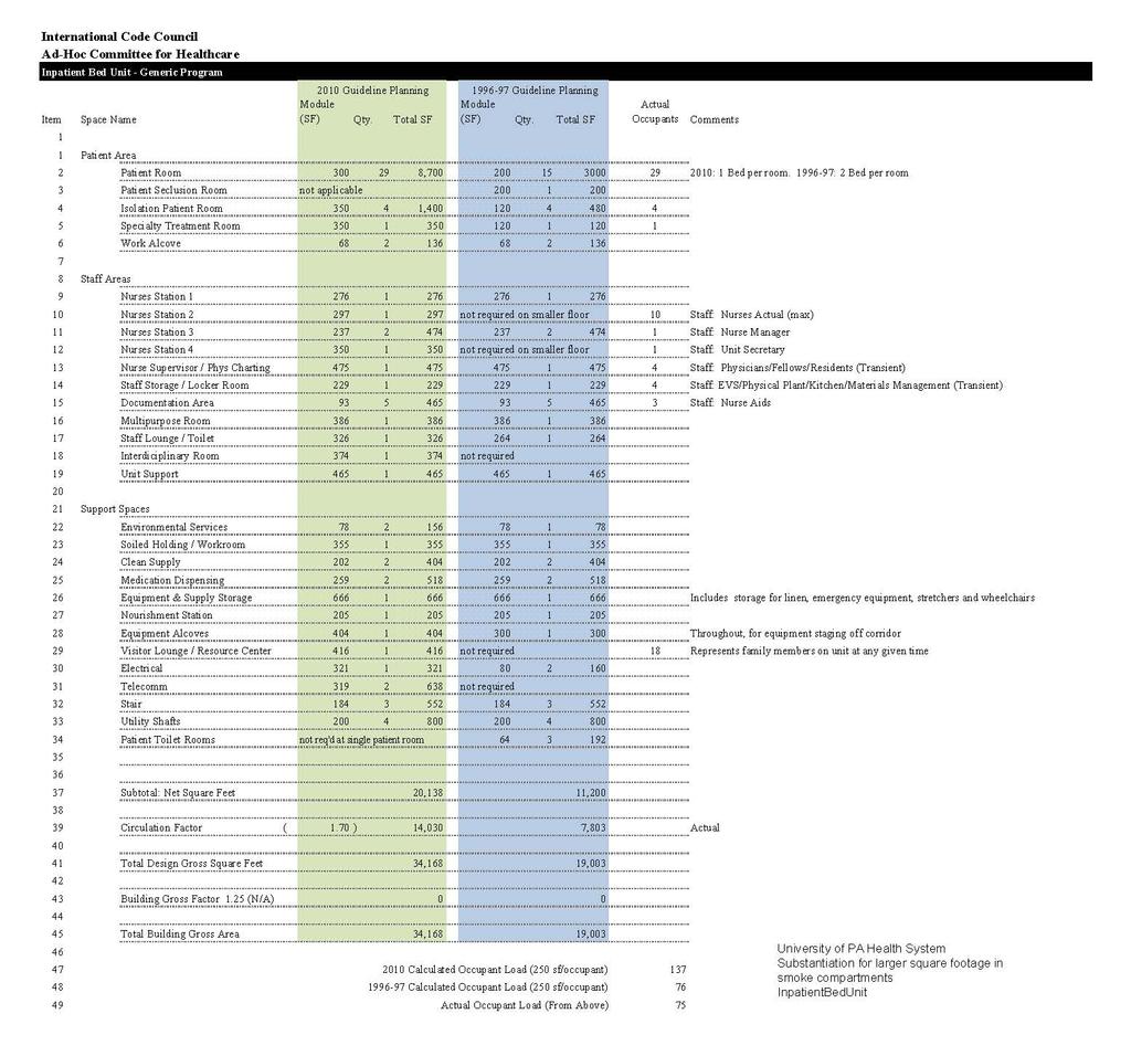
62 62 of 122
63 63 of 122
64 64 of 122


65 Cost Impact: Will increase the cost of construction This code change will increase the cost of construction as compared to the 2015 IBC, due to the need for some additional smoke barrier walls to create the smoke compartments smaller than the 40,000 sq. ft. smoke compartments. This code change will decrease the cost of construction as compared to the 2012 IBC, all previous editions of the IBC, all three of the legacy codes, and also as compared to the Life Safety Code (through 2015), due to the smoke compartments being larger than 22,500 sq. ft., and thus needing fewer smoke barrier walls than each of those codes could have required. G : LOVELL of 122
66 G Proponent: Amanda Hickman, InterCode Incorporated, representing Fire Safe North America 2015 International Building Code Revise as follows: Smoke barriers. Smoke barriers shall be provided to subdivide every story used by persons receiving care, treatment or sleeping and to divide other stories with an occupant load of 50 or more persons, into no fewer than two smoke compartments. Such stories shall be divided into smoke compartments with an area of not more than 22,500 square feet (2092 m 2 ) in Group I-2, Condition 1, and not more than 40,000 square feet (3716 m 2 ) in Group I-2, Condition 2, and the. The distance of travel from any point in a smoke compartment to a smoke barrier door shall be not greater than 200 feet ( mm). The smoke barrier shall be in accordance with Section 709. Reason: In the event of a fire, hospitals have a population with special concerns and vulnerabilities. To maintain an effective fire and smoke management system in health care environments, multiple compartments subdivided with smoke barrier walls must be incorporated and maintained in the life safety design for hospitals. A full evacuation is often neither practical nor in the best interest of hospital patients. Therefore, the International Building Code (IBC) and NFPA 101 Life Safety Code both require that the safety of patients in hospitals be provided through the use of a defend-in-place strategy using multiple fire safety features, including construction, compartmentation, fire detection and suppression, and a well-trained staff to assist in emergency relocation/evacuation of patients. Smoke barriers are used to separate smoke compartments. Walls and floors designed and constructed as smoke barriers separate adjacent smoke compartments in a building. Smoke barriers are required to be constructed with a minimal fire resistance rating of 1 hour. This will ensure that they are not quickly breached in the event of a fire, especially if sprinkler operation is delayed, shielded, or prevented altogether, such as due to a water supply impairment. As the name implies, smoke barriers are also intended to restrict the movement of smoke. Ensuring the ability of smoke barriers to survive exposure to a fire and to restrict smoke movement in a fire incident is critical to the defend-inplace concept used in health care. A key part of this strategy is to use smoke compartments formed by smoke barriers to create temporary, safe areas for patients. The International Building Code requires that areas used for patients must be divided into a minimum of two smoke compartments. Patients in smoke compartments not directly involved in a fire are protected at least temporarily, and can be moved horizontally on gurneys if necessary across smoke barriers into an adjacent smoke compartment. This will buy valuable time, depending on the circumstances, to avoid the need for total evacuation. Code changes in the 2015 Edition of the International Building Code resulted in the approval of two new code changes that changed smoke compartments in hospitals. Smoke compartments in I-2 occupancies are now less protected. Section (new exception #2 in the 2015 IBC) permits smoke barriers in smoke compartments to eliminate smoke dampers in smoke barriers in sprinklered I-2 buildings, if the HVAC system is fully ducted; and Section (2015 IBC) permits the area of smoke compartments in I-2, condition 2, to be nearly doubled in size, expanded in area from 22,500 sq. ft. to 40,000 sq. ft. The Section change represents two major changes to current requirements without substantial justification and without consideration of implementation of both changes to the protection of smoke compartments. Fire Safe North America (FSNA) was strongly opposed to both of the changes in the protection of smoke compartments and testified in opposition. (The Air Movement and Control Association Intl (AMCA) has submitted a code change this cycle that further clarifies when a smoke damper can be eliminated from the duct system.) Regarding the increased size of the smoke compartment, there was no correlation to the measurement of travel distances in a 40,000 sq. ft. compartment size. While travel distances are measured along a path of travel, the compartment sizes are measured in straight line distances. This major adjustment in smoke compartment size would potentially expose a greater number of patients to a fire incident, and establish the need for staff to relocate this higher number of patients to an adjacent area of safety, imposing an unacceptable level of safety for those patients. Current text has no limitations on the number of patients or the number of associated staff who may be located in any one smoke compartment. The change was based on the assumption that the size of functional patient areas has increased with no corresponding increase in patient population, but the code does not require such a limitation. The proposal that significantly increased the allowable area of a smoke compartment in hospitals from 22,500 sq. ft. to 40,000 sq. ft. did not adequately address numerous issues in their substantiation, and was not resolved satisfactorily. The following contains excerpts from testimony from those who were opposed to these changes, including the National Association of State Fire Marshals, Fire Safe North America, International Association of Fire Fighters, the International Firestop Council, the Air Movement and Control Association International, and others: 1. The substantiation provided for increasing smoke compartment size in hospitals from 22,500 sq. ft. to 40,000 sq. ft. was only based on a study showing that the size of functional patient areas is increasing in most hospitals (for example, to private patient rooms from semiprivate rooms) from the "Facilities Management Guidelines", and not on any technical substantiation addressing specific concerns of patient safety. 2. The new code section does not address the concerns related to increasing the travel time for egressing patients out of one smoke compartment into another one, and the fire and smoke safety impact on those patients and staff. 66 of 122
67 3. The new code section has no limitations on the maximum number of patients that may be located in any one 40,000 sq. ft. smoke compartment. Without limitations on patient or occupancy limits, a larger smoke compartment size than what was previously permitted, could expose a higher number of patients, visitors, and hospital staff to a fire incident. 4. The new code section could be interpreted to allow existing hospitals to increase smoke compartment sizes in order to reduce maintenance costs by decommissioning some of their smoke barriers without actually reducing the number of patients within their smoke compartments. An important point of interest is that an identical proposal to increase the size of a smoke compartment to 40,000 sq. ft. was proposed to the 2015 Life Safety Code, published and distributed worldwide by the National Fire Protection Association. Although approved narrowly by the Technical Committee, it was disapproved by the NFPA membership during the NFPA Association Members Meeting in Las Vegas in June, As a result, the change to 40,000 sq. ft. that is in the 2015 IBC and is not the 2015 Life Safety Code. There remains a conflict between the two regulatory documents, which causes problems for hospitals that need to comply with CMS regulations, as they require conformance with NFPA 101, including the 22,500 sq. ft. limitation on smoke compartment size. This proposal seeks to restore the size of the smoke compartments in hospitals to 22,500 sq. ft. which will make the Life Safety Code and the IBC consistent with one another. Cost Impact: Will increase the cost of construction This code change will increase the cost of construction as compared to the 2015 IBC, due to cost of constructing additional smoke barrier walls to make smoke compartments smaller than the currently required 40,000 sq. ft. smoke compartments. G : HICKMAN of 122
68 G Proponent: John Williams, CBO, Chair, representing Adhoc Health Care Committee 2015 International Building Code Revise as follows: Independent egress. A means of egress shall be provided from each smoke compartment created by smoke barriers without having to return through the smoke compartment from which means of egress originated. Smoke compartments that do not contain an exit shall be provided with direct access to not less than two adjacent smoke compartments. Reason: The ICC Ad Hoc Committee on Healthcare (AHC) has just completed its 4th year. The AHC was established by the ICC Board to evaluate and assess contemporary code issues relating to hospitals and ambulatory healthcare facilities. This is a joint effort between ICC and the American Society for Healthcare Engineering (ASHE), a subsidiary of the American Hospital Association, to eliminate duplication and conflicts in healthcare regulation. Information on the AHC, including: meeting agendas; minutes; reports; resource documents; presentations; and all other materials developed in conjunction with the AHC effort can be downloaded from the AHC website at: This code change is intended to more appropriately handle arrangement of the means of egress in a defend in place environment (i.e. hospitals and nursing homes.) The intent is to ensure that the arrangement of smoke compartments and exits prevents a situation where you have a "dead end smoke compartment." This requirement already exists within the federal Medicare requirements. This proposes rule (and the existing section) does not require a stair in every smoke compartment. In Example 1, an occupant in smoke compartment 2 (SC2) would be forced to travel into smoke compartment 1 to access one of the two required exits for the floor. This is compliant with the current requirement that the occupant does not "return through the smoke compartment of egress origin." The smoke compartment where the mean of egress originates is smoke compartment 2. The dashed path does not leave smoke compartment 2, then RETURN back into smoke compartment 2. While this example meets current code, it creates an unacceptable hazard by creating a "dead end smoke compartment." 68 of 122
69 Cost Impact: Will not increase the cost of construction This change will typically not increase the cost of construction, in that it does not affect how many exits are provided. It does limit the location on the floor plate, which could have cost implications. In worse case an additional smoke compartment would be required, which would definitely increase construction cost. Practically, since this is a federal requirement already there will be no perceived increase to facilities. 69 of 122
70 70 of 122 G : WILLIAMS4238
71 G (New), Proponent: John Williams, CBO, Chair, representing Adhoc Health Care Committee 2015 International Building Code Add new text as follows: Automatic closing doors Automatic closing doors with hold-open devices shall comply with Sections and Revise as follows: Group I-2 and ambulatory care facilities. In Group I-2 and ambulatory care facilities, where doors protecting openings in smoke barriers are installed across a corridor and have hold-open devices, the doors shall be automaticclosing by smoke detection in accordance with Section and. Such doors shall have a vision panel with fireprotection-rated glazing materials in fire-protection-rated frames, the area of which shall not exceed that tested. Reason: This proposal has two main functions: The first is to provide a pointer in the I-2 specific section to the requirements for automatic closing doors in healthcare facilities. The hold open feature is one that is used quite frequently, yet the specific requirements are often missed. The pointer in Chapter 4 will remind designers to comply with BOTH sections. The second change clarifies that not all cross corridor doors need to be provided with automatic closers. The context of this section is doors in smoke barriers, so we have added language to focus the requirement. The ICC Ad Hoc Committee on Healthcare (AHC) has just completed its 4th year. The AHC was established by the ICC Board to evaluate and assess contemporary code issues relating to hospitals and ambulatory healthcare facilities. This is a joint effort between ICC and the American Society for Healthcare Engineering (ASHE), a subsidiary of the American Hospital Association, to eliminate duplication and conflicts in healthcare regulation. Information on the AHC, including: meeting agendas; minutes; reports; resource documents; presentations; and all other materials developed in conjunction with the AHC effort can be downloaded from the AHC website at: Cost Impact: Will not increase the cost of construction This proposal is a clarification of requirements; therefore, there is no increase in cost. G : (New)-WILLIAMS of 122
72 G , 422.2, [F] (IFC ) Proponent: John Williams, CBO, Chair, representing Adhoc Health Care Committee 2015 International Building Code Revise as follows: SECTION 202 DEFINITIONS AMBULATORY CARE FACILITY. Buildings or portions thereof used to provide medical, surgical, psychiatric, nursing or similar care on a less than 24-hour basis to persons who are rendered incapable of self-preservation by the services provided or staff has accepted responsibility for care recipients already incapable Separation. Ambulatory care facilities where the potential for four or more care recipients are to be incapable of self-preservation at any time, whether rendered incapable by staff or staff accepted responsibility for a care recipient already incapable, shall be separated from adjacent spaces, corridors or tenants with a fire partition installed in accordance with Section 708. [F] Ambulatory care facilities. An automatic sprinkler system shall be installed throughout the entire floor containing an ambulatory care facility where either of the following conditions exist at any time: 1. Four or more care recipients are incapable of self-preservation, whether rendered incapable by staff or staff has accepted responsibility for care recipients already incapable. 2. One or more care recipients that are incapable of self-preservation are located at other than the level of exit discharge serving such a facility. In buildings where ambulatory care is provided on levels other than the level of exit discharge, an automatic sprinkler system shall be installed throughout the entire floor where such care is provided as well as all floors below, and all floors between the level of ambulatory care and the nearest level of exit discharge, including the level of exit discharge. Reason: This proposal modifies the definition of the term ambulatory care facility. The current definition envisions typical scenarios for when a care facility might house a person who is incapable of self preservation. The definition does not capture people who are unexpectedly incapable of preservation, such as a person fainting in an office building. It does capture those facilitites who intend to render a patient incapable. The point was brought up in one of the previous cycles, what about those facilities that accept responsibility for patients who are incapable. For example, free standing emergency centers. A code change was approved that addressed this change when setting sprinkler requirements. The code change moves that accepted concept into the definition from the two locations where it is currently found. The ICC Ad Hoc Committee on Healthcare (AHC) has just completed its 4th year. The AHC was established by the ICC Board to evaluate and assess contemporary code issues relating to hospitals and ambulatory healthcare facilities. This is a joint effort between ICC and the American Society for Healthcare Engineering (ASHE), a subsidiary of the American Hospital Association, to eliminate duplication and conflicts in healthcare regulation. Information on the AHC, including: meeting agendas; minutes; reports; resource documents; presentations; and all other materials developed in conjunction with the AHC effort can be downloaded from the AHC website at: Cost Impact: Will not increase the cost of construction This revision is a clarification. The proposal essentially moves text from the code to the defintion, therefore, this will not increase the construction. G : WILLIAMS of 122
73 G (New), (IBC [F] ) (New) Proponent: John Williams, CBO, Chair, representing Adhoc Health Care Committee 2015 International Building Code Add new text as follows: Electrical systems In ambulatory care facilities, the essential electrical system for electrical components, equipment and systems shall be designed and constructed in accordance with the provisions of Chapter 27 and NFPA International Fire Code (IBC [F] ) Ambulatory care facilities. Essential electrical systems for ambulatory care facilities shall be in accordance with Section of the International Building Code. Reason: The IBC currently has no direction on whether essential electrical systems (such as emergency generator) are required at ambulatory care facilities. This proposal adds the direction to go to NFPA 99, the Healthcare Facilities Code for that assessment. NFPA 99 provides a risk based approach to determine the need for an essential electrical system, what class system is required and general design requirements for each type of system. The ICC Ad Hoc Committee on Healthcare (AHC) has just completed its 4th year. The AHC was established by the ICC Board to evaluate and assess contemporary code issues relating to hospitals and ambulatory healthcare facilities. This is a joint effort between ICC and the American Society for Healthcare Engineering (ASHE), a subsidiary of the American Hospital Association, to eliminate duplication and conflicts in healthcare regulation. Information on the AHC, including: meeting agendas; minutes; reports; resource documents; presentations; and all other materials developed in conjunction with the AHC effort can be downloaded from the AHC website at: Cost Impact: Will increase the cost of construction The code change proposal will increase the cost of construction. Adding an essential electrical system will add the cost of a generator, as well as maintenance and testing over what is required currently in the IBC/IFC. However, any medicare certified ambulatory care facilities are required by federal CMS regulations to have this system, therefore, the cost of construction will not increase. Note that not all ambulatory care facilities are medicare certified. G : (New)-WILLIAMS of 122
74 G (New), (New) Proponent: Lee Kranz, City of Bellevue, WA, representing Washington Association of Building Officials Technical Code Development Committee 2015 International Building Code Add new text as follows: SECTION 427 MEDICAL GAS SYSTEMS Medical gas systems. Medical gas systems shall comply with Section 5306 of the International Fire Code. Reason: Provisions for medical gas installations are currently found in Section 5306 of the IFC but many of the requirements for these installations require a building permit and should also be regulated from the IBC. There are no substantive changes proposed to the language found in the IFC. Examples of similar references to other codes and standards are found in Sections 425 & 916. Cost Impact: Will not increase the cost of construction Inserting a reference to the medical gas regulations currently found in the IFC will not change the cost of installation. G : 427 (New)-KRANZ of 122
75 G Proponent: John Williams, CBO, Chair, representing Adhoc Health Care Committee 2015 International Building Code Revise as follows: Occupancy classification. Nonseparated occupancies shall be individually classified in accordance with Section The requirements of this code shall apply to each portion of the building based on the occupancy classification of that space. In addition, the most restrictive provisions of Chapter 9 that apply to the nonseparated occupancies shall apply to the total nonseparated occupancy area. Where nonseparated occupancies occur in a highrise building, the most restrictive requirements of Section 403 that apply to the nonseparated occupancies shall apply throughout the high-rise building. Where one of the non-separated occupancies is Group I-2, Condition 2, the most restrictive requirements of Sections 407, 509, 712, and Chapter 10 shall apply. Reason: This proposal modifies the requirements for non-separated mixed uses. In a hospital buildings, it is important to maintain some fire protection features throughout the building. Many of these restrictions directly support the defend-in-place concept that hospitals rely on. Specifically included are incidental use areas, protected vertical openings, and hospital-specific egress provisions. As written, the current code would allow an unprotected vertical opening to be located in the non-separated business portion of a hospital building. Arguably you could use the definition of a smoke compartment to challenge this idea, but that argument is very subtle and highlights an inherent conflict ion the code. Section 407 is specific to I-2 occupancies, not to building that contain I-2 occupancies. Yet section 407 contains provisions for corridor construction, smoke compartmentation and hospital specific egress provisions that should be maintained to support the defend in place concept. By clearly stating in this section that there are some concepts in a hospital building that need to be treated differently, we can provide clear direction to designers and enforcers. This code change is needed to be consistent with the requirements of Medicaid and Medicare (CMS.) The ICC Ad Hoc Committee on Healthcare (AHC) has just completed its 4th year. The AHC was established by the ICC Board to evaluate and assess contemporary code issues relating to hospitals and ambulatory healthcare facilities. This is a joint effort between ICC and the American Society for Healthcare Engineering (ASHE), a subsidiary of the American Hospital Association, to eliminate duplication and conflicts in healthcare regulation. Information on the AHC, including: meeting agendas; minutes; reports; resource documents; presentations; and all other materials developed in conjunction with the AHC effort can be downloaded from the AHC website at: Cost Impact: Will increase the cost of construction While this is an increase in construction based on only IBC requirements, however, this is a requirement from federal CMS in hospitals; therefore, this is not an increase in actual construction cost. G : WILLIAMS of 122
76 FG (New) Proponent: John Williams, CBO, Chair, representing Adhoc Health Care Committee 2015 International Fuel Gas Code Add new text as follows: Fireplaces and decorative appliances in Group I-2 Condition 2 occupancies. Gas fireplace appliances and decorative gas appliances shall be prohibited in Group I-2, condition 2 occupancies except in public lobby and waiting areas that are not within smoke compartments containing patient sleeping areas. Such fireplace appliances and decorative appliances shall be installed in accordance with all of the following: 1. The appliances shall be vented to the outdoors. 2. The appliances be of the direct-vent type. 3. The appliances shall automatically shut off upon activation of the fire alarm system serving the occupancy. 4. The appliance controls shall be located where they can be accessed only by facility staff. 5. A carbon monoxide detector with a local alarm shall be provided and installed in accordance with Section 915 of the International Fire Code. Reason: The AHC committee is recommending limitations for the use of fuel gas-fired fireplaces and decorative equipment and the restriction of solid-fuel burning fireplaces and appliances in the Group I-2, Condition 2 occupancy. Please note: these are not new requirements for the Group I-2 Occupancy facilities but are needed in the I-Codes for coordination of the long-standing provision of the construction and operational requirements for healthcare facilities. It is standard practice and operational procedure to control the ignition sources in healthcare occupancies that can contain combustible, flammable (and sometimes even explosive) material. Fire risks need to be limited to the maximum extent feasible and specific requirements for these facilities are not currently or are not completely addressed in the I-Codes. The language proposed in the IFGC prescribes limitations and conditions to provide the necessary safety and limitations of hazards from within the healthcare environments to the fire and ignition sources inherent to all gas-fired fireplaces and appliances. Combustion air has been restricted from being drawn from healthcare environments extending beyond the last decade and is not a new requirement. The physical separation of the combustion chambers of gas-fired fireplaces and equipment is required to separate and provide a barrier between the ignition sources and the environmental air within healthcare occupancies. All combustion air is required to be taken directly from the exterior of the building in accordance with an existing exception that is provided for in IFGC Section The placement of solid fuel burning fireplaces and appliances, both decorative and heating, creates conditions where open flames that are not otherwise able to be controlled or extinguished like the similar gas-fed and fired appliances. This is why the Adhoc Healthcare Committee is proposing their restriction instead of a limitation with operational and special control equipment. The code sections that address the installation limitations of fuel gas-fired fireplaces and appliances will also provide alternative means for compliance for existing facilities. Given the hazards present with these appliances in the Group I-2, Condition 2 Occupancies, the proposed IFC requirements will be 'retro-active' requirements for healthcare occupancies (Group I-2); The proposals to the IFC that are being put forth by the Adhoc Healthcare Committee have been drafted to clarify, restrict and limit the ignition source hazards in healthcare occupancies and also will reference similar requirements being proposed in the IBC, IMC AND IFGC. For instance, solid fuel heating appliances are limited by other requirements of the IMC which is why heating appliances are not needed to be referenced in this section of the IFGC. There was a concern mentioned during testimony at the code hearings for the 2012 I-codes that the AHC code change proposals placing restrictions on solid fuel burning fireplaces and appliances and fuel gas-fired fireplaces and appliances might be misinterpreted to prohibit mechanical heating equipment elsewhere regulated in the IMC. The ICC Ad Hoc Committee on Healthcare (AHC) has just completed its 4th year. The AHC was established by the ICC Board to evaluate and assess contemporary code issues relating to hospitals and ambulatory healthcare facilities. This is a joint effort between ICC and the American Society for Healthcare Engineering (ASHE), a subsidiary of the American Hospital Association, to eliminate duplication and conflicts in healthcare regulation. Information on the AHC, including: meeting agendas; minutes; reports; resource documents; presentations; and all other materials developed in conjunction with the AHC effort can be downloaded from the AHC website. Cost Impact: Will not increase the cost of construction Wood burning fireplaces are not permitted by the federal CMS regulations, therefore, there is no change in cost of construction. 76 of 122 FG : (New)- WILLIAMS4239
77 M (New), (New) Proponent: John Williams, CBO, Chair, representing Adhoc Health Care Committee 2015 International Mechanical Code Add new text as follows: Fireplaces in Group I-2 Condition 2 occupancies. Fuel burning appliances and fireplaces in Group I-2 condition 2 occupancies shall be in accordance with Section Solid fuel-burning fireplaces and appliances in Group I-2 Condition 2. In Group I-2 Condition 2 occupancies, solid fuel-burning fireplaces and appliances are prohibited. Reason: The AHC committee is recommending limitations for the use of gas-fired fireplaces and decorative equipment and the restriction of solid-fuel burning fireplaces and appliances in the Group I-2, Condition 2 occupancy. Please note: these are not new requirements for the I-2 Occupancy facilities but are needed in the I-Codes for coordination of the long-standing provision of the construction and operational requirements for healthcare facilities. It is standard practice and operational procedure to control the ignition sources in healthcare occupancies that can contain combustible, flammable (and sometimes even explosive) material. Fire risks need to be limited to the maximum extent feasible and specific requirements for these facilities are not currently or are not completely addressed in the I-Codes. The language proposed in the IFGC prescribes limitations and conditions to provide the necessary safety and limitations of hazards from within the healthcare environments to the fire and ignition sources inherent to all gas-fired fireplaces and appliances. Combustion air has been restricted from being drawn from healthcare environments extending beyond the last decade and is not a new requirement. The physical separation of the combustion chambers of gas-fired fireplaces and equipment is required to separate and provide a barrier between the ignition sources and the environmental air within healthcare occupancies. All combustion air is required to be taken directly from the exterior of the building in accordance with an existing exception that is provided for in IFGC Section The placement of solid fuel burning fireplaces and appliances, both decorative and heating, creates conditions where open flames that are not otherwise able to be controlled or extinguished like the similar gas-fed and fired appliances. This is why the Adhoc Healthcare Committee is proposing their restriction instead of a limitation with operational and special control equipment. The code sections that address the installation limitations of fuel gas-fired fireplaces and appliances will also provide alternative means for compliance for existing facilities. Given the hazards present with these appliances in the Group I-2, Condition 2 Occupancies, the proposed IFC requirements will be 'retro-active' requirements for healthcare occupancies (I-2); The proposals to the IFC that are being put forth by the Adhoc Healthcare Committee have been drafted to clarify, restrict and limit the ignition source hazards in healthcare occupancies and also will reference similar requirements being proposed in the IBC, IMC AND IFGC. For instance, solid fuel heating appliances are limited by other requirements of the IMC which is why heating appliances are not needed to be referenced in this section of the IFGC. There was a concern mentioned during testimony at the code hearings for the 2012 I-codes that the AHC code change proposals placing restrictions on solid fuel burning fireplaces and appliances and fuel gas-fired fireplaces and appliances might be misinterpreted to prohibit mechanical heating equipment elsewhere regulated in the IMC. The ICC Ad Hoc Committee on Healthcare (AHC) has just completed its 4th year. The AHC was established by the ICC Board to evaluate and assess contemporary code issues relating to hospitals and ambulatory healthcare facilities. This is a joint effort between ICC and the American Society for Healthcare Engineering (ASHE), a subsidiary of the American Hospital Association, to eliminate duplication and conflicts in healthcare regulation. Information on the AHC, including: meeting agendas; minutes; reports; resource documents; presentations; and all other materials developed in conjunction with the AHC effort can be downloaded from the AHC website at: Cost Impact: Will not increase the cost of construction Wood burning fireplaces are not permitted by the federal CMS regulations, therefore, there is no change in cost of construction. M : (New)-WILLIAMS of 122
78 M , Proponent: Mike Moore, Newport Ventures, representing Broan-NuTone, representing Newport 2015 International Mechanical Code Revise as follows: Ventilation required. Every occupied space shall be ventilated by natural means in accordance with Section 402 or by mechanical means in accordance with Section 403. WhereMechanical ventilation shall be required for the following: 1. Dwelling units where the air infiltration rate in a dwelling unit is less than 5 air changes per hour when tested with a blower door at a pressure of 0.2-inch water column (50 Pa) in accordance with Section R of the International Energy Conservation Code., the 2. Kitchens in dwelling unit shall be ventilated by mechanical means in accordance with Section 403units. 3. Ambulatory care facilities and Group I-2 occupancies. Such ventilation shall be ventilated by mechanical means in accordance with Section Exhaust discharge. The air removed by every mechanical exhaust system shall be discharged outdoors at a point where it will not cause a public nuisance and not less than the distances specified in Section The air shall be discharged to a location from which it cannot again be readily drawn in by a ventilating system. Air shall not be exhausted into an attic, crawl space, or be directed onto walkways. Exceptions: 1. Whole-house ventilation-type attic fans shall be permitted to discharge into the attic space of dwelling units having private attics. 2. Commercial cooking recirculating systems. 3. Where installed in accordance with the manufacturer's instructions and where mechanical or natural ventilation is otherwise provided in accordance with Chapter 4, listed and labeled domestic ductless range hoods shall not be required to discharge to the outdoors. Reason: Pollutants from cooking have been identified as some of the worst in the home, in terms of health impacts. Pollution during cooking events includes NO 2, CO, HCHO (formaldehyde), acrolein (produced when cooking meats and oils; used as a nerve agent in WWI), polycyclic aromatic hydrocarbons, and particulate matter (which can become lodged in the lungs or pass through the lungs to the circulatory system. 1,2,3,4,5,6,17,18,19,20,21 Overall, indoor air pollution from residential dwelling units (excluding the impacts of radon and second hand smoke) is estimated to account for 14% of all years of life lost and years of disability associated with "noncommunicable and nonpsychiatric diseases." 7 Based on another study, this is roughly equal to the negative health impacts of alcohol use, diabetes, and HIV/AIDS combined. 8 The lion's share of the health impacts of poor indoor air quality in dwelling units has been linked to particulate matter, and indoor particulate matter is emitted when cooking on both electric and gas stoves. 3,7,9 Overall, the primary source of particulate matter in non-smoking dwelling units is unvented cooking. 1 Natural ventilation alone is an insufficient means to provide required ventilation because it relies on pressure differentials that may or may not exist, and when they exist, the pressure differential could be equally as likely to spread the pollutant throughout the dwelling unit and neighboring units as it would be to exhaust the pollutant directly to the outdoors. Further, studies have shown that occupants often do not operate windows for ventilation. 10,11 Concerns with window operation include security and discomfort (including severe draft in winter). To improve the health and life safety of dwelling unit occupants, this proposal would require that mechanical ventilation be provided for all kitchens in dwelling units. Some compelling facts and quotes on kitchen pollutants and ventilation follow. Simulations show that where a natural gas cooktop is used without a vented range hood, "62%, 9%, and 53% of occupants are routinely exposed to NO 2, CO, and HCHO (formaldehyde) levels that exceed acute health-based standards and guidelines." 12 "Emissions of nitrogen dioxide in homes with gas stoves exceed the EPA's definition of clean air in an estimated 55 percent to 70 percent of those homes, according to one model; a quarter of them have air quality worse than the worst recorded smog (nitrogen dioxide) event in London. Cooking represents one of the single largest contributors, generating particulate matter (formally known as PM2.5) at concentrations four times greater than major haze events in Beijing." 13 Increased exposure to NO 2 in dwelling units has been associated with an increased number of asthma attacks. 14,15,16 "People don't need to radically change their lifestyles. We need to change the building codes so that everyone gets a venting range hood."- Dr. Jennifer Logue, Research Scientist with Lawrence Berkeley National Laboratory of 122
79 Bibliography: 1. Wallace, L. A., Emmerich, S. J., & Howard-Reed, C. (2004). Source strengths of ultrafine and fine particles due to cooking with a gas stove. Environmental Science & Technology, 38(8), Singer, B. C., Apte, M. G., Black, D. R., Hotchi, T., Lucas, D., Lunden, M. M.,... Sullivan, D. P. (2010). Natural Gas Variability in California: Environmental Impacts and Device Performance: Experimental Evaluation of Pollutant Emissions from Residential Appliances. Sacramento CA: California Energy Commission. 3. Dennekamp, M., Howarth, S., Dick, C. A. J., Cherrie, J. W., Donaldson, K., & Seaton, A. (2001). Ultrafine particles and nitrogen oxides generated by gas and electric cooking. Occupational and Environmental Medicine, 58(8), Moschandreas, D. J., & Relwani, S. M. (1989). Field-Measurements of NO2 Gas Range-Top Burner Emission Rates. Environment International, 15(1-6), Moschandreas, D., Relwani, S., Johnson, D., & Billick, I. (1986). Emission Rates from Unvented Gas Appliances. Environment International, 12(1-4), EPA. Fine Particle Designations. Available at Sourced on December 10, Logue et al. (2012). A method to estimate the chronic health impact of air pollutants in U.S. residences. Environmental Health Perspectives: 120(2): McKenna, M.T., C.M. Michaud, C.J.L. Murray, and J.S. Marks. (2005). Assessing the burden of disease in the United States using disability-adjusted life years. Am J Prev Med.: 28(5): Nicole, W. (2014). Cooking Up Indoor Air Pollution: Emissions from Natural Gas Stoves. Environ Health Perspect: 122-A Offerman, F.J. (2009). Ventilation and indoor air quality in new homes. PIER Collaborative Report. California Energy Commission & California Environmental Protection Agency Air Resources Board. 11. Klug, V. L., Lobscheid, A. B., & Singer, B. C. (2011). Cooking Appliance Use in California Homes Data Collected from a Web-Based Survey LBNL-5028E. Berkeley, CA: Lawrence Berkeley National Laboratory. 12. Logue et al. (2014). Pollutant exposures from natural gas cooking burners: a simulation based assessment for Southern California." Lawrence Berkeley National Laboratory. LBNL-6712E. 13. Smith, P.A. (2013). The Kitchen as a Pollution Hazard. New York Times. Accessed December 10, Belanger, K., Gent, J. F., Triche, E. W., Bracken, M. B., & Leaderer, B. P. (2006). Association of indoor nitrogen dioxide exposure with respiratory symptoms in children with asthma. American Journal of Respiratory and Critical Care Medicine, 173(3), doi: /rccm OC. 15. Hansel, N. N., Breysse, P. N., McCormack, M. C., Matsui, E. C., Curtin-Brosnan, J., Williams, D. L.,... Diette, G. B. (2008). A longitudinal study of indoor nitrogen dioxide levels and respiratory symptoms in inner-city children with asthma. Environmental Health Perspectives, 116(10), doi: /ehp Garrett, M. H., Hooper, M. A., Hooper, B. M., & Abramson, M. J. (1998). Respiratory symptoms in children and indoor exposure to nitrogen dioxide and gas stoves. American Journal of Respiratory and Critical Care Medicine, 158(3), Abdullahi, K. L., Delgado-Saborit, J. M., & Harrison, R. M. (2013). Emissions and indoor concentrations of particulate matter and its specific chemical components from cooking: A review. Atmospheric Environment, 71, doi: Doi /J.Atmosenv Buonanno, G., Morawska, L., & Stabile, L. (2009). Particle emission factors during cooking activities. Atmospheric Environment, 43(20), doi: Doi /J.Atmosenv Fortmann, R., Kariher, P., & Clayton, R. (2001). Indoor air quality: residential cooking exposures. Sacramento, CA: Prepared for California Air Resources Board. 20. Seaman, V. Y., Bennett, D. H., & Cahill, T. M. (2009). Indoor acrolein emission and decay rates resulting from domestic cooking events. Atmospheric Environment, 43(39), doi: /j.atmosenv Zhang, Q. F., Gangupomu, R. H., Ramirez, D., & Zhu, Y. F. (2010). Measurement of Ultrafine Particles and Other Air Pollutants Emitted by Cooking Activities. International Journal of Environmental Research and Public Health, 7(4), doi: /ijerph Cost Impact: Will increase the cost of construction For those units that do not already install kitchen exhaust, the cost of construction will increase, depending on equipment selection. Exhaust hoods start around $30 retail (e.g., Broan economy hood #403001, 2-speed, moving 160 cfm, priced on zoro.com at $33.36 with free shipping on December 19, 2014). Most dwelling units have some sort of recirculating exhaust hood at a minimum, so the actual incremental cost could probably be disregarded for the equipment itself. For units that are recirculating only, installed cost to the GC for ducting is estimated at ~$13/linear foot for 3.25x10" duct (RS Means 2013 Residential Cost Data, adjusted for inflation). M : MOORE of 122
80 M Proponent: Guy McMann, Jefferson County Colorado, representing Colorado Association of Plumbing and Mechanical Officials (CAPMO) 2015 International Mechanical Code Revise as follows: Domestic systems. Where domestic range hoods and domestic appliances equipped with downdraft exhaust are provided, such hoods and appliances shall discharge to the outdoors through sheet metal ducts constructed of galvanized steel, stainless steel, aluminum or copper. Such ducts shall have smooth inner walls, shall be air tight, shall be equipped with a backdraft damper, and shall be independent of all other exhaust systems. Exceptions: 1. In other than Group I-1 and I-2, where installed in accordance with the manufacturer's instructions and where mechanical or natural ventilation is otherwise provided in accordance with Chapter 4, listed and labeled ductless range hoods shall not be required to discharge to the outdoors. Installations in Group I-1 and Group I-2 occupancies shall be in accordance with Section of the International Building Code and Section of the International Fire Code. 2. Ducts for domestic kitchen cooking appliances equipped with downdraft exhaust systems shall be permitted to be constructed of Schedule 40 PVC pipe and fittings provided that the installation complies with all of the following: 2.1. The duct shall be installed under a concrete slab poured on grade The underfloor trench in which the duct is installed shall be completely backfilled with sand or gravel The PVC duct shall extend not more than 1 inch (25 mm) above the indoor concrete floor surface The PVC duct shall extend not more than 1 inch (25 mm) above grade outside of the building The PVC ducts shall be solvent cemented. Reason: These pointers are going to aid the user in finding the pertinant information regarding fire suppresion for these range hoods. It can be very time consuming trying to locate the correct language for a code compliant installation. The user would never know that fire suppresion is even required without these pointers. Cost Impact: Will not increase the cost of construction There is no cost impact as this proposal is strictly editorial in nature. M : MCMANN of 122
81 P Table (IBC Table ) Proponent: Stephen DiGiovanni, Clark County Building Department, representing Southern Nevada Chapter of ICC 2015 International Plumbing Code Revise as follows: TABLE MINIMUM NUMBER OF REQUIRED PLUMBING FIXTURES a (See Sections and 403.2) WATER CLOSETS (URINALS: SEE SECTION 419.2) LAVATORIES BATHTUBS/ DRINKING FOUNTAIN (SEE SECTION NO. CLASSIFICATION OCCUPANCY DESCRIPTION MALE FEMALE MALE FEMALE SHOWERS 410) OTHER Theaters and A-1 d other buildings for the performing arts and motion 1 service sink e pictures Nightclubs, A-2 d bars, taverns, dance halls and buildings for similar purposes 1 service sink e Restaurants, banquet halls and food courts 1 service sink e 1 Assembly Auditoriums without permanent seating, art galleries, exhibition halls, museums, lecture halls, 1 service sink e libraries, A-3 d arcades and gymnasiums Passenger terminals and transportation facilities 1 service sink e Places of worship and other religious services 1 service sink e 81 of 122
82 WATER CLOSETS (URINALS: SEE SECTION 419.2) LAVATORIES BATHTUBS/ DRINKING FOUNTAIN (SEE SECTION NO. CLASSIFICATION OCCUPANCY DESCRIPTION MALE FEMALE MALE FEMALE SHOWERS 410) OTHER Coliseums, arenas, A-4 skating rinks, pools and tennis courts for indoor sporting 1 service sink e events and 1 (cont.) Assembly activities Stadiums, amusement A-5 parks, bleachers and grandstands for outdoor sporting 1 service sink e events and activities 2 Business B Buildings for the transaction of business, professional services, other services involving merchandise, office buildings, banks, light industrial and similar uses 1 service sinke 3 Educational E Educational facilities 1 service sink e Structures in which occupants are 4 Factory and industrial F-1 and F-2 engaged in work fabricating, assembly or 1 service sink e processing of products or materials Residential 1 I-1 care service sink e 82 of 122
83 Hospitals, ambulatory nursing home care recipient 1 service sink per floor e I-2 Employees, other than residential careb Visitors, other 5 Institutional than residential care Prisonsb 1 service sink e Reformitories, I-3 detention centers, and correctional centersb 1 service sink e Employeesb I-4 Adult day care and child day care 1 service sink e WATER CLOSETS DRINKING (URINALS: SEE FOUNTAIN SECTION 419.2) LAVATORIES (SEE BATHTUBS/ SECTION NO. CLASSIFICATION OCCUPANCY DESCRIPTION MALE FEMALE MALE FEMALE SHOWERS 410) OTHER Retail stores, service 6 Mercantile M stations, shops, salesrooms, markets and shopping centers 1 service sink e R-1 Hotels, motels, boarding houses (transient) 1 service sink e R-2 Dormitories, fraternities, sororities and boarding houses (not transient) 83 of service sink e
84 7 Residential R-2 Apartment house 1 kitchen sink per dwelling unit; 1 automatic clothes washer connection per 20 dwelling units R-3 Congregate living facilities with 16 or fewer persons 1 service sink e R-3 One- and twofamily dwellings and lodging houses with five or fewer guestrooms 1 kitchen sink per dwelling unit; 1 automatic clothes washer connection per dwelling unit R-4 Congregate living facilities with 16 or fewer persons 1 service sink e 8 Storage S-1 S-2 Structures for the storage of goods, warehouses, store- house and freight depots. Low and Moderate Hazard. 1 service sink e (Portions of table not shown remain unchanged) a. The fixtures shown are based on one fixture being the minimum required for the number of persons indicated or any fraction of the number of persons indicated. The number of occupants shall be determined by the International Building Code. b. Toilet facilities for employees shall be separate from facilities for inmates or care recipients. c. A single-occupant toilet room with one water closet and one lavatory serving not more than two adjacent patient sleeping units shall be permitted provided that each patient sleeping unit has direct access to the toilet room and provision for privacy for the toilet room user is provided. d. The occupant load for seasonal outdoor seating and entertainment areas shall be included when determining the minimum number of facilities required. e. For business and mercantile occupancies with an occupant load of 15 or fewer,sservice sinks shall not be required. where the occupant load is 30 or fewer. 84 of 122
85 Reason: This proposal revises note e and applies note "e" to each of the service sink entries in the table, so that it addresses all occupancies required to have service sinks, not just B and M occupancies. Note "e" is revised to trigger the service sink at an occupant load of over 30, rather than the current trigger of 15 found in the note. Cost Impact: Will not increase the cost of construction This proposal provides a more lenient approach for fixture requirements, so the cost of construction is not increased. P : T403.1-DIGIOVANNI of 122
86 P Table (IBC Table ) Proponent: Janine Snyder, representing Plumbing, Mechanical, and Fuel Gas Code Action Committee 2015 International Plumbing Code Revise as follows: TABLE MINIMUM NUMBER OF REQUIRED PLUMBING FIXTURES a (See Sections and 403.2) WATER CLOSETS (URINALS: SEE SECTION 419.2) LAVATORIES BATHTUBS/ DRINKING FOUNTAIN (SEE SECTION NO. CLASSIFICATION OCCUPANCY DESCRIPTION MALE FEMALE MALE FEMALE SHOWERS 410) OTHER A-1 d Theaters and other buildings for the performing arts and motion pictures A-2 d Nightclubs, bars, taverns, dance halls and buildings for similar purposes Restaurants, banquet halls and food courts 1 Assembly A-3 d Auditoriums without permanent seating, art galleries, exhibition halls, museums, lecture halls, libraries, arcades and gymnasiums Passenger terminals and transportation facilities Places of worship and other religious services 86 of 122
87 WATER CLOSETS (URINALS: SEE SECTION 419.2) LAVATORIES BATHTUBS/ DRINKING FOUNTAIN (SEE SECTION NO. CLASSIFICATION OCCUPANCY DESCRIPTION MALE FEMALE MALE FEMALE SHOWERS 410) OTHER Coliseums, arenas, skating rinks, pools and A-4 tennis courts for indoor sporting events and 1 (cont.) Assembly activities Stadiums, amusement parks, bleachers and A-5 grandstands for outdoor sporting events and activities 2 Business B Buildings for the transaction of business, professional services, other services involving merchandise, office buildings, banks, light industrial and similar uses 3 Educational E Educational facilities Structures in which occupants are engaged in 4 Factory and industrial F-1 and F-2 work fabricating, assembly or processing of products or materials I-1 Residential care 87 of 122
88 Hospitals, ambulatory nursing home care recipient I-2 Employees, other than residential careb 5 Institutional Visitors, other than residential care Prisonsb I-3 Reformitories, detention centers, and correctional centersb Employeesb I-4 Adult day care and child day care WATER CLOSETS (URINALS: SEE SECTION 419.2) LAVATORIES BATHTUBS/ DRINKING FOUNTAIN (SEE SECTION NO. CLASSIFICATION OCCUPANCY DESCRIPTION MALE FEMALE MALE FEMALE SHOWERS 410) OTHER 6 Mercantile M Retail stores, service stations, shops, salesrooms, markets and shopping centers R-1 Hotels, motels, boarding houses (transient) R-2 Dormitories, fraternities, sororities and boarding houses (not transient) 88 of 122
89 7 Residential R-2 R-3 Apartment house Congregate living facilities with 16 or fewer persons R-3 One- and twofamily dwellings and lodging houses with five or fewer guestrooms R-4 Congregate living facilities with 16 or fewer persons 1 per 10 1 per 10 1 per 8 1 per service sink Structures for the storage of goods, warehouses, 8 Storage S-1 S-2 store- house and freight depots. Low and Moderate Hazard. (Portions of table not shown remain unchanged) a. The fixtures shown are based on one fixture being the minimum required for the number of persons indicated or any fraction of the number of persons indicated. The number of occupants shall be determined by the International Building Code. b. Toilet facilities for employees shall be separate from facilities for inmates or care recipients. c. A single-occupant toilet room with one water closet and one lavatory serving not more than two adjacent patient sleeping units shall be permitted provided that each patient sleeping unit has direct access to the toilet room and provision for privacy for the toilet room user is provided. d. The occupant load for seasonal outdoor seating and entertainment areas shall be included when determining the minimum number of facilities required. e. For business and mercantile occupanciesclassifications with an occupant load of 15 or fewer, service sinks shall not be required. Reason: Section was revised for the 2015 IPC to direct the reader to the use of a building rather than its IBC occupancy classification (Group) for determining the number of plumbing fixtures. The occupancy column is Table is now really confusing as Section says to use the Description column but this Occupancy column implies that the IBC classification is to be used. This proposal removes the occupancy column for clarity and coordination with what Section states. Table will still retain the classification column, although that column doesn't seem to add any clarification to the table as the IPC doesn't speak of "classifications" for various uses. However, as Table is reprinted in the IBC (as Table [P] ), the classification column might incorrectly lead IBC readers to assume that the IBC occupancy classification (Group) has something to do with selection of an appropriate row for plumbing fixture requirements. IBC Section [P] is identical to Section in the IPC but if the reader neglects reading the IBC section and jumps directly to the table, the existence of classification column could cause a misunderstanding. This proposal is submitted by the ICC Plumbing, Mechanical and Fuel Gas Code Action Committee (PMGCAC) The PMGCAC was established by the ICC Board of Directors to pursue opportunities to improve and enhance assigned International Codes or portions thereof. This includes both the technical aspects of the codes and the code content in terms of scope and application of referenced standards. The PMGCAC has held one open meeting and multiple conference calls which included members of the PMGCAC. Interested parties also participated in all conference calls to discuss and debate the proposed changes. This is PMGCAC Item 191. Cost Impact: Will not increase the cost of construction This proposal will not increase the cost of construction because no additional labor, materials, equipment, appliances or devices are mandated beyond what is currently required by the code. P : T403.1-SNYDER of 122
90 P , 609.1, Proponent: John Williams, CBO, Chair, representing Adhoc Health Care Committee 2015 International Plumbing Code Revise as follows: Scope. This section shall govern those aspects of health care plumbing systems that differ from plumbing systems in other structures. Health care plumbing systems shall conform to the requirements of this section in addition to the other requirements of this code. The provisions of this section shall apply to the special devices and equipment installed and maintained in the following occupancies: nursing homesgroup I-1, homes for the agedgroup I-2, orphanages, infirmaries, first aid stations, psychiatricgroup B ambulatory care facilities, clinics, professionalmedical offices of dentists and doctors, mortuaries, educational facilities, surgery, dentistry, research and testing laboratories, establishmentsand Group F facilities manufacturing pharmaceutical drugs and medicines and other structures with similar apparatus and equipment classified as plumbing Scope. This section shall govern those aspects of health care plumbing systems that differ from plumbing systems in other structures. Health care plumbing systems shall conform to the requirements of this section in addition to the other requirements of this code. The provisions of this section shall apply to the special devices and equipment installed and maintained in the following occupancies: nursing homesgroup I-1, homes for the agedgroup I-2, orphanages, infirmaries, first aid stations, psychiatricgroup B ambulatory care facilities, clinics, professionalmedical offices of dentists and doctors, mortuaries, educational facilities, surgery, dentistry, research and testing laboratories, establishmentsand Group F facilities manufacturing pharmaceutical drugs and medicines and other structures with similar apparatus and equipment classified as plumbing Scope. This section shall govern those aspects of health care plumbing systems that differ from plumbing systems in other structures. Health care plumbing systems shall conform to this section in addition to the other requirements of this code. The provisions of this section shall apply to the special devices and equipment installed and maintained in the following occupancies: nursing homes; homes for the aged; orphanages; infirmaries; first aid stations; psychiatricgroup I-1, Group I-2, Group B ambulatory care facilities; clinics; professional, medical offices of dentists and doctors; mortuaries; educational facilities; surgery, dentistry, research and testing laboratories; establishments, and Group F facilities manufacturing pharmaceutical drugs and medicines; and other structures with similar apparatus and equipment classified as plumbing. Reason: This proposal replaces a laundry list of healthcare related facilities with the corresponding occupancy groups. These occupancy groups are the ones most likely to have healthcare related activity that might have an impact on the supply and waste systems. The ICC Ad Hoc Committee on Healthcare (AHC) has just completed its 4th year. The AHC was established by the ICC Board to evaluate and assess contemporary code issues relating to hospitals and ambulatory healthcare facilities. This is a joint effort between ICC and the American Society for Healthcare Engineering (ASHE), a subsidiary of the American Hospital Association, to eliminate duplication and conflicts in healthcare regulation. Information on the AHC, including: meeting agendas; minutes; reports; resource documents; presentations; and all other materials developed in conjunction with the AHC effort can be downloaded from the AHC website at: Cost Impact: Will not increase the cost of construction This proposal is clarification only, therefore, the cost of construction will not change. P : WILLIAMS of 122
91 P Proponent: John Williams, CBO, Chair, representing Adhoc Health Care Committee 2015 International Plumbing Code Delete without substitution: Special elevations. Control valves, vacuum outlets and devices protruding from a wall of an operating, emergency, recovery, examining or delivery room, or in a corridor or other location where patients are transported on a wheeled stretcher, shall be located at an elevation that prevents bumping the patient or stretcher against the device. Reason: Clinical needs must determine the location of control valves, vacuum outlets and other plumbing control devices. The chance that a patient or stretcher could accidentally bump them is too broad for consistent interpretation. Given the need for ready access to some of these devices this could cause conflicts with other codes and standards, such as NFPA 99. In addition, the language cannot be consistently interpreted and enforced. The ICC Ad Hoc Committee on Healthcare (AHC) has just completed its 4th year. The AHC was established by the ICC Board to evaluate and assess contemporary code issues relating to hospitals and ambulatory healthcare facilities. This is a joint effort between ICC and the American Society for Healthcare Engineering (ASHE), a subsidiary of the American Hospital Association, to eliminate duplication and conflicts in healthcare regulation. Information on the AHC, including: meeting agendas; minutes; reports; resource documents; presentations; and all other materials developed in conjunction with the AHC effort can be downloaded from the AHC website at: Cost Impact: Will not increase the cost of construction This proposal removes a potentially hazardous requirement. There are many more options available, therefore, the cost of construction will not change. P : WILLIAMS of 122
92 P Proponent: John Williams, CBO, Chair, representing Adhoc Health Care Committee 2015 International Plumbing Code Delete without substitution: Protection. All devices, appurtenances, appliances and apparatus intended to serve some special function, such as sterilization, distillation, processing, cooling, or storage of ice or foods, and that connect to either the water supply or drainage system, shall be provided with protection against backflow, flooding, fouling, contamination of the water supply system and stoppage of the drain. Reason: This section is duplicative and therefore not needed. The issue of backflow protection is handled broadly in section 608. The items on this list are repeated almost verbatim in Section We recommend the committee delete this section and let Section 608 serve the purpose of backflow/ back siphonage protection. The ICC Ad Hoc Committee on Healthcare (AHC) has just completed its 4th year. The AHC was established by the ICC Board to evaluate and assess contemporary code issues relating to hospitals and ambulatory healthcare facilities. This is a joint effort between ICC and the American Society for Healthcare Engineering (ASHE), a subsidiary of the American Hospital Association, to eliminate duplication and conflicts in healthcare regulation. Information on the AHC, including: meeting agendas; minutes; reports; resource documents; presentations; and all other materials developed in conjunction with the AHC effort can be downloaded from the AHC website at: Cost Impact: Will not increase the cost of construction This section is a duplication, therefore, there is no change in construction costs. P : WILLIAMS of 122
93 P Proponent: John Williams, CBO, Chair, representing Adhoc Health Care Committee 2015 International Plumbing Code Revise as follows: Materials. Fixtures designed for therapy, special cleansing or disposal of waste materials, combinations of such purposes, or any other special purpose, shall be of smooth, impervious, corrosion-resistant materials and, where subjected to temperatures in excess of 180 F (82 C), shall be capable of withstanding, without damage, higher temperatures. Reason: The phrase "combination of such purposes" is already addressed in the list and not needed. The phrase "or any other special purpose" is too broad. There are hundreds of specialty sinks throughout health care facilities. The phrase "and, where subjected to temperatures in excess of 180 F (82 C), shall be capable of withstanding, without damage, higher temperatures" is also proposed to be deleted. It does not provide any limits on how high of a temperature the fixture has to be designed for. In addition, water in excess of 180 degrees would not be found in a fixture as described in the list of what this section is applicable to. Temperatures in excess of 180 degrees would burn skin, so this is only within sealed systems. The ICC Ad Hoc Committee on Healthcare (AHC) has just completed its 4th year. The AHC was established by the ICC Board to evaluate and assess contemporary code issues relating to hospitals and ambulatory healthcare facilities. This is a joint effort between ICC and the American Society for Healthcare Engineering (ASHE), a subsidiary of the American Hospital Association, to eliminate duplication and conflicts in healthcare regulation. Information on the AHC, including: meeting agendas; minutes; reports; resource documents; presentations; and all other materials developed in conjunction with the AHC effort can be downloaded from the AHC website at: Cost Impact: Will not increase the cost of construction This proposal is clarification only, therefore, the cost of construction will not change. P : WILLIAMS of 122
94 P , Proponent: John Williams, CBO, Chair, representing Adhoc Health Care Committee 2015 International Plumbing Code Delete without substitution: Access. Access shall be provided to concealed piping in connection with special fixtures where such piping contains steam traps, valves, relief valves, check valves, vacuum breakers or other similar items that require periodic inspection, servicing, maintenance or repair. Access shall be provided to concealed piping that requires periodic inspection, maintenance or repair Sterilizer piping. Access for the purposes of inspection and maintenance shall be provided to all sterilizer piping and devices necessary for the operation of sterilizers. Reason: This proposal deletes language that is too broad to be practically enforceable. All plumbing is required to have access for inspections, maintenance and repairs, therefore, it does not need to be repeated here. The term "all sterilizer piping" could be construed to mean all supply and waste piping. Current language could be read to require the entire length of the supply and waste pipes to be exposed. The ICC Ad Hoc Committee on Healthcare (AHC) has just completed its 4th year. The AHC was established by the ICC Board to evaluate and assess contemporary code issues relating to hospitals and ambulatory healthcare facilities. This is a joint effort between ICC and the American Society for Healthcare Engineering (ASHE), a subsidiary of the American Hospital Association, to eliminate duplication and conflicts in healthcare regulation. Information on the AHC, including: meeting agendas; minutes; reports; resource documents; presentations; and all other materials developed in conjunction with the AHC effort can be downloaded from the AHC website at: Cost Impact: Will not increase the cost of construction This proposal is clarification, therefore, the cost of construction will not change. P : WILLIAMS of 122
95 P , 422.7, Proponent: John Williams, CBO, Chair, representing Adhoc Health Care Committee 2015 International Plumbing Code Revise as follows: ClinicalFlushing rim sink. A clinicalflushing rim sink shall have an integral trap in which the upper portion of a visible trap seal provides a water surface. The fixture shall be designed so as to permit complete removal of the contents by siphonic or blowout action and to reseal the trap. A flushing rim shall provide water to cleanse the interior surface. The fixture shall have the flushing and cleansing characteristics of a water closet Prohibited usage of clinicalflushing rim sinks and service sinks. A clinicalflushing rim sink serving a soiled utility room shall not be considered as a substitute for, or be utilized as, a service sink. A service sink shall not be utilized for the disposal of urine, fecal matter or other human waste Bedpan washers and clinicalflushing rim sinks. Bedpan washers and clinical Flusing rim sinks shall connect to the drainage and vent system in accordance with the requirements for a water closet. Bedpan washers shall also connect to a local vent. Reason: This proposal attempts to clarify terms to ones that are more commonly accepted by the healthcare industry. Clinical sink or bed pan washer is too broad a term. The last sentence in is not needed. It is covered by the 1st sentence. Section appears to indicate that a bedpan washer and a clinical sink are different items, but Sections and is just clinical sinks but has requirements for bed pan washers. The hospital industry uses the term flushing rim sink for sinks used to clean bedpans. This proposals assumes that a "service sink" is some type of utility sink, quite often a mop sink. The ICC Ad Hoc Committee on Healthcare (AHC) has just completed its 4th year. The AHC was established by the ICC Board to evaluate and assess contemporary code issues relating to hospitals and ambulatory healthcare facilities. This is a joint effort between ICC and the American Society for Healthcare Engineering (ASHE), a subsidiary of the American Hospital Association, to eliminate duplication and conflicts in healthcare regulation. Information on the AHC, including: meeting agendas; minutes; reports; resource documents; presentations; and all other materials developed in conjunction with the AHC effort can be downloaded from the AHC website at: Cost Impact: Will not increase the cost of construction This proposal is clarification only, therefore, the cost of construction will not change. P : WILLIAMS of 122
96 P Proponent: John Williams, CBO, Chair, representing Adhoc Health Care Committee 2015 International Plumbing Code Revise as follows: Ice prohibited in soiled utility room. Machines for manufacturingproducing ice, or any device for the handling or storage of ice, shall not be located in a soiled utility room. Reason: Manufacturing is too large of a scale for anything provided in a health care environment. "Handling" should be deleted because this could be read to not allow pitchers that hold ice to be brought to the soiled linen room to clean. The ICC Ad Hoc Committee on Healthcare (AHC) has just completed its 4th year. The AHC was established by the ICC Board to evaluate and assess contemporary code issues relating to hospitals and ambulatory healthcare facilities. This is a joint effort between ICC and the American Society for Healthcare Engineering (ASHE), a subsidiary of the American Hospital Association, to eliminate duplication and conflicts in healthcare regulation. Information on the AHC, including: meeting agendas; minutes; reports; resource documents; presentations; and all other materials developed in conjunction with the AHC effort can be downloaded from the AHC website at: Cost Impact: Will not increase the cost of construction This proposal is clarification only, therefore, the cost of construction will not change. P : WILLIAMS of 122
97 P (New), (New), (New), (New) Proponent: Ronald George, Self; Plumb-Tech Design & Consulting Services LLC; TechLLC.com; representing Self; Plumb-Tech Design & Consulting Services LLC; International Plumbing Code Add new definition as follows: SECTION 202 DEFINITIONS SCALD HAZARD A condition where high temperature hot water discharged from a plumbing fixture can cause serious burn injuries to the user. Add new text as follows: Water heater replacement and scald protection Where the water temperature in a hot water distribution system changes as the result of a water heater replacement, repair or an alteration of the hot water distribution system such as a water heater thermostat adjustment or master mixing valve adjustment or replacement, each shower or combination tub-shower supplied by the system shall be inspected for the presence of a means for reducing scald hazards to the users. Where the means for limiting the hot water temperature is a master mixing valve complying with ASSE 1017, a mixing valve complying with ASSE 1070 or an integral limit stop on the shower or combination tub-shower valve, adjustments shall be made in accordance with Section Where the means for limiting the hot water temperature discharged at the fixture is a device complying with ASSE 1062, then the operation of the device shall be verified that it significantly reduces flow when the discharge temperature approaches 120 F (48.8 C). Where a shower or tub-shower combination does not have a means for scald protection for a user, a means shall be installed in accordance with Section Adjustment procedure Temperature limit adjustments for shall be made and set to limit the temperature of the hot water discharged to any user to not greater than 120 F (48.8 C). These adjustments and settings shall only be performed after both of the following are satisfied: 1. The water heater has reached the water heater temperature control setting as recommended by the water heater manufacturer and has shut off its burner or electric elements. 2. Hot water has sufficiently reached the valve such that the temperature of the discharging at the fixture does not continue to rise. A water heater thermostat shall be prohibited as a means for limiting hot water temperature for the purposes of required scald protection for a user of hot water Showers and combination tub-showers without means of protection against scalding. Where a shower or tub-shower combination valve does not have a means for scald protection for a user, one or more of the following shall be performed: 1. The shower or combination tub/shower valve shall be replaced with a valve complying with ASSE 1016/ASME A /CSA B After replacement, the temperature limit stop shall be adjusted in accordance with Section A master temperature actuated mixing valve complying with ASSE 1017 or ASSE 1070 shall be installed in the hot water outlet piping at the water heater. After installation, the temperature setting of the valve shall be adjusted in accordance with Section A point-of-use water temperature limiting valve complying with ASSE 1070 shall be installed at or near each shower or tub-shower combination valve After installation,the the temperature setting of the ASSE 1070 valve 97 of 122
98 shall be adjusted in accordance with Section ASSE 1070 valves shall be provided with access. 4. A temperature-actuated, flow reduction valve complying with ASSE 1062 shall be installed on the shower arm prior to connection of shower head and, for tub-shower combinations, on both the tub spout and the shower arm. ASSE 1062 devices shall be capable of significantly limiting the flow of water discharged as the water temperature rises towards 120 F (48.8 C). Reason: Reason: There are currently no provisions in the code to require protection for unsafe existing plumbing installations where scalding is a hazard. Hundreds of people are scalded each year where non-code compliant (Two-handle) shower valves are installed and a wateer heater is replaced causing a hotter temperature than was present prior to the water heater replacement. This code change is iintended to address this and other hot water scald hazards in existing installations. What are safe hot water temperatures? By Ron George President, Ron George Design & Consulting Services Plumbing Engineer Magazine Aug 2009 I am often asked, "What is a safe hot water temperature for domestic hot water?" If you read the model codes, it states the maximum hot water temperature for a shower or bathtub is 120 degrees Fahrenheit. If you read the warning labels on the side of most water heaters the maximum hot water temperature is 120 degrees Fahrenheit on some labels and 125 degrees Fahrenheit on other labels. The 125 degree limit probably allows for some temperature loss before the hot water gets to the fixtures. Most water heater literature and warning labels mention the availability of thermostatic mixing valves or automatic temperature compensating valves and they recommend their use. If you look at many of the industry standards for shower mixing valves, they state the valves must have limit stops that are adjustable to limit the maximum hot water temperature to 120 degrees Fahrenheit. The testing in the standards gives test criteria for testing the shower valves to these limits. I have served on the working groups for several plumbing industry standards committees for temperature actuated mixing valves and shower valves and it is generally agreed that 120 degrees is the maximum, safe hot water temperature. I also have served on hot water system design standards committees where the participants had agreed that maximum domestic hot water temperature from plumbing fixtures used for bathing and washing purposes should be 120 degrees Fahrenheit. There were a few exceptions for bidets, sitz baths and whirlpool tubs that had temperatures lower than 120 degrees Fahrenheit for the recommended maximum temperatures to prevent scalding. It also should be noted that some other uses like commercial dishwashers and laundries may need temperatures higher than 120 degrees Fahrenheit. There were two temperatures discussed for each fixture during the design standard meetings. One was the "use temperature" and the other was "the maximum temperature" to prevent scalding. It's generally agreed that 120 degrees Fahrenheit is the maximum safe hot water temperature that should be delivered from a fixture. Therefore hot water above 120 degrees Fahrenheit can be considered hazardous. Model codes address this in various plumbing code sections......the codes generally agree if there is a hazardous condition or a condition that is unsafe or a nuisance to life, health and property it should be corrected but in the existing building code and property maintenance code there is little guidance. It is also generally agreed that water above 120 degrees Fahrenheit at fixtures for bathing and washing with a few exceptions for lower temperatures can be considered dangerous and proper precautions should be taken to prevent the hot water from being a scalding hazard by using the proper safety devices. When I hear about people setting their water heater to 120 degrees Fahrenheit to prevent scalding, I know they have good intentions, but most people do not know you cannot accurately control the hot water temperature leaving a water heater with the thermostat dial. Maximum Hot Water Temperature to Prevent Scalding I have served on many industry committees dealing with hot water system code requirements, hot water system design standards and product standards related to domestic hot water systems devices for temperature control and scald prevention. There has been consensus in all of these committees that the maximum safe hot water delivery temperature for a shower or bathtub is 120 degrees Fahrenheit to prevent scalding with a few exceptions for lower temperatures for bidets and emergency eye wash fixtures. (See the attached Figure 1 - Hot Water Scald Burns Time vs Temperature Relationship for Second and Third Degree Burns for Adults and Children) There were discussions in a plumbing code ad-hoc committee on temperature limits for the hot water system where everyone agreed the maximum safe temperature was 120 F. The ASPE Hot water committee dealing with a proposed standard for temperature limits in hot water systems also agreed the maximum safe hot water temperature to prevent scalding is 120 Fahrenheit. Several ASSE working groups that I have served on dealing with hot water temperature controls have all have discussed the reaction time of bathers and they have taken into consideration that children, the elderly and people with disabilities usually take longer to get out of harm's way if the water suddenly gets hot and they agreed 120 Fahrenheit is the maximum safe hot water temperature that a valve should deliver. At 120 F it takes about 80 seconds to develop a second degree burn in a child and it takes about 8 minutes to develop a second degree burn in an adult. (See Figure 1) The 120 Degree F temperature limit gives bathers or users an adequate amount of time to get out of harm's way before an irreversible scald burn injury can occur. Each of these committees looked back to the data that was the result of burn studies done by Dr. Moritz and Dr. Henrique's at Harvard Medical College in the 1940s. The burn studies were done using baby pigs that had skin thicknesses similar to that of adult males. The studies exposed the pig's skin to various temperatures of hot water for various periods of time and the severity of the burns were studied and recorded. These were the studies used to develop the time and temperature exposure charts. There have been numerous white papers, seminars, and reports since then discussing the fact that burns can occur quicker than those recorded in the Moritz & Henrique's studies for adult males. The skin is thinner for children and the elderly and the amount of time to receive an irreversible 2nd degree burn injury is less because their skin is thinner. Many of the white papers use the Moritz and Dr. Henrique's original burn studies and they use a ratio of the skin thickness to come up with burn times for thinner skin of children and the elderly. Children, the elderly and handicapped are also slower to react because it takes them more time to realize what is happening and try to react to get out of harm's way. Someone once told me an apartment complex was not intended for children or the elderly. I said everyone grows old and children often come visit so we need to consider prevention of scalds to children, the elderly and people with disabilities more so than burns to adults because burns can occur 98 of 122
99 quicker for those groups. The PIEV Theory for Reaction Time There is a PIEV theory relates to reaction time. The PIEV theory is most commonly used to address braking distance in automobile accidents. It addresses the amount of time it takes a driver to sense a problem and decide to react, then the reaction time is added to the braking time for the total distance that a car travels before stopping. The PIEV theory can also apply to reaction times for a bather with respect to hot water scalds. PIEV relates to the amount of time it takes a person to react to a hazard. PIEV means - Perception, Intellection, Emotion and Volition. It is usually referred to as the PIEV theory. Before we recognize and react to a hazard, four specific areas of activity need to be processed by the brain for the muscles to react. Those processes are: 1. Perception - We need to perceive or gain a Perception of a hazard. There can be delays in the perception with limitation in sight, sound, feeling, or any other of our senses. 2. Intellection - We go through a period called, Intellection or the act or process of using the intellect by thinking or reasoning. The bather must determine if the hazard is legitimate and deciding either move out of the way of the hazard or eliminate the hazard by adjusting the controls or in some cases where the bather may be sitting out of the reach of the controls the bather may choose to pull the shower curtain in front of them. If the adjustment of the controls is the choice one must decide which control to turn and try to remember which way to turn each control to adjust the temperature or turn the water off in order to eliminate the hazard. If a wrong choice is made during this process it could compound the situation by making the water even hotter. I travel a lot and I often find that shower controls can be very confusing with respect to how to adjust the controls. I still find two handle shower controls that do not meet code requirements. This is critically important when there is no temperature limit on the shower controls. For example if the shower has a two-handle shower valve and 160 degree hot water is supplied to the system, then turning of the cold water first could lead to instant scalding injuries. Turning down the hot water to 120 F or below creates a system where it could incubate Legionella Bacteria to very high levels. 3. Emotion - There is an Emotion or evaluation factor which is defined as a conscious mental reaction (as anger or fear) subjectively experienced as strong feeling usually directed toward a specific object and typically accompanied by physiological and behavioral changes in the body with respect to deciding or assessing how we want to react. A person with reduced mental capacity or someone that is just very old will take longer to process this information and ultimately decide to react. 4. Volition - There is the physical Volition or deciding/choosing to act and acting. In the case of braking distance it is when the choice is made to move the foot from the gas pedal to the brake pedal and pressing on the brake pedal. This can be related to the time the bather chooses to adjust the control, and they move their hand to the shower control valve, plus the time to rotate or re-adjust the shower valve plus the time from the adjustment until the water temperature changes coming out of the shower head. Often it can take as much as 3-5 seconds to readjust the shower head and another few seconds until the water temperature changes coming out of the shower head. For ultra-low-flow (ULF) showers the delay from the time of the adjustment of the shower valve until the water temperature changes coming out of the shower head can be even longer. So burns can become more severe with ULF shower heads. This is one more area where water conservations measures can unintentionally make plumbing systems less safe. As the temperature of the water increases this PIEV reaction time becomes more important. Using a bathtub/shower controller with a single handle and a rotational limit-stop adjustment allow for adjustment to a safe temperature and it would reduce the mental processing time and reduce the possibility of making an error when turning off the water. As Figure 1 shows the higher the temperatures get, the quicker the burns can occur. within seconds or less and the degree and severity of the burn can be affected by this reaction time. As you can see by the chart in Figure 1, if the water is at 140 F it will take about 0.8 seconds for a child to receive a 2nd degree irreversible burn injury and it will take about 5.6 seconds for an adult male to receive an irreversible burn injury at 140 degrees F. Everyone else will fall somewhere in between. An adult will often find it very difficult to react to a sudden change in temperature within five (5) seconds. If the shower head is an Ultra-Low-Flow (ULF) shower head the delay can be several seconds longer before the water temperature is reduced because the mixed water temperature must evacuate or flush out the hot water in the pipe riser from the shower valve to the shower head. There is basically very little or no time to react at higher temperatures. For a typical adult that is alert and aware the PIEV theory shows it can take well over five (5) seconds to react to a sudden burst of hot water in a shower. For an elderly person or a small child that is confused it could take several minutes or more before they are able to react and adjust the controls or get out of harm's way. There has been a lot of information that suggests reducing the domestic hot water temperature to 120 F or less as it flows from the fixtures will minimize scalding and allow most people to react or get out of harm's way before a scald injury occurs. Reducing the water temperature flowing from the fixture can be done in several ways by: 1. Reducing the hot water temperature at the fixture by adjusting the maximum temperature limit-stop on the shower valve. (The best way) 2. Using local mixing valves conforming to ASSE 1070 to reduce the hot water temperature flowing from a faucet. 3. Reducing the temperature at the source (Water Heater) with the use of a master mixing valve or temperature actuated mixing valve conforming to ASSE For existing non code compliant shower or tub/shower installations, Two handle tub/shower valves without a maximum temperature limit adjustment) an ASSE 1062 valve could be used. An ASSE 1062 valve is a Temperature Actuated Flow Reduction (TAFR) valve. It looks like a chrome pipe coupling and it screws on between the shower head and the shower arm. Other models screw into a tub spout or onto a sink faucet in place of the aerator. If the water flowing from fixture exceeds about degrees Fahrenheit the TAFR valve will shut the flow of water down to just a trickle so that scalding hot water does not spray onto the bather. It can be reset by adjusting the fixture control valve to a cold water setting and when the cold water reaches the valve it will reset and begin flowing again. This can be a bit of a nuisance in buildings where the hot water temperature is erratic, but it is an inexpensive way to provide protection against scald injuries in older buildings without code compliant shower valves. Water Heater Thermostats Do Not Control the Water Heater Outlet Temperatures If you adjust the water heater thermostat for the burner or heating element on a water heater down to 120 degrees, it will not prevent scalding. Water heater thermostats cannot be relied upon to control the hot water temperature leaving a water heater. Water heater manufacturers recommend that installers set thermostats at F, and most of them ship the water heaters at an even lower temperature setting. It is not possible to set a water heater thermostat at a given temperature and get a relatively constant temperature of hot water from a water heater. The thermostat can not accurately control the water heater outlet temperature with a water heater thermostat. 99 of 122
100 My experience has been that not many people know that water heater thermostats cannot control the outlet temperature of a water heater. This warrants an explanation of how a water heater thermostat works so everyone understands the dial on the water heater does not have the accuracy to control the outlet temperature of storage type heater. Water heater thermostats do not provide precise temperature controls for hot water systems. For example: the thermostat dial calibration test of ANSI Z , which is the applicable standard for gas-fired water heaters, allows the temperature to vary 10 degrees above or below the thermostat setting. I have talked to water heater manufacturers that have indicated that the controls can vary as much as 15 to 18 degrees Fahrenheit above or below the set point of the thermostat. From my experience, I have recorded the temperature leaving the top portion of a water heater over a long period of time during intermittent uses and saw temperature swings over 40 degrees Fahrenheit leaving the water heater. The shower valve standards do not have this kind of temperature fluctuation included their testing for all types of shower valves. The significant temperature swings are because the thermostat is inserted into the lower portion of a water heater tank and turns the fuel supply to the heater on and off. Most new water heater thermostat dials have no way to know what the temperature in the tank is. There is rarely a fixed temperature indicated on the dial, however some manufacturers publish temperatures associated with various marks on the thermostat dial or in their literature even though the dial cannot not control the outlet temperature of the water heater, it only controls when the energy to the heater is turned "on" and "off" by sensing the cold water coming into the bottom of the heater. Generally, if the water heater thermostat dial is set at 120 degrees Fahrenheit, the burner would come on when the temperature at the thermostat reaches about 105 degrees Fahrenheit. The burner stays on until the water around the thermostat which is near the bottom of the heater reaches about 135 degrees Fahrenheit. (The "burner off" temperature is about 30 degrees higher than when the burner came "on" and generally about 15 degrees above the theoretical set point of the thermostat). Most people don't realize that the maximum temperature limit test of the ANSI Z Gas Water Heater Standard allows the outlet water temperature of the water heater to rise significantly above the thermostat setting. This provision in the standard accounts for the phenomenon known as "stacking" or "thermal layering". The hot water is less dense and rises to the top of the hot water tank. Just like hot air rises and lifts a hot air balloon, hot water rises to the top of the tank and the cooler water drops to the bottom of the tank. Stacking or thermal layering occurs when the hot water rises to the top of the heater due to recurring short duration heating cycles caused by a frequent number of small quantity hot water uses. Frequent short draws cause cold water to enter the bottom of the water heater where the thermostatic element senses the cold water from the turbulent flow stirring in the bottom of the heater. The cold water causes the water heater to cycle on. This phenomenon can occur in any type of storage water heater and generally is more significant in vertical heaters. I have recorded temperatures as high as 150 to 166 degrees Fahrenheit at the top of water heaters that had the thermostats set between 120 to 125 degrees Fahrenheit. Temperatures over 151 degrees Fahrenheit are extremely high temperatures and can cause serious scald burns in only a two seconds of contact with the skin. (See Table 1 - Water Temperature Effects on Adult Skin) It should be noted that the time temperature relationships in Table 1 are based upon the thickness of the skin for adult males. Children and the elderly typically have a thinner layer of the skin or epidermis and the exposure times can be shorter or the same burns can occurs in a given time at slightly lower temperatures. Source: of 122
101 Bibliography: ASSE /ASME A /CSA B Automatic Compensating Valves for Individual Shower & Tub/Shower Combinations ASSE : Temperature Actuated Mixing Valves for Hot Water Distribution Systems ASSE : Water Temperature Limiting Devices ASSE : Temperature Actuated, Flow Reduction (TAFR) Valves for Individual Supply Fittings 101 of 122
102 Cost Impact: Will increase the cost of construction The cost impact is minimal. TAFR devices sell for less than $10. Other options cost more and provide a better level of safety. The health and safety impact of this code change is very significant when dealing with older non-code compliant showers and bathtubs. This code change will save countless lives and prevent countless life altering, very painful scald injuries. P : (New)-GEORGE of 122
103 P Proponent: John Williams, CBO, Chair, representing Adhoc Health Care Committee 2015 International Plumbing Code Revise as follows: Vacuum system station. Ready access shall be provided to vacuum system station receptaclesinlets. Such receptacles shall be built into cabinets or recesses and shall be visible. Reason: The proper term is 'inlet', not 'receptacles'. It is a conflict to both require being built into a cabinet and visible. The inlets cannot be recessed because it would be too hard to connect with patient equipment The ICC Ad Hoc Committee on Healthcare (AHC) has just completed its 4th year. The AHC was established by the ICC Board to evaluate and assess contemporary code issues relating to hospitals and ambulatory healthcare facilities. This is a joint effort between ICC and the American Society for Healthcare Engineering (ASHE), a subsidiary of the American Hospital Association, to eliminate duplication and conflicts in healthcare regulation. Information on the AHC, including: meeting agendas; minutes; reports; resource documents; presentations; and all other materials developed in conjunction with the AHC effort can be downloaded from the AHC website at: Cost Impact: Will not increase the cost of construction This proposal removes a potentially hazardous requirement. There are many more options available, therefore, the cost of construction will not change. P : WILLIAMS of 122
104 P , 713.6, 713.7, , Proponent: John Williams, CBO, Chair, representing Adhoc Health Care Committee 2015 International Plumbing Code Revise as follows: BottleMedical vacuum system. Vacuum (fluid suction) Medical vacuum systems intended for collecting, removing and disposing of blood, pusother bodily fluids or other fluids by the bottle systemwaste anesthesia gasses shall providedcomply with receptacles equipped with an overflow prevention device at each vacuum outlet station.nfpa 99. Delete without substitution: Central disposal system equipment. Central vacuum (fluid suction) systems shall provide continuous service. Systems equipped with collecting or control tanks shall provide for draining and cleaning of the tanks while the system is in operation. In hospitals, the system shall be connected to the emergency power system. The exhausts from a vacuum pump serving a vacuum (fluid suction) system shall discharge separately to open air above the roof Central vacuum or disposal systems. Where the waste from a central vacuum (fluid suction) system of the barometric-lag, collection-tank or bottle-disposal type is connected to the drainage system, the waste shall be directly connected to the sanitary drainage system through a trapped waste Piping. The piping of a central vacuum (fluid suction) system shall be of corrosion-resistant material with a smooth interior surface. A branch shall be not less than 1 / 2 - inch (12.7 mm) nominal pipe size for one outlet and shall be sized in accordance with the number of vacuum outlets. A main shall be not less than 1-inch (25 mm) nominal pipe size. The pipe sizing shall be increased in accordance with the manufacturer's instructions as stations are increased Velocity. The velocity of airflow in a central vacuum (fluid suction) system shall be less than 5,000 feet per minute (25 m/s). Reason: This proposal deletes some of the incomplete requirements in this section and references NFPA 99, which is broadly accepted as the national standard for medical gas and vacuum systems. It is much more appropriate to send the medical vacuum component of the piping system to NFPA 99 for design and installation. This system is covered more completely in in that standard. As written the requirements in this section are incomplete. NFPA99 is already referenced in Section The ICC Ad Hoc Committee on Healthcare (AHC) has just completed its 4th year. The AHC was established by the ICC Board to evaluate and assess contemporary code issues relating to hospitals and ambulatory healthcare facilities. This is a joint effort between ICC and the American Society for Healthcare Engineering (ASHE), a subsidiary of the American Hospital Association, to eliminate duplication and conflicts in healthcare regulation. Information on the AHC, including: meeting agendas; minutes; reports; resource documents; presentations; and all other materials developed in conjunction with the AHC effort can be downloaded from the AHC website at: Cost Impact: Will not increase the cost of construction NFPA 99 is referenced in Section , therefore, there would be no increase in construction cost. P : WILLIAMS of 122
105 P Proponent: John Williams, CBO, Chair, representing Adhoc Health Care Committee 2015 International Plumbing Code Revise as follows: Where required. Food-handling equipment, in other than dwelling units, clear-water waste, dishwashing machines and utensils, pots, pans and dishwashing sinks shall discharge through an indirect waste pipe as specified in Sections through Health-care related fixtures, devices and equipment shall discharge to the drainage system through an indirect waste pipe by means of an air gap in accordance with this chapter and Section Fixtures not required by this section to be indirectly connected shall be directly connected to the plumbing system in accordance with Chapter 7. Reason: This proposal deletes the requirement that all healthcare related fixtures discharge through an air gap. Flushing rim sinks, which are used for the disposal of solid waste and bedpan cleaning, are healthcare related fixtures and should not have an indirect drain. The term "healthcare related" is too broad, and potentially creates infection control problems. The ICC Ad Hoc Committee on Healthcare (AHC) has just completed its 4th year. The AHC was established by the ICC Board to evaluate and assess contemporary code issues relating to hospitals and ambulatory healthcare facilities. This is a joint effort between ICC and the American Society for Healthcare Engineering (ASHE), a subsidiary of the American Hospital Association, to eliminate duplication and conflicts in healthcare regulation. Information on the AHC, including: meeting agendas; minutes; reports; resource documents; presentations; and all other materials developed in conjunction with the AHC effort can be downloaded from the AHC website at: Cost Impact: Will not increase the cost of construction This proposal is for clarification, therefore, there will be not increase in the cost of construction. P : WILLIAMS of 122
106 P , 422, 713, Proponent: John Williams, CBO, Chair, representing Adhoc Health Care Committee 2015 International Plumbing Code Delete without substitution: SECTION 202 DEFINITIONS STERILIZER. Boiling type. A boiling-type sterilizer is a fixture of a nonpressure type utilized for boiling instruments, utensils or other equipment for disinfection. These devices are portable or are connected to the plumbing system. Instrument. A device for the sterilization of various instruments. Pressure (autoclave). A pressure vessel fixture designed to utilize steam under pressure for sterilizing. Pressure instrument washer sterilizer. A pressure vessel fixture designed to both wash and sterilize instruments during the operating cycle of the fixture. Utensil. A device for the sterilization of utensils as utilized in health care services. Water. A device for sterilizing water and storing water. STERILIZER VENT. A separate pipe or stack, indirectly connected to the building drainage system at the lower terminal, that receives the vapors from nonpressure sterilizers, or the exhaust vapors from pressure sterilizers, and conducts the vapors directly to the open air. Also called vapor, steam, atmospheric or exhaust vent. SECTION422 HEALTH CARE FIXTURES AND EQUIPMENT Scope. This section shall govern those aspects of health care plumbing systems that differ from plumbing systems in other structures. Health care plumbing systems shall conform to the requirements of this section in addition to the other requirements of this code. The provisions of this section shall apply to the special devices and equipment installed and maintained in the following occupancies: nursing homes, homes for the aged, orphanages, infirmaries, first aid stations, psychiatric facilities, clinics, professional offices of dentists and doctors, mortuaries, educational facilities, surgery, dentistry, research and testing laboratories, establishments manufacturing pharmaceutical drugs and medicines and other structures with similar apparatus and equipment classified as plumbing Approval. All special plumbing fixtures, equipment, devices and apparatus shall be of an approved type Protection. All devices, appurtenances, appliances and apparatus intended to serve some special function, such as sterilization, distillation, processing, cooling, or storage of ice or foods, and that connect to either the water supply or drainage system, shall be provided with protection against backflow, flooding, fouling, contamination of the water supply system and stoppage of the drain Materials. Fixtures designed for therapy, special cleansing or disposal of waste materials, combinations of such purposes, or any other special purpose, shall be of smooth, impervious, corrosion-resistant materials and, where subjected to temperatures in excess of 180 F (82 C), shall be capable of withstanding, without damage, higher temperatures Access. Access shall be provided to concealed piping in connection with special fixtures where such piping contains steam traps, valves, relief valves, check valves, vacuum breakers or other similar items that require periodic inspection, servicing, maintenance or repair. Access shall be provided to concealed piping that requires periodic inspection, maintenance or repair Clinical sink. A clinical sink shall have an integral trap in which the upper portion of a visible trap seal provides a water surface. The fixture shall be designed so as to permit complete removal of the contents by siphonic or blowout action and to reseal the trap. A flushing rim shall provide water to cleanse the interior surface. The fixture shall have the flushing and cleansing characteristics of a water closet Prohibited usage of clinical sinks and service sinks. A clinical sink serving a soiled utility room shall not be considered as a substitute for, or be utilized as, a service sink. A service sink shall not be utilized for the disposal of 106 of 122
107 urine, fecal matter or other human waste Ice prohibited in soiled utility room. Machines for manufacturing ice, or any device for the handling or storage of ice, shall not be located in a soiled utility room Sterilizer equipment requirements. The approval and installation of all sterilizers shall conform to the requirements of the International Mechanical Code Sterilizer piping. Access for the purposes of inspection and maintenance shall be provided to all sterilizer piping and devices necessary for the operation of sterilizers Steam supply. Steam supplies to sterilizers, including those connected by pipes from overhead mains or branches, shall be drained to prevent any moisture from reaching the sterilizer. The condensate drainage from the steam supply shall be discharged by gravity Steam condensate return. Steam condensate returns from sterilizers shall be a gravity return system Condensers. Pressure sterilizers shall be equipped with a means of condensing and cooling the exhaust steam vapors. Nonpressure sterilizers shall be equipped with a device that will automatically control the vapor, confining the vapors within the vessel Special elevations. Control valves, vacuum outlets and devices protruding from a wall of an operating, emergency, recovery, examining or delivery room, or in a corridor or other location where patients are transported on a wheeled stretcher, shall be located at an elevation that prevents bumping the patient or stretcher against the device. SECTION713 HEALTH CARE PLUMBING Scope. This section shall govern those aspects of health care plumbing systems that differ from plumbing systems in other structures. Health care plumbing systems shall conform to this section in addition to the other requirements of this code. The provisions of this section shall apply to the special devices and equipment installed and maintained in the following occupancies: nursing homes; homes for the aged; orphanages; infirmaries; first aid stations; psychiatric facilities; clinics; professional offices of dentists and doctors; mortuaries; educational facilities; surgery, dentistry, research and testing laboratories; establishments manufacturing pharmaceutical drugs and medicines; and other structures with similar apparatus and equipment classified as plumbing Bedpan washers and clinical sinks. Bedpan washers and clinical sinks shall connect to the drainage and vent system in accordance with the requirements for a water closet. Bedpan washers shall also connect to a local vent Indirect waste. Sterilizers, steamers and condensers shall discharge to the drainage through an indirect waste pipe by means of an air gap. Where a battery of not more than three sterilizers discharges to an individual receptor, the distance between the receptor and a sterilizer shall not exceed 8 feet (2438 mm). The indirect waste pipe on a bedpan steamer shall be trapped Vacuum system station. Ready access shall be provided to vacuum system station receptacles. Such receptacles shall be built into cabinets or recesses and shall be visible Bottle system. Vacuum (fluid suction) systems intended for collecting, removing and disposing of blood, pus or other fluids by the bottle system shall be provided with receptacles equipped with an overflow prevention device at each vacuum outlet station Central disposal system equipment. Central vacuum (fluid suction) systems shall provide continuous service. Systems equipped with collecting or control tanks shall provide for draining and cleaning of the tanks while the system is in operation. In hospitals, the system shall be connected to the emergency power system. The exhausts from a vacuum pump serving a vacuum (fluid suction) system shall discharge separately to open air above the roof Central vacuum or disposal systems. Where the waste from a central vacuum (fluid suction) system of the barometric-lag, collection-tank or bottle-disposal type is connected to the drainage system, the waste shall be directly connected to the sanitary drainage system through a trapped waste Piping. The piping of a central vacuum (fluid suction) system shall be of corrosion-resistant material with a smooth interior surface. A branch shall be not less than 1 / 2 - inch (12.7 mm) nominal pipe size for one outlet and shall be sized in accordance with the number of vacuum outlets. A main shall be not less than 1-inch (25 mm) nominal pipe size. The pipe sizing shall be increased in accordance with the manufacturer's instructions as stations are increased Velocity. The velocity of airflow in a central vacuum (fluid suction) system shall be less than 5,000 feet per minute (25 m/s). 107 of 122
108 713.8 Vent connections prohibited. Connections between local vents serving bedpan washers or sterilizer vents serving sterilizing apparatus and normal sanitary plumbing systems are prohibited. Only one type of apparatus shall be served by a local vent Local vents and stacks for bedpan washers. Bedpan washers shall be vented to open air above the roof by means of one or more local vents. The local vent for a bedpan washer shall be not less than a 2-inch-diameter (51 mm) pipe. A local vent serving a single bedpan washer is permitted to drain to the fixture served Multiple installations. Where bedpan washers are located above each other on more than one floor, a local vent stack is permitted to be installed to receive the local vent on the various floors. Not more than three bedpan washers shall be connected to a 2-inch (51 mm) local vent stack, not more than six to a 3-inch (76 mm) local vent stack and not more than 12 to a 4-inch (102 mm) local vent stack. In multiple installations, the connections between a bedpan washer local vent and a local vent stack shall be made with tee or tee-wye sanitary pattern drainage fittings installed in an upright position Trap required. The bottom of the local vent stack, except where serving only one bedpan washer, shall be drained by means of a trapped and vented waste connection to the sanitary drainage system. The trap and waste shall be the same size as the local vent stack Trap seal maintenance. A water supply pipe not less than 1 / 4 inch (6.4 mm) in diameter shall be taken from the flush supply of each bedpan washer on the discharge or fixture side of the vacuum breaker, shall be trapped to form not less than a 3-inch (76 mm) water seal and shall be connected to the local vent stack on each floor. The water supply shall be installed so as to provide a supply of water to the local vent stack for cleansing and drain trap seal maintenance each time a bedpan washer is flushed Sterilizer vents and stacks. Multiple installations of pressure and nonpressure sterilizers shall have the vent connections to the sterilizer vent stack made by means of inverted wye fittings. Access shall be provided to vent connections for the purpose of inspection and maintenance Drainage. The connection between sterilizer vent or exhaust openings and the sterilizer vent stack shall be designed and installed to drain to the funnel or baskettype waste fitting. In multiple installations, the sterilizer vent stack shall be drained separately to the lowest sterilizer funnel or basket-type waste fitting or receptor Sterilizer vent stack sizes. Sterilizer vent stack sizes shall comply with Sections through Bedpan steamers. The minimum size of a sterilizer vent serving a bedpan steamer shall be 1 1 / 2 inches (38 mm) in diameter. Multiple installations shall be sized in accordance with Table TABLE STACK SIZES FOR BEDPAN STEAMERS AND BOILING-TYPE STERILIZERS (Number of Connections of Various Sizes Permitted to Various-sized Sterilizer Vent Stacks) CONNECTION SIZE STACK SIZE (inches) 1 1 / 2 " 2" 1 1 / 2 a 1 or 0 2 a 2 or 1 2 b 1 and 1 3 a 4 or 2 3 b 2 and 2 4 a 8 or of 122
109 4 b 4 and 4 For SI: 1 inch = 25.4 mm. a. Total of each size. b. Combination of sizes Boiling-type sterilizers. The size of a sterilizer vent stack shall be not less than 2 inches (51 mm) in diameter where serving a utensil sterilizer and not less than 1 1 / 2 inches (38 mm) in diameter where serving an instrument sterilizer. Combinations of boiling-type sterilizer vent connections shall be sized in accordance with Table Pressure sterilizers. Pressure sterilizer vent stacks shall be 2 1 / 2 inches (64 mm) minimum. Those serving combinations of pressure sterilizer exhaust connections shall be sized in accordance with Table TABLE STACK SIZES FOR PRESSURE STERILIZERS (Number of Connections of Various Sizes Permitted To Various-sized Vent Stacks) STACK SIZE (inches) CONNECTION SIZE 3 /4" 1" 1 1 / 4" 1 1 / 2 " 1 1 / 2 a 3 or 2 or / 2 b 2 and 1 2 a 6 or 3 or 2 or 1 2 b 3 and 2 2 b 2 and 1 and 1 2 b 1 and 1 and 1 3 a 15 or 7 or 5 or 3 3 b 1 and 1 and 5 and 2 and 2 1 For SI: 1 inch = 25.4 mm. a. Total of each size. b. Combination of sizes Pressure instrument washer sterilizer sizes. The diameter of a sterilizer vent stack serving an instrument washer sterilizer shall be not less than 2 inches (51 mm). Not more than two sterilizers shall be installed on a 2-inch (51 mm) stack, and not more than four sterilizers shall be installed on a 3-inch (76 mm) Revise as follows: 109 of 122
110 802.1 Where required. Food-handling equipment, in other than dwelling units, clear-water waste, dishwashing machines and utensils, pots, pans and dishwashing sinks shall discharge through an indirect waste pipe as specified in Sections through Health-care related fixtures, devices and equipment shall discharge to the drainage system through an indirect waste pipe by means of an air gap in accordance with this chapter and Section Fixtures not required by this section to be indirectly connected shall be directly connected to the plumbing system in accordance with Chapter 7. Reason: This proposal deletes a section that provides no practical value to the text. The requirements in this section are too broad to be enforceable; too generic to provide any clear direction; or otherwise covered in the text of this code. The ICC Ad Hoc Committee on Healthcare (AHC) has just completed its 4th year. The AHC was established by the ICC Board to evaluate and assess contemporary code issues relating to hospitals and ambulatory healthcare facilities. This is a joint effort between ICC and the American Society for Healthcare Engineering (ASHE), a subsidiary of the American Hospital Association, to eliminate duplication and conflicts in healthcare regulation. Information on the AHC, including: meeting agendas; minutes; reports; resource documents; presentations; and all other materials developed in conjunction with the AHC effort can be downloaded from the AHC website at: Cost Impact: Will not increase the cost of construction These items are already addressed in the IPC, therefore, the deletion will not increase the cost of construction. P : WILLIAMS of 122
111 PM , (New), (New), (New), (New) Proponent: Ronald George, Plumb-Tech Design & Consulting, representing Self; Plumb-Tech Design & Consulting Services LLC; International Property Maintenance Code Revise as follows: Water heating facilities. Water heating facilities shall be properly installed, maintained and capable of providing an adequate amount of hot or tempered water to be drawn at every required sink, lavatory, bathtub, shower and laundry facility at a minimum temperature of 110 F (43 C).. A gas-burning water heater shall not be located in any bathroom, toilet room, bedroom or other occupied room normally kept closed, unless adequate combustion air is provided. An approved combination temperature and pressure-relief valve and relief valve discharge pipe shall be properly installed and maintained on water heaters. Add new text as follows: Maximum Hot Water Temperatures 1. The maximum hot water temperature flowing from any kitchen sink faucet shall be 130 degrees Fahrenheit. 2. The maximum hot water temperature flowing from a lavatory faucet, shower head, bathtub filler faucet bathtub/shower combination, or whirlpool bathtub filler faucet shall be 120 degrees Fahrenheit (48.8 degreess Celcius). 3. The maximum temperature flowing from a bidet faucet shall be 110 degrees Fahrenheit (43 degrees Celcius) 4. The burner control thermostat on the water heater shall not be used to control the hot water distributiuon temperature for conformance to the above hot water temperature limit requirements Minimum Hot or Tempered Water Temperatures 1. The water temperature flowing from a lavatory shall be capable of reaching a minimum of at least 85 degrees Fahrenheit. 2. The water temperature flowing from a kitchen sink shall be capable off reaching a minimum of at least 120 degrees F. 3. The water temperature flowing from a shower, tub/shower, bathtub or whirlpool bathtub shall be capable of reaching a minimum of at least 110 degrees F. 4. The water temperature flowing from a shower, tub/shower, bathtub or whirlpool bathtub shall be capable of reaching a minimum of at least 110 degrees F Water Heater Replacement - Capacity When a water heater is replaced, it shall be replaced with a water heater of the same delivery capacity in gallons per hour. When Calculating gallons per hour the temperature rise shall be based on the same temperature rise as the prior heater. If no temperature rise is known, the temperature rise shall be based on a 100 degree rise. Exception: Where the water heater manufacturer's sizing calculations or other published water heater sizing calculations show the first hour delivery capacity of the selected water heater is adequate for the installation Water Heater Replacement or system temperature changes When a water heater is added, replaced, serviced or adjusted or if a temperature actuated mixing vale serving the hot water distribution system is adjusted, the distribution system temperatures checked to verify the temperaturres do not exceed the limits prescribed in section to minimize the risk of scalding. The existing domestic hot water system shall be checked to verify if the existing shower valve and/or combination tub/shower valve has a code compliant pressure or temperature compensating type, anti-scald shower valve with a maximum temperature limit-stop adjuistment conforming to ASSE 1016/ASME A /CSA B125.16, Performance requirements for automatic compensating valves for individual showers and tub/shower combinations. After the water heater has been installed and the thermostat has been adjusted to the recommended temperature and allowed to heat up until the burner shuts off, or after a thermostatic mixing valve is adjusted to a new temperature, 111 of 122
112 check and adjust the maximum temperature limit-stop on every shower and tub/shower combination valve to limit the hot water temperature to a maximum of 120 Fahrenheit for scald protection. Also,adjust the outlet temperature of each point-of-use, in-line temperature limiting valve serving bathtubs, whirlpool bathtubs, or lavatories in accordance with the manufacturer's installation instructions to limit the hot water temperature to a maximum of 120 Fahrenheit for scald protection. The thermostat on the water heater shall not be used to control the hot water distribution temperature for scald protection. If a non-code compliant shower or tub/shower valve is present, one of more of the following methods shall be provided in the domestic hot water system to minimize the risk of scalding: 1. Replace non-code compliant shower or tub/shower valves with a code compliant shower valve conforming to ASSE 1016/ASME A /CSA B125.16, Performance requirements for automatic compensating valves for individual showers and tub/shower combinations shall be installed with the temperature limit stop adjusted in accordance with the manufacturers installation instructions to limit the hot water temperature to a maximum of 120 degrees Fahrenheit to minimize the risk of scalding. or 2. Provide a Master Temperature Actuated Mixing Valve conforming to ASSE 1017 Temperature Actuated Mixing Valve for Hot Water Distribution Systems at the water heater to limit the hot water temperature to a maximum of 120 degrees Fahrenheit to minimize the risk of scalding.or 3. Provide a water temperature limiting valve at or near each fixture outlet used for bathing or showering in accordance with the requirements of ASSE 1070 Water Temperature Limiting Devices located near the non-code compliant bathtub/shower or bathtub fixtures to limit the hot water temperature to a maximum of 120 degrees Fahrenheit to minimize the risk of scalding. or 4. Provide a Temperature Actuated, Flow Reduction (TAFR) valve conforming to ASSE 1062 Temperature Actuated, Flow Reduction (TAFR) Valves for Individual Supply Fittings at the shower head and at the tub fillerspout where a combination tub/shower fixture is installed and for any other fixtures used for bathing or showering to limit the hot water temperature to a maximum of 120 degrees Fahrenheit to minimize the risk of scalding Add new standard(s) as follows: ASSE /ASME A /CSA B Automatic Compensating Valves for Individual Shower & Tub/Shower Combinations ASSE Temperature Actuated Mixing Valves for Hot Water Distribution Systems ASSE Temperature Actuated, Flow Reduction (TAFR) Valves for Individual Supply Fittings ASSE Water Temperature Limiting Devices Reason: There is currently no provisions in the code to require unsafe existing plumbing installations to where scalding is a hazard. Hundreds of people are scalded each year where non-code compliant (Two-handle) shower valves are installed. This code change is iintended to address this and other hot water scald hazards in existing installations. What are safe hot water temperatures? By Ron George President, Ron George Design & Consulting Services Plumbing Engineer Magazine Aug 2009 I am often asked, "What is a safe hot water temperature for domestic hot water?" If you read the model codes, it states the maximum hot water temperature for a shower or bathtub is 120 degrees Fahrenheit. If you read the warning labels on the side of most water heaters the maximum hot water temperature is 120 degrees Fahrenheit on some labels and 125 degrees Fahrenheit on other labels. The 125 degree limit probably allows for some temperature loss before the hot water gets to the fixtures. Most water heater literature and warning labels mention the availability of thermostatic mixing valves or automatic temperature compensating valves and they recommend their use. If you look at many of the industry standards for shower mixing valves, they state the valves must have limit stops that are adjustable to limit the maximum hot water temperature to 120 degrees Fahrenheit. The testing in the standards gives test criteria for testing the shower valves to these limits. I have served on the working groups for several plumbing industry standards committees for temperature actuated mixing valves and shower valves and it is generally agreed that 120 degrees is the maximum, safe hot water temperature. I also have served on hot water system design standards committees where the participants had agreed that maximum domestic hot water temperature from plumbing fixtures used for bathing and washing purposes should be 120 degrees Fahrenheit. There were a few exceptions for bidets, sitz baths and whirlpool tubs that had temperatures lower than 120 degrees Fahrenheit for the recommended maximum temperatures to prevent scalding. It also should be 112 of 122
113 noted that some other uses like commercial dishwashers and laundries may need temperatures higher than 120 degrees Fahrenheit. There were two temperatures discussed for each fixture during the design standard meetings. One was the "use temperature" and the other was "the maximum temperature" to prevent scalding. It's generally agreed that 120 degrees Fahrenheit is the maximum safe hot water temperature that should be delivered from a fixture. Therefore hot water above 120 degrees Fahrenheit can be considered hazardous. Model codes address this in various plumbing code sections......the codes generally agree if there is a hazardous condition or a condition that is unsafe or a nuisance to life, health and property it should be corrected but in the existing building code and property maintenance code there is little guidance. It is also generally agreed that water above 120 degrees Fahrenheit at fixtures for bathing and washing with a few exceptions for lower temperatures can be considered dangerous and proper precautions should be taken to prevent the hot water from being a scalding hazard by using the proper safety devices. When I hear about people setting their water heater to 120 degrees Fahrenheit to prevent scalding, I know they have good intentions, but most people do not know you cannot accurately control the hot water temperature leaving a water heater with the thermostat dial. Maximum Hot Water Temperature to Prevent Scalding I have served on many industry committees dealing with hot water system code requirements, hot water system design standards and product standards related to domestic hot water systems devices for temperature control and scald prevention. There has been consensus in all of these committees that the maximum safe hot water delivery temperature for a shower or bathtub is 120 degrees Fahrenheit to prevent scalding with a few exceptions for lower temperatures for bidets and emergency eye wash fixtures. (See the attached Figure 1 - Hot Water Scald Burns Time vs Temperature Relationship for Second and Third Degree Burns for Adults and Children) There were discussions in a plumbing code ad-hoc committee on temperature limits for the hot water system where everyone agreed the maximum safe temperature was 120 F. The ASPE Hot water committee dealing with a proposed standard for temperature limits in hot water systems also agreed the maximum safe hot water temperature to prevent scalding is 120 Fahrenheit. Several ASSE working groups that I have served on dealing with hot water temperature controls have all have discussed the reaction time of bathers and they have taken into consideration that children, the elderly and people with disabilities usually take longer to get out of harm's way if the water suddenly gets hot and they agreed 120 Fahrenheit is the maximum safe hot water temperature that a valve should deliver. At 120 F it takes about 80 seconds to develop a second degree burn in a child and it takes about 8 minutes to develop a second degree burn in an adult. (See Figure 1) The 120 Degree F temperature limit gives bathers or users an adequate amount of time to get out of harm's way before an irreversible scald burn injury can occur. Each of these committees looked back to the data that was the result of burn studies done by Dr. Moritz and Dr. Henrique's at Harvard Medical College in the 1940s. The burn studies were done using baby pigs that had skin thicknesses similar to that of adult males. The studies exposed the pig's skin to various temperatures of hot water for various periods of time and the severity of the burns were studied and recorded. These were the studies used to develop the time and temperature exposure charts. There have been numerous white papers, seminars, and reports since then discussing the fact that burns can occur quicker than those recorded in the Moritz & Henrique's studies for adult males. The skin is thinner for children and the elderly and the amount of time to receive an irreversible 2nd degree burn injury is less because their skin is thinner. Many of the white papers use the Moritz and Dr. Henrique's original burn studies and they use a ratio of the skin thickness to come up with burn times for thinner skin of children and the elderly. Children, the elderly and handicapped are also slower to react because it takes them more time to realize what is happening and try to react to get out of harm's way. Someone once told me an apartment complex was not intended for children or the elderly. I said everyone grows old and children often come visit so we need to consider prevention of scalds to children, the elderly and people with disabilities more so than burns to adults because burns can occur quicker for those groups. The PIEV Theory for Reaction Time There is a PIEV theory relates to reaction time. The PIEV theory is most commonly used to address braking distance in automobile accidents. It addresses the amount of time it takes a driver to sense a problem and decide to react, then the reaction time is added to the braking time for the total distance that a car travels before stopping. The PIEV theory can also apply to reaction times for a bather with respect to hot water scalds. PIEV relates to the amount of time it takes a person to react to a hazard. PIEV means - Perception, Intellection, Emotion and Volition. It is usually referred to as the PIEV theory. Before we recognize and react to a hazard, four specific areas of activity need to be processed by the brain for the muscles to react. Those processes are: 1. Perception - We need to perceive or gain a Perception of a hazard. There can be delays in the perception with limitation in sight, sound, feeling, or any other of our senses. 2. Intellection - We go through a period called, Intellection or the act or process of using the intellect by thinking or reasoning. The bather must determine if the hazard is legitimate and deciding either move out of the way of the hazard or eliminate the hazard by adjusting the controls or in some cases where the bather may be sitting out of the reach of the controls the bather may choose to pull the shower curtain in front of them. If the adjustment of the controls is the choice one must decide which control to turn and try to remember which way to turn each control to adjust the temperature or turn the water off in order to eliminate the hazard. If a wrong choice is made during this process it could compound the situation by making the water even hotter. I travel a lot and I often find that shower controls can be very confusing with respect to how to adjust the controls. I still find two handle shower controls that do not meet code requirements. This is critically important when there is no temperature limit on the shower controls. For example if the shower has a two-handle shower valve and 160 degree hot water is supplied to the system, then turning of the cold water first could lead to instant scalding injuries. Turning down the hot water to 120 F or below creates a system where it could incubate Legionella Bacteria to very high levels. 3. Emotion - There is an Emotion or evaluation factor which is defined as a conscious mental reaction (as anger or fear) subjectively experienced as strong feeling usually directed toward a specific object and typically accompanied by physiological and behavioral changes in the body with respect to deciding or assessing how we want to react. A person with reduced mental capacity or someone that is just very old will take longer to process this information and ultimately decide to react. 4. Volition - There is the physical Volition or deciding/choosing to act and acting. In the case of braking distance it is when the choice is made 113 of 122
114 to move the foot from the gas pedal to the brake pedal and pressing on the brake pedal. This can be related to the time the bather chooses to adjust the control, and they move their hand to the shower control valve, plus the time to rotate or re-adjust the shower valve plus the time from the adjustment until the water temperature changes coming out of the shower head. Often it can take as much as 3-5 seconds to readjust the shower head and another few seconds until the water temperature changes coming out of the shower head. For ultra-low-flow (ULF) showers the delay from the time of the adjustment of the shower valve until the water temperature changes coming out of the shower head can be even longer. So burns can become more severe with ULF shower heads. This is one more area where water conservations measures can unintentionally make plumbing systems less safe. As the temperature of the water increases this PIEV reaction time becomes more important. Using a bathtub/shower controller with a single handle would reduce the mental processing time and reduce the possibility of making an error when turning off the water. As Figure 1 shows the higher the temperatures get, the quicker the burns can occur. within seconds or less and the degree and severity of the burn can be affected by this reaction time. As you can see by the chart in Figure 1, if the water is at 140 F it will take about 0.8 seconds for a child to receive a 2nd degree irreversible burn injury and it will take about 5.6 seconds for an adult male to receive an irreversible burn injury at 140 degrees F. Everyone else will fall somewhere in between. An adult will often find it very difficult to react to a sudden change in temperature within five (5) seconds. If the shower head is an Ultra-Low-Flow (ULF) shower head the delay can be several seconds longer before the water temperature is reduced because the mixed water temperature must evacuate or flush out the hot water in the pipe riser from the shower valve to the shower head. There is basically very little or no time to react at higher temperatures. For a typical adult that is alert and aware the PIEV theory shows it can take well over five (5) seconds to react to a sudden burst of hot water in a shower. For an elderly person or a small child that is confused it could take several minutes or more before they are able to react and adjust the controls or get out of harm's way. There has been a lot of information that suggests reducing the domestic hot water temperature to 120 F or less as it flows from the fixtures will minimize scalding and allow most people to react or get out of harm's way before a scald injury occurs. Reducing the water temperature flowing from the fixture can be done in several ways by: 1. Reducing the hot water temperature at the fixture by adjusting the maximum temperature limit-stop on the shower valve. (The best way) 2. Using local mixing valves conforming to ASSE 1070 to reduce the hot water temperature flowing from a faucet. 3. Reducing the temperature at the source (Water Heater) with the use of a master mixing valve or temperature actuated mixing valve conforming to ASSE For existing non code compliant shower or tub/shower installations, Two handle tub/shower valves without a maximum temperature limit adjustment) an ASSE 1062 valve could be used. An ASSE 1062 valve is a Temperature Actuated Flow Reduction (TAFR) valve. It looks like a chrome pipe coupling and it screws on between the shower head and the shower arm. Other models screw into a tub spout or onto a sink faucet in place of the aerator. If the water flowing from fixture exceeds about degrees Fahrenheit the TAFR valve will shut the flow of water down to just a trickle so that scalding hot water does not spray onto the bather. It can be reset by adjusting the fixture control valve to a cold water setting and when the cold water reaches the valve it will reset and begin flowing again. This can be a bit of a nuisance in buildings where the hot water temperature is erratic, but it is an inexpensive way to provide protection against scald injuries in older buildings without code compliant shower valves. Water Heater Thermostats Do Not Control the Water Heater Outlet Temperatures If you adjust the water heater thermostat for the burner or heating element on a water heater down to 120 degrees, it will not prevent scalding. Water heater thermostats cannot be relied upon to control the hot water temperature leaving a water heater. Water heater manufacturers recommend that installers set thermostats at F, and most of them ship the water heaters at an even lower temperature setting. It is not possible to set a water heater thermostat at a given temperature and get a relatively constant temperature of hot water from a water heater. The thermostat can not accurately control the water heater outlet temperature with a water heater thermostat. My experience has been that not many people know that water heater thermostats cannot control the outlet temperature of a water heater. This warrants an explanation of how a water heater thermostat works so everyone understands the dial on the water heater does not have the accuracy to control the outlet temperature of storage type heater. Water heater thermostats do not provide precise temperature controls for hot water systems. For example: the thermostat dial calibration test of ANSI Z , which is the applicable standard for gas-fired water heaters, allows the temperature to vary 10 degrees above or below the thermostat setting. I have talked to water heater manufacturers that have indicated that the controls can vary as much as 15 to 18 degrees Fahrenheit above or below the set point of the thermostat. From my experience, I have recorded the temperature leaving the top portion of a water heater over a long period of time during intermittent uses and saw temperature swings over 40 degrees Fahrenheit leaving the water heater. The shower valve standards do not have this kind of temperature fluctuation included their testing for all types of shower valves. The significant temperature swings are because the thermostat is inserted into the lower portion of a water heater tank and turns the fuel supply to the heater on and off. Most new water heater thermostat dials have no way to know what the temperature in the tank is. There is rarely a fixed temperature indicated on the dial, however some manufacturers publish temperatures associated with various marks on the thermostat dial or in their literature even though the dial cannot not control the outlet temperature of the water heater, it only controls when the energy to the heater is turned "on" and "off" by sensing the cold water coming into the bottom of the heater. Generally, if the water heater thermostat dial is set at 120 degrees Fahrenheit, the burner would come on when the temperature at the thermostat reaches about 105 degrees Fahrenheit. The burner stays on until the water around the thermostat which is near the bottom of the heater reaches about 135 degrees Fahrenheit. (The "burner off" temperature is about 30 degrees higher than when the burner came "on" and generally about 15 degrees above the theoretical set point of the thermostat). Most people don't realize that the maximum temperature limit test of the ANSI Z Gas Water Heater Standard allows the outlet water temperature of the water heater to rise significantly above the thermostat setting. This provision in the standard accounts for the phenomenon known as "stacking" or "thermal layering". The hot water is less dense and rises to the top of the hot water tank. Just like hot air rises and lifts a hot air balloon, hot water rises to the top of the tank and the cooler water drops to the bottom of the tank. Stacking or thermal layering 114 of 122

115 occurs when the hot water rises to the top of the heater due to recurring short duration heating cycles caused by a frequent number of small quantity hot water uses. Frequent short draws cause cold water to enter the bottom of the water heater where the thermostatic element senses the cold water from the turbulent flow stirring in the bottom of the heater. The cold water causes the water heater to cycle on. This phenomenon can occur in any type of storage water heater and generally is more significant in vertical heaters. I have recorded temperatures as high as 150 to 166 degrees Fahrenheit at the top of water heaters that had the thermostats set between 120 to 125 degrees Fahrenheit. Temperatures over 151 degrees Fahrenheit are extremely high temperatures and can cause serious scald burns in only a two seconds of contact with the skin. (See Table 1 - Water Temperature Effects on Adult Skin) It should be noted that the time temperature relationships in Table 1 are based upon the thickness of the skin for adult males. Children and the elderly typically have a thinner layer of the skin or epidermis and the exposure times can be shorter or the same burns can occurs in a given time at slightly lower temperatures. Source: Bibliography: of 122
Code Technology Committee Meeting #31 March 31-April 1, 2015 Care_WTC Recommendations/Elevators
 Code Technology Committee Meeting #31 March 31-April 1, 2015 Care_WTC Recommendations/Elevators This list is a compilation of 2015 Cycle code changes related to the above CTC Area of Study. E 42-15 Page
Summary. Code Technologies Committee has submitted 6 public comments: FS42-15, EB58-15, G9-15, G33-15, G200-15, P34-15
 Code Technology Committee Copyright 2015 International Code Council, Inc. Meeting #32 September 14-15, 2015 CTC Group A Public Comments (Agenda Item 5.1) This report includes codes changes, report of hearing
AD HOC HEALTHCARE COMMITTEE MEANS OF EGRESS WORK GROUP APPROVED CODE CHANGE DRAFTS CODE GROUP B MOE COMMITTEE
 AD HOC HEALTHCARE COMMITTEE MEANS OF EGRESS WORK GROUP APPROVED CODE CHANGE DRAFTS CODE GROUP B MOE COMMITTEE This report includes 6 code change proposals from the Adhoc Health Care, Means of Egress committee
ICC code change proposals are being reviewed, evaluated, prioritized, and desired results determined by the BHMA Task Group working on the proposals.
 BHMA ICC Code Proposals John Woestman, March 23, 2015 ICC code change proposals are being reviewed, evaluated, prioritized, and desired results determined by the BHMA Task Group working on the proposals.
E25 (D) Automatic controls for general means of egress lighting
 Automatic controls for general means of egress lighting") Adhoc Health Care MOE Study Group Study Group Report of Adhoc Meeting July 12&13, 2012 Possible Public Comments E25, E69, E74, G71, G77/G80 Study Group E25 (D) Automatic controls for general means of egress
Adhoc Health Care MOE Study Group Study Group Report of Adhoc Meeting July 12&13, 2012 Possible Public Comments E25, E69, E74, G71, G77/G80 Study Group E25 (D) Automatic controls for general means of egress
Report to Adhoc Health Code change proposal regarding locking arrangements From John Woestman, BMHA
 Report to Adhoc Health Code change proposal regarding locking arrangements From John Woestman, BMHA This report is provided for information only. BMHA is not asking for Adhoc Health Care to sponser as
Status Update K-tag WG 12/8/2011
 AD HOC HEALTHCARE COMMITTEE MEETING #5 KTAG REPORT & NOTES FROM AHC # 5 WORK GROUPS: FIRE/FIRE SAFETY; GENERAL; EGRESS 12/08/2011 Notes from the meeting are indicated in red. Proposals are submitted for
Following are code change proposals submitted through Adhoc Health from General study group and related changes. General. Position.
 Adhoc Health Committee Report General Group A changes: There are 4 areas of study currently listed under Adhoc. 1. Fire/Fire Safety 2. General 3. Means of Egress 4. Occupancy Following are code change
BCAC Egress Work Group
 2015 Group A Code Change Cycle Copyright 2014 International Code Council, Inc. BCAC item E-17.1 E?? 15 1006.2.1, 1006.3 1006.2.1 Egress based on occupant load and common path of egress travel distance.
Code Technologies Committee Report Elevator Lobby Group A changes: Elevator Lobby
 Code Technologies Committee Report Elevator Lobby Group A changes: There are 11 areas of study currently listed under CTC. 1. Balanced Fire Protection 1.1. Vertical Opening 1.2. Roof Vents 2. Carbon Monoxide
CODE TECHNOLOGIES COMMITTEE NURSING CARE FACILITIES WORK GROUP APPROVED CODE CHANGE DRAFTS CODE GROUP B
 CODE TECHNOLOGIES COMMITTEE NURSING CARE FACILITIES WORK GROUP APPROVED CODE CHANGE DRAFTS CODE GROUP B This report includes 3 code change proposal from the CTC Nursing Care Facilities Coordination committee
Fxx - 13 K-66 Smoking Regulations (New)
") AD HOC HEALTHCARE COMMITTEE FIRE/FIRE SAFETY WORK GROUP APPROVED CODE CHANGE DRAFTS CODE GROUP B IFC COMMITTEE Code Section Comments IFC 301.3.1 K-66 Smoking Regulations IFC 404.2, 404.3.1, 404.3.2; 408.3,
AD HOC HEALTHCARE COMMITTEE FIRE/FIRE SAFETY WORK GROUP APPROVED CODE CHANGE DRAFTS CODE GROUP B IFC COMMITTEE Code Section Comments IFC 301.3.1 K-66 Smoking Regulations IFC 404.2, 404.3.1, 404.3.2; 408.3,
Emergency Planning for Institutional Facilities
 Emergency Planning for Institutional Facilities Pacific ADA Emergency Preparedness Webinars Presented by: Kimberly Paarlberg, ICC Based on the 2015 edition of the International Building Code (IBC) and
AHC MEETING #4 PART I ROUND 1 ISSUES CODE CHANGES
 AHC MEETING #4 MOE WORK GROUP REPORT & NOTES FROM AHC # 4 (IBC Chapters 4, 10 & 11) This appendix is based on the AHC s review of the noted Work group Report at AHC Meeting # 4. Meeting # 4 of the AHC
Code Technologies Committee Report Fire Rated Glazing Group A changes: Fire rated glazing
 Code Technologies Committee Report Rated Glazing Group A changes: There are 11 areas of study currently listed under CTC. 1. Balanced Protection 1.1. Vertical Opening 1.2. Roof Vents 2. Carbon Monoxide
City of South Salt Lake Fire Code Training Exiting, Egress Systems and Egress Control
 City of South Salt Lake Fire Code Training Exiting, Egress Systems and Egress Control 11-27-12 This document is designed as a summary guide using IFC requirements for the provisions associated with exiting,
2015 Recommended Building Code with Amendments. The Executive Committee of the Central Iowa Code Consortium does ordain as follows:
 2015 Recommended with Amendments A resolution of the Central Iowa Code Consortium recommending adoption of the 2015 edition of the International, regulating and governing the conditions and maintenance
IFC Significant Changes from the 2009 to the 2015 Edition Tier 1
 IFC Significant Changes from the 2009 to the 2015 Edition Tier 1 Several medical care definitions were created and revised in Chapter 2 of the 2012 IBC, as well as through the occupancy descriptions, and
AHC Meeting #7 July 12-13, Occupancy WG Report
 AHC Meeting #7 July 12-13, 2012 Part 1: CTC public comments on I-1/I-2 Condition designations..page 1 Part 2; AHC public comments on I-2 Condition designations Page 6 Part 3: Approved code change G244
LIFE SAFETY COMPLIANCE: ADAPTING TO THE 2012 LIFE SAFETY CODE
 California Society for Healthcare Engineering SOUTHERN CALIFORNIA SEMINAR LIFE SAFETY COMPLIANCE: ADAPTING TO THE 2012 LIFE SAFETY CODE 1 PROGRAM AGENDA Adoption of 2012 LSC CMS Final Rule / Amendments
THE 2012 EDITION OF THE LIFE SAFETY CODE NURSING HOME EDITION SESSION #2
 THE 2012 EDITION OF THE LIFE SAFETY CODE NURSING HOME EDITION SESSION #2 WELCOME Moderator: Richard Schieferdecker support.webinato.com Audio 1 QUESTIONS How To Ask a Question: POLLING There will be occasional
January 1, 2014 Mandatory Effective Date
 2013 Kentucky Building Code Highlights Winnie Blythe, Technical Advisor Dept. of Housing, Buildings, and Construction winnie.blythe@ky.gov www.dhbc.ky.gov 502-573-0373 January 1, 2014 Mandatory Effective
NFPA 101, 2012 EDITION IMPACT ON NEW AND EXISTING HEALTH CARE FACILITIES
 NFPA 101, 2012 EDITION IMPACT ON NEW AND EXISTING HEALTH CARE FACILITIES Sharon S. Gilyeat, P.E., Principal Koffel Associates, Inc. www.koffel.com sgilyeat@koffel.com Expertly Engineering Safety From Fire
2. The Group F occupancy has have an a combined occupant load of 500 or more above or below the lowest level of exit discharge.
 2. The Group F occupancy has have an a combined occupant load of 500 or more above or below the lowest level of exit discharge. Exception: Manual fire alarm boxes are not required where the building is
Report on First Revisions with Statement June 2014 NFPA 101
 101 FR6005 SAF-BCF (32.2.1.1.2) Recommendation: 32.2.1.1.2 Where there are sleeping accommodations for more than 16 residents are provided, the occupancy shall be classified as a large facility in accordance
2018 IFC Update. Based on the 2018 International Fire Code, (IFC ) Goal. Objectives. Content
 Goal. Objectives. Content") Based on the 2018 International Fire Code, (IFC ) The International Fire Code (IFC ), establishes minimum regulations for fire safety. This handout will identify important changes in the IFC from 2015
Based on the 2018 International Fire Code, (IFC ) The International Fire Code (IFC ), establishes minimum regulations for fire safety. This handout will identify important changes in the IFC from 2015
AHC MEETING # 4 K-TAG CODE CHANGE PROPOSALS (Covers all Work Groups)
") AHC MEETING # 4 K-TAG CODE CHANGE PROPOSALS (Covers all Work Groups) This appendix is based on the AHC s review of the K-Tag proposals from all the Work Groups at AHC Meeting # 4. Meeting # 4 of the AHC
AHC MEETING # 4 K-TAG CODE CHANGE PROPOSALS (Covers all Work Groups) This appendix is based on the AHC s review of the K-Tag proposals from all the Work Groups at AHC Meeting # 4. Meeting # 4 of the AHC
Recommended Amendments to the 2015 International Existing Building Code North Central Texas Council of Governments Region
 Recommended Amendments to the 2015 International Existing Building Code North Central Texas Council of Governments Region The following sections, paragraphs, and sentences of the 2015 International Existing
First Revision No NFPA [ Section No ]
![First Revision No NFPA [ Section No ]](/thumbs/79/80026897.jpg "First Revision No NFPA [ Section No ]") of 45 10/21/2015 8:54 AM First Revision No. 3501-NFPA 101-2015 [ Section No. 3.3.190.1 ] 3.3.196.1* Ambulatory Health Care Occupancy. An occupancy used to provide services or treatment simultaneously to
of 45 10/21/2015 8:54 AM First Revision No. 3501-NFPA 101-2015 [ Section No. 3.3.190.1 ] 3.3.196.1* Ambulatory Health Care Occupancy. An occupancy used to provide services or treatment simultaneously to
International Code Council
 Page 1 of 7 International Code Council ICC 300-2012 edition Committee Actions Report for Committee Actions taken at the March 9th, 2011 meeting The ICC Standard Development Committee for Bleacher Safety
First Revision No NFPA [ Global Input ] Submitter Information Verification. Committee Statement
![First Revision No NFPA [ Global Input ] Submitter Information Verification. Committee Statement](/thumbs/80/80445947.jpg "First Revision No NFPA [ Global Input ] Submitter Information Verification. Committee Statement") of 43 10/20/2015 4:02 PM First Revision No. 2035-NFPA 101-2015 [ Global Input ] To 14.3.4.4.1, add an item (4) to read: (4) Carbon monoxide detectors shall be installed centrally located within occupiable
of 43 10/20/2015 4:02 PM First Revision No. 2035-NFPA 101-2015 [ Global Input ] To 14.3.4.4.1, add an item (4) to read: (4) Carbon monoxide detectors shall be installed centrally located within occupiable
ICC CODE CORNER 2015 International Fire Code
 PART II GENERAL SAFETY PROVISIONS CHAPTER 4 EMERGENCY PLANNING AND PREPAREDNESS SECTION 401 GENERAL 401.1 Scope. Reporting of emergencies, coordination with emergency response forces, emergency plans and
AHC Meeting #7 July 12-13, Fire Safety WG Report. A Cycle Approved Code Changes
 AHC Meeting #7 July 12-13, 2012 A. 2012 Cycle Approved Code Changes The following are the APPROVED Group A code changes created by the AHC Fire Safety Work Group that were considered at the 2012 Code Development
2000 to 2012 Hospital K-tag crosswalk matrix for hospitals 2000 Tag #
 P Language 0 Language 2018 IBC/IFC Section Commentary N/A N/A N/A K100 2 General Requirements Other List in the REMARKS section, any LSC Section 18.1 and 19.1 General Requirements that are not addressed
Defend In Place 2012 IFC Overview of Institutional Occupancies
 Defend In Place 2012 IFC Overview of Institutional Occupancies ICC Course No. ICC CEU s = 0.50 SCFA Course 8506-15-0 Nathan Ellis Cell: 864-812-5183 Nathan.Ellis@llr.sc.gov Institutional Occupancies Course
HCD DSA OSHPD 1 2 1/AC AC SS SS/CC
 CALIFORNIA BUILDING CODE MATRIX ADOPTION TABLE CHAPTER 30 ELEVATORS AND CONVEYING SYSTEMS (Matrix Adoption Tables are non-regulatory, intended only as an aid to the user. See Chapter 1 for state agency
M E M O R A N D U M. NFPA 5000 A2011 ROP Letter Ballot
 M E M O R A N D U M TO: FROM: NFPA Technical Committee on Building Service and Fire Protection Equipment Gregory Harrington, P.E., Staff Liaison DATE: October 1, 2009 SUBJECT: NFPA 5000 A2011 ROP Letter
9/20/2016 2:53 PM. Second Revision No NFPA [ Section No ] Supplemental Information. Submitter Information Verification
![9/20/2016 2:53 PM. Second Revision No NFPA [ Section No ] Supplemental Information. Submitter Information Verification](/thumbs/95/123325533.jpg "9/20/2016 2:53 PM. Second Revision No NFPA [ Section No ] Supplemental Information. Submitter Information Verification") Second Revision No. 2011-NFPA 101-2016 [ Section No. 14.2.2.2.4 ] 14.2.2.2.4* Classroom Door Locking to Prevent Unwanted Entry. Classroom doors shall be permitted to be locked to prevent unwanted entry
Second Revision No. 2011-NFPA 101-2016 [ Section No. 14.2.2.2.4 ] 14.2.2.2.4* Classroom Door Locking to Prevent Unwanted Entry. Classroom doors shall be permitted to be locked to prevent unwanted entry
Balloting Version First Draft NFPA 101 Life Safety Code Proposed 2015 Edition
 Copyright National Fire Protection Association 2013. All rights reserved. This copy is solely for your personal, noncommercial use in connection with participation in the NFPA Standards Development Process.
Review of Revisions to NFPA 1, 2015 Edition
 James S Peterkin, PE, LEED AP Senior Fire Protection Engineer TLC Engineering for Architecture Anthony Apfelbeck, CFPS, CBO, CFO, FM, FIFireE, MPA Building and Fire Official City of Altamonte Springs,
CCC 2018 GROUP A PROPOSED CHANGES TO THE I-CODES COLUMBUS COMMITTEE ACTION HEARINGS. April 15 23, 2018 Columbus Convention Center Columbus, Ohio
 CCC 2018 GROUP A PROPOSED CHANGES TO THE I-CODES COLUMBUS COMMITTEE ACTION HEARINGS April 15 23, 2018 Columbus Convention Center Columbus, Ohio First Printing Publication Date: February 2018 Copyright
Delayed Action Closer. Mechanical self-closing device that incorporates an adjustable delay prior to the initiation of closing.
 9/20/2016 2:27 PM Second Revision No. 5006-NFPA 101-2016 [ Section No. 3.3.56 ] 3.3.56 Delayed Action Closer. Self-closing device that incorporates a delay prior to the initiation of closing. Mechanical
IRC - BUILDING - ELECTRICAL - ELECTRICAL TAC
 IRC - BUILDING - ELECTRICAL - ELECTRICAL TAC W A R N I N G Copyright Notice: This document has been reproduced solely for considering proposed changes to the Florida Building Code with the permission of
PHOTOLUMINESCENT EXIT SIGNS EVALUATED AND TESTED TO UL924
 PHOTOLUMINESCENT EXIT SIGNS EVALUATED AND TESTED TO UL924 90.8924R-2-F-B 90.8924G-2-F-B EverGlow manufactures aluminum exit signs and architectural frames. These signs are evaluated and tested to UL924.
M E M O R A N D U M. NFPA Technical Committee on Building Services and Fire Protection Equipment
 M E M O R A N D U M TO: FROM: NFPA Technical Committee on Building Services and Fire Protection Equipment Linda MacKay DATE: November 10, 2009 SUBJECT: NFPA 5000 A2011 ROP Letter Ballot Final Results The
British Columbia Building Code 2006 Division B Part 3 Fire Protection, Occupant Safety and Accessibility Section 3.2 Building Fire Safety
 Div B 3.2.1.1.(4), (5) & (6) Exceptions in Determining Building Height BCBC1998-3.2.1.1.(4), (5) & (7) replace (harmonize with NBC) - NBC 2005 has significant revisions to provisions for mezzanines. These
NFPA 101 Code Update from 2012 Edition to the 2015 Edition
 NFPA 101 Code Update from 2012 Edition to the 2015 Edition Presented by: Gary Furdell AHCA Fire Protection Specialist 1 2 2012 Update to 2015 Chapter 18 New Health Care Occupancies 4 18.1.3.2 Atrium walls
Chapter 2: Definitions
 FLORIDA BUILDING CODE Existing Buildings 6 TH Edition (2017) Code Changes based on the document provided by DBPR - 2014 and 6th Edition (2017) Florida Building Code Comparison JUMP TO CHAPTER (click chapter
GROUP SR SPECIAL (ASSISTED SELF-PRESERVATION) OCCUPANCIES
 OCCUPANCIES") [B] APPENDIX SR GROUP SR SPECIAL (ASSISTED SELF-PRESERVATION) OCCUPANCIES The provisions contained in this appendix are adopted by the Building Codes Division of the State of Oregon. SECTION SR101 GENERAL
[B] APPENDIX SR GROUP SR SPECIAL (ASSISTED SELF-PRESERVATION) OCCUPANCIES The provisions contained in this appendix are adopted by the Building Codes Division of the State of Oregon. SECTION SR101 GENERAL
CTC Meeting #27 JUNE 17 18, 2013 NIST report on the Charleston sofa store fire
 CTC Meeting #27 JUNE 17 18, 2013 NIST report on the Charleston sofa store fire The following 2013 Group B changes have been compiled for the above noted CTC Area of Study. Code changes with an (*) indicate
SECTION 907 FIRE ALARM AND DETECTION SYSTEMS
 SECTION 907 FIRE ALARM AND DETECTION SYSTEMS 907.1 General. This section covers the application, installation, performance and maintenance of fire alarm systems and their components in new and existing
SAF-BCF SECOND REVISIONS WITH STATEMENTS
 Page 196 of 331 32.2.1.3 ] Second Revision No. 153-NFPA 101-2013 [ New Section after 32.2.1.4 Multiple-Level Buildings. For purposes of applying requirements of this chapter that utilize the term level
GROUP SR SPECIAL RESIDENCE (ASSISTED SELF-PRESERVATION) OCCUPANCIES
 OCCUPANCIES") [B] APPENDIX SR GROUP SR SPECIAL RESIDENCE (ASSISTED SELF-PRESERVATION) OCCUPANCIES The provisions contained in this appendix are adopted by the Building Codes Division of the State of Oregon SECTION SR101
[B] APPENDIX SR GROUP SR SPECIAL RESIDENCE (ASSISTED SELF-PRESERVATION) OCCUPANCIES The provisions contained in this appendix are adopted by the Building Codes Division of the State of Oregon SECTION SR101
2009 International Fire Code Errata. SECOND PRINTING (Posted April 6, 2010)
") CHAPTER 1 SCOPE AND ADMINISTRATION 102.7 Referenced codes and standards. The codes and standards referenced in this code shall be those that are listed in Chapter 45 47 and such codes and standards shall
CHAPTER 1 SCOPE AND ADMINISTRATION 102.7 Referenced codes and standards. The codes and standards referenced in this code shall be those that are listed in Chapter 45 47 and such codes and standards shall
M E M O R A N D U M. Diane Matthews, Administrator, Technical Projects. NFPA 101 First Draft Letter Ballot (A2014)
") National Fire Protection Association 1 Batterymarch Park, Quincy, MA 02169 7471 Phone: 617 770 3000 Fax: 617 770 0700 www.nfpa.org M E M O R A N D U M TO: FROM: NFPA Technical Committee on Means of Egress
National Fire Protection Association 1 Batterymarch Park, Quincy, MA 02169 7471 Phone: 617 770 3000 Fax: 617 770 0700 www.nfpa.org M E M O R A N D U M TO: FROM: NFPA Technical Committee on Means of Egress
Selecting And Applying Emergency Lighting Systems
 bodine Selecting And Applying Emergency Lighting Systems A revision of an article originally published in Electrical Construction & Maintenance by David Crippen, CEO & Marketing Manager Contains updated
Taming the Health Care Building Codes NFPA vs. The International and Chicago Building Codes JENSEN & HALSTEAD LTD.
 Taming the Health Care Building Codes NFPA vs. The International and Chicago Building Codes Comparing the Codes: NFPA 101 Life Safety Code (2000) (NFPA) International Building Code (2012) (IBC) Chicago
Fire & Life Safety Section International Association of Fire Chiefs. Group A Code Change Cycle Report
 Fire & Life Safety Section International Association of Fire Chiefs Group A Code Change Cycle Report March 1, 2016 Initial s by IAFC Fire & Life Safety Section SUMMARY took a position on 117 Public (15
For additional information regarding R-3.1 residential care facilities please contact (951)
") Riverside County Fire Department Fire/Life Safety Inspection Division Riverside Office: 2300 Market St., Ste. 150, Riverside, CA 92501 Ph. (951) 955-4823 Fax (951) 955-4886 Palm Desert Office: 77-933 Las
Riverside County Fire Department Fire/Life Safety Inspection Division Riverside Office: 2300 Market St., Ste. 150, Riverside, CA 92501 Ph. (951) 955-4823 Fax (951) 955-4886 Palm Desert Office: 77-933 Las
THE 2012 EDITION OF THE LIFE SAFETY CODE HOSPITAL EDITION SESSION #5
 THE 2012 EDITION OF THE LIFE SAFETY CODE HOSPITAL EDITION SESSION #5 AGENDA: Ambulatory Health Care & Business Occupancies Definitions / Examples Mixed & Contiguous Occupancies Ambulatory Health Care &
ICC CODE TECHNOLOGY COMMITTEE Area of Study Labeling of Fire Rated Glazing
 ICC CODE TECHNOLOGY COMMITTEE Area of Study Labeling of Fire Rated Glazing Code Change History for 2006 IBC Section 75 Opening Protectives October, 2008 2006 IBC 200 IBC 2000 IBC APPLICABLE CODE CHANGES
NFPA Changes
 Chapter 21, Emergency Control Functions and Interfaces Summary. Chapter 21 is new. These requirements were formerly found in Chapter 6, Protected Premises Fire Alarm Systems. The term fire safety function
9/23/ :20 AM. Second Revision No NFPA [ Section No ] Supplemental Information. Submitter Information Verification
![9/23/ :20 AM. Second Revision No NFPA [ Section No ] Supplemental Information. Submitter Information Verification](/thumbs/95/123325589.jpg "9/23/ :20 AM. Second Revision No NFPA [ Section No ] Supplemental Information. Submitter Information Verification") of 4 9/23/2016 10:20 AM Second Revision No. 6501-NFPA 5000-2016 [ Section No. 17.2.2.2.4 ] 17.2.2.2.4* Classroom Door Locking to Prevent Unwanted Entry. Classroom doors shall be permitted to be locked
of 4 9/23/2016 10:20 AM Second Revision No. 6501-NFPA 5000-2016 [ Section No. 17.2.2.2.4 ] 17.2.2.2.4* Classroom Door Locking to Prevent Unwanted Entry. Classroom doors shall be permitted to be locked
Agency for Health Care Administration
 Page 1 of 100 FED - K0000 - INITIAL COMMENTS Title INITIAL COMMENTS CFR Type Memo Tag FED - K9999 - FINAL OBSERVATIONS Title FINAL OBSERVATIONS CFR Type Memo Tag FED - KA100 - General Requirements - Other
Residential Based Care Facility Guidelines
 Moreno Valley Fire Department Fire Prevention Bureau Residential Based Care Facility Guidelines Approved and Authorized By: Randall Metz, Fire Marshal Issued: January 1, 2011 Residential Based Care Facilities
Florida Building Code Chapter 9 Fire Protection Systems Advanced Course
 Florida Building Code 2010 Chapter 9 Fire Protection Systems Advanced Course 1 Introduction This course will cover specific sections of Chapter 9 that relate to fire alarm systems. While many contractors
Report on First Revisions with Statement June 2014 NFPA 101
 101 FR3002 SAF-HEA (18.1.3.2) Recommendation: 18.1.3.2 Atrium walls in accordance with 6.1.14.4.6 shall be permitted to serve as part of the separation required by 6.1.14.4.1 for creating separated occupancies
Public. Mike Free Health. State of Alabama Department of
 State of Alabama Department of Mike Free Building Construction Specialist Technical Services Unit Office of Facilities Management Public 334-206-5221 334-206-5177 Health Fax: 334-206-5890 Web Site: www.adph.org.facmgmt
FIRE PROTECTION KEY DESIGN CONCEPTS IN HEALTHCARE FACILITIES Scott Twele, Aman Shah Steven Dannaway. AIA Healthcare Group
 FIRE PROTECTION KEY DESIGN CONCEPTS IN HEALTHCARE FACILITIES Scott Twele, Aman Shah Steven Dannaway AIA Healthcare Group Introductions Presenters Coffman Engineers Scott M. Twele, P.E. Operations Manager,
Public Health Fax: Web Site:
 State of Alabama Department of Public Health Fax: 334-206-5890 Web Site: www.adph.org.facmgmt Mike Free Building Construction Specialist Technical Services Unit Office of Facilities Management 334-206-5221
STATE FIRE MARSHAL S REQUIRED FIRE PROTECTION SYSTEMS NARRATIVE REPORT
 STATE FIRE MARSHAL S REQUIRED FIRE PROTECTION SYSTEMS NARRATIVE REPORT The interaction of fire protection systems can be extremely complex. The detection of a fire in a building by an automatic device
Report on First Revisions with Statement June 2014 NFPA 101
 101 FR7040 SAF-MER (36.1.1.4) 36.1.1.4 The provisions of this chapter shall apply to life safety requirements for all new mercantile buildings. Specific requirements shall apply to suboccupancy groups,
PERFORMANCE COMPLIANCE METHODS
 CHAPTER 13 PERFORMANCE COMPLIANCE METHODS SECTION 1301 GENERAL 1301.1 Scope. The provisions of this chapter ((shall)) apply to the alteration, repair, addition and change of occupancy of existing structures,
FIRE SERVICE FEATURES
 CHAPTER 5 FIRE SERVICE FEATURES SECTION 501 GENERAL 501.1 Scope. Fire service features for buildings, structures and premises shall comply with this chapter. 501.2 Permits. A permit shall be required as
Life Safety - Means of Egress/Exits NFPA 101
 Life Safety - Means of Egress/Exits NFPA 101 Properly designed exits provide a safe path of escape from a fire or other emergency environment. The means of egress (exits) should be arranged to permit all
FIRE SAFETY AND EVACUATION PLANNING FOR ASSISTED LIVING FACILITIES AND NURSING HOMES
 FIRE SAFETY AND EVACUATION PLANNING FOR ASSISTED LIVING FACILITIES AND NURSING HOMES West Metro Fire Rescue Life Safety Division 433 South Allison Parkway Lakewood, Colorado 80226 (303) 989-4307 Fax (303)
Date: February 22, 2005 Kimbalton DUSEL, Pre-S-2 Submittal CNA0402 PRELIMINARY CODE REVIEW. International Plumbing Code Edition
 Kimbalton DUSEL Preliminary Code Study CNA0402 Date: Project: February 22, 2005 Kimbalton DUSEL, Pre-S-2 Submittal CNA0402 Note: Shaded Sections not complete. PRELIMINARY CODE REVIEW Building Code: International
PROPOSED CODE CHANGES FOR REVIEW BY THE FIRE CODE ACTION COMMITTEE
 PROPOSED CODE CHANGES FOR REVIEW BY THE FIRE CODE ACTION COMMITTEE Developed by the Midwestern Regional Work Group CONTENTS Item 15 Limited area sprinkler systems Item 20 Scope of IFC Ch 7 Item 21 Fire-resistance-rated
PERFORMANCE COMPLIANCE METHODS
 CHAPTER 13 PERFORMANCE COMPLIANCE METHODS SECTION 1301 GENERAL 1301.1 Scope. The provisions of this chapter shall apply to the alteration, repair, addition and change of occupancy of existing structures,
NFPA 101 Life Safety Code Culture change 2012
 NFPA 101 Life Safety Code Culture change 2012 Produced by Kansas Fire Marshal April, 2012 On March 9, 2012 Centers for Medicare & Medicaid Services implements a policy where they have formally adopted
Changes in NFPA
 Changes in NFPA 72-2002 2002 Oregon Fire Code Committee November 25, 2003 Michael B. Baker, SET Automatic Fire Alarm Association MikeBaker@afaa.org 2003 Michael B. Baker 1 Table of Contents 1. Administration
Florida Building Code 2010
 Introduction Florida Building Code 2010 Chapter 9 Fire Protection Systems This course will cover specific sections of Chapter 9 that relate to fire alarm systems. While many contractors are familiar with
ICC Committee on Health Care Hospitals and Nursing Homes Group A Draft Proposals Revised Copyright 2017 International Code Council, Inc.
 ICC Committee on Health Care Hospitals and Nursing Homes Group A Draft Proposals Revised 11-16-2017 Copyright 2017 International Code Council, Inc. Work groups are: G/MOE - General/Means of egress Chair:
EQUIVALENT INITIAL FIRE SAFETY ASSESSMENT
 EQUIVALENT INITIAL FIRE SAFETY ASSESSMENT Factory Plot # 33-36 Sector # 07, Chittagong Chittagong Chittagong 08 Jun 2014 The Alliance for Worker Safety Page 1/18 08 Jun 2014 Introduction to the Report
Human Factors - Egress Analysis for High Hazard Occupancies. Presented by: Michael J. Klemenz, PE, SFPE
 Human Factors - Egress Analysis for High Hazard Occupancies Presented by: Michael J. Klemenz, PE, SFPE Group H Other SFPE presenters today discussed issues relevant to Group H This presentation addresses
FACT SHEET Program: Event Fire Safety
 FIRE AND LIFE SAFETY GUIDELINES FOR EVENTS INTRODUCTION The purpose of this fact sheet is to provide information for a safe environment for events and insure compliance with fire safety standards and regulatory
SANTA CLARA COUNTY Winchester Blvd., Los Gatos, CA (408) (408) (fax)
 (408) (fax)") FIRE DEPARTMENT SANTA CLARA COUNTY 14700 Winchester Blvd., Los Gatos, CA. 95032-1818 (408) 378-4010 (408) 378-9342 (fax) www.sccfd.org STANDARD DETAILS & SPECIFICATIONS Spec No C-4 Rev. Date 03/10/10 SUBJECT:
FIRE DEPARTMENT SANTA CLARA COUNTY 14700 Winchester Blvd., Los Gatos, CA. 95032-1818 (408) 378-4010 (408) 378-9342 (fax) www.sccfd.org STANDARD DETAILS & SPECIFICATIONS Spec No C-4 Rev. Date 03/10/10 SUBJECT:
Richard B. Alpert, P.E. Senior FPE, Clark Nexsen
 Richard B. Alpert, P.E. Senior FPE, Clark Nexsen Clark Nexsen is a Registered Provider with The American Institute of Architects Continuing Education Systems (AIA/CES). Credit(s) earned on completion of
Agency for Health Care Administration
 Page 1 of 75 ST - K0000 - Initial Comments Title Initial Comments Statute or Rule Type Memo Tag These guidelines are meant solely to provide guidance to surveyors in the survey process. ST - K0001 - OTHER
Item Referenced and Amendments Building 1 Building 2 Analysis, Review and Remarks. Page 1 of 15
 N/A N/A 2015 International Fire Code 2015 International Building Code Codes Jurisdictions for Fire and Building Codes Source of Information Building Fire Plumbing Mechanical Electrical Energy Code Accessibility
Chapter 43, Building Rehabilitation allows for degrees of compliance based on the work category such as the extent of work.
 3610 COMMERCE DR SUITE 817 BALTIMORE MD 21227 P 410.737.8677 F 410.737.8688 www.haifire.com May 5, 2014 Review of Regulations 42 CFR Parts 403, 416, 418, 460, 482, 483 and 485 Medicare and Medicaid Programs;
EXIT ROUTES, EMERGENCY ACTION PLANS, AND. FIRE PREVENTION PLANS. PART 1: INTRODUCTION
 EXIT ROUTES, EMERGENCY ACTION PLANS, AND FIRE PREVENTION PLANS PART 1: INTRODUCTION Applicability of This Module Use the following General Applicability Checklist to determine whether a rulebook and its
2012 International Fire Code Significant Changes. IFC Background. Purpose IBC and 2012 NFPA 101 Significant Means of Egress Changes
 2012 International Fire Code Significant Changes Andrew M. Schneider, P.E. Senior Fire Protection Engineer aschneider@koffel.com Koffel Associates, Inc. www.koffel.com Expertly Engineering Safety From
Riverside County Fire Department Office of the Fire Marshal Market St., Ste. 150, Riverside, CA Ph. (951) Fax (951)
 Fax (951)") Riverside County Fire Department Office of the Fire Marshal 2300 Market St., Ste. 150, Riverside, CA 92501 Ph. (951) 955-4777 Fax (951) 955-4886 Guideline Title: Residentially Based Care Facilities Group
Riverside County Fire Department Office of the Fire Marshal 2300 Market St., Ste. 150, Riverside, CA 92501 Ph. (951) 955-4777 Fax (951) 955-4886 Guideline Title: Residentially Based Care Facilities Group
CHAPTER 7 ALTERATIONS LEVEL
 CHAPTER 7 ALTERATIONS LEVEL 2 SECTION 701 GENERAL 701.1 Scope. Level 2 alterations as described in Section 404 shall comply with the requirements of this chapter. Exception: Buildings in which the reconfiguration
Report on First Revision June 2014 NFPA 5000
 5000- Log #12 BLD-BSF Final Action: (55.2 (New) ) NOTE: This proposal appeared as Comment 5000-168 (Log #86) which was held from the A11 ROC on Proposal 5000-239. Submitter: Technical Correlating Committee
Building Codes & Standards for Healthcare. Healthcare Construction Certificate - Level 1
 Building Codes & Standards for Healthcare Building Codes and Standards AHJs Codes Defend in Place Walls Sprinklers Fire Alarm Important Dates for Healthcare Facilities 7/5/16 NFPA Life Safety Code 101
Agency for Health Care Administration
 Page 1 of 92 FED - K0000 - INITIAL COMMENTS Title INITIAL COMMENTS Type Memo Tag FED - K9999 - FINAL OBSERVATIONS Title FINAL OBSERVATIONS Type Memo Tag FED - KA100 - General Requirements - Other Title
COMPLIANCE ALTERNATIVES
 CHAPTER 12 COMPLIANCE ALTERNATIVES SECTION 1201 GENERAL 1201.1 Scope. The provisions of this chapter are intended to maintain or increase the current degree of public safety, health, and general welfare
H BUTCH BROWNING FIRE MARSHAL BUILDING REHABILITATION
 STATE OF LOUISIANA Department of Public Safety and Corrections Office of State Fire Marshal Code Enforcement and Building Safety 8181 Independence Boulevard Baton Rouge, Louisiana 70806 225-925-4920 H