REMOTE CONTROL CAR ALARM SYSTEM
|
|
|
- Patience May
- 5 years ago
- Views:
Transcription

1 REMOTE CONTROL CAR ALARM SYSTEM
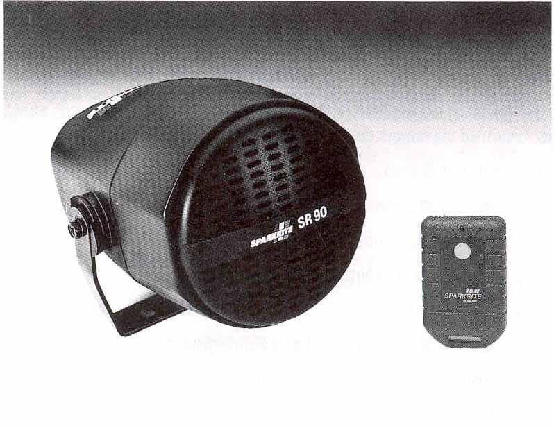
2 SPARKRITE SR90 REMOTE CAR ALARM SYSTEM INTRODUCTION The Sparkrite SR90 advanced remote control alarm system incorporates the latest "state-of-the-art" microprocessor technology offering the ultimate in product reliability and performance. Features: Radio remote control-dti approved. Instant arming and disarming. Remote control panic feature-gives personal protection sounding siren for up to 50 seconds. Automatic (passive) arming feature. Alarm arms automatically 20 seconds after last door closure. Disarmed via remote control or ignition key. Powerful built-in 128dB siren. Current sensing-detects interior light switching on. Door switch sensing detects opening of doors, boot or bonnet. Hazard lights flash and siren chirps on arm/disarm. Audible chirp over-ride option. Alarm armed LED (light emitting diode) as a visible deterrent. Cooling fan sensing circuit-prevents false triggering of current sensing circuit. Attempted entry display. LED flashes a code if vehicle has been tampered with. Siren sounds for 50 seconds (nominal) when the alarm is triggered. Automatic reset, giving continuous protection until disarmed by remote control. Fuse protected against attempts to over-ride circuitry. Sensor connection (optional)-quick-fit plug allows connection of Sparkrite Ultrasonic Interior Protection unit SR901 or Space Sensor SR902. Security circuit-prevents accidental arming whilst driving. 2
3 REMOTE CONTROL RADIO TRANSMITTER The radio transmitter conforms to DTI legislation with each alarm allocated a unique security code. Additional transmitters are available on special order from your nearest stockist, or direct from Sparkrite using the enclosed order form, quoting your serial number on the back of the remote control. ARMING To arm the SR90 alarm, proceed as follows: Remove the ignition key and leave the vehicle ensuring all doors, windows, sunroof, boot and bonnet are closed. Press the button on the remote control transmitter once. The indicators on the vehicle will flash once, coinciding with a single chirp (if selected) from the siren, and the dashboard LED will also flash (following the 20 second arming delay), at approximately one second intervals to show that the system is armed. If passive arming is selected, the SR90 will arm automatically following closure of the last door (see arming control). DISARMING To disarm the alarm, press the transmitter button once, the indicators will flash three times, coinciding with two chirps (if selected) from the siren. Check that the dashboard LED has stopped flashing and unlock the vehicle as normal. If you trigger the alarm accidentally, follow the normal disarming procedure but keep the control button depressed until the alarm stops. Note: When the alarm is armed, the current sensing and ultrasonic circuits (optional) will not trigger the alarm until a 30 second exit delay has expired. This is to allow movement inside the vehicle and in some cases, courtesy light delays to cease. REMOTE PANIC If the transmitter button is pressed and held for three seconds, the SR90 will trigger and commence an alarm cycle as a possible means of summoning help, a very useful defense in case of attack or assault. 3
4 FEATURE SELECTION The SR90 is specifically designed to give a choice of operating features for your convenience. These are three ON/OFF switches as follows: - 1. AUDIBLE CHIRP Controls arm/disarm chirp only. Turn to OFF for no audible chirp. 2. PASSIVE ARMING CONTROL If the passive (automatic) arming feature is required, select the ON position of the slide switch. With the switch in the ON position, the alarm will automatically commence the arming sequence 10 seconds AFTER the last door is closed, and will be fully armed after 20 seconds. The hazard lights will flash once and the siren will chirp, (if selected), indicating the vehicle is protected. The alarm is disarmed using the remote control as normal or by switching on the ignition within 10 seconds. In the OFF position, use the remote control for Instant ARM and DISARM. 3. CURRENT SENSING Current sensing is the most common method of triggering an alarm. This circuit operates by detecting the current drained from the vehicle's battery when the interior light is switched on, which subsequently triggers the alarm. When the SR90 is installed, it is recommended that the slide switch is set in the ON position. If your vehicle is fitted with an electrically operated, pulsed clockwork clock (normally fitted on vehicles pre 1980) or a car telephone which accepts incoming calls when the ignition is off, it can cause false triggering of the alarm. In this instance, slide the current sensing switch to the OFF position. It will then be necessary to connect the BLUE wire to the door switches as described later. IMPORTANT: The SR90 switches are factory set to the following positions: Current - ON Passive - OFF Chirp ON 4
5 FITTING INSTRUCTIONS Suitable for 12V negative earth vehicles only. IMPORTANT: The vehicle battery must be disconnected during the installation procedure, except where necessary to carry out circuit tests specified. TESTING PROCEDURE If you are unable to easily identify the correct wire on the vehicle to make a connection, it is recommended a 12 DC test lamp or test screwdriver is used. Care must be taken to ensure the wire being tested is not shorted to earth (chassis) via the wire or probe of the tester. INSTALLATION NOTES a) The harness is supplied with in-line fuses in the RED, VIOLET and GREY leads. If any of the fuses blow, ensure replacements of the correct value are used. b) When mounting wires around the engine compartment and through the bulkhead inside the vehicle, ensure the wire insulation cannot be damaged on sharp metal edges, protecting where necessary with insulation tape or rubber sleeving. c) It is recommended that where possible, connections to the vehicle wiring should be made at the steering column or fusebox. This will prevent anyone tampering with the alarm from outside the vehicle. d) Do not switch off courtesy, or boot lights (if fitted) or the current sensing circuit will not operate. Replace light bulbs when they fail. MOUNTING THE MAIN ALARM MODULE ~ Mount the alarm in the vehicle's engine compartment, close to the front of the vehicle and in a position where it is difficult to gain access to the alarm wiring from below the car. Also ensure the alarm is located away from areas of extreme heat and at least 12" away from the ignition system. Using the alarm mounting bracket as a template, drill 2 holes, and secure the bracket to the car bodywork using self-tapping screws supplied. 5
6 MAIN CABLE HARNESS WIRING Connections to the vehicle wiring will be made using scotchlok connectors as follows; ADDITIONAL WIRE Close the locking tab to hold the connector together METAL INSERT EXISTING WIRE STOP Place the wires in position as shown and hold carefully in place whilst pressing firmly in the metal insert with pliers. The metal insert automatically strips the insulation from wires at points of contact. HARNESS LOCATION Feed the 3 and 5 way harness through the flexible rubber sleeve and position the assembly to the rear of the main alarm module. IMPORTANT: Do not connect wiring harnesses to the alarm until all wiring has been connected. ARMED INDICATOR LED Remove the retaining nut from the LED bezel. Drill a suitable mounting hole in the dashboard where the armed indicator may be seen from outside the vehicle, as a visible deterrent. Feed the two way connector through the hole and secure the LED bezel with the retaining nut. Route the wires through a bulkhead grommet to the alarm and push them carefully through the flexible rubber sleeve. Insert the two way connector into the socket on the rear of the alarm. Operation: When the alarm is armed, the red LED will illuminate. Following the 20 second exit delay, the LED will flash at 1 second intervals to indicate the SR90 is fully armed. If the alarm is triggered and completes a full alarm cycle (50 seconds), the LED will flash at half second intervals to indicate that a violation has occurred. 6
7 WIRING DIAGRAM WIRING CONNECTIONS GREEN - RADIO AERIAL The GREEN aerial wire must not be cut or connected to anything metal, otherwise the operating range will be affected. Tape the antenna to the main harness to achieve optimum performance. VIOLET AND GREY-INDICATOR LIGHTS VIOLET Using the vehicle's wiring diagram or 12V test lamp, locate the wire on the indicator switch or direct on any indicator lamp, which illuminates the test bulb when the RIGHT hand indicator flashes on and off. Connect this wire to the VIOLET wire on the alarm harness using a scotchlock connector. GREY Repeat the above procedure, connecting the GREY wire to the LEFT hand indicator circuit. PINK -IGNITION INPUT Using a test lamp, locate a 12 volt supply wire at the ignition switch or fusebox which is live only in the STARTING and RUN positions of the ignition key. Connect the PINK wire using a scotchlock connector to this wire. Note: The auxiliary power supply to radios/cassettes must not be used. 7
8 YELLOW - ELECTRIC FAN INHIBIT If the cooling fan is switched by the ignition or no electric fan is fitted, insulate the YELLOW wire and leave disconnected. If your vehicle is fitted with a thermostatically controlled cooling fan which operates with the ignition switched off, the YELLOW lead must be connected to prevent false triggering of the alarm. The majority of modern vehicles have "positive" switched fans and the YELLOW wire should be connected as shown in Fig. 1. If the cooling fan is earth" switched as shown in Fig. 2, it will be necessary to slide the current sensing switch on the main alarm module to the OFF position, insulate the YELLOW wire and leave disconnected. BLACK WIRE EARTH The BLACK wire must be connected to a good clean metal earthing point on the bodywork of the vehicle. Drill a suitable hole within 12" of the main alarm unit and secure the BLACK wire through the ring terminal using the self-tapping screw supplied. 8
9 BLUE-DOOR SWITCHES If the vehicle is not fitted with courtesy light switches on the rear doors, it is recommended additional switches (SR910) are fitted and connected to the courtesy light circuit as shown in Fig. 3. If the current sensing switch on the main alarm is in the ON position, and your courtesy light works on all four doors, proceed to Section (ii) Boot and Bonnet Switches. If the current sensing switch is in the OFF position, it will be necessary to connect direct to the door switches. (i) Most four door cars operate the courtesy light from all four doors, so connecting the alarm to one door switch will connect all of the doors. The BLUE alarm wire should be connected to the existing door switches providing they are of the switched earth type. To determine this, close all doors except the driver's door. The courtesy light should be on. Remove the retaining screw from the door switch and carefully pullout the switch. If the interior light goes out when the door switch is removed, your existing courtesy light door switches are suitable for direct connection to the BLUE lead. The BLUE lead can then be connected to the door switch wire using a scotchlock connector. BOOT AND BONNET SWITCHES (OPTIONAL) (ii) To protect the boot and bonnet, it will be necessary to install additional pin switches (Sparkrite SR910) connected to the BLUE wire as shown in Fig 3. IMPORTANT: PASSIVE ARMING. THEBLUEWIREMUSTBECONNECTEDTOANYCOURTESYLIGHT SWITCH TO OPERATE THE PASSIVE (LAST DOOR) ARMING FEATURE. 9
10 RED WIRE - POWER SUPPLY/CURRENT SENSING The RED wire must be connected to a permanent 12 volt supply at the vehicle's fusebox (i.e. a fuse which is live whether the ignition is on or off). Using a test lamp, identify a permanently live fuse rated not less than 15 amps, and connect the RED lead to the "FUSED" side. To determine this, remove the selected fuse and check both fuse terminals with the test lamp. The correct side of the fuse will be "dead" when the fuse is removed. Connect the RED lead to the wire attached to the fuse terminal using a scotchlock connector. NOTE: The position of the supply lead affects the sensitivity of the current sense circuit. Connecting directly to battery positive will give lowest sensitivity. Connecting further away e.g. the fusebox, will increase sensitivity. SENSOR INPUT The SR90 sensor input is located on the rear of the main alarm control module. This enables direct connection of Sparkrite accessories SR901 Ultrasonic Interior Detector or SR902 Interior Space Sensor to further protect your vehicle. To connect either of the above accessories', feed the SR901 /SR902 connecting plug through the flexible rubber sleeve and push into the sensor socket located on the rear of the alarm module (shown on page 4). THE WIRING INSTALLATION IS NOW COMPLETE Connect the harness plug connectors into their respective sockets on the rear of the alarm. Reconnect the battery. Test the alarm according to your selected positions of the slide switches. If any problems are encountered, re-check the wiring and follow the troubleshooting guide. Slide the rubber sleeve over the rear molding shoulder and fit a cable tie around the flexible tube to provide weatherproofing. The exit tube should be angled downwards to avoid water ingress. BATTERY REPLACEMENT The battery needs replacing if the red BATTERY LEVEL INDICATOR does not light when the transmitter button is pressed. To replace this, remove two screws from the rear casing and carefully separate the transmitter molding. Replace with 12 volt Sparkrite battery, Part Number SR904 observing correct polarity. 10
11 TROUBLESHOOTING GUIDE REMOTE CONTROL TRANSMITTER Pressing button on remote control doesn't light transmitter indicator, next to button. Battery inserted wrongly. Poor battery connection. Adjust terminals to ensure good battery contact. Discharged or missing battery. Replace battery. ARMING AND DISARMING Pressing button on remote control lights transmitter indicator, but has no effect on receiver indicator. No power supply to alarm unit. Check wiring, fuse and using suitable tester, check that 12V is present on the RED wire. Distance between transmitter and receiver is too great. Move closer and try again. Pressing the button on the transmitter, but it is not possible to arm or disarm the alarm. Power supply present on the arming inhibit input (PINK wire) ignition switched on or wiring fault causing power to be present on this wire when ignition is switched off. Check using suitable tester. CURRENT SENSING With the slide switch in the ON position, operating the courtesy light by opening door doesn't activate the alarm. The courtesy light bulb has a low power rating. If the RED wire has been connected to the battery positive, remove it and increase the current sense sensitivity by connecting the RED wire at the fusebox or column switches. DOOR, BOOT, BONNET SWITCH INPUT Operating pin switch (contacts closed) doesn't activate alarm. Pin switch faulty. Use suitable tester to check switch operation. Wiring fault. Check wiring. Wrong polarity switching. Should be earth switched. Use suitable tester to check this, especially if wired to the courtesy light circuit. Insert separate door switches of correct polarity. OUTPUT When alarm is activated, indicator lights do not pulse on and off. Wiring fault or fuses blown in wiring harness. Check wiring and fuses. 11
12 ALARM GIVES FALSE ALARMS Bad earth or supply connection to main alarm unit causing current sense (if used) to false alarm. Check connection of BLACK wire to earth. Check connection of the RED supply wire from the connector. Current sense problem. Check that your vehicle has no accessories which can operate when the ignition is switched off. Wiring fault. Check all wiring, test operation of all switches and ensure all triggering connections are secure and make good electrical contact. If none of the above solutions solve the problem, either consult your dealer, or contact the Sparkrite Technical and After Sales Service (T.A.S.S.) on ACCESSORIES FOR THE SR9O ALARM Optional extra protection for your car can be provided by fitting either the SR901 or SR902: SR901 - ULTRASONIC INTERIOR PROTECTION Invisible ultrasonic waves are transmitted and received by a unit mounted on the dashboard inside your vehicle. The alarm is triggered by unauthorized entry through the doors, windows or sunroof. SR902 - SPACE SENSOR Mounted inside your car, this unique, patented product uses spaceage technology to detect alterations in atmospheric pressure. This results in the alarm being triggered if any doors, windows etc are opened. SR910 - DOOR/BOOT/BONNET SWITCHES ADDITIONAL TRANSMITTERS Available either from your local stockist or direct from Sparkrite. Please send a cheque or postal order to the value of inclusive payable to EDA Sparkrite Limited at the following address: STADIUM CONSUMER PRODUCTS STADIUM NORTH UNITS 8-11 TOFTS FARM INDUSTRIAL ESTATE BRENDA ROAD HARTLEPOOL CLEVELAND TS25 2DH QUOTE YOUR SERIAL NUMBER FROM THE REAR OF THE RANSMITTER AND SPECIFY MODEL OF ALARM. 12
-1- REMOTE CAR ALARM SYSTEM. Technical Help Line
 -1- REMOTE CAR ALARM SYSTEM Technical Help Line 01429 862616 Email- technical.support@stadiumcp.co.uk SRA8 FEATURES 2 radio remote controlled transmitters. DTI approved. Instant arm/disarm. Starter motor
INSTRUCTION MANUAL FOR. Remote Control Car Alarm with Impact Sensor, Mini-Battery Backup Siren & Engine Immobiliser
 INSTRUCTION MANUAL FOR Remote Control Car Alarm with Impact Sensor, Mini-Battery Backup Siren & Engine Immobiliser A.C.N 001 621 610 SYDNEY / AUSTRALIA Build Date: TO ARM/DISARM ALARM The alarm is activated
TO ARM/DISARM ALARM The alarm is activated by pressing BUTTON 1 on the remote control transmitter once. The blinkers will flash once, and the
 INSTRUCTION MANUAL FOR Code Hopping Remote Control Car Alarm with Two Stage Impact Sensor, Battery Backup Siren & 2 Point Engine Immobilisation N517 Build SYDNEY Date: / AUSTRALIA Version 2.0 TO ARM/DISARM
The most user friendly Security Alarm System L S Section 1 Overview of System Section 2 Planning your Installation
 The most user friendly Contents Section 1 Overview of System 1.1 Kit Contents 1.2 Tools Required 1.3 System Features Security Alarm System L S 4 0 0 Section 2 Planning your Installation 2.1 Location of
For silent arm / disarm use BUTTON 2.
 INSTRUCTION MANUAL FOR Code Hopping Remote Control Car Alarm with Two Stage Impact Sensor, Battery Backup Siren & 2 Point Engine Immobilisation A.C.N 001 621 610 SYDNEY / AUSTRALIA Build Date: TO ARM/DISARM
Model: M30. Owner s Operation Manual. For correct operation, please read this manual to familiarise yourself with the features.
 Model: M30 Owner s Operation Manual For correct operation, please read this manual to familiarise yourself with the features. Includes wiring diagram We recommend professional installation of this security
FOR MORE INFORMATION AND PRODUCTS, VISIT: USER MANUAL TO REMAIN IN VEHICLE
 poplocks.com Pro Controller I CODE LEARNING SEQUENTIAL LOCKING ZONE SECURITY DOOR OPEN WARNING FOR MORE INFORMATION AND PRODUCTS, VISIT: /fleetwood03.html Any questions please Email Support@poplocks.com
7590TK15 INSTALLATION AND USE MANUAL
 7590TK15 INSTALLATION AND USE MANUAL Made in Italy AC2594 Rev.02-06/14 UK TABLE OF CONTENTS 1.0 - PRELIMINARY ADVICE 2.0 - FUNCTIONS 3.0 - REMOTE CONTROL OPERATION AND BATTERY REPLACEMENT USER MANUAL 4.0
FOR MORE INFORMATION AND PRODUCTS, VISIT: USER MANUAL TO REMAIN IN VEHICLE
 SMART KEYLESS CODE LEARNING SEQUENTIAL LOCKING ZONE SECURITY FOR MORE INFORMATION AND PRODUCTS, VISIT: /fleetwood03.html Any questions please Email Support@poplocks.com All enquiries please reference Product
SR-i500 INSTALLATION MANUAL AND USER S GUIDE. FM 2-Way Security System. Setting Clock Time. Setting Alarm Clock. FCC Notice
 Setting Clock Time 1. Enter the programming mode. 2. Press button #4 repeatedly until the icon begins to flash. 3. Press button #1 to select and enter clock setting mode. 4. Press button #1 to scroll through
Protect anything, anywhere, anytime.
 Set-up Guide Protect anything, anywhere, anytime. cell burst Built-in Features www.tattletalealarm.com ALARM SYSTEM IN A BOX 1.2 watt Cellemetry radio PIR motion 115 db Siren Safety strobe light Lighted
Phoenix 2 Rev. A - Owner's Manual 0399
 Table of Contents Phoenix 2... 2 Lifetime Warranty...2 Remote Controls....2 Electronic Scan Prevention (ESP)... 3 Instant Remote Control Code Deletion... 3 One-Step Remote Control Code Learning... 3 Valet
Power Locking Installation Manual
 Shop Manual V203 Please Copy Necessary Pages, and Store the Original Power Locking System PLRB-Pro Controller Flex Switch & Key Fobs Numeric Keyless Interface Power lock (Compartments) Power Locking Installation
IDM4 CARAVAN ALARM. Operating instructions
 IDM4 CARAVAN ALARM Operating instructions Factory Settings Entry Delay - 0:00 (0 secs) Exit Delay - 0:20 (20secs) Siren On Time - 1:00 (1 minute) Manufacturers Personal Code - 1234 Operation Alarm Keypad
AMX 68 Owner's Manual 12/29/97
 Standard Features Lifetime Warranty We guarantee the operation of the control unit and remote controls for as long as you own your car (see the enclosed warranty card for details). A Pair of AviGlo 3-Button/6-Channel
/ /24 INSTALLATION AND USE MANUAL. Made in Italy AC 2710/UK Rev /12
 INSTALLATION CERTIFICATE The undersigned qualified installer attests to have personally fitted the here described vehicle security system following the manufacturer instructions. By : Sold on : T ype of
G34 AU1B (External Ultrasonic Sensor) Version 3
 Version 3") Car Alarm Series 3 B 4 Buttons G34 AU1B (External Ultrasonic Sensor) Version 3 24 CAR ALARM GENIUS Series 3B 4 Buttons G34 AU1B (External Ultrasonic Sensor) Module controlled using Micro-Processor 2 Transmitters
Car Alarm Series 3 B 4 Buttons G34 AU1B (External Ultrasonic Sensor) Version 3 24 CAR ALARM GENIUS Series 3B 4 Buttons G34 AU1B (External Ultrasonic Sensor) Module controlled using Micro-Processor 2 Transmitters
cod.: ISUT211/211BUK-UK FILENAME:ISUT211/211BUK-UK.P65 211UK -211BUK MODULAR ALARM SYSTEMS USER GUIDE CAR ALARM SYSTEMS
 cod.: ISUT211/211BUK-UK FILENAME:ISUT211/211BUK-UK.P65 GB 211UK -211BUK MODULAR ALARM SYSTEMS USER GUIDE CAR ALARM SYSTEMS THE SYSTEM IS MANUFACTURED FROM THE HIGHEST QUALITY COMPONENTS TO ENSURE A LONG
MEGA WAY LCD 4-CHANNEL MOTORCYCLE ALARM SECURITY SYSTEM. Operation Manual MEGATRONIX CALIFORNIA, U.S.A. MEGA 3100 OPERATE 1
 MEGA 3100 2-WAY LCD 4-CHANNEL MOTORCYCLE ALARM SECURITY SYSTEM Operation Manual MEGATRONIX CALIFORNIA, U.S.A. MEGA 3100 OPERATE 1 MEGA 3100 OPERATE 2 A. TRANSMITTER OPERATION: OPERATION: Transmitter Button
Fitting Instructions: Street Triple Rx, Daytona 675 from VIN and Daytona 675 R from VIN A
 English Fitting Instructions: Street Triple Rx, Daytona 675 from VIN 564948 and Daytona 675 R from VIN 564948 A9808114 Thank you for choosing this Triumph genuine accessory kit. This accessory kit is the
M60 Series WITH BUILT-IN TURBO TIMER. OWNERS OPERATION MANUAL includes programming and wiring information
 M60 Series M60i M60B, M60S M60G/GNZ 3 STAR 4 STAR 5 STAR WITH BUILT-IN TURBO TIMER OWNERS OPERATION MANUAL includes programming and wiring information All models certified to AS/NZS4601 amendment 1 2003
Premium 8 Zone Wireless Alarm Kit
 Premium 8 Zone Wireless Alarm Kit INTRODUCTION The wireless alarm system is designed to protect your home. It is a simple to use, easy to install unit. No special tools or training are required, all fixings
Alarm System SECURE AS 302
 Alarm System SECURE AS 302 Operating Manual SECURE Light app now available! Table of Contents Before You Start.................................. 4 User Information....................................4
5000 SERIES 8 ZONE INSTRUCTION MANUAL
 5000 SERIES 8 ZONE INSTRUCTION MANUAL NESS SECURITY PRODUCTS 4/167 PROSPECT HIGHWAY SEVEN HILLS. 2147 NSW AUSTRALIA SYDNEY Phone: (02) 8825 9222 (Head Office) BRISBANE Phone: (07) 3343 7744 MELBOURNE Phone:
Contents. Glossary
 Contents Glossary ------------------------------------------------------------------------------------------------------ 6 1. Introduction to the IDS 1632 -------------------------------------------------------------
Model 700 ESP Owner's Guide
 Model 700 ESP Owner's Guide Table of Contents Standard Transmitter Configuration............................... 2 What Is Included............................................. 3 Important Information.........................................
What you get Welcome to the best generation of security with remote start. Your system contains everything you need.
 Congratulations Congratulations on the purchase of your state-of-the-art remote start and security system. Reading this Owner s Guide prior to using your system will help maximize the use of your system
Solution 880 Operators Manual. Issue 1.00
 Solution 880 Operators Manual Issue 1.00 Solution 880 Operators Manual Copyright 1998 by, SYDNEY, AUSTRALIA Document Part Number MA408O Document ISSUE 1.00 Printed 15 June 1998 This documentation is provided
Solution Ultima 862 Operators Manual ISSUE 1.10
 Solution Ultima 862 Operators Manual ISSUE 1.10 Solution Ultima 862 Operators Manual Copyright 2001 by, SYDNEY, AUSTRALIA Document Part Number MA486O DOCUMENT ISSUE 1.10 Printed 24 April 2001 This documentation
TS400 & TS410. Intruder Alarm Control Panels. Operating Instructions
 TS400 & TS410 Intruder Alarm Control Panels Operating Instructions Zone Location Home Set Chime 1 Armed / Omitted 2 Armed / Omitted 3 Armed / Omitted 4 Armed / Omitted 5 Armed / Omitted F. Exit Always
Solution 844 Operators Manual ISSUE 1.10
 Solution 844 Operators Manual ISSUE 1.10 Solution 844 Operators Manual Copyright 2001 by, SYDNEY, AUSTRALIA Document Part Number MA406O DOCUMENT ISSUE 1.10 Printed 24 April 2001 This documentation is provided
Solution Ultima Series Operators Manual ISSUE 1.00
 Solution Ultima Series Operators Manual ISSUE 1.00 Solution Ultima Series Operators Manual Copyright 1998 by, SYDNEY, AUSTRALIA Document Part Number MA488O DOCUMENT ISSUE 1.00 Printed 16 February 1999
Premier Hazard STC Instructions
 PREMIER HAZARD Ltd Bessingby Industrial Estate Bridlington YO16 4SJ Tel: +44 (0) 113 239 1111 Fax: +44 (0) 113 239 1131 www.premierhazard.co.uk info@premierhazard.co.uk Premier Hazard STC Instructions
ENFORCER OWNER'S MANUAL. SLI 840 / SLI 840C (315 MHz) SLI / SLI 840C-4 ( MHz) Remote Controlled Keyless Entry System with Alarm
 SLI / SLI 840C-4 ( MHz) Remote Controlled Keyless Entry System with Alarm") OWNER'S MANUAL ENFORCER SLI 840 / SLI 840C (315 MHz) SLI 840-4 / SLI 840C-4 (433.92 MHz) Remote Controlled Keyless Entry System with Alarm SECO-LARM U.S.A., INC. 16842 Millikan Avenue, Irvine, California
OWNER'S MANUAL ENFORCER SLI 840 / SLI 840C (315 MHz) SLI 840-4 / SLI 840C-4 (433.92 MHz) Remote Controlled Keyless Entry System with Alarm SECO-LARM U.S.A., INC. 16842 Millikan Avenue, Irvine, California
640 Series Advanced Remote Vehicle Security System
 640 Series Advanced Remote Vehicle Security System WWW.ULTRASTARTERS.COM FCC/ID Notice This device complies with Part 15 of the FCC rules. Operation is subject to the following conditions: (1) This device
Watchguard WGAP864 User Manual
 Watchguard WGAP864 User Manual v1.0 Issued September 2016 1 2 Table of Contents Glossary... 5 1. Introduction to your Watchguard WGAP864... 6 2. Before Operating your Alarm System... 6 3. Understanding
USER GUIDE WIRE-FREE HOME PROTECTION SYSTEM AG100+ CONTENTS
 CONTENTS USER GUIDE WIRE-FREE HOME PROTECTION SYSTEM AG00 Section Getting started. General system overview. Introduction to the system. Items included with the system. Introduction to the Smart Panel.5
670T INSURANCE APPROVED CAN BUS ALARM (ORIGINAL REMOTE CONTROL UPGRADE) USER GUIDE
 USER GUIDE") GB 670T INSURANCE APPROVED CAN BUS ALARM (ORIGINAL REMOTE CONTROL UPGRADE) USER GUIDE CAR ALARM SYSTEMS ISUT670T.p65 1 pag. 2 ENGLISH 1 - INDEX 1) Index... 2 2) Introduction... 3 3) 670T System Components...
GB 670T INSURANCE APPROVED CAN BUS ALARM (ORIGINAL REMOTE CONTROL UPGRADE) USER GUIDE CAR ALARM SYSTEMS ISUT670T.p65 1 pag. 2 ENGLISH 1 - INDEX 1) Index... 2 2) Introduction... 3 3) 670T System Components...
Remote Vehicle Control System. Security and Convenience System
 1 Remote Vehicle Control System PC 4300 TM Owner's Manual Security and Convenience System IMPORTANT NOTE: The operation of the PowerCode as described in this manual is applicable to most vehicles. However,
OWNER S MANUAL. Remote Mobile Security System. Models: PL50 PL60
 Remote Mobile Security System OWNER S MANUAL Models: PL50 PL60 This device complies with part 15 of the FCC rules. Operation is subject to the following two conditions: (1) This device may not cause harmful
Installation & Programming Guide
 Alert Version 8 Zone Control Arrowhead Alarm Products Ltd Installation & Programming Guide Proudly Designed and Manufactured in New Zealand Arrowhead Alarm Products Ltd PHONE: (09) 579 7506 FAX: (09) 579
Supervised Security System Owner's Guide
 Owner's Guide PSC06 READ THIS FIRST This equipment generates and uses radio frequency energy, and if not installed and used properly, that is, in strict accordance with the manufacturers instructions,
What you get Welcome to the best generation of security with remote start. Your system contains everything you need.
 Congratulations Congratulations on the purchase of your state-of-the-art remote start and security system. Reading this Owner s Guide prior to using your system will help maximize the use of your system
PRO-TEC SYSTEM ONE. Trailer Security Systems Model # PTS-2. Photo includes PTS-2 with optional pager unit
 PRO-TEC SYSTEM ONE Trailer Security Systems Model # PTS-2 Photo includes PTS-2 with optional pager unit Professional Technology to Pro-Tec Your Investment More helpful install information on our website
MOBILE CALL GSM Alarm System User s Manual
 MOBILE CALL GSM Alarm System User s Manual Profile For a better understanding of this product, please read this user manual thoroughly before using it. Contents Function Introduction (3) Alarm Host Diagram
LS800S Intruder Alarm System. Engineering Manual
 LS800S Intruder Alarm System Engineering Manual Table of Contents Section 1 Overview of System 1.1 Kit Contents 1.2 Tools Required 1.3 System Features Section 2 Planning your installation 2.1 Location
Model AM1 Owner s Guide
 Model AM1 Owner s Guide limited lifetime consumer warranty Directed Electronics, Inc. promises to the original purchaser to repair or replace with a comparable reconditioned model any Directed Electronics,
745i 3 OPERATION MANUAL TABLE OF CONTENTS
 TABLE OF CONTENTS OPERATION MANUAL 745i 3 COPYRIGHT 1999: OMEGA RESEARCH & DEVELOPMENT, INC. About Your New Crime Guard System... 3 Using Your Crime Guard System... 4 Remote Arming By Transmitter... 4-5
Intelligent Security & Fire Ltd
 OPERATIONAL NOTES FOR CONCEPT FIRE PANEL. NOTE ON NEW FIRE PANELS, POSITION 1 ON THE SIX WAY INTERNAL OPTION SWITCH IS TURNED ON, DISABLING THE ZONAL SOUNDERS. TO ENABLE ZONAL SOUNDERS TURN OFF. Operation
Quick Installation Manual LED 99-Zone Autodial Wireless Alarm System
 Quick Installation Manual LED 99-Zone Autodial Wireless Alarm System By shield4u http:// (Version 20130211) A. Alarm Understanding Wireless Antenna Display Keypad Indicator Function Keys Switch for Backup
USER MANUAL CEF AP28 CONTROL PANEL
 USER MANUAL CEF AP28 CONTROL PANEL AP28 WARNINGS This product has mains voltage present within the housing. Please take the necessary precautions in not allowing any liquid to spill on or into the housing.
Installation, Operating and Maintenance Manual
 STATUS ZONES CONTROLS FIRE FAULT DISABLED FIRE 1 2 3 4 5 6 7 8 TEST FAULT DISABLED 1 5 BUZZER SILENCE RESET 1 2 TEST 2 6 LAMP TEST 3 SUPPLY 3 7 SYSTEM FAULT 4 8 SOUNDERS ACTIVATE/ SILENCE 4 FAULTS INSTRUCTIONS
NO ONE DARES COME CLOSE O WNER S GUIDE 7756V
 NO ONE DARES COME CLOSE O WNER S GUIDE M O D E L 7756V Congratulations Congratulations on the purchase of your state-of-the-art Directed Digital System. Reading this Owner s Guide prior to using your
PNC 1000 SERIES 2, 4, 8 Zone Fire Alarm Control Panel
 PNC 1000 SERIES 2, 4, 8 Zone Fire Alarm Control Panel INSTALLATION, OPERATION AND MAINTENANCE MANUAL Version: CN-PM-1000.VER1.1-12/2012 EN54 INFORMATION In accordance with EN 54-2 clause 13.7, the maximum
9000P Wireless Alarm Owner s Manual
 9000P Wireless Alarm Owner s Manual Table of Contents Introduction... 3 Intended Use... 3 System Functionality... 3 Arming your Alarm... 3 Arm Home...3 Arm Away...4 Alarm Triggering... 4 Disarming your
LeakSafe. solutions. WaterSwitch2. Installation Instructions
 LeakSafe solutions TM WaterSwitch2 Installation Instructions WATERSWITCH2 COMPONENTS WaterSwitch2 Valve Control Extended Range Valve Driver Valve Water Flow Sensor Leak Detection tape available in 0.3M
User s Information Guide R2A
 Pi HSC505 Home Security Controller User s Information Guide R2A Page 1 of 15 of its development program. 1This document and product are copyrighted and all rights are reserved. Introduction Convention
ARROWHEAD ALARM PRODUCTS Ltd. 344b Rosedale Rd, Albany, Auckland. Ph Fax v1.0
 ARROWHEAD ALARM PRODUCTS Ltd. 344b Rosedale Rd, Albany, Auckland. Ph. 09 414 0085 Fax. 09 414 0088 www.aap.co.nz v1.0 Zone Trouble Shooting (single EOL) = = = = RED, RED, RED, GOLD. = YELLOW, VIOLET, RED,
DL150 DOWNLOADABLE CONTROL COMMUNICATOR INSTALLATION MANUAL
 DL150 DOWNLOADABLE CONTROL COMMUNICATOR INSTALLATION MANUAL TABLE OF CONTENTS 1. GENERAL DESCRIPTION... 2 2. STANDARD AND OPTIONAL PARTS LIST... 2 3. FEATURE DEFINITIONS... 3 4. TERMINAL DRAWING AND SPECIAL
AXI LED USER MANUAL (REV. 1.0)
") Security & Home Automation System AXI LED USER MANUAL (REV. 1.0) CONTENTS PREFACE FEATURES LED KEYPAD OUTLOOK 1.0 LIGHT INDICATION 1 2 4 6 CHAPTER 1: ALARM SYSTEM CONTROL 1.0 USING LED KEYPAD 1.0.1 ARMING
Security & Home Automation System AXI LED USER MANUAL (REV. 1.0) CONTENTS PREFACE FEATURES LED KEYPAD OUTLOOK 1.0 LIGHT INDICATION 1 2 4 6 CHAPTER 1: ALARM SYSTEM CONTROL 1.0 USING LED KEYPAD 1.0.1 ARMING
DETECTOR TRANSMITTER INSTALLATION & OPERATING. Cat No. TLTX2000B INSTRUCTIONS
 DETECTOR TRANSMITTER Cat No. TLTX2000B INSTALLATION & OPERATING INSTRUCTIONS 1 Introduction The TLTX2000B Controller Transmitter is part of the Timeguard range of PIR products which communicate by radio
Important information. Government Regulations and Safety information. Your Warranty. Replacement remote controls
 Congratulations Congratulations on the purchase of your state-of-the-art security and remote start system. Reading this Owner s Guide prior to using your system will help maximize the use of your system
Thank you for choosing Ideal Security s Home Security System with Telephone Dialer.
 SK618 WIRELESS ALARM SYSTEM WITH AUTO DIALER OWNER'S MANUAL Thank you for choosing Ideal Security s Home Security System with Telephone Dialer. If at any time during your installation you have any questions
ANALOX 5001 Carbon Dioxide Monitor. User Manual ANALOX Analox 5001 Carbon Dioxide Monitor User Manual
 ANALOX 5001 ANALOX 5001 Carbon Dioxide Monitor User Manual Analox Sensor Technology Ltd 15 Ellerbeck Court, Stokesley Business Park North Yorkshire, TS9 5PT T: +44 (0)1642 711400 F: +44 (0)1642 713900
IDS816 User Manual H Issued January 2009
 1 Contents Glossary-------------------------------------------------------------------------------------------------------------------6 1. Introduction to the IDS 816---------------------------------------------------------------------------7
2006 directed electronics
 Model 3002 Owner s Guide limited lifetime consumer warranty Directed Electronics ("Directed") promises to the original purchaser to repair or replace with a comparable reconditioned model any Directed
LeakSafe. solutions. WaterSwitch2. Installation Instructions
 LeakSafe solutions TM WaterSwitch2 Installation Instructions QUICK USER GUIDE 1. Turning water ON or OFF using the WaterSwitch Valve Control To turn the water ON, press and hold down the WATER ON button
Power Wave. 8 Zone Control Communicator. Crow Electronic Engineering P/L. Ver:8.54. Installation & Programming Guide.
 Power Wave 8 8 Zone Control Communicator Crow Electronic Engineering P/L Ver:8.54 Installation & Programming Guide 8 November 2000 Crow ( Aust ) Electronic Engineering Pty Ltd Corporate Head Office: 429
CA 120 Owners Manual of 10
 CA 120 Owners Manual 1 of 10 Your System has many features and available options some of which are selected at time of installation. Consult your installing dealer for options that may have been installed
BF5000NT BF5000 EF2604 SF2603 DF2603
 PARTS & SERVICE MANUAL FOR THE 26 FIREPLACE MODEL NUMBER: BF5000NT BF5000 EF2604 SF2603 DF2603 7400520000R03 TABLE OF CONTENTS Table of Contents OPERATION... 2 EXPLODED DIAGRAM... 4 WIRING DIAGRAM... 5
AVS S5 Alarm Anniversary Model
 www.avscarsecurity.com AVS S5 Alarm Anniversary Model Owner s manual Thank you for choosing an AVS S-Series car security system. The AVS S5 is engineered to the highest specifications providing you with
e-ask electronic Access Security Keyless-entry
 e-ask electronic Access Security Keyless-entry e-fob RF Keyless-entry entry Full Function Consumer Manual FCC ID: TV2EFOB1 (UM19 ~ 22793-01) Table of Contents Introduction... 1 e-fob Operation and Features
NO ONE DARES COME CLOSE O WNER S GUIDE 7857V
 NO ONE DARES COME CLOSE O WNER S GUIDE M O D E L 7857V Congratulations Congratulations on the purchase of your state-of-the-art Directed Digital System. Reading this Owner s Guide prior to using your
Model 3901T / 3902T / 3903T
 Vehicle Security System Model 3901T / 3902T / 3903T Owner s Guide Limited consumer warranty For a period of one calendar year from the date of purchase of this auto-security device, Directed Electronics,
GSM RFID VOICE Alarm System
 GSM RFID VOICE Alarm System User s Manual For a better understanding of this product, please read this user manual thoroughly before using it. CONTENTS [Function Instruction] [Control Panel] Control Panel
Service Manual 26 Self Trimming Fireplace with 3 Stage Remote
 Service Manual 26 Self Trimming Fireplace with 3 Stage Remote Model Number: DF2690 MOD: 0 Dimplex North America Limited 1367 Industrial Road Cambridge ON Canada N1R 7G8 1-800-668-6663 www.dimplex.com REV
DESTINY OWNER S MANUAL
 DESTINY OWNER S MANUAL DESTINY You have made a wise decision to protect your family and property with the DESTINY Security System. The DESTINY has been designed to provide you with a maximum level of security
System. For a better understanding of this product, please read this user manual thoroughly before using it.
 GSM Alarm System User s Manual For a better understanding of this product, please read this user manual thoroughly before using it. Chapter 1. Features Chapter 2. Control Panel Introduction Chapter 3.
Control/Communicator Installation Manual
 DAS NETWORX NX-12 Control/Communicator Installation Manual General Description...2 Ordering Information...2 Option Definitions...3 Programming the LED Code Pads...5 Programming the NX-12...9 Types of Programming
MAG2/4. AL MAG2 Soft. Version 2.1 MAG4 Soft.Version 2.0 USER MANUAL
 FIRE CONTROL PANEL MAG2/4 USER MANUAL AL MAG2 Soft. Version 2.1 MAG4 Soft.Version 2.0 READ THIS MANUAL BEFORE CONNECTING THE EQUIPMENT AND KEEP IT SAFE FOR FUTURE REFERENCE. To call our technical support
Contents. Glossary Introduction to the IDS Notes Understanding the Keypad Indicators Operation of the Keypad...
 2 Contents Glossary...7 1. Introduction to the IDS805...8 1.1 Notes...8 2. Understanding the Keypad Indicators...8 3. Operation of the Keypad...9 4. System Information...10 4.1 Programmed Functions...10
Freightliner Refrigerator Troubleshooting Guide For (TJ18F) (TJ22F) (TJ18FP3)
 (TJ22F) (TJ18FP3)") www.dometic.com Freightliner Refrigerator Troubleshooting Guide For Before initiating troubleshooting, the following equipment is recommended: Multimeter, 20 gauge (min) wires to use as jumpers, and 12Vdc
www.dometic.com Freightliner Refrigerator Troubleshooting Guide For Before initiating troubleshooting, the following equipment is recommended: Multimeter, 20 gauge (min) wires to use as jumpers, and 12Vdc
installation & operation manual
 installation & operation manual TABLE OF CONTENTS INTRODUCTION... 2 FEATURES... 2 PROGRAMMING CONTACT ID... 3 INSTALLATION... 3 OPENING THE HAWK COVER... 3 POWER SUPPLY... 5 CHECK AC... 5 DRY CONTACTS
460H INSTALLATION & OPERATION MANUAL REMOTE STROBE POWER SUPPLY IMPORTANT: 460H TM REMOTE STROBE POWER SUPPLY
 INSTALLATION & OPERATION MANUAL 460H TM REMOTE STROBE POWER SUPPLY 460H REMOTE STROBE POWER SUPPLY Contents: Introduction... 2 Standard Features... 2 Specifications... 2 Unpackaging & Pre-installation...
3 ZONE WIREFREE BURGLAR ALARM INSTALLATION & OPERATING INSTRUCTIONS
 WIREFREE PIRs WIREFREE KEYPAD AND CASE WIREFREE REMOTE WIREFREE DOOR CONTACT ukpanels.com Please note: Before you start to install this Micromark Alarm, we advise that you should take adequate safety precautions
IMPORTANT SAFEGUARDS READ AND FOLLOW ALL SAFETY INSTRUCTIONS. HZM-Series-Class I, Div 2 Battery Unit. Instalation instructions
 HZM-Series-Class I, Div 2 Battery Unit HZM-Series-Class I, Div 2 Battery Unit Instalation instructions IMPORTANT SAFEGUARDS 1 4 5 6 7 13 When using electrical equipment, basic safety precautions should
STERLING 10 Control Panel with Remote Keypads ICON and LCD INSTALLATION MANUAL
 STERLING 10 Control Panel with Remote Keypads ICON and LCD INSTALLATION MANUAL IMPORTANT: Please note the Sterling 10 LCD keypad is not compatible for use with the Sterling 10 ICON keypad. RINS1413-1 Pyronix
INSTALLATION AND USE MANUAL
 953 INSTALLATION AND USE MANUAL GEMINI Technologies S.p.A. Via Luigi Galvani 12-21020 Bodio Lomnago (VA) - Italia Tel. +39 0332 943211 - Fax +39 0332 948080 www.gemini-alarm.com ISO 9001 Certified Company
380 SERIES REMOTE SIREN ETSA380R
 ! WARNING Sirens produce loud sounds that may damage hearing: - Roll up windows. - Wear hearing protection. - Use only for emergency response. - Avoid exposure to siren sound outside of vehicle. Please
"Pegaso" wireless alarm system
 "Pegaso" wireless alarm system Summary Page 1.0. Description... 2 2.0. Installation... 3 3.0. Connections to mains power... 4 4.0. Low battery signalling... 4 5.0. Service key... 5 6.0. Selection of functions...
INSTRUCTION MANUAL FOR: WIRELESS SECURITY STARTER KIT MODEL NO: SWSKIT
 INSTRUCTION MANUAL FOR: WIRELESS SECURITY STARTER KIT MODEL NO: SWSKIT B. Operation i. Powering up the Key Fob Remote Control ii. Enrolling the Remote Control onto the Smart Panel iii. Operating the Key
DESTINY 6100 SERIES SECURITY SYSTEM OWNER S MANUAL V1 12/01
 DESTINY 6100 SERIES SECURITY SYSTEM OWNER S MANUAL 800-6006V1 12/01 System Overview General Information Control Panel Detection Devices You have made a wise decision to protect your family and property
IDS S E C U R I T Y IDS816. User Manual MANUAL NO C ISSUED APRIL 2005 VERSION 2.00
 INHEP DIGITAL IDS S E C U R I T Y IDS816 User Manual MANUAL NO. 700-283-01C ISSUED APRIL 2005 VERSION 2.00 Contents 1. Introduction to the IDS816... 4 2. Understanding the Keypad Indicators... 4 3. Programmable
Installation and Operation Guide for the UPS-64C Power Supply with CometFlash
 ENGINEERING COMPANY INC. ROUTE 45, WINTHROP ROAD CHESTER, CONNECTICUT 064-0684 TELEPHONE: (860) 56-9504 FAX: (860) 56-4078 Installation and Operation Guide for the UPS-64C Power Supply with CometFlash
Scantronic Leading the way in security
 USER GUIDE (16 ZONE) HARDWIRED CONTROL PANEL Scantronic Leading the way in security Contents 1. Introduction 3 The 9800+ (16 zone) System... 3 The Keypad... 3 About This Guide... 5 2. Everyday Operation
RANGER 7600 DOWNLOADABLE CONTROL COMMUNICATOR INSTALLATION MANUAL
 RANGER 7600 DOWNLOADABLE CONTROL COMMUNICATOR INSTALLATION MANUAL TABLE OF CONTENTS 1. TABLE OF CONTENTS... P.1 2. GENERAL DESCRIPTION... P.2... 3. STANDARD AND OPTIONAL PARTS LIST... P.2... 4. FEATURE
Advantage 6 Alarm Panel
 Issued ugust 1997 9778 Instruction Leaflet dvantage 6 larm Panel Introduction The control panel is designed to be simple to install, programme, and to use. The 16 button keypad allows you to select, change,
HA-263K HA-263D. OWNER'S MANUAL Installation And Operation 8-ZONE ALARM CONTROL PANEL FOR HOME AND OFFICE PROTECTIONS OPEN THE CABINET FOR SERVICE
 D (OPERATION) INITIATE A DYNAMIC BATTERY TEST The system tests the back-up battery once every 24 hours. The owner can initiate a dynamic battery test at any time with the following codes while the system
WIRELESS WaterSwitch
 WIRELESS WaterSwitch INSTALLATION & USER GUIDE SECTION 1 - LeakSafe WaterSwitch Components Water Valve Control and 4 x AA batteries Wireless Switch Motorised Valve and integrated cable LeakDetector Tab,
HSA % wirefree security alarm system. Installation Programming Operating. Helpline Intelligent Security & Fire Ltd
 HSA3000 100% wirefree security alarm system Installation Programming Operating Keep in a handy place for reference and for future maintenance Helpline 01902 635998 Introduction General system overview