HeartWare HVAD System. Patient Manual
|
|
|
- Loreen Cooper
- 5 years ago
- Views:
Transcription


1 HeartWare HVAD System Patient Manual
2 Quick Reference Guide for Alarms When an alarm occurs, two lines of text appear in the Controller Display. The first line tells you what the alarm is, and the second line tells you what to do. The chart below shows all potential alarms you may see on your controller. Alarm Type Alarm Display (Line 1) Action (Line 2) [no message] [no message] [No Power] Alarm When both power sources (2 batteries or 1 battery and an AC adapter or DC adapter) are removed, NO message will display on the controller. The [No Power] alarm will sound but the Alarm Indicator on the controller WILL NOT light. This indicates your pump has stopped. You should immediately connect two power sources. [VAD Stopped] [Connect Driveline] High Critical (Flashing Red) [VAD Stopped] [Change Controller] [Critical Battery] [Replace Battery 1] [Critical Battery] [Replace Battery 2] [Controller Failed] [Change Controller] [Controller Fault] [Call] [Controller Fault] [Call: ALARMS OFF] Medium (Flashing Yellow) [High Watts] [Electrical Fault] [Call] [Call] [Low Flow] [Call] [Suction] [Call] [Low Battery 1] [Replace Battery 1] Low (Solid Yellow) [Low Battery 2] [Replace Battery 2] [Power Disconnect] [Reconnect Power 1] [Power Disconnect] [Reconnect Power 2]
3 Contact Information All problems should be promptly reported to your clinician. Before you leave the hospital, add names and contact information below. It is very important to keep this information available in case something happens to you or to your HeartWare HVAD System. CLINICIAN CONTACT Name Name Office Office Pager Pager Mobile Mobile Implanting Hospital Name Address Implant Surgeon Name Phone Number AMBULANCE Company Phone Number
4 1 Introduction Table of Contents 1.0 Introduction Why You Should Read this Manual Heart Failure Overview Considering VAD Therapy Understanding How the HeartWare HVAD System Works Potential Complications and Risks Potential Benefits How to Decide if the HeartWare HVAD System is the Right Treatment for You Summary of Clinical Study Information Using the HeartWare HVAD System HeartWare HVAD System Overview Identifying the Components of the HeartWare HVAD System Warnings and Precautions Essential Performance The Operation to Place the HeartWare HVAD System Handling HeartWare HVAD System Components How the Controller Works Making Connections Driveline Connection Power Source Connections Changing Power Sources Using Battery Power Changing Battery Battery Charger Setting Up Your HeartWare HVAD System Carrying Cases How Long HeartWare HVAD System Equipment Should Last Emergencies and Alarms Handling an Emergency Overview of Alarms [No Power] Alarm High Alarms Medium Alarms Low Alarms Multiple Alarms How to Silence (Mute) Alarms Changing Controller to Back-Up Controller... 48
5 1 Table of Contents (continued) Introduction 5.0 Preparing for Discharge Equipment Needed to Go Home Discharge Instructions Patient and Caregiver Training (No Answers) The test with answers is located in the Appendix 6.0 Living with the HeartWare HVAD System Medications Understanding and Preventing Electrostatic Discharge (ESD) Exit Site Care Washing and Showering Loading the Shower Bag Traveling and Transport Caring for HeartWare HVAD System Equipment General Care Care of Your Controller Care of Your Batteries Care of Your Battery Charger Care of Your Carry and Shower Bags Glossary Glossary of Terms Appendix Answers to Patient and Caregiver Training... 84
6 1 Introduction Notes
7 HeartWare HVAD System 1.0 Introduction 1.1 Why You Should Read this Manual Heart Failure Overview Considering VAD Therapy Understanding How the HeartWare HVAD System Works Potential Complications and Risks Potential Benefits How to Decide if the HeartWare HVAD System is the Right Treatment for You Summary of Clinical Study Information Using the HeartWare HVAD System...6 1
8 1.0 Introduction 1.1 Why You Should Read this Manual This manual is intended for patients and caregivers. It will tell you about your HeartWare HVAD System and explain how it works. It also provides information about proper care of the HeartWare HVAD System and what to do in case of an emergency. In addition to this manual, your clinician will provide you with instructions on operating the HeartWare HVAD System and on necessary medical care. Prior to leaving the hospital you should understand how the HeartWare HVAD System works, how to care for the equipment and what to do in emergency situations. If you have any questions after reading this manual, please ask your clinician. WARNING! Please read this entire manual before using the HeartWare HVAD System outside of the hospital. It is not safe to use the system away from trained professionals until you understand the information in this manual. Symbols found in this manual Indicates there is more information available in the manual and will provide details as to where to find it. Identifies the information as a Warning. A Warning is a statement about the possibility of injury, death or other serious adverse reaction that is associated with the use or misuse of the device. Identifies the information as a Caution. A Caution is a statement that not following the instruction may lead to device misuse, malfunction or damage. Indicates there is an additional quick reference guide available from your clinician. 1.2 Heart Failure Overview If you have been diagnosed with heart failure, it does not mean your heart has stopped working; it means your heart is weak and as a result, cannot supply enough oxygen and nutrient-rich blood to your body s cells. Common symptoms of heart failure include fatigue and shortness of breath. Everyday activities like walking, climbing stairs, or carrying groceries can become very difficult. Heart failure also affects the kidneys ability to dispose of waste and extra fluid. Fluid retained by the kidneys increases swelling. Heart failure is generally a chronic, progressive condition in which the heart weakens to the point in which it can no longer pump enough blood to meet the body s needs. 2
 does not perform well, a VAD is used to increase the amount of blood that flows through the body.")
9 HVAD Patient Manual 1.3 Considering VAD Therapy A Ventricular Assist Device (VAD) is a mechanical pump. When one of the heart s natural pumps (a ventricle) does not perform well, a VAD is used to increase the amount of blood that flows through the body. Clinicians use VADs such as the HeartWare HVAD System to treat patients with severe heart failure who have not improved despite using all other treatment methods available. The HeartWare HVAD System can be used in patients both as a Bridge to Cardiac Transplantation and Destination Therapy. 1.4 Understanding How the HeartWare HVAD System Works The HVAD Pump is surgically implanted in the chest, in a sac around the heart known as the pericardial space. It is connected directly to your heart at the bottom of the left ventricle, where it draws oxygen-rich blood through the pump and pushes it into your aorta (large blood vessel that carries blood from your heart to the rest of your body). Your clinician will program the HVAD Pump so it delivers the right amount of flow for your body s needs. The driveline is connected to the pump and exits the body through a small incision in the skin. The driveline connects to the controller. The controller is a mini computer that monitors the HVAD Pump. It provides text messages and audible alarms to help you manage the system. The controller is powered by two power sources: two rechargeable batteries, or one battery and electricity from a wall or car outlet. The controller and batteries can be contained in a carrying case. Figure 1: HeartWare HVAD System 3
10 1.0 Introduction 1.5 Potential Complications and Risks The HeartWare HVAD System has been studied in clinical trials and a variety of potential complications were identified. Many of these complications were well known from prior experience with other VADs. However it is important that you understand all of the potential complications that may occur with the HeartWare HVAD System. Talk to your clinician to understand your risks and potential complications if implanted with the HeartWare HVAD System, especially the risk of having a stroke. The risk of death as a result of stroke has been observed in randomized clinical trials to be higher with the HVAD than with alternative treatment options. The overall rate of stroke was shown to be higher with the HVAD than with alternative treatment options; however, one of the trials suggested that closely following a blood pressure treatment plan as recommended by your physician may reduce your stroke risk. Please refer to Section 1.8, the Summary of Clinical Study Information, to learn more about strokes that have occurred in patients with an HVAD Pump. Complications can occur around the time of implant as well as any time while the system is providing support. Implantation of any VAD is a major operation that may lead to serious complications. Complications associated with HearWare HVAD System use and the percentages of patients who develop these complications are shown in the next table. It is possible that a complication not listed in this table may occur. WARNING! Serious and life threatening adverse events, especially stroke, have been associated with use of this device. The risk of death as a result of stroke has been observed in randomized clinical trials to be higher with the HVAD than with alternative treatment options. The overall rate of stroke was shown in randomized clinical trials to be higher with the HVAD than with alternative treatment options; however, one of the trials suggested that closely following a blood pressure treatment plan as recommended by your physician may reduce your stroke risk. You must fully consider and discuss with your physician the risks of this device with that of other treatment modalities before deciding to proceed with device implantation. 4
11 HVAD Patient Manual 1.5 Potential Complications and Risks (continued) A list of possible complications is included below. Talk to your clinician to understand your risks associated with both the implant surgery and HeartWare HVAD System use. Table 1: Complications that may occur with the HearWare HVAD System Infection Bleeding Irregular Heart Beat Failure of the Right Side of the Heart Lung Problems Stroke Pain Complications Kidney problems Liver problems Damage to the blood cells HeartWare HVAD System malfunction or failure High blood pressure Re-operation Death Blood clots 1.6 Potential Benefits The HeartWare HVAD System was designed to assist a failing heart. The potential benefit of having the HearWare HVAD System is the relief of the symptoms of advanced heart failure while you are waiting for a heart transplant. As a result of the relief of symptoms of heart failure you will feel stronger and have the ability to be more active. However, there is no guarantee of this and your symptoms may remain unchanged. 1.7 How to Decide if the HeartWare HVAD System is the Right Treatment for You Only you, in consultation with your clinicians can decide if having the HeartWare HVAD System is right for you. Your clinicians will talk with you about the potential benefits and risks of surgery and implantation of the HeartWare HVAD System. Be sure to talk to your clinicians about any concerns or questions you may have. The HeartWare HVAD System should not be used if you cannot take blood thinning medications. WARNING! DO NOT become pregnant while you have the HeartWare HVAD System. If you are a woman of childbearing age, use birth control if you are sexually active. Blood thinners (which most VAD patients receive) have been associated with birth defects. If you do become pregnant, tell your clinician immediately. 5
12 1.0 Introduction 1.8 Summary of Clinical Study Information Using the HeartWare HVAD System The HeartWare HVAD System has been evaluated in patients with advanced heart failure in two clinical studies. The first clinical study was conducted in Europe and Australia. This study included 50 patients of which 90% successfully reached the study success point. The definition of success was: Being alive on the HeartWare HVAD System for 180 days or Receiving a heart transplant within 180 days of having the HVAD Pump implanted or Having the HVAD Pump successfully removed after the patient s own heart recovered within 180 days of HVAD Pump implant. A second, larger bridge to heart transplantation study was performed in the United States. This study included 140 patients. Of the 140 patients who received the HeartWare HVAD System as a bridge to heart transplantation in the United States, 91% reached the study success point. In both these studies, there were improvements in the patients quality of life and their ability to better perform physical activities with at least 92% of the patients being able to return home after the HeartWare HVAD System was placed inside the body. The HeartWare HVAD System was evaluated as a destination therapy in patients with advanced heart failure who are not on the list for a heart transplant in two additional clinical trials in the United States. These studies included over 900 patients; 2/3 of the patients received the HeartWare HVAD System, and the other 1/3 received a different pump already approved for destination therapy. The primary endpoint for the first clinical trial was being alive at 2 years on support, without having experienced a severely disabling stroke or having to undergo urgent heart transplant or require surgery to change the heart pump for a new one due to problems with the original pump. A severely disabling stroke is a stroke that results in long-lasting, even permanent side effects that prevent you from being able to take care of yourself or perform everyday tasks without help. The first trial showed that in patients with advanced heart failure who were not on the list for a heart transplant, the HeartWare HVAD System had similar primary outcomes as the other device available for destination therapy, and both devices resulted in similar improvements in the patients quality of life and their ability to better perform physical activities. However, there were more overall strokes in patients who received the HeartWare HVAD System, including more patients who also died as a result of a stroke. The second clinical study showed that managing patients blood pressure may reduce the risk of these strokes. The risks identified in the clinical trials are described in Section 1.5, Potential Complications and Risks. 6
13 HeartWare HVAD System 2.0 HeartWare HVAD System Overview 2.1 Identifying the Components of the HeartWare HVAD System Warnings and Precautions Essential Performance The Operation to Place the HeartWare HVAD System...17 WARNING! DO NOT use any components other than those supplied by HeartWare with the HeartWare HVAD System, as this may affect HeartWare HVAD System operation. CAUTION: Use only HeartWare-supplied components with your HeartWare HVAD System. 7

 should always cover the silver driveline connector unless an emergency controller exchange is required.")
 connected at all times.")
14 2.0 HeartWare HVAD System Overview 2.1 Identifying the Components of the HeartWare HVAD System HVAD Pump and Driveline The HVAD Pump is small and has one moving part, called an impeller (Figure 2). As the impeller spins it moves blood from the heart to the body. The amount of blood flowing through your pump depends on the speed of the impeller and your blood pressure. The driveline passes through your skin and connects the pump to the controller. Figure 2 Driveline Cover The driveline cover (Figure 3) should always cover the silver driveline connector unless an emergency controller exchange is required. With proper driveline cover position you should NOT see the silver driveline connector. HVAD Controller The controller (Figure 4) operates your pump and makes sure that it is working correctly. The controller is connected to your driveline and should have two power sources (batteries, AC adapter or DC adapter) connected at all times. The display on the controller gives information about pump performance that includes the blood flow through the pump (L/min), impeller speed (RPM) and the amount of power consumed (Watts). The controller also warns you if there is a problem with your pump or with the power supplies connected to your controller. Figure 3 Figure 4 Additional information about your pump operation is stored in your controller and may be used by your clinician. Caution: Tell your clinician if you have sight or hearing problems. The controller uses words, lights and sounds to tell you how the system is operating and when to seek additional help. For additional information on how the controller works, see Section

 must be connected. While active, you will typically use two batteries.")


15 HVAD Patient Manual 2.1 Identifying the Components of the HeartWare HVAD System (continued) Red Alarm Adapter The red alarm adapter (Figure 5) is for emergency use only. The adapter is used to silence the [No Power] alarm when power is removed from a controller that is no longer in use. Figure 5 HeartWare HVAD System Power Sources Since the controller requires two power sources for safety: either two batteries (Figure 6), or one battery and an AC adapter (Figure 7) or DC adapter (Figure 8) must be connected. While active, you will typically use two batteries. While relaxing or sleeping, you should use power from an electrical outlet (AC adapter) because it provides power for an unlimited period of time. Figure 6: Battery Figure 7: AC Adapter Figure 8: DC Adapter WARNING! ALWAYS connect an AC Adapter to the controller before relaxing or sleeping. Power from an electrical outlet (AC Adapter) provides power for an unlimited period of time. For additional information on HeartWare HVAD System Power Sources, see Sections 3.2, 3.3, 3.4 and 3.5. HeartWare Battery Charger The battery charger is used to charge up to 4 batteries at a time. It takes about 5 to 6 hours to fully charge a battery. Each battery slides into a slot and the battery is connected to the battery charger. When not in use, you can safely leave the battery connected to the charger. Figure 9 For additional information on how the HeartWare Battery Charger works, see Section
 HeartWare")


16 2.0 HeartWare HVAD System Overview 2.1 Identifying the Components of the HeartWare HVAD System (continued) HeartWare Waist Pack The HeartWare Waist Pack is designed to hold the controller and two batteries around the waist. The waist pack comes with a support strap to help in putting on or taking off the pack, and a belt extender to make the waist pack belt bigger. A viewing window allows the patient to see the controller display. Magnetic snaps keep the equipment pockets closed and allow easy access. HeartWare Shoulder Pack The HeartWare Shoulder Pack holds the controller and two batteries in a shoulder bag. A viewing window allows you to see the Controller Display. Magnetic snaps keep the bag closed and allow easy access. The shoulder pack can be attached to the waist belt for additional support if desired. A belt extender is included to make the belt bigger if necessary. Figure 10 Figure 11 HeartWare Convertible Patient Pack The HeartWare Convertible Patient Pack holds the controller and two batteries for daily use. A viewing window allows you to see the Controller Display. Velcro strips keep the bag closed and the accessories securely fastened. It can be worn over the shoulder, around the waist or a combination of both. Figure 12 For additional information on carrying cases, see Section 3.7. HeartWare Shower Bag The HeartWare Shower Bag provides the ability to comfortably and securely shower with your HeartWare HVAD System. The shower bag is water resistant, not water proof, and protects the controller and batteries from direct water spray and moisture. The shower bag permits one (1) controller and two (2) batteries to be placed into a single compartment. Figure 13 For additional information on using the shower bag, see Section
17 HVAD Patient Manual 2.2 Warnings and Precautions This section explains safety-related information related to the proper handling of the HeartWare HVAD System. Read these passages carefully. WARNINGS A Warning is a statement about the possibility of injury, death or other serious adverse reaction associated with the use or misuse of the device. 1. WARNING! Serious and life threatening adverse events, especially stroke, have been associated with use of this device. The risk of death as a result of stroke has been observed in randomized clinical trials to be higher with the HVAD than with alternative treatment options. The overall rate of stroke was shown in randomized clinical trials to be higher with the HVAD than with alternative treatment options; however, one of the trials suggested that closely following a blood pressure treatment plan as recommended by your physician may reduce your stroke risk. You must fully consider and discuss with your physician the risks of this device with that of other treatment modalities before deciding to proceed with device implantation. 2. WARNING! Please read this entire manual before using the HeartWare HVAD System outside of the hospital. It is not safe to use the system away from trained professionals until you understand the information in this manual. 3. WARNING! DO NOT become pregnant while you have the HeartWare HVAD System. If you are a woman of childbearing age, use birth control if you are sexually active. Blood thinners (which most VAD patients receive) have been associated with birth defects. If you do become pregnant, tell your clinician immediately. 4. WARNING! DO NOT use any components other than those supplied by HeartWare with the HeartWare HVAD System, as this may affect HeartWare HVAD System operation. 5. WARNING! ALWAYS connect an AC Adapter to the controller before relaxing or sleeping. Power from an electrical outlet (AC Adapter) provides power for an unlimited period of time. 6. WARNING! DO NOT operate the controller in temperatures less than -20 C (-4 F) or greater than +50 C (+122 F) or the controller may fail. 7. WARNING! DO NOT disconnect the driveline from the controller or the pump will stop. If this happens, reconnect the driveline to the controller as soon as possible to restart the pump. 8. WARNING! DO NOT attach the alarm adapter to a controller that is connected to a running pump. The alarm adapter silences the [No Power] alarm and should only be attached to a controller that has failed or malfunctioned and is no longer connected to a pump. 9. WARNING! ALWAYS keep a spare controller and fully charged spare batteries available at all times in case of an emergency. 10. WARNING! ALWAYS replace a controller if it has a blank display and/or no audible alarms. 11
18 2.0 HeartWare HVAD System Overview 2.2 Warnings and Precautions (continued) WARNINGS continued 11. WARNING! ALWAYS switch to the back-up controller if there is a [Controller Failed] alarm. 12. WARNING! ALWAYS respond to low battery alarms. Silencing an alarm does not resolve the alarm condition and will eventually deplete the batteries. 13. WARNING! NEVER disconnect both power sources (batteries, AC adapter, DC adapter) at the same time since this will stop the pump and activate the [No Power] alarm. At least one power source must be connected at all times. 14. WARNING! DO NOT plug the HeartWare Battery Charger AC adapter into an electrical outlet which is not properly grounded or you may receive a serious electrical shock. 15. WARNING! ALWAYS investigate, and if possible, correct the cause of any alarm. Silencing an alarm does not resolve the alarm condition. 16. WARNING! ALWAYS check the Controller Display for any information regarding an alarm when using loud machinery or in the vicinity of loud noises since under these conditions, the controller and battery alarms may not be audible. 17. WARNING! DO NOT have a magnetic resonance imaging (MRI) procedure while implanted with the HeartWare HVAD System. Doing so could harm you or cause the pump to stop. 18. WARNING! Keep mobile phones at least 20 inches (50 centimeters) away from the controller, as mobile phones may interfere with controller operation. 19. WARNING! DO NOT undergo procedures requiring high power electrical treatment while the pump is implanted. High power electrical treatments are typically prescribed for joint conditions such as rheumatoid arthritis and osteoarthritis and use high frequency electrical current to produce deep heat inside the body intended to decrease inflammation and pain. Consult your clinician before having any deep tissue heating procedures. 20. WARNING! AVOID exposure to therapeutic levels of ultrasound energy. Consult your clinician before having lithotripsy procedures to treat kidney stones or any treatments involving high intensity ultrasound. The implanted device may inadvertently concentrate the ultrasound field and cause harm. 21. WARNING! AVOID therapeutic ionizing radiation. Consult your clinician before having any nuclear medicine procedures or radiation therapy for cancer. Radiation may damage the device and may not be immediately detectable. 22. WARNING! AVOID devices and conditions that may induce strong static discharges (e.g., television or computer monitor screens) as electrostatic discharges can damage the electrical parts of the system and cause the VAD to perform improperly or stop. 12
19 HVAD Patient Manual 2.2 Warnings and Precautions (continued) WARNINGS continued 23. WARNING! The HeartWare HVAD System components should not be used adjacent to or stacked with equipment other than specified in the Patient Manual. If adjacent to or stacked use is necessary, the HeartWare HVAD System and other equipment should be observed to verify normal operation. 24. WARNING! Always have a back-up controller handy and, whenever possible, a caregiver nearby when changing power sources or controllers. Be watchful for unusual changes in power or flow alarms for a period of time following equipment changes. 25. WARNING! DO NOT shower until your clinician tells you it is safe to do so. If you receive permission to shower, you must use the HeartWare Shower Bag. If your hearing is impaired and/or you cannot hear the controller alarms without the use of a hearing aid, make sure your caregiver will be close by to hear alarms. 26. WARNING! DO NOT plug the controller into an AC wall outlet during showers; it should be connected to two batteries. 27. WARNING! DO NOT take a bath or swim. 28. WARNING! DO NOT submerge any HeartWare HVAD System component in water. 29. WARNING! DO NOT allow water or other fluids to enter the controller, power (AC/DC) adapters, batteries, battery charger, or connectors. If this happens, contact your clinician. 30. WARNING! AVOID areas with high magnetic forces such as theft detection devices, airport security systems or induction cooktops, as these may affect HeartWare HVAD System operation. 31. WARNING! DO NOT disconnect the driveline or power sources from the controller while cleaning it or the pump will stop. If this happens, reconnect the driveline or power source to the controller as soon as possible to restart the pump. 32. WARNING! DO NOT drop the controller or other equipment. Dropping the controller could cause sudden stoppage of the pump. Dropped equipment should be reported and inspected. 33. WARNING! Damaged equipment should be reported to your clinician and inspected. 34. WARNING! NEVER clean the battery charger with the power on, as this may lead to an electrical shock. 13
20 2.0 HeartWare HVAD System Overview 2.2 Warnings and Precautions (continued) Precautions A caution is a statement that not following the instruction in the statement may lead to device misuse, malfunction or damage. 1. CAUTION: Use only HeartWare-supplied components with your HeartWare HVAD System. 2. CAUTION: Tell your clinician if you have sight or hearing problems. The controller uses words, lights and sounds to tell you how the system is operating and when to seek additional help. 3. CAUTION: ALWAYS keep all connectors free of liquid, dust and dirt, or the HeartWare HVAD System may not function as intended. 4. CAUTION: DO NOT pull, kink or twist the driveline or the power cables. Special care should be taken not to twist the driveline while sitting, getting out of bed, adjusting controller or power sources, or when using the shower bag. 5. CAUTION: ALWAYS keep extra driveline length tucked under clothing or secured with an abdominal binder or dressing. Do not let any portion of driveline hang freely where it might get caught on external items such as doorknobs or the corners of furniture. 6. CAUTION: DO NOT pull, twist or kink the driveline or power cables, especially while sitting, getting out of bed, adjusting the controller or power sources, or when using the shower bag. 7. CAUTION: ALWAYS confirm that the power cables are properly locked to the controller by gently pulling the cable near the connector. 8. CAUTION: DO NOT force connectors together without proper alignment. Forcing together misaligned connectors may damage the connectors. 9. CAUTION: ALWAYS check to be sure the DC adapter works in your motor vehicle. The DC adapter is for use in motor vehicles only and may not fit all motor vehicles. 10. CAUTION: Use only HeartWare-supplied power adapters with the HeartWare HVAD System. 11. CAUTION: ALWAYS recharge completely depleted batteries within 24 hours to avoid permanent battery damage. 12. CAUTION: NEVER use other battery chargers to charge HeartWare Batteries. Other battery chargers may damage the batteries. 14
21 HVAD Patient Manual 2.2 Warnings and Precautions (continued) Precautions continued 13. CAUTION: ALWAYS wait until the "Ready" light turns on to disconnect the battery from the battery charger. If this is not followed over consecutive charging cycles, the Battery Capacity Display will not function properly and may convey misleading battery capacity. 14. CAUTION: The HeartWare Waist Pack and the HeartWare Shoulder Pack contain magnetic closures. Patients with an internal cardiac defibrillator (ICD) or pacemaker should keep the packs away from their chest, including when sleeping. Per pacemaker and ICD manufacturer guidelines, magnets should be kept at least 6 inches (15 centimeters) away from the pacemaker or ICD (please refer to manufacturer guidelines for additional information). 15. CAUTION: ALWAYS call your clinician for appropriate action if there is a [Controller Fault] alarm. The controller may need to be replaced with the back-up controller. 16. CAUTION: DO NOT play contact sports. You may start bleeding or could damage your equipment. 17. CAUTION: Do not expose the driveline to direct or indirect sunlight. Keep the driveline completely covered when in the sun. DO NOT use tanning lights or black lights. The light from these sources may damage the outer covering of the driveline. 18. CAUTION: ALWAYS notify your clinician promptly if there is drainage, swelling or reddened skin around the driveline exit site. These may indicate an infection. 19. CAUTION: DO NOT use prophylactic topical antibiotic ointments such as silver sulfadiazine, povidone iodine (betadine), or polymyxin-neomycin-bacitracin ointment on your exit site. These ointments can injure the tissue next to your driveline. 20. CAUTION: ALWAYS examine the driveline for evidence of tears, punctures or breakdown of any of the material during exit site dressing changes. Report any damage to your clinician. 21. CAUTION: ALWAYS notify your clinician promptly, if you notice blood or fluid in the driveline. The section of the driveline inside your body may have been damaged during HVAD Pump implantation or during another operation. The driveline has built-in features that minimize the effect of blood or fluid entering it, so the HVAD Pump should continue to operate normally. However, your clinician should examine the driveline to fully evaluate the situation. 15
22 2.0 HeartWare HVAD System Overview 2.2 Warnings and Precautions (continued) Precautions continued 22. CAUTION: DO NOT place batteries in water or any other liquid. 23. CAUTION: DO NOT expose batteries to temperatures less than 0 C (+32 F) or greater than +50 C (+122 F) or the battery may run the pump for less time than usual. To preserve battery life, batteries should be stored at room temperature. 24. CAUTION: DO NOT attempt to repair or service HeartWare HVAD System equipment. If service is required, contact your clinician. 25. CAUTION: DO NOT expose batteries to excessive shock or vibration. 26. CAUTION: DO NOT disassemble, crush, or puncture a battery. 27. CAUTION: DO NOT short the external contacts on a battery. 28. CAUTION: ALWAYS keep batteries away from children. Children may be harmed by damaged batteries or components. 29. CAUTION: DO NOT use a damaged battery. 30. CAUTION: DO NOT touch the fluid if a battery pack is leaking fluid. Dispose of a leaking battery pack. In case of eye contact with fluid, DO NOT rub eyes. Immediately flush eyes thoroughly with water for at least 15 minutes, lifting upper and lower lids, until no evidence of the fluid remains. Seek medical attention. 31. CAUTION: DO NOT dispose of a battery in fire or water. Dispose of batteries according to federal, state, and local regulations. Living with the HeartWare HVAD System: Important Reminders are available from your clinician. 2.3 Essential Performance The HVAD Pump runs with adequate flow. 16

23 HVAD Patient Manual 2.4 The Operation to Place the HeartWare HVAD System Placement of the HeartWare HVAD System requires a major operation. An incision will be made on your chest, so the surgeons can gain access to your heart. Part of the HVAD Pump will be inside the heart and part will sit in the chest cavity, right next to the heart. The driveline will be tunneled under the skin and come out through the skin just above the abdomen. After the pump is in place and working, the incisions will be sutured closed. Once the surgery is finished, you will be taken to the Intensive Care Unit where nurses and doctors will provide you with the level of care you need. You will likely be on a breathing machine for hours and will have to spend some time in the Intensive Care Unit. You may also be connected to several intravenous lines and drainage tubes. During this time you will receive antibiotics to reduce the risk of infection and medications to help keep your heart beating regularly. You may also need to get some blood transfusions. None of these treatments are unusual; they are all intended to reduce the chances that a complication may occur. As you regain your strength, you will be taken off the breathing machine and the intravenous lines and tubes will be removed. You may also be moved from the Intensive Care Unit to a general hospital floor. While you are in the hospital, you will begin a rehabilitation program designed to help you return to a more active lifestyle. As part of this program, you and your caregiver will be given training on the HeartWare HVAD System. You will be trained on how to handle and care for your HeartWare HVAD System equipment, as well as how to respond to emergencies and alarms. Figure 14: Illustration of an Implanted HVAD Pump 17
24 18 Notes
25 1 HeartWare HVAD System Introduction 3.0 Handling HeartWare HVAD System Components 3.1 How the Controller Works Making Connections Driveline Connection Power Source Connections Changing Power Sources Using Battery Power Changing Battery Battery Charger Setting Up Your HeartWare HVAD System Carrying Cases How Long HeartWare HVAD System Equipment Should Last


26 3.0 Handling HeartWare HVAD System Components 3.1 How the Controller Works Controller Connections There are four ports on the controller. Data Cable Connection Usually covered with the cap Accepts the data cable from the monitor or the red alarm adapter with the blue ring Figure 15 Power Connection Driveline Connection Connects the pump driveline to the controller Should never be removed unless performing a controller exchange Controller Display, Buttons and Indicators Connects the controller to the power sources Accepts battery, AC, or DC adapter power Never disconnect both power sources at the same time or the pump will stop Figure 16 Battery Indicator 1 Alarm Indicator Battery Indicator 2 Power Source 1 Alarm Mute Button Power Source 2 Scroll Button AC/DC Indicator Controller Display WARNING! DO NOT operate the controller in temperatures less than -20 C (-4 F) or greater than +50 C (+122 F) or the controller may fail. WARNING! DO NOT disconnect the driveline from the controller or the pump will stop. If this happens, reconnect the driveline to the controller as soon as possible to restart the pump. WARNING! DO NOT attach the alarm adapter to a controller that is connected to a running pump. The alarm adapter silences the [No Power] alarm and should only be attached to a controller that has failed or malfunctioned and is no longer connected to a pump. CAUTION: ALWAYS keep all connectors free of liquid, dust and dirt, or the HeartWare HVAD System may not function as intended. 20
27 HVAD Patient Manual 3.1 How the Controller Works (continued) Table 2: Guide to Controller Display, Buttons, and Indicators (Refer to Figure 16) The CONTROLLER DISPLAY gives pump information including impeller speed (RPM), power (Watts), and blood fl ow (L/min). When an alarm occurs, the pump information is replaced by two lines of text that tell you what the alarm is and what to do. For additional information on alarms, see Section 4.2. The AC/DC INDICATOR will be green if you are using the AC adapter or DC adapter to power the controller. The two BATTERY INDICATORS located on the top of the controller are labeled 1 and 2. Either the 1 or 2 will be lit, depending upon which port is providing primary power. If an AC or DC adapter is connected, this will be the primary power source. The Battery Indicators tell you approximately how much power remains in each battery. For additional information on battery capacity, see Section 3.4 NOTE: If the AC adapter or DC adapter is connected to the controller, the corresponding Battery Indicator will not display lights but the corresponding 1 or 2 will be lit. The ALARM INDICATOR lights when one or more alarms occur. The Alarm Indicator changes colors depending on the severity of the alarm and always displays the most severe alarm in the case of multiple alarms. For additional information on alarms, see Section 4.2. The ALARM MUTE button will silence (mute) a low or medium alarm for 5 minutes or until a new alarm occurs. A high alarm cannot be silenced. Follow the instructions on your display screen. For medium and high alarms, call your clinician. The SCROLL BUTTON on the right side of the controller has 3 functions: 1. will allow all active alarms as well as pump information (RPM, L/min, Watts) to be shown on the Controller Display. 2. will clear resolved medium alarms from the Controller Display. 3. will brighten the Controller Display. Pressing and holding the ALARM MUTE button and the SCROLL button for 5 seconds at the same time will prevent the [No Power] alarm from sounding when power is removed during a controller exchange (use only on a controller not connected to a pump). For additional information on changing controllers, see Section


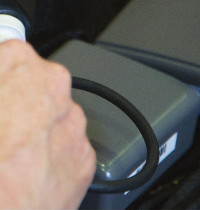
28 3.0 Handling HeartWare HVAD System Components 3.2 Making Connections Driveline Connection Only disconnect your driveline if instructed to do so by the controller during an alarm or by your clinician. Anytime your driveline is not connected to the controller, your pump is not running. To Disconnect the Driveline from the Controller: 1. Slide the driveline cover away from the controller so you can see the whole silver connector. 2. Place your fi ngers on the silver connector, over the ringed area. Figure Pull back on the ringed area to release the locking mechanism. Figure 18 NOTE: if you pull back on any other area of the driveline or connector it will not release the driveline from the controller. Figure 19 WARNINg! DO NOT disconnect the driveline from the controller or the pump will stop. If this happens, reconnect the driveline to the controller as soon as possible to restart the pump. WARNINg! ALWAYS keep a spare controller and fully charged spare batteries available at all times in case of an emergency. WARNINg! ALWAYS replace a controller if it has a blank display and/or no audible alarms. WARNINg! ALWAYS switch to the back-up controller if there is a [Controller Failed] alarm. CAUTION: DO NOT pull, kink or twist the driveline or the power cables. Special care should be taken not to twist the driveline while sitting, getting out of bed, adjusting controller or power sources, or when using the shower bag. CAUTION: ALWAYS keep extra driveline length tucked under clothing or secured with an abdominal binder or dressing. Do not let any portion of driveline hang freely where it might get caught on external items such as doorknobs or the corners of furniture. CAUTION: DO NOT pull, twist or kink the driveline or power cables, especially while sitting, getting out of bed, adjusting the controller or power sources, or when using the shower bag. 22


29 HVAD Patient Manual 3.2 Making Connections (continued) Driveline Connection (continued)3.2 To Connect the Driveline to the Controller: 1. Line up the red dots on the silver driveline connector and on the silver controller driveline port. Figure Push the driveline connector straight into the silver port. Note: Verify the pump is running to ensure proper connection. Figure Slide the driveline cover over the driveline connector. Figure 22 WARNING! DO NOT attach the alarm adapter to a controller that is connected to a running pump. The alarm adapter silences the [No Power] alarm and should only be attached to a controller that has failed or malfunctioned and is no longer connected to a pump. For information on exchanging your controller, see Section
 grasp the power cable near its connector. Leave the connector free to rotate. Figure 23 2.")

30 3.0 Handling HeartWare HVAD System Components 3.2 Making Connections (continued) Power Source Connections3 To Connect a Power Source: 1. To connect all power supplies (battery, AC adapter or DC adapter) grasp the power cable near its connector. Leave the connector free to rotate. Figure Line up the solid white arrow on the cable connector with the dot on the controller (Figure 24). Figure Gently push the cable into the controller. DO NOT twist the connector, but allow it to naturally lock in place. A good connection will result in an audible click. NOTE: When pushing the connector into the controller the white arrow will shift slightly into the correct locking position. Figure Confirm that the power cable is properly locked to the controller by gently pulling on the cable near the connector. Repeat steps above for second power source. WARNING! NEVER disconnect both power sources (batteries, AC adapter, DC adapter) at the same time since this will stop the pump and activate the [No Power] alarm. At least one power source must be connected at all times. CAUTION: ALWAYS confirm that the power cables are properly locked to the controller by gently pulling the cable near the connector. CAUTION: DO NOT force connectors together without proper alignment. Forcing together misaligned connectors may damage the connectors. CAUTION: ALWAYS keep all connectors free of liquid, dust and dirt, or the HeartWare HVAD System may not function as intended. 24

![Note: If another power source is not connected within 20 seconds, the [Power Disconnect] message will be displayed on the](/docs-images/86/93806081/images/31-1.jpg "Controller Display and an alarm will sound.")
31 HVAD Patient Manual 3.2 Making Connections (continued) Power Source Connections (continued) Disconnecting Power Sources: 1. Turn the connector counterclockwise until it stops. Figure Pull the connector straight out from the controller. Note: If another power source is not connected within 20 seconds, the [Power Disconnect] message will be displayed on the Controller Display and an alarm will sound. Figure 27 NOTE: The alarm will automatically clear when another power source is connected to the controller. 25
32 3.0 Handling HeartWare HVAD System Components 3.3 Changing Power Sources The controller will tell you when to change a battery through three indicators:1 1 Battery indicator will show 1 yellow light. 2 Alarm indicator will be solid yellow. 3 Display will read [Low Battery] [Replace Battery]. 1 2 Low Battery 1 Replace Battery 1 Changing from Two Batteries to a Battery and AC/DC Adapter 1. Plug the AC adapter into an electrical outlet or the DC adapter into a power port found in most cars. 2. Disconnect the battery with the least remaining charge. 3 Figure Connect AC or DC adapter. Proper connection is verified when the AC/DC Indicator on the controller turns green and the corresponding Battery Indicator turns off. If the AC/DC Indicator doesn t turn green, the controller is using battery power and the [Power Disconnect] alarm will sound. For additional information on making connections, see Section For additional information on alarms, see Section 4.2. warning! DO NOT plug the HeartWare Battery Charger AC adapter into an electrical outlet that is not properly grounded or you may receive a serious electrical shock. CAUTION: ALWAYS check to be sure the DC adapter works in your motor vehicle. The DC adapter is for use in motor vehicles only and may not fit all motor vehicles. CAUTION: Use only HeartWare-supplied power adapters with the HeartWare HVAD System. Changing from an AC/DC Adapter and Battery to Two Batteries Before switching from AC or DC power to battery power, make sure that a fully charged battery is available. Connect the fully charged battery after disconnecting the AC or DC adapter. 26

 will light up showing how much power is in each battery. See Table 3.")
33 HVAD Patient Manual 3.4 Using Battery Power It is important to understand how much charge a battery has before connecting to the controller. There are two ways to know if the battery is fully charged and ready for use: 1. The battery Test button 2. The battery charger For information on the battery charger, see Section 3.6. On the battery, press the Test button to light up the battery capacity display. Battery Capacity Display Test Button Figure 29 The battery capacity display (Figure 29) will light up showing how much power is in each battery. See Table 3. Table 3: Battery Capacity Battery Capacity Battery Capacity Display % 4 GREEN lights 50-74% 3 GREEN lights 25-49% 2 GREEN lights less than 25% 1 GREEN light CAUTION: ALWAYS recharge completely depleted batteries within 24 hours to avoid permanent battery damage. When one battery is depleted to less than 25% capacity, the controller will automatically switch to the other battery. When both batteries are depleted to less than 25%, both battery indicators will switch to 1 yellow. An intermittent beep will sound, the Alarm Indicator will be yellow, and a message will be displayed to replace Battery 1 (Figure 30). If the battery is NOT changed within 5 minutes, the alarm volume will escalate until the battery is exchanged with a fully charged battery. 27
34 3.0 Handling HeartWare HVAD System Components 3.4 Using Battery Power (continued) Battery Indicator 1 Controller Display Low Battery 1 Replace Battery 1 Alarm Indicator Active Battery Indicator Figure 30: Controller Display with a Low Battery Alarm When a depleted battery is not exchanged eventually, a high priority alarm will sound, the Alarm Indicator will be flashing RED and the message on the Controller Display will read [Critical Battery]. A charged battery or adapter (AC or DC) should be attached immediately to the power port with the critical battery indication. Never disconnect both power sources at one time. WARNING! NEVER disconnect both power sources (batteries, AC adapter, DC adapter) at the same time since this will stop the pump and activate the [No Power] alarm. At least one power source must be connected at all times. Table 4: Controller Battery Indicators If your controller shows: It means: You: 3000 RPM 5.0 L/min 4.8 Watts 3000 RPM 5.0 L/min 4.8 Watts Low Battery 1 Replace Battery 1 Low Battery 2 Replace Battery 2 You have 2 fully charged batteries connected to your controller. In this example, the battery connected to Power Source 1 is providing primary power. The battery connected to Power Source 1 has less than 25% capacity. In this example, the battery connected to Power Source 2 is fully charged and providing primary power. Both batteries connected to your controller have less than 25% capacity. In this example, the battery connected to Power Source 1 is providing primary power. The down arrow indicates there is another alarm. The battery connected to Power Source 2 has less than 25% capacity. In this example, an AC or DC adapter is connected to Power Source 1 and is providing primary power. Do not need to change either battery. Do not need to change either battery. Should attach a full battery or AC adapter to Power Source 1. Should connect a fully charged battery to Power Source 2. Critical Battery Replace Battery 2 The battery connected to Power Source 2 has limited time remaining. The battery connected to Power Source 1 has less than 25% capacity and is providing primary power. Should attach a full battery or AC or DC adapter to Power Source 2. Then, attach a full battery or AC or DC adapter to Power Source 1. Never disconnect both batteries at the same time. This will stop your pump. The controllers shown above are meant to be examples of the changes you might see during the day. 28
35 HVAD Patient Manual 3.5 Changing Battery Make sure there is a fully charged battery available to replace the depleted battery. Disconnect the depleted battery, replace it with the fully charged battery and confirm it is securely attached. For information on how to connect and disconnect power sources, see Section After a depleted battery is disconnected, the [Low Battery] alarm will resolve, as the controller will automatically switch to the second power source. If the second power source is not connected within 20 seconds, the [Power Disconnect] message will be displayed on the Controller Display and an alarm will sound. The alarm will automatically clear when the second power source is connected. When the battery is connected correctly, the Battery Indicator on the controller should light. WARNING! ALWAYS keep a spare controller and fully charged spare batteries available at all times in case of an emergency. 29


36 3.0 Handling HeartWare HVAD System Components 3.6 Battery Charger To Set up Your Battery Charger: 1. Insert the power cable into the back of the charger. Figure Plug the other end of the cable into a wall outlet. Figure Once the charger is connected to power, the green power light, located on the front bottom right side of the charger will be on. Figure 33 When a battery is connected, the battery charger checks the battery and begins charging. To connect a battery to the charger, follow the steps below: 1. Connect the battery to the power port located under each slot, the same way you connect a battery to the controller. Figure 34 For information on how to connect and disconnect power sources, see Section


37 HVAD Patient Manual 3.6 Battery Charger (continued) 2. Place the battery into the slot. For the best fi t, loop the cable gently to the side and place the battery with the cable-side down. Figure Repeat steps 1 and 2 for all batteries. The charger can hold up to 4 batteries at one time. Figure 36 Each battery charging slot has two lights that tell you the status of the battery. A green light next to "Ready" means the battery is fully charged. The light next to 'Status" may mean different things, depending upon the color. The table below describes the lights that appear next to "Status". Figure 37: Indicator Lights on Battery Charger 'Ready" Light "Status" Light 31
 Table 5: \"Status\" Light Description Battery Charger \"Status\" Light Yellow What it Means Battery being charged; NOT ready for use. Battery not charging.")

38 3.0 Handling HeartWare HVAD System Components 3.6 Battery Charger (continued) Table 5: "Status" Light Description Battery Charger "Status" Light Yellow What it Means Battery being charged; NOT ready for use. Battery not charging. Flashing Yellow Red Flashing Red Check battery connections. If connections are intact, switch to another battery slot. If problem persists, return battery to Clinician. Battery too cold or too hot; waiting to charge. Defective battery. Do NOT use. Mark battery and return to Clinician. CAUTION: NEVER use other battery chargers to charge HeartWare Batteries. Other battery chargers may damage the batteries. CAUTION: ALWAYS wait until the "Ready" light turns on to disconnect the battery from the battery charger. If this is not followed over consecutive charging cycles, the Battery Capacity Display will not function properly and may convey misleading battery capacity. Disconnecting Batteries from the Battery Charger: The battery disconnects from the battery charger the same way it disconnects from the controller. 1. Disconnect the battery by turning the connector counterclockwise until it stops. 2. Pull the connector straight out from the battery charger. Figure 38 Figure 39 For additional information on disconnecting power sources, see Section


39 HVAD Patient Manual 3.7 Setting Up Your HeartWare HVAD System Carrying Cases To Set Up and Use Your HeartWare Shoulder Pack: 1. Place the shoulder pack on a table or other flat surface with the clear window facing you. Note: For added support, attach the waist belt to the shoulder pack using the belt loops on the back of the pack before loading any equipment into it. If necessary, use the belt extender to make the belt longer. Figure Open top flap and unzip the zippers to access the equipment pockets. Figure Open the magnetic flaps. Figure Open the large flap to access the equipment pockets. Pocket for Patient ID Card You should receive a patient ID Card from your clinician, which can be placed in the clear pocket. Figure Open the snap-on buttons snaps on the controller pocket. Figure 44 Steps continued on next page 33

: 6. Place the controller in the controller pocket. 7.")


40 3.0 Handling HeartWare HVAD System Components 3.7 Setting Up Your HeartWare HVAD System Carrying Cases (continued) To Set Up and Use Your HeartWare Shoulder Pack (continued): 6. Place the controller in the controller pocket. 7. Fasten the snap-on buttons to secure the controller. Figure 45 Figure Insert the batteries into the two battery pockets. The extra battery cable length can be tucked into the pocket with the battery. Make sure the battery cables are not twisted or kinked. Figure Close the large flap. Figure Zip up both zippers. Figure Close both side magnetic flaps. Figure 50 Steps continued on next page 34


41 HVAD Patient Manual 3.7 Setting Up Your HeartWare HVAD System Carrying Cases (continued) 12. Check that the driveline is between the top of the zipper and the closed side flap. 13. Fold the top cover closed. Figure 51 Figure Place the shoulder pack strap over your head and across your shoulder so it is hanging at your side (near the exit site). Adjust the strap as needed so the pack does not pull on the driveline. If you used the waist belt, tighten it as needed. Figure 53 CAUTION: DO NOT pull, twist or kink the driveline or power cables, especially while sitting, getting out of bed, adjusting the controller or power sources, or when using the shower bag. CAUTION: DO NOT pull, kink or twist the driveline or the power cables. Special care should be taken not to twist the driveline while sitting, getting out of bed, adjusting controller or power sources, or when using the shower bag. CAUTION: The HeartWare Waist Pack and the HeartWare Shoulder Pack contain magnetic closures. Patients with an internal cardiac defibrillator (ICD) or pacemaker should keep the pack away from their chest, including when sleeping. Per pacemaker and ICD manufacturer guidelines, magnets should be kept at least 6 inches (15 centimeters) away from the pacemaker or ICD (please refer to manufacturer guidelines for additional information). 35

42 3.0 Handling HeartWare HVAD System Components 3.7 Setting Up Your HeartWare HVAD System Carrying Cases (continued) To Set Up and Use Your HeartWare Waist Pack: 1. Place the waist pack on a table or other flat surface with the clear window facing you. Attach the support strap as shown. Open the cover and undo the snaps of the controller pocket. Figure Place the controller as shown. Figure Fasten the snaps and fold the cover closed. Figure To load the batteries: Disconnect one battery from the controller. Open the battery pocket and feed the battery cable through the hole and then place the battery in the pocket. Re-connect the battery to the controller and fold the battery pocket cover closed. Figure 57 For additional information on connecting power sources, see Section Steps continued on next page 36

43 HVAD Patient Manual 3.7 Setting Up Your HeartWare HVAD System Carrying Cases (continued) 5. Secure the cable in the cable sleeve by opening the flap, placing the cable inside, and closing the flap. Figure Repeat steps 4 and 5 for the other battery. Figure Lift the support strap over your head to hold the HeartWare Waist Pack up, then buckle the belt around your waist and adjust it to fit. If necessary, use the belt extender to make the belt bigger. Check the driveline and battery cables to make sure that they are not twisted or kinked. Adjust the pack as necessary to remove kinks in the driveline or cables. Figure Adjust the belt so that the Controller Display is visible at all times. When the HeartWare Waist Pack is comfortably fastened around the waist, the support strap can be removed. NOTE: Always use the support strap when putting on or taking off the waist pack. Figure 61 caution: DO NOT pull, twist or kink the driveline or power cables, especially while sitting, getting out of bed, adjusting the controller or power sources, or when using the shower bag. caution: DO NOT pull, kink or twist the driveline or the power cables. Special care should be taken not to twist the driveline while sitting, getting out of bed, adjusting controller or power sources, or when using the shower bag. caution: The HeartWare Waist Pack and the HeartWare Shoulder Pack contain magnetic closures. Patients with an internal cardiac defibrillator (ICD) or pacemaker should keep the pack away from their chest, including when sleeping. Per pacemaker and ICD manufacturer guidelines, magnets should be kept at least 6 inches (15 centimeters) away from the pacemaker or ICD (please refer to manufacturer guidelines for additional information). 37
 To Set Up and Use Your")
 Lay the bag on a flat surface.")
 Open the clips on the Controller compartment. b) Open the side flaps. 3.")
44 3.0 Handling HeartWare HVAD System Components 3.7 Setting Up Your HeartWare HVAD System Carrying Cases (continued) To Set Up and Use Your HeartWare Convertible Patient Pack: To load the Controller and batteries into the HeartWare Patient Pack: 1. a) Lay the bag on a flat surface. b) Open the top flap with the clear window facing you. Figure a) Open the clips on the Controller compartment. b) Open the side flaps. 3. Place the Controller in the compartment. - The display screen should be facing you. Figure 63 Figure 64 Steps continued on next page 38
 Close the side flaps. Figure 65 5. a) Place each battery pack into the individual battery compartments behind the controller.")
 Close the top flap of the Patient Pack and ensure contents are secure (Figure 67a).")

45 HVAD Patient Manual 3.7 Setting Up Your HeartWare HVAD System Carrying Cases (continued) 4. a) Fasten the clips on the Controller compartment to secure the Controller. b) Close the side flaps. Figure a) Place each battery pack into the individual battery compartments behind the controller. b) Tuck the excess battery cable length inside the battery compartment. Figure a) Close the top flap of the Patient Pack and ensure contents are secure (Figure 67a). b) The Controller Display screen should be visible through the clear window (Figure 67b). Figure 67a Figure 67b caution: DO NOT pull, twist or kink the driveline or power cables, especially while sitting, getting out of bed, adjusting the controller or power sources, or when using the shower bag. caution: DO NOT pull, kink or twist the driveline or the power cables. Special care should be taken not to twist the driveline while sitting, getting out of bed, adjusting controller or power sources, or when using the shower bag. 39
46 3.0 Handling HeartWare HVAD System Components 3.8 How Long HeartWare HVAD System Equipment Should Last The HeartWare HVAD System components were designed and tested to function for the following periods: HVAD Pump for two years. The controller for two years. Each fully charged battery provides approximately 4 to 7 hours of use for normal activities such as reading or watching TV. The battery may last for less time as your activity level increases. However, if any battery provides less than 2 hours of support, it should be replaced. Similar to the battery in a cell phone (or mobile phone), the HeartWare Batteries lose charge over time. If a fully charged battery lasts less than 2 hours, take it out of service and replace it with a new one. During your clinic visit, your health care provider might inspect your battery and download information from your controller to determine the number of times your battery has been charged and discharged. The batteries are expected to have a useful operating life of 500 charge and discharge cycles. Batteries that reach the end of their useful life should be taken out of service and replaced. If you rotate the use of your batteries, you should get 1 year of battery service. 40
47 HeartWare HVAD System 4.0 Emergencies and Alarms 4.1 Handling an Emergency Overview of Alarms [No Power] Alarm High Alarms Medium Alarms Low Alarms Multiple Alarms How to Silence (Mute) Alarms Changing Controller to Back-Up Controller
48 4.0 Emergencies and Alarms 4.1 Handling an Emergency Emergencies may occur with your HeartWare HVAD System, with or without an alarm. A back-up controller and charged batteries must be available at all times. The controller should be exchanged if it fails. For information on how to change the controller, see Section 4.9. Call your clinician immediately if you notice a sudden change in how your pump works, feels or sounds (even if there is no alarm). Emergencies may also be related to how you feel. If there is an emergency such as an urgent or life-threatening problem, call your local emergency medical services and then your clinician, if possible. Contact your clinician for any of the following conditions: Numbness, tingling or weakness in any limb Blurred vision or speech problems Shortness of breath or dizziness Any pain, including chest pain, unrelieved headache Fever (take your temperature daily) Any redness, swelling or drainage around the driveline exit site Unusual bleeding or bruising Unusually dark urine Any condition where you feel unwell High and medium controller alarms Call Emergency Medical Services (EMS) for any of the following conditions: Seizure or convulsion Loss of consciousness Awake but unresponsive Sudden fall or collapse Inability to talk or move body parts Heart stops VAD stops In case of emergency, it is safe for you to be transported by ground or air to your implanting hospital or nearest hospital. 42
49 HVAD Patient Manual 4.2 Overview of Alarms Alarms tell you about the pump, controller, connections, and power sources (batteries, AC adapter, DC adapter). Alarm conditions are classified as high, medium or low. Each of these alarms has a 1) unique sound, 2) visual display and 3) a message. See table below. Table 6: Alarms High Medium Low Flashing Red Triangle Flashing Yellow Triangle Solid Yellow Triangle Controller Display Controller Audio Loudest intermittent beep Cannot be silenced by the Mute button Intermittent beep that becomes louder in 1 and 5 min Intermittent beep that becomes louder in 5 and 10 min Controller Silencing Cannot be silenced by the Mute button The alarm will clear once the problem is resolved May be silenced for 5 min or 1 hour Controller and Electrical Faults may be permanently silenced May be silenced for 5 min When an alarm occurs, two lines of text appear in the Controller Display. The first line tells you what the alarm is and the second line tells you what to do. See example below: 1st line tells you what the alarm is 2nd line tells you what do to Low Battery 1 Replace Battery 1 Figure 68 When an alarm is resolved, there is no longer an alarm sound or a light displayed in the Alarm Indicator ( ). WARNING! ALWAYS keep a spare controller and fully charged spare batteries available at all times in case of an emergency. WARNING! ALWAYS investigate, and if possible, correct the cause of any alarm. Silencing an alarm does not resolve the alarm condition. 43
50 4.0 Emergencies and Alarms 4.3 [No Power] Alarm If both power supplies (batteries, AC adapter, DC adapter) are removed, there will be NO message on the Controller Display. A loud continuous alarm will sound but the Alarm Indicator WILL NOT light. Your pump has stopped. You need to connect power immediately. If this does not resolve the alarm, immediately replace the controller with the back-up controller. WARNING! NEVER disconnect both power sources (batteries, AC adapter, DC adapter) at the same time since this will stop the pump and activate the [No Power] alarm. At least one power source must be connected at all times. 4.4 High Alarms A high alarm demands immediate action for VAD (pump) stoppage, controller failure or limited power to run the pump. After the condition is resolved, the audible tone will stop, the alarm message will automatically clear from the controller and VAD parameters will be displayed on screen. The table below describes high alarms and possible meaning. Table 7: High Alarms Alarm (Line 1 on controller) Action (Line 2 on controller)^ Meaning Alarm Indicator Alarm Sound [VAD Stopped] [Connect Driveline] Driveline disconnected or connector malfunction/ broken [VAD Stopped] [Change Controller] Controller failure [Controller Failed] [Change Controller] [Critical Battery] [Replace Battery 1] Controller failure Limited time remaining on battery connected to Power Source 1 Flashing RED Loud Unable to mute alarm [Critical Battery] [Replace Battery 2] Limited time remaining on battery connected to Power Source 2 ^ Immediate action required, and then call your clinician. WARNING! ALWAYS switch to the back-up controller if there is a [Controller Failed] alarm. 44
51 HVAD Patient Manual 4.5 Medium Alarms A Medium Priority Alarm may resolve on its own/without intervention, but follow the instructions on the screen and call your clinician immediately to receive instructions. Once resolved, the alarm message may remain on the Controller Display. Press the Scroll button to clear the alarm message from the Controller Display and return to the screen with VAD parameters. A new alarm will also clear a resolved medium alarm from the Controller Display. The table below describes medium alarms and possible meaning. Table 8: Medium Alarms Alarm (Line 1 on controller) Action (Line 2 on controller) Meaning Alarm Indicator Alarm Sound [High Watts] [Call]* [Electrical Fault] [Call]* [Low Flow] [Call]* [Suction] [Call]* [Controller Fault]^ [Call]* [Controller Fault]^ [Call ALARMS OFF]* A change in the status of your VAD is detected Possible controller malfunction Flashing Yellow Gradual increase in volume over the first minute if alarm not muted. Alarm gets louder after 5 minutes if alarm not muted. Able to mute alarm for 5 minutes by pressing Alarm Mute button. ^ Controller Fault indicates a possible controller malfunction. Call your clinician for appropriate action. The controller may need to be replaced with the back-up controller. * Call your clinician immediately. CAUTION: ALWAYS call your clinician for appropriate action if there is a [Controller Fault] alarm. The controller may need to be replaced with the back-up controller. Quick reference guide for controller alarms is available from your clinician. 45

52 4.0 Emergencies and Alarms 4.6 Low Alarms A low alarm is resolved by following the instructions on the screen. Once resolved, the audible tone will stop, the alarm message will automatically clear from the controller and VAD parameters will be displayed on screen. The table below describes low alarms and possible meaning. Table 9: Low Alarms Alarm (Line 1 on controller) Action (Line 2 on controller) Meaning Alarm Indicator Alarm Sound [Low Battery 1] [Replace Battery 1] [Low Battery 2] [Replace Battery 2] [Power Disconnect] [Reconnect Power 1] [Power Disconnect] [Reconnect Power 2] Battery 1 is low Battery 2 is low Power Source 1 disconnected or defective Power Source 2 disconnected or defective Yellow Alarm gets louder after 5 minutes and even louder after 10 minutes, if alarm not muted. Able to mute alarm for 5 minutes by pressing Alarm Mute Button. NOTE: [Low Battery 2] [Replace Battery 2] will appear on the Controller Display screen as the second alarm until Battery 1 is replaced with a new power source. WARNING! ALWAYS respond to low battery alarms. Silencing an alarm does not resolve the alarm condition and will eventually deplete the batteries. 4.7 Multiple Alarms You may have more than one alarm condition at the same time. As mentioned previously, when an alarm occurs, two lines of words appear on the Controller Display. The first line tells you what the alarm is, and the second line tells you what to do. An arrow ( ) is displayed on the right side of the alarm if there is more than one alarm (Figure 69). For multiple alarms, the Alarm Indicator ( ) and alarm sound will display the most severe alarm. Follow the directions on the display for the most severe alarm, first. Then scroll to the additional alarms. Figure 69: Controller with Multiple Alarms (Note Arrow in Controller Display) 46
53 HVAD Patient Manual 4.7 Multiple Alarms (continued) WARNING! NEVER disconnect both power sources (batteries, AC adapter, DC adapter) at the same time since this will stop the pump and activate the [No Power] alarm. At least one power source must be connected at all times. Alarm Indicator and Alarm Sound for Multiple Alarms Table 10: Multiple Alarms Multiple Alarm Condition Alarm Indicator Alarm Sound 2 or More High Alarms Flashing RED High and Medium Alarms High and Low Alarms Flashing RED Flashing RED Loud, continuous, unable to mute 2 or More Medium Alarms Flashing Yellow Medium and Low Alarms Flashing Yellow 2 or More Low Alarms Yellow Gradual increase in volume if alarm NOT muted Use the Scroll button to see all alarm conditions. Press the Scroll button each time you want to advance to the next alarm or to the VAD parameters (L/min, RPM and Watts). If the Scroll button is not touched for 1 minute, the controller automatically displays the most severe alarm on the Controller Display. Also, if a new alarm occurs, the Controller Display will show you the new alarm. Remember, if an arrow is displayed on the right side of the alarm message; use the Scroll button to see all alarms. 4.8 How to Silence (Mute) Alarms High alarms CANNOT be silenced. However, medium and low alarms can be silenced for 5 minutes by pressing the Alarm Mute button. The alarm will sound again if a new alarm condition occurs or five minutes has passed. The low and medium alarm sound will increase to the next highest alarm volume level if the alarm condition is not resolved or is not muted within 5 minutes. WARNING! ALWAYS investigate, and if possible, correct the cause of any alarm. Silencing an alarm does not resolve the alarm condition. 47


54 4.0 Emergencies and Alarms 4.9 Changing Controller to Back-Up Controller You should only change your controller when instructed to do so by your clinician, or if there is a blank display screen when attached to a functioning power supply or if the Controller Display shows one of the following: If possible, a caregiver should be nearby when doing a controller change. Steps to Change the Controller: 1. Sit or lie down and place your back-up controller within easy reach. Your backup controller will become your new controller. Figure Connect one POWER source to the new controller. NOTE: The new controller may alarm after 10 seconds with a [VAD Stopped, Connect Driveline] high alarm. This is expected behavior. Figure 71 Steps continued on next page 48


55 HVAD Patient Manual 4.9 Changing Controller to Back-Up Controller (continued) Steps to Change the Controller (continued): 3. Disconnect the driveline from the original controller and connect the driveline to the new controller. This should restart your PUMP. Verify that the pump is working. The RPM, L/min and Watts numbers should show on the Controller Display. If your pump does not restart, re-check driveline and power source connections, if it still doesn t start call for medical assistance immediately. Figure 72: Disconnect Figure 73: Connect If you have only connected 1 power source to the new controller, you will also have a [Power Disconnect, Reconnect Power] alarm. Steps continued on next page 49


56 4.0 Emergencies and Alarms 4.9 Changing Controller to Back-Up Controller (continued) Steps to Change the Controller (continued): 4. PREVENT the [No Power] alarm from sounding on the original controller. This needs to be done before removing all power. There are 2 options, see below: If a red alarm adapter is available: Insert it into the connector with the dust cap (data port) on the original controller. You can now remove all power from the original controller and no alarm should sound. Figure 74 If no red alarm adapter is available: Press and hold the "Alarm Mute" and "Scroll" buttons on the original controller until a beep is heard, or for at least 5 seconds. Release the "Alarm Mute" and "Scroll" buttons. You can now remove all power from the original controller and no alarm should sound. Figure 75 If you removed power before silencing the [No Power] alarm, reconnect a power source and follow the steps above to silence it. NOTE: If the [No Power] alarm is not disabled prior to removing both power sources, the controller alarm may sound for up to 2 hours. 50


57 HVAD Patient Manual 4.9 Changing Controller to Back-Up Controller (continued) Steps to Change the Controller (continued): 5. Connect a second POWER source to the new controller. Figure Be sure the driveline cover is over the silver driveline connector and the data port is covered by the dust cap. If the red alarm adapter is connected to the controller that is now running the pump, remove it and close the cap on the data port. Figure Call your clinician to obtain a new back-up controller. 51
58 4.0 Emergencies and Alarms 4.9 Changing Controller to Back-Up Controller (continued) When doing a controller exchange, the priority is to restart your pump quickly. It may be helpful to remember the 4 P s: 1. POWER... Connect a power source to your back-up controller. 2. PUMP... Restart your pump by connecting your driveline to the new controller. 3. PREVENT... Prevent the [No Power] alarm on the original controller with the red alarm adapter or by pressing the Scroll and Mute buttons at the same time. 4. POWER... Connect a second power source to the new controller. WARNING! DO NOT attach the alarm adapter to a controller that is connected to a running pump. The alarm adapter silences the [No Power] alarm and should only be attached to a controller that has failed or malfunctioned and is no longer connected to a pump. WARNING! ALWAYS replace a controller if it has a blank display and/or no audible alarms. WARNING! ALWAYS switch to the back-up controller if there is a [Controller Failed] alarm. CAUTION: ALWAYS keep extra driveline length tucked under clothing or secured with an abdominal binder or dressing. Do not let any portion of driveline hang freely where it might get caught on external items such as doorknobs or the corners of furniture. CAUTION: DO NOT force connectors together without proper alignment. Forcing together misaligned connectors may damage the connectors. CAUTION: ALWAYS confirm that the power cables are properly locked to the controller by gently pulling the cable near the connector. CAUTION: DO NOT pull, twist or kink the driveline or power cables, especially while sitting, getting out of bed, adjusting the controller or power sources, or when using the shower bag. For information on making good connections, see Section 3.2. For more information on alarms, See Section 4.2. Changing the Controller Guide is available from your clinician. 52
59 HeartWare HVAD System 5.0 Preparing for Discharge 5.1 Equipment Needed to Go Home Discharge Instructions Patient and Caregiver Training
60 5.0 Preparing for Discharge Before going home, your clinician will make sure you understand how to handle and care for your HeartWare HVAD System, care for your exit site and know what to do in an emergency. They will also schedule follow up appointments for you. 5.1 Equipment Needed to Go Home At the time of discharge from the hospital, be certain that all of the following equipment and accessories are available and have been checked for proper function. 1 Patient Manual 2 Controllers with AC adapters (1 set is for back-up) and alarm adapters 1 Driveline cover 1 DC adapter At least 4 batteries 1 Battery charger 1 or more carrying cases (Shoulder Pack, Waist Pack or Patient Pack) 1 Shower bag 5.2 Discharge Instructions At the time of discharge from the hospital, be certain to follow the instructions below. Daily Care 1. Change your VAD exit site dressing once a day following the sterile technique taught to you while in the hospital. During dressing changes look for signs of infection, such as redness, swelling, drainage or pain. Call your clinician if you notice any of these symptoms. 2. Call your clinician if your VAD flow falls to less than L/min, the power goes above Watts or the speed changes by more than 100 RPM. 3. Call your clinician if your temperature is above degrees. 4. Check your weight each morning and record it on your flow sheet. Call your clinician if you gain more than pounds in one week. Continued on next page 54
61 HVAD Patient Manual 5.2 Discharge Instructions (continued) 5. Take and record your blood pressure as your clinician team instructed. Reducing blood pressure has been shown to reduce the risk of stroke. Your clinician will teach you how to check your blood pressure. Call your clinician if it is higher than. 6. Call your clinician if you notice any swelling in your ankles or changes in your girth. This may be a sign of water retention. 7. Notify your clinician if there is a change in how the VAD sounds or feels. 8. Record your VAD speed (RPM), power (Watts) and flow (L/min) once a day. Care of Equipment 1. Do NOT twist or kink your driveline. 2. Keep all your VAD equipment in a dry, room temperature (around +72 F) environment. Store all extra equipment in your house. Be sure the equipment is stable if stored in closets or shelves. Dropping VAD components may lead to damage. 3. When not in use keep batteries plugged into the charger the charger should always be plugged into an AC outlet. 4. If you have any questions about operating, cleaning or storing your VAD equipment, ask your clinician. 5. Do not try to repair or modify any of your VAD equipment. Pain By the time you are ready to go home, you should not be having much pain. You may be sent home with pain medication which should be taken as prescribed. If you experience an increase in pain or pain where you never had pain before, call your clinician. Diet 1. Follow the diet suggested by the dietitian. 2. If you have diabetes, be aware that your diabetes medications may need to be adjusted after VAD implantation. Talk to your clinician about any changes that are needed. 55
62 5.0 Preparing for Discharge 5.2 Discharge Instructions (continued) Tobacco Products If you smoke - you must quit smoking. NOTE: Avoid second-hand smoke as it has negative effects on your blood vessels. Alcohol Alcohol can interfere or interact with certain medications and leads to dehydration. Alcohol can impair your ability to understand and react to system alarms. Weather 1. Avoid activity in very hot or very cold temperatures. 2. If you go outdoors during very hot or humid weather, be sure to drink plenty of water or non-alcoholic beverages. Limitations 1. Do NOT take baths, get in a hot tub, or go swimming while implanted with your VAD. After the VAD implant, while still in the hospital, you will receive instructions on the method and equipment needed for daily hygiene. 2. Do NOT drive a car or operate heavy machinery unless your clinician gives you permission. 3. Do NOT play contact sports or engage in any activity that may lead to stitches, trauma or broken bones while implanted with the VAD. Miscellaneous 1. You are responsible for making sure that your surroundings continue to be safe. If you have any questions or concerns about your home environment, call your clinician. 2. Be familiar with the warnings and precautions associated with having a VAD and for safe HeartWare HVAD System operation. 56
63 HVAD Patient Manual 5.3 Patient and Caregiver Training 1. Match the item with the correct function: Fill in your answers below: AC Adapter Alarm Indicator Alarm Mute Button a This icon is located at the front of the controller and lights up when one or more alarms occur. b This button silences the low and medium audible alarms. c This is an adapter/cable that transfers power from an electric outlet to run the controller. 2. Match the definition to the picture: Fill in your answers below: Test Button on Battery Driveline Exit Site Battery Charger a b c 3. Match the controller label names: Fill in your answers below: AC/DC Indicator Controller Display a b c d f g Alarm Indicator Alarm Mute Button e Battery Indicator 1 Battery Indicator 2 Scroll Button Continued on next page 57
64 5.0 Preparing for Discharge 5.3 Patient and Caregiver Training (continued) 4. Match the cable connector names on the controller: Fill in your answers below: Monitor Cable / Alarm Adapter Power Source c a b d Power Source Driveline 5. Circle True or False for the following: 1. A flashing red alarm requires immediate attention. True False 2. It is ok to have moisture, cracks, tears or punctures in your driveline. True False 3. It is safe to take a tub bath or swim. True False 4. This button is used to see all active alarms and pump VAD parameters on the Controller Display. True False 5. Pushing the ALARM MUTE BUTTON to silence an alarm does not resolve the alarm condition. True False 6. A controller with a blank display and no audible alarm should be replaced. True False 7. When an alarm occurs, Line 1 of the Controller Display tells you which alarm is occurring, Line 2 tells you what to do. True False 8. A green indicator light on the AC or DC adapter will indicate proper connection to an electrical outlet or a car power port. True False 9. When there is a [Controller Failed] alarm, you should switch to the back-up controller. True False Continued on next page 58
65 HVAD Patient Manual 5.3 Patient and Caregiver Training (continued) 6. List 2 items you should have with you when you leave your house: 7. List 2 signs or symptoms of a driveline exit site infection: 8. How long does one battery usually provide power? 9. Why do you take blood thinner medicine? 10. When looking at the controller, how much power is remaining in a battery if there are: 4 green lights % 2 green lights % 3 green lights % 1 yellow light % 11. Check the activities that will cause the HeartWare HVAD System to stop: Disconnecting the AC adapter while only one fully charged battery remains connected to the controller. Disconnecting both batteries at the same time. Disconnecting the driveline from the controller. Unplugging the DC adapter without a back-up battery connected to the controller. Continued on next page 59
66 5.0 Preparing for Discharge 5.3 Patient and Caregiver Training (continued) 12. Two power sources should be connected to the controller at all times. What are the 3 different power options? Battery and Battery and Battery and 13. Check the activities that are not allowed while on the HVAD Pump: Chest X-ray MRI Scan CT Scan Cardiac Catheterization Swimming Walking 14. On the battery charger there are several "Status" light indicators. Check which "Status" light you will see if the battery is charging and is not ready for use. Blue Flashing Red Yellow No lights 15. When an alarm occurs, check the 3 indicators that you should look for to determine the severity of the alarm. A unique sound Visual display (flashing RED, flashing Yellow, or Yellow) Vibrating A message 60

67 HVAD Patient Manual 5.3 Patient and Caregiver Training (continued) 16. Circle True or False for the following: 1. The RED ALARM ADAPTER silences the [No Power] alarm and should only be attached to a controller that is not connected to a pump. True False 2. Pressing clears a message on the Controller Display when a medium alarm has resolved and there is no alarm sound or light displayed in the Alarm Indicator. True False 3. These are all things that should be reported right away to your clinician: a) You ve dropped and/or damaged any of your equipment b) A battery(s) that lasts less than 2 hours after being fully charged c) You have an active medium alarm that states [Controller Fault, Call] on the display screen. True False 17. The CONTROLLER DISPLAY gives pump information such as: Match the definition of the items: Fill in your answers below: Power Blood Flow Speed a b c RPM Watt L/min 18. You suddenly get a high priority alarm [VAD Stopped, Connect Driveline] on your Controller Display. What is the first thing you would do? 61
68 5.0 Preparing for Discharge 5.3 Patient and Caregiver Training (continued) 19. To minimize the risk of interference (electrostatic discharge) to your controller due to static electricity, which of the following should you avoid? Check all that apply. Putting your controller in a silk bag Using dryer sheets when doing laundry Using a humidifier in your home Touching the TV screen while it is on Operating on one battery while going to the restroom in the middle of the night Ensuring that the driveline cover is firmly positioned against the controller 20. When preparing to go to bed at night, you should do which of the following? Connect an AC adapter, then a fully charged battery Connect an AC adapter and leave battery connected that has less than full charge Connect 2 fully charged batteries, one at a time 21. Your controller displays the following information; what is the correct response? Do nothing, this is normal activity Low Battery 1 Replace Battery 1 Change Battery 1 and Battery 2 Change Battery 1 Change Controller 22. Your controller displays the following information; what is the correct response? Do nothing, this is normal activity Critical Battery Replace Battery 2 Change Battery 1, then Battery 2 Replace Battery 2 with the AC adapter, then replace Battery 1 with a new Battery Change Battery 1 Change Controller 62
69 HeartWare HVAD System 6.0 Living with the HeartWare HVAD System 6.1 Medications Understanding and Preventing Electrostatic Discharge (ESD) Exit Site Care Washing and Showering Loading the Shower Bag Traveling and Transport
70 6.0 Living with the HeartWare HVAD System People who receive a VAD may notice an improvement in symptoms beginning in the hospital and will continue to get stronger in the weeks following surgery. However, adjusting to living with a VAD may take time. This manual provides some information about living with your HeartWare HVAD System. Call your clinician if you have any questions about activities not included in this manual. WARNING! DO NOT become pregnant while you have the HeartWare HVAD System. If you are a woman of childbearing age, use birth control if you are sexually active. Blood thinners (which most VAD patients receive) have been associated with birth defects. If you do become pregnant, tell your clinician immediately. WARNING! ALWAYS check the Controller Display for any information regarding an alarm when using loud machinery or in the vicinity of loud noises since under these conditions, the controller and battery alarms may not be audible. WARNING! DO NOT have a magnetic resonance imaging (MRI) procedure while implanted with the HeartWare HVAD System. Doing so could harm you or cause the pump to stop. WARNING! Keep mobile phones at least 20 inches (50 centimeters) away from the controller, as mobile phones may interfere with controller operation. WARNING! DO NOT undergo procedures requiring high power electrical treatment while the pump is implanted. High power electrical treatments are typically prescribed for joint conditions such as rheumatoid arthritis and osteoarthritis and use high frequency electrical current to produce deep heat inside the body intended to decrease inflammation and pain. Consult your clinician before having any deep tissue heating procedures. WARNING! AVOID exposure to therapeutic levels of ultrasound energy. Consult your clinician before having lithotripsy procedures to treat kidney stones or any treatments involving high intensity ultrasound. The implanted device may inadvertently concentrate the ultrasound field and cause harm. WARNING! AVOID therapeutic ionizing radiation. Consult your clinician before having any nuclear medicine procedures or radiation therapy for cancer. Radiation may damage the device and may not be immediately detectable. CAUTION: DO NOT play contact sports. You may start bleeding or could damage your equipment. CAUTION: Do not expose the driveline to direct or indirect sunlight. Keep the driveline completely covered when in the sun. DO NOT use tanning lights or black lights. The light from these sources may damage the outer covering of the driveline. 64
71 HVAD Patient Manual 6.1 Medications Talk with your clinician about your medications. Get an explanation of the purpose of each medication that your doctor prescribes for you. Write down the medication and how often you need to take it and ask your doctor to check the list to make sure it is correct. Talk with your clinician about what you should do if you accidentally forget to take your medicine. Discuss what to do for each medicine because it may be different for each one. You may also want to make a list of medications that you should not take. Some non-prescription medications and natural supplements may react with your prescribed medications. You are probably taking medication (anticoagulation) to thin your blood and reduce the risk of clot formation in your blood or pump. It is very important that you take this medication as prescribed and that you have your blood checked frequently to be sure that you are receiving a dose that is not too high (blood too thin) or too low (blood too thick). You may notice bleeding as a result of your medication. If you are unsure whether the bleeding represents a problem, it is best to call your clinician. NOTE: You should always remain on your anticoagulation dose schedule as written or as told to you by your clinician. 6.2 Understanding and Preventing Electrostatic Discharge (ESD) What is Electrostatic Discharge? Electrostatic discharge (ESD) is the sudden transfer of electricity from one object to another. It is most noticeable in dry environments and near certain materials such as silk and carpeting. A mild shock to your skin will not affect your controller. However, ESD to the controller or its connectors may cause your controller to function improperly. 65
72 6.0 Living with the HeartWare HVAD System 6.2 Understanding and Preventing Electrostatic Discharge (ESD) (continued) WARNING! Avoid devices and conditions that may induce strong static discharges (e.g., television or computer monitor screens) as electrostatic discharges can damage the electrical parts of the system and cause the VAD to perform improperly or stop. WARNING! The HeartWare HVAD System components should not be used adjacent to or stacked with equipment other than specified in the Patient Manual. If adjacent to or stacked use is necessary, the HeartWare HVAD System and other equipment should be observed to verify normal operation. WARNING! Always have a back-up controller handy and, whenever possible, a caregiver nearby when changing power sources or controllers. Be watchful for unusual changes in power or flow alarms for a period of time following equipment changes. ESD damage to the controller can cause: 1. A [Controller Failed] alarm 2. A High audible alarm without accompanying alarm text on the Controller Display If either of those alarms occur: Switch to your back-up controller and contact your clinician 3. A [Controller Fault] alarm If that alarm occurs, contact your clinician for instructions For additional information about alarms, see Section 4.2. What you can do to reduce the chance of ESD damage to the controller: 1. Make good connections when changing power sources Do not touch the controller connector ports, or let foreign objects or materials come near a disconnected controller power port. Have new battery within reach before disconnecting power source and when possible, have a caregiver nearby in case an alarm occurs Use 2 power sources. Only leave power source ports on controller open for the time it takes to change the power sources. Refer to making connections for additional information, Section Be careful near materials and electronic devices prone to static electricity, such as: carpeted floors, silk clothing, TV screens, microwaves when in operation, and laptop or computer screens. Avoid changing power sources in these areas Avoid vacuuming and removing clothes from the dryer Use anti-static dryer sheets and fabric softener Consider humidifier in your house 66
73 HVAD Patient Manual 6.3 Exit Site Care Proper care of your skin around the driveline exit site is very important to prevent infection in this area. Prior to leaving the hospital, your clinician will explain and demonstrate proper care of the exit site. One of the most important measures you can take to prevent exit site infections is to protect the driveline from excessive movement. Take care not to pull on the driveline or get it caught on objects where the result may be sudden pulling or yanking. The dressing around your exit site should be changed according to your clinician s instructions. Always thoroughly wash your hands with soap and water prior to any dressing change. Always use sterile technique with every dressing change. General guidelines include: 1. Obtain all necessary materials 2. Wash your hands thoroughly 3. Remove dressing 4. Observe exit site for redness, swelling or drainage 5. Open new dressings 6. Use sterile gloves 7. Cleanse the exit site with saline or other agent (start close to the driveline and then move away) 8. Apply sterile dressings 9. Tuck any excess driveline length under an abdominal binder or dressing or keep it secured close to the body underneath clothing CAUTION: DO NOT pull, kink or twist the driveline or the power cables. Special care should be taken not to twist the driveline while sitting, getting out of bed, adjusting controller or power sources, or when using the shower bag. CAUTION: ALWAYS keep extra driveline length tucked under clothing or secured with an abdominal binder or dressing. Do not let any portion of driveline hang freely where it might get caught on external items such as doorknobs or the corners of furniture. CAUTION: ALWAYS notify your clinician promptly if there is drainage, swelling or reddened skin around the driveline exit site. These may indicate an infection. CAUTION: DO NOT use prophylactic topical antibiotic ointments such as silver sulfadiazine, povidone iodine (betadine), or polymyxin-neomycin-bacitracin ointment around your exit site. These ointments can injure the tissue next to your driveline. CAUTION: ALWAYS examine the driveline for evidence of tears, punctures or breakdown of any of the material during exit site dressing changes. Report any damage to your clinician. CAUTION: ALWAYS notify your clinician promptly if you notice blood or fluid in the driveline. The section of the driveline inside your body may have been damaged during HVAD Pump implantation or during another operation. The driveline has built-in features that minimize the effect of blood or fluid entering it, so the HVAD Pump should continue to operate normally. However, your clinician should examine the driveline to fully evaluate the situation. 67
74 6.0 Living with the HeartWare HVAD System 6.4 Washing and Showering Your clinician will let you wash your incisions after your wounds have healed. When you wash, the controller, batteries and connectors must be protected from water and you should take care so that water doesn t run along the driveline into the controller. The exit site should also be kept as dry as possible. Keeping the exit site dry helps avoid infections. Your clinician will decide if it is safe for you to shower. If your clinician gives you permission to shower, you must use the HeartWare Shower Bag to protect the controller and batteries. WARNING! DO NOT shower until your clinician tells you it is safe to do so. If you receive permission to shower, you must use the HeartWare Shower Bag. If your hearing is impaired and/or you cannot hear the controller alarms without the use of a hearing aid, make sure your caregiver will be close by to hear alarms. WARNING! DO NOT plug the controller into an AC wall outlet during showers; it should be connected to two batteries. WARNING! DO NOT take a bath or swim. WARNING! DO NOT submerge any HeartWare HVAD System component in water. WARNING! DO NOT allow water or other fluids to enter the controller, power (AC/DC) adapters, batteries, battery charger, or connectors. If this happens, contact your clinician. CAUTION: DO NOT place batteries in water or any other liquid. For instructions on shower bag use, please see Section The HeartWare HVAD System Steps to a successful dressing change reference is available from your clinician. 68
75 HVAD Patient Manual 6.5 Loading the Shower Bag The cover of the shower bag has a zipper closure that allows the driveline to exit the bag without damage from the zipper. An adjustable shoulder strap is used to wear the bag during showering. Recommendations for Showering: Keep the driveline exit site covered and as dry as possible while showering. Try not to pull or move the driveline. Pulling or moving the driveline could injure an already healed exit site. DO NOT kink or bend the driveline. Be careful not to catch the driveline in the zipper when closing the shower bag. Prior to showering, make sure both batteries are completely charged. If you are hearing impaired, your ability to hear alarms will be reduced. If any alarm is heard during showering, immediately turn off the shower and address the alarm condition. If you require hearing aids, make sure someone will be close by to hear alarms. The shower stall floor should be made of a non-slip surface or have a textured rubber mat. The shower stall should have a handrail and shower chair. WARNING! DO NOT shower until your clinician tells you it is safe to do so. If you receive permission to shower, you must use the HeartWare Shower Bag. If your hearing is impaired and/or you cannot hear the controller alarms without the use of a hearing aid, make sure your caregiver will be close by to hear alarms. WARNING! DO NOT plug the controller into an AC wall outlet during showers; it should be connected to two batteries. WARNING! DO NOT take a bath or swim. WARNING! DO NOT submerge any HeartWare HVAD System component in water. 69
 Getting Ready to Shower Please follow these steps to place equipment in the")


76 6.0 Living with the HeartWare HVAD System 6.5 Loading the Shower Bag (continued) Getting Ready to Shower Please follow these steps to place equipment in the shower bag. 1. Unzip and inspect the shower bag for rips or tears. Make sure the inside of the bag is dry. If the bag has any rips, tears or is wet, do not use the bag and do not proceed to shower. Contact your clinician to get a replacement shower bag, if needed. Figure Remove the controller and 2 batteries from your carrying case and place inside the inner pouch of the shower bag. The controller should be facing upward so you will be able to see the display easily if an alarm occurs. Figure Pull the drawstring to close the inner pouch of the shower bag. Figure With the shower bag opening away from you, position the driveline toward the farthest right corner of the zipper. This part of the zipper is covered to prevent the driveline from being damaged when zipping the bag. Figure Zip the shower bag shut and fold the top flap down over the zipper. Avoid catching the driveline in the zipper; this could damage it. Figure 82 Steps Continued on next page 70


77 HVAD Patient Manual 6.5 Loading the Shower Bag (continued) Getting Ready to Shower (continued) 6. Guide the portion of the driveline that exits the bag between the two Velcro strips on the side of the bag. Figure Firmly fasten the two Velcro strips around the driveline. The driveline will form a U shape as it exits the bag. This helps prevent water draining from the driveline into the bag. Figure Place the shower bag strap over your head and across your shoulder so it is hanging at your side. Adjust the strap so the bag does not pull on the driveline while showering. There should be some slack in the driveline so that the flap is completely folded over the zipper. Figure 85 After Showering 1. Set the shower bag on a flat, stable surface and dry the bag, controller, and batteries, using a clean towel. 2. Transfer the controller and batteries to your carrying case. 3. Change the exit site dressing using your normal procedure. If the area around the exit site is wet, dry off with a sterile gauze bandage before applying the new dressing. 4. Allow the shower bag to drip dry before using it again. 71
78 6.0 Living with the HeartWare HVAD System 6.6 Traveling and Transport As you resume activities of daily living, you may wish to travel away from home. Prior to making travel plans, talk with your clinician to make sure it is safe for you to travel. Once you are approved for travel, your clinician will work with you to ensure you are prepared for traveling safely. Always remember to take all prescribed medication with you and to make sure you have emergency contact information. When you travel, please make sure you have the following: Back-up controller Fully charged, spare batteries Battery charger Controller AC adapter Controller DC adapter Equipment should be kept with you at all times for safety and security. If traveling by air, carry equipment with you on board the aircraft. During the flight, you should power the controller with two batteries or with one battery and an AC adapter. NOTES: Store and operate all equipment within the recommended temperature conditions listed in the WARNINGS and PRECAUTIONS section of this manual. Avoid passing through security screening equipment, as this may affect your VAD. Instead, request to be hand screened with special care given to the driveline exit site. If you are traveling on a long haul flight, talk with your clinician about whether you should purchase extra batteries. If traveling internationally, talk with your clinician about purchasing international power cords for use with your equipment. WARNING! AVOID areas with high magnetic forces such as theft detection devices or airport security systems or induction cooktops, as these may affect HeartWare HVAD System operation. WARNING! DO NOT operate the controller in temperatures less than -20 C (-4 F) or greater than +50 C (+122 F) or the controller may fail. WARNING! ALWAYS keep a spare controller and fully charged spare batteries available at all times in case of an emergency. CAUTION: ALWAYS check to be sure the DC adapter works in your motor vehicle. The DC adapter is for use in motor vehicles only and may not fit all motor vehicles. CAUTION: DO NOT expose batteries to temperatures less than 0 C (+32 F) or greater than +50 C (+122 F) or the battery may run the pump for less time than usual. To preserve battery life, batteries should be stored at room temperature. 72
79 HeartWare HVAD System 7.0 Caring for HeartWare HVAD System Equipment 7.1 General Care Care of Your Controller Care of Your Batteries Care of Your Battery Charger Care of Your Carry and Shower Bags
80 7.0 Caring for HeartWare HVAD System Equipment 7.1 General Care The HeartWare HVAD System is made of durable materials that will need occasional cleaning. The following steps should be used to clean the equipment: 1. Use a clean, soft cloth when cleaning the system (controller, batteries, battery charger). 2. Gently clean the equipment. Avoid hard rubbing. warning! DO NOT use any components other than those supplied by HeartWare with the HeartWare HVAD System, as this may affect HeartWare HVAD System operation. warning! DO NOT disconnect the driveline or power sources from the controller while cleaning it or the pump will stop. If this happens, reconnect the driveline to the controller as soon as possible to restart the pump. warning! DO NOT drop the controller or other equipment. Dropping the controller could cause sudden stoppage of the pump. Dropped equipment should be reported and inspected. warning! Damaged equipment should be reported to your clinician and inspected. CAUTION: DO NOT attempt to repair or service any components of the HeartWare HVAD System. If service is required, contact your clinician. CAUTION: ALWAYS keep all connectors free of liquid, dust and dirt, or the HeartWare HVAD System may not function as intended. CAUTION: Do not expose the driveline to direct or indirect sunlight. Keep the driveline completely covered when in the sun. DO NOT use tanning lights or black lights. The light from these sources may damage the outer covering of the driveline. 7.2 Care of Your Controller Once a week: Inspect the power connectors and connector pins on the controller for dirt or grime. This inspection can be done when you are changing power sources. Check the controller power connectors one at a time. DO NOT disconnect both power sources at the same time your pump will stop. DO NOT disconnect the driveline to examine its connector. The only time the driveline connector should be inspected is during a controller exchange. DO NOT attempt to clean the controller connectors. If any dirt is found, report the condition to your clinician. WARNING! DO NOT disconnect the driveline or power sources from the controller while cleaning it or the pump will stop. If this happens, reconnect the driveline or power source to the controller as soon as possible to restart the pump. 74
81 HVAD Patient Manual 7.3 Care of Your Batteries Your batteries include many features to make them safe and dependable. However, you must care for them properly. Things to Do: 1. To preserve battery life, batteries should be stored at room temperature. Protect batteries from extreme high and low temperatures. 2. Use all of your batteries. There is a serial number on each battery so you can rotate batteries. 3. Don t leave home without extra, fully charged batteries. 4. Protect the battery connector from moisture, dirt and metal at all times. 5. Handle connectors so as to avoid touching the inside. 6. Batteries should be left in the battery charger and charging when not in use. 7. Rotate the use of your batteries. CAUTION: ALWAYS recharge completely depleted batteries within 24 hours to avoid permanent battery damage. Things NOT to Do: 1. Avoid leaving the batteries exposed to extreme heat, especially in direct sunlight or in a closed car in the sun. The temperature can easily reach +60 to +65 C (+140 to +150 F) which can damage the batteries. 2. DO NOT drop the batteries or let them hit hard objects. 3. DO NOT let the batteries get wet. 4. DO NOT kink or twist the battery cables. 5. DO NOT force connections to the controller or battery charger. Once a week: Inspect batteries for physical damage, including the battery cable and connectors. DO NOT use batteries that appear damaged. Damaged batteries must be replaced. 75
82 7.0 Caring for HeartWare HVAD System Equipment 7.3 Care of Your Batteries (continued) Periodically or as needed: Note how long your batteries last. If a battery lasts less than 2 hours after being fully charged, contact your clinician for a replacement. Clean the exterior surfaces of batteries using a clean cloth. A damp cloth may be used but a wet cloth should not be used. When you come in for clinic visits, remember to bring all your batteries with you. Disposal: Consult your clinician. CAUTION: DO NOT place batteries in water or any other liquid. CAUTION: DO NOT expose batteries to temperatures less than 0 C (+32 F) or greater than +50 C (+122 F) or the battery may run the pump for less time than usual. To preserve battery life, batteries should be stored at room temperature. CAUTION: DO NOT expose batteries to excessive shock or vibration. CAUTION: DO NOT disassemble, crush, or puncture a battery. CAUTION: DO NOT short the external contacts on a battery. CAUTION: ALWAYS keep batteries away from children. Children may be harmed by damaged batteries or components. CAUTION: DO NOT use a damaged battery. CAUTION: DO NOT touch the fluid if a battery pack is leaking fluid. Dispose of a leaking battery pack. In case of eye contact with fluid, DO NOT rub eyes. Immediately flush eyes thoroughly with water for at least 15 minutes, lifting upper and lower lids, until no evidence of the fluid remains. Seek medical attention. CAUTION: DO NOT dispose of a battery in fire or water. Dispose of batteries according to federal, state, and local regulations. 76


83 HVAD Patient Manual 7.4 Care of Your Battery Charger Once a week: Inspect the battery charger for signs of physical damage, such as dents, chips, or cracks. DO NOT use the charger if it shows signs of damage. Obtain a replacement from your clinician. Inspect the power cord that connects the battery charger to a wall electrical outlet. Make sure the cord is not kinked, split, cut, cracked, or frayed. DO NOT use the cord if it shows signs of damage. Obtain a replacement power cord from your clinician. Periodically or as needed: To clean the battery charger, remove the batteries and unplug the charger from the electrical outlet. Clean the exterior surface of the charger using a clean, dry cloth. DO NOT place the charger in water or liquid. WARNINg! NEVER clean the battery charger with the power on, as this may lead to an electrical shock. 7.5 Care of Your Carry and Shower Bags The HeartWare Shoulder Pack and Waist Pack can be washed by hand using a mild detergent and cold water, or machine washed using the delicate cycle. Do not use bleach. Allow the pack to air dry. Do not use a clothes dryer to dry the pack. Make sure that pack is completely dry before using, and inspect it for damage or wear before each use. Figure 86 77
84 7.0 Caring for HeartWare HVAD System Equipment 7.5 Care of Your Carry and Shower Bags (continued) Keeping your shower bag clean will help ensure it works properly and lasts longer. It can be washed by hand using a mild detergent and cold water. Once the bag has been washed, allow it to drip dry. Never heat the shower bag to dry it or place it in an electric or gas heated clothes dryer. Make sure your shower bag is completely dry before taking the next shower. Inspect your shower bag for damage or wear before each use. If you have problems or questions about your HeartWare Shower Bag, your clinician can assist you. 78
85 HeartWare HVAD System 8.0 Glossary 8.1 Glossary of Terms
86 8.0 Glossary 8.1 Glossary of Terms If you have any questions or need more information about the terms defined below, please ask your clinician. A AC Adapter: An adapter that uses power from an electrical outlet to run the controller. Alarm Adapter: A small red adapter, that when inserted into the controller, will silence the [No Power] alarm if power is removed from a controller that is no longer in use. Alarm Indicator: A button on the front of the controller that lights when one or more alarm conditions occur. The indicator changes colors depending on the severity of the alarm and always displays the most severe alarm in the case of multiple alarms. Alarm Mute Button: A button on the front of the controller that silences low and medium alarms. It will also silence the [No Power] alarm if power is removed from a controller that is no longer in use when pressed and held for 5 seconds simultaneously with the Scroll button. Anticoagulants: Drugs that increase the time it takes blood to clot. B Battery: One of the power sources used to run the pump. Two batteries or one battery and an AC adapter or DC adapter are required at all times. Battery Capacity Display: The Battery Capacity Display on the battery uses four green lights to show how much power remains in the battery. Each green light represents approximately 25% of available power. When a battery is charged and ready for use, all four lights will be on. As the battery loses charge, fewer lights will appear. Battery Charger: Unit used to charge batteries. Up to four batteries may be charged at a time. C Cardioversion: Controlled electrical shock used to return the heart to a normal beating pattern. Clinician: Used in this manual to reference nurses, doctors and/or VAD Coordinator. Before you are discharged home with your HeartWare HVAD System, your medical team will let you know who, how and when you should contact them. Controller: A small computer that operates the pump and makes sure it is working correctly. It warns you with words, lights and sounds if there is a problem. Continued on next page 80
87 HVAD Patient Manual 8.1 Glossary of Terms (continued) C Controller AC/DC Indicator: The Controller AC/DC Indicator will be green if you are using the AC adapter or DC adapter to power the controller. Controller Battery Indicators: The Controller Battery Indicators are located on the top of the controller and are labeled 1 and 2. Either the 1 or 2 light will be lit, depending upon which port is providing primary battery power to the controller. The Controller Battery Indicators tell you approximately how much power remains in each battery. When a battery is fully charged, all four lights will be on. As the battery loses charge, fewer lights appear. D DC Adapter: An adapter that uses power from an electrical outlet in an automobile to run the controller. Driveline: The cable that passes through the skin and connects the implanted pump to the external HeartWare HVAD System components. Driveline Cover: A small, white cover that slides over the pump/controller connection to protect it and keep it clean. E ESD: Electrostatic discharge (static electricity). Exit Site: Location where the driveline passes through the skin. H HeartWare HVAD System: All of the components, both internal and external, needed to implant and run the HVAD Pump. High Alarm: The most serious audio and visual (flashing red) alarm. High priority alarms require immediate attention. HVAD Pump: A pumping device that sits inside your chest and is connected directly to your heart. It helps your heart pump blood throughout the rest of your body. I L Impeller: The only moving part of the pump. As the impeller spins it moves blood from the heart to the rest of the body. Low Alarm: An audio and visual (solid yellow) alarm that instructs you to either replace a low battery or to reconnect to a power source (battery, AC adapter or DC adapter). Continued on next page 81
88 8.0 Glossary 8.1 Glossary of Terms (continued) L L/min: Liters per minute. Measurement of how much blood the pump is pumping through the body in a minute. Shown on the Controller Display. LVAD: Left Ventricular Assist Device. A mechanical pump that helps the left side of the heart pump blood through the rest of the body. M Medium Alarm: An audio and visual (flashing yellow) alarm that requires you to notify your clinician. Multiple Alarms: Condition in which there are two or more alarms occurring at the same time. N P R [No Power] Alarm: An audible only alarm that sounds when both power sources are removed from the controller. Pump: A device (also known as a VAD) that moves blood from your heart to other parts of your body. The HVAD Pump is implanted at the base of your heart during surgery. RPM: Revolutions per minute. The number of times the impeller in the pump spins in a minute. Shown on the Controller Display. S Scroll Button: Located on the right side of the controller, the Scroll button is used to see all active alarms and VAD parameters (RPM, L/min, Watts) on the Controller Display. The Scroll button will also clear resolved medium alarms from the Controller Display, will brighten the Controller Display and will silence a [No Power] alarm when pressed with the Alarm Mute button (see Alarm Mute Button). Shower Bag: A water-resistant bag that holds the controller and two batteries during a shower. T V W Test Button: A button on the battery that displays battery capacity when pressed. VAD: Ventricular Assist Device. A mechanical device, also known as a heart pump, that assists the heart. Watts: Measurement of the amount of electricity (power) used to run the pump. Shown on the Controller Display. 82
89 HeartWare HVAD System 9.0 Appendix 9.1 Answers to Patient and Caregiver Training


90 9.0 Appendix 9.1 Answers to Patient and Caregiver Training 1. Match the item with the correct function: Fill in your answers below: c AC Adapter a Alarm Indicator b Alarm Mute Button a This icon is located at the front of the controller and lights up when one or more alarms occur. b This button silences the low and medium audible alarms. c This is an adapter/cable that transfers power from an electric outlet to run the controller. 2. Match the definition to the picture: Fill in your answers below: b Test Button on Battery a Driveline Exit Site c Battery Charger a b c Living with HVAD 3. Match the controller label names: Fill in your answers below: e AC/DC Indicator f Controller Display a b c d f g c Alarm Indicator a Alarm Mute Button e b Battery Indicator 1 d Battery Indicator 2 g Scroll Button Answers continued on next page 84

91 HVAD Patient Manual 9.1 Answers to Patient and Caregiver Training (continued) 4. Match the cable connector names on the controller: Fill in your answers below: a Monitor Cable / Alarm Adapter c/d Power Source c/d Power Source b Driveline c a b d 5. Circle True or False for the following: 1. A flashing red alarm requires immediate attention. True False 2. It is ok to have moisture, cracks, tears or punctures in your driveline. True False 3. It is safe to take a tub bath or swim. True False 4. This button is used to see all active alarms and pump VAD parameters on the Controller Display. True False 5. Pushing the ALARM MUTE BUTTON to silence an alarm does not resolve the alarm condition. True False 6. A controller with a blank display and no audible alarm should be replaced. True False 7. When an alarm occurs, Line 1 of the Controller Display tells you which alarm is occurring, Line 2 tells you what to do. True False 8. A green indicator light on the AC or DC adapter will indicate proper connection to an electrical outlet or a car power port. True False 9. When there is a [Controller Failed] alarm, you should switch to the back-up controller. True False Answers continued on next page 85
Ventricular Assist System
 HeartWare Ventricular Assist System Patient Manual CAUTION: Investigational device. Limited by United States law to investigational use. Unless otherwise noted, designates a registered trademark of HeartWare,
Heartmate/HeartWare 2 LVAD for EMS. LHSC Cardiac Transplant and Mechanical Circulatory Support Program
 Heartmate/HeartWare 2 LVAD for EMS LHSC Cardiac Transplant and Mechanical Circulatory Support Program Heartmate 2 Left Ventricular Assist Device Left Ventricular Assist Devices (LVADs) are a surgically
Patient/Family Education Teaching Protocol HeartMate II Left Ventricular Assist System
 Patient/Family Education Teaching Protocol HeartMate II Left Ventricular Assist System (478) 365-0721 VAD Coordinator (478)633-7022 AHFC A VAD resource person is available 24 hours a day 7 days a week
Left Ventricular Assist Devices
 Indications Evaluation of patient with implanted Left Ventricular Assist Device. If the patients device is not a HeartMate II contact OHSU consult line. HeartMate II The current LVAD deployed is the HeartMate
HeartMate II LVAS The Pump
 Indications for VAD use: Ventricular Assist Device Awareness Acute myocardial infarction Decompensated heart failure Acute myocarditis Cardiac Arrest Bridge to transplant Destination Therapy Support to
The ORIGINAL. User manual for neck and shoulder massager NM-089 WITH THE ZIPPER PREMIUM
 The ORIGINAL User manual for neck and shoulder massager NM-089 WITH THE ZIPPER PREMIUM Parts of the product Washable, removable cover with the zipper, made of comfortable perforated material Shiatsu massage
Cl inician Training Packet
 Cl inician Training Packet VOCSN Clinician Training Checklist Clinician Training Packet Photocopy and complete this checklist as a record. Provide a hands-on demonstration of each item, and ensure the
EXTERNAL CARDIAC AMBULATORY TELEMETRY
 EXTERNAL CARDIAC AMBULATORY TELEMETRY Patient Handbook 2 CONTENTS STEP PAGE INTRODUCTION... 4 PATIENT RESPONSIBILITIES... 4-5 1. CHECK CONTENTS OF PATIENT KIT... 6 2. INSERT MONITOR S BATTERY... 7-8 3.
EMS Guide. HeartMate 3
 EMS Guide HeartMate 3 Abbott This guide is produced by ICCAC The International Consortium of Circulatory Assist Clinicians. The ICCAC is the professional society for MCS Clinicians throughout the world.
Find thousands more great ideas online
 Shiatsu Massaging S8 Seat Topper Find thousands more great ideas online 973064 Brookstone 2016 Merrimack, New Hampshire, USA 03054 800-846-3000 Brookstone.com TABLE OF CONTENTS Warnings and Caution.......................................................2
Dual Channels - TENS Electronic Pulse Massager Unit Model No.: MT-5180
 Please carefully read through this manual before first use, and store it in safe place. If you pass the product to another person, hand over this manual along with it! EXPLANATION SYMBOLS DANGER: Warning
SharperImage.com T.E.N.S. Massager with Handheld Control Operating Manual
 SharperImagecom TENS Massager with Handheld Control Operating Manual Contents Introduction 3 Safety warnings 4-5 Set up 6 Operating the product 7-8 Cleaning and maintenance 9 Trouble shooting 10 Positions
SimplyGo Mini. User Manual REF R05 JH 08/01/2016 EN-INTL
 SimplyGo Mini REF 1121830 1121829 R05 JH 08/01/2016 EN-INTL User Manual Table of Contents Introduction...1 Intended Use...1 Contraindications...1 Device and Accessories Description...1 SimplyGo Mini System...2
Instruction Manual. Head & Eye Massager with Acupressure and Heat Compression.
 Instruction Manual Head & Eye Massager with Acupressure and Heat Compression www.pure-therapy.com 1 WARNING: To reduce the risk of burns, fire, electric shock or injury to persons: Read the entire manual
CBC II Blood Collection & Reinfusion System. Installation and use in Operating Room
 CBC II Blood Collection & Reinfusion System Installation and use in Operating Room Open the sealed container Take unit out of sealed container Unfold blue cover Keep blue cover under unit while inspecting
Sport EMS Toning Pads Instruction Manual
 Sport EMS Toning Pads Instruction Manual HST-100-EU READ ALL INSTRUCTIONS BEFORE USE. SAVE THESE INSTRUCTIONS FOR FUTURE REFERENCE. IMPORTANT SAFEGUARDS: WHEN USING ELECTRICAL PRODUCTS, ESPECIALLY WHEN
System One Heated Humidifier USER MANUAL
 System One Heated Humidifier USER MANUAL 2016 Koninklijke Philips N.V. All rights reserved. Table of Contents Intended Use... 2 Warnings... 2 Cautions... 2 Contraindications... 3 Symbol Key... 3 System
VPAP COPD. H5i. Welcome Guide. Making quality of care easy. Respiratory Care Solutions. English NONINVASIVE VENTILATOR HEATED HUMIDIFIER
 VPAP COPD NONINVASIVE VENTILATOR H5i HEATED HUMIDIFIER Welcome Guide English Respiratory Care Solutions Making quality of care easy Respiratory Care Solutions Making quality of care easy Welcome Thank
EMS Guide M C S. January 2014 ECHANICAL IRCULATORY UPPORT O RGANIZATION
 EMS Guide January 2014 M C S ECHANICAL IRCULATORY UPPORT O RGANIZATION This guide is produce by MCSO The Mechanical Circulatory Support Organization It is produced by VAD Coordinators from some of the
4L & PRO PROVIDER MATERIALS
 & PRO PROVIDER MATERIALS 123-183 Rev B October 2015 In-Service Training Guide FOR USE WITH MODELS XYC100B-PRO & XYC100B-P Providers should use this document as a guide when providing an in-service to patients
ACTIV.A.C. User Manual THERAPY SYSTEM. For Patients and Clinicians. Rx Only
 ACTIV.A.C. THERAPY SYSTEM User Manual For Patients and Clinicians Rx Only DISCLAIMER OF WARRANTY AND LIMITATION OF REMEDY KCI HEREBY DISCLAIMS ALL EXPRESS OR IMPLIED WARRANTIES, INCLUDING WITHOUT LIMITATION
Required Tools The following tools are required for the installation of the kit: Open-end Wrench Set Flat-tip Screwdriver Cross-tip Screwdriver
 MDE-4511B Card System Interface and Electro-mechanical Totalizer Retrofit Kits for Atlas Commercial Electronic Units Installation Instructions June 2011 Introduction Purpose This document provides installation
USER MANUAL. AccuMed AP210 Mini Electronic Pulse Stimulator AP210 USER MANUAL. V2.0.1 Revised: March 9, 2017
 USER MANUAL AccuMed AP210 Mini Electronic Pulse Stimulator AP210 USER MANUAL V2.0.1 Revised: March 9, 2017 www.accumed.com TABLE OF CONTENTS INTRODUCTION... 3 SAFETY WARNINGS... 3 SPECIFICATIONS:... 5
Home Choice cycler for Peritoneal Dialysis: Set up, Disconnect, & Disposal Updated 2015
 Home Choice cycler for Peritoneal Dialysis: Set up, Disconnect, & Disposal Updated 2015 1 Table of Contents Table of Contents... 2 Home Choice Cycler for Dialysis Quick Guide... 3 Have questions not answered
User Instruction Manual
 Read Entire Manual before Operating Device User Instruction Manual PLEASE NOTE: It is important that the user read the entire manual before operating this device. Table of Contents Page Symbol Definitions...
V.A.C.RX4 USER MANUAL THERAPY SYSTEM. Rx Only
 V.A.C.RX4 THERAPY SYSTEM USER MANUAL Rx Only DISCLAIMER OF WARRANTY AND LIMITATION OF REMEDY KCI HEREBY DISCLAIMS ALL EXPRESS OR IMPLIED WARRANTIES, INCLUDING WITHOUT LIMITATION ANY IMPLIED WARRANTY OF
VIBRATION MASSAGE SEAT
 VIBRATION MASSAGE SEAT Instruction Manual Model: MA0260MS-B PLEASE READ AND KEEP THESE IMPORTANT SAFETY INSTRUCTIONS Keep this manual with the appliance. If the appliance is to be used by a third party,
Table of Contents. English
 OM-E0799E 000 English Thank you for purchasing VIVA ace Motor Kit. Please read this Operation Manual and the VIVA ace Basic Set Operation Manual carefully before use for operating instructions and care
*U2435* *U2435* This document is available in the MyLVAD Policies and Procedures library for reference purposes only.
 HM II VAD VIDNC F TACHIN ased on patient s needs and concerns Teaching bjectives atient or family will: TATIV CA DIN HITA TAY Methods, utcomes, Follow-p CMT eview information in the patient handbook atient
HIn3550 Magnetic Field Monitor User's Manual
 HIn3550 Magnetic Field Monitor User's Manual Copyright 1993 by Holaday Industries, Inc. Manual #600053 10/97 $12.50 Revision Record Manual #600053 HIn3550 Magnetic Field Monitor Revision Description Date
Achieva. Ve nt i l at or with Flow Acceleration Limit and Apnea Backup. User s Manual
 Achieva User s Manual Ve nt i l at or with Flow Acceleration Limit and Apnea Backup 840664790 Ventilator System Service Manual 4-070089-00 Rev. A (10/98) Achieva, Nellcor Puritan Bennett, and Puritan-Bennett
Active Sport Massager
 Active Sport Massager With 3 interchangeable massage nodes Table of contents Warnings and Cautions.................................................... 1 Location of Parts and Controls............................................
FEB 15 Rev C
 ORIGINAL INSTRUCTIONS Double-Action Hand Tool (DAHT) Lithium-Ion Battery-Powered Crimping Tool Kits 2217483-[ ] Customer Manual 409-32028 13 FEB 15 Rev C SAFETY PRES READ THIS FIRST!... 2 1. INTRODUCTION...
OGCF2002A User Manual
 OGCF2002A User Manual Ogawa Foot Massager.indd 1 6/13/2014 5:28:56 PM User Manual All information is correct at the time of print 1 Ogawa Foot Massager.indd 1 6/13/2014 5:28:56 PM CONTENTS Safety Instructions
Pre-Installation Instructions. Installation Instruction. Installation Instructions. kah. wall. Warning. User s Manual and warranty
 Pre-Installation Instructions Installation Instruction User s Manual and warranty Installation plate Junction valve Check if the accessories fit your toilet dimension and then install bidet seat. Remote
Have a Question? Call toll-free: Owners Manual L WARNING. Project Series Paint Sprayers Important Safety Instructions
 Owners Manual 333394L EN Project Series Paint Sprayers Important Safety Instructions Read all warnings and instructions in this manual and on the unit, including the power cord. Be familiar with the controls
OPERATING MANUAL COOLING MODEL FUJITSU GENERAL LIMITED ROOM AIR CONDITIONER WALL MOUNTED TYPE. Indoor Unit AST9ASJCW AST12ASJCW
 OPERATING MANUAL COOLING MODEL ROOM AIR CONDITIONER WALL MOUNTED TYPE Indoor Unit AST9ASJCW AST1ASJCW Outdoor Unit AOT9AEJC AOT1ASJC KEEP THIS OPERATION MANUAL FOR FUTURE REFERENCE FUJITSU GENERAL LIMITED
Med-Aire 8 Alternating Pressure Mattress Replacement System With Low Air Loss OPERATOR S MANUAL
 Med-Aire 8 Alternating Pressure Mattress Replacement System With Low Air Loss OPERATOR S MANUAL Item # 14027 TABLE OF CONTENTS IMPORTANT SAFEGUARDS... 3 STATEMENTS & SYMBOLS...4 INTRODUCTION...5 PACKAGE
Margo Moo TM and Digger Dog TM Steam Inhaler Guidebook
 Margo Moo TM and Digger Dog TM Steam Inhaler Guidebook Item 40-750-000 Item 40-751-000 Please read this guidebook completely before operating this unit. TOLL-FREE CUSTOMER CARE HELPLINE: 1-800-622-4714
BATTERY POWERED BACKPACK VACUUM
 BATTERY POWERED BACKPACK VACUUM Operation Instructions Read all instructions before using this appliance IMPORTANT SAFETY INSTRUCTIONS Per CFR 49, Lithium Ion batteries are considered hazardous goods.
bibag System User s Guide
 2008K@home bibag System User s Guide 2008K@home bibag System User s Guide For software version 4.30 and greater Copyright 2010-2014, Fresenius USA, Inc. All Rights Reserved This document contains proprietary
KC22/32 SERIES Sealless Non-Metallic Centrifugal Pumps Installation and Maintenance Instructions
 KC22/32 SERIES Sealless Non-Metallic Centrifugal Pumps Installation and Maintenance Instructions ASSEMBLY Unpack pump from carton and check for shipping damage. WARNING: Magnetic field hazard. This pump
Neck and Shoulder Massager DEEP RELIEF FOR HARD-TO-REACH MUSCLES
 Neck and Shoulder Massager DEEP RELIEF FOR HARD-TO-REACH MUSCLES TABLE OF CONTENTS Warnings and Cautions... 2 Location of Parts and Controls... 7 Using the Massager.......................................................
R00 JH 1/23/2015 SimplyGo Mini
 1120880 1120879 R00 JH 1/23/2015 SimplyGo Mini Table of Contents English Introduction...1 Intended Use...1 Contraindications...1 Device and Accessories Description...1 SimplyGo Mini System...2 Warnings
Washing Machine. User manual WW9*K5*****/WW8*K5*****/WW7*K5***** Untitled :17:40
 Washing Machine User manual WW9*K5*****/WW8*K5*****/WW7*K5***** Untitled-6 1 2017-12-12 3:17:40 Contents Contents 4 What you need to know about the safety instructions 4 Important safety symbols 4 Important
USER MANUAL Please read the user manual carefully before using the product
 Quick Guide ENGLISH STEP#1 Plug the power cable into the nearest electricity socket and the power input of the device. STEP#2 Sit down on a chair or a sofa and place both of your bare feet on the foot
AMBIENCE Low Air Loss Mattress Replacement System
 AMBIENCE Low Air Loss Mattress Replacement System User Manual Contents 1. Introduction... 1 1.1 General Information... 1 1.2 Intended Use... 1 2. Product Description... 1 3. Installation... 2 3.1 Unpacking...
GT-1D. Residential/Tenant Station OPERATION MANUAL
 GT-1D Residential/Tenant Station SERVICE MANUAL OPERATION MANUAL Table of Contents PRECAUTIONS...2 1 NAMES AND FUNCTIONS...2 2 OPERATION 2-1 Answering a call...3 2-2 Calling from the doorbell button...3
Heart Rate Monitor MODEL: SE128 USER MANUAL
 CONTENTS Heart Rate Monitor MODEL: SE128 USER MANUAL Introduction...2 Know Your Data...2 Training Zones...2 Receiver / Wrist Watch Control Buttons...3 The Transmitter...4 The Receiver...4 Effective Range...5
ANGULAR TILE DRILL BEAST FB750W OPERATING MANUAL
 ANGULAR TILE DRILL BEAST FB750W OPERATING MANUAL CAUTION Carefully read and understand all Safety and Operating Procedures prior to using the BEAST Angular Tile Drill FB750W. Keep this Manual in a safe
VICTORIAN RESPIRATORY SUPPORT SERVICE AUSTIN HEALTH
 VICTORIAN RESPIRATORY SUPPORT SERVICE AUSTIN HEALTH GUIDELINES FOR THE OPERATION OF ASTRAL 100/150 SIZE: Width: 21.5cm Height: 9.3cm Depth: 28.5cm Weight:3.2kg The ResMed Astral is a portable positive
WIRELESS DIGITAL DOOR
 MANUAL DEVELOPED IN GERMANY User Manual Spend a little Live a lot. WLESS DIGITAL DOOR CHIME myhansecontrol.com User-friendly Manual ID: #05007 Contents Overview...3 Package contents/device components...
Read this Safety Guide first.
 LCD Projector User's Manual - Safety Guide Thank you for purchasing this projector. About The Symbols Read this Safety Guide first. Before using, read the user manuals for this projector to ensure correct
home use only in accordance with the instructions provided in this manual. Please read these instructions carefully and retain for future use
 INSTRUCTION MANUAL MODEL NUMBER: NJD-C-06I WARNING: To reduce risk of injury, the user must read and understand this instruction manual before using the Vibrapower Cordless Belt. This machine is intended
Electronic Pulse Massager
 Electronic Pulse Massager AP109 Operating Manual www.accumed.com Contents Introduction 1 Safety warnings 2 Operating the product 5 Cleaning and maintenance 6 Troubleshooting 7 Positions for use 8 Introduction
Massaging Heating Pad
 IB-HP-M100-0912-04_Layout 1 20/09/2012 15:52 Page 1 Massaging Heating Pad INSTRUCTION MANUAL HP-M100- IB-HP-M100-0912-04_Layout 1 20/09/2012 15:52 Page 2 IB-HP-M100-0912-04_Layout 1 20/09/2012 15:52 Page
Cryolipolysis fat dissolving device manual
 Cryolipolysis fat dissolving device manual 1 Thank you for purchasing this product, please read the user manual carefully before you use notes, and keep, for viewing at any time. Directory A Product introduction...3
MAGNETIC ROWING MACHINE SF-RW5515 USER MANUAL
 MAGNETIC ROWING MACHINE SF-RW5515 USER MANUAL IMPORTANT: Read all instructions carefully before using this product. Retain owner s manual for future reference. For customer service, please contact: support@sunnyhealthfitness.com
USER GUIDE. Software Version 1.11
 USER GUIDE USER GUIDE Software Version 1.11 Foreword Precaution: The Aquamantys Pump Generator is for use only by qualified medical personnel properly trained in the use of electrosurgical equipment,
DR. CLARK FAR INFRARED HEATING PAD
 DR. CLARK FAR INFRARED HEATING PAD Instruction Manual & Warranty Information WeLcoMe, please Read first WARNiNG: Please use with Caution, do not use over sensitive skin, open wounds or areas of poor circulation.
OPERATING MANUAL AIR CONDITIONER CASSETTE TYPE. AUT Series KEEP THIS MANUAL FOR FUTURE REFERENCE FUJITSU GENERAL LIMITED P/N
 OPERATING MANUAL AIR CONDITIONER CASSETTE TYPE AUT Series KEEP THIS MANUAL FOR FUTURE REFERENCE FUJITSU GENERAL LIMITED P/N9378015029 CONTENTS SAFETY PRECAUTIONS... 1 NAME OF PARTS... 2 OPERATION... 2
Handling or using the product improperly and in disregard of the instructions with this mark might result in serious bodily injury or death.
 Please Read: Safety Precautions DC AC In order to ensure that this product is used safely, be sure that you read and understand the following precautions fully and use the product only as directed. Be
WARM LINE. IV Fluid Warmer. Product Code: J1448. JORGENSEN LABORATORIES PHONE FAX
 WARM LINE IV Fluid Warmer Product Code: J1448 JORGENSEN LABORATORIES PHONE 800-525-5614 FAX 970-663-5042 info@jorvet.com Warm Line IV Fluid Warmer Portable and light weight Only warms IV fluids not transfusion
GV 8 quart Model BP BATTERY POWERED BACKPACK VACUUM
 GV 8 quart Model BP BATTERY POWERED BACKPACK VACUUM Operation Instruction Read all instructions before using this appliance Congratulations on your purchase of the GV 8 Quart Battery Powered Back pack
WARNING: Read all instructions before use to avoid injury. Improper use of product can result in serious injury or death.
 USER GUIDE WARNING: Read all instructions before use to avoid injury. Improper use of product can result in serious injury or death. Follow the safety information in this user guide. Keep this user guide
Portable Air-conditioner Use and Care Manual
 Portable Air-conditioner Use and Care Manual Part Number: 048-GM-48266 Thank you very much for selecting this new model of Portable Air Conditioner, please read this Use and Care Manual carefully before
MAGNETIC ROWING MACHINE SF-RW5634 USER MANUAL
 MAGNETIC ROWING MACHINE SF-RW634 USER MANUAL IMPORTANT: Read all instructions carefully before using this product. Retain owner s manual for future reference. For customer service, please contact: support@sunnyhealthfitness.com
Section. 3: CADD Pump. Updated: June 20, Section Author(s): sstafford & jhval
: sstafford & jhval") Section 3: CADD Pump Updated: June 20, 2012 Section Author(s): sstafford & jhval Section 3: CADD Pump 2 Section 3: CADD Pump Field Guide Section Contents CADD Prizm Diagram... 5 CADD Pump Quick Reference...
Section 3: CADD Pump Updated: June 20, 2012 Section Author(s): sstafford & jhval Section 3: CADD Pump 2 Section 3: CADD Pump Field Guide Section Contents CADD Prizm Diagram... 5 CADD Pump Quick Reference...
Workbook Clean floors
 Workbook Clean floors US 1563 Level 2 Credits 4 Name Prepare to clean floors Creative Commons This work is licenced under a Creative Commons Attribution-NonCommercial Licence. You are free to copy, distribute
SimplyClear Pressurized Filter Product Manual
 SimplyClear Pressurized Filter Product Manual For Model: SimplyClear 1250 (Item #130040) Table of Contents: Important Information... 2 Package Contents... 3 Technical Specs... 3 How it Works.................................
User Instruction Manual
 Read Entire Manual before Operating Device User Instruction Manual PLEASE NOTE: It is important that the user read the entire manual before operating this device. USER ASSISTANCE INFORMATION: If you have
Automatic Water System Pump SERIES
 Automatic Water System Pump 42755 SERIES Automatic Water System Pump Purpose of this manual The purpose of this manual is to provide necessary information for product installation, operation and maintenance.
POWER SWEEP N VAC 1800W Model No. 101BV1800
 POWER SWEEP N VAC 1800W Model No. 101BV1800 Operator s Manual WARNING To reduce the risk of injury, the user must read and understand the Operator s Manual. Save this manual. Introduction Thank you for
OPERATING MANUAL AIR CONDITIONER DUCT TYPE. ART Series KEEP THIS MANUAL FOR FUTURE REFERENCE FUJITSU GENERAL LIMITED P/N
 OPERATING MANUAL AIR CONDITIONER DUCT TYPE ART Series KEEP THIS MANUAL FOR FUTURE REFERENCE FUJITSU GENERAL LIMITED P/N9374379293-02 CONTENTS SAFETY PRECAUTIONS... 1 NAME OF PARTS... 2 PREPARATORY OPERATION...
(Place Logo from Lab here)
") Rad-5 & Rad-5v Signal Extraction Pulse Oximeter Service Manual (Place Logo from Lab- 1874 here) Rad-5 & Rad-5v Signal Extraction Pulse Oximeter Service Manual The Rad-5/5v Service Manual is intended to
Rad-5 & Rad-5v Signal Extraction Pulse Oximeter Service Manual (Place Logo from Lab- 1874 here) Rad-5 & Rad-5v Signal Extraction Pulse Oximeter Service Manual The Rad-5/5v Service Manual is intended to
DELUXE ALTERNATING PRESSURE SYSTEM USER GUIDE
 DELUXE ALTERNATING PRESSURE SYSTEM USER GUIDE NOVA Pump & Pad (On/Off Switch & Pressure Adjustable) Item # APP-2001 IMPORTANT SAFEGUARDS When using electrical products, especially when children are present,
Mobile Air Conditioner Use and Care Manual. Part Number: 048-GM-48265
 Mobile Air Conditioner Use and Care Manual Part Number: 048-GM-48265 Thank you very much for selecting this new model of Portable Air Conditioner, please read this Use and Care Manual carefully before
Administration of AMBISOME Using the GemStar Pump
 1 1-800-862-2731 Administration of AMBISOME Using the GemStar Pump Drug Name: Volume and Rate: Schedule: FLUSHING: Dextrose Ambisome Dextrose Heparin KEY POINTS: 1. Always wash your hands with an antibacterial
SNC1P Electricity Practice Test
 SNC1P Electricity Practice Test Multiple Choice Identify the choice that best completes the statement or answers the question. 1. Which type of energy comes from the flow of charged particles? a. chemical
Portable Air-conditioner
 Use and Care Manual Portable Air-conditioner Thank you very much for selecting this new model of Portable Air Conditioner, please read this Use and Care Manual carefully before installing and using this
Operating & Maintenance Manual. Alert-4 Ethernet LCD Master Alarm
 Operating & Maintenance Manual Alert-4 Ethernet LCD Master Alarm w w w. a m i c o. c o m Contents User Responsibility 4 Introduction 4 Features 5 Description of the Alarm 5 Shipment Details 5 The Alarm
EQUIVITAL EQ-01 VITAL SIGNS MONITOR USER APPLICATION GUIDE
 EQUIVITAL EQ-01 VITAL SIGNS MONITOR USER APPLICATION GUIDE Draft: D Date: 02 nd June 2006 For Support or further information on this product contact: Customer Support Hidalgo Limited Stable Block at The
SERVICE PROCEDURES. Mattress 2 Pipe Overlay or Replacement
 Mattress 2 Pipe Overlay or Replacement Contents 2 pipe Mattress Mattress 3 Air Leak Test 4 Air Cell Replacement 5 Air Pipe Connector Replacement 6 Troubleshooting 7 Safety 9 Care & Cleaning 10 Definition
FlipOut CORDLESS HAND VAC
 FlipOut CORDLESS HAND VAC POWER & VERSATILITY FOR ON-THE-GO CLEANING LET S GET STARTED. VX47 Let s talk safety Basic safety precautions Basic safety precautions This vacuum cleaner is intended for household
Patient Manual. FreeStyle Portable Oxygen Concentrator
 Patient Manual FreeStyle Portable Oxygen Concentrator TABLE OF CONTENTS AirSep Freestyle Portable Oxygen Concentrator Why Your Physician Prescribed Oxygen 2 What Is the FreeStyle Portable Oxygen Concentrator?
BEAST RAIL SAWS RS34 RS48 RS59 OPERATING MANUAL
 BEAST RAIL SAWS RS34 RS48 RS59 OPERATING MANUAL CAUTION: Carefully read and understand all Safety and Operating Procedures prior to using the Beast machine. Keep this Manual in a safe place for future
v.a.c.simplicity TM Quick Reference Guide Power Connection Canister Battery Charging Light Control Panel
 v.a.c.simplicity TM Quick Reference Guide Power Connection Battery Charging Light Control Panel Canister Please consult the user manual for more information. Important Safety Information Accompanies this
HeartWare Ventricular Assist System. Caution: Federal law restricts this device to sale by or on the order of a physician. Instructions for Use
 HeartWare Ventricular Assist System Caution: Federal law restricts this device to sale by or on the order of a physician. Instructions for Use TABLE OF CONTENTS 1.0 INTRODUCTION... 1 2.0 INDICATIONS FOR
IF8000. Users Manual. Protocols. for Interferential Therapy
 IF8000 Users Manual & Protocols for Interferential Therapy Contents: About the IF8000 3 Get Started with IF8000 4 Controls and features 4 Electrodes and skin care 6 Batteries 7 Protocols 8 Indications
Rechargeable Trimmer. Rechargeable Trimmer Instructions
 Instructions 1 Please read all instructions carefully to familiarise yourself with your new Wahl trimmer before using. Save these instructions for further reference. For any further assistance or information
Shiatsu Foot Massager +heat +air
 Shiatsu Foot Massager +heat +air DL-002 User Manual The DL002 user manual provides detailed product specifications, operation and warning information. Please read this manual and understand it thoroughly
Alarm Management. Objectives
 Alarm Management Michelle Bell, RN, BSN, FISMP, CPPS Kelly Graham, BS, RN Objectives 1. Discuss the importance of appropriate alarm use 2. Describe strategies for improving alarm safety and how to begin
Introduction. Table of Contents
 HYDROGIZE MANUAL Introduction Thank you for purchasing HydroGize, Young Living s hydrogen generator. Please read this manual carefully to ensure safe and easy use. Table of Contents 1. Table of Contents...
CASSETTE TYPE. AUT Series FUJITSU GENERAL LIMITED AIR CONDITIONER OPERATING MANUAL P/N KEEP THIS MANUAL FOR FUTURE REFERENCE AM PM
 OPERATING MANUAL AIR CONDITIONER CASTE TYPE AUT Series AM PM 6 9 5 8 KEEP THIS MANUAL FOR FUTURE REFERENCE FUJITSU GENERAL LIMITED P/N9704 CONTENTS SAFETY PRECAUTIONS... NAME OF PARTS... PREPARATORY OPERATION...
R410A. AIR CONDITIONER DUCT TYPE / ART Series OPERATING MANUAL. REFRIGERANT This Air Conditioner contains and operates with refrigerant R410A.
 AIR CONDITIONER DUCT TYPE / ART Series OPERATING MANUAL KEEP THIS OPERATION MANUAL FOR FUTURE REFERENCE R410A REFRIGERANT This Air Conditioner contains and operates with refrigerant R410A. THIS PRODUCT
User Instruction Manual
 Sapphire Series 1100 and 1100 EC Mattress Replacement System Read Entire Manual before Operating Device OI-S1100600 Uncontrolled Document Rev. 3.0-10/05/2009 ECO092309A User Instruction Manual Sapphire
Smiths Medical Publications
 Smiths Medical Publications This publication has been compiled and approved by Smiths Medical for use with their respective products. It is supplied in this format to permit users to access the text and
OWNER S MANUAL LG CORDLESS HANDY-STICK CLEANER
 OWNER S MANUAL LG CORDLESS HANDY-STICK CLEANER Before using, carefully read the Safety Precautions pages to allow for safe operation of the product. After reading this manual, keep it in an easily accessible
USER MANUAL 04-0_MOD-KH1204US_H9 Objecto.indb _MOD-KH1204US_H9 Objecto.indb /06/29 15:02: /06/29 15:02:46
 USER MANUAL 2 Safety Information Before use, be sure to carefully read all information to ensure that you use this product correctly. Always follow this information when using this unit. WARNING Do not
Cordless Fan Jacket / Cordless Fan Vest
 ENGLISH: Original instructions INSTRUCTION MANUAL Cordless Fan Jacket / Cordless Fan Vest DFJ0 / DFJ / DFJ30 / DFJ3 / DFJ40 / DFJ4 / DFJ / DFJ3 / DFJ4 / DFV0 Read before use. WARNING This appliance can