First Revision No. 632-NFPA [ Global Input ] Supplemental Information. Submitter Information Verification. Committee Statement
|
|
|
- Jerome Conley
- 5 years ago
- Views:
Transcription
1 National Fire Protection Association Report 3 of /14/ :55 AM First Revision No. 632-NFPA [ Global Input ] See attached file for the reorganization of existing Chapter 4. Supplemental Information File Name 13-Chapter_4.docx Description Submitter Information Verification Submitter Full Name: AUT-SSD Organization: [ Not Specified ] Street Address: City: State: Zip: Submittal Date: Fri Aug 05 17:14:38 EDT 2016 Committee Statement Committee Statement: Response Message: Chapter 4 has been revised to truly contain the general information needed for a fire sprinkler system. It begins with the expected level of protection, as it has in previous editions. Then it covers the owner s certificate also similar to other editions. It now includes occupancy classification as that is the primary step necessary in layout and detail of a fire sprinkler system. The language for this subject has been overhauled to fit the manual of style and definitions were modified appropriately in Chapter 3 to reflect this. Miscellaneous and low-piled storage have been incorporated into the occupancy classifications so that the user stays in the occupancy requirements for protection, eliminating the confusion with applying design methods and other criteria. High-piled storage is only mentioned as a pointer to the storage chapters. Limitations on system size have been moved to this Chapter along with the requirements for working plans as these are both general information that is applicable to all systems.
2 Chapter 4 General Requirements 4.1 Level of Protection. [move text to 4.1.1] A building, where protected by an automatic sprinkler system installation, shall be provided with sprinklers in all areas except where specific sections of this standard permit the omission of sprinklers. 4.2 Limited Area Systems. [move to 4.1.2] [move to ] When partial sprinkler systems are installed, the requirements of this standard shall be used insofar as they are applicable [move to ] The authority having jurisdiction shall be consulted in each case. 4.3* Owner s Certificate. [renumber to 4.2] The owner(s) of a building or structure where the fire sprinkler system is going to be installed or their authorized agent shall provide the sprinkler system installer with the following information prior to the layout and detailing of the fire sprinkler system [see Figure A.23.1(b)]: (1) Intended use of the building including the materials within the building and the maximum height of any storage (2) A preliminary plan of the building or structure along with the design concepts necessary to perform the layout and detail for the fire sprinkler system (3) *Any special knowledge of the water supply, including known environmental conditions that might be responsible for corrosion, including microbiologically influenced corrosion (MIC) 4.4* Additives. [renumber to 4.8] Additives or chemicals intended to stop leaks, such as sodium silicate or derivatives of sodium silicate, brine, or similar acting chemicals, shall not be used in sprinkler systems. 4.5 Air, Nitrogen, or Other Approved Gas. [renumber to 4.9] Where air is used to charge, maintain, or supervise sprinkler systems, nitrogen or other approved gas shall also be permitted to be used. 4.6* Support of Nonsprinkler System Components. [renumber to 4.10] Sprinkler system components shall not be used to support nonsprinkler system components unless expressly permitted by this standard.
3 National Fire Protection Association Report 4 of /14/ :55 AM First Revision No. 633-NFPA [ Global Input ] See attached file for the reorganization of existing Chapter 5. Supplemental Information File Name 13-Chapter_5.docx Description Submitter Information Verification Submitter Full Name: AUT-SSD Organization: [ Not Specified ] Street Address: City: State: Zip: Submittal Date: Fri Aug 05 17:18:42 EDT 2016 Committee Statement Committee Statement: Response Message: Chapter 5 was Chapter 24 in the 2016 edition of NFPA 13. The task group felt that this chapter belongs at the beginning of the document as usually determining the water supply is the first step in designing a sprinkler system.
4 Chapter 5 Classification of Occupancies and Commodities 5.1* Classification of Occupancies. [move to 4.3] [move to ] Occupancy classifications for this standard shall relate to sprinkler design, installation, and water supply requirements only [move to ] Occupancy classifications shall not be intended to be a general classification of occupancy hazards. 5.2* Light Hazard Occupancies. [move to 4.3.2] Light hazard occupancies shall be defined as occupancies or portions of other occupancies where the quantity and/or combustibility of contents is low and fires with relatively low rates of heat release are expected. 5.3* Ordinary Hazard Occupancies. being deleted with an FR 5.3.1* Ordinary Hazard (Group 1). [move to 4.3.3] [move to 4.3.3] Ordinary hazard (Group 1) occupancies shall be defined as occupancies or portions of other occupancies where combustibility is low, quantity of combustibles is moderate, stockpiles of combustibles do not exceed 8 ft (2.4 m), and fires with moderate rates of heat release are expected [move to 4.3.3]???? [text for & combined into 1 section?] Dedicated and miscellaneous storage shall be protected in accordance with Chapter 12 and Chapter 13 as applicable * Ordinary Hazard (Group 2). [move to 4.3.4] [move to 4.3.4] Ordinary hazard (Group 2) occupancies shall be defined as occupancies or portions of other occupancies where the quantity and combustibility of contents are moderate to high, stockpiles of contents with moderate rates of heat release do not exceed 12 ft (3.7 m), and stockpiles of contents with high rates of heat release do not exceed 8 ft (2.4 m) [move to 4.3.4]??? [text for & combined into 1 section?] Dedicated and miscellaneous storage shall be protected in accordance with Chapter 12 and Chapter 13 as applicable. 5.4 Extra Hazard Occupancies.. being deleted with an FR 5.4.1* Extra Hazard (Group 1). [move to 4.3.5]
5 Extra hazard (Group 1) occupancies shall be defined as occupancies or portions of other occupancies where the quantity and combustibility of contents are very high and dust, lint, or other materials are present, introducing the probability of rapidly developing fires with high rates of heat release but with little or no combustible or flammable liquids * Extra Hazard (Group 2). [move to 4.3.6] Extra hazard (Group 2) occupancies shall be defined as occupancies or portions of other occupancies with moderate to substantial amounts of flammable or combustible liquids or occupancies where shielding of combustibles is extensive. 5.5* Special Occupancy Hazards. [move to 4.3.8] 5.6* Commodity Classification.. being deleted with an FR See Section C General.. being deleted with an FR * Classification of Commodities. [move to 20.3] [move to ] Commodity classification and the corresponding protection requirements shall be determined based on the makeup of individual storage units (i.e., unit load, pallet load) [move to ] The type and amount of materials used as part of the product and its primary packaging as well as the storage pallet shall be considered in the classification of the commodity [move to ] When specific test data of commodity classification by a nationally recognized testing agency are available, the data shall be permitted to be used in determining classification of commodities Mixed Commodities. [move to ] [move to ] Protection requirements shall not be based on the overall commodity mix in a fire area [move to ] Unless the requirements of or are met, mixed commodity storage shall be protected by the requirements for the highest classified commodity and storage arrangement [move to ] The protection requirements for the lower commodity class shall be permitted to be utilized where all of the following are met: (1) Up to 10 pallet loads of a higher hazard commodity, as described in and 5.6.4, shall be permitted to be present in an area not exceeding 40,000 ft 2 (3720 m 2 ).
6 (2) The higher hazard commodity shall be randomly dispersed with no adjacent loads in any direction (including diagonally). (3) Where the ceiling protection is based on Class I or Class II commodities, the allowable number of pallet loads for Class IV or Group A plastics shall be reduced to five Mixed Commodity Segregation. [move to ] The protection requirements for the lower commodity class shall be permitted to be utilized in the area of lower commodity class, where the higher hazard material is confined to a designated area and the area is protected to the higher hazard in accordance with the requirements of this standard Pallet Types. [move to ] General. [move to ] When loads are palletized, the use of wood or metal pallets, or listed pallets equivalent to wood, shall be assumed in the classification of commodities * Unreinforced Plastic Pallets. [move to ] For Class I through Class IV commodities, when unreinforced polypropylene or unreinforced high-density polyethylene plastic pallets are used, the classification of the commodity unit shall be increased one class [move to ] Unreinforced polypropylene or unreinforced high-density polyethylene plastic pallets shall be marked with a permanent symbol to indicate that the pallet is unreinforced * [move to ] For Class I through Class IV commodities, when reinforced polypropylene or reinforced highdensity polyethylene plastic pallets are used, the classification of the commodity unit shall be increased two classes except for Class IV commodity, which shall be increased to a cartoned unexpanded Group A plastic commodity [move to ] Pallets shall be assumed to be reinforced if no permanent marking or manufacturer's certification of nonreinforcement is provided [move to ] No increase in the commodity classification shall be required for Group A plastic commodities stored on plastic pallets [move to ] For ceiling-only sprinkler protection, the requirements of and shall not apply where plastic pallets are used and where the sprinkler system uses spray sprinklers with a minimum K-factor of K-16.8 (240).
7 [move to ] The requirements of through shall not apply to nonwood pallets that have demonstrated a fire hazard that is equal to or less than wood pallets and are listed as such [move to ] For Class I through Class IV commodities stored on plastic pallets when other than wood, metal, or polypropylene or high-density polyethylene plastic pallets are used, the classification of the commodity unit shall be determined by specific testing conducted by a national testing laboratory or shall be increased two classes * Commodity Classes. [move to 20.4] * Class I. [move to ] A Class I commodity shall be defined as a noncombustible product that meets one of the following criteria: (1) Placed directly on wood pallets (2) Placed in single-layer corrugated cartons, with or without single-thickness cardboard dividers, with or without pallets (3) Shrink-wrapped or paper-wrapped as a unit load with or without pallets * Class II. [move to ] A Class II commodity shall be defined as a noncombustible product that is in slatted wooden crates, solid wood boxes, multiple-layered corrugated cartons, or equivalent combustible packaging material, with or without pallets * Class III. [move to ] [move to ] A Class III commodity shall be defined as a product fashioned from wood, paper, natural fibers, or Group C plastics with or without cartons, boxes, or crates and with or without pallets * [move to ] A Class III commodity shall be permitted to contain a limited amount (5 percent or less by weight of unexpanded plastic or 5 percent or less by volume of expanded plastic) of Group A or Group B plastics [move to ] Class III commodities containing a mix of both Group A expanded and unexpanded plastics shall comply with Figure (a) where they are within cartons, boxes, or crates or with Figure (b) where they are exposed. Figure (a) Commodities Containing a Mixture of Expanded and Unexpanded Group A Plastics.
8 Figure (b) Exposed Commodities Containing a Mixture of Expanded and Unexpanded Group A Plastics.
9 * Class IV. [move to ] [move to ] A Class IV commodity shall be defined as a product, with or without pallets, that meets one of the following criteria: (1) Constructed partially or totally of Group B plastics (2) Consists of free-flowing Group A plastic materials (3) Cartoned, or within a wooden container, that contains greater than 5 percent and up to 15 percent by weight of Group A unexpanded plastic (4) Cartoned, or within a wooden container, that contains greater than 5 percent and up to 25 percent by volume of expanded Group A plastics (5) Cartoned, or within a wooden container, that contains a mix of Group A expanded and unexpanded plastics and complies with Figure (a) (6) Exposed, that contains greater than 5 percent and up to 15 percent by weight of Group A unexpanded plastic (7) Exposed, that contains a mix of Group A expanded and unexpanded plastics and complies with Figure (b) [move to ] The remaining materials shall be permitted to be metal, wood, paper, natural or synthetic fibers, or Group B or Group C plastics * Classification of Plastics, Elastomers, and Rubber. [move to ] Plastics, elastomers, and rubber shall be classified as Group A, Group B, or Group C * Group A. [move to ] The following materials shall be classified as Group A: (1) ABS (acrylonitrile-butadiene-styrene copolymer) (2) Acetal (polyformaldehyde) (3) Acrylic (polymethyl methacrylate) (4) Butyl rubber (5) Cellulosics (cellulose acetate, cellulose acetate butyrate, ethyl cellulose) (6) EPDM (ethylene-propylene rubber) (7) FRP (fiberglass-reinforced polyester) (8) Natural rubber (9) Nitrile-rubber (acrylonitrile-butadiene-rubber) (10) Nylon (nylon 6, nylon 6/6) (11) PET (thermoplastic polyester) (12) Polybutadiene (13) Polycarbonate (14) Polyester elastomer (15) Polyethylene (16) Polypropylene (17) Polystyrene (18) Polyurethane
10 (19) PVC (polyvinyl chloride highly plasticized, with plasticizer content greater than 20 percent) (rarely found) (20) PVF (polyvinyl fluoride) (21) SAN (styrene acrylonitrile) (22) SBR (styrene-butadiene rubber) * [move to ] Group A plastics shall be further subdivided as either expanded or unexpanded [move to ] A Group A expanded plastic commodity shall be defined as a product, with or without pallets, that meets one of the following criteria: (1) Cartoned, or within a wooden container, that contains greater than 40 percent by volume of Group A expanded plastic (2) Exposed, that contains greater than 25 percent by volume of Group A expanded plastic [move to ] A Group A unexpanded plastic commodity shall be defined as a product, with or without pallets, that meets one of the following criteria: (1) Cartoned, or within a wooden container, that contains greater than 15 percent by weight of Group A unexpanded plastic (2) Cartoned, or within a wooden container, that contains greater than 25 percent and up to 40 percent by volume of Group A expanded plastic (3) Cartoned, or within a wooden container, that contains a mix of Group A unexpanded and expanded plastics, in compliance with Figure (a) (4) Exposed, that contains greater than 15 percent by weight of Group A unexpanded plastic (5) Exposed, that contains greater than 5 percent and up to 25 percent by volume of Group A expanded plastic (6) Exposed, that contains a mix of Group A unexpanded and expanded plastics, in compliance with Figure (b) [move to ]???? [text for & combined into 1 section?] The remaining materials shall be permitted to be noncombustible, wood, paper, natural or synthetic fibers, or Group A, Group B, or Group C plastics Group B. [move to ] The following materials shall be classified as Group B: (1) Chloroprene rubber (2) Fluoroplastics (ECTFE ethylene-chlorotrifluoro-ethylene copolymer; ETFE ethylenetetrafluoroethylene-copolymer; FEP fluorinated ethylene-propylene copolymer) (3) Silicone rubber Group C. [move to ] The following materials shall be classified as Group C: (1) Fluoroplastics (PCTFE polychlorotrifluoroethylene; PTFE polytetrafluoroethylene)
11 (2) Melamine (melamine formaldehyde) (3) Phenolic (4) PVC (polyvinyl chloride flexible PVCs with plasticizer content up to 20 percent) (5) PVDC (polyvinylidene chloride) (6) PVDF (polyvinylidene fluoride) (7) Urea (urea formaldehyde) 5.6.5* Classification of Rolled Paper Storage. [move to ] For the purposes of this standard, the classifications of paper described in through shall apply and shall be used to determine the sprinkler system design criteria Heavyweight Class. [move to ] Heavyweight class shall be defined so as to include paperboard and paper stock having a basis weight [weight per 1000 ft 2 (92.9 m 2 )] of 20 lb (9.1 kg) Mediumweight Class. [move to ] Mediumweight class shall be defined so as to include all the broad range of papers having a basis weight [weight per 1000 ft 2 (92.9 m 2 )] of 10 lb to 20 lb (4.5 kg to 9.1 kg) Lightweight Class. [move to ] Lightweight class shall be defined so as to include all papers having a basis weight [weight per 1000 ft 2 (92.9 m 2 )] of 10 lb (4.5 kg) Tissue. [move to ] [move to ] Tissue shall be defined so as to include the broad range of papers of characteristic gauzy texture, which, in some cases, are fairly transparent [move to ] For the purposes of this standard, tissue shall be defined as the soft, absorbent type, regardless of basis weight specifically, crepe wadding and the sanitary class including facial tissue, paper napkins, bathroom tissue, and toweling.
12 National Fire Protection Association Report 18 of /14/ :55 AM First Revision No. 647-NFPA [ Global Input ] See attached file for the reorganization of existing Chapter 19. Supplemental Information File Name 13-Chapter_19.docx Description Submitter Information Verification Submitter Full Name: AUT-SSD Organization: [ Not Specified ] Street Address: City: State: Zip: Submittal Date: Fri Aug 05 17:33:46 EDT 2016 Committee Statement Committee Statement: Response Message: Chapter 19 is a combination of chapters 11 and 23, part of Chapter 4, and a small section from Chapter 8 of the 2016 edition. The goal was to streamline the chapter by removing material best grouped with other sections. Plan Requirements moved to the new Chapter 4 General Chapter, Exposure Protection moved to the new Chapter 8 System Types and Requirements, and the Owner s Certificate was incorporated to show what is to be supplied to start the design.
13 Chapter 19 Protection of Roll Paper 19.1* Protection of Roll Paper Storage. being deleted with an FR General. being deleted with an FR The requirements of Chapter 12 shall apply unless modified by this chapter [move to ] The water supply design shall include the demand of the automatic sprinkler system plus the hose stream allowance plus, where provided, the high-expansion foam system for the duration specified in Table [move to ] Wet pipe systems shall be used in tissue storage areas [move to ] Horizontal storage of heavyweight or mediumweight paper shall be protected as a closed array [move to ] Mediumweight paper shall be permitted to be protected as heavyweight paper where wrapped completely on the sides and both ends, or where wrapped on the sides only with steel bands. Wrapping material shall be either a single layer of heavyweight paper with a basis weight of 40 lb (18.1 kg) or two layers of heavyweight paper with a basis weight of less than 40 lb (18.1 kg) [move to ] Lightweight paper or tissue paper shall be permitted to be protected as mediumweight paper where wrapped completely on the sides and both ends, or where wrapped on the sides only with steel bands. Wrapping material shall be either a single layer of heavyweight paper with a basis weight of 40 lb (18.1 kg) or two layers of heavyweight paper with a basis weight of less than 40 lb (18.1 kg) [move to ] For purposes of sprinkler system design criteria, lightweight class paper shall be protected as tissue * Protection Criteria for Roll Paper Storage. [move to ] Control Mode Density/Area Sprinkler Protection Criteria for Roll Paper Storage. [move to 21.7] [move to ] Storage of heavyweight or mediumweight classes of rolled paper up to 10 ft (3.0 m) in height shall be protected by sprinklers designed for ordinary hazard Group 2 densities [move to ]
14 Storage of tissue and lightweight classes of paper up to 10 ft (3.0 m) in height shall be protected by sprinklers in accordance with extra hazard Group 1 densities [move to ] Sprinkler design criteria for storage of roll paper 10 ft (3.0 m) high and higher in buildings or structures with roof or ceilings up to 30 ft (9.1 m) shall be in accordance with Table (a) and Table (b). Table (a) Control Mode Density/Area Sprinkler Protection Criteria for Roll Paper Storage for Buildings or Structures with Roof or Ceilings Up to 30 ft (Discharge Densities are gpm/ft 2 over ft 2 ) Stora ge Heig ht (ft) Ceili ng (ft) > > > Closed Array Banded or Unban ded Heavyweight Standard Array Open Array Bande d Unban ded Bande d Unban ded 0.3/ / / / / / / / / / / / / / / / / / / / / / / / / / / / / / / / /35 0.6/ / Closed Array Banded or Unban ded 0.3/ / / / / / /30 00 Mediumweight Standard Array Bande Unban d ded 0.3/ / / / / / / / /25 0.6/ /30 0.6/ / / Open Array Tissue Banded All or Storag Unban e ded Arrays 0.3/ / / / / / / / / / / / /25 00 Notes: (1) Sprinkler protection requirements for tissue stored above 20 ft have not been determined. (2) Densities or areas, or both, shall be permitted to be interpolated between any 5 ft storage height increment. 00 see Note 1 Table (b) Control Mode Density/Area Sprinkler Protection Criteria for the Protection of Roll Paper Storage for Buildings or Structures with Roof or Ceilings Up to 9.1 m (Discharge Densities are mm/min over m 2 )
15 Closed Array Banded Ceili ng or Unband Bande (m) ed d / /1 86 Stora ge Heigh t (m) 3.0 > / / / / > / / / / > / / / /2 80 Heavyweight Standard Array Open Array Unband ed Bande d 12.2/ / / / / / / / / / / / / /2 32 Closed Array Banded or Unband Unband Bande ed ed d 12.2/ / / / / / / / / / / / / / / / / / / / /2 80 Mediumweight Standard Array Open Array Tissue All Banded Stora or ge Unband Unband Array ed ed s 12.2/ / / / / / / / / / / / / / / / / / / /232 see Note 1 Notes: (1) Sprinkler protection requirements for tissue stored above 6.1 m have not been determined. (2) Densities or areas, or both, shall be permitted to be interpolated between any 1.5 m storage height increment * [move to ] High-temperature sprinklers shall be used for installations protecting roll paper stored 15 ft (4.6 m) or higher [move to ] The protection area per sprinkler shall not exceed 100 ft 2 (9.3 m 2 ) or be less than 70 ft 2 (6.5 m 2 ) [move to ] Where high-expansion foam systems are installed in heavyweight class and mediumweight class storage areas, sprinkler discharge design densities shall be permitted to be reduced to not less than 0.24 gpm/ft 2 (9.8 mm/min) with a minimum operating area of 2000 ft 2 (186 m 2 ) [move to ] Where high-expansion foam systems are installed in tissue storage areas, sprinkler discharge densities and areas of application shall not be reduced below those provided in Table (a) and Table (b) CMSA Sprinklers for Protection of Roll Paper Storage. [move to 22.7]
16 Where automatic sprinkler system protection utilizes CMSA sprinklers, hydraulic design criteria shall be as specified in Table Table CMSA Sprinklers for Protection of Roll Paper Storage [Number of Sprinklers at Operating Pressure, psi (bar)] Stor age Heig ht Maxi mum Buildi ng Height ft m ft m Nomi nal K- Fact or Typ e of Syst em Close d Array Bande d or Unba nded (160) Wet 15 at 50(3.4 ) (160) Dry 25 at 50(3.4 ) (160) Wet 15 at 50(3.4 ) (240) Wet 15 at 22(1.5 ) (240) Dry 25 at 22(1.5 ) at (240) Wet 22(1.5 ) Heavyweight Standard Array Ban ded Unba nded Ban ded Open Array Unba nded Close d Array Bande d or Unba nded Mediumweight Standard Array Ban ded Unba nded Ban ded Open Array Unba nded Tiss ue All Stor age Arr ays 15 at 15 at 15 at 15 at 15 at 15 at See 50(3. 50(3.4 50(3. NA 50(3.4 50(3. 50(3.4 NA NA Note 4) ) 4) ) 4) ) 25 at 25 at 25 at 25 at 25 at 50(3. 50(3.4 NA NA 50(3.4 50(3. 50(3.4 NA NA NA 4) ) ) 4) ) 15 at 15 at 15 at 50(3. 50(3.4 50(3. NA NA NA NA NA NA NA 4) ) 4) 15 at 15 at 15 at 15 at 15 at 15 at See 22(1. 22(1.5 22(1. NA 22(1.5 22(1. 22(1.5 NA NA Note 5) ) 5) ) 5) ) 25 at 25 at 25 at 25 at 25 at 22(1. 22(1.5 NA NA 22(1.5 22(1. 22(1.5 NA NA NA 5) ) ) 5) ) 15 at 15 at 15 at 22(1. 22(1.5 22(1. NA NA NA NA NA NA NA 5) ) 5) Note: Base design on 25 AS at 75 psi (5.2 bar) for K-11.2 (160) sprinklers or 25 AS at 35 psi (240) for K-16.8 (240) sprinklers when storage is in closed or standard array; other arrays NA. NA: Not applicable Early Suppression Fast-Response (ESFR) Sprinklers for Protection of Roll Paper Storage. [move to 23.9] Where automatic sprinkler system protection utilizes ESFR sprinklers, hydraulic design criteria shall be as specified in Table Design discharge pressure shall be applied to 12 operating sprinklers. Table ESFR Sprinklers for Protection of Roll Paper Storage (Maximum Height of Storage Permitted)
17 ESFR Buildin Heavyweight Mediumweight Tissue K- Syste Pressur g Close Standar Ope Close Standar Ope All Facto Orientatio m e Height d d n d d n Array r n Type psi bar ft m ft m ft m ft m ft m ft m ft m s 14.0 Upright/ (201) pendent Wet Upright/ Wet (242) pendent Pendent Wet (322) NA 25.2 Pendent (363) Wet Upright/ Wet (201) pendent Upright/ 0 1 Wet (242) pendent NA NA NA NA 16.8 Pendent (242) Wet Pendent Wet (322) 0 1 NA NA NA NA 25.2 Pendent (363) Wet (322) Pendent Wet Pendent Wet (363) NA NA NA NA NA: Not applicable.
18 National Fire Protection Association Report 19 of /14/ :55 AM First Revision No. 648-NFPA [ Global Input ] See attached file for the reorganization of existing Chapter 20. Supplemental Information File Name 13-Chapter_20.docx Description Submitter Information Verification Submitter Full Name: AUT-SSD Organization: [ Not Specified ] Street Address: City: State: Zip: Submittal Date: Fri Aug 05 17:34:42 EDT 2016 Committee Statement Committee Statement: Chapter 20 replaces the old Chapter 12 with more storage information such as the steps of protection, commodity class and many of the definitions that had criteria in them for compliance. The format of the chapter reads: 20.1 scope 20.2 steps of protection 20.3 Commodity Class General 20.4 Commodity Classification 20.5 Storage Arrangements 20.6 Building construction/feature, heights and clearances 20.7 Unsprinklered comb concealed penalty 20.8 Room Design Method 20.9 High Ex foam Adjacent Hazards Hose Connection Hose stream allowance and water supply duration Discharge Considerations General Idle Pallets
19 National Fire Protection Association Report 20 of /14/ :55 AM Column Protection Alternative Protection (Scheme A) Response Message:
20 Chapter 20 Special Designs of Storage Protection 20.1 General. being deleted with an FR The requirements of Chapter 12 shall apply unless modified by this chapter. 20.2* Plastic Motor Vehicle Components. [move to ] Group A plastic automotive components and associated packaging material shall be permitted to be protected in accordance with Table Table 20.2 ESFR Sprinkler Design Criteria K-25.2 (360) for Portable Racks (Closed Array a ) Without Solid Shelves Containing Automotive Components Commodit y Automotive component s and associated packaging material Maximu m Storage Height Maximum Ceiling/Roo f Height Type of Syste m Maximu m Sprinkler Spacing b Number of Design Sprinkler s by Minimum Operatin g Pressure c Maximu m Deflector Distance Below Ceiling d ft m ft m ft 2 m 2 psi bar in. mm Wet at 37 ps i 16 at 2.5 bar Hose Stream Allowanc e gp m L/mi n Water Supply Duratio n (hours) a Portable rack array shall be tightly nested without any flue spaces. b Sprinkler spacing can exceed 100 ft 2 (9.3 m 2 ) where sprinklers are listed for larger spacing. c System hydraulic design shall also be capable of delivering a discharge density of 0.60 gpm/ft 2 (24.4 mm/min) over the most hydraulically remote 4000 ft 2 (370 m 2 ) area. d Maximum deflector distance below ceiling shall be permitted to exceed 18 in. (450 mm) where sprinklers are listed for greater distances. 20.3* Sprinkler Design Criteria for Storage and Display of Class I Through Class IV Commodities, Cartoned Nonexpanded Group A Plastics and Nonexpanded Exposed Group A Plastics in Retail Stores. [move to 21.10] [move to ] A wet pipe system designed to meet two separate design points 0.6 gpm/ft 2 (24.4 mm/min) density over 2000 ft 2 (186 m 2 ) and 0.7 gpm/ft 2 (28.5 mm/min) density for the four hydraulically most demanding sprinklers with 500 gpm (1900 L/min) hose stream allowance for a 2-hour duration shall be permitted to protect single- and double-row slatted shelf racks when the following conditions are met: (1) An extended coverage sprinkler with a nominal K-factor of K-25.2 (360) listed for storage occupancies shall be provided.
21 (2) Shelves shall be either open shelving or slatted using a 2 in. (50 mm) thick by maximum 6 in. (150 mm) wide slat held in place by spacers that maintain a minimum 2 in. (50 mm) opening between each slat. (3) There shall be no slatted shelf levels in the rack above nominal 12 ft (3.7 m) level. Wire mesh (greater than 50 percent opening) shall be permitted for shelf levels above 12 ft (3.7 m). (4) A single level of solid shelving (31 2 ft 8 ft 3 in.) (1.1 m 2.5 m) shall be permissible at an elevation of not more than 5 ft (1.5 m). (5) Perforated metal (open area of 40 percent or more) shall be permitted over either the open shelving or the slatted shelves up to the 60 in. (1.5 m) level. (6) Other than what is allowed in this section, solid plywood or similar materials shall not be placed on the slatted shelves. (7) Solid displays shall be permissible, provided that all flues are maintained and only one display is installed per bay. (8) Maximum roof height shall be 30 ft (9.1 m) in the protected area. (9) Maximum storage height shall be 22 ft (6.7 m). (10) Aisle widths shall be a minimum of 8 ft (2.4 m). (11) Minimum transverse flue spaces of 3 in. every 10 ft (75 mm every 3.0 m) horizontally shall be provided. (12) Minimum longitudinal flue spaces of 6 in. (150 mm) shall be provided for double-row racks. (13) Storage in the aisle shall be permissible, provided the aisle storage is no more than 4 ft (1.2 m) high and a minimum clear aisle of 4 ft (1.2 m) is maintained [move to ] A wet pipe system designed to meet two separate design points gpm/ft 2 (17.3 mm/min) density over 2000 ft 2 (186 m 2 ) and 0.50 gpm/ft 2 (20.4 mm/min) density for the four hydraulically most demanding sprinklers with 500 gpm (1900 L/min) hose stream allowance for a 2-hour duration shall be permitted in solid steel cantilever-style retail shelving racks (gondola racks) when the following conditions are met: (1) An extended coverage sprinkler with a nominal K-factor of K-25.2 (360) listed for storage occupancies shall be provided. (2) The storage height shall not exceed 12 ft (3.7 m). (3) The ceiling height shall not exceed 22 ft (6.7 m) in the protected area. (4) Gondola rack structure shall not exceed 48 in. (1.2 m) in aggregate depth or 78 in. (2 m) in height. (5) A minimum aisle of 5 ft (1.5 m) between storage shall be maintained. (6) Rack lengths shall be no more than 70 ft (21 m) [move to ] A wet system designed to meet two separate design points gpm/ft 2 (17.3 mm/min) density over 2000 ft 2 (186 m 2 ) and 0.50 gpm/ft 2 (20.4 mm/min) density for the four hydraulically most demanding sprinklers with 500 gpm (1900 L/min) hose stream allowance for a 2-hour duration shall be permitted in solid steel cantilever-style retail shelving racks (gondola racks) when the following conditions are met: (1) An extended coverage sprinkler with a nominal K-factor of K-25.2 (360) listed for storage occupancies shall be provided.
22 (2) Storage height shall not exceed 15 ft (4.6 m). (3) Ceiling height shall not exceed 25 ft (7.6 m) in the protected area. (4) Gondola rack structure shall not exceed 60 in. (1.5 m) in aggregate depth or 8 ft (2.4 m) in height. (5) A perforated metal deck at the 8 ft (2.4 m) level shall be permissible with storage placed on top with or without flue spaces to a maximum height from floor of 15 ft (4.6 m). (6) Rack lengths shall not exceed 70 ft (21 m). (7) A minimum aisle space of 6 ft (1.8 m) shall be provided [move to ] A wet pipe system designed to meet two separate design points 0.45 gpm/ft 2 (18.3 mm/min) density over 2000 ft 2 (186 m 2 ) and 0.55 gpm/ft 2 (22.4 mm/min) density for the four hydraulically most demanding sprinklers with 500 gpm (1900 L/min) hose stream allowance for a 2-hour duration shall be permitted without the use of in-rack sprinklers when the following conditions are met: (1) An extended coverage sprinkler with a nominal K-factor of K-25.2 (360) listed for storage occupancies shall be provided. (2) Storage height shall not exceed 15 ft (4.6 m). (3) Ceiling height shall not exceed 25 ft (7.6 m). (4) Shelving structure shall not exceed 48 in. (1.2 mm) aggregate depth or 12 ft (3.7 m) in height. (5) Shelving shall be permitted to be made of solid particleboard. (6) A minimum aisle space of 3 ft (900 mm) shall be maintained. (7) Shelving length shall be a maximum of 70 ft (21 m) [move to ] A wet pipe system designed to meet two separate design points 0.38 gpm/ft 2 (15.5 mm/min) density over 2000 ft 2 (186 m 2 ) and 0.45 gpm/ft 2 (18.3 mm/min) density for the four hydraulically most demanding sprinklers with 500 gpm (1900 L/min) hose stream allowance for a 2-hour duration shall be permitted without the use of in-rack sprinklers in steel retail sales floor shelving racks where the following conditions are met: (1) An extended coverage sprinkler with a nominal K-factor of K-25.2 (360) listed for storage occupancies shall be provided. (2) Storage height shall not exceed 14 ft (4.3 m). (3) Ceiling height shall not exceed 20 ft (6.1 m). (4) Solid metal shelving shall be permissible up to the 72 in. (1.8 mm) level and wire shelving shall be permissible up to the 10 ft (3.0 m) level. (5) The solid metal shelving shall not exceed 66 in. (1.7 m) in aggregate depth with a 6 in. (150 mm) longitudinal flue between two 30 in. (750 mm) deep shelves. (6) A minimum aisle space of 5 ft (1.5 m) shall be maintained. (7) A minimum longitudinal flue of 6 in. (150 mm) shall be maintained. (8) Rack length shall be a maximum of 70 ft (21 m) [move to ] A wet pipe system designed to meet two separate design points 0.49 gpm/ft 2 (20 mm/min) density over 2000 ft 2 (186 m 2 ) and 0.55 gpm/ft 2 (22.4 mm/min) density for the four hydraulically
23 most demanding sprinklers with 500 gpm (1900 L/min) hose stream allowance for a 2-hour duration shall be permitted without the use of in-rack sprinklers in retail solid shelved steel rack structure when the following conditions are met: (1) An extended coverage sprinkler with a nominal K-factor of K-25.2 (360) listed for storage occupancies shall be provided. (2) Storage height shall not exceed 16.5 ft (5 m). (3) Ceiling height shall not exceed 22 ft (6.7 m). (4) Shelving structure shall not exceed 51 in. (1.3 m) aggregate depth or 148 in. (3.7 m) in height. (5) The intersection of perpendicular steel racks shall be permissible as long as no storage is placed within the void space at the junction of the racks. (6) The top shelf shall be wire mesh. (7) A minimum aisle width of 4 ft (1.2 m) shall be maintained between shelf units and other displays [move to ] A sprinkler system with K-25.2 (360) ESFR sprinklers operating at a minimum pressure of 15 psi (1 bar) shall be permitted to protect single- and double-row racks with solid displays without the use of in-rack sprinklers in retail sales floor where the following conditions are met: (1) Storage height shall not exceed 20 ft (6.1 m). (2) Solid veneered particleboard/plywood displays shall be permissible, provided that all flues are maintained and only one display is installed per bay. (3) A single display shall be permitted to have one or two solid horizontal or slanted members, and a solid back. (4) Maximum roof height shall be 30 ft (9.1 m) in the protected area. (5) Aisle widths shall be a minimum of 6 ft (1.8 m). (6) Minimum transverse flue spaces of 3 in. every 10 ft (75 mm every 3 m) horizontally shall be provided. (7) Minimum longitudinal flue spaces of 6 in. (150 mm) shall be provided for double-row racks Protection of Baled Cotton Storage. being deleted with an FR General. being deleted with an FR The requirements of Chapter 12 shall apply unless modified by this chapter [move to ] The total water supply available shall be sufficient to provide the recommended sprinkler discharge density over the area to be protected, plus a minimum of 500 gpm (1900 L/min) for hose streams [move to ] Water supplies shall be capable of supplying the total demand for sprinklers and hose streams for not less than 2 hours.
24 Control Mode Density/Area Sprinkler Protection Criteria for Baled Cotton Storage. [move to 21.11] [move to ] For tiered or rack storage up to a nominal 15 ft (4.6 m) in height, sprinkler discharge densities and areas of application shall be in accordance with Table Table Baled Cotton Storage Up to and Including 15 ft (4.6 m) Discharge Density per Area [gpm/ft 2 over (ft 2 (mm/min over m 2 )] System Tiered Untiered Rack Storage Type Storage Storage 0.25/ / /3000 Wet (0.95/280) (1.2/280) (0.57/280) 0.25/ / /3900 Dry (0.95/360) (1.2/360) (0.57/360) [move to ] Where roof or ceiling heights would prohibit storage above a nominal 10 ft (3 m), the sprinkler discharge density shall be permitted to be reduced by 20 percent of that indicated in Table but shall not be reduced to less than 0.15 gpm/ft 2 (6.1 mm/min) Sprinkler Protection of Carton Records Storage with Catwalk Access. [move to 21.12] [move to ] Carton records storage shall be permitted to be protected in accordance with the succeeding subsections of Section [move to ] Carton records storage shall be permitted to be supported on shelving that is a minimum of 50 percent open from approved flue space to approved flue space [move to ] Transverse flue spaces of a nominal 6 in. (150 mm) width shall be located at each rack upright [move to ] Rack uprights shall be installed on a maximum of 10 ft 6 in. (3.2 m) centers [move to ] Longitudinal flues shall not be required [move to ] The storage rack structure for carton records storage shall consist of either of the following: (1) A single-row rack not greater than 72 in. (1.8 m) deep (2) Double-row racks having a total depth of not greater than 102 in. (2.6 m) aisle to aisle
25 [move to ] Each storage rack shall be separated from other storage racks by aisles that are not less than 30 in. (750 mm) and not more than 36 in. (900 mm) in width [move to ] Aisles used for ingress and egress shall be permitted to be up to 44 in. (1.1 m) wide when solid decking is used [move to ] Catwalk aisles between racks shall be constructed of open metal grating that is at least 50 percent open [move to ] Catwalk aisles at the ends of racks shall be permitted to be constructed of solid materials [move to ] Catwalks shall be installed at a maximum of 12 ft (3.7 m) apart vertically Sprinkler Criteria. [move to ] [move to ] Cartoned record storage in racks with access utilizing catwalks shall be protected in accordance with this subsection [move to ] The design criteria for the ceiling sprinkler system shall be in accordance with Table Table Ceiling Sprinkler Design Criteria for Carton Record Storage Up to 25 ft (7.6 m) High Storage Over 25 ft (7.6 m) High Storage Ordinary Temperature High Temperature Ordinary Temperature High Temperature Density gpm/ft 2 mm/min Area ft 2 m 2 Hose Allowance (gpm) L/m Duration (hours) [move to ]
26 Ceiling sprinklers spaced to cover a maximum of 100 ft 2 (9.3 m 2 ) shall be standard-response spray sprinklers with K-factors per Section [move to ] Intermediate-level sprinklers shall be installed at each catwalk level in accordance with through and shall be quick-response, ordinary temperature, nominal K-5.6 (80), K-8.0 (115), or K-11.2 (160) [move to ] Intermediate-level sprinklers shall be installed in the center ±4 in. (100 mm) of each aisle below each catwalk level [move to ] Intermediate-level sprinklers shall be installed a minimum 6 in. (150 mm) above the top of storage [move to ] Sprinklers shall be supplied from the in-rack sprinkler system [move to ] Spacing of sprinklers within the aisles shall be located so as to align with the transverse flues and the center of the storage unit when staggered and shall not exceed 10 ft 6 in. (3.2 m) on center * [move to ] Sprinklers installed below each catwalk level shall be staggered vertically and horizontally. [See Figure A (a) and Figure A (b).] [move to ] Sprinklers shall be provided in transverse flue spaces in accordance with through and Figure Figure Sprinkler Location and Spacing in Transverse Flues.
27 [move to ] For double- and multiple-row racks, in-rack sprinklers shall be installed in the transverse flues at each catwalk level and shall be staggered vertically. For single-row racks, in-rack sprinklers shall be installed in the transverse flue at each catwalk level [move to ] For double- and multiple-row racks sprinklers installed in the transverse flues shall be located not less than 18 in. (450 mm) but not greater than 24 in. (600 mm) from the face of the rack on the catwalk side [move to ]
28 For single-row racks, sprinklers installed in the transverse flues shall be staggered horizontally such that the sprinkler at first level is not less than 18 in. (450 mm) but not greater than 24 in. (600 mm m) from the face of the rack on the catwalk side [move to ] At the next level the sprinkler in the transverse flue shall be located not less than 6 in. (150 mm) but not greater than 12 in. (300 mm) from the back face of the rack. This staggering shall be repeated throughout all catwalk levels [move to ] In-rack sprinklers shall be installed a minimum 6 in. (150 mm) above the top of storage [move to ] Transverse flue sprinklers shall be quick-response, ordinary temperature, nominal K-5.6 (80), K- 8.0 (115), or K-11.2 (160) and installed in accordance with Figure A (a) and Figure A (b) [move to ] For multiple-level catwalk systems, a minimum of 10 sprinklers, five on each of the top two levels, shall be calculated with a minimum flow rate of 30 gpm (115 L/min) per sprinkler. Calculated sprinklers shall be the hydraulically most demanding on each level [move to ] For single-level catwalks, a minimum of six sprinklers shall be calculated with a minimum flow rate at 30 gpm (115 L/min) per sprinkler. Calculated sprinklers shall be the hydraulically most demanding [move to ] The in-rack sprinkler system shall be balanced in with the ceiling system Compact Storage of Commodities Consisting of Paper Files, Magazines, Books, and Similar Documents in Folders and Miscellaneous Supplies with No More Than 5 Percent Plastics Up to 8 ft (2.4 m) High. [move to 21.13] * [move to ] Compact storage modules up to 8 ft (2.4 m) high storing commodities consisting of paper files, magazines, books, and similar documents in folders and miscellaneous supplies with no more than 5 percent plastics shall be permitted to be classified as light hazard [move to ] The top of the compact storage module shall be at least 18 in. (450 mm) below the sprinkler deflector [move to ] Sprinklers shall be ordinary temperature, quick-response, standard spray upright or pendent.
29 [move to ] The compact storage module shall be provided with minimum solid steel 24 gauge (0.63 mm) metal longitudinal barriers installed every third carriage * [move to ] Solid 24 (0.63 mm) gauge metal transverse barriers shall be spaced not more than 4 ft (1.2 m) apart [move to ] Compact storage module sizes shall not exceed 250 ft 2 (23.2 m 2 ) [move to ] The size of a module shall be defined as the area of compact storage bound by the length of the carriages times the distance between longitudinal barriers or to the outward edge of a fixed storage unit in the module, including the width of the aisle in the module [move to ] The lengths of the carriages shall be measured to the end of the carriages enclosed by solid metal transverse panels and separated by a minimum 28 in. (700 mm) aisle to a storage unit perpendicular to the carriage Protection of High Bay Records Storage. [move to 23.12] * Mobile High Bay Records Storage. [move to ] The requirements in this section shall be permitted to apply to ceiling-only sprinkler protection of paper products, including paper files, magazines, books, and similar paper documents in corrugated containers either closed or open top, to include corrugated totes, with no more than 5 percent plastics stored in mobile shelving units greater than 12 ft (3.7 m) and up to 34 ft (10 m) high and up to 30 shelving units (storage tiers) high, when the shelving unit structure meets all of the requirements in Fixed High Bay Records Storage. [move to ] High bay record storage shall be permitted to be fixed in place when meeting the limitations of and [move to ] A wet pipe sprinkler system with nominal K-25.2 (360) ESFR sprinklers operating at a minimum of 40 psi (2.7 bar) shall be provided. The shelving units shall be subject to the following limitations: (1) Back-to-back storage shelving units each no greater than 36 in. (900 mm) deep separated by longitudinal flue space not less than 6 in. (150 mm) wide. (2) Solid steel shelving units not exceeding 54 in. (1.4 m) wide separated by steel barriers mechanically fastened to upright steel framing that forms a transverse flue space not less than 3 in. (75 mm) wide. (3) Upright steel framing not completely blocking transverse flue space between adjacent shelving units.
30 (4) Noncombustible shelving backstops and side shelf supports, also referred to as side box guides, projecting not less than 3 in. (75 mm) above the shelves and that prevent stored commodities from encroaching into transverse and longitudinal flue spaces. (5) Solid steel shelving not greater than 18 in. (450 mm) on centers vertically. (6) Solid steel tops over top shelving units except at tops of transverse and longitudinal flue spaces. (7) Open-ended, hollow tubular steel vertical (upright) shelving columns at top of shelving system. (8) Shelving system framing and power tracks not exceeding 3 in. (75 mm) in width and not less than 1 ft (300 mm) on centers and not less than 6 in. (150 mm) below sprinkler deflectors. (9) Minimum clearance of 36 in. (900 mm) above top solid steel cover over top storage shelf to the sprinkler deflector. (10) Mobile shelving systems arranged to shift automatically to a uniform nominal 6 in. (150 mm) clearance clear space between mobile carriages supporting back-to-back shelving units. Systems shall be arranged to initiate the shifting 60 seconds after activation of ceilingmounted smoke detectors or upon sprinkler flow, whichever is first. Shelving system carriage electrical motors shall be listed and integral to the mobile carriage systems for normal functions and shall not be required to have emergency power back-up.
31 National Fire Protection Association Report 21 of /14/ :55 AM First Revision No. 649-NFPA [ Global Input ] See the attached file for the reorganization of existing Chapter 21. Supplemental Information File Name 13-Chapter_21.docx Description Submitter Information Verification Submitter Full Name: AUT-SSD Organization: [ Not Specified ] Street Address: City: State: Zip: Submittal Date: Fri Aug 05 17:35:32 EDT 2016 Committee Statement Committee Statement: Response Message: Chapter 21 consolidates all of the Control Mode Density Area (CMDA) sprinkler criteria into one Chapter. A benefit of this is to have all of the charts, curves and tables relative to CMDA in one spot and not intermixed with other sprinkler technologies.
32 Chapter 21 Alternative Sprinkler System Designs for Chapters 12 Through * General. [move to 24.1] [move to ] Sprinklers intended to protect storage fire risks shall be permitted to be installed using water supply design criteria that are different from the design criteria specified for the sprinklers described in Chapters 12 through 20 when specifically listed for such use within the limitations described in this chapter [move to ] The requirements of Chapters 12 through 20 shall apply unless modified by this chapter [move to ] Sprinklers having standard coverage areas that require up to 20 sprinklers to be included in the hydraulic calculation shall be installed in accordance with , , and [move to ] Quick-response sprinklers shall also be installed in accordance with and [move to ] Sprinklers having extended coverage areas that require up to 10 sprinklers to be included in the hydraulic calculation shall be installed in accordance with , , and [move to ] Quick-response sprinklers shall also be installed in accordance with and [move to ] The in-rack protection requirements of Chapters 12 through 20 shall apply when storage racks are equipped with solid shelves and in-rack sprinklers are required per the applicable chapter [move to ] The requirements of the applicable chapter shall apply when ceiling-only protection options are not available per this chapter [move to ] The design criteria in this chapter shall not be used to permit a reduction in the water supply requirements for in-rack sprinkler protection [move to ] A series of large-scale fire tests involving challenging test scenarios that address the range of variables associated with the intended application of the sprinkler shall be conducted to evaluate the ability of the sprinkler to protect storage fire risks that are representative of those described in the manufacturer s installation and design parameter instructions and referenced in the listing [move to ]
33 The manufacturer s installation and design parameter instructions for these sprinklers shall specify in a standardized manner the end-use limitations and sprinkler system design criteria including at least the following: (1) Commodity or commodities to be protected (2) Storage arrangements allowed (3) Installation guidelines including obstruction and ceiling construction limitations (4) Maximum ceiling and storage heights with associated minimum operating pressures and number of sprinklers required to be included in the hydraulic calculation (5) Hose stream allowance and duration [move to ] The number of sprinklers to be used in the sprinkler system design shall be based on the worstcase result obtained from the full-scale fire test series increased by a minimum 50 percent [move to ] Regardless of the number of sprinklers that operated during the worst-case full-scale fire test, the number in the sprinkler system demand shall be no less than one of the following: (1) Twelve sprinklers for standard coverage sprinklers (2) Eight sprinklers for extended-coverage sprinklers based on a spacing of 12 ft 12 ft ( m) (3) Six sprinklers for extended-coverage sprinklers based on a spacing of 14 ft 14 ft (4.3 m 4.3 m) [move to ] Once the number of sprinklers for a demand area has been established, the minimum operating area, based on the proposed sprinkler spacing, shall not be less than 768 ft 2 (71 m 2 ) [move to ] The design area and number of sprinklers calculated on a branch line shall be in accordance with using an area of sprinkler operation equal to the required number of operating sprinklers and the maximum allowable coverage for the specific design criteria being utilized [move to ] Listed storage sprinklers that are not specifically referenced in Sections 21.2 and 21.3 but are tested in accordance with Chapter 21 with system design criteria based upon Sections 21.1, 21.4, and 21.5 shall be permitted to be used in accordance with their listing limitations, where approved. 21.2* Sprinkler Design Criteria for Palletized and Solid-Piled, Storage of Class I Through Class IV and Plastic Commodities. [move to 24.2] [move to ] Protection of palletized and solid-piled storage of Class I through Class IV and cartoned unexpanded plastic commodities shall be permitted to be protected in accordance with Table
34 Table Extended Coverage, CMSA [K-factor 25.2 (360)] Sprinkler Design Criteria for Palletized and Solid-Piled Storage of Class I Through Class IV and Cartoned Unexpanded Plastic Commodities Storage Arrangeme nt Palletized and solidpiled Commodity Class Class I through Class IV, encapsulated and nonencapsulat ed, and cartoned nonexpanded plastics Maximu m Storage Height Maximum K-Factor/ Ceiling/Ro Orientati of Height on ft m ft m (360) Upright/ pendent 25.2 (360) Upright/ pendent 25.2 (360) Upright/ pendent 25.2 (360) Upright/ pendent 25.2 (360) Upright/ pendent 25.2 (360) Upright Type of Syste m Number of Design Sprinkle rs Wet 6 Wet 6 Wet 6 Wet 6 Wet 8 Wet 8 Minimu m Operati ng Pressure 30 psi (2.1 bar) 30 psi (2.1 bar) 30 psi (2.1 bar) 30 psi (2.1 bar) 40 psi (2.7 bar) 40 psi (2.8 bar) Maximu m Coverag e Area 12 ft 12 ft (3.7 m 3.7 m) 144 ft 2 (13.4 m 2 ) 14 ft 14 ft (4.3 m 4.3 m) 196 ft 2 (18.2 m 2 ) 12 ft 12 ft (3.7 m 3.7 m) 144 ft 2 (13.4 m 2 ) 14 ft 14 ft (4.3 m 4.3 m) 196 ft 2 (18.2 m 2 ) 12 ft 12 ft (3.7 m 3.7 m) 144 ft 2 (13.4 m 2 ) 14 ft 14 ft (4.3 m 4.3 m) 196 ft 2 (18.2 m 2 )
35 Storage Arrangeme nt Commodity Class Maximu m Storage Height Maximum K-Factor/ Ceiling/Ro Orientati of Height on ft m ft m (360) Upright/ pendent 25.2 (360) Upright Type of Syste m Number of Design Sprinkle rs Wet 8 Wet 8 Minimu m Operati ng Pressure 40 psi (2.8 bar) 40 psi (2.8 bar) Maximu m Coverag e Area 12 ft 12 ft (3.7 m 3.7 m) 144 ft 2 (13.4 m 2 ) 14 ft 14 ft (4.3 m 4.3 m) 196 ft 2 (18.2 m 2 ) 21.3* Sprinkler Protection Criteria for Open-Frame Rack Storage of Class I Through Class IV and Plastic Commodities. [move to 24.3] [move to ] Protection of single-, double-, and multiple-row racks without solid shelves of Class I through Class IV and cartoned unexpanded plastic commodities shall be permitted to be protected in accordance with Table Table Extended Coverage, CMSA [K-Factor 25.2 (360)] Sprinkler Design Criteria for Single-, Double-, and Multiple-Row Racks Without Solid Shelves of Class I Through Class IV and Cartoned Unexpanded Plastic Commodities Storage Arrangeme nt Single-, double-, and multiplerow racks without solid shelves (no open-top containers) Commodity Class Class I through Class IV, encapsulated and nonencapsulat ed, and cartoned nonexpanded plastics Maximu m Storage Height Maximum K-Factor/ Ceiling/Ro Orientati of Height on ft m ft m (360) Upright/ pendent 25.2 (360) Upright/ pendent Type of Syste m Number of Design Sprinkle rs Wet 6 Wet 6 Minimu m Operati ng Pressure 30 psi (2.1 bar) 30 psi (2.1 bar) Maximu m Coverag e Area 12 ft 12 ft (3.7 m 3.7 m) 144 ft 2 (13.4 m 2 ) 14 ft 14 ft (4.3 m 4.3 m)
36 Storage Arrangeme nt Commodity Class Maximu m Storage Height Maximum K-Factor/ Ceiling/Ro Orientati of Height on ft m ft m (360) Upright/ pendent 25.2 (360) Upright/ pendent 25.2 (360) Upright/ pendent 25.2 (360) Upright 25.2 (360) Upright/ pendent 25.2 (360) Upright Type of Syste m Number of Design Sprinkle rs Wet 6 Wet 6 Wet 8 Wet 8 Wet 8 Wet 8 Minimu m Operati ng Pressure Maximu m Coverag e Area 196 ft 2 (18.2 m 2 ) 12 ft 12 ft 30 psi (3.7 m (2.1 bar) 3.7 m) 144 ft 2 (13.4 m 2 ) 30 psi (2.1 bar) 40 psi (2.6 bar) 40 psi (2.6 bar) 40 psi (2.7 bar) 40 psi (2.6 bar) 14 ft 14 ft (4.3 m 4.3 m) 196 ft 2 (18.2 m 2 ) 12 ft 12 ft (3.7 m 3.7 m) 144 ft 2 (13.4 m 2 ) 14 ft 14 ft (4.3 m 4.3 m) 196 ft 2 (18.2 m 2 ) 12 ft 12 ft (3.7 m 3.7 m) 144 ft 2 (13.4 m 2 ) 14 ft 14 ft (4.3 m 4.3 m) 196 ft 2 (18.2 m 2 )
37 [move to ] Protection of Class I through Class IV and cartoned unexpanded plastic commodities stored on single-, double-, or multiple-row racks without solid shelves or solid-piled, palletized, shelf, or bin-box storage arrangements shall be permitted to be protected in accordance with Table Table CMSA K-25.2 Upright Standard Coverage Sprinkler Design Criteria for Single-, Double-, and Multiple-Row Racks Without Solid Shelves and Solid-Piled, Palletized Storage Arrangement of Class I Through IV and Cartoned Unexpanded Plastic Commodities Storage Arrange ment Solidpiled, palletized, and single-, double-, and multiplerow racks without solid shelves (no open top containers ) Commodit y Class Maxim Maximu Minim Numbe um m K- um Sprinkler Sprinkler Syste r of Storag Ceiling/ Factor Operat Linear Area m Design e Roof Orienta ing Spacing Spacing Type Sprinkl Height Height tion Pressu ers ft m ft m re Min Max Min Max Class I IV encapsulate d and nonencapsul ated, and cartoned nonexpande d plastics 25.2 (360) Upright Wet psi (1.4 bar) 8 ft (2.4 m) 12 ft (3.6 m) 80 ft 2 (7.5 m 2 ) 100 ft [move to ] Protection of Class I through Class IV and cartoned unexpanded plastic commodities stored on single-, double-, or multiple-row racks without solid shelves or solid-piled, palletized, shelf, or bin-box storage arrangements shall be permitted to be protected in accordance with Table Table CMSA K-25.2 Upright Standard Coverage Sprinkler Design Criteria for Single-, Double-, and Multiple-Row Racks Without Solid Shelves and Solid-Piled, Palletized Storage Arrangement of Class I Through IV and Cartoned Unexpanded Plastic Commodities (9.0 m 2 )
38 Storage Arrange ment Solidpiled, palletized, and single-, double-, and multiplerow racks without solid shelves (no open top containers ) Commodit y Class Class I IV encapsulate d and nonencapsu lated, and cartoned nonexpande d plastics Maxim Maximu Minim Numbe um m K- um Sprinkler Sprinkler Syst r of Storag Ceiling/ Factor Operat Linear Area em Design e Roof Orienta ing Spacing Spacing Type Sprinkl Height Height tion Pressu ers ft m ft m re Min Max Min Max (360) Upright Wet psi (1.0 bar) 21.4 Hose Stream Allowance and Water Supply Duration. [move to 24.4] 8 ft (2.4 m) 12 ft (3.6 m) 80 ft 2 (7.5 m 2 ) [move to ] The minimum water supply requirements for a hydraulically designed occupancy hazard fire control sprinkler system shall be determined by adding the hose stream allowance from Table to the water supply for sprinklers obtained from this chapter. Table Hose Stream Allowance and Water Supply Duration Sprinkler Type Number of Hose Stream Water Supply Sprinkler Sprinklers in Design Allowance Duration Spacing Type Area gpm L/min (minutes) Control mode Standard Up to density/area and CMSA Over 12 to Over 15 to Over Extended coverage Up to Up to 8 (144 ft 2 ) Over 6 to Over 8 to ft 2 (9.0 m 2 )
39 Sprinkler Type Number of Hose Stream Water Supply Sprinkler Sprinklers in Design Allowance Duration Spacing Type Area gpm L/min (minutes) Over ESFR Standard Up to Over 12 to Over 15 to Over [move to ] The water supply requirements for a hydraulically designed occupancy hazard fire control sprinkler system shall be available for the minimum duration specified in Table Minimum Obstruction Criteria. [move to 24.5] General. [move to ] The installation guidelines for obstructions to ceiling-level sprinklers shall be in accordance with the requirements of Section 21.5 for sprinkler system designs obtained from this chapter Standard Coverage Spacing Sprinklers. [move to ] [move to ] Sprinklers having standard coverage areas requiring up to 20 sprinklers to be included in the hydraulic calculation shall be installed in accordance with the obstruction criteria described in , unless large-scale fire testing is conducted with a representative obstruction below the sprinkler that demonstrates equivalent performance [move to ] Control mode density/area (CMDA) and CMSA sprinklers having standard coverage areas requiring more than 20 sprinklers in the design area shall be installed in accordance with the obstructions to sprinkler discharge criteria described in [move to ] ESFR sprinklers having standard-coverage areas requiring more than 20 sprinklers in the design area shall be installed in accordance with the obstructions to sprinkler discharge criteria described in [move to ] Other obstruction criteria shall be acceptable if large-scale fire testing is conducted with a representative obstruction below the sprinkler that demonstrates equivalent performance Extended Coverage Spacing Sprinklers. [move to ] [move to ]
40 Sprinklers having extended coverage areas requiring up to 10 sprinklers to be included in the hydraulic calculation shall be installed in accordance with the obstruction criteria described in , , and , unless large-scale fire testing is conducted with a representative obstruction below the sprinkler that demonstrates equivalent performance [move to ] CMDA and CMSA sprinklers having extended coverage areas requiring more than 10 sprinklers in the design area shall be installed in accordance with the obstructions to sprinkler discharge criteria described in and [move to ] ESFR sprinklers having extended coverage areas requiring more than 10 sprinklers in the design area shall be installed in accordance with the obstructions to sprinkler discharge criteria described in and [move to ] Other obstruction criteria shall be acceptable if large-scale fire testing is conducted with a representative obstruction below the sprinkler that demonstrates equivalent performance [move to ] When utilizing upright CMSA, CMDA, or ESFR sprinklers, any continuous obstruction 4 in. (100 mm) or less shall be permitted to be ignored.
41 National Fire Protection Association Report 22 of /14/ :55 AM First Revision No. 650-NFPA [ Global Input ] See attached file for the reorganization of existing Chapter 22. Supplemental Information File Name 13-Chapter_22.docx Description Submitter Information Verification Submitter Full Name: AUT-SSD Organization: [ Not Specified ] Street Address: City: State: Zip: Submittal Date: Fri Aug 05 17:36:27 EDT 2016 Committee Statement Committee Statement: Response Message: Chapter 22 consolidates all of the Control Mode Specific Application (CMSA) sprinkler criteria into one Chapter. A benefit of this is to have all of the charts, curves and tables relative to CMSA in one spot and not intermixed with other sprinkler technologies.
42 Chapter 22 Special Occupancy Requirements 22.1 General. [move to ] Application. [move to ] [move to ] In addition to the requirements of Chapter 8, Chapters 11 through 22, and Chapter 23, the following special occupancy requirements shall apply [move to ] All provisions of design criteria in this standard, including design area increases and reductions, shall also apply to these special occupancy requirements [move to ] Where the requirements of the reference standard differ from the requirements of this standard, the reference standard shall take precedence Definitions. [move to ] For terms not defined in Chapter 3, the definitions of the reference standard shall apply Flammable and Combustible Liquids. [move to ] Design Requirements. [move to ] Sprinkler system discharge criteria for the protection of flammable and combustible liquids shall comply with NFPA Installation Requirements. (Reserved) [move to ] 22.3 Aerosol Products. [move to ] Design Requirements. [move to ] Sprinkler system discharge criteria for the protection of aerosol products shall comply with NFPA 30B Installation Requirements. [move to ] (Reserved) 22.4 Spray Application Using Flammable or Combustible Materials. [move to ] Design Requirements. [move to ] * [move to ] The automatic sprinkler system shall be a wet pipe system, a dry pipe system, a preaction system, or an open-head deluge system, whichever is most appropriate for the portion of the spray operation being protected. [33:9.4.1]
43 [move to ] The automatic sprinkler system shall be designed for Extra Hazard (Group 2) occupancies as defined in NFPA 13. Exception No. 1: For spray application of styrene cross-link thermoset resins, Section 17.3 of NFPA 33 shall apply. Exception No. 2: Automatic sprinkler systems for powder coating operations shall be designed for Ordinary Hazard (Group 2), as defined in NFPA 13. [33:9.4.2] [move to ] The water supply shall be sufficient to supply all sprinklers likely to open in any one fire incident without depleting the available water for use in hose streams. [33:9.4.3] [move to ] Where sprinklers are installed to protect spray areas and mixing rooms only, water shall be permitted to be supplied from domestic water systems, provided the domestic supply can meet the design criteria of [33:9.4.4] [move to ] The sprinkler system shall be controlled by a separate, listed indicating valve(s), operable from floor level. [33:9.4.5] [move to ] Automated liquid electrostatic spray application equipment that is unlisted shall be protected further by the following: (1) In addition to meeting the requirements in of NFPA 33, the optical flame detection system shall also activate one of the following over each zone in which fire has been detected: (a) An open head deluge system designed to discharge a minimum density of 24.4 mm/min (0.6 gpm/ft 2 ) (b) A carbon dioxide extinguishing system (c) A dry chemical extinguishing system (d) A gaseous agent extinguishing system [33:9.8.2(1)] (2) A wet pipe sprinkler system shall also be provided throughout the spray booth. This system shall meet all the applicable requirements of this standard for Extra Hazard (Group 2) occupancies. [33:9.8.2(3)] Installation Requirements. [move to ] * [move to ] Sprinkler systems protecting stacks or ducts shall meet all of the following requirements: (1) Sprinklers shall be spaced no more than 3.7 m (12 ft) apart. (2) If exhaust ducts are manifolded, a sprinkler shall be located in the manifold at the junction of each exhaust duct with the manifold.
44 (3) Sprinklers shall provide a minimum flow of 114 L/min (30 gpm) per head at a minimum of 1 bar (15 psi) pressure. (4) Sprinklers shall be ordinary temperature rated, unless required to be higher due to operating temperatures measured in the ducts, in which case the operating temperature shall be at least 28 C (50 F) above the inside temperature of the duct. [33:9.4.6] [move to ] Stacks and exhaust ducts shall be provided with access openings for inspection and cleaning of sprinklers. [33: ] [move to ] Sprinkler systems protecting stacks and ducts that are subject to freezing shall be of a nonfreezing type or be a manually controlled open-head system. [33: ] [move to ] Sprinklers shall be protected against overspray residue, either by location or covering, so that they will operate quickly in event of fire. [33:9.4.7] [move to ] Sprinklers shall be permitted to be covered only by cellophane bags having a thickness of 0.08 mm (0.003 in.) or less or by thin paper bags. These coverings shall be replaced frequently so that heavy deposits of residue do not accumulate. [33: ] [move to ] Sprinklers that have been painted or coated by overspray or residues shall be replaced with new sprinklers. [33: ] 22.5 Solvent Extraction Plants. [NFPA 36] [move to 26.5] * Design Requirements. [move to ] Installation Requirements. (Reserved) [move to ] 22.6 Installation and Use of Stationary Combustion Engines and Gas Turbines. [move to 26.6] * Design Requirements. [move to ] Automatic sprinkler systems shall be designed to provide for a density of 0.3 gpm/ft 2 (12.2 mm/min) over the most remote 2500 ft 2 (230 m 2 ). [37: ] Installation Requirements. [move to ] [move to ] Sprinklers and spray nozzles shall be spaced at a 100 ft 2 (9 m 2 ) maximum area of coverage per sprinker or spray nozzle. [37: ]
45 [move to ] Sprinkler and water spray system coverage shall be provided to all areas within the enclosure located within 20 ft (6 m) of the following: (1) The engine (2) The lubricating oil system (3) The fuel system [37: ] [move to ] Sprinklers and water spray nozzles shall not be directed at engine components that are susceptible to thermal shock or deformation. [37: ] 22.7 Nitrate Film. [move to 26.7] Design Requirements. [move to ] [move to ] Every room, except projection booths and rewinding rooms, where nitrate film is stored or handled in quantities greater than 51 lb (23 kg), or 10 standard rolls, shall be protected by an automatic sprinkler system that is installed in accordance with the requirements for Group II extra hazard occupancies. [40:5.1.2] [move to ] Water supplies for automatic sprinklers shall be based on 20 gpm (1.26 L/sec) per sprinkler for 20 minutes for the total number of sprinklers in one vault plus 25 percent of the sprinklers in the communicating fire area. [40:5.2.2] * Vaults Other Than Extended Term Storage Vaults. [move to ] [40:6.3] (See Figure A ) Fire protection in vaults shall be provided by a deluge system with directional nozzles meeting the criteria in [40:6.3.7] [move to ] For extended term storage vaults in accordance with Section of NFPA 40, fire protection shall be provided by a deluge system with directional nozzles installed in accordance with NFPA 15 and meeting the criteria in through [40:6.5.6] [move to ] Sprinkler systems in existing extended term storage vaults that were in compliance with the provisions of this standard at the time of installation shall be permitted to be continued in use. [40: ] [move to ] High-velocity open head nozzles each capable of providing a discharge rate of 1.26 L/sec (20 gpm) at a gauge pressure of 345 kpa (50 psi) shall be installed. [40: ]
46 [move to ] The design shall be based on a discharge density of 28 mm/min (0.68 gpm/ft 2 ) over each face of storage racks. [40: ] * [move to ] The nozzles shall have a combined spray pattern capable of covering the face of the film storage racks. [40: ] [move to ] The nozzles shall be installed at the top of the storage shelf array, aimed at the opposite shelf array. [40: ] * [move to ] Nozzles shall be installed on opposite faces of the storage shelf array in a staggered pattern such that no nozzles are directly opposite one another. [40: ] [move to ] The water supply duration shall be a minimum of 20 minutes. [40: ] [move to ] The deluge system shall be activated by a signal from one of the following: [40: ] (1) An air sampling type smoke detection system (2) A fixed temperature heat sensitive cable [move to ] Full water flow shall be discharged from the water spray nozzles within 10 seconds of reaching the set point actuation of the detection system [40: ] Installation Requirements. [move to ] [move to ] In areas or rooms where nitrate film is handled, the area that is protected per sprinkler head shall not exceed 64 ft 2 (6 m 2 ) with sprinklers not being more than 8 ft (2.4 m) apart. [40:5.1.4] Cabinet Protection. [move to ] [40:6.2.5] [move to ] Cabinets having a capacity of more than 34 kg (75 lb), or 15 standard rolls, of film shall be provided with at least one automatic sprinkler head. [40: ] [move to ] Where cans are stored on more than one shelf, as shown in Figure and as described in or of NFPA 40, one sprinkler shall be provided for each shelf. [40: ]
47 Figure Standard Film Cabinet for Other Than Extended Term Storage Film. [40:Figure 6.2.1] Motion Picture Film Laboratories. [move to ] In all cases, sprinklers shall be arranged so that not more than two machines are protected by any one sprinkler head. [40: ] 22.8 Laboratories Using Chemicals. [move to 26.8] Design Requirements. [move to ] Automatic sprinkler system protection shall be required for all new laboratories in accordance with the following: (1) Automatic sprinkler system protection for Class A and Class B laboratories shall be in accordance with NFPA 13 for ordinary hazard (Group 2) occupancies. (2) Automatic sprinkler system protection for Class C and Class D laboratories shall be in accordance with NFPA 13 for ordinary hazard (Group 1) occupancies. [45: ] Installation Requirements. [move to ]
48 Fire sprinklers in laboratory units shall be the quick response (QR) sprinkler type installed in accordance with NFPA 13. [45: ] 22.9 Oxygen-Fuel Gas Systems for Welding, Cutting, and Allied Processes. [move to 26.9] Design Requirements. [move to ] [move to ] Oxygen cylinders connected to one manifold shall be limited to a total gas capacity of 6500 ft 3 (184 m 3 ). [51:5.2.5] [move to ] Two such manifolds with connected cylinders shall be permitted to be located in the same room, provided the building is protected throughout with an approved automatic sprinkler system designed in accordance with this standard, furnishing a sprinkler discharge density of at least 0.25 gpm/ft 2 (10.2 mm/min) over a minimum operating area of at least 3000 ft 2 (279 m 2 ) with sprinklers located not more than 20 ft (6.1 m) above the floor where the manifolds are located. [51: ] [move to ] For mobile acetylene trailer systems, a deluge sprinkler system shall be provided for MATS fire areas used as indoor and outdoor discharging stations. [51: ] [move to ] Deluge sprinkler systems shall provide a minimum density of 0.3 gpm/ft 2 (12.2 mm/min) over the MATS fire area being protected. [51: ] [move to ] The deluge system shall be identified and marked with a sign and shall be activated automatically by a fast-acting fire detection system and also by a manual actuator. [51: ] [move to ] The requirements of shall not apply to existing indoor or outdoor facilities, equipment, structures, or installations where MATS are discharged that existed or were approved for construction or installation prior to the effective date of this standard, provided the MATS are protected with an automatic sprinkler system with a minimum design density of not less than 0.25 gm/ft2 (10.2 mm/min). [51: ] Installation Requirements. [move to ] [move to ] In buildings protected by an automatic sprinkler system and water supply designed in accordance with this standard for an Ordinary Hazard Group 2 or more hazardous occupancy, where the occupancy other than the cylinder storage is not more hazardous than ordinary hazard as defined
49 in this standard, the distance between designated storage areas shall be permitted to be reduced to 15.2 m (50 ft) (15.2 m). [51: ] [move to ] If the occupancy in such protected buildings between the designated storage areas is free of combustible material, the distance shall be permitted to be reduced to 25 ft (7.6 m). [51: ] Acetylene Cylinder Charging Plants. [move to 26.10] Design Requirements. [move to ] [move to ] When sprinkler protection is provided, the area in which flammable compressed gases are stored or used shall be protected with a sprinkler system designed to be not less than that required by NFPA 13 for Extra Hazard Group 1 with a minimum design area of 2500 ft 2 ( m 2 ). [51A: ] [move to ] At mobile acetylene trailer systems (MATS) at mobile acetylene charging plants, a fire sprinkler system in accordance with this standard, Extra Hazard Group I shall be installed in the areas occupied by trailers in charging or discharging stations. [51A: ] Installation Requirements. (Reserved) [move to ] Compressed Gases and Cryogenic Fluids Code. [move to 26.11] Design Criteria. [move to ] [move to ] When sprinkler protection is required, the area in which compressed gases or cryogenic fluids are stored or used shall be protected with a sprinkler system designed to be not less than that required by NFPA 13 for Ordinary Hazard Group 2. [55: ] [move to ] When sprinkler protection is required, the area in which the flammable or pyrophoric compressed gases or cryogenic fluids are stored or used shall be protected with a sprinkler system designed to be not less than that required by NFPA 13 for Extra Hazard Group 1. [55: ] Installation Requirements. (Reserved) [move to ] Utility LP-Gas Plants. [move to 26.12] Design Requirements. [move to ] [move to ]
50 The design of fire water supply and distribution systems, where used, shall provide for the simultaneous supply of those fixed fire protection systems involved in the maximum single incident expected in the plant, including monitor nozzles, at their design flow and pressure. [59:13.4.2] [move to ] An additional supply of 1000 gal/min (63 L/sec) shall be available for hand hose streams for a period of not less than 2 hours. [59: ] [move to ] Manually actuated monitors shall be permitted to be used to augment hand hose streams. [59: ] Installation Requirements. (Reserved) [move to ] Production, Storage, and Handling of Liquefied Natural Gas (LNG). [move to 26.13] Design Requirements. [move to ] The fire water supply and distribution systems, if provided, shall simultaneously supply water to fixed fire protection systems, including monitor nozzles, at their design flow and pressure, involved in the maximum single incident expected in the plant plus an allowance of 1000 gpm (63 L/sec) for hand hose streams for not less than 2 hours. [59A:12.5.2] Installation Requirements. (Reserved) [move to ] Protection of Information Technology Equipment. [move to 26.14] Design Requirements. (Reserved) [move to ] Installation Requirements. [move to ] * [move to ] Information technology equipment rooms and information technology equipment areas located in a sprinklered building shall be provided with an automatic sprinkler system. [75:9.1.1] [move to ] Sprinkler systems protecting information technology equipment areas shall be valved separately from other sprinkler systems. [75:9.1.3] * [move to ] An automatic sprinkler system or a gaseous fire extinguishing system shall be provided for the protection of the area below a raised floor in an information technology equipment room or information technology equipment area when one or more of the following exist: (1) There is a critical need to protect data in the process, reduce equipment damage, and facilitate return to service. (2) The area below the raised floor contains combustible material.
51 [75: ] Standard on Incinerators, and Waste and Linen Handling Systems and Equipment. [move to 26.15] Design Requirements. (Reserved) [move to ] Installation Requirements. [move to ] [move to ] Automatic sprinklers shall be provided in incinerator roomsin accordance with this standard. [82: ] * Waste and Linen Chutes and Transport Systems. [move to ] [82:6] Gravity Waste or Linen Chutes. [move to ] [82:6.2] [move to ] Lined metal chutes shall be protected internally by automatic sprinklers unless they are lined in accordance with in NFPA 82. [82: ] [move to ] This protection requires that a sprinkler be installed at or above the top service opening of the chute. [82: ] Chute Sprinkler Protection. [move to ] Automatic sprinklers installed in gravity chute service openings shall be recessed out of the chute area through which the material travels. [82: ] [move to ] In addition, a sprinkler shall be installed within the chute at alternate floor levels in buildings over two stories in height, with a mandatory sprinkler located at the lowest service level. [82: ] [move to ] Gravity chutes shall be protected internally by automatic sprinklers unless they are lined in accordance with in NFPA 82. [82: ] Chute Room Automatic Sprinklers. [move to ] Automatic sprinklers shall be installed in chute terminal rooms. [82: ] Full Pneumatic Waste and Linen Conveying Systems. [move to ] [82:6.3]
52 [move to ] Full pneumatic-type risers shall be protected internally by automatic sprinklers. [82: ] [move to ] A sprinkler shall be required at or above the top loading station and at alternate floor levels in buildings over two stories in height, with a mandatory sprinkler located at the lowest loading station. [82: ] [move to ] Sprinklers shall be recessed out of the station area through which the material travels. [82: ] Gravity Pneumatic Trash or Linen Conveying Systems. [move to ] [82:6.4] Chute Automatic Sprinklers. [move to ] Where material is to be stored at the bottom of the chute and above the riser discharge damper (above the transport tee), automatic sprinklers shall be installed below the last service door on the chute. [82: ] [move to ] Automatic sprinklers shall be installed in chute discharge rooms. [82: ] Other Waste Handling Systems. [82:7.4] [move to ] [move to ] Automatic sprinklers shall be installed in rooms where waste handling systems and equipment are used to transport waste from interim storage areas to waste processing equipment, such as incinerators. [82:7.4.1] [move to ] In locations or rooms where waste handling systems and equipment are used for interim storage of waste only, the rooms shall be sprinklered in accordance with requirements specified in [82:7.4.2] Waste Compactors. [82:8] [move to ] [move to ] All chute-fed compactors shall have an automatic sprinkler with a minimum 13 mm (1 2 in.) orifice installed in the hopper of the compactor. [82:8.2.1] [move to ] Sprinklers shall be ordinary temperature-rated sprinklers. [82: ] [move to ]
53 Sprinklers shall be supplied by a minimum of 1 in. (25.4 mm) ferrous piping or 3 4 in. (19 mm) copper tubing line from the domestic cold water supply or by the building fire sprinkler system. [82: ] [move to ] Sprinkler water pipe shall be protected from freezing in outdoor installations. [82: ] [move to ] Hand-fed compactors located within a building and not operated in conjunction with a chute shall not require installation of an automatic sprinkler in the hopper. [82:8.2.2] [move to ] Waste and recyclables storage rooms shall be provided with automatic sprinklers in accordance with this standard. [82:9.3] [move to ] Rooms in which waste processing equipment is located shall be installed with automatic sprinklers. [82:10.4.1] Standard for Ovens and Furnaces. [move to 26.16] Design Requirements. (Reserved) [move to ] Installation Requirements. [move to ] * [move to ] Where automatic sprinklers are provided, they shall be installed in accordance with NFPA 13, unless otherwise permitted by [86:9.2.1] [move to ] Where sprinklers that protect only ovens are installed and connection to a reliable fire protection water supply is not feasible, a domestic water supply connection shall be permitted to supply these sprinklers subject to the approval of the authority having jurisdiction. [86:9.2.2] [move to ] Where sprinklers are selected for the protection of ovens, furnaces, or related equipment, the use of closed-head sprinkler systems shall be prohibited and only deluge sprinkler systems shall be used where the following conditions exist: (1) In equipment where temperatures can exceed 625 F (329 C) (2) Where flash fire conditions can occur [86:9.3.3] [move to ] Furnaces shall be located so as to minimize exposure to power equipment, process equipment, and sprinkler risers. [86: ]
54 [move to ] Where water from a fixed protection system could come in contact with molten materials, such as molten salt or molten metal, shielding shall be provided to prevent water from contacting the molten material. [86:9.3.1] * [move to ] Galvanized pipe shall not be used in sprinkler or water spray systems in ovens, furnaces, or related equipment. [86:9.3.2] Health Care Facilities Code, Class A Hyperbaric Chambers. [move to 26.17] Design Requirements. [move to ] [move to ] A fixed water deluge extinguishing system shall be installed in all chamber compartments that are designed for manned operations. [99: ] [move to ] In chambers that consist of more than one chamber compartment (lock), the design of the deluge system shall meet the requirements of when the chamber compartments are at different depths (pressures). [99: ] [move to ] The deluge system in different compartments (locks) shall operate independently or simultaneously. [99: ] [move to ] Fixed deluge systems shall not be required in chamber compartments that are used strictly as personnel transfer compartments (locks) and for no other purposes. [99: ] * [move to ] Manual activation and deactivation deluge controls shall be located at the operator's console and in each chamber compartment (lock) containing a deluge system. [99: ] [move to ] Controls shall be designed to prevent unintended activation. [99: ] [move to ] Water shall be delivered from the fixed discharge nozzles as specified in within 3 seconds of activation of any affiliated deluge control. [99: ] * [move to ] Average spray density at floor level shall be not less than 2 gpm/ft 2 (81.5 L/min/m 2 ), with no floor area larger than ft 2 (1 m 2 ) receiving less than 1 gpm/ft 2 (40.75 L/min/m 2 ). [99: ]
55 [move to ] Water shall be available in the deluge system to maintain the flow specified in simultaneously in each chamber compartment (lock) containing the deluge system for 1 minute. [99: ] [move to ] The limit on maximum extinguishment duration shall be governed by the chamber capacity (bilge capacity also, if so equipped) or its drainage system, or both. [99: ] [move to ] The deluge system shall have stored pressure to operate for at least 15 seconds without electrical branch power. [99: ] Installation Requirements. (Reserved) [move to ] Fixed Guideway Transit and Passenger Rail Systems. [move to 26.18] Design Requirements. [move to ] [move to ] Other fire suppression systems, if approved, shall be permitted to be substituted for automatic sprinkler systems in the areas listed in [130: ] Installation Requirements. [move to ] [move to ] An automatic sprinkler protection system shall be provided in areas of stations used for concessions, in storage areas, in trash rooms, and in the steel truss area of all escalators and other similar areas with combustible loadings, except trainways. [130: ] [move to ] Sprinkler protection shall be permitted to be omitted in areas of open stations remotely located from public spaces. [130: ] [move to ] Installation of sprinkler systems shall comply with NFPA 13 or applicable local codes as required. [130: ] [move to ] A sprinkler system waterflow alarm and supervisory signal service shall be installed. [130: ] Motion Picture and Television Production Studio Soundstages, Approved Production Facilities, and Production Locations. [move to 26.19] Design Requirements. (Reserved) [move to ]
56 Installation Requirements. [move to ] [move to ] The requirements of NFPA 13 prohibiting obstructions to sprinkler discharge shall not be applicable if approved mitigation is employed. [140: ] [move to ] The requirements of NFPA 13 prohibiting obstructions to sprinkler discharge shall not be applicable if the building sprinkler system meets the design criteria for Extra Hazard, Group 2. [140: ] [move to ] In any production location building protected by an existing automatic sprinkler system, where solid- or hard-ceiling sets or platforms are introduced and create an obstruction to sprinkler discharge, the provisions of or shall be met. [140:5.11.3] * [move to ] The requirements of NFPA 13 prohibiting obstructions to sprinkler discharge shall not be applicable if approved mitigation is employed. [140:5.11.4] * [move to ] The requirements of NFPA 13 prohibiting obstructions to sprinkler discharge shall not be applicable if the building sprinkler system meets the design criteria for Extra Hazard, Group 2. [140:5.11.5] Animal Housing Facilities. [move to 26.20] Design Requirements. (Reserved) [move to ] (Reserved) [move to ] Installation Requirements. (Reserved) [move to ] [move to ] Quick-response sprinklers shall be utilized in animal housing facilities. [150:9.2.3] Water Cooling Towers. [move to 26.21] Design Requirements. [move to ] Types of Systems. [move to ] * [move to ] Because the counterflow tower design lends itself to either closed- or open-head systems, the following systems shall be permitted to be used:
57 (1) Wet-pipe (2) Dry-pipe (3) Preaction (4) Deluge [214: ] * [move to ] The open-head deluge system shall be used in crossflow towers to maximize the water distribution and heat detection activation. [214: ] Minimum Rate of Application. [move to ] [214:5.2.3] [move to ] Under the fan decks of counterflow towers, the rate of application of water shall be 0.5 gpm/ft 2 (20.4 mm/min), including fan opening. [214: ] [move to ] Under the fan decks of crossflow towers, the rate of application of water shall be 0.33 gpm/ft 2 (13.45 mm/min), including fan opening. [214: ] [move to ] Over the fill areas of crossflow towers, the rate of application of water shall be 0.5 gpm/ft 2 (20.4 mm/min). [214: ] Extended Fan Decks. [move to ] On towers having extended fan decks that completely enclose the distribution basin, the discharge outlets protecting the fill area shall be located over the basin, under the extension of the fan deck. [214: ] [move to ] These discharge outlets shall be open directional spray nozzles or other approved spray devices arranged to discharge 0.35 gpm/ft 2 (14.26 mm/min) directly on the distribution basin and 0.15 gpm/ft 2 (6.11 mm/min) on the underside of the fan deck extension. [214: ] [move to ] On towers having extended fan decks that do not completely enclose the hot-water basin, outlets protecting the fill shall be located under the distribution basin in accordance with of NFPA 214. [214: ] Combustible Fan Decks. [move to ] For deluge systems using directional spray nozzles in the pendant position, provisions shall be made to protect the underside of a combustible fan deck at a minimum of 0.15 gpm/ft 2 (6.11 mm/min), which shall be included as part of the application rate specified in of NFPA 214. [214: ]
58 * Water Basin Covers. [move to ] On film-filled towers that have solid, hot-water basin covers over the complete basin, the discharge outlets protecting the fill area shall be permitted to be located under the basin covers. [214: ] [move to ] These discharge outlets shall be open directional spray nozzles or other approved devices arranged to discharge 0.50 gpm/ft 2 (20.4 mm/min) into the distribution basin horizontally, with some of the spray splashing up and on the underside of the water basin covers. [214: ] Exterior Protection. [move to ] [214:5.2.10] [move to ] Where any combustible exterior surfaces of a tower, including the fan deck and distribution basins, are less than 100 ft (30.5 m) from significant concentrations of combustibles such as structures or piled material, the combustible exposed surfaces of the tower shall be protected by an automatic water spray system. [214: ] [move to ] Systems for exterior protection shall be designed with the same attention and care as interior systems. [214: ] [move to ] Pipe sizing shall be based on hydraulic calculations. [214: ] [move to ] Water supply and discharge rate shall be based on a minimum 0.15 gpm/ft 2 (6.11 mm/min) for all protected surfaces. [214: ] Sprinkler System Water Supply. [move to ] Deluge Systems. [move to ] * [move to ] Where all cells of a cooling tower are protected by a single deluge system, the water supply shall be adequate to supply all discharge outlets on that system. [214: ] [move to ] Where two or more deluge systems are used to protect a cooling tower and fire-resistant partitions are not provided between the deluge systems, the water supply shall be adequate to supply all discharge outlets in the two most hydraulically demanding adjacent systems. [214: ] * [move to ]
59 Where two or more deluge systems are separated by fire-resistant partitions, the water supply shall be adequate to supply all discharge outlets in the single most hydraulically demanding system. [214: ] Wet, Dry, and Preaction Systems. [move to ] * [move to ] Where each cell of the cooling tower is separated by a fire-resistant partition, the water supply shall be adequate to supply all discharge outlets in the hydraulically most demanding single cell. [214: ] * [move to ] Where fire-resistant partitions are not provided between each cell of a cooling tower, the water supply shall be adequate to supply all discharge outlets in the two most hydraulically demanding adjoining cells. [214: ] Hose Streams. [move to ] Water supplies shall be sufficient to include a minimum of 500 gpm ( L/min) for hose streams in addition to the sprinkler requirements. [214:5.6.3] Duration. [move to ] A water supply adequate for at least a 2-hour duration shall be provided for the combination of the water supply specified in or of NFPA 214, plus the hose stream demand specified in [214:5.6.4] Installation Requirements. [move to ] * Counterflow Towers. [move to ] [214: ] [move to ] The discharge outlets shall be located under the fan deck and fan opening. [214: ] [move to ] Except under the fan opening, all discharge outlets shall have deflector distances installed in accordance with Section 8.5 of NFPA 13. [214: ] [move to ] Closed-head discharge outlets for dry-pipe and preaction systems shall be installed in the upright position only. [214: ] * Crossflow Towers. [move to ] [214: ] [move to ]
60 The discharge outlets protecting the plenum area shall be located under the fan deck and in the fan opening. [214: ] [move to ] Discharge outlets protecting the fill shall be located under the distribution basin on either the louver or drift eliminator side, discharging horizontally through the joist channels. [214: ] [move to ] Towers with an air travel dimension longer than the maximum allowable for the discharge device being used shall have discharge devices placed on both sides of the fill area in each joist channel. [214: ] [move to ] The pressure at each discharge device shall be adequate to provide protection for half of the length of the fill measured along the air travel. [214: ] [move to ] Where joist channels are wider than 2 ft (0.6 m), more than one discharge device shall be required per joist channel. [214: ] [move to ] If the discharge device being used is listed for the width of the joist channel being protected, one discharge device per joist channel shall be permitted to be used. [214: ] * Extended Fan Decks. [move to ] On towers having extended fan decks that completely enclose the distribution basin, the discharge outlets protecting the fill area shall be located over the basin, under the extension of the fan deck. [214: ] * Water Basin Covers. [move to ] On film-filled towers that have solid, hot-water basin covers over the complete basin, the discharge outlets protecting the fill area shall be permitted to be located under the basin covers. [214: ] Valves. [move to ] [214:5.2.6] [move to ] Shutoff valves and automatically operated water control valves, if provided, shall be located as follows: (1) Outside the fire-exposed area (2) As close to the cooling tower as possible to minimize the amount of pipe to the discharge device (3) Where they will be accessible during a fire emergency [214: ]
61 Manual Release Valve. [move to ] [214: ] [move to ] Remote manual release valves, where required, shall be conspicuously located and accessible during a fire emergency. [214: ] [move to ] Where remote manual release valves are not required, an inspector's test valve shall be provided for each pilot-head-operated system. [214: ] Strainers. [move to ] Strainers shall be required for systems utilizing discharge devices with waterways of less than 3 8 in. (9.5 mm) diameter. [214:5.2.7] Heat Detectors. [move to ] Where deluge or preaction systems are used, heat detectors shall be installed and shall be selected from either of the types in or of NFPA 214. [214:5.2.8] [move to ] In mechanical-draft towers, pilot line detectors shall be located under the fan deck at the circumference of the fan opening and under the fan opening where necessary to comply with the spacing requirements in (For extended fan decks, see in NFPA 214.) [214: (A)] [move to ] Pilot line detectors shall be spaced not more than 8 ft (2.4 m) apart in any direction including the fan opening. Temperature ratings shall be selected in accordance with operating conditions, but shall be no less than intermediate. [214: (B)] [move to ] On towers having extended fan decks that completely enclose the distribution basin, electrical heat detectors shall be located under the fan deck extension in accordance with standard, indoorspacing rules for the type detectors used in accordance with NFPA 72. [214: ] [move to ] Where the fan deck extension is 16 ft (4.9 m) or less and this dimension is the length of the joist channel, then only one row of detectors centered on and at right angles to the joist channels shall be required. Spacing between detectors shall be in accordance with NFPA 72. [214: ] [move to ] On towers having extended fan decks that do not completely enclose the hot-water basin, electrical heat detectors shall not be required under the fan deck extension. [214: ] [move to ]
62 Where electrical heat detectors are inaccessible during tower operation, an accessible test detector shall be provided for each detection zone. [214: ] [move to ] Electrical heat detector components exposed to corrosive vapors or liquids shall be protected by materials of construction or by protective coatings applied by the equipment manufacturer. [214: ] Protection for Fan Drive Motor. [move to ] [214:5.2.9] [move to ] A sprinkler or spray nozzle shall be provided over each fan drive motor where the motor is located so that it is not within the protected area of the tower. [214: ] [move to ] Where a preaction or deluge system is used, the detection system shall be extended to cover the motor. [214: ] [move to ] Provision shall be made to interlock the fan motors with the fire protection system so that the cooling tower fan motors are stopped in the cell(s) for which the system is actuated. [214: ] [move to ] Where the continued operation of the fans is vital to the process, a manual override switch shall be permitted to be provided to reactivate the fan when it is determined that there is no fire. [214: ] Corrosion Protection. [move to ] [214:5.3] [move to ] Piping, fittings, hangers, braces, and attachment hardware including fasteners shall be hot-dipped galvanized steel in accordance with ASTM A153A/153M, Standard Specification for Zinc Coating (Hot Dip) on Iron and Steel Hardware, or other materials having a superior corrosion resistance. [214:5.3.1] [move to ] Exposed pipe threads and bolts on fittings shall be protected against corrosion. [214: ] [move to ] All other components shall be corrosion resistant or protected against corrosion by a coating. [214: ] * [move to ]
63 Wax-type coatings shall not be used on devices without fusible elements. [214:5.3.2] * [move to ] Special care shall be taken in the handling and installation of wax-coated or similar sprinklers to avoid damaging the coating. [214:5.3.3] [move to ] Corrosion-resistant coatings shall not be applied to the sprinklers by anyone other than the manufacturer of the sprinklers. [214: ] [move to ] In all cases, any damage to the protective coating occurring at the time of installation shall be repaired at once using only the coating of the manufacturer of the sprinkler in an approved manner, so that no part of the sprinkler will be exposed after the installation has been completed. [214: ] Standard for the Construction and Fire Protection of Marine Terminals, Piers, and Wharves. [move to 26.22] Design Requirements. [move to ] * [move to ] Unless the requirements of apply, automatic sprinkler systems shall be designed based upon the design criteria for the protection of Group A plastics. [307: ] [move to ] With the approval of the authority having jurisdiction, the requirements of shall not apply to buildings used exclusively for the handling or storage of specific cargoes and commodities that are defined as commodity classes less than Group A plastics by this standard. [307: ] [move to ] Buildings consistent with shall be protected in accordance with the design criteria for the applicable commodity as required by this standard. [307: ] [move to ] Buildings used for the storage of hazardous materials shall be protected in accordance with this standard and the applicable codes and standards for the type of hazardous material being stored. [307: ] Installation Requirements. [move to ] Piers and Wharves with Combustible Substructure. [move to ] [move to ]
64 Where there is danger of damage to sprinkler equipment by floating objects, physical barriers shall be provided to exclude such objects. [307: ] [move to ] The installation requirements in , (A), and (B) are also required * Upward Projecting Sprinklers. [move to ] Where narrow horizontal channels or spaces are caused by caps, stringers, ties, and other structural members and where the standard upright sprinkler does not project sufficient water upward to extinguish or control fires on the underside of the pier or wharf deck, a sprinkler that projects water upward to wet the overhead shall be used. [307: ] (A) Location, spacing, and deflector position shall be governed by the discharge pattern of the sprinkler and the structure being protected. [307: (A)] (B) The following design and installation guides shall apply where pendent sprinklers in the upright position or old-style sprinklers are to be utilized: (1) The maximum coverage per sprinkler head shall be limited to 80 ft 2 (7.5 m 2 ). (2) Where spacing or arrangement of stringers constitutes typical open-joist construction directly supporting the deck, sprinkler branch lines shall be installed between the bents at right angles to the stringers and shall meet the following requirements: (a) Spacing between branch lines shall not exceed 10 ft (3 m). (b) Sprinklers on branch lines shall be staggered and spaced not to exceed 8 ft (2.5 m) on center. (3) *Where crisscross construction is involved, closer spacing of sprinklers shall be permitted as necessary to provide wetting of the entire structure. (4) The deflectors of sprinklers on lines under stringers shall be located not less than 4 in. (100 mm) nor more than 10 in. (250 mm) below the bottom plane of the stringer, and not more than 18 in. (450 mm) below the underside of the pier or wharf deck. (5) *The sprinkler system shall be hydraulically designed in accordance with the requirements of this standard and shall meet the following requirements: (a) Sprinkler orifice shall be 1 2 in. (12.7 mm) and shall discharge at a minimum pressure of 12.5 psi (85 kpa). (b) Design area shall be based upon the largest area between firestops plus an additional area embracing at least two branch lines on opposite sides of the firestop. (c) Minimum design area shall be not less than 5000 ft 2 (465 m 2 ). (6) The temperature rating of the sprinkler shall not exceed 165 F (74 C). (7) The maximum area to be protected by any one system shall be limited to 25,000 ft 2 (2325 m 2 ). [307: (B)] Semiconductor Fabrication Facilities. [move to 26.23]
65 Design Requirements. [move to ] * [move to ] Automatic sprinklers for cleanrooms or clean zones shall be installed in accordance with this standard and shall be hydraulically designed for a density of 0.20 gpm/ft 2 (8.15 L/min m 2 ) over a design area of 3000 ft 2 (278.8 m 2 ). [318: ] [move to ] Automatic sprinkler protection shall be designed and installed in the plenum and interstitial space above cleanrooms in accordance with this standard, for a density of 0.20 gpm/ft 2 (8.15 L/min m 2 ) over a design area of 3000 ft 2 (278.8 m 2 ). [318: ] * [move to ] Automatic sprinklers shall be permitted to be omitted if the construction and occupancy of these spaces are noncombustible. [318: ] * [move to ] Sprinklers installed in duct systems shall be hydraulically designed to provide 0.5 gpm (1.9 L/min) over an area derived by multiplying the distance between the sprinklers in a horizontal duct by the width of the duct. [318: ] * [move to ] Minimum discharge shall be 20 gpm (76 L/min) per sprinkler from the five hydraulically most remote sprinklers. [318: ] Installation Requirements. [move to ] * [move to ] Wet pipe automatic sprinkler protection shall be provided throughout facilities containing cleanrooms and clean zones. [318:4.1.1] * [move to ] Approved quick-response sprinklers shall be utilized for sprinkler installations within down-flow airstreams in cleanrooms and clean zones. [318: ] * [move to ] Sprinklers shall be spaced a maximum of 20 ft (6.1 m) apart horizontally and 12 ft (3.7 m) apart vertically. [318: ] [move to ] A separate indicating control valve shall be provided for sprinklers installed in ductwork. [318: ] [move to ] The sprinklers shall be accessible for periodic inspection and maintenance. [318: ]
66 22.24 Aircraft Hangars. [move to 26.24] Design Requirements. [move to ] Sprinkler systems installed in aircraft hangars shall comply with NFPA Installation Requirements. [move to ] Sprinkler systems installed in aircraft hangars shall comply with NFPA Airport Terminal Buildings, Fueling Ramp Drainage, and Loading Walkways. [move to 26.25] Design Requirements. [move to ] [move to ] Passenger-handling areas shall be classified as Ordinary Hazard Group 1 Occupancy for the purpose of sprinkler system design. [415: ] * [move to ] Baggage, package, and mail-handling areas shall be classified as Ordinary Hazard Group 2 Occupancy for the purpose of sprinkler system design. [415: ] [move to ] Other areas of the airport terminal building shall be classified in accordance with Chapter 5 of this standard. [415: ] Water Supply. [move to ] Water supply from public and private sources shall be adequate to supply maximum calculated sprinkler demand plus a minimum of 500 gpm (1893 L/min) for hose streams. The supply shall be available at the rate specified for a period of at least 1 hour. [415:4.5.5] [move to ] Main sizes shall be hydraulically calculated based on the total domestic and fire protection requirements. Mains shall not be less than 8 in. (203 mm) in diameter except that laterals shall be permitted to be 6 in. (152 mm) in diameter if not over 200 ft (61 m) long. [415: ] Installation Requirements. (Reserved) [move to ] Aircraft Engine Test Facilities. [move to 26.26] Design Requirements. [move to ] * [move to ] In engine test cells, the minimum design discharge density shall be 0.50 gpm/ft 2 (0.34 L/sec/m 2 ) of protected area. [423:7.6.3] [move to ]
67 In engine test cells, water supplies shall be capable of meeting the largest demand at the design rate plus hose stream demand for a period of 30 minutes. [423:7.6.4] [move to ] Hose stream demand shall be a minimum of 250 gpm (16 L/sec). [423: ] [move to ] The hydraulic calculation and the water supply shall be based on the assumption that all sprinklers in the test cell are operating simultaneously. [423: ] Installation Requirements. (Reserved) [move to ] Advanced Light Water Reactor Electric Generating Plants. [move to 26.27] Design Requirements. [move to ] * Sprinkler System Water Supply. [move to ] The fire water supply shall be calculated on the basis of the largest expected flow rate for a period of 2 hours but shall not be less than 300,000 gal (1,135,500 L), and the following criteria also shall apply: (1) The flow rate shall be based on 500 gpm ( L/min) for manual hose streams plus the largest design demand of any sprinkler or fixed water spray system as determined in accordance with this standard, with NFPA 15, or with NFPA 804. (2) The fire water supply shall be capable of delivering the design demand specified in (1) with the hydraulically least demanding portion of fire main loop out of service. [804:9.2.1] Yard Mains. [move to ] The underground yard fire main loop shall be installed to furnish anticipated water requirements, and the following criteria also shall be met: (1) The type of pipe and water treatment shall be design considerations, with tuberculation as one of the parameters. (2) Means for inspecting and flushing the systems shall be provided. [804:9.4.1] Cable Spreading Room. [move to ] The cable spreading room shall have an automatic fixed water-based suppression system, and the following criteria also shall be met: (1) The location of sprinklers or spray nozzles shall protect cable tray arrangements to ensure water coverage for areas that could present exposure fire hazards to the cable raceways. (2) Automatic sprinkler systems shall be designed for a density of 0.30 gpm/ft 2 (12.2 L/min m 2 ) over the most remote 2500 ft 2 (232.2 m 2 ). [804: ] Cable Tunnels. [move to ] [804:10.4.2]
68 [move to ] Automatic sprinkler systems shall be designed for a density of 0.30 gpm/ft 2 (12.2 L/min m 2 ) for the most remote 100 linear ft (30.5 m) of cable tunnel up to the most remote 2500 ft 2 (232.2 m 2 ). [804: ] [move to ] Deluge sprinkler systems or deluge spray systems shall meet the following criteria: (1) They shall be zoned to limit the area of protection to that which the drainage system can handle with any two adjacent systems actuated. (2) They shall be hydraulically designed with each zone calculated with the largest adjacent zone flowing. [804: ] * Beneath Turbine Generator Operating Floor. [move to ] All areas beneath the turbine generator operating floor shall be protected by an automatic sprinkler or foam-water sprinkler system meeting the following criteria: (1) The sprinkler system beneath the turbine generator shall be designed around obstructions from structural members and piping. (2) The sprinkler system shall be designed to a minimum density of 0.30 gpm/ft 2 (12.2 L/min m 2 ) over a minimum application of 5000 ft 2 (464.5 m 2 ). [804: ] * Turbine Generator Bearings. [move to ] [804:10.8.3] [move to ] Lubricating oil lines above the turbine operating floor shall be protected with an automatic sprinkler system to a minimum density of 0.30 gpm/ft 2 (12.2 L/min m 2 ) that covers those areas subject to oil accumulation, including the area within the turbine lagging (skirt). [804:10.8.4] [move to ] Where shaft-driven ventilation systems are used, an automatic preaction sprinkler system providing a density of 0.30 gpm/ft 2 (12.2 L/min m 2 ) over the entire area shall be provided. [804:10.8.7(2)] Standby Emergency Diesel Generators and Combustion Turbines. [move to ] The sprinkler and water spray protection systems shall be designed for a 0.25 gpm/ft 2 (10.19 L/min m 2 ) density over the entire area. [804:10.9.3(2)] Fire Pump Room/House. [move to ] If sprinkler and water spray systems are provided for fire pump houses, they shall be designed for a minimum density of 0.25 gpm/ft 2 (10.19 L/min m 2 ) over the entire fire area. [804: ] Auxiliary Boilers. [move to ]
69 Sprinkler and water spray systems shall be designed for a minimum density of 0.25 gpm/ft 2 (10.19 L/min m 2 ) over the entire area. [804: ] Installation Requirements. [move to ] Yard Mains, Hydrants, and Building Standpipes. [move to ] [804:9.4] [move to ] Approved visually indicating sectional control valves such as postindicator valves shall be provided to isolate portions of the main for maintenance or repair without simultaneously shutting off the supply to both primary and backup fire suppression systems. [804:9.4.2] * [move to ] Sectional control valves shall allow maintaining independence of the individual loop around each unit, and the following also shall apply: (1) For such installations, common water supplies shall also be permitted to be utilized. (2) For multiple-reactor sites with widely separated plants [approaching 1 mi (1.6 km) or more], separate yard fire main loops shall be used. [804:9.4.4] [move to ] Sprinkler systems and manual hose station standpipes shall have connections to the plant underground water main so that a single active failure or a crack in a moderate-energy line can be isolated so as not to impair both the primary and the backup fire suppression systems unless otherwise permitted by the following: (1) Alternatively, headers fed from each end shall be permitted inside buildings to supply both sprinkler and standpipe systems, provided steel piping and fittings meeting the requirements of ASME B31.1, Code for Power Piping, are used for the headers (up to and including the first valve) supplying the sprinkler systems where such headers are part of the seismically analyzed hose standpipe system. (2) Where provided, such headers shall be considered an extension of the yard main system. (3) Each sprinkler and standpipe system shall be equipped with an outside screw and yoke (OS&Y) gate valve or other approved shutoff valve. [804:9.4.7] Cable Tunnels. [move to ] The location of sprinklers or spray nozzles shall protect cable tray arrangements and possible transient combustibles to ensure water coverage for areas that could present exposure fire hazards to the cable raceways. [804: ] Deluge. [move to ] Deluge sprinkler systems or deluge spray systems shall meet the following criteria: (1) They shall be zoned to limit the area of protection to that which the drainage system can handle with any two adjacent systems actuated.
70 (2) They shall be hydraulically designed with each zone calculated with the largest adjacent zone flowing. [804: ] [move to ] Cable tunnels over 50 ft (15.2 m) long shall be provided with hose stations and portable fire extinguishers installed outside the tunnel. [804: (3)] Light Water Nuclear Power Plants. [move to 26.28] Design Requirements. [move to ] A fire protection water supply of reliability, quantity, and duration shall be provided by one of the two following methods: (1) A fire protection water supply of not less than two separate 300,000 gal (1,135,500 L) supplies shall be provided. (2) The 2-hour fire flow rate for 2 hours shall be calculated, and the following criteria shall be met: (a) The flow rate shall be based on 500 gpm ( L/min) for manual hose streams plus the largest design demand of any sprinkler or fixed water spray system(s) in the power block as determined in accordance with NFPA 13 or NFPA 15. (b) The fire water supply shall be capable of delivering this design demand with the hydraulically least demanding portion of fire main loop out of service. [805:5.5.1] Installation Requirements. [move to ] [move to ] Sprinkler systems and manual hose station standpipes shall be connected to the plant fire protection water main so that a single active failure or a crack to the water supply piping to these systems can be isolated so as not to impair both the primary and backup fire suppression systems. [805:5.5.12] [move to ] Each sprinkler and standpipe system shall be equipped with an outside screw and yoke (OS&Y) gate valve or other approved shutoff valve. [805:5.5.17] Hydroelectric Generating Plants. [NFPA 851] [move to 26.29] Design Requirements. [move to ] Hydraulic Control Systems. [move to ] Fixed fire protection for this equipment, where provided, should be as follows: (1) Automatic wet pipe sprinkler systems utilizing a design density of 0.25 gpm/ft 2 (10.2 mm/min) for the entire hazard area. (2) Automatic foam-water sprinkler systems providing a density of 0.16 gpm/ft 2 (6.5 mm/min). [851:7.2.4]
71 Cable Concentrations. [move to ] Sprinkler or water spray systems should be designed for a density of 0.30 gpm/ft 2 (12.2 mm/min) over 2500 ft 2 (232 m 2 ). This coverage is for area protection. Individual cable tray tier coverage could be required based on the fire risk evaluation. [851:7.5.3] Cable Tunnels. [move to ] Where protection is required by the fire risk evaluation, cable tunnels should be protected by automatic water spray, automatic wet pipe sprinkler, or foam-water spray systems. Automatic sprinkler systems should be designed for a density of 0.30 gpm/ft 2 (12.2 mm/min) over 2500 ft 2 (232 m 2 ) or the most remote 100 linear ft (30.5 m) of cable tunnel up to 2500 ft 2 (232 m 2 ). [851:7.6.1] Emergency Generators. [move to ] Emergency generators located within main plant structures should be protected by automatic sprinkler, water spray, foam-water sprinkler, compressed air foam, or gaseous-type extinguishing systems. Sprinkler and water spray protection systems should be designed for a 0.25 gpm/ft 2 (10.2 mm/ min) density over the fire area. [851:7.11.2] Air Compressors. [move to ] Automatic sprinkler protection designed for a density of 0.25 gpm/ft 2 (10.2 mm/min) over the postulated oil spill or compressed air foam should be considered for air compressors containing a large quantity of oil. [851:7.12] Hydraulic Systems for Gate and Valve Operators. [move to ] Hydraulic control systems should use a listed fire-resistant fluid. Automatic sprinkler protection designed for a density of 0.25 gpm/ft 2 (10.2 mm/min) over the fire area or compressed air foam systems should be considered for hydraulic systems not using a listed fire-resistant fluid. [851:7.13] Fire Pumps. [move to ] Rooms housing diesel-driven fire pumps should be protected by automatic sprinkler, water spray, foam-water sprinkler, or compressed air foam systems. If sprinkler and water spray protection systems are provided, they should be designed for a density of 0.25 gpm/ft 2 (10.2 mm/min) over the fire area. For automatic foam-water sprinkler systems, a density of 0.16 gpm/ft 2 (6.5 mm/min) should be provided. [851:7.14] Installation Requirements. [move to ] Hydraulic Control Systems. [move to ] Fire extinguishing systems, where installed for lube oil systems employing combustible-type oil, should include protection for the reservoirs, pumps, and all oil lines, especially where unions exist on piping and beneath any shielded area where flowing oil can collect. Facilities not provided with curbs or drains should extend coverage for a distance of 20 ft (6 m) from the oil lines, when measured from the outermost oil line. [851:7.2.7]
72 22.30 Code for the Protection of Cultural Resource Properties Museums, Libraries, and Places of Worship. [NFPA 909] [move to 26.30] Design Requirements. [move to ] * [move to ] Standard-response sprinklers shall be permitted for use in light-hazard areas. [909: ] * [move to ] Preaction and dry pipe systems shall be designed to minimize the risk of corrosion in accordance with the requirements of through [909: ] System Design for Museums, Libraries, and Their Collections in Compact Storage. [move to ] * [move to ] The design shall recognize the nature of the potential threat of a fire that originates in a compact mobile storage unit, where fuel loads are invariably large and fire growth is significantly different from that in other kinds of storage. [909: ] * [move to ] The automatic fire suppression system, the compact storage system, and the storage compartmentalization features shall be designed to limit fire damage in accordance with the facility s fire safety objectives. [909: (A)] [move to ] Design calculations shall include the number and size of the storage modules, the separation provided between the modules end-to-end and back-to-back, and the type of material being stored. [909: (B)] [move to ] Where the automatic fire suppression is provided by automatic fire sprinkler systems, the systems shall be wet pipe, single interlock pre-action, or single non-interlock pre-action systems. [909: (C)] [move to ] Dry pipe or double-interlock pre-action systems shall not be installed in compact storage areas. [909: (D)] [move to ] Where compact storage is installed in an existing storage area, the existing automatic fire detection and fire suppression systems shall be modified as required to accommodate the increased fire loading. [909: (E)] Installation Requirements. [move to ]
73 * [move to ] Branch lines shall be pitched at least 1 2 in. per 10 ft (4 mm/m), and mains shall be pitched at least 1 4 in. per 10 ft (2 mm/m). [909: ] * [move to ] Auxiliary drains shall be provided at all low points in accordance with NFPA 13 requirements for dry pipe systems and preaction systems subject to freezing. [909: ] * [move to ] Where steel pipe is used in dry pipe and preaction systems, the provisions of this standard shall be applied assuming water supplies and environmental conditions that contribute to unusual corrosive properties, and a plan shall be developed to address piping corrosion. [909: ] National Electrical Code. [move to 26.31] Design Requirements. (Reserved) [move to ] Installation Requirements. [move to ] Dedicated Electrical Space. [move to ] The space equal to the width and depth of the equipment and extending from the floor to a height of 6 ft (1.8 m) above the equipment or to the structural ceiling, whichever is lower, shall be dedicated to the electrical installation. No piping, ducts, leak protection apparatus, or other equipment foreign to the electrical installation shall be located in this zone. Exception: Suspended ceilings with removable panels shall be permitted within the 1.8-m (6-ft) zone. [70:110.26(E)(1)(a)] [move to ] The area above the dedicated space required by shall be permitted to contain foreign systems, provided protection is installed to avoid damage to the electrical equipment from condensation, leaks, or breaks in such foreign systems. [70:110.26(E)(1)(b)] * [move to ] Sprinkler protection shall be permitted for the dedicated space where the piping complies with this section. [70:110.26(E)(1)(c)] Fire Protection of Telecommunication Facilities. [move to 26.32] Design Requirements. (Reserved) [move to ] Installation Requirements. [move to ] [move to ]
74 All piping for dry pipe and pre-action sprinkler systems shall be installed with a pitch in accordance with NFPA 13 whether or not the piping is subjected to freezing conditions. [76: ] Exhaust Systems for Air Conveying of Vapors, Gases, Mists, and Noncombustible Particulate Solids. [move to 26.33] Design Requirements. [move to ] [move to ] Any portion of an exhaust system utilizing combustible components or having the potential for combustible residue buildup on the inside, where the duct cross-sectional area is greater than or equal to 75 in. 2 (480 cm 2 ), shall be provided with an automatic extinguishing system within the duct and at the duct intake, hood, enclosure, or canopy, or shall be constructed of material listed for use without sprinkler protection. [91:9.1] [move to ] When a sprinkler system is installed, means shall be provided to prevent water accumulation in the duct or flow of water back to a process subject that could be damaged by water. [91:9.2] Installation Requirements. (Reserved) [move to ] Hypobaric Facilities. [move to 26.34] Design Requirements. [move to ] [move to ] A fire suppression system consisting of independently supplied and operating handline and fixed deluge-type water spray systems shall be installed. [99B: ] [move to ] Design of the fire suppression system shall be such that failure of components in either the handline or deluge system will not render the other system inoperative. [99B: ] [move to ] System design shall be such that activation of either the handline or the deluge system shall automatically cause the following: (1) Visual and audio alarm indicators shall be activated at the chamber operator's console. (2) All ungrounded electrical leads for power and lighting circuits contained inside the chamber shall be disconnected. (3) Emergency lighting and communication, where used, shall be activated. [99B: ] [move to ] Intrinsically safe circuits, including sound-powered communications, shall be permitted to remain connected when either the handline or deluge system is activated. [99B: ]
75 [move to ] Control circuitry and other electrical equipment involved in the fire detection and suppression system shall be powered from the critical branch of the emergency electrical system and connected to the uninterruptible power supply (UPS). [99B: ] [move to ] In chambers that consist of more than one compartment, the deluge system shall operate independently or simultaneously even if the compartments are at different pressures (altitudes). [99B: ] [move to ] Fixed deluge systems shall not be required in chamber compartments that are used strictly as personnel transfer compartments and for no other purpose. [99B: ] [move to ] Manual activation and deactivation deluge controls shall be located at the operator's console and in each chamber compartment containing a deluge system. [99B: ] [move to ] Controls shall be designed to prevent unintended activation. [99B: ] [move to ] Water shall be delivered from the fixed discharge nozzles of the deluge system within 3 seconds of activation of any affiliated deluge control. [99B: ] * [move to ] Total water demand shall be determined by multiplying the total chamber floor area by 7.5 gpm/ft 2 (305.6 L/min/m 2 ). [99B: ] [move to ] The minimum operating pressure at the nozzle shall be 30 psi (206 kpa). [99B: ] [move to ] The water supply shall be constantly and fully charged. [99B: ] [move to ] The water supply pressure shall be constantly monitored and an interlock shall prevent chamber operation if water supply pressure has fallen 10 percent below normal operating charge pressure. [99B: ] [move to ] There shall be water in the deluge system to maintain the flow specified in simultaneously in each chamber containing the deluge system for 1 minute. [99B: ] [move to ]
76 The limit on maximum extinguishment duration shall be governed by the chamber capacity (bilge capacity also, if so equipped) and/or its drainage system. [99B: ] [move to ] The deluge system shall have stored pressure to operate for at least 15 seconds without electrical branch power. [99B: ] Installation Requirements. (Reserved) [move to ] Coal Mines. [move to 26.35] Design Requirements. [move to ] Underground Mining Operations. [move to ] * [move to ] Fire sprinkler systems for underground mining operations shall be designed and installed in accordance with NFPA Coal Preparation Plants and Crusher Buildings. [move to ] [move to ] When automatic sprinkler systems are to be supplied through the standpipe system, hydraulic calculations shall be used to ensure that the piping and the water supply meet the hose and automatic sprinkler demands simultaneously. [120: ] Underground Conveyors. [move to ] [move to ] The application rate shall not be less than 10.2 L/min/m 2 (0.25 gpm/ft 2 ) of the top surface of the top belt. [120: ] [move to ] The water supply shall be free of excessive sediment and corrosives and provide the required flow for not less than 10 minutes. A strainer with a flush-out connection and manual shutoff valve shall be provided. [120: ] [move to ] The system shall be interlocked to shut down the conveyor and provide an audible and a visual alarm. [120: ] [move to ] Fire suppression systems shall also comply with [120: ] [move to ] Sprinkler systems shall meet the following requirements:
77 (1) The sprinklers shall be installed in accordance with NFPA 13 as far as practical, and shall have components that have been listed. (2) The water supply shall be capable of supplying a constant flow of water with all heads functioning for a period of 10 minutes. (3) The sprinkler head activation temperature shall not be less than 65.6 C (150 F) or greater than C (300 F). [120: ] Installation Requirements. [move to ] Underground Conveyors. [move to ] [move to ] Deluge water spray systems, foam systems, closed-head sprinkler systems, or dry-chemical systems automatically actuated by rise in temperature shall be installed at main and secondary belt conveyor drives. [120: ] [move to ] Fire suppression systems shall extend to the drive areas of belt conveyors, including drive motor(s), reducer, head pulley, and belt storage unit (takeup), including any hydraulic power unit; its electrical controls; and the top and bottom of the first 15.2 m (50 ft) of belt from the drive on the downwind side. [120: ] [move to ] Piping for the deluge, foam, or closed-head sprinkler system shall be metal and listed for sprinkler applications. [120: ] [move to ] The discharge shall be directed at both the upper and the bottom surface of the top belt and the upper surface of the bottom belt. [120: ] [move to ] Maximum distance between nozzles on a branch line shall not exceed 2.4 m (8 ft). [120: ] [move to ] The components of the system shall be located so as to minimize the possibility of damage by roof fall or by the moving belt and its load. [120: ] [move to ] Deluge water spray systems shall meet the requirements of through [120: ] [move to ] The system shall be activated by heat detectors. [120: ] [move to ]
78 Heat detectors shall be located at the belt drive, hydraulic takeup unit (unless fire-resistive fluid is used), discharge roller, and the roof above the conveyor. [120: ] [move to ] Heat detectors at the roof line should be spaced 2.4 m to 3.0 m (8 ft to 10 ft) apart along the entire length of the protected area of the belt. [120: ] [move to ] The nozzles shall be full cone, corrosion resistant, and provided with blow-off dust covers. [120: ] [move to ] A closed sprinkler head shall be used over the electrical controls. [120: ] Mine Surface Buildings. [move to ] [move to ] If sprinklers are installed, waterflow, valve tamper, and low building temperature alarms shall be provided. [120: ] Metal/Nonmetal Mining and Metal Mineral Processing Facilities. [move to 26.36] Design Requirements. [move to ] Water Supplies. [move to ] [move to ] When automatic sprinkler systems are supplied through the hand hose line standpipe system, hydraulic calculations shall be used to ensure that the piping and water supply will supply the hose and automatic sprinkler demands simultaneously. [122:6.2.3] [move to ] Where a fire water supply [for a surface mineral processing plant] is required by the risk assessment, capacity and availability shall provide the water demand for fire-fighting purposes, including hose and sprinkler systems, for a minimum duration of 2 hours. [122:13.7.2] * [move to ] Where provided, automatic sprinkler systems installed for the protection of flammable liquid or diesel fuel storage areas shall be of the foam-water type. [122:11.3.1] New Solvent Extraction (SX) Facilities. [move to ] [move to ] Fixed fire suppression shall be provided for the following SX facility areas and equipment: (1) Buildings housing SX processes (2) Interior of all mixer-settler vessels/cells
79 (3) Crud tanks that include treatment filters and centrifuges (4) Coalescers (5) Along launders and weirs outside of mixer-settler vessels (6) Inside pipe trenches carrying solvents (7) Inside organic solvent and diluent tanks (8) Inside dikes enclosing organic solvent storage tanks (9) Over organic solvent pumps (10) Over elevated pipe racks carrying organic solvents in plastic pipes (11) Other areas handling, processing, or exposed to flammable or combustible liquids [122: ] * [move to ] Fire suppression for applications in shall be water, foam, dry chemical, or water mist. [122: ] * [move to ] Design of fire suppression systems in shall be based on criteria set forth in NFPA 11,NFPA 15,NFPA 16, and NFPA 17. [122: ] * [move to ] Actuation of fire suppression systems in shall be automatic. [122: ] [move to ] As exposure protection, automatic water-only deluge (open-head) sprinkler systems shall be provided between mixer-settler trains if spaced closer than m (50 ft) from each other. [122: ] [move to ] As exposure protection, automatic water-only deluge sprinkler systems shall be provided around the exterior perimeter of organic solvent tanks if spaced closer than m (50 ft) from each other. [122: ] [move to ] As exposure protection, automatic fire suppression shall be provided over other critical equipment (i.e., transformers) or outside along important building walls [i.e., motor control center (MCC) rooms] that are within m (50 ft) of a solvent fire area. [122: ] [move to ] Hydraulic design of automatic fire suppression systems in shall include the simultaneous operation of all fire protection systems associated with a single (multi-cell) train. [122: ] [move to ] The total flow rate of foam application and water associated with the discharge of automatic fire extinguishing systems, fixed monitors, and hydrants shall determine the total volume of fire water required. [122: ]
80 Installation Requirements. (Reserved) [move to ] Hazardous Materials Code. [move to 26.37] [move to ] Sprinkler system discharge criteria for the protection of hazardous materials shall comply with NFPA Requirements for Occupancies Storing Quantities of Hazardous Materials Exceeding the Maximum Allowable Quantities per Control Area for High Hazard Contents. [move to ] The design of the sprinkler system shall be not less than ordinary hazard Group 2 in accordance with NFPA 13, except as follows: (1) Where different requirements are specified in Chapters 11 through 21 of NFPA 400 (2) Where the materials or storage arrangement requires a higher level of sprinkler system protection in accordance with nationally recognized standards (3) Where approved alternative automatic fire extinguishing systems are permitted [400: ] General Requirements for Storage of Ammonium Nitrate Solids and Liquids. [move to ] Sprinkler systems shall be of the approved type and designed and installed in accordance with NFPA 13, and the following: (1) Ammonium nitrate in noncombustible or combustible containers (paper bags or noncombustible containers with removable combustible liners) shall be designated as a Class I commodity. (2) Where contained in plastic containers, ammonium nitrate shall be designated as a Class II commodity. (3) Where contained in fiber packs or noncombustible containers in combustible packaging, ammonium nitrate shall be designated as a Class III commodity. [400: ] General Requirements for Storage of Organic Peroxide Formulations. [move to ] [move to ] Where required by other provisions of this code, automatic sprinklers and water spray systems shall be designed and installed according to the requirements of NFPA 13 and NFPA 15 and shall provide the following discharge densities: (1) Class I 0.50 gpm/ft 2 (20.4 L/min/m 2 ) (2) Class II 0.40 gpm/ft 2 (16.3 L/min/m 2 ) (3) Class III 0.30 gpm/ft 2 (12.2 L/min/m 2 ) (4) Class IV 0.25 gpm/ft 2 (10.2 L/min/m 2 ) [400: ]
81 [move to ] The system shall be designed as follows: (1) It shall provide the required density over a 3000 ft 2 (280 m 2 ) area for areas protected by a wet pipe sprinkler system or 3900 ft 2 (360 m 2 ) for areas protected by a dry pipe sprinkler system. (2) The entire area of any building of less than 3000 ft 2 (280 m 2 ) shall be used as the area of application. [400: ] [move to ] Where required for detached storage buildings containing Class I organic peroxide formulations in quantities exceeding 2000 lb (907 kg), automatic sprinkler protection shall be open-head deluge-type, designed and installed in accordance with NFPA 13. [400: ] Indoor Storage of Oxidizer Solids and Liquids. [move to ] [move to ] Sprinkler protection for Class 2 oxidizers shall be designed in accordance with Table [400: ] Table Ceiling Sprinkler Protection for Class 2 Oxidizers in Palletized or Bulk and Rack Storage Areas Ceiling Sprinklers Type of Storage Height Density Area of Application Storage ft m gpm/ft 2 L/min/m 2 ft 2 m 2 In-Rack Sprinklers Palletized or 8 bulk Palletized or 12 bulk Rack One line above each level of storage, except the top level Rack One line above each level of storage, except the top level [400: Table (B)] [move to ] Ceiling sprinklers shall be high-temperature sprinklers. [400: ] Storage Protection for Class 2 Oxidizers with In-Rack Sprinklers. [move to ] (A) In-rack sprinklers shall be quick-response sprinklers with an ordinary-temperature rating and have a K-factor of not less than K = 8.0. [400: (A)]
82 (B) In-rack sprinklers shall be designed to provide 25 psi (172 kpa) for the six most hydraulically remote sprinklers on each level. [400: (B)] (C) The in-rack sprinklers shall be 8 ft to 10 ft (2.4 m to 3.0 m) spacings in the longitudinal flue space at the intersection of the transverse flue spaces. [400: (C)] Sprinkler Criteria for Class 3 Oxidizers. [move to ] Class 3 Oxidizers Less than 2300 lb (1043 kg). [move to ] (A) Sprinkler design criteria for buildings that require sprinkler protection and contain total quantities of Class 3 oxidizers less than 2300 lb (1043 kg) shall be in accordance with the requirements of (B). [400: (A)] (B) Facilities that require sprinkler protection and contain total quantities of Class 3 oxidizers greater than 200 lb (91 kg), but less than 2300 lb (1043 kg), shall follow the sprinkler design criteria in Table (B). [400: (B)] Table (B) Sprinkler Protection of Class 3 Oxidizers Stored in Total Quantities Greater than 200 lb (91 kg) but Less than 2300 lb (1043 kg) Storage Parameters Shelf Bulk or Pile Bulk or Pile Rack Maximum storage 6 ft (1.8 m) 5 ft (1.5 m) 10 ft (3 m) 10 ft (3 m) height Maximum ceiling height 25 ft (7.6 m) 25 ft (7.6 m) 25 ft (7.6 m) NA Aisles pile separation Ceiling design criteria In-rack sprinklers 4 ft (1.2 m) min. clear aisles 0.45 gpm/ft 2 /2000 ft 2 4 ft (1.2 m) min. clear aisles 0.35 gpm/ft 2 /or 5000 ft 2 or 0.6 gpm/2000 ft 2 8 ft (2.4 m) min. clear aisles 0.65 gpm/ft 2 /5000 ft 2 8 ft (2.4 m) min. clear aisles 0.35 gpm/ft 2 /or 5000 ft 2 or 0.6 gpm/ft 2 /2000 ft 2 NP NP NA See Hose stream 500 gpm 500 gpm 500 gpm 500 gpm demand Duration 120 minutes 120 minutes 120 minutes 120 minutes For SI units, 1 gal = 3.79 L. NA: Not applicable. NP: Not permitted. [400: Table (B)]
83 Storage Protection for Class 3 Oxidizers In-Rack Sprinkler Criteria. [move to ] (A) Where required by Table (B), in-rack sprinkler protection shall be as follows: (1) In-rack sprinklers shall be installed above every level of oxidizer storage. (2) In-rack sprinklers shall be spaced at maximum 4 ft (1.2 m) intervals to provide one sprinkler in each flue space. (3) In-rack sprinklers shall be quick-response sprinklers with an ordinary-temperature rating and have a K-factor of not less than K = 8.0. (4) In-rack sprinklers shall be designed to provide 25 psi (172 kpa) for the six most hydraulically remote sprinklers on each level. [400: (A)] Class 3 Oxidizers Greater than or Equal to 2300 lb (1043 kg). [move to ] The sprinkler protection shall be in accordance with Table [400: (B)] Table Sprinkler Protection of Class 3 Oxidizers Stored in Total Quantities of Greater than or Equal to 2300 lb (1043 kg) Storage Parameters Bulk or Pile Rack Maximum 5 ft (1.5 m) 10 ft (3 m) storage height Maximum ceiling 25 ft (7.6 m) NP height Aisles pile 8 ft (2.4 m) min. clear aisles 8 ft (2.4 m) min. clear aisles separation Ceiling design 0.35 gpm/ft 2 /5000 ft 2 criteria (1.32 L/min/m 2 /464.5 m 2 ) In-rack sprinklers NP See Hose stream demand 500 gpm (1893 L/min) 500 gpm (1893 L/min) Duration 120 minutes 120 minutes NP: Not permitted. [400: Table (B)] Predominant for other commodities but not less than ordinary hazard Group II Special In-Rack Sprinkler Protection for Class 3 Oxidizers. [move to ] (A) Where required by Table , special in-rack sprinkler protection shall be as shown in Figure (A). [400: (A)]
84 Figure (A) Arrangement of Barriers and In-Rack Sprinklers for Special Fire Protection Provisions. [400: Figure (A)] (B)
85 In-rack automatic sprinklers shall be provided under each horizontal barrier and arranged in accordance with (C) through (I). [400: (K)] (C) For double-row racks, two lines of in-rack sprinklers shall be provided between the face of the rack and the longitudinal vertical barrier located in the center of the rack. [400: (L)] (D) For single-row racks, two lines of in-rack sprinklers shall be provided between each rack face. [400: (M)] (E) Three in-rack sprinklers shall be provided on each in-rack sprinkler line as follows: (1) Two sprinklers on each line shall be spaced approximately 11 2 in. (38.1 mm) from each transverse vertical barrier. (2) One in-rack sprinkler on each in-rack sprinkler line shall be located approximately equidistant between the transverse vertical barriers. [400: (N)] (F) In-rack sprinklers shall be of the upright or pendent type, with the fusible element located no more than 6 in. (152.4 mm) from the horizontal barrier. [400: (O)] (G) In-rack sprinklers shall be K = 8.0, quick-response, ordinary-temperature-rated sprinklers. [400: (Q)] (H) The in-rack sprinkler system shall be designed to supply 6 sprinklers on each line, with a total of 12 sprinklers operating at gauge pressure of 25 psi (172 kpa). [400: (R)] (I) The design of the in-rack sprinkler system shall be independent of, and shall not be required to be balanced with, ceiling sprinkler systems. [400: (S)] Sprinkler Criteria for Class 4 Oxidizers. [move to ] (A) Sprinkler protection for Class 4 oxidizers shall be installed on a deluge sprinkler system to provide water density of 0.35 gpm/ft 2 (14.4 L/min/m 2 ) over the entire storage area. [400: (A)] (B) Sprinkler protection shall be installed in accordance with NFPA 13. [400: (B)] Installation Requirements. [move to ]
86 (Reserved)
87 National Fire Protection Association Report 23 of /14/ :55 AM First Revision No. 651-NFPA [ Global Input ] See attached file for the reorganization of existing Chapter 23. Supplemental Information File Name 13-Chapter_ docx Description Submitter Information Verification Submitter Full Name: AUT-SSD Organization: [ Not Specified ] Street Address: City: State: Zip: Submittal Date: Fri Aug 05 17:37:24 EDT 2016 Committee Statement Committee Statement: Response Message: Chapter 23 consolidates all of the Early Suppression Fast Response (ESFR) sprinkler criteria into one Chapter. A benefit of this is to have all of the charts, curves and tables relative to ESFR in one spot and not intermixed with other sprinkler technologies.
88 Chapter 23 Plans and Calculations 23.1* Working Plans. [move to 4.6] * [move to 4.6.1] Working plans shall be submitted for approval to the authority having jurisdiction before any equipment is installed or remodeled [move to 4.6.2] Deviation from approved plans shall require permission of the authority having jurisdiction [move to 4.6.3] Working plans shall be drawn to an indicated scale, on sheets of uniform size, with a plan of each floor, and shall show those items from the following list that pertain to the design of the system: (1) Name of owner and occupant. (2) Location, including street address. (3) Point of compass. (4) Full height cross section or schematic diagram, including structural member information if required for clarity and including ceiling construction and method of protection for nonmetallic piping. (5) Location of partitions. (6) Location of fire walls. (7) Occupancy class of each area or room. (8) Location and size of concealed spaces, closets, attics, and bathrooms. (9) Any small enclosures in which no sprinklers are to be installed. (10) Size of city main in street and whether dead end or circulating; if dead end, direction and distance to nearest circulating main; and city main test results and system elevation relative to test hydrant. (11) Other sources of water supply, with pressure or elevation. (12) Make, type, model, and nominal K-factor of sprinklers, including sprinkler identification number. (13) Temperature rating and location of high-temperature sprinklers. (14) Total area protected by each system on each floor. (15) Number of sprinklers on each riser per floor. (16) Total number of sprinklers on each dry pipe system, preaction system, combined dry pipe preaction system, or deluge system. (17) Approximate capacity in gallons of each dry pipe system. (18) Pipe type and schedule of wall thickness. (19) Nominal pipe size and cutting lengths of pipe (or center-to-center dimensions). Where typical branch lines prevail, it shall be necessary to size only one typical line. (20) Location and size of riser nipples. (21) Type of fittings and joints and location of all welds and bends. The contractor shall specify on drawing any sections to be shop welded and the type of fittings or formations to be used. (22) Type and locations of hangers, sleeves, braces, and methods of securing sprinklers when applicable.
89 (23) All control valves, check valves, drain pipes, and test connections. (24) Make, type, model, and size of alarm or dry pipe valve. (25) Make, type, model, and size of preaction or deluge valve. (26) Kind and location of alarm bells. (27) Size and location of standpipe risers, hose outlets, hand hose, monitor nozzles, and related equipment. (28) Private fire service main sizes, lengths, locations, weights, materials, point of connection to city main; the sizes, types and locations of valves, valve indicators, regulators, meters, and valve pits; and the depth that the top of the pipe is laid below grade. (29) Piping provisions for flushing. (30) Where the equipment is to be installed as an addition to an existing system, enough of the existing system indicated on the plans to make all conditions clear. (31) For hydraulically designed systems, the information on the hydraulic data nameplate. (32) A graphic representation of the scale used on all plans. (33) Name and address of contractor. (34) Hydraulic reference points shown on the plan that correspond with comparable reference points on the hydraulic calculation sheets. (35) The minimum rate of water application (density or flow or discharge pressure), the design area of water application, in-rack sprinkler demand, and the water required for hose streams both inside and outside. (36) The total quantity of water and the pressure required noted at a common reference point for each system. (37) Relative elevations of sprinklers, junction points, and supply or reference points. (38) If room design method is used, all unprotected wall openings throughout the floor protected. (39) Calculation of loads for sizing and details of sway bracing. (40) The setting for pressure-reducing valves. (41) Information about backflow preventers (manufacturer, size, type). (42) Information about listed antifreeze solution used (type and amount). (43) Size and location of hydrants showing size and number of outlets and if outlets are to be equipped with independent gate valves. Whether hose houses and equipment are to be provided, and by whom, shall be indicated. Static and residual hydrants that were used in flow tests shall be shown. (44) Size, location, and piping arrangement of fire department connections. (45) Ceiling/roof heights and slopes not shown in the full height cross section. (46) Edition year of NFPA 13 to which the sprinkler system is designed * [move to 4.6.4] A signed copy of the owner's certificate and the working plan submittal shall include the manufacturer's installation instructions for any specially listed equipment, including descriptions, applications, and limitations for any sprinklers, devices, piping, or fittings * Working Plans for Automatic Sprinkler Systems with Non Fire Protection Connections. [move to 4.6.5] [move to ]
90 Special symbols shall be used and explained for auxiliary piping, pumps, heat exchangers, valves, strainers, and the like, clearly distinguishing these devices and piping runs from those of the sprinkler system [move to ] Model number, type, and manufacturer's name shall be identified for each piece of auxiliary equipment Water Supply Information. [move to 4.7] Water Supply Capacity Information. [move to 4.7.1] The following information shall be included: (1) Location and elevation of static and residual test gauge with relation to the riser reference point (2) Flow location (3) Static pressure, psi (bar) (4) Residual pressure, psi (bar) (5) Flow, gpm (L/min) (6) Date (7) Time (8) Name of person who conducted the test or supplied the information (9) Other sources of water supply, with pressure or elevation * [move to ] Where a waterflow test is used for the purposes of system design, the test shall be conducted no more than 12 months prior to working plan submittal unless otherwise approved by the authority having jurisdiction Water Supply Treatment Information. [move to 4.7.2] The following information shall be included when water supply treatment is provided in accordance with : (1) Type of condition that requires treatment (2) Type of treatment needed to address the problem (3) Details of treatment plan 23.3 Hydraulic Calculation Forms. [move to 19.7] General. [move to ] Hydraulic calculations shall be prepared on form sheets that include a summary sheet, detailed worksheets, and a graph sheet. [See Figure A (a), Figure A , and Figure A for copies of typical forms.] * Summary Sheet. [move to ] The summary sheet shall contain the following information, where applicable: (1) Date (2) Location
91 (3) Name of owner and occupant (4) Building number or other identification (5) Description of hazard (for storage applications, the commodity classification, storage height, and rack configuration shall be included) (6) Name and address of contractor or designer (7) Name of approving agency (8) System design requirements, as follows: (a) Design area of water application, ft 2 (m 2 ). (b) Minimum rate of water application (density), gpm/ft 2 (mm/min). Where sprinklers are listed with minimum water application in gpm (L/min) or pressure in psi (bar), the minimum rate of water application shall be indicated in gpm (L/min) or pressure, psi (bar). (c) Area per sprinkler, ft 2 (m 2 ). (9) Total water requirements as calculated, including allowance for inside hose, outside hydrants, and water curtain and exposure sprinklers (10) Allowance for in-rack sprinklers, gpm (L/min) (11) Limitations (dimension, flow, and pressure) on extended coverage or other listed special sprinklers * Detailed Worksheets. [move to ] Detailed worksheets or computer printout sheets shall contain the following information: (1) Sheet number (2) Sprinkler description and discharge constant (K) (3) Hydraulic reference points (4) Flow in gpm (L/min) (5) Pipe size (6) Pipe lengths, center-to-center of fittings (7) Equivalent pipe lengths for fittings and devices (8) Friction loss in psi/ft (bar/m) of pipe (9) Total friction loss between reference points (10) In-rack sprinkler demand balanced to ceiling demand (11) Elevation head in psi (bar) between reference points (12) Required pressure in psi (bar) at each reference point (13) Velocity pressure and normal pressure if included in calculations (14) Notes to indicate starting points or reference to other sheets or to clarify data shown (15) *Diagram to accompany gridded system calculations to indicate flow quantities and directions for lines with sprinklers operating in the remote area (16) Combined K-factor calculations for sprinklers on drops, armovers, or sprigs where calculations do not begin at the sprinkler * Graph Sheet. [move to ] A graphic representation of the complete hydraulic calculation shall be plotted on semiexponential graph paper (Q 1.85 ) and shall include the following: (1) Water supply curve (2) Sprinkler system demand (3) Hose allowance (where applicable) (4) In-rack sprinkler demand (where applicable)
92 Hydraulic Reports. [move to ] * General. [move to ] [move to ] Hydraulic calculations shall be prepared on form sheets that include a summary sheet, a graph sheet, a water supply analysis, a node analysis, and detailed worksheets [move to ] The data shall be presented in the order shown in Figure (a) through Figure (d). Figure (a) Summary Sheet.
93 Figure (b) Graph Sheet.
94 Figure (c) Supply and Node Analysis Sheet.
95 Figure (d) Detailed Worksheet.
96 Summary Sheet. [move to ] The summary sheet as shown in Figure (a) shall contain the following information, where applicable: (1) Project name and date
97 (2) Location (including street address) (3) Owner or expected occupant of space being designed (4) Name, address, and phone number of installing contractor (5) Name and phone number of designer (6) Authority having jurisdiction (7) Standard or document system is being designed to, including the edition of the document (8) Design area number and location (9) Drawing or sheet number where design area is located (10) Occupancy or commodity classification and information (11) For storage applications (including miscellaneous), additional information including storage height, ceiling height, storage configuration, aisle width, orientation of upright or pendent, sprinkler K-factor and sprinkler temperature, and the table and or curve utilized in the design (12) System type, including the system volume with type of protection system indicated in the notes (13) Sprinkler type, including coverage and response type (14) Slope of roof or ceiling within the design area (15) System design requirements, as follows: (a) Design area of application, ft 2 (m 2 ) (b) Minimum rate of water application (density), gpm/ft 2 (mm/min) (c) Area per sprinkler, ft 2 (m 2 ) (d) Number of sprinklers calculated (16) Total water requirements as calculated, including allowance for inside hose, outside hydrants, water curtain, and exposure sprinklers, and allowance for in-rack sprinklers, gpm (L/min) (17) Ceiling height if used for quick response sprinkler reduction (18) Elevation of highest calculated sprinkler (19) Water supply information, including the following: (a) Date and time of test (b) Location of the test and flow hydrant(s) (c) Source of the water for the flow test (d) Elevation of the test hydrant relative to the finished floor (e) Size of fire pump, psi (f) Size of on-site water tank (20) Notes that include peaking information for calculations performed by a computer program, type of preaction system, limitations (dimension, flow, and pressure) on extended-coverage or other listed special sprinklers, system type, including the system volume Graph Sheet. [move to ] A graphic representation of the complete hydraulic calculation shall be plotted on semiexponential graph paper (Q 1.85 ) as shown in Figure (b) and shall include the following: (1) Water supply curve (2) Sprinkler system demand (3) Hose demand (where applicable) (4) In-rack sprinkler demand (where applicable)
98 (5) Additional pressures supplied by a fire pump or other source (when applicable) Supply Analysis. [move to ] Information summarized from the graph sheet as shown in Figure (c) shall include the following: (1) Node tag at the source (2) Static pressure [psi (bar)] available at the source (3) Residual pressure [psi (bar)] available at the source (4) Total flow [gpm (L/min)] available at the source (5) Available pressure [psi (bar)] at the source when the total calculated demand is flowing (6) Total calculated demand [gpm (L/min)] at the source (7) Required pressure [psi (bar)] when flowing total calculated demand Node Analysis. [move to ] Organized information as shown in Figure (c) regarding the node tags given to each hydraulic reference point on the system as indicated on the shop drawings shall include the following information: (1) Node tag for each specific point on the system used in the hydraulic calculations (2) Elevation in ft (m) of each node tag (3) K-factor of flowing nodes (such as sprinklers) (4) Hose allowance in gpm (L/min) requirements for the node tag (5) Pressure in psi (bar) at the node (6) Discharge in gpm (L/min) calculated at the node (7) Notes that indicate any special requirements for the node Detailed Worksheets. [move to ] Detailed worksheets as shown in Figure (d) or computer printout sheets shall contain the following information: (1) Sheet number (2) Hydraulic reference points used in each step (3) Elevation in ft (m) at each hydraulic reference point (4) Sprinkler description and discharge constant (K) for the flowing reference point (5) Flow in gpm (L/min) for the flowing reference point (when applicable) (6) Total flow in gpm (L/min) through each step (7) Nominal pipe size in in. (mm) (8) Actual internal diameter of pipe in in. (mm) (9) Quantity and length in ft (m) of each type of fitting and device (10) Pipe lengths in ft (m), center-to-center of fittings (11) Equivalent pipe lengths in ft (m) of fittings and devices for the step (12) Total equivalent length in ft (m) of pipes and fitting for the step (13) C-factor used in each step (14) Friction loss in psi/ft (bar/m) of pipe (15) Sum of the pressures from the previous step (starting pressure at beginning) (16) Elevation head in psi (bar) between reference points (17) Total friction loss in psi (bar) between reference points (18) Required pressure in psi (bar) at each reference point
99 (19) Notes and other information shall include the following: (a) Velocity pressure and normal pressure if included in calculations (b) In-rack sprinkler demand balanced to ceiling demand (c) Notes to indicate starting points or reference to other sheets or to clarify data shown (d) Diagram to accompany gridded system calculations to indicate flow quantities and directions for lines with sprinklers operating in the remote area (e) Combined K-factor calculations for sprinklers on drops, armovers, or sprigs where calculations do not begin at the sprinkler (f) The pressure [psi/(bar)] loss assigned the backflow device when included on a system (g) Friction factor and Reynolds number when the Darcy Weisbach equation is used 23.4 Hydraulic Calculation Procedures. [move to 19.5] * General. [move to ] [move to ] A calculated system for a building, or a calculated addition to a system in an existing sprinklered building, shall supersede the rules in this standard governing pipe schedules, except that all systems shall continue to be limited by area [move to ] Pipe sizes shall be no less than 1 in. (25 mm) nominal for black or galvanized steel piping and 3 4 in. (20 mm) nominal for copper tubing or brass, stainless steel, or nonmetallic piping listed for fire sprinkler service unless permitted by and [move to ] The size of pipe, number of sprinklers per branch line, and number of branch lines per cross main shall otherwise be limited only by the available water supply * [move to ] Unless required by other NFPA standards, the velocity of water flow shall not be limited when hydraulic calculations are performed using the Hazen Williams or Darcy Weisbach formulas [move to ] However, sprinkler spacing and all other rules covered in this and other applicable standards shall be observed [move to ] Hydraulic calculations shall extend to the effective point of the water supply where the characteristics of the water supply are known Formulas. [move to ] Friction Loss Formula. [move to ] [move to ]
100 Pipe friction losses shall be determined on the basis of the Hazen Williams formula, as follows: [ ] where: p = frictional resistance (psi/ft of pipe) Q = flow (gpm) C = friction loss coefficient d = actual internal diameter of pipe (in.) [move to ] For SI units, the following equation shall be used: where: pm = frictional resistance (bar/m of pipe) Qm = flow (L/min) C = friction loss coefficient dm = actual internal diameter (mm) [ ] [move to ] For antifreeze systems greater than 40 gal (150 L) in size, the friction loss shall also be calculated using the Darcy Weisbach formula: [ ] where: ΔP = friction loss (psi) f = friction loss factor from Moody diagram l = length of pipe or tube (ft) ρ = density of fluid (lb/ft 3 ) Q = flow in pipe or tube (gpm) d = inside diameter of tube (in.) Velocity Pressure Formula. [move to ] Velocity pressure shall be determined on the basis of the following formula: where: [ ] Pv = velocity pressure (psi) (SI, 1 psi = bar) Q = flow (gpm) (SI, 1 gal = L)
101 D = inside diameter (in.) (SI, 1 in. = 25.4 mm) Normal Pressure Formula. [move to ] Normal pressure (Pn) shall be determined on the basis of the following formula: [ ] where: Pn = normal pressure Pt = total pressure [psi (bar)] Pv = velocity pressure [psi (bar)] Hydraulic Junction Points. [move to ] [move to ] Pressures at hydraulic junction points shall balance within 0.5 psi (0.03 bar) [move to ] The highest pressure at the junction point, and the total flows as adjusted, shall be carried into the calculations [move to ] Pressure balancing shall be permitted through the use of a K-factor developed for branch lines or portions of systems using the formula in K-Factor Formula. [move to ] K-factors, flow from an orifice, or pressure from an orifice shall be determined on the basis of the following formula: [ ] where: Kn = equivalent K at a node Q = flow at the node P = pressure at the node Equivalent Pipe Lengths of Valves and Fittings. [move to ] Pipe and Fittings. [move to ] [move to ] Table shall be used to determine the equivalent length of pipe for fittings and devices unless manufacturer's test data indicate that other factors are appropriate. Table Equivalent Schedule 40 Steel Pipe Length Chart
102 Fittin gs and Valves 45 elb ow 90 sta ndard elbow 90 lon g-turn elbow Tee or cross (flow turned 90 ) 1 2 in. (15 mm) 1 (0.3) 0.5 (0.2) 3 (0.9) Fittings and Valves Expressed in Equivalent Feet (Meters) of Pipe in. 1 in. in. in. 2 in. in. 3 in. in. 4 in. 5 in. 6 in. 8 in. 10 in. 12 in. (20 (25 (32 (40 (50 (65 (80 (90 (100 (125 (150 (200 (250 (300 mm) mm) mm) mm) mm) mm) mm) mm) mm) mm) mm) mm) mm) mm) (0.3) (0.3) (0.3) (0.6) (0.6) (0.9) (0.9) (0.9) (1.2) (1.5) (2.1) (2.7) (3.3) (4) 2 (0.6) 1 (0.3) 4 (1.2) 2 (0.6) 2 (0.6) 5 (1.5) 3 (0.9) 2 (0.6) 6 (1.8) 4 (1.2) 2 (0.6) 8 (2.4) Butterf ly valve Gate valve Swing check* (1.5) (2.1) 5 (1.5) 3 (0.9) 10 (3) 6 (1.8) 6 (1.8) 4 (1.2) 12 (3.7) 7 (2.1) 7 (2.1) 5 (1.5) 15 (4.6) 10 (3) 8 (2.4) 5 (1.5) 17 (5.2) (0.3) (0.3) (0.3) (0.3) (2.7) (3.3) (4.3) (4.9) (5.8) 10 (3) 6 (1.8) 20 (6.1) 12 (3.7) 2 (0.6) 22 (6.7) 12 (3.7) 8 (2.4) 25 (7.6) 14 (4.3) 9 (2.7) 30 (9.1) 18 (5.5) 13 (4) 9 (2.7) 10 (3) 12 (3.7) 2 (0.6) 27 (8.2) 3 (0.9) 32 (9.7) 22 (6.7) 16 (4.9) 27 (8.2) 18 (5.5) (10.7) (15.2) (18.3) 19 (5.8) 21 (6.4) (1.2) (1.5) (1.8) (13.7) (16.8) (19.8) Note: Information on 1 2 in. pipe is included in this table only because it is allowed under and *Due to the variation in design of swing check valves, the pipe equivalents indicated in this table are considered average [move to ] For saddle-type fittings having friction loss greater than that shown in Table , the increased friction loss shall be included in hydraulic calculations Equivalent Length Modifier. [move to ] [move to ] For internal pipe diameters different from Schedule 40 steel pipe [Schedule 30 for pipe diameters 8 in. (200 mm) and larger], the equivalent length shown in Table shall be multiplied by a factor derived from the following formula: [ ]
103 [move to ] The factor thus obtained shall be further modified as required by Table This table shall apply to other types of pipe listed in Table only where modified by factors from and C Factors. [move to ] Table shall be used with a Hazen Williams C factor of 120 only [move to ] For other values of C, the values in Table shall be multiplied by the factors indicated in Table Table C Value Multiplier Value of C Multiplying factor Note: These factors are based upon the friction loss through the fitting being independent of the C factor available to the piping Valves. [move to ] Specific friction loss values or equivalent pipe lengths for alarm valves, dry pipe valves, deluge valves, strainers, and other devices shall be made available to the authority having jurisdiction Differing Values. [move to ] double check number (also for ) Specific friction loss values or equivalent pipe lengths for listed fittings not in Table shall be used in hydraulic calculations where these losses or equivalent pipe lengths are different from those shown in Table * Calculation Procedure. [move to ] * [move to ] For all systems the design area shall be the hydraulically most demanding based on the criteria of Chapter 11, Chapter 12, or the special design approaches in accordance with the requirements of Chapter Room Design Method. [move to ] Where the design is based on the room design method, the calculation shall be based on the room and communicating space, if any, that is hydraulically the most demanding Density/Area Method. [move to ] * [move to ] Where the design is based on the density/area method, the design area shall be a rectangular area having a dimension parallel to the branch lines at least 1.2 times the square root of the area of sprinkler operation (A) used, which shall permit the inclusion of sprinklers on both sides of the cross main.
104 [move to ] Any fractional sprinkler shall be carried to the next higher whole sprinkler [move to ] In systems having branch lines with an insufficient number of sprinklers to fulfill the 1.2 requirement, the design area shall be extended to include sprinklers on adjacent branch lines supplied by the same cross main * [move to ] Where the available floor area for a specific area/density design criteria, including any extension of area as required by and Section 12.3, is less than the required minimum design area, the design area shall be permitted to only include those sprinklers within the available design area [move to ] Where the total design discharge from these operating sprinklers is less than the minimum required discharge determined by multiplying the required design density times the required minimum design area, an additional flow shall be added at the point of connection of the branch line to the cross main furthest from the source to increase the overall demand, not including hose stream allowance, to the minimum required discharge CMSA Sprinkler Method. [move to ] [move to ] For CMSA sprinklers, the design area shall be a rectangular area having a dimension parallel to the branch lines at least 1.2 times the square root of the area protected by the number of sprinklers to be included in the design area. The design area protected by the number of sprinklers to be used by the 1.2 rule shall be based on the maximum allowable area per sprinkler [move to ] Any fractional sprinkler shall be carried to the next higher whole sprinkler [move to ] In systems having branch lines with an insufficient number of sprinklers to fulfill the 1.2 requirement, the design area shall be extended to include sprinklers on adjacent branch lines supplied by the same cross main ESFR Sprinkler Method. [move to ] For ESFR sprinklers, the design area shall consist of the most hydraulically demanding area of 12 sprinklers, consisting of four sprinklers on each of three branch lines, unless other specific numbers of design sprinklers are required in other sections of this standard * Gridded Systems. [move to ] [move to ] For gridded systems, the designer shall verify that the hydraulically most demanding area is being used.
105 [move to ] A minimum of two additional sets of calculations shall be submitted to demonstrate peaking of demand area friction loss when compared to areas immediately adjacent on either side along the same branch lines, unless the requirements of are met [move to ] Computer programs that show the peaking of the demand area friction loss shall be acceptable based on a single set of calculations Design Densities. [move to ] * [move to ] System piping shall be hydraulically designed using design densities and areas of operation in accordance with or Chapter 12 as required for the occupancies or hazards involved * [move to ] The density shall be calculated on the basis of floor area of sprinkler operation. Where sprinklers are installed under a sloped ceiling, the area used for this calculation shall be the horizontal plane below the sprinklers [move to ] The area covered by any sprinkler used in hydraulic design and calculations shall be the horizontal distances measured between the sprinklers on the branch line and between the branch lines in accordance with [move to ] Where sprinklers are installed above and below a ceiling or in a case where more than two areas are supplied from a common set of branch lines, the branch lines and supplies shall be calculated to supply the largest water demand * [move to ] For sloped ceiling applications, the area of sprinkler application for density calculations shall be based upon the projected horizontal area * Design Area Sprinklers. [move to ] [move to ] Each sprinkler in the design area and the remainder of the hydraulically designed system shall discharge at a flow rate at least equal to the stipulated minimum water application rate (density) multiplied by the area of sprinkler operation [move to ] Where sprinklers are required to discharge a specific flow or pressure rather than a density, each sprinkler in the design area shall discharge at a flow or pressure at least equal to the minimum required.
106 * [move to ] Where the design area is equal to or greater than the area in Table for the hazard being protected by the sprinkler system, the discharge for sprinklers protecting small compartments 55 ft 2 (5.1 m 2 ) or less, such as closets, washrooms, and similar compartments that are in the design area, shall be permitted to be omitted from the hydraulic calculations. Table Minimum Design Area Occupancy Hazard Minimum Design Area to Omit Discharge from Sprinklers in Classification Small Compartments in Design Area [ft 2 (m 2 )]) Light hazard wet pipe system 1500 (139) Light hazard dry pipe system 1950 (181) Ordinary hazard wet pipe system 1500 (139) Ordinary hazard dry pipe system 1950 (181) Extra hazard wet pipe system 2500 (232) Extra hazard dry pipe system 3250 (300) [move to ] The sprinklers in these small compartments shall be capable of discharging the minimum density appropriate for the hazard they protect in accordance with Figure [move to ] The requirements of shall only apply where the area of application is equal to or greater than the area shown in Table for the appropriate hazard classification (including a 30 percent increase for dry pipe systems) [move to ] The requirements of to include every sprinkler in the design area shall not apply where sprinklers are provided above and below obstructions such as wide ducts or tables [move to ] Sprinklers under the obstruction shall not be required to be included in the hydraulic calculation of the ceiling sprinklers [move to ] Where the piping to sprinklers under obstructions follows the same sizing pattern as the branch lines, no additional hydraulic calculations shall be required for sprinklers under obstructions [move to ]
107 Water demand of sprinklers installed in concealed spaces shall not be required to be added to the ceiling demand [move to ] Calculations shall begin at the hydraulically most remote sprinkler [move to ] The calculated pressure at each sprinkler shall be used to determine the discharge flow rate for that particular sprinkler [move to ] Where sprinklers are installed under a sloped ceiling, the area shall be calculated on a horizontal plane below the sprinklers Friction Loss. [move to ] [move to ] Pipe friction loss shall be calculated in accordance with the Hazen Williams formula with C values from Table , as follows: (1) Pipe, fittings, and devices such as valves, meters, flow switches in pipes 2 in. (50 mm) or less in size, and strainers shall be included, and elevation changes that affect the sprinkler discharge shall be calculated. (2) Tie-in drain piping shall not be included in the hydraulic calculations. (3) The loss for a tee or a cross shall be calculated where flow direction change occurs based on the equivalent pipe length of the piping segment in which the fitting is included. (4) The tee at the top of a riser nipple shall be included in the branch line, the tee at the base of a riser nipple shall be included in the riser nipple, and the tee or cross at a cross main feed main junction shall be included in the cross main. (5) Fitting loss for straight-through flow in a tee or cross shall not be included. (6) The loss of reducing elbows based on the equivalent feet value of the smallest outlet shall be calculated. (7) The equivalent feet value for the standard elbow on any abrupt 90-degree turn, such as the screw-type pattern shall be used. (8) The equivalent feet value for the long-turn elbow on any sweeping 90-degree turn, such as a flanged, welded, or mechanical joint-elbow typeshall be used. (See Table ) (9) Friction loss shall be excluded for the fitting directly connected to a sprinkler. (10) Losses through a pressure-reducing valve shall be included based on the normal inlet pressure condition. Pressure loss data from the manufacturer's literature shall be used. Table Hazen Williams C Values Pipe or Tube C Value* Unlined cast or ductile iron 100 Black steel (dry systems including preaction) 100 Black steel (wet systems including deluge) 120 Galvanized steel (dry systems including preaction) 100
108 Pipe or Tube C Value* Galvanized steel (wet systems including deluge) 120 Plastic (listed) all 150 Cement-lined cast- or ductile iron 140 Copper tube, brass or stainless steel 150 Asbestos cement 140 Concrete 140 * The authority having jurisdiction is permitted to allow other C values * [move to ] For antifreeze systems greater than 40 gal (150 L) in size, the pipe friction loss shall be calculated using the Darcy-Weisbach equation shown in using a Moody diagram and -factors that are representative of aged pipe otherwise following the methodology presented in * Orifice Plates. [move to ] [move to ] Orifice plates shall not be used for balancing the system [move to ] Unless the requirements of or are met, mixing of sprinklers of different K- factors by reducing the K-factor of adjacent sprinklers on the same branch line leading back to the main for the purpose of minimizing sprinkler over discharge shall not be permitted [move to ] Sprinklers with different K-factors shall be acceptable for special use such as exposure protection, small rooms or enclosures, or directional discharge. (See for definition of small rooms.) [move to ] Extended-coverage and residential sprinklers with a different K-factor shall be acceptable for part of the protection area where installed in accordance with their listing * Pressures. [move to ] [move to ] When calculating flow from an orifice, the total pressure (Pt) shall be used, unless the calculation method of is utilized [move to ] Use of the normal pressure (Pn) calculated by subtracting the velocity pressure from the total pressure shall be permitted. Where the normal pressure is used, it shall be used on all branch lines and cross mains where applicable.
109 [move to ] Flow from a sprinkler shall be calculated using the nominal K-factor except that the manufacturer's adjusted K-factors shall be utilized for dry-type sprinklers Minimum Operating Pressure. [move to ] [move to ] Minimum operating pressure of any sprinkler shall be 7 psi (0.5 bar) [move to ] Where a higher minimum operating pressure for the desired application is specified in the listing of the sprinkler, this higher pressure shall be required Maximum Operating Pressure. [move to ] For extra hazard occupancies, palletized, solid-piled, bin box, back-to-back shelf storage, shelf storage, or rack storage, the maximum operating pressure of any sprinkler shall be 175 psi (12 bar) In-Rack Sprinklers. [move to ] [move to ] Pipes to in-rack sprinklers shall be sized by hydraulic calculations being deleted with an FR Water demand of sprinklers installed in racks shall be added to ceiling sprinkler water demand over the same protected area at the point of connection [deleted with an FR] The demand shall be balanced to the higher pressure [move to ] Water demand of sprinklers installed in racks or water curtains shall be added to the ceiling sprinkler water demand at the point of connection. Demands shall be balanced to the higher pressure. (See Chapter 8.) Hose Allowance. [move to ] Water allowance for outside hose shall be added to the sprinkler and inside hose requirement at the connection to the city water main or a yard hydrant, whichever is closer to the system riser Deluge Systems. [move to 19.6] Open sprinkler and deluge systems shall be hydraulically calculated according to applicable standards. 23.6* Exposure Protection Sprinkler Systems. [move to 8.7.9] [move to ]
110 Exposure protection sprinkler systems shall be hydraulically calculated using Table based on severity of exposure as indicated by a relative classification of guide number or other approved source. Table Exposure Protection Section A Wall and Window Sprinklers Exposure Severity Light Level of Wall Guide or Window Number Sprinklers 1.50 or less Top 2 levels Next lower 2 levels Next lower 2 levels Moderate Top 2 levels Next lower 2 levels Next lower 2 levels Severe >2.20 Top 2 levels Guide Number 1.50 or less > >2.20 Next lower 2 levels Next lower 2 levels Cornice Sprinkler Minimal Nominal K- Factor 2.8 (40) 5.6 (80) 11.2 (161) Minimum Nominal K- Factor 2.8 (40) 1.9 (27) 1.4 (20) 5.6 (80) 4.2 (60) 2.8 (40) 11.2 (161) 8.0 (115) 5.6 (80) Discharge Coefficient (K- Factor) 2.8 (40) 1.9 (27) 1.4 (20) 5.6 (80) 4.2 (60) 2.8 (40) 11.2 (161) 8.0 (115) 5.6 (80) Section B Cornice Sprinklers Application Rate per Lineal Foot (gpm) Minimum Average Application Rate Over Protected Surface gpm/ft 2 mm/min Application Rate per Lineal Meter (L/min) [move to ] In no case shall compliance with Table result in a sprinkler discharge pressure below 7 psi (0.5 bar).
111 [move to ] Only half of the flow from upright, pendent, and other nondirectional sprinklers shall be used in determining the minimum average application rate over the protected surface [move to ] The water supply shall be capable of simultaneously supplying the total demand of sprinklers along an exposure to a maximum length of 300 ft (90 m). Where systems of open sprinklers are used, the water supply shall be capable of simultaneously flowing all sprinklers that would flow as part of all systems that could be actuated within any 300 ft (90 m) length [move to ] The water supply duration for an exposure protection sprinkler system shall be a minimum of 60 minutes [move to ] A level of window sprinklers as described in Table shall be defined as a floor level of the building being protected [move to ] Window sprinklers shall be permitted to cover more than 25 ft 2 (2.3 m 2 ) of window area per level [move to ] The starting pressure shall be calculated based on the application rate over 25 ft 2 (2.3 m 2 ) of window area as indicated in Table [move to ] The maximum spacing between window sprinklers shall not exceed 8 ft (2.4 m) unless listed for a greater distance Pipe Schedules. [move to 19.8] Pipe schedules shall not be used, except in existing systems and in new systems or extensions to existing systems described in Chapter 11. Water supplies shall conform to * General. [move to ] [move to ] The pipe schedule sizing provisions shall not apply to hydraulically calculated systems [move to ] Sprinkler systems having sprinklers with K-factors other than 5.6 nominal, listed piping material other than that covered in Table , extra hazard Group 1 and Group 2 systems, and exposure protection systems shall be hydraulically calculated [move to ]
112 The number of automatic sprinklers on a given pipe size on one floor shall not exceed the number given in , , or for a given occupancy * Size of Risers. [move to ] Each system riser shall be sized to supply all sprinklers on the riser on any one floor as determined by the standard schedules of pipe sizes in , , or Slatted Floors, Large Floor Openings, Mezzanines, and Large Platforms. [move to ] Buildings having slatted floors or large unprotected floor openings without approved stops shall be treated as one area with reference to pipe sizes, and the feed mains or risers shall be of the size required for the total number of sprinklers Stair Towers. [move to ] Stair towers, or other construction with incomplete floors, if piped on independent risers, shall be treated as one area with reference to pipe sizes Schedule for Light Hazard Occupancies. [move to ] Branch Lines. [move to ] [move to ] Unless permitted by or , branch lines shall not exceed eight sprinklers on either side of a cross main [move to ] Where more than eight sprinklers on a branch line are necessary, lines shall be permitted to be increased to nine sprinklers by making the two end lengths 1 in. (25 mm) and 11 4 in. (32 mm), respectively, and the sizes thereafter standard [move to ] Ten sprinklers shall be permitted to be placed on a branch line, making the two end lengths 1 in. (25 mm) and 11 4 in. (32 mm), respectively, and feeding the tenth sprinkler by a 21 2 in. (65 mm) pipe Pipe Sizes. [move to ] [move to ] Pipe sizes shall be in accordance with Table Table Light Hazard Pipe Schedules Steel Copper 1 in. (25 mm) 2 sprinklers 1 in.(25 mm) 2 sprinklers 11 4 in. (32 mm) 3 sprinklers 11 4 in. (32 mm) 3 sprinklers 11 2 in. (40 mm) 5 sprinklers 11 2 in. (40 mm) 5 sprinklers 2 in. (50 mm) 10 sprinklers 2 in. (50 mm) 12 sprinklers
 See Section 8.2 4 in. (100 mm) See Section 8.2 23.7.2.2.2 [move to 19.8.2.2.2] Each area requiring more sprinklers than the number specified for 31 2 in. (90 mm) pipe in Table 23.7.2.2.1 and without subdividing partitions (not necessarily fire walls) shall be supplied by mains or risers sized for ordinary hazard occupancies.")
113 Steel Copper 21 2 in. (65 mm) 30 sprinklers 21 2 in. (65 mm) 40 sprinklers 3 in. (80 mm) 60 sprinklers 3 in. (80 mm) 65 sprinklers 31 2 in. (90 mm) 100 sprinklers 31 2 in. (90 mm) 115 sprinklers 4 in. (100 mm) See Section in. (100 mm) See Section [move to ] Each area requiring more sprinklers than the number specified for 31 2 in. (90 mm) pipe in Table and without subdividing partitions (not necessarily fire walls) shall be supplied by mains or risers sized for ordinary hazard occupancies [move to ] Where sprinklers are installed above and below ceilings in accordance with Figure (a) through Figure (c), and such sprinklers are supplied from a common set of branch lines or separate branch lines from a common cross main, such branch lines shall not exceed eight sprinklers above and eight sprinklers below any ceiling on either side of the cross main. Figure (a) Arrangement of Branch Lines Supplying Sprinklers Above and Below Ceiling. Figure (b) Sprinkler on Riser Nipple from Branch Line in Lower Fire Area.
114 Figure (c) Arrangement of Branch Lines Supplying Sprinklers Above, Between, and Below Ceilings.
115 [move to ] Unless the requirements of are met, pipe sizing up to and including in. (65 mm) shall be as shown in Table utilizing the greatest number of sprinklers to be found on any two adjacent levels. Table Number of Sprinklers Above and Below Ceiling Steel Copper 1 in. (25 mm) 2 sprinklers 1 in. (25 mm) 2 sprinklers 11 4 in. (32 mm) 4 sprinklers 11 4 in. (32 mm) 4 sprinklers 11 2 in. (40 mm) 7 sprinklers 11 2 in. (40 mm) 7 sprinklers 2 in. (50 mm) 15 sprinklers 2 in. (50 mm) 18 sprinklers
116 Steel Copper 21 2 in. (65 mm) 50 sprinklers 21 2 in. (65 mm) 65 sprinklers [move to ] Branch lines and cross mains supplying sprinklers installed entirely above or entirely below ceilings shall be sized in accordance with Table * [move to ] Where the total number of sprinklers above and below a ceiling exceeds the number specified in Table for 21 2 in. (65 mm) pipe, the pipe supplying such sprinklers shall be increased to 3 in. (75 mm) and sized thereafter according to the schedule shown in Table for the number of sprinklers above or below a ceiling, whichever is larger Schedule for Ordinary Hazard Occupancies. [move to ] [move to ] Unless permitted by or , branch lines shall not exceed eight sprinklers on either side of a cross main [move to ] Where more than eight sprinklers on a branch line are necessary, lines shall be permitted to be increased to nine sprinklers by making the two end lengths 1 in. (25 mm) and 11 4 in. (32 mm), respectively, and the sizes thereafter standard [move to ] Ten sprinklers shall be permitted to be placed on a branch line, making the two end lengths 1 in. (25 mm) and 11 4 in. (32 mm), respectively, and feeding the tenth sprinkler by a 21 2 in. (65 mm) pipe [move to ] Pipe sizes shall be in accordance with Table Table Ordinary Hazard Pipe Schedule Steel Copper 1 in. (25 mm) 2 sprinklers 1 in. (25 mm) 2 sprinklers 11 4 in. (32 mm) 3 sprinklers 11 4 in. (32 mm) 3 sprinklers 11 2 in. (40 mm) 5 sprinklers 11 2 in. (40 mm) 5 sprinklers 2 in. (50 mm) 10 sprinklers 2 in. (50 mm) 12 sprinklers 21 2 in. (65 mm) 20 sprinklers 21 2 in. (65 mm) 25 sprinklers 3 in. (80 mm) 40 sprinklers 3 in. (80 mm) 45 sprinklers 31 2 in.(90 mm) 65 sprinklers 31 2 in. (90 mm) 75 sprinklers 4 in. (100 mm) 100 sprinklers 4 in. (100 mm) 115 sprinklers 5 in. (125 mm) 160 sprinklers 5 in. (125 mm) 180 sprinklers 6 in. (150 mm) 275 sprinklers 6 in. (150 mm) 300 sprinklers
117 Steel Copper 8 in. (200 mm) See Section in. (200 mm) See Section [move to ] Where the distance between sprinklers on the branch line exceeds 12 ft (3.7 m) or the distance between the branch lines exceeds 12 ft (3.7 m), the number of sprinklers for a given pipe size shall be in accordance with Table Table Number of Sprinklers Greater Than 12 ft (3.7 m) Separations Steel Copper 21 2 in. (65 mm) 15 sprinklers 21 2 in. (65 mm) 20 sprinklers 3 in. (80 mm) 30 sprinklers 3 in. (80 mm) 35 sprinklers 31 2 in. (90 mm) 60 sprinklers 31 2 in. (90 mm) 65 sprinklers Note: For other pipe and tube sizes, see Table [move to ] Where sprinklers are installed above and below ceilings and such sprinklers are supplied from a common set of branch lines or separate branch lines supplied by a common cross main, such branch lines shall not exceed eight sprinklers above and eight sprinklers below any ceiling on either side of the cross main [move to ] Pipe sizing up to and including 3 in. (76 mm) shall be as shown in Table in accordance with Figure (a), Figure (b), and Figure (c) utilizing the greatest number of sprinklers to be found on any two adjacent levels. Table Number of Sprinklers Above and Below a Ceiling Steel Copper 1 in. (25 mm) 2 sprinklers 1 in. (25 mm) 2 sprinklers 11 4 in. (32 mm) 4 sprinklers 11 4 in. (32 mm) 4 sprinklers 11 2 in. (40 mm) 7 sprinklers 11 2 in. (40 mm) 7 sprinklers 2 in. (50 mm) 15 sprinklers 2 in. (50 mm) 18 sprinklers 21 2 in. (65 mm) 30 sprinklers 21 2 in. (65 mm) 40 sprinklers 3 in. (80 mm) 60 sprinklers 3 in. (80 mm) 65 sprinklers [move to ] Branch lines and cross mains supplying sprinklers installed entirely above or entirely below ceilings shall be sized in accordance with Table or Table * [move to ] Where the total number of sprinklers above and below a ceiling exceeds the number specified in Table for 3 in. (75 mm) pipe, the pipe supplying such sprinklers shall be increased to 31 2 in. (90 mm) and sized thereafter according to the schedule shown in Table or Table for the number of sprinklers above or below a ceiling, whichever is larger.
118 [move to ] Where the distance between the sprinklers protecting the occupied area exceeds 12 ft (3.7 m) or the distance between the branch lines exceeds 12 ft (3.7 m), the branch lines shall be sized in accordance with either Table , taking into consideration the sprinklers protecting the occupied area only, or Table , whichever requires the greater size of pipe * Extra Hazard Occupancies. [move to ] Extra hazard occupancies shall be hydraulically calculated.
119 National Fire Protection Association Report 24 of /14/ :55 AM First Revision No. 652-NFPA [ Global Input ] See attached file for the reorganization of existing Chapter 24. Supplemental Information File Name 13-Chapter_24.docx Description Submitter Information Verification Submitter Full Name: AUT-SSD Organization: [ Not Specified ] Street Address: City: State: Zip: Submittal Date: Fri Aug 05 17:38:26 EDT 2016 Committee Statement Committee Statement: Chapter 24 is simply a renumber exercise from Chapter 21of the 2016 edition. Response Message:
120 Chapter 24 Water Supplies 24.1 General. [move to 5.1] Number of Supplies. [move to 5.1.1] Every automatic sprinkler system shall have at least one automatic water supply Capacity. [move to 5.1.2] Water supplies shall be capable of providing the required flow and pressure for the remote design area determined using the requirements and procedures as specified in Chapters 11 through 22 including hose stream allowance where applicable for the required duration * Size of Fire Mains. [move to 5.1.3] [move to ] Except as provided in or , no pipe smaller than 6 in. (150 mm) in diameter shall be installed as a private service main [move to ] For mains that do not supply hydrants, sizes smaller than 6 in. (150 mm) shall be permitted to be used subject to the following restrictions: (1) The main supplies only automatic sprinkler systems, open sprinkler systems, water spray fixed systems, foam systems, or Class II standpipe systems. (2) Hydraulic calculations show that the main will supply the total demand at the appropriate pressure. Systems that are not hydraulically calculated shall have a main at least as large as the system riser [move to ] Where a single main less than 4 in. (100 mm) in diameter serves both fire systems and other uses, the non-fire demand shall be added to the hydraulic calculations for the fire system at the point of connection unless provisions have been made to automatically isolate the non-fire demand during a fire event Underground Supply Pipe. [move to 5.1.4] For pipe schedule systems, the underground supply pipe shall be at least as large as the system riser * Water Supply Treatment. [move to 5.1.5] [move to ] Water supplies and environmental conditions shall be evaluated for the existence of microbes and conditions that contribute to microbiologically influenced corrosion (MIC). Where conditions are found that contribute to MIC, the owner(s) shall notify the sprinkler system installer and a plan shall be developed to treat the system using one of the following methods: (1) Install a water pipe that will not be affected by the MIC microbes (2) Treat all water that enters the system using an approved biocide
121 (3) Implement an approved plan for monitoring the interior conditions of the pipe at established time intervals and locations (4) Install corrosion monitoring station and monitor at established intervals [move to ] Water supplies and environmental conditions shall be evaluated for conditions that contribute to unusual corrosive properties. Where conditions are found that contribute to unusual corrosive properties, the owner(s) shall notify the sprinkler system installer and a plan shall be developed to treat the system using one of the following methods: (1) Install a water pipe that is corrosion resistant (2) Treat all water that enters the system using an approved corrosion inhibitor (3) Implement an approved plan for monitoring the interior conditions of the pipe at established intervals and locations (4) Install corrosion monitoring station and monitor at established intervals [move to ] Where listed biocides and/or corrosion inhibitors are used, they shall be compatible with system components. Where used together, they shall also be compatible with each other Arrangement. [move to 5.1.6] Connection Between Underground and Aboveground Piping. [move to ] [move to ] The connection between the system piping and underground piping shall be made with a suitable transition piece and shall be properly strapped or fastened by approved devices [move to ] Where required due to specific mechanical or environmental conditions, the transition piece shall be protected against possible damage from corrosive agents, solvent attack, or mechanical damage * Connection Passing Through or Under Foundation Walls. [move to ] When system piping pierces a foundation wall below grade or is located under the foundation wall, clearance shall be provided to prevent breakage of the piping due to building settlement * Meters. [move to 5.1.7] Where meters are required by other authorities, they shall be listed * Connection from Waterworks System. [move to 5.1.8] [move to ] The requirements of the public health authority having jurisdiction shall be determined and followed [move to ]
122 Where equipment is installed to guard against possible contamination of the public water system, such equipment and devices shall be listed for fire protection service Types. [move to 5.2] * [move to 5.2.1] Water supplies for sprinkler systems shall be one of the following or any combination: (1) A connection to an approved public or private waterworks system in accordance with (2) A connection including a fire pump in accordance with (3) A connection to a water storage tank at grade or below grade installed in accordance with NFPA 22 and filled from an approved source (4) A connection to a pressure tank in accordance with and filled from an approved source (5) A connection to a gravity tank in accordance with and filled from an approved source (6) A penstock, flume, river, lake, pond, or reservoir in accordance with (7) *A source of recycled or reclaimed water where the building owner (or their agent) has analyzed the source of the water and the treatment process (if any) that the water undergoes before being made available to the sprinkler system and determined that any materials, chemicals, or contaminants in the water will not be detrimental to the components of the sprinkler system it comes in contact with * Connections to Waterworks Systems. [move to 5.2.2] [move to ] A connection to a reliable waterworks system shall be an acceptable water supply source * [move to ] The volume and pressure of a public water supply shall be determined from waterflow test data or other approved method * Pumps. [move to 5.2.3] A single automatically controlled fire pump installed in accordance with NFPA 20 shall be an acceptable water supply source Pressure Tanks. [move to 5.2.4] Acceptability. [move to ] [move to ] A pressure tank installed in accordance with NFPA 22 shall be an acceptable water supply source [move to ] Pressure tanks shall be provided with an approved means for automatically maintaining the required air pressure.
123 [move to ] Where a pressure tank is the sole water supply, an approved trouble alarm shall also be provided to indicate low air pressure and low water level with the alarm supplied from an electrical branch circuit independent of the air compressor [move to ] Pressure tanks shall not be used to supply other than sprinklers and hand hose attached to sprinkler piping Capacity. [move to ] [move to ] In addition to the requirements of , the water capacity of a pressure tank shall include the extra capacity needed to fill dry pipe or preaction systems where installed [move to ] The total volume shall be based on the water capacity plus the air capacity required by * Water Level and Air Pressure. [move to ] [move to ] Pressure tanks shall be kept with a sufficient supply of water to meet the demand of the fire protection system as calculated in Chapter 23 for the duration required by Chapter 11, Chapter 12, or Chapter [move to ] The pressure shall be sufficient to push all of the water out of the tank while maintaining the necessary residual pressure (required by Chapter 23) at the top of the system Gravity Tanks. [move to 5.2.5] An elevated tank installed in accordance with NFPA 22 shall be an acceptable water supply source Penstocks, Flumes, Rivers, or Lakes. [move to 5.2.6] Water supply connections from penstocks, flumes, rivers, lakes, or reservoirs shall be arranged to avoid mud and sediment and shall be provided with approved double removable screens or approved strainers installed in an approved manner.
124 National Fire Protection Association Report 25 of /14/ :55 AM First Revision No. 653-NFPA [ Global Input ] See attached file for the reorganization of existing Chapter 25. Supplemental Information File Name 13-Chapter_25.docx Description Submitter Information Verification Submitter Full Name: AUT-SSD Organization: [ Not Specified ] Street Address: City: State: Zip: Submittal Date: Fri Aug 05 17:39:22 EDT 2016 Committee Statement Committee Statement: Response Message: Chapter 25 is new and consolidates all of the In-Rack sprinkler design criteria into one chapter, eliminating redundancy and confusion.
125 Chapter 25 Systems Acceptance 25.1 Approval of Sprinkler Systems and Private Fire Service Mains. [move to 27.1] The installing contractor shall do the following: (1) Notify the authority having jurisdiction and the property owner or the property owner's authorized representative of the time and date testing will be performed (2) Perform all required acceptance tests (see Section 25.2) (3) Complete and sign the appropriate contractor s material and test certificate(s) (see Figure 25.1) (4) Remove all caps and straps prior to placing the sprinkler system in service Figure 25.1 Contractor s Material and Test Certificate for Aboveground Piping.
126
127
128 25.2 Acceptance Requirements. [move to 27.2] * Hydrostatic Tests. [move to ] [move to ]
129 Unless permitted by through , all piping and attached appurtenances subjected to system working pressure shall be hydrostatically tested at 200 psi (13.8 bar) and shall maintain that pressure without loss for 2 hours [move to ] Portions of systems normally subjected to system working pressures in excess of 150 psi (10.3 bar) shall be tested as described in , at a pressure of 50 psi (3.4 bar) in excess of system working pressure [move to ] Where cold weather will not permit testing with water, an interim air test shall be permitted to be conducted as described in This provision shall not remove or replace the requirement for conducting the hydrostatic test as described in [move to ] Modifications to existing piping systems shall require testing at system working pressure [move to ] Where modification is made to an existing system affecting more than 20 sprinklers, the new portion shall be isolated and tested at not less than 200 psi (13.8 bar) for 2 hours [move to ] Modifications that cannot be isolated, such as relocated drops, shall require testing at system working pressure * [move to ] The test pressure shall be read from a gauge located at the low elevation point of the system or portion being tested. The pressures in piping at higher elevations shall be permitted to be less than 200 psi (13.8 bar) when accounting for elevation losses. Systems or portions of systems that can be isolated shall be permitted to be tested separately * [move to ] Additives, corrosive chemicals such as sodium silicate, or derivatives of sodium silicate, brine, or similar acting chemicals shall not be used while hydrostatically testing systems or for stopping leaks [move to ] Piping between the exterior fire department connection and the check valve in the fire department inlet pipe shall be hydrostatically tested in the same manner as the balance of the system. After repair or replacement work affecting the fire department connection, the piping between the exterior and the check valve in the fire department inlet pipe shall be isolated and hydrostatically tested at 150 psi (10.3 bar) * [move to ]
130 When systems are being hydrostatically tested, tests shall be permitted to be conducted with pendent or horizontal sidewall sprinklers or plugs installed in fittings. Any plugs shall be replaced with pendent or horizontal sidewall sprinklers after the test is completed [move to ] When deluge systems are being hydrostatically tested, plugs shall be installed in fittings and replaced with open sprinklers after the test is completed, or the operating elements of automatic sprinklers shall be removed after the test is completed [move to ] Provision shall be made for the proper disposal of water used for flushing or testing * Test Blanks. [move to ] [move to ] Test blanks shall have painted lugs protruding in such a way as to clearly indicate their presence [move to ] The test blanks shall be numbered, and the installing contractor shall have a recordkeeping method ensuring their removal after work is completed [move to ] When subject to hydrostatic test pressures, the clapper of a differential-type valve shall be held off its seat to prevent damaging the valve Dry Pipe and Double Interlock Preaction System(s) Air Test. [move to ] [move to ] In addition to the standard hydrostatic test, an air pressure leakage test at 40 psi (2.7 bar) shall be conducted for 24 hours. Any leakage that results in a loss of pressure in excess of 11 2 psi (0.1 bar) for the 24 hours shall be corrected [move to ] Modifications to existing systems shall be tested for air leakage using one of the following test methods: (1) An air pressure test at 40 psi (2.7 bar) shall be performed for 2 hours. (a) The system shall be permitted to lose up to 3 psi (0.2 bar) during the duration of the test. (b) Air leaks shall be addressed if the system loses more than 3 psi (0.2 bar) during this test. (2) With the system at normal system air pressure, the air source shall be shut off for 4 hours. If the low pressure alarm goes off within this period, the leaks shall be addressed [move to ] Where systems are installed in spaces that are capable of being operated at temperatures below 32 F (0 C), air or nitrogen gas pressure leakage tests required in shall be conducted at the lowest nominal temperature of the space.
131 System Operational Tests. [move to ] Waterflow Devices. [move to ] Waterflow detecting devices including the associated alarm circuits shall be flow tested through the inspector's test connection and shall result in an audible alarm on the premises within 5 minutes after such flow begins and until such flow stops * Dry Pipe Systems. [move to ] [move to ] A working test of the dry pipe valve shall be made by opening the inspector's test connection [move to ] Where a quick opening device is present, the trip test described in shall be sufficient to test the quick opening device as long as the device trips properly during the test * [move to ] The test shall measure the time to trip the valve and the time for water to be discharged from the inspector's test connection. All times shall be measured from the time the inspector's test connection is completely opened * [move to ] Dry systems calculated for water delivery in accordance with shall be exempt from any specific delivery time requirement [move to ] The results shall be recorded using the contractor's material and test certificate for aboveground piping (see Figure 25.1) and the general information sign (see Figure A.25.6) Deluge and Preaction Systems. [move to ] [move to ] The automatic operation of a deluge or preaction valve shall be tested in accordance with the manufacturer's instructions [move to ] The manual and remote control operation, where present, shall also be tested Main Drain Valves. [move to ] [move to ] The main drain valve shall be opened and remain open until the system pressure stabilizes * [move to ] The static and residual pressures shall be recorded on the contractor's material and test certificate (see Figure 25.1) and the sprinkler system general information placard (see Figure A.25.6).
132 Operating Test for Control Valves. [move to ] All control valves shall be fully closed and opened under system water pressure to ensure proper operation Pressure-Reducing Valves. [move to ] [move to ] Each pressure-reducing valve shall be tested upon completion of installation to ensure proper operation under flow and no-flow conditions [move to ] Testing shall verify that the device properly regulates outlet pressure at both maximum and normal inlet pressure conditions [move to ] The results of the flow test of each pressure-reducing valve shall be recorded on the contractor's material and test certificate (see Figure 25.1) [move to ] The results shall include the static and residual inlet pressures, static and residual outlet pressures, and the flow rate Backflow Prevention Assemblies. [move to ] [move to ] The backflow prevention assembly shall be forward flow tested to ensure proper operation [move to ] The minimum flow rate shall be the system demand, including hose stream allowance where applicable Exposure Systems. [move to ] Operating tests shall be made of exposure protection systems upon completion of the installation, where such tests do not risk water damage to the building on which they are installed or to adjacent buildings Circulating Closed Loop Systems. [move to 27.3] [move to ] For sprinkler systems with non fire protection connections, additional information shall be appended to the contractor's material and test certificate for aboveground piping shown in Figure 25.1 as follows: (1) Certification that all auxiliary devices, such as heat pumps, circulating pumps, heat exchangers, radiators, and luminaires, if a part of the system, have a pressure rating of at least 175 psi or 300 psi (12.1 bar or 20.7 bar) if exposed to pressures greater than 175 psi (12.1 bar).
133 (2) All components of sprinkler system and auxiliary system have been pressure tested as a composite system in accordance with (3) Waterflow tests have been conducted and waterflow alarms have operated while auxiliary equipment is in each of the possible modes of operation. (4) With auxiliary equipment tested in each possible mode of operation and with no flow from sprinklers or test connection, waterflow alarm signals did not operate. (5) Excess temperature controls for shutting down the auxiliary system have been properly field tested [move to ] Discharge tests of sprinkler systems with non fire protection connections shall be conducted using system test connections described in [move to ] Pressure gauges shall be installed at critical points and readings shall be taken under various modes of auxiliary equipment operation [move to ] Waterflow alarm signals shall be responsive to discharge of water through system test pipes while auxiliary equipment is in each of the possible modes of operation Instructions. [move to 27.4] The installing contractor shall provide the property owner or the property owner's authorized representative with the following: (1) All literature and instructions provided by the manufacturer describing proper operation and maintenance of any equipment and devices installed (2) NFPA * Hydraulic Design Information Sign. [move to 27.5] [move to ] The installing contractor shall identify a hydraulically designed sprinkler system with a permanently marked weatherproof metal or rigid plastic sign secured with corrosion-resistant wire, chain, or other approved means. Such signs shall be placed at the alarm valve, dry pipe valve, preaction valve, or deluge valve supplying the corresponding hydraulically designed area [move to ] The sign shall include the following information: (1) Location of the design area or areas (2) Discharge densities over the design area or areas (3) Required flow and residual pressure demand at the base of the riser (4) Occupancy classification or commodity classification and maximum permitted storage height and configuration (5) Hose stream allowance included in addition to the sprinkler demand (6) The name of the installing contractor
134 25.6* General Information Sign. [move to 27.6] [move to ] The installing contractor shall provide a general information sign used to determine system design basis and information relevant to the inspection, testing, and maintenance requirements required by NFPA [move to ] Such general information shall be provided with a permanently marked weatherproof metal or rigid plastic sign, secured with corrosion-resistant wire, chain, or other acceptable means [move to ] Such signs shall be placed at each system control riser, antifreeze loop, and auxiliary system control valve [move to ] The sign shall include the following information: (1) Name and location of the facility protected (2) Occupancy classification (3) Commodity classification (4) Presence of high-piled and/or rack storage (5) Maximum height of storage planned (6) Aisle width planned (7) Encapsulation of pallet loads (8) Presence of solid shelving (9) Flow test data (10) Presence of flammable/combustible liquids (11) Presence of hazardous materials (12) Presence of other special storage (13) Location of venting valve (14) Location of auxiliary drains and low point drains on dry pipe and preaction systems (15) Original results of main drain flow test (16) Original results of dry pipe and double interlock preaction valve test (17) Name of installing contractor or designer (18) Indication of presence and location of antifreeze or other auxiliary systems (19) Where injection systems are installed to treat MIC or corrosion, the type of chemical, concentration of the chemical, and where information can be found as to the proper disposal of the chemical
135 National Fire Protection Association Report 26 of /14/ :55 AM First Revision No. 654-NFPA [ Global Input ] See attached file for the reorganization of existing Chapter 26. Supplemental Information File Name 13-Chapter_26.docx Description Submitter Information Verification Submitter Full Name: AUT-SSD Organization: [ Not Specified ] Street Address: City: State: Zip: Submittal Date: Fri Aug 05 17:40:41 EDT 2016 Committee Statement Committee Statement: Chapter 26 Formerly Chapter 22 of the 2016 edition. Response Message:
136 Chapter 26 Marine Systems 26.1 General. [move to 29.1] [move to ] Chapter 26 outlines the deletions, modifications, and additions that shall be required for marine application. The applicability of Chapter 26 shall be determined by the authority having jurisdiction [move to ] All other requirements of this standard shall apply to merchant vessel systems except as modified by this chapter [move to ] The following definitions shall be applicable to this chapter (see Section 3.10): (1) A-Class Boundary A boundary designed to resist the passage of smoke and flame for 1 hour when tested in accordance with ASTM E119, Standard Test Methods for Fire Tests of Building Construction and Materials. (2) B-Class Boundary A boundary designed to resist the passage of flame for 1 2 hour when tested in accordance with ASTM E119. (3) Central Safety Station A continuously manned control station from which all of the fire control equipment is monitored. If this station is not the bridge, direct communication with the bridge shall be provided by means other than the ship's service telephone. (4) *Heat-Sensitive Material A material whose melting point is below 1700 F (925 C). (5) Heel The inclination of a ship to one side. (6) Heel Angle The angle defined by the intersection of a vertical line through the center of a vessel and a line perpendicular to the surface of the water. (7) International Shore Connection A universal connection to the vessel's fire main to which a shoreside fire-fighting water supply can be connected. (8) *Marine System A sprinkler system installed on a ship, boat, or other floating structure that takes its supply from the water on which the vessel floats. (9) *Marine Thermal Barrier An assembly that is constructed of noncombustible materials and made intact with the main structure of the vessel, such as shell, structural bulkheads, and decks. A marine thermal barrier shall meet the requirements of a B-Class boundary. In addition, a marine thermal barrier shall be insulated such that, if tested in accordance with ASTM E119, Standard Test Methods for Fire Tests of Building Construction and Materials, for 15 minutes, the average temperature of the unexposed side does not rise more than 250 F (120 C) above the original temperature, nor does the temperature at any one point, including any joint, rise more than 405 F (205 C) above the original temperature. (10) Supervision A visual and audible alarm signal given at the central safety station to indicate when the system is in operation or when a condition that would impair the satisfactory operation of the system exists. Supervisory alarms shall give a distinct indication for each individual system component that is monitored. (11) Survival Angle The maximum angle to which a vessel is permitted to heel after the assumed damage required by stability regulations is imposed.
137 (12) Type 1 Stair A fully enclosed stair that serves all levels of a vessel in which persons can be employed. (13) Marine Water Supply The supply portion of the sprinkler system from the water pressure tank or the sea suction of the designated sprinkler system pump up to and including the valve that isolates the sprinkler system from these two water sources * Occupancy Classifications. [move to ] Marine environment classifications shall be in accordance with Section * Partial Installations. [move to ] [move to ] Partial installation of automatic sprinklers shall not be permitted, unless the requirements of or are met [move to ] Spaces shall be permitted to be protected with an alternative, approved fire suppression system where such areas are separated from the sprinklered areas with a 1 hour rated assembly [move to ] The requirements of shall not apply where specific sections of this standard permit the omission of sprinklers System Components, Hardware, and Use. [move to 29.2] * [move to ] Sprinklers shall have a K-factor of K-2.8 (40) or greater * [move to ] Sprinkler piping penetrations shall be designed to preserve the fire integrity of the ceiling or bulkhead penetrated Spare Sprinklers. [move to ] [move to ] The required stock of spare sprinklers shall be carried for each type of sprinkler installed onboard the vessel [move to ] Where fewer than six sprinklers of a particular type are installed, 100 percent spares shall be kept in stock [move to ] Where applicable, at least one elastometric gasket shall be kept in the cabinet for each fire department connection that is installed onboard the vessel.
138 [move to ] The cabinet containing spare sprinklers, special wrenches, and elastometric gaskets shall be located in the same central safety station that contains the alarm annunciator panel(s) and supervisory indicators System Pipe and Fittings. [move to ] * [move to ] When ferrous materials are used for piping between the sea chest and zone control valves, these materials shall be protected against corrosion by hot dip galvanizing or by the use of Schedule 80 piping [move to ] Maximum design pressure for copper and brass pipe shall not exceed 250 psi (17.2 bar) Pipe Support. [move to ] * [move to ] Pipe supports shall comply with the following: (1) Pipe supports shall be designed to provide adequate lateral, longitudinal, and vertical sway bracing. (2) The design shall account for the degree of bracing, which varies with the route and operation of the vessel. (3) Bracing shall be designed to ensure the following: (a) Slamming, heaving, and rolling will not shift sprinkler piping, potentially moving sprinklers above ceilings, bulkheads, or other obstructions. (b) Piping and sprinklers will remain in place at a steady heel angle at least equal to the maximum required damaged survival angle. (4) Pipe supports shall be welded to the structure. (5) Hangers that can loosen during ship motion or vibration, such as screw-down-type hangers, shall not be permitted. (6) Hangers that are listed for seismic use shall be permitted to be used in accordance with their listing [move to ] Sprinkler piping shall be supported by the primary structural members of the vessel such as beams, girders, and stiffeners * [move to ] The components of hanger assemblies that are welded directly to the ship structure shall not be required to be listed * [move to ] U-hook sizes shall be no less than that specified in Table Valves. [move to ]
139 * [move to ] All indicating, supply, and zone control valves shall be supervised open from a central safety station [move to ] Drain and test valves shall meet the applicable requirements of 46 CFR and [move to ] Valve markings shall include the information required by 46 CFR (a) Fire Department Connections and International Shore Connections. [move to ] * [move to ] A fire department connection and an International Shore Connection shall be installed [move to ] The requirements for a fire department connection in shall not apply to vessels that operate primarily on international voyages [move to ] Connections shall be located near the gangway or other shore access point so that they are accessible to the land-based fire department [move to ] Fire department and International Shore Connections shall be colored and marked so that the connections are easily located from the shore access point (i.e., gangway location) and will not be confused with a firemain connection [move to ] An 18 in. 18 in. (450 mm 450 mm) sign displaying the symbol for fire department connection as shown in Table of NFPA 170 shall be placed at the connection so that it is in plain sight from the shore access point [move to ] Connections on both sides of the vessel shall be provided where shore access arrangements make it necessary * [move to ] Fire department connection thread type shall be compatible with fire department equipment [move to ] International shore connections shall comply with ASTM F1121, Standard Specification for International Shore Connections for Marine Fire Applications.
140 26.3 System Requirements. [move to 29.3] * Relief Valves. [move to ] Relief valves shall be provided on all wet pipe systems Spare Detection Devices. [move to ] The number of spare detection devices or fusible elements used for protection systems that shall be carried per temperature rating is as follows: (1) Vessels shall have two spare detection devices or fusible elements when operating voyages are normally less than 24 hours. (2) Vessels shall have four spare detection devices or fusible elements when operating voyages are normally more than 24 hours System Piping Supervision. [move to ] All preaction sprinkler systems shall be supervised regardless of the number of sprinklers supplied Circulating Closed Loop Systems. [move to ] Circulating closed loop systems shall not be permitted Installation Requirements. [move to 29.4] Temperature Zones. [move to ] Intermediate temperature rated sprinklers shall be installed under a noninsulated steel deck that is exposed to sunlight * Residential Sprinklers. [move to ] Residential sprinklers shall be permitted for use only in sleeping accommodation areas Window Protection. [move to ] Where required, windows shall be protected by sprinklers installed at a distance not exceeding 1 ft (300 mm) from the glazing at a spacing not exceeding 6 ft (1.8 m) such that the entire glazing surface is wetted at a linear density not less than 6 gpm/ft (75 mm/min), unless listed window sprinkler protection systems are installed in accordance with their installation and testing criteria * Concealed Spaces. [move to ] [move to ] Concealed spaces that are constructed of combustible materials, or materials with combustible finishes or that contain combustible materials, shall be sprinklered [move to ] The requirements of shall not apply to concealed spaces that contain only nonmetallic piping that is continuously filled with water.
141 Vertical Shafts. [move to ] [move to ] Sprinklers shall not be required in vertical shafts used as duct, electrical, or pipe shafts that are nonaccessible, noncombustible, and enclosed in an A-Class-rated assembly [move to ] Stairway enclosures shall be fully sprinklered Bath Modules. [move to ] Sprinklers shall be installed in bath modules (full room modules) constructed with combustible materials, regardless of room fire load Ceiling Types. [move to ] Drop-out ceilings shall not be used in conjunction with sprinklers Return Bends. [move to ] [move to ] To prevent sediment buildup, return bends shall be installed in all shipboard sprinkler systems where pendent-type or dry pendent-type sprinklers are used in wet systems (see Figure ) [move to ] Consideration shall be given concerning the intrusion of saltwater into the system [move to ] Specifically, sprinklers shall not be rendered ineffective by corrosion related to saltwater entrapment within the return bend Hose Connections. [move to ] Sprinkler system piping shall not be used to supply hose connections or hose connections for fire department use Heat-Sensitive Piping Materials. [move to ] [move to ] Portions of the piping system constructed with a heat-sensitive material shall be subject to the following restrictions: (1) Piping shall be of non heat-sensitive type from the sea suction up through the penetration of the last A-Class barrier enclosing the space(s) in which the heat-sensitive piping is installed. (2) B-Class draft stops shall be fitted not more than 45 ft (14 m) apart between the marine thermal barrier (see definitions in Chapter 3 and ) and the deck or shell. (3) Portions of a system that are constructed from heat-sensitive materials shall be installed behind a marine thermal barrier, unless the provisions of item (4) are met.
142 (4) *Piping materials with brazed joints shall not be required to be installed behind a marine thermal barrier, provided the following conditions are met: (a) The system is of the wet pipe type. (b) The piping is not located in spaces containing boilers, internal combustion engines, or piping containing flammable or combustible liquids or gases under pressure, cargo holds, or vehicle decks. (c) A relief valve in compliance with is installed in each section of piping that is capable of being isolated by a valve(s). (d) A valve(s) isolating the section of piping from the remainder of the system is installed in accordance with and [move to ] Each zone in which heat-sensitive piping is installed shall be fitted with a valve capable of segregating that zone from the remainder of the system [move to ] The valve shall be supervised and located outside of the zone controlled and within an accessible compartment having A-Class boundaries or within a Type 1 stair Discharge of Drain Lines. [move to ] [move to ] Drain lines shall not be connected to housekeeping, sewage, or deck drains. Drains shall be permitted to be discharged to bilges [move to ] Overboard discharges shall meet the requirements of 46 CFR and shall be corrosion resistant in accordance with 46 CFR [move to ] Systems that contain water additives that are not permitted to be discharged into the environment shall be specially designed to prevent such discharge [move to ] Discharges shall be provided with a down-turned elbow Alarm Signals and Devices. [move to ] * [move to ] A visual and audible alarm signal shall be given at the central safety station to indicate when the system is in operation or when a condition that would impair the satisfactory operation of the system exists [move to ]
143 Alarm signals shall be provided for, but not limited to, each of the following: monitoring position of control valves, fire pump power supplies and operating condition, water tank levels and temperatures, zone waterflow alarms, pressure of tanks, and air pressure on dry pipe valves [move to ] Alarms shall give a distinct indication for each individual system component that is monitored [move to ] An audible alarm shall be given at the central safety station within 30 seconds of waterflow [move to ] Waterflow alarms shall be installed for every zone of the sprinkler system [move to ] Sprinkler zones shall not encompass more than two adjacent decks or encompass more than one main vertical zone [move to ] Electrically operated alarm attachments shall comply with, meet, and be installed in accordance with the requirements of 46 CFR, Subchapter J, Electrical Engineering [move to ] All wiring shall be chosen and installed in accordance with IEEE 45, Recommended Practice for Electrical Installations on Shipboard Test Connections. [move to ] Where test connections are below the bulkhead deck, they shall comply with the overboard discharge arrangements of 46 CFR Protection of Copper Tubing. [move to ] Copper tubing materials shall be protected against physical damage in areas where vehicles and stores handling equipment operate Design Approaches. [move to 29.5] Design Options. [move to ] [move to ] Marine sprinkler systems shall be designed using the hydraulic calculation procedure of Chapter [move to ] The pipe schedule method shall not be used to determine the water demand requirements * Window Protection. [move to ]
144 Minimum water demand requirements shall include sprinklers that are installed for the protection of windows as described in * Hose Stream Allowance. [move to ] No allowance for hose stream use shall be required Plans and Calculations. [move to 29.6] Additional Information. [move to ] The pressure tank size, high-pressure relief setting, high- and low-water alarm settings, lowpressure alarm setting, and pump start pressure shall be provided [move to ] Sprinklers specifically installed for the protection of windows under shall be permitted to be of a different size from those protecting the remainder of the occupancy classification [move to ] All of the window sprinklers, however, shall be of the same size * [move to ] Marine sprinkler systems shall be designed and installed to be fully operational without a reduction in system performance when the vessel is upright and inclined at the angles of inclination specified in 46 CFR Water Supplies. [move to 29.7] General. [move to ] The water supply requirements for marine applications shall be in accordance with Section Pressure Tank. [move to ] [move to ] Unless the requirements of are met, a pressure tank shall be provided. The pressure tank shall be sized and constructed so that the following occurs: (1) The tank shall contain a standing charge of freshwater equal to that specified by Table (2) The pressure tank shall be sized in accordance with (3) A glass gauge shall be provided to indicate the correct level of water within the pressure tank. (4) Arrangements shall be provided for maintaining an air pressure in the tank such that, while the standing charge of water is being expended, the pressure will not be less than that necessary to provide the design pressure and flow of the hydraulically most remote design area. (5) Suitable means of replenishing the air under pressure and the freshwater standing charge in the tank shall be provided. (6) Tank construction shall be in accordance with the applicable requirements of 46 CFR, Subchapter F, Marine Engineering.
145 Table Required Water Supply System Additional Water Volume Type Wet pipe Flow requirement of the hydraulically most remote system demand for 1 minute system Preaction system Deluge Flow requirement of the hydraulically most remote system demand for 1 minute of system system demand plus the volume needed to fill all dry piping Dry pipe system Pressure Tank Alternative. [move to ] In lieu of a pressure tank, a dedicated pump connected to a freshwater tank shall be permitted to be used, provided the following conditions are met: (1) The pump is listed for marine use and is sized to meet the required system demand. (2) The suction for the fire pump is located below the suction for the freshwater system so that there shall be a minimum water supply of at least 1 minute for the required system demand. (3) Pressure switches are provided in the system and the controller for the pump that automatically start the pump within 10 seconds after detection of a pressure drop of more than 5 percent. (4) There shall be a reduced pressure zone backflow preventer to prevent contamination of the potable water system by saltwater. (5) This pump has at least two sources of power. Where the sources of power are electrical, these shall be a main generator and an emergency source of power. One supply shall be taken from the main switchboard, by separate feeder reserved solely for that purpose. This feeder shall be run to an automatic changeover switch situated near the sprinkler unit, and the switch shall normally be kept closed to the feeder from the emergency switchboard. The changeover switch shall be clearly labeled, and no other switch shall be permitted in these feeders Relief Valves. [move to ] [move to ] Relief valves shall be installed on the tank to avoid overpressurization and false actuation of any dry pipe valve [move to ] Relief valves shall comply with 46 CFR Power Source. [move to ] [move to ] There shall be not less than two sources of power for the compressors that supply air to the pressure tank.
146 [move to ] Where the sources of power are electrical, these shall be a main generator and an emergency source of power [move to ] One supply shall be taken from the main switchboard, by separate feeders reserved solely for that purpose [move to ] Such feeders shall be run to a changeover switch situated near the air compressor, and the switch normally shall be kept closed to the feeder from the emergency switchboard [move to ] The changeover switch shall be clearly labeled, and no other switch shall be permitted in these feeders Multiple Tanks. [move to ] [move to ] More than one pressure tank can be installed, provided that each is treated as a single water source when determining valve arrangements [move to ] Check valves shall be installed to prohibit flow from tank to tank or from pump to tank, unless the tank is designed to hold only pressurized air [move to ] In systems subject to use with saltwater, valves shall be so arranged as to prohibit contamination of the pressure tank with saltwater * [move to ] Where applicable, a means shall be provided to restrict the amount of air that can enter the pressure tank from the air supply system. A means shall also be provided to prevent water from backflowing into the air supply system Fire Pump. [move to ] [move to ] A dedicated, automatically controlled pump that is listed for marine service, which takes suction from the sea, shall be provided to supply the sprinkler system [move to ] Where two pumps are required to ensure the reliability of the water supply, the pump that supplies the fire main shall be allowed to serve as the second fire pump * [move to ]
147 The pump shall be sized to meet the water demand of the hydraulically most demanding area [move to ] Pumps shall be designed to not exceed 120 percent of the rated capacity of the pump [move to ] The system shall be designed so that, before the supply falls below the design criteria, the fire pump shall be automatically started and shall supply water to the system until manually shut off [move to ] Where pump and freshwater tank arrangement is used in lieu of the pressure tank, there must be a pressure switch that senses a system pressure drop of 25 percent, and the controller must automatically start the fire pump(s) if pressure is not restored within 20 seconds [move to ] There shall be not less than two sources of power supply for the fire pumps. Where the sources of power are electrical, these shall be a main generator and an emergency source of power [move to ] One supply shall be taken from the main switchboard by separate feeders reserved solely for that purpose [move to ] Such feeders shall be run to a changeover switch situated near to the sprinkler unit, and the switch normally shall be kept closed to the feeder from the emergency switchboard [move to ] The changeover switch shall be clearly labeled, and no other switch shall be permitted in these feeders Test Valves. [move to ] [move to ] A test valve(s) shall be installed on the discharge side of the pump with a short open-ended discharge pipe [move to ] The area of the pipe shall be adequate to permit the release of the required water output to supply the demand of the hydraulically most remote area Multiple Pumps. [move to ] [move to ] Where two fire pumps are required to ensure the reliability of the water supply, each fire pump shall meet the requirements of through
148 [move to ] In addition, a system that is required to have more than one pump shall be designed to accommodate the following features: (1) *Pump controls and system sensors shall be arranged such that the secondary pump will automatically operate if the primary pump fails to operate or deliver the required water pressure and flow. [Figure A (1) is an example of an acceptable dual pump arrangement.] (2) Both pumps shall be served from normal and emergency power sources. However, where approved by the authority having jurisdiction, the secondary pump shall be permitted to be nonelectrically driven. (3) Pump failure or operation shall be indicated at the central safety station * [move to ] If not specifically prohibited, the fire pump that supplies the fire main shall be permitted to be used as the second pump, provided the following conditions are met: (1) The pump is adequately sized to meet the required fire hose and sprinkler system pressure and flow demands simultaneously. (2) The fire main system is segregated from the sprinkler system by a normally closed valve that is designed to automatically open upon failure of the designated fire pump. (3) The fire pump that supplies the fire main is automatically started in the event of dedicated fire pump failure or loss of pressure in the sprinkler main. (See Figure A ) Water Supply Configurations. [move to ] [move to ] The pressure tank and fire pump shall be located in a position reasonably remote from any machinery space of Category A [move to ] All valves within the water supply piping system shall be supervised [move to ] Only freshwater shall be used as the initial charge within the piping network [move to ] The sprinkler system shall be cross-connected with the ship's fire main system and fitted with a lockable screw-down nonreturn valve such that backflow from the sprinkler system to the fire main is prevented [move to ] The piping, tanks, and pumps that make up the water supply shall be installed in accordance with the applicable requirements of 46 CFR, Subchapter F, Marine Engineering * [move to ] When a shorewater supply is to be used during extended dockside periods, the water supply shall be qualified in the manner described in
149 [move to ] Tests shall be conducted in accordance with the requirements of the local shore-based authority having jurisdiction [move to ] The water supply information listed in Section 23.2 shall then be provided to the authority having jurisdiction System Acceptance. [move to 29.8] Hydrostatic Tests. [move to ] In addition to the interior piping, the test required by shall also be conducted on all external water supply connections including international shore and fireboat connections Alarm Test. [move to ] A waterflow test shall result in an alarm at the central safety station within 30 seconds after flow through the test connection begins Operational Tests. [move to ] [move to ] Pressure tank and pump operation, valve actuation, and waterflow shall also be tested [move to ] Pump operation and performance shall be tested in accordance with Chapter 14 of NFPA System Instructions and Maintenance. [move to 29.9] [move to ] Instructions for operation, inspection, maintenance, and testing shall be kept on the vessel [move to ] Records of inspections, tests, and maintenance required by NFPA 25 shall also be kept on the vessel.
150 National Fire Protection Association Report 28 of /14/ :55 AM First Revision No. 764-NFPA [ Global Input ] See attached file for TIA 16-4 Supplemental Information File Name NFPA_13_TIA_16-4_As_Issued.pdf Description Submitter Information Verification Submitter Full Name: AUT-SSD Organization: National Fire Protection Assoc Street Address: City: State: Zip: Submittal Date: Mon Aug 15 17:35:38 EDT 2016 Committee Statement Committee Statement: Response Message: NOTE: This public input originates from Tentative Interim Amendment No (Log 1184) issued by the Standards Council on August 18, 2015 and per the NFPA Regs., needs to be reconsidered by the Technical Committee for the next edition of the Document. Public Input No. 134-NFPA [Global Input]
151 Tentative Interim Amendment NFPA 13 Standard for the Installation of Sprinkler Systems 2016 Edition Reference: Tables A.5.6.3, A and A TIA 16-4 (SC / TIA Log #1184) Note: Text of the TIA was issued and incorporated into the document prior to printing, therefore no separate publication is necessary. 1. Revise Table A to read as follows: Textile Materials/Products Cloth; natural fibers; baled Cloth; synthetic cloth Clothing; natural fibers (e.g. wool, cotton) and viscose Cotton; cartoned Diapers; cotton or linen Class III Class IV Class III Class III Class III Diapers; plastic or nonwoven fabric; cartoned Class IV Diapers; plastic or nonwoven fabric; plastic-wrapped; uncartoned Group A Nonexpanded Fabric; rayon and nylon Fabric; synthetic (except rayon and nylon); greater than 50/50 blend Fabric; synthetic (except rayon and nylon); up to 50/50 blend Fabric; vinyl-coated (e.g. tablecloth); cartoned Fibers; rayon and nylon; baled Fibers; synthetic (except rayon and nylon); baled Class IV Group A Nonexpanded Class III Group A Nonexpanded Class IV Group A Nonexpanded
152 Thread or yarn; rayon and nylon; wood or paper spools Thread or yarn; rayon or nylon; plastic spools Thread or yarn; synthetic (except rayon and nylon); greater than 50/50 blend; paper or wood spools Thread or yarn; synthetic (except rayon and nylon); greater than 50/50 blend; plastic spools Thread or yarn; synthetic (except rayon and nylon); up to 50/50 blend; plastic spools Thread or yarn; synthetic (except rayon and nylon); up to 50/50 blend; wood or paper spools Class IV Group A Nonexpanded Class IV Group A Nonexpanded Group A Nonexpanded Class III 2. Revise Table A to read as follows: Textile Materials/Products Cloth; synthetic cloth Diapers; plastic or nonwoven fabric; cartoned Fabric; rayon and nylon Fibers; rayon and nylon; baled Thread or yarn; rayon and nylon; wood or paper spools Thread or yarn; synthetic (except rayon and nylon); greater than 50/50 blend; paper or wood spools 3. Revise Table A to read as follows: Textile Materials/Products Diapers; plastic or nonwoven fabric; plastic-wrapped; uncartoned Nonexpanded Fabric; vinyl-coated (e.g. tablecloth); cartoned Fabric; synthetic (except rayon and nylon); greater than 50/50 blend Fibers; synthetic (except rayon and nylon); baled Nonexpanded Nonexpanded Nonexpanded Thread or yarn; rayon or nylon; plastic spools Thread or yarn; synthetic (except rayon and nylon); greater than 50/50 blend; plastic spools Thread or yarn; synthetic (except rayon and nylon); up to 50/50 blend; plastic spools Nonexpanded Nonexpanded Nonexpanded
153 Issue Date: August 18, 2015 Effective Date: September 7, 2015 (Note: For further information on NFPA Codes and Standards, please see Copyright 2015 All Rights Reserved NATIONAL FIRE PROTECTION ASSOCIATION
154 National Fire Protection Association Report 29 of /14/ :55 AM First Revision No. 765-NFPA [ Global Input ] See attached for TIA 16-3 Supplemental Information File Name NFPA_13_TIA_16-3_As_Issued.pdf Description Submitter Information Verification Submitter Full Name: AUT-SSD Organization: National Fire Protection Assoc Street Address: City: State: Zip: Submittal Date: Mon Aug 15 17:37:20 EDT 2016 Committee Statement Committee Statement: Response Message: NOTE: This public input originates from Tentative Interim Amendment No (Log 1183) issued by the Standards Council on August 18, 2015 and per the NFPA Regs., needs to be reconsidered by the Technical Committee for the next edition of the Document. Public Input No. 135-NFPA [Global Input]
155 Tentative Interim Amendment NFPA 13 Standard for the Installation of Sprinkler Systems 2016 Edition Reference: , Figure , Figure (new), , 5.6.4, A.5.6 and Table A TIA 16-3 (SC / TIA Log #1183) Note: Text of the TIA was issued and incorporated into the document prior to printing, therefore no separate publication is necessary. 1. Revise Subsection to read as follows: * Class III A Class III commodity shall be defined as a product fashioned from wood, paper, natural fibers, or Group C plastics with or without cartons, boxes, or crates and with or without pallets * A Class III commodity shall be permitted to contain a limited amount (5 percent or less by weight of unexpanded plastic or 5 percent or less by volume of expanded plastic) of Group A or Group B plastics. A Where the commodity includes a single type of plastic, the five percent limit applies to the unexpanded or expanded type, but not both. For commodities with a mixture of expanded and unexpanded plastics, see and the associated figures Class III commodities containing a mix of both Group A expanded and unexpanded plastics shall comply with Figure where they are within cartons, boxes, or crates, or Figure where they are exposed.
156 2. Revise Figure to read as follows: 3. Add a new Figure to read as follows:
157 4. Revise Subsection to read as follows: * Class IV A Class IV commodity shall be defined as a product, with or without pallets, that meets one of the following criteria: (1) Constructed partially or totally of Group B plastics (2) Consists of free-flowing Group A plastic materials (3) Cartoned, or within a wooden container, that contains (greater than 5 percent and up to 15 percent by weight of Group A unexpanded plastic. (4) Cartoned, or within a wooden container, that contains greater than 5 percent and up to 25 percent by volume of expanded Group A plastics. (5) Cartoned, or within a wooden container, that contains a mix of Group A expanded and unexpanded plastics and complies with Figure (6) Exposed, that contains greater than 5 percent and up to 15 percent by weight of Group A unexpanded plastic. (7) Exposed, that contains a mix of Group A expanded and unexpanded plastics and complies with Figure The remaining materials shall be permitted to be noncombustible, wood, paper, natural or fibers, or Group B or Group C plastics. 5. Revise Subsection to read as follows: 5.6.4* Classification of Plastics, Elastomers, and Rubber. Plastics, elastomers, and rubber shall be classified as Group A, Group B, or Group C * Group A. The following materials shall be classified as Group A: (1) ABS ((acrylonitrile-butadiene-styrene copolymer) (2) Acetal (polyformaldehyde) (3) Acrylic (polymethyl methacrylate) (4) Butyl rubber (5) Cellulosics (cellulose acetate, cellulose acetate butyrate, ethyl cellulose) (6) EPDM (ethylene-propylene rubber) (7) FRP (fiberglass-reinforced polyester) (8) Natural rubber (9) Nitrile-rubber (acrylonitrile-butadiene-rubber) (10) Nylon (nylon 6, nylon 66) (11) PET (thermoplastic polyester) (12) Polybutadiene (13) Polycarbonate (14) Polyester elastomer (15) Polyethylene (16) Polypropylene (17) Polystyrene (18) Polyurethane (19) PVC (polyvinyl chloride highly plasticized, with plasticizer content greater than 20 percent)(rarely found) (20) PVF (polyvinyl fluoride)
158 (21) SAN (styrene acrylonitrile) (22) SBR (styrene-butadiene rubber) * Group A plastics shall be further subdivided as either expanded or unexpanded A Group A expanded plastic commodity shall be defined as a product, with or without pallets, that meets one of the following criteria: (1) Cartoned, or within a wooden container, that contains greater than 40 percent by volume of Group A expanded plastic. (2) Exposed, that contains greater than 25 percent by volume of Group A expanded plastic A Group A unexpanded plastic commodity shall be defined as a product, with or without pallets, that meets one of the following criteria: (1) Cartoned, or within a wooden container, that contains greater than 15 percent by weight of Group A unexpanded plastic. (2) Cartoned, or within a wooden container, that contains greater than 25 percent and up to 40 percent by volume of Group A expanded plastic. (3) Cartoned, or within a wooden container, that contains a mix of Group A unexpanded and expanded plastics, in compliance with Figure (4) Exposed, that contains greater than 15 percent by weight of Group A unexpanded plastic. (5) Exposed, that contains greater than 5 percent and up to 25 percent by volume of Group A expanded plastic. (6) Exposed, that contains a mix of Group A unexpanded and expanded plastics, in compliance with Figure The remaining materials shall be permitted to be noncombustible, wood, paper, natural or synthetic fibers, or Group A, Group B, or Group C plastics Group B. The following materials shall be classified as Group B: (1) Chloroprene rubber (2) Fluoroplastics (ECTFE ethylene-chlorotrifluoro-ethylene copolymer; ETFE ethylenetetrafluoroethylene-copolymer; FEP fluorinated ethylene-propylene copolymer) (3) Silicone rubber Group C. The following materials shall be classified as Group C: (1) Fluoroplastics (PCTFE polychlorotrifluoroethylene; PTFE polytetrafluoroethylene) (2) Melamine (melamine formaldehyde) (3) Phenolic (4) PVC (polyvinyl chloride flexible PVC s with plasticizer content up to 20 percent) (5) PVDC (polyvinylidene chloride) (6) PVDF (polyvinylidene fluoride) (7) Urea (urea formaldehyde) 6. Revise A.5.6 to read as follows: A.5.6 Specification of the type, amount, and arrangement of combustibles for any commodity classification is essentially an attempt to define the potential fire severity, based on its burning
159 characteristics, so the fire can be successfully controlled by the prescribed sprinkler protection for the commodity class. In actual storage situations, however, many storage arrays do not fit precisely into one of the fundamental classifications; therefore, the user needs to make judgments after comparing each classification to the existing storage conditions. Storage arrays consist of thousands of products, which makes it impossible to specify all the acceptable variations for any class. As an alternative, a variety of common products are classified in this annex based on judgment, loss experience, and fire test results. Table A.5.6 provides examples of commodities not addressed by the classifications in Section 5.6. The commodities listed in Table A.5.6 are outside the scope of NFPA 13 protection. Table A is an alphabetized list of commodities with corresponding classifications. Tables A , A , A , A , and A provide examples of commodities within a specific class. 7. Revise Table A to read as follows: Table A General Guide to Identifying the Commodity Class for Solid Combustibles Charact erist icsofunitload MaterialUsedtoConstructProduct PackagingMaterial PalletMaterial CommodityClass NoncombustibleProduct Wood,Paper,NaturalFibers,orGroup CPlast ics
160 Charact erist icsofunitload MaterialUsedtoConstructProduct PackagingMaterial PalletMaterial CommodityClass GroupBPlast ics GroupAPlast ics
161 Charact erist icsofunitload MaterialUsedtoConstructProduct PackagingMaterial PalletMaterial CommodityClass Issue Date: August 18, 2015 Effective Date: September 7, 2015 (Note: For further information on NFPA Codes and Standards, please see Copyright 2015 All Rights Reserved NATIONAL FIRE PROTECTION ASSOCIATION
162 National Fire Protection Association Report 30 of /14/ :55 AM First Revision No. 774-NFPA [ Global Input ] Throughout the standard, when referring to Group A plastic commodities, revise the word uncartoned to exposed and similarly revise unexpanded to nonexpanded. Submitter Information Verification Submitter Full Name: AUT-SSD Organization: National Fire Protection Assoc Street Address: City: State: Zip: Submittal Date: Tue Aug 16 11:21:01 EDT 2016 Committee Statement Committee Statement: Response Message: During the previous cycle, First Revision No. 177 took the action to revise the word uncartoned to exposed and similarly revise unexpanded to nonexpanded throughout the standard. However the term uncartoned is still in place in several places and the term unexpanded was retained in numerous locations. Therefore, for this cycle the change of terminology should be completed. For clarity, the verbiage used should always be consistent. Public Input No. 526-NFPA [Global Input]
163 National Fire Protection Association Report 31 of /14/ :55 AM First Revision No. 781-NFPA [ Global Input ] See attached file for TIA 16-1 Supplemental Information File Name NFPA_13_TIA_16-1_As_Issued.pdf Description Submitter Information Verification Submitter Full Name: AUT-SSD Organization: National Fire Protection Assoc Street Address: City: State: Zip: Submittal Date: Tue Aug 16 13:56:12 EDT 2016 Committee Statement Committee Statement: NOTE: This public input originates from Tentative Interim Amendment No (Log 1165) issued by the Standards Council on August 18, 2015 and per the NFPA Regs., needs to be reconsidered by the Technical Committee for the next edition of the Document. Response Message: Public Input No. 133-NFPA [Global Input]
164 Reference: , A and A TIA 16-1 (SC / TIA Log #1165) Tentative Interim Amendment NFPA 13 Standard for the Installation of Sprinkler Systems 2016 Edition Note: Text of the TIA was issued and approved for incorporation into the document prior to printing. 1. Revise section to read as follows: The minimum operating pressure shall be either 30 psi (2.0 bar) or 60 psi (4.1 bar) based upon the applicable storage and ceiling height for the installation as follows: a) 30 psi (2.0 bar) for storage heights up to 25 ft (7.6 m) with a maximum ceiling height of 30 ft (9.1 m) b) 60 psi (4.1 bar) for storage heights up to 25 ft. (7.6 m) with a maximum ceiling height of 40 ft (12.2 m). 2. Revise section A to read as follows: A The Fire Protection Research Foundation conducted a series of full-scale fire tests at Underwriters Laboratories to develop protection criteria for the rack storage of exposed expanded Group A plastic commodities. The tests are documented in the report, Protection of Rack Stored Exposed Expanded Group A Plastics with ESFR Sprinklers and Vertical Barriers. The criteria for exposed expanded plastics are based on Tests 2, 3, 7 and 8 of the series, which investigated a 40 ft (12.2 m) ceiling with a range of storage heights. The tests used K-25.2 intermediate-temperature ESFR sprinklers with vertical barriers attached to the rack uprights at nominal 16 ft (4.9 m) apart. Vertical barriers of sheet metal and 3 8 -in. plywood were both investigated. In Tests 1 through 6, transverse flue spaces between commodities were blocked. Comparing the results of Test 6 with blocked transverse flue spaces and Test 7 with no blocking of transverse flue spaces, the number of operated sprinklers decreased from 11 to 7 and improved suppression of the fire. The criteria for exposed expanded plastics are based on Tests 9 and 10 of the series, which investigated a 30 ft (9.1 m) ceiling with a range of storage heights. The tests used K-25.2 intermediate-temperature ESFR sprinklers with vertical barriers attached to the rack uprights at 16 ft (4.9 m) (nominal) apart. Vertical barriers of 3 8 -in. plywood was investigated. The area limitation between the vertical barriers and aisles indicated in will limit the depth of a multiple-row rack arrangement. The hose stream allowance and water supply duration requirements considered the burning characteristics of the exposed expanded plastic commodity that generates a high rate of heat release very quickly, but the commodity involved in the combustion process is then quickly consumed after fire suppression or control is achieved.
165 3. Revise section A to read as follows: A The Fire Protection Research Foundation conducted a series of full-scale fire tests at Underwriters Laboratories to develop protection criteria for the rack storage of exposed expanded Group A plastic commodities. The tests are documented in the report, Protection of Rack Stored Exposed Expanded Group A Plastics with ESFR Sprinklers and Vertical Barriers. The criteria for exposed expanded plastics are based on Tests 2, 3,7 and 8 of the series, which investigated a 40 ft (12.2 m) ceiling with a range of storage heights. The tests used K-25.2 intermediate-temperature ESFR sprinklers with vertical barriers attached to the rack uprights at nominal 16 ft (4.9 m) apart. Vertical barriers of sheet metal and 3 8 -in. plywood were both investigated. In Tests 1 through 6, transverse flue spaces between commodities were blocked. Comparing the results of Test 6 with blocked transverse flue spaces and Test 7 with no blocking of transverse flue spaces, the number of operated sprinklers decreased from 11 to 7 and improved suppression of the fire. The area limitation between the vertical barriers and aisles indicated in will limit the depth of a multiple-row rack arrangement. The hose stream allowance and water supply duration requirements considered the burning characteristics of the exposed expanded plastic commodity that generates a high rate of heat release very quickly, but the commodity involved in the combustion process is then quickly consumed after fire suppression or control is achieved. Issue Date: August 18, 2015 Effective Date: September 7, 2015 (Note: For further information on NFPA Codes and Standards, please see Copyright 2015 All Rights Reserved NATIONAL FIRE PROTECTION ASSOCIATION
166 National Fire Protection Association Report 32 of /14/ :55 AM First Revision No. 782-NFPA [ Global Input ] Figure [21.3.1]: Note Note: Cartons that contain Group A plastic material are permitted to be treated as Class IV commodities under either of the following conditions: - (2) The amount and arrangement of Group A plastic material within an ordinary a carton with a single layer of corrugation would not be expected to significantly increase the fire hazard. Submitter Information Verification Submitter Full Name: AUT-SSD Organization: National Fire Protection Assoc Street Address: City: State: Zip: Submittal Date: Tue Aug 16 13:57:06 EDT 2016 Committee Statement Committee Statement: This change clarifies that this is two independent conditions and the meaning of ordinary. Response Message: Public Input No. 482-NFPA [Global Input]
167 National Fire Protection Association Report 34 of /14/ :55 AM First Revision No. 859-NFPA [ Global Input ] See attached word doc. Supplemental Information File Name Chapter_12_Deletions.docx Description Submitter Information Verification Submitter Full Name: AUT-SSD Organization: National Fire Protection Assoc Street Address: City: State: Zip: Submittal Date: Wed Aug 31 08:57:59 EDT 2016 Committee Statement Committee Statement: Deletes text that was previously moving to new Chapter 25. Response Message:
168 Chapter 12 General Requirements for Storage 12.1 General. The requirements of Section 12.1 shall apply to all storage arrangements and commodities other than miscellaneous storage (see Chapter 13) and as modified by specific sections in Chapter 14 through Chapter * Storage Applications High-Expansion Foam Reduction in Ceiling Density. A reduction in ceiling density to one-half that required for idle pallets shall be permitted without revising the design area, but the density shall be no less than 0.15 gpm/ft 2 (6.1 mm/min).
169 National Fire Protection Association Report 35 of /14/ :55 AM First Revision No. 860-NFPA [ Global Input ] See attached word doc Supplemental Information File Name Chapter_13_Deletions.docx Description Submitter Information Verification Submitter Full Name: AUT-SSD Organization: National Fire Protection Assoc Street Address: City: State: Zip: Submittal Date: Wed Aug 31 08:59:04 EDT 2016 Committee Statement Committee Statement: Deletes text that was previously moving to Chapter 25. Response Message:
170 Chapter 13 Protection of Miscellaneous and Low-Piled Storage 13.1 General This chapter shall apply to any of the following situations: (1) Miscellaneous storage of Class I through Class IV commodities up to 12 ft (3.7 m) in height (2) Miscellaneous storage of Group A plastics up to 12 ft (3.7 m) in height (3) Miscellaneous storage of rubber tires up to 12 ft (3.7 m) in height (4) Miscellaneous storage of rolled paper up to 12 ft (3.7 m) in height (5) Storage of Class I through Class IV commodities up to 12 ft (3.7 m) in height as directed by and (6) Storage of Group A plastics up to 5 ft (1.5 m) in height as directed by and Solid Shelf Racks Design Basis The protection criteria shall be selected from Table and Figure Table Discharge Criteria for Miscellaneous Storage Up to 12 ft (3.7 m) in Height Commodity Class I Class II Class II Class III Type of Storage Solidpiled, palletized, bin box, shelf, single-, double-, multiplerow rack, and backto-back shelf storage Storage Height Maximu m Ceiling Height ft m ft m >1 0 to >3. 0 to Desig n Curve Figur e Not e Class I to Class IV OH1 OH1 OH2 OH2 Inside Hose gp m 0, 50, 100 0, 50, 100 0, 50, 100 0, 50, 100 L/mi n 0, 190, 380 0, 190, 380 0, 190, 380 0, 190, 380 Total Combined Inside and Outside Hose gp m L/mi n Duration (minutes )
171 Commodity Cartone d Class IV Class IV Unexpande d and expanded Type of Storage Palletized, bin box, shelf, and solidpiled Single-, double-, multiplerow rack and backto-back shelf storage Solidpiled, palletized, bin box, shelf, single-, double-, multiplerow rack, and backto-back shelf storage Solidpiled, palletized, bin box, Storage Height Maximu m Ceiling Height ft m ft m 1 0 >1 0 to 1 2 >1 0 to >3. 0 to 3. 7 >3. 0 to 3. 7 Desig n Curve Figur e Not e OH OH EH1 Group A Plastic Storage >5 to 1 0 >5 to 1 0 >1 0 to 1 2 >1 0 to >1. 5 to 3. 0 >1. 5 to 3. 0 >3. 0 to 3. 7 >3. 0 to 3. 7 OH EH EH EH EH2 Inside Hose gp L/mi m n 0, 0, 50, 190, , 50, 100 0, 50, 100 0, 50, 100 0, 50, 100 0, 50, 100 0, 50, 100 0, 50, 100 0, 190, 380 0, 190, 380 0, 190, 380 0, 190, 380 0, 190, 380 0, 190, 380 0, 190, 380 Total Combined Inside and Outside Hose gp m L/mi n Duration (minutes )
172 Commodity Exposed Unexpande d and expanded Type of Storage shelf, and back-toback shelf storage Single-, double-, multiplerow rack + 1 leve l of inrack Solidpiled, palletized, bin box, shelf, single-, double-, multiplerow rack, and backto-back shelf storage Solidpiled, palletized, bin box, shelf, and back-toback shelf storage Solidpiled, palletized, bin box, shelf, Storage Height Maximu m Ceiling Height ft m ft m 1 2 >1 0 to 1 2 >3. 0 to >5 to 8 >5 to 1 0 >1. 5 to 2. 4 >1. 5 to 3. 0 Desig n Curve Figur e Not e OH2 OH EH EH2 Inside Hose gp m 0, 50, 100 0, 50, 100 0, 50, 100 0, 50, 100 L/mi n 0, 190, 380 0, 190, 380 0, 190, 380 0, 190, 380 Total Combined Inside and Outside Hose gp m L/mi n Duration (minutes )
173 Commodity Unexpande d Expanded Unexpande d and expanded Type of Storage single-, double-, multiplerow rack, and backto-back shelf storage Solidpiled, palletized, bin box, shelf, single-, double-, multiplerow rack, and backto-back shelf storage Single-, double-, multiplerow rack +1 leve l of inrack Solidpiled, palletized, bin box, shelf, and back-toback shelf storage Storage Height Maximu m Ceiling Height ft m ft m >5 to 1 0 >5 to 1 0 >1 0 to 1 2 >1. 5 to 3. 0 >1. 5 to 3. 0 >3. 0 to EH2 Desig n Curve Figur e Not e OH EH2 Inside Hose gp m 0, 50, 100 0, 50, 100 0, 50, 100 L/mi n 0, 190, 380 0, 190, 380 0, 190, 380 Total Combined Inside and Outside Hose gp m L/mi n Duration (minutes )
174 Tires Commodity Type of Storage Single-, double-, multiplerow rack On floor, on side On floor, on tread, or on side Single-, double-, or multiplerow racks on tread or on side Singlerow rack, portable, on tread or on side Singlerow rack, fixed, on tread or on side Storage Height Maximu m Ceiling Height ft m ft m >1 0 to 1 2 >1 0 to 1 2 >5 to 1 2 >3. 0 to 3. 7 >3. 0 to 3. 7 >1. 5 to >5 to 1 2 >5 to 1 2 >5 to >1. 5 to 3. 7 >1. 5 to EH2 Desig n Curve Figur e Not e OH2 Tire Storage EH1 OH2 OH EH EH1 +1 leve l of inrack +1 >1. 5 to OH2 leve l of Inside Hose gp m 0, 50, 100 0, 50, 100 0, 50, 100 0, 50, 100 0, 50, 100 0, 50, 100 0, 50, 100 0, 50, 100 L/mi n 0, 190, 380 0, 190, 380 0, 190, 380 0, 190, 380 0, 190, 380 0, 190, 380 0, 190, 380 0, 190, 380 Total Combined Inside and Outside Hose gp m L/mi n Duration (minutes )
175 Commodity Heavyweight and mediumweight Tissue and lightweight Type of Storage On end On end Storage Height Maximu m Ceiling Height ft m ft m Desig n Curve Figur e Not e 3. 7 Rolled Paper Storage OH EH1 inrack Inside Hose gp m 0, 50, 100 0, 50, 100 L/mi n 0, 190, 380 0, 190, 380 Total Combined Inside and Outside Hose gp m L/mi n Duration (minutes ) Figure Miscellaneous Storage Up to 12 ft (3.7 m) in Height Design Curves (see Table ) Installation criteria as permitted by NFPA 13 and design criteria and modifiers as permitted by the density/area method of Chapter 11 for ordinary hazard Group 1, ordinary hazard Group 2, extra hazard Group 1, and extra hazard Group 2 occupancies shall be applicable In-Rack Sprinklers General. In-rack sprinklers required by Table shall meet the requirements of this section and the applicable storage protection and arrangement sections of this chapter.
176 Discharge Criteria. In-rack sprinklers shall have a K-factor of 5.6 (80) or larger and operate at a minimum of 15 psi (1 bar) Water Demand. Where one level of in-rack sprinklers is installed for miscellaneous storage, water demand shall be based on simultaneous operation of the hydraulically most demanding four adjacent sprinklers In-Rack Sprinkler Locations In-rack sprinklers for miscellaneous storage shall be located at the first tier level at or above one-half of the storage height Horizontal spacing of in-rack sprinklers shall not exceed 8 ft (2.4 m) In-rack sprinklers shall be located in the longitudinal flue at the intersection of the transverse flues while not exceeding the maximum spacing rules If no longitudinal flue is provided in single- and double-row racks, in-rack sprinklers shall be located within 12 in. (300 mm) of the center of the rack while not exceeding the maximum spacing Where distances between transverse flues exceed the maximum allowable distances, sprinklers shall be installed at the intersection of the transverse and longitudinal flues and additional sprinklers shall be installed between transverse flues to meet the maximum distance rules Where no transverse flues exist, in-rack sprinklers shall not exceed the maximum spacing rules.
177 National Fire Protection Association Report 36 of /14/ :55 AM First Revision No. 861-NFPA [ Global Input ] See attached word doc Supplemental Information File Name Chapter_16_Deletions.docx Description Submitter Information Verification Submitter Full Name: AUT-SSD Organization: National Fire Protection Assoc Street Address: City: State: Zip: Submittal Date: Wed Aug 31 09:00:17 EDT 2016 Committee Statement Committee Statement: Deletes text that was previously moving to Chapter 25. Response Message:
178 Chapter 16 Protection of Rack Storage of Class I Through Class IV Commodities 16.1 General This section shall apply to storage of materials representing the broad range of combustibles stored in racks. The requirements of Chapter 12 shall apply unless modified by this chapter. (See Section C.9.) * Sprinkler Protection Criteria Sprinkler protection criteria for the storage of materials on racks shall be in accordance with Section 16.2 for storage up to 25 ft (7.6 m) and Section 16.3 for storage over 25 ft (7.6 m) Fire Protection of Steel Columns Columns Within Storage Racks. See Section C High-Expansion Foam High-Expansion Foam Ceiling Sprinkler Density Solid Shelving Where solid shelving in single-, double-, and multiple-row racks exceeds 20 ft 2 (1.9 m 2 ) in area but does not exceed 64 ft 2 (5.9 m 2 ) in area, sprinklers shall not be required below every shelf but shall be installed at the ceiling and below shelves at intermediate levels not more than 6 ft (1.8 m) apart vertically. (See Section C.11.) Where solid shelving in single-, double-, and multiple-row racks exceeds 64 ft 2 (5.9 m 2 ) in area or where the levels of storage exceed 6 ft (1.8 m), sprinklers shall be installed at the ceiling and below each level of shelving Where the criteria in are not met, the water demand for the in-rack sprinklers shall be based on a minimum flow of 30 gpm (115 L/min) discharging from the following number of sprinklers balanced to the ceiling sprinkler demand in accordance with : (1) Six sprinklers where only one level of in-rack sprinklers is installed to protect Class I, Class II, or Class III commodity (2) Eight sprinklers where only one level of in-rack sprinklers is installed to protect Class IV commodity (3) Ten sprinklers (five on each of the top two levels) where more than one level of in-rack sprinklers is installed to protect Class I, Class II, or Class III commodity (4) Fourteen sprinklers (seven on each of the top two levels) where more than one level of inrack sprinklers is installed to protect Class IV commodity * Where solid shelves obstruct only a portion of the rack, in-rack sprinklers shall be installed horizontally, within the flue a minimum of 4 ft (1.2 m) beyond the end of the solid shelf, and vertically as follows:
179 (1) In accordance with and for CMDA sprinklers (2) Beneath all tiers under the highest solid shelf for CMSA and ESFR sprinklers A The adjustments in apply to solid shelves where the minimum required level of in-rack sprinklers from an open rack option is exceeded Ceiling design criteria for CMDA, CMSA, and ESFR sprinklers shall be an applicable option for open racks combined with in-rack sprinklers installed in accordance with the criteria for solid shelving Open-Top Containers. The protection of open-top containers shall be considered outside the scope of Chapter 16. See Section C In-Rack Sprinklers The number of sprinklers and the pipe sizing on a line of sprinklers in racks shall be restricted only by hydraulic calculations and not by any piping schedule When in-rack sprinklers are necessary to protect a higher-hazard commodity that occupies only a portion of the length of a rack, in-rack sprinklers shall be extended a minimum of 8 ft (2.4 m) or one bay, whichever is greater, in each direction along the rack on either side of the higher hazard. The in-rack sprinklers protecting the higher hazard shall not be required to extend across the aisle Where a storage rack, due to its length, requires less than the number of in-rack sprinklers specified, only those in-rack sprinklers in a single rack shall be included in the calculation * In-rack sprinklers shall be located at an intersection of transverse and longitudinal flues while not exceeding the maximum spacing rules. A (A) Where distances between transverse flues exceed the maximum allowable distances, sprinklers shall be installed at the intersection of the transverse and longitudinal flues and additional sprinklers shall be installed between transverse flues to meet the maximum distance rules. (B) Where no transverse flues exist, in-rack sprinklers shall not exceed the maximum spacing rules * Horizontal Barriers and In-Rack Sprinklers.
180 Where required by other sections of this standard, horizontal barriers used in conjunction with in-rack sprinklers to impede vertical fire development shall be constructed of sheet metal, wood, or similar material and shall extend the full length and depth of the rack Barriers shall be fitted within 2 in. (50 mm) horizontally around rack uprights Flue Space Requirements for Storage Up to and Including 25 ft (7.6 m). See Section C Flue Space Requirements for Storage Over 25 ft (7.6 m) Nominal 6 in. (150 mm) transverse flue spaces between loads and at rack uprights shall be maintained in single-row, double-row, and multiple-row racks Random variations in the width of the flue spaces or in their vertical alignment shall be permitted Protection Criteria for Rack Storage of Class I Through Class IV Commodities Stored Up to and Including 25 ft (7.6 m) in Height The area and density for the hydraulically remote area and the water supply shall be determined as specified in for storage up to 12 ft (3.7 m) and to for storage over 12 ft (3.7 m) Protection Criteria for Rack Storage of Class I Through Class IV Commodities Stored Up to 12 ft (3.7 m) in Height The protection criteria for storage up to and including 12 ft (3.7 m) shall be the same as miscellaneous storage from Chapter The protection criteria in Chapter 13 shall be acceptable for storage of Class I through Class IV commodities up to and including 12 ft (3.7 m) in height. (See Table for specific Class I through Class IV storage height protection criteria.) For storage 12 ft (3.7 m) or less in height that does not meet the definition of Miscellaneous Storage that is on solid shelf racks, in-rack sprinklers shall be provided in accordance with , and ceiling sprinkler protection shall be provided in accordance with Chapter 13. A In-Rack Sprinklers for Rack Storage of Class I Through Class IV Commodities Stored Up to and Including 25 ft (7.6 m) in Height Protected with Control Mode Density/Area Sprinklers at Ceiling.
181 In-Rack Sprinkler Location for Rack Storage of Class I Through Class IV Commodities Stored Up to and Including 25 ft (7.6 m) in Height In single- or double-row racks, in-rack sprinklers shall be installed in accordance with Table In multiple-row racks no deeper than 16 ft (4.9 m) with aisles 8 ft (2.4 m) or more in width, in-rack sprinklers shall be installed in accordance with Table In multiple-row racks deeper than 16 ft (4.9 m) or with aisles less than 8 ft (2.4 m) wide, in-rack sprinklers shall be installed in accordance with Table In-rack sprinklers at one level only for storage up to and including 25 ft (7.6 m) high shall be located at the first tier level at or above one-half of the storage height In-rack sprinklers at two levels only for storage up to and including 25 ft (7.6 m) high shall be located at the first tier level at or above one-third and two-thirds of the storage height In-Rack Sprinkler Spacing for Rack Storage of Class I Through Class IV Commodities Stored Up to and Including 25 ft (7.6 m) in Height Protected by Control Mode Density/Area Sprinklers at the Ceiling * Maximum horizontal spacing of in-rack sprinklers in single- or double-row racks up to and including 25 ft (7.6 m) in height shall be in accordance with Table Table In-Rack Sprinkler Spacing for Class I, II, III, and IV Commodities Stored in Single- or Double-Row Racks Up to 25 ft (7.6 m) in Height Protected by Control Mode Density/Area Sprinklers at the Ceiling Commodity Class Aisle Widths I and II III IV Encapsulated ft m ft m ft m ft m No No Yes * Maximum horizontal spacing and maximum area of coverage of in-rack sprinklers on branch lines, in multiple-row racks with storage up to and including 25 ft (7.6 m) in height, shall be in accordance with Table Table In-Rack Sprinkler Spacing for Class I, II, III, and IV Commodities Stored in Multi-Row Racks Up to 25 ft (7.6 m) in Height Protected by Control Mode Density/Area Sprinklers at the Ceiling
182 Commodity Class I, II, III IV Spacing Area Spacing Area ft m ft 2 m 2 ft m ft 2 m (A) The rack plan view shall be considered in determining the area covered by each sprinkler. (B) The aisles shall not be included in area calculations * The elevation of in-rack sprinkler deflectors with respect to storage shall not be a consideration in single- or double-row rack storage up to and including 20 ft (6.1 m) high. (See Section C.16.) * In single- or double-row racks without solid shelves with storage over 20 ft (6.1 m) high, or in multiple-row racks, or in single- or double-row racks with solid shelves and storage height up to and including 25 ft (7.6 m), a minimum of 6 in. (150 mm) vertical clear space shall be maintained between the in-rack sprinkler deflectors and the top of a tier of storage. A (A) Sprinkler discharge shall not be obstructed by horizontal rack members For multiple-row racks, a minimum of 6 in. (150 mm) shall be maintained between the in-rack sprinkler deflector and the top of a tier of storage. (A) Sprinkler discharge shall not be obstructed by horizontal rack members Sprinklers installed in racks shall be spaced without regard to rack uprights. (See Section C.17.) In-Rack Sprinkler Water Demand for Rack Storage of Class I Through Class IV Commodities Stored Up to and Including 25 ft (7.6 m) in Height Protected by Control Mode Density/Area Sprinklers in the Ceiling. See Section C The water demand for sprinklers installed in racks shall be based on simultaneous operation of the most hydraulically remote sprinklers as follows: (1) Six sprinklers where only one level is installed in racks with Class I, Class II, or Class III commodities (2) Eight sprinklers where only one level is installed in racks with Class IV commodities (3) Ten sprinklers (five on each two top levels) where more than one level is installed in racks with Class I, Class II, or Class III commodities (4) Fourteen sprinklers (seven on each two top levels) where more than one level is installed in racks with Class IV commodities
183 In-Rack Sprinkler Discharge Pressure for Rack Storage of Class I Through Class IV Commodities Stored Up to and Including 25 ft (7.6 m) in Height Protected by Control Mode Density/Area Sprinklers at the Ceiling. Sprinklers in racks shall discharge at not less than 15 psi 1.0 bar) for all classes of commodities. (See Section C.19.) CMSA Sprinklers for Rack Storage of Class I Through Class IV Commodities Stored Up to and Including 25 ft (7.6 m) in Height CMSA sprinklers shall not be permitted to protect storage on solid shelf racks unless the solid shelf racks are protected within-rack sprinklers in accordance with Where solid shelves are used, in-rack sprinklers shall be installed in every level below the highest solid shelf Where in-rack sprinklers are required by Table , in-rack sprinkler spacing, design pressure, and hydraulic calculation criteria shall be in accordance with the requirements of as applicable for the commodity Protection shall be provided as specified in Table or appropriate NFPA standards in terms of minimum operating pressure and the number of sprinklers to be included in the design area Open Wood Joist Construction Where CMSA sprinklers are installed under open wood joist construction, their minimum operating pressure shall be 50 psi (3.4 bar) for a K-11.2 (160) sprinkler or 22 psi (1.5 bar) for a K-16.8 (240) sprinkler Where each joist channel of open wood joist construction is fully firestopped to its full depth at intervals not exceeding 20 ft (6.1 m), the lower pressures specified in Table shall be permitted to be used Preaction Systems. For the purpose of using Table , preaction systems shall be classified as dry pipe systems Building steel shall not require special protection where Table is applied as appropriate for the storage configuration In-Rack Sprinklers for Rack Storage of Class I Through Class IV Commodities Stored Up to and Including 25 ft (7.6 m) in Height Protected with Control Mode Specific Application Sprinklers at the Ceiling Where in-rack sprinklers are required by Table , in-rack sprinklers shall be installed at the first tier level at or above one-half of the storage height.
184 The minimum of 6 in. (150 mm) vertical clear space shall be maintained between the sprinkler deflectors and the top of a tier of storage. (A) Sprinkler discharge shall not be obstructed by horizontal rack members * In-rack sprinklers shall be located at an intersection of transverse and longitudinal flues The maximum horizontal distance between in-rack sprinklers shall be 8 ft (2.4 m) Where distances between transverse flues exceed the maximum allowable distances, sprinklers shall be installed at the intersection of the transverse and longitudinal flues, and additional sprinklers shall be installed between transverse flues to meet the maximum distance rules Where no transverse flues exist, in-rack sprinklers shall not exceed the maximum spacing rules In-Rack Sprinkler Water Demand. The water demand for in-rack sprinklers shall be based on simultaneous operation of the most hydraulically remote eight sprinklers In-Rack Sprinkler Discharge Pressure. In-rack sprinklers shall discharge at not less than 15 psi (1.0 bar) for all classes of commodities. (See Section C.19.) Protection of single-, double-, and multiple-row rack storage of Class I through Class IV commodities shall be in accordance with Table Table ESFR Sprinkler Protection of Rack Storage of Class I Through Class IV Commodities Stored Up to and Including 25 ft (7.6 m) in Height Storage Arrangeme nt Single-row, double-row, and multiple-row racks (no open-top containers) Commodity Class I, II, III, or IV, encapsulated or nonencapsultat ed Minimu Maximu m Maximum m Operatin In-Rack Storage Ceiling/Ro Nomin g Sprinkler Height of Height al K- Orientatio Pressure Requiremen ft m ft m Factor n psi bar ts (200) 16.8 (240) 22.4 (320) Upright/ pendent Upright/ pendent No No Pendent No
185 Storage Arrangeme nt Commodity Minimu Maximu m Maximum m Operatin In-Rack Storage Ceiling/Ro Nomin g Sprinkler Height of Height al K- Orientatio Pressure Requiremen ft m ft m Factor n psi bar ts 25.2 (360) Pendent No 14.0 Upright/ (200) pendent No Upright/ No (240) pendent 22.4 Pendent No (320) 25.2 (360) Pendent No 14.0 Upright/ (200) pendent No Upright/ No (240) pendent 22.4 Pendent No (320) 25.2 (360) Pendent No 16.8 (240) Pendent No (320) Pendent No 25.2 (360) Pendent No 14.0 (200) Pendent Yes (240) Pendent Yes 22.4 (320) Pendent No 25.2 (360) Pendent No Upright/ (200) pendent No Upright/ (240) pendent No 22.4 (320) Pendent No
186 Storage Arrangeme nt Commodity Minimu Maximu m Maximum m Operatin Storage Ceiling/Ro Nomin g Height of Height al K- Orientatio Pressure ft m ft m Factor n psi bar 25.2 (360) Pendent No Upright/ (200) pendent No 16.8 Upright/ (240) pendent No 14.0 Upright/ (200) pendent No Upright/ No (240) pendent 22.4 Pendent No (320) 25.2 (360) Pendent No 16.8 (240) Pendent No (320) Pendent No 25.2 (360) Pendent No 14.0 (200) Pendent Yes (240) Pendent Yes 22.4 (320) Pendent No 25.2 (360) In-Rack Sprinkler Requiremen ts Pendent No ESFR sprinkler systems shall be designed such that the minimum operating pressure is not less than that indicated in Table for type of storage, commodity, storage height, and building height involved The design area shall consist of the most hydraulically demanding area of 12 sprinklers, consisting of four sprinklers on each of three branch lines.
187 In-Rack Sprinkler Requirements for Rack Storage of Class I Through Class IV Commodities Stored Up to and Including 25 ft (7.6 m) in Height Where ESFR Sprinklers Are Being Used at the Ceiling Where required by Table , in-rack sprinklers shall be installed at the first tier level at or above one-half of the storage height In-rack sprinklers shall be K-8.0 (115) or K-11.2 (160) quick-response, ordinarytemperature sprinklers The minimum of 6 in. (150 mm) vertical clear space shall be maintained between the sprinkler deflectors and the top of a tier of storage. (A) Sprinkler discharge shall not be obstructed by horizontal rack members The maximum horizontal distance between in-rack sprinklers shall be 5 ft (1.5 m) * In-rack sprinklers shall be located at an intersection of transverse and longitudinal flues while not exceeding the maximum spacing rules Where distances between transverse flues exceed the maximum allowable distances, sprinklers shall be installed at the intersection of the transverse and longitudinal flues, and additional sprinklers shall be installed between transverse flues to meet the maximum distance rules Where no transverse flues exist, in-rack sprinklers shall not exceed the maximum spacing rules The water demand for sprinklers installed in racks shall be based on simultaneous operation of the most hydraulically remote eight sprinklers Each of the in-rack sprinklers described in shall discharge at a minimum of 60 gpm (230 L/min) Protection Criteria for Rack Storage of Class I Through Class IV Commodities Stored Over 25 ft (7.6 m) in Height. A Table Single- or Double-Row Racks of Class I Through Class IV Commodities Stored Over 25 ft (7.6 m) in Height with Aisles 4 ft (1.2 m) or More in Width
188 In-Rack Sprinklers Approximate Vertical Spacing at Tier Nearest the Vertical Distance and Maximum Horizontal Spacing a,b,c Maxim um Ceiling Sprinkl er Operati ng Area e Commod Longitudi Storage Stagg gpm/ ity Class nal Flue d Face e,f Figure Height er ft 2 m 2 ft 2 I I, II, III Vertical 20 ft (6.1 m) Horizontal 10 ft (3.0 m) under horizontal barriers Vertical 20 ft (6.1 m) Horizontal 10 ft (3.0 m) Vertical 10 ft (3.0 m) or at 15 ft (4.6 m) and 25 ft (7.6 m) Vertical 10 ft (3.0 m m) Horizontal 10 ft (3.0 m m) Vertical 20 ft (6.1 m) Horizontal 10 ft (3.0 m) None Vertical 20 ft (6.1 m) Horizon tal 10 ft (3.0 m) None Vertical 30 ft (9.1 m) Horizon tal 10 ft (3.0 m) Vertical 20 ft (6.1 m) Horizon tal 5 ft (1.5 m) ( A)(a) ( A)(b) ( A)(c) ( A)(d) ( A)(e) 30 ft (9.1 m) No Higher than 25 ft (7.6 m) 30 ft (9.1 m) Yes Higher than 25 ft (7.6 m) Ceiling Sprinkler Density Clearance to Ceiling Up to 10 ft (3 m) g Ordinary Temperatur mm/m in High Temperatur e gpm/ ft 2 mm/m in Yes Yes Yes
189 In-Rack Sprinklers Approximate Vertical Spacing at Tier Nearest the Vertical Distance and Maximum Horizontal Spacing a,b,c Maxim um Ceiling Sprinkl er Operati ng Area e Commod Longitudi Storage Stagg gpm/ ity Class nal Flue d Face e,f Figure Height er ft 2 m 2 ft 2 I, II, III, IV Vertical 25 ft (7.6 m) Horizontal 5 ft (1.5 m) Horizontal barriers at 20 ft (6.1 m) Vertical intervals two lines of sprinklers under barriers maximum horizontal spacing 10 ft (3.0 m), staggered Vertical 15 ft (4.6 m) Horizontal 10 ft (3.1 m) Vertical 20 ft (6.1 m) Vertical 25 ft (7.6 m) Horizon tal 5 ft (1.5 m) Vertical 20 ft (6.1 m) Horizon tal 10 ft (3.0 m) Vertical 20 ft (6.1 m) ( A)(f) ( A)(g) ( A)(h) ( A)(i) Higher than 25 ft (7.6 m) Ceiling Sprinkler Density Clearance to Ceiling Up to 10 ft (3 m) g Ordinary Temperatur mm/m in High Temperatur e gpm/ ft 2 mm/m in No Yes Yes No
190 In-Rack Sprinklers Approximate Vertical Spacing at Tier Nearest the Vertical Distance and Maximum Horizontal Spacing a,b,c Maxim um Ceiling Sprinkl er Operati ng Area e Commod Longitudi Storage Stagg gpm/ ity Class nal Flue d Face e,f Figure Height er ft 2 m 2 ft 2 Horizontal 5 ft (1.5 m) Horizontal barriers at 15 ft (4.6 m) Vertical intervals two lines of sprinklers under barriers maximum horizontal spacing 10 ft (3.0 m), staggered Horizon tal 5 ft (1.5 m) ( A)(j) Ceiling Sprinkler Density Clearance to Ceiling Up to 10 ft (3 m) g Ordinary Temperatur mm/m in High Temperatur e gpm/ ft 2 mm/m in Yes a Minimum in-rack sprinkler discharge, 30 gpm (114 L/min). b Water shields required. c All in-rack sprinkler spacing dimensions start from the floor. d Install sprinklers at least 3 in. (75 mm)from uprights. e Face sprinklers shall not be required for a Class I commodity consisting of noncombustible products on wood pallets (without combustible containers), except for arrays shown in Figure (A)(g) and Figure (A)(j). f In Figure (A)(a) through Figure (A)(j), each square represents a storage cube that measures 4 ft to 5 ft (1.2 m to 1.5 m) on a side. Actual load heights can vary from approximately 18 in. to 10 ft (450 mm to 3.0 m). Therefore, there can be one load to six or seven loads between in-rack sprinklers that are spaced 10 ft (3.0 m) apart vertically. g For encapsulated commodity, increase density 25 percent.
191 Table Multiple-Row Racks of Class I Through Class IV Commodities Stored Over 25 ft (7.6 m) in Height Comm odity Class I I, II, and III I, II, III, and IV In-Rack Sprinklers a,b,c Maxi mum Vertic al Maxi mum Horiz ontal Spaci ng in A Flue Maxi mum Horiz ontal Spaci ng across Flue Maxi mum Spaci ng from Top of Stora ge to Highe st In- Rack Sprin klers Ceilin g Sprin kler Opera ting Ceiling Sprinklers Density Clearance to Ceiling Up to 10 ft m Hei 165 F 286 F Spaci ght (74 C) (141 C) ng Li Area Rating Rating Encaps mit Stag gpm mm/ gpm mm/ ulated ft m ft m ft m (ft) ger Figure ft m ft 2 2 /ft 2 min /ft 2 min No Yes Betw 3(A)(a) No een Non Yes adjac 3(A)(b) e No ent flues Yes 3(A)(c) For SI units, C = 5 9 ( F-32); 1 gpm/ft 2 = mm/min. a All four rack faces shall be protected by sprinklers located within the racks and no more than 18 in. (450 mm) from the faces, as indicated in Figure (A)(a) through Figure (A)(c). It shall not be required for each sprinkler level to protect all faces. b All in-rack sprinkler spacing dimensions start from the floor. c In Figure (A)(a) through Figure (A)(c), each square represents a storage cube measuring 4 ft to 5 ft (1.2 m to 1.5 m) on a side. Actual load heights can vary from approximately 18 in. to 10 ft (450 mm to 3.0 m). Therefore, there could be as few as one load or as many as six or seven loads between in-rack sprinklers that are spaced 10 ft (3.1 m) apart vertically In-Rack Sprinklers for Rack Storage of Class I Through Class IV Commodities Stored Over 25 ft (7.6 m) in Height Protected with Control Mode Density/Area Sprinklers at Ceiling In-Rack Sprinkler Location for Rack Storage of Class I Through Class IV Commodities Stored Over 25 ft (7.6 m) in Height Protected with Control Mode Density/Area Sprinklers at Ceiling.
 between the top of storage and the ceiling, in-rack sprinklers shall be installed in accordance with Table 16.3.1.1 and Figure 16.3.1.3.1.1(A)(a) through Figure 16.3.1.3.1.1(A)(j).")
192 * Double-Row Racks. (A) In double-row racks and with a maximum of 10 ft (3.0 m) between the top of storage and the ceiling, in-rack sprinklers shall be installed in accordance with Table and Figure (A)(a) through Figure (A)(j). The highest level of in-rack sprinklers shall be not more than 10 ft (3.1 m) below the top of storage. Where a single-row rack is mixed with double-row racks, Table and Figure (A)(a) through Figure (A)(j) shall be used. Figure (A)(a) In-Rack Sprinkler Arrangement, Class I Commodities, Storage Height 25 ft to Maximum 30 ft (7.6 m to Maximum 9.1 m). Figure (A)(b) In-Rack Sprinkler Arrangement, Class I Commodities, Storage Height Over 25 ft (7.6 m).
193 Figure (A)(c) In-Rack Sprinkler Arrangement, Class I, II, or III Commodities, Storage Height 25 ft to Maximum 30 ft (7.6 m to Maximum 9.1 m).
194 Figure (A)(d) In-Rack Sprinkler Arrangement, Class I, II, or III Commodities, Storage Height Over 25 ft (7.6 m) Option 1.
195
196 Figure (A)(e) In-Rack Sprinkler Arrangement, Class I, II, or III Commodities, Storage Height Over 25 ft (7.6 m) Option 2. Figure (A)(f) In-Rack Sprinkler Arrangement, Class I, II, or III Commodities, Storage Height Over 25 ft (7.6 m) Option 3.
197 Figure (A)(g) In-Rack Sprinkler Arrangement, Class I, II, or III Commodities, Storage Height Over 25 ft (7.6 m) Option 4.
(h) In-Rack Sprinkler Arrangement, Class I, II, III, or")
198 Figure (A)(h) In-Rack Sprinkler Arrangement, Class I, II, III, or IV Commodities, Storage Height Over 25 ft (7.6 m) Option 1.
199 Figure (A)(i) In-Rack Sprinkler Arrangement, Class I, II, III, or IV Commodities, Storage Height Over 25 ft (7.6 m) Option 2.
200 Figure (A)(j) In-Rack Sprinkler Arrangement, Class I, II, III, or IV Commodities, Storage Height Over 25 ft (7.6 m) Option 3.
 and a maximum of 10 ft (3.0 m) between the top of storage and the ceiling, sprinklers shall be installed in accordance with Figure 16.3.1.3.1.2(A)(a) through Figure 16.3.1.3.1.2(A)(e).")
201 (B) Figure (A)(a) through Figure (A)(c) shall be permitted to be used for the protection of the single-row racks * Single-Row Racks. A (A) In single-row racks with storage height over 25 ft (7.6 m) and a maximum of 10 ft (3.0 m) between the top of storage and the ceiling, sprinklers shall be installed in accordance with Figure (A)(a) through Figure (A)(e).
202 Figure (A)(a) In-Rack Sprinkler Arrangement, Class I, II, III, or IV Commodities, Single-Row Racks, Storage Height Over 25 ft (7.6 m) Option 1. Figure (A)(b) In-Rack Sprinkler Arrangement, Class I, II, or III Commodities, Single-Row Racks, Storage Height Over 25 ft (7.6 m) Option 1.
203 Figure (A)(c) In-Rack Sprinkler Arrangement, Class I, II, or III Commodities, Single-Row Racks, Storage Height Over 25 ft (7.6 m) Option 2.
204
205 Figure (A)(d) In-Rack Sprinkler Arrangement, Class I, II, III, or IV Commodities, Single-Row Racks, Storage Height Over 25 ft (7.6 m) Option 2. Figure (A)(e) In-Rack Sprinkler Arrangement, Class I, II, III, or IV Commodities, Single-Row Racks, Storage Height Over 25 ft (7.6 m) Option 3.
206 (B) In single-row racks, where figures show in-rack sprinklers in transverse flue spaces centered between the rack faces, it shall be permitted to position these in-rack sprinklers in the transverse flue at any point between the load faces * In-Rack Sprinkler Location Multiple-Row Racks for Rack Storage of Class I Through Class IV Commodities Stored Over 25 ft (7.6 m) in Height Protected with Control Mode Density/Area Sprinklers at Ceiling. (A) In multiple-row racks with a maximum of 10 ft (3.0 m) between the top of storage and the ceiling, protection shall be in accordance with Table and in-rack sprinklers
207 shall be installed as indicated in Figure (A)(a) through Figure (A)(c). Figure (A)(a) In-Rack Sprinkler Arrangement, Class I Commodities, Multiple-Row Racks, Storage Height Over 25 ft (7.6 m).
208
209 Figure (A)(b) In-Rack Sprinkler Arrangement, Class I, II, or III Commodities, Multiple-Row Racks, Storage Height Over 25 ft (7.6 m).
210
211 Figure (A)(c) In-Rack Sprinkler Arrangement, Class I, II, III, or IV Commodities, Multiple-Row Racks, Storage Height Over 25 ft (7.6 m).
212
213 (B) The highest level of in-rack sprinklers shall be not more than 10 ft (3.0 m) below maximum storage height for Class I, Class II, or Class III commodities or 5 ft (1.5 m) below the top of storage for Class IV commodities In-Rack Sprinkler Spacing for Rack Storage of Class I Through Class IV Commodities Stored Over 25 ft (7.6 m) in Height Protected with Control Mode Density/Area Sprinklers at Ceiling In-Rack Sprinkler Spacing. In-rack sprinklers shall be staggered horizontally and vertically where installed in accordance with Table , Figure (A)(a) through Figure (A)(j), and Figure (A)(a) through Figure (A)(e) In-rack sprinklers for storage higher than 25 ft (7.6 m) in double-row racks shall be spaced horizontally and located in the horizontal space nearest the vertical intervals specified in Table and Figure (A)(a) through Figure (A)(j) In-Rack Sprinkler Spacing. Maximum horizontal spacing of sprinklers in multiple-row racks with storage higher than 25 ft (7.6 m) shall be in accordance with Figure (A)(a) through Figure (A)(c) * In-rack sprinklers shall be located at an intersection of transverse and longitudinal flues while not exceeding the maximum spacing rules. (A) Where distances between transverse flues exceed the maximum allowable distances, sprinklers shall be installed at the intersection of the transverse and longitudinal flues, and additional sprinklers shall be installed between transverse flues to meet the maximum distance rules. (B) Where no transverse flues exist, in-rack sprinklers shall not exceed the maximum spacing rules The minimum of 6 in. (150 mm) vertical clear space shall be maintained between the sprinkler deflectors and the top of a tier of storage. (A) Sprinkler discharge shall not be obstructed by horizontal rack members In-rack sprinklers shall be a minimum of 3 in. (75 mm) radially from the side of the rack uprights Face sprinklers in such racks shall be located within the rack a minimum of 3 in. (75 mm) from rack uprights and no more than 18 in. (450 mm) from the aisle face of storage In-Rack Sprinkler Water Demand for Rack Storage of Class I Through Class IV Commodities Stored Over 25 ft (7.6 m) in Height Protected with Control Mode Density/Area Sprinklers at the Ceiling.
214 The water demand for sprinklers installed in racks shall be based on simultaneous operation of the most hydraulically remote sprinklers as follows: (1) Six sprinklers where only one level is installed in racks with Class I, Class II, or Class III commodities (2) Eight sprinklers where only one level is installed in racks with Class IV commodities (3) Ten sprinklers (five on each two top levels) where more than one level is installed in racks with Class I, Class II, or Class III commodities (4) Fourteen sprinklers (seven on each two top levels) where more than one level is installed in racks with Class IV commodities In-Rack Sprinkler Discharge for Rack Storage of Class I Through Class IV Commodities Stored Over 25 ft (7.6 m) in Height Protected with Control Mode Density/Area Sprinklers at the Ceiling. Sprinklers in racks shall discharge at a rate not less than 30 gpm (115 L/min) for all classes of commodities CMSA Sprinklers for Rack Storage of Class I Through Class IV Commodities Stored Over 25 ft (7.6 m) in Height Protection of single-, double-, and multiple-row rack storage Class I through Class IV commodities shall be in accordance with Table Table CMSA Sprinkler Design Criteria for Rack Storage of Class I Through Class IV Commodities Stored Over 25 ft (7.6 m) in Height (Encapsulated and Nonencapsulated) Storage Arrangement Single-, double-, and multiple-row racks (no open-top containers) Commodity Class Class I or II Maximum Maximum Minimum Type Number Storage Ceiling/Roof K-Factor/ Operating of of Design Height Height Orientation Pressure System Sprinklers ft m ft m psi bar Wet level of inrack (160) Upright 16.8 (240) Upright 19.6 (280) Pendent 11.2 (160) Upright 16.8 (240) Upright Dry Wet Dry level of inrack level of inrack level of inrack Wet Dry* Dry*
215 Storage Arrangement Commodity Class Class III or IV Maximum Maximum Minimum Type Number Storage Ceiling/Roof K-Factor/ Operating of of Design Height Height Orientation Pressure System Sprinklers ft m ft m psi bar 19.6 (280) Pendent Wet (280) Pendent Wet (280) Pendent Wet *High temperature rated sprinklers shall be used. Dry system water delivery shall be determined in accordance with with a maximum time of water delivery of 30 seconds with four sprinklers initially open Where in-rack sprinklers are required by Table , in-rack sprinkler spacing, design pressure, and hydraulic calculation criteria shall be in accordance with the requirements of as applicable for the commodity Protection shall be provided as specified in Table or appropriate NFPA standards in terms of minimum operating pressure and the number of sprinklers to be included in the design area Open Wood Joist Construction Where CMSA sprinklers are installed under open wood joist construction, their minimum operating pressure shall be 50 psi (3.4 bar) for a K-11.2 (160) sprinkler or 22 psi (1.5 bar) for a K-16.8 (240) sprinkler Where each joist channel of open wood joist construction is fully firestopped to its full depth at intervals not exceeding 20 ft (6.1 m), the lower pressures specified in Table shall be permitted to be used Preaction Systems. For the purpose of using Table , preaction systems shall be classified as dry pipe systems Building steel shall not require special protection where Table are applied as appropriate for the storage configuration In-Rack Sprinklers for Rack Storage of Class I Through Class IV Commodities Stored Over 25 ft (7.6 m) in Height Protected with CMSA Sprinklers at the Ceiling Where in-rack sprinklers are required by Table in-rack sprinklers shall be installed at the first tier level at or above one-half of the storage height The minimum of 6 in. (150 mm) vertical clear space shall be maintained between the sprinkler deflectors and the top of a tier of storage.
216 (A) Sprinkler discharge shall not be obstructed by horizontal rack members In-rack sprinklers shall be a minimum of 3 in. (75 mm) radially from the side of the rack uprights Face sprinklers in such racks shall be located within the rack a minimum of 3 in. (76 mm) from rack uprights and no more than 18 in. (460 mm) from the aisle face of storage In-rack sprinklers shall be located at an intersection of transverse and longitudinal flues The maximum horizontal distance between in-rack sprinklers shall be 5 ft (1.5 m) Where distances between transverse flues exceed the maximum allowable distances, sprinklers shall be installed at the intersection of the transverse and longitudinal flues, and additional sprinklers shall be installed between transverse flues to meet the maximum distance rules Where no transverse flues exist, in-rack sprinklers shall not exceed the maximum spacing rules In-Rack Sprinkler Water Demand. The water demand for sprinklers installed in racks shall be based on simultaneous operation of the most hydraulically remote eight sprinklers In-Rack Sprinkler Discharge Pressure. Sprinklers in racks shall discharge at not less than 15 psi (1.0 bar) for all classes of commodities. (See Section C.19.) * Early Suppression Fast-Response (ESFR) Sprinklers for Rack Storage of Class I Through Class IV Commodities Stored Over 25 ft (7.6 m) in Height Protection of single-, double-, and multiple-row rack storage of Class I through Class IV commodities shall be in accordance with Table Table ESFR Sprinkler Protection of Rack Storage of Class I Through Class IV Commodities Stored Over 25 ft (7.6 m) in Height Storage Arrange ment Single-, double-, Commodit y Class I, II, III, or IV, Maxim um Storage Height Maxim um Ceiling/ Roof Height ft m ft m Nomi nal K- Facto r (200) Minim um Operat ing Pressur e Orientatio n psi bar Upright/pen dent In-Rack Sprinkler Requirem ents No Hose Stream Allowa nce Water Suppl y Durati on (hours ) gp L/m m in
217 Storage Arrange ment and multiplerow rack (no opentop containers ) Commodit y encapsulate d or nonencapsu lated Maxim um Storage Height Maxim um Ceiling/ Roof Height ft m ft m Nomi nal K- Facto r 16.8 (240) 22.4 (320) 25.2 (360) 16.8 (240) 22.4 (320) 25.2 (360) 14.0 (200) 16.8 (240) 22.4 (320) 25.2 (360) 16.8 (240) 22.4 (320) 25.2 (360) 14.0 (200) 16.8 (240) 22.4 (320) 25.2 (360) 16.8 (240) Minim um Operat ing Pressur e Orientatio n psi bar Upright/ pendent In-Rack Sprinkler Requirem ents No Pendent No Pendent No Pendent No Pendent No Pendent No Pendent Yes Pendent Yes Pendent No Pendent No Pendent No Pendent No Pendent No Pendent Yes Pendent Yes Pendent No Pendent No Pendent Yes Hose Stream Allowa nce gp m L/m in Water Suppl y Durati on (hours )
218 Storage Arrange ment Commodit y Maxim um Storage Height Maxim um Ceiling/ Roof Height ft m ft m Nomi nal K- Facto r 22.4 (320) (360) Orientatio n Minim um Operat ing Pressur e psi bar In-Rack Sprinkler Requirem ents Pendent No Pendent No Hose Stream Allowa nce gp m L/m in Water Suppl y Durati on (hours ) ESFR protection as defined shall not apply to the following: (1) Rack storage involving solid shelves, except for situations complying with (2) Rack storage involving open-top cartons or containers ESFR sprinklers shall not be permitted to protect storage on solid shelf racks unless the solid shelf racks are protected with in-rack sprinklers in accordance with Where solid shelves are used, in-rack sprinklers shall be installed in every level below the highest solid shelf ESFR sprinkler systems shall be designed such that the minimum operating pressure is not less than that indicated in Table for type of storage, commodity, storage height, and building height involved The design area shall consist of the most hydraulically demanding area of 12 sprinklers, consisting of four sprinklers on each of three branch lines Where required by Table , one level of K-8.0 (115) or K-11.2 (160) quickresponse, ordinary-temperature in-rack sprinklers shall be installed at the tier level closest to but not exceeding one-half of the maximum storage height In-rack sprinkler hydraulic design criteria shall be the most hydraulically remote eight sprinklers at 60 gpm (230 L/min) In-rack sprinklers shall be located at the intersection of the longitudinal and transverse flue space Horizontal spacing shall not be permitted to exceed 5 ft (1.5 m) intervals The minimum of 6 in. (150 mm) vertical clear space shall be maintained between the sprinkler deflectors and the top of a tier of storage.
219 (A) Sprinkler discharge shall not be obstructed by horizontal rack members In-rack sprinklers shall be located at an intersection of transverse and longitudinal flues while not exceeding the maximum spacing rules Where distances between transverse flues exceed the maximum allowable distances, sprinklers shall be installed at the intersection of the transverse and longitudinal flues, and additional sprinklers shall be installed between transverse flues to meet the maximum distance rules Where no transverse flues exist, in-rack sprinklers shall not exceed the maximum spacing rules In-rack sprinklers shall be a minimum of 3 in. (76 mm) radially from the side of the rack uprights Face sprinklers in such racks shall be located within the rack a minimum of 3 in. (76 mm) from rack uprights and no more than 18 in. (460 mm) from the aisle face of storage Special Design for Rack Storage of Class I Through Class IV Commodities Stored Over 25 ft (7.6 m) in Height Where high-expansion foam systems are used for storage over 25 ft (7.6 m) high up to and including 35 ft (11 m) high, they shall be used in combination with ceiling sprinklers The maximum submergence time for the high-expansion foam shall be 5 minutes for Class I, Class II, or Class III commodities and 4 minutes for Class IV commodities.
220 National Fire Protection Association Report 37 of /14/ :55 AM First Revision No. 862-NFPA [ Global Input ] See attached word doc Supplemental Information File Name Chapter_17_Deletions.docx Description Submitter Information Verification Submitter Full Name: AUT-SSD Organization: National Fire Protection Assoc Street Address: City: State: Zip: Submittal Date: Wed Aug 31 09:01:47 EDT 2016 Committee Statement Committee Statement: Deletes text that was previously moving to Chapter 25. Response Message:
221 Chapter 17 Protection of Rack Storage of Plastic and Rubber Commodities 17.1 General This chapter shall apply to storage of plastic and rubber commodities stored in racks. The requirements of Chapter 12 shall apply unless modified by this chapter. (See Section C.9.) This chapter also shall be used to determine protection for commodities that are not entirely Group A plastics but contain such quantities and arrangements of Group A plastics that they are deemed more hazardous than Class IV commodities Sprinkler Protection Criteria The design criteria of Chapter 17 for single- and double-row rack storage of Group A plastic commodities shall be applicable where aisles are 3.5 ft (1.1 m) or greater in width Storage with aisles less than 3.5 ft (1.1 m) shall be protected as multiple-row rack storage Sprinkler protection criteria for the storage of Group A plastic commodities on racks shall be in accordance with Section 17.2 for storage up to 25 ft (7.6 m) and Section 17.3 for storage over 25 ft (7.6 m) * The ceiling design criteria for single-, double-, and multiple-row racks in Chapter 17 shall be based on open rack configurations as defined in Alternative Protection. The protection of Group A plastic commodities requiring a greater level of protection than is available from the overhead sprinkler system shall be permitted to be protected in accordance with through Where the storage rack will not be solely dedicated to the storage of commodities requiring a greater level of protection than is available from the overhead sprinkler system, either of the following shall apply: (1) Extend the protection prescribed by horizontally one pallet load in all directions beyond the commodity storage area requiring the higher level of protection. (2) Install a vertical barrier to segregate the commodities requiring the higher level of protection from any adjacent commodities Commodities that can be protected by the ceiling-level sprinkler system shall be permitted to be stored vertically above and horizontally adjacent to the portions of the storage rack equipped as prescribed by Horizontal Barriers. Horizontal barriers shall be installed at every tier level of the dedicated storage rack where the rack is equipped with solid shelves.
222 Where the dedicated storage rack is open-frame, horizontal barriers shall be installed at vertical increments not exceeding 12 ft (3.6 m) The barriers shall span horizontally so that all flue spaces within the rack bay are covered A maximum 3 in. (75 mm) wide gap shall be permitted at rack uprights The solid barrier shall be installed on a horizontal plane within a rack, beneath which in-rack sprinklers shall be installed, as follows: (A) The barrier shall be constructed of minimum 22 gauge (0.7 mm) sheet metal or of minimum 3 8 in. (10 mm) plywood. (B) The barrier shall extend to both ends and both aisle faces of the racks covering up both the longitudinal and transverse flue spaces of the rack bays in which they are installed. (C) The barrier shall be fitted to within 3 in. (75 mm) of any vertical rack member or other equipment that would create an opening, such as vertical in-rack sprinkler pipe drops In-Rack Sprinklers. Minimum K-8.0 (K-115) quick-response sprinklers (ceilinglevel or in-rack) shall be installed beneath each horizontal barrier. The deflector of the sprinkler shall be located as close to the underside of the horizontal barrier as possible Single-Row Racks. (A) For single-row racks, sprinklers shall be installed at each rack upright and at each rack midbay as shown in Figure (A). Figure (A) Alternative Protection Single-Row Racks.
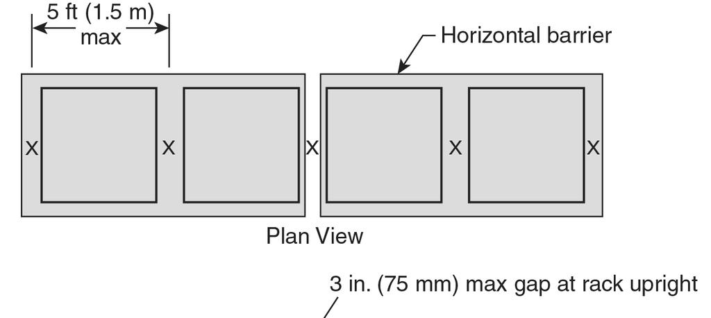
223
224 (B) The maximum linear spacing between sprinklers shall not exceed 5 ft (1.5 m) Double-Row Racks. (A) For double-row racks, sprinklers shall be installed at each rack upright within the longitudinal flue space and at the face of the rack and at the mid-bay face of each rack bay as shown in Figure (A). Figure (A) Alternative Protection Double-Row Racks.
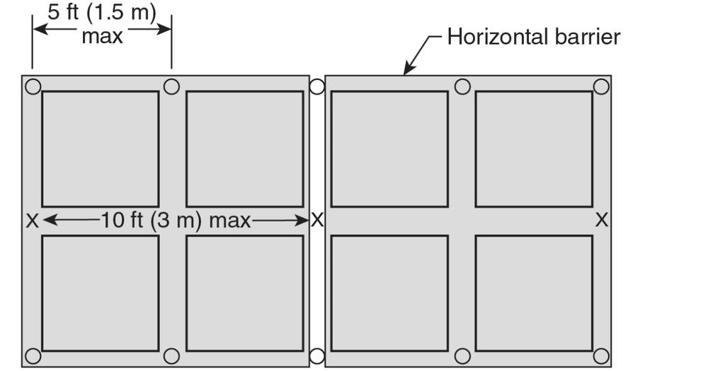
225
226 (B) The maximum linear spacing between sprinklers shall not exceed 5 ft (1.5 m) at the rack face and 10 ft (3.0 m) within the longitudinal flue space Multiple-Row Racks. (A) For multiple-row racks, an alternating sprinkler arrangement shall be installed within adjacent transverse flue spaces, as shown in Figure (A), with sprinklers at the face of each flue space. Figure (A) Alternative Protection Multiple-Row Racks.
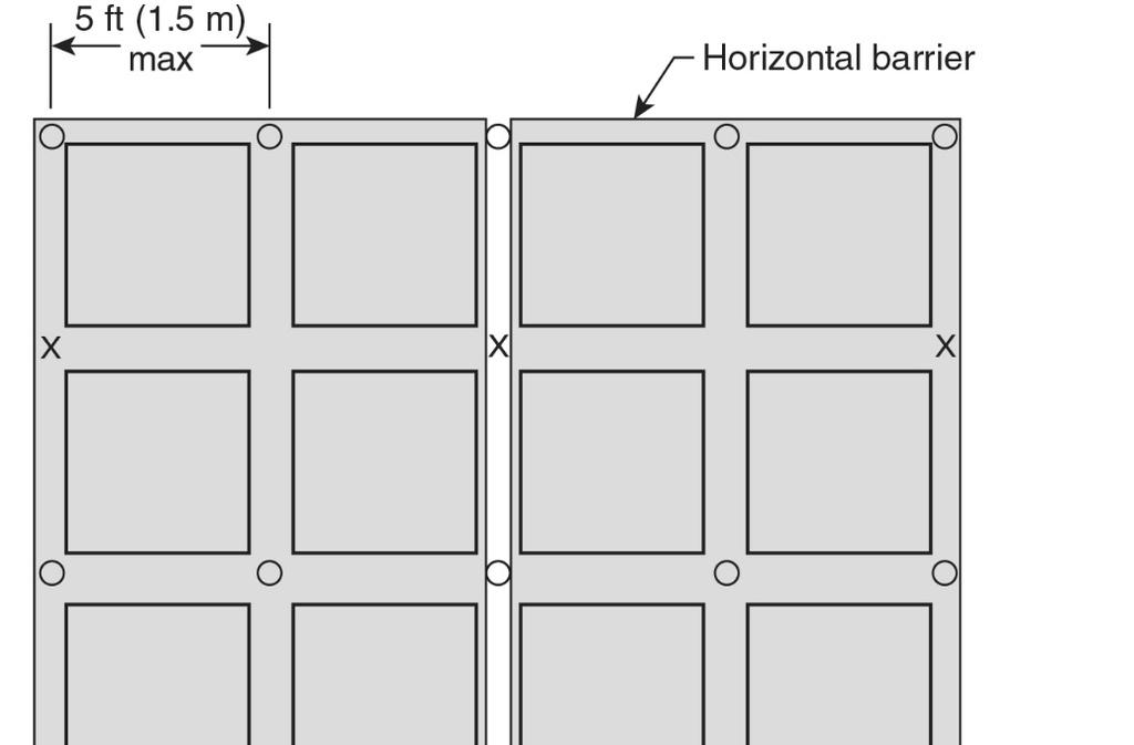
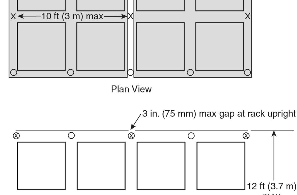
227
228 (B) The maximum linear spacing between sprinklers at the face and each alternating bay shall not exceed 5 ft (1.5 m) and shall not exceed 10 ft (3.0 m) between sprinklers at every other bay The design of an in-rack sprinkler system shall be based on a minimum flow of 60 gpm (230 L/min) from the most remote six sprinklers for single-row racks or the most remote eight sprinklers for both double-row and multiple-row racks The in-rack sprinkler demand shall not be required to be hydraulically balanced with the ceiling-level sprinkler system Ceiling Sprinkler System. The ceiling-level sprinkler system shall be designed based on the highest commodity hazard not protected by the criteria prescribed by Movable Racks. Rack storage in movable racks shall be protected in the same manner as multiple-row racks Fire Protection of Steel Columns Columns Within Storage Racks. See Section C * Where fireproofing of building columns is not provided and storage heights are in excess of 15 ft (4.6 m), protection of building columns located wholly or partially within the rack footprint inclusive of flue space or within 12 in. (305 mm) of the footprint shall be protected in accordance with one of the following: (1) In-rack sprinklers (2) Sidewall sprinklers at the 15 ft (4.6 m) elevation, pointed toward one side of the steel column (3) Provision of ceiling sprinkler density for a minimum of 2000 ft 2 (186 m 2 ) with ordinary temperature or high temperature rated sprinklers as shown in Table for storage heights above 15 ft (4.6 m) up to and including 20 ft (6.1 m) (4) Provision of CMSA or ESFR ceiling sprinkler protection Table Ceiling Sprinkler Densities for Protection of Steel Building Columns Aisle Width 4 ft (1.2 m) 8 ft (2.4 m) Commodity Classification gpm/ft 2 (L/min)/m 2 gpm/ft 2 (L/min)/m 2 Group A plastics Where storage heights are in excess of 15 ft (4.6 m) and vertical rack members support the building structure, the vertical rack members shall be protected in accordance with one of the options in The flow from a column sprinkler(s) shall be permitted to be omitted from the sprinkler system hydraulic calculations.
229 Solid Shelving Where solid shelving in single-, double-, and multiple-row racks exceeds 20 ft 2 (1.9 m 2 ) but does not exceed 64 ft 2 (5.9 m 2 ) in area, sprinklers shall not be required below every shelf, but shall be installed at the ceiling and below shelves at intermediate levels not more than 6 ft (1.8 m) apart vertically. (See Section C.11.) Where solid shelving in single-, double-, and multiple-row racks exceeds 64 ft 2 (5.9 m 2 ) in area or where the levels of storage exceed 6 ft (1.8 m), sprinklers shall be installed at the ceiling and below each level of shelving Where multiple-row racks of any height have no longitudinal flue or where double-row racks with storage up 25 ft (7.6 m) in height have no longitudinal flue, the situation shall not be considered solid shelves where transverse flues exist at maximum 5 ft (1.5 m) intervals and additional in-rack sprinklers shall not be required in accordance with and The maximum horizontal spacing between in-rack sprinklers shall be 5 ft (1.5 m) Ceiling design criteria for CMDA, CMSA, and ESFR sprinklers shall be an applicable option for open racks combined with in-rack sprinklers installed in accordance with the criteria for solid shelving Where the criteria in are not met, the water demand for the in-rack sprinklers shall be based on a minimum flow of 30 gpm (115 L/min) discharging from the following number of sprinklers balanced to the ceiling sprinkler demand in accordance with Section 23.8: (1) Eight sprinklers where only one level of in-rack sprinklers is installed (2) Fourteen sprinklers (seven on each of the top two levels) when more than one level of inrack sprinklers is installed The water demand for in-rack sprinklers shall not be required to be balanced to the ceiling sprinkler demand where additional face sprinklers are installed under each solid shelf at rack uprights and the in-rack sprinklers are calculated to discharge at least 60 gpm (230 L/min) from eight sprinklers Where solid shelves obstruct only a portion of the rack, in-rack sprinklers shall be installed horizontally, within the flue a minimum of 4 ft (1.2 m) beyond the end of the solid shelf, and vertically as follows: (1) In accordance with and for CMDA sprinklers (2) Beneath all tiers under the highest solid shelf for CMSA and ESFR sprinklers Open-Top Containers. The protection of open-top containers is outside the scope of Chapter 17. (See Section C.12.) In-Rack Sprinklers.
230 The number of sprinklers and the pipe sizing on a line of sprinklers in racks shall be restricted only by hydraulic calculations and not by any piping schedule When in-rack sprinklers are necessary to protect a higher hazard commodity that occupies only a portion of the length of a rack, in-rack sprinklers shall be extended a minimum of 8 ft (2.4 m) or one bay, whichever is greater, in each direction along the rack on either side of the higher hazard The in-rack sprinklers protecting the higher hazard shall not be required to be extended across the aisle Where a storage rack, due to its length, requires less than the number of in-rack sprinklers specified, only those in-rack sprinklers in a single rack need to be included in the calculation * Where in-rack sprinklers are installed in longitudinal flues, they shall be located at an intersection of transverse and longitudinal flues while not exceeding the maximum spacing rules Where distances between transverse flues exceed the maximum allowable distances, sprinklers shall be installed at the intersection of the transverse and longitudinal flues, and additional sprinklers shall be installed between transverse flues to meet the maximum distance rules Where no transverse flues exist, in-rack sprinklers shall not exceed the maximum spacing rules For storage over 25 ft in height, in-rack sprinklers in longitudinal flues shall be installed with the deflector located at or below the bottom of horizontal load beams or above or below other adjacent horizontal rack members, and such in-rack sprinklers shall be a minimum of 3 in. (76 mm) radially from the side of the rack uprights * Horizontal Barriers and In-Rack Sprinklers Horizontal barriers used in conjunction with in-rack sprinklers to impede vertical fire development shall be constructed of sheet metal, wood, or similar material and shall extend the full length and depth of the rack Barriers shall be fitted within 2 in. (50 mm) horizontally around rack uprights Flue Space Requirements for Storage Up to and Including 25 ft (7.6 m). See Section C In double- and multiple-row open racks, a longitudinal (back-to-back clearance between loads) flue space shall not be required.
231 Nominal 6 in. (150 mm) transverse flue spaces between loads and at rack uprights shall be maintained in single-, double-, and multiple-row racks Random variations in the width of flue spaces or in their vertical alignment shall be permitted Flue Space Requirements for Storage Over 25 ft (7.6 m) Nominal 6 in. (150 mm) longitudinal flue spaces shall be provided in double-row racks Nominal 6 in. (150 mm) transverse flue spaces between loads and at rack uprights shall be maintained in single-, double-, and multiple-row racks Random variations in the width of the flue spaces or in their vertical alignment shall be permitted Protection Criteria for Rack Storage of Group A Plastic Commodities Stored Up to and Including 25 ft (7.6 m) in Height * Storage 5 ft (1.5 m) or Less in Height. For the storage of Group A plastics stored 5 ft (1.5 m) or less in height, the sprinkler design criteria for miscellaneous storage specified in Chapter 13 shall be used For storage 5 ft (1.5 m) or less in height that does not meet the definition of Miscellaneous Storage that is on solid shelf racks, in-rack sprinklers shall be provided in accordance with , and ceiling sprinkler protection shall be provided in accordance with Chapter Ceiling Sprinkler Water Demand. See Section C In-Rack Sprinkler Requirements Where Control Mode Density/Area Sprinklers Are Being Used at Ceiling In-Rack Sprinkler Clearance. The minimum of 6 in. (150 mm) vertical clear space shall be maintained between the sprinkler deflectors and the top of a tier of storage. (A) Sprinkler discharge shall not be obstructed by horizontal rack members The spacing of in-rack sprinklers shall be in accordance with Figure (a) through Figure (f) * In-rack sprinklers shall be located at an intersection of transverse and longitudinal flues while not exceeding the maximum spacing rules.
232 Where distances between transverse flues exceed the maximum allowable distances, sprinklers shall be installed at the intersection of the transverse and longitudinal flues, and additional sprinklers shall be installed between transverse flues to meet the maximum distance rules Where no transverse flues exist, in-rack sprinklers shall not exceed the maximum spacing rules In-Rack Sprinkler Water Demand. The water demand for sprinklers installed in racks shall be based on simultaneous operation of the most hydraulically remote sprinklers as follows: (1) Eight sprinklers where only one level is installed in racks (2) Fourteen sprinklers (seven on each top two levels) where more than one level is installed in racks In-Rack Sprinkler Discharge Pressure. Sprinklers in racks shall discharge at not less than 15 psi (1.0 bar) for all classes of commodities. (See Section C.19.) CMSA Sprinklers for Rack Storage of Group A Plastic Commodities Stored Up to and Including 25 ft (7.6 m) in Height CMSA sprinklers shall not be permitted to protect storage on solid shelf racks unless the solid shelf racks are protected with in-rack sprinklers in accordance with Where solid shelves are used, in-rack sprinklers shall be installed in every level below the highest solid shelf Protection shall be provided as specified in Table or appropriate NFPA standards in terms of minimum operating pressure and the number of sprinklers to be included in the design area Open Wood Joist Construction Where CMSA sprinklers are installed under open wood joist construction, firestopping in accordance with shall be provided or the minimum operating pressure of the sprinklers shall be 50 psi (3.4 bar) for a K-11.2 (160) sprinkler or 22 psi (1.5 bar) for a K (240) sprinkler Where each joist channel of open wood joist construction is fully firestopped to its full depth at intervals not exceeding 20 ft (6.1 m), the lower pressures specified in Table shall be permitted to be used Preaction Systems. For the purpose of using Table , preaction systems shall be classified as dry pipe systems.
233 Building steel shall not require special protection where Table is applied as appropriate for the storage configuration In-Rack Sprinkler Requirements Where CMSA Sprinklers Are Used at Ceiling In-rack sprinklers shall be installed at the first tier level at or above one-half of the storage height The minimum of 6 in. (150 mm) vertical clear space shall be maintained between the sprinkler deflectors and the top of a tier of storage. (A) Sprinkler discharge shall not be obstructed by horizontal rack members * In-rack sprinklers shall be located at an intersection of transverse and longitudinal flues The maximum horizontal distance between in-rack sprinklers shall be 5 ft (1.5 m) Where distances between transverse flues exceed the maximum allowable distances, sprinklers shall be installed at the intersection of the transverse and longitudinal flues, and additional sprinklers shall be installed between transverse flues to meet the maximum distance rules Where no transverse flues exist, in-rack sprinklers shall not exceed the maximum spacing rules In-Rack Sprinkler Water Demand. The water demand for sprinklers installed in racks shall be based on simultaneous operation of the most hydraulically remote eight sprinklers In-Rack Sprinkler Discharge Pressure. Sprinklers in racks shall discharge at not less than 15 psi (1.0 bar) for all classes of commodities. (See Section C.19.) ESFR protection as defined shall not apply to the following: (1) Rack storage involving solid shelves, except as permitted by (2) Rack storage involving open-top cartons or containers ESFR sprinklers shall not be permitted to protect storage on solid shelf racks unless the solid shelf racks are protected with in-rack sprinklers in accordance with Where solid shelves are used, in-rack sprinklers shall be installed in every level below the highest solid shelf ESFR sprinkler systems shall be designed such that the minimum operating pressure is not less than that indicated in Table for type of storage, commodity, storage height, and building height involved.
234 The design area shall consist of the most hydraulically demanding area of 12 sprinklers, consisting of four sprinklers on each of three branch lines In-Rack Sprinkler Requirements Where ESFR Sprinklers Are Used at Ceiling Where required by Table , in-rack sprinklers shall be installed at the first tier level at or above one-half of the storage height In-rack sprinklers shall be K-8.0 (115) or K-11.2 (160) quick-response, ordinarytemperature sprinklers The minimum of 6 in. (150 mm) vertical clear space shall be maintained between the sprinkler deflectors and the top of a tier of storage. (A) Sprinkler discharge shall not be obstructed by horizontal rack members The maximum horizontal distance between in-rack sprinklers shall be 5 ft (1.5 m) * In-rack sprinklers shall be located at an intersection of transverse and longitudinal flues while not exceeding the maximum spacing rules Where distances between transverse flues exceed the maximum allowable distances, sprinklers shall be installed at the intersection of the transverse and longitudinal flues, and additional sprinklers shall be installed between transverse flues to meet the maximum distance rules Where no transverse flues exist, in-rack sprinklers shall not exceed the maximum spacing rules The water demand for sprinklers installed in racks shall be based on simultaneous operation of the most hydraulically remote eight sprinklers Each of the in-rack sprinklers described in shall discharge at a minimum of 60 gpm (227 L/min) Special Design for Rack Storage of Plastics Commodities Stored Up to and Including 25 ft (7.6 m) in Height Slatted Shelves * Slatted rack shelves shall be considered equivalent to solid rack shelves where the shelving is not considered open rack shelving or where the requirements of are not met. (See Section C.20.)
235 A wet pipe system that is designed to provide a minimum of 0.6 gpm/ft 2 (24.4 mm/min) density over a minimum area of 2000 ft 2 (186 m 2 ) or K-14.0 (200) ESFR sprinklers operating at a minimum of 50 psi (3.4 bar), K-16.8 (240) sprinklers operating at a minimum of 32 psi (2.2 bar), or K-25.2 (360) ESFR sprinklers operating at a minimum of 15 psi (1.0 bar) shall be permitted to protect single- and double-row racks with slatted rack shelving racks where all of the following conditions are met: (1) Sprinklers shall be K-11.2 (160), K-14.0 (200), or K-16.8 (240) orifice spray sprinklers with a temperature rating of ordinary, intermediate, or high and shall be listed for storage occupancies or shall be K-14.0 (200), K-16.8 (240), or K-25.2 (360) ESFR. (2) The protected commodities shall be limited to Class I through Class IV, Group B plastics, Group C plastics, cartoned (expanded and unexpanded) Group A plastics, and exposed (unexpanded) Group A plastics. (3) Slats in slatted rack shelving shall be a minimum nominal 2 in. (50 mm) thick by maximum nominal 6 in. (150 mm) wide with the slats held in place by spacers that maintain a minimum 2 in. (50 mm) opening between each slat. (4) Where K-11.2 (160), K-14.0 (200), or K-16.8 (240) orifice sprinklers are used, there shall be no slatted shelf levels in the rack above 12 ft (3.7 m). Open rack shelving using wire mesh shall be permitted for shelf levels above 12 ft (3.7 m). (5) Transverse flue spaces at least 3 in. (75 mm) wide shall be provided at least every 10 ft (3.0 m) horizontally. (6) Longitudinal flue spaces at least 6 in. (150 mm) wide shall be provided for double-row racks. Longitudinal flue spaces shall not be required when ESFR sprinklers are used. (7) The aisle widths shall be at least 71 2 ft (2.3 m). (8) The maximum roof height shall be 27 ft (8.2 m) or 30 ft (9.1 m) where ESFR sprinklers are used. (9) The maximum storage height shall be 20 ft (6.1 m). (10) Solid plywood or similar materials shall not be placed on the slatted shelves so that they block the 2 in. (50 mm) spaces between slats, nor shall they be placed on the wire mesh shelves Protection Criteria for Rack Storage of Group A Plastic Commodities Stored Over 25 ft (7.6 m) in Height For protection of cartoned storage of Group A plastics, expanded or unexpanded, whether encapsulated or nonencapsulated, on single-row racks, in-rack sprinklers shall be arranged in accordance with one of the options in Figure (a) through Figure (c) or Figure The highest level of in-rack sprinklers shall be not more than 10 ft (3.0 m) below the top of storage. Figure (a) In-Rack Sprinkler Arrangement, Group A Plastic Commodities, Single-Row Racks, Storage Height Over 25 ft (7.6 m) Option 1.
236 Figure (b) In-Rack Sprinkler Arrangement, Group A Plastic Commodities, Single-Row Racks, Storage Height Over 25 ft (7.6 m) Option 2.
237 Figure (c) In-Rack Sprinkler Arrangement, Group A Plastic Commodities, Single-Row Racks, Storage Height Over 25 ft (7.6 m) Option 3.
238 For protection of cartoned storage of Group A plastics, expanded or unexpanded, whether encapsulated or nonencapsulated, on double-row racks, in-rack sprinklers shall be arranged in accordance with one of the double-row rack options in Figure (a), Figure (b), or Figure The highest level of in-rack sprinklers shall be not more than 10 ft (3.0 m) below the top of storage.
 In-Rack Sprinkler Arrangement, Group A Plastic")
239 Figure (a) In-Rack Sprinkler Arrangement, Group A Plastic Commodities, Storage Height Over 25 ft (7.6 m) Option 1.
240 Figure (b) In-Rack Sprinkler Arrangement, Group A Plastic Commodities, Storage Height Over 25 ft (7.6 m) Option Where a single-row rack of cartoned Group A plastic storage is mixed with double-row racks of cartoned Group A plastic storage, either Figure (a) or Figure (b) shall be permitted to be used in accordance with the corresponding storage height. The highest level of in-rack sprinklers shall be not more than 10 ft (3.0 m) below the top of storage.
241 For protection of storage of exposed unexpanded Group A plastics, whether encapsulated or nonencapsulated, on single- racks or double-row racks, in-rack sprinklers shall be arranged in accordance with Figure The highest level of in-rack sprinklers shall be not more than 10 ft (3.0 m) below the top of storage. Where this figure is used, aisles shall be at least 4 ft (1.2 m) wide and the ceiling sprinklers shall be designed for a minimum discharge density of 0.45 gpm/ft 2 over 2000 ft 2 (18.3 mm/min over 186 m 2 ). Figure In-Rack Sprinkler Arrangement, Cartoned Expanded and Nonexpanded Group A Plastic and Exposed Nonexpanded Group A Plastic Commodities, Single- and Double-Row Racks, Storage Height Over 25 ft (7.6 m) * For protection of storage of exposed unexpanded Group A plastics, whether encapsulated or nonencapsulated, or cartoned Group A plastics, expanded or unexpanded, whether encapsulated or nonencapsulated, on multiple-row racks, in-rack sprinklers shall be arranged in accordance with one of the options in Figure (a) through Figure (f).
 below the top of storage. Figure 17.3.1.8(a) In-Rack Sprinkler Arrangement, Cartoned Group A Plastic and Exposed Nonexpanded Group A Plastic, Multiple-Row Racks, Storage Height Over 25 ft (7.")
242 The highest level of in-rack sprinklers shall be not more than 10 ft (3.0 m) below the top of storage. Figure (a) In-Rack Sprinkler Arrangement, Cartoned Group A Plastic and Exposed Nonexpanded Group A Plastic, Multiple-Row Racks, Storage Height Over 25 ft (7.6 m) Option 1 [10 ft (3.0 m) Maximum Spacing]. Figure (b) In-Rack Sprinkler Arrangement, Cartoned Group A Plastic and Exposed Nonexpanded Group A Plastic, Multiple-Row Racks, Storage Height Over 25 ft (7.6 m) Option 2 [10 ft (3.0 m) Maximum Spacing].
 In-Rack Sprinkler Arrangement, Cartoned Group A Plastic and Exposed Nonexpanded Group A")
243 Figure (c) In-Rack Sprinkler Arrangement, Cartoned Group A Plastic and Exposed Nonexpanded Group A Plastic, Multiple-Row Racks, Storage Height Over 25 ft (7.6 m) Option 1 [5 ft (1.5 m) Maximum Spacing].
244
245 Figure (d) In-Rack Sprinkler Arrangement, Cartoned Group A Plastic and Uncartoned Unexpanded Group A Plastic, Multiple-Row Racks, Storage Height Over 25 ft (7.6 m) Option 2 [5 ft (1.5 m) Maximum Spacing].
246 Figure (e) In-Rack Sprinkler Arrangement, Cartoned Group A Plastic and Exposed Nonexpanded Group A Plastic, Multiple-Row Racks, Storage Height Over 25 ft (7.6 m) Option 3 [5 ft (1.5 m) Maximum Spacing]. Figure (f) In-Rack Sprinkler Arrangement, Cartoned Group A Plastic and Exposed Nonexpanded Group A Plastic, Multiple-Row Racks, Storage Height Over 25 ft (7.6 m) Option 4 [5 ft (1.5 m) Maximum Spacing].
247 The minimum of 6 in. (150 mm) vertical clear space shall be maintained between the inrack sprinkler deflectors and the top of a tier of storage. (A) Sprinkler discharge shall not be obstructed by horizontal rack members.
248 * In-rack sprinklers shall be located at an intersection of transverse and longitudinal flues while not exceeding the maximum spacing rules Where distances between transverse flues exceed the maximum allowable distances, sprinklers shall be installed at the intersection of the transverse and longitudinal flues, and additional sprinklers shall be installed between transverse flues to meet the maximum distance rules Where no transverse flues exist, in-rack sprinklers shall not exceed the maximum spacing rules In-rack sprinklers shall be a minimum of 3 in. (76 mm) radially from the side of the rack uprights Face sprinklers in such racks shall be located within the rack a minimum of 3 in. (75 mm) from rack uprights and no more than 18 in. (450 mm) from the aisle face of storage In-Rack Sprinkler Water Demand. The water demand for sprinklers installed in racks shall be based on simultaneous operation of the most hydraulically remote sprinklers as follows: (1) Eight sprinklers where only one level is installed in racks (2) Fourteen sprinklers (seven on each top two levels) where more than one level is installed in racks In-Rack Sprinkler Discharge Pressure. Sprinklers in racks shall discharge at not less than 30 gpm (115 L/min) [move to ] The minimum water supply requirements for a hydraulically designed occupancy hazard fire control sprinkler system shall be determined by adding the hose stream allowance from Table to the water supply for sprinklers determined in Section Table Hose Stream Allowance and Water Supply Duration Requirements for Rack Storage of Group A Plastic Commodities Stored Over 25 ft (7.6 m) in Height Commodity Classification Plastic Storage Total Combined Inside Inside Hose Height and Outside Hose ft m gpm L/min gpm L/min 0, 50, or 0, 190, or >25 > Duration (minutes) CMSA Sprinklers for Rack Storage of Plastic Commodities Stored Over 25 ft (7.6 m) in Height Protection of single-, double-, and multiple-row rack storage for cartoned, unexpanded Group A plastic commodities shall be in accordance with Table
249 Table CMSA Sprinkler Design Criteria for Single-, Double-, and Multiple-Row Racks of Group A Plastic Commodities Stored Over 25 ft (7.6 m) in Height Storage Arrangement Single-, double-, and multiple-row racks (no open-top containers) Commodity Class Cartoned, unexpanded plastics Maximum Maximum Minimum Type Number Storage Ceiling/Roof K-Factor/ Operating of of Design Height Height Orientation Pressure System Sprinklers ft m ft m psi bar 19.6 (280) Wet Pendent (280) Pendent Wet CMSA sprinklers shall not be permitted to protect storage on solid shelf racks unless the solid shelf racks are protected with in-rack sprinklers in accordance with Where solid shelves are used, in-rack sprinklers shall be installed in every level below the highest solid shelf Protection shall be provided as specified in Table or appropriate NFPA standards in terms of minimum operating pressure and the number of sprinklers to be included in the design area [move to ] The design area shall be a rectangular area having a dimension parallel to the branch lines at least 1.2 times the square root of the area protected by the number of sprinklers to be included in the design area. Any fractional sprinkler shall be included in the design area Building steel shall not require special protection where Table is applied as appropriate for the storage configuration * In-Rack Sprinklers. (Reserved) * Early Suppression Fast-Response (ESFR) Sprinklers for Rack Storage of Group A Plastic Commodities Stored Over 25 ft (7.6 m) in Height Protection of single-, double-, and multiple-row rack storage of cartoned or exposed, unexpanded Group A plastic shall be in accordance with Table Table ESFR Protection of Rack Storage of Group A Plastic Commodities Stored Over 25 ft (7.6 m) in Height
250 Storage Arrangemen t Single-, double-, and multiple-row racks (no open-top containers) Commodit y Cartoned unexpanded Minimu Maximu m Maximum m Operatin Storage Ceiling/Roo Nomina g Height f Height l K- Orientatio Pressure ft m ft m Factor n psi bar 14.0 Upright/ (200) pendent No Upright/ No (240) pendent 22.4 Pendent No (320) 25.2 (360) Pendent No 16.8 (240) Pendent No (320) Pendent No 25.2 (360) Pendent No 14.0 (200) Pendent Yes (240) Pendent Yes 22.4 (320) Pendent No 25.2 (360) Pendent No (240) Pendent No 25.2 (360) Pendent No 14.0 Pendent Yes (200) Pendent Yes (240) Pendent No (320) 25.2 (320) Pendent No (200) Pendent Yes Pendent Yes 16.8 (240) In-Rack Sprinkler Requirement s
251 Storage Arrangemen Commodit t y Exposed unexpanded Minimu Maximu m Maximum m Operatin Storage Ceiling/Roo Nomina g Height f Height l K- Orientatio Pressure ft m ft m Factor n psi bar 22.4 (320) Pendent No 25.2 (360) Pendent No (200) Pendent No 16.8 (240) Pendent No 16.8 (240) Pendent No (320) Pendent No 25.2 (360) Pendent No (200) Pendent Yes 16.8 (240) Pendent Yes 16.8 (240) Pendent No (320) Pendent No (360) Pendent No (200) Pendent Yes 16.8 (240) Pendent Yes (200) Pendent Yes Pendent Yes 16.8 (240) In-Rack Sprinkler Requirement s ESFR sprinklers shall not be permitted to protect storage on solid shelf racks unless the solid shelf racks are protected with in-rack sprinklers in accordance with Where solid shelves are used, in-rack sprinklers shall be installed in every level below the highest solid shelf.
252 ESFR sprinklers shall not be permitted to protect storage with open-top containers ESFR sprinkler systems shall be designed such that the minimum operating pressure is not less than that indicated in Table for type of storage, commodity, storage height, and building height involved The design area shall consist of the most hydraulically demanding area of 12 sprinklers, consisting of four sprinklers on each of three branch lines Where required by Table , one level of K-8.0 (115) or K-11.2 (160) quickresponse, ordinary-temperature in-rack sprinklers shall be installed at the tier level closest to but not exceeding one-half of the maximum storage height In-rack sprinkler hydraulic design criteria shall be the most hydraulically remote eight sprinklers at 60 gpm (230 L/min) In-rack sprinklers shall be located at the intersection of the longitudinal and transverse flue space Horizontal spacing shall not be permitted to exceed 5 ft (1.5 m) intervals The minimum of 6 in. (150 mm) vertical clear space shall be maintained between the sprinkler deflectors and the top of a tier of storage. (A) Sprinkler discharge shall not be obstructed by horizontal rack members * In-rack sprinklers shall be located at an intersection of transverse and longitudinal flues while not exceeding the maximum spacing rules Where distances between transverse flues exceed the maximum allowable distances, sprinklers shall be installed at the intersection of the transverse and longitudinal flues, and additional sprinklers shall be installed between transverse flues to meet the maximum distance rules Where no transverse flues exist, in-rack sprinklers shall not exceed the maximum spacing rules In-rack sprinklers shall be a minimum of 3 in. (75 mm) radially from the side of the rack uprights Face sprinklers in such racks shall be located within the rack a minimum of 3 in. (75 mm) from rack uprights and no more than 18 in. (450 mm) from the aisle face of storage * Protection of Exposed Expanded Group A Plastics.
253 Protection of single-, double-, and multiple-row rack storage of exposed expanded Group A plastics shall be permitted to be in accordance with through The maximum storage height shall be 35 ft (11 m) The maximum ceiling height shall be 40 ft (12 m) Sprinklers shall be intermediate temperature rated ESFR pendent sprinklers with a nominal K-factor of K-25.2 (360) The design area shall consist of the most hydraulically demanding area of 12 sprinklers The minimum operating pressure shall be 60 psi (4.1 bar) The minimum aisle width shall be 8 ft (2.4 m) The rack shall have a solid vertical barrier of 3 8 in. (9.5 mm) plywood or particleboard, 22 gauge sheet metal, or equivalent, from face of rack to face of rack, spaced at a maximum 16.5 ft (5.0 m) interval The vertical barrier shall extend from a maximum of 4 in. (102 mm) above the floor to the maximum storage height The plan area of storage between vertical barriers and aisles shall not exceed 124 ft 2 (11.52 m 2 ) The vertical barrier shall extend across the longitudinal flue Commodity shall be permitted to extend a nominal 4 in. (102 mm) beyond the vertical barrier at the aisle.
254 National Fire Protection Association Report 38 of /14/ :55 AM First Revision No. 863-NFPA [ Global Input ] See attached word doc Supplemental Information File Name Chapter_18_Deletions.docx Description Submitter Information Verification Submitter Full Name: AUT-SSD Organization: National Fire Protection Assoc Street Address: City: State: Zip: Submittal Date: Wed Aug 31 09:02:53 EDT 2016 Committee Statement Committee Statement: Deletes text that was previously moving to Chapter 25. Response Message:
255 Chapter 18 Protection of Rubber Tire Storage 18.1 General. The requirements of Chapter 12 shall apply unless modified by this chapter In-Rack Sprinkler System Requirements for Protection of Rubber Tires. In-rack sprinklers, where provided, shall be installed in accordance with Chapter 17, except as modified by through The maximum horizontal spacing of sprinklers in racks shall be 8 ft (2.4 m) Water demand for sprinklers installed in racks shall be based on simultaneous operation of the most hydraulically remote 12 sprinklers where only one level is installed in racks Sprinklers in racks shall discharge at not less than 30 psi (2.1 bar).
256 National Fire Protection Association Report 39 of /14/ :55 AM First Revision No. 864-NFPA [ Global Input ] See attached word doc Supplemental Information File Name Chapter_23_Deletions.docx Description Submitter Information Verification Submitter Full Name: AUT-SSD Organization: National Fire Protection Assoc Street Address: City: State: Zip: Submittal Date: Wed Aug 31 09:03:50 EDT 2016 Committee Statement Committee Statement: Deletes text that was previously moving to Chapter 25. Response Message:
257 Chapter 23 Plans and Calculations Water demand of sprinklers installed in racks shall be added to ceiling sprinkler water demand over the same protected area at the point of connection The demand shall be balanced to the higher pressure.
258 National Fire Protection Association Report 40 of /14/ :55 AM First Revision No. 865-NFPA [ Global Input ] Add new Chapter 25 In-Rack Sprinkler Requirements. See attached word doc Supplemental Information File Name TG_25_Draft_Chapter_25_Without_Mark-Ups_10- Aug-2016_.docx Description Chapter 25 Protection of rack storage Using In-Rack Sprinklers Submitter Information Verification Submitter Full Name: AUT-SSD Organization: National Fire Protection Assoc Street Address: City: State: Zip: Submittal Date: Wed Aug 31 09:05:19 EDT 2016 Committee Statement Committee Statement: Based on the recommendation of the NFPA 13 Discharge Committee, the Chapters 24 and 25 Task Group put together a draft version of Chapter 25 with ceiling-level sprinkler designs included in the chapter so that flipping between Chapter 25 and other chapters could be minimized. The draft version of Chapter 25 was developed based on this concept and arranged so that there were no technical changes incorporated to the content of the chapter. However, the wording of many individual sections has been modified from its original language in an effort to create a common style of presenting the guidance. As a result, a majority of the wording from the 2016 edition has been modified, but only in the way the wording is presented, not in the technical guidance the wording provides. Response Message: Public Input No. 359-NFPA [Sections , ]
259 Task Group 25 Draft Version of Chapter Protection of Rack Storage Using In Rack Sprinklers 25.1 General Requirements of In Rack Sprinklers Scope. This section shall apply where rack storage of Class I through Class IV commodities, Group A plastic commodities, or rubber tires will be protected with in rack sprinklers Open Frame Storage Racks The in rack sprinkler arrangements as well as the ceiling and in rack sprinkler design criteria for rack storage in this chapter shall be based on open frame rack configurations as defined in unless indicated otherwise Where Group A commodities are being stored in racks with aisles less than 3.5 ft (1.1 m) wide, in rack sprinkler protection shall be in accordance with the guidelines for multiple row racks Where open frame double row racks with storage up 25 ft (7.6 m) in height have no longitudinal flue, but have transverse flues at maximum 5 ft (1.5 m) intervals, the double row rack storage arrangement shall be considered openframe Where multiple row racks of any height have no longitudinal flue, but have transverse flues at maximum 5 ft (1.5 m) intervals, the multiple row rack storage arrangement shall be considered open frame In Rack Sprinkler System In Rack Sprinkler System Size The area protected by a single in rack sprinkler system shall not exceed 40,000 ft² (3720 m²) of floor area occupied by the racks, including aisles, regardless of the number of in rack sprinkler levels An in rack sprinkler system shall be permitted to be supplied from the overhead ceiling sprinkler system where the area of the racks protected by the in rack sprinklers, including the adjacent aisles, do not exceed 8,000 ft² (740 m²) * In Rack Sprinkler System Control Valves A In rack sprinklers and ceiling sprinklers selected for protection should be controlled by at least two separate indicating valves and drains. In higher rack arrangements, consideration should be given to providing more than one inrack control valve in order to limit the extent of any single impairment Unless the requirements of or are met, separate indicating control valves and drains shall be provided and arranged so that ceiling and in rack sprinkler systems can be controlled independently A separate indicating control valve shall not be required where 20 or fewer in rack sprinklers are supplied by any one ceiling sprinkler system The separate indicating valves shall be permitted to be arranged as sectional control valves supplied from the ceiling sprinkler system where in rack sprinklers are required and the racks including the adjacent aisles occupy 8000 ft² (740m²) or less of the area protected by the ceiling sprinklers * Sprinkler Waterflow Alarm for In Rack Sprinklers. See Section C.4. A Central station, auxiliary, remote station, or proprietary protective signaling systems are a highly desirable supplement to local alarms, especially from a safety to life standpoint. (See ) Approved identification signs, as shown in Figure A , should be provided for outside alarm devices. The sign should be located near the device in a conspicuous position and should be worded as follows:
260 FIGURE A Identification Sign Flue Space Requirements for Racks Protected by In Rack Sprinklers Where in rack sprinklers are protecting rack storage, nominal 6 in. (150 mm) transverse flue spaces between loads and at rack uprights shall be maintained Where in rack sprinklers are protecting rack storage, random variations in the width of flue spaces or in their vertical alignment shall be permitted Where in rack sprinklers are protecting double and multiple row rack storage up to and including 25 ft (7.6 m) in height, a longitudinal (back to back clearance between loads) flue space shall not be required Where in rack sprinklers are protecting double row racks over 25 ft (7.6 m) in height, nominal 6 in. (150 mm) longitudinal flue spaces shall be provided Building Steel Protection. Where in rack sprinklers are installed in accordance with this chapter, building steel shall not require special protection Movable Racks. Rack storage in movable racks shall be protected in the same manner as multiple row racks Ceiling Level Sprinkler Design Criteria in Combination with In Rack Sprinklers General * This section shall apply to storage of materials, such as Class I through Class IV and Group A plastic commodity as well as rubber tires, representing the broad range of combustibles stored in racks that are being protected by in rack sprinklers. The requirements of Chapter 20 shall apply unless modified by this chapter. (See Section C.9.) A The fire protection system design should consider the maximum storage height. For new sprinkler installations, maximum storage height is the usable height at which commodities can be stored above the floor while the minimum required unobstructed space below sprinklers is maintained. Where evaluating existing situations, maximum storage height is the maximum existing storage height if space between the sprinklers and storage is equal to or greater than that required * Ceiling level sprinkler design criteria for single, double, and multiple row racks in 25.2 shall be based on open rack configurations as defined in A Solid shelf racks as defined in or obstructions resulting in solid shelf requirements could require additional in rack sprinklers that could affect the ceiling design requirements * Ceiling level sprinkler design criteria for Group A plastic commodities in this chapter shall be permitted for the protection of the same storage height and configuration of Class I, II, III, and IV commodities. A Information for the protection of Classes I, II, III, and IV commodities was extrapolated from full scale fire tests that were performed at different times than the tests that were used to develop the protection for plastic commodities. It is possible that, by selecting certain points from the tables (and after applying the appropriate modifications), the protection specified by for Class I through Class IV commodities exceeds the requirements for Group A plastic commodities. In such situations, the protection specified for plastics, although less than that required by the tables, can adequately protect Class I, II, III, and IV commodities. This section also allows storage areas that are designed to protect plastic commodities to store Class I, II, III, and IV commodities without a reevaluation of fire protection systems Ceiling level sprinkler design criteria for single and double row rack storage of Group A plastic commodities shall be applicable where aisles are 3.5 ft (1.1 m) or greater in width Ceiling level sprinkler design criteria for rack storage of Group A plastic commodities shall be protected as multiple row racks where aisles are less than 3.5 ft (1.1 m) in width.
261 The minimum water supply requirements for a hydraulically designed occupancy hazard automatic ceilinglevel sprinkler system shall be determined by adding the hose stream allowance from Table to the water supply for in rack sprinklers determined in Section 25.12, unless indicated otherwise Miscellaneous and Low Piled Storage Miscellaneous Storage This section shall apply to any of the following situations: (1) Miscellaneous storage of Class I through Class IV commodities up to and including 12 ft (3.7 m) in height (2) Miscellaneous storage of Group A plastic commodities up to and including 12 ft (3.7 m) in height (3) Miscellaneous storage of rubber tires up to and including 12 ft (3.7 m) in height Where in rack sprinklers are installed in accordance with Section 25.4 through Section 25.7 to protect miscellaneous rack storage of Class I through Class IV and Group A plastic commodities, as well as miscellaneous rack storage of rubber tires, up to and including 12 ft (3.7 m) in height under a maximum 32 ft (10.0 m) high ceiling, the ceiling level sprinkler design criteria shall be in accordance with Figure FIGURE CMDA Ceiling Level Sprinkler Design Criteria for Miscellaneous Storage Protected with One Level of In Rack Sprinklers Installation criteria as permitted by NFPA 13 and design criteria and modifiers as permitted by the density/area method of Section 19.2 for ordinary hazard Group 2 occupancies shall be applicable Hose Connections. Hose connections shall not be required for the protection of miscellaneous storage Low Piled Storage This section shall apply to any of the following situations: (1) Storage of Class I through Class IV commodities up to 12 ft and including (3.7 m) in height (2)* Storage of Group A plastic commodities up to and including 5 ft (1.5 m) in height. A (2) All rack fire tests of plastic commodities were run with an approximate 10 ft (3.0 m) maximum clearance to ceiling For low piled rack storage with solid shelves of Class I through Class IV commodities up to and including 12 ft (3.7 m) in height, in rack sprinklers shall be provided in accordance with Section 25.6, and the ceiling level sprinkler design shall be in accordance with Figure For low piled rack storage with solid shelves of Group A plastic commodities up to and including 5 ft (1.5 m) in height, in rack sprinklers shall be provided in accordance with 25.6, and the ceiling level sprinkler design shall be in accordance with Figure CMDA Ceiling Level Sprinkler Design Criteria in Combination with In Rack Sprinklers General Ceiling level sprinkler design criteria for the rack storage of Class I through Class IV commodities shall be in accordance with Section for storage over 12 ft (3.7 m) and up to and including 25 ft (7.6 m) in height and Section for storage over 25 ft (7.6 m) in height Ceiling level sprinkler design criteria for the rack storage of Group A plastic commodities shall be in accordance with Section for storage over 5 ft (1.5 m) and up to and including 25 ft (7.6 m) in height and Section for storage over 25 ft (7.6 m) in height.
262 This chapter also shall be used to determine protection for commodities that are not entirely Group A plastic commodities but contain such quantities and arrangements of Group A plastic commodities that they are deemed more hazardous than Class IV commodities Rack Storage of Class I Through Class IV Commodities Stored Over 12 ft (3.7 m) and Up to and Including 25 ft (7.6 m) in Height * Single and Double Row Racks. For single or double row rack storage of Class I through Class IV commodities, encapsulated or nonencapsulated, stored over 12 ft (3.7 m) and up to and including 25 ft (7.6 m) in height, Table shall be used to determine the appropriate figure for determining ceiling level sprinkler design criteria with the provision of one level of in rack sprinklers. A Bulkheads are not a substitute for sprinklers in racks. Their installation does not justify reduction in sprinkler densities or design operating areas as specified in the design curves. TABLE Determining Appropriate Ceiling Level Protection Criteria Figure for Single or Double Row Racks of Class I through Class IV Commodities Storage Height Over 12 ft (3.7 m) Up to and Including 25 ft (7.6 m) Multiple Row Racks
263 For multiple row racks, having a rack depth up to and including 16 ft (4.9 m) with aisles 8 ft (2.4 m) or wider, storing Class I through Class IV commodities, encapsulated or nonencapsulated, over 12 ft (3.7 m) and up to and including 25 ft (7.6 m) in height, Table shall be used to determine the appropriate figure for determining ceiling level sprinkler design criteria with the provision of one level of in rack sprinklers. TABLE Determining Appropriate Ceiling Level Protection Criteria Figure for Multiple Row Racks of Class I through Class IV Commodities Rack Depth Up to and Including 16 ft (4.9 m), Aisles 8 ft (2.4 m) or Wider and Storage Height Over 12 ft (3.7 m) Up to 25 ft (7.6 m) For multiple row racks, having a rack depth up to and including 16 ft (4.9 m) with aisles 8 ft (2.4 m) or wider, storing Class I through Class IV commodities, encapsulated or nonencapsulated, over 12 ft (3.7 m) and up to and including 25 ft (7.6 m) in height, Table shall be used to determine the appropriate figure for determining ceiling level sprinkler design criteria with the provision of one level of in rack sprinklers.
264 TABLE Determining Appropriate Ceiling Level Protection Criteria Figure for Multiple Row Racks of Class I through Class IV Commodities Rack Depth Over 16 ft (4.9 m) or Aisles Narrower Than 8 ft (2.4 m), Storage Height Over 12 ft (3.7 m) Up to and Including 25 ft (7.6 m) Ceiling Level Protection Criteria Figures * The ceiling level sprinkler design criteria in terms of density [gpm/ft² (mm/min)] and area of sprinkler operation [ft² (m²) of ceiling or roof] obtained from the appropriate density/area curves of Figure (a) through Figure (g) shall be modified as appropriate by These requirements shall apply to portable racks arranged in the same manner as single, double or multiple row racks. (See Section C.14.) A Data indicate that the sprinkler protection criteria in Figure (a) through Figure (g) are ineffective, by themselves, for rack storage with solid shelves, if the required flue spaces are not maintained. Use of Figure (a) through Figure (g), along with the additional provisions that are required by this standard, can provide acceptable protection.
265 * Design densities obtained from Figure (a) through Figure (g) for single and doublerow racks shall be selected to correspond to aisle width. (See Section C.15.) (A) For aisle widths between 4 ft (1.2 m) and 8 ft (2.4 m), the rules for 4 ft (1.2 m) aisle width shall be used or direct linear interpolation between the densities shall be permitted (B) The density given for 8 ft (2.4 m) wide aisles shall be applied to aisles wider than 8 ft (2.4 m) (C) The density given for 4 ft (1.2 m) wide aisles shall be applied to aisles more narrow than 4 ft (1.2 m) down to (1.1 m) (D) Where aisles are more narrow than (1.1 m), racks shall be considered to be mul ple row racks. A The aisle width and the depth of racks are determined by material handling methods. The widths of aisles should be considered in the design of the protection system. Storage in aisles can render protection ineffective and should be discouraged. FIGURE (a) CMDA Sprinkler System Design Curves 20 ft (6.1 m) High Rack Storage Class I Nonencapsulated Commodities Conventional Pallets. FIGURE (a)(A) Single or double row racks with 8 ft (2.4 m) aisles with high temperature ceiling sprinklers and ordinary temperature in rack sprinklers FIGURE (a)(B) Single or double row racks with 8 ft (2.4 m) aisles with ordinary temperature ceiling sprinklers and ordinary temperature in rack sprinklers FIGURE (a)(C) Single or double row racks with 4 ft (1.2 m) aisles or multiple row racks with high temperature ceiling sprinklers and ordinary temperature in rack sprinklers FIGURE (a)(D) Single or double row racks with 4 ft (1.2 m) aisles or multiple row racks with ordinarytemperature ceiling sprinklers and ordinary temperature in rack sprinklers FIGURE (b) CMDA Sprinkler System Design Curves 20 ft (6.1 m) High Rack Storage Class II Nonencapsulated Commodities Conventional Pallets. FIGURE (b)(A) Single or double row racks with 8 ft (2.4 m) aisles with high temperature ceiling sprinklers and ordinary temperature in rack sprinklers FIGURE (b)(B) Single or double row racks with 8 ft (2.4 m) aisles with ordinary temperature ceiling sprinklers and ordinary temperature in rack sprinklers FIGURE (b)(C) Single or double row racks with 4 ft (1.2 m) aisles or multiple row racks with high temperature ceiling sprinklers and ordinary temperature in rack sprinklers FIGURE (b)(D) Single or double row racks with 4 ft (1.2 m) aisles or multiple row racks with ordinarytemperature ceiling sprinklers and ordinary temperature in rack sprinklers FIGURE (c) CMDA Sprinkler System Design Curves 20 ft (6.1 m) High Rack Storage Class III Nonencapsulated Commodities Conventional Pallets. FIGURE (c)(A) Single or double row racks with 8 ft (2.4 m) aisles with high temperature ceiling sprinklers and ordinary temperature in rack sprinklers FIGURE (c)(B) Single or double row racks with 8 ft (2.4 m) aisles with ordinary temperature ceiling sprinklers and ordinary temperature in rack sprinklers FIGURE (c)(C) Single or double row racks with 4 ft (1.2 m) aisles or multiple row racks with high temperature ceiling sprinklers and ordinary temperature in rack sprinklers FIGURE (c)(D) Single or double row racks with 4 ft (1.2 m) aisles or multiple row racks with ordinarytemperature ceiling sprinklers and ordinary temperature in rack sprinklers
266 FIGURE (d) CMDA Sprinkler System Design Curves 20 ft (6.1 m) High Rack Storage Class IV Nonencapsulated Commodities Conventional Pallets. FIGURE (d)(A) Single or double row racks with 8 ft (2.4 m) aisles with high temperature ceiling sprinklers and ordinary temperature in rack sprinklers FIGURE (d)(B) Single or double row racks with 8 ft (2.4 m) aisles with ordinary temperature ceiling sprinklers and ordinary temperature in rack sprinklers FIGURE (d)(C) Single or double row racks with 4 ft (1.2 m) aisles or multiple row racks with high temperature ceiling sprinklers and ordinary temperature in rack sprinklers FIGURE (d)(D) Single or double row racks with 4 ft (1.2 m) aisles or multiple row racks with ordinarytemperature ceiling sprinklers and ordinary temperature in rack sprinklers FIGURE (e) CMDA Sprinkler System Design Curves Single or Double Row Racks 20 ft (6.1 m) High Rack Storage Class I and Class II Encapsulated Commodities Conventional Pallets. FIGURE (e)(A) 8 ft (2.4 m) aisles with high temperature ceiling sprinklers and ordinary temperature in rack sprinklers FIGURE (e)(B) 8 ft (2.4 m) aisles with ordinary temperature ceiling sprinklers and ordinary temperature inrack sprinklers FIGURE (e)(C) 4 ft (1.2 m) aisles with high temperature ceiling sprinklers and ordinary temperature in rack sprinklers FIGURE (e)(D) 4 ft (1.2 m) aisles with ordinary temperature ceiling sprinklers and ordinary temperature inrack sprinklers FIGURE (f) CMDA Sprinkler System Design Curves Single or Double Row Racks 20 ft (6.1 m) High Rack Storage Class III Encapsulated Commodities Conventional Pallets. FIGURE (f)(A) 8 ft (2.4 m) aisles with high temperature ceiling sprinklers and ordinary temperature in rack sprinklers FIGURE (f)(B) 8 ft (2.4 m) aisles with ordinary temperature ceiling sprinklers and ordinary temperature inrack sprinklers FIGURE (f)(C) 4 ft (1.2 m) aisles with high temperature ceiling sprinklers and ordinary temperature in rack sprinklers FIGURE (f)(D) 4 ft (1.2 m) aisles with ordinary temperature ceiling sprinklers and ordinary temperature inrack sprinklers FIGURE (g) CMDA Sprinkler System Design Curves Single or Double Row Racks 20 ft (6.1 m) High Rack Storage Class IV Encapsulated Commodities Conventional Pallets. FIGURE (g)(A) 8 ft (2.4 m) aisles with high temperature ceiling sprinklers and ordinary temperature in rack sprinklers FIGURE (g)(B) 8 ft (2.4 m) aisles with ordinary temperature ceiling sprinklers and ordinary temperature inrack sprinklers FIGURE (g)(C) 4 ft (1.2 m) aisles with high temperature ceiling sprinklers and ordinary temperature in rack sprinklers FIGURE (g)(D) 4 ft (1.2 m) aisles with ordinary temperature ceiling sprinklers and ordinary temperature inrack sprinklers * Ceiling Sprinkler Density Adjustments.
267 A The adjustments in apply to solid shelves where the minimum required level of in rack sprinklers from an open rack option is exceeded Where Class I, Class II, and Class III commodities are encapsulated in multiple row racks over 12 ft (3.7 m) and up to and including 25 ft (7.6 m) in height, the ceiling sprinkler density obtained from the applicable figure in shall be increased by 25 percent over that required for nonencapsulated commodities Where Class IV commodities are encapsulated in multiple row racks over 12 ft (3.7 m) and up to and including 25 ft (7.6 m) in height, the ceiling sprinkler density obtained from the applicable figure in shall be increased by 50 percent over that required for nonencapsulated Where in rack sprinklers are being installed within racks of Class I through Class IV commodities stored over 12 ft (3.7 m) up to and including 20 ft (6.1 m) protected with CMDA sprinklers at ceiling level along with the minimum number of required in rack sprinkler levels, densities obtained from design curves shall be adjusted in accordance with Figure FIGURE Adjustment to Ceiling Level Sprinkler Density Due to Storage Height Where in rack sprinklers are being installed within racks of Class I through Class IV commodities stored over 12 ft (3.7 m) and up to and including 20 ft (6.1 m) in height protected with CMDA sprinklers at ceiling level along with more than one level of in rack sprinklers, but not in every tier, densities obtained from design curves and adjusted in accordance with Figure shall be permitted to be reduced an additional 20 percent, as indicated in Table TABLE Adjustment to Ceiling Level Sprinkler Density Due to Storage Height and In Rack Sprinklers * Where in rack sprinklers are being installed within racks of Class I through Class IV commodities stored over 12 ft (3.7 m) and up to and including 20 ft (6.1 m) in height protected with CMDA sprinklers at ceiling level along with in rack sprinklers at each tier level, densities obtained from design curves and adjusted in accordance with Figure shall be permitted to be reduced an additional 40 percent, as indicated in Table A It is not the intent that an in rack sprinkler be installed above the top tier of storage when utilizing inrack sprinklers at each tier level Where in rack sprinklers are being installed within racks of Class I through Class IV commodities stored over 20 ft (6.1 m) and up to and including 25 ft (7.6 m) in height protected with CMDA sprinklers at ceiling level along
268 with the minimum number of required in rack sprinkler levels, densities obtained from design curves shall be used. Densities shall not be adjusted in accordance with Figure Where in rack sprinklers are being installed within racks of Class I through Class IV commodities stored over 20 ft (6.1 m) and up to and including 25 ft (7.6 m) in height protected with CMDA sprinklers at ceiling level along with more than the minimum required level of in rack sprinklers, but not in every tier, densities obtained from design curves shall be permitted to be reduced 20 percent, as indicated in Table Densities shall not be adjusted in accordance with Figure for storage height Where in rack sprinklers are being installed within racks of Class I through Class IV commodities stored over 20 ft (6.1 m) and up to and including 25 ft (7.6 m) in height protected with CMDA sprinklers at ceiling level along with in rack sprinklers at each tier level, except above the top tier, densities obtained from design curves shall be permitted to be reduced 40 percent, as indicated in Table Densities shall not be adjusted in accordance with Figure for storage height Rack Storage of Class I Through Class IV Commodities Over 25 ft (7.6 m) in Height Single and Double Row Racks * Where in rack sprinklers are being installed within single and double row racks separated by aisles at least 4 ft (1.2 m) wide and with a clearance to ceiling up to and including 10 ft (3.0 m) of nonencapsulated Class I through Class IV commodities stored over 25 ft (7.6 m) in height protected by CMDA sprinklers at ceiling level, the ceiling sprinkler designs shall be in accordance with Table A Water demand for storage height over 25 ft (7.6 m) on racks separated by aisles at least 4 ft (1.2 m) wide and with more than 10 ft (3.0 m) between the top of storage and the sprinklers should be based on sprinklers in a 2000 ft² (186 m²) operating area for double row racks and a 3000 ft² (279 m²) operating area for multiple row racks discharging a minimum of 0.18 gpm/ft² (7.3 mm/min) for Class I commodities, 0.21 gpm/ft² (8.5 mm/min) for Class II and Class III commodities, and 0.25 gpm/ft² (10.2 mm/min) for Class IV commodities for ordinary temperature rated sprinklers or a minimum of 0.25 gpm/ft² (10.2 mm/min) for Class I commodities, 0.28 gpm/ft² (11.4 mm/min) for Class II and Class III commodities, and 0.32 gpm/ft² (13 mm/min) for Class IV commodities for high temperature rated sprinklers. (See A ) Where such storage is encapsulated, ceiling sprinkler density should be 25 percent greater than for nonencapsulated storage. Data indicate that the sprinkler protection criteria in are ineffective, by themselves, for rack storage with solid shelves if the required flue spaces are not maintained. Use of , along with the additional provisions that are required by this standard, can provide acceptable protection. TABLE CMDA Ceiling Level Sprinkler Design Criteria for Single or Double Row Racks of Nonencapsulated Class I Through Class IV Commodities Stored Over 25 ft (7.6 m) in Height with Aisles 4 ft (1.2 m) or More in Width, Clearance to Ceiling Up to and Including 10 ft (3.0 m) Supplemented With In Rack Sprinklers Where storage as described in is encapsulated, the ceiling sprinkler density obtained from Table shall be increased by 25 percent over that required for nonencapsulated commodities Multiple Row Racks.
269 Where in rack sprinkler are being installed within multiple row racks separated by aisles at least 4 ft (1.2 m) wide and with a clearance to ceiling up to and including 10 ft (3.0 m) of nonencapsulated Class I through Class IV commodities stored over 25 ft (7.6 m) in height protected by CMDA sprinklers at ceiling level, the ceiling sprinkler designs shall be in accordance with Table TABLE CMDA Ceiling Level Sprinkler Design Criteria for Multiple Row Racks of Nonencapsulated Class I Through Class IV Commodities Stored Over 25 ft (7.6 m) in Height, Clearance to Ceiling Up to and Including 10 ft (3.0 m) Supplemented With In Rack Sprinklers Where storage as described in is encapsulated, the ceiling sprinkler density obtained from Table shall be increased by 25 percent over that required for nonencapsulated commodities Rack Storage of Group A Plastic Commodities Stored Over 5 ft (1.5 m) and Up to and Including 25 ft (7.6 m) in Height Cartoned Group A Plastic Commodities Where rack storage of cartoned Group A plastic commodities, encapsulated or nonencapsulated, having a clearance to ceiling up to and including 10 ft (3.0 m) is protected by in rack sprinklers, ceiling level sprinkler designs in terms of density [gpm/ft² (mm/min)] and area of operation [ft² (m²)] shall be selected from Figure (a) through Figure (e) Linear interpolation of design densities and areas of application shall be permitted between storage heights with the same clearance to ceiling No interpolation between clearance to ceiling shall be permitted Exposed Unexpanded Group A Plastic Commodities. Where in rack sprinkler protection is installed to protect rack storage of exposed unexpanded Group A plastic commodities, encapsulated or nonencapsulated, stored over 5 ft (1.5 m) and up to and including 25 ft (7.6 m) in height protected by CMDA sprinklers at ceiling level, the ceiling sprinkler design shall be in accordance with one of the following: (1) Where in rack sprinklers are installed in accordance with Figure (a), the ceiling level sprinkler design shall be a minimum 0.45 gpm/ft² (18.3 mm/min) density over a 2000 ft² (186 m²) demand area (2) Where in rack sprinklers are installed in accordance with Figure (b), the ceiling level sprinkler design shall be a minimum 0.30 gpm/ft² (12.2 mm/min) density over a 2000 ft² (186 m²) demand area (3) Where in rack sprinklers are installed in accordance with Figure (c), the ceiling level sprinkler design shall be a minimum 0.45 gpm/ft² (18.3 mm/min) density over a 2000 ft² (186 m²) demand area (4) Where in rack sprinklers are installed in accordance with Figure (d), the ceiling level sprinkler design shall be a minimum 0.30 gpm/ft² (12.2 mm/min) density over a 2000 ft² (186 m²) demand area (5) Where in rack sprinklers are installed in accordance with Figure (e), the ceiling level sprinkler design shall be a minimum 0.6 gpm/ft² (24.4 mm/min) density over a 2000 ft² (186 m²) demand area.
270 (6) Where in rack sprinklers are installed in accordance with Figure (f), the ceiling level sprinkler design shall be a minimum 0.45 gpm/ft² (18.3 mm/min) density over a 2000 ft² (186 m²) demand area (7) Where in rack sprinklers are installed in accordance with Figure (g), the ceiling level sprinkler design shall be a minimum 0.8 gpm/ft² (32.6 mm/min) density over a 1500 ft² (139 m²) demand area (8) Where in rack sprinklers are installed in accordance with Figure (h), the ceiling level sprinkler design shall be a minimum 0.6 gpm/ft² (24.4 mm/min) density over a 1500 ft² (139 m²) demand area (9) Where in rack sprinklers are installed in accordance with Figure (i), the ceiling level sprinkler design shall be a minimum 0.30 gpm/ft² (12.2 mm/min) density over a 2000 ft² (186 m²) demand area (10) Where in rack sprinklers are installed in accordance with Figure (j), the ceiling level sprinkler design shall be a minimum 0.8 gpm/ft² (32.6 mm/min) density over a 1500 ft² (139 m²) demand area (11) Where in rack sprinklers are installed in accordance with Figure (k), the ceiling level sprinkler design shall be a minimum 0.30 gpm/ft² (12.2 mm/min) density over a 2000 ft² (186 m²) demand area * Rack Storage of Group A Plastic Commodities Stored Over 25 ft (7.6 m) in Height. Where rack storage of Group A plastic commodities, encapsulated or nonencapsulated, over 25 ft (7.6 m) in height are protected by in rack sprinklers in accordance with , ceiling level sprinkler designs, in terms of density [gpm/ft² (mm/min)] and area of operation [ft² (m²)], shall be selected from Table based on the storage height of commodity above the top level of in rack sprinklers. A In this application ordinary, intermediate, or high temperature ceiling level sprinklers can be used. There are no data to support temperature rating restrictions for this section. TABLE CMDA Ceiling Level Sprinkler Design Criteria for Rack Storage of Group A Plastic Commodities with Storage Over 25 ft (7.6 m) in Height, Clearance to Ceiling Up to and Including 10 ft (3.0 m) Supplemented with In Rack Sprinklers Rack Storage of Rubber Tires Stored Over 12 ft (3.7 m) in Height General. The requirements of Chapter 20 shall apply unless modified in this section * Ceiling Systems. Where rack storage of rubber tires, either on side or on tread, over 5 ft (1.5 m) and up to and including 20 ft (6.1 m) in height protected by CMDA sprinklers at ceiling level with a maximum clearance to ceiling of 10 ft (3.0 m) along with one level of in rack sprinklers, the ceiling level sprinkler system design density and area of application shall be a minimum 0.40 gpm/ft² (16.3 mm/min) density over a 3000 ft² (279 m²) demand area. A See A Reduced Discharge Density. Where high expansion foam systems are installed in accordance with NFPA 11 to protect rack storage of rubber tires, either on side or on tread, over 5 ft (1.5 m) and up to and including 20 ft (6.1 m) in height protected by CMDA sprinklers at ceiling level with a maximum clearance to ceiling of 10 ft (3.0 m) and one
271 level of in rack sprinklers, the ceiling level sprinkler system design density shall be permitted to be reduced from 0.40 gpm/ft² (16.3 mm/min) 0.24 gpm/ft² (9.8 mm/min) Water Supplies. Total water supplies shall be capable of providing flow for automatic sprinklers, hose streams, and foam systems (if provided) for the duration required in Table CMSA Ceiling Level Sprinkler Design Criteria in Combination with In Rack Sprinklers General Open Wood Joist Construction with CMSA Sprinklers at Ceiling Level Where CMSA sprinklers are installed under open wood joist construction, fire stopping in accordance with shall be provided or the minimum operating pressure of the sprinklers shall be 50 psi (3.4 bar) for a K 11.2 (160) sprinkler or 22 psi (1.5 bar) for a K 16.8 (240) sprinkler Where each joist channel of open wood joist construction is fully fire stopped to its full depth at intervals not exceeding 20 ft (6.1 m), the lower pressures specified in Table shall be permitted to be used Preaction Systems for CMSA Sprinklers. For the purpose of using Table , preaction systems shall be classified as dry pipe systems Rack Storage of Class I Through Class IV Commodities Where rack storage of Class I through Class IV commodities is protected by CMSA sprinklers at ceiling level along with one level of in rack sprinklers, the ceiling level sprinkler design criteria shall be in accordance with Table TABLE CMSA Ceiling Level Sprinkler Design Criteria for Rack Storage of Class I Through Class IV Commodities (Encapsulated and Nonencapsulated) Supplemented with In Rack Sprinklers Protection shall be provided as specified in Table or appropriate NFPA standards in terms of minimum operating pressure and the number of ceiling level sprinklers to be included in the design area Rack Storage of Group A Plastic Commodities.
272 Where rack storage of unexpanded, cartoned and uncartoned, Group A plastic commodities is protected by CMSA sprinklers at ceiling level along with one level of in rack sprinklers, the ceiling level sprinkler system design criteria shall be in accordance with Table TABLE CMSA Ceiling Level Sprinkler Design Criteria for Rack Storage of Group A Plastic Commodities Stored Up and Including 25 ft (7.6 m) in Height Supplemented with In Rack Sprinklers Protection shall be provided as specified in Table or appropriate NFPA standards in terms of minimum operating pressure and the number of ceiling level sprinklers to be included in the design area ESFR Ceiling Level Sprinkler Design Criteria in Combination with In Rack Sprinklers Rack Storage of Class I Through Class IV Commodities Where rack storage of Class I through Class IV commodities is protected by ESFR sprinklers at ceiling level along with one level of in rack sprinklers, the ceiling level sprinkler design criteria shall be in accordance with Table TABLE ESFR Ceiling Level Sprinkler Design Criteria for Rack Storage of Class I Through Class IV Commodities (Encapsulated and Nonencapsulated) Supplemented with In Rack Sprinklers ESFR sprinkler systems, when supplemented with in rack sprinklers, shall be designed such that the minimum operating pressure is not less than that indicated in Table for type of storage, commodity, storage height, and building height involved The design area applicable to the ceiling level design options listed in Table 25.xx shall consist of the most hydraulically demanding area of 12 sprinklers, consisting of four sprinklers on each of three branch lines Rack Storage of Group A Plastic Commodities Where rack storage of cartoned or exposed unexpanded Group A plastic and cartoned expanded Group A plastic commodity is protected by ESFR sprinklers at ceiling level along with one level of in rack sprinklers, the ceilinglevel sprinkler design criteria shall be in accordance with Table TABLE ESFR Ceiling Level Sprinkler Design Criteria for Rack Storage of Group A Plastic Commodities Supplemented with In Rack Sprinklers
273 ESFR sprinkler systems, when supplemented with in rack sprinklers, shall be designed such that the minimum operating pressure is not less than that indicated in Table for type of storage, commodity, storage height, and building height involved The design area applicable to the ceiling level design options listed in Table shall consist of the most hydraulically demanding area of 12 sprinklers, consisting of four sprinklers on each of three branch lines In Rack Sprinkler Characteristics In rack sprinklers shall be pendent or upright, standard or quick response, ordinary temperature rated and have a nominal K factor of K 5.6 (80), K 8.0 (115), or K 11.2 (160) In rack sprinklers protecting open frame rack storage where ESFR sprinklers are installed at ceiling level shall be quick response, ordinary temperature rated, and either K 8.0 (115) or K 11.2 (160) In rack sprinklers with intermediate and high temperature ratings shall be used near heat sources as required by In rack sprinklers shall be permitted to have a different RTI rating than the ceiling sprinklers under which they are installed In Rack Sprinkler Water Shields In Rack Sprinkler Water Shields for Storage of Class I Through Class IV Commodities. Water shields shall be provided directly above in rack sprinklers, or listed intermediate level/rack storage sprinklers shall be used where there is more than one level, if not shielded by horizontal barriers. (See Section C.3.) In Rack Sprinkler Water Shields for Plastic Storage. Where in rack sprinklers are not shielded by horizontal barriers, water shields shall be provided above the sprinklers, or listed intermediate level/rack storage sprinklers shall be used Vertical Spacing and Location of In Rack Sprinklers In rack sprinklers shall not be required to meet the obstruction criteria and clearance from storage requirements of Section A minimum 6 in. (150 mm) vertical clear space shall be maintained between in rack sprinkler deflectors and the top of storage located below them * Where in rack sprinklers are being installed within single and double row racks of Class I through Class IV commodities up to and including 20 ft (6.1 m) in height, the vertical clear space of in rack sprinkler deflectors with respect to the top of storage located below them shall be permitted to be less than 6 in. (150 mm). (See Section C.16.) A25.4.3* Where possible, it is recommended that in rack sprinkler deflectors be located at least 6 in. (150 mm) vertically above the top of storage located below them In rack sprinkler discharge shall not be obstructed by horizontal rack members * Where one level of in rack sprinklers are required by the guidelines of this chapter, in rack sprinklers shall be installed at the first tier level at or above one half of the highest expected storage height.
274 A Where one level of in rack sprinklers are required by the guidelines in Chapter 25, in rack sprinklers for multiple row rack storage up to and including 25 ft (7.6 m) of Class I through Class IV commodities should be installed at the first tier level nearest one half to two thirds of the highest expected storage height Where two levels of in rack sprinklers are required by the guidelines of this chapter for rack storage of Class I through Class IV commodities up to and including 25 ft (7.6 m) in height, in rack sprinklers shall be installed at the first tier level at or above one third and two thirds of the highest expected storage height Maximum Storage Height Above Top In Rack Sprinkler Level Where in rack sprinklers are required for single and double row rack storage of Class I through Class IV commodities over 25 ft (7.6 m) in height and protected by CMDA sprinklers at ceiling level, storage above the top level of in rack sprinklers shall not exceed 10 ft (3.0 m) Where in rack sprinklers are required for multiple row rack storage of Class I through Class IV commodities over 25 ft (7.6 m) in height and protected by CMDA sprinklers at ceiling level, storage above the top level of in rack sprinklers shall not exceed 10 ft (3.0 m) for Class I, Class II, or Class III commodities or 5 ft (1.5 m) for Class IV commodities Where in rack sprinklers are required for rack storage of plastic commodities over 25 ft (7.6 m) in height and protected by CMDA sprinklers at ceiling level, storage above the top level of in rack sprinklers shall not exceed 10 ft (3.0 m) Where single and double row rack storage of Class I through Class IV commodities is over 25 ft (7.6 m) in height and protected by CMDA sprinklers at ceiling level, in rack sprinklers shall be staggered vertically where installed in accordance with Table , Figure (A)(a) through Figure (A)(j), and Figure (A)(a) through Figure (A)(e) Where multiple row rack storage of Class I through Class IV commodities is over 25 ft (7.6 m) in height and protected by CMDA sprinklers at ceiling level, in rack sprinklers shall be staggered vertically where installed in accordance with Table , Figure (A)(a) through Figure (A)(j), and Figure (A)(a) through Figure (A)(e) Horizontal Spacing and Location of In Rack Sprinklers Horizontal Spacing of In Rack Sprinklers General In rack sprinklers shall be permitted to be installed horizontally less than 6 ft (1.8 m) apart For miscellaneous and low piled rack storage, the maximum allowable horizontal spacing of in rack sprinklers shall be 8 ft (2.4 m) For rack storage of rubber tires, the maximum allowable horizontal spacing of in rack sprinklers shall be 8 ft (2.4 m) CMDA Sprinklers Installed at Ceiling Level * Where single and double row rack storage of Class I through Class IV commodities is up to and including 25 ft (7.6 m) in height and protected by CMDA sprinklers at ceiling level, the maximum allowable horizontal spacing of inrack sprinklers shall be in accordance with Table A Spacing of sprinklers on branch lines in racks in the various tests demonstrates that maximum spacing as specified is proper. TABLE In Rack Sprinkler Horizontal Spacing for Class I, II, III, and IV Commodities Stored in Single or Double Row Racks Up to 25 ft (7.6 m) in Height Protected by Control Mode Density/Area Sprinklers at Ceiling Level
275 Where multiple row rack storage of Class I through Class IV commodities is up to and including 25 ft (7.6 m) in height and protected by CMDA sprinklers at ceiling level, the maximum allowable horizontal spacing of in rack sprinklers shall be in accordance with Table (A) The rack plan view shall be considered in determining the area covered by each sprinkler (B) The aisles shall not be included in area calculations. TABLE In Rack Sprinkler Horizontal Spacing for Class I, II, III, and IV Commodities Stored in Multiple Row Racks Up to 25 ft (7.6 m) in Height Protected by Control Mode Density/Area Sprinklers at Ceiling Level Where rack storage of plastic commodities is up to and including 25 ft (7.6 m) in height and protected by CMDA sprinklers at ceiling level, the maximum allowable horizontal spacing of in rack sprinklers shall be in accordance with Figure (a) through Figure (e) Where single and double row rack storage of Class I through Class IV commodities is over 25 ft (7.6 m) in height and protected by CMDA sprinklers at ceiling level, the maximum allowable horizontal spacing of in rack sprinklers shall be in accordance with Table and Figure (a) through Figure (j) Where multiple row rack storage of Class I through Class IV commodities is over 25 ft (7.6 m) in height and protected by CMDA sprinklers at ceiling level, the maximum allowable horizontal spacing of in rack sprinklers shall be in accordance with Table and Figure (a) through Figure (c) Where single row rack storage of cartoned Group A plastic commodities, expanded or unexpanded, encapsulated or nonencapsulated, is over 25 ft (7.6 m) in height and protected by CMDA sprinklers at ceiling level, the
276 maximum allowable horizontal spacing of in rack sprinklers shall be in accordance with Figure (a) through Figure (d) or Figure Where double row rack storage of cartoned Group A plastic commodities, expanded or unexpanded, encapsulated or nonencapsulated, is over 25 ft (7.6 m) in height and protected by CMDA sprinklers at ceiling level, the maximum allowable horizontal spacing of in rack sprinklers shall be in accordance with Figure (a) through Figure (c) Where single and double row rack storage of exposed unexpanded Group A plastic commodities, whether encapsulated or nonencapsulated, is over 25 ft (7.6 m) in height and protected by CMDA sprinklers at ceiling level, the maximum allowable horizontal spacing of in rack sprinklers shall be in accordance with Figure * Where multiple row rack storage of exposed unexpanded Group A plastic commodities, whether encapsulated or nonencapsulated, or cartoned Group A plastic commodities, expanded or unexpanded, encapsulated or nonencapsulated, is over 25 ft (7.6 m) in height and protected by CMDA sprinklers at ceiling level, the maximum allowable horizontal spacing of in rack sprinklers shall be in accordance with Figure (a) through Figure (f). A The protection area per sprinkler under barriers should be no greater than 80 ft² (7.4 m²) in Figure (a) and Figure (b). The protection area per sprinkler under barriers should be no greater than 50 ft² (4.6 m²) in Figure (c) through Figure (f) CMSA Sprinklers Installed at Ceiling Level Where rack storage of Class I through Class IV commodities is up to and including 25 ft (7.6 m) in height and protected by CMSA sprinklers at ceiling level, the maximum allowable horizontal spacing of in rack sprinklers shall be 8 ft (2.4 m) Where rack storage of plastic commodities is up to and including 25 ft (7.6 m) in height and protected by CMSA sprinklers at ceiling level, the maximum allowable horizontal spacing of in rack sprinklers shall be 5 ft (1.5 m) Where rack storage of Class I through Class IV commodities is over 25 ft (7.6 m) in height and protected by CMSA sprinklers at ceiling level, the maximum allowable horizontal spacing of in rack sprinklers shall be 5 ft (1.5 m) ESFR Sprinklers Installed at Ceiling Level. Where rack storage is protected by ESFR sprinklers at ceiling level, the maximum allowable horizontal spacing of in rack sprinklers shall be 5 ft (1.5 m) Horizontal Location of In Rack Sprinklers In rack sprinklers shall not be required to meet the obstruction criteria and clearance from storage requirements of Section * Where in rack sprinklers are installed in longitudinal flues, they shall be located at an intersection of transverse and longitudinal flues while not exceeding the maximum horizontal spacing rules. A In rack sprinklers have proven to be the most effective way to fight fires in rack storage. To accomplish this, however, in rack sprinklers must be located where they will operate early in a fire as well as direct water where it will do the most good. Simply maintaining a minimum horizontal spacing between sprinklers does not achieve this goal. This is because fires in rack storage develop and grow in transverse and longitudinal flues, and in rack sprinklers do not operate until flames actually impinge on them. To assure early operation and effective discharge, in rack sprinklers in the longitudinal flue of open frame racks must be located at transverse flue intersections Where horizontal distances between transverse flues exceed the maximum allowable horizontal linear spacing for in rack sprinklers, in rack sprinklers shall be installed at the intersection of the transverse and longitudinal flues, and additional in rack sprinklers shall be installed between transverse flues to meet the maximum allowable horizontal linear spacing rules for in rack sprinklers Where no transverse flues exist, horizontal spacing of in rack sprinklers shall not exceed the maximum allowable spacing rules.
277 Where in rack sprinklers are installed to protect a higher hazard commodity that occupies only a portion of the length of a rack, in rack sprinklers shall be extended a minimum of 8 ft (2.4 m) or one bay, whichever is greater, in each direction along the rack on either side of the higher hazard. The in rack sprinklers protecting the higher hazard shall not be required to extend across the aisle The in rack sprinkler arrangement protecting the higher hazard outlined in shall not be required to be extended across the aisle Where rack storage is over 25 ft (7.6 m) in height, in rack sprinklers shall be a minimum 3 in. (75 mm) radially from the side of rack uprights. A Where rack storage is up to and including 25 ft (7.6 m) in height, in rack sprinklers should be a minimum 3 in. (75 mm) radially from the side of rack uprights Where rack storage of Class I through Class IV commodities is up to and including 25 ft (7.6 m), in rack sprinklers shall be permitted to be installed horizontally without regard to rack uprights. (See Section C.17.) Where rack storage is over 25 ft (7.6 m) in height, face sprinklers shall be located within the rack a minimum 3 in. (75 mm) from rack uprights and no more than 18 in. (450 mm) from the aisle face of storage Where single and double row rack storage of Class I through Class IV commodities is over 25 ft (7.6 m) in height and protected by CMDA sprinklers at ceiling level, in rack sprinklers shall be staggered horizontally where installed in accordance with Table , Figure (a) through Figure (j), and Figure (a) through Figure (e) Where multiple row rack storage of Class I through Class IV commodities is over 25 ft (7.6 m) in height and protected by CMDA sprinklers at ceiling level, in rack sprinklers shall be staggered horizontally where installed in accordance with Table and Figures (a) through Figure (c) Where rack storage of plastic commodities is over 25 ft (7.6 m) in height, in rack sprinklers in longitudinal flues shall be installed with the deflector located at or below the bottom of horizontal load beams or above or below other adjacent horizontal rack members Where miscellaneous and low piled single and double row rack storage does not have a longitudinal flue, inrack sprinklers shall be located within 12 in. (300 mm) of the center of the rack while not exceeding the maximum allowable horizontal in rack sprinkler spacing Protection of Racks with Solid Shelves General. The requirements of 25.6 shall apply to racks with solid shelves except as modified in this section Ceiling level sprinkler design criteria for CMDA, CMSA, and ESFR sprinklers shall be an applicable option for open racks combined with in rack sprinklers installed in accordance with the criteria for solid shelving Vertical Spacing and Location of In Rack Sprinklers in Racks with Solid Shelves Where CMDA sprinklers are at ceiling level protecting racks with solid shelving that exceeds 20 ft² (1.9 m²) in area but not 64 ft² (5.9 m²), in rack sprinklers shall not be required below every shelf, but shall be installed below shelves at intermediate levels not more than 6 ft (1.8 m) apart vertically. (See Section C.11.) Where CMDA sprinklers are at ceiling level protecting racks with solid shelving that exceeds 64 ft² (5.9 m²) in area or where the levels of storage exceed 6 ft (1.8 m), in rack sprinklers shall be installed below each level of shelving Where CMSA sprinklers are at ceiling level and protect racks with solid shelving, in rack sprinklers shall be installed beneath all tiers under the highest solid shelf Where ESFR sprinklers are at ceiling level and protect racks with solid shelving, in rack sprinklers shall be installed beneath all tiers under the highest solid shelf.
278 Where racks with solid shelves obstruct only a portion of an open frame rack, in rack sprinklers shall be installed vertically as follows: (1) In accordance with and where CMDA sprinklers are installed at ceiling level (2) In accordance with where CMSA sprinklers are installed at ceiling level (3) In accordance with where ESFR sprinklers are installed at ceiling level Where CMDA sprinklers are at ceiling level and protecting single or double row racks with solid shelves of Class I through Class IV commodities stored up to and including 25 ft (7.6 m) in height, a minimum 6 in. (150 mm) vertical clear space shall be maintained between in rack sprinkler deflectors and the top of storage located below them Horizontal Spacing and Location of In Rack Sprinklers in Racks with Solid Shelves Where racks with solid shelves contain storage of Class I through Class IV commodities, the maximum allowable horizontal spacing of in rack sprinklers shall be 10 ft (3.0 m) Where racks with solid shelves contain storage of plastic commodities, the maximum allowable horizontal spacing of in rack sprinklers shall be 5 ft (1.5 m) Where racks with solid shelves obstruct only a portion of an open frame rack, in rack sprinklers shall be extended beyond the end of the solid shelf a minimum of 4 ft (1.2 m) to the nearest flue space intersection Horizontal Barriers in Combination with In Rack Sprinklers Where required by sections of this chapter, horizontal barriers used in combination with in rack sprinklers to impede vertical fire development shall be constructed of sheet metal, wood, or similar material and shall extend the full length and depth of the rack. A Barriers should be of sufficient strength to avoid sagging that interferes with loading and unloading operations Barriers shall be fitted within 2 in. (50 mm) horizontally around rack uprights In Rack Sprinkler Arrangements and Designs, Independent of Ceiling Level Sprinklers Alternative In Rack Sprinkler Protection Option Where Class I, II, III, IV and Group A plastic commodities are protected in accordance with the guidelines of this section, the in rack sprinkler system shall not be required to be hydraulically balanced with the ceiling level sprinkler system Where a storage rack will not be solely dedicated to the in rack sprinkler system outlined in this section, either of the following shall apply: (1) Extend the protection outlined in this section horizontally one pallet load in all directions beyond the commodity storage area that is being protected by the alternative in rack sprinkler arrangement (2) Install a vertical barrier to segregate the commodities that are being protected by the alternative in rack sprinkler arrangement Where a storage rack is partially protected by the in rack sprinkler system outlined in this section, commodities that can be protected by the ceiling level sprinkler system shall be permitted to be stored vertically above and horizontally adjacent to the portions of the storage rack protected in accordance with this section Horizontal Barriers for Alternative In Rack Sprinkler Protection Option The barrier shall be constructed of minimum 22 gauge (0.7 mm) sheet metal or of minimum 3 8 in. (10 mm) plywood.
279 The barrier shall span horizontally to both aisle faces of the rack, covering up all flue spaces of the rack bays in which they are installed A maximum 3 in. (75 mm) wide horizontal gap shall be permitted at rack uprights or other equipment that would create an opening, such as vertical in rack sprinkler pipe drops Where the dedicated storage is in open frame racks, horizontal barriers shall be installed at vertical increments not exceeding 12 ft (3.6 m) Where the dedicated storage is in racks with solid shelves, horizontal barriers shall be installed at every tier level of the dedicated storage rack In rack sprinklers shall be quick response, minimum K 8.0 (K 115) installed as close to the underside of the horizontal barrier as possible Alternative In Rack Sprinkler Protection Option 1 for Single Row Racks For single row racks, in rack sprinklers shall be installed beneath horizontal barriers at each rack upright and within the rack bay as shown in Figure FIGURE Alternative In Rack Sprinkler Protection Option 1 for Single Row Racks The maximum allowable horizontal spacing between in rack sprinklers shall not exceed 5 ft (1.5 m) Alternative In Rack Sprinkler Protection Option 1 for Double Row Racks For double row racks, in rack sprinklers shall be installed beneath horizontal barriers at each rack upright within the longitudinal flue space and at the face of the rack as well as at the face of each rack bay as shown in Figure FIGURE Alternative In Rack Sprinkler Protection Option 1 for Double Row Racks The maximum allowable horizontal spacing between in rack sprinklers shall not exceed 5 ft (1.5 m) at the rack face and 10 ft (3.0 m) within the longitudinal flue space Alternative In Rack Sprinkler Protection Option 1 for Multiple Row Racks For multiple row racks, an alternating in rack sprinkler arrangement shall be installed within adjacent transverse flue spaces and with sprinklers at the face of each flue space as shown in Figure FIGURE Alternative In Rack Sprinkler Protection Option 1 for Multiple Row Racks The maximum allowable horizontal spacing between in rack sprinklers at the face and at each alternating rack bay shall not exceed 5 ft (1.5 m) and shall not exceed 10 ft (3.0 m) between in rack sprinklers at every other rack bay In Rack Sprinkler System Design. The in rack sprinkler system design outlined in this section shall be based on a minimum flow of 60 gpm (230 L/min) from the most remote six in rack sprinklers for single row racks or the most remote eight in rack sprinklers for both double row and multiple row racks Ceiling Level Sprinkler System Design. The ceiling level sprinkler system shall be designed based on the highest commodity hazard not protected by the in rack sprinkler system outlined in this section Alternative In Rack Sprinkler Protection Option Where Class I, II, III, IV and Group A plastic commodities are protected in accordance with this section, the inrack sprinkler system shall not be required to be hydraulically balanced with the ceiling level sprinkler system For open frame storage racks, install horizontal barriers as outlined in 25.7 as well as in rack sprinklers a maximum of every 6 ft (1.8 m) vertically.
280 For storage racks having solid shelves with shelf areas that exceed 20 ft² (1.9 m²) but not 64 ft² (5.9 m²) and CMDA sprinklers are installed at ceiling level, in rack sprinklers shall be installed below shelves at intermediate levels not more than 6 ft (1.8 m) apart vertically For storage racks having solid shelves with shelf areas that exceed 20 ft² (1.9 m²) but not 64 ft² (5.9 m²) and CMSA or ESFR sprinklers are installed at ceiling level, in rack sprinklers shall be installed below each level of shelving For storage racks having solid shelves with shelf areas that exceed 64 ft² (5.9 m²), in rack sprinklers shall be installed below each level of shelving Where CMDA sprinklers are at ceiling level and protecting single or double row racks with solid shelves of Class I through Class IV commodities stored up to and including 25 ft (7.6 m) in height, a minimum 6 in. (150 mm) vertical clear space shall be maintained between in rack sprinkler deflectors and the top of storage located below them Where racks contain storage of Class I through Class IV commodities, the maximum allowable horizontal spacing of in rack sprinklers shall be 10 ft (3.0 m) Where racks with solid shelves contain storage of plastic commodities, the maximum allowable horizontal spacing of in rack sprinklers shall be 5 ft (1.5 m) Face sprinklers shall be installed under each solid shelf or horizontal barrier at rack uprights In Rack Sprinkler System Design. The in rack sprinkler design for the in rack sprinkler arrangement outlined in this section shall be based on a minimum flow of 60 gpm (230 L/min) from the most remote eight in rack sprinklers Where a storage rack will not be solely dedicated to the in rack sprinkler system outlined in this section, either of the following shall apply: Extend the protection outlined in this section horizontally one pallet load in all directions beyond the commodity storage area that is being protected by the alternative in rack sprinkler arrangement Install a vertical barrier to segregate the commodities that are being protected by the alternative in rack sprinkler arrangement Where a storage rack is partially protected by the in rack sprinkler system outlined in this section, commodities that can be protected by the ceiling level sprinkler system shall be permitted to be stored vertically above and horizontally adjacent to the portions of the storage rack protected in accordance with this section In Rack Sprinkler Arrangements in Combination with CMDA Sprinklers at Ceiling Level Rack Storage of Class I through Class IV Commodities Up to and Including 25 ft (7.6 m) in Height. The in rack arrangements for rack storage up to and including 25 ft (7.6 m) in height shall be in accordance with the guidelines outlined in Section 25.4 through 25.7 as applicable Rack Storage of Class I through Class IV Commodities Over 25 ft (7.6 m) in Height Single Row Racks In single row racks with a maximum of 10 ft (3.0 m) between the top of storage and the ceiling, in rack sprinklers shall be installed in accordance with Table and Figure (a) through Figure (e). A In single row racks with more than 10 ft (3.0 m) between the top of storage and the ceiling, a horizontal barrier should be installed above storage with one line of sprinklers under the barrier. TABLE Single Row Racks of Class I Through Class IV Commodities Stored Over 25 ft (7.6 m) in Height with Aisles 4 ft (1.2 m) or More in Width Protected by CMDA Sprinklers at Ceiling Level
281 FIGURE (a) In Rack Sprinkler Arrangement, Class I, II, or III Commodities, Single Row Racks, Storage Height Over 25 ft (7.6 m) Option 1. FIGURE (b) In Rack Sprinkler Arrangement, Class I, II, or III Commodities, Single Row Racks, Storage Height Over 25 ft (7.6 m) Option 2. FIGURE (c) In Rack Sprinkler Arrangement, Class I, II, III, or IV Commodities, Single Row Racks, Storage Height Over 25 ft (7.6 m) Option 1. FIGURE (d) In Rack Sprinkler Arrangement, Class I, II, III, or IV Commodities, Single Row Racks, Storage Height Over 25 ft (7.6 m) Option 2. FIGURE (e) In Rack Sprinkler Arrangement, Class I, II, III, or IV Commodities, Single Row Racks, Storage Height Over 25 ft (7.6 m) Option Where a single row rack is located against a wall, the in rack sprinkler arrangement shall be permitted to be in accordance with Figure (a) through Figure (j) Where in rack sprinkler arrangement figures for single row racks show in rack sprinklers in transverse flue spaces centered between the rack faces, it shall be permitted to position these in rack sprinklers in the transverse flue at any point between the load faces Double Row Racks * In double row racks with a maximum of 10 ft (3.0 m) between the top of storage and the ceiling, in rack sprinklers shall be installed in accordance with Table and Figure (a) through Figure (j). A Where storage tiers are not the same size on each side of the longitudinal flue, one side of the flue should be protected with sprinklers at the proper elevation above the load. The next level of sprinklers should protect the other side of the flue with the sprinklers at the proper elevation above that load as indicated in Figure A The vertical spacing requirements for in rack sprinklers specified in Table and Section 25.4 for plastic commodities should be followed. FIGURE A Placement of In Rack Sprinklers Where Rack Levels Have Varying Heights.
282 TABLE Double Row Racks of Class I Through Class IV Commodities Stored Over 25 ft (7.6 m) in Height with Aisles 4 ft (1.2 m) or More in Width Protected by CMDA Sprinklers at Ceiling Level FIGURE (a) In Rack Sprinkler Arrangement, Class I Commodities, Storage Height 25 ft to Maximum 30 ft (7.6 m to Maximum 9.1 m). FIGURE (b) In Rack Sprinkler Arrangement, Class I Commodities, Storage Height Over 25 ft (7.6 m). FIGURE (c) In Rack Sprinkler Arrangement, Class I, II, or III Commodities, Storage Height 25 ft to Maximum 30 ft (7.6 m to Maximum 9.1 m). FIGURE (d) In Rack Sprinkler Arrangement, Class I, II, or III Commodities, Storage Height Over 25 ft (7.6 m) Option 1. FIGURE (e) In Rack Sprinkler Arrangement, Class I, II, or III Commodities, Storage Height Over 25 ft (7.6 m) Option 2. FIGURE (f) In Rack Sprinkler Arrangement, Class I, II, or III Commodities, Storage Height Over 25 ft (7.6 m) Option 3. FIGURE (g) In Rack Sprinkler Arrangement, Class I, II, or III Commodities, Storage Height Over 25 ft (7.6 m) Option 4. FIGURE (h) In Rack Sprinkler Arrangement, Class I, II, III, or IV Commodities, Storage Height Over 25 ft (7.6 m) Option 1.
283 FIGURE (i) In Rack Sprinkler Arrangement, Class I, II, III, or IV Commodities, Storage Height Over 25 ft (7.6 m) Option 2. FIGURE (j) In Rack Sprinkler Arrangement, Class I, II, III, or IV Commodities, Storage Height Over 25 ft (7.6 m) Option Multiple Row Racks In multiple row racks with a maximum of 10 ft (3.0 m) between the top of storage and the ceiling, in rack sprinklers shall be in accordance with Table and Figure (a) through Figure (c). A In multiple row racks with more than 10 ft (3.0 m) between the maximum height of storage and ceiling, a horizontal barrier should be installed above storage with a level of sprinklers, spaced as stipulated for in rack sprinklers, installed directly beneath the barrier. In rack sprinklers should be installed as indicated in Figure (a) through Figure (c). Data indicate that the sprinkler protection criteria in are ineffective, by themselves, for rack storage with solid shelves if the required flue spaces are not maintained. Use of Table , along with the additional provisions that are required by this standard, can provide acceptable protection. TABLE Multiple Row Racks of Nonencapsulated Class I Through Class IV Commodities Stored Over 25 ft (7.6 m) in Height Protected by CMDA Sprinklers at Ceiling Level FIGURE (a) In Rack Sprinkler Arrangement, Class I Commodities, Multiple Row Racks, Storage Height Over 25 ft (7.6 m). FIGURE (b) In Rack Sprinkler Arrangement, Class I, II, or III Commodities, Multiple Row Racks, Storage Height Over 25 ft (7.6 m). FIGURE (c) In Rack Sprinkler Arrangement, Class I, II, III, or IV Commodities, Multiple Row Racks, Storage Height Over 25 ft (7.6 m) Rack Storage of Group A Plastic Commodities Up to and Including 25 ft (7.6 m) in Height Where rack storage of cartoned Group A plastic commodities, encapsulated or nonencapsulated, having a clearance to ceiling up to and including 10 ft (3.1 m) require in rack sprinklers, in rack sprinkler arrangements shall be selected from Figure (a) through Figure (e). FIGURE (a) In Rack Sprinkler Arrangement, Cartoned Group A Plastic Storage Up to 15 ft (4.6 m) in Height with Up to 10 ft (3.0 m) Clearance to Ceiling. FIGURE (b) In Rack Sprinkler Arrangement, Cartoned Group A Plastic Storage Up to Storage 20 ft (6.1 m) in Height with <5 ft (1.5 m) Clearance to Ceiling. FIGURE (c) In Rack Sprinkler Arrangement, Cartoned Group A Plastic Storage Up to Storage 20 ft (6.1 m) in Height with 5 ft to 10 ft (1.5 m to 3.0 m) Clearance to Ceiling.
284 FIGURE (d) In Rack Sprinkler Arrangement, Cartoned Group A Plastic Storage Up to Storage 25 ft (7.6 m) in Height with <5 ft (1.5 m) Clearance to Ceiling. (See Note 2.) FIGURE (e) In Rack Sprinkler Arrangement, Cartoned Group A Plastic Storage Up to Storage 25 ft (7.6 m) in Height with 5 ft to 10 ft (1.5 m to 3.0 m) Clearance to Ceiling. (See Note 2.) Notes in each figure shall be permitted to clarify options or to present additional options not shown in the figures. A In most of Figure (a) through Figure (e), the designer is presented with multiple options from which to choose. The single column of boxes in the elevation view represents single row rack storage. The double column of boxes in the elevation view represents double row rack storage, and the options with three or four columns of boxes represent different arrangements of multiple row rack storage. The o and x characters in the elevation and plan views represent different rows of in rack sprinklers. The o and x characters in the elevation view show the vertical spacing of in rack sprinklers while the characters in the plan view show the horizontal spacing of in rack sprinklers. Different symbols are used so that the upper and lower levels of in rack sprinklers can be determined when looking at the plan view * Where rack storage of exposed unexpanded Group A plastic commodities, encapsulated or nonencapsulated, require in rack sprinklers, in rack sprinkler arrangements shall be selected from Figure (a) through Figure (k). A Each of the figures in shows a variety of different potential rack arrangements. The first single row rack (SRR) to the left in each figure shows a rack against a wall. The second SRR shows a single row rack with aisles on each side. The double row rack (DRR) is in the center of the figure. The first multiple row rack (MRR) shows the in rack sprinkler position for racks up to 15 ft (4.6 m) long in the dimension parallel to the transverse flue. The second MRR shows longer rack structures where the in rack sprinkler pattern would repeat. FIGURE (a) In Rack Sprinkler Arrangement, Exposed Unexpanded Group A Plastic Commodities Up to 10 ft (3.0 m) in Height in Up to a 20 ft (6.1 m) High Building Option 1. FIGURE (b) In Rack Sprinkler Arrangement, Exposed Unexpanded Group A Plastic Commodities Up to 10 ft (3.0 m) in Height in Up to a 20 ft (6.1 m) High Building Option 2. FIGURE (c) In Rack Sprinkler Arrangement, Exposed Unexpanded Group A Plastic Commodities Up to 15 ft (4.6 m) in Height in Up to a 25 ft (7.6 m) High Building Option 1. FIGURE (d) In Rack Sprinkler Arrangement, Exposed Unexpanded Group A Plastic Commodities Up to 15 ft (4.6 m) in Height in Up to a 25 ft (7.6 m) High Building Option 2. FIGURE (e) In Rack Sprinkler Arrangement, Exposed Unexpanded Group A Plastic Commodities Up to 20 ft (6.1 m) in Height in Up to a 25 ft (7.6 m) High Building Option 1. FIGURE (f) In Rack Sprinkler Arrangement, Exposed Unexpanded Group A Plastic Commodities Up to 20 ft (6.1 m) in Height in Up to a 25 ft (7.6 m) High Building Option 2. FIGURE (g) In Rack Sprinkler Arrangement, Exposed Unexpanded Group A Plastic Commodities Up to 20 ft (6.1 m) in Height in Up to a 30 ft (9.1 m) High Building Option 1. FIGURE (h) In Rack Sprinkler Arrangement, Exposed Unexpanded Group A Plastic Commodities Up to 20 ft (6.1 m) in Height in Up to a 30 ft (9.1 m) High Building Option 2. FIGURE (i) In Rack Sprinkler Arrangement, Exposed Unexpanded Group A Plastic Commodities Up to 20 ft (6.1 m) in Height in Up to a 30 ft (9.1 m) High Building Option 3. FIGURE (j) In Rack Sprinkler Arrangement, Exposed Unexpanded Group A Plastic Commodities Up to 25 ft (7.6 m) in Height in Up to a 35 ft (10.7 m) High Building Option 1. FIGURE (k) In Rack Sprinkler Arrangement, Exposed Unexpanded Group A Plastic Commodities Up to 25 ft (7.6 m) in Height in Up to a 35 ft (10.7 m) High Building Option 2.
285 Rack Storage of Group A Commodities Over 25 ft (7.6 m) in Height Single Row Racks Where single row rack storage of cartoned Group A plastic commodities, expanded or unexpanded, encapsulated or nonencapsulated, is over 25 ft (7.6 m) in height, in rack sprinklers shall be arranged in accordance with one of the options in Figure (a) through Figure (d). FIGURE (a) In Rack Sprinkler Arrangement, Cartoned Group A Plastic Commodities, Single Row Racks, Storage Height Over 25 ft (7.6 m) Option 1. FIGURE (b) In Rack Sprinkler Arrangement, Cartoned Group A Plastic Commodities, Single Row Racks, Storage Height Over 25 ft (7.6 m) Option 2. FIGURE (c) In Rack Sprinkler Arrangement, Cartoned Group A Plastic Commodities, Single Row Racks, Storage Height Over 25 ft (7.6 m) Option 3. FIGURE (d) In Rack Sprinkler Arrangement, Cartoned Group A Plastic Commodities, Single Row Racks, Storage Height Over 25 ft (7.6 m) Option Where a single row rack of cartoned Group A plastic commodities is located against a wall, the in rack sprinkler arrangement shall be permitted to be in accordance with Figure (a) or Figure (b) Double Row Racks Where double row rack storage of cartoned Group A plastic commodities, expanded or unexpanded, encapsulated or nonencapsulated, is over 25 ft (7.6 m) in height, in rack sprinklers shall be arranged in accordance with one of the options in Figure (a) through Figure (c). FIGURE (a) In Rack Sprinkler Arrangement, Cartoned Group A Plastic Commodities, Double Row Racks, Storage Height Over 25 ft (7.6 m) Option 1. FIGURE (b) In Rack Sprinkler Arrangement, Cartoned Group A Plastic Commodities, Double Row Racks, Storage Height Over 25 ft (7.6 m) Option 2. FIGURE (c) In Rack Sprinkler Arrangement, Cartoned Group A Plastic Commodities, Double Row Racks, Storage Height Over 25 ft (7.6 m) Option * Where double row rack storage of exposed unexpanded Group A plastic commodities, whether encapsulated or nonencapsulated, is over 25 ft (7.6 m) in height and has minimum 4 ft (1.2 m) wide aisles, in rack sprinklers shall be arranged in accordance with Figure A All arrangements of exposed unexpanded plastic commodities cannot be protected with all types of sprinklers. Only certain combinations of ceiling sprinklers and in rack sprinklers have been found to provide acceptable protection. FIGURE In Rack Sprinkler Arrangement, Exposed Unexpanded Group A Plastic Commodities, Double Row Racks, Storage Height Over 25 ft (7.6 m) Protection of Group A plastic commodities that are exposed and unexpanded, whether encapsulated or nonencapsulated racks and with a clearance to ceiling up to and including 10 ft (3.1 m), shall be permitted only using in rack sprinkler arrangements that are specifically permitted to be used with exposed unexpanded plastic commodities Multiple Row Racks * Where multiple row rack storage of exposed unexpanded Group A plastic commodities, encapsulated or nonencapsulated, or cartoned Group A plastic commodities, expanded or unexpanded, encapsulated or nonencapsulated, is over 25 ft (7.6 m) in height, in rack sprinklers shall be arranged in accordance with one of the options in Figure (a) through Figure (f).
286 A * All arrangements of exposed unexpanded plastic commodities cannot be protected with all types of sprinklers. Only certain combinations of ceiling sprinklers and in rack sprinklers have been found to provide acceptable protection. FIGURE (a) In Rack Sprinkler Arrangement, Cartoned Group A Plastic and Exposed Unexpanded Group A Plastic Commodities, Multiple Row Racks, Storage Height Over 25 ft (7.6 m) Option 1 [10 ft (3.0 m) Maximum Spacing]. FIGURE (b) In Rack Sprinkler Arrangement, Cartoned Group A Plastic and Exposed Unexpanded Group A Plastic Commodities, Multiple Row Racks, Storage Height Over 25 ft (7.6 m) Option 2 [10 ft (3.0 m) Maximum Spacing]. FIGURE (c) In Rack Sprinkler Arrangement, Cartoned Group A Plastic and Exposed Unexpanded Group A Plastic Commodities, Multiple Row Racks, Storage Height Over 25 ft (7.6 m) Option 1 [5 ft (1.5 m) Maximum Spacing]. FIGURE (d) In Rack Sprinkler Arrangement, Cartoned Group A Plastic and Exposed Unexpanded Group A Plastic Commodities, Multiple Row Racks, Storage Height Over 25 ft (7.6 m) Option 2 [5 ft (1.5 m) Maximum Spacing]. FIGURE (e) In Rack Sprinkler Arrangement, Cartoned Group A Plastic and Exposed Unexpanded Group A Plastic Commodities, Multiple Row Racks, Storage Height Over 25 ft (7.6 m) Option 3 [5 ft (1.5 m) Maximum Spacing]. FIGURE (f) In Rack Sprinkler Arrangement, Cartoned Group A Plastic and Exposed Unexpanded Group A Plastic Commodities, Multiple Row Racks, Storage Height Over 25 ft (7.6 m) Option 4 [5 ft (1.5 m) Maximum Spacing] In Rack Sprinkler Arrangements Due to Excessive Clearance Where the clearance to ceiling for rack storage of Class 1 through Class IV commodities up to and including 25 ft (7.6 m) in height protected by CMDA ceiling level sprinklers exceeds 20 ft (6.1 m) and the ceiling level protection is not capable of providing the protection needed for the storage height that would result in a clearance to ceiling of 20 ft (6.1 m), one level of supplemental, quick response in rack sprinklers located directly below the top tier of storage and at every flue space intersection shall be installed Where the clearance to ceiling for rack storage of plastic commodities up to and including 25 ft (7.6 m) in height protected by CMDA ceiling level sprinklers exceeds 10 ft (3.0 m), and the ceiling level protection is not capable of providing the protection needed for the storage height that would result in a clearance to ceiling of 10 ft (3.0 m) one level of supplemental, quick response in rack sprinklers located directly below the top tier of storage and at every flue space intersection shall be installed Where the clearance to ceiling exceeds 10 ft (3.0 m) for rack storage over 25 ft (7.6 m) in height, and the ceiling level protection is not capable of providing the protection needed for the storage height that would result in a clearance to ceiling of 10 ft (3.0 m) one level of supplemental, quick response in rack sprinklers located directly below the top tier of storage and at every flue space intersection shall be installed Where the supplemental in rack sprinkler protection has been installed in accordance with this section, the ceiling level sprinkler system design shall be based upon the storage height that results in an acceptable clearance to ceiling Where in rack sprinklers are required for the actual storage height based on a theoretical acceptable clearance to ceiling, in rack sprinklers shall be installed as indicated by that criteria and supplemented as outlined in this section Rack Storage of Rubber Tires Up to and Including 20 ft (6.1 m) in Height. The in rack arrangements for rack storage of rubber tires, either on side or on tread, up to and including 20 ft (6.1 m) in height shall be in accordance with the guidelines outlined in 25.4 through 25.7 as applicable In Rack Sprinkler Arrangements in Combination with CMSA Sprinklers at Ceiling Level.
287 * Rack Storage of Class I Through Class IV and Group A Plastic Commodities. The in rack arrangements for rack storage of Class I through Class IV and Group A plastic commodities protected by CMSA sprinklers at ceiling level shall be in accordance with the guidelines outlined in Section 25.4 through 25.7 as applicable. A There are currently no situations where in rack sprinklers are required to be used to protect Group A plastic commodities stored over 25 ft (7.6 m) in height where CMSA sprinklers are used at the ceiling In Rack Sprinkler Arrangements in Combination with ESFR Sprinklers at Ceiling Level Rack Storage of Class I Through Class IV and Group A Plastic Commodities. The in rack arrangements for rack storage of Class I through Class IV and Group A plastic commodities protected by ESFR sprinklers at ceiling level shall be in accordance with the guidelines outlined in Section 25.4 through 25.7 as applicable Design Criteria for In Rack Sprinklers in Combination with Ceiling Level Sprinklers General In rack sprinkler design criteria for Group A plastic commodities shall be permitted for the protection of the same storage height and configuration of Class I, II, III, and IV commodities Pipe sizing of an in rack sprinkler system shall be permitted to be based on hydraulic calculations and not restricted by any pipe schedule Where in rack sprinklers are being installed to protect a storage rack and, due to the length of the rack, fewer in rack sprinklers will be installed than the number of in rack sprinklers specified in the in rack design, the in rack sprinkler design shall be based on only those in rack sprinklers installed within the protected rack Where in rack sprinkler arrangements have been installed in accordance with Section 25.10, Section or Section 25.12, the flow and pressure requirements of both the ceiling and in rack sprinkler systems over the same protected area shall be hydraulically balanced together to the higher sprinkler system pressure requirement at their point of connection The minimum water supply requirements for a hydraulically designed occupancy hazard automatic in rack sprinkler system shall be determined by adding the hose stream allowance from Table to the water supply for ceiling level sprinklers determined in Section 25.2, unless indicated otherwise Number of Operating In Rack Sprinklers In Rack Design Based on 4 In Rack Sprinklers. Where in rack sprinklers have been installed to protect miscellaneous storage, the number of in rack sprinklers to account for in the design shall be based on the simultaneous operation of the most hydraulically remote four in rack sprinklers In Rack Design Based on 6 In Rack Sprinklers Where in rack sprinklers have been installed on one level to protect the following commodities and storage arrangements, the number of in rack sprinklers to account for in the design shall be based on the simultaneous operation of the most hydraulically remote six in rack sprinklers: (1) Class I through Class III commodities stored in racks with solid shelves (2) Class I through Class III commodities stored in racks protected by CMDA sprinklers at ceiling level In Rack Design Based on 8 In Rack Sprinklers Where in rack sprinklers have been installed on one level to protect the following commodities and storage arrangements, the number of in rack sprinklers to account for in the design shall be based on the simultaneous operation of the most hydraulically remote eight in rack sprinklers: (1) Class IV and Group A plastic commodities stored in racks with solid shelves (2) Class IV and Group A plastic commodities stored in racks protected by CMDA sprinklers at ceiling level.
288 (3) Class I through Class IV commodities stored in racks protected by CMSA sprinklers at ceiling level (4) Group A plastic commodities stored in racks up to and including 25 ft (7.6 m) in height protected by CMSA sprinklers at ceiling level (5) Class I through Class IV commodities stored in racks protected by ESFR sprinklers at ceiling level In Rack Design Based on 10 In Rack Sprinklers Where in rack sprinklers have been installed on more than one level to protect the following commodities and storage arrangements, the number of in rack sprinklers to account for in the design shall be based on the simultaneous operation of the most hydraulically remote ten in rack sprinklers (five on each of the top two levels): (1) Class I through Class III commodities stored in racks with solid shelves (2) Class I through Class III commodities stored in racks over 25 ft (7.6 m) in height protected by CMDA sprinklers at ceiling level (3) Class IV commodities stored in racks up to and including 25 ft (7.6 m) in height protected by CMDA sprinklers at ceiling level In Rack Design Based on 12 In Rack Sprinklers. Where in rack sprinklers have been installed on one level to protect rack storage of rubber tires, the number of in rack sprinklers to account for in the design shall be based on the simultaneous operation of the most hydraulically remote twelve in rack sprinklers In Rack Design Based on 14 In Rack Sprinklers Where in rack sprinklers have been installed on more than one level to protect the following commodities and storage arrangements, the number of in rack sprinklers to account for in the design shall be based on the simultaneous operation of the most hydraulically remote fourteen in rack sprinklers (seven on each of the top two levels): (1) Class IV and Group A plastic commodities stored in racks with solid shelves (2) Class IV and Group A plastic commodities stored in racks protected by CMDA sprinklers at ceiling level In Rack Sprinkler Flow/Pressure In Rack Design Based on 15 psi (1.0 bar) Where in rack sprinklers have been installed to protect the following commodities and storage arrangements, the minimum allowable design pressure at the hydraulically most remote in rack sprinkler shall be 15 psi (1.0 bar). (See Section C.19.) (1) Miscellaneous storage (2) Class I through Class IV commodities stored in racks up to and including 25 ft (7.6 m) in height protected by CMDA sprinklers at ceiling level (3) Class I through Class IV commodities stored in racks protected by CMSA sprinklers at ceiling level (4) Group A plastic commodities stored in racks up to and including 25 ft (7.6 m) in height protected by CMDA sprinklers at ceiling level (5) Group A plastic commodities stored in racks up to and including 25 ft (7.6 m) in height protected by CMSA sprinklers at ceiling level In Rack Design Based on 30 psi (2.1 bar). Where in rack sprinklers have been installed to protect rack storage of rubber tires, the minimum allowable design pressure at the hydraulically most remote in rack sprinkler shall 30 psi (2.1 bar) In Rack Design Based on 30 gpm (115 L/min).
289 Where in rack sprinklers have been installed to protect rack storage of the following commodities and storage arrangements, the minimum allowable design pressure at the hydraulically most remote in rack sprinkler shall be 30 gpm (115 L/min) (1) Class I through Class IV and Group A plastic commodities stored in racks with solid shelves (2) Class I through Class IV and Group A plastic commodities stored in racks over 25 ft (7.6 m) in height protected by CMDA sprinklers at ceiling level In Rack Design Based on 60 gpm (230 L/min). Where in rack sprinklers have been installed to protect rack storage protected by ESFR sprinklers at ceiling level, the minimum allowable design pressure at the hydraulically most remote in rack sprinkler shall be 60 gpm (230 L/min).
290 National Fire Protection Association Report 48 of /14/ :55 AM First Revision No. 900-NFPA [ Global Input ] See attached file for changes to new Chapter 21. Supplemental Information File Name Chapter_21_Text_changes.docx Description Submitter Information Verification Submitter Full Name: AUT-SSD Organization: [ Not Specified ] Street Address: City: State: Zip: Submittal Date: Thu Sep 08 17:58:27 EDT 2016 Committee Statement Committee Statement: Response Message: Chapter 21 consolidates all of the Control Mode Density Area (CMDA) sprinkler criteria into one Chapter. A benefit of this is to have all of the charts, curves and tables relative to CMDA in one spot and not intermixed with other sprinkler technologies.
291 Table Protection of Group A plastics between 5 ft and 12 ft (1.5 m and 3.7 m) in height Table Control Mode Density/Area Sprinkler Protection Criteria for Single, Double, and Multiple Row Racks for Group A Plastic Commodities Stored Up to and Including 25 ft (7.6 m) in Height 21.1 General The criteria in Chapter 20 shall apply to storage protected with CMDA sprinklers The minimum design density for any sprinkler system installed in a storage occupancy shall be not less than 0.15 gpm/ft 2 (6.1 mm/min) after all adjustments are made Control Mode Density/Area Sprinkler Protection Criteria for Rack Storage of Class I Through Class IV Commodities Stored Up to and Including 25 ft (7.6 m) in Height Protection Criteria for Rack Storage of Class I Through Class IV Commodities Stored Over 12 ft (3.7 m) up to and Including 25 ft (7.6 m) in Height. 21.5* Plastic commodities shall be protected in accordance with Figure (See Section C.21.) Figure 21.5 Decision Tree For Group A plastic commodities in cartons, encapsulated or nonencapsulated in single, double, and multiple row racks and with a clearance to ceiling up to and including 10 ft. (3.1 m), ceiling sprinkler water demand in terms of density [gpm/ft 2 (mm/min)] and area of operation [ft 2 (m 2 )] shall be selected from Figure (a) through Figure (f).Table Figure (a) Storage 5 ft to 10 ft (1.5 m to 3.1 m) in Height with Up to 10 ft (3.1 m) Clearance to Ceiling * * An option shall be selected from the appropriate Figure (a) through Figure (f)Table given the storage height and clearance being protected. The density/area criteria at the top of each option shall be applied to the ceiling sprinklers and the in rack sprinklers shown in the option (if any) shall be provided. Options that do not show multiple row racks in the figures shall not be permitted to protect multiple row rack storage. Notes in each figure shall be permitted to clarify options or to present additional options not shown in the figures * * Exposed unexpanded Group A plastics protected with control mode density/area sprinklers shall be protected in accordance with one of the following:table * * Ceiling Sprinkler Water Demand.For Group A plastic commodities, encapsulated or nonencapsulated, ceiling sprinkler water demand in terms of density [gpm/ft 2 (mm/min)] and area of operation [ft 2 (m 2 )] shall be selected from Table when in rack sprinklers are installed per *18.4* Ceiling Systems. Control Mode Density/Area Sprinkler Protection Criteria for Rack Storage Rubber TiresSprinkler discharge and area of application shall be in accordance with one of the following: Protection of rubber tire storage shall be selected from Table (a) or (b) Special Design for Rack Storage of Class I Through Class IV Commodities and Group A plastics Stored Up to and Including 25 ft (7.6 m) in Height.
292 A wet pipe system that is designed to provide a minimum of 0.6 gpm/ft 2 (24.5 mm/min) density over a minimum area of 2000 ft 2 (186 m 2 ). or K 14.0 (200) ESFR sprinklers operating at a minimum of 50 psi (3.4 bar), K 16.8 (240) sprinklers operating at a minimum of 32 psi (2.2 bar), K 22.4 (320) ESFR sprinklers operating at a minimum of 25 psi (1.7 bar), or K 25.2 (360) ESFR sprinklers operating at a minimum of 15 psi (1 bar) shall be permitted to protect single row and double row racks with slatted rack shelving where all of the following conditions are met: (1) Sprinklers shall be K 11.2 (160), K 14.0 (200), or K 16.8 (240) orifice spray sprinklers with a temperature rating of ordinary, intermediate, or high and shall be listed for storage occupancies or shall be K 14.0 (200), K 16.8 (240), K 22.4 (320) ESFR, or K 25.2 (360) ESFR. (6) Longitudinal flue spaces at least 6 in. (152 mm) wide shall be provided for double row racks. Longitudinal flue spaces shall not be required where ESFR sprinklers are used. (8) The maximum roof height shall be 27 ft (8.2 m) or 30 ft (9.1 m) where ESFR sprinklers are used Control Mode Density/Area Sprinkler Protection Criteria for Sprinkler Protection of Carton Records Storage with Catwalk Access Control Mode Density/Area Sprinkler Protection Criteria for Compact Storage of Commodities Consisting of Paper Files, Magazines, Books, and Similar Documents in Folders and Miscellaneous Supplies with No More Than 5 Percent Plastics Up to 8 ft (2.44 m) High.
293 National Fire Protection Association Report 49 of /14/ :55 AM First Revision No. 901-NFPA [ Global Input ] See attached files for changes for new Chapter 22 Supplemental Information File Name Chapter_22_New_Text.docx Description Submitter Information Verification Submitter Full Name: AUT-SSD Organization: [ Not Specified ] Street Address: City: State: Zip: Submittal Date: Thu Sep 08 18:00:46 EDT 2016 Committee Statement Committee Statement: Response Message: Chapter 22 consolidates all of the Control Mode Specific Application (CMSA) sprinkler criteria into one Chapter. A benefit of this is to have all of the charts, curves and tables relative to CMSA in one spot and not intermixed with other sprinkler technologies.
294 Chapter 22 Protection of High Piled Storage Using Control Mode Specific Application (CMSA) Sprinklers 22.1 General. The criteria in Chapter 20 shall apply to storage protected with CMSA sprinklers Quick response CMSA sprinklers designed to meet any criteria in Chapter 12 or Chapter through Chapter shall be permitted to protect any of the following: (1) Light hazard occupancies (2) Ordinary hazard occupancies (3) Any storage arrangement in Chapter 13 referencing OH1, OH2, EH1, and EH2 design criteria Standard response CMSA sprinklers designed to meet any criteria in Chapter 12 or Chapter through Chapter shall be permitted to protect any of the following: (1) Ordinary hazard occupancies (2) Any storage arrangement in Chapter 13 referencing OH1, OH2, EH1, and EH2 design criteria Table CMSA Sprinkler Design Criteria for Rack Storage of Class I Through Class IV Commodities (Encapsulated and Nonencapsulated). Stored Up to and Including 25 ft (7.6 m) in Height (Combine with over 25 ft) 22.6 Protection of rubber tires with CMSA sprinklers shall be in accordance with Table CMSA Sprinklers for Protection of Roll Paper Storage with CMSA sprinklers shall be in accordance with Table 22.7.Where automatic sprinkler system protection utilizes CMSA sprinklers, hydraulic design criteria shall be as specified in Table
295 National Fire Protection Association Report 50 of /14/ :55 AM First Revision No. 902-NFPA [ Global Input ] See attached file for changes to new Chapter 23 Supplemental Information File Name Chapter_23_New_Text.docx Description Submitter Information Verification Submitter Full Name: AUT-SSD Organization: [ Not Specified ] Street Address: City: State: Zip: Submittal Date: Thu Sep 08 18:02:44 EDT 2016 Committee Statement Committee Statement: Response Message: Chapter 23 consolidates all of the Early Suppression Fast Response (ESFR) sprinkler criteria into one Chapter. A benefit of this is to have all of the charts, curves and tables relative to ESFR in one spot and not intermixed with other sprinkler technologies.
296 Chapter 23 Protection of High Piled Storage Using Early Suppression Fast Response (ESFR) Sprinklers 23.1 General. The criteria in Chapter 20 shall apply to storage protected with ESFR sprinklers ESFR sprinklers designed to meet any criteria in Chapter 12 or Chapter 14 through Chapter 20this chapter shall be permitted to protect any of the following: (1) Light hazard occupancies (2) Ordinary hazard occupancies (3) Any storage arrangement in Chapter 13 referencing OH1, OH2, EH1, and EH2 design criteria Draft Curtains Where ESFR sprinkler systems are installed adjacent to sprinkler systems with standard response sprinklers, a draft curtain of noncombustible construction and at least 2 ft (600 mm) in depth shall be required to separate the two areas A clear aisle of at least 4 ft (1.2 m) centered below the draft curtain shall be maintained for separation Temperature Ratings. Sprinkler temperature ratings for ESFR sprinklers shall be ordinary unless requires intermediate or high temperature ratings * The ceiling design criteria for single, double, and multiple row racks in Chapter shall be based on open rack configurations as defined in ESFR sprinklers shall not be permitted to protect storage on solid shelf racks unless the solid shelf racks are protected with in rack sprinklers in accordance with Chapter ESFR design criteria shall be selected from Section 23.3 to Section * Storage Conditions. The design of the sprinkler system shall be based on those conditions that routinely or periodically exist in a building and create the greatest water demand, which include the following: (1) Pile height (2) Clearance to ceiling (3) Pile stability (4) Array A An evaluation for each field situation should be made to determine the worst applicable height clearance to ceiling relationship that can be expected to appear in a particular case. Fire tests have shown that considerably greater demands occur where the clearance to ceiling is 10 ft (3.0 m) as compared to 3 ft (900 mm) and where a pile is stable as compared to an unstable pile. Since a system is designed for a particular clearance to ceiling, the system could be inadequate when significant areas do not have piling to the design height and larger clearances to ceiling. This can also be true where the packaging or arrangement is changed so that stable piling is created where unstable piling existed.
297 Recognition of these conditions is essential to avoid installation of protection that is inadequate or becomes inadequate because of changes. No tests were conducted simulating a peaked roof configuration. However, it is expected that the principles of Chapter 12 still apply. The worst applicable height clearance to ceiling relationship that can be expected to occur should be found, and protection should be designed for it. If storage is all at the same height, the worst height clearance to ceiling relationship creating the greatest water demand would occur under the peak. If commodities are stored higher under the peak, the various height clearance to ceiling relationships should be tried and the one creating the greatest water demand used for designing protection. 23.5*16.2.3* Early Suppression Fast Response (ESFR) Sprinklers for Rack Storage of Class I Through Class IV Commodities Stored Up to and Including 25 ft (7.6 m) in Height. Table ESFR Sprinkler Protection of Rack Storage of Class I Through Class IV Commodities Stored Up to and Including 25 ft (7.6 m) in Height (combine with above 25 ft) 23.6*17.2.3* Early Suppression Fast Response (ESFR) Sprinklers for Rack Storage of Group A Plastic Commodities Stored Up to and Including 25 ft (7.6 m) in Height. Table ESFR Protection of Rack Storage of Group A Plastic Commodities Stored Up to and Including 25 ft (7.6 m) in Height (combine with over 25 ft) The maximum storage height shall be 25 ft (9.1 m)35 ft (10.7m) The minimum operating pressure shall be either 30 psi (2.0 bar) or 60 psi (4.1 bar) based upon the applicable storage and ceiling height for the installation as follows: a) 30 psi (2.0 bar) for storage heights up to 25 ft (7.6 m) with a maximum ceiling height of 30 ft (9.1 m) b) 60 psi (4.1 bar) for storage heights up to 25 ft. (7.6 m) with a maximum ceiling height of 40 ft (12.2 m). 23.8* ESFR Protection of Rack Storage of Rubber Tires Sprinkler discharge and area of application shall be in accordance with one of the following:table * Plastic Motor Vehicle Components. Group A plastic automotive components and associated packaging material shall be permitted to be protected in accordance with Table * Sprinkler Design Criteria for Storage and Display of Class I Through Class IV Commodities, Cartoned Nonexpanded Group A Plastics and Nonexpanded Exposed Group A Plastics in Retail Stores A sprinkler system with K 25.2 (360) ESFR sprinklers operating at a minimum pressure of 15 psi (1 bar) shall be permitted to protect single and double row racks with solid displays without the use of in rack sprinklers in retail sales floor where the following conditions are met: (1) Storage height shall not exceed 20 ft (6.1 m). (2) Solid veneered particleboard/plywood displays shall be permissible, provided that all flues are maintained and only one display is installed per bay.
298 (3) A single display shall be permitted to have one or two solid horizontal or slanted members, and a solid back. (4) Maximum roof height shall be 30 ft (9.14 m) in the protected area. (5) Aisle widths shall be a minimum of 6 ft (1.8 m). (6) Minimum transverse flue spaces of 3 in. every 10 ft (76 mm every 3.05 m) horizontally shall be provided. (7) Minimum longitudinal flue spaces of 6 in. (152 mm) shall be provided for double row racks. (8) Maximum roof height shall be 30 ft (9.14 m) in the protected area. (9) Maximum storage height shall be 22 ft (6.71 m). (10) Aisle widths shall be a minimum of 8 ft (2.44 m). (11) Minimum transverse flue spaces of 3 in. every 10 ft (76 mm every 3.05 m) horizontally shall be provided. (12) Minimum longitudinal flue spaces of 6 in. (152 mm) shall be provided for double row racks. (13) Storage in the aisle shall be permissible, provided the aisle storage is no more than 4 ft (1.22 m) high and a minimum clear aisle of 4 ft (1.22 m) is maintained Slatted Shelves
299 National Fire Protection Association Report 51 of /14/ :55 AM First Revision No. 909-NFPA [ Global Input ] See attached file for any extract updates being made in current Chapter 22 [new Chapter 26] Supplemental Information File Name 13_Global_FR-909_for_chapter_22_extracts_revised_3.docx Description Submitter Information Verification Submitter Full Name: AUT-SSD Organization: [ Not Specified ] Street Address: City: State: Zip: Submittal Date: Fri Sep 09 12:47:43 EDT 2016 Committee Statement Committee Statement: Response Message: Update extracted information to latest editions. TC will consider additions and deletions during SD.
300 Global FR-909 Extract updates moving to Chapter 26 Chapter 22 Special Occupancy Requirements 22.1 General Application In addition to the requirements of Chapter 8, Chapters 11 through 22, and Chapter 23, the following special occupancy requirements shall apply All provisions of design criteria in this standard, including design area increases and reductions, shall also apply to these special occupancy requirements Where the requirements of the reference standard differ from the requirements of this standard, the reference standard shall take precedence Definitions. For terms not defined in Chapter 3, the definitions of the reference standard shall apply Flammable and Combustible Liquids Design Requirements. Sprinkler system discharge criteria for the protection of flammable and combustible liquids shall comply with NFPA Installation Requirements. (Reserved) 22.3 Aerosol Products Design Requirements. Sprinkler system discharge criteria for the protection of aerosol products shall comply with NFPA 30B Installation Requirements. (Reserved) 22.4 Spray Application Using Flammable or Combustible Materials Design Requirements * The automatic sprinkler system shall be a wet pipe system, a dry pipe system, a preaction system, or an open-head deluge system, whichever is most appropriate for the portion of the spray operation being protected. [33:9.4.1] The automatic sprinkler system shall be designed for Extra Hazard (Group 2) occupancies as defined in NFPA 13. Exception No. 1: For spray application of styrene cross-link thermoset resins, Section 17.3 of NFPA 33 shall apply. Exception No. 2: Automatic sprinkler systems for powder coating operations shall be designed for Ordinary Hazard (Group 2), as defined in NFPA 13. [33:9.4.2] The water supply shall be sufficient to supply all sprinklers likely to open in any one fire incident without depleting the available water for use in hose streams. [33:9.4.3]
301 Where sprinklers are installed to protect spray areas and mixing rooms only, water shall be permitted to be supplied from domestic water systems, provided the domestic supply can meet the design criteria of [33:9.4.4] The sprinkler system shall be controlled by a separate, listed indicating valve(s), operable from floor level. [33:9.4.5] Automated liquid electrostatic spray application equipment that is unlisted shall be protected further by the following: 1. In addition to meeting the requirements in of NFPA 33, the optical flame detection system shall also activate one of the following over each zone in which fire has been detected: 1. An open head deluge system designed to discharge a minimum density of 24.4 mm/min (0.6 gpm/ft 2 ) 2. A carbon dioxide extinguishing system 3. A dry chemical extinguishing system 4. A gaseous agent extinguishing system [33:9.8.2(1)] 2. A wet pipe sprinkler system shall also be provided throughout the spray booth. This system shall meet all the applicable requirements of this standard for Extra Hazard (Group 2) occupancies. [33:9.8.2(3)] Installation Requirements * Sprinkler systems protecting stacks or ducts shall meet all of the following requirements: 1. Sprinklers shall be spaced no more than 3.7 m (12 ft) apart. 2. If exhaust ducts are manifolded, a sprinkler shall be located in the manifold at the junction of each exhaust duct with the manifold. 3. Sprinklers shall provide a minimum flow of 114 L/min (30 gpm) per head at a minimum of 1 bar (15 psi) pressure. 4. Sprinklers shall be ordinary temperature rated, unless required to be higher due to operating temperatures measured in the ducts, in which case the operating temperature shall be at least 28 C (50 F) above the inside temperature of the duct. [33:9.4.6] Stacks and exhaust ducts shall be provided with access openings for inspection and cleaning of sprinklers. [33: ] Sprinkler systems protecting stacks and ducts that are subject to freezing shall be of a nonfreezing type or be a manually controlled open-head system. [33: ]
302 Sprinklers shall be protected against overspray residue, either by location or covering, so that they will operate quickly in event of fire. [33:9.4.7] Sprinklers shall be permitted to be covered only by cellophane bags having a thickness of 0.08 mm (0.003 in.) or less or by thin paper bags. These coverings shall be replaced frequently so that heavy deposits of residue do not accumulate. [33: ] Sprinklers that have been painted or coated by overspray or residues shall be replaced with new sprinklers. [33: ] 22.5 Solvent Extraction Plants. [NFPA 36] * Design Requirements Installation Requirements. (Reserved) 22.6 Installation and Use of Stationary Combustion Engines and Gas Turbines * Design Requirements. Automatic sprinkler systems shall be designed to provide for a density of 0.3 gpm/ft 2 (12.2 mm/min) over the most remote 2500 ft 2 (230 m 2 ). [37: ] Installation Requirements Sprinklers and spray nozzles shall be spaced at a 100 ft 2 (9 m 2 ) maximum area of coverage per sprinker or spray nozzle. [37: ] Sprinkler and water spray system coverage shall be provided to all areas within the enclosure located within 20 ft (6 m) of the following: 1. The engine 2. The lubricating oil system 3. The fuel system [37: ] Sprinklers and water spray nozzles shall not be directed at engine components that are susceptible to thermal shock or deformation. [37: ] 22.7 Nitrate Film Design Requirements Every room, except projection booths and rewinding rooms, where nitrate film is stored or handled in quantities greater than 51 lb (23 kg), or 10 standard rolls, shall be protected by an automatic sprinkler system that is installed in accordance with the requirements for Group II extra hazard occupancies. [40:5.1.2] Water supplies for automatic sprinklers shall be based on 20 gpm (1.26 L/sec) per sprinkler for 20 minutes for the total number of sprinklers in one vault plus 25 percent of the sprinklers in the communicating fire area. [40:5.2.2] * Vaults Other Than Extended Term Storage Vaults.
303 [40:6.3] (See Figure A ) Fire protection in vaults shall be provided by a deluge system with directional nozzles meeting the criteria in [40:6.3.7] For extended term storage vaults in accordance with Section of NFPA 40, fire protection shall be provided by a deluge system with directional nozzles installed in accordance with NFPA 15 and meeting the criteria in through [40:6.5.6] Sprinkler systems in existing extended term storage vaults that were in compliance with the provisions of this standard at the time of installation shall be permitted to be continued in use. [40: ] High-velocity open head nozzles each capable of providing a discharge rate of 1.26 L/sec (20 gpm) at a gauge pressure of 345 kpa (50 psi) shall be installed. [40: ] The design shall be based on a discharge density of 28 mm/min (0.68 gpm/ft 2 ) over each face of storage racks. [40: ] * The nozzles shall have a combined spray pattern capable of covering the face of the film storage racks. [40: ] The nozzles shall be installed at the top of the storage shelf array, aimed at the opposite shelf array. [40: ] * Nozzles shall be installed on opposite faces of the storage shelf array in a staggered pattern such that no nozzles are directly opposite one another. [40: ] The water supply duration shall be a minimum of 20 minutes. [40: ] The deluge system shall be activated by a signal from one of the following: [40: ] 1. An air sampling type smoke detection system 2. A fixed temperature heat sensitive cable Full water flow shall be discharged from the water spray nozzles within 10 seconds of reaching the set point actuation of the detection system [40: ] Installation Requirements In areas or rooms where nitrate film is handled, the area that is protected per sprinkler head shall not exceed 64 ft 2 (6 m 2 ) with sprinklers not being more than 8 ft (2.4 m) apart. [40:5.1.4] Cabinet Protection. [40:6.2.5] Cabinets having a capacity of more than 34 kg (75 lb), or 15 standard rolls, of film shall be provided with at least one automatic sprinkler head. [40: ]
304 Where cans are stored on more than one shelf, as shown in Figure and as described in or of NFPA 40, one sprinkler shall be provided for each shelf. [40: ] Figure Standard Film Cabinet for Other Than Extended Term Storage Film. [40:Figure 6.2.1] Motion Picture Film Laboratories. In all cases, sprinklers shall be arranged so that not more than two machines are protected by any one sprinkler head. [40: ] 22.8 Laboratories Using Chemicals Design Requirements. Automatic sprinkler system protection shall be required for all new laboratories in accordance with the following: 1. Automatic sprinkler system protection for Class A and Class B laboratories shall be in accordance with NFPA 13 for ordinary hazard (Group 2) occupancies.
305 2. Automatic sprinkler system protection for Class C and Class D laboratories shall be in accordance with NFPA 13 for ordinary hazard (Group 1) occupancies. [45: ] Installation Requirements. Fire sprinklers in laboratory units shall be the quick response (QR) sprinkler type installed in accordance with NFPA 13. [45: ] 22.9 Oxygen-Fuel Gas Systems for Welding, Cutting, and Allied Processes Design Requirements Oxygen cylinders connected to one manifold shall be limited to a total gas capacity of 6500 ft 3 (184 m 3 ). [51:5.2.5] Two such manifolds with connected cylinders shall be permitted to be located in the same room, provided the building is protected throughout with an approved automatic sprinkler system designed in accordance with this standard, furnishing a sprinkler discharge density of at least 0.25 gpm/ft 2 (10.2 mm/min) over a minimum operating area of at least 3000 ft 2 (279 m 2 ) with sprinklers located not more than 20 ft (6.1 m) above the floor where the manifolds are located. [51: ] For mobile acetylene trailer systems, a deluge sprinkler system shall be provided for MATS fire areas used as indoor and outdoor discharging stations. [51: ] Deluge sprinkler systems shall provide a minimum density of 0.3 gpm/ft 2 (12.2 mm/min) over the MATS fire area being protected. [51: ] The deluge system shall be identified and marked with a sign and shall be activated automatically by a fast-acting fire detection system and also by a manual actuator. [51: ] The requirements of shall not apply to existing indoor or outdoor facilities, equipment, structures, or installations where MATS are discharged that existed or were approved for construction or installation prior to the effective date of this standard, provided the MATS are protected with an automatic sprinkler system with a minimum design density of not less than 0.25 gm/ft2 (10.2 mm/min). [51: ] Installation Requirements In buildings protected by an automatic sprinkler system and water supply designed in accordance with this standard for an Ordinary Hazard Group 2 or more hazardous occupancy, where the occupancy other than the cylinder storage is not more hazardous than ordinary hazard as defined in this standard, the distance between designated storage areas shall be permitted to be reduced to 15.2 m (50 ft) (15.2 m). [51: ] If the occupancy in such protected buildings between the designated storage areas is free of combustible material, the distance shall be permitted to be reduced to 25 ft (7.6 m). [51: ] Acetylene Cylinder Charging Plants.
306 Design Requirements When sprinkler protection is provided, the area in which flammable compressed gases are stored or used shall be protected with a sprinkler system designed to be not less than that required by NFPA 13 for Extra Hazard Group 1 with a minimum design area of 2500 ft 2 ( m 2 ). [51A: ] At mobile acetylene trailer systems (MATS) at mobile acetylene charging plants, a fire sprinkler system in accordance with this standard, Extra Hazard Group I shall be installed in the areas occupied by trailers in charging or discharging stations. [51A: ] Installation Requirements. (Reserved) Compressed Gases and Cryogenic Fluids Code Design Criteria When sprinkler protection is required, the area in which compressed gases or cryogenic fluids are stored or used shall be protected with a sprinkler system designed to be not less than that required by NFPA 13 for Ordinary Hazard Group 2. [55: ] When sprinkler protection is required, the area in which the flammable or pyrophoric compressed gases or cryogenic fluids are stored or used shall be protected with a sprinkler system designed to be not less than that required by NFPA 13 for Extra Hazard Group 1. [55: ] Installation Requirements. (Reserved) Utility LP-Gas Plants Design Requirements The design of fire water supply and distribution systems, where used, shall provide for the simultaneous supply of those fixed fire protection systems involved in the maximum single incident expected in the plant, including monitor nozzles, at their design flow and pressure. [59:13.4.2] An additional supply of 1000 gal/min (63 L/sec) shall be available for hand hose streams for a period of not less than 2 hours. [59: ] Manually actuated monitors shall be permitted to be used to augment hand hose streams. [59: ] Installation Requirements. (Reserved) Production, Storage, and Handling of Liquefied Natural Gas (LNG) Design Requirements. The fire water supply and distribution systems, if provided, shall simultaneously supply water to fixed fire protection systems, including monitor nozzles, at their design flow and pressure, involved in the maximum single incident expected in the plant plus an allowance of 1000 gpm (63 L/sec) for hand hose streams for not less than at least 2 hours. [59A:12.5.2] Installation Requirements. (Reserved) Protection of Information Technology Equipment Design Requirements. (Reserved)
307 Installation Requirements * Information technology equipment rooms and information technology equipment areas located in a sprinklered building shall be provided with an automatic sprinkler system. [75:9.1.1] Sprinkler systems protecting information technology equipment areas shall be valved separately from other sprinkler systems. [75:9.1.3] * An automatic sprinkler fire suppression system, as permitted by Chapter 9 of NFPA 75, or a gaseous fire extinguishing system shall be provided for the protection of the area below a raised floor in an information technology equipment room or information technology equipment area when one or more of the following exist: 1. There is a critical need to protect data in the process, reduce equipment damage, and facilitate return to service where Tthe area below the raised floor contains combustible material other than what is permitted in of NFPA 75. [75: ] Standard on Incinerators, and Waste and Linen Handling Systems and Equipment Design Requirements. (Reserved) Installation Requirements Automatic sprinklers shall be provided in incinerator rooms in accordance with this standard. [82: ] * Waste and Linen Chutes and Transport Systems. [82:6] Gravity Waste or Linen Chutes. [82:6.2] Lined metal chutes shall be protected internally by automatic sprinklers unless they are lined in accordance with in NFPA 82. [82: ] This protection requires that a sprinkler be installed at or above the top service opening of the chute. [82: ] Chute Sprinkler Protection. Automatic sprinklers installed in gravity chute service openings shall be recessed out of the chute area through which the material travels. [82: ] In addition, a sprinkler shall be installed within the chute at alternate floor levels in buildings over two stories in height, with a mandatory sprinkler located at the lowest service level. [82: ] Gravity chutes shall be protected internally by automatic sprinklers unless they are lined in accordance with in NFPA 82. [82: ] Chute Room Automatic Sprinklers.
308 Automatic sprinklers shall be installed in chute terminal rooms. [82: ] Full Pneumatic Waste and Linen Conveying Systems. [82:6.3] Full pneumatic-type risers shall be protected internally by automatic sprinklers. [82: ] A sprinkler shall be required at or above the top loading station and at alternate floor levels in buildings over two stories in height, with a mandatory sprinkler located at the lowest loading station. [82: ] Sprinklers shall be recessed out of the station area through which the material travels. [82: ] Gravity Pneumatic Trash or Linen Conveying Systems. [82:6.4] Chute Automatic Sprinklers. Where material is to be stored at the bottom of the chute and above the riser discharge damper (above the transport tee), automatic sprinklers shall be installed below the last service door on the chute. [82: ] Automatic sprinklers shall be installed in chute discharge rooms. [82: ] Other Waste Handling Systems. [82:7.4] Automatic sprinklers shall be installed in rooms where waste handling systems and equipment are used to transport waste from interim storage areas to waste processing equipment, such as incinerators. [82:7.4.1] In locations or rooms where waste handling systems and equipment are used for interim storage of waste only, the rooms shall be sprinklered in accordance with requirements specified in [82:7.4.2] Waste Compactors. [82:8] All chute-fed compactors shall have an automatic sprinkler with a minimum 13 mm (1 2 in.) orifice installed in the hopper of the compactor. [82:8.2.1] Sprinklers shall be ordinary temperature-rated sprinklers. [82: ] Sprinklers shall be supplied by a minimum of 1 in. (25.4 mm) ferrous piping or 3 4 in. (19 mm) copper tubing line from the domestic cold water supply or by the building fire sprinkler system. [82: ] Sprinkler water pipe shall be protected from freezing in outdoor installations. [82: ] Hand-fed compactors located within a building and not operated in conjunction with a chute shall not require installation of an automatic sprinkler in the hopper. [82:8.2.2]
309 Waste and recyclables storage rooms shall be provided with automatic sprinklers in accordance with this standard. [82:9.3] Rooms in which waste processing equipment is located shall be installed with automatic sprinklers. [82:10.4.1] Standard for Ovens and Furnaces Design Requirements. (Reserved) Installation Requirements * Where automatic sprinklers are provided, they shall be installed in accordance with NFPA 13, unless otherwise permitted by [86:9.2.1] Where sprinklers that protect only ovens are installed and connection to a reliable fire protection water supply is not feasible, a domestic water supply connection shall be permitted to supply these sprinklers subject to the approval of the authority having jurisdiction. [86:9.2.2] Where sprinklers are selected for the protection of ovens, furnaces, or related equipment, the use of closed-head sprinkler systems shall be prohibited and only deluge sprinkler systems shall be used where the following conditions exist: 1. In equipment where temperatures can exceed 625 F (329 C) 2. Where flash fire conditions can occur [86:9.3.3] Furnaces shall be located so as to minimize exposure to power equipment, process equipment, and sprinkler risers. [86: ] Where water from a fixed protection system could come in contact with molten materials, such as molten salt or molten metal, shielding shall be provided to prevent water from contacting the molten material. [86:9.3.1] * Galvanized pipe shall not be used in sprinkler or water spray systems in ovens, furnaces, or related equipment. [86:9.3.2] Health Care Facilities Code, Class A Hyperbaric Chambers Design Requirements A fixed water deluge extinguishing system shall be installed in all chamber compartments that are designed for manned operations. [99: ] In chambers that consist of more than one chamber compartment (lock), the design of the deluge system shall meet the requirements of when the chamber compartments are at different depths (pressures). [99: ] The deluge system in different compartments (locks) shall operate independently or simultaneously. [99: ]
310 Fixed deluge systems shall not be required in chamber compartments that are used strictly as personnel transfer compartments (locks) and for no other purposes. [99: ] * Manual activation and deactivation deluge controls shall be located at the operator's console and in each chamber compartment (lock) containing a deluge system. [99: ] Controls shall be designed to prevent unintended activation. [99: ] Water shall be delivered from the fixed discharge nozzles as specified in within 3 seconds of activation of any affiliated deluge control. [99: ] * Average spray density at floor level shall be not less than 2 gpm/ft 2 (81.5 L/min/m 2 ), with no floor area larger than ft 2 (1 m 2 ) receiving less than 1 gpm/ft 2 (40.75 L/min/m 2 ). [99: ] Water shall be available in the deluge system to maintain the flow specified in simultaneously in each chamber compartment (lock) containing the deluge system for 1 minute. [99: ] The limit on maximum extinguishment duration shall be governed by the chamber capacity (bilge capacity also, if so equipped) or its drainage system, or both. [99: ] The deluge system shall have stored pressure to operate for at least 15 seconds without electrical branch power. [99: ] Installation Requirements. (Reserved) Fixed Guideway Transit and Passenger Rail Systems Design Requirements Other fire suppression systems, if approved, shall be permitted to be substituted for automatic sprinkler systems in the areas listed in [130: ] Installation Requirements * An automatic sprinkler protection system shall be provided in areas of stations used for concessions, in storage areas, in trash rooms, and in the steel truss area of all escalators and other similar areas with combustible loadings, except trainways. [130: ] Sprinkler protection shall be permitted to be omitted in areas of open stations remotely located from public spaces. [130: ] Installation of sprinkler systems shall comply with NFPA 13 or applicable local codes as required. [130: ] A sprinkler system waterflow alarm and supervisory signal service shall be installed. [130: ] Commented [GC1]: DH: Do you want to include An A material? Commented [HD2R1]: Yes. Commented [GC3R1]: adding Annex A in separate word file
311 22.19 Motion Picture and Television Production Studio Soundstages, Approved Production Facilities, and Production Locations Design Requirements. (Reserved) Installation Requirements The requirements of NFPA 13 prohibiting obstructions to sprinkler discharge shall not be applicable if approved mitigation is employed. [140: ] The requirements of NFPA 13 prohibiting obstructions to sprinkler discharge shall not be applicable if the building sprinkler system meets the design criteria for Extra Hazard, Group 2. [140: ] In any production location building protected by an existing automatic sprinkler system, where solid- or hard-ceiling sets or platforms are introduced and create an obstruction to sprinkler discharge, the provisions of or shall be met. [140:5.11.3] * The requirements of NFPA 13 prohibiting obstructions to sprinkler discharge shall not be applicable if approved mitigation is employed. [140:5.11.4] * The requirements of NFPA 13 prohibiting obstructions to sprinkler discharge shall not be applicable if the building sprinkler system meets the design criteria for Extra Hazard, Group 2. [140:5.11.5] Animal Housing Facilities Design Requirements. (Reserved) (Reserved) Installation Requirements. (Reserved) Quick-response sprinklers shall be utilized in animal housing facilities. [150:9.2.3] Water Cooling Towers Design Requirements Types of Systems * Because the counterflow tower design lends itself to either closed- or open-head systems, the following systems shall be permitted to be used: 1. Wet-pipe 2. Dry-pipe 3. Preaction 4. Deluge [214: ] * The open-head deluge system shall be used in crossflow towers to maximize the water distribution and heat detection activation. [214: ] Minimum Rate of Application. [214:5.2.3] Commented [GC4]: Note this extract wasn t updated at the FD. To update at SD. Commented [HD5R4]: OK.
312 Under the fan decks of counterflow towers, the rate of application of water shall be 0.5 gpm/ft 2 (20.4 mm/min), including fan opening. [214: ] Under the fan decks of crossflow towers, the rate of application of water shall be 0.33 gpm/ft 2 (13.45 mm/min), including fan opening. [214: ] Over the fill areas of crossflow towers, the rate of application of water shall be 0.5 gpm/ft 2 (20.4 mm/min). [214: ] Extended Fan Decks. On towers having extended fan decks that completely enclose the distribution basin, the discharge outlets protecting the fill area shall be located over the basin, under the extension of the fan deck. [214: ] These discharge outlets shall be open directional spray nozzles or other approved spray devices arranged to discharge 0.35 gpm/ft 2 (14.26 mm/min) directly on the distribution basin and 0.15 gpm/ft 2 (6.11 mm/min) on the underside of the fan deck extension. [214: ] On towers having extended fan decks that do not completely enclose the hot-water basin, outlets protecting the fill shall be located under the distribution basin in accordance with of NFPA 214. [214: ] Combustible Fan Decks. For deluge systems using directional spray nozzles in the pendant position, provisions shall be made to protect the underside of a combustible fan deck at a minimum of 0.15 gpm/ft 2 (6.11 mm/min), which shall be included as part of the application rate specified in of NFPA 214. [214: ] * Water Basin Covers. On film-filled towers that have solid, hot-water basin covers over the complete basin, the discharge outlets protecting the fill area shall be permitted to be located under the basin covers. [214: ] These discharge outlets shall be open directional spray nozzles or other approved devices arranged to discharge 0.50 gpm/ft 2 (20.4 mm/min) into the distribution basin horizontally, with some of the spray splashing up and on the underside of the water basin covers. [214: ] Exterior Protection. [214:5.2.10] Where any combustible exterior surfaces of a tower, including the fan deck and distribution basins, are less than 100 ft (30.5 m) from significant concentrations of combustibles such as structures or piled material, the combustible exposed surfaces of the tower shall be protected by an automatic water spray system. [214: ] Systems for exterior protection shall be designed with the same attention and care as interior systems. [214: ] Pipe sizing shall be based on hydraulic calculations. [214: ]
313 Water supply and discharge rate shall be based on a minimum 0.15 gpm/ft 2 (6.11 mm/min) for all protected surfaces. [214: ] Sprinkler System Water Supply Deluge Systems * Where all cells of a cooling tower are protected by a single deluge system, the water supply shall be adequate to supply all discharge outlets on that system. [214: ] Where two or more deluge systems are used to protect a cooling tower and fire-resistant partitions are not provided between the deluge systems, the water supply shall be adequate to supply all discharge outlets in the two most hydraulically demanding adjacent systems. [214: ] * Where two or more deluge systems are separated by fire-resistant partitions, the water supply shall be adequate to supply all discharge outlets in the single most hydraulically demanding system. [214: ] Wet, Dry, and Preaction Systems * Where each cell of the cooling tower is separated by a fire-resistant partition, the water supply shall be adequate to supply all discharge outlets in the hydraulically most demanding single cell. [214: ] * Where fire-resistant partitions are not provided between each cell of a cooling tower, the water supply shall be adequate to supply all discharge outlets in the two most hydraulically demanding adjoining cells. [214: ] Hose Streams. Water supplies shall be sufficient to include a minimum of 500 gpm ( L/min) for hose streams in addition to the sprinkler requirements. [214:5.6.3] Duration. A water supply adequate for at least a 2-hour duration shall be provided for the combination of the water supply specified in or of NFPA 214, plus the hose stream demand specified in [214:5.6.4] Installation Requirements * Counterflow Towers. [214: ] The discharge outlets shall be located under the fan deck and fan opening. [214: ] Except under the fan opening, all discharge outlets shall have deflector distances installed in accordance with Section 8.5 of NFPA 13. [214: ] Closed-head discharge outlets for dry-pipe and preaction systems shall be installed in the upright position only. [214: ] * Crossflow Towers. [214: ]
314 The discharge outlets protecting the plenum area shall be located under the fan deck and in the fan opening. [214: ] Discharge outlets protecting the fill shall be located under the distribution basin on either the louver or drift eliminator side, discharging horizontally through the joist channels. [214: ] Towers with an air travel dimension longer than the maximum allowable for the discharge device being used shall have discharge devices placed on both sides of the fill area in each joist channel. [214: ] The pressure at each discharge device shall be adequate to provide protection for half of the length of the fill measured along the air travel. [214: ] Where joist channels are wider than 2 ft (0.6 m), more than one discharge device shall be required per joist channel. [214: ] If the discharge device being used is listed for the width of the joist channel being protected, one discharge device per joist channel shall be permitted to be used. [214: ] * Extended Fan Decks. On towers having extended fan decks that completely enclose the distribution basin, the discharge outlets protecting the fill area shall be located over the basin, under the extension of the fan deck. [214: ] * Water Basin Covers. On film-filled towers that have solid, hot-water basin covers over the complete basin, the discharge outlets protecting the fill area shall be permitted to be located under the basin covers. [214: ] Valves. [214:5.2.6] Shutoff valves and automatically operated water control valves, if provided, shall be located as follows: 1. Outside the fire-exposed area 2. As close to the cooling tower as possible to minimize the amount of pipe to the discharge device 3. Where they will be accessible during a fire emergency [214: ] Manual Release Valve. [214: ] Remote manual release valves, where required, shall be conspicuously located and accessible during a fire emergency. [214: ]
315 Where remote manual release valves are not required, an inspector's test valve shall be provided for each pilot-head-operated system. [214: ] Strainers. Strainers shall be required for systems utilizing discharge devices with waterways of less than 3 8 in. (9.5 mm) diameter. [214:5.2.7] Heat Detectors. Where deluge or preaction systems are used, heat detectors shall be installed and shall be selected from either of the types in or of NFPA 214. [214:5.2.8] In mechanical-draft towers, pilot line detectors shall be located under the fan deck at the circumference of the fan opening and under the fan opening where necessary to comply with the spacing requirements in (For extended fan decks, see in NFPA 214.) [214: (A)] Pilot line detectors shall be spaced not more than 8 ft (2.4 m) apart in any direction including the fan opening. Temperature ratings shall be selected in accordance with operating conditions, but shall be no less than intermediate. [214: (B)] On towers having extended fan decks that completely enclose the distribution basin, electrical heat detectors shall be located under the fan deck extension in accordance with standard, indoorspacing rules for the type detectors used in accordance with NFPA 72. [214: ] Where the fan deck extension is 16 ft (4.9 m) or less and this dimension is the length of the joist channel, then only one row of detectors centered on and at right angles to the joist channels shall be required. Spacing between detectors shall be in accordance with NFPA 72. [214: ] On towers having extended fan decks that do not completely enclose the hot-water basin, electrical heat detectors shall not be required under the fan deck extension. [214: ] Where electrical heat detectors are inaccessible during tower operation, an accessible test detector shall be provided for each detection zone. [214: ] Electrical heat detector components exposed to corrosive vapors or liquids shall be protected by materials of construction or by protective coatings applied by the equipment manufacturer. [214: ] Protection for Fan Drive Motor. [214:5.2.9] A sprinkler or spray nozzle shall be provided over each fan drive motor where the motor is located so that it is not within the protected area of the tower. [214: ] Where a preaction or deluge system is used, the detection system shall be extended to cover the motor. [214: ]
316 Provision shall be made to interlock the fan motors with the fire protection system so that the cooling tower fan motors are stopped in the cell(s) for which the system is actuated. [214: ] Where the continued operation of the fans is vital to the process, a manual override switch shall be permitted to be provided to reactivate the fan when it is determined that there is no fire. [214: ] Corrosion Protection. [214:5.3] Piping, fittings, hangers, braces, and attachment hardware including fasteners shall be hot-dipped galvanized steel in accordance with ASTM A153A/153M, Standard Specification for Zinc Coating (Hot Dip) on Iron and Steel Hardware, or other materials having a superior corrosion resistance. [214:5.3.1] Exposed pipe threads and bolts on fittings shall be protected against corrosion. [214: ] All other components shall be corrosion resistant or protected against corrosion by a coating. [214: ] * Wax-type coatings shall not be used on devices without fusible elements. [214:5.3.2] * Special care shall be taken in the handling and installation of wax-coated or similar sprinklers to avoid damaging the coating. [214:5.3.3] Corrosion-resistant coatings shall not be applied to the sprinklers by anyone other than the manufacturer of the sprinklers. [214: ] In all cases, any damage to the protective coating occurring at the time of installation shall be repaired at once using only the coating of the manufacturer of the sprinkler in an approved manner, so that no part of the sprinkler will be exposed after the installation has been completed. [214: ] Standard for the Construction and Fire Protection of Marine Terminals, Piers, and Wharves Design Requirements * Unless the requirements of apply, automatic sprinkler systems shall be designed based upon the design criteria for the protection of Group A plastics. [307: ] With the approval of the authority having jurisdiction, the requirements of shall not apply to buildings used exclusively for the handling or storage of specific cargoes and commodities that are defined as commodity classes less than Group A plastics by this standard. [307: ] Buildings consistent with shall be protected in accordance with the design criteria for the applicable commodity as required by this standard. [307: ]
317 Buildings used for the storage of hazardous materials shall be protected in accordance with this standard and the applicable codes and standards for the type of hazardous material being stored. [307: ] Installation Requirements Piers and Wharves with Combustible Substructure Where there is danger of damage to sprinkler equipment by floating objects, physical barriers shall be provided to exclude such objects. [307: ] The installation requirements in , (A), and (B) are also required * Upward Projecting Sprinklers. Where narrow horizontal channels or spaces are caused by caps, stringers, ties, and other structural members and where the standard upright sprinkler does not project sufficient water upward to extinguish or control fires on the underside of the pier or wharf deck, a sprinkler that projects water upward to wet the overhead shall be used. [307: ] (A) Location, spacing, and deflector position shall be governed by the discharge pattern of the sprinkler and the structure being protected. [307: (A)] (B) The following design and installation guides shall apply where pendent sprinklers in the upright position or old-style sprinklers are to be utilized: 1. The maximum coverage per sprinkler head shall be limited to 80 ft 2 (7.5 m 2 ). 2. Where spacing or arrangement of stringers constitutes typical open-joist construction directly supporting the deck, sprinkler branch lines shall be installed between the bents at right angles to the stringers and shall meet the following requirements: 1. Spacing between branch lines shall not exceed 10 ft (3 m). 2. Sprinklers on branch lines shall be staggered and spaced not to exceed 8 ft (2.5 m) on center. 3. *Where crisscross construction is involved, closer spacing of sprinklers shall be permitted as necessary to provide wetting of the entire structure. 4. The deflectors of sprinklers on lines under stringers shall be located not less than 4 in. (100 mm) nor more than 10 in. (250 mm) below the bottom plane of the stringer, and not more than 18 in. (450 mm) below the underside of the pier or wharf deck. 5. *The sprinkler system shall be hydraulically designed in accordance with the requirements of this standard and shall meet the following requirements: 1. Sprinkler orifice shall be 1 2 in. (12.7 mm) and shall discharge at a minimum pressure of 12.5 psi (85 kpa). 2. Design area shall be based upon the largest area between firestops plus an additional area embracing at least two branch lines on opposite sides of the firestop. 3. Minimum design area shall be not less than 5000 ft 2 (465 m 2 ). 6. The temperature rating of the sprinkler shall not exceed 165 F (74 C).
318 7. The maximum area to be protected by any one system shall be limited to 25,000 ft 2 (2325 m 2 ). [307: (B)] Semiconductor Fabrication Facilities Design Requirements * Automatic sprinklers for cleanrooms or clean zones shall be installed in accordance with this standard and shall be hydraulically designed for a density of 0.20 gpm/ft 2 (8.15 L/min m 2 ) over a design area of 3000 ft 2 (278.8 m 2 ). [318: ] Automatic sprinkler protection shall be designed and installed in the plenum and interstitial space above cleanrooms in accordance with this standard, for a density of 0.20 gpm/ft 2 (8.15 L/min m 2 ) over a design area of 3000 ft 2 (278.8 m 2 ). [318: ] * Automatic sprinklers shall be permitted to be omitted if the construction and occupancy of these spaces are noncombustible. [318: ] * Sprinklers installed in duct systems shall be hydraulically designed to provide 0.5 gpm (1.9 L/min) over an area derived by multiplying the distance between the sprinklers in a horizontal duct by the width of the duct. [318: ] * Minimum discharge shall be 20 gpm (76 L/min) per sprinkler from the five hydraulically most remote sprinklers. [318: ] Installation Requirements * Wet pipe automatic sprinkler protection shall be provided throughout facilities containing cleanrooms and clean zones. [318:4.1.1] * Approved quick-response sprinklers shall be utilized for sprinkler installations within down-flow airstreams in cleanrooms and clean zones. [318: ] * Sprinklers shall be spaced a maximum of 20 ft (6.1 m) apart horizontally and 12 ft (3.7 m) apart vertically. [318: ] A separate indicating control valve shall be provided for sprinklers installed in ductwork. [318: ] The sprinklers shall be accessible for periodic inspection and maintenance. [318: ] Aircraft Hangars Design Requirements. Sprinkler systems installed in aircraft hangars shall comply with NFPA Installation Requirements. Sprinkler systems installed in aircraft hangars shall comply with NFPA Airport Terminal Buildings, Fueling Ramp Drainage, and Loading Walkways Design Requirements.
319 Passenger-handling areas shall be classified as Ordinary Hazard Group 1 Occupancy for the purpose of sprinkler system design. [415: ] * Baggage, package, and mail-handling areas shall be classified as Ordinary Hazard Group 2 Occupancy for the purpose of sprinkler system design. [415: ] Other areas of the airport terminal building shall be classified in accordance with Chapter 5 of this standard. [415: ] Water Supply. Water supply from public and private sources shall be adequate to supply maximum calculated sprinkler demand plus a minimum of 500 gpm (1893 L/min) for hose streams. The supply shall be available at the rate specified for a period of at least 1 hour. [415:4.5.5] Main sizes shall be hydraulically calculated based on the total domestic and fire protection requirements. Mains shall not be less than 8 in. (203 mm) in diameter except that laterals shall be permitted to be 6 in. (152 mm) in diameter if not over 200 ft (61 m) long. [415: ] Installation Requirements. (Reserved) Aircraft Engine Test Facilities Design Requirements * In engine test cells, the minimum design discharge density shall be 0.50 gpm/ft 2 (0.34 L/sec/m 2 ) of protected area. [423:7.6.3] In engine test cells, water supplies shall be capable of meeting the largest demand at the design rate plus hose stream demand for a period of 30 minutes. [423:7.6.4] Hose stream demand shall be a minimum of 250 gpm (16 L/sec). [423: ] The hydraulic calculation and the water supply shall be based on the assumption that all sprinklers in the test cell are operating simultaneously. [423: ] Installation Requirements. (Reserved) Advanced Light Water Reactor Electric Generating Plants Design Requirements * Sprinkler System Water Supply. The fire water supply shall be calculated on the basis of the largest expected flow rate for a period of 2 hours but shall not be less than 300,000 gal (1,135,500 L), and the following criteria also shall apply: 1. The flow rate shall be based on 500 gpm ( L/min) for manual hose streams plus the largest design demand of any sprinkler or fixed water spray system as determined in accordance with this standard, with NFPA 15, or with NFPA The fire water supply shall be capable of delivering the design demand specified in (1) with the hydraulically least demanding portion of fire main loop out of service.
320 [804:9.2.1] Yard Mains. The underground yard fire main loop shall be installed to furnish anticipated water requirements, and the following criteria also shall be met: 1. The type of pipe and water treatment shall be design considerations, with tuberculation as one of the parameters. 2. Means for inspecting and flushing the systems shall be provided. [804:9.4.1] Cable Spreading Room. The cable spreading room shall have an automatic fixed water-based suppression system, and the following criteria also shall be met: 1. The location of sprinklers or spray nozzles shall protect cable tray arrangements to ensure water coverage for areas that could present exposure fire hazards to the cable raceways. 2. Automatic sprinkler systems shall be designed for a density of 0.30 gpm/ft 2 (12.2 L/min m 2 ) over the most remote 2500 ft 2 (232.2 m 2 ). [804: ] Cable Tunnels. [804:10.4.2] Automatic sprinkler systems shall be designed for a density of 0.30 gpm/ft 2 (12.2 L/min m 2 ) for the most remote 100 linear ft (30.5 m) of cable tunnel up to the most remote 2500 ft 2 (232.2 m 2 ). [804: ] Deluge sprinkler systems or deluge spray systems shall meet the following criteria: 1. They shall be zoned to limit the area of protection to that which the drainage system can handle with any two adjacent systems actuated. 2. They shall be hydraulically designed with each zone calculated with the largest adjacent zone flowing. [804: ] * Beneath Turbine Generator Operating Floor. All areas beneath the turbine generator operating floor shall be protected by an automatic sprinkler or foam-water sprinkler system meeting the following criteria: 1. The sprinkler system beneath the turbine generator shall be designed around obstructions from structural members and piping. 2. The sprinkler system shall be designed to a minimum density of 0.30 gpm/ft 2 (12.2 L/min m 2 ) over a minimum application of 5000 ft 2 (464.5 m 2 ). [804: ] * Turbine Generator Bearings.
321 [804:10.8.3] Lubricating oil lines above the turbine operating floor shall be protected with an automatic sprinkler system to a minimum density of 0.30 gpm/ft 2 (12.2 L/min m 2 ) that covers those areas subject to oil accumulation, including the area within the turbine lagging (skirt). [804:10.8.4] Where shaft-driven ventilation systems are used, an automatic preaction sprinkler system providing a density of 0.30 gpm/ft 2 (12.2 L/min m 2 ) over the entire area shall be provided. [804:10.8.7(2)] Standby Emergency Diesel Generators and Combustion Turbines. The sprinkler and water spray protection systems shall be designed for a 0.25 gpm/ft 2 (10.19 L/min m 2 ) density over the entire area. [804:10.9.3(2)] Fire Pump Room/House. If sprinkler and water spray systems are provided for fire pump houses, they shall be designed for a minimum density of 0.25 gpm/ft 2 (10.19 L/min m 2 ) over the entire fire area. [804: ] Auxiliary Boilers. Sprinkler and water spray systems shall be designed for a minimum density of 0.25 gpm/ft 2 (10.19 L/min m 2 ) over the entire area. [804: ] Installation Requirements Yard Mains, Hydrants, and Building Standpipes. [804:9.4] Approved visually indicating sectional control valves such as post indicator valves shall be provided to isolate portions of the main for maintenance or repair without simultaneously shutting off the supply to both primary and backup fire suppression systems. [804:9.4.2] * Sectional control valves shall allow maintaining independence of the individual loop around each unit, and the following also shall apply: 1. For such installations, common water supplies shall also be permitted to be utilized. 2. For multiple-reactor sites with widely separated plants [approaching 1 mi (1.6 km) or more], separate yard fire main loops shall be used. [804:9.4.4] Sprinkler systems and manual hose station standpipes shall have connections to the plant underground water main so that a single active failure or a crack in a moderate-energy line can be isolated so as not to impair both the primary and the backup fire suppression systems unless otherwise permitted by the following: 1. Alternatively, headers fed from each end shall be permitted inside buildings to supply both sprinkler and standpipe systems, provided steel piping and fittings meeting the requirements of ASME B31.1, Code for Power Piping, are used for the headers (up to and including the first valve) supplying the sprinkler systems where such headers are part of the seismically analyzed hose standpipe system. 2. Where provided, such headers shall be considered an extension of the yard main system.
322 3. Each sprinkler and standpipe system shall be equipped with an outside screw and yoke (OS&Y) gate valve or other approved shutoff valve. [804:9.4.7] Cable Tunnels. The location of sprinklers or spray nozzles shall protect cable tray arrangements and possible transient combustibles to ensure water coverage for areas that could present exposure fire hazards to the cable raceways. [804: ] Deluge. Deluge sprinkler systems or deluge spray systems shall meet the following criteria: 1. They shall be zoned to limit the area of protection to that which the drainage system can handle with any two adjacent systems actuated. 2. They shall be hydraulically designed with each zone calculated with the largest adjacent zone flowing. [804: ] Cable tunnels over 50 ft (15.2 m) long shall be provided with hose stations and portable fire extinguishers installed outside the tunnel. [804: (3)] Light Water Nuclear Power Plants Design Requirements. A fire protection water supply of reliability, quantity, and duration shall be provided by one of the two following methods: 1. A fire protection water supply of not less than two separate 300,000 gal (1,135,500 L) supplies shall be provided. 2. The 2-hour fire flow rate for 2 hours shall be calculated, and the following criteria shall be met: 1. The flow rate shall be based on 500 gpm ( L/min) for manual hose streams plus the largest design demand of any sprinkler or fixed water spray system(s) in the power block as determined in accordance with NFPA 13 or NFPA The fire water supply shall be capable of delivering this design demand with the hydraulically least demanding portion of fire main loop out of service. [805:5.5.1] Installation Requirements Sprinkler systems and manual hose station standpipes shall be connected to the plant fire protection water main so that a single active failure or a crack to the water supply piping to these systems can be isolated so as not to impair both the primary and backup fire suppression systems. [805:5.5.12] Each sprinkler and standpipe system shall be equipped with an outside screw and yoke (OS&Y) gate valve or other approved shutoff valve. [805:5.5.17] Hydroelectric Generating Plants. [NFPA ] Commented [GC6]: Note 851 was withdrawn and incorp into 850. NFPA 850 is a Rec Practice and shouldn t be referenced/extracted within body of Ch 13. Commented [HD7R6]: Can we move it to the annex? Works for me thanks! Commented [GC8R6]: Hi Dave, I updated all the text using I moved it all to Annex A and left the three digit section heads here pointing users to An A. Let me know what you think of this solution? Commented [GC9R6]: Dave approved the suggestion
323 * Design Requirements Hydraulic Control Systems. Fixed fire protection for this equipment, where provided, should be as follows: 1. Automatic wet pipe sprinkler systems utilizing a design density of 0.25 gpm/ft 2 (10.2 mm/min) for the entire hazard area. 2. Automatic foam-water sprinkler systems providing a density of 0.16 gpm/ft 2 (6.5 mm/min). [851:7.2.4] Cable Concentrations. Sprinkler or water spray systems should be designed for a density of 0.30 gpm/ft 2 (12.2 mm/min) over 2500 ft 2 (232 m 2 ). This coverage is for area protection. Individual cable tray tier coverage could be required based on the fire risk evaluation. [851:7.5.3] Cable Tunnels. Where protection is required by the fire risk evaluation, cable tunnels should be protected by automatic water spray, automatic wet pipe sprinkler, or foam-water spray systems. Automatic sprinkler systems should be designed for a density of 0.30 gpm/ft 2 (12.2 mm/min) over 2500 ft 2 (232 m 2 ) or the most remote 100 linear ft (30.5 m) of cable tunnel up to 2500 ft 2 (232 m 2 ). [851:7.6.1] Emergency Generators. Emergency generators located within main plant structures should be protected by automatic sprinkler, water spray, foam-water sprinkler, compressed air foam, or gaseous-type extinguishing systems. Sprinkler and water spray protection systems should be designed for a 0.25 gpm/ft 2 (10.2 mm/ min) density over the fire area. [851:7.11.2] Air Compressors. Automatic sprinkler protection designed for a density of 0.25 gpm/ft 2 (10.2 mm/min) over the postulated oil spill or compressed air foam should be considered for air compressors containing a large quantity of oil. [851:7.12] Hydraulic Systems for Gate and Valve Operators. Hydraulic control systems should use a listed fire-resistant fluid. Automatic sprinkler protection designed for a density of 0.25 gpm/ft 2 (10.2 mm/min) over the fire area or compressed air foam systems should be considered for hydraulic systems not using a listed fire-resistant fluid. [851:7.13] Fire Pumps. Rooms housing diesel-driven fire pumps should be protected by automatic sprinkler, water spray, foam-water sprinkler, or compressed air foam systems. If sprinkler and water spray protection systems are provided, they should be designed for a density of 0.25 gpm/ft 2 (10.2 mm/min) over the fire area. For automatic foam-water sprinkler systems, a density of 0.16 gpm/ft 2 (6.5 mm/min) should be provided. [851:7.14] * Installation Requirements Hydraulic Control Systems. Fire extinguishing systems, where installed for lube oil systems employing combustible-type oil, should include protection for the reservoirs, pumps, and all oil lines, especially where unions exist on piping and beneath any shielded area where flowing oil can collect. Facilities not
324 provided with curbs or drains should extend coverage for a distance of 20 ft (6 m) from the oil lines, when measured from the outermost oil line. [851:7.2.7] Code for the Protection of Cultural Resource Properties Museums, Libraries, and Places of Worship. [NFPA 909] Design Requirements * Standard-response sprinklers shall be permitted for use in light-hazard areas. [909: ] * Preaction and dry pipe systems shall be designed to minimize the risk of corrosion in accordance with the requirements of through [909: ] System Design for Museums, Libraries, and Their Collections in Compact Storage * The design shall recognize the nature of the potential threat of a fire that originates in a compact mobile storage unit, where fuel loads are invariably large and fire growth is significantly different from that in other kinds of storage. [909: ] * The automatic fire suppression system, the compact storage system, and the storage compartmentalization features shall be designed to limit fire damage in accordance with the facility s fire safety objectives. [909: (A)] Design calculations shall include the number and size of the storage modules, the separation provided between the modules end-to-end and back-to-back, and the type of material being stored. [909: (B)] Where the automatic fire suppression is provided by automatic fire sprinkler systems, the systems shall be wet pipe, single interlock pre-action, or single non-interlock pre-action systems. [909: (C)] Dry pipe or double-interlock pre-action systems shall not be installed in compact storage areas. [909: (D)] Where compact storage is installed in an existing storage area, the existing automatic fire detection and fire suppression systems shall be modified as required to accommodate the increased fire loading. [909: (E)] Installation Requirements * Branch lines shall be pitched at least 1 2 in. per 10 ft (4 mm/m), and mains shall be pitched at least 1 4 in. per 10 ft (2 mm/m). [909: ] * Auxiliary drains shall be provided at all low points in accordance with NFPA 13 requirements for dry pipe systems and preaction systems subject to freezing. [909: ] * Where steel pipe is used in dry pipe and preaction systems, the provisions of this standard shall be applied assuming water supplies and environmental conditions that contribute to unusual corrosive properties, and a plan shall be developed to address piping corrosion. [909: ] National Electrical Code.
325 Design Requirements. (Reserved) Installation Requirements Dedicated Electrical Space. The space equal to the width and depth of the equipment and extending from the floor to a height of 6 ft1.8 m (1.8 m6 ft) above the equipment or to the structural ceiling, whichever is lower, shall be dedicated to the electrical installation. No piping, ducts, leak protection apparatus, or other equipment foreign to the electrical installation shall be located in this zone. Exception: Suspended ceilings with removable panels shall be permitted within the 1.8-m (6-ft) zone. [ 70: (E)(1)(a)] Foreign Systems. The area above the dedicated space required by shall be permitted to contain foreign systems, provided protection is installed to avoid damage to the electrical equipment from condensation, leaks, or breaks in such foreign systems. [70:110.26(E)(1)(b)] * Sprinkler Protection. Sprinkler protection shall be permitted for the dedicated space where the piping complies with this section. [70:110.26(E)(1)(c)] Fire Protection of Telecommunication Facilities Design Requirements. (Reserved) Installation Requirements All piping for dry pipe and pre-action sprinkler systems shall be installed with a pitch in accordance with NFPA 13 whether or not the piping is subjected to freezing conditions. [76: ] Exhaust Systems for Air Conveying of Vapors, Gases, Mists, and Noncombustible Particulate Solids Design Requirements Any portion of an exhaust system utilizing combustible components or having the potential for combustible residue buildup on the inside, where the duct cross-sectional area is greater than or equal to 75 in. 2 (480 cm 2 ), shall be provided with an automatic extinguishing system within the duct and at the duct intake, hood, enclosure, or canopy, or shall be constructed of material listed for use without sprinkler protection. [91:9.1] When a sprinkler system is installed, means shall be provided to prevent water accumulation in the duct or flow of water back to a process subject that could be damaged by water. [91:9.2] Installation Requirements. (Reserved) Hypobaric Facilities Design Requirements A fire suppression system consisting of independently supplied and operating handline and fixed deluge-type water spray systems shall be installed. [99B: ] Commented [GC10]: DH: Match what was done in put US first? Commented [HD11R10]: NO, extract cannot be modified. Commented [GC12R10]: Changed text to have SI first which is how is done. Commented [GC13]: DH: There is no informational text to this section in Delete the asterisk and subsequent An A text? Commented [HD14R13]: OK.
326 Design of the fire suppression system shall be such that failure of components in either the handline or deluge system will not render the other system inoperative. [99B: ] System design shall be such that activation of either the handline or the deluge system shall automatically cause the following: 1. Visual and audio alarm indicators shall be activated at the chamber operator's console. 2. All ungrounded electrical leads for power and lighting circuits contained inside the chamber shall be disconnected. 3. Emergency lighting and communication, where used, shall be activated. [99B: ] Intrinsically safe circuits, including sound-powered communications, shall be permitted to remain connected when either the handline or deluge system is activated. [99B: ] Control circuitry and other electrical equipment involved in the fire detection and suppression system shall be powered from the critical branch of the emergency electrical system and connected to the uninterruptible power supply (UPS). [99B: ] In chambers that consist of more than one compartment, the deluge system shall operate independently or simultaneously even if the compartments are at different pressures (altitudes). [99B: ] Fixed deluge systems shall not be required in chamber compartments that are used strictly as personnel transfer compartments and for no other purpose. [99B: ] Manual activation and deactivation deluge controls shall be located at the operator's console and in each chamber compartment containing a deluge system. [99B: ] Controls shall be designed to prevent unintended activation. [99B: ] Water shall be delivered from the fixed discharge nozzles of the deluge system within 3 seconds of activation of any affiliated deluge control. [99B: ] * Total water demand shall be determined by multiplying the total chamber floor area by 7.5 gpm/ft 2 (305.6 L/min/m 2 ). [99B: ] The minimum operating pressure at the nozzle shall be 30 psi (206 kpa). [99B: ] The water supply shall be constantly and fully charged. [99B: ] The water supply pressure shall be constantly monitored and an interlock shall prevent chamber operation if water supply pressure has fallen 10 percent below normal operating charge pressure. [99B: ]
327 There shall be water in the deluge system to maintain the flow specified in simultaneously in each chamber containing the deluge system for 1 minute. [99B: ] The limit on maximum extinguishment duration shall be governed by the chamber capacity (bilge capacity also, if so equipped) and/or its drainage system. [99B: ] The deluge system shall have stored pressure to operate for at least 15 seconds without electrical branch power. [99B: ] Installation Requirements. (Reserved) Coal Mines Design Requirements Underground Mining Operations * Fire sprinkler systems for underground mining operations shall be designed and installed in accordance with NFPA Coal Preparation Plants and Crusher Buildings When automatic sprinkler systems are to be supplied through the standpipe system, hydraulic calculations shall be used to ensure that the piping and the water supply meet the hose and automatic sprinkler demands simultaneously. [120: ] Underground Conveyors The application rate shall not be less than 10.2 L/min/m 2 (0.25 gpm/ft 2 ) of the top surface of the top belt. [120: ] The water supply shall be free of excessive sediment and corrosives and provide the required flow for not less than 10 minutes. A strainer with a flush-out connection and manual shutoff valve shall be provided. [120: ] The system shall be interlocked to shut down the conveyor and provide an audible and a visual alarm. [120: ] Fire suppression systems shall also comply with [120: ] Sprinkler systems shall meet the following requirements: 1. The sprinklers shall be installed in accordance with NFPA 13 as far as practical, and shall have components that have been listed. 2. The water supply shall be capable of supplying a constant flow of water with all heads functioning for a period of 10 minutes. 3. The sprinkler head activation temperature shall not be less than 65.6 C (150 F) or greater than C (300 F). [120: ] Installation Requirements Underground Conveyors.
328 Deluge water spray systems, foam systems, closed-head sprinkler systems, or dry-chemical systems automatically actuated by rise in temperature shall be installed at main and secondary belt conveyor drives. [120: ] Fire suppression systems shall extend to the drive areas of belt conveyors, including drive motor(s), reducer, head pulley, and belt storage unit (takeup), including any hydraulic power unit; its electrical controls; and the top and bottom of the first 15.2 m (50 ft) of belt from the drive on the downwind side. [120: ] Piping for the deluge, foam, or closed-head sprinkler system shall be metal and listed for sprinkler applications. [120: ] The discharge shall be directed at both the upper and the bottom surface of the top belt and the upper surface of the bottom belt. [120: ] Maximum distance between nozzles on a branch line shall not exceed 2.4 m (8 ft). [120: ] The components of the system shall be located so as to minimize the possibility of damage by roof fall or by the moving belt and its load. [120: ] Deluge water spray systems shall meet the requirements of through [120: ] The system shall be activated by heat detectors. [120: ] Heat detectors shall be located at the belt drive, hydraulic takeup unit (unless fire-resistive fluid is used), discharge roller, and the roof above the conveyor. [120: ] Heat detectors at the roof line should be spaced 2.4 m to 3.0 m (8 ft to 10 ft) apart along the entire length of the protected area of the belt. [120: ] The nozzles shall be full cone, corrosion resistant, and provided with blow-off dust covers. [120: ] A closed sprinkler head shall be used over the electrical controls. [120: ] Mine Surface Buildings If sprinklers are installed, waterflow, valve tamper, and low building temperature alarms shall be provided. [120: ] Metal/Nonmetal Mining and Metal Mineral Processing Facilities Design Requirements Water Supplies
329 When automatic sprinkler systems are supplied through the hand hose line standpipe system, hydraulic calculations shall be used to ensure that the piping and water supply will supply the hose and automatic sprinkler demands simultaneously. [122:6.2.3] Where a fire water supply [for a surface mineral processing plant] is required by the risk assessment, capacity and availability shall provide the water demand for fire-fighting purposes, including hose and sprinkler systems, for a minimum duration of 2 hours. [122:13.7.2] * Where provided, automatic sprinkler systems installed for the protection of flammable liquid or diesel fuel storage areas shall be of the foam-water type. [122:11.3.1] New Solvent Extraction (SX) Facilities Fixed fire suppression shall be provided for the following SX facility areas and equipment: 1. Buildings housing SX processes 2. Interior of all mixer-settler vessels/cells 3. Crud tanks that include treatment filters and centrifuges 4. Coalescers 5. Along launders and weirs outside of mixer-settler vessels 6. Inside pipe trenches carrying solvents 7. Inside organic solvent and diluent tanks 8. Inside dikes enclosing organic solvent storage tanks 9. Over organic solvent pumps 10. Over elevated pipe racks carrying organic solvents in plastic pipes 11. Other areas handling, processing, or exposed to flammable or combustible liquids [122: ] * Fire suppression for applications in shall be water, foam, dry chemical, or water mist. [122: ] * Design of fire suppression systems in shall be based on criteria set forth in NFPA 11,NFPA 15,NFPA 16, and NFPA 17. [122: ] * Actuation of fire suppression systems in shall be automatic. [122: ] As exposure protection, automatic water-only deluge (open-head) sprinkler systems shall be provided between mixer-settler trains if spaced closer than m (50 ft) from each other. [122: ] As exposure protection, automatic water-only deluge sprinkler systems shall be provided around the exterior perimeter of organic solvent tanks if spaced closer than m (50 ft) from each other. [122: ]
330 As exposure protection, automatic fire suppression shall be provided over other critical equipment (i.e., transformers) or outside along important building walls [i.e., motor control center (MCC) rooms] that are within m (50 ft) of a solvent fire area. [122: ] Hydraulic design of automatic fire suppression systems in shall include the simultaneous operation of all fire protection systems associated with a single (multi-cell) train. [122: ] The total flow rate of foam application and water associated with the discharge of automatic fire extinguishing systems, fixed monitors, and hydrants shall determine the total volume of fire water required. [122: ] Installation Requirements. (Reserved) Hazardous Materials Code Design Requirements. Sprinkler system discharge criteria for the protection of hazardous materials shall comply with NFPA Requirements for Occupancies Storing Quantities of Hazardous Materials Exceeding the Maximum Allowable Quantities per Control Area for High Hazard Contents. The design of the sprinkler system shall be not less than ordinary hazard Group 2 in accordance with NFPA 13, except as follows: 1. Where different requirements are specified in Chapters 11 through 21 of NFPA Where the materials or storage arrangement requires a higher level of sprinkler system protection in accordance with nationally recognized standards 3. Where approved alternative automatic fire extinguishing systems are permitted [400: ] General Requirements for Storage of Ammonium Nitrate Solids and Liquids. Sprinkler systems shall be of the approved type and designed and installed in accordance with NFPA 13, and the following: 1. Ammonium nitrate in noncombustible or combustible containers (paper bags or noncombustible containers with removable combustible liners) shall be designated as a Class I commodity. 2. Where contained in plastic containers, ammonium nitrate shall be designated as a Class II commodity. 3. Where contained in fiber packs or noncombustible containers in combustible packaging, ammonium nitrate shall be designated as a Class III commodity. [400: ] General Requirements for Storage of Organic Peroxide Formulations Where required by other provisions of this code, automatic sprinklers and water spray systems shall be designed and installed according to the requirements of NFPA 13 and NFPA 15 and shall provide the following discharge densities:
331 1. Class I 0.50 gpm/ft 2 (20.4 L/min/m 2 ) 2. Class II 0.40 gpm/ft 2 (16.3 L/min/m 2 ) 3. Class III 0.30 gpm/ft 2 (12.2 L/min/m 2 ) 4. Class IV 0.25 gpm/ft 2 (10.2 L/min/m 2 ) [400: ] The system shall be designed as follows: 1. It shall provide the required density over a 3000 ft 2 (280 m 2 ) area for areas protected by a wet pipe sprinkler system or 3900 ft 2 (360 m 2 ) for areas protected by a dry pipe sprinkler system. 2. The entire area of any building of less than 3000 ft 2 (280 m 2 ) shall be used as the area of application. [400: ] Where required for detached storage buildings containing Class I organic peroxide formulations in quantities exceeding 2000 lb (907 kg), automatic sprinkler protection shall be open-head deluge-type, designed and installed in accordance with NFPA 13. [400: ] Indoor Storage of Oxidizer Solids and Liquids Sprinkler protection for Class 2 oxidizers shall be designed in accordance with Table [400: ] Table Ceiling Sprinkler Protection for Class 2 Oxidizers in Palletized or Bulk and Rack Storage Areas Ceiling Sprinklers Storage Area of Type of Height Density Application Storage ft m gpm/ft 2 L/min/m 2 ft 2 m 2 In-Rack Sprinklers Palletized or bulk Palletized or bulk One line above each level of Rack storage, except the top level One line above each level of Rack storage, except the top level [400: Table (B)] Ceiling sprinklers shall be high-temperature sprinklers. [400: ] Storage Protection for Class 2 Oxidizers with In-Rack Sprinklers. (A) In-rack sprinklers shall be quick-response sprinklers with an ordinary-temperature rating and have a K-factor of not less than K = 8.0. [400: (A)]
332 (B) In-rack sprinklers shall be designed to provide 25 psi (172 kpa) for the six most hydraulically remote sprinklers on each level. [400: (B)] (C) The in-rack sprinklers shall be 8 ft to 10 ft (2.4 m to 3.0 m) spacings in the longitudinal flue space at the intersection of the transverse flue spaces. [400: (C)] Sprinkler Criteria for Class 3 Oxidizers Class 3 Oxidizers Less than 2300 lb (1043 kg). (A) Sprinkler design criteria for buildings that require sprinkler protection and contain total quantities of Class 3 oxidizers less than 2300 lb (1043 kg) shall be in accordance with the requirements of (B). [400: (A)] (B) Facilities that require sprinkler protection and contain total quantities of Class 3 oxidizers greater than 200 lb (91 kg), but less than 2300 lb (1043 kg), shall follow the sprinkler design criteria in Table (B). [400: (B)] Table (B) Sprinkler Protection of Class 3 Oxidizers Stored in Total Quantities Greater than 200 lb (91 kg) but Less than 2300 lb (1043 kg) Storage Parameters Shelf Bulk or Pile Bulk or Pile Rack Maximum storage 6 ft (1.8 m) 5 ft (1.5 m) 10 ft (3 m) 10 ft (3 m) height Maximum ceiling 25 ft (7.6 m) 25 ft (7.6 m) 25 ft (7.6 m) NA height Aisles pile separation Ceiling design criteria In-rack sprinklers 4 ft (1.2 m) min. clear aisles 4 ft (1.2 m) min. clear aisles 0.35 gpm/ft 2 /or 0.45 gpm/ft 2 /2000 ft ft 2 or 0.6 gpm/2000 ft 2 8 ft (2.4 m) min. clear aisles 8 ft (2.4 m) min. clear aisles 0.35 gpm/ft 2 /or 0.65 gpm/ft 2 /5000 ft ft 2 or 0.6 gpm/ft 2 /2000 ft 2 NP NP NA See Hose stream 500 gpm demand 500 gpm 500 gpm 500 gpm Duration 120 minutes 120 minutes 120 minutes 120 minutes For SI units, 1 gal = 3.79 L. NA: Not applicable. NP: Not permitted. [400: Table (B)] Storage Protection for Class 3 Oxidizers In-Rack Sprinkler Criteria. (A) Where required by Table (B), in-rack sprinkler protection shall be as follows: 1. In-rack sprinklers shall be installed above every level of oxidizer storage.
333 2. In-rack sprinklers shall be spaced at maximum 4 ft (1.2 m) intervals to provide one sprinkler in each flue space. 3. In-rack sprinklers shall be quick-response sprinklers with an ordinary-temperature rating and have a K-factor of not less than K = In-rack sprinklers shall be designed to provide 25 psi (172 kpa) for the six most hydraulically remote sprinklers on each level. [400: (A)] Class 3 Oxidizers Greater than or Equal to 2300 lb (1043 kg). The sprinkler protection shall be in accordance with Table [400: (B)] Table Sprinkler Protection of Class 3 Oxidizers Stored in Total Quantities of Greater than or Equal to 2300 lb (1043 kg) Storage Parameters Bulk or Pile Rack Maximum storage height 5 ft (1.5 m) 10 ft (3 m) Maximum ceiling 25 ft (7.6 m) height NP Aisles pile separation 8 ft (2.4 m) min. clear aisles 8 ft (2.4 m) min. clear aisles Ceiling design criteria 0.35 gpm/ft 2 /5000 ft 2 (1.32 L/min/m 2 /464.5 m 2 ) Predominant for other commodities but not less than ordinary hazard Group II In-rack sprinklers NP See Hose stream demand 500 gpm (1893 L/min) 500 gpm (1893 L/min) Duration 120 minutes 120 minutes NP: Not permitted. [400: Table (B)] Special In-Rack Sprinkler Protection for Class 3 Oxidizers. (A) Where required by Table , special in-rack sprinkler protection shall be as shown in Figure (A). [400: (A)] Figure (A) Arrangement of Barriers and In-Rack Sprinklers for Special Fire Protection Provisions. [400: Figure (A)]
334 (B) In-rack automatic sprinklers shall be provided under each horizontal barrier and arranged in accordance with (C) through (I). [400: (K)] (C)
335 For double-row racks, two lines of in-rack sprinklers shall be provided between the face of the rack and the longitudinal vertical barrier located in the center of the rack. [400: (L)] (D) For single-row racks, two lines of in-rack sprinklers shall be provided between each rack face. [400: (M)] (E) Three in-rack sprinklers shall be provided on each in-rack sprinkler line as follows: 1. Two sprinklers on each line shall be spaced approximately 11 2 in. (38.1 mm) from each transverse vertical barrier. 2. One in-rack sprinkler on each in-rack sprinkler line shall be located approximately equidistant between the transverse vertical barriers. [400: (N)] (F) In-rack sprinklers shall be of the upright or pendent type, with the fusible element located no more than 6 in. (152.4 mm) from the horizontal barrier. [400: (O)] (G) In-rack sprinklers shall be K = 8.0, quick-response, ordinary-temperature-rated sprinklers. [400: (Q)] (H) The in-rack sprinkler system shall be designed to supply 6 sprinklers on each line, with a total of 12 sprinklers operating at gauge pressure of 25 psi (172 kpa). [400: (R)] (I) The design of the in-rack sprinkler system shall be independent of, and shall not be required to be balanced with, ceiling sprinkler systems. [400: (S)] Sprinkler Criteria for Class 4 Oxidizers. (A) Sprinkler protection for Class 4 oxidizers shall be installed on a deluge sprinkler system to provide water density of 0.35 gpm/ft 2 (14.4 L/min/m 2 ) over the entire storage area. [400: (A)] (B) Sprinkler protection shall be installed in accordance with NFPA 13. [400: (B)] Installation Requirements. (Reserved)
336 National Fire Protection Association Report 52 of /14/ :55 AM First Revision No. 910-NFPA [ Global Input ] See attached word doc for new language in New Chapter 20. Supplemental Information File Name Chapter_20_New_Text docx FR-910_new_ch_20_annex.docx Description Submitter Information Verification Submitter Full Name: AUT-SSD Organization: National Fire Protection Assoc Street Address: City: State: Zip: Submittal Date: Fri Sep 09 13:44:52 EDT 2016 Committee Statement Committee Statement: Response Message: Due to reformat. New annex material submitted to identify an example of a commodity that display an unstable pile behavior during a full-scale fire test. The annex supports a new paragraph provided as part of the document reorganization. Public Input No. 388-NFPA [New Section after A.20.3] Public Input No. 389-NFPA [New Section after A.20.3] Public Input No. 228-NFPA [Section No. 5.6] Public Input No. 317-NFPA [New Section after A ]
337 Chapter 20 General Requirements for the Protection of Storage Table Maximum Clearance from top of storage to ceiling for CMDA protection criteria 20.1 This chapter shall provide the necessary steps for identifying commodity, storage arrangements, storage heights and clearances as well as general protection criteria for storage conditions relative to Chapters 21 to Miscellaneous and Low Piled storage, meeting the criteria of Chapter 4 shall be protected in accordance with the relative occupancy hazard criteria reference in that section. 20.2Protection of storage shall follow the following criteria: 1. Identify the storage commodity class in accordance with 20.3 and Identify the method of storage in accordance with Establish storage height, building height and associated clearances in accordance with Define the general protection criteria that are common to all storage protection options in accordance with 20.7 through Select the appropriate system/sprinkler technology for protection criteria (chapters 21 to 24) 6. System design and installation in accordance with the remainder of this document Commodity classification and the corresponding protection requirements shall be determined based on the makeup of individual storage units, (i.e., unit load, pallet load). pallet load or module held together in some manner and normally transported by material handling equipment Plastic Pallet.A pallet having any portion of its construction consisting of a plastic material.that has not been Listed as equivalent to wood shall increase the class of commodity determined for a storage load in accordance with Sections or * * Unreinforced Plastic Pallets.Plastic pallets that have no secondary reinforcing shall be treated as unreinforced plastic pallets * Reinforced Plastic Pallet. A plastic pallet incorporating a secondary reinforcing material (such as steel or fiberglass) within the pallet shall be considered as a reinforced plastic pallet Slave Pallet Where solid, flat bottom, combustible pallets are used in combination with CMDA sprinklers, Section 20.xxxx shall apply A special pallet captive to a material handling system. (See Figure A ) * Open Top Container A container of any shape that is entirely or partially open on the top and arranged so as to allow for the collection of discharging sprinkler water cascading through the storage array shall be considered outside the protection criteria of rack storage protection outlined in Chapter 21 through Solid Unit Load of Unexpanded Plastic (Either Cartoned or Exposed).A load that does not have voids (air) within the load and that burns only on the exterior of the load; and water from sprinklers might will reach most surfaces available to burn. shall allow a reduction in design density of CMDA sprinklers. See Table (a)(2).
338 20.3.5* Encapsulation Rubber Tires. Pneumatic tires for passenger automobiles, aircraft, light and heavy trucks, trailers, farm equipment, construction equipment (off the road), and buses shall be protected as rubber tire.storage in accordance with Chapters 20 through * 5.6.5* Classification of Rolled Paper Storage.For the purposes of this standard, the classifications of paper described in through shall apply and shall be used to determine the sprinkler system design criteria in accordance with Chapters 20 through * 20.2* Plastic Motor Vehicle Components.Group A plastic automotive components and associated packaging material consisting of exposed, expanded Group A plastic dunnage, instrument panels, and plastic bumper facia shall be permitted to be protected as defined in Chapter Retail Display/Storage of up to Cartoned Group A plastics Group A plastics combined with Class I to IV in a retail/storage environment (Big Box Retail) combine customer picking areas with storage above within the retail area shall be permitted to be protected in accordance with Retail Display/Storage of up to Cartoned Group A plastics in Chapters 20 to * Baled Cotton A natural seed fiber wrapped and secured in industry accepted materials, usually consisting of burlap, woven polypropylene, or sheet polyethylene, and secured with steel, synthetic or wire bands, or wire; also includes linters (lint removed from the cottonseed) and motes (residual materials from the ginning process)shall be protected as baled cotton in accordance with. Chapter 21 (See Table A ) * Carton Records Storage. A Class III commodity consisting predominantly of paper records in cardboard cartons shall be permitted to be protected as Cartoned Record storage in accordance with Chapters 21 or Storage Arrangement GeneralStorage arrangements defined in this section shall be used to select the appropriate protection criteria in Chapters 21 through Other storage arrangements not covered by this section shall be considered outside the scope of this standard.storage arrangements and related protection requirements shall be categorized by the following methods of Storage:General Storage Palletized Storage On floor sstorage of commodities on pallets or other storage aids that form horizontal spaces between tiers of storage shall be considered as palletized storage Closed Array When the vertical flues between pallet loads are 6 in (152mm) or less, the arrangement shall be considered closed array. A storage arrangement where air movement through the pile is restricted because of 6 in. (152 mm) or less vertical flues * Open Array When the vertical flues between pallet loads are greater than 6 in (152mm), the arrangement shall be considered open array. A storage arrangement where air movement through the pile is enhanced because of vertical flues larger than 6 in. (152 mm).
339 * Pile Stability, Stable Piles Those arrays where collapse, spillage of content, or leaning of stacks across flue spaces is not likely to occur soon after initial fire development shall be considered as stable piles * Pile Stability, Unstable Piles Those arrays where collapse, spillage of contents, or leaning of stacks across flue spaces occurs soon after initial fire development shall be considered as unstable piles Solid Piled Storage Storage of commodities stacked on each other shall be considered as solid piled storage Closed Array When solid piled storage has vertical flues between the piles of 6 in (152mm) or less, the storage arrangement shall be considered as closed array.a storage arrangement where air movement through the pile is restricted because of 6 in. (152 mm) or less vertical flues Closed Array When solid piled storage has vertical flues between the piles of 6 in (152mm) or less, the storage arrangement shall be considered as closed array * Open Array When solid piled storage has vertical flues between the piles of greater than 6 in (152mm), the storage arrangement shall be considered as open array. A storage arrangement where air movement through the pile is enhanced because of vertical flues larger than 6 in. (152 mm) * Pile Stability, Stable Piles Those arrays where collapse, spillage of content, or leaning of stacks across flue spaces is not likely to occur soon after initial fire development shall be considered as stable piles * Pile Stability, Unstable Piles Those arrays where collapse, spillage of contents, or leaning of stacks across flue spaces occurs soon after initial fire development shall be considered as unstable piles Bin Box Storage Storage in five sided wood, metal, or cardboard boxes with open face on the aisles in which boxes are self supporting or supported by a structure so designed that little or no horizontal or vertical space exists around boxes shall be considered as bin box storage * Shelf Storage Storage on structures up to and including 30 in. (0.76 m) deep and separated by aisles at least 30 in. (0.76 m) wide shall be considered as shelf storage * Back to Back Shelf Storage Two solid or perforated shelves up to 30 in. (0.76 m) in depth each, not exceeding a total depth of 60 in. (1.52 m), separated by a longitudinal vertical barrier such as plywood, particleboard, sheet metal, or equivalent, with a maximum 0.25 in. (6.4 mm) diameter penetrations and no longitudinal flue space and a maximum storage height of 15 ft (4.57 m) shall be considered as back to back storage Rack General Rack storage shall include any combination of vertical, horizontal, and diagonal members that supports stored materials in accordance with Shelving Shelving material that is less than 50% open, or placement of loads that block openings that would otherwise serve as the required flue spaces, greater than 20 ft 2 (1.9 m 2 ) in area shall be treated as solid shelf racks. Solid shelves having an area equal to or less than 20 ft 2 (1.9 m 2 ) are defined as open racks. Shelves of wire mesh, slats, or other materials more than 50 percent open and where the flue spaces are maintained are defined as open racks Flues
340 A Many factors affect the protection of rack storage, Section defined the variables that limit or change the available protection criteria found in Chapters 21 to 24. Section through identify the general terms of rack storage which identify which type of rack and shelving criteria is to be used in Chapter 21 to Open Rack Racks without shelving or with shelving in racks that are fixed in place with shelves having a solid surface and a shelf area equal to or less than 20 ft 2 (1.9 m 2 ) or with shelves having a wire mesh, slatted surface, or other material with openings representing at least 50 percent of the shelf area including the horizontal area of rack members and where the flue spaces are maintained shall be protected as open rack Shelving Rack Shelf Area The area of the horizontal surface of a shelf in a rack defined by perimeter aisle(s) or nominal 6 in. (152 mm) flue spaces on all four sides, or by the placement of loads that block openings that would otherwise serve as the required flue spaces shall be considered to determine the rack shelf area Slatted Shelf Rack A rack where shelves are fixed in place with a series of narrow individual solid supports used as the shelf material and spaced apart with regular openings shall be protected as a slatted shelf rack Solid Shelf Rack A rack that is not defined as an open rack where shelves are fixed in place with a solid, slatted, or wire mesh barrier used as the shelf material and having limited openings in the shelf area shall be protected as a solid shelf rack * Solid Shelving Shelving that is fixed in place, slatted, wire mesh, or other type of shelves located within racks. The area of a solid a shelf is defined shall be measured by perimeter aisle or flue space on all four sides or by the placement of loads that block openings that would otherwise serve as the required flue spaces Shelving material that is less than 50% open, or placement of loads that block openings that would otherwise serve as the required flue spaces, greater than 20 ft2 (1.9 m2) in area shall be treated as solid shelf racks Aisles * Aisles required by Chapters 21 through 25 shall not be obstructed unless Chapters 21 through 25 include specific guidance allowing obstructions over the aisle * Aisle Width. The horizontal dimension between the face of the loads in racks under consideration shall determine the aisle width for protection criteria Flues Longitudinal Flue Space The space between rows of storage perpendicular to the direction of loading with a width not exceeding 24 in. (610 mm) between storage shall be considered as the longitudinal flue.
341 For Class I to IV and Group A plastic iin double row and multiple row open racks, a longitudinal (back to back clearance between loads) flue space shall not be required for Storage Up to and Including 25 ft (7.6 m).see Section C For Class I to IV and Group A plastic nnominal 6 in. (152.4 mm) longitudinal flue spaces shall be provided in double row racks for storage over 25 ft (7.6 m) Transverse Flue Space The space between rows of storage parallel to the direction of loading shall be considered as the transverse flue. (See Figure A ) Bulkhead A vertical barrier across the rack shall be considered a bulkhead Horizontal Barrier A solid barrier in the horizontal position covering the entire rack, including all flue spaces at certain height increments, to prevent vertical fire spread shall be considered a horizontal barrier * Single Row Racks Racks that have no longitudinal flue space and that have a depth up to 6 ft (1.8 m) with aisles having a width of at least 3.5 ft (1.1 m) between loads on racks shall be protected as single row racks Double Row Racks Racks less than or equal to 12 ft (3.7 m) in depth or single row racks placed back to back having an aggregate depth up to 12 ft (3.7 m), with aisles having an aisle width of at least 3.5 ft (1.1 m) between loads on racks shall be protected as double row racks Multiple Row Racks Racks greater than 12 ft (3.7 m) in depth or single or double row racks separated by aisles less than 3.5 ft (1.1 m) wide having an overall width greater than 12 ft (3.7 m) shall be protected as multiple row racks Movable Racks Racks on fixed rails or guides that can be moved back and forth only in a horizontal, two dimensional plane shall be protected as movable racks. A moving aisle is created as abutting racks are either loaded or unloaded, then moved across the aisle to abut other racks Portable Racks Racks that are not fixed in place and can be arranged in any number of configurations shall be protected as portable racks Rubber Tires Pneumatic tires for passenger automobiles, aircraft, light and heavy trucks, trailers, farm equipment, construction equipment (off the road), and buses.section through identify the general terms of rubber tire storage which identify which type protection criteria that shall be used in Chapter 21 to Banded Tires A storage method in which a number ofwhen tires are strapped together, they shall be considered as banded Horizontal Channel Any uninterrupted space in excess of 5 ft (1.5 m) in length between horizontal layers of stored tires shall be considered as the horizontal channel. Such channels can be formed by pallets, shelving, racks, or other storage arrangements Laced Tire Storage Tires stored where the sides of the tires overlap, creating a woven or laced appearance shall be considered as laced tire storage. [See Figure A (g).] On Side Tire Storage Tires stored horizontally or flat shall be considered as on side storage.
342 On Tread Tire Storage Tires stored vertically or on their treads shall be considered as ontread storage Palletized Tire Storage Storage on portable racks of various types utilizing a conventional pallet as a base shall be considered as palletized storage Pyramid Tire Storage On floor storage in which tires are formed into a pyramid to provide pile stability shall be considered as pyramid storage * Roll Paper Section through identify the general terms of roll paper which identify which type of protection criteria that shall be used in Chapter 21 to Paper (General Term) The term forstorage of all kinds of felted sheets made from natural fibrous materials, usually vegetable but sometimes mineral or animal, and formed on a fine wire screen from water suspension where stored in rolled form shall be protected as roll paper storage Closed Array (Paper) Where aa vertical storage arrangement in which the distances between columns in both directions are short [not more than 2 in. (50 mm) in one direction and 1 in. (25 mm) in the other], the storage array shall be considered as closed array Open Array (Paper) Where a A vertical storage arrangement in which the distance between columns in both directions is lengthy (all vertical arrays other than closed or standard), the storage array shall be considered as open array * Standard Array (Paper) Where a A vertical storage arrangement in which the distance between columns in one direction is short [1 in. (25 mm) or less] and is in excess of 2 in. (50 mm) in the other direction, the storage array shall be considered as standard array Banded Roll Paper Storage Where rrolls provided with a circumferential steel strap [3 8 in. (9.5 mm) or wider] at each end of the roll, the rolls shall be considered banded Column A single vertical stack of rolls shall be considered a column Core The central tube around which paper is wound to form a roll shall be considered as the core Horizontal Roll Paper Storage Rolls stored with the cores in the horizontal plane (on side storage) shall be considered as horizontal storage Vertical Roll Paper Storage Rolls stored with the cores in the vertical plane (on end storage)shall be considered as vertical storage * Wrapped Roll Paper Storage Rolls provided with a complete heavy kraft covering around both sides and ends shall be considered as wrapped storage * Roll Paper Storage Height The maximum vertical distance above the floor at which roll paper is normally stored shall be considered as the storage height Plastic Motor Vehicle Components
343 Automotive components in this sectionthis definition does not include the storage of air bags, tires, and seats on portable racks. Section through identify the general terms of plastic motor vehicle components which identify which protection criteria that shall be used in Chapter Automotive Components on Portable Racks Instrument panels, windshields, metal and plastic gasoline tanks, heater housings, door panels, interior trim, bumper facia, wiring harnesses, sheet metal, body components, engines, driveline components, steering mechanisms, auxiliary motors, and lighting all with or without expanded Group A plastic dunnage shall be permitted to be protected as Automotive components in Chapter Closed Array.Where portable racks have vertical flues between the racks is 6 inches (152mm) or less, the storage arrangement shall be considered as closed array. A storage arrangement where air movement through the pile is restricted because of 6 in. (152 mm) or less vertical flues * (add annex from existing 20.3) Retail Display/Storage Section identifies the general terms of retail display/storage which identify which type of protection criteria that shall be used in Chapter 21 to Baled Cotton Storage Section identifies the general terms of baled cotton storage which identify which type of protection criteria that shall be used in Chapter * Tiered Storage An arrangement in which bales are stored directly on the floor, two or more bales high shall be considered as tiered storage Cartoned Record Storage Section through identify the general terms of cartoned record storage which identify which type of rack and shelving criteria that shall be used in Chapter 21 to * Cartoned Records Storage The protection criteria in Chapter 21 for Cartoned Records Storage shall be based on aa Class III commodity consisting predominantly of paper records in cardboard cartons Catwalk For the purposes of cartoned records storage, a storage aid consisting of either open metal grating or solid horizontal barriers supported from a rack storage system that is utilized as a walkway for access to storage at elevated levels. Catwalks are accessed using stairs and are not separate floors of a building Building Construction and Storage heights and clearance The maximum building height shall be measured to the underside of the roof deck or ceiling in the storage area or in accordance with through Storage Height The sprinkler system design shall be based on the storage height that routinely or periodically exist in the building and create the greatest water demand The sprinkler system design shall be based on the storage height and clearance to ceiling that routinely or periodically exist in the building and create the greatest water demand. Where
344 storage is placed above doors, the storage height shall be calculated from the base of storage above the door Where the clearance to ceiling exceeds 20 ft (6.1 m) for Palletized, Solid Piled, Bin Box, Shelf, or Back to Back Shelf StorageChapters 14 and 15, the protection shall be based upon the storage height that would result in a clearance to ceiling of 20 ft (6.1 m) Where the clearance to ceiling exceeds 20 ft (6.1 m) for Rack Storage of Class I to IV storage up to and including 25 ft (7.6m) in height, Section 16.2, the protection shall be based upon the storage height that would result in a clearance to ceiling of 20 ft (6.1 m) or providing one level of supplemental, quick response in rack sprinklers in accordance with Chapter 25 located directly below the top tier of storage and at every flue space intersection Where the clearance to ceiling exceeds 10 ft (3.1 m) for Rack Storage of Class I to IV above 25 ft (7.6m) in heightsection 16.3 or Group A plastic up to 25 ft (7.6m) in height, Section 17.2, the protection shall be based upon the storage height that would result in a clearance to ceiling of 10 ft (3.1 m) or providing one level of supplemental, quick response in rack sprinklers in accordance with Chapter 25.located directly below the top tier of storage and at every flue space intersection Where the clearance exceeds 10 ft (3.1 m) for Rack Storage of Group A plastic above 25 ft (7.6m) in height Section 17.3, protection shall be based upon providing one level of supplemental, quick response in rack sprinklers in accordance with Chapter 25.located directly below the top tier of storage and at every flue space intersection Clearance from Deflector to Storage * Unless the requirements of through , , , or are met, the clearance between the deflector and the top of storage or contents of the room shall be 18 in. (450 mm) or greater Where other standards specify greater clearance to storage minimums, they shall be followed A minimum clearance to storage of 36 in. (900 mm) shall be permitted for special sprinklers Where ESFR sprinkler systems are installed adjacent to sprinkler systems with standardresponse sprinklers, a draft curtain of noncombustible construction and at least 2 ft (600 mm) in depth shall be required to separate the two areas A clear aisle of at least 4 ft (1.2 m) centered below the draft curtain shall be maintained for separation A minimum clearance to storage of less than 18 in. (450 mm) between the top of storage and ceiling sprinkler deflectors shall be permitted where proven by successful large scale fire tests for the particular hazard The clearance from the top of storage to sprinkler deflectors shall be not less than 36 in. (900 mm) where rubber tires are stored High Expansion Foam Reduction in Ceiling Density General High Expansion Foam systems
345 High Expansion Foam Reduction in Ceiling Density High Expansion Foam Reduction in Ceiling Density.Using CMDA Sprinkler protection criteria for Palletized, Solid Piled, Bin Box, Shelf, or Back to Back Shelf Storage of Class I Through Class IV Commodities, idle pallets, or plastics, where high expansion foam systems are used in combination with ceiling sprinklers, aa reduction in ceiling density to one half that required for Class I through Class IV commodities, idle pallets, or plastics shall be permitted without revising the design area, but the density shall be no less than 0.15 gpm/ft 2 (6.1 mm/min) Using CMDA Sprinkler Protection Criteria for rack storage wwhere high expansion foam systems are used in combination with ceiling sprinklers, the minimum ceiling sprinkler design density shall be 0.2 gpm/ft 2 (8.1 mm/min) for Class I, Class II, or Class III commodities or 0.25 gpm/ft 2 (10.2 mm/min) for Class IV commodities for the most hydraulically remote 2000 ft 2 (186 m 2 ) operating area Where high expansion foam systems are used for rack storage of Class I to IV commodities over 25 ft (7.6 m) high up to and including 35 ft (10.7 m) high, they shall be used in combination with ceiling sprinklers Reduced Discharge Density.Where high expansion foam systems for rubber tire protection are installed in accordance with NFPA 11, a reduction in sprinkler discharge density to onehalf the density specified in Table 18.4(a) (a) or 0.24 gpm/ft 2 (9.78 mm/min), whichever is higher, shall be permitted In rack sprinklers for the protection of Class I to IV commodities shall not be required where high expansion foam systems are used in combination with ceiling sprinklers Adjacent Hazards or Design Methods Small [11 2 in. (40 mm)] Hose Connections.See Section C Hose ConnectionSmall hose connections [11 2 in. (38 mm)] shall be provided where required by the authority having jurisdiction in accordance with xxxxxxxxx for first aid fire fighting and overhaul operations Hose Stream Allowance and Water Supply Duration Hose Stream Allowance and Water Supply Duration. For Chapter 20 through 25 shall be in accordance with section Discharge Considerations General Where idle pallet storage is above a door, the idle pallet storage height and ceiling height shall be calculated from the base of storage above the door using the applicable protection criteria referenced in Section Column Protection Rack Storage and Rubber Tire Storage Class I, II, III, IV and Group A plastic commodities requiring a greater level of protection than is available from the overhead sprinkler system shall be permitted to be protected in accordance with through
346 FR 910, new annex A Few commodities are anticipated to form unstable piles. An example of a commodity that has demonstrated in full-scale fire tests a behavior of progressively collapsing soon after a fire develops is uncartoned, empty, plastic, beverage bottles. Care should be exercised when applying the favorable protection allowance for unstable piles. Few commodities are likely to display unstable pile behavior. A Few commodities are anticipated to form unstable piles. An example of a commodity that has demonstrated in full-scale fire tests a behavior of progressively collapsing soon after a fire develops is uncartoned, empty, plastic, beverage bottles. Care should be exercised when applying the favorable protection allowance for unstable piles. Few commodities are likely to display unstable pile behavior. A Full-scale storage fire tests are typically performed with aisles left open. Obstructions such as catwalks, whether solid or open grate, are not typically evaluated in the full-scale fire tests forming the basis of this standard.
347 National Fire Protection Association Report 53 of /14/ :55 AM First Revision No. 911-NFPA [ Global Input ] New language in Chapter 4 per re-org... Supplemental Information File Name Chapter_4_New_Text.docx Description Submitter Information Verification Submitter Full Name: AUT-SSD Organization: National Fire Protection Assoc Street Address: City: State: Zip: Submittal Date: Fri Sep 09 14:56:24 EDT 2016 Committee Statement Committee Statement: Due ot re0org Response Message: Public Input No. 146-NFPA [Section No ]
348 4.1.1 A building, where protected by an automatic sprinkler system installation, shall be provided with sprinklers in all areas except where specific sections of this standard permit the omission of sprinklers Commodity classification and storage arrangement referenced in through shall be determined in accordance with Sections 20.3 through 20.5 for miscellaneous and low piled storage per sections through * Miscellaneous Storage. A Miscellaneous Storage Miscellaneous storage is intended to be storage that is ancillary to the primary function of the building. One example is a manufacturing facility where storage on the manufacturing floor is limited. A Miscellaneous Storage. The sprinkler system design criteria for miscellaneous storage at heights below 12 ft (3.7 m) are covered by this standard in Chapter 13. Chapter 13 describes design criteria, and Section 8.2 describes installation requirements (area limits). These requirements apply to all storage of 12 ft (3.7 m) or less in height. Miscellaneous storage is intended to be storage that is ancillary to the primary function of the building. One example is a manufacturing facility where storage on the manufacturing floor is limited Miscellaneous storage shall not constitute more than 10 percent of the building area or 4000 ft 2 (372 m 2 ) of the sprinklered area, whichever is greater Miscellaneous storage shall not exceed 1000 ft 2 (93 m 2 ) in one pile or area Miscellaneous storage shall be separated from other storage piles or areas by at least 25 ft (7.6 m) Low piled Storage * Miscellaneous Tire Storage.The storage of rubber tires that is incidental to the main use of the building; Miscellaneous tire storage shall not exceed 2000 ft 2 (186 m 2 ) Miscellaneous tire storage piles on tread, regardless of storage method, shall not exceed 25 ft (7.6 m) in the direction of the wheel holes In rack Sprinklers. Miscellaneous and low piled storage per Sections through that require in rack sprinklers shall follow Chapter 25 for their installation and design requirements *5.2* Light Hazard Occupancies.Light hazard occupancies shall be defined as occupancies or portions of other occupancies where the quantity and/or combustibility of contents is low and fires with relatively low rates of heat release are expected. Light Hazard.The following shall be protected with light hazard occupancy criteria in this standard: (1) spaces with low quantity and combustibility of contents *5.3.1* Ordinary Hazard (Group 1). Ordinary Hazard (Group 1). The following shall be protected with ordinary hazard group 1 occupancy criteria in this standard:
349 (1) spaces with moderate quantity and low combustibility of contents (2) stockpiles of contents with low combustibility that do not exceed 8 ft (2.4 m) (3) miscellaneous storage or storage facilities of solid piled, palletized, bin box, shelf, rack and back toback shelf storage of Class I commodities not exceeding 12 ft (3.7 m) (4) miscellaneous storage or storage facilities of solid piled, palletized, bin box, shelf, rack and back toback shelf storage of Class II commodities not exceeding 10 ft (3.0 m) 4.3.4*5.3.2* Ordinary Hazard (Group 2). Ordinary Hazard (Group 2).The following shall be protected with ordinary hazard group 2 occupancy criteria in this standard: (1) spaces with moderate to high quantity and combustibility of contents (2) stockpiles of contents with moderate to high combustibility that do not exceed 12 ft (3.7 m) (3) miscellaneous or low piled storage of solid piled, palletized, bin box, shelf, rack and back to back shelf storage of Class II commodities more than 10 ft (3.0m) and not exceeding 12 ft (3.7 m) (4) miscellaneous or low piled storage of solid piled, palletized, bin box, shelf, rack and back to back shelf storage of Class III commodities not exceeding 12 ft (3.7 m) (5) miscellaneous or low piled storage of solid piled, palletized, bin box, shelf, rack and back to back shelf storage of Class IV commodities not exceeding 10 ft (3.0 m) (6) miscellaneous or low piled storage of solid piled, palletized, bin box, and shelf storage of Class IV commodities more than 10 ft (3.0m) and not exceeding 12 ft (3.7 m) and a maximum ceiling height of 32 ft (9.8m) (7) miscellaneous or low piled storage of solid piled, palletized, bin box, shelf, rack and back to back shelf storage of Group A commodities not exceeding 5 ft (3.7 m) (8) miscellaneous storage of rack storage of Group A commodities more than 10 ft (3.0m) and not exceeding 12 ft (3.7 m) and a maximum ceiling height of 32 ft (9.8m) with the use of 1 level of in rack sprinklers. (9) miscellaneous storage of rack storage of exposed expanded Group A commodities more than 5 ft (1.5m) and not exceeding 10 ft (3.0 m) and a maximum ceiling height of 20 ft (5.1m) with the use of 1 level of in rack sprinklers. (10) miscellaneous tire storage stored on floor or in rack either on tread or on side not exceeding 5 ft (3.7m) (11) miscellaneous tire storage stored on a fixed single row rack either on tread or on side more than 5 ft (1.5m) and not exceeding 12 ft (3.7 m) and a maximum ceiling height of 32 ft (9.8m) with the use of 1 level of in rack sprinklers (12) miscellaneous storage of mediumweight and heavyweight rolled paper stored on end not exceeding 10 ft (3.0m) and a maximum ceiling height of 30 ft (9.1m)
350 4.3.5*5.4.1* Extra Hazard (Group 1).Extra hazard (Group 1) occupancies shall be defined as occupancies or portions of other occupancies where the quantity and combustibility of contents are very high and dust, lint, or other materials are present, introducing the probability of rapidly developing fires with high rates of heat release but with little or no combustible or flammable liquids. Extra Hazard (Group 1).The following shall be protected with extra hazard group 1 occupancy criteria in this standard: (1) spaces with very high quantity and combustibility of contents (2) spaces where dust, lint, or other materials are present, introducing the probability of rapidly developing fires. (3) miscellaneous or low piled storage of rack and back to back shelfstorage of Class IV commodities more than 10 ft (3.0m) and not exceeding 12 ft (3.7m) and a maximum ceiling height of 32 ft (9.8m) (4) miscellaneous or low piled storage of solid piled, palletized, bin box, shelf, rack, and back to back shelf storage of cartoned Group A commodities more than 5 ft (1.5m) and not exceeding 10 ft (3.0 m) and a maximum ceiling height of 15 ft (4.6m). (5) miscellaneous tire storage stored on floor on side or in single row rack (portable and fixed) either on tread or on side more than 5 ft (1.5m) and not exceeding 12 ft (3.7 m) and a maximum ceiling height of 32 ft (9.8m) (6) miscellaneous storage of tissue and lightweight rolled paper stored on end not exceeding 10 ft (3.0m) and a maximum ceiling height of 30 ft (9.1m) 4.3.6*5.4.2* Extra Hazard (Group 2).Extra hazard (Group 2) occupancies shall be defined as occupancies or portions of other occupancies with moderate to substantial amounts of flammable or combustible liquids or occupancies where shielding of combustibles is extensive.extra Hazard (Group 2).The following shall be protected with extra hazard group 2 occupancy criteria in this standard: (1)spaces with very high quantity and combustibility of contents (2) spaces with substantial amounts of combustible or flammable liquids (3) spaces where shielding of combustibles is extensive (4) miscellaneous or low piled storage of solid piled, palletized, bin box, shelf, rack, back to back shelf storage of cartoned Group A commodities more than 5 ft (1.5m) and not exceeding 10 ft (3.0 m) and a maximum ceiling height of 20 ft (5.1m) (5) miscellaneous or low piled storage of solid piled, palletized, bin box, shelf, rack, back to back shelf storage of cartoned Group A commodities more than 10 ft (3.0m) and not exceeding 12 ft (3.7 m) and a maximum ceiling height of 17 ft (5.2m) (6) miscellaneous or low piled storage of solid piled, palletized, bin box, shelf, back to back shelf storage of cartoned Group A commodities more than 10 ft (3.0m) and not exceeding 12 ft (3.7 m) and a maximum ceiling height of 32 ft (9.8m) (7) miscellaneous or low piled storage of solid piled, palletized, bin box, shelf, back to back shelf storage of exposed Group A commodities more than 5 ft (1.5m) and not exceeding 8 ft (2.4m) and a maximum ceiling height of 28 ft (8.5m)
351 (8) miscellaneous storage of solid piled, palletized, bin box, shelf, rack, back to back shelf storage of exposed Group A commodities more than 5 ft (1.5m) and not exceeding 10 ft (3.0m) and a maximum ceiling height of 15 ft (4.6m) (9) miscellaneous storage of solid piled, palletized, bin box, shelf, rack, back to back shelf storage of exposed unexpanded Group A commodities more than 5 ft (1.5m) and not exceeding 10 ft (3.0m) and a maximum ceiling height of 20 ft (6.1m) (10) miscellaneous storage of solid piled, palletized, bin box, shelf, back to back shelf storage of exposed Group A commodities more than 10 ft (3.0m) and not exceeding 12 ft (3.7m) and a maximum ceiling height of 17 ft (5.2m) (11) miscellaneous storage of rack storage of exposed Group A commodities more than 10 ft (3.0m) and not exceeding 12 ft (3.7m) and a maximum ceiling height of 17 ft (5.2m) 4.3.7High Piled Storage. Storage arrangements that do not meet the requirements of through shall be protected in accordance with Chapters 20 through Where K 11.2 (160) or larger sprinklers are used with EH1 or EH2 design curves from Figure , the design area shall be permitted to be reduced by 25 percent but not below 2000 ft 2 (186 m 2 ), regardless of temperature rating The maximum floor area on any one floor to be protected by sprinklers supplied by any one sprinkler system riser or combined system riser shall be as follows: (1) Light hazard 52,000 ft 2 (4830 m 2 ) (2) Ordinary hazard 52,000 ft 2 (4830 m 2 ) (3) *Extra hazard Hydraulically calculated 40,000 ft 2 (3720 m 2 ) (4) High piled Storage High piled storage (as defined in ) and storage covered by other NFPA standards 40,000 ft 2 (3720 m 2 ) (5) In rack Storage 40,000 ft 2 (3716 m 2 ) The area protected by a single in rack system of sprinklers in racks shall not exceed 40,000 ft 2 (3716 m 2 ) include all of the floor area occupied by the racks, including aisles, regardless of the number of levels of in rack sprinklers Multiple buildings attached by canopies, covered breezeways, common roofs, or a common wall(s) shall be permitted to be supplied by a single fire sprinkler riser.
352 National Fire Protection Association Report 56 of /14/ :55 AM First Revision No. 914-NFPA [ Global Input ] 19.1 Chapter 19 shall be utilized for design approaches and calculation procedures The maximum design area for miscellaneous and low-piled storage shall be 3000 ft 2 (279 m 2 ). Submitter Information Verification Submitter Full Name: AUT-SSD Organization: National Fire Protection Assoc Street Address: City: State: Zip: Submittal Date: Fri Sep 09 15:12:21 EDT 2016 Committee Statement Committee Statement: New language needed per re-org Response Message:
353 National Fire Protection Association Report 61 of /14/ :55 AM First Revision No. 903-NFPA [ Detail ] [20.16] Alternative Protection Scheme A. Submitter Information Verification Submitter Full Name: AUT-SSD Organization: [ Not Specified ] Street Address: City: State: Zip: Submittal Date: Thu Sep 08 18:06:04 EDT 2016 Committee Statement Committee Statement: Labels the existing Alternative Protection in-rack sprinkler scheme for clarity. Response Message: Public Input No. 426-NFPA [Section No ] Public Input No. 427-NFPA [New Section after ]
354 National Fire Protection Association Report of /14/ :55 AM First Revision No. 752-NFPA [ Section No ] * High Volume Low Speed (HVLS) Fans. The installation of HVLS fans in buildings equipped with sprinklers, including ESFR sprinklers, shall comply with the following: (1) The maximum fan diameter shall be 24 ft (7.3 m). (2) The HVLS fan shall be centered approximately between four adjacent sprinklers. (3) The vertical clearance from the HVLS fan to sprinkler deflector shall be a minimum of 3 ft (0.9 mm m ). (4) All HVLS fans shall be interlocked to shut down immediately upon receiving a waterflow signal from the alarm system in a waterflow alarm. Where the building is protected with a fire alarm system, this interlock shall be in accordance with the requirements of NFPA 72. Submitter Information Verification Submitter Full Name: AUT-SSD Organization: National Fire Protection Assoc Street Address: City: State: Zip: Submittal Date: Mon Aug 15 13:53:39 EDT 2016 Committee Statement Committee Statement: The standard does not necessarily require a fire alarm system for a building. The text needs to be modified to allow cases where a fire alarm system is not required. Response Message: Public Input No. 593-NFPA [Section No ]
355 National Fire Protection Association Report of /14/ :55 AM First Revision No. 898-NFPA [ Section No ] The following unsprinklered concealed spaces shall not require a minimum area of sprinkler operation of 3000 ft 2 ( m 2 ): (1) Noncombustible and limited-combustible concealed spaces with minimal combustible loading having no access. The space shall be considered a concealed space even with small openings such as those used as return air for a plenum. (2) Noncombustible and limited-combustible concealed spaces with limited access and not permitting occupancy or storage of combustibles. The space shall be considered a concealed space even with small openings such as those used as return air for a plenum. (3) Combustible concealed spaces filled entirely with noncombustible insulation. (4) * Light or ordinary hazard occupancies where noncombustible or limited-combustible ceilings are directly attached to the bottom of solid wood joists or solid limited-combustible construction or noncombustible construction so as to create enclosed joist spaces 160 ft 3 (4.5 m 3 ) or less in volume, including space below insulation that is laid directly on top or within the ceiling joists in an otherwise sprinklered concealed space. (5) Concealed spaces where rigid materials are used and the exposed surfaces comply with one of the following in the form in which they are installed in the space: (a) (b) The surface materials have a flame spread index of 25 or less and the materials have been demonstrated to not propagate fire more than 10.5 ft (3.2 m) when tested in accordance with ASTM E84, Standard Test Method for Surface Burning Characteristics of Building Materials, or ANSI/UL 723, Standard for Test for Surface Burning Characteristics of Building Materials, extended for an additional 20 minutes in the form in which they are installed in the space or The surface materials comply with the requirements of ASTM E2768, Standard Test Method for Extended Duration Surface Burning Characteristics of Building Materials (30 min Tunnel Test). (6) Concealed spaces in which the exposed materials are constructed entirely of fire-retardant-treated wood as defined by NFPA 703. (7) Concealed spaces over isolated small rooms not exceeding 55 ft 2 (5.1 m 2 ) in area. (8) Vertical pipe chases under 10 ft 2 (0.9 m 2 ), provided that in multifloor buildings the chases are firestopped at each floor using materials equivalent to the floor construction, and where such pipe chases contain no sources of ignition, piping shall be noncombustible, and pipe penetrations at each floor shall be properly sealed. (9) Exterior columns under 10 ft 2 (0.9 m 2 ) in area formed by studs or wood joists, supporting exterior canopies that are fully protected with a sprinkler system. (10) * Light or ordinary hazard occupancies where noncombustible or limited-combustible ceilings are attached to the bottom of composite wood joists either directly or on to metal channels not exceeding 1 in. (25 mm) in depth, provided the adjacent joist channels are firestopped into volumes not exceeding 160 ft 3 (4.5 m 3 ) using materials equivalent to 1 2 in. (13 mm) gypsum board, and at least in. (90 mm) of batt insulation is installed at the bottom of the joist channels when the ceiling is attached utilizing metal channels. (11) Cavities within unsprinklered wall spaces. Supplemental Information File Name FR_898_ docx Description Shows legislative changes. For staff use.
356 National Fire Protection Association Report of /14/ :55 AM Submitter Information Verification Submitter Full Name: AUT-SSD Organization: [ Not Specified ] Street Address: City: State: Zip: Submittal Date: Thu Sep 08 17:34:31 EDT 2016 Committee Statement Committee Statement: Response Message: In a building with wood frame construction, the wall cavities created when wall material is attached to wooden studs has never been sprinklered. Typically, users point to section to allow the omission of sprinklers. Likewise, the user should not be kicked into a 3000 sq ft design area because the space bounded by the walls and the wood studs within a wall is not sprinklered, yet the standard does not explicitly have this exception. So, I am proposing it. Rather than propose an exception for all uses of , I am just proposing the exception to the 3000 sq ft rule for wall cavities. Public Input No. 23-NFPA [Section No ] Public Input No. 153-NFPA [New Section after ]
357 National Fire Protection Association Report of /14/ :55 AM First Revision No. 755-NFPA [ Section No [Excluding any Sub-Sections] ] Unless the requirements of (4) are met for buildings having unsprinklered combustible concealed spaces, as described in and , the minimum design area of sprinkler operation for that portion of the building shall be eight sprinklers. Submitter Information Verification Submitter Full Name: AUT-SSD Organization: National Fire Protection Assoc Street Address: City: State: Zip: Submittal Date: Mon Aug 15 14:37:04 EDT 2016 Committee Statement Committee Statement: Response Message: references the wrong section number. As written, the 2016 standard references the 2013 section number for exceptions to the 8 sprinkler design area. Public Input No. 274-NFPA [Section No [Excluding any Sub-Sections]]
358 National Fire Protection Association Report of /14/ :55 AM First Revision No. 899-NFPA [ New Section after ] For a deluge system water curtain providing proscenium opening protection in accordance with , the water curtain shall be calculated to supply all of the open sprinklers attached thereto. Submitter Information Verification Submitter Full Name: AUT-SSD Organization: [ Not Specified ] Street Address: City: State: Zip: Submittal Date: Thu Sep 08 17:46:42 EDT 2016 Committee Statement Committee Statement: Response Message: Section , for deluge system water curtain protection of proscenium openings, says to see Chapter 11 for design criteria, but the current text only addresses automatic sprinklers and calls for a limited number of water curtain sprinklers to be calculated as per the 1.2 Rule, whereas for a deluge system flow from all of the open sprinklers on the system will be involved. Public Input No. 510-NFPA [Section No ]
359 National Fire Protection Association Report of /14/ :55 AM First Revision No. 757-NFPA [ Section No ] Sprinkler-Protected Glazing. Where the sprinkler-protected glazing is required to comply with , the water supply duration for the design area that includes the window sprinklers shall be not less than the required rating of the assembly For sprinkler-protected glazing, the number of sprinklers calculated for the glazing shall be the number in the length corresponding to the length parallel to the branch lines in the area determined by If a single fire can be expected to operate sprinklers for the sprinkler-protected glazing and within the design area of a hydraulically calculated system, the water supply to the sprinkler-protected glazing shall be added to the water demand of the hydraulic calculations and shall be balanced to the calculated area demand Hydraulic design calculations shall include a design area selected to include ceiling sprinklers adjacent to the sprinkler-protected glazing. Submitter Information Verification Submitter Full Name: AUT-SSD Organization: National Fire Protection Assoc Street Address: City: State: Zip: Submittal Date: Mon Aug 15 14:41:30 EDT 2016 Committee Statement Committee Statement: Response Message: This proposal is add the requirements for calculating the sprinkler-protected glazing in conjunction with the ceiling sprinkler system, the same as for water curtains. Public Input No. 511-NFPA [Section No ]
360 National Fire Protection Association Report of /14/ :55 AM First Revision No. 801-NFPA [ Section No ] Protection of Class I-IV commodities with excessive clearance from the top of storage to the ceiling sprinkler deflectors shall be in accordance with Table Table Class I Through Class IV Commodities Storage Configuration Palletized, solid-piled, bin box, shelf, or back-to-back shelf storage Rack storage up to and including 25 ft (7.6 m) in height Rack storage over 25 ft (7.6 m) in height Where the clearance to ceiling exceeds 20 ft (6.1 m) 20 ft (6.1 m) 10 ft (3.1 m) Protection is based upon the storage height that would result in a clearance to ceiling of In-rack Sprinklers* 20 ft (6.1 m) N/A 20 ft (6.1 m) Permitted as alternative to presumed clearance of 20 ft (6.1 m) 10 ft (3.1 m) Permitted as alternative to presumed clearance of 10 ft (3.1 m) *When applying the supplemental in-rack sprinkler option, the ceiling density is based upon the given storage height with an assumed acceptable clearance to ceiling. Provide one level of supplemental, quick response in-rack sprinklers located directly below the top tier of storage and at every flue space intersection Protection of Plastic and Rubber commodities with excessive clearance from the top of storage to the ceiling sprinkler deflectors shall be in accordance with Table Table Plastics and Rubber Commodities Storage Configuration Palletized, solid-piled, bin box, shelf, or back-to-back shelf storage Rack storage up to and including 25 ft (7.6 m) in height Rack storage over 25 ft (7.6 m) in height Where the clearance to ceiling exceeds 20 ft (6.1 m) 10 ft (3.1 m) 10 ft (3.1 m) Protection is based upon the storage height that would result in a clearance to ceiling of In-rack Sprinklers* 20 ft (6.1 m) N/A 10 ft (3.1 m) Permitted as alternative to presumed clearance of 10 ft (3.1 m) N/A Required *If in-rack sprinklers are required for the actual storage height with an acceptable clearance to ceiling, in-rack sprinklers are installed as indicated by that criteria. Provide one level of supplemental, quick response in-rack sprinklers located directly below the top tier of storage and at every flue space intersection. Submitter Information Verification
361 National Fire Protection Association Report of /14/ :55 AM Submitter Full Name: AUT-SSD Organization: National Fire Protection Assoc Street Address: City: State: Zip: Submittal Date: Wed Aug 17 11:13:26 EDT 2016 Committee Statement Committee Statement: This Public Input appeared as Reject but Hold in Public Comment No. 75 of the (A2015 cycle) Second Draft Report. Response Message: Section (Clearance to Ceiling) contains numerous criteria, in which critical protection criteria for excessive clearance is obscured in subsections through These are even less prominent than the 2010 edition in which Section was entitled "Excessive Clearance." Furthermore, the narratives of the sections are cumbersome, referring to other chapter sections with no commodity description. The proposed Tables will draw attention to and define the various storage configurations. In addition to incorporation of this Table into Chapter 12, it is recommended that appropriate sections of Chapters 14, 15, 16, and 17 refer to these critical Tables in Chapter 12. Specifically, "maximum storage height" in the Tables in Chapter 14, 15, 16 and 17 should reference the minimum presumed heights mandated when excessive clearance occurs. Public Input No. 122-NFPA [Section No ]
362 National Fire Protection Association Report of /14/ :55 AM First Revision No. 753-NFPA [ Section No ] The installation of HVLS fans in buildings equipped with sprinklers, including ESFR sprinklers, shall comply with the following: (1) The maximum fan diameter shall be 24 ft (7.3 m). (2) The HVLS fan shall be centered approximately between four adjacent sprinklers. (3) The vertical clearance from the HVLS fan to sprinkler deflector shall be a minimum of 3 ft ( mm). (4) All HVLS fans shall be interlocked to shut down immediately upon receiving a waterflow signal from the alarm system a waterflow alarm. (5) Where the building is protected with a fire alarm system, this interlock shall be in accordance with the requirements of NFPA 72. Submitter Information Verification Submitter Full Name: AUT-SSD Organization: National Fire Protection Assoc Street Address: City: State: Zip: Submittal Date: Mon Aug 15 14:00:19 EDT 2016 Committee Statement Committee Statement: See FR 752 Response Message:
363 National Fire Protection Association Report of /14/ :55 AM First Revision No. 770-NFPA [ Section No ] Dry Pipe and Preaction Systems. For dry pipe systems and preaction systems using control mode density/area (CMDA) criteria, the area of sprinkler operation shall be increased by 30 percent without revising the density. Submitter Information Verification Submitter Full Name: AUT-SSD Organization: National Fire Protection Assoc Street Address: City: State: Zip: Submittal Date: Mon Aug 15 19:22:12 EDT 2016 Committee Statement Committee Statement: Response Message: The design area for CMSA sprinklers in a dry-pipe or preaction system has already been increased by NFPA 13. Technically, this section requires it to be increased again, which was never the intent. This section has only ever applied to the density/area approach. Public Input No. 154-NFPA [Section No. 12.5]
364 National Fire Protection Association Report of /14/ :55 AM First Revision No. 773-NFPA [ Section No ]
365 National Fire Protection Association Report of /14/ :55 AM
366 National Fire Protection Association Report of /14/ :55 AM Unless indicated otherwise, the minimum water supply requirements for a hydraulically designed sprinkler system shall be determined by adding the hose stream allowance from Table to the water demand for sprinklers. Table Hose Stream Allowance and Water Supply Duration Commodity Class I-IV Commodities, Group A plastics, idle wood pallets, idle plastic pallets and miscellaneous storage On-floor rubber tire storage up to 5 ft (1.5 m) in height Rubber tire storage Roll paper Sprinkler Type Control mode density/area (CMDA) Control Mode Specific Application (CMSA) Early Suppression Fast Response (ESFR) CMDA & CMSA CMDA Sprinkler Spacing Type Standard Standard and extendedcoverage Extendedcoverage Standard Number of Ceiling Sprinklers in Design Area* a Size of Design Area at Ceiling Hose Stream Allowance gpm L/min Up to 1200 ft 2 (110 m 2 ) Over 1200 ft 2 (111 m 2 ) up to 1500 ft 2 (140 m 2 ) NA Over 1500 ft 2 (139 m 2 ) up to 2600 ft 2 (240 m 2 ) Over 2600 ft 2 (240 m 2 ) Up to 12 NA Over 12 to 15 NA Over 15 to 25 NA Over 25 NA Up to 6 NA Up to 8 b NA Over 6 to 8 NA Over 8 to 12 NA Over 12 NA Up to 12 NA Over 12 to 15 NA Over 15 to 25 NA Over 25 NA Water Supply Duration (minutes) Standard and extendedcoverage Any Any Standard and extendedcoverage Up to 5000 ft 2 NA (372 m 2 ) CMSA Standard Up to 15 NA Up to 12 NA ESFR Standard Over 12 to 20 NA c Up to 4000 ft CMDA Standard 2 NA (372 m 2 ) CMSA Standard Up to 25 NA
367 National Fire Protection Association Report of /14/ :55 AM Commodity Alternative Protection per or Sprinkler Type Sprinkler Spacing Type Number of Ceiling Sprinklers in Design Area* a Size of Design Area at Ceiling Hose Stream Allowance gpm L/min Water Supply Duration (minutes) ESFR Standard Up to 12 NA NA NA NA NA NA: Not applicable. * a For CSMA and ESFR sprinklers, the additional sprinklers included in the design area for obstructions do not need to be considered in determining the total number of sprinklers in this column. b Limited to a maximum of 144 ft 2 (13.4 m 2 ) per sprinkler. c For storage on-tread, on-side, and laced tires in open portable steel racks or palletized portable racks, with pile height up to 25 ft (7.6 m) and building height up to 30 ft (9.1 m) with K-14.0 (K-200) or K16.8 (K-240) ESFR sprinklers, the water supply duration is 180 minutes. Submitter Information Verification Submitter Full Name: AUT-SSD Organization: National Fire Protection Assoc Street Address: City: State: Zip: Submittal Date: Tue Aug 16 11:17:13 EDT 2016 Committee Statement Committee Statement: This proposal seeks to rectify a discrepancy that was introduced during the Second Draft of the cycle leading up to the 2016 edition of the standard, whereby the water supply durations for all of the ESFR protection schemes were changed to 180 minutes (3 hr), whereas in NFPA only one of the ESFR schemes called for a 3 hr duration, while all of the others only specified 1 hr. This appears to be a transcription error that went unnoticed by the Technical Committee. Public Comment No. 313 and Second Revision No. 146 sought to move the hose stream allowances and water supply duration from the Rubber Tire Storage tables in Chapter 18 to Table , to consolidate water supply information into a single source in the general requirements. However, while in NFPA , Table 18.4(d) had a 3 hr duration called up only for on-tread, on-side, and laced tires in open portable steel racks or palletized portable racks, while all of the other 11 piling methods only required 1 hr durations, but in NFPA , Table now specifies 180 minutes (3 hr) for all ESFR protection of rubber tires. This change was inadvertent. None of the public comments and none of the discussions at the Technical Committee meetings suggested that the 1 hr durations should be revised upwards, so there is no substantiation for the current requirements. They should therefore be changed back. This change was inadvertent. The Technical Committee did not take any action to change the figure after the First Draft. They should therefore be corrected again. Response Message: Public Input No. 527-NFPA [Section No ]
368 National Fire Protection Association Report of /14/ :55 AM First Revision No. 790-NFPA [ Section No ]
369 National Fire Protection Association Report of /14/ :55 AM 22.2
370 National Fire Protection Association Report of /14/ :55 AM Protection of palletized and solid-piled storage of Class I through Class IV commodities shall be in accordance with Table Table 22.2 CMSA Sprinkler Design Criteria for Palletized and Solid-Piled Storage of Class I Through Class IV Commodities (Encapsulated and Nonencapsulated) Configuration Commodity Class Palletized Class I or II Class III Maximum Storage Height Maximum Ceiling/Roof Height Minimum Operating Pressure K-Factor/ Number of Type of Design Orientation System Sprinklers ft m ft m psi bar (360) Pendent 25.2 (360) Pendent 11.2 (160) Upright 16.8 (240) Upright 19.6 (280) Pendent 25.2 (360) Pendent 11.2 (160) Upright 16.8 (240) Upright 25.2 (360) Pendent 19.6 (280) Pendent 25.2 (360) Pendent 19.6 (280) Pendent 25.2 (360) Pendent 25.2 (360) Pendent 25.2 (360) Pendent 11.2 (160) Upright 16.8 (240) Upright 19.6 (280) Pendent 25.2 (360) Pendent 11.2 (160) Upright Wet Wet Wet Dry Wet Dry Wet Wet Wet Dry Wet Dry Wet Wet Wet Wet Wet Wet 15 Wet Wet Dry Wet Dry Wet Wet Wet Dry
371 National Fire Protection Association Report of /14/ :55 AM Configuration Commodity Class Solid piled Class IV Class I or II Maximum Storage Height Maximum Ceiling/Roof Height Minimum Operating Pressure K-Factor/ Number of Type of Design Orientation System Sprinklers ft m ft m psi bar (240) Upright 25.2 (360) Pendent 19.6 (280) Pendent 25.2 (360) Pendent 19.6 (280) Pendent 25.2 (360) Pendent 11.2 (160) Upright 16.8 (240) Upright 19.6 (280) Pendent 25.2 (360) Pendent 25.2 (360) Pendent 16.8 (240) Upright 19.6 (280) Pendent 25.2 (360) Pendent 25.2 (360) Pendent 19.6 (280) Pendent 25.2 (360) Pendent 19.6 (280) Pendent 25.2 (360) Pendent 11.2 (160) Upright 16.8 (240) Upright 19.6 (280) Pendent 25.2 (360) Pendent Wet Dry Wet Wet Wet Wet Wet Wet Wet Wet Wet Wet Wet Wet Wet Wet Wet Wet Wet Wet Wet Dry Wet Dry Wet Wet
372 National Fire Protection Association Report of /14/ :55 AM Configuration Commodity Class Class III Maximum Storage Height Maximum Ceiling/Roof Height Minimum Operating Pressure K-Factor/ Number of Type of Design Orientation System Sprinklers ft m ft m psi bar Class IV (360) Pendent 16.8 (240) Upright 19.6 (280) Pendent 25.2 (360) Pendent 25.2 (360) Pendent 19.6 (280) Pendent 25.2 (360) Pendent 19.6 (280) Pendent 25.2 (360) Pendent 11.2 (160) Upright 16.8 (240) Upright 19.6 (280) Pendent 25.2 (360) Pendent 25.2 (360) Pendent 16.8 (240) Upright 19.6 (280) Pendent 25.2 (360) Pendent 25.2 (360) Pendent 19.6 (280) Pendent 25.2 (360) Pendent 19.6 (280) Pendent 25.2 (360) Pendent 11.2 (160) Upright Wet Wet Wet Wet Wet Wet Wet Wet Wet Wet Dry Wet Dry Wet Wet Wet Wet Wet Wet Wet Wet Wet Wet Wet Wet
373 National Fire Protection Association Report of /14/ :55 AM Configuration Commodity Class Maximum Storage Height Maximum Ceiling/Roof Height Minimum Operating Pressure K-Factor/ Number of Type of Design Orientation System Sprinklers ft m ft m psi bar (240) Upright 19.6 (280) Pendent 25.2 (360) Pendent 25.2 (360) Pendent 16.8 (240) Upright 19.6 (280) Pendent 25.2 (360) Pendent 25.2 (360) Pendent 19.6 (280) Pendent 25.2 (360) Pendent 19.6 (280) Pendent 25.2 (360) Pendent Wet Wet Wet Wet Wet Wet Wet Wet Wet Wet Wet Wet Supplemental Information File Name FR_790_Table_ xlsx Description Added K25 to table. For staff use Submitter Information Verification Submitter Full Name: AUT-SSD Organization: National Fire Protection Assoc Street Address: City: State: Zip: Submittal Date: Tue Aug 16 16:20:58 EDT 2016 Committee Statement Committee Statement: Added K25.2 CMSA to the charts according to the UL listing data. Response Message: Public Input No. 369-NFPA [Section No ]
374 National Fire Protection Association Report of /14/ :55 AM First Revision No. 784-NFPA [ Section No ] Open Wood Joist Construction Where CMSA sprinklers are installed under open wood joist construction, their minimum operating pressure one of the following shall be 50 psi provided: (1) A minimum pressure of 50 psi (3.4 bar) for K-11.2 (160) sprinklers (2) A minimum pressure of 22 psi (1.5 bar) for K-16.8 (240) sprinklers (3) The pressure from Table 22.4 for K-19.6 (280) or larger sprinkler. (4) The pressure from Table 22.4 for K-11.2 (160) or K-16.8 (240) where each joist channel is fully separated with material equal to the joist material to its full depth at intervals not exceeding 20 ft (6.1 m) For CMSA sprinklers, where each joist channel of open wood joist construction is fully firestopped to its full depth at intervals not exceeding 20 ft (6.1 m), the lower pressures specified in Table shall be permitted to be used Preaction Systems For the purpose of using Table 22.2, preaction systems shall be classified as dry pipe systems Building steel shall not require special protection where Table 22.2 are applied as appropriate for the storage configuration * Storage Conditions. The design of the sprinkler system shall be based on those conditions that routinely or periodically exist in a building and create the greatest water demand, which include the following: (1) Pile height (2) Clearance to ceiling (3) Pile stability (4) Array Submitter Information Verification Submitter Full Name: AUT-SSD Organization: National Fire Protection Assoc Street Address: City: State: Zip: Submittal Date: Tue Aug 16 14:05:53 EDT 2016 Committee Statement Committee Statement: The standard currently has a problem in that it is not mutually exclusive. The statement in section contradicts the statement in section This kind of situation works better as a list of
375 National Fire Protection Association Report of /14/ :55 AM Response Message: options for the designer, who can pick from the best of four options depending on the sprinkler being used and the water supply. Note that this should happen everywhere that CMSA sprinklers are discussed, which will probably be only once if the reorganization is successful, so this concept has only been submitted once in the storage chapters. If the reorganization is not successful, then this concept will need to be repeated. Public Input No. 174-NFPA [Section No ]
376 National Fire Protection Association Report of /14/ :55 AM First Revision No. 791-NFPA [ Section No ]
377 National Fire Protection Association Report of /14/ :55 AM 22.3 Protection of palletized and solid-piled storage of unexpanded nonexpanded and expanded Group A plastic commodities shall be in accordance with Table Table 22.3 CMSA Sprinkler Design Criteria for Palletized and Solid-Piled Storage of Group A Plastic Commodities Storage Arrangement Palletized Solid piled Palletized Solid piled Commodity Class Cartoned unexpanded nonexpanded plastics Cartoned unexpanded nonexpanded plastics Exposed unexpanded nonexpanded plastics Cartoned or exposed expanded plastics Cartoned or exposed unexpanded nonexpanded plastics Maximum Storage Height Maximum Ceiling/Roof Height ft m ft m K-Factor/Orientation Type of System Numb of Des Sprink 11.2 (160) Upright Wet (240) Upright Wet (280) Pendent Wet (360) Pendent Wet (360) Pendent Wet (240) Upright Wet (280) Pendent Wet (360) Pendent Wet (360) Pendent Wet (280) Pendent Wet (360) Pendent Wet (280) Pendent Wet (360) Pendent Wet (160) Upright Wet (240) Upright Wet (280) Pendent Wet (360) Pendent Wet (360) Pendent Wet (240) Upright Wet (280) Pendent Wet (360) Pendent Wet (360) Pendent Wet (280) Pendent Wet (360) Pendent Wet (280) Pendent Wet (360) Pendent Wet (160) Upright Wet (240) Upright Wet (240) Upright Wet (160) Upright Wet (240) Upright Wet (160) Upright Wet (240) Upright Wet 15 Supplemental Information
378 National Fire Protection Association Report of /14/ :55 AM File Name FR_791_Table_ xlsx Description Revised table adding K25 sprinklers. For staff use Submitter Information Verification Submitter Full Name: AUT-SSD Organization: National Fire Protection Assoc Street Address: City: State: Zip: Submittal Date: Tue Aug 16 16:55:32 EDT 2016 Committee Statement Committee Statement: Based on test data presented to the committee. Response Message:
379 National Fire Protection Association Report of /14/ :55 AM First Revision No. 771-NFPA [ Section No ] In For Class I through IV and Group A plastic in double-row and multiple-row open racks, a longitudinal (back-to-back clearance between loads) flue space shall not be required. for storage up to and including 25 ft (7.6 m). (See Section C.13.) Submitter Information Verification Submitter Full Name: AUT-SSD Organization: National Fire Protection Assoc Street Address: City: State: Zip: Submittal Date: Mon Aug 15 19:23:01 EDT 2016 Committee Statement Committee Statement: Response Message: Move paragraph to as part of the NFPA 13 reorganization. It revision is not intended to introduce any technical change to the standard. Public Input No. 232-NFPA [Section No ]
380 National Fire Protection Association Report of /14/ :55 AM First Revision No. 792-NFPA [ Section No [Excluding any Sub-Sections] ]
381 National Fire Protection Association Report of /14/ :55 AM Protection of single-, double-, and multiple-row rack storage for Class I through Class IV commodities shall be in accordance with Table Table 22.4 CMSA Sprinkler Design Criteria for Rack Storage of Class I Through Class IV Commodities (Encapsulated and Nonencapsulated) Stored Up to and Including 25 ft (7.6 m) in Height Storage Arrangement Single-, double-, and multiple-row racks (no open-top containers) Commodity Class Class I or II Class III Maximum Maximum Minimum Storage Ceiling/Roof K-Factor/ Number of Type of Operating Height Height Design Orientation System Pressure Sprinklers ft m ft m psi bar (160) Upright 16.8 (240) Upright 19.6 (280) Pendent 25.2 (360) Pendent 25.2 (360) Pendent 11.2 (160) Upright 16.8 (240) Upright 19.6 (280) Pendent 25.2 (360) Pendent 25.2 (360) Pendent 11.2 (160) Upright 16.8 (240) Upright 19.6 (280) Pendent 25.2 (360) Pendent 25.2 (360) Pendent 11.2 (160) Upright 16.8 (240) Upright 19.6 (280) Pendent Wet Dry Wet Dry Wet Wet Wet Wet Dry Wet Dry Wet Wet Wet Wet Dry Wet Dry Wet Wet Wet Wet Dry level of in-rack level of in-rack Wet Dry level of in-rack Wet
382 National Fire Protection Association Report of /14/ :55 AM Storage Arrangement Commodity Class Class IV Maximum Storage Height Maximum Ceiling/Roof Height Minimum Operating Pressure K-Factor/ Number of Type of Design Orientation System Sprinklers ft m ft m psi bar (360) Pendent 11.2 (160) Upright 16.8 (240) Upright 19.6 (280) Pendent 19.6 (280) Pendent 25.2 (360) Pendent 11.2 (160) Upright 16.8 (240) Upright 19.6 (280) Pendent 11.2 (160) Upright 16.8 (240) Upright 19.6 (280) Pendent 25.2 (360) Pendent 25.2 (360) Pendent 11.2 (160) Upright 16.8 (240) Upright 19.6 (280) Pendent 25.2 (360) Pendent 11.2 (160) Upright 16.8 (240) Upright Wet Wet Dry Wet Dry level of in-rack level of in-rack level of in-rack level of in-rack Wet Wet Wet Wet Wet Wet Wet Wet Wet Wet Wet Wet level of in-rack Wet Wet Wet Wet Wet level of in-rack level of in-rack level of in-rack
383 National Fire Protection Association Report of /14/ :55 AM Storage Arrangement Commodity Class Maximum Storage Height Maximum Ceiling/Roof Height Minimum Operating Pressure K-Factor/ Number of Type of Design Orientation System Sprinklers ft m ft m psi bar (280) Pendent 19.6 (280) Pendent 25.2 (360) Pendent level of in-rack Wet Wet Wet Supplemental Information File Name FR_792_Table_ xlsx Description Added k25 sprinkler to table. Submitter Information Verification Submitter Full Name: AUT-SSD Organization: National Fire Protection Assoc Street Address: City: State: Zip: Submittal Date: Tue Aug 16 17:04:36 EDT 2016 Committee Statement Committee Statement: Adds K25.2 based on test data presented to the committee. Response Message:
384 Table CMSA Sprinkler Design Criteria for Rack Storage of Class I Through Class IV Commodities (Encapsulated and Nonencapsulated) Stored Up to and Including 25 ft (7.6 m) in Height Storage Arrangement Single-, double-, and multiple-row racks (no open-top containers) Commodity Class Class I or II Maximum Storage Height K-Factor/ Type of System Sprinklers ft m ft m Orientation psi bar 11.2 (160) Wet Upright Dry (240) Wet Upright Dry Maximum Ceiling/Roof Height (280) Pendent 25.2 (360) Pendent 25.2 (360) Pendent 11.2 (160) Upright 16.8 (240) Upright 19.6 (280) Pendent 25.2 (360) Pendent 25.2 (360) Pendent 11.2 (160) Upright 16.8 (240) Upright 19.6 (280) Pendent 25.2 (360) Pendent Number of Design Minimum Operating Pressure Wet Wet Wet Wet Dry Wet Dry Wet Wet Wet Wet Dry Wet Dry Wet Wet
385 (360) Pendent Wet (160) Upright Wet Dry level of in-rack level of in-rack (240) Upright Wet Dry level of in-rack 15 1 Class III 19.6 (280) Pendent Wet (360) Pendent Wet (160) Upright Wet Dry level of in-rack level of in-rack (240) Upright Wet Dry level of in-rack level of in-rack (280) Pendent Wet (280) Pendent 25.2 (360) Pendent Wet Wet (160) Upright Wet (240) Upright Wet (280) Pendent Wet
386 Class IV (160) Upright 16.8 (240) Upright 19.6 (280) Pendent 25.2 (360) Pendent 25.2 (360) Pendent 11.2 (160) Upright 16.8 (240) Upright 19.6 (280) Pendent 25.2 (360) Pendent 11.2 (160) Upright 16.8 (240) Upright 19.6 (280) Pendent 19.6 (280) Pendent 25.2 (360) Pendent Wet Wet Wet Wet Wet Wet level of in-rack Wet Wet Wet Wet Wet level of in-rack level of in-rack level of in-rack level of in-rack Wet Wet Wet
387 National Fire Protection Association Report of /14/ :55 AM First Revision No. 796-NFPA [ Section No ]
388 National Fire Protection Association Report of /14/ :55 AM *
389 National Fire Protection Association Report of /14/ :55 AM Exposed unexpanded nonexpanded Group A plastics protected with control mode density/area sprinklers shall be protected in accordance with one of the following: Table Table Control Mode Density/Area Sprinkler Protection Criteria for Exposed Unexpanded Group A Plastics Commodity Storage height Maximum Ceiling Height In-Racks Requirements Ceiling Sprinklers Density Clearance to Ceiling Up to 10 ft Ceiling Sprinkler Operating Area ft (m) ft (m) gpm/ft 2 (mm/min) ft 2 (m 2 ) Not Required 0.80 gpm/ft 2 (32.6 mm/min) 2500 ft 2 (232 m 2 ) 10 ft (3.1 m) 20 ft (6.1 m) Figure (a) 0.45 gpm/ft 2 (18.3 mm/min) Figure (b) 0.30 gpm/ft 2 (12.2 mm/min) 15 ft (4.6 m) 25 ft (7.6 m) Figure (c) Figure (d) 0.45 gpm/ft 2 (18.3 mm/min) 0.30 gpm/ft 2 (12.2 mm/min) 2000 ft 2 (186 m 2 ) Exposed Unexpanded Group A plastic 25 ft (7.6 m) Figure (e) Figure (f) 0.60 gpm/ft 2 (24.5 mm/min) 0.45 gpm/ft 2 (18.3 mm/min) 20 ft (6.1 m) Figure (g) 0.80 gpm/ft 2 (32.6 mm/min) 1500 ft 2 ( ft (9.1 m) Figure (h) 0.60 gpm/ft 2 (24.5 mm/min) m 2 ) Figure (i) 0.30 gpm/ft 2 (12.2 mm/min) 2000 ft 2 (186 m 2 ) 25 ft (7.6 m) 35 ft (10.7 m) Figure (j) Figure (k) 0.80 gpm/ft 2 (32.6 mm/min) 0.30 gpm/ft 2 (12.2 mm/min) 1500 ft 2 (139 m 2 ) 2000 ft 2 (186 m 2 ) Maximum 10 ft (3.0 m) storage in a maximum 20 ft (6.1 m) high building with ceiling sprinklers designed for a minimum 0.8 gpm/ft 2 (32.6 mm/min) density over 2500 ft 2 (232 m 2 ) and no in-rack sprinklers required as shown in Figure (a) Maximum 10 ft (3.0 m) storage in a maximum 20 ft (6.1 m) high building with ceiling sprinklers designed for a minimum 0.45 gpm/ft 2 (18.3 mm/min) density over 2000 ft 2 (186 m 2 ) and one level of in-rack sprinklers required at alternate transverse flues as shown in Figure (b) Maximum 10 ft (3.0 m) storage in a maximum 20 ft (6.1 m) high building with ceiling sprinklers designed for a minimum 0.3 gpm/ft 2 (12.2 mm/min) density over 2000 ft 2 (186 m 2 ) and one level of in-rack sprinklers required in every transverse flue as shown in Figure (c) Maximum 15 ft (4.6 m) storage in a maximum 25 ft (7.6 m) high building with ceiling sprinklers designed for a minimum 0.45 gpm/ft 2 (18.3 mm/min) density over 2000 ft 2 (186 m 2 ) and one level of in-rack sprinklers required at alternate transverse flues as shown in Figure (d) Maximum 15 ft (4.6 m) storage in a maximum 25 ft (7.6 m) high building with ceiling sprinklers
390 National Fire Protection Association Report of /14/ :55 AM designed for a minimum 0.3 gpm/ft 2 (12.2 mm/min) density over 2000 ft 2 (186 m 2 ) and one level of in-rack sprinklers required in every transverse flue as shown in Figure (e) Maximum 20 ft (6.1 m) storage in a maximum 25 ft (7.6 m) high building with ceiling sprinklers designed for a minimum 0.6 gpm/ft 2 (24.4 mm/min) density over 2000 ft 2 (186 m 2 ) and one level of in-rack sprinklers required at alternate transverse flues as shown in Figure (f) Maximum 20 ft (6.1 m) storage in a maximum 25 ft (7.6 m) high building with ceiling sprinklers designed for a minimum 0.45 gpm/ft 2 (18.3 mm/min) density over 2000 ft 2 (186 m 2 ) and one level of in-rack sprinklers required in every transverse flue as shown in Figure (g) Maximum 20 ft (6.1 m) storage in a maximum 30 ft (9.1 m) high building with ceiling sprinklers designed for a minimum 0.8 gpm/ft 2 (32.6 mm/min) density over 1500 ft 2 (139 m 2 ) and one level of in-rack sprinklers required at alternate transverse flues as shown in Figure (h) Maximum 20 ft (6.1 m) storage in a maximum 30 ft (9.1 m) high building with ceiling sprinklers designed for a minimum 0.6 gpm/ft 2 (24.4 mm/min 2 ) density over 1500 ft 2 (139 m 2 ) and one level of in-rack sprinklers required in every transverse flue as shown in Figure (i) Maximum 20 ft (6.1 m) storage in a maximum 30 ft (9.1 m) high building with ceiling sprinklers designed for a minimum 0.3 gpm/ft 2 (12.2 mm/min) density over 2000 ft 2 (186 m 2 ) and two levels of in-rack sprinklers required in every transverse flue as shown in Figure (j) Maximum 25 ft (7.6 m) storage in a maximum 35 ft (11 m) high building with ceiling sprinklers designed for a minimum 0.8 gpm/ft 2 (32.6 mm/min) density over 1500 ft 2 (139 m 2 ) and one level of in-rack sprinklers required in every transverse flue as shown in Figure (k) Maximum 25 ft (7.6 m) storage in a maximum 35 ft (11 m) high building with ceiling sprinklers designed for a minimum 0.3 gpm/ft 2 (12.2 mm/min) density over 2000 ft 2 (186 m 2 ) and two levels of in-rack sprinklers required in every transverse flue as shown in Figure (l) Figure (a) Exposed Nonexpanded Group A Plastic Up to 10 ft (3.0 m) in Height in Up to a 20 ft (6.1 m) High Building with No In-Rack Sprinklers. Figure (b) Exposed Nonexpanded Group A Plastic Up to 10 ft (3.0 m) in Height in Up to a 20 ft (6.1 m) High Building with One Level of In-Rack Sprinklers.
 in Height in Up to a 20 ft (6.1 m) High Building with One Level of Closely Spaced In-Rack Sprinklers. Figure 21.5.1.5(d) Exposed Nonexpanded Group A Plastics Up to 15 ft (4.")
391 National Fire Protection Association Report of /14/ :55 AM Figure (c) Exposed Nonexpanded Group A Plastics Up to 10 ft (3.0 m) in Height in Up to a 20 ft (6.1 m) High Building with One Level of Closely Spaced In-Rack Sprinklers. Figure (d) Exposed Nonexpanded Group A Plastics Up to 15 ft (4.6 m) in Height in Up to a 25 ft (7.6 m) High Building with One Level of In-Rack Sprinklers.
 Exposed Nonexpanded Group A Plastics Up to 15 ft (4.")
 Exposed Nonexpanded Group A Plastics Up to 20 ft (6.1 m) in Height in Up to a 25 ft (7.")
392 National Fire Protection Association Report of /14/ :55 AM Figure (e) Exposed Nonexpanded Group A Plastics Up to 15 ft (4.6 m) in Height in Up to a 25 ft (7.6 m) High Building with One Level of Closely Spaced In-Rack Sprinklers. Figure (f) Exposed Nonexpanded Group A Plastics Up to 20 ft (6.1 m) in Height in Up to a 25 ft (7.6 m) High Building with One Level of In-Rack Sprinklers.
 Exposed Nonexpanded Group A Plastics Up to 20 ft (6.")
 in Height in Up to a 30 ft (9.1 m) High Building with One Level of In-Rack Sprinklers.")
393 National Fire Protection Association Report of /14/ :55 AM Figure (g) Exposed Nonexpanded Group A Plastics Up to 20 ft (6.1 m) in Height in Up to a 25 ft (7.6 m) High Building with One Level of Closely Spaced In-Rack Sprinklers. Figure (h) Exposed Nonexpanded Group A Plastics Up to 20 ft (6.1 m) in Height in Up to a 30 ft (9.1 m) High Building with One Level of In-Rack Sprinklers.
 Exposed Nonexpanded Group A Plastics Up to 20 ft in (6.")
 in Height in Up to a 30 ft (9.1 m) High Building with Two Levels of Closely Spaced In-Rack Sprinklers.")
394 National Fire Protection Association Report of /14/ :55 AM Figure (i) Exposed Nonexpanded Group A Plastics Up to 20 ft in (6.1 m) Height in Up to a 30 ft (9.1 m) High Building with One Level of Closely Spaced In-Rack Sprinklers. Figure (j) Exposed Nonexpanded Group A Plastics Up to 20 ft (6.1 m) in Height in Up to a 30 ft (9.1 m) High Building with Two Levels of Closely Spaced In-Rack Sprinklers.
 Exposed Nonexpanded Group A Plastics Up to 25 ft (7.")
 in Height in Up to a 35 ft (10.7 m) High Building with Two Levels of Closely Spaced In-Rack Sprinklers.")
395 National Fire Protection Association Report of /14/ :55 AM Figure (k) Exposed Nonexpanded Group A Plastics Up to 25 ft (7.6 m) in Height in Up to a 35 ft (10.7 m) High Building with One Level of Closely Spaced In-Rack Sprinklers. Figure (l) Exposed Nonexpanded Group A Plastics Up to 25 ft (7.6 m) in Height in Up to a 35 ft (10.7 m) High Building with Two Levels of Closely Spaced In-Rack Sprinklers.

396 National Fire Protection Association Report of /14/ :55 AM Supplemental Information File Name Draft_Figure_for_PI_8.pptx Description New figure Submitter Information Verification Submitter Full Name: AUT-SSD Organization: National Fire Protection Assoc Street Address: City: State: Zip: Submittal Date: Tue Aug 16 18:05:30 EDT 2016 Committee Statement Committee Statement: The 2013 and 2016 NFPA 13 Standard Figure (j) is in error as it shows the highest level of in-rack sprinklers above the top tier of storage. All other figures provided in the standard show that in-rack sprinklers are never installed above the top tier of storage. Ceiling-level sprinklers provide the protection above the top tier of storage. How effective could this in-rack sprinkler be when located above the top tier of storage? Therefore, as two levels of in-rack sprinklers are required per section (10), I recommend the two levels be shown at the 10-foot and 15-foot levels. This PI recommends that the two levels of in-rack sprinklers be shown at the 10 and 15 ft tier levels as opposed to at the 10 and 20 ft tier levels since the storage is only 20 ft high Response Message: Public Input No. 8-NFPA [Section No ]
Significant Advancements in Water Based Fire Suppression for Storage Occupancies
 Significant Advancements in Water Based Fire Suppression for Storage Occupancies Presented by: James Golinveaux Sr. Fellow Tyco Fire Protection Products Higher Faster - Further How high can we go? Ceiling
Requirements for the protection of High-Piled Combustible Storage (HPCS) Effective Date: January 2011
 Effective Date: January 2011") 1.0 GENERAL: Requirements for the protection of High-Piled Combustible Storage (HPCS) Effective Date: January 2011 1.1 PURPOSE -The intent of this guideline is to provide the requirements for the protection
1.0 GENERAL: Requirements for the protection of High-Piled Combustible Storage (HPCS) Effective Date: January 2011 1.1 PURPOSE -The intent of this guideline is to provide the requirements for the protection
Protection of Rack Stored Exposed Expanded Group A Plastics with ESFR Sprinklers and Vertical Barriers
 Protection of Rack Stored Exposed Expanded Group A Plastics with ESFR Sprinklers and Vertical Barriers Suppression, Detection and Signaling Research and Applications Conference SupDet 2015 March 5, 2015
National Fire Protection Association. 1 Batterymarch Park, Quincy, MA Phone: Fax:
 National Fire Protection Association 1 Batterymarch Park, Quincy, MA 02169-7471 Phone: 617-770-3000 Fax: 617-770-0700 www.nfpa.org M E M O R A N D U M TO: FROM: NFPA Technical Committee on Sprinkler System
NFPA Edition. NFPA 13 (2016 Edition) Hot Topics and NFPA 13 FAQ s. Highlights of 2016 Changes. Storage Commodity Classification 4/29/2014
 Hot Topics and NFPA 13 FAQ s. Highlights of 2016 Changes. Storage Commodity Classification 4/29/2014") NFPA 13 2016 Edition NFPA 13 (2016 Edition) Hot Topics and NFPA 13 FAQ s Committees created the First Draft at meetings between July 2013 and December 2013 Balloting ended in early 2014 First Draft decisions
NFPA 13 2016 Edition NFPA 13 (2016 Edition) Hot Topics and NFPA 13 FAQ s Committees created the First Draft at meetings between July 2013 and December 2013 Balloting ended in early 2014 First Draft decisions
NFPA 30 FLC-SWC Public Comment Report
 of 224 9/6/2016 1:13 PM Public Comment No. 56-NFPA 30-2016 [ Global Input ] These definitions of Protected and Unprotected are intended for inclusion in Sections 9.2, 10.2, 11.2, 13.2 and 16.2. The current
esfr pendent sprinkler vk510 (k25.2)
") Page 1 of 7 1. DESCRIPTION Viking Early Suppression Fast Response (ESFR) Pendent Sprinkler VK510 incorporates the capability to suppress specific high-challenge fires. The addition of a larger K-Factor
Page 1 of 7 1. DESCRIPTION Viking Early Suppression Fast Response (ESFR) Pendent Sprinkler VK510 incorporates the capability to suppress specific high-challenge fires. The addition of a larger K-Factor
ROLL PAPER STORAGE. Table of Contents
 FM Global Property Loss Prevention Data Sheets 8-21 May 2008 Interim Revision January 2013 Page 1 of 18 ROLL PAPER STORAGE Table of Contents Page 1.0 SCOPE... 3 1.1 Changes... 3 1.2 Superseded Information...
High-Piled Combustible Storage
 High-Piled Combustible Storage Presenters: Rob Neale & Scott Adams Tuesday, September 12, 2017 1:30 PM - 4:30 PM High-piled Combustible Storage Based on the 2015 International Fire Code ICC Annual Conference
TECHNICAL DATA. * Refer the Approval Charts and Design Criteria on pages 3-5 for culus Listing and FM Approval requirements that must be followed.
 Page of 5. DESCRIPTION Viking Early Suppression Fast Response (ESFR) Pendent Sprinkler VK506 incorporates the capability to suppress specific high-challenge fires. The addition of a larger K-Factor allows
ESFR PENDENT SPRINKLER VK510 (K25.2) TECHNICAL DATA
 TECHNICAL DATA") Page 1 of 7 1. DESCRIPTION Viking Early Suppression Fast Response (ESFR) Pendent Sprinkler VK510 incorporates the capability to suppress specific high-challenge fires. The addition of a larger K-Factor
Page 1 of 7 1. DESCRIPTION Viking Early Suppression Fast Response (ESFR) Pendent Sprinkler VK510 incorporates the capability to suppress specific high-challenge fires. The addition of a larger K-Factor
Storage Protection Using Horizontal Barriers and Large K-Factor, Extended Coverage In-Rack Sprinklers
 Storage Protection Using Horizontal Barriers and Large K-Factor, Extended Coverage In-Rack Sprinklers Michael Billstroem Director of International Technical Services The Reliable Automatic Sprinkler Co.,
Storage Sprinkler U.S. Quick Reference Guide
 Storage U.S. Reference Guide This guide is intended for general reference only. Prior to the design, layout, and/or installation of any sprinkler system, please refer to Viking s technical documentation
Model ESFR K-factor Pendent Sprinkler Early Suppression, Fast Response General Description. Sprinkler Identification Number (SIN)
") Worldwide Contacts www.tyco-fire.com Model ESFR-25 25.2 K-factor Pendent Sprinkler Early Suppression, Fast Response General Description TYCO Model ESFR-25 Pendent Sprinklers are Early Suppression, Fast
Worldwide Contacts www.tyco-fire.com Model ESFR-25 25.2 K-factor Pendent Sprinkler Early Suppression, Fast Response General Description TYCO Model ESFR-25 Pendent Sprinklers are Early Suppression, Fast
National Fire Protection Association. 1 Batterymarch Park, Quincy, MA Phone: Fax:
 National Fire Protection Association 1 Batterymarch Park, Quincy, MA 02169-7471 Phone: 617-770-3000 Fax: 617-770-0700 www.nfpa.org M E M O R A N D U M TO: FROM: NFPA Technical Correlating Committee on
Box-in-Box Cold Storage Fire Protection Options
 Box-in-Box Cold Storage Fire Protection Options FireAustralia TYCO Model ESFR-17 Dry Type Pendent Sprinkler Jeffrey Barkley Tyco Fire Protection Products Objective Common Box-inBox Cold Storage Challenges
Tire Storage. Michigan Fire Inspectors Society Fall Conference
 Tire Storage Michigan Fire Inspectors Society Fall Conference September 15, 2016 This material, including the illustrations, represent the opinion of the author and instructor. This material is not designed,
Model JL-14 (SIN RA1812) K14.0 (200 metric) Early Suppression Fast Response Sprinkler
 K14.0 (200 metric) Early Suppression Fast Response Sprinkler") Bulletin 018 Rev. H Model JL-14 (SIN RA1812) K14.0 (200 metric) Early Suppression Fast Response Sprinkler Bulletin 018 Rev. H Product Description The Reliable Model JL-14 Early Suppression Fast Response
Bulletin 018 Rev. H Model JL-14 (SIN RA1812) K14.0 (200 metric) Early Suppression Fast Response Sprinkler Bulletin 018 Rev. H Product Description The Reliable Model JL-14 Early Suppression Fast Response
esfr pendent sprinkler vk510 (k25.2)
") February 27, 2009 Sprinkler 124a 1. DESCRIPTION Viking Early Suppression Fast Response (ESFR) Pendent Sprinkler VK510 incorporates the capability to suppress specific high-challenge fires. The addition
February 27, 2009 Sprinkler 124a 1. DESCRIPTION Viking Early Suppression Fast Response (ESFR) Pendent Sprinkler VK510 incorporates the capability to suppress specific high-challenge fires. The addition
TECHNICAL DATA OBSOLETE
 November 2, 2007 Sprinkler 113a 1. DESCRIPTION The Viking Standard Response High Challenge Upright Large-Drop Sprinkler VK540 is a thermosensitive, glass-bulb sprinkler intended for use in protecting high
Plan Submittal Checklist
 City of Aurora Public Works Department HIGH-PILED COMBUSTIBLE STORAGE Plan Submittal Checklist Building Division 15151 E. Alameda Parkway, Ste 2400 Aurora, CO 80012 303-739-7420 Fax: 303-739-7551 Project
Storage Sprinkler. Model LP-46 (SIN) V4603, K25, Standard Response Storage Upright Sprinkler, Patent Pending
 V4603, K25, Standard Response Storage Upright Sprinkler, Patent Pending") FireLock LP-46 Low Pressure Storage Sprinkler This storage sprinkler was designed for controlling fires in single, double and multiple row rack storage of up to Cartoned, Unexpanded, Group A plastic commodities
FireLock LP-46 Low Pressure Storage Sprinkler This storage sprinkler was designed for controlling fires in single, double and multiple row rack storage of up to Cartoned, Unexpanded, Group A plastic commodities
Today's Topics & Sustainability Themes
 2012 Chicago Symposium Fire Safety Design and Sustainable Buildings: Challenges and Opportunities Research Efforts in Fire Protection Engineering are Contributing to Sustainability Goals Dan O Connor,
A Guide to Fire Safety at Materials Recovery and Plastics Reprocessing Facilities
 A Guide to Fire Safety at Materials Recovery and Plastics Reprocessing Facilities F ORWARD P roduced by: The Environment and Plastics Industry Council (EPIC) 5915 Airport Road, Suite 712 Mississauga, Ontario
TECHNICAL DATA. * Refer the Approval Chart on page 120c and Design Criteria on page 120d for culus and FM approval requirements that must be followed.
 March 7, 2008 Sprinkler 120a Telephone: 269-945-9501 Technical Services 877-384-5464 Fax: 269-818-1680 Email: techsvcs@vikingcorp.com 1. DESCRIPTION Viking Early Suppression Fast Response (ESFR) Pendent
TECHNICAL DATA OBSOLETE. * Refer the Approval Chart on page 121c and Design Criteria on page 121d for FM approval requirements that must be followed.
 Sprinkler 121a 1. DESCRIPTION Viking Early Suppression Fast Response (ESFR) Upright Sprinkler VK520 is a fast response fusible element type sprinkler designed for early fire suppression. With a 14.0 (202
 Page 1 of 19 Committee Input No. 14-NFPA 33-2013 [ Global Input ] Type your content here... Supplemental Information File Name IndoorDraftforCI.docx Description This committee input would be added to new
Sprinkler Standards Proposed Technical Changes
 Sprinkler Standards 2002-2007 Proposed Technical Changes Featuring Speaker Bob Caputo Consolidated FireProtection, Inc August 9, 2006 1 1 SPEAKER Bob Caputo Consolidated FireProtection, Inc Bob Caputo
ESFR PENDENT SPRINKLER VK500 (K14.0) TECHNICAL DATA
 TECHNICAL DATA") Page 1 of 6 1. DESCRIPTION Viking Early Suppression Fast Response (ESFR) Pendent Sprinkler VK500 is a fast response fusible element type sprinkler designed for early fire suppression. With a 14.0 (202
Page 1 of 6 1. DESCRIPTION Viking Early Suppression Fast Response (ESFR) Pendent Sprinkler VK500 is a fast response fusible element type sprinkler designed for early fire suppression. With a 14.0 (202
High Ceiling Protection
 High Ceiling Protection High Ceiling Protection An Investigation of Automatic Sprinkler Protection of Buildings with Non-Storage Occupancies and High Clearances Company Confidential 2 Background New architectural
NFPA 30 FLC-SWC First Revisions Page 1 of 10 11/6/2015 9:21 AM. First Revision No. 208-NFPA [ Section No ]
![NFPA 30 FLC-SWC First Revisions Page 1 of 10 11/6/2015 9:21 AM. First Revision No. 208-NFPA [ Section No ]](/thumbs/89/98133759.jpg "NFPA 30 FLC-SWC First Revisions Page 1 of 10 11/6/2015 9:21 AM. First Revision No. 208-NFPA [ Section No ]") of 46 11/6/2015 9:21 AM First Revision No. 208-NFPA 30-2015 [ Section No. 9.3.3.1 ] 9.3.3.1 Storage of liquids shall not physically obstruct a means of egress. Submittal Date: Wed Sep 09 18:24:20 EDT 2015
of 46 11/6/2015 9:21 AM First Revision No. 208-NFPA 30-2015 [ Section No. 9.3.3.1 ] 9.3.3.1 Storage of liquids shall not physically obstruct a means of egress. Submittal Date: Wed Sep 09 18:24:20 EDT 2015
TECHNICAL DATA NOTICE
 Page 1 of 5 1. DESCRIPTION Viking Early Suppression Fast Response (ESFR) Upright Sprinkler VK520 is a fast response fusible element type sprinkler designed for early fire suppression. With a 14.0 (202
Fire Prevention Coffee Break Training. May 2017
 Fire Prevention Coffee Break Training May 2017 Agenda Introduction Submittals - Phelan Changes to NFPA 13 - Phelan Questions and Answers Open Forum Please welcome our S ummer Intern Charlie Poppe Small
Committee Input No. 28-NFPA 13R-2013 [ Global Input ]
![Committee Input No. 28-NFPA 13R-2013 [ Global Input ]](/thumbs/77/76311395.jpg "Committee Input No. 28-NFPA 13R-2013 [ Global Input ]") Page 1 of 6 Committee Input No. 28-NFPA 13R-2013 [ Global Input ] 6.2.2 Outside Dwelling Units. 6.2.2.1 All sprinklers used outside of the dwelling units shall be in accordance with 6.2.2 7.2 and 7.3.
Page 1 of 6 Committee Input No. 28-NFPA 13R-2013 [ Global Input ] 6.2.2 Outside Dwelling Units. 6.2.2.1 All sprinklers used outside of the dwelling units shall be in accordance with 6.2.2 7.2 and 7.3.
Redlands Fire Department Fire Protection Standard
 Title: High piled Storage Standard Number: FS-100 Revision: A Date: 10-07-2015 Scope: To provide a standard for High Piled Storage plan review submittals. Description: A standard for High Piled Storage
 Page 1 of 12 Input No. 62-NFPA 409-2013 [ Section No. 3.3.9 ] 3.3.9 Hangar Building Cluster. A group of buildings with more than one area for the storage and servicing of aircraft and all attached or contiguous
PLAN REVIEW CHECKLIST
 PLAN REVIEW CHECKLIST Date Documents Submitted: Log No.: File No.: Property Information Building Name: Building Address: Owner s Name: Owner s Address: Owner s Phone: Fax: E-mail: System Designer/Contractor
SANTA ROSA FIRE DEPARTMENT FIRE PREVENTION BUREAU INSPECTION CHECKLIST HIGH PILED STORAGE
 July 1, 2010 SANTA ROSA FIRE DEPARTMENT FIRE PREVENTION BUREAU INSPECTION CHECKLIST HIGH PILED STORAGE Address: Permit #: Inspector: Date Inspected: Status: Inspector: Date Inspected: Status: A-Approved,
SPRINKLER TECHNOLOGY:
 SPRINKLER TECHNOLOGY: CURRENT STATE OF THE ART AND GLIMPSE INTO THE CRYSTAL BALL James Golinveaux Senior Fellow Tyco Fire Protection Products First known patent for automatic suppression system - 1723
TECHNICAL DATA. Refer to the Approval Chart and Design Criteria for UL and FM Listing/Approval requirements that must be followed.
 Page 1 of 10 1. DESCRIPTION Viking Early Suppression Fast Response (ESFR) Dry Pendent Sprinkler VK504 is a fast response fusible element type sprinkler designed for use in storage areas subject to freezing
Sprinkler Identification Numbers
 Technical Services: Tel: (800) 381-9312 / Fax: (800) 791-50 Model Early Suppression Fast Response Pendent Sprinklers 16.8 K-factor General Description The Model Pendent Sprinklers (Ref. Figure 1) are Early
esfr dry pendent sprinkler Vk501 (k14.0)
") September 13, 2012 Sprinkler 122a 1. DESCRIPTION Viking Early Suppression Fast Response (ESFR) Dry Pendent Sprinkler VK501 is a fast response fusible element type sprinkler designed for use in storage
September 13, 2012 Sprinkler 122a 1. DESCRIPTION Viking Early Suppression Fast Response (ESFR) Dry Pendent Sprinkler VK501 is a fast response fusible element type sprinkler designed for use in storage
Model ESFR-25 Early Suppression, Fast Response Pendent Sprinklers 25.2 K-factor General Description
 Technical Services: Tel: (800) 381-9312 / Fax: (800) 791-5500 Email: techserv@tycofp.com Model ESFR-25 Early Suppression, Fast Response Pendent Sprinklers 25.2 K-factor General Description The Tyco Model
Series ELO K-factor Upright and Pendent Sprinklers Standard Response, Standard Coverage General Description
 Worldwide Contacts www.tyco-fire.com Series ELO-231 11.2 K-factor Upright and Pendent Sprinklers Standard Response, Standard Coverage General Description Response, Standard Coverage Upright and Pendent
standard response elo upright and pendent sprinklers (storage-density/area)
") December 5, 2008 Sprinkler 13e 1. DESCRIPTION The Viking Standard Response ELO Upright and Pendent Sprinklers are thermosensitive glass bulb spray sprinklers available in several different finishes and
December 5, 2008 Sprinkler 13e 1. DESCRIPTION The Viking Standard Response ELO Upright and Pendent Sprinklers are thermosensitive glass bulb spray sprinklers available in several different finishes and
Facilities, 2012 edition.
 DEFINITIONS 13 17 NFPA 120, Standard for Fire Prevention and Control in Coal Mines, 2010 edition. NFPA 122, Standard for Fire Prevention and Control in Metal/ Nonmetal Mining and Metal Mineral Processing
esfr dry pendent sprinkler Vk502 (k14.0)
") Page 1 of 11 1. DESCRIPTION Viking Early Suppression Fast Response (ESFR) Dry Pendent Sprinkler VK502 is a fast response fusible element type sprinkler designed for use in storage areas subject to freezing
Page 1 of 11 1. DESCRIPTION Viking Early Suppression Fast Response (ESFR) Dry Pendent Sprinkler VK502 is a fast response fusible element type sprinkler designed for use in storage areas subject to freezing
American Society of Safety Engineers Professional Development Conference June 9-12, Fire Protection. Stephen J.
 American Society of Safety Engineers Professional Development Conference June 9-12, 2008 Session No. 101F Fire Protection Stephen J. Musur CSP, CFPS Chubb Group of Insurance Companies June 12, 2008 1 Fundamentals
Model ESFR-17 Early Suppression, Fast Response Upright Sprinklers 16.8 K-factor General Description
 Technical Services: Tel: (800) 381-9312 / Fax: (800) 791-5500 Email: techserv@tycofp.com Model ESFR-17 Early Suppression, Fast Response Upright Sprinklers 16.8 K-factor General Description The Tyco Model
Second Revision No. 20-NFPA [ Section No. 1.4 ] Supplemental Information. Submitter Information Verification. Committee Statement
![Second Revision No. 20-NFPA [ Section No. 1.4 ] Supplemental Information. Submitter Information Verification. Committee Statement](/thumbs/79/80346596.jpg "Second Revision No. 20-NFPA [ Section No. 1.4 ] Supplemental Information. Submitter Information Verification. Committee Statement") Second Revision No. 20-NFPA 14-2015 [ Section No. 1.4 ] 1.4* Equivalency. Nothing in this standard is intended to prevent the use of systems, methods, or devices of equivalent or superior quality, strength,
Second Revision No. 20-NFPA 14-2015 [ Section No. 1.4 ] 1.4* Equivalency. Nothing in this standard is intended to prevent the use of systems, methods, or devices of equivalent or superior quality, strength,
STORAGE PRODUCT BROCHURE
 STORAGE PRODUCT BROCHURE J168 HL-22 Spec App ESFR N252 EC JL-17 ESFR Control-mode, density area standard coverage Coverage for 48 ft high buildings 14 x 14 coverage Protection of encapsulated or non-encapsulated
Obstructions and ESFR Sprinklers Phase 2 FINAL REPORT
 Obstructions and ESFR Sprinklers Phase 2 FINAL REPORT PREPARED BY: Garner A. Palenske, P.E., and William N. Fletcher, P.E. Aon Fire Protection Engineering San Diego, CA, USA September 2015 Fire Protection
FIRE EXTINGUISHER SPACING & INSTALLATION GUIDELINES
 FIRE EXTINGUISHER SPACING & INSTALLATION GUIDELINES Town of Brighton Office of the Fire Marshal October 2018 Fire Extinguisher Spacing & Installation Guidelines Scope The Fire Code of New York specifies
Revise the metric values throughout the standard to follow the soft conversions provided by the metric task group
 of 36 9/22/2014 9:37 AM Second Revision No. 14-NFPA 13D-2014 [ Global Comment ] Revise the metric values throughout the standard to follow the soft conversions provided by the metric task group Supplemental
STORAGE FIRE PROTECTION SPRINKLERS
 STORAGE FIRE PROTECTION SPRINKLERS HOW CAN YOU REDUCE YOUR FIRE SPRINKLER INSTALLATION COSTS? Tyco Storage Sprinklers are intended for use in storage applications such as big box retail, extra hazard,
STANDARD/QUICK RESPONSE ECOH ELO FUSIBLE ELEMENT UPRIGHT SPRINKLER VK535 (K11.2) TECHNICAL DATA
 TECHNICAL DATA") Page of 5. DESCRIPTION Viking EC/QREC Ordinary Hazard ELO Fusible Element Sprinkler VK535 is a thermosensitive spray sprinkler available in several different finishes and temperature ratings to meet varying
Page of 5. DESCRIPTION Viking EC/QREC Ordinary Hazard ELO Fusible Element Sprinkler VK535 is a thermosensitive spray sprinkler available in several different finishes and temperature ratings to meet varying
Review of Residential Fire Sprinkler Systems for One- and Two-Family Dwellings
 Review of Residential Fire Sprinkler Systems for One- and Two-Family Dwellings Reprinted with permission from NFPA 13D Installation of Sprinkler Systems in One- and two-family Dwellings and Manufactured
Model WS Specific Application Window Sprinklers Horizontal and Pendent Vertical Sidewall 5.6 K-factor General Description
 Worldwide Contacts www.tyco-fire.com Model WS Specific Application Window Sprinklers Horizontal and Pendent Vertical Sidewall 5.6 K-factor General Description The TYCO Model WS Specific Application Window
SENJU SPRINKLER CO., LTD.
 Page:1 of 8 SENJU SPRINKLER CO., LTD. Residential, Pendent Sprinkler Model FR-RES K-Factor: 4.9 SIN: SS4451 GENERAL DESCRIPTION The Model FR-RES Residential Pendent and Recessed Pendent Sprinklers are
Sprinkler Solutions for Storage Applications
 Sprinkler Solutions for Storage Applications Logistics and Distribution As storage facilities and their distribution methods have evolved, so have the challenges of protecting them. When installing a fire
EC/QREC ORDINARY HAZARD PENDENT SPRINKLER VK572 (K14.0) TECHNICAL DATA
 TECHNICAL DATA") Page 1 of 6 1. DESCRIPTION Viking Standard/Quick Response Extended Coverage Ordinary Hazard (ECOH) Pendent Sprinkler VK572 is a thermosensitive glass bulb spray sprinkler with a 14.0 (202 metric*) nominal
Page 1 of 6 1. DESCRIPTION Viking Standard/Quick Response Extended Coverage Ordinary Hazard (ECOH) Pendent Sprinkler VK572 is a thermosensitive glass bulb spray sprinkler with a 14.0 (202 metric*) nominal
Model ESFR-17 Dry Type Pendent Sprinklers Early Suppression Fast Response 16.8 K-factor General Description
 Technical Services 800-381-9312 +1-401-781-8220 www.tyco-fire.com Model ESFR-17 Dry Type Pendent Sprinklers Early Suppression Fast Response 16.8 K-factor General Description The TYCO Model ESFR-17 Dry
High challenge warehouse case study Summary
 High challenge warehouse case study Summary February 19, 2010 Richard Gallagher Michael Gollner Zurich Services Corporation Objectives Review the results of the high challenge warehouse workshop Recognize
Early Suppression Fast Response Sprinklers and Obstructions
 Early Suppression Fast Response Sprinklers and Obstructions Presented at SUPDET 2016 March 1, 2016 San Antonio, Texas Presented by: Garner Palenske, P.E. Senior Vice President Aon Fire Protection Engineering
standard/quick response extended coverage light and ordinary hazard elo sprinklers
 January 27, 2012 Sprinkler 83a 1. DESCRIPTION Viking EC/QREC Light and Ordinary Hazard Extra-Large Orifice Sprinklers VK532 and VK534 are thermosensitive spray sprinklers available in several different
Public Input No. 4-NFPA [ Section No. 4.2 ] Statement of Problem and Substantiation for Public Input. Submitter Information Verification
![Public Input No. 4-NFPA [ Section No. 4.2 ] Statement of Problem and Substantiation for Public Input. Submitter Information Verification](/thumbs/95/124845028.jpg "Public Input No. 4-NFPA [ Section No. 4.2 ] Statement of Problem and Substantiation for Public Input. Submitter Information Verification") Public Input No. 4-NFPA 214-2013 [ Section No. 4.2 ] 4.2 * Fire Risk Analysis. A fire risk analysis shall be conducted. The following are some of the factors that shall be considered in determining the
Public Input No. 4-NFPA 214-2013 [ Section No. 4.2 ] 4.2 * Fire Risk Analysis. A fire risk analysis shall be conducted. The following are some of the factors that shall be considered in determining the
ICC CODE CORNER 2012 IFC Code & Commentary
 SECTION 910 SMOKE AND HEAT VENTS 910.1 General. Where required by this code or otherwise installed, smoke and heat vents or mechanical smoke exhaust systems and draft curtains shall conform to the requirements
SFPE Austin/San Antonio Chapter Meeting
 SFPE Austin/San Antonio Chapter Meeting 14 May 2014 Kerry M. Bell, P.E. Principal Engineer UL LLC 2014 Underwriters Laboratories Inc. Overview of Discussion Updates on the following areas o Dry sprinkler
SEMICONDUCTOR FABRICATION FACILITIES
 CHAPTER 18 SEMICONDUCTOR FABRICATION FACILITIES SECTION FC 1801 GENERAL 1801.1 Scope. This chapter shall govern the design, installation, operation and maintenance of semiconductor fabrication facilities
First Revision No. 82-NFPA [ Section No ] Submitter Information Verification. Committee Statement. 2 of /21/2013 1:03 PM
![First Revision No. 82-NFPA [ Section No ] Submitter Information Verification. Committee Statement. 2 of /21/2013 1:03 PM](/thumbs/87/96930323.jpg "First Revision No. 82-NFPA [ Section No ] Submitter Information Verification. Committee Statement. 2 of /21/2013 1:03 PM") 2 of 326 11/21/2013 1:03 PM First Revision No. 82-NFPA 72-2013 [ Section No. 2.3.4 ] 2.3.4 ISO Publications. International Organization for Standardization, 1, ch. de la Voie-Creuse, Case postale 56, CH-1211
2 of 326 11/21/2013 1:03 PM First Revision No. 82-NFPA 72-2013 [ Section No. 2.3.4 ] 2.3.4 ISO Publications. International Organization for Standardization, 1, ch. de la Voie-Creuse, Case postale 56, CH-1211
SEMICONDUCTOR FABRICATION FACILITIES
 CHAPTER 18 SEMICONDUCTOR FABRICATION FACILITIES SECTION 1801 GENERAL 1801.1 Scope. Semiconductor fabrication facilities and comparable research and development areas classified as Group H-5 shall comply
Model ESFR-17 Dry Type Pendent Sprinklers Early Suppression Fast Response 16.8 K-factor General Description
 Worldwide Contacts www.tyco-fire.com Model ESFR-17 Dry Type Pendent Sprinklers Early Suppression Fast Response 16.8 K-factor General Description The TYCO Model ESFR-17 Dry Type Pendent Sprinklers (TY7229)
SUMMARY. Building receiving sprinkler credit: SPRINKLERED. Grade: 68. Percent of Building Sprinklered: 100% Sprinkler Demand Met: 91%
 210 N CHURCH ST CHARLOTTE NC 28202-2256 MECKLENBURG COUNTY RISK ID: 32 NC99 040235 ON-SITE SURVEY: 4/1/2009 LAST UPDATE: 4/1/2009 SUMMARY Building receiving sprinkler credit: SPRINKLERED Grade: 68 Percent
ec/qrec ordinary hazard upright and pendent sprinklers vk570 and vk572 (k14.0)
") Sprinkler 83h 1. DESCRIPTION Viking Standard/Quick Response Extended Coverage Ordinary Hazard (ECOH) Upright Sprinkler VK570 and Pendent Sprinkler VK572 are thermosensitive glass bulb spray sprinklers
Sprinkler 83h 1. DESCRIPTION Viking Standard/Quick Response Extended Coverage Ordinary Hazard (ECOH) Upright Sprinkler VK570 and Pendent Sprinkler VK572 are thermosensitive glass bulb spray sprinklers
DEPARTMENT OF DEFENSE HANDBOOK COVERED STORAGE 1. THE FOLLOWING PAGES OF MIL-HDBK-1032/2 HAVE BEEN REVISED AND SUPERSEDE THE PAGES LISTED:
 NOTICE OF CHANGE INCH-POUND NOTICE 1 15 May 1999 TO ALL HOLDERS OF : DEPARTMENT OF DEFENSE HANDBOOK COVERED STORAGE 1. THE FOLLOWING PAGES OF HAVE BEEN REVISED AND SUPERSEDE THE PAGES LISTED: NEW PAGE
H gh-p led Combust ble Storage. Application Guide 2009 Edition
 H gh-p led Combust ble Storage Application Guide 2009 Edition Table of Contents Preface... v About the International Code Council... vi About the Author... vii Acknowledgements... ix Chapter 1 Introduction
ESCONDIDO FIRE DEPT TRAINING MANUAL Section Engine Module Page 1 of 5 Sprinkler Heads Revised
 Engine Module Page 1 of 5 SPRINKLER HEADS Types of Sprinkler Heads There are many different types of sprinkler heads utilized in fire protection systems. Most are equipped with a thermal detector that
2018 IFC Update. Based on the 2018 International Fire Code, (IFC ) Goal. Objectives. Content
 Goal. Objectives. Content") Based on the 2018 International Fire Code, (IFC ) The International Fire Code (IFC ), establishes minimum regulations for fire safety. This handout will identify important changes in the IFC from 2015
Based on the 2018 International Fire Code, (IFC ) The International Fire Code (IFC ), establishes minimum regulations for fire safety. This handout will identify important changes in the IFC from 2015
SCHULTE & ASSOCIATES Building Code Consultants 880D Forest Avenue Evanston, IL /
 SUMMARY NFPA FIRE INVESTIGATION REPORT BULK RETAIL STORE FIRE TEMPE, ARIZONA MARCH 19, 1998 SCHULTE & ASSOCIATES Building Code Consultants 880D Forest Avenue Evanston, IL 600 fpeschulte@aol.com 504/0-7475
9/23/ :20 AM. Second Revision No NFPA [ Section No ] Supplemental Information. Submitter Information Verification
![9/23/ :20 AM. Second Revision No NFPA [ Section No ] Supplemental Information. Submitter Information Verification](/thumbs/95/123325589.jpg "9/23/ :20 AM. Second Revision No NFPA [ Section No ] Supplemental Information. Submitter Information Verification") of 4 9/23/2016 10:20 AM Second Revision No. 6501-NFPA 5000-2016 [ Section No. 17.2.2.2.4 ] 17.2.2.2.4* Classroom Door Locking to Prevent Unwanted Entry. Classroom doors shall be permitted to be locked
of 4 9/23/2016 10:20 AM Second Revision No. 6501-NFPA 5000-2016 [ Section No. 17.2.2.2.4 ] 17.2.2.2.4* Classroom Door Locking to Prevent Unwanted Entry. Classroom doors shall be permitted to be locked
EC/QREC ORDINARY HAZARD UPRIGHT SPRINKLER VK570 (K14.0) TECHNICAL DATA
 TECHNICAL DATA") Page 1 of 5 1. DESCRIPTION Viking Standard/Quick Response Extended Coverage Ordinary Hazard (ECOH) Upright Sprinkler VK570 is a thermosensitive glass bulb spray sprinkler with a 14.0 (202 metric*) nominal
Page 1 of 5 1. DESCRIPTION Viking Standard/Quick Response Extended Coverage Ordinary Hazard (ECOH) Upright Sprinkler VK570 is a thermosensitive glass bulb spray sprinkler with a 14.0 (202 metric*) nominal
First Revision No NFPA [ Section No ]
![First Revision No NFPA [ Section No ]](/thumbs/79/80026897.jpg "First Revision No NFPA [ Section No ]") of 45 10/21/2015 8:54 AM First Revision No. 3501-NFPA 101-2015 [ Section No. 3.3.190.1 ] 3.3.196.1* Ambulatory Health Care Occupancy. An occupancy used to provide services or treatment simultaneously to
of 45 10/21/2015 8:54 AM First Revision No. 3501-NFPA 101-2015 [ Section No. 3.3.190.1 ] 3.3.196.1* Ambulatory Health Care Occupancy. An occupancy used to provide services or treatment simultaneously to
(a) Flame shall not spread to the outer extremities of the sample on the 8 ft 12 ft (2440 mm 3660 mm) wall. Flashover shall not occur.
 Flame shall not spread to the outer extremities of the sample on the 8 ft 12 ft (2440 mm 3660 mm) wall. Flashover shall not occur.") First Revision No. 1-NFPA 501-2015 [ Section No. 5.3.1.3 ] 5.3.1.3 The following conditions shall be met when an interior finish material is tested using the test protocol of NFPA 286, Standard Methods
First Revision No. 1-NFPA 501-2015 [ Section No. 5.3.1.3 ] 5.3.1.3 The following conditions shall be met when an interior finish material is tested using the test protocol of NFPA 286, Standard Methods
RESEARCH TECHNICAL REPORT. SMART Sprinkler Protection for Highly Challenging Fires - Phase 2: Full-Scale Fire Tests in Rack Storage
 RESEARCH TECHNICAL REPORT SMART Sprinkler Protection for Highly Challenging Fires - Phase 2: Full-Scale Fire Tests in Rack Storage SMART Sprinkler Protection for Highly Challenging Fires - Phase 2: Full-Scale
SEMICONDUCTOR FABRICATION FACILITIES
 CHAPTER 18 SEMICONDUCTOR FABRICATION FACILITIES SECTION 1801 GENERAL 1801.1 Scope. Semiconductor fabrication facilities and comparable research and development areas classified as Group H-5 shall comply
Safe Schools: A Health and Safety Check
 Name of School: Optional Information Date of Inspection: Vocational Program/Course/Room: Signature of Inspector: General Fire Requirements Self-Inspection Checklist Guidelines: This checklist covers some
The Effect of Large Orifice Sprinklers on High-Challenge Fires
 SUPPLEMENT 2 The Effect of Large Orifice Sprinklers on High-Challenge Fires Bill Thomas, P.E. Bill Tomes Editor s Note: Supplement 2 provides background information related to the development and application
SEMICONDUCTOR FABRICATION FACILITIES
 CHAPTER 18 SECTION 1801 GENERAL 1801.1 Scope. Semiconductor fabrication facilities and comparable research and development areas classified as Group H-5 shall comply with this chapter and the International
Model ESFR K-factor Dry Type Pendent Sprinklers Early Suppression, Fast Response General Description
 Worldwide Contacts www.tyco-fire.com Model ESFR-17 16.8 K-factor Dry Type Pendent s Early Suppression, Fast Response General Description TYCO Model ESFR-17 Dry Type Pendent s are Early Suppression, Fast
First Revision No. 2-NFPA 90B-2012 [ Section No. 1.3 ] Submitter Information Verification. Committee Statement and Meeting Notes
![First Revision No. 2-NFPA 90B-2012 [ Section No. 1.3 ] Submitter Information Verification. Committee Statement and Meeting Notes](/thumbs/78/77992447.jpg "First Revision No. 2-NFPA 90B-2012 [ Section No. 1.3 ] Submitter Information Verification. Committee Statement and Meeting Notes") First Revision No. 2-NFPA 90B-2012 [ Section No. 1.3 ] 1.3 Application. 1.3.1 This standard shall apply to all systems for the movement of environmental air in structures that serve the following, except
First Revision No. 2-NFPA 90B-2012 [ Section No. 1.3 ] 1.3 Application. 1.3.1 This standard shall apply to all systems for the movement of environmental air in structures that serve the following, except
TECHNICAL DATA STANDARD/QUICK RESPONSE EXTENDED COVERAGE PENDENT SPRINKLER VK534 (K11.2)
") Page 1 of 6 1. DESCRIPTION Viking EC/QREC Pendent Sprinkler VK534 is a thermosensitive spray sprinkler available in several different finishes and temperature ratings to meet varying design requirements.
Page 1 of 6 1. DESCRIPTION Viking EC/QREC Pendent Sprinkler VK534 is a thermosensitive spray sprinkler available in several different finishes and temperature ratings to meet varying design requirements.
PROPOSED CODE CHANGES FOR REVIEW BY THE FIRE CODE ACTION COMMITTEE
 PROPOSED CODE CHANGES FOR REVIEW BY THE FIRE CODE ACTION COMMITTEE Developed by the Midwestern Regional Work Group CONTENTS Item 15 Limited area sprinkler systems Item 20 Scope of IFC Ch 7 Item 21 Fire-resistance-rated
ATTIC UPRIGHT SPECIFIC APPLICATION SPRINKLER VK696 TECHNICAL DATA
 Page 1 of 7 1. DESCRIPTION The Viking Attic Upright VK696 is a specific application concealed space sprinkler that provides superior fire protection in combustible and non-combustible sloped attic spaces
IMO. 4 June 1999 GUIDELINES FOR THE APPROVAL OF ALTERNATIVE FIXED WATER-BASED FIRE-FIGHTING SYSTEMS FOR SPECIAL CATEGORY SPACES
 INTERNATIONAL MARITIME ORGANIZATION 4 ALBERT EMBANKMENT LONDON SE1 7SR Telephone: 0171-735 7611 Fax: 0171-587 3210 Telex: 23588 IMOLDN G Ref. T4/4.01 IMO E MSC/Circ.914 4 June 1999 GUIDELINES FOR THE APPROVAL
Construction Warehouse. FPE 596 Culminating Experience In Fire Protection Engineering Final Project (Spring 2014) By Ben Johnson
 By Ben Johnson") Construction Warehouse FPE 596 Culminating Experience In Fire Protection Engineering Final Project (Spring 2014) By Ben Johnson 1 Statement of Disclaimer This project report is a result of a class assignment;
Construction Warehouse FPE 596 Culminating Experience In Fire Protection Engineering Final Project (Spring 2014) By Ben Johnson 1 Statement of Disclaimer This project report is a result of a class assignment;
freedom residential Upright sprinkler vk467 (k4.9)
") Page 1 of 6 1. DESCRIPTION Viking Freedom Residential Upright Sprinkler VK467 is a small, thermosensitive, glassbulb residential sprinkler available in several different finishes and temperature ratings
Page 1 of 6 1. DESCRIPTION Viking Freedom Residential Upright Sprinkler VK467 is a small, thermosensitive, glassbulb residential sprinkler available in several different finishes and temperature ratings
Committee Input No. 60-NFPA [ Sections , ]
![Committee Input No. 60-NFPA [ Sections , ]](/thumbs/71/66079305.jpg "Committee Input No. 60-NFPA [ Sections , ]") Page 1 of 15 Committee Input No. 60-NFPA 34-2013 [ Sections 3.3.7.1, 3.3.7.2 ] Sections 3.3.7.1, 3.3.7.2 3.3.7.1 Combustible Liquid. A Any liquid that has a closed-cup flash point at or above 100 F (37.8
Page 1 of 15 Committee Input No. 60-NFPA 34-2013 [ Sections 3.3.7.1, 3.3.7.2 ] Sections 3.3.7.1, 3.3.7.2 3.3.7.1 Combustible Liquid. A Any liquid that has a closed-cup flash point at or above 100 F (37.8
9/23/ :47 AM. Second Revision No NFPA [ New Section after ] Submitter Information Verification. Committee Statement
![9/23/ :47 AM. Second Revision No NFPA [ New Section after ] Submitter Information Verification. Committee Statement](/thumbs/89/99218443.jpg "9/23/ :47 AM. Second Revision No NFPA [ New Section after ] Submitter Information Verification. Committee Statement") Second Revision No. 5501-NFPA 5000-2016 [ New Section after 29.2.1.2 ] 29.2.1.3 Bathtubs, bathtub-shower combinations, and nonemergency showers shall be provided with grab bars in accordance with the provisions
Second Revision No. 5501-NFPA 5000-2016 [ New Section after 29.2.1.2 ] 29.2.1.3 Bathtubs, bathtub-shower combinations, and nonemergency showers shall be provided with grab bars in accordance with the provisions
Protection of Rack Stored Exposed Expanded Group A Plastics with ESFR Sprinklers and Vertical Barriers
 Protection of Rack Stored Exposed Expanded Group A Plastics with ESFR Sprinklers and Vertical Barriers Final Report Prepared by: UL LLC The Fire Protection Research Foundation One Batterymarch Park Quincy,
New Facilities. Minimum Requirements
 1 2 3 4 5 6 7 8 9 10 11 12 13 14 15 16 17 18 19 20 21 Item Reference Violation General Requirements NFPA 1124-7.1.1 Retail sales of consumer fireworks in both new and existing buildings, structures, and