American Onsite Products
|
|
|
- Carmella Briggs
- 5 years ago
- Views:
Transcription
1 American Onsite Products Controls ~ Products ~ Drip Dispersal American Manufacturing Company, Inc. P.O. Box 97, Elkwood, VA ACSICO, LLC (Automated Control Systems) 1511 Route 22, Suite 211, Brewster, NY
2 AMERICAN ONSITE PRODUCTS ONSITE CONTROLS ~ PRODUCTS ~ DRIP DISPERSAL
3 AMERICAN ONSITE PRODUCTS INNOVATIVE TECHNOLOGY FOR THE ENVIRONMENTAL AGE CONTROLS American Manufacturing will design and build most any onsite wastewater or water system controller that is typically used today. American Manufacturing becomes involved with the entire operation of the system whether potable water, process water, or wastewater. American has on-staff Professional Engineers, designers, soils scientists, and trained sales people with state-of-the-art experience in control systems. Our objective is to provide the most practical, economical, and efficient control device for fluid handling. We inventory many standard application controls and are able to manufacture special application panels in a very timely manner due to our modular design and manufacturing methods. PACKAGES American Manufacturing Company, Inc. manufactures many specialty On-Site Wastewater system packages including Recirculation Sand Filter components, pump station equipment, and State-Of-The-Art Perc-Rite Drip Dispersal Systems incorporating automatic field flushing, disc filter backflushing, data logging, and pressure compensating emitters. American can fabricate from plans most any skid mounted pump control system, test it in house and ship the complete assembly. CATALOG American Manufacturing Company, Inc. manufactures many specialty On-Site Wastewater products including the Perc-Rite, Bull Run TM Valve, Dial-A-Flow TM, Cool Guide TM, Distribution Boxes, accessories and Controls. American also supplies as an Original Equipment Manufacturer (OEM) many other products unique to the On-Site Industry. The American On-Site Products Catalog is used throughout the industry not only for purchasing, but for reference and education. If an individual desires a product not shown in the catalog, a toll free call to our 800 number will normally result in getting information about the desired product
4 AMERICAN ONSITE PRODUCTS Table of Contents Section 1: Controls A. Wastewater & Water System Controls B. Flow Equalization Controls Section 2: Onsite Products A. American Onsite Products Catalog Section 3: Perc-Rite Drip Dispersal System Products A. Section 4: Perc-Rite Drip Dispersal Design A. National Designers Guide B. QM Designers Guide C. Micromound TM Designers Guide Section 5: Pricing American Manufacturing Company, Inc. P.O. Box 97, Elkwood, VA ACSICO, LLC (Automated Control Systems) 1511 Route 22, Suite 211, Brewster, NY


5 AMERICAN AUTOMATED CONTROLS Design, Assembly & Custom Fabrication Control System Design Due to our extensive knowledge of water and wastewater systems American Manufacturing Company, Inc. can work with your design team to design a control system to automate any hydro-electrical process. Upon completion of the design you will be provided with AutoCAD drawings, backplate layouts and a complete sequence of operation. Mass Production and Assembly In order to save cost, improve quality and lower operational expenses, many companies outsource their mass production and assembly of standard control systems to American Manufacturing. Because of the volume of components purchased by American for our own production we can typicaly supply the raw materials at a lower cost than most distributors. Custom Fabrication With our two state of the art manufacturing facilities located in Elkwood, VA and Brewster, NY, American Manufacturing can provide specialized production of your custom-designed control system. With our 5 Ton overhead crane, American s manufacturing capabilities have been expanded to allow for complete assembly and testing of filtration and control systems within a controlled environment.
6 AMERICAN ONSITE PRODUCTS Ordering Information AMERICAN AUTOMATED CONTROLS, INC. IS A DIVISION OF AMERICAN MANUFACTURING CO., INC. AND ACSICO, LLC. FREIGHT TERMS - All materials shipped f.o.b. Elkwood, Virginia or Brewster New York via UPS or common carrier. Please consult factory for freight allowances. TERMS OF PAYMENT - With an approved credit account, terms are 2% 10 days, net 30 days from date of invoice. A 2% service charge will be applied to all past due invoices. Customer agrees to pay all reasonable collection fees incurred by American Manufacturing. All other orders will be shipped C.O.D. Deposits on some special orders may be required. PRODUCT CHANGES - We reserve the right to change prices and modify or redesign any product without prior notice. ERRORS AND CLAIMS - All shipping errors must be reported within 10 days. American Manufacturing will not be responsible for damages, shortages or delays caused by shipper. Claims that are the responsibility of American Manufacturing will be expedited immediately, but are limited to credit on or replacement of merchandise involved. AMERICAN MANUFACTURING LIMITED WARRANTY - For one year (12 months) after date of purchase, American Manufacturing will repair or replace any product or portion thereof that proves to be defective due to materials or workmanship of American Manufacturing. We reserve the right to repair or replace defective materials at our discretion. This warranty does not cover the following conditions: Defects or problems caused by improper installation or maintenance of materials. Abuse, neglect or accidental damage of products. Normal maintenance or upkeep of products. Lightning, war, floods, or other acts beyond our control. Misapplication of our products for their designed purpose, or misapplication according to local, state or national codes when in effect. American Manufacturing Company or its representatives are not responsible for labor for replacement of defective parts. Defective or warranty items must be returned to American or a place designated by American. All returns must be accompanied by a return goods authorization number (RGA#) supplied by American. American Manufacturing will in no way be responsible for any losses or damages incurred by failure of equipment, parts, or service. NOTE: Some states do not allow exclusion of damages so this may not apply to you. There are no other warranties written or implied. ORDER ENTRY FOR AMERICAN AUTOMATED CONTROLS: VIRGINIA OFFICE NEW YORK OFFICE PHONE: (800) PHONE: (825) FAX: (540) FAX: (825) sales@americanonsite.com automatedcontrols@hotmail.com
7 AMERICAN AUTOMATED CONTROLS "S" Series Simplex Demand Dose Typical Model Number: SAB124-AFJL. Simplex (S) control with alarm (A), breakers (B), 1ph (1), 115 or 230 volt (2), NEMA 4X enclosure (4), auto-reset alarm (A), flashing light (F), upgraded contactor (J), locking hasp (L) (locking hasp standard with NEMA 4X enclosures). The pump control panel shall be equipped with three float switches to control, by volume, each dose to be discharged. The dosing volume is adjustable by increasing or decreasing the distance between the "Pump Off" (Bottom) and "Pump On" (Middle) floats. When the water level rises high enough to overcome the "Pump On" float, the pump will activate and continue to run until the water level drops below the "Pump Off" float. If the water level continues to rise and reaches the "High Level"(Top) float, the audio/visual alarms will activate until the silence switch is depressed, at which time the audible alarm shall be silenced. The visual alarm shall remain lit until the water level drops below the "High Level" float, at which time the alarm circuit will automatically reset
8 AMERICAN AUTOMATED CONTROLS "D" Series Duplex Demand Dose Typical Model Number: DAB124-AFJL. Duplex (D) control with alarm (A), breakers (B), 1ph (1), 115 or 230 volt (2), NEMA 4X enclosure (4), auto-reset alarm (A), flashing light (F), upgraded contactor (J), locking hasp (L) (Locking hasp standard with NEMA 4X enclosures). THREE FLOAT OPERATION The pump control panel shall be equipped with three float switches to control, by volume, each dose to be discharged. The dosing volume is adjustable by increasing or decreasing the distance between the "Pumps Off" (Bottom) and "Pump On" (Second) floats. When the water level rises high enough to overcome the "Pump On" float, the lead pump will activate and continue to run until the water level drops below the "Pumps Off" float. The control will then alternate the lead pump. If the water level continues to rise and reaches the "Lag Pump/Alarm" (Third) float, the lag pump and alarm will activate and both pumps will continue to run until the water level drops below the "Pumps Off" float. The audio/visual alarm will be continue to be activated latched in until the alarm silence switch is pressed, at which time the audio alarm will be silenced. The visual alarm will remain lit until the liquid level drops below the "Lag/Alarm" float. Refer to depiction above for 4 float configuration. SIMPLEX OPERATION In the event a pump is not operable, the pump shall be taken out of service by turning that pump s H-O-A (Hand-Off-Auto) switch to the Off position. This shall signal the control to operate as a simplex pump control enabling the high level alarm to operate as normal
9 AMERICAN AUTOMATED CONTROLS "SEQ/DEQ" Series Simplex & Duplex Equalization Typical Control Model Number: SEQAB124-ACEFJL. Simplex (S) equalization (EQ) control with alarm (A), breakers (B), 1ph (1), 115 or 230 volt (2), NEMA 4X enclosure (4), auto-reset alarm (A), cycle counter (C), elapsed time meter (E), flashing light (F), upgraded contactor (J), locking hasp (L) (locking hasp standard with NEMA 4X enclosures). The pump control panel shall be equipped with two float switches to control the timed doses to be discharged. When the water level rises high enough to overcome the "Timer Enable" (first) float the repeat cycle timer will begin timing the "off" period. When the "off" period has timed out, the pump will activate and the timer will begin timing the "on" period. The pump shall continue to run for the length of time as programmed on the "on" period. When the timer has finished timing out the "on" period, the pump will shut off and the timer will begin timing out the "off" period again. This cycle will repeat itself until the water level drops below the "Timer Float". If the water level continues to rise enough to overcome the "High Level" (second) float, the audio/visual alarm shall activate until silenced by pressing the silence switch. The alarm circuit shall automatically reset when the "High Level" float returns to its normal position. Featuring excess water use alarming! 1-3
10 AMERICAN AUTOMATED CONTROLS "SEPR/DEPR" Series Simplex & Duplex Equalization w/ PLC Typical Model Number: SEPRAB124-AJLR PLC FEATURES *Cycle Counters *Elapsed Time Meters *Float Status Monitoring *Programmable Timers Simplex (S) equalization by programmable relay (EPR) control with alarm (A), breakers (B), 1ph (1) 115 or 230 volt (2), NEMA 4X enclosure (4), auto-reset alarm (A), upgraded contactor (J), and locking hasp (L) (locking hasp standard with NEMA 4X enclosures), redundant off float switch (R). The water level must be high enough to overcome the "Redundant Off" (bottom) float in order for the pump to be permitted to run. When the water level rises high enough to overcome the "Dose Enable" (second) float and the rest timer has timed out, the pump will activate and the dose will begin. The pump will continue to run for the length of time as adjusted on the pump run timer and then shut off. The pump will remain off until the internal rest timer again times out, after which the pump will again activate (as long as the "Dose Enable" float is still up) and will run until the pump run timer finishes timing out. This process will repeat until the water level drops below the "Dose Enable" float and the pump run timer has timed out or water drops below the Redundant Off float, which will stop the pump immediately to prevent damage. The control system shall be equipped with a "Peak Enable" function to manage peak flows and excess water use. If the rising water level activates the "Peak Enable" (third) float and the peak rest time has timed out, the control will dose. When the peak function is deactivated, the normal pumping cycle will resume. The peak function comes standard with user selectable peak and alarm mode. If the water level rises enough to overcome the "High Level" (fourth) float, the audiovisual alarm will activate. The audio portion of the alarm may be silenced by pressing the Test- Normal-Silence switch. The alarm circuit will be reset when the "High Level" float returns to its normal (down) position and the Reset/Cycle Start button has been pressed
11 AMERICAN AUTOMATED CONTROLS "SET/DET" Series Simplex & Duplex Equalization Time-of-Day Typical Model Number: SETAB124-ACFJLRX(9). Simplex (S) equalization Time-of-Day (ET) control with alarm (A), breakers (B), 1ph (1) or 230 volt (2), NEMA 4X enclosure (4), auto-reset alarm (A), cycle counter (C), flashing light (F), upgraded contactor (J), locking hasp (L) (locking hasp standard with NEMA 4X encl.), redundant off (R), 24-hour clock timer (X9). The pump control panel shall be equipped with either a 24-hour Time-of-Day or 7-day 24- hour clock and four float switches to control the timed doses to be discharged. The water level must be high enough to overcome the "Redundant Off" (Bottom) float in order for the pump to be permitted to run. When the water level rises high enough to overcome the "Dose Enable" (second) float and the time clock is in a pump enable mode, the pump will activate. The pump shall continue to run for the length of time as programmed on the pump run timer, and shall then shut off. The pump shall remain off until the time clock enters a new pump enable mode, at which time the pump shall activate (as long as the "Dose Enable" float is still up) and will run until the pump run timer finishes timing out. This process shall continue until the water level drops below the "Dose Enable" float and the pump run timer has timed out or the Time-of-Day clock has passed the dosing window. The control system shall be equipped with a timer override circuit to manage peak flows and excess water use. If the water level continues to rise enough to overcome the "Timer Override" (third) float and the override selector switch is on, the pump shall be activated, regardless of the time clock position. The pump will continue to run until deactivated by the override circuit, at which time the pump will shut off and the normal pumping cycle shall resume. If the water level continues to rise enough to overcome the "High Level" (fourth) float, the audio/visual alarm shall activate until silenced by pressing the Test-Normal-Silence switch to the silence position. The alarm circuit shall automatically reset when the "High Level" float returns to its normal position
12 AMERICAN AUTOMATED CONTROLS "HAC" Series Hydro-Pneumatic Automatic Control * PANEL COMES W/ ALL NECESSARY GUAGES & SWITCHES Typical Control Model Number: HAC2-A5-B1-2-J1 Hydro-pneumatic (H) automatic control (AC), two pump (2) - low suction cut-out alarm (A5) - breakers (B) for 1ph, 230 volt, 2 HP pump (1) - NEMA 12 enclosure (2) - upgraded 18 FLA contactor (J1). The pump control panel is equipped with pressure switches and liquid level relays to automatically control the air-water ratio contained within the hydro-pneumatic tank. The water level in the hydro tank will normally range between the Pump Off high-level electrode and the Pump On low-level electrode attached to the hydro tank. In the event the pressure drops below the Pump On water pressure and the Pump Off high-level electrode is indicating a full water tank, the air compressor will activate to restore the proper air-water ratio in the tank. The compressor will remain on until the Pump Off pressure is reached or the Pump Off electrode is uncovered at which time the air compressor will stop and the lead pump will start and fill the tank while continuing to restore the proper air-water ratio. The control panel is typically equipped with a Low Suction Pressure alarm. If the Low Suction Pressure set-point is reached, the pressure booster pump(s) will cut out and an audio/visual alarm will activate. The control may be specified with a high pressure alarm or other safety factor protocols
13 AMERICAN AUTOMATED CONTROLS "PAC" Series Pre-Charged Automatic Control * PANEL COMES W/ ALL NECESSARY GUAGES & SWITCHES Typical Control Model Number: PAC2-A5-B1-2-J1X(21) Pre-Charged (P) automatic control (AC), two pump (2) - low suction cut-out alarm (A5) - breakers (B) for 1ph, 230 volt, 2 HP pump (1) - NEMA 12 enclosure (2) - upgraded 18 FLA contactor (J1), extra option dry alarm contacts for remote indicator (X21). Water shall be pumped from two booster pumps to pressurize the distribution network and to be controlled by a PAC series control panel. The pressure switch tube is connected to the distribution network piping at the pre charged pressure tank location and senses the water pressure. When the water pressure drops below the Pump On water pressure, the lead booster pump will be activated. When the High Pressure is achieved the pump will turn off and the lead pump will alternate. In the event a low suction pressure is sensed (and indication than the system may be running out of water) the alarm shall sound. The alarm may be silenced by turning the Test-Off-Normal switch to the off position. In the event the operator desires to select one of the pumps to always be the lead pump, the operator shall place the Alternator Override switch in the position pointing to the selected pump
14 AMERICAN AUTOMATED CONTROLS "LAC" Series Level Automatic Control Typical Control Model Number: LAC2(E)- -B1-2-J1XZ Level (L) automatic control (AC), two pump (2), electrode sensor (E) - no alarm ( ) - breakers (B) for 1ph, 230 volt, 2 HP pump (1) - NEMA 12 enclosure (2) - upgraded 18 FLA contactor (J1), extra option remote start (X), oil-tight switches (Z). Water shall be pumped from two well locations to fill the storage tank and to be controlled by a LAC series control panel. The ground reference electrode must be in the water. Under normal operating conditions with a full tank, all three electrodes will be in the water. As the water drops below the Pump Off elevation nothing will happen. When the water level drops below the Pump On elevation, the lead pump will activate and continue to operate unit the Pump Off electrode is again in the water. The lead pump will then deactivate and lead pump will alternate
 is a cost-effective means of receiving and responding to alarm conditions remotely through a web-based delivery system.")
15 AMERICAN AUTOMATED CONTROLS WEB-BASED TELEMETRY REPORTING SERVICE (TRS) DIALER FEATURES *Connect to any extension *Does not call on busy line *Actively reports monthly PRODUCT OVERVIEW: The American Onsite Telemetry Reporting Service (TRS) is a cost-effective means of receiving and responding to alarm conditions remotely through a web-based delivery system. The TRS option can be utilized with any control panel. Standard onsite control panels are specified with high level only, but any panel can be customized to suit the specific needs of any site requiring up to 8 independent alarm conditions. A 30-day status check is also a standard function of the unit to inform the user the unit is still operational in the absence of alarm conditions. Each panel ordered with the TRS feature comes with the auto-dialer unit preinstalled. Retrofits can be ordered for the field by means of an additional jockey panel, which ties into the existing, or if space and constraints permit, installed in the original application. Standard features are as follows: 8 dry-contact input channels Quick disconnect plugs for easy wiring as a field retrofit No local programming - just complete and return the supplied ID request form to American Manufacturing, and the unit is initialized from the Tracking server LED display for power, phone and each input channel Integral mounting feet for easy installation UL listed power supply is included with unit Alarm notification via text-messaging and/or Alarm events become historical data Connects to any standard phone line (land based phone line) Only connects to the line when it needs to call Automatically retries if the call is unsuccessful or the line is in use All Clear signal is sent when on site alarm condition clears Will send an automated status check every 30 days after the last alarm condition to verify the unit is still functioning 1-9
16 HOW TRS WORKS The auto-dialer connects to a standard phone line and has the ability to monitor up to 8 critical conditions, such as Pump Fail, Low Water Alarm, or High Level Alarm. When an Alarm condition or an All Clear condition is received, the unit contacts the American Manufacturing Tracking server via a toll-free exchange and transmits the specified data. Standard control panels are normally specified with the high-level alarm notification and reset functions. Monthly status reporting is a standard feature to acknowledge the system is still on line. However, any site specification can be modified to announce up the eight conditions or alarms. Each unit that leaves the factory comes with an I.D. request form. Once the end-user completes and returns the form to AMC, the TRS Tracking server will be loaded with the site-specific information, linking the TRS server to the auto-dialer. An automated will be sent to the end-user when the unit has been loaded. Once the TRS equipped control panel is installed, the auto-dialer will remain inactive until an Alarm condition activates. When an alarm state trips the appropriate input, the unit will come on-line and check whether the phone is available. If the line is not available, the unit will wait a few minutes and initiate another attempt. The unit will continue to try until the line becomes available. The unit will proceed to dial the AMC TRS tracking server, input the site I.D. along with the alarm condition, and wait to receive a signal from the server to acknowledge all information has transferred properly. If the auto-dialer does not receive this signal within a few seconds of transmission, it will disconnect, and try again in a few minutes. This form of handshaking helps to ensure a critical alarm does not go by unanswered. Once the data is transferred to the TRS tracking server, and the auto-dialer receives the acknowledgement that all data has been recorded, the dialer disconnects, and the TRS server then processes the data. The address(s)/text message number(s) supplied from the completed I.D. form, will then be sent the site information and alarm event. The alarm will be also displayed on the web-based portion of the server. Once the alarm condition subsides, the auto-dialer will contact the TRS tracking server and transmit an all-clear status. The same protocol as described before takes place to make sure the data is transmitted properly. Once the on site alarm is cleared, the user can log in to the web-based portion of the TRS server and clear any open/outstanding alarm conditions. At any time, the user can log into the TRS tracking server via any web-based browser, and get alarm information pertinent to any site that has utilized/ is utilizing a TRS enabled auto-dialer. This can be very useful for trending problematic sites, and generating reports. ALARM NOTIFICATION Each site/remote location will have it s own I.D. and can be uniquely programmed with various alarming conditions which will be transmitted to the end user via and/or text-messages. Users have the ability to log in to the TRS system via the Internet through any web-browser with a secure username and password. Once logged in, users can view present/past alarm data and establish trends accordingly. This service is provided to subscribers for a nominal annual service fee. This fee grants access to unlimited usage of web-based browsing of alarm conditions, unlimited callouts from the auto-dialer for Alarm or All Clear conditions for the duration of the service agreement, and up to 2 addresses for alarm notifications. STANDARD PANEL FEATURES Simplex Control Panel High Level Alarm Duplex Control Panel High Level Alarm, Pump Fail Drip System Control Panel High Level Alarm

17 OVERVIEW: AMERICAN AUTOMATED CONTROLS TEMPERATURE MONITORING Any water barring equipment in northern climates with heating or cooling criteria can be at risk. American Manufacturing now offers temperature monitoring and alarm control to reduce the chances of failure due to inclement weather. Two versions are being offered, the TCA (Temperature Control with Alarm) and the TAS (Temperature Alarm Switch). THE TCA American Manufacturing s TCA model combines dual set points for temperature control and alarming capabilities with the use of a temperature probe and a heating element without a thermostat. The two user-defined set points allow customizable control in the most diverse weather conditions. The first set point controls the heating element On-Off temperatures for precise regulation. The second user-defined set point allows for an audible visual alarm onsite, or remote alarm through an auto-dialer or American s TRS System in the event the temperature falls below the safe limit (close to freezing). The TCA unit comes equipped with an internal buzzer to differentiate from other onsite alarm conditions. In the event the temperature probe fails or becomes disconnected, a failure code will be displayed, and an audible alarm is emitted from the unit. THE TAS American Manufacturing s TAS model combines the use of a temperature probe and a heating element requiring a built in thermostat. Unlike the TCA, the TAS has only one set point for alarming capabilities, and no built in auxiliary alarm. The Alarm functionality can be utilized onsite to engage the standard panel alarm, or remotely via an autodialer or American s TRS System. In the event the temperature probe fails or becomes disconnected, a failure code will be displayed, and an audible alarm is emitted from the unit. FEATURES Easy to read Digital display User-defined set-points(s) for alarming conditions User-defined set-point(s) for full temperature control (TCA only) Reduces risk of freezing Distinct audible alarm (TCA only) Alarm notification onsite or remote Exposes failed/failing heating elements before catastrophe occurs Temperature Probe Failure alarm standard Works in conjunction with American s TRS System
, 230-volt receptacle (230) NEMA 3R Thermoplastic Enclosure Available with 115V or 230V Outlet Large 360º Red Alarm Lens Audible Horn rated 85db @ 10 Standard External")
18 AMERICAN AUTOMATED CONTROLS "PA" Series Pedestal Alarm Typical Model Number: PA3-110 or PA3-240 Pedestal Alarm (PA), NEMA 3R enclosure (3), 110-volt receptacle (110) Pedestal Alarm (PA), NEMA 3R enclosure (3), 230-volt receptacle (230) NEMA 3R Thermoplastic Enclosure Available with 115V or 230V Outlet Large 360º Red Alarm Lens Audible Horn rated 10 Standard External Test-Normal-Silence Switch Available with Over Current Protection Available Remote Alarm Automatic Alarm Reset Auxiliary Dry Contacts 9 volt Battery Back-up Quick Connect Block for Alarm Float Includes 20 Mechanical Alarm Float & mounting tie strap One Year Limited Warranty Completely Removable Front Access Cover *Note: Additional options available

19 AMERICAN AUTOMATED CONTROLS, INC. INTRODUCTION FLOAT SWITCHES There are several types of float switches and different applications for these switches. Some switches may be used for several applications while others are only for specific duty. Float switches may be used for pilot duty, to operate control devices such as relays and contactors thereby never seeing a significant electrical load, or direct duty when they carry a full motor load. Float switches are manufactured to handle from light to heavy electrical current in a normally open or normally closed application. Some are narrow angle while others are wide angle. The higher amp wide angle float switches are called motor rated, differential, or sometimes piggyback switches when they are manufactured with a special plug on the end. NARROW ANGLE PILOT DUTY FLOAT SWITCHES The narrow angle pilot duty switch has been made from an encapsulated mercury switch enclosed in a plastic float. The non-corrosive float may be either solid or hollow and it keeps the switch inside positioned to make contact when the float either floats up (normally open) or hangs down (normally closed). This type of float will typically have an amperage rating of 1 to 2 amps. The typical load on this type of switch will be less than half of that, which allows the float to last longer. In the event that a larger control panel with considerable built-in logic is serviced by the switch, a heavier switch (frequently around 7 amps) may be used. In all cases, these switches should be protected in the control circuit with a properly rated fuse or breaker. WIDE ANGLE PILOT DUTY FLOAT SWITCHES The wide angle pilot duty float switch is a low rated differential switch constructed much the same way as the narrow angle but with a differential mechanism inside. This requires the float to rotate a specific distance before actuating. The travel distance is around four inches minimum. For pilot duty applications, this may decrease the control cost by reducing the number of relays required in the control, as well as the number of floats. The limiting factor is the accuracy of the vertical differential. With a four-inch tether for differential control, a reasonable repeatability can be approached. Designers trying to increase the differential by increasing the tether length will increasingly sacrifice repeatability with increasing tether length. If the system under design is sensitive to dose volumes it becomes almost impossible to control them with a single differential float switch. WIDE ANGLE MOTOR CONTROL SWITCH Whenever using a single float switch for pump control it must be a wide angle to provide sufficient run time for the pump and to prevent short cycling. If a narrow angle switch were used the motor would be turned on and off with the slightest wave action in the tank. The motor and/or float would fail prematurely. Wide angle motor control switches were first designed to provide a reliable and inexpensive on/off switch for sump pumps. The switches were manufactured as part of the pump and incorporated an adapter allowing the pump to be piggybacked to the float plug for power. The independent switches have become most popular because they can be replaced without removing the pump
20 Pumps usually last much longer than these types of switches. These switches when used with bigger pumps require special consideration in both design and installation. In some cases, the use of this type of switch is not suitable. The switch must be designed to carry the full load amperage of the pump. These switches open and close one wire and can pose potential safety risks in the event a pump is wired incorrectly. For systems with a Hand-Off- Auto (HOA) switch, the HOA switch must also be rated to carry the full load amperage of the pump. TWO FLOAT PILOT DUTY CONTROL Two float pilot duty control provides the safest and most accurate control method possible. Two floats are tethered with a 4 cord length. The drawdown between these two floats will always be the same to the best possible tolerance (typically 1/2 to 1 ). The floats are exposed to very low amperage for the control circuit. The pump is provided electricity only when a definite duty contactor connects all wires to the pump. The two floats can be set any distance apart without sacrificing the accurate control of the drawdown. For many systems this is critical. When sensing liquid level with two switches the addition of other components for better operational control, such as counters or elapsed time meters, is safer and less expensive. GENERAL FLOAT SWITCH INSTALLATION Float switches in general should be installed on a separate support from the pump. This support may be a non-corrosive rack using weighted float switches or a vertical float bar. In the event of a failure of the pump or control, the device still in operation does not need to be removed. This is of great benefit from a service point of view. The best option is to use a removable float bar so that the floats may be removed while maintaining their separation distance. This will allow checking of the drawdown as well as checking operation of the system without disconnecting the floats or changing the drawdown. Don t Abuse Your Wide Angle Switch! Sump pumps are designed to cycle on and off more frequently. With these smaller motors, the heat generated by startup is not excessive. The larger the motor, the more the designer would want to provide a minimum run time before it shuts off. For demand-dosed systems, this is done by increasing the drawdown volume in the wet well. If the required drawdown exceeds 4, then the single switch option becomes less favorable due to the increased chance of tether wandering. Installation of sump pumps have traditionally been indoors in basements. This has kept the electrical plug-in cord safe from the weather. Larger pumps and effluent pumps are typically out away from the house. This puts the plug-in connection either in the weather or in a more hazardous location, inside the pump pit. Corroded plugs have caused more alarm conditions than any other type of failures in this type of installation. Codes have gone to requiring not only alarms to indicate a system failure but also hard wiring of pumps, override switches, and other safety and system monitoring accessories. The hard wiring allows the pump to be wired into a definite duty contactor with connections free from corrosion and with a contactor that will break both legs when not in use. The override switch allows the operator to start and stop the pump without pulling on a wet electrical connection in use


21 American Manufacturing Company, Inc. ~ Wastewater & Water System CONTROL PANELS THE LEADER IN INNOVATIVE ONSITE WASTEWATER PRODUCTS AND SYSTEMS Equalization Panels Simplex and Duplex Pump Panels Drip Dispersal Control Panels Water System Control Panels Accessories including Tank Alarms, Bull Run TM Valves, Float Switches, Cool Guides TM and more
22 American Manufacturing Company, Inc. ~ MISSION STATEMENT American Manufacturing Company, Inc. is dedicated to providing state-of-theart onsite control products and systems with a highly trained technical support staff. We will maintain our leadership position in the industry by offering quality products, superior technical services and sustainable decentralized onsite systems for distributed wastewater management. HISTORY Over the last 25 years, American Manufacturing Company, Inc. has become a leader in the onsite wastewater industry; developing products and systems for economically viable and environmentally friendly applications. American s engineers, soil scientists, and electrical designers, have been working with regulators, educators and engineering firms, to create industry standards that are considered the benchmarks for creating optimal water and wastewater systems. From innovative onsite products, such as the Bull Run Valve TM, The Cool Guide TM, Dial-a-Flow TM and Perc-Rite Drip Equipment, to off-the-shelf Drip Dispersal Systems and Custom Engineered, Large Flow Drip Systems with Telemetry and SCADA capabilities, American leads the way in achieving long-term, successful applications. With multiple manufacturing, customer service and technical support centers, along with a network of stocking distributors and specification representatives, American s ability to assist you with your control needs, ranging from alarm panels to large flow drip dispersal systems, is unparalleled. PRODUCTS AND SERVICES Control Panels Onsite Products and Accessories Pre-Engineered Drip Systems Telemetry and SCADA Services Operating and Maintenance Services Start-Up and Technical Support 1
RX(12) Timer Pump Controls Timer pump control panels are designed to provide flow equalization to any pressure dosed system utilizing a repeat cycle")
23 American Manufacturing Company, Inc. ~ Model # DEPRAB124-AJLP(C)RX(12) Timer Pump Controls Timer pump control panels are designed to provide flow equalization to any pressure dosed system utilizing a repeat cycle timer and float switch inputs. When a float switch indicates to the control panel that there is sufficient water to begin a dosing sequence, the system cycles between a rest time (pump off time) and a run time (pump on time). Hand- Off-Auto (HOA) switches are provided to allow the system to be manually operated. The controller is flexible and may be used with two to four float switches. Timer controls can be easily configured to automatically manage peak flow events and demand dose overrides. Specifications: Simplex or Duplex NEMA 1 Steel or NEMA 4X Fiberglass Enclosures w/ Hinged Door Removable Aluminum Back Plate for Component Mounting Duty Rated Pump Contactor 115V/230V Adjustable Pump Run Timer High Level Alarm w/ Light & Horn (40W Red Lexan Alarm Light w/ NEMA 4X Only) Timer Override Circuit (w/ Optional Counter) Hand-Off-Auto Toggle Switch Power, Alarm & Pump Run Indicator Lights 2A Alarm Fuse & 2A Control Fuse 110V Control Circuit Breakers 120/240V Pump Circuit Breakers Finger-Safe Terminal Blocks 115V Control Transformer w/ Fused Secondary (3 Phase Units Only) UL Listed Options: 24 Hour, 15 Minute, Time Of Day or Weekly Time Clock Alarm Horn ft. ITEM MODEL DESCRIPTION SEQ-B4196P SEPR-B4669 DEPR-B4666 DEQ-B4656P DEQ-B4658P SEQAB124-ACEFJL SEPRAB124-AJLR DEPRAB124-AJLP(C)R DEQAB124-CEJOP(C) DEQAB124-ACEJLOP(C) Simplex Control w/ NEMA 4X Enclosure, Auto Reset Alarm, Breaker, 120/240V Pump, Counter, ETM, Redundant Low Level Off Simplex Control w/ NEMA 4X Enclosure, Auto Reset Alarm, Breaker, 120/240V Pump, PLC, Locking Hasp, Redundant Low Level Off Duplex Repeat Cycle Timer Control w/ NEMA 4X Enclosure, Auto Reset Alarm, Breakers, Counters, 120/240V Pumps, PLC, Locking Hasp, Pump Fail Circuit (Current Sensor), Redundant Low Level Off Duplex Control w/ NEMA 4X Enclosure, Alarm, Breakers, 120/240V Pumps, Counters, ETMs, Override Switch, Pump Fail Circuit (Current Sensor) Duplex Repeat Cycle Control w/ NEMA 4X Enclosure, Auto Reset Alarm, Breakers, 120/240V Pumps, Counters, ETMs, Locking Hasp, Override Switch, Pump Fail Circuit (Current Sensor) 2

24 American Manufacturing Company, Inc. ~ Simplex Pump Controls Simplex pump controllers manage each dose based on volume of wastewater as signaled by float switches. Simplex Pump Controls are equipped with Hand-Off-Auto (HOA) switches which allow the pump to be manually operated. Separate control and pump circuits are provided in order ensure notification in the event of a high water condition. Model # SAB124-AFJ1LX Specifications: NEMA 1 Steel or NEMA 4X Fiberglass Enclosures w/ Hinged Door Removable Aluminum Back Plate for Component Mounting Duty Rated Pump Contactor (except SA4-B1432) 115V/230V Hand-Off-Auto Toggle Switch Power Alarm & Pump Run Indicator Lights 2A Alarm Fuse & 2A Control Fuse Finger-Safe Terminal Blocks 115V Control Transformer w/ Fused Secondary (3 Phase Units) UL Listed Options: Alarm Horn ft. 110V Control Circuit Breakers 120/240V Pump Circuit Breakers Test-Off-Normal Toggle Switch High Level Indicator Light, 40W Red Lexan Alarm Light (Outdoor Units Only) ITEM MODEL DESCRIPTION SA1-B1250P SA1-AJ Simplex Control w/ NEMA 1 Enclosure, Auto Reset Alarm, 120/240V Pump SA4-B1432 SA4-AFLX Simplex Control w/ NEMA 4X Enclosure, Auto Reset Alarm, 120V Pump, Flasher, Locking Hasp, Loaded HOA Switch, Diff. Float Receptacle SA4-B1528P SA4-AFJL Simplex Control w/ NEMA 4X Enclosure, Auto Reset Alarm, 120/240V SAB-B1101P SAB121-J Simplex Control w/ NEMA 1 Enclosure, Alarm, Breakers, 120/240V Pump SAB-B1559P SAB124-AFJL Simplex Control w/ NEMA 4X Enclosure, Auto Reset Alarm, Breakers, 120/240V Pump, Flasher, Locking Hasp 3

25 American Manufacturing Company, Inc. ~ Model # DAB124-ACFJL Duplex Pump Controls Duplex pump controllers manage two pumps and each dose based on volume of wastewater as signaled by float switches. Duplex Controls are equipped with Hand-Off-Auto (HOA) switches which allow the pump to be manually operated. Separate control and pump circuits are provided in order to ensure notification in the event of a high water condition. If one pump fails, the control may be operated as a simplex system by simply placing the demand pump s H-O-A switch in the Off thus allowing normal simplex operation to continue until repairs can be made. Specifications: NEMA 1 Steel or NEMA 4X Fiberglass Enclosures w/ Hinged Door Removable Aluminum Back Plate for Component Mounting Duty Rated Pump Contactor 115V/230V High Level Alarm w/ Light & Horn (40W Red Lexan Alarm Light w/ NEMA 4X Only) Electro-Mechanical Pump Alternator Lag Pump Float Terminals Hand-Off-Auto Toggle Switch Power Alarm & Pump Run Indicator Lights 2A Alarm Fuse & 2A Control Fuse 110V Control Circuit Breakers 120/240V Pump Circuit Breakers Finger-Safe Terminal Blocks 115V Control Transformer w/ Fused Secondary (3 Phase Units Only) UL Listed Alarm Option: Alarm Horn ft. Test-Off-Normal Toggle Switch ITEM MODEL DESCRIPTION DAB-B2221P DAB111-J Duplex Control w/ NEMA 1 Enclosure, Alarm, Breaker, 120/240V Pump DAB-B2248P DAB-B2431P DAB-B2500P DAB121-CJ DAB124-ACEFJL DAB124-AFJL Duplex Control w/ NEMA 1 Enclosure, Alarm, Breaker, 120/240V Pump, Counter Duplex Control w/ NEMA 4 Enclosure, Auto Reset Alarm, Breaker, 120/240V Pump, Counter, ETMs, Flasher, Locking Hasp Duplex Control w/ NEMA 4 Enclosure, Auto Reset Alarm, Breaker, 120/240V Pump, Flasher, Locking Hasp 4
RX (DVC/ZM) Specifications: NEMA 4X Fiberglass Enclosures w/ Hinged Door Removable Aluminum Back Plate for Component Mounting Duty Rated Pump")
 UL Listed Alarm Option: Alarm Horn 85 db @ 10 ft.")
26 American Manufacturing Company, Inc. ~ Model # DP124-DAB124-AHJLP(C)RX (DVC/ZM) Specifications: NEMA 4X Fiberglass Enclosures w/ Hinged Door Removable Aluminum Back Plate for Component Mounting Duty Rated Pump Contactor 115V/230V/460V High Level Alarm w/ Light & Horn (40W Red Lexan Alarm Light w/ NEMA 4X Only) Hand-Off-Auto Toggle Switch Power, Alarm & Pump Run Indicator Lights 2A Alarm Fuse & 2A Control Fuse Finger-Safe Terminal Blocks 115V Control Transformer w/ Fused Secondary (3 Phase Units Only) UL Listed Alarm Option: Alarm Horn ft. Test-Off-Normal Toggle Switch Drip Dispersal System Controls ITEM MODEL DESCRIPTION Drip pump control panels are based on the American Perc-Rite Patent operating sequence. Simplex and duplex panels are available that operate on a single or multi-zone configuration. Drip controls provide for flow equalization with peak flow management and are designed on a repeat cycle timer basis. When a float signal tells the control panel there is enough water to begin a dose, the timer cycles between a rest time (off time) and a run time (pump on time). Hand-Off-Auto (H-O-A) switches allow running of the pump in hand in the event the microprocessor becomes inoperable. The controller is flexible to use with either three or four floats. All American drip controls automatically control field flushing of the drip tubing and filters. Model # DP011-SAB124-AJL DP0-B9114 DP011-SAB124-AJL One Zone Simplex Drip (Multi-Zone w/ Sequence Valve) Timed Dosing & Process Control w/ NEMA 4 Enclosure, Auto Reset Alarm, Breakers, 120/240V Pump, Locking Hasp, LCD Display, Auto Flushing DP1-B9140P DP122-SAB124-AHJLR Two Zone Simplex Drip Timed Dosing & Process Control w/ NEMA 4X Enclosure, Auto Reset Alarm, Breakers, Hinged Inner Door, Locking Hasp, Redundant Low Level Off, Auto Flushing, 120/240V Pump, Internally Accessible Counters/ETMs DP1-B9159 DP124-SAB124-AHJLRX (DVC/ZM) Four Zone Simplex Drip Timed Dosing & Process Control w/ NEMA 4X Enclosure, Auto Reset Alarm, Breakers, 120/240V Pump, Hinged Inner Door, Locking Hasp, Redundant Low Level Off, Auto Flushing, Internally Accessible Counters/ETMs, Direct Voltage Cutout & Zone Master DP1-B9146P DP124-DAB124-AHJ1LP(C)R Four Zone Duplex Drip Timed Dosing & Process Control w/ NEMA 4X Enclosure, Auto Reset Alarm, Breakers, 120/240V Pump, Hinged Inner Door, Locking Hasp, Pump Fail (Current Sensor), Redundant Low Level Off, Auto Flushing, Internally Accessible Counters/ETMs DP1-B9163P DP124S-SAB124-AHJLRX (2T/Vault) Combination Four Zone Simplex Pretreat to Drip Timed Dosing & Process Control w/ NEMA 4X Enclosure, Auto Reset Alarm, 120/240V Pump, Breakers, Hinged Inner Door, Locking Hasp, Redundant Low Level Off, Treatment Unit/Sand Filter, Vaulted 2 Tank Configuration, Auto Flushing, Internally Accessible Counters/ETMs 5
X(11) Hydro-Pneumatic water system controls are designed to automatically control the air/water ratio in community water")

27 American Manufacturing Company, Inc. ~ Water System Controls Model # H2P34-ST1-A7-2-J1LP(F)X(11) Hydro-Pneumatic water system controls are designed to automatically control the air/water ratio in community water distribution systems. They are customized to meet individual needs and are designed with hard wired logic or may include Programmable Logic Control (PLC) applications. Storage and multiple well or booster pump controls are standard designs. A variety of Telemetry Systems are available to monitor and control pumps or water tank levels over dedicated phone lines, wire, fiber optic cable, or wirelessly with radio signal communications. The "P" series controls maintain proper water pressure in tanks with internally installed bladders (no air compressor or external air supply required). The system utilizes bourdon tube type pressure switches for precise pressure measurement and no other external components or sensors are necessary. The H Series controls maintain proper water pressure in tanks using external air supply. Variable Frequency Drive (VFD) systems can maintain constant pressure over a wide range of flows while maximizing energy conservation. Specifications: NEMA 12 Steel or NEMA 4X Fiberglas Enclosures w/ Hinged Door Removable Aluminum Back Plate for Component Mounting Duty Rated Pump Contactor 115V/230V 2A Alarm Fuse & 2A Control Fuse Finger-Safe Terminal Blocks 115V Control Transformer w/ Fused Secondary (3 Phase Units) Breakers and/or Motor Protectors UL Listed Alarm Option: Low Hydro Level High Hydro Level Low Hydro Pressure High Hydro Pressure Low Suction Pressure w/ Cutout Low Well Level w/ Cutout Low Storage Level w/ Cutout High Storage Level Model # H2AB32-A3-2-J3LL3OXZ Call American Manufacturing for a quotation at
 The Auto Reset Alarm Panels sound an alarm when water level rises due to a pump failure.")

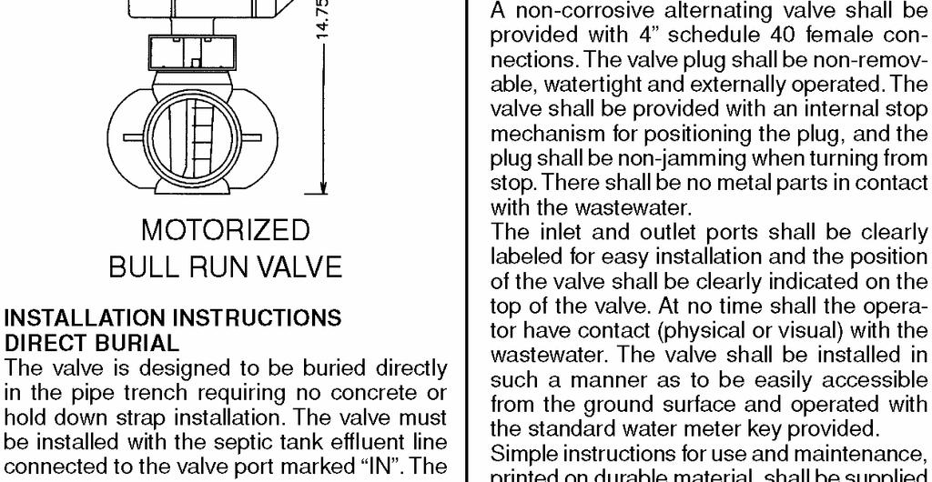
 TA1 TA1 Tank Alarm w/ Float TA3 TA3 Outdoor Tank Alarm w/ Float ITEM DESCRIPTION BRV4 Bull Run Valve 4 BRVBULK Bull Run Valve & Key Only BRVCIRISER")

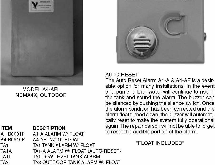
28 American Manufacturing Company, Inc. ~ Alarm Panels and Onsite Products Model # A4-AFL (w/ AO10) The Auto Reset Alarm Panels sound an alarm when water level rises due to a pump failure. The buzzer can be silenced by pushing the silence switch. Once the alarm condition has been corrected and the alarm float turned down, the buzzer will automatically reset to make the system fully operational again. ITEM MODEL DESCRIPTION A1-B0001P A1-B0013P A4-B0510P A1-A A1-AX A4-AFL Alarm Control w/ NEMA 1 Enclosure (w/ AO10 Float) Alarm (Latching) Control w/ NEMA 1 Enclosure (No Float) Alarm Control w/ NEMA 4 Enclosure, Flasher & Locking Hasp (w/ AO10 Float) TA1 TA1 Tank Alarm w/ Float TA3 TA3 Outdoor Tank Alarm w/ Float ITEM DESCRIPTION BRV4 Bull Run Valve 4 BRVBULK Bull Run Valve & Key Only BRVCIRISER Bull Run Valve Riser w/ Cast Cover BRVKEY28 Bull Run Valve Key 28 BRVKEY36 Bull Run Valve Key 36 BRVKEY48 Bull Run Valve Key 48 BRVKEY60 Bull Run Valve Key 60 Bull Run Valve The Bull Run Valve is designed to split flows to septic fields or systems. The leakproof and external operating design ensures no contact with wastewater. BRVKIT BRVMOTOR4 Bull Run Valve Kit Complete (Valve, Key 28, Plug & Adapter) Bull Run Valve Motorized Item # BRV4 Cool Guide The Cool Guide distributes the flow of effluent around a motor in a wastewater pumping application in a manner that allows motor cooling without the mixing of residual solids. ITEM COOLGUIDE15 COOLGUIDE25 COOLGUIDE40 DESCRIPTION Laminar Flow Collar 6, 15 GPM Laminar Flow Collar 8, 25 GPM Laminar Flow Collar 8, 40 GPM Item # COOLGUIDE25 ITEM DESCRIPTION Dial-A-Flow DIAL4BLACK DIAL4GRAY DIAL4GREEN Dial-A-Flow Black 4 for ADS Dial-A-Flow Gray 4 for SDR35 SCH40 & ASTM3034 Pipe Dial-A-Flow Green 4 for S&D The Dial-A-Flow is a device used to equally distribute flow out of distribution boxes. With the eccentrically located opening, the installer can rotate the Dial-A-Flow to balance all discharge ports for 7 Item # DIAL4GRAY

 or normally closed (NC) switches and various lengths, with or without plug connectors.")

29 American Manufacturing Company, Inc. ~ American Onsite Products & Accessories Item # AO10 Float Switches Float switches are utilized to signify specific liquid levels and provide an indication to the control panel. They are enclosed in durable and chemically stable polypropylene or Acrylonitrile Butadiene Styrene (ABS). They are available with pump duty or control duty amp ratings, normally open (NO) or normally closed (NC) switches and various lengths, with or without plug connectors. ITEM DESCRIPTION PO15 MECHNA Float, Pilot Duty, Mechanical, Normally Open, Narrow Angle 15 PO15 MECHNAW Float, Pilot Duty, Mechanical, Normally Open, Narrow Angle 15, Weight DHO15 Float, Pump Duty, Mechanical, Normally Open, ABS, 15A, 15 DHO15P1 DO15P1 DO15P2 Float, Pump Duty, Mechanical, Normally Open, ABS, 15A, 15, 110V Plug Float, Pump Duty, Mechanical, Normally Open, ABS, 13A, 15, 110V Plug Float, Pump Duty, Mechanical, Normally Open, ABS, 13A, 15, 230V Plug DO30 Float, Pump Duty, Mechanical, Normally Open, ABS, 13A, 30 DO30P1 Float, Pump Duty, Mechanical, Normally Open, ABS, 13A, 30, 110V Plug DC15 Float, Pump Duty, Mechanical, Normally Closed, ABS, 13A, 15 DC15P1 DC15P2 Float, Pump Duty, Mechanical, Normally Closed, ABS, 13A, 15, 110V Plug Float, Pump Duty, Mechanical, Normally Closed, ABS, 13A, 15, 230V Plug PO15 Float, Pilot Duty, Mercury, Normally Open, Polypropylene, 10A, 15 PO15W Float, Pilot Duty, Mercury, Normally Open, Polypropylene, 10A, 15, Weight PO20 Float, Pilot Duty, Mercury, Normally Open, Polypropylene, 10A, 20 PO20W Float, Pilot Duty, Mercury, Normally Open, Polypropylene, 10A, 20, Weight PO30 Float, Pilot Duty, Mercury, Normally Open, Polypropylene, 10A, 30 DC30 Float, Pump Duty, Mercury, Normally Closed, Polypropylene, 13A, 30 DC30P1 Float, Pump Duty, Mercury, Normally Closed, ABS, 13A, 30, 110V Plug Float Accessories Float bars, pipe clamps and weights for float switch applications. ITEM FLOATBAR FLOATBAR3 SWITCHBARVERT2 SWITCHBARVERT3 SWITCHBARVERT4 SWITCHCLAMP DESCRIPTION 4 Float Stainless Steel Float Bar 3 Float Stainless Steel Float Bar Float Bar 2 w/ (2) DO15 Floats Float Bar 3 w/ (3) DO15 Floats Float Bar 4 w/ (4) DO15 Floats Float Wire Pipe Clamp (Stainless Steel) Item # SWITCHBARDRIP4 Item # SWITCHCLAMP WH 8 Float Weight (Half Only)
30 American Manufacturing Company, Inc. ~ Control Panel Model Selection Guide This catalog lists American s Standard Control Panel offerings. The next two pages explain the product numbering system. For non-standard panel offerings, assemble a model number using the following tables and call American for price and delivery information at CONTROL SERIES A-ALARM OPTION B-BREAKER OPTION ENCLOSURE TYPE CONTROL PANEL OPTIONS Control Series: S Simplex SEQ Simplex Equalization D Duplex SEPR Simplex Equalization RCT (w/ PLC) T Triplex SEPT Simplex Equalization TOD (w/ PLC) Q Quadplex DEPR Duplex Equalization RCT (w/ PLC) M Multiplex (five or more) DEPT Duplex Equalization TOD (w/ PLC) MET Multiplex Equalization TOD MT Multiplex Timed Dose On Demand - CSEPR Combination Simplex Equalization RCT (w/ PLC) CSEPT Combination Simplex Equalization TOD (w/ PLC) RCT = Repeat Cycle Timer TOD = Time Of Day Timer PLC = Programmable Logic Control Alarm Option: (A) Indicator Light & Buzzer On Indoor Units, Red Lexan Top Mounted Light & Buzzer On Outdoor Units Breaker Option: Place B for Breaker in designated space followed by the desired phase and voltage code. PHASE: 1 Single phase 3 Three phase VOLTAGE: 1 120V 2 240V 4 460V 8 208v On 3 phase systems, motor protectors are substituted for breakers and require a "P" instead of the "B". If fusible disconnects for pumps are desired in place of pump breakers then replace the "P" with an "F", followed by the desired phase and voltage. Enclosure Option: 1 NEMA 1 2 NEMA 12 3 NEMA 3R 4 NEMA 4X 4S NEMA 4 (steel) 4SS NEMA 4X (stainless steel) 7 NEMA 7 (explosion proof) 9
31 American Manufacturing Company, Inc. ~ Standard Options List * A Auto Reset Alarm Circuit P(C) Pump Fail Circuit By Current Sensor B Bell/Horn (4" weatherproof) P(F) Pump Fail Circuit By Flow Switch * C Cycle Counter Q Quick Disconnect Operator D Delayed Lag Pump Timer * R Redundant Off Float Switch * E Elapsed Time Meter R(A) Redundant Off With Alarm * F Flasher S Seal Fail Indicator F(L) Flashing Light S(R) Seal Fail Relay W/ Indicator F(S) Flashing Strobe Light S(A) Seal Fail Relay W/ Alarm F(C) Flashing Light W/ Protective Cage T Thermal Cut-out G Gell Cell Battery T(I) Thermal Cut-out W/ Indicator H Hinged Inner Door T(A) Thermal Cut-out W/ Alarm I(5) Intrinsically Safe Float Switch Relays (508) U Utility Receptacle I(9) Intrinsically Safe Float Switch Relays (913) U(G) Utility Receptacle (GFI) * J Contactor/Breaker Upgrade U(W) Utility Receptacle (Weatherproof) K External Capacitor Installation V Voltage Monitor L Locking Hasp V(P) Voltage/Phase Monitor L(1) Lightning Arrestor 1 Wire W/ Gnd W Weather Heater L(2) Lightning Arrestor 2 Wire W/ Gnd W(1) Weather Heater W/ Blower (100W) L(3) Lightning Arrestor 3 Wire W/ Gnd W(2) Weather Heater (200W) L(4) Lightning Arrestor 3 Wire W/ Gnd (460) X Extra Options M Main Breaker/Disconnect Y 24 Volt Float Switch Circuit N Nema Rated Starter Z Oil tight Lights & Switches O Override Switch For Alternator * Standard Options Other options are available. For a complete description of all options, see specifications. Any option not listed above requires an X at the end of the model number and the appropriate description. EXTRA OPTIONS: A list of standard additional options provided by American Onsite Controls, but any user-selected option is also available. 1. Overload Reset Buttons (22mm) Through Door Volt Solenoid Circuit 2. Float Switch Indicator Lights 12. Ball Valve Actuator Circuit 3. Plexiglas Enclosure Window 13. Sand Filter High Level 4. Branch Power Circuit 14. Telephone Dialer Installation 5. Manual Emergency Transfer Switch 15. Drip Shield Kit 6. Generator Receptacle/Plug 16. Floor Stand Kit 7. Electrode Level Control 17. Transformer Upgrade 8. Aerator Fail Circuit 18. Circuit Breaker Padlock Hour Clock Timer 19. Full Frame Breakers 10. Pump Run Timer 20. Power Fail Circuit 10

32 American Manufacturing Company, Inc. ~ P.O. Box 97 Elkwood, VA 22718


33 AMERICAN ONSITE PRODUCTS Patent No. 4,298,470 Patent No. 6,261,452 B1 Patent No. 4,822,485 Patent No. 5,200,


34 AMERICAN ONSITE PRODUCTS 2-2

35 AMERICAN ONSITE PRODUCTS 2-3

36 AMERICAN ONSITE PRODUCTS 2-4

37 AMERICAN ONSITE PRODUCTS 2-5

38 AMERICAN ONSITE PRODUCTS Patent No. 6,61,452 B

39 AMERICAN ONSITE PRODUCTS 2-7


40 AMERICAN ONSITE PRODUCTS 2-8

41 AMERICAN ONSITE PRODUCTS 2-9

42 AMERICAN ONSITE PRODUCTS

43 AMERICAN ONSITE PRODUCTS
44 AMERICAN ONSITE PRODUCTS

45 AMERICAN ONSITE PRODUCTS

46 AMERICAN ONSITE PRODUCTS

47 AMERICAN ONSITE PRODUCTS


48 AMERICAN ONSITE PRODUCTS

49 AMERICAN ONSITE PRODUCTS

50 AMERICAN ONSITE PRODUCTS

51 AMERICAN ONSITE PRODUCTS

52 AMERICAN ONSITE PRODUCTS

53 AMERICAN ONSITE PRODUCTS

54 AMERICAN ONSITE PRODUCTS

55 American manufacturing Company, Inc. PERC-RITE Drip Dispersal Filtration Systems Featuring: Automatic Timed Dosing Automatic Field Flushing Manual, Semi-Automatic or Automatic Filter Cleaning Uses Disc Filters for Low Maintenance No High Maintenance Screens!! The PERC-RITE Drip System is a complete wastewater dispersal system utilizing pressure compensating drip tubing, automatic disc filtration, automatic forward field flushing and efficient effluent pumps with state-ofthe-art controls for long term sustainable onsite wastewater installations Use Filters! Not Screens! A Filter that has both surface area and depth can be cleaned through automatic backwashing. Particle separator Filters of this design can last for years before maintenance. Even neglected filters will continue to protect the tubing and field. A Screen particle separator only has surface area and cannot be cleaned through backwash. Screens cannot be cleaned in placed but must be removed and cleaned or replaced. Dirty Screens may collapse and can extrude material which may damage tubing and cause field failure.


56 American Manufacturing Company, Inc. s PERC-RITE Filtration system offers several choices of filtration, based on your budget and the desired intervals between Service Events Manual Cleaned Filters Manually cleaned Disc Filters efficiently and economically clean secondary treated effluent, with service frequency based on water quality, usage and the size of the Filter Wash Down Filters Wash Down Filter Systems automatically remove contaminates from the surface of the filter, substantially increasing the time between manual service events in a secondary effluent dispersal system In a secondary treated effluent application, filter backwash water is cleaned through a large manual cleaned filter prior to back washing the field dosing filter. This configuration creates a very economical controller to manage the system with maintenance frequencies being extended for up to a year. Reduced pretreatment water quality will increase the maintenance frequency requirements, however any potential filter buildup will result a high water alarm, protecting the system from catastrophic failure Semi-Automatic Filters Fully Automatic Filters For Septic or Secondary Effluent Quality Water! Fully automatic systems are self maintaining and can go years without servicing. Filters are fully cleaned at the beginning and during each dose cycle. The backwash regime is adjustable to deal with a full range of water quality, from septic to advanced secondary. Annual system inspections are still recommended just like we recommend for all conventional systems. ALL LARGE FLOW SYSTEMS ARE REC- OMMENDED TO BE FULLY AUTOMATIC! American Manufacturing Company, Inc., P.O. Box 97, Elkwood, VA Tel, Fax,
57 AMERICAN ONSITE PRODUCTS American COOLGUIDE 3-1
58 AMERICAN ONSITE PRODUCTS PERC-RITE DRIP PUMPS 3-2

59 AMERICAN ONSITE PRODUCTS BIOLINE DRIP TUBING 3-3

60 AMERICAN ONSITE PRODUCTS BIOLINE TECHNICAL SPECIFICATIONS 3-4
 www.americanonsite.")
61 AMERICAN ONSITE PRODUCTS BIOLINE TECHNICAL SPECIFICATIONS (CONT.) 3-5
62 AMERICAN ONSITE PRODUCTS BIOLINE FITTINGS 3-6

63 AMERICAN ONSITE PRODUCTS AIR VENTS 3-7

64 AMERICAN ONSITE PRODUCTS AIR VENT SPECIFICATIONS 3-8

65 AMERICAN ONSITE PRODUCTS DISC FILTERS 3-9

66 AMERICAN ONSITE PRODUCTS DISC FILTER TECHNICAL SPECIFICATIONS

67
68
69
70


71 INNOVATIVE TECHNOLOGY FOR THE ENVIRONMENTAL AGE ~ Buy American ~ Perc-Rite Drip Systems Protecting the Future of America American Manufacturing Company, Inc. P.O. Box 97 Elkwood, VA 22718

72 Why Drip Dispersal? Drip Dispersal is a land application system for dispersal of wastewater effluent in decentralized environments. Drip utilizes time dosed, low volume, equally distributed doses over an entire absorption area while at the same time providing final treatment and recycle back into the environment. Drip provides optimum conditions for groundwater recharge to the receiving environment. It is ideal for any size system: single family homes, schools, churches, state parks, communities, commercial sites, etc. Drip systems are aesthetically pleasing and are installed subsurface utilizing the out-of-site, out-of-mind theory. Drip fields lend themselves to passive recreation with year round natural irrigation. Time dosed systems provide for managing rest times between doses, peak flow notification, excess flow alarms and helps prevent soil saturation by maintaining an aerobic environment at the tubing interface. Drip is ideal for shallow installations, which maximizes the standoff to any site restrictions (i.e. rock, seasonal water table, etc.). Sloping sites and/or wooded sites are not a problem. Drip Dispersal is utilized in both warm and cold climates 365 days per year! Drip can reduce storage requirements and may offer a reduced area footprint compared to conventional systems. Drip is a reliable, proven and permanent option for your wastewater dispersal needs. Why Perc-Rite Drip? The original drip technology! The world-renowned Perc-Rite technology was the first drip dispersal system developed for use in wastewater applications. The Perc-Rite Drip System is a complete wastewater dispersal system utilizing pressure compensating drip tubing, automatic disc filtration, automatic periodic forward field flushing and efficient effluent pumps with totalizing flow meter and state-of-the-art controls plus design standards for long term sustainable onsite wastewater installations. The pressure compensating drip tubing allows for complete equal distribution of the effluent. Disc filtration provides the necessary protection for the drip emitters prior to the drip field. The disc filters automatically backwash at preset intervals. The Perc-Rite Drip System also automatically forward flushes the drip tubing ona periodic basis at the generally accepted engineering standard for minimum scouring velocity of 2.0 ft/sec. The Perc-Rite System sets the standard for excellence in drip technology! How much Pretreatment is required? Primary settling is all that is required for the Perc-Rite Drip technology. Drip dispersal is dependent on the soils and receiving environment, so specific site restrictions may dictate the quality and extent of any additional pretreatment that is required. Why American Manufacturing? With over 1 billion emitters installed in subsurface wastewater applications, Perc-Rite is the largest Drip System name in North America. With American s in-house control panel fabrication we offer a single source complete Perc- Rite Drip Dispersal System. We have over 100 years combined experience in the wastewater industry. Our technical support is first class and is unmatched. American continues to offer ongoing technical service even after the sale. All wastewater systems require long-term operation and maintenance, so American Manufacturing provides complete O & M manuals for both owners and installers. All of our drips system models are available with Remote Operation and Monitoring capabilities and long-term call in tech support. We are an engineeringdriven company staffed with Professional Engineers, Soil Scientists and designers to keep us a leader on the cutting edge of technology. We strive to provide our customers with proven, durable, and dependable complete systems to satisfy even the toughest onsite needs. American Perc-Rite truly is the finest Drip Dispersal System available.
73 A M E R I C A N PERC-RITE WASTEWATER DRIP DISPERSAL SYSTEMS DESIGNERS GUIDE Use With Approved Netafim Tubings PATENT NO. 5,200,065 Innovative Technology for the Environmental Age PATENT NO. 5, B American Manufacturing Company, Inc P.O. Box 549 Manassas, Virginia Copyright
74 AMERICAN Manufacturing Company, Inc.
75 DESIGNERS GUIDE AMERICAN PERC-RITE WASTEWATER DRIP SYSTEMS 2 ZONE or 4 ZONE SIMPLEX or DUPLEX PATENT NO. 5,200,065 and 5,984,574B CONTENTS Page SYSTEM LAYOUT 2 SYSTEM COMPONENTS 3 DESIGN PROCEDURES 4 DESIGNERS WORKSHEET 5 AREA DELINEATION 6 LOADING RATE TABLE 7 ZONE DETAIL NUMBERING SYSTEM 8 INSTALLATION INSTRUCTIONS 9 15 GPM ZONE DETAIL TABLE GPM ZONE DETAIL TABLE 12 RUN TIME TABLES 14 HYDRAULIC PROFILE 16 OPERATION AND MONITORING 19 SYSTEM PACKAGE DETAILS 20 ELECTRICAL AND OPERATIONAL SPECIFICATIONS 22 SUBMITTAL INSTRUCTIONS 23 WARRANTY 24 INTRODUCTION This Perc-Rite Drip System Designers Guide is for the non-engineer designer. Procedures have been developed to size, layout and design a Perc-Rite Drip system using tables instead of performing extensive calculations. The tables have conditions which allow the designer considerable flexibility to layout systems in a variety of siting conditions without being required to do detailed engineering calculations to determine design suitability. When advanced system design is required, outside the limitations of this design procedure, the designer may reference the design manual located on our web site and complete a detailed calculation sheet to determine suitability. Reference The Perc-Rite Drip System is a unique fluid handling system for dispersal of effluent wastewater in soil systems. The system incorporates filtration, time and level controlled application and ultra low rate drip distribution. In conditions where aerobic dispersal, such as Low Pressure Distribution, of septic effluent is required or where land application with the use of conventional soil absorption fields are not acceptable, this system offers a unique method for subsurface distribution of the waste water effluent. State regulations require varying effluent treatment quality for onsite systems. Preconditioning Treatment requirements for Perc-Rite Drip Systems are minimum. The process will accommodate virtually any type of pretreatment process, aerobic, lagoon, or any type of approved treatment facility. The removal of large settleable solids in sewage is necessary for the successful operation of the system. Local soil and site conditions may require additional treatment for excessive organics, oil and grease or other contaminants. Page No. 1 Copyright 2006
76 There is virtually No Site Disturbance during installation of the field distribution lines. Typical vibratory plow installation causes very little soil disturbance. The effluent discharge volume from each emitter hole is very small. The system has little site impact even in established lawns or park areas. After installation there are no visible indications that the installation site is being used for disposal. The system is especially suited for landscaped or wooded areas near buildings, trailer parks, apartment complexes or residential subdivisions. TYPICAL LAYOUT AMERICAN Manufacturing Company, Inc. Perc Rite Drip Dispersal Pat. # 5,984,574B Pat. # 5,200,065 Copyright 2006 Page No. 2
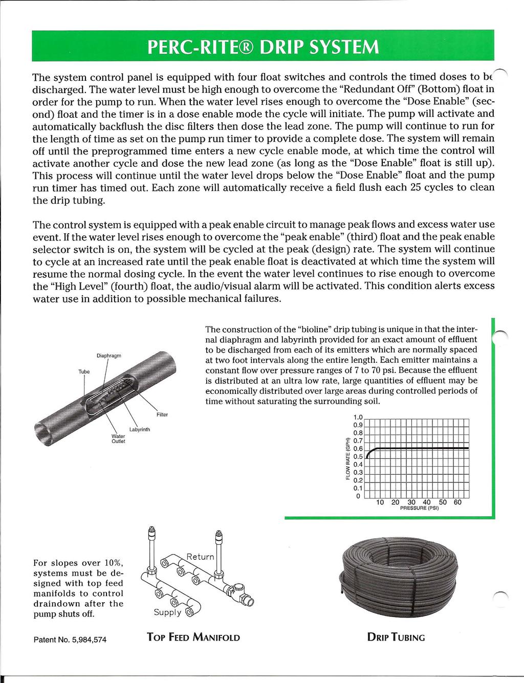
77 SYSTEM COMPONENTS 1. The PERC-RITE DRIP SYSTEM CONTROLLER is a state of the art control panel, activated by level sensing devices (standard mechanical differential float switches) located in a dosing tank downstream from the pretreatment process or processes. When activated by the rising level of effluent in the dosing tank, the controller will enable the dose or dispersal. The system controller on a time clock basis will pump the effluent through the filter module and then to final drip dispersal. 2. FILTER MODULE - Disc filters, automatic control valves, solenoid activated diaphragm valves, and a flow meter are assembled in a enclosure (with optional heating) and provided with a labeled wire harness for easy connection to the control panel. 3. PUMP SYSTEM - The pump, Cool Guide and float switches for level indication are provided for installation into the pump tank. The pump is a 15 gpm turbine pump and will be suitable for most residential installations. Reference lift and distance table for pumping limits. 4. DRIPPER TUBING - The dripper tubing is pressure compensating dripperline for wastewater. The tubing delivers a nominal 0.65 gallons per hour (+/- 5% flow rate from 7 to 60 psi). The tubing functions as a turbulent flow emitter between 0 and 7 psi, ensuring that the nominal design flow is not exceeded at system start-up. The tubing is polyethylene with a 120 psi pressure rating. 5. TOP FEED MANIFOLD SYSTEM - The Top Feed Manifolds are located at the highest point in the drip zone and are provided with air release valves to prevent drain down of upper laterals in the zone to lower laterals in the zone, thus preventing saturation of the lower laterals after the pump shuts off. The system provides for the fastest possible pressurization of the zone and the most efficient method of providing drain down control. If the site is flat, Top Feed Manifolds may not be required. Patent No. 5,984,574B. 6. DRIP FIELD MATERIALS - All special drip fittings and equipment are supplied by American Manufacturing Company, Inc., including the tubing insert fittings, connectors, flex tube and non- schedule 40 PVC standard fittings. 7. STANDARD FIELD MATERIALS - All tanks, wire, standard pipe and fittings are provided by the contractor at the local site. The 1 supply and return pipes, the 1/2 pipe for installation between the top feed manifold system and the laterals and other miscellaneous PVC pipe are to be purchased locally. Page No. 3 Copyright 2006
78 DESIGN PROCEDURES 1. DEMAND ANALYSIS - Local codes determine the amount of wastewater to design for. Many codes have a safety factor or peak flow factor in the prescribed design flow. Others are based on more of an average usage. In either event, the designer must determine what the peak (design) flow is. The Perc-Rite Drip System will disperse the average flow through out each day unless the Peak float is enabled, at which time the system will disperse effluent at an accelerated design daily flow rate. Record the number of bedrooms and the peak design flow on line 3 of the worksheet. 2. SITE AND SOILS EVALUATION - Soil and site evaluation is required according to state and local criteria (see page 7). The design loading rate shall be expressed as the area and the linear feet of tubing required. The delineated area for installation, effluent quality and the installation depth need to be determined. Long and narrow runs along contour are best. The professional judgement of the evaluator and designer should be used in applying the regulation to determine the wastewater application rate for any specific site. Record the determined soil type on line 2 and selected loading rate area on line 7 of the worksheet. 3. DELINEATE AREA - On a site plan or a site sketch, the designer should lay out the area of installation on contour. The width along contour should be determined and this distance will determine the necessary down slope distance in order to allocate sufficient total area. The distance down slope will dictate the number of runs which can be installed in the dispersal site. Make sure enough runs can be installed for the total wastewater capacity and the amount of tubing required. Site conditions determine the run separation. Runs can vary from 1 to 3 feet of separation but are more frequently from 1-1/2 to 2 feet on center. The total linear feet of tubing required is recorded on line SELECT ZONE DETAIL - Once the area and total tubing length is determined, enter the contour run length in worksheet line 4. A standard zone detail is selected based on the width across contour and the total tubing length. Make sure the needed number of runs can be installed in the delineated area (see Zone Detail Table). Record the selected zone detail on line 11. If there is not a zone detail with the exact run length, select a zone detail from the column with the next larger run length. Determine the minimum number of runs and record in line 10b. Select the zone detail with the same or more number of runs. For Example, let s say a zone detail using a 15 GPM Standard Zone Detail Table that has 85 runs needs 1800 LF at 2 OC. The minimum runs = 22 (1800 LF tubing / 85 contour RL = 21.17, rounded up to 22 runs). Since there is no system available for 22, scroll down to 24 and record in line 10b under Spec. (Specified) # runs. The zone detail is a Z243 and the installed spacing between runs will be 1.75 OC. The total linear feet is the number of runs for the selected zone detail times line 4. Record the total linear feet per zone provided on line 13. See the Zone Detail Table (either septic and secondary or secondary only). Also, see the Dosing & FF Flow Table. 5. LAYOUT SITE - On a site plan or site sketch show the route for the supply and return pipes. Show the distance the supply and return pipes travel. On a site plan or site sketch show the location of the tanks, filter module and the control panel. Determine the length of supply line run and record on line 5. Determine the lift to the field and record on line DETERMINE SUITABILITY - Reference the Lift and Distance Table (page 11 or 13) and show the maximum lift on line 12 (page 5). Using the pipe length to the farthest field (Supply/Return Line column) and the number of laterals, record the maximum static lift suitable for the 1 supply and return pipe on line 6. If the maximum lift on line 12 is greater than the lift recorded in line 6, check Yes in line 15 of the worksheet; otherwise, check No. Copyright 2006 Page No. 4
79 PERC-RITE WORKSHEET - Dispersal system design worksheet for residential systems. 1 Y N ( ) ( ) Are supply and return pipes 1? ( ) ( ) Is the lift to the HU <8 and the run to the HU <30 with 1-1/2 pipe? Septic ( ) or Secondary ( )? Anaerobic ( ) Effluent Quality Aerobic ( ) 2 Soil Texture/ Structure Found in column 1 on the Loading Rate Chart (page 7). 3a GPD 3b # Bedrooms 4 Contour Run Length Design quantity of wastewater to disperse. (150 GPD per bedroom) Enter the tubing run length. If run length is not on table, use the actual run length. Example:85 ft. 5 Supply LF Length of supply line between hydraulic unit and farthest zone. 6 Lift ft. Vertical lift from off level in the pump chamber and highest zone elevation Area (gal/ ft2/day) per code Min. Area Calculation Total LF Tubing 10a Calculated Runs Area loading rate required to treat and disperse wastewater. (See Loading Rate Chart) Total land area needed to disperse wastewater. (line 3a / line 7) Required total linear feet of tubing to treat and disperse wastewater. (line 8 / 2) Number of runs (line 9 / line 4). 10b Min. # Runs Round up to next whole number to determine Min. # Runs. Reference Zone Detail Table. 11 Zone Detail Select zone detail from column with next higher Contour Run Length (line 4) and with equal or greater # of Runs (line 10b). 12 Max. Lift Allowed 13 LF Provided Found on the Lift & Distance Table. Cross supply/return equal to line 5 with the appropriate number of laterals. Total linear feet of tubing provided to disperse wastewater. (# of zones x laterals per zone x runs per lateral x Contour Run Length) 14 LF/Zone Total linear feet of tubing per zone. (LF Provided / # of zones) 15 Will zone flush? Y N ( ) ( ) Reference Lift & Distance Table for pump capacity determined by the length of run to the farthest field and the number of laterals. For 1 supply and return only. Page No. 5 Copyright 2006
80 AREA DELINEATION A complete site evaluation includes a surface characterization of topographic features and horizontal setbacks, a subsurface (soil) evaluation, and the accurate delineation of the soil absorption area. This delineation is best performed by the site evaluator. The area should be marked and measured in the field to insure protection of the area and a representative final absorption area design. Tools required would include a measuring tape to dimension the site, stakes to delineate the area and a leveling device such as a builders level, lock level, or clinometer to determine contour. Care should be exercised to insure accuracy on sites with limited area and those that are topographically complex. It is important to minimize site skewing, account for topographic contour wrapping and verify available area. The header ditch(es) area should be as perpendicular to topographic contour as possible. AMERICAN MANUFACTURING Copyright 2006 Page No. 6
81 NATIONAL LOADING RATE CHART For AMERICAN Perc-Rite Drip Systems SOIL LOADING RATE TABLE This is based on a standard tubing spacing between runs of 2 feet on center. Therefore a typical area-loading rate would be a number that is one half the linear feet loading rate number. For example, for a 1.2 gallons/l.ft./day rate would be equivalent to 0.6 gallons/ft2/day. Spacing may be changed for specific site conditions. For example: a tubing-loading rate of 0.4 is an area load of 0.2. By placing the tubing 1 on center, the resulting area loading would be at 0.4, or 1/2 of the area. This can only be done with proper site and soil evaluation. ANAEROBIC AEROBIC Soil Textures Soil Structure Maximum Monthly Average Maximum Monthly Average BOD5 > 30mg/L BOD < 220mg/L BOD5 < 30mg/L (gal./ft2/day) (gal./lf/day) (gal./ft2/day) (gal./lf/day) Coarse sand or coarser N/A Loamy coarse sand N/A Sand N/A Loamy sand Weak to strong Loamy sand Massive Fine sand Moderate to strong Fine sand Massive or weak Loamy fine sand Moderate to strong Loamy fine sand Massive or weak Very fine sand N/A Loamy very fine sand N/A Sandy loam Moderate to strong Sandy loam Weak, weak platy Sandy loam Massive <.1 < Loam Moderate to strong Loam Weak, weak platy Loam Massive <.1 < Silt loam Moderate to strong Silt loam Weak, weak platy <.1 < Silt loam Massive Sandy clay loam Moderate to strong Clay loam Weak, weak platy <.1 < Clay loam Moderate to strong Silty clay loam Weak, weak platy <.1 < Silty clay loam Massive Silty clay loam Moderate to strong Sandy clay Moderate to strong <.1 < Sandy clay Massive to weak Clay Moderate to strong <.1 < Clay Massive to weak Silty clay Moderate to strong <.1 < Silty clay Massive to weak Site suitability, loading rate, and installation depth determination must be assigned based on thorough site/soil evaluation. The characterization of a soil based receiver site involves a systematic evaluation by trained individuals. Conditions to consider consist of a variety of topographic and soil conditions such as landscape position, slope, soil depth, depth to water table, depth to restriction, soil consistence, clay mineralogy, compaction, density, and site geometry and uniformity. Drip disposal lends itself to shallow installation. Typical depths are from 6-18, with 8-10 preferred and installations infrequent. Separation to limitations should always be maximized while maintaining a consistent depth on contour in a permeable horizon. Refer to state and local regulatory requirements for appropriate site suitability guidance. Page No. 7 Copyright 2006
82 ZONE DETAIL NUMBERING SYSTEM Each zone is designated by a Z indicating it is a Zone Detail Designation followed by three groups of numbers, the first is the number of zones, the second is the number of laterals per zone, the third is the runs per lateral. Z = Zone # Zones # Laterals # Runs/Lat EXAMPLE 1 Z Z = Zone # Zones # Laterals # Runs/Lat This example shows a one zone detail with two laterals per zone and two runs per lateral. ZONE DETAIL SELECTION PROCEDURE Reference the site plan layout to determine the width across contour of the delineated area. From the site and soils evaluation determine the total amount of tubing required. The area divided by two is the total linear feet of tubing required. The total linear feet of tubing divided by the length across contour equals the minimum number of runs. The total number of linear feet of tubing and runs will typically be more than the minimum since the preferred layout for flushing the supply and return lines will typically result in more than the minimum tubing. Increasing the number of runs in order to install a standard zone configuration is encouraged. This provides an additional safety factor to the tubing interface loading rate. Use the following step by step procedure to select a zone detail. 1. Determine width across contour. 2. Determining number of runs that can be installed in area. 3. Select a standard zone detail from under the column for contour with which has enough tubing to satisfy total tubing requirements. 4. In the event more runs are needed to yield enough tubing for the site, the tubing may be placed closer than 2 on center. EXAMPLE 2 (Using 12gpm Semi Automatic Zone Detail Table on Page 12) This configure does not work for the ASD 15 Contour width = 100 Feet Tubing required = 700 Linear Feet From the table, the linear feet of tubing provided in 100 foot runs will be between 600 LF and 800 LF. Therefore select 8 runs for 800 LF. The zone detail could be; Z Z = Zone # Zones # Laterals # Runs/Lat Copyright 2006 Page No. 8
83 INSTALLATION INSTRUCTIONS 1. Prepare field location for installation. Verify contour and design. No wet weather installation. No activity on drainfield other than minimum to install system. Clearing of vegetation to be performed with minimal site disturbance. Do not park equipment or store materials on drainfield area. 2. Set pretreatment and pump tanks. 3. Dig header ditch for field manifold. 4. Install dripper tubing. Horizontal spacing between dripper lines shall be as specified and installation depth shall be as specified. Install on contour. 5. Install loops (flex tubing) and construct field supply / return manifolds. All PVC pipe and fittings shall be PVC SCH 40 type 1 rated for pressure applications. All glued joints shall be cleaned and primed with purple (dyed) PVC primer prior to being glued. All cutting of PVC pipe, flexible PVC and/or dripper tubing shall be accomplished with pipe cutters. Sawing of PVC pipe, flexible PVC and/or dripper tubing shall be followed by cleaning all shavings or sawing shall not be allowed. All open PVC pipe, flexible PVC and/or dripper tubing in the work area shall have the ends covered with duct tape during construction to prevent construction debris from entering the pipe. Prior to gluing all glue joints shall be inspected for and cleared of construction debris. 6. Dig ditches for conveyance lines, pump supply line, and flush return line. Install. Connect supply / return lines with manifolds. 7. Place Central Unit and mount control panel. Connect conveyance, supply, and flush return lines to hydraulic unit. 8. Set switch tree in pump tank. 9. Install electrical (and phone line if applicable). Check power supply and power up unit. 10. Provide one day volume of clean water for startup. Prior to startup of the drip disposal system the air release valves shall be removed and each zone in the system shall be flushed as follows: a) using an appropriate length of flexible PVC pipe with a male fitting attached to the air release connection to direct the flushing away from the construction are, b) flush the zone with a volume of water (clean water to be provided by contractor) equal to 1.5 times the volume of the pipes from the central unit to the air release valve, c) repeat this procedure for each zone (the flushing of the system is accomplished by manual override of the control panel by the manufacturer or engineer.) Once completed replace and glue air relief valves. If existing septic tanks are to be used, they shall be pumped out by a commercial septic tank pumper, checked for leakage or other problems, and replaced if necessary. After the tank is emptied, the tank shall be rinsed, pumped, and refilled with clean water. Debris in septic tank shall be kept to a minimum since it could clog the disk filters during startup. (Disk filters are not backflushed during startup and any clogging could cause incorrect rate of flow readings for the controller.) 11. Pressure check all fittings and lines. Inspect field and loops. Find leaks and repair. 12. Check setup values against calculated values. Set run time for Central Unit. 13. Backfill once lines and fields are determined to have no leaks. Back filling is to be controlled to prevent the damaging of pipes or fittings. Once completed, drainfield area should be graded to shed surface water with additional clean soil as necessary. Establish fescue or other turf cover, cut long (6-8 ). 14. In cold weather climates, installer should follow all cold weather installation techniques. Refer to local standards. Page No. 9 Copyright 2006
84 Length Across Contour RUN LENGTH #RUN ZD LF ZD LF ZD LF ZD LF ZD LF ZD LF ZD LF ZD LF ZD LF 4 Z GPM AUTOMATIC PERC-RITE DRIP SYSTEMS: ASD SERIES - SEPTIC OR SECONDARY EFFLUENT STANDARD ZONE DETAIL TABLE 6 Z Z Z Z Z Z Z Z Z Z Z Z Z Z Z Z Z Z Z Z Z Z Z Z Z Z Z Z Z Z Z Z Z Z Z Z Z Z Z Z Z Z Z Z Z Z Z Z Z Z Z Z Z Z Z Z Z Z Z Z Z Z Z Z Z Z Z Z Z Z Z Z Z Z Z Z Z Z Z Z Z Z Z Z Z Z Z Z Z Z Z Z Z Z Z Z Z Z DOSING & FF FLOW TABLE (GPM) 15 GPM AUTOMATIC DRIP SYSTEMS: 24 EMITTER SPACING AMERICAN GPM FF FF FF FF FF FF LF/ DOSE NO. NO. NO. NO. NO. NO. ZONE RATE LATS LATS LATS LATS LATS LATS Copyright 2006 Page No. 10
85 PERC-RITE LIFT AND DISTANCE TABLE 15 GPM AUTOMATIC DRIP SYSTEMS: 24 EMITTER SPACING LIFT & DISTANCE TABLE INSTRUCTIONS 1. The vertical lift is the elevation difference between the Off Level Float and the highest point in any drip zone. 2. The supply/return line column is the distance from the filter to the farthest drip zone. 3. The diameter of the pipe from the pump tank to the filter unit is 1-1/2 minimum. 4. All zone supply and return pipes are The flush return pipe from the filter box to the pretreatment tank is 1-1/2 gravity. 6. The maximum distance from the pump tank to the filter valve box is 30 and the vertical lift from the pump chamber to the filter valve box is These tables may be used with the appropriate Perc-Rite zone detail table only. An engineering calculation sheet (not included herein) must be filled out for any other configuration. 8. Top feed manifolds must be used when any discernible slope is encountered. 9. Remote zone valves are needed when pumping downhill from the filter. For aid in this aplication call American Manufacturing. 10. Return pressure assembly is needed when lift from filters to zones is greater than 10. LIFT AND DISTANCE TABLE 15 GPM AUTOMATIC DRIP SYSTEMS: 24 EMITTER SPACING Maximum Static Lift ( Off Level Float to Drip Field) Supply/ 1 Return Line 2-Lat 3-Lat 4-Lat 5-Lat 6-Lat 7-Lat (feet) Page No. 11 Copyright 2006
86 12 GPM SEMI-AUTOMATIC PERC-RITE DRIP SYSTEMS: QUALITY MONITORING QM SERIES - SECONDARY EFFLUENT STANDARD ZONE DETAIL TABLE AMERICAN Length Across Contour RUN LENGTH # RUNS ZD LF ZD LF ZD LF ZD LF ZD LF ZD LF ZD LF ZD LF ZD LF 2 Z Z Z Z Z Z Z Z Z Z122 Z141 5 Z Z Z Z123 Z Z124 Z Z124 Z Z123 Z132 Z142 Z222 Z Z122 Z Z122 Z141 Z Z132 Z231 9 Z Z Z Z Z Z Z Z125 Z Z126 Z134 Z Z135 Z Z144 Z224 Z Z136 Z Z145 Z225 Z Z226 Z234 Z Z235 Z Z134 Z143 Z223 Z232 Z224 Z Z223 Z Z Z Z Z234 Z Z142 Z222 Z Z Z Z222 Z Z Z Z Z Z s\data\salesmarket\saleslit\catalog\literature\zonetable. c:\data\msword\manual\zonetable-qm-master Z141 Z Z141 Z Z141 Z Z Z Z Z Z Z Z Z DOSING & FF FLOW TABLE (GPM) 12 GPM SEMI-AUTOMATIC DRIP SYSTEMS: 24 EMITTER SPACING GPM FF FF FF FF LF/ZONE DOSE RATE NO. LATS. NO. LATS. NO. LATS. NO. LATS Copyright 2006 Page No. 12
87 PERC-RITE LIFT AND DISTANCE TABLE 12 GPM SEMI-AUTOMATIC DRIP SYSTEMS: 24 EMITTER SPACING LIFT & DISTANCE TABLE INSTRUCTIONS 1. The vertical lift is the elevation difference between the Off Level Float and the highest point in any drip zone. 2. The supply/return line column is the distance from the filter to the farthest drip zone. 3. The diameter of the pipe from the pump tank to the filter unit is 1-1/2 minimum. 4. All zone supply and return pipes are The flush return pipe from the filter box to the pretreatment tank is 1-1/2 gravity. 6. The maximum distance from the pump tank to the filter valve box is 30 and the vertical lift from the pump chamber to the filter valve box is These tables may be used with the appropriate Perc-Rite zone detail table only. An engineering calculation sheet (not included herein) must be filled out for any other configuration. 8. Top feed manifolds must be used when any discernible slope is encountered. 9. Remote zone valves are needed when pumping downhill from the filter. For aid in this aplication call American Manufacturing. 10. Return pressure assembly is needed when lift from filters to zones is greater than 10. LIFT AND DISTANCE TABLE 12 GPM SEMI-AUTOMATIC PERC-RITE DRIP SYSTEMS: 24 EMITTER SPACING Maximum Static Lift ( Off Level Float to Drip Field) Table A: STANDARD 12 GPM QM LIFT & DISTANCE TABLE Supply/ 1 Return Line 2-Lat 3-Lat 4-Lat 5-Lat (feet) Note: Use Table B when using Hydro Seq Valve Table B: 12 GPM QM w/ HYDRO SEQ DISTRIBUTING VALVE Supply/ 1 Return Line 2-Lat 3-Lat 4-Lat 5-Lat (feet) Note: Use this table when using Hydro Seq Valve Page No. 13 Copyright 2006
88 RUN TIME TABLES: 15 GPM AUTOMATIC PERC-RITE DRIP SYSTEMS The run time tables are based on the gallons per day the system is designed for. The run time numbers are based on the average daily flow rate. Selecting the run time is the last design step that is performed. Based on the number of zones and the number of laterals per zone, the run time is selected based on the average gallons per day. For even distribution and minimizing draindown events, the run time is calculated to provide from 3 to 5 times the volume of drip tubing plus the top feed manifolds. Therefore, the number of doses per day per zone will vary in order to maintain optimum dispersal. American Manufacturing 2-Zone 3-Zone 4-Zone Laterals/Zone: 2-Lat 3-Lat 4-Lat 5-Lat 6-Lat 7-Lat 2-Lat 3-Lat 4-Lat 5-Lat 6-Lat 7-Lat 2-Lat 3-Lat 4-Lat 5-Lat 6-Lat 7-Lat Lateral Length: Design Avg GPD GPD Min/ Min/ Min/ Min/ Min/ Min/ Min/ Min/ Min/ Min/ Min/ Min/ Min/ Min/ Min/ Min/ Min/ Min/ Dose Dose Dose Dose Dose Dose Dose Dose Dose Dose Dose Dose Dose Dose Dose Dose Dose Dose Total LF in STANDARD & PEAK REST TIMES TO BE SET AT SYSTEM START-UP 2 ZONE 3 ZONES 4 ZONES Rest Time Rest Time Rest Time Standard Peak Standard Peak Standard Peak (min) (min) (min) (min) (min) (min) 4 Doses/day/zone Doses/day/zone AMERICAN Doses/day/zone Doses/day/zone Copyright 2006 Page No. 14
89 RUN TIME TABLES: 12 GPM SEMI-AUTOMATIC PERC-RITE DRIP SYSTEMS The run time tables are calculated for achieving the best distribution of the average daily flow in gallons per day the system is designed for. Selecting the run time is the last design step that is performed and is based on the number of zones and the number of laterals per zone. The run time should result in even distribution and minimizing draindown events. The run time is calculated to provide from 3 to 7 times the volume of drip tubing plus the top feed manifolds. Therefore, the number of doses per day per zone will vary in order to maintain optimum dispersal. AMERICAN MANUFACTURING - QM SERIES 1-ZONE AMERICAN MANUFACTURING - QM SERIES 2-ZONE Laterals/Zone: 2-Lat 3-Lat 4-Lat 5-Lat Laterals/Zone: 2-Lat 3-Lat 4-Lat 5-Lat Lateral Length: Lateral Length: Design Avg. GPM: Design Avg. GPM: GPD GPD Min./dose Min./dose Min./dose Min./dose GPD GPD Min./Dose Min./dose Min./dose Min./dose TOTAL L.F. IN ZONE= TOTAL L.F. IN ZONE= STANDARD & PEAK REST TIMES TO BE SET AT SYSTEM START-UP ONE ZONE LEGEND: REST TIMES TWO ZONE LEGEND: REST TIMES Standard Peak Standard Peak (min) (min) (min) (min) 4 Doses/day/zone Doses/day/zone Doses/day/zone Doses/day/zone Doses/day/zone Doses/day/zone Doses/day/zone Doses/day/zone Doses/day/zone Doses/day/zone Page No. 15 Copyright 2006
90 AMERICAN MANUFACTURING Copyright 2006 Page No. 16
91 Page No. 17 Copyright 2006
92 Copyright 2006 Page No. 18
93 OPERATION AND MONITORING FOR PERC-RITE DRIP SYSTEM The PERC-RITE DRIP SYSTEM has been developed to automatically monitor operational functions. The system is designed to be easily fixed after it breaks, in other words periodic monitoring can confirm good operating conditions but there are no maintenance procedures necessary until a mechanical component needs repair. Furthermore, any malfunction or breakage of a mechanical component will result in a failure similar to any traditional system, including a wet spot in the field, a backup or a high level alarm. The MONITORING FREQUENCY should be no more than traditional systems. The most important component for the operational success is owner awareness. All onsite systems have a finite hydraulic capacity. Drip systems have no storage capacity in the soil system so storage or flow equalization must be provided in the pump tank. The owner must be aware system exists and their limitations for usage. After a successful installation and startup the system should be inspected from one to three months after the owner takes occupancy to confirm operational compliance and to inform the owner of the operational characteristics of the system. The system should then go on a schedule of annual inspections to monitor usage and inspect system for wear in order to minimize emergency service requirements. Each system is provided with an owners manual. The local dealer has a more detailed installation and maintenance supplement manual. If more than septic pretreatment is provided, more frequent monitoring may be required. Provide monitoring frequency at the rate determined by the most sensitive component. An OPERATIONAL CHECKLIST is provided in the dealer s supplement manual for determining satisfactory operation of the system. The following topics are covered; 1. Field Conditions 2. Check septic tank and pump tank condition 3. Check operation of pump, control and valves. 4. Check zone dose rates. 5. Evaluate and record meter for usage. Page No. 19 Copyright 2006
94 15 GPM Automatic PERC-RITE DRIP SYSTEMS ASD 15 Series - Secondary Effluent ASD152-S122 2 Zone drip w/ simplex 2 filter, 2-zone control panel LINE# COMPONENT DESCRIPTION QUANTITY CENTRAL UNIT EQUIP PACKAGES 1 DH2-22KIT 2 ZONE DRIP SYSTEM KIT 1 2 DP1-B9140P SIMPLEX 2 ZONE CONTROL 1 3 PUTURB W 15 GPM TURBINE 1 4 COOLGUIDE 15 LAMINAR FLOW COLLAR, 6, 15 GPM 1 5 PUMPKITDRIP DRIP PUMP KIT 1 1/2 1 6 BIOLINE 1000 DRIP TUBING PER 1000 FT ROLLS 2 7 PVC12FLEX 1/2 FLEX PVC BIOINSERT12X34 BIOLINE INSERT ADAPTER 1/2 X 3/ PVCPRFIP12X34 FEMALE ADAPTER 12X34 SXT SCH BIOCOUP BIOLINE REPAIR COUPLING 1/ DH-TOPFEEDKIT TOP FEED MANIFOLD KIT 1 2 ASD153-S124 3 Zone drip w/ simplex 2 filter, 4-zone control panel LINE# COMPONENT DESCRIPTION QUANTITY CENTRAL UNIT EQUIP PACKAGES 1 DH2-23KIT 3 ZONE DRIP SYSTEM KIT 1 2 DP1-B9141P SIMPLEX 4 ZONE CONTROL 1 3 PUTURB W 15 GPM TURBINE 1 4 COOLGUIDE15 LAMINAR FLOW COLLAR, 6, 15 GPM 1 5 PUMPKITDRIP DRIP PUMP KIT 1 1/2 1 6 BIOLINE 1000 DRIP TUBING PER 1000 FT ROLL 3 7 PVC12FLEX 1/2 FLEX PVC BIOINSERT12X34 BIOLINE INSERT ADAPTER 1/2 X 3/ PVCPRFIP12X34 FEMALE ADAPTER 12X34 SXT SCH BIOCOUP BIOLINE REPAIR COUPLING 1/ DH-TOPFEEDKIT TOP FEED MANIFOLD KIT 1 3 ASD154-S124 4 Zone drip w/ simplex 2 filter, 4-zone control panel LINE# COMPONENT DESCRIPTION QUANTITY CENTRAL UNIT EQUIP PACKAGES 1 DH2-24KIT 4 ZONE DRIP SYSTEM KIT 1 2 DP1-B9141p SIMPLEX 4 ZONE CONTROL 1 3 PUTURB W 15 GPM TURBINE 1 4 COOLGUIDE15 LAMINAR FLOW COLLAR, 6, 15 GPM 1 5 PUMPKITDRIP DRIP PUMP KIT 1 1/2 1 6 BIOLINE 1000 DRIP TUBING PER 1000 FT ROLL 4 7 PVC12FLEX 1/2 FLEX PVC BIOINSERT12X34 BIOLINE INSERT ADAPTER 1/2 X 3/ PVCPRFIP12X34 FEMALE ADAPTER 12X34 SXT SCH BIOCOUP BIOLINE REPAIR COUPLING 1/ DH-TOPFEEDKIT TOP FEED MANIFOLD KIT 1 4 ASD153-D124 3 Zone drip w/ DUplex 2 filter, 4-zone control panel LINE# COMPONENT DESCRIPTION QUANTITY CENTRAL UNIT EQUIP PACKAGES 1 DH2-23KIT 3 ZONE DRIP SYSTEM KIT 1 2 DP1-B9146P DUPLEX 4 ZONE CONTROL PANEL 1 3 PUTURB W 15 GPM TURBINE 2 4 COOLGUIDE15 LAMINAR FLOW COLLAR, 6, 15 GPM 2 5 PUMPKITDRIPDX DRIP PUMP KIT 1 1/2 DUPLEX 1 6 BIOLINE1000 DRIP TUBING PER 1000 FT ROLL 3 7 PVC12FLEX 1/2 FLEX PVC BIOINSERT12X34 BIOLINE INSERT ADAPTER 1/2 X 3/ PVCPRFIP12X34 FEMALE ADAPTER 12X34 SXT SCH BIOCOUP BIOLINE REPAIR COUPLING, 1/ DH-TOPFEEDKIT TOP FEED MANIFOLD KIT 1 3 ASD154-D124 4 Zone drip w/ DUplex 2 filter, 4-zone control panel LINE# COMPONENT DESCRIPTION QUANTITY CENTRAL UNIT EQUIP PACKAGES 1 DH2-24KIT 4 ZONE DRIP SYSTEM KIT 1 2 DP1-B9146P DUPLEX 4 ZONE CONTROL PANEL 1 3 PUTURB W 15 GPM TURBINE 2 4 COOLGUIDE15 LAMINAR FLOW COLLAR, 6, 15 GPM 2 5 PUMPKITDRIPDX DRIP PUMP KIT 1 1/2 DUPLEX 1 6 BIOLINE 1000 DRIP TUBING PER 1000 FT ROLL 4 7 PVC12FLEX 1/2 FLEX PVC BIOINSERT12X34 BIOLINE INSERT ADAPTER 1/2 X 3/ PVCPRFIP12X34 FEMALE ADAPTER 12X34 SXT SCH BIOCOUP BIOLINE REPAIR COUPLING, 1/ DH-TOPFEEDKIT TOP FEED MANIFOLD KIT 1 4 ASD151-S124 2 remote zone drip w/ simplex 2 filter, 4-zone control LINE# COMPONENT DESCRIPTION QUANTITY CENTRAL UNIT EQUIP PACKAGES 1 DH2-21KIT MASTER VALVE DRIP SYSTEM KIT 1 2 DP1-B9157P SIMPLEX 4 ZONE W/MASTER VALVE 1 3 PUTURB W 15 GPM TURBINE 1 4 COOLGUIDE15 LAMINAR FLOW COLLAR, 6, 15 GPM 1 5 PUMPKITDRIP DRIP PUMP KIT 1 1/2 1 6 ZONEVALVE 1 REMOTE ZONE VALVE 1 VLV X 1 PIPE 2 7 BIOLINE1000 DRIP TUBING PER 1000 FT ROLL 2 8 PVC12FLEX 1/2 FLEX PVC BIOINSERT12X34 BIOLINE INSERT ADAPTER 1/2 X 3/ PVCPRFIP12X34 FEMALE ADAPTER 12X34 SXT SCH BIOCOUP BIOLINE REPAIR COUPLING, 1/ DH-TOPFEEDKIT TOP FEED MANIFOLD KIT 1 2 AMERICAN Manufacturing Company, Inc. Copyright 2006 Page No. 20
95 12 GPM Automatic Semi-automatic PERC-RITE DRIP SYSTEMS Quality monitor qm series - secondary effluent AMD151-S121 1 ZONE SIMPLEX MANUAL CLEAN INSERT & LCD Control ABD121-S121 1 ZONE QM skid mount with LCD Control CONTENT DESCRIPTION QUANTITY CONTENT DESCRIPTION QUANTITY DPO-B Zone Simplex LCD Control 1 DH0-1MKIT 1-1/2 MANUAL FILTER ASSY W/PUMP DISC. 1 DH-FLOWFLUSHKIT FIELD FLUSH & FLOW METER KIT W/VB 1 DH-TOPFEEDKIT1 TOP FEED MANIFOLD KIT SUPPLY & RETURN 1 BIOLINE 1000 DRIP TUBING PER 1000 FT ROLL 1 PVC12FLEX 1/2 X 100 PVC FLEX TUBE/DRIP 1 PVCPRFIP12X34 1/2 X 3/4 PVC PRESS S X FIP AD 25 BIOINSERT12X34 1/2 BIOLINE X 3/4 MIP DRIP ADAPTER 25 BIOCOUP BIOLINE REPAIR COUPLING 1/2 IN 3 COOLGUIDE15 LAMINAR FLOW COOLING GUIDE 1 PUTURB W 15 GPM TURBINE PUMP 1/2HP, 115V, 2 wire 1 DPO-B Zone Simplex LCD Control 1 DH0-2BKIT 2 FILTER, 1 ZONE QM kit 1 DH-TOPFEEDKIT1 TOP FEED MANIFOLD KIT SUPPLY & RETURN 1 BIOLINE 1000 DRIP TUBING PER 1000 FT ROLL 1 PVC12FLEX 1/2 X 100 PVC FLEX TUBE/DRIP 1 PVCPRFIP12X34 1/2 X 3/4 PVC PRESS S X FIP AD 25 BIOINSERT12X34 1/2 BIOLINE X 3/4 MIP DRIP ADAPTER 25 BIOCOUP BIOLINE REPAIR COUPLING 3 COOLGUIDE15 LAMINAR FLOW COOLING GUIDE 1 PUTURB W 15 GPM TURBINE PUMP 1/2HP, 115V, 2 wire 1 PUMPKITDRIP 1-1/2 IN DRIP PUMP KIT 1 ABD121-S122 2 ZONE QM skid mount with PLC PANEL ABD121-S121SV2 2 ZONE QM SKID WITH SEQUENCER & LCD Control CONTENT DESCRIPTION QUANTITY CONTENT DESCRIPTION QUANTITY DP1-B ZONE, SIMPLEX PLC CONTROL 1 DH0-2BKIT 2 FILTER, 2 ZONE QM KIT 1 DH-TOPFEEDKIT1 TOP FEED MINIFOLD KIT SUPPLY & RETURN 2 BIOLINE 1000 DRIP TUBING PER 1000 FT ROLL 2 PVC12FLEX 1/2 X 100 PVC FLEX TUBE/DRIP 1 PVCPRFIP12X34 1/2 X 3/4 PVC PRESS S X FIP AD 50 BIOINSERT12X34 1/2 BIOLINE X 3/4 MIP DRIP ADAPTER 50 BIOCOUP BIOLINE REPAIR COUPLING 1/2 IN 3 COOLGUIDE15 LAMINAR FLOW COOLING GUIDE 1 PUTURB W 15 GPM TURBINE PUMP 1/2HP, 115V, 2 wire 1 PUMPKITDRIP 1-1/2 IN DRIP PUMP KIT 1 DH-SOLVLV1KIT 1 SOLINOID VALVE WITH VALVE BOX 2 DPO-B Zone Simplex LCD Control 1 DH0-2RKIT 2 FILTER, 1 ZONE QM Insert KIT 1 DH-TOPFEEDKIT1 TOP FEED MANIFOLD KIT SUPPLY & RETURN 2 BIOLINE 1000 DRIP TUBING PER 1000 FT ROLL 2 PVC12FLEX 1/2 X 100 PVC FLEX TUBE/DRIP 1 PVCPRFIP12X34 1/2 X 3/4 PVC PRESS S X FIP AD 50 BIOINSERT12X34 1/2 BIOLINE X 3/4 MIP DRIP ADAPTER 50 BIOCOUP BIOLINE REPAIR COUPLING 1/2 IN 3 COOLGUIDE15 LAMINAR FLOW COOLING GUIDE 1 PUTURB W 15 GPM TURBINE PUMP 1/2HP, 115V, 2 wire 1 SEQUENCEVLV2 TWO ZONE SEQUENCE VALVE 1 PUMPKITDRIP 1-1/2 IN DRIP PUMP KIT 1 AMERICAN Manufacturing Company, Inc. Page No. 21 Copyright 2006
96 ELECTRICAL AND OPERATIONAL SPECIFICATIONS CUST. NAME: JOB NAME: JOB NUMBER: PERMIT INFO: DESIGNER NAME: SYSTEM INFORMATION GPD MAX GPM NO. ZONES ZONE DETAIL NO. DOSES PER DAY MODEL NUMBER RUN TIME SECONDARY EFFLUENT 1. AMD151-S ABD121-S ABD122-S ABD121-S121SV2 5. ASD152-S ASD153-S ASD154-S ASD153-D ASD154-D ASD151-S124 Check the model number which has the number of zones per the zone detail. Record the run Time from the Run Time Table. SPECIAL SPECIFICATIONS (use back if necessary) ELECTRICAL CIRCUIT REQUIREMENTS 1. PUMP 1/2 HP, 115V, 1 PHASE 2. CONTROL 15 AMP, 115V, 1 PHASE 3. Other OPTIONS Return Pressure Assembly (Y) Use pressure assembly anytime the lift from filter unit to drip field is discernable and using a valve box model. Sequence Valve Drain Down Assembly Blower Cut-out Heater 225w Valve Box (insulated) Tubing Rolls (500 ) Tubing Rolls (1000 ) SPECIAL INSTRUCTIONS (use back if necessary) (Y) (Y) (Y) (Y) (Y) AUTHORIZED SIGNATURE Date: ( )Owner ( )Agent NOTE: ATTACHED SHOULD BE A ZONE DETAIL AND SITE PLAN. AMERICAN USE ONLY Sales Order Number File No. SBT Input BY Copyright 2006 Page No. 22
97 DESIGN SUBMITTAL PROCEDURES Design and submittal of a Perc-Rite system is very simple using the following procedures; 1. Fill out design submittal form for jurisdiction. The form may be generic, state adjusted, or locally required. 2. Provide a separate site plan or sketch. 3. Print out determined zone detail. 4. Submit the proper number of copies to the jurisdiction of authority. AMERICAN MANUFACTURING COMPANY - DATA CENTER ONLINE WARRANTY REGISTRATION American provides online warranty tracking and regulatory reporting. You must be an authorized user to access this feature. Go to then click on Data Center at the bottom of the menu on the left. The Data Center can be used by service providers to keep up-to-date information on all systems. It is user friendly and easily accessible anywhere an internet connection is available. REQUIRED FIELDS FOR WARRANTY REGISTRATION 1. COUNTY 2. SYSTEM TRACKING NUMBER (SAME AS SERIAL NUMBER) 3. NAME 4. PHONE NUMBER 5. ADDRESS 6. CITY 7. STATE 8. ZIP CODE 9. LOCALE 10. TYPE OF PERMIT 11. SYSTEM COMPONENTS 12. FINAL INSPECTION DATE 13. SERVICE PROVIDER 14. FLOW METER READING Page No. 23 Copyright 2006
98 WARRANTY AMERICAN MANUFACTURING LIMITED WARRANTY For one year (12 months) after the date of purchase, American Manufacturing Company, Inc. will repair or replace any product or portion thereof which proves to be defective due to materials or workmanship of American Manufacturing. We reserve the right to repair or replace defective materials at our discretion. This warranty does not cover the following conditions: 1. Defects or problems caused by improper installation or maintenance of materials. 2. Abuse, neglect or accidental damage of products. 3. Normal maintenance or upkeep of products. 4. Lightning, war, floods, or other acts beyond our control. 5. Misapplication of our products for their designed purpose, or misapplication according to local, state or national codes when in effect. Defective or warranted materials must be returned to us or a place designated by American Manufacturing. All returns must be accompanied by a return authorization number supplied by American Manufacturing. American Manufacturing will in no way be responsible for any losses or damages incurred by failure of equipment, parts or service. NOTE: Some states do not allow exclusion of damages so this may not apply to you. There are no other warranties written or implied. Copyright 2006 Page No. 24
99 AMERICAN Manufacturing Company, Inc.
100 AMERICAN MANUFACTURING Company, Inc. American Manufacturing Company, Inc. manufactures many specialty Onsite Wastewater products including the Cool Guide TM, Bull Run Valve, Dial-A-Flow TM, Distribution Boxes, Perc-Rite drip equipment, Timer Controls, Accessories, etc. American also supplies as an Original Equipment Manufacturer (OEM) with many other products unique to the Onsite Industry. Cool Guide TM Bull Run TM Valve Control Panels Hydraulic Unit Dial-A-Flow TM Toll Free: P.O. Box 549, Manassas, VA Drip Tubing
101 A M E R I C A N PERC-RITE WASTEWATER DRIP DISPERSAL SYSTEMS MICRO MOUND TM DESIGNERS GUIDE Use With Approved Netafim Tubings PATENT NO. 5,200,065 PATENT NO. 5,984,574 PATENT NO. 6,261,452B1 Innovative Technology for the Environmental Age American Manufacturing Company, Inc P.O. Box 549 Manassas, Virginia Copyright
102 AMERICAN Manufacturing Company, Inc.
103 Micro-Mound TM DESIGNERS GUIDE AMERICAN PERC-RITE SEPTIC OR SECONDARY TREATED DRIP SYSTEMS 1 ZONE or 2 ZONE SIMPLEX PATENT NOs. 5,200,065 & 5,984,574 & 6,261,452B1 TABLE OF CONTENTS Page No 1. SYSTEM COMPONENTS 2 2. LOADING RATE CHART 7 3. ZONE DETAIL TABLE 9 4. INSTALLATION INSTRUCTIONS STANDARD DETAIL DRAWINGS WARRANTY 24 This Micro-Mound TM Series Perc-Rite Drip System Designer s Guide is for the engineer or experienced non-engineer designer. Procedures have been developed to size, layout and design a low profile Wisconsin Sand Mound with a Perc- Rite Drip System using tables and a Micro Soft Excel spread sheet instead of extensive engineering calculations. The tables have conditions that allow the designer considerable flexibility to layout systems in a variety of siting conditions without being required to do engineering calculations to determine design suitability. The Mound 2000 design manual (Wisconsin Mound Soil Absorption System #15.22, Small Scale Waste Management Project, James Converse & Jerry Tyler, January 2000) represents the most current design guidelines. The manual places conditions on instantaneous dosing of primary infiltrative surface plus orifices per square foot, gallons per orifice, and landscape linear loads. The Perc-Rite process will accommodate virtually any type of pretreatment process, septic tank (anaerobic), aerobic, lagoon, or any type of treatment facility. When advanced system design is required, outside the limitations of this design procedure, the designer must reference the Mound 2000 manual and the Perc-Rite design manual located on our web site and complete a detailed calculation sheet to determine suitability. Reference our web site at The branding of this Wisconsin Mound design as the Micro-Mound TM is due to enhancements to the traditional design. Enhancements to the design include flow equalization, low profile due to elimination of gravel depth and cover requirements, plus enhanced treatment due to dispersal of filtered effluent with drip micro-dosing. Additional pretreatment of the effluent to a secondary standard may be provided. The Perc-Rite Drip System is a unique fluid handling system for dispersal of effluent wastewater in soil systems. The system incorporates equal volume micro-dosing across the entire absorption area, filtration, time and level controlled application and ultra-low rate drip distribution. These characteristics enhance the unsaturated, aerobic condition within to sand bed, providing well managed intermittent sand filter quality, thus later enhancing effluent entrance into the natural soil interface. This timed instantaneous micro-dosing through hundreds of discharge points increases the residence time of the effluent within the sand above the soil, eliminating saturated flow, and thus enhancing final treatment and disinfection. Page No. 1 Copyright 2006
104 Perc-Rite Drip Systems provide for easy installation of the field distribution lines. The effluent discharge volume from each emitter is very small. The installation of the Micro-Mound TM system has a very low profile so little site impact is observed even in established lawns or park areas. After installation there is minimal visible impact compared to other surface infiltration systems. This system is especially suited for landscaped or wooded areas near buildings, trailer parks, apartment complexes or residential subdivisions. AMERICAN Manufacturing Company, Inc. Perc-Rite Drip Dispersal Patent # 5,984,574 Patent # 5,200,065 Patent # 6,261,452B1 Copyright 2006 Page No. 2
105 PERC-RITE MICRO-MOUND TM SYSTEM COMPONENTS 1. The QM and ASD Series PERC-RITE DRIP SYSTEM CONTROLLERS are state of the art control panels, activated by level sensing devices (standard float switches) located in a dosing tank downstream from the pretreatment process or processes. When activated by the rising level of effluent in the dosing tank, the controller will enable the disposal cycle. The system controller on a time clock basis will pump the effluent through the filter module and then to final drip dispersal. 2. FILTER UNIT - Disc filter(s), automatic control valves and solenoid activated diaphragm valves are assembled in a filtration unit with flow meter (optional heater) in valve box enclosure. Wiring is provided with labels for easy connection. 3. PUMP SYSTEM - The pump, Cool Guide TM (Patent No. 6,262,689) and float switches for level indication are provided for installation into the pump tank. The pump is a 15-gpm turbine pump and will be suitable for most residential installations. Reference lift and distance table for pumping limits. 4. DRIPPER TUBING - The dripper tubing is pressure compensating dripper line for wastewater. The tubing delivers a nominal 0.61 gallons per hour (+/- 6% flow rate from 7 to 60 psi). The tubing functions as a turbulent flow emitter between 0 and 7 psi, ensuring that the nominal design flow is not exceeded at system start-up. 5. SIDE FEED MANIFOLD - The side feed manifold is located at one end in the drip zone for easy installation and is provided with an air release valve. If two zones are installed, check valves are provided in order to use the common return pipe. The system provides for the fastest possible pressurization of the zone and the most efficient method of providing drain down venting. Top Feed manifolds (Patent No. 5,984,574B) are available for sloping installations. 6. DRIP FIELD MATERIALS - All special drip fittings and equipment are supplied by American Manufacturing Company, Inc. including the tubing insert fittings, connectors, flex tube and non-schedule 40 PVC standard fittings. 7. MULTI-ZONE SEQUENCING VALVE (OPTIONAL) - In the event more than one zone of tubing is required, a sequencing valve may be used to alternate between zones. The valve is a multi-port device, which is located at the highest point in the dispersal area and requires no electrical activation. An alternate option is a two-zone control unit with electrical activation. 8. STANDARD FIELD MATERIALS - All tanks, wire, standard pipe and fittings are provided by the contractor at the local site. The 1 supply and return pipes, the 1/2 pipe for installation between the top feed manifold system and the laterals and other misc. PVC pipe are to be purchased locally. 9. SAND MOUND - The sand mound design conforms to the Wisconsin Sand Mound 2000 Guidance. Enhancements to the design include flow equalization, low profile due to elimination of gravel depth and cover requirements, plus enhanced treatment due to dispersal of filtered effluent with drip microdosing. Page No. 3 Copyright 2006
106 MICRO-MOUND TM DESIGN PROCEDURES FOR USE WITH EXCEL CALC TOOL 1. DEMAND ANALYSIS - Local codes determine the amount of wastewater to design for. Many codes have a safety factor or peak flow factor in the prescribed design flow. Others are based on more of an average usage. In either event, the designer must determine what the peak (design) flow is. The Perc-Rite Drip System will disperse the average flow through out each day unless the Peak float is enabled at which time the system will disperse effluent at an accelerated design daily flow rate. Record the peak design flow on line 3 of the worksheet. 2. SITE AND SOILS EVALUATION - Soil and site evaluation is required on each site according to state and local criteria and the procedures used are not included in this manual (see page 7). The designer must determine from the information provided by the evaluator the basal area loading rate line 6. The Soil Texture and the depth to limitation need to be determined line 2. The Soil Loading Rate Table provided should be used as a guidance tool only. The professional judgment of the evaluator and designer should determine the wastewater application rate for any specific site. 3. DELINEATE AREA - The installation area should be delineated, long and narrow mound(s) along contour are best. On a site plan or a site sketch, the designer should layout the area of installation on contour. The width along contour should be recorded line 4. The slope should be recorded line 5. Determine on the Landscape Linear Loading table the appropriate loading rate and record on line 11. The spreadsheet will calculate mound dimensions and determine single mound suitability. If the contour loading rate is exceeded, then the number of mounds (line 13) should be adjusted. Once the input adjustments are made to have line 12 indicate YES, then proceed. 4. SELECT ZONE DETAL - Once the number of mounds and the mound dimensions are determined, a standard zone detail is selected based on the width across contour and the number of mounds. See the Zone Detail Table. Determine how wide the system can be based on the delineated area on the plan. Match the distance across contour and from the table select the zone detail for the site. Record the selected zone detail on line 23. Minimum number of runs is estimated based on 9 center to center spacing of tubing. Add more runs with closer spacing to provide supply and return on the same side. 5. LAYOUT SITE - On a site plan or site sketch show the layout of the tanks, filter module and the control panel. On a site plan or site sketch show the route for the supply and return pipes. Determine the lift to the field and record on line 18. Measure and show the distance that the supply and return pipes travel. Determine the length of supply line run and record on line DETERMINE SUITABILITY - Reference the Lift and Distance Table system for suitability. Determine the filter unit gpm capacity (12 gpm secondary treated effluent only or 15 gpm septic or secondary). Determine the length of run to the farthest field and the number of laterals in each zone. The layout must use 1 supply and return lines only. If the selected zone detail is included in the zone table, record the maximum lift in line 24 of the spreadsheet of the corresponding run length met or exceeded in the corresponding filter unit table. If the layout is suitable, the last item will say YES. Copyright 2006 Page No. 4

107 * Find this Microsoft Excel file at Page No. 5 Copyright 2006

108 * See page 17 for Operating Parameters. Copyright 2006 Page No. 6
109 MICROMOUND LOADING RATE CHART For AMERICAN Perc-Rite Drip Systems Instructions: Find the cell where the highlited row and column intersect. Then type that number in the indicated cell to the right of the table. Suggested Hydraulic Loading Rates Based on Soil Characteristics for Conventional Septic Systems AEROBIC Infiltration Loading Rate Soil Characteristics gal/ft 2 /day 0-4% Structure < 30 mg/l Infiltration distance (in.) Texture Shape Grade BOD 8 to to to 48 8 to to to 48 8 to to to 48 COS, S, LCOS, LS -- 0SG FS, VFS, LFS, LVFS -- 0SG CLS, SL FSL, VFSL L SIL SCL, CL, SICL SC, C, SIC Hydraulic Linear Loading Rate, gal/day/ft Infiltration distance (in.) -- 0M PL PR/BK/GR , FALSE FALSE FALSE 0 2, FALSE FALSE FALSE M FALSE FALSE FALSE 0 PL 1,2, FALSE FALSE FALSE PR/BK/GR 2, FALSE FALSE FALSE M FALSE FALSE FALSE 0 PL 1,2, FALSE FALSE FALSE FALSE PR/BK/GR 2, FALSE FALSE FALSE M FALSE FALSE FALSE 0 PL 1,2, FALSE FALSE FALSE PR/BK/GR 2, FALSE FALSE FALSE M FALSE FALSE FALSE 0 PL 1,2, FALSE FALSE FALSE PR/BK/GR 2, FALSE FALSE FALSE M FALSE FALSE FALSE 0 PL 1,2, PR/BK/GR 2, FALSE FALSE FALSE 0 FALSE FALSE FALSE by E. Jerry Tyler, used with permission 8 to % to 12 FALSE FALSE 0 2 FALSE FALSE FALSE FALSE Infiltration distance (in.) *Type INFILTRATION DISTANCE in the outlined cell below. This number gets returned directly to line 11 on the Design Worksheet. Back to Design Worksheet 0 3 FALSE FALSE FALSE FALSE SC, C, SPR/BK/G2,3 0.3 Slope 5-9% > 10% 2.6 Page No. 7 Copyright 2006
110 ZONE DETAIL NUMBERING SYSTEM Each zone is designated by a Z indicating it is a Zone Detail Designation followed by three groups of numbers. The first is the number of zones, the second is the number of laterals per zone, and the third is the runs per lateral. Z = Zone # Zones # Laterals # Runs/Lat EXAMPLE 1 Z Z = Zone # Zones # Laterals # Runs/Lat This example shows a two-zone detail with three laterals per zone and two runs per lateral. ZONE DETAIL SELECTION PROCEDURE Reference the site plan layout to determine the width across contour of the mound area. From the mound spreadsheet determine the total amount of tubing required. The total linear feet of tubing required is determined by the length across contour and the minimum for pump run time. Zone details are configured to has supply and return on same end to provide for easy installation. Increasing the number of runs in order to install a standard zone configuration is encouraged. This provides an additional safety factor for the tubing interface loading rate plus it is easier on the equipment. Use the following step by step procedure to select a zone detail. 1. Determine width across contour. 2. Determine number of runs that can be installed in sand (typically 9 O.C.). 3. Select a standard zone detail from under the column for contour width that has enough tubing to satisfy tubing spacing. 4. In the event more runs are needed to yield enough tubing for the site, the tubing may be placed closer than 4 on center. EXAMPLE 2 Contour width = 100 Feet Tubing required = 800 Linear Feet From the table, the linear feet of tubing provided in 100 foot runs will be between 600 LF and 2400 LF. Therefore, select 8 runs for 800 LF. The zone detail could be: Z Z = Zone # Zones # Laterals # Runs/Lat Finally confirm that the number of runs can be installed into the delineated area. Copyright 2006 Page No. 8

111 Page No. 9 Copyright 2006
112 PERC-RITE LIFT AND DISTANCE TABLE 15 GPM AUTOMATIC DRIP SYSTEMS: 24 EMITTER SPACING LIFT & DISTANCE TABLE INSTRUCTIONS 1. The vertical lift is the elevation difference between the Off Level Float and the highest point in any drip zone. 2. The supply/return line column is the distance from the filter to the farthest drip zone. 3. The diameter of the pipe from the pump tank to the filter unit is 1-1/2 minimum. 4. All zone supply and return pipes are The flush return pipe from the filter box to the pretreatment tank is 1-1/2 gravity. 6. The maximum distance from the pump tank to the filter valve box is 30 and the vertical lift from the pump chamber to the filter valve box is These tables may be used with the appropriate Perc-Rite zone detail table only. An engineering calculation sheet (not included herein) must be filled out for any other configuration. 8. Top feed manifolds must be used when any discernible slope is encountered. 9. Remote zone valves are needed when pumping downhill from the filter. For aid in this aplication call American Manufacturing. 10. Return pressure assembly is needed when lift from filters to zones is greater than 10. LIFT AND DISTANCE TABLE 15 GPM AUTOMATIC DRIP SYSTEMS: 24 EMITTER SPACING Maximum Static Lift ( Off Level Float to Drip Field) Supply/ 1 Return Line 2-Lat 3-Lat 4-Lat 5-Lat 6-Lat 7-Lat (feet) Copyright 2006 Page No. 10
113 PERC-RITE LIFT AND DISTANCE TABLE 12 GPM SEMI-AUTOMATIC DRIP SYSTEMS: 24 EMITTER SPACING LIFT & DISTANCE TABLE INSTRUCTIONS 1. The vertical lift is the elevation difference between the Off Level Float and the highest point in any drip zone. 2. The supply/return line column is the distance from the filter to the farthest drip zone. 3. The diameter of the pipe from the pump tank to the filter unit is 1-1/2 minimum. 4. All zone supply and return pipes are The flush return pipe from the filter box to the pretreatment tank is 1-1/2 gravity. 6. The maximum distance from the pump tank to the filter valve box is 30 and the vertical lift from the pump chamber to the filter valve box is These tables may be used with the appropriate Perc-Rite zone detail table only. An engineering calculation sheet (not included herein) must be filled out for any other configuration. 8. Top feed manifolds must be used when any discernible slope is encountered. 9. Remote zone valves are needed when pumping downhill from the filter. For aid in this aplication call American Manufacturing. 10. Return pressure assembly is needed when lift from filters to zones is greater than 10. LIFT AND DISTANCE TABLE 12 GPM SEMI-AUTOMATIC PERC-RITE DRIP SYSTEMS: 24 EMITTER SPACING Maximum Static Lift ( Off Level Float to Drip Field) Table A: STANDARD 12 GPM QM LIFT & DISTANCE TABLE Supply/ 1 Return Line 2-Lat 3-Lat 4-Lat 5-Lat (feet) Note: Use Table B when using Hydro Seq Valve Table B: 12 GPM QM w/ HYDRO SEQ DISTRIBUTING VALVE Supply/ 1 Return Line 2-Lat 3-Lat 4-Lat 5-Lat (feet) Note: Use this table when using Hydro Seq Valve Page No. 11 Copyright 2006
114 RUN TIME TABLES: 15 GPM AUTOMATIC AND WASHDOWN PERC-RITE DRIP SYSTEMS The run time tables are based on the gallons per day the system is designed for. The run time numbers are based on the average daily flow rate. Selecting the run time is the last design step that is performed. Based on the number of zones and the number of laterals per zone, the run time is selected based on the average gallons per day. For even distribution and minimizing draindown events, the run time is calculated to provide from 3 to 5 times the volume of drip tubing plus the top feed manifolds. Therefore, the number of doses per day per zone will vary in order to maintain optimum dispersal. AMERICAN MANUFACTURING - 2-ZONE Laterals/Zone: 2-Lat 3-Lat 4-Lat 5-Lat 6-Lat 7-Lat Lateral Length: Design Avg. GPM: GPD GPD Min./dose Min./dose Min./dose Min./dose Min./dose Min./dose TOTAL L.F. IN ZONE= AMERICAN MANUFACTURING - 1-ZONE Laterals/Zone: 2-Lat 3-Lat 4-Lat 5-Lat 6-Lat 7-Lat Lateral Length: Design Avg. GPM: GPD GPD Min./dose Min./dose Min./dose Min./dose Min./dose Min./dose TOTAL L.F. IN ZONE= Copyright 2006 Page No. 12 STANDARD & PEAK REST TIMES TO BE SET AT SYSTEM START-UP 1 ZONE 2 ZONE REST TIMES REST TIMES Standard Peak Standard Peak (min) (min) (min) (min) 4 Doses/day/zone Doses/day/zone Doses/day/zone Doses/day/zone Doses/day/zone Doses/day/zone Doses/day/zone Doses/day/zone Doses/day/zone
115 RUN TIME TABLES: 12 GPM SEMI-AUTOMATIC PERC-RITE DRIP SYSTEMS The run time tables are calculated for achieving the best distribution of the average daily flow in gallons per day the system is designed for. Selecting the run time is the last design step that is performed and is based on the number of zones and the number of laterals per zone. The run time should result in even distribution and minimizing draindown events. The run time is calculated to provide from 3 to 7 times the volume of drip tubing plus the top feed manifolds. Therefore, the number of doses per day per zone will vary in order to maintain optimum dispersal. AMERICAN MANUFACTURING - QM SERIES 1-ZONE AMERICAN MANUFACTURING - QM SERIES 2-ZONE Laterals/Zone: 2-Lat 3-Lat 4-Lat 5-Lat Laterals/Zone: 2-Lat 3-Lat 4-Lat 5-Lat Lateral Length: Lateral Length: Design Avg. GPM: Design Avg. GPM: GPD GPD Min./dose Min./dose Min./dose Min./dose GPD GPD Min./Dose Min./dose Min./dose Min./dose TOTAL L.F. IN ZONE= TOTAL L.F. IN ZONE= STANDARD & PEAK REST TIMES TO BE SET AT SYSTEM START-UP ONE ZONE LEGEND: REST TIMES TWO ZONE LEGEND: REST TIMES Standard Peak Standard Peak (min) (min) (min) (min) 4 Doses/day/zone Doses/day/zone Doses/day/zone Doses/day/zone Doses/day/zone Doses/day/zone Doses/day/zone Doses/day/zone Doses/day/zone Doses/day/zone Page No. 13 Copyright 2006
116 GENERAL NOTES FOR DRIP DISPERSAL AND MOUND 1. All installation and construction techniques shall conform to county codes and state board of health pertaining to on-site sewage systems and the permit for this site. 2. The installation of this system shall be in accordance with specifications and procedures as supplied by the manufacturer of the equipment. 3. All pvc pipe and fittings shall be pvc sch 40 type 1 rated for pressure applications. All glued joints shall be cleaned and primed with purple (dyed) pvc primer prior to being glued. 4. All cutting of pvc pipe, flexible pvc and dripper tubing shall be accomplished with pipe cutters approved by the manufacturer. No sawing of pvc pipe, pvc flexible or drip tubing. 5. All pvc pipe, flexible pvc and drip tubing in the work area shall have the ends covered with duct tape to prevent construction debris from entering the pipe. Prior to gluing all joints and piping shall be inspected for and cleared of any construction debris. 6. No wet weather installation is permitted. 7. No activity on drain field area other than minimum required to install system. Do not park equipment, drive large equipment over or store building or soil materials on drain field site. 8. Horizontal spacing between dripper lines shall be as specified. 9. Prior to start up of the drip disposal system the air release valves shall be removed and each zone in the system shall be flushed as follows: a.) Using an appropriate length of flexible pvc pipe with a male fitting attached to the air release connection to direct the flushing water away from the construction area. B.) Flush the zone with a volume of clean water (to be provided by the contractor) equal to 1.5 times the volume of the pipes from the central unit to the air release valve. C.) Repeat this procedure for each zone (flushing of the system is accomplished by manual override of the control panel by the manufacturer or engineer). 10. If trees are to be removed from site, cut stumps flush with the ground level. Do not remove. 11. Gravel base under central control unit is to be drained via 2 pvc pipe, screened at inlet and outlet, discharge to be at grade down slope (to ensure drainage of surface water from the unit. 12. CONTRACTOR CERTIFICATION: the manufacturer shall certify the contractor to install this type of system. Contact the Manufacturer to set up a training meeting. INSTALLATION INSTRUCTIONS FOR MOUND 1. Stake out area. The absorption area must be placed on contour. Measure the ground surface elevation along the upslope edge of the adsorption area. Note that installation activity is to take place from the up slope portion of the adsorption area only with as little activity as possible. If multiple adsorption areas are placed on the same slope, the lower area of installation activity should be in as narrow corridor as possible. Install the lower areas first, scarifying the up slope construction areas. 2. The preservation of the original soil structure of the soil in the adsorption area is essential to maintaining the infiltrative and percolative capacity of the soil. No activity other than the minimum to construct the system is permitted within the adsorption area. The footprint of the adsorption area should be prepared only when the soil moisture is within a satisfactory range. 3. Prepare absorption area location for installation. The absorption area not only includes the sand bed area, but the down slope extended toe of basal area also. Grass, shrubs, and trees must be cut as close to the ground surface as possible and removed, preferably by hand from the site. In wooded area with excess litter, it is recommended to rake the majority of the material from the site. Do not pull out stumps, do not remove sod, top soil, or boulders. Copyright 2006 Page No. 14
117 4. Scarify (plow) entire basal area. Typically plowing depths are 6-8, although slightly deeper may be specified in the case of shallow thin weak fragi (plow) pans. The satisfactory moisture range in the plowed area is defined as where the soil will crumble and not form a wire when rolled between the palms. In addition, the soil within a minimum of 12 of the ground surface is not to be sufficiently moist to exceed its plastic limit. The plastic limit is exceeded when the soil can be rolled between the palms of the hands to produce threads 1/8 in diameter without breaking and crumbling. Do not till if there is any question. 5. The purpose of the tillage is to roughen the surface to allow better infiltration into the topsoil, and providing a more transitional contact between / from the sand to the soil. Excessive tillage will destroy the soil structure and reduce infiltration. Several methods are available. The most preferred method is using chisel teeth mounted on a backhoe, which can be easily removed. This method works the fastest around stumps. Secondly, a chisel plowed pulled behind a tractor. This method works fastest on open turf sites. The furrows are to be along the contour. Lastly a backhoe bucket with short, sharp teeth to flip the soil may be used, but this method can be time consuming. Rototillers are prohibited on all but structure less sands. Small shrub and tree stumps dislodged during tillage may be removed. 6. Once the site has been tilled, a layer of sand must be placed before it rains. The sand is not to be mixed into the soil but applied / spread such that is fills the naturally occurring / exposed structure voids. Sand should be placed with a backhoe and spread. A minimum of 6 of sand is required below the tubing. The sand bed surface must be even, along the contour, but is not required to be flat, that is it does not have to be deeper on the down slope side on sloping sites. Tapering and extending sand into the toe / basal area is preferred. Sand Specification: As required by Code for mounds. Sand to have an effective diameter of between and a uniformity coefficient between 4 and 6. No more than 20% by weight of material >2 mm and < 5% by weight <.053 mm. ASTM C-33 may be suitable. Sand certification to be presented to designer prior to installation. 7. Carefully taper and incorporate 2-4 sand throughout the basal area. 8. Place sand specified fill depth over sandbed basal area 9. Determine where the drip zone supply lines and return line will enter the adsorption area. All drip tubing distribution systems will likely feed and return from the same end. Regardless of whether it is end or center feed, these lines should always enter from the upslope side of the mound at the edge of the adsorption area or from the end if appropriate. Keep below frost line to this point. 10. Place drip tubing over sandbed area. (See Drip Installation Instructions) 11. Sod staples will help in the placement. Connect to supply and return manifolds. Connect to hydraulic unit supply / return lines. Elevate loops 2 with pressure treated wood (2 x 6 ) or bricks, secured firmly on sand bed. Install observation wells in the bed center at the 1/3 and 2/3 point along the length. 12. Cover drip tubing with minimum 2 sand. 13. Once the system has been pressure tested and started up, cover sand bed with geotextile synthetic fabric. 14. Place suitable soil cover (loam) over the mound. There should be a minimum of 8 on the sides and shoulder with 12 on the top. Be sure the supply / return lines have of sand / soil cover for frost protection. Remember the side slope will be typically be 3: 1 to extend over the basal, toe of berm area. The covered area will include an extended toe if required. The cover should be able to support vegetation. Page No. 15 Copyright 2006
118 15. Place filtration unit and mount control panel. 16. Set switch tree in pump tank. 17. Wire filtration unit and float switches to control panel. 18. Final grade the mound and area so surface water moves away from and does not accumulate on top of or up slope of the mound. Use lightweight equipment. 19. Seed and mulch the entire area as soon as possible to avoid erosion. Sod is recommended. Establish and maintain an aggressive turf cover. If other cover is necessary, provisions need to be made to control erosion. INSTALLATION INSTRUCTIONS FOR DRIP DISPERSAL 1. Dig header ditch for field manifold. 2. Install dripper tubing. Horizontal spacing between dripper lines shall be as specified and installation depth shall be as specified. Install on contour. 3. Install loops (flex tubing) and construct field supply / return manifolds. All PVC pipe and fittings shal be PVC SCH 40 type 1 rated for pressure applications. All glued joints shall be cleaned and primed with purple (dyed) PVC primer prior to being glued. All cutting of PVC pipe, flexible PVC and/or dripper tubing shall be accomplished with pipe cutters. Sawing of PVC pipe, flexible PVC and/or dripper tubing shall be followed by cleaning all shavings or sawing should not be allowed. All open PVC pipe, flexible PVC and/or dripper tubing in the work area shall have the ends covered with duct tape during construction to prevent construction to prevent construction debris from entering the pipe. Prior to gluing all glue joints shall be inspected for and cleared of construction debris. 4. Dig ditches for conveyance lines, pump supply line, and flush return line. Install. Connect supply / return lines with manifolds. 5. Place Filtration Unit and mount control panel. Connect conveyance, supply, and flush return lines to hydraulic unit. 6. Set switch tree in pump tank. 7. Install electrical (and phone line if applicable). Check power supply and power up unit. 8. Provide one-day volume of clean water for startup. Prior to startup of the drip disposal system the air release valves shall be removed and each zone in the system shall be flushed as follows: a) using an appropriate length of flexible PVC pipe with a male fitting attached to the air release connection to direct the flushing away from the construction are, b) flush the zone with a volume of water (clean water to be provided by contractor) equal to 1.5 times the volume of the pipes from the central unit to the air release valve, c) repeat this procedure for each zone (the flushing of the system is accomplished by manual override of the control panel by the manufacturer of engineer.) Once completed replace and glue air relief valves. 9. Pressure check all fittings and lines. Inspect field and loops. Find leaks and repair. 10. Check setup values against calculated values. Set run time for Central Unit. 11. Backfill once lines and fields are determined to have no leaks. Backfilling is to be controlled to prevent the damaging of pipes or fittings. Once completed, drainfield area should be graded to shed surface water with additional clean soil as necessary. Establish fescue or other turf cover, cut long (6-8 ). Copyright 2006 Page No. 16


119 Page No. 17 Copyright 2006
120 Copyright 2006 Page No. 18
121 Page No. 19 Copyright 2006
122 AMERICAN Manufacturing Company, Inc. Copyright 2006 Page No. 20
123 Page No. 21 Copyright 2006
124 Copyright 2006 Page No. 22
125 Mound Separation Distance = 4 x A or 25 (which ever value is greater) Page No. 23 Copyright 2006
126 OPERATION AND MONITORING FOR PERC-RITE DRIP SYSTEM The PERC-RITE DRIP SYSTEM has been developed to automatically monitor operational functions. The system is designed to be easily fixed after it breaks, in other words periodic monitoring can confirm good operating conditions but there are no maintenance procedures necessary until a mechanical component needs repair. Furthermore, any malfunction or breakage of a mechanical component will result in a failure similar to any traditional system, including a wet spot in the field, a backup or a high level alarm. The MONITORING FREQUENCY should be no more than traditional systems. The most important component for the operational success is owner awareness. All onsite systems have a finite hydraulic capacity. Drip systems have no storage capacity in the soil system so storage or flow equalization must be provided in the pump tank. The owner must be aware system exists and their limitations for usage. After a successful installation and startup the system should be inspected from one to three months after the owner takes occupancy to confirm operational compliance and to inform the owner of the operational characteristics of the system. The system should then go on a schedule of annual inspections to monitor usage and inspect system for wear in order to minimize emergency service requirements. Each system is provided with an owners manual. The local dealer has a more detailed installation and maintenance supplement manual. If more than septic pretreatment is provided, more frequent monitoring may be required. Provide monitoring frequency at the rate determined by the most sensitive component. An OPERATIONAL CHECKLIST is provided in the dealer s supplement manual for determining satisfactory operation of the system. The following topics are covered; 1. Field Conditions 2. Check septic tank and pump tank condition 3. Check operation of pump, control and valves. 4. Check zone dose rates. 5. Evaluate and record meter for usage. Page No. 24 Copyright 2006

127 ELECTRICAL AND OPERATIONAL SPECIFICATIONS CUST. NAME: JOB NAME: JOB NUMBER: PERMIT INFO: DESIGNER NAME: SYSTEM INFORMATION GPD MAX GPM NO. ZONES ZONE DETAIL NO. DOSES PER DAY MODEL NUMBER AMERICAN PERC-RITE MICRO MOUND TM RUN TIME SECONDARY EFFLUENT 1. AMD151-S ABD121-S ABD121-S121SV2 SEPTIC OR SECONDARY EFFLUENT 4. ASD151-S ASD152-S ASD154-D124 Check the model number that has the number of zones per the zone detail. Record the run time from the Run Time Table. SPECIAL SPECIFICATIONS (use back if necessary) OPTIONS Return Pressure Assembly (Y) Use pressure assembly anytime the lift from filter unit to drip field is discernable and using a valve box model. Sequence Valve Drain Down Assembly Blower Cut-out Heater 225w Valve Box (insulated) Tubing Rolls (500 ) Tubing Rolls (1000 ) (Y) (Y) (Y) (Y) (Y) SPECIAL INSTRUCTIONS (use back if necessary) AUTHORIZED SIGNATURE Date: ( )Owner ( )Agent NOTE: ATTACHED SHOULD BE A ZONE DETAIL Sales Order Number File No. SBT Input BY AMERICAN USE ONLY ELECTRICAL CIRCUIT REQUIREMENTS 1. PUMP 1/2 HP, 115V, 1 PHASE 2. CONTROL 15 AMP, 115V, 1 PHASE 3. OTHER Page No. 25 Copyright 2006
128 12 GPM and 15 GPM Automatic PERC-RITE DRIP SYSTEMS ASD 15 Series - septic & Secondary Effluent QUALITY AMD151-S GPM 1 ZONE SIMPLEX MANUAL CLEAN INSERT & LCD Control ABD121-S GPM 1 ZONE QM skid mount with LCD Control line # component DESCRIPTION QUANTITY line # component DESCRIPTION QUANTITY 1 DP0-B Zone Simplex LCD Control 1 2 DH0-1MKIT 1-1/2 MANUAL FILTER ASSY W/PUMP DISC. 1 3 DH-FLOWFLUSHKIT FIELD FLUSH & FLOW METER KIT W/VB 1 4 DH-TOPFEEDKIT1 TOP FEED MANIFOLD KIT SUPPLY & RETURN 1 5 BIOLINE 1000 DRIP TUBING PER 1000 FT ROLL 1 6 PVC12FLEX 1/2 X 100 PVC FLEX TUBE/DRIP 1 7 PVCPRFIP12X34 1/2 X 3/4 PVC PRESS S X FIP AD 25 8 BIOINSERT12X34 1/2 BIOLINE X 3/4 MIP DRIP ADAPTER 25 9 BIOCOUP BIOLINE REPAIR COUPLING 1/2 IN 3 10 COOLGUIDE15 LAMINAR FLOW COOLING GUIDE 1 11 PUTURB W 15 GPM TURBINE PUMP 1/2HP, 115V, 2 wire 1 1 DP0-B Zone Simplex LCD Control 1 2 DH0-2BKIT 2 FILTER, 1 ZONE QM kit 1 3 DH-TOPFEEDKIT1 TOP FEED MANIFOLD KIT SUPPLY & RETURN 1 4 BIOLINE 1000 DRIP TUBING PER 1000 FT ROLL 1 5 PVC12FLEX 1/2 X 100 PVC FLEX TUBE/DRIP 1 6 PVCPRFIP12X34 1/2 X 3/4 PVC PRESS S X FIP AD 25 7 BIOINSERT12X34 1/2 BIOLINE X 3/4 MIP DRIP ADAPTER 25 8 BIOCOUP BIOLINE REPAIR COUPLING 3 9 COOLGUIDE15 LAMINAR FLOW COOLING GUIDE 1 10 PUTURB W 15 GPM TURBINE PUMP 1/2HP, 115V, 2 wire 1 11 PUMPKITDRIP 1-1/2 IN DRIP PUMP KIT 1 ASD152-S GPM 2 Zone drip w/ simplex 2 filter, 2-zone control panel ABD121-S121SV2 12 GPM 2 ZONE QM SKID WITH SEQUENCER & LCD Control line # component DESCRIPTION QUANTITY 1 DH2-22KIT 2 ZONE DRIP SYSTEM KIT 1 2 DP1-B9140P SIMPLEX 2 ZONE CONTROL 1 3 PUTURB W 15 GPM TURBINE 1 4 COOLGUIDE 15 LAMINAR FLOW COLLAR, 6, 15 GPM 1 5 PUMPKITDRIP DRIP PUMP KIT 1 1/2 1 6 BIOLINE 1000 DRIP TUBING PER 1000 FT ROLLS 2 7 PVC12FLEX 1/2 FLEX PVC BIOINSERT12X34 BIOLINE INSERT ADAPTER 1/2 X 3/ PVCPRFIP12X34 FEMALE ADAPTER 12X34 SXT SCH BIOCOUP BIOLINE REPAIR COUPLING 1/ DH-TOPFEEDKIT TOP FEED MANIFOLD KIT 1 2 line # component DESCRIPTION QUANTITY 1 DP0-B Zone Simplex LCD Control 1 2 DH0-2RKIT 2 FILTER, 1 ZONE QM Insert KIT 1 3 DH-TOPFEEDKIT1 TOP FEED MANIFOLD KIT SUPPLY & RETURN 2 4 BIOLINE 1000 DRIP TUBING PER 1000 FT ROLL 2 5 PVC12FLEX 1/2 X 100 PVC FLEX TUBE/DRIP 1 6 PVCPRFIP12X34 1/2 X 3/4 PVC PRESS S X FIP AD 50 7 BIOINSERT12X34 1/2 BIOLINE X 3/4 MIP DRIP ADAPTER 50 8 BIOCOUP BIOLINE REPAIR COUPLING 1/2 IN 3 9 COOLGUIDE15 LAMINAR FLOW COOLING GUIDE 1 10 PUTURB W 15 GPM TURBINE PUMP 1/2HP, 115V, 2 wire 1 11 SEQUENCEVLV2 TWO ZONE SEQUENCE VALVE 1 12 PUMPKITDRIP 1-1/2 IN DRIP PUMP KIT 1 ASD154-D GPM 4 Zone drip w/ DUplex 2 filter, 4-zone control panel ASD151-S GPM 2 remote zone drip w/ simplex 2 filter, 4-zone control line # component DESCRIPTION QUANTITY line # component DESCRIPTION QUANTITY 1 DH2-24KIT 4 ZONE DRIP SYSTEM KIT 1 2 DP1-B9146P DUPLEX 4 ZONE CONTROL PANEL 1 3 PUTURB W 15 GPM TURBINE 2 4 COOLGUIDE15 LAMINAR FLOW COLLAR, 6, 15 GPM 2 5 PUMPKITDRIPDX DRIP PUMP KIT 1 1/2 DUPLEX 1 6 BIOLINE 1000 DRIP TUBING PER 1000 FT ROLL 4 7 PVC12FLEX 1/2 FLEX PVC BIOINSERT12X34 BIOLINE INSERT ADAPTER 1/2 X 3/ PVCPRFIP12X34 FEMALE ADAPTER 12X34 SXT SCH BIOCOUP BIOLINE REPAIR COUPLING, 1/ DH-TOPFEEDKIT TOP FEED MANIFOLD KIT DH2-21KIT MASTER VALVE DRIP SYSTEM KIT 1 2 DP1-B9157P SIMPLEX 4 ZONE W/MASTER VALVE 1 3 PUTURB W 15 GPM TURBINE 1 4 COOLGUIDE15 LAMINAR FLOW COLLAR, 6, 15 GPM 1 5 PUMPKITDRIP DRIP PUMP KIT 1 1/2 1 6 ZONEVALVE 1 REMOTE ZONE VALVE 1 VLV X 1 PIPE 2 7 BIOLINE1000 DRIP TUBING PER 1000 FT ROLL 2 8 PVC12FLEX 1/2 FLEX PVC BIOINSERT12X34 BIOLINE INSERT ADAPTER 1/2 X 3/ PVCPRFIP12X34 FEMALE ADAPTER 12X34 SXT SCH BIOCOUP BIOLINE REPAIR COUPLING, 1/ DH-TOPFEEDKIT TOP FEED MANIFOLD KIT 1 2 AMERICAN Manufacturing Company, Inc. Copyright 2006 Page No. 26
129 DESIGN SUBMITTAL PROCEDURES Design and submittal of a Perc-Rite system is very simple using the following procedures; 1. Fill out design submittal form for jurisdiction. The form may be generic, state adjusted, or locally required. 2. Provide a separate site plan or sketch. 3. Print out determined zone detail. 4. Submit the proper number of copies to the jurisdiction of authority. AMERICAN MANUFACTURING COMPANY - DATA CENTER ONLINE WARRANTY REGISTRATION American provides online warranty tracking and regulatory reporting. You must be an authorized user to access this feature. Go to then click on Data Center at the bottom of the menu on the left. The Data Center can be used by service providers to keep up-to-date information on all systems. It is user friendly and easily accessible anywhere an internet connection is available. REQUIRED FIELDS FOR WARRANTY REGISTRATION 1. COUNTY 2. SYSTEM TRACKING NUMBER (SAME AS SERIAL NUMBER) 3. NAME 4. PHONE NUMBER 5. ADDRESS 6. CITY 7. STATE 8. ZIP CODE 9. LOCALE 10. TYPE OF PERMIT 11. SYSTEM COMPONENTS 12. FINAL INSPECTION DATE 13. SERVICE PROVIDER 14. FLOW METER READING Page No. 27 Copyright 2006
130 WARRANTY AMERICAN MANUFACTURING LIMITED WARRANTY For one year (12 months) after the date of purchase, American Manufacturing Company, Inc. will repair or replace any product or portion thereof which proves to be defective due to materials or workmanship of American Manufacturing. We reserve the right to repair or replace defective materials at our discretion. This warranty does not cover the following conditions: 1. Defects or problems caused by improper installation or maintenance of materials. 2. Abuse, neglect or accidental damage of products. 3. Normal maintenance or upkeep of products. 4. Lightning, war, floods, or other acts beyond our control. 5. Misapplication of our products for their designed purpose, or misapplication according to local, state or national codes when in effect. Defective or warranted materials must be returned to us or a place designated by American Manufacturing. All returns must be accompanied by a return authorization number supplied by American Manufacturing. American Manufacturing will in no way be responsible for any losses or damages incurred by failure of equipment, parts or service. NOTE: Some states do not allow exclusion of damages so this may not apply to you. There are no other warranties written or implied. Copyright 2006 Page No. 28
131 AMERICAN Manufacturing Company, Inc.


 with many other products unique to")

132 AMERICAN MANUFACTURING Company, Inc. American Manufacturing Company, Inc. manufactures many specialty Onsite Wastewater products including the Cool Guide TM, Bull Run TM Valve, Dial-A-Flow TM, Distribution Boxes, Perc-Rite drip equipment, Timer Controls, Accessories, etc. American also supplies as an Original Equipment Manufacturer (OEM) with many other products unique to the Onsite Industry. Cool Guide TM Bull Run TM Valve Control Panels Hydraulic Unit Dial-A-Flow TM Toll Free: P.O. Box 549, Manassas, VA Drip Tubing
133 AMERICAN AUTOMATED CONTROLS CONTROLS - ESTIMATING American Manufacturing Company, Inc. has developed the model numbering system to describe to the specifier and owner what is included in the control. The Control Panel Model Number Builder & Estimating Tool is an Excel Spread sheet developed for the specifier to compare the cost of options for specific projects. A similar tool is used by American sales associates for quoting panels. To receive a copy of the Control Panel Model Number Builder & Estimating Tool, send request to info@americanonsite.com. To obtain firm quotes for specific projects, contact American s sales department via phone or . Due to the frequently changing costs for electrical components and changing design configurations, costs can only be guaranteed for a limited amount of time. However, the estimating tool will still represent good comparisons even if only updated annually. How to use the Estimating Tool 1. Load the Excel spread sheet, click on the series option and from the drop down menus select simplex, duplex, or other available series of panels. 2. Select other options in the same manner making sure that the no answer is present for unwanted options. 3. Select enclosure size. It is very important to check the enclosure tab at the bottom of the sheet and adjust size according to the highlighted enclosure type. 4. Go to the final printout page and fill out job name and contact information for the estimate prior to saving or ing to American for a final quote. Call American or info@americanonsite.com. to obtain a copy of the Control Panel Model Number Builder & Estimating Tool American Manufacturing Company, Inc. P.O. Box 97, Elkwood, VA ACSICO, LLC (Automated Control Systems) 511 Route 22, Suite 211, Brewster, NY

134 AMERICAN AUTOMATED CONTROLS EXAMPLE: Control Panel Model Number Builder 5-2

135 AMERICAN AUTOMATED CONTROLS EXAMPLE: Enclosure Selection Tab 5-3

136 AMERICAN AUTOMATED CONTROLS EXAMPLE: Standard Panels Tab Note: This list is just a portion of what American considers to be Standard control panels. The prices in the right column are not necessarily the current list prices. American reserves the right to change pricing at any time without notice. Call us at if you don t see what you are looking for or need a current list price
137 AMERICAN AUTOMATED CONTROLS EXAMPLE: Final Printout Tab 5-5

138
Owner s Manual AMERICAN PERC-RITE. WASTEWATER DRIP SYSTEMS 2 ZONE or 4 ZONE SIMPLEX or DUPLEX
 Owner s Manual AMERICAN PERC-RITE WASTEWATER DRIP SYSTEMS 2 ZONE or 4 ZONE SIMPLEX or DUPLEX PATENT # s: 5,200,065 ; 5,984,574B ; 6,261,452B1 OWNER S NAME NAME STREET NAME CITY, STATE ZIP LOCATION HEALTH
THE INDUSTRY S FIRST ON-SITE PRODUCTS CATALOG
 THE INDUSTRY S FIRST ON-SITE PRODUCTS CATALOG INNOVATIVE TECHNOLOGY FOR THE ENVIRONMENTAL AGE CATALOG American Manufacturing Company, Inc. manufactures many specialty On-Site Wastewater products including
2018 PRICING. alderonind.com STANDARD PRODUCTS
 2018 PRICING alderonind.com STANDARD PRODUCTS Terms & Conditions PURCHASE ORDERS Preferred via email: orders@alderonind.com If e-mail is not available, send via fax: 218.483.3036 SHIPPING INFORMATION MINIMUMS:
Custom Pump Controls. The Custom Controls Solution Provider. A New Generation. Complete Management. Page 2
 The Custom Controls Solution Provider Hydromatic has a reputation for providing dependable submersible pumps for wastewater lift stations and has continually raised the bar for quality products and customer
THE MOST COMPLETE LINE OF SYSTEM ALARMS FLOAT SWITCHES ON-SITE ACCESSORIES CONTROL PANELS 24 HOUR SHIPPING ON ALL CATALOG ORDERS!
 THE MOST COMPLETE LINE OF SYSTEM ALARMS FLOAT SWITCHES ON-SITE ACCESSORIES CONTROL PANELS 24 HOUR ON ALL CATALOG ORDERS! TABLE OF CONTENTS SYSTEM MONITORING DEVICES Plug-In Pedestal Alarm System... 4 High
We ve Got Panels Under Control.
 We ve Got Panels Under Control Table of Contents CONTROL PANELS Page # RK Series Single Phase Simplex... A.1 RK Series Single Phase Duplex... A.3 RK Series Three Phase Simplex... A.5 RK Series Three Phase
QUICK SHIP Products. Available for Same/Next Day Shipment at NO ADDITIONAL CHARGE!
 QUICK SHIP Products Available for Same/Next Day Shipment at NO ADDITIONAL CHARGE! www.sjerhombus.com NEED PRODUCTS IN A HURRY? DON T WORRY! SJE-Rhombus is committed to being the best in the industry. In
Alarm Systems Alarm Bot CS2004E CS CS CS H2Oil Alarm System...12
 TABLE OF CONTENTS Control Panels Page # Power Zone Jr. Simplex Float Panel...4 Power Zone Simplex Float Panel...4 Power Zone Duplex Float Panel...4 Fusion Economy...5 Fusion Simplex Float Panel...5 Fusion
Three Phase Simplex. Installation (937) Installation Instructions and Operation/Troubleshooting Manual. Installation of Floats.
 Installation Instructions and Operation/Troubleshooting Manual. Installation of Floats.") Three Phase Simplex Installation Instructions and Operation/Troubleshooting Manual This control panel must be installed and serviced by a licensed electrician in accordance with the National Electric Code
Three Phase Simplex Installation Instructions and Operation/Troubleshooting Manual This control panel must be installed and serviced by a licensed electrician in accordance with the National Electric Code
User s Manual. TIGER S EYE E-Series Mark V Jockey. TIGERFLOW Systems, Inc Mint Way Dallas, Texas
 User s Manual TIGER S EYE E-Series Mark V Jockey TIGERFLOW Systems, Inc. 4034 Mint Way Dallas, Texas 75237 214-337-8780 www.tigerflow.com TABLE OF CONTENTS Introduction... 4 Sequence of Operation... 5
Laboratory Enclosed Scroll Air Compressor System with Premium NFPA Controls
 Laboratory Enclosed Scroll Air Compressor System with Premium NFPA Controls Specification General The Powerex Laboratory Scroll Enclosed Air Compressor System is designed to provide clean, dry air for
Ion Genesis II Pump Controller Digital Level Control with Pump Alternation and High Water Alarm
 Page 1 of 8 General Overview Thank you for purchasing an Ion Genesis controller. Take the time to read the instructions carefully before using this appliance. We strongly recommend that you keep this instruction
Variable Frequency Drive SERIES MP800 VFD
 Metron Fire Pump Controls and Accessories Variable Frequency Drive SERIES MP800 VFD Metron Fire Pump Controllers conform to the latest requirements of National Fire Protection Association s Standard for
EG Controls. SLIMVIEW 120 VOLT FLOAT SERIES DUPLEX PUMP CONTROL PANEL SPECIFICATION for CITY OF E G
 E SLIMVIEW 120 VOLT FLOAT SERIES DUPLEX PUMP CONTROL PANEL SPECIFICATION for CITY OF DATE: 11/13/06 2/1/07 1 Copyright, E, Inc. E 1. ENERAL...4 1.1 Scope Of Work... 4 1.2 Codes and Standards... 4 2. PRODUCTS...5
product brochure Sump, Effluent and Sewage Controls
 product brochure Sump, Effluent and Sewage Controls Control Panels, Alarms and Float Switches From the Controls Leader You Trust www.sjerhombus.com EZ Series This line of innovative, affordable control
Title: YALE OFFICE OF FACILITIES PROCEDURE MANUAL Chapter: 01 - Yale Design Standard Division: HVAC Standards
 Date Description of Change Pages / Sections Modified ID 6/15/16 Entire document - mgl44 PART 1 - INTRODUCTION 1.1 PURPOSE A. This section is intended to define the general installation and minimum product
Across-the-Line SERIES MP300 Combined Manual and Automatic
 Across-the-Line SERIES MP300 Combined Manual and Automatic Metron Fire Pump Controllers conform to the latest requirements of National Fire Protection Association s Standard for Centrifugal Fire Pumps
Sentry LIQUID LEVEL GAUGE MODEL 200 or 200C OWNER MANUAL REV 1.7 SEPT08 PAGE 1 OF 12
 PAGE 1 OF 12 TABLE OF CONTENTS PAGE 1. SAFETY PRECAUTIONS 1.1. Electrical shock 3 2. APPLICATION 3 3. INSTALLATION 3.1. Mount indoor alarm display 3.2. Mount the outdoor junction box 3.3. Install interconnecting
Installer Friendly Series In-Site. Installation Instructions and Operation/Troubleshooting Manual. Installation. Mounting the Control Panel
 Installer Friendly Series In-Site SJE-Rhombus Type IFI Installation Instructions and Operation/Troubleshooting Manual This control panel must be installed and serviced by a licensed electrician in accordance
SIMPLEX WEATHERPROOF CONTROL PANELS
 TECHNICAL BROCHURE BCP3 R10 FEATURES Rugged, NEMA 4X construction withstands even the most severe weather con ditions and prevents corrosion. Solid-state control board displays float status for ease of
Soft Start Series MP700 Solid State, Reduced Voltage
 Metron Fire Pump Controls and Accessories Soft Start Series MP700 Solid State, Reduced Voltage Metron Fire Pump Controllers conform to the latest requirements of National Fire Protection Association s
Ion Endeavor Pump Controller Digital Level Control with Pump Alternation and High Water Alarm
 Ion Endeavor Controller Digital Level Control with Alternation Page 1 of 8 General Overview The Ion Endeavor is a pump controller that senses a water level of up to 72", has a configurable water level/pump
ph COOLING TOWER CONTROLLER
 LAKEWOOD INSTRUMENTS MODEL 350 ph COOLING TOWER CONTROLLER INSTRUCTION MANUAL SERIAL #: Lakewood Instruments 7838 North Faulkner Road, Milwaukee, WI 53224 USA Phone (800) 228-0839 Fax (414) 355-3508 http://www.lakewoodinstruments.com
Elevator Sump Kits and Components
 A4-SEE1 TECHNICAL BROCHURE BCPELSPKT R8 A1SEEWATER Oil Smart Switch A1SEE Panel Series Liquid Smart Switch Standard Effluent Pump The Oil Smart Switch with panel or alarm, when combined with a pump, allows
TECHNICAL BROCHURE BCPSDWWP R2 SIMPLEX/DUPLEX WASTEWATER DISCONNECT STYLE PANELS
 TECHNICAL BROCHURE BCPSDWWP R SIMPLEX/DUPLEX WASTEWATER ONNECT STYLE PANELS PANEL FEATURES Oversize enclosure to accommodate all options. One main disconnect through-the-door with door interlock, prevents
2 SJE-Rhombus...The Name You Trust Above: Simplex - Below: Duplex Above: Simplex - Below: Duplex
 EZ Series Control Panels This line of innovative, affordable control panels is designed to make on-site installations easier. EZ Series control panels combine circuit board technology and easy operation
PL-1 Thermostat User s Guide
 Table of Contents Introduction... 1 PL-1 Thermostat User s Guide Version 2.0 Firmware Version 2.0 Conventions... 2 Front Panel Layout... 3 Thermostat Modes... 4 Thermostat Mode Programming... 5 Set Point
Single Phase Simplex SXL21=3, SXL24=3, SXH21=3, and SXH24=3
 Single Phase Simplex SXL21=3, SXL24=3, SXH21=3, and SXH24=3 Manufactured by SJE-Rhombus Installation Instructions and Operation/Troubleshooting Manual 7000 Apple Tree Avenue Bergen, New York 14416 Phone:
SJE-Rhombus Type IFS w/c-level Sensor Installation Instructions and Operation/Troubleshooting Manual
 Installer Friendly Series SJE-Rhombus Type IFS w/c-level Sensor Installation Instructions and Operation/Troubleshooting Manual This control panel must be installed and serviced by a licensed electrician
Sentry LIQUID LEVEL ALARM MODEL 100 OPERATING MANUAL.
 Sentry LIQUID LEVEL ALARM MODEL 100 OPERATING MANUAL www.aquaticsentry.com TABLE OF CONTENTS 1. SAFETY PRECAUTIONS... 3 2. APPLICATION... 3 2.1 HIGH Liquid Level Alarm 2.2 LOW Liquid Level Alarm 3. INSTALLATION...
User Guide. for the Beacon ProActTM 200 System
 TM User Guide for the Beacon ProActTM 200 System BEACON recommends that this product, like all sump pumprelated products, be installed by or under the supervision of a professional plumbing contractor.
SECTION DOMESTIC WATER PRESSURE BOOSTING SYSTEMS (VFD) PART 1 - GENERAL 1.1 SUMMARY
 PART 1 - GENERAL 1.1 SUMMARY") SECTION 22 11 23.13 DOMESTIC WATER PRESSURE BOOSTING PART 1 - GENERAL 1.1 SUMMARY A. Where utility water pressure cannot adequately meet the pressure requirements of the domestic water systems and where
SECTION 22 11 23.13 DOMESTIC WATER PRESSURE BOOSTING PART 1 - GENERAL 1.1 SUMMARY A. Where utility water pressure cannot adequately meet the pressure requirements of the domestic water systems and where
MR3CCUHV Temperature/Defrost Control
 Master Catalog 125 Temperature Controls Section A Product/Technical Bulletin Issue Date 0401 MR3CCUHV Temperature/Defrost Control The MR3CCUHV Temperature/Defrost Control is designed to control the temperature
MR4PMUHV Electronic. Temperature/Defrost Control with Relay Pack
 Master Catalog 125 Temperature Controls Section A Product/Technical Bulletin Issue Date 1098 MR4PMUHV Electronic Temperature/Defrost Control with Relay Pack The MR series temperature controls are designed
ion Genesis Pump Controller
 High Water Alarm Document No.: IONG_OM Page 1 of 7 Table of Contents Safety Precautions.......................... 1 General Overview.......................... 1 Installation.................................2
LC150 VIEW-AT-A-GLANCE PUMP CONTROL-TELEMETRY UNIT
 LC150 VIEW-AT-A-GLANCE PUMP CONTROL-TELEMETRY UNIT Simply Features In Brief Telemetry Ready Security 2 or 3 Pump Control UL Listed Alarm/Event Log Volumetric Flow Calculator VFD Control Optional Dialer
GRUNDFOS SEWAGE & EFFLUENT PUMP ACCESSORIES
 GRUNDFOS SEWAGE & EFFLUENT PUMP ACCESSORIES GRUNDFOS CONTROL PANELS Simplex Panel Duplex Panel Standard Features LISTING: Underwriters Laboratories, UL 508. RATINGS: Model S1 rated up to 120 VAC, 1 Hp,
OACS Outdoor Air-Cooled Central Chillers
 OACS Outdoor Air-Cooled Central Chillers Proudly Made In The USA since 1977 A Complete Central Chiller System Complete Central Chiller system with Integrated Reservoir and Pump all mounted on a single
wireless. web-based. worthy of the name RACO.
 wireless. web-based. worthy of the name RACO. reliable monitoring unequalled accessibility on-demand reporting wireless, web-based alarm detection and notification system from RACO designed specifically
WARNING Important Safety Information
 1 Specifications 1 2 3 4 5 Builder Series Programmable Thermostats 2000 2000NC 2200 2200NC Single Stage Heat / Cool Conventional and Heat Pump Multi-Stage 2 Heat / 1 Cool Conventional and Heat Pump Before
Elevator Sump Kits and Components
 BCPELSPKT Elevator Sump Kits and Components The Oil Smart Switch with panel or alarm, when combined with a pump, allows water to be pumped from Elevator sumps, leachate wells and transformer vaults without
MODEL GPT-130 SINGLE POINT HEAT TRACE CONTROL THERMOSTAT
 TRACON MODEL GPT-130 SINGLE POINT HEAT TRACE CONTROL THERMOSTAT TABLE OF CONTENTS GPT 130 Overview... 2 Installation... 3 Power Source and Load Connection... 4 Temperature Sensor Installation... 5 Panel
1025, BOUL. MARCEL-LAURIN INSTRUCTION MANUAL FOR WATER COOLED ENVIROCHILL CHILLER. Prepared par Claude Gadoury, P. Eng MTL TECHNOLOGIES INC.
 WYETH-AYERST CANADA INC. 1025, BOUL. MARCEL-LAURIN S T - L A U R E N T, Q U É B E C INSTRUCTION MANUAL FOR WATER COOLED ENVIROCHILL CHILLER MODEL P448800LT--55WC--22C66S Prepared par Claude Gadoury, P.
QUICK REFERENCE GUIDE P.C. BOARD/WALL THERMOSTAT FOR 6535D, 6537C, 6538 A&B SERIES TWO TON PACKAGED HIGH EFFICIENCY HEAT PUMPS
 QUICK REFERENCE GUIDE P.C. BOARD/WALL THERMOSTAT FOR 6535D, 6537C, 6538 A&B SERIES TWO TON PACKAGED HIGH EFFICIENCY HEAT PUMPS RV Products A Division of Airxcel, Inc. P.O. Box 4020 Wichita, KS 67204 1-316-832-4357
TYPE POS Oil Shield Sump Pump
 Type POS Oil Shield Provides protection for the environment by preventing oil products from entering sewer systems, environmentally Sensitive River and waterways, while protecting equipment and areas from
MODEL FPT-130 SINGLE POINT FREEZE PROTECTION HEAT TRACE CONTROL
 TRACON MODEL FPT-130 SINGLE POINT FREEZE PROTECTION HEAT TRACE CONTROL TABLE OF CONTENTS FPT 130 Overview... 2 Installation... 3 Power Source and Load Connections... 4 Temperature Sensor... 5 External
Dual Point General Purpose Heat Trace Control TRACON MODEL GPT 230 Installation and Operation Manual
 We manage heat MANUAL Dual Point General Purpose Heat Trace Control TRACON MODEL GPT 230 Installation and Operation Manual 1850 N Sheridan Street South Bend, Indiana 46628 (574) 233-1202 or (800) 234-4239
CALL FOR TENDER - MUNICIPALITY OF THE DISTRICT OF CLARE LITTLE BROOK, N.S.
 CALL FOR TENDER - MUNICIPALITY OF THE DISTRICT OF CLARE LITTLE BROOK, N.S. NAME OF TENDER: CONSTRUCT, DELIVER AND COMMISSION 3 (THREE) LIFT STATION ELECTRICAL LOCATION OF WORK: 3 Separate work sites in
Automation and Energy Efficiency of Industrial Refrigeration Systems
 Automation and Energy Efficiency of Industrial Refrigeration Systems E360 Forum Chicago, IL October 5, 2017 Mike Micak Director of Sales Logix Controls Introduction Management thinker Peter Drucker was
Electric Pumps. Introduction. W4100, W4200 & W4300 Condensate Pumps. Typical Condensate Pump Features
 Electric Pumps Introduction W4100, W4200 & W4300 Condensate Pumps Watson McDaniel s Condensate Return and Boiler Feed Pumps are equipped with Cast Iron bodies and Bronze Impellers. The pump receiver tanks
PRYCO, INC. FUEL CONTROL
 PRYCO, INC. FUEL CONTROL and MONITORING SYSTEM Page 1 DETAIL SPECIFICATIONS INTRODUCTION PRYCO s FUEL CONTROL and MONITORING (FCM) system is the most sophisticated and powerful control tool available for
AccuBrine automated brine maker Technical Specifications
 Cargill Deicing Technology AccuBrine automated brine maker Technical Specifications All 4 models included Automated Blending System Model (ABM) Automated Blending Remote Truck Fill Model (ABRTF) Automated
HPS Controls Ltd. Series 600 LFI / CFI Series 700 HFS Zone Control Stations. Heating and Radiant Floor Zone Control Stations
 Series 600 LFI / CFI Series 700 HFS Zone Control Stations Heating and Radiant Floor Zone Control Stations Installation Instructions Thank you for purchasing the finest in heating and radiant floor Control
Revitalize Building Mechanical Systems (4619)
") SECTION 235216 FIRE-TUBE CONDENSING BOILERS PART 1 - GENERAL 1.1 RELATED DOCUMENTS A. Drawings and general provisions of the Contract, including General and Supplementary Conditions and Division 01 Specification
SECTION 235216 FIRE-TUBE CONDENSING BOILERS PART 1 - GENERAL 1.1 RELATED DOCUMENTS A. Drawings and general provisions of the Contract, including General and Supplementary Conditions and Division 01 Specification
TL-105 COLUMN HEATER
 TL-105 COLUMN HEATER INSTRUCTION MANUAL Timberline Instruments Inc. 1880 S. Flatiron Ct., Unit I Boulder, Colorado 80301 Ph: (303) 440-8779 Fx: (303) 440-8786 info@timberlineinstruments.com www.timberlineinstruments.com
Barnes Oil Sensor Switch
 Elevator sump basins Transformer vaults Leachate wells Garages Barnes BOSS Barnes Oil Sensor Switch Model BOSS BOSS PLUS RPM 3450 3450 Oil Water Switch Cord Length 10 10 Enclosure Rated Options Automatic
3800 North Mill Road Vineland, NJ USA Tel: Fax: Web: Rev. A
 Versa-Roll Roller Apparatus - Modular CLS-3857 OPERATIONS MANUAL 3800 North Mill Road Vineland, NJ 08360 USA Tel: 1-800-843-1794 Fax: 1-800-922-4361 Web: www.cglifesciences.com Rev. A Contents: General
ANCHOR BOLT DETAIL. Non-Shrink Grout. Poured In Place, After Equipment Setting. "L" Type Anchor Bolt Carbon Steel AISI 304 S.S.
 ANCHOR BOLT DETAIL Heavy Flat Washer Heavy Hex Nut UNC Th'd Mounting Flange Of Equipment To Be Mounted C B A D Non-Shrink Grout. Poured In Place, After Equipment Setting. Heavy Flat Washer Heavy Hex Nut
MASTER PRESSRE MAINTANENCE CONTROLLER. Models PMCE INSTRUCTION MANUAL. C 2018 Master Control Systems, Inc
 MASTER PRESSRE MAINTANENCE CONTROLLER Models PMCE INSTRUCTION MANUAL C 2018 Master Control Systems, Inc TABLE OF CONTENTS Important Safety Information. Page 3 General Description and Installation.. Page
Energy-Saving Demand Ventilation System
 Energy-Saving Demand Ventilation System Installation, Operation and Maintenance Manual Your Password Protection Code is: 0000 Commercial Kitchen Ventilation Products CONTENTS OVERVIEW...... 3 Energy Saving...
TECHNICAL BROCHURE BCALARM R4. Indoor and Outdoor Panels and Accessories
 TECHNICAL BROCHURE BCALARM R4 Indoor and Outdoor Panels and Accessories FEATURES Indoor and Outdoor alarm panels for sump, effluent and wastewater systems as well as test panel for troubleshooting. Use
Plate Water Heaters Brazed Plate Water Heaters-BPH Series Plate and Frame Water Heaters-PFH Series
 Plate Water Heaters Brazed Plate Water Heaters-BPH Series Plate and Frame Water Heaters-PFH Series Designed to be used with condensing boilers. Increase the boiler efficiency by allowing condensing boilers
IT801 Thermostat. User s Manual. The complete guide to the set up and operation of your new smart Wi-Fi thermostat.
 IT801 Thermostat User s Manual The complete guide to the set up and operation of your new smart Wi-Fi thermostat. The smart Wi-Fi thermostat system learns your comfort preferences, then finds opportunities
Spectron LSN (Life Safety Network) Suggested Specifications
 Suggested Specifications") 1. General 1.1 Scope A Dual-Lite Spectron LSN (Life Safety Network) Series Inverter System shall be furnished to provide a reliable source of power, and shall operate during a utility line deficiency without
1. General 1.1 Scope A Dual-Lite Spectron LSN (Life Safety Network) Series Inverter System shall be furnished to provide a reliable source of power, and shall operate during a utility line deficiency without
INSTALLATION AND OPERATION INSTRUCTIONS
 MODEL: RCT-MLT III INSTALLATION AND OPERATION INSTRUCTIONS INTRODUCTION IF YOU CANNOT READ OR UNDERSTAND THESE INSTALLATION INSTRUCTIONS DO NOT ATTEMPT TO INSTALL OR OPERATE This remote control system
MASTER JOCKEY PUMP CONTROLLER. Model JPCE INSTRUCTION MANUAL. C 2018 Master Control Systems, Inc
 MASTER JOCKEY PUMP CONTROLLER Model JPCE INSTRUCTION MANUAL C 2018 Master Control Systems, Inc TABLE OF CONTENTS Important Safety Information. Page 3 General Description and Installation.. Page 4 Model
MODEL EUR -5A AUTOMATIC SNOW/ICE MELTING SYSTEM CONTROL PANEL
 MODEL EUR -5A AUTOMATIC SNOW/ICE MELTING SYSTEM CONTROL PANEL TABLE OF CONTENTS Product Overview... 2 Operation... 3 Installation... 5 Troubleshooting... 9 Ordering Information, Warranty and Service...10
Table of Contents 1. OVERVIEW SYSTEM LAYOUT SPECIFICATIONS FUNCTION... 11
 Table of Contents 1. OVERVIEW... 3 2. SYSTEM LAYOUT... 4 3. SPECIFICATIONS... 8 3.1 SYSTEM COMPONENTS...9 3.2 PLC INPUTS AND OUTPUTS...9 3.3 FUNCTION KEYS...10 3.4 DEFAULT SET POINTS AND TIMERS...10 4.
Operational Overview and Controls Guide
 DOCUMENT: ECSEQ2-2 EFFECTIVE: 02/26/10 SUPERSEDES: 02/14/07 Operational Overview and Controls Guide Standard Two or Three Pump Type VFD Booster Controls 6700 Best Friend Road. Norcross, GA 30071. (770)
Pipe Freeze Protection Control SCFP-CO-F130 Installation and Operation Manual
 MANUAL Pipe Freeze Protection Control SCFP-CO-F130 Installation and Operation Manual Model FPT 130 Single Point Freeze Protection Heat Trace Control Table of Contents SCFP-CO-F130 Overview... 3 Installation...
60Hz. R134a HXWC SERIES. 205 to 560 Tons. Products That Perform...By People Who Care WATER-COOLED SEMI-HERMETIC SCREW COMPRESSOR WATER CHILLERS
 R Products That Perform...By People Who Care FORM NO: MS0455A WATER-COOLED SEMI-HERMETIC SCREW COMPRESSOR WATER CHILLERS R134a HXWC SERIES 205 to 560 Tons 60Hz INTRODUCTION Dunham-Bush's HXWC water cooled
CONsOlIDATOR 4 & 8. MulTI- C h ANNEl CONTROllERs. ConsoliDator 4 Model PD940 ConsoliDator 4 Features. ConsoliDator 8 Features.
 CONsOlIDATOR 4 & 8 MulTI- C h ANNEl CONTROllERs ConsoliDator 4 Model PD940 ConsoliDator 4 Features Four 4-20 Four 4-20 Outputs ConsoliDator 8 Features Eight 4-20 Two 4-20 Outputs Common Features Four Pulse
The LC-100 s valved manifold controls the flow of air and allows the LC-100 to accurately monitor liquid levels with a minimal air usage.
 LC-100 Tank Level Indicator Engineered specifically for the Offshore & Marine markets, LevelCom TLI s have a proven record of success in 20 years of use in harsh environments. The LC-100 microprocessor
Peak Partners Web-Programmable Thermostat Homeowner s Manual. Look inside for a complete guide to the setup and operation of your new thermostat.
 Peak Partners Web-Programmable Thermostat Homeowner s Manual Look inside for a complete guide to the setup and operation of your new thermostat. Table of Contents Step 1: Getting Started...4-6 A. Thermostat
Refrigerators. Upright Blood Bank. i.series Horizon Series
 Refrigerators Upright Blood Bank Blood Bank Refrigerators Helmer has provided high-quality laboratory equipment and refrigerated products for over 30 years. Our experience and attention to detail allow
LORAIN CIP 4890/48120 DC Power System
 DC Power for Business-Critical Continuity Key Features Compact flexibility provides rectifiers, distribution, and controller in one shelf Constant power delivers more current at lower voltages to meet
RQE Series Temperature Controllers
 RQE Series Temperature Controllers For more than 45 years, Thermal Care has manufactured industrial temperature control equipment with the best available component technologies. Our RQE Series mold temperature
Construction Electrical
 INDEECO offers a broad range of electrical components for temperature, safety, and power control. For most applications, the Control Option system, described in the previous section, makes it easy to specify
Single Point Freeze Protection Heat Trace Control TRACON MODEL FPT 130 Installation and Operation Manual
 We manage heat MANUAL Single Point Freeze Protection Heat Trace Control TRACON MODEL FPT 130 Installation and Operation Manual 1850 N Sheridan Street South Bend, Indiana 46628 (574) 233-1202 or (800) 234-4239
PO Box 827 Hawley, MN (218) Fax (218)
 Fax (218)") Introduction Before proceeding with the installation or operation of the Oil Alert System, read all instructions thoroughly, as well as complying with all Federal, State and Local codes, Regulations and
Introduction Before proceeding with the installation or operation of the Oil Alert System, read all instructions thoroughly, as well as complying with all Federal, State and Local codes, Regulations and
TCA-9102 Series Surface Mount Temperature Controllers with High and Low Alarm
 TCA-9102 Series Surface Mount Temperature Controllers with High and Low Alarm General Description & Applications The TCA-9102 Series Temperature Controller with Alarm offers a versatile solution for a
MYRIAD TRIPLEX PUMP CONTROLLER INSTRUCTION MANUAL
 MYRIAD TRIPLEX PUMP CONTROLLER INSTRUCTION MANUAL MYRIAD TPC VISIT OUR WEBSITE SIGMACONTROLS.COM MYRIADI&O062705 2 TABLE OF CONTENTS INTRODUCTION 3 Ordering Information Specifications Features WIRING 7,8
WIRING DIAGRAMS R410A MODELS PAC 2OAC/2OACH CAC OWC PWC
 WIRING DIAGRAMS R410A MODELS 2OAC/2OACH PAC CAC PWC OWC WIRING 02172017 TABLE OF CONTENTS PAGE 2OACH Deluxe Portable Air-cooled Heat Pump Electronic Controller... 2-3 Piping Schematic... 4 Single Phase
QUICK REFERENCE GUIDE P.C. BOARD/WALL THERMOSTAT FOR 6536A891, 6536B891 & 6536C891 TWO TON PACKAGED HEAT PUMPS
 QUICK REFERENCE GUIDE P.C. BOARD/WALL THERMOSTAT FOR 6536A891, 6536B891 & 6536C891 TWO TON PACKAGED HEAT PUMPS Note: This manual may also be used for 6536-871 series heat pumps if the 6535-3209 Replacement
PLL. Pump-Lead-Lag. Provides Pump Rotation, Auxiliary Pump Activation, and Pump Failure Alarm Control. Installation and Operation Manual
 Installation and Operation Manual Provides Pump Rotation, Auxiliary Pump Activation, and Pump Failure Alarm Control Pump-Lead-Lag Warning This Heat-Timer control is strictly an operating control; it should
PRODUCT PRICE BOOK January 1, 2019
 PRODUCT PRICE BOOK January 1, 2019 Control Panels Alarm Systems Float Switches Accessories Follow us on: www.sjerhombus.com ORDERING INFORMATION To assist us in delivering the exact product you want, please
Model 8730 INSTALLATION, OPERATION & MAINTENANCE INSTRUCTIONS. Outdoor Shower and Eyewash System General Area Classification & Class I Division 2
 INSTALLATION, OPERATION & MAINTENANCE INSTRUCTIONS 1455 Kleppe Lane Sparks, NV 89431-6467 (775) 359-4712 Fax (775) 359-7424 E-mail: haws@hawsco.com Website: www.hawsco.com Model 8730 Outdoor Shower and
Wallace & Tiernan Controllers & Analysers ChemTrim Disinfection Controller
 Wallace & Tiernan s & Analysers ChemTrim Disinfection Introduction The ChemTrim Disinfection is a modern, dedicated controller incorporating the latest advanced electronics and process control application
LABORATORY AIR COMPRESSORS AND VACUUM PUMPING SYSTEMS
 SECTION 22 20 00 LABORATORY AIR COMPRESSORS AND VACUUM PUMPING SYSTEMS PART 1 - GENERAL 1.1 RELATED DOCUMENTS: A. The Conditions of the Contract and applicable requirements of Division 1, "General Requirements",
Consumer Products Catalog
 Consumer Products Catalog C O N T R O L S Home Monitoring & Lighting This affordable line from Reliance Controls permits you to monitor your home or cabin for power outages, flooding, temperature drop
HPS Controls Ltd. Series 600 LFI / CFI Series 700 HFS Zone Control Stations. Heating and Radiant Floor Zone Control Stations
 Series 600 LFI / CFI Series 700 HFS Zone Control Stations Heating and Radiant Floor Zone Control Stations Installation Instructions Thank you for purchasing the finest in heating and radiant floor Control
OPERATING AND MAINTENANCE MANUAL FOR PLATE HEAT EXCHANGER INDIRECT FIRED WATER HEATER. Electric Heater Company Base Model "BWXP"
 OPERATING AND MAINTENANCE MANUAL FOR PLATE HEAT EXCHANGER INDIRECT FIRED WATER HEATER Electric Heater Company Base Model "BWXP" HUBBELL ELECTRIC HEATER COMPANY P.O. BOX 288 STRATFORD, CT 06615 PHONE: (203)
Mission Critical. Fuel Supply Systems
 Fuel Supply Systems Insight Onsite Fuel Supply Systems Page 2 Simplex Mission Critical Fuel Supply Systems are comprehensive, integrated, project-matched fuel management systems for diesel and turbine
Operation Manual SCT14B and SCT18B. Inspection. 3 General Description. 3 General Requirements. 3 Standard Features.
 Spot Cooling Systems, Inc. 120 Century Drive Suite 00 Carrollton, TX 7006 00-6-776 Operation Manual SCT1B and SCT1B Warning! Improper installation, adjustment, alteration, service, or maintenance can cause
TEMPERATURE & PRESSURE CONTROLS
 TEMPERATURE & PRESSURE CONTROLS RANCO LUBE OIL PROTECTION CONTROLS These lube oil protection controls guard pressure-lubricated refrigeration compressors against major damage due to loss of oil pressure.
Beacon 800 Gas Monitor Operator s Manual
 Beacon 800 Gas Monitor Operator s Manual Part Number: 71-0037RK Revision: F Released: 4/18/17 www.rkiinstruments.com Product Warranty RKI Instruments, Inc. warrants gas alarm equipment sold by us to be
Isolation Relay: If Needed. # 9. NO relay for TT To Thermostat NO relay. MZ308 Exquisite Heat Controller
 #4. 24 Volt AC & for 24 AC supply to thermostat if needed Isolation Relay: If Needed. # 9. NO relay for TT To Thermostat NO relay #12. To Thermistor for Domestic hot water Supply from boiler Orange & Brown
SC Installation, Operation & Application Guide
 SC 1800 Manual Changeover Non-Programmable Hardwired Non-Programmable Electronic Thermostat Controls Single Stage Heating Systems Millivolt and Hydronic (water or steam) System Compatible Compatible with
Dual Point General Purpose Heat Trace Control TRACON MODEL GPT 230 Installation and Operation Manual
 We manage heat MANUAL Dual Point General Purpose Heat Trace Control TRACON MODEL GPT 230 Installation and Operation Manual 1850 N Sheridan Street South Bend, Indiana 46628 (574) 233-1202 or (800) 234-4239
LiteMinder. LM Series Inverter Pure Sine Wave Modular Inverter Technology. Fast Transfer System 1.0 to 18.75KVA LED Compatible
 LiteMinder Fast Transfer System 1.0 to 18.75KVA LED Compatible Series Pure Sine Wave Modular Technology Modular AC System Evenlite s LiteMinder Central System provides an innovative Emergency Lighting